superquadric glyphs for symmetric second-order...
TRANSCRIPT

Superquadric Glyphs for Symmetric Second-Order Tensors
Thomas Schultz and Gordon L. Kindlmann
Abstract—Symmetric second-order tensor fields play a central role in scientific and biomedical studies as well as in image analysisand feature-extraction methods. The utility of displaying tensor field samples has driven the development of visualization techniquesthat encode the tensor shape and orientation into the geometry of a tensor glyph. With some exceptions, these methods work onlyfor positive-definite tensors (i.e. having positive eigenvalues, such as diffusion tensors). We expand the scope of tensor glyphs to allsymmetric second-order tensors in two and three dimensions, gracefully and unambiguously depicting any combination of positiveand negative eigenvalues. We generalize a previous method of superquadric glyphs for positive-definite tensors by drawing upon alarger portion of the superquadric shape space, supplemented with a coloring that indicates the tensor’s quadratic form. We showthat encoding arbitrary eigenvalue sign combinations requires design choices that differ fundamentally from those in previous workon traceless tensors (arising in the study of liquid crystals). Our method starts with a design of 2-D tensor glyphs guided by principlesof symmetry and continuity, and creates 3-D glyphs that include the 2-D glyphs in their axis-aligned cross-sections. A key ingredientof our method is a novel way of mapping from the shape space of three-dimensional symmetric second-order tensors to the unitsquare. We apply our new glyphs to stress tensors from mechanics, geometry tensors and Hessians from image analysis, andrate-of-deformation tensors in computational fluid dynamics.
Index Terms—Tensor Glyphs, Stress Tensors, Rate-of-Deformation Tensors, Geometry Tensors, Glyph Design.
1 INTRODUCTION
In tensor visualization, glyphs are the method of choice to locally dis-play the full tensor information at a discrete set of points, by encod-ing all its degrees of freedom onto the shape and appearance of somebase geometry [47]. Even though glyphs alone rarely provide a self-contained answer to a scientific question, they can help build under-standing and intuition about scientific data and the patterns within it.When inspecting empirically measured data, glyphs allow one to vi-sually evaluate data quality and detect measurement artifacts. Glyphscan also provide a useful reference point for understanding tensor datawhen creating new tensor visualization methods. Tensors also arise asingredients in scalar and vector field analysis algorithms, where glyphscan help to monitor the progress and outcome of the analysis.
The utility of tensor glyphs has led to the development of a vari-ety of glyph-based visualization methods [16, 59, 18, 28, 40, 31], butmost of them have either concentrated on the positive-definite case,such as diffusion tensors [2], or resorted to showing eigenvalue signthrough color alone. In this work, we apply mathematical principlesof symmetry and continuity to evaluate previous methods, and to de-sign an extension of a previous superquadric glyph [28] to symmet-ric second-order tensors with both positive and negative eigenvalues.Our method allows tensor glyphs to better depict stress tensors [18],rate-of-deformation tensors [34], geometry tensors [32], and Hessians(second derivatives of scalar fields) [38].
These are domains in which eigenvalue signs indicate importantqualitative aspects. In geometry tensors and Hessians, eigenvalue signrepresents the difference between locally convex and concave surfacesand functions. Compressive and tensile stress are distinguished byeigenvalue sign of stress tensors, and in rate-of-deformation tensors itseparates compression from stretch of a volume element. For applica-tions where eigenvalue signs are so crucial to interpreting the data, ourmethod conveys them clearly by using eigenvalue signs to determineglyph shape, in addition to glyph color.
Glyph design is a creative process for which no unique “correct” so-
• The authors are with the Computer Science Department and the
Computation Institute, University of Chicago.
E-mail:{t.schultz,glk}@uchicago.edu.
• Both authors have contributed equally to this work.
Manuscript received 31 March 2010; accepted 1 August 2010; posted online
24 October 2010; mailed on 16 October 2010.
For information on obtaining reprints of this article, please send
email to: [email protected].
lution exists. However, various constraints are imposed by tensor alge-bra and generally accepted rules of good visualizations. In Section 2,we aim to make it as transparent as possible what these constraints areand which additional design goals we follow. After reviewing previ-ous work in Section 3, our new method is described in Section 4 andjustified carefully with respect to these high-level goals. To confirmthat our glyphs can be used in a wide variety of contexts, Section 5presents results from various applications.
2 TENSOR ALGEBRA AND GLYPH DESIGN
A symmetric second-order tensor D can be decomposed into realeigenvalues λi (λ1 ≥ λ2 ≥ λ3) and corresponding orthonormal eigen-vectors ei. With respect to a fixed coordinate system, this eigensystemdecomposition can be written by stacking the ei as columns into a ro-tation matrix R and collecting the λi in a diagonal matrix Λ:
D = RΛRT (1)
A tensor is positive-definite when λi > 0 for all i, negative-definitewhen λi < 0, and indefinite if it has both positive and negative eigen-values. An eigenplane is a plane spanned by any pair of eigenvectors.The Frobenius norm ‖D‖ of the tensor is given by
‖D‖=√
∑i
λ 2i (2)
Based on (1) and (2), we distinguish the overall scale of the tensor(given by its norm), tensor orientation (given by its eigenvectors), andtensor shape. In this work, shape denotes the part of the tensor that isinvariant under rotation and uniform scaling, and is described by the
normalized eigenvalues λi = λi/‖D‖. Permutations of eigenvalues areequivalent to rotations that preserve the set of eigenvectors, so sortednormalized eigenvalues provide a non-redundant representation of therange of tensor shapes.
Our tensor glyphs are designed around mathematical considerationsof the eigensystem and its particular symmetries, as well as more gen-eral principles of visualization. The first principle is that of preserva-tion of symmetry: tensor glyphs should exhibit the same symmetriesas the underlying tensor, no more or less. We view tensor symmetrypreservation as a special case of the general goals of visualizing onlyintrinsic data properties while avoiding misleading artifacts, and usingglyphs to completely depict all data properties. If G(D) is the glyphfor tensor D and T is an isometric linear transformation (such as arotation or reflection), preservation of symmetry is formalized as
D = TDT−1 ⇐⇒ G(D) = TG(D) (3)
1595
1077-2626/10/$26.00 © 2010 IEEE Published by the IEEE Computer Society
IEEE TRANSACTIONS ON VISUALIZATION AND COMPUTER GRAPHICS, VOL. 16, NO. 6, NOVEMBER/DECEMBER 2010

Symmetry preservation has particular implications for how theeigensystem is visualized. Due to their lack of orientation, ei and −ei
are equivalent eigenvectors of a tensor. Consequently, tensor glyphsshould exhibit mirror symmetry with respect to all eigenplanes. Thiscondition is fulfilled by all tensor glyphs we are aware of. When two(or three) eigenvalues are equal, the corresponding eigenvectors span atwo- (three-)dimensional eigenspace. Rotating them within that spaceleaves the tensor value unchanged. Tensor glyphs should reflect thiscontinuous rotational symmetry by avoiding to set apart any particulardirection within the eigenspace. This condition should only be vio-lated in applications where the case of equal eigenvalues cannot occur.In order to produce glyphs for a wide variety of applications, we in-clude symmetry preservation as a design goal of our work.
Two further principles for the design of visualizations can be sum-marized as continuity and what we term disambiguity: Glyphs fornearly equal tensors should look nearly the same, and glyphs for dif-ferent tensors should look different. Without providing a precise quan-tification, these principles can be expressed in a formulaic manner as:
D1 ≈ D2 ⇐⇒ appearance(G(D1))≈ appearance(G(D2)) (4)
D1 �= D2 ⇐⇒ appearance(G(D1)) �= appearance(G(D2)) (5)
We feel that continuity and disambiguity, even if not formulaically ex-pressed as such, are commonly used visualization guidelines: slightperturbations of the data should not significantly change the visualiza-tion (continuity), and visualizations should help discriminate betweendifferent data values (disambiguity). We adopt these principles in theinterests of making the tensor glyphs as informative as possible.
Our last two glyph design principles, invariance under scalingand eigenplane projection, are more specific to tensor visualization.Though they may be violated for legitimate reasons in specific con-texts [25], these principles are fulfilled by the majority of existing ten-sor glyphs, and we adopt them here in the interests of generality acrossapplications of tensor visualization. Scale invariance means that a uni-form scaling of the tensor D should result in a uniform scaling (pre-serving the aspect ratio) of its glyph G(D). In other words, a scaleinvariant base glyph B is scaled by a function s(‖D‖) of tensor norm:
G(D) = s(‖D‖)B(
D
‖D‖)
. (6)
In many cases, s(‖D‖) can be a simple multiple of tensor norm(s(‖D‖) ∝ ‖D‖), though any monotonic function will permit quali-tative comparisons of tensor scale. When tensor norm varies widelyover a dataset, s can effectively compress its range as with s(‖D‖) ∝‖D‖γ ;γ < 1 (cf. Section 5). s can be set to a constant if tensor scale isirrelevant to a visual analysis task [35]. Since the base geometry de-pends on normalized eigenvalues, it is undefined when ‖D‖= 0. Whenapproaching this case, we blend the base geometry with a sphere. Thetechnical details of this interpolation are described in Section 4.3.
A tensor is projected to one of its eigenplanes by setting the remain-ing third eigenvalue to zero. We call a glyph invariant under eigen-plane projection when projecting the tensor in this way has the sameeffect on the glyph as a corresponding orthogonal projection of theglyph geometry. Let P denote the projection to one of the eigenplanes:
P = I− e1eT1 (7)
where I is the identity matrix. P projects to the plane orthogonal toeigenvector e1. Then, invariance under P can be written as
G(PDPT) = PG(D) . (8)
We adopt this invariance as a glyph guideline because it ensures that aconsistent set of two-dimensional glyphs are generated by the visual-ization of three-dimensional tensors with one zero eigenvalue.
A previous approach by Kindlmann [28] uses superquadrics [1] tosimultaneously pursue similar design goals, though only for positive-definite tensors D, by constructing glyphs G(D) with
G(D) = s(‖D‖)R ΛB(λi) . (9)
Specifically, it defines a superquadric base geometry B(λi) which is
parametrized by the normalized eigenvalues λi, exhibits all requiredsymmetries, and is invariant under projections to eigenplanes. It usesdifferent geometric shapes to disambiguate tensor shape (5), whileproviding a smooth transition between them to ensure continuity (4).Scale invariance follows from scaling the base geometry with the nor-malized eigenvalues in Λ, before rotating it with R to match tensororientation and applying a final scale factor s(‖D‖) = c‖D‖.
Our work extends this framework to the full space of three-dimensional symmetric second-order tensors, by extending the defini-
tion of B(λi) beyond the set of positive-definite tensors, while preserv-ing the design goals followed in the original approach. The previousapproach [28] satisfies invariance under eigenplane projection, eventhough it was never stated as such. Our current work uses eigenplaneprojection invariance as a technique to create approximations of three-dimensional glyphs (which we call “scaffolds”) from three orthogonaltwo-dimensional glyphs of the tensor under eigenplane projections.
3 PREVIOUS WORK
Section 3.1 places glyph-based methods into the broader context oftensor visualization. Since an exhaustive overview of the field is out-side the scope of this paper, we refer to existing reviews [57] for furtherreferences. More specifically, Section 3.2 clarifies our contributionwith respect to previous glyphs for indefinite tensors.
3.1 Tensor Visualization
Methods for tensor visualization have been created in the context ofvarious applications, including tensors that arise in computational fluiddynamics [34], geomechanics [26], general relativity [3], diffusiontensor magnetic resonance imaging [56], MRI-based strain rate imag-ing [51], image processing and computer vision [55], and the study ofnematic liquid crystals [25].
A rough overview of previous work on tensor visualization can begiven in analogy to an existing classification of techniques in flowvisualization [43]: Direct methods like color mapping [42], volumerendering [30] or tensor splats [3] continuously depict a large part ofthe field by mapping local tensor values to attributes like color andopacity. Similarly, image-based techniques like brush strokes [35],reaction-diffusion textures [30] or variants of line integral convolutionand spot noise [23, 61, 22] produce a dense image of the field.
Geometry-based techniques construct geometric objects whoseshape, orientation and color convey tensor attributes. Tensor glyphsbelong to this group. Unlike direct and image-based methods, theyallow the user to see all attributes of a tensor, but only in discrete loca-tions. Optionally, glyphs can be combined with continuous renderingsfor context [51], or arranged in a way that emphasizes non-local struc-tures via glyph packing [31] or anisotropic noise sampling [13]. Otherimportant geometry-based methods are hyperstreamlines [7] and hy-perstreamsurfaces [26], which concentrate on conveying trajectories inone of the eigenvector fields. Hybrid methods can use both geometry-based and direct methods to combine the benefits of each [51, 8].
Feature-based methods like tensor topology [20], crease extraction[29], segmentation [12] and streamline clustering [9] extract patternsfrom the data which are meaningful for a specific research problemthat involves a specific type of tensor data. Such high-level tensor vi-sualization frequently requires complex algorithms. More basic tech-niques, including glyphs, play an important part in their debuggingand validation [33, 49].
3.2 Glyphs for Indefinite Tensors
Similar to our own work, Jankun-Kelly and Mehta [25] have consid-ered superquadric glyphs for indefinite tensors. Their approach alsoconforms to the rules of preservation of symmetry, continuity and dis-ambiguity, but it only applies to traceless tensors, a five-dimensionalsubspace in the six-dimensional space of symmetric tensors. There-fore, our work requires a fundamentally different design. Other workhas used superquadric-based glyphs outside of tensor visualization[50, 44], but does not make design decisions relevant to our problem.
1596 IEEE TRANSACTIONS ON VISUALIZATION AND COMPUTER GRAPHICS, VOL. 16, NO. 6, NOVEMBER/DECEMBER 2010

Many other tensor glyphs are naturally expressed in terms of (9)with different choices of base geometry B. Various applications[2, 18, 54] have used the unit sphere, which results in ellipsoids whoseaxes are aligned with the tensor’s eigenvectors and scaled with eigen-values. Other choices are a coordinate cross [51] (sometimes called“hedgehog” [26]), tripod [36], the unit cube [46], a clipped plane [40]or a cylinder [60]. Alternatively, some authors combine different baseshapes B, modulated by different aspects of the tensor [16, 59].
Previous work has commonly used color to indicate eigenvaluesigns [16, 26, 51, 18, 40]. Alternatively, some authors enforce positive-definiteness for visualization purposes, for example by taking the ex-ponential of eigenvalues [34], by shifting them by the amount of themost negative eigenvalue [52], or other application-specific mappings[22, 21, 33]. An entirely different approach is to define symmetric ten-sor glyphs via algebraic equations, such as the quadratic surface of thetensor, known as the Cauchy stress quadric in geomechanics [18] andas the Dupin indicatrix in differential geometry [17], or the Reynoldsglyph [18]. Section 4.1 describes these methods in comparison withour approach. Glyphs for tensors of order higher than two [41, 48] areoutside the scope of our current work.
Closely related to our work are glyph-based methods for visualiza-tion of the vector field Jacobian, which in general is not only indefi-nite, but also non-symmetric. When all eigenvalues are real, Globuset al. [15] display a simple coordinate cross with arrows to indicateeigenvalue signs. The probe by de Leeuw and van Wijk [6] is designedfor the simultaneous visualization of the vector field and its Jacobianand does not apply to the visualization of tensor fields alone. Iconsproposed by Theisel et al. [54] are based on ellipsoids, which sufferfrom visual ambiguities addressed by superquadric glyphs [28].
4 METHODS
4.1 Two-dimensional glyphs
Our new tensor glyph is motivated by a review of existing glyphswith respect to the design guidelines from Section 2. Focusing firston the two-dimensional case simplifies the discussion, and provides ascaffold for three-dimensional glyphs by invariance under eigenplaneprojection (8). Unit-norm tensors are sufficient for considering glyphshape by scale-invariance (6). Since tensor shape is independent ofeigenvalue ordering, we restrict ourselves to the unit half-circle ofsorted eigenvalue pairs λ1 ≥ λ2.
Fig. 1 illustrates the unit-norm tensors we use to consider 2-D glyphdesign. Tick-marks on the lower-right half-circle in Fig. 1(a) indicatethe eigenvalue pairs that sample, in clockwise order, the range of two-dimensional tensor shapes visualized in Fig. 1(b) and subsequent fig-ures. The top row of glyphs is positive-semidefinite, the middle row isindefinite, and the third row is negative-semidefinite.
In this work, each point p of a glyph surface G(D) is colored ac-cording to the sign of the quadratic form
h(p) = pTDp. (10)
Due to the one-to-one relation between symmetric tensors and theirquadratic forms, this color scheme naturally inherits all required sym-metries and continuities of Section 2. The quadratic form evaluatesto eigenvalues at eigenvectors (eT
i Dei = λi) while creating a coloringthat respects the relative magnitudes of the eigenvalues. In particular,the coloring is continuous as per (4) because the angular range aroundan eigenvector colored by the corresponding eigenvalue’s sign goes tozero with the eigenvalue magnitude. Throughout this work, orangeindicates positive, and blue shows a negative sign.
We observe that when indicating eigenvalue sign by color alone,the glyph shape may suggest symmetries that the tensor does not ac-tually possess. In the linearly-scaled ellipses (Fig. 1(b)), this becomesapparent with the indefinite tensor λ1 = −λ2 (center of middle row),visualized with a circle that differs only in coloring from the isotropiccases (λ1 = λ2). With its continuous rotational symmetry, this cir-cle violates symmetry preservation (3) and disambiguity (5). Thus,eigenvalue coloring alone does not solve the problem of tensor glyphdesign. More work is required to satisfy the principles of Section 2.
λ1
λ2
λ1
λ2
λ2
λ1
(a) Sampling the representative segment of unit-norm tensors
(b) Linearly-scaled ellipse glyphs
Fig. 1. Our 2-D glyph design starts by sampling the range of unit-normtensors (a), visualized by standard linear ellipses in (b). Except for color-ing by quadratic form, ellipse glyphs misleadingly imply rotational sym-metry when there is in fact the least rotational symmetry, at λ1 =−λ2.
Fig. 2 illustrates some previous methods that avoid this misleadingsymmetry. Fig. 2(a) uses ellipses to show D by visualizing exp(D), amethod suggested by Kirby et al. [34] for rate-of-deformation tensors
that maps all eigenvalues (by λi → eλi ) to positive values. A limitationof this approach is that all the glyphs in the middle row (for indefinitetensors) have similar aspect ratios, even though the underlying tensorshape is widely varying, undermining disambiguity (5).
Fig. 2(b) shows the Reynolds glyph [18], defined as G(D) ={(vTDv)v |‖v‖= 1}. This is equivalent to a polar plot of the quadraticform h(v) over all points v on the unit-circle. Its four-lobed shape inthe indefinite case (middle row) clearly disambiguates it from positive-and negative-definite tensors (5), and since it is based on the quadraticform, the Reynolds glyph has the same symmetries as the tensor (3).Unfortunately, in three-dimensions, the wide lobes of the Reynoldsglyph can create ambiguity by self-occlusion (Section 5).
More dramatic disambiguation is given by the Dupin Indicatrix, de-fined as the positions v satisfying vTDv = ±1. The two distinct solu-tions are shown in the positive and negative colors in Fig. 2(c). In dif-ferential geometry, this indicatrix shows local surface curvature [17].It has also been suggested (though not commonly adopted) for three-dimensional tensors [10]. A drawback is that the indicatrix widthalong an eigenvector varies inversely with the eigenvalue magnitude,which may be counter-intuitive. This problem is fixed with an implicitformulation of the ellipse glyph in Fig. 2(d), defined by {v|vTD−2v =±1}, wherein D−2 is sign preserving: λi(D
−2) = sgn(λi(D))/λi(D)2.Like the Dupin Indicatrix, however, this implicit surface becomes anunbounded hyperbola in the indefinite case.
All presented glyphs use a circle to represent isotropy, no matter ifthe two equal eigenvalues are positive or negative. A circular glyphfor depicting isotropy is in fact a consequence of symmetry preserva-tion (3). Previous work [54] has used a circle with a sawtooth-like pro-file to indicate complex eigenplanes. Even though such shapes violaterotational symmetry in the strictest sense of (3), they still perceptuallysuggest it, and could in principle be used to indicate negative-definiteisotropy. However, we still believe that circles (and spheres, in threedimensions) provide the best visualization of isotropy. The main rea-son for this is that isotropic tensors completely lack directional infor-mation, making it difficult to consistently orient any other shape ortexture in animations or other smooth transitions.
Therefore, glyph shape alone cannot indicate eigenvalue sign. Wepropose to use glyph shape to show eigenvalue sign differences: theshape between two eigenvectors is convex if the corresponding eigen-values have the same sign, and concave if they are different.
1597SCHULTZ AND KINDLMANN: SUPERQUADRIC GLYPHS FOR SYMMETRIC SECOND-ORDER TENSORS

(a) Exponentially-scaled ellipse glyphs
(b) Polar plot (Reynolds glyphs)
(c) Dupin Indicatrix
(d) Implicit Ellipse
Fig. 2. Other tensor glyphs have benefits and drawbacks that informour design process. Exponentially-scaled ellipses (a) and polar plots(b) avoid indicating symmetry at λ1 = −λ2, but with shapes that varyonly slightly when one eigenvalue is near zero. The Dupin Indicatrixand (c) the implicit ellipse (d) produce fundamentally different shapesfor indefinite tensors, at the cost of unbounded surfaces.
We propose the superquadric tensor glyphs shown in Fig. 3 as onesolution of the design goals in Section 2. For positive- and negative-definite tensors (top and bottom row), it coincides with previous su-perquadric glyphs [28], with color indicating eigenvalue sign. Thenovelty is using a four-pointed concave shape to handle mixed eigen-value signs, inspired by the axis-alignment of the four-lobed polar plot(Fig 2(b)) and the shape of the Dupin Indicatrix (Fig 2(c)). The con-cavity emphasizes the absence of continuous rotational symmetry, pre-serves the aspect ratio of the eigenvalue magnitudes, and avoids confu-sion with the convex shapes for positive- and negative-definite tensors.The concavity diminishes as one eigenvalue tends towards zero, cre-ating narrow diamonds. Though distinct from the narrow rectanglesat the nearby positive-definite and negative-definite cases, both shapesdegenerate to a line segment when one eigenvalue is zero, ensuringcomplete continuity (4) across all eigenvalue sign combinations.
This glyph does have drawbacks: as with the polar plot and theDupin Indicatrix, except for the coloring there is 90-degree rotationalsymmetry at λ1 = −λ2, which weakens symmetry preservation (3).Also, the concavities with mixed eigenvalue signs decrease the visibil-ity of the glyph compared to the positive- and negative-definite tensorswith the same norm, which unfortunately reduces the visual effect ofscale preservation (6). As the best solution we have yet found, how-
Fig. 3. Our novel glyphs augment an existing superquadric-based ap-proach with concave shapes for indefinite tensors and coloring from thequadratic form.
ever, we use this two-dimensional glyph as the scaffold for creatingthe three-dimensional tensor glyphs described next.
4.2 Shape Space for 3-D Symmetric Tensors
Our three-dimensional glyph design builds upon the two-dimensionalglyphs in Fig. 3. Just like Sect. 4.1 explored two-dimensional ten-sor shape in terms of sorted eigenvalues λ1 ≥ λ2 on the unit circle,for three-dimensional tensors we consider sorted eigenvalues λ1 ≥λ2 ≥ λ3, on the unit sphere (
√λ 2
1 +λ 22 +λ 2
3 = 1). Fig. 4 visual-izes the resulting set of tensor shapes as a two-dimensional surface in
λi eigenvalue space. The three-dimensional analog to the lower half-circle in Fig. 1(a) is the spherical lune formed by the intersection of
the two hemispheres in which λ1 ≥ λ2 and λ2 ≥ λ3. The resultinglune is shown from two different viewpoints in Fig. 4(a). Considering
the isotropic positive (λi = 1/√
3) and isotropic negative (λi = −1/√
3)points as the north and south poles of a tensor shape globe, the Merca-tor projection [58] flattens the lune to the shape in Fig. 4(b).
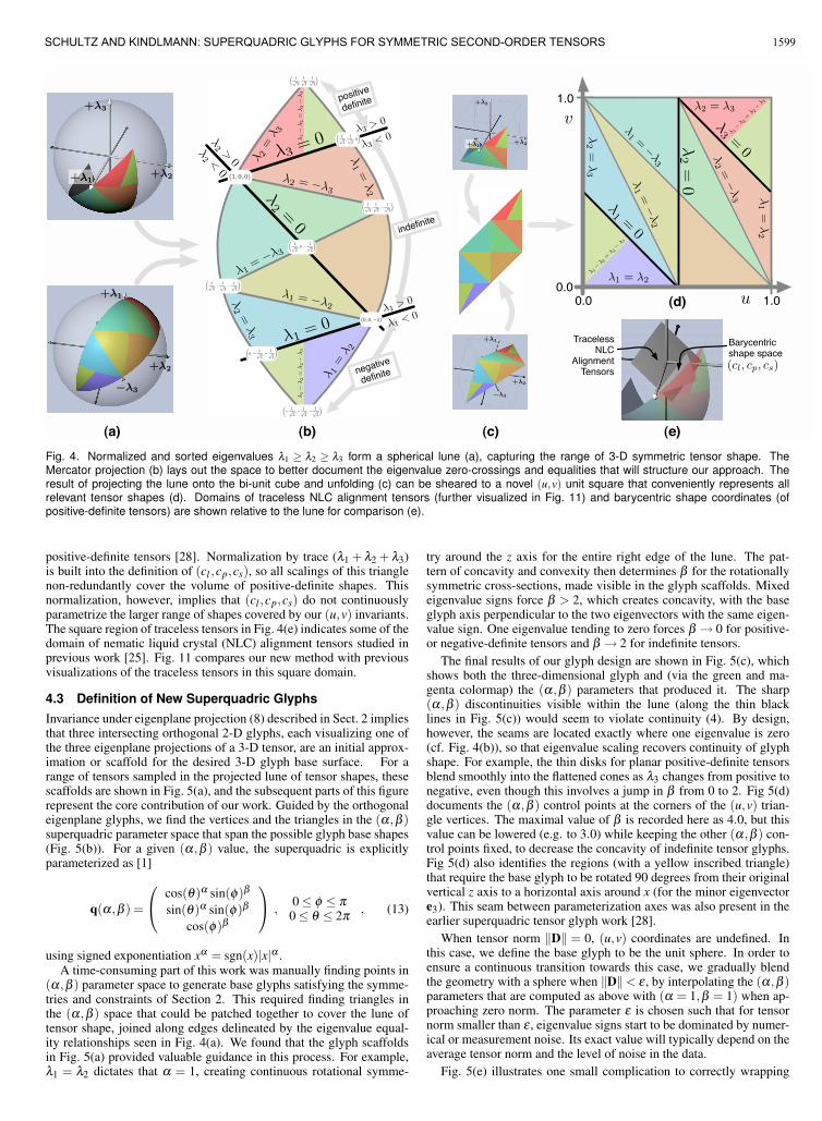
Though not the central contribution of this work, we suggest that theMercator projection is a novel and natural way to visualize the rangeof three-dimensional symmetric tensor shapes. A comparable view ofthe range of 3-D symmetric tensor shapes was illustrated for imageanalysis by Danielsson and Lin [5], but the space was parameterizedwith transforms of spherical harmonics, rather than the direct geomet-ric mapping we use. Mercator maps of tensor shape similar to thosedescribed in this Section provided the visual context for the originaldesign and evaluation of our new glyphs. The planar layout of the Mer-cator projection preserves the basic shape of the spherical lune, makingit easier to demarcate and reason about the triangular zones (coloredhere arbitrarily) bounded by the various eigenvalue zero-crossings andequalities. These zones delineate the regions over which our glyphbase geometry is defined and interpolated.
To obtain an explicit parameterization of tensor shape better suitedto glyph creation, we transform the lune to a unit square, shown inFig. 4(c) and (d). Normalized eigenvalues are projected to a bi-unitcube that is unfolded and sheared to create a unit (u,v) square:
λ ′i =λi
max(|λ1|, |λ2|, |λ3|); i = 1,2,3 (11)
u =1+λ ′2
2; v =
{1+λ ′3
2 −u+1 λ ′1 >−λ ′3λ ′1−1
2 −u+1 λ ′1 ≤−λ ′3(12)
There are no degeneracies in mapping forwards or backwards betweenthe lune and the (u,v) square, so either parameterization is an equallyvalid representation. The square makes it more computationally con-venient to represent positions inside the space, and to blend betweenshapes. As functions of the eigenvalues, the (u,v) shape coordinatesare tensor invariants (like tr(D) and ‖D‖), though we leave a detailedcomparison between (u,v) and established invariants to future work.
For comparison we show in Fig. 4(e) the relationship between thespherical lune and domains associated with two previous variable-geometry glyphs. The barycentric triangle parameterized by the(cl ,cp,cs) invariants [59] underlies previous superquadric glyphs for
1598 IEEE TRANSACTIONS ON VISUALIZATION AND COMPUTER GRAPHICS, VOL. 16, NO. 6, NOVEMBER/DECEMBER 2010
+λ2
+λ3
+λ1
+λ1
+λ2
−λ3
λ2
=0
λ1= 0
λ2 = −λ
3
λ1 = −λ
2
λ1=−λ3
λ1=
λ2
λ2=
λ3
λ1
=λ2
λ2
=λ3
λ2
>0
λ2
<0
λ1−
λ2
=λ
2−
λ3
λ1−
λ2
=λ
2−
λ3
λ2
=λ
3
λ2 = λ3
λ1
=λ
2
λ1 = λ2
λ1=
0
λ3=
0
λ2
=0
λ2=−
λ3
λ1=−λ3
λ1=−
λ2
u
v
λ 1−
λ 2
=λ 2−
λ 3
λ 1−
λ 2
=λ 2−
λ 3
(1, 0, 0)
(1√
2, 0,−
1√
2
)
(1√
3,
1√
3,−
1√
3
)
(1√
2,
1√
2, 0
)
(1√
3,
1√
3,
1√
3
)
(1√
3,−
1√
3,−
1√
3
)
(0, 0,−1)
(0,−
1√
2,−
1√
2
)
λ3= 0 λ3
< 0
λ1> 0
λ1< 0
(−
1√
3,−
1√
3,−
1√
3
)
λ3> 0
+λ2
+λ3
+λ1
+λ1
−λ3
+λ2
(cl, cp, cs)
Fig. 4. Normalized and sorted eigenvalues λ1 ≥ λ2 ≥ λ3 form a spherical lune (a), capturing the range of 3-D symmetric tensor shape. TheMercator projection (b) lays out the space to better document the eigenvalue zero-crossings and equalities that will structure our approach. Theresult of projecting the lune onto the bi-unit cube and unfolding (c) can be sheared to a novel (u,v) unit square that conveniently represents allrelevant tensor shapes (d). Domains of traceless NLC alignment tensors (further visualized in Fig. 11) and barycentric shape coordinates (ofpositive-definite tensors) are shown relative to the lune for comparison (e).
positive-definite tensors [28]. Normalization by trace (λ1 + λ2 + λ3)is built into the definition of (cl ,cp,cs), so all scalings of this trianglenon-redundantly cover the volume of positive-definite shapes. Thisnormalization, however, implies that (cl ,cp,cs) do not continuouslyparametrize the larger range of shapes covered by our (u,v) invariants.The square region of traceless tensors in Fig. 4(e) indicates some of thedomain of nematic liquid crystal (NLC) alignment tensors studied inprevious work [25]. Fig. 11 compares our new method with previousvisualizations of the traceless tensors in this square domain.
4.3 Definition of New Superquadric Glyphs
Invariance under eigenplane projection (8) described in Sect. 2 impliesthat three intersecting orthogonal 2-D glyphs, each visualizing one ofthe three eigenplane projections of a 3-D tensor, are an initial approx-imation or scaffold for the desired 3-D glyph base surface. For arange of tensors sampled in the projected lune of tensor shapes, thesescaffolds are shown in Fig. 5(a), and the subsequent parts of this figurerepresent the core contribution of our work. Guided by the orthogonaleigenplane glyphs, we find the vertices and the triangles in the (α ,β )superquadric parameter space that span the possible glyph base shapes(Fig. 5(b)). For a given (α ,β ) value, the superquadric is explicitlyparameterized as [1]
q(α ,β ) =
⎛⎝ cos(θ)α sin(φ)β
sin(θ)α sin(φ)β
cos(φ)β
⎞⎠ ,
0≤ φ ≤ π0≤ θ ≤ 2π
, (13)
using signed exponentiation xα = sgn(x)|x|α .
A time-consuming part of this work was manually finding points in(α ,β ) parameter space to generate base glyphs satisfying the symme-tries and constraints of Section 2. This required finding triangles inthe (α ,β ) space that could be patched together to cover the lune oftensor shape, joined along edges delineated by the eigenvalue equal-ity relationships seen in Fig. 4(a). We found that the glyph scaffoldsin Fig. 5(a) provided valuable guidance in this process. For example,λ1 = λ2 dictates that α = 1, creating continuous rotational symme-
try around the z axis for the entire right edge of the lune. The pat-tern of concavity and convexity then determines β for the rotationallysymmetric cross-sections, made visible in the glyph scaffolds. Mixedeigenvalue signs force β > 2, which creates concavity, with the baseglyph axis perpendicular to the two eigenvectors with the same eigen-value sign. One eigenvalue tending to zero forces β → 0 for positive-or negative-definite tensors and β → 2 for indefinite tensors.
The final results of our glyph design are shown in Fig. 5(c), whichshows both the three-dimensional glyph and (via the green and ma-genta colormap) the (α ,β ) parameters that produced it. The sharp(α ,β ) discontinuities visible within the lune (along the thin blacklines in Fig. 5(c)) would seem to violate continuity (4). By design,however, the seams are located exactly where one eigenvalue is zero(cf. Fig. 4(b)), so that eigenvalue scaling recovers continuity of glyphshape. For example, the thin disks for planar positive-definite tensorsblend smoothly into the flattened cones as λ3 changes from positive tonegative, even though this involves a jump in β from 0 to 2. Fig 5(d)documents the (α ,β ) control points at the corners of the (u,v) trian-gle vertices. The maximal value of β is recorded here as 4.0, but thisvalue can be lowered (e.g. to 3.0) while keeping the other (α ,β ) con-trol points fixed, to decrease the concavity of indefinite tensor glyphs.Fig 5(d) also identifies the regions (with a yellow inscribed triangle)that require the base glyph to be rotated 90 degrees from their originalvertical z axis to a horizontal axis around x (for the minor eigenvectore3). This seam between parameterization axes was also present in theearlier superquadric tensor glyph work [28].
When tensor norm ‖D‖ = 0, (u,v) coordinates are undefined. Inthis case, we define the base glyph to be the unit sphere. In order toensure a continuous transition towards this case, we gradually blendthe geometry with a sphere when ‖D‖< ε , by interpolating the (α ,β )parameters that are computed as above with (α = 1,β = 1) when ap-proaching zero norm. The parameter ε is chosen such that for tensornorm smaller than ε , eigenvalue signs start to be dominated by numer-ical or measurement noise. Its exact value will typically depend on theaverage tensor norm and the level of noise in the data.
Fig. 5(e) illustrates one small complication to correctly wrapping
1599SCHULTZ AND KINDLMANN: SUPERQUADRIC GLYPHS FOR SYMMETRIC SECOND-ORDER TENSORS

λ3
λ2λ1
(α, β)
α
β
v
u
Fig. 5. Creation of the new superquadric tensor glyphs. 3-D tensors sampled on the projected lune (a) are indicated by scaffolds of 2-D glyphsshowing the three orthogonal eigenplane projections, each visualized by the method sketched in Fig. 3. To find three-dimensional base glyphshapes conforming to these scaffolds, the range of superquadric shapes is sampled in (b), using green and magenta to indicate the varying α andβ parameters respectively. Careful inspection and experimentation led to choosing the triangles indicated in (b), which are mapped to the triangularzones (a), to produce the new 3-D glyphs in (c). The patchwork of triangles in (α,β ) parameter space, with vertices labeled for reference, is shownin (d). Yellow outlines show triangles where the base superquadric must be rotated to lie along the major eigenvector e1 rather than the minoreigenvector e3. A small adjustment to increase shape continuity at the center of the lune is shown in (e), as described in the text.
the glyph scaffolds (Fig. 5(a)) with superquadrics. Near the center ofthe palette (where λ1 ≈−λ3 and λ2 ≈ 0), the cross-section across themedium eigenvector e2 needs to be the star shape (seen at the centerof Fig. 3) created by β = 4. The cross-sections across the other eigen-vectors e1 and e3 involve an eigenvalue λ2 near zero, and hence shouldbe either the narrow diamonds or skinny rectangles also seen in Fig. 3.This particular combination of cross-sections, however, does not ex-ist in any available superquadric (Fig. 5(b)). Using (α ,β ) = (0,4)creates a visibly discontinuous change in seam orientation (Fig. 5(e)upper left), and also fails to have the desired diamond cross-sectionin the base glyph (Fig. 5(e) lower left). Therefore for this particulartensor shape, at the (0.5,0.5) center of (u,v) shape space, we define anew hybrid superquadric that is parameterized by (α ,β ,β ′):
yβ = sin(θ)α sin(φ)β (14)
z = cos(φ)β (15)
sβ ′ = sin(arccos(z1/β ′))β ′ (16)
smax = sin(φ)β (17)
h(α ,β ,β ′) =
⎛⎝ cos(θ)α sin(φ)β
yβ sβ ′smax
z
⎞⎠ ,
0≤ φ ≤ π0≤ θ ≤ 2π
. (18)
The effect of (16) is to recover from z the φ = arccos(z1/β ′) due to
setting β = β ′ in (13), then, to use this φ for a sin(φ)β ′ factor sβ ′
that scales the y coordinate of h. This forces the (y,z) cross-sectionof h(α ,β ,β ′) to match that of q(α ,β ′), while the (x,z) cross-sectionmatches that of q(α ,β ). Fig 5(d) identifies h(0,4,2) as the base glyphat (u,v) = (0.5,0.5) (Fig. 5(e) lower right), producing the more con-tinuous transition in Fig. 5(e) upper right.
‖D‖
=0
‖D‖
=1
λ
(a) (b)
Fig. 6. Halos support glyph perception when one or more eigenvaluesare near zero. Subfigure (a) shows the zero tensor (top) and the unittensor (bottom) at different zoom levels, using offset eigenvalues (left)and halos (right). Subfigure (b) shows a transition from indefinite topositive-definite tensors, with a rank-1 tensor at the center.
4.4 Glyph Halos
A complication with glyphs that follow (9) arises when two or all threeeigenvalues are near zero: In this case, the glyph degenerates to a lineor a point, so it is no longer visible. In practice, even the case of asingle near-zero eigenvalue can be problematic.
A simple solution to avoid this problem is to offset eigenvaluesaway from zero. However, it requires visual comparison to a refer-ence size to decide how close a displayed glyph is to the zero tensor.This is illustrated in Fig. 6(a), which compares the zero tensor (top) tothe unit tensor (bottom), but shows them at different zoom levels. Withoffset eigenvalues (left), both may result in the same visualization.
Therefore, we propose to render a halo around the tensor glyph. Ha-los have been used previously in visualization to enhance depth per-ception [53]; in our case, their goal is to ensure that even skinny struc-tures remain visible. The extent of the halo corresponds to a glyph withoffset eigenvalues (resulting in a fixed width in world space), but thevisual difference between the glyph itself and its halo clearly indicateswhether or not an eigenvalue is near zero (Fig. 6(a), right).
The halo can be colored to encode additional tensor information.
1600 IEEE TRANSACTIONS ON VISUALIZATION AND COMPUTER GRAPHICS, VOL. 16, NO. 6, NOVEMBER/DECEMBER 2010

In our examples, a colormap of tensor trace determines halo color.The utility of this is demonstrated in Fig. 6(b), showing tensors vary-ing gradually from indefinite (left) to positive-definite (right). For therank-1 tensor at the center, the glyph itself vanishes visually, but itshalo extent indicates both the magnitude of the non-zero eigenvalueand the direction of the associated eigenvector, while the halo colorindicates the eigenvalue sign. For a rank-1 tensor, the sign of the tracecoincides with the sign of the only non-zero eigenvalue.
Unlike the glyph shape itself, the shape of our halo is discontin-uous with eigenvalue sign changes. In practice, this did not becomeapparent in our experiments, and it can be considered to reflect thefact that halo shape visualizes eigenvalue signs, which are not contin-uous mathematical quantities. Image space methods for halo genera-tion [37] could be explored if, for some application, continuous halosare important. A near-zero trace is indicated by a gray halo, whichallows for a convenient check of whether or not a tensor is traceless.
4.5 Glyph Generation and Rendering
The process of glyph generation for a given tensor D is summarizedas follows: First, we find eigenvalues λi via the spectral decomposi-tion (1), sort and divide them by tensor norm ‖D‖ to obtain normal-
ized eigenvalues λi, and map the resulting descriptor of tensor shapeto (u,v) coordinates via (11). Next, we find out into which of the trian-gles shown in Fig. 5 (d) the values of (u,v) fall. Finally, a superquadricbase geometry is created as described in Section 4.3, with parametersα and β given by barycentric interpolation within the respective tri-angle. For reference, Fig. 5 (d) provides the (α ,β ) at each trianglevertex, as well as the special (α ,β ,β ′) value at the center of the (u,v)square. When ‖D‖ = 0, we set (α ,β ) = (1,1), with a continuousblending towards this case as described in Section 4.3.
Our OpenGL-based implementation stores vertex positions p of theglyph base geometry in the tensor’s eigenframe; non-uniform scaling,rotation and global scaling (as with s(‖D‖)R Λ in (9)) are achieved viaa suitable modelview matrix. The untransformed position p is passedfrom an OpenGL vertex shader to a fragment shader in a “varying”variable [45], where it is used to determine color. D is diagonal in itseigenframe, so it suffices to transfer the three eigenvalues to the GPU(once per glyph, in a “uniform” variable) for computing the quadraticform (10) in the fragment shader. Based on the resulting sign, orange(positive) or blue (negative) is selected as the fragment color, modu-lated by Phong shading.
Glyph halos are rendered in a two-pass approach: The extent ofthe glyphs rendered in the first pass is recorded in the stencil buffer.For the second pass, glyphs are made slightly larger by offsetting theeigenvalues by a constant amount, away from zero. To achieve thedesired halo effect, lighting is turned off in this second pass, and weonly render to pixels for which the stencil bit is not set.
4.6 Optimized Implementation
To accelerate glyph generation, we pre-compute a palette of represen-
tative base glyph shapes B(λi) by a uniform sampling of the (α ,β ) do-main shown in Fig. 5 (b). To render a new tensor, we can then computeits (α ,β ) and simply pick the nearest base shape from the palette. Notethat the final glyphs seen in the tensor visualization are not merely uni-form scalings and reorientations of the shapes sampled in the palette.Rather, the palette provides the axis-aligned base glyphs B. These aretransformed by (9) to glyphs G that accurately indicate tensor orienta-tion, shape, and scale. Since shapes in superquadric (α ,β ) space varysmoothly, the differences in shape of adjacent samples will no longerbe apparent visually when the discretization is fine enough. In our ex-perience, a palette resolution around 15×45 is sufficient to make theresult visually indistinguishable from the use of base geometry that iscomputed from scratch for each individual tensor.
To increase rendering performance, the shape palette can be keptin video memory, e.g., via OpenGL vertex buffer objects. Even witha tessellation that produces high-quality renderings (we use a singletriangle strip with 801 vertices per glyph), vertex positions and nor-mals (6× 4 = 24 bytes per vertex) for a 15× 45 palette consume801×24×15×45 bytes (≈ 12.7 MB) of video memory, which is very
(a) Reynolds glyphs (b) Superquadric glyphs
Fig. 7. The existing general glyphs for symmetric tensors, Reynoldsglyphs (a), suffer significantly from ambiguity problems due to self-occlusion by the wide lobes. Both the magnitude and sign of the re-maining eigenvalues can be hard to discern (top row), while from thesame viewpoint, the new superquadrics (b) show these clearly.
moderate with respect to modern hardware resources and leaves spacefor other visualization techniques that may complement the glyphs.The same index array can be used for all shapes.
With this implementation, only a pointer into the palette, a mod-elview matrix, and the set of eigenvalues (for coloring) is transferredto the graphics card per tensor. Despite the two-pass rendering forthe halos, we achieve interactive results (25 fps) when rendering morethan 3000 glyphs simultaneously in full mesh resolution on a largeviewport (1800×1000 pixels).
5 RESULTS
The polar plot seen in Fig. 2(b), sometimes referred to as a Reynoldsglyph, naturally generalizes to three dimensions and is an interestingpossibility for three-dimensional symmetric tensor visualization. AsFig. 7 shows, Reynolds glyphs suffer from ambiguity problems. Atcertain view angles (top row), the wide lobe associated with a singlepositive eigenvalue can hide basic information about the remainingeigenvalue magnitudes and signs. The superquadric glyphs clearly re-veal linearly shaped tensors with (left to right) zero, one, or two nega-tive eigenvalues. The same distinctions can only be inferred from theReynolds glyph when changing the viewpoint (bottom row).
In demonstrating the new glyphs on real-world data from differentcontexts, our hope is to highlight possible benefits of being able tofully “see” individual symmetric tensors. A simulation of the stresstensor field resulting from a two downward compressive point loads isan especially common dataset for hyperstreamline demonstrations [7],but it is less often visualized with glyphs, in part because, as othershave noted [26], existing glyphs are unsatisfactory. Fig. 8 visualizesthis canonical dataset with hyperstreamlines and our new glyphs. Ten-
sor norms are significantly compressed, by setting s(‖D‖) ∝ ‖D‖1/10
in (6), due to the very wide variation of eigenvalues. The longest axisof glyphs in Fig. 8(a) indicates the minor eigenvector (direction ofmaximal compression) typically traced with hyperstreamlines. Theglyphs additionally reveal the variation of stress patterns near the cen-ter of the dataset, and halos clarify the orientation of the narrowestglyphs elsewhere. The horizontal slice in Fig. 8(b) shows the radialstructure of the two compressive loads, as well as locations and di-rections along which there is expansion (positive eigenvalues in or-ange). A previous glyph for stress tensor visualization in geomechan-ics depicts the orientation of the plane spanned by the two eigenvectorswith the largest eigenvalue magnitudes [40]. By symmetry preserva-tion (3), our glyphs also depict this orientation whenever the tensorshape strongly determines it, while also showing the principle eigen-vector directions traced by hyperstreamlines.
Another tensor field more often depicted by streamlines or othermethods than by individual glyphs are geometry tensors G on smooththree-dimensional implicit surfaces:
G = (I−nnT )H(I−nnT )/‖g‖ (19)
where n = g/‖g‖ is the normalized gradient and H is the Hessian of ascalar function f (x). The eigenvalues of G are zero and the principalcurvatures (of the isosurfaces of f ) κ1 and κ2. Invariants of G can be
1601SCHULTZ AND KINDLMANN: SUPERQUADRIC GLYPHS FOR SYMMETRIC SECOND-ORDER TENSORS

(a) Glyphs on vertical cutting plane
(b) Glyphs through horizontal cutting plane
Fig. 8. Glyphs in the double point load stress tensor field reveal theminor eigenvector along which hyperstreamlines [7] are traced (a), andthe variation in stress with distance from the load (b).
volume rendered [32], but its eigenvectors are commonly used in non-photo-realistic rendering, e.g. curvature-based strokes [11, 14, 19].Inspecting geometry tensors could help debug an NPR method givingunexpected results in an unfamiliar dataset. Fig. 9(a) visualizes geom-etry tensors G on an isosurface (sampled by a particle system [39]) ofan ear from the Visible Human male CT scan. Variations in surfacecurvature are reflected in the new glyphs: convex (blue circles), con-cave (orange circles), and saddles (orange and blue stars). For compar-ison, Fig. 9(b) shows the full Hessian H from which G was computed.
The new glyphs may also have a role in visualizing the tensor in-gredients of image analysis methods such as edge detection. One edgedefinition is zero-crossing on the second directional derivative alongthe gradient direction, f ′′ = nT Hn. This edge surface is sampled bya particle system [33] in Fig. 9(c), showing the Hessians at the edgelocations, and revealing close similarities with the geometry tensorson the isosurface in Fig. 9(a), indicating that one of the Hessian eigen-values is near zero even though this is not part of the edge defini-tion. Another edge definition is the zero-crossing of the Laplacian∇2 f = tr(H), and Fig. 9(d) illustrates the difference between the Hes-sians on this surface and those in Fig. 9(c). The consistently gray glyphhalos in Fig. 9(d) indicate that these are traceless tensors.
As a demonstration of the glyphs in a 2-D visualization, Fig. 10visualizes a cross-section of a simulation of jet flow rightward into asteady medium, causing turbulence. Glyphs of rate-of-deformationstensors document how an infinitesimal volume is stretched or com-pressed as it moves along the flow. A backdrop of line integral con-volution [4] (with contrast modulated by velocity) provides visualcontext. Fig. 10(a) uses the exponentially-scaled ellipses of [34] tomap tensors with negative eigenvalues to positive-definite tensors suit-able for ellipsoid visualization. When the absolute difference betweeneigenvalues becomes too large, these glyphs can become so stretchedthat they overlap each other and extend over a significant portion ofthe domain, undermining the locality normally enjoyed by glyphs.Such stretching also reduces the visual presence of the needle-likeglyphs for tensors with larger norms, contrary to scale preservation (6).Fig. 10(b) uses our superquadric glyphs with s(‖D‖) ∝ ‖D‖. The as-pect ratio reflects the relative eigenvalue magnitudes, the size correctlyindicates the tensor norm, and pointed glyph shapes clearly commu-nicate eigenvector directions. With compression of scale variation
(a) Geometry Tensors G on Isosurface (b) Hessians H on Isosurface
(c) Hessians H on f ′′ zero-crossing (d) Hessians H on ∇2 f zero-crossing
Fig. 9. Visualization of geometry tensors (a) and Hessians associ-ated with isosurfaces (b) and two different definitions of edges, zero-crossings of the second-directional derivative (c) and the Laplacian (d).These results use s(‖D‖) ∝ ‖D‖1/2 in (6).
(s(‖D‖) ∝ ‖D‖1/2), Fig. 10(c) better shows the directional patternswhere the tensor norm is low. Colormapping the rate-of-deformationtensor trace with glyph halos highlights the regions of over-all stretch-ing or compression, especially along the bottom edge of the domain.
Finally, Fig. 11 demonstrates how our new glyph performs trace-less tensor visualization, in a side-by-side comparison to the dedi-cated traceless NLC tensor glyphs by Jankun-Kelly et al. [25]. Trace-less tensors form a plane in eigenvalue space, and we are visualiz-ing samples from a square within this plane, centered around the zerotensor (cf. Fig. 4(e)). Unlike the traceless glyph, which maps ten-sor norm to glyph sharpness, our glyph expresses norm by its overallscale s(‖D‖) ∝ ‖D‖. Consequently, the traceless glyph requires pre-specification of maximum eigenvalue magnitudes (which are mappedto perfect sharpness), while our glyph can be used without such priorinformation. Another notable difference is that limiting their glyph totraceless tensors allows Jankun-Kelly et al. to make use of parts of thesuperquadric shape space – including cylinders and boxes – that ourapproach sets aside for positive- or negative-definite tensors.
6 CONCLUSION
Visualization research has made significant progress in visualizingsecond-order tensor fields, but has mostly concentrated on the positive-definite case. Faced with indefinite tensors, a frequent strategy is tomap them to positive-definite tensors prior to visualization [34, 22,21, 52, 33]. Even when bijective mappings are used (so mathemati-cally, no information is lost), such mappings still visually obscure thedifference between positive and negative eigenvalues, which is a fun-damental qualitative aspect in various applications.
Therefore, we propose an extension of a previous positive-definitetensor glyph [28] to the full space of symmetric second-order tensors.Our glyph emphasizes differences in eigenvalue sign in a way that,unlike the Reynolds glyph [18], prevents small eigenvalues from be-ing occluded by larger ones. We also propose to use halos to ensuretensor glyph visibility even when one or more eigenvalues are nearzero. Finally, we present a time- and memory-efficient implementa-
1602 IEEE TRANSACTIONS ON VISUALIZATION AND COMPUTER GRAPHICS, VOL. 16, NO. 6, NOVEMBER/DECEMBER 2010

(a) Exponentially-scaled ellipses
(b) Superquadric tensor glyphs; s(‖D‖) ∝ ‖D‖
(c) Superquadric tensor glyphs; s(‖D‖) ∝ ‖D‖1/2
Fig. 10. Rate-of-deformation tensors visualized in a computational fluiddynamics simulation with exponentially-scaled ellipsoids (a) and our su-perquadric glyphs (b), (c).
tion, based on a small pre-computed palette of glyph shapes which arerepresented by a single triangle strip each. They are kept in GPU mem-ory and instantiated as needed, combined with a simple and effectiveshader-based coloring to indicate the quadratic form.
Tensor glyph design is ultimately a creative process that balancesaesthetic, computational, and mathematical considerations, and op-tionally some level of specialization to a particular visualization appli-cation. An interesting counterpart to our approach is the work of Keefeet al. [27] that fostered the design of multi-variate fluid flow visualiza-tions through artistic collaborations, which started with visual mediaand then moved to computer graphics algorithms and the constraintsthey impose. Our initial work in glyph design began with hand-drawnexperimental versions of Figs. 3, 4, and 5, but the mathematical guide-lines of Section 2 were adopted from the outset as constructive con-straints in the design process. Our glyph is designed to preserve sym-metry, continuity, and invariance under scaling and eigenplane pro-jection, while minimizing visual ambiguity. By adhering to these con-straints, our glyph unambiguously reflects the mathematical propertiesof the underlying tensors, and produces useful visualizations in a rangeof applications.
Following on recent work by Jankun-Kelly et al. [24] for perceptu-ally evaluating traceless tensor glyphs, future work may quantitativelyinvestigate the effectiveness of our glyph for general symmetric ten-sors, perhaps in the context of particular application areas. Special-purpose glyphs may offer advantages for particular applications in-
(0,1/ √
2,−
1 √2 )
(√2/3, −1/
√6, −1/
√6)
(a) Traceless superquadric tensor
glyphs proposed in [25]
(0,1/ √
2,−
1 √2 )
(√2/3, −1/
√6, −1/
√6)
(b) Our symmetric tensor glyphs,
applied to the same traceless plane
Fig. 11. When applied to traceless tensors, our glyph (b) uses a smallerpart of superquadric shape space than a previous approach that spe-cialized on the traceless case (a), but supplements it with color.
volving tensor fields, such as mapping glyph shape to important phys-ically meaningful properties of the field. In contrast, our approachhas aimed for generality across applications, and is most likely nota unique solution to the chosen mathematical constraints. We inviteother researchers to explore new ways of satisfying some or all of thedesign constraints according to their own needs, perhaps starting withFig. 1 as a framework for sketching new glyph shapes.
ACKNOWLEDGMENTS
We thank the reviewers for their constructive comments. The pre-sentation of the glyph design principles benefited from discussionsat the 2009 Dagstuhl Scientific Visualization Seminar 09251. Flowdata courtesy of Wolfgang Kollmann, MAE Department of the Uni-versity of California Davis. This work was supported by a fellow-ship within the Postdoc Program of the German Academic ExchangeService (DAAD). Our open-source implementation is described athttp://people.cs.uchicago.edu/˜glk/sqd/
REFERENCES
[1] A. Barr. Superquadrics and angle-preserving transformations. IEEE
Computer Graphics and Applications, 18(1):11–23, 1981.
[2] P. Basser, J. Mattiello, and D. LeBihan. MR diffusion tensor spectroscopy
and imaging. Biophysics Journal, 66(1):259–267, 1994.
[3] W. Benger and H.-C. Hege. Tensor splats. In Visualization and Data
Analysis (Proc. SPIE), volume 5295, pages 151–162, 2004.
[4] B. Cabral and L. C. Leedom. Imaging vector fields using line integral
convolution. In Computer Graphics (Proc. ACM SIGGRAPH), pages
263–270, 1993.
[5] P. Danielsson, Q. Lin, and Q. Ye. Efficient detection of Second-Degree
variations in 2D and 3D images. Journal of Visual Communication and
Image Representation, 12(3):255–305, 2001.
[6] W. C. de Leeuw and J. J. van Wijk. A probe for local flow field visualiza-
tion. In Proc. IEEE Visualization, pages 39–45, 1993.
[7] T. Delmarcelle and L. Hesselink. Visualizing second-order tensor fields
with hyperstreamlines. IEEE Computer Graphics and Applications,
13(4):25–33, 1993.
[8] C. Dick, J. Georgii, R. Burgkart, and R. Westermann. Stress tensor field
visualization for implant planning in orthopedics. IEEE Trans. on Visu-
alization and Computer Graphics, 15(6):1399–1406, 2009.
[9] Z. Ding, J. C. Gore, and A. W. Anderson. Classification and quantifi-
cation of neuronal fiber pathways using diffusion tensor MRI. Magnetic
Resonance in Medicine, 49(4):716–721, 2003.
[10] R. K. Dodd. A new approach to the visualization of tensor fields. Graph-
ical Models and Image Processing, 60(4):286–303, 1998.
[11] G. Elber. Line art illustrations of parametric and implicit forms. IEEE
Trans. on Visualization and Computer Graphics, 4(1):71–81, 1998.
[12] C. Feddern, J. Weickert, and B. Burgeth. Level-set methods for tensor-
valued images. In O. D. Faugeras and N. Paragios, editors, Proc. Second
IEEE Workshop on Geometric and Level Set Methods in Computer Vision,
pages 65–72, 2003.
1603SCHULTZ AND KINDLMANN: SUPERQUADRIC GLYPHS FOR SYMMETRIC SECOND-ORDER TENSORS

[13] L. Feng, I. Hotz, B. Hamann, and K. Joy. Anisotropic noise samples.
IEEE Trans. on Visualization and Computer Graphics, 14(2):342–354,
2008.
[14] A. Girshick, V. Interrante, S. Haker, and T. Lemoine. Line direction mat-
ters: An argument for the use of principal directions in 3D line drawings.
In Proc. 1st Intl. Symp. Non-Photorealistic Animation and Rendering,
pages 43–52. ACM, 2000.
[15] A. Globus, C. Levit, and T. Lasinski. A tool for visualizing the topology
of three-dimensional vector fields. In Proc. IEEE Visualization, pages
33–40, 1991.
[16] R. Haber. Visualization techniques for engineering mechanics. Comput-
ing Systems in Engineering, 1(1):37–50, 1990.
[17] H. Hagen, S. Hahmann, T. Schreiber, Y. Nakajima, B. Wordenweber, and
P. Hollemann-Grundstedt. Surface interrogation algorithms. IEEE Com-
puter Graphics and Applications, 12(5):53–60, 1992.
[18] Y. M. A. Hashash, J. I.-C. Yao, and D. C. Wotring. Glyph and hyper-
streamline representation of stress and strain tensors and material consti-
tutive response. Intl. Journal for Numerical and Analytical Methods in
Geomechanics, 27:603–626, 2003.
[19] A. Hertzmann and D. Zorin. Illustrating smooth surfaces. In Computer
Graphics (Proc. ACM SIGGRAPH), pages 517–526, 2000.
[20] L. Hesselink, Y. Levy, and Y. Lavin. The topology of symmetric, second-
order 3D tensor fields. IEEE Trans. on Visualization and Computer
Graphics, 3(1):1–11, 1997.
[21] I. Hotz, L. Feng, H. Hagen, B. Hamann, and K. Joy. Tensor field vi-
sualization using a metric interpretation. In J. Weickert and H. Hagen,
editors, Visualization and Processing of Tensor Fields, chapter 16, pages
269–280. Springer, 2006.
[22] I. Hotz, L. Feng, H. Hagen, B. Hamann, K. Joy, and B. Jeremic. Physi-
cally based methods for tensor field visualization. In Proc. IEEE Visual-
ization, pages 123–130, 2004.
[23] E. Hsu. Generalized line integral convolution rendering of diffusion
tensor fields. In Proc. International Society of Magnetic Resonance in
Medicine (ISMRM), page 790, 2001.
[24] T. J. Jankun-Kelly, Y. S. Lanka, and J. E. Swan II. An evaluation of
glyph perception for real symmetric traceless tensor properties. Com-
puter Graphics Forum (Special Issue on EuroVis 2010), 29(3):1133–
1142, 2010.
[25] T. J. Jankun-Kelly and K. Mehta. Superellipsoid-based, real symmetric
traceless tensor glyphs motivated by nematic liquid crystal alignment vi-
sualization. IEEE Trans. on Visualization and Computer Graphics (Proc.
IEEE Visualization), 12(5):1197–1204, 2006.
[26] B. Jeremic, G. Scheuermann, J. Frey, Z. Yang, B. Hamann, K. I. Joy,
and H. Hagen. Tensor visualizations in computational geomechanics.
Intl. Journal for Numerical and Analytical Methods in Geomechanics,
26(10):925–944, 2002.
[27] D. Keefe, D. Karelitz, E. Vote, and D. H. Laidlaw. Artistic collaboration
in designing VR visualizations. IEEE Computer Graphics and Applica-
tions, 25(2):18–23, 2005.
[28] G. Kindlmann. Superquadric tensor glyphs. In Proc. EG/IEEE TCVG
Symposium on Visualization, pages 147–154, May 2004.
[29] G. Kindlmann, X. Tricoche, and C.-F. Westin. Delineating white matter
structure in diffusion tensor MRI with anisotropy creases. Medical Image
Analysis, 11(5):492–502, 2007.
[30] G. Kindlmann, D. Weinstein, and D. Hart. Strategies for direct volume
rendering of diffusion tensor fields. IEEE Trans. on Visualization and
Computer Graphics, 6(2):124–138, 2000.
[31] G. Kindlmann and C.-F. Westin. Diffusion tensor visualization with
glyph packing. IEEE Trans. on Visualization and Computer Graphics,
12(5):1329–1335, 2006.
[32] G. Kindlmann, R. Whitaker, T. Tasdizen, and T. Moller. Curvature-based
transfer functions for direct volume rendering: Methods and applications.
In Proc. IEEE Visualization 2003, pages 513–520, 2003.
[33] G. L. Kindlmann, R. S. J. Estepar, S. M. Smith, and C.-F. Westin. Sam-
pling and visualizing creases with scale-space particles. IEEE Trans. on
Visualization and Computer Graphics, 15(6):1415–1424, 2009.
[34] R. M. Kirby, H. Marmanis, and D. H. Laidlaw. Visualizing multivalued
data from 2D incompressible flows using concepts from painting. In Proc.
IEEE Visualization, pages 333–340, 1999.
[35] D. H. Laidlaw, E. T. Ahrens, D. Kremers, M. J. Avalos, R. E. Jacobs, and
C. Readhead. Visualizing diffusion tensor images of the mouse spinal
cord. In Proc. IEEE Visualization, pages 127–134, 1998.
[36] M. A. Livingston. Visualization of rotation fields. In Proc. IEEE Visual-
ization, pages 491–494, 1997.
[37] T. Luft, C. Colditz, and O. Deussen. Image enhancement by unsharp
masking the depth buffer. ACM Transactions on Graphics (Proc. ACM
SIGGRAPH), 25(3):1206–1213, 2006.
[38] J. E. Marsden and A. J. Tromba. Vector Calculus. W.H. Freeman and
Company, New York, New York, 1996.
[39] M. D. Meyer, P. Georgel, and R. T. Whitaker. Robust particle systems
for curvature dependent sampling of implicit surfaces. In Proc. Shape
Modeling and Applications (SMI), pages 124–133, June 2005.
[40] A. Neeman, B. Jeremic, and A. Pang. Visualizing tensor fields in geome-
chanics. In Proc. IEEE Visualization, pages 35–42, 2005.
[41] E. Ozarslan and T. Mareci. Generalized diffusion tensor imaging and
analytical relationships between diffusion tensor imaging and high an-
gular resolution diffusion imaging. Magnetic Resonance in Medicine,
50(5):955–965, 2003.
[42] S. Pajevic and C. Pierpaoli. Color schemes to represent the orientation
of anisotropic tissues from diffusion tensor data: Application to white
matter fiber tract mapping in the human brain. Magnetic Resonance in
Medicine, 42(3):526–540, 1999.
[43] F. H. Post, B. Vrolijk, H. Hauser, R. S. Laramee, and H. Doleisch. The
state of the art in flow visualisation: Feature extraction and tracking.
Computer Graphics Forum, 22(4):775–792, 2003.
[44] T. Ropinski, J. Meyer-Spradow, M. Specht, K. H. Hinrichs, and B. Preim.
Surface glyphs for visualizing multimodal volume data. In Proc. Vision,
Modeling, and Visualization, pages 3–12, 2007.
[45] R. J. Rost. OpenGL shading manual. Addison-Wesley, 2nd edition, 2006.
[46] W. Schroeder, K. Martin, and B. Lorensen. The Visualization Toolkit: An
Object Oriented Approach to Graphics, chapter 6. Kitware, 2003.
[47] W. J. Schroeder and K. M. Martin. The Visualization Handbook, chapter
1: Overview of Visualization, pages 3–38. Academic Press, 2004.
[48] T. Schultz and G. Kindlmann. A maximum enhancing higher-order tensor
glyph. Computer Graphics Forum (Proc. EuroVis), 29(3):1143–1152,
2010.
[49] T. Schultz, H. Theisel, and H.-P. Seidel. Crease surfaces: From theory
to extraction and application to diffusion tensor MRI. IEEE Trans. on
Visualization and Computer Graphics, 16(1):109–119, 2010.
[50] C. D. Shaw, D. S. Ebert, J. M. Kukla, A. Zwa, I. Soboroff, and D. A.
Roberts. Data visualization using automatic, perceptually-motivated
shapes. In Visual Data Exploration and Analysis (Proc. SPIE), volume
3298, pages 208–213, 1998.
[51] A. Sigfridsson, T. Ebbers, E. Heiberg, and L. Wigstrom. Tensor field
visualisation using adaptive filtering of noise fields combined with glyph
rendering. In Proc. IEEE Visualization, pages 371–378, 2002.
[52] V. Slavin, R. Pelcovits, G. Loriot, A. Callan-Jones, and D. Laidlaw. Tech-
niques for the visualization of topological defect behavior in nematic
liquid crystals. IEEE Trans. on Visualization and Computer Graphics,
12(5):1323–1328, 2006.
[53] M. Tarini, P. Cignoni, and C. Montani. Ambient occlusion and edge cue-
ing to enhance real time molecular visualization. IEEE Transactions on
Visualization and Computer Graphics, 12(5):1237–1244, 2006.
[54] H. Theisel, T. Weinkauf, H.-C. Hege, and H.-P. Seidel. Saddle connec-
tors - an approach to visualizing the topological skeleton of complex 3D
vector fields. In Proc. IEEE Visualization, pages 225–232, 2003.
[55] W.-S. Tong, C.-K. Tang, P. Mordohai, and G. Medioni. First order aug-
mentation to tensor voting for boundary inference and multiscale anal-
ysis in 3D. IEEE Trans. on Pattern Analysis and Machine Intelligence,
26(5):594–611, 2004.
[56] A. Vilanova, S. Zhang, G. Kindlmann, and D. H. Laidlaw. An introduc-
tion to visualization of diffusion tensor imaging and its applications. In
J. Weickert and H. Hagen, editors, Visualization and Processing of Tensor
Fields, pages 121–153. Springer, 2006.
[57] J. Weickert and H. Hagen, editors. Visualization and Processing of Tensor
Fields. Springer, 2006.
[58] E. W. Weisstein. CRC Concise Encyclopedia of Mathematics, page 1894.
CRC Press, 2003.
[59] C.-F. Westin, S. E. Maier, B. Khidhir, P. Everett, F. A. Jolesz, and R. Kiki-
nis. Image processing for diffusion tensor magnetic resonance imaging.
In Proceedings MICCAI, volume 1679 of LNCS, pages 441–452, 1999.
[60] M. R. Wiegell, H. B. W. Larsson, and V. J. Wedeen. Fiber crossing in
human brain depicted with diffusion tensor MR imaging. Radiology,
217(3):897–903, 2000.
[61] X. Zheng and A. Pang. HyperLIC. In Proc. IEEE Visualization, pages
249–256, 2003.
1604 IEEE TRANSACTIONS ON VISUALIZATION AND COMPUTER GRAPHICS, VOL. 16, NO. 6, NOVEMBER/DECEMBER 2010