superstructure / girder bridges · 2020-03-10 · steel-concrete composite bridges are usually more...
TRANSCRIPT

Superstructure / Girder bridges
10.03.2020 1
Design and erection
Steel and steel-concrete composite girders
ETH Zürich | Chair of Concrete Structures and Bridge Design | Bridges lecture
Steel and composite girders
10.03.2020 2ETH Zürich | Chair of Concrete Structures and Bridge Design | Bridges lecture
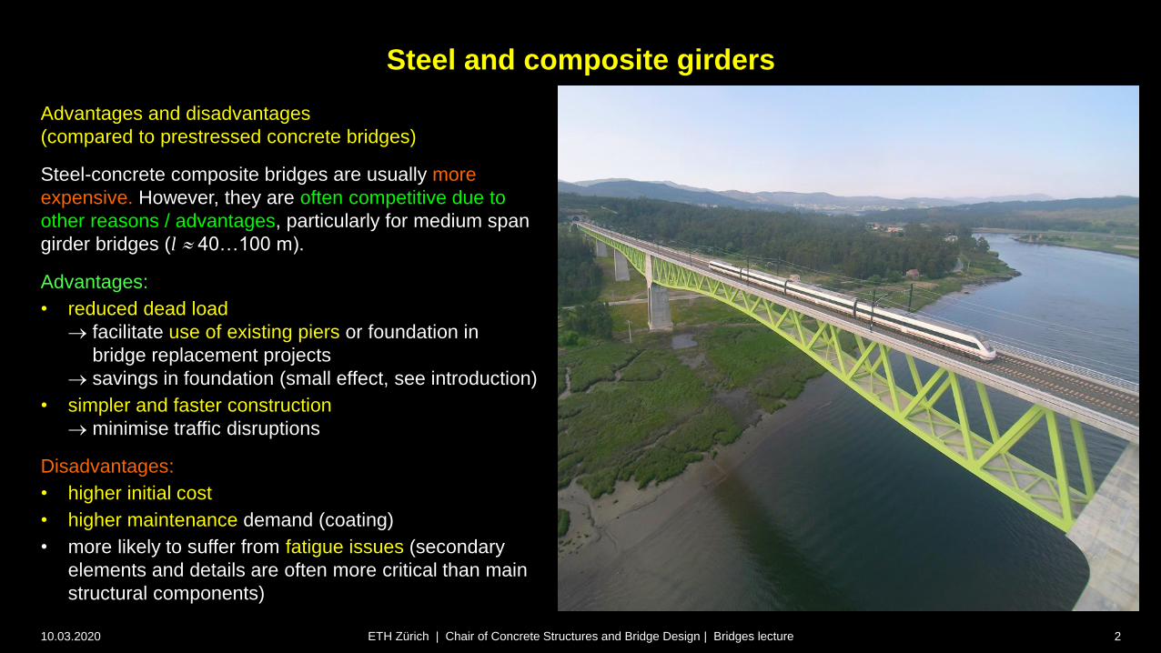
Advantages and disadvantages
(compared to prestressed concrete bridges)
Steel-concrete composite bridges are usually more
expensive. However, they are often competitive due to
other reasons / advantages, particularly for medium span
girder bridges (l 40…100 m).
Advantages:
• reduced dead load
facilitate use of existing piers or foundation in
bridge replacement projects
savings in foundation (small effect, see introduction)
• simpler and faster construction
minimise traffic disruptions
Disadvantages:
• higher initial cost
• higher maintenance demand (coating)
• more likely to suffer from fatigue issues (secondary
elements and details are often more critical than main
structural components)

Superstructure / Girder bridges
10.03.2020 3
Design and erection
Steel and steel-concrete composite girders
Typical cross-sections and details
ETH Zürich | Chair of Concrete Structures and Bridge Design | Bridges lecture

Steel and composite girders – Typical cross-sections and details
10.03.2020 4ETH Zürich | Chair of Concrete Structures and Bridge Design | Bridges lecture
Open cross-sections
• Twin girders (plate girders)
concrete deck l ≤ ca. 125 m
orthotopic deck l > ca. 125 m
• Twin box girder
• Multi-girder2b
b
3.0 m

Steel and composite girders – Typical cross-sections and details
10.03.2020 5ETH Zürich | Chair of Concrete Structures and Bridge Design | Bridges lecture
Closed cross-sections
• Steel U section closed by concrete deck slab
• Closed steel box section with concrete deck
• Closed steel box section with orthotropic deck
• Girder with “double composite action”
(concrete slabs on top and bottom)
• Multi-cell box section (for cable stayed or
suspension bridges)
The distinction between open and closed cross-
sections is particularly relevant for the way in
which the bridge resists torsion, see spine model.
Steel and composite girders – Typical cross-sections and details
10.03.2020 6ETH Zürich | Chair of Concrete Structures and Bridge Design | Bridges lecture
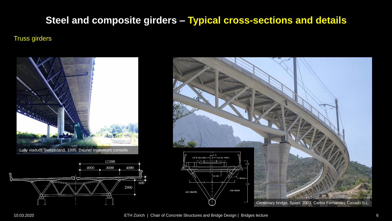
Truss girders
Lully viaduct, Switzerland, 1995. Dauner Ingénieurs conseils
Centenary bridge, Spain, 2003. Carlos Fernandez Casado S.L.

Steel and composite girders – Typical cross-sections and details
10.03.2020 7ETH Zürich | Chair of Concrete Structures and Bridge Design | Bridges lecture
Slenderness h / l for steel beams
l
h
1 1
25 20
h
l
1 1
50 40
h
l
Simple beam
h / l
Continuous beam
h / l
Plate girder 1/18 ... 1/12 1/28 ... 1/20
Box girder 1/25 ... 1/20 1/30 ... 1/25
Truss 1/12 ... 1/10 1/16 ... 1/12
Structural form
Type of beam
Usual slenderness h / l for steel girders in road bridges

Steel and composite girders – Typical cross-sections and details
10.03.2020 8ETH Zürich | Chair of Concrete Structures and Bridge Design | Bridges lecture
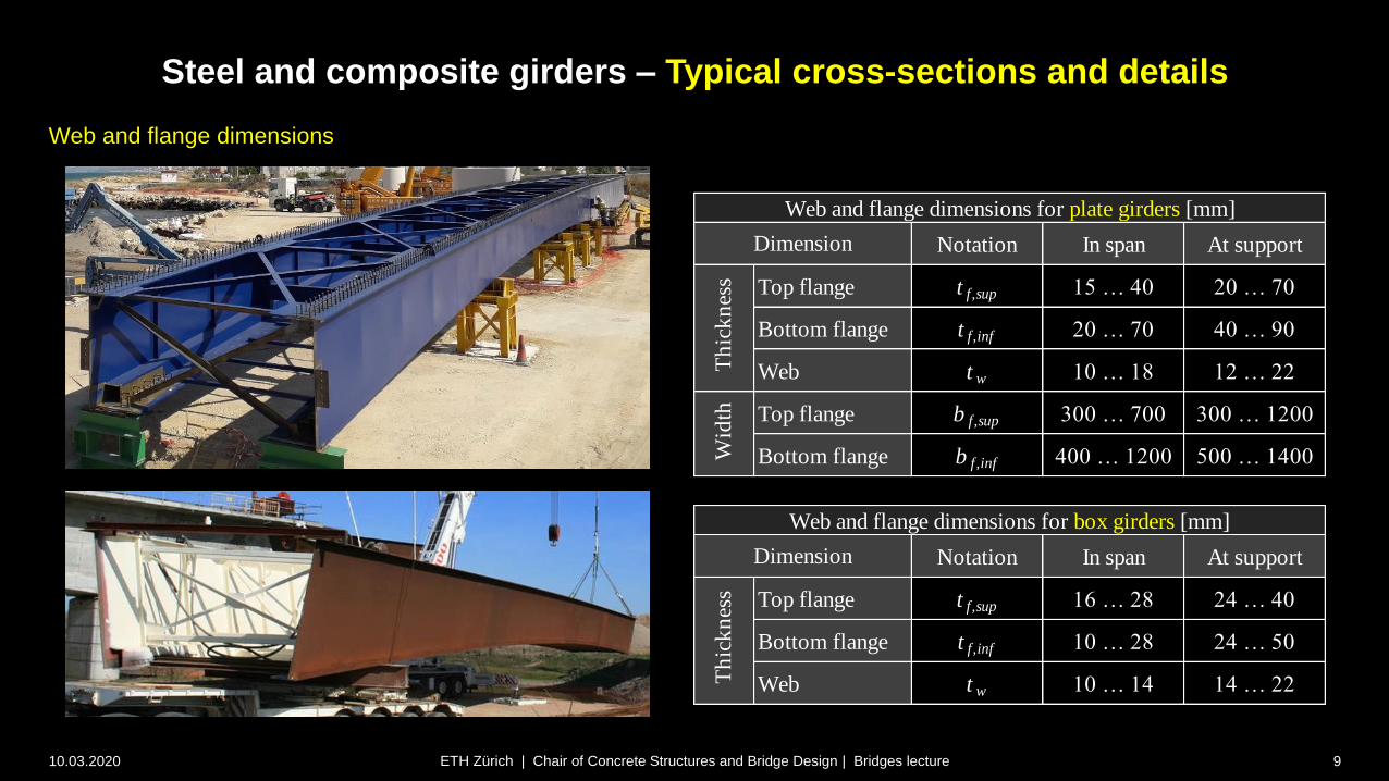
Web and flange dimensions
Notation In span At support
Top flange t f,sup 15 … 40 20 … 70
Bottom flange t f,inf 20 … 70 40 … 90
Web t w 10 … 18 12 … 22
Top flange b f,sup 300 … 700 300 … 1200
Bottom flange b f,inf 400 … 1200 500 … 1400
Notation In span At support
Top flange t f,sup 16 … 28 24 … 40
Bottom flange t f,inf 10 … 28 24 … 50
Web t w 10 … 14 14 … 22
Dimension
Th
ick
nes
sW
idth
Th
ick
nes
s
Web and flange dimensions for plate girders [mm]
Dimension
Web and flange dimensions for box girders [mm]
Notation In span At support
Top flange t f,sup 15 … 40 20 … 70
Bottom flange t f,inf 20 … 70 40 … 90
Web t w 10 … 18 12 … 22
Top flange b f,sup 300 … 700 300 … 1200
Bottom flange b f,inf 400 … 1200 500 … 1400
Notation In span At support
Top flange t f,sup 16 … 28 24 … 40
Bottom flange t f,inf 10 … 28 24 … 50
Web t w 10 … 14 14 … 22
Dimension
Th
ick
nes
sW
idth
Th
ick
nes
s
Web and flange dimensions for plate girders [mm]
Dimension
Web and flange dimensions for box girders [mm]
Steel and composite girders – Typical cross-sections and details
10.03.2020 9ETH Zürich | Chair of Concrete Structures and Bridge Design | Bridges lecture
Web and flange dimensions

Superstructure / Girder bridges
10.03.2020 10
Design and erection
Steel and steel-concrete composite girders
Structural analysis and design – General remarks
ETH Zürich | Chair of Concrete Structures and Bridge Design | Bridges lecture

Structural analysis and design – General Remarks
31.01.2020 11ETH Zürich | Chair of Concrete Structures and Bridge Design | Bridges lecture
Overview
• Major differences compared to building structures
• Spine and grillage models usual
• Usually significant eccentric loads torsion relevant
• Basically, the following analysis methods (see lectures Stahlbau)
are applicable also to steel and steel-concrete composite bridges:
PP: Plastic analysis, plastic design (rarely used in bridges)
EP: Elastic analysis, plastic design
EE: Elastic analysis, elastic design
EER: Elastic analysis, elastic design with reduced section
• Linear elastic analysis is usual, without explicit moment
redistribution Methods EP, EE, EER usual, using transformed
section properties (ideelle Querschnittswerte)
• Moving loads design using envelopes of action effects
• Steel girders with custom cross-sections (slender, welded plates)
are common for structural efficiency and economy
plate girders (hot-rolled profiles only for secondary elements)
stability essential in analysis and design
slender plates require use of Method EE or even EER

Structural analysis and design – General Remarks
31.01.2020 12ETH Zürich | Chair of Concrete Structures and Bridge Design | Bridges lecture
Overview
• Construction is usually staged (in cross-section)
see behind
• Fatigue is the governing limit state in many cases in bridges
limited benefit of high strength steel grades
avoid details with low fatigue strength
see lectures Stahlbau (only selected aspects treated here)
• Precamber is often required and highly important
(steel girders often require large precamber)
as in concrete structures: no «safe side» in precamber
account for long-term effects
(creep and shrinkage of concrete deck)
account for staged construction
• Shear transfer between concrete deck and steel girders
needs to be checked in composite bridges
see shear connection
• Effective width to be considered. Figure shows values for
concrete flanges, steel plates see EN 1993-1-5
Effective width of concrete deck in a composite girder
used for global analysis (EN1994-2)
2
0
1
2
0
1
8
0.55 0.025 1
eff ei
i
eei i
eff i ei
i
ei
ei
b b b
Lb b
b b b
L
b
Interior support / midspan:
End support:

Structural analysis and design – General Remarks
31.01.2020 13ETH Zürich | Chair of Concrete Structures and Bridge Design | Bridges lecture
Slender plates
• In order to save weight and material, slender steel plates
are often used in bridges (particularly for webs and wide
flanges of box girders)
Plate buckling cannot be excluded a priori (unlike hot-
rolled profiles common in building structures)
Analysis method depends on cross-section classes
(known from lectures Stahlbau, see figure)
• The steel strength cannot be fully used in sections of
Class 3 or 4 (resp. the part of the plates outside the
effective width is ineffective)
For structural efficiency, compact sections (Class 1+2)
are preferred
To achieve Class 1 or 2, providing stiffeners is
structurally more efficient than using thicker plates
(but causes higher labour cost)
Alternatively, use sections with double composite action
(compression carried by concrete, which is anyway
more economical to this end)
Class 1S355:c/t 58
S355:c/t 27
S355:c/t 67
S355:c/t 30
Class 2
S355:c/t 100
S355:c/t 34
Class 3
bending compression bending + compression
S355: c/t 27…58
Internal compression parts (beidseitig gestützte Scheiben)
S355: c/t 30…67

Structural analysis and design – General Remarks
31.01.2020 14ETH Zürich | Chair of Concrete Structures and Bridge Design | Bridges lecture
Slender plates
• In order to save weight and material, slender steel plates
are often used in bridges (particularly for webs and wide
flanges of box girders)
Plate buckling cannot be excluded a priori (unlike hot-
rolled profiles common in building structures)
Analysis method depends on cross-section classes
(known from lectures Stahlbau, see figure)
• The steel strength cannot be fully used in sections of
Class 3 or 4 (resp. the part of the plates outside the
effective width is ineffective)
For structural efficiency, compact sections (Class 1+2)
are preferred
To achieve Class 1 or 2, providing stiffeners is
structurally more efficient than using thicker plates
(but causes higher labour cost)
Alternatively, use sections with double composite action
(compression carried by concrete, which is anyway
more economical to this end)
compressionbending + compression
Outstand flanges (einseitig gestützte Scheiben)
tip in compression tip in tension
Class 1
Class 2
Class 3
S355: c/t 7
S355: c/t 8
S355: c/t 7/a
S355: c/t 8/a
S355: c/t 7/a1.5
S355: c/t 8/a1.5
S355: c/t 11 S355: c/t 17ks0.5
For plates with stiffeners (common in bridges) follow
EN 1993-1-5

Structural analysis and design – General Remarks
10.03.2020 15ETH Zürich | Chair of Concrete Structures and Bridge Design | Bridges lecture
Steel connections
• As in other steel structures, connections can be bolted or
welded
In the shop (Werkstatt), welded connections are common
On site, bolted or welded connections are used,
depending on the specific detail, erection method and
local preferences (e.g. most site connections welded in
CH/ESP, while bolted connections are preferred in USA)
• Bolted connections are easier and faster to erect, but require
larger dimensions and may be aesthetically challenging. Slip-
critical connections, using high strength bolts, are typically
required in bridges (HV Reibungsverbindungen)
• Connections welded on site are more demanding for
execution and control, but can transfer the full member
strength without increasing dimensions (full penetration
welds). Temporary bolted connections are provided to fix the
parts during welding
• Careful detailing is relevant for the fatigue strength of both,
bolted and welded (more critical) connections.
Example of welded erection joint
[Lebet and Hirt]
Example of bolted frame cross bracing

Structural analysis and design – General Remarks
10.03.2020 16ETH Zürich | Chair of Concrete Structures and Bridge Design | Bridges lecture
Transformed section properties
(ideelle Querschnittswerte)
• In the global analysis, transformed section
properties (ideelle Querschnittswerte) are used,
with the modular ratio n = Ea / Ec:
• In composite girders, steel is commonly used as
reference material (unlike reinforced concrete; nel :
“Reduktionszahl”, not “Wertigkeit”, see notes)
• Using the subscripts “a”, “c” and “b” for steel,
concrete and composite section, the equations
shown in the figure apply (in many cases, the
concrete moment of inertia Iyc is negligible)
• Reinforcement can be included in the “concrete”
contributions (figure); in compression, the gross
concrete area is often used, i.e., the reinforcement
in compression is neglected
2
d
d d, , , .i c yi
i
A
A AnA I z etcn A n
z
xy
aT
cT
T
Transformed section properties for composite section
T: Centroid of composite sectionTa: Centroid of steel section
Tc: Centroid of concrete section (incl. reinforcement)
22
,
c
cc
yc
b
b
a
aa
ya a a
y
b
b
a
cc
yc
c
b
a
y
A
a
A
n
A na
I Aa
A
Aa
I a An n
II
aA A
an
a
I
A
,c ycA I
,a yaA I
ca
aa
a
ch
cb
,
uncracked: 1
fully cracked:
(neglecting tension stiffening)
s ss
c c c
c c c s c c
c c c s
A En
h b E
A h b n h b
A h b n
Accounting for reinforcement in “concrete” area
Structural analysis and design – General Remarks
10.03.2020 17ETH Zürich | Chair of Concrete Structures and Bridge Design | Bridges lecture
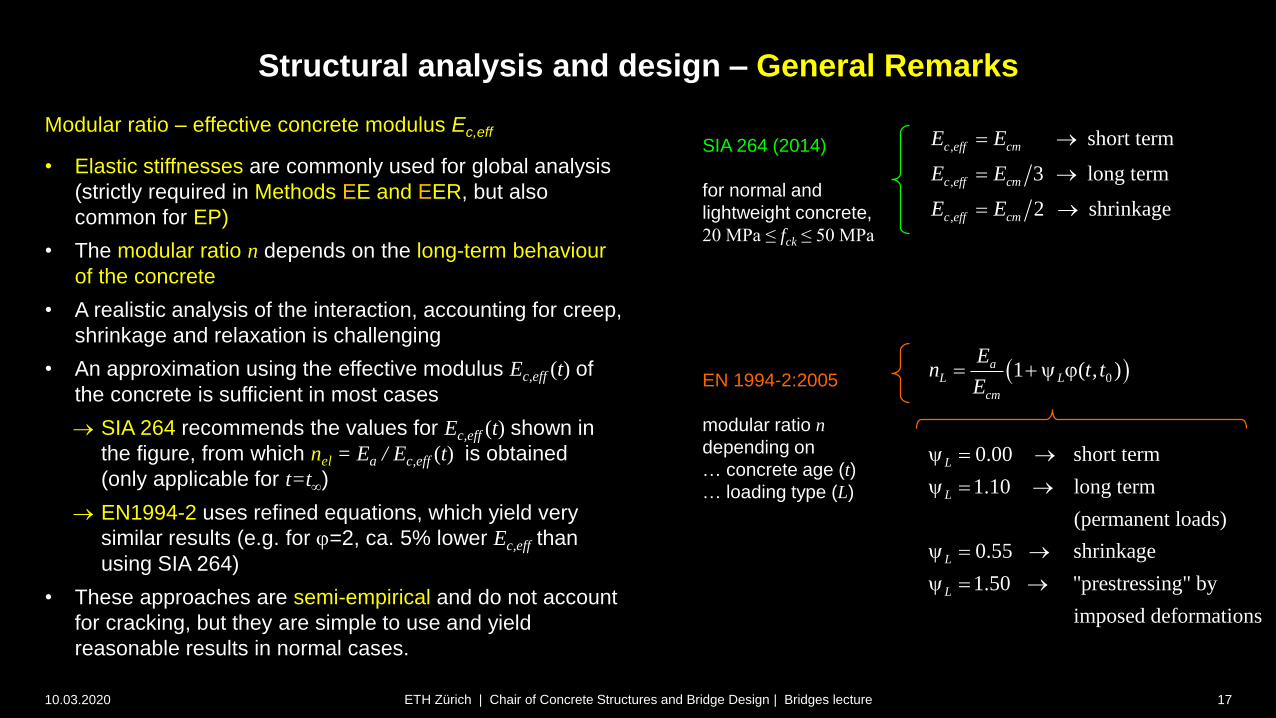
Modular ratio – effective concrete modulus Ec,eff
• Elastic stiffnesses are commonly used for global analysis
(strictly required in Methods EE and EER, but also
common for EP)
• The modular ratio n depends on the long-term behaviour
of the concrete
• A realistic analysis of the interaction, accounting for creep,
shrinkage and relaxation is challenging
• An approximation using the effective modulus Ec,eff (t) of
the concrete is sufficient in most cases
SIA 264 recommends the values for Ec,eff (t) shown in
the figure, from which nel = Ea / Ec,eff (t) is obtained
(only applicable for t=t)
EN1994-2 uses refined equations, which yield very
similar results (e.g. for j=2, ca. 5% lower Ec,eff than
using SIA 264)
• These approaches are semi-empirical and do not account
for cracking, but they are simple to use and yield
reasonable results in normal cases.
,
,
,
short term
3 long term
2 shrinkage
c eff cm
c eff cm
c eff cm
E E
E E
E E
01 ( , )aL L
cm
En t t
E j
0.00 short term
1.10 long term
(permanent loads)
0.55 shrinkage
1.50 "prestressing" by
imposed deformations
L
L
L
L
SIA 264 (2014)
for normal and
lightweight concrete,
20 MPa ≤ fck ≤ 50 MPa
EN 1994-2:2005
modular ratio n
depending on
… concrete age (t)
… loading type (L)
Structural analysis and design – General Remarks
10.03.2020 18ETH Zürich | Chair of Concrete Structures and Bridge Design | Bridges lecture
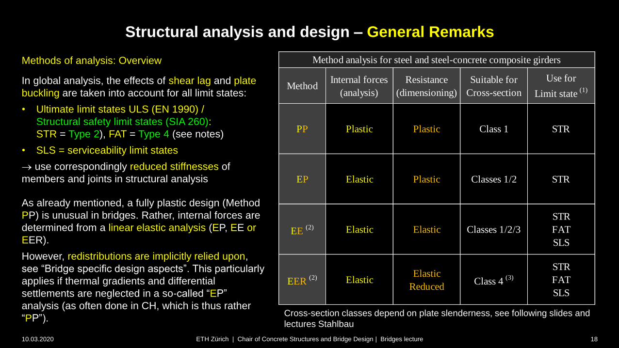
Methods of analysis: Overview
In global analysis, the effects of shear lag and plate
buckling are taken into account for all limit states:
• Ultimate limit states ULS (EN 1990) /
Structural safety limit states (SIA 260):
STR = Type 2), FAT = Type 4 (see notes)
• SLS = serviceability limit states
use correspondingly reduced stiffnesses of
members and joints in structural analysis
As already mentioned, a fully plastic design (Method
PP) is unusual in bridges. Rather, internal forces are
determined from a linear elastic analysis (EP, EE or
EER).
However, redistributions are implicitly relied upon,
see “Bridge specific design aspects”. This particularly
applies if thermal gradients and differential
settlements are neglected in a so-called “EP”
analysis (as often done in CH, which is thus rather
“PP”).
MethodInternal forces
(analysis)
Resistance
(dimensioning)
Suitable for
Cross-section
Use for
Limit state (1)
PP Plastic Plastic Class 1 STR
EP Elastic Plastic Classes 1/2 STR
EE (2) Elastic Elastic Classes 1/2/3
STR
FAT
SLS
EER (2) Elastic
Elastic
ReducedClass 4
(3)
STR
FAT
SLS
Method analysis for steel and steel-concrete composite girders
Cross-section classes depend on plate slenderness, see following slides and
lectures Stahlbau

Structural analysis and design – General Remarks
10.03.2020 19ETH Zürich | Chair of Concrete Structures and Bridge Design | Bridges lecture
Methods of analysis: Overview
Table remarks (see notes page for details)
1) Abbreviations used hereafter:
ULS STR = structural safety, limit state type 2
(failure of structure or structural member)
ULS FAT = structural safety, limit state type 2
(fatigue)
2) For a strictly elastic verification, all actions must
be considered (including thermal gradients,
differential settlements etc.
3) EN 1993-1-5: 2006 (General rules - Plated
structural elements) requires to account for the
effect of plate buckling on stiffnesses if the
effective cross-sectional area of an element in
compression is less than ρlim = 0.5 times its gross
cross-sectional area. This is rarely the case (such
plates are structurally inefficient). If it applies to
webs, it is usually neglected since they have a
minor effect on the bending stiffness of the cross-
section (shear deformations are neglected). Cross-section classes depend on plate slenderness, see following slides and
lectures Stahlbau
MethodInternal forces
(analysis)
Resistance
(dimensioning)
Suitable for
Cross-section
Use for
Limit state (1)
PP Plastic Plastic Class 1 STR
EP Elastic Plastic Classes 1/2 STR
EE (2) Elastic Elastic Classes 1/2/3
STR
FAT
SLS
EER (2) Elastic
Elastic
ReducedClass 4
(3)
STR
FAT
SLS
Method analysis for steel and steel-concrete composite girders

Structural analysis and design – General Remarks
10.03.2020 20ETH Zürich | Chair of Concrete Structures and Bridge Design | Bridges lecture
Overview of required checks in ultimate limit
state design
shear
resistance
bending
resistancebending-shear
resistance
longitudinal shear
resistance (shear connection)
• fatigue resistance (including shear connection)
• resistance to point load (patch loading)
• buckling in compressed flanges or webs
• lateral buckling for open cross-section during erection or over support

Superstructure / Girder bridges
10.03.2020 21
Design and erection
Steel and steel-concrete composite girders
Structural analysis and design – Staged construction
ETH Zürich | Chair of Concrete Structures and Bridge Design | Bridges lecture

z
xy
Structural analysis and design – General Remarks
10.03.2020 22ETH Zürich | Chair of Concrete Structures and Bridge Design | Bridges lecture
Staged construction
• Construction is often staged
account for staged construction in analysis
challenging in composite girders
since the cross-section typically changes and
time-dependent effects need to be considered
(concrete creeps and shrinks, steel does not)
• In many situations, it is useful to subdivide the
internal actions into forces in the
steel girder Ma, Na (tension positive)
concrete deck Mc, Nc (compression positive)
(including reinforcement)
0aM
sx
aT
z
xyaM
cM
aN
cN
MN
aT
cT
Tca
aaa
ex
cz
az
Strains and stresses for loads applied to steel girders (N=0 shown)
Strains and stresses for loads applied to composite section
aaT
0
, 0 0 f 0or a
a a a a
N N
M a N NMM
0a
0for
c
c c
a
a a
a
ca
a c
N
M a N
N N
M a N
M N
M
NaM
T: Centroid of composite sectionTa: Centroid of steel sectionTc: Centroid of concrete section (incl. reinforcement)
sxex
T: Centroid of composite sectionTa: Centroid of steel section
MN
0aN

Structural analysis and design – General Remarks
10.03.2020 23
Calculation of action effects in staged construction
• A global, staged linear elastic analysis is usually
carried out
• Cracking of the deck and long-term effects are
considered by using appropriate modular ratios
n = Es / Ec,eff (t) to determine member stiffnesses
• Actions are generally applied to static systems with
varying supports and cross-sections.
• Typically
1. The steel girders are erected and carry their
self-weight (often with temporary shoring)
2. The concrete deck is cast on a formwork
supported by the steel girders (often with
temporary shoring)
3. The formwork and temporary shoring are
removed (apply negative reactions!)
4. The superimposed dead loads are applied
(long-term concrete stiffness, see Method EE)
5. The variable loads are applied (short-term
concrete stiffness, see Method EE)
ETH Zürich | Chair of Concrete Structures and Bridge Design | Bridges lecture
1. Erection of steel girders with temporary shoring
2. Casting of concrete deck (on steel girders)
3. Removal of formwork and temporary shoring
4. Superimposed dead load (surfacing, parapets, …)
5. Envelope of variable / transient loads
(traffic, wind, further short-term loads)
3 2 for shrinkageel a cm a cmn E E E E
el a cmn E E
span (M>0) support (M<0)
span (M>0) support (M<0)
span (M>0) support (M<0)
sum of
permanent
loads
negative reactions of temporary supports

Structural analysis and design – General Remarks
10.03.2020 24
Calculation of action effects in staged construction
• Essentially:
steel girders carry loads alone until concrete
deck has hardened and connection steel-
concrete is established (stages 1+2)
composite girders carry all loads thereafter
(stages 3 ff), considering concrete creep by an
appropriate modular ratio
• The total action effects are obtained as the sum of
action effects due to each action, applied to the
static system (supports, cross-sections) active at
the time of their application
• If temporary supports are removed, it is essential
to apply the (negative) sum of their support
reactions from previous load stages as loads to the
static system at their removal
• This general procedure is not unique to steel and
composite bridges, but used for the staged
analysis of any structure
ETH Zürich | Chair of Concrete Structures and Bridge Design | Bridges lecture
1. Erection of steel girders with temporary shoring
2. Casting of concrete deck (on steel girders)
3. Removal of formwork and temporary shoring
4. Superimposed dead load (surfacing, parapets, …)
5. Envelope of variable / transient loads
(traffic, wind, further short-term loads)
3 2 for shrinkageel a cm a cmn E E E E
el a cmn E E
span (M>0) support (M<0)
span (M>0) support (M<0)
span (M>0) support (M<0)
negative reactions of temporary supports
Superstructure / Girder bridges
10.03.2020 25
Design and erection
Steel and steel-concrete composite girders
Structural analysis and design – Elastic-plastic design (EP)
ETH Zürich | Chair of Concrete Structures and Bridge Design | Bridges lecture

Structural analysis and design – Elastic-plastic design (EP)
10.03.2020 26
Elastic-plastic design (Method EP)
• For compact sections (class 1 or 2), the structural safety (limit
state type 2 = STR) may basically be verified using the plastic
bending resistance of the cross-section (Method EP), using
MEd = MEd (G)+MEd (Q) total action effects
(sum of action effects due to each action in appropriate
system)
MRd = Mpl,Rd = full plastic resistance of section
This essentially corresponds to the ULS verification of
concrete bridges based on an elastic (staged) global analysis
Typically, compact sections are present
in the span of composite girders (deck in compression,
steel in tension)
over supports in girders with double composite action
(concrete bottom slab)
• Activating the full Mpl,Rd requires rotation capacity not only in
the section under consideration in some cases, even if the
section is compact, Mpl,Rd needs to be reduced by 10% (see
following slides)
ETH Zürich | Chair of Concrete Structures and Bridge Design | Bridges lecture
negative reactions of temporary supports
MEd (G)
MEd (Q)
MEd
Structural analysis and design – Elastic-plastic design (EP)
10.03.2020 27ETH Zürich | Chair of Concrete Structures and Bridge Design | Bridges lecture
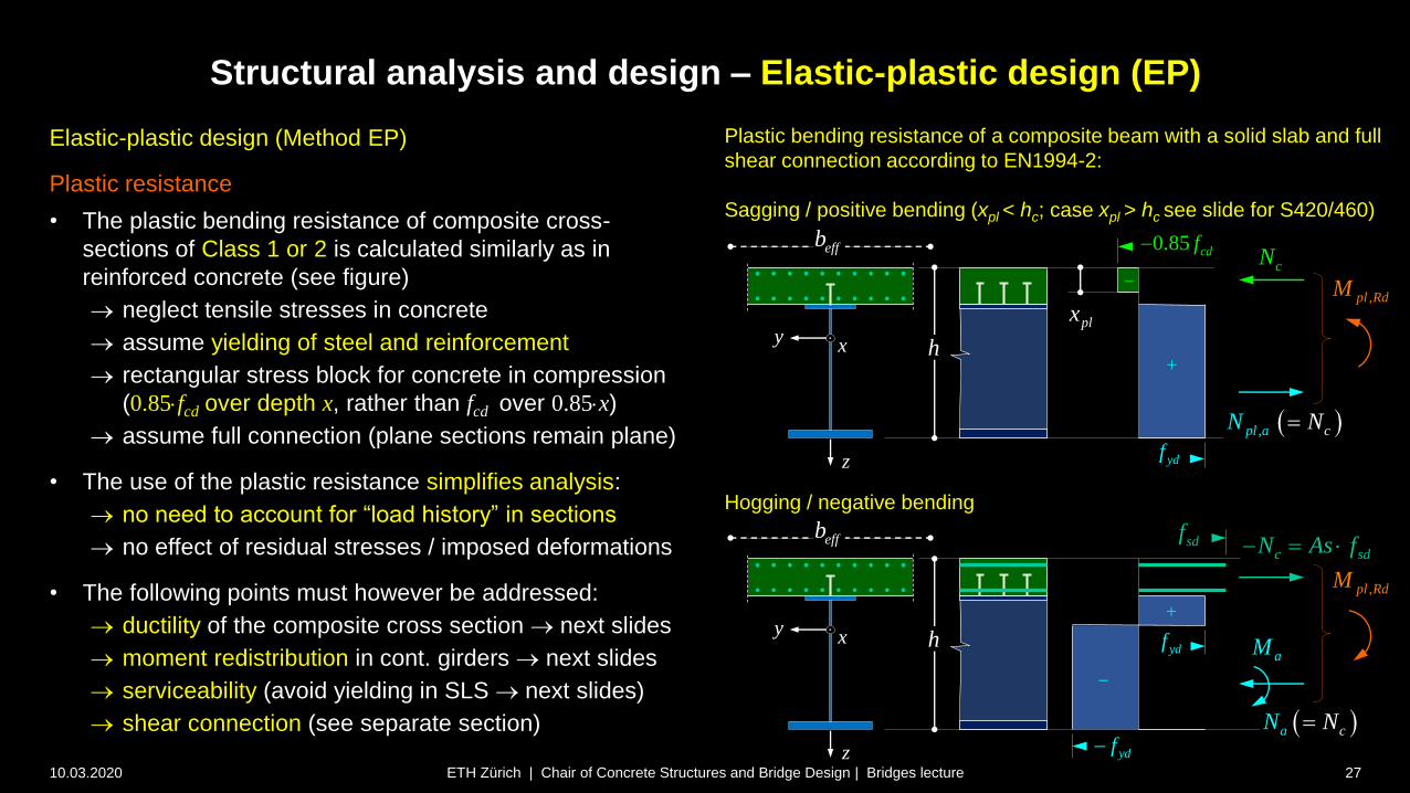
Plastic bending resistance of a composite beam with a solid slab and full
shear connection according to EN1994-2:
Sagging / positive bending (xpl < hc; case xpl > hc see slide for S420/460)
z
xy
0.85 cdf
,pl RdM
effb
h
ydf
cN
plx
, cpl aN N
z
xy
,pl RdM
effb
h
ydf
ydf
caN N
aM
Elastic-plastic design (Method EP)
Plastic resistance
• The plastic bending resistance of composite cross-
sections of Class 1 or 2 is calculated similarly as in
reinforced concrete (see figure)
neglect tensile stresses in concrete
assume yielding of steel and reinforcement
rectangular stress block for concrete in compression
(0.85fcd over depth x, rather than fcd over 0.85x)
assume full connection (plane sections remain plane)
• The use of the plastic resistance simplifies analysis:
no need to account for “load history” in sections
no effect of residual stresses / imposed deformations
• The following points must however be addressed:
ductility of the composite cross section next slides
moment redistribution in cont. girders next slides
serviceability (avoid yielding in SLS next slides)
shear connection (see separate section)
sdfc sdN As f
Hogging / negative bending

Structural analysis and design – Elastic-plastic design (EP)
10.03.2020 28ETH Zürich | Chair of Concrete Structures and Bridge Design | Bridges lecture
Elastic-plastic design (Method EP)
Plastic resistance
• In order to reach the full plastic resistance Mpl,Rd, significant
(theoretically infinite) curvature and hence, inelastic rotations, are
required
• The rotations required to reach Mpl,Rd at midspan of a continuous girder
generally may require inelastic rotations in other parts of the girder,
particularly over supports.
• This particularly applies to girders that are not propped during
construction (steel girders carry wet concrete over full span), see
figure: Larger inelastic rotations are required in to reach Mpl,Rd
• To avoid problems related to rotation capacity, EN1994-2 requires to
reduce the bending resistance to MRd 0.9Mpl,Rd if:
the sections over adjacent supports are not compact (i.e. class 3 or
4 rather than 1 or 2), wich is often the case
the adjacent spans are much longer or shorter, i.e. if lmin / lmax < 0.6
• For more detailed information see notes.
Typical moment-curvature relationships of composite
girders (adapted from Lebet and Hirt, Steel Bridges):
tot
totel
el
pl
pl
[Lebet and Hirt]
Structural analysis and design – Elastic-plastic design (EP)
10.03.2020 29ETH Zürich | Chair of Concrete Structures and Bridge Design | Bridges lecture
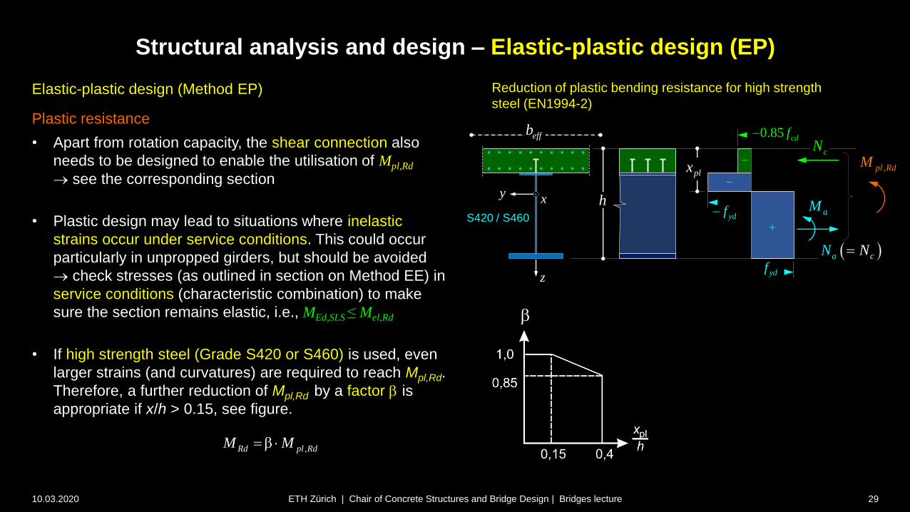
Elastic-plastic design (Method EP)
Plastic resistance
• Apart from rotation capacity, the shear connection also
needs to be designed to enable the utilisation of Mpl,Rd
see the corresponding section
• Plastic design may lead to situations where inelastic
strains occur under service conditions. This could occur
particularly in unpropped girders, but should be avoided
check stresses (as outlined in section on Method EE) in
service conditions (characteristic combination) to make
sure the section remains elastic, i.e., MEd,SLS ≤ Mel,Rd
• If high strength steel (Grade S420 or S460) is used, even
larger strains (and curvatures) are required to reach Mpl,Rd.
Therefore, a further reduction of Mpl,Rd by a factor is
appropriate if x/h > 0.15, see figure.
Reduction of plastic bending resistance for high strength
steel (EN1994-2)
z
xy
0.85 cdf
,pl RdM
h
ydf
ydf
cN
plx
caN N
aMS420 / S460
effb
,Rd pl RdM M
Superstructure / Girder bridges
10.03.2020 30
Design and erection
Steel and steel-concrete composite girders
Structural analysis and design – Elastic design (EE, EER)
ETH Zürich | Chair of Concrete Structures and Bridge Design | Bridges lecture

3 2 for shrinkageel a cm a cmn E E E E
Structural analysis and design – Elastic design (EE, EER)
10.03.2020 31
Elastic design (EE, EER)
• If the relevant cross-sections are not compact
(Class 3 or 4), Method EP cannot be used
Elastic resistance Mel,Rd must be used (Method
EE: full steel section, EER: reduced steel section)
• Since Mel,Rd is defined by reaching the design
yield stress in any fibre of the cross-section, the
load history in the sections needs to be
considered, i.e., rather than merely adding up
bending moments and normal forces, the stresses
throughout the section need to be summed up
• A global, staged linear elastic analysis is thus
carried out to
… determine action effects (as in Method EP)
… determine stresses in cross-sections
• The total stresses in each fibre of a cross-section
are obtained as the sum of the stresses caused
by each action (load step) acting on the static
system (supports, cross-sections) active at the
time of its application.
ETH Zürich | Chair of Concrete Structures and Bridge Design | Bridges lecture
1. Erection of steel girders with temporary shoring
2. Casting of concrete deck (on steel girders)
3. Removal of formwork and temporary shoring
4. Superimposed dead load (surfacing, parapets, …)
5. Envelope of variable / transient loads
(traffic, wind, further short-term loads)
el a cmn E E
span (M>0) support (M<0)
span (M>0) support (M<0)
span (M>0) support (M<0)
negative reactions of temporary supports

Structural analysis and design – Elastic design (EE, EER)
10.03.2020 32
Elastic design (EE, EER)
• Note that while Mel,Rd follows from the
steel, concrete and reinforcement stresses
(sa,Ed, sc,Ed and ss,Ed ) by integration over
the section, the stresses cannot be
determined from Mel,Rd (not even by
iteration) since they depend on the load
history.
ETH Zürich | Chair of Concrete Structures and Bridge Design | Bridges lecture
negative reactions of temporary supports
MEd (G)
MEd (Q)
MEd
sa,Ed
sc,Ed
ss,Edel a cmn E E
span (M>0) support (M<0)
integration
not uniquely
defined unless
load history is
considered

z
xy
Structural analysis and design – Elastic design (EE, EER)
10.03.2020 33ETH Zürich | Chair of Concrete Structures and Bridge Design | Bridges lecture
z
xy
aT
T
(a) Stresses – girder unpropped during construction
(b) Stresses – girder totally propped during construction
self-weight
(steel+concrete)
steel alone
permanent
loads
transient
loads
total
stresses
self-weight
(steel+concrete)
composite girder
permanent
loads
transient
loads
total
stresses
,
0.85 ckEd c
c
fs
,
y
Ed a
y
fs
,
y
Ed a
y
fs
,
y
Ed a
y
fs
,
y
Ed a
y
fs
,
0.85 ckEd c
c
fs
Elastic design (EE, EER)
• The stresses in steel, concrete and
reinforcement (sa,Ed, sc,Ed and ss,Ed ) depend
on the construction sequencing
• In particular, as illustrated in the figure, there
are significant differences between
a bridge unpropped during construction
(steel girders carry formwork and weight of
concrete deck at casting)
a bridge totally propped during construction
(deck cast on formwork supported by
independent falsework / shoring)
• The elastic resistance Mel,Rd is reached when
the steel reaches the design yield stress
sa,Ed fy /a or the concrete reaches a nominal
stress of sc,Ed 0.85fcd 0.85fck /c
• steel is more likely governing in case (a),
concrete in case (b)
T

Structural analysis and design – Elastic design (EE, EER)
10.03.2020 34ETH Zürich | Chair of Concrete Structures and Bridge Design | Bridges lecture
Elastic design (EE, EER)
Elastic stiffnesses
• On this and the following slide, the
considered sections and modular
ratios recommended by SIA 264
are summarised. composite
ael
cm
En
E
steel
composite
3 ael
cm
En
E
composite
2 ael
cm
En
E
loads during erection
(self weight of steel, deck
formwork and concrete)
long term loads
(wearing surface, removed shoring
support reactions)
shrinkage
short term loads
(traffic load, wind , etc.)
Span / sagging moments
(deck in compression)
My
My
My
My

Structural analysis and design – Elastic design (EE, EER)
10.03.2020 35ETH Zürich | Chair of Concrete Structures and Bridge Design | Bridges lecture
Elastic design (EE, EER)
Elastic stiffnesses
• On this and the following slide, the
considered sections and modular
ratios recommended by SIA 264
are summarised.
• In case of double composite
action, concrete in compression
(top or bottom slab) is considered
with the appropriate modular ratio
(see span)
steel and
reinforcement
steel loads during erection
(self weight of steel, deck
formwork and concrete)
all further loads
(unless uncracked behaviour
is considered for specific
checks)
Intermediate supports / hogging moments
deck in tension, cracked concrete neglected
stiffness of tension chord or bare
reinforcement (linear = simpler)
steel, bottom slab and
deck reinforcement
1 3 ael
cm
En
E
My
My
steel, deck and bottom
slab reinforcement
1 3 ael
cm
En
E
Usual case of double composite action (unusual for sagging moments)
My
My
Superstructure / Girder bridges
10.03.2020 36
Design and erection
Steel and steel-concrete composite girders
Structural analysis and design – Fatigue
ETH Zürich | Chair of Concrete Structures and Bridge Design | Bridges lecture

Structural analysis and design – Specific aspects
10.03.2020 37ETH Zürich | Chair of Concrete Structures and Bridge Design | Bridges lecture
Fatigue
• Fatigue is highly relevant in steel and composite bridges, as
it often governs the design (plate thicknesses, details). Here,
some basic aspects are discussed; for more details, see
lectures Stahlbau
• Fatigue is particularly important in the design of railway
bridges, and must be considered in detail already in
conceptual design. It is also important when assessing
existing railway bridges, which are typically older than road
bridges (network built earlier), e.g. photo (built 1859)
• Fatigue safety is verified for nominal stress ranges caused
by the fatigue loads. However, additional effects (often not
accounted for in structural analysis, such as imposed or
restrained deformations, secondary elements or inadequate
welding (visible defects or invisible residual stresses) may
cause stresses that can be even more critical
consider fatigue in conceptual design
select appropriate details
ensure proper execution (welding)

Structural analysis and design – Specific aspects
10.03.2020 38ETH Zürich | Chair of Concrete Structures and Bridge Design | Bridges lecture
Fatigue – Case Study
Main Girder
(Haupträger)
Floor Beam
(Querträger)
Deck Stringers
(Sek. Längsträger)
Stiffeners / Ribs
(Querrippen)Observed fatigue
cracks at welded
stiffeners
(Coating impedes
crack detection by
naked eye)
Initiation point
of fatigue crack
Structural analysis and design – Specific aspects
10.03.2020 39ETH Zürich | Chair of Concrete Structures and Bridge Design | Bridges lecture
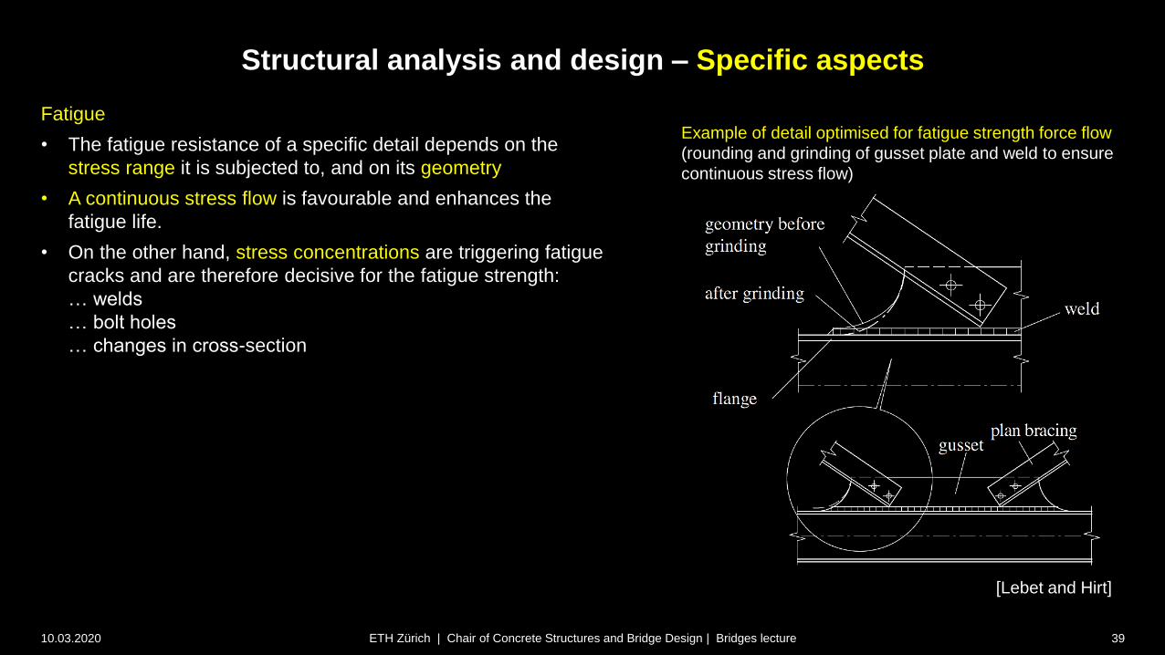
Fatigue
• The fatigue resistance of a specific detail depends on the
stress range it is subjected to, and on its geometry
• A continuous stress flow is favourable and enhances the
fatigue life.
• On the other hand, stress concentrations are triggering fatigue
cracks and are therefore decisive for the fatigue strength:
… welds
… bolt holes
… changes in cross-section
Example of detail optimised for fatigue strength force flow
(rounding and grinding of gusset plate and weld to ensure
continuous stress flow)
[Lebet and Hirt]
Structural analysis and design – Specific aspects
10.03.2020 40ETH Zürich | Chair of Concrete Structures and Bridge Design | Bridges lecture
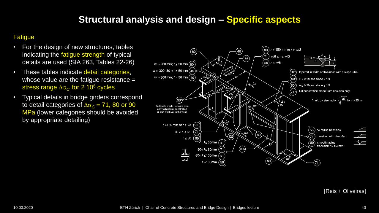
Fatigue
• For the design of new structures, tables
indicating the fatigue strength of typical
details are used (SIA 263, Tables 22-26)
• These tables indicate detail categories,
whose value are the fatigue resistance =
stress range DsC for 2106 cycles
• Typical details in bridge girders correspond
to detail categories of DsC 71, 80 or 90
MPa (lower categories should be avoided
by appropriate detailing)
[Reis + Oliveiras]
Structural analysis and design – Specific aspects
10.03.2020 41ETH Zürich | Chair of Concrete Structures and Bridge Design | Bridges lecture
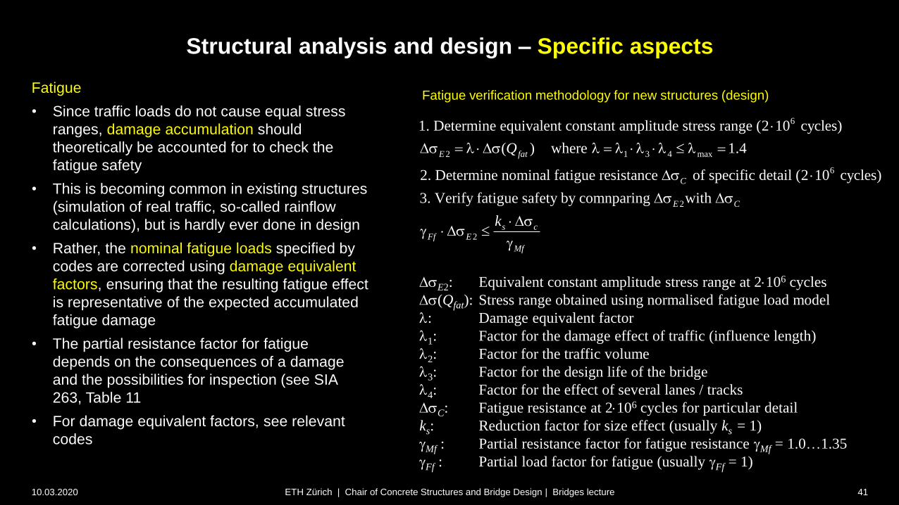
Fatigue
• Since traffic loads do not cause equal stress
ranges, damage accumulation should
theoretically be accounted for to check the
fatigue safety
• This is becoming common in existing structures
(simulation of real traffic, so-called rainflow
calculations), but is hardly ever done in design
• Rather, the nominal fatigue loads specified by
codes are corrected using damage equivalent
factors, ensuring that the resulting fatigue effect
is representative of the expected accumulated
fatigue damage
• The partial resistance factor for fatigue
depends on the consequences of a damage
and the possibilities for inspection (see SIA
263, Table 11
• For damage equivalent factors, see relevant
codes
DsE2: Equivalent constant amplitude stress range at 2106 cycles
Ds(Qfat): Stress range obtained using normalised fatigue load model
l: Damage equivalent factor
l1: Factor for the damage effect of traffic (influence length)
l2: Factor for the traffic volume
l3: Factor for the design life of the bridge
l4: Factor for the effect of several lanes / tracks
DsC: Fatigue resistance at 2106 cycles for particular detail
ks: Reduction factor for size effect (usually ks = 1)
Mf : Partial resistance factor for fatigue resistance Mf = 1.0…1.35
Ff : Partial load factor for fatigue (usually Ff = 1)
6
2 1 3 4 max
6
1. Determine equivalent constant amplitude stress range (2 10 cycles)
( ) where 1.4
2. Determine nominal fatigue resistance of specific detail (2 10 cycles)
3. Verify fati
E fat
C
Q
Ds l Ds l l l l l
Ds
2
2
gue safety by comnparing with E C
s cFf E
Mf
k
Ds Ds
Ds Ds
Fatigue verification methodology for new structures (design)

Superstructure / Girder bridges
10.03.2020 42
Design and erection
Steel and steel-concrete composite girders
Structural analysis and design – Shear Connection
ETH Zürich | Chair of Concrete Structures and Bridge Design | Bridges lecture

10.03.2020 43ETH Zürich | Chair of Concrete Structures and Bridge Design | Bridges lecture
Structural analysis and design – Shear Connection
10.03.2020 44ETH Zürich | Chair of Concrete Structures and Bridge Design | Bridges lecture
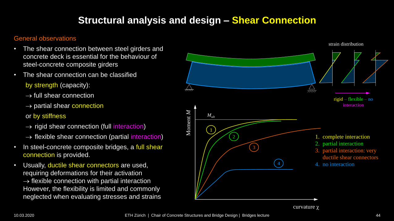
General observations
• The shear connection between steel girders and
concrete deck is essential for the behaviour of
steel-concrete composite girders
• The shear connection can be classified
by strength (capacity):
full shear connection
partial shear connection
or by stiffness
rigid shear connection (full interaction)
flexible shear connection (partial interaction)
• In steel-concrete composite bridges, a full shear
connection is provided.
• Usually, ductile shear connectors are used,
requiring deformations for their activation
flexible connection with partial interaction
However, the flexibility is limited and commonly
neglected when evaluating stresses and strains
rigid – flexible – no
interaction
curvature
Mo
men
t M Mult
1
2
3
4
1. complete interaction
2. partial interaction
3. partial interaction: very
ductile shear connectors
4. no interaction
strain distribution

Structural analysis and design – Shear Connection
10.03.2020 45ETH Zürich | Chair of Concrete Structures and Bridge Design | Bridges lecture
inf
inf
s
inf
( ) ( ) d d ( ) ( )d 0
d ( )( ) ( ) ( )d
d
dM dMd,
d
(
d d
( ) ( )d( )
( ))
z
xz s s x
zs
z
xxz s s
z
y y yx zx z
y
y
y
z sxz
y
z
s
ss
z s
z b z x z b z z
zz b z b z z
x
M
bV S z
V zzz V
I x x x I I
S z z z zb
zz I
s
s
s s
z
xy
dx xs s
zx
xs
xs
xzinfz sz
dx
zV
yM
Linear elastic behaviour – Homogeneous sections
• Assuming a uniform distribution of the shear stresses
over the width b of the cross-section, the distribution of
the vertical shear stresses zx can be approximated in
prismatic bars by the well-known formula illustrated in
the figure
• Derivation see lectures Mechanik and Baustatik):
consider infinitesimal element of length dx,
horizontal cut at depth zs
horizontal equilibrium on free body below zs yields xz
theorem of associated shear stresses: zx = xz
• A parabolic distribution of the shear stresses zx(z)
(resp. of the shear flow b(z)zx(z) if b varies) is obtained.
• The resulting shear stresses are not meaningful in wide
flanges (assumption of constant vertical shear stresses
over width not reasonable)
Linear elastic, homogeneous section (e.g. steel)
(pure bending My , N = Mz = 0)
a

Structural analysis and design – Shear Connection
10.03.2020 46ETH Zürich | Chair of Concrete Structures and Bridge Design | Bridges lecture
inf
( )
inf
( )
inf
( )
( ) ( ) d d ( , ) d 0
d ( , )
1
( )( )
(
( ) ( ) dd
dM dMd1 1,
d d d
d( )
)
y
z i sx
z
xz s s x
z b zs
z
xxz s
i
s
z b zs
y y x zx z
yi yi yi
z
i s
z b zs
z s
s y
z b z x y z A
y zz b z A
x
M V zzz V
n I x x n x I n
A V S z
b
I
zS z zzn I
s
s
s s
Linear elastic behaviour – Composite sections
• Using transformed section properties (ideelle
Querschnittswerte, subscript “i”)
the shear stresses in composite sections consisting of
materials with different moduli of elasticity or even
cracked over a part of the depth can be treated
accordingly, using the modular ratio
• In a cracked concrete section (see figure), the shear
stresses in the cracked region can only change at the
reinforcing bar layers (zero tensile stresses in concrete)
zx (resp. b(z)zx(z)) parabolic over depth c of the
compression zone, constant below until reinforcement
Linear elastic, cracked reinforced concrete section
(pure bending My , N = Mz = 0)
z
xy
xs zx
dsx sxs ssxs
xzinfz sz
dx
zV
yMc
c
( , )( , )
aEn n y z
E y z
2
d
d d, ,i c yi
i
A
A AnA I zn A n
Structural analysis and design – Shear Connection
10.03.2020 47ETH Zürich | Chair of Concrete Structures and Bridge Design | Bridges lecture
( )sup
( )sup
( )sup
( ) ( ) d d ( , ) d 0
d ( , )( ) ( ) d
d
dM dMd1 1 1,
d d d
d(
( )( ))
( )
z ci sxz s
s yi
zs
xz s s x
z b z
zs
xxz s s
z b z
y y yx zx z
yi yi yi
zs
ci s
z b z
V
z b z x y z A
y zz b z A
x
M V zzz V
n I x x n x I n I
I
AS
S zzz z
b zn
s
s
s s
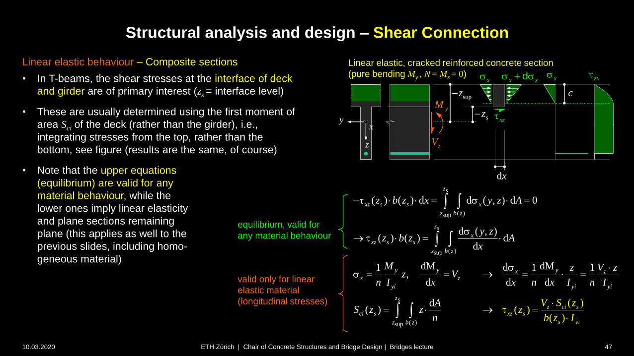
Linear elastic behaviour – Composite sections
• In T-beams, the shear stresses at the interface of deck
and girder are of primary interest (zs = interface level)
• These are usually determined using the first moment of
area Sci of the deck (rather than the girder), i.e.,
integrating stresses from the top, rather than the
bottom, see figure (results are the same, of course)
• Note that the upper equations
(equilibrium) are valid for any
material behaviour, while the
lower ones imply linear elasticity
and plane sections remaining
plane (this applies as well to the
previous slides, including homo-
geneous material)
Linear elastic, cracked reinforced concrete section
(pure bending My , N = Mz = 0)
z
xy
xs zx
xz
supz
sz
dx
zV
yMc
equilibrium, valid for
any material behaviour
valid only for linear
elastic material
(longitudinal stresses)
x xs sdxs
Structural analysis and design – Shear Connection
10.03.2020 48ETH Zürich | Chair of Concrete Structures and Bridge Design | Bridges lecture
( )sup
( )sup
( )sup
( ) ( ) d d ( , ) d 0
d ( , )( ) ( ) d
d
dM dMd1 1 1,
d d d
d(
( )( ))
( )
z ci sxz s
s yi
zs
xz s s x
z b z
zs
xxz s s
z b z
y y yx zx z
yi yi yi
zs
ci s
z b z
V
z b z x y z A
y zz b z A
x
M V zzz V
n I x x n x I n I
I
AS
S zzz z
b zn
s
s
s s
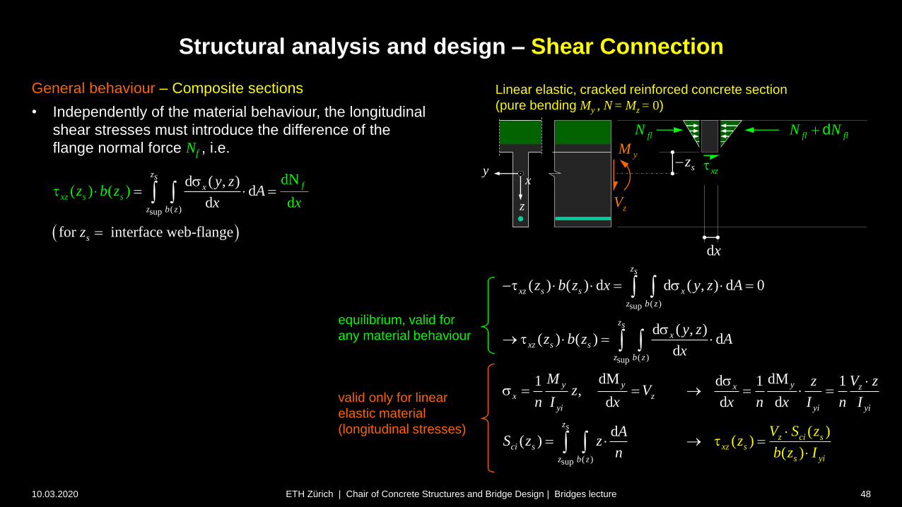
General behaviour – Composite sections
• Independently of the material behaviour, the longitudinal
shear stresses must introduce the difference of the
flange normal force Nf , i.e.
Linear elastic, cracked reinforced concrete section
(pure bending My , N = Mz = 0)
z
xy xzsz
dx
zV
yM
equilibrium, valid for
any material behaviour
valid only for linear
elastic material
(longitudinal stresses)
( )sup
d ( , )d
d d
for interface web-flange
dN( ) ( )
zs
x
z
f
xz s
b
s
s
zx
z b zx
y zA
z
s
fl flN N dflN

Structural analysis and design – Shear Connection
10.03.2020 49ETH Zürich | Chair of Concrete Structures and Bridge Design | Bridges lecture
z
xy
z
xy
, ,, x cx a ss , ,, zx czx a
, ,, x cx a ss , ,, zx czx a Linear elastic steel-concrete composite section, positive My
(N = Mz = 0)
Linear elastic steel-concrete composite section, negative My
(N = Mz = 0)
Linear elastic behaviour – Steel-concrete composite sections
• Accordingly, in steel-concrete composite sections, the
longitudinal shear at the interface between deck and steel
girder is decisive
• The relevant shear stresses (resp. shear forces per unit
length) to be transferred along the interface are thus
obtained using the first moment of area of the deck
(without flange of steel girder!), i.e.
• The contribution of the deck reinforcement is commonly
included in the values “c” of the concrete deck (“c” =
reinforced concrete), and often neglected for positive
bending (reinforcement in compression)
supz
sz
supz
sz
( )sup
( )( ) ( )
d( )z ci s
xz s s
yi
zs
ci s
z b z
V S zz b z
I
AS z z
n

Structural analysis and design – Shear Connection
10.03.2020 50ETH Zürich | Chair of Concrete Structures and Bridge Design | Bridges lecture
z
xy
z
xy
, ,, x cx a ss , ,, zx czx a
, ,, x cx a ss , ,, zx czx a Linear elastic steel-concrete composite section, positive My
(N = Mz = 0)
Linear elastic steel-concrete composite section, negative My
(N = Mz = 0)
Linear elastic behaviour – Steel-concrete composite sections
• Again, the equation
only applies for linear elastic behaviour
if bending resistances exceeding the elastic resistance
Mel,Rd are activated (e.g. Method EP, utilisation of full
plastic resistance Mpl,Rd), application of the above
equation may be unsafe
supz
sz
supz
sz
( )sup
( )( ) ( )
d( )z ci s
xz s s
yi
zs
ci s
z b z
V S zz b z
I
AS z z
n
Structural analysis and design – Shear Connection
10.03.2020 51ETH Zürich | Chair of Concrete Structures and Bridge Design | Bridges lecture
z
xy
z
xy
Linear elastic steel-concrete composite section, positive My
(N = Mz = 0)
Linear elastic steel-concrete composite section, negative My
(N = Mz = 0)
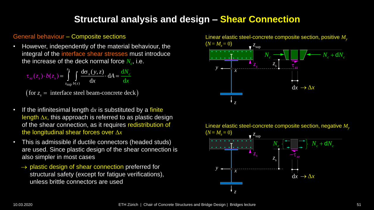
General behaviour – Composite sections
• However, independently of the material behaviour, the
integral of the interface shear stresses must introduce
the increase of the deck normal force Nc, i.e.
• If the infinitesimal length dx is substituted by a finite
length Dx, this approach is referred to as plastic design
of the shear connection, as it requires redistribution of
the longitudinal shear forces over Dx
• This is admissible if ductile connectors (headed studs)
are used. Since plastic design of the shear connection is
also simpler in most cases
plastic design of shear connection preferred for
structural safety (except for fatigue verifications),
unless brittle connectors are used
supz
sz
supz
sz
( )sup
k
d
d
d ( , )d
d
for interface steel beam-conc
)
rete d c
(
e
( )
z
xc
sx
z b
s
z
z
s sz bx
z AN
x
y z
z
s
xz
dx
c cN N dcN
sz
xzsz
c cN N dcN
dx
x D
x D

V : Vertical shear force after steel to concrete connection is established
Sc: First moment of area of the deck relative to the neutral axis of the
composite section (with subscript i: transformed section)
Ib: Second moment of area of the composite section, calculated with
the appropriate modular ratio nel
nel: Elastic modular ratio (1…3)Ea / Ecm
Structural analysis and design – Shear Connection
10.03.2020 52ETH Zürich | Chair of Concrete Structures and Bridge Design | Bridges lecture
Elastic design of shear connection
• Elastic design of the shear connection is suitable
for design situations resp. regions of the girder
where the composite section remains elastic
fatigue verifications
elastic design (EE, EER)
elastic-plastic design (EP) outside regions
where the elastic resistance Mel,Rd is exceeded
• As derived on the previous slides, the longitudinal
shear force per unit length vel is proportional to the
vertical shear force V
• The section properties are commonly determined
considering uncracked concrete (and neglecting
the reinforcement), even in cracked areas (see
notes). Therefore, rather than determining the
transformed moment of area Sci, one may simply
use Sc of the gross concrete section, divided by nel.
,
1Ed ci Ed cL Ed xz
e
cci
elb b l
V S V Sv b
I I nn
SAS z z A
n n
dd
larger bottom
flange area
longitudinal
shear
V
vL
V
vL

Structural analysis and design – Shear Connection
10.03.2020 53ETH Zürich | Chair of Concrete Structures and Bridge Design | Bridges lecture
Elastic design of shear connection
• Since different modular ratios nel apply for short-
term and long-term loads, the design value of the
longitudinal shear in each section is the sum of a
number of cases j
• If headed studs with a design shear resistance PRd
per stud are used (determination of PRd see behind),
the required number of studs per unit length of the
girder is obtained by dividing the longitudinal shear
force by PRd
• To avoid excessive slip, the resistance of the shear
connectors has to be reduced by 25% under certain
conditions; the slide shows the condition of EN1994-
2. For further details, see headed studs
, ,
, , ,
, ,
Ed j c j
L Ed L Ed j
j i b j el j
V Sv v
I n
nv,el: number of shear connectors
eL: longitudinal spacing of connectors
PRd: design shear resistance of one shear connector (depending on
elastic / plastic calculation of section, see behind)
larger bottom
flange area
,
, , , ,
,
and 0.75 . .0.75
v el L EkLL Ek Rd
v e d
v el L
L l
d
LRd R
En
P
nv vev P i e
e n e P
V
vL
V
vL
longitudinal
shear

Structural analysis and design – Shear Connection
10.03.2020 54ETH Zürich | Chair of Concrete Structures and Bridge Design | Bridges lecture
Elastic design of shear connection
• The longitudinal shear force diagram must basically
be enveloped by the provided resistance
• Commonly, it is tolerated that the design shear force
vL,Ed exceeds the resistance vL,Rd by 10% at certain
points, provided that the total resisting force in the
corresponding zone is larger than the total design
force vL,Rd,1
vL,Rd,2
vL,Rd,i
vL,Rd,1vL,Rd,2
larger bottom
flange area
V
vL
V
vL

Structural analysis and design – Shear Connection
10.03.2020 55ETH Zürich | Chair of Concrete Structures and Bridge Design | Bridges lecture
Elastic design of shear connection
• As illustrated in the figure and mentioned previously, the
longitudinal shear forces
may be unsafe if bending resistances exceeding the elastic
resistance Mel,Rd are activated (derivation of the equation implies
a linear elastic distribution of the cross-section)
If an elastic design of the shear connection is carried out, but a
bending resistance MRd > Mel,Rd is used (Method EP), it must be
verified that the shear connection can transfer the normal force
increase Nc,d Nc,el in the deck required for reaching MRd over the
length xpl,, i.e.
• This is particularly relevant in unpropped girders, where the deck
normal force Nc,el under Mel,Rd is considerably lower than at Mpl,Rd
(concrete weight is carried fully by the steel section without
causing any contribution to Nc,el)
vL, ,
,
p dl
c d c el
v pl
R
N N
xn
P
,Ed ci Ed c
L Ed xz
b b el
V S V Sv b
I I n
[Lebet + Hirt]
nv,pl : number of shear connectors per unit length
Nc,d : normal force in the deck at section with Mel,Rd
Nc,el : normal force in the deck corresponding to Mel,Rd
PRd : shear resistance of the stud
xpl
Structural analysis and design – Shear Connection
10.03.2020 56ETH Zürich | Chair of Concrete Structures and Bridge Design | Bridges lecture
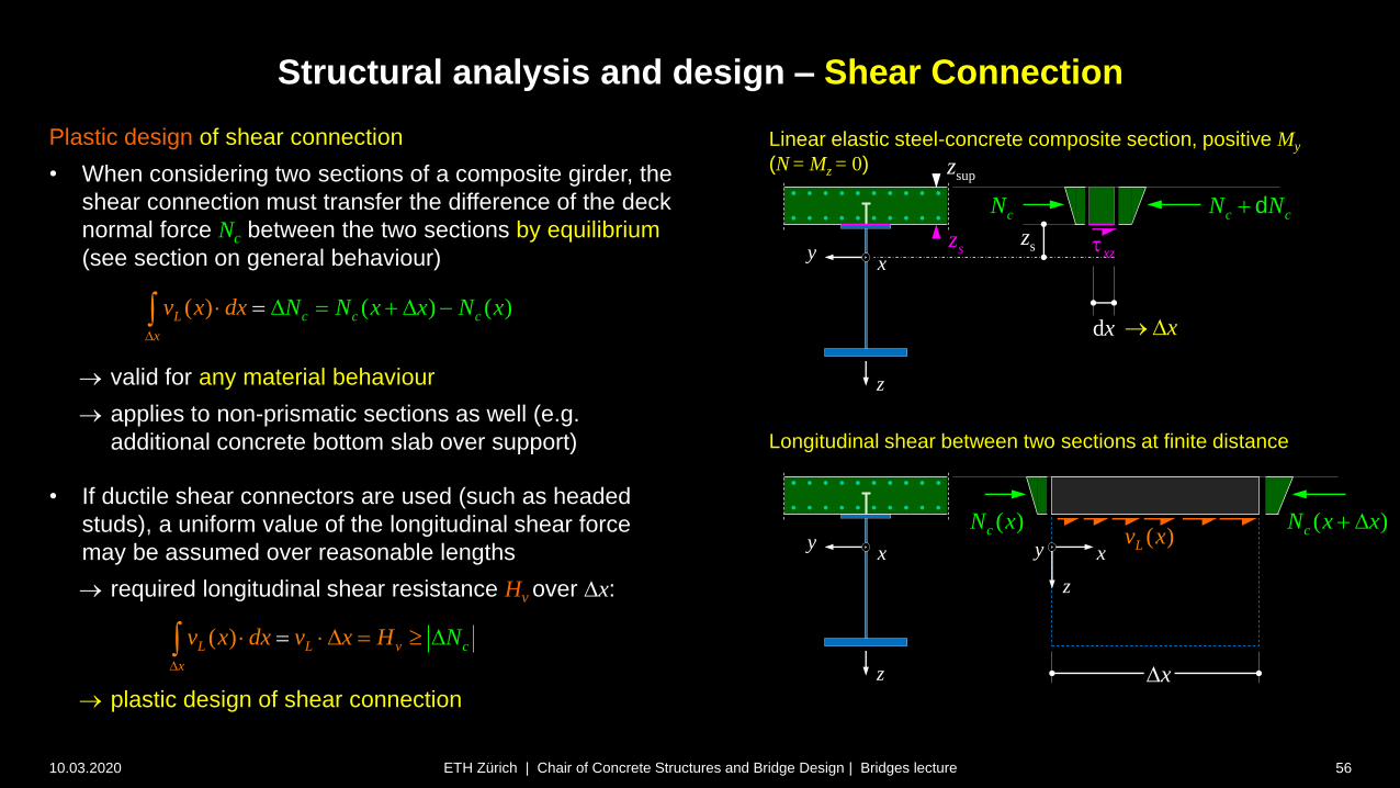
Plastic design of shear connection
• When considering two sections of a composite girder, the
shear connection must transfer the difference of the deck
normal force Nc between the two sections by equilibrium
(see section on general behaviour)
valid for any material behaviour
applies to non-prismatic sections as well (e.g.
additional concrete bottom slab over support)
• If ductile shear connectors are used (such as headed
studs), a uniform value of the longitudinal shear force
may be assumed over reasonable lengths
required longitudinal shear resistance Hv over Dx:
plastic design of shear connection
( )( () )c cL c
x
v Nx N N x x xdxD
D D
Longitudinal shear between two sections at finite distance
z
xy
supz
szxz
dx
c cN N dcN
sz
x D
z
xy ( )Lv x
( )cN x x D( )cN x
z
xy
xD
Linear elastic steel-concrete composite section, positive My
(N = Mz = 0)
( ) cL L v
x
v x dx v x H ND
D D
Structural analysis and design – Shear Connection
10.03.2020 57ETH Zürich | Chair of Concrete Structures and Bridge Design | Bridges lecture
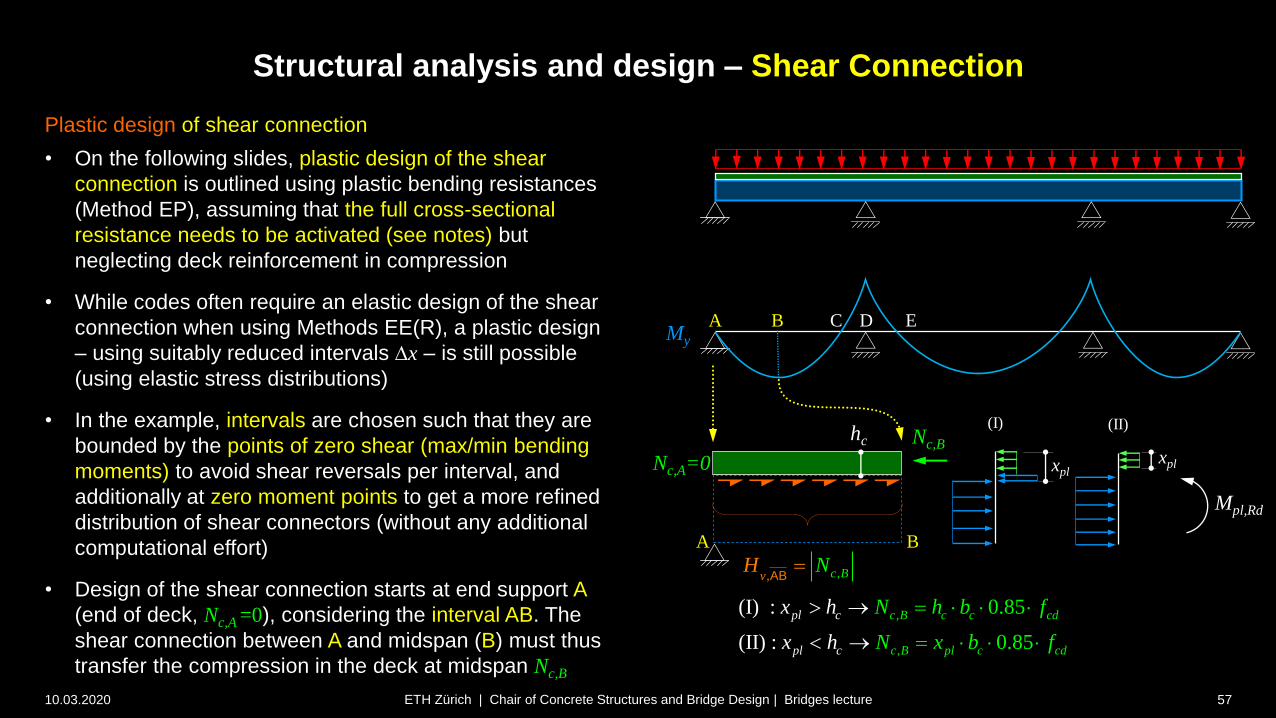
Plastic design of shear connection
• On the following slides, plastic design of the shear
connection is outlined using plastic bending resistances
(Method EP), assuming that the full cross-sectional
resistance needs to be activated (see notes) but
neglecting deck reinforcement in compression
• While codes often require an elastic design of the shear
connection when using Methods EE(R), a plastic design
– using suitably reduced intervals Dx – is still possible
(using elastic stress distributions)
• In the example, intervals are chosen such that they are
bounded by the points of zero shear (max/min bending
moments) to avoid shear reversals per interval, and
additionally at zero moment points to get a more refined
distribution of shear connectors (without any additional
computational effort)
• Design of the shear connection starts at end support A
(end of deck, Nc,A =0), considering the interval AB. The
shear connection between A and midspan (B) must thus
transfer the compression in the deck at midspan Nc,B
My
A B DC
A B
Nc,B
Nc,A=0 xpl
Mpl,Rd
(I)
xpl
(II)hc
,
,
(I) :
(II) :
0.
85
85
0.
c B c c cd
c B pl c cd
pl c
pl c
N h b f
N x
x h
fx bh
, ,Bv cH NAB
E
Structural analysis and design – Shear Connection
10.03.2020 58ETH Zürich | Chair of Concrete Structures and Bridge Design | Bridges lecture
My
A B DC
B C
Nc,Bhc Nc,C=0
, ,Bv cH NBC
E
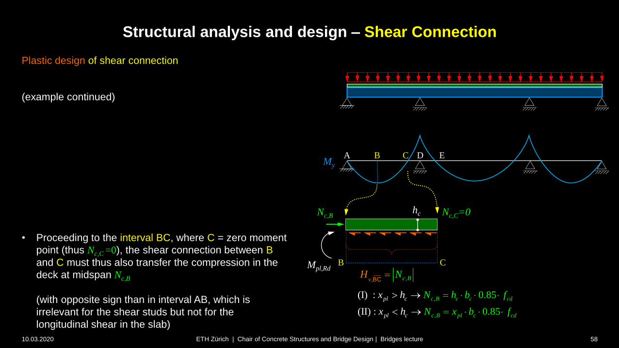
Plastic design of shear connection
(example continued)
• Proceeding to the interval BC, where C = zero moment
point (thus Nc,C =0), the shear connection between B
and C must thus also transfer the compression in the
deck at midspan Nc,B
(with opposite sign than in interval AB, which is
irrelevant for the shear studs but not for the
longitudinal shear in the slab)
,
,
(I) :
(II) :
0.
85
85
0.
c B c c cd
c B pl c cd
pl c
pl c
N h b f
N x
x h
fx bh
Mpl,Rd
Structural analysis and design – Shear Connection
10.03.2020 59ETH Zürich | Chair of Concrete Structures and Bridge Design | Bridges lecture
My
A B DC
C D
hc Nc,D
,c D s sdN A f
Nc,D=-As fsd
Mpl,Rd
Nc,C=0
, ,Dv cH NCD
E
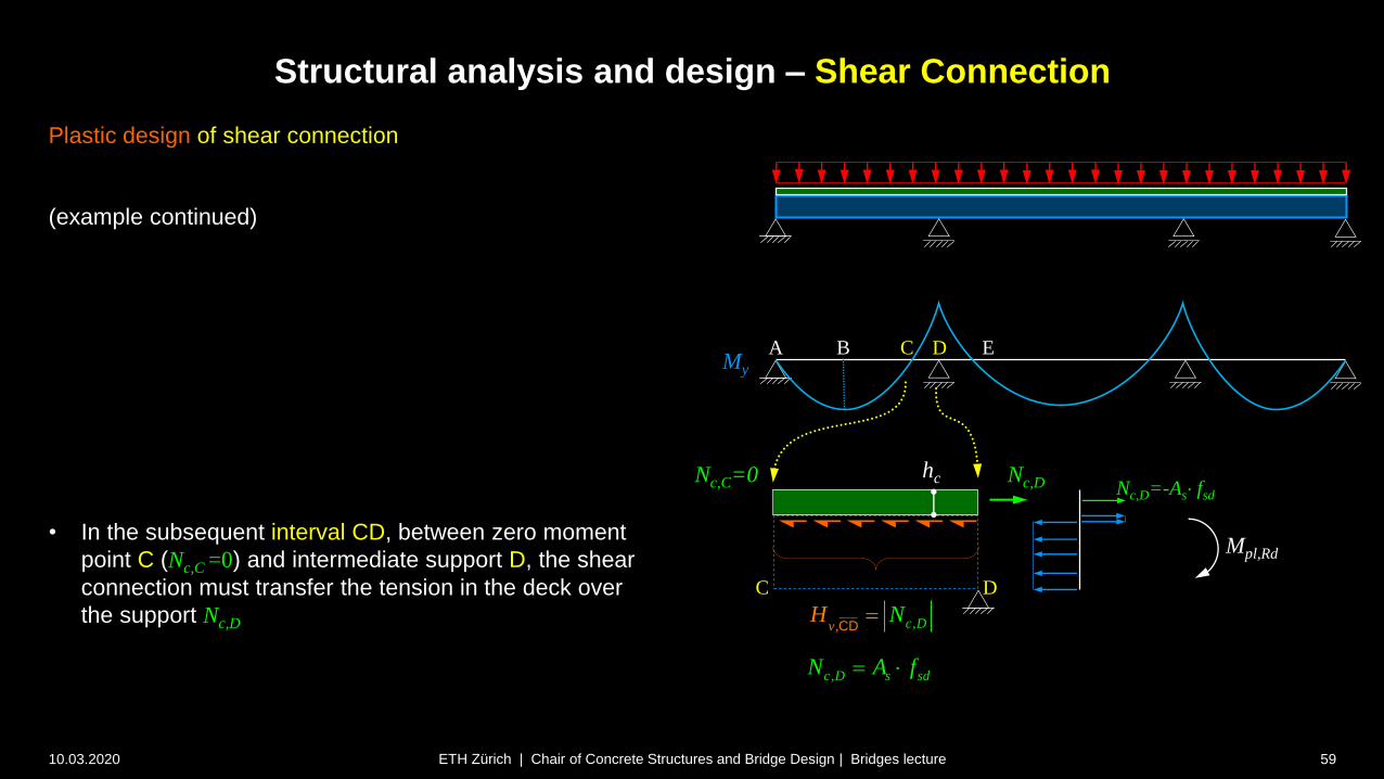
Plastic design of shear connection
(example continued)
• In the subsequent interval CD, between zero moment
point C (Nc,C =0) and intermediate support D, the shear
connection must transfer the tension in the deck over
the support Nc,D

Structural analysis and design – Shear Connection
10.03.2020 60ETH Zürich | Chair of Concrete Structures and Bridge Design | Bridges lecture
My
A B DC
D E
E
hc
, ,Dv cH NDE
Nc,D Nc,E=0
,c D s sdN A f
Plastic design of shear connection
(example continued)
• In the interval DE, between the intermediate support D
and the zero moment point E in the inner span (Nc,E =0),
the shear connection must also transfer Nc,D
(with opposite sign than in interval AB, which is
irrelevant for the shear studs but not for the longitudinal
shear in the slab)
Mpl,Rd

Structural analysis and design – Shear Connection
10.03.2020 61ETH Zürich | Chair of Concrete Structures and Bridge Design | Bridges lecture
Plastic design of shear connection
• The total number of shear connectors per interval is
obtained simply by dividing the longitudinal shear force
per interval by the resistance per connector, e.g. for AB:
• Where appropriate, these connectors should be
distributed roughly according to the linear elastic shear
force diagram over the interval (illustrated for the end
span AB, see notes)
adequate behaviour in SLS
less additional connectors required by subsequent
fatigue verification (elastic calculation)
• The intervals used in the example should be further
subdivided at
large concentrated forces (e.g. prestressing, truss
node), see next slide
substantial changes in cross-section (e.g. bottom slab
end in double composite action)
A B
LAB / 2 LAB / 2
25% nv,pl,AB 75% nv,pl,AB
My
A B DC E
,
, ,
v
v plRd
Hn
P
AB
AB
Vz

Structural analysis and design – Shear Connection
10.03.2020 62ETH Zürich | Chair of Concrete Structures and Bridge Design | Bridges lecture
Longitudinal shear forces due to (concentrated)
horizontal loads
• Horizontal loads and imposed deformations,
applied to the deck or steel section, cause
longitudinal shear forces (transfer to
composite section)
• This applies in cases such as:
prestressing (anchor forces P)
shrinkage or temperature difference
between concrete deck and steel beam
horizontal forces applied e.g. through truss
nodes (difference in normal force DN)
bending moments applied e.g. through
non-ideal truss nodes (difference in
bending moment DM )
concentrated longitudinal shear forces
resulting from sudden changes in the
dimensions of the cross-section
[Lebet + Hirt]
Structural analysis and design – Shear Connection
10.03.2020 63ETH Zürich | Chair of Concrete Structures and Bridge Design | Bridges lecture
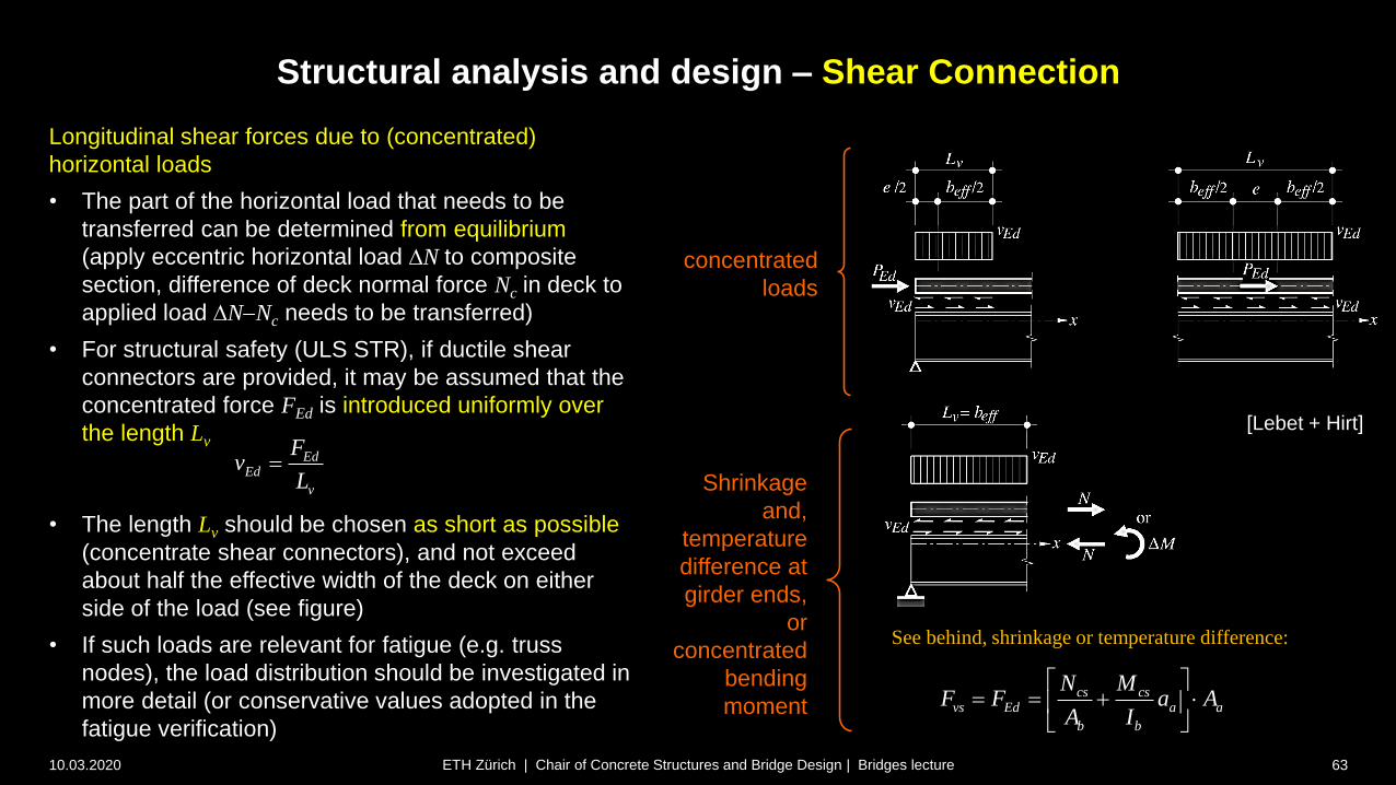
Longitudinal shear forces due to (concentrated)
horizontal loads
• The part of the horizontal load that needs to be
transferred can be determined from equilibrium
(apply eccentric horizontal load DN to composite
section, difference of deck normal force Nc in deck to
applied load DNNc needs to be transferred)
• For structural safety (ULS STR), if ductile shear
connectors are provided, it may be assumed that the
concentrated force FEd is introduced uniformly over
the length Lv
• The length Lv should be chosen as short as possible
(concentrate shear connectors), and not exceed
about half the effective width of the deck on either
side of the load (see figure)
• If such loads are relevant for fatigue (e.g. truss
nodes), the load distribution should be investigated in
more detail (or conservative values adopted in the
fatigue verification)
EdEd
v
Fv
L
concentrated
loads
Shrinkage
and,
temperature
difference at
girder ends,
or
concentrated
bending
momentcs cs
vs Ed a a
b b
N MF F a A
A I
See behind, shrinkage or temperature difference:
[Lebet + Hirt]
1.5 Dd
0.4 Dd
2.5Dd t
0.2 Dd
3D Dh d
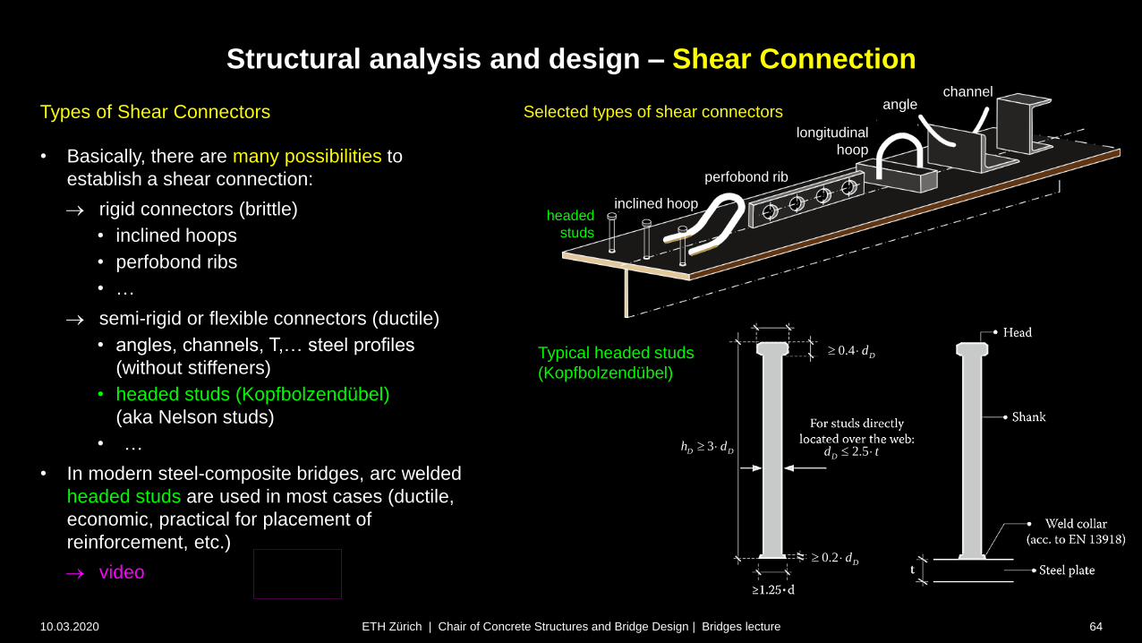
Types of Shear Connectors
• Basically, there are many possibilities to
establish a shear connection:
rigid connectors (brittle)
• inclined hoops
• perfobond ribs
• …
semi-rigid or flexible connectors (ductile)
• angles, channels, T,… steel profiles
(without stiffeners)
• headed studs (Kopfbolzendübel)
(aka Nelson studs)
• …
• In modern steel-composite bridges, arc welded
headed studs are used in most cases (ductile,
economic, practical for placement of
reinforcement, etc.)
video
Structural analysis and design – Shear Connection
10.03.2020 64ETH Zürich | Chair of Concrete Structures and Bridge Design | Bridges lecture
Selected types of shear connectors
Typical headed studs
(Kopfbolzendübel)
headed
studs
inclined hoop
perfobond rib
longitudinal
hoop
anglechannel

2
,
0.29 Dc Rd ck cm
v
dP f E
2,
,
0.8
4
u D DD Rd
v
f dP
Concrete crushing Failure of the stud shank
dD : diameter of the stud shank
fck : characteristic value of concrete cylinder strength
Ecm : mean value of concrete elastic modulus
fu,D : ultimate tensile resistance of the stud steel (typically 450 MPa)
v : resistance factor for the shear connection (v = 1.25)
2310'000 8 in N/mmcm ckE f
Resistance of headed studs
• Headed studs transfer “shear” by a combination of
bending and tension, resulting in a complex behaviour
ductile response with relatively large deformations
resistances determined by testing
• Based on the experimental studies, the ”shear strength”
of headed studs PRd is limited by
… failure of the stud shank at PD,Rd or
… crushing of the concrete at Pc,Rd , i.e.
PRd = min {Pc,Rd; Pc,Rd}
• If tensile forces Ft > 0.1· PRd act in the direction of the
stud (e.g. introduction of transverse bending moment to
web), the shear resistance should be determined from
representative tests (usually not critical)
• Additional provisions to avoid excessive slip apply:
SIA 263: Reduce Pc,Rd by 25% if elastic resistance is
used (Methods EE, EER)
EN1994-2: Shear force per stud must not exceed
0.75 PRd under characteristic loads
Structural analysis and design – Shear Connection
10.03.2020 65ETH Zürich | Chair of Concrete Structures and Bridge Design | Bridges lecture
Design values of PRd per stud [kN] (plastic calculation, fu,D = 450 MPa)
avoid
(unusual)
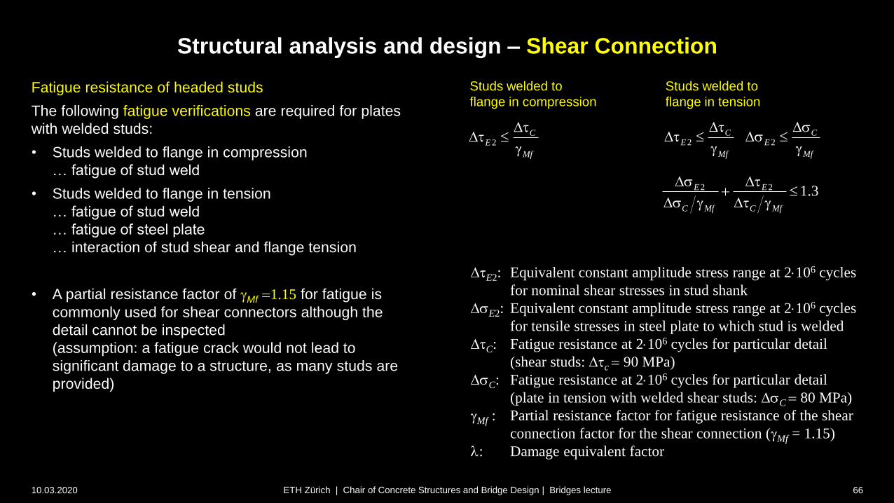
Fatigue resistance of headed studs
The following fatigue verifications are required for plates
with welded studs:
• Studs welded to flange in compression
… fatigue of stud weld
• Studs welded to flange in tension
… fatigue of stud weld
… fatigue of steel plate
… interaction of stud shear and flange tension
• A partial resistance factor of Mf 1.15 for fatigue is
commonly used for shear connectors although the
detail cannot be inspected
(assumption: a fatigue crack would not lead to
significant damage to a structure, as many studs are
provided)
Structural analysis and design – Shear Connection
10.03.2020 66ETH Zürich | Chair of Concrete Structures and Bridge Design | Bridges lecture
2 2 1.3E E
C Mf C Mf
Ds D
Ds D
Studs welded to
flange in compression
DE2: Equivalent constant amplitude stress range at 2106 cycles
for nominal shear stresses in stud shank
DsE2: Equivalent constant amplitude stress range at 2106 cycles
for tensile stresses in steel plate to which stud is welded
DC: Fatigue resistance at 2106 cycles for particular detail
(shear studs: Dc 90 MPa)
DsC: Fatigue resistance at 2106 cycles for particular detail
(plate in tension with welded shear studs: DsC 80 MPa)
Mf : Partial resistance factor for fatigue resistance of the shear
connection factor for the shear connection (Mf = 1.15)
l: Damage equivalent factor
Studs welded to
flange in tension
2C
E
Mf
DD
2 2
C CE E
Mf Mf
D DsD Ds
10.03.2020 67ETH Zürich | Chair of Concrete Structures and Bridge Design | Bridges lecture
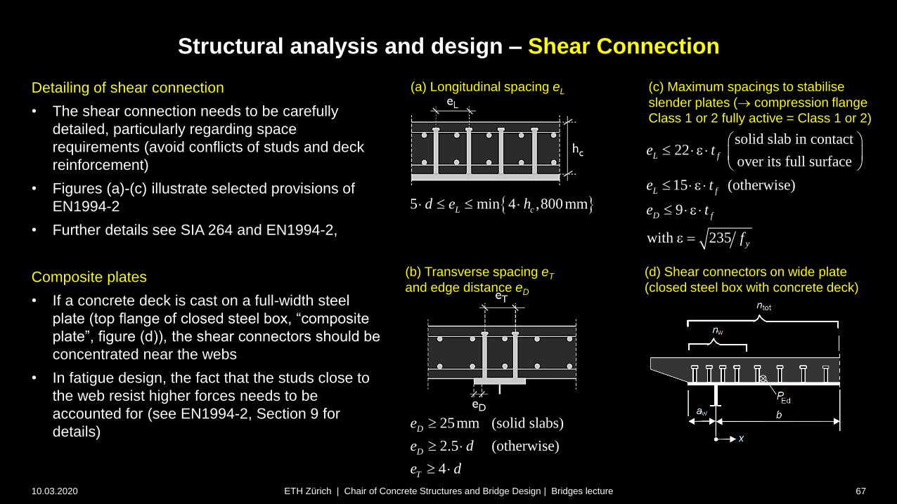
Detailing of shear connection
• The shear connection needs to be carefully
detailed, particularly regarding space
requirements (avoid conflicts of studs and deck
reinforcement)
• Figures (a)-(c) illustrate selected provisions of
EN1994-2
• Further details see SIA 264 and EN1994-2,
Composite plates
• If a concrete deck is cast on a full-width steel
plate (top flange of closed steel box, “composite
plate”, figure (d)), the shear connectors should be
concentrated near the webs
• In fatigue design, the fact that the studs close to
the web resist higher forces needs to be
accounted for (see EN1994-2, Section 9 for
details)
(a) Longitudinal spacing eL
5 min 4 ,800mmL cd e h
25mm (solid slabs)
2.5 (otherwise)
4
D
D
T
e
e d
e d
(c) Maximum spacings to stabilise
slender plates ( compression flange
Class 1 or 2 fully active = Class 1 or 2)
solid slab in contact22
over its full surface
15 (otherwise)
9
with 235
L f
L f
D f
y
e t
e t
e t
f
e
e
e
e
(b) Transverse spacing eT
and edge distance eD
(d) Shear connectors on wide plate
(closed steel box with concrete deck)
Structural analysis and design – Shear Connection
Structural analysis and design – Shear Connection
10.03.2020 68ETH Zürich | Chair of Concrete Structures and Bridge Design | Bridges lecture
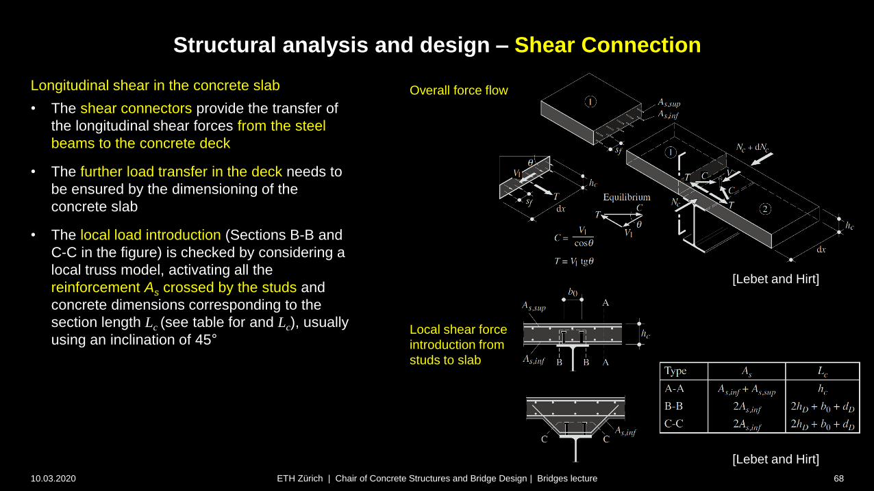
Longitudinal shear in the concrete slab
• The shear connectors provide the transfer of
the longitudinal shear forces from the steel
beams to the concrete deck
• The further load transfer in the deck needs to
be ensured by the dimensioning of the
concrete slab
• The local load introduction (Sections B-B and
C-C in the figure) is checked by considering a
local truss model, activating all the
reinforcement As crossed by the studs and
concrete dimensions corresponding to the
section length Lc (see table for and Lc), usually
using an inclination of 45°
[Lebet and Hirt]
Local shear force
introduction from
studs to slab
Overall force flow
[Lebet and Hirt]
Structural analysis and design – Shear Connection
10.03.2020 69ETH Zürich | Chair of Concrete Structures and Bridge Design | Bridges lecture
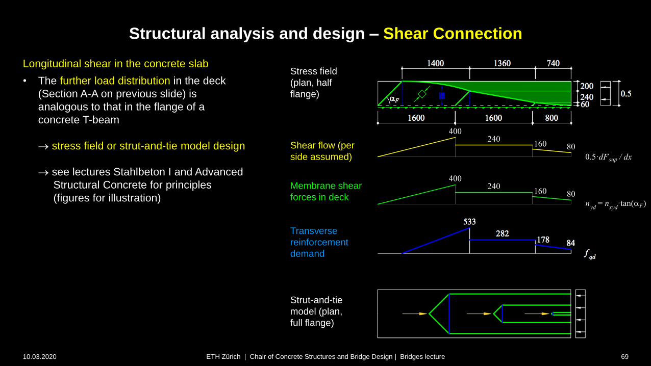
Stress field
(plan, half
flange)
Shear flow (per
side assumed)
Membrane shear
forces in deck
Transverse
reinforcement
demand
Strut-and-tie
model (plan,
full flange)
Longitudinal shear in the concrete slab
• The further load distribution in the deck
(Section A-A on previous slide) is
analogous to that in the flange of a
concrete T-beam
stress field or strut-and-tie model design
see lectures Stahlbeton I and Advanced
Structural Concrete for principles
(figures for illustration)
Structural analysis and design – Shear Connection
10.03.2020 70ETH Zürich | Chair of Concrete Structures and Bridge Design | Bridges lecture
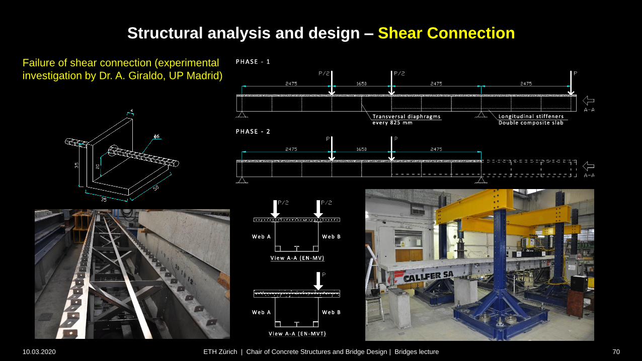
Failure of shear connection (experimental
investigation by Dr. A. Giraldo, UP Madrid)

Structural analysis and design – Shear Connection
10.03.2020 71ETH Zürich | Chair of Concrete Structures and Bridge Design | Bridges lecture
Failure of shear connection (experimental
investigation by Dr. A. Giraldo, UP Madrid)
Superstructure / Girder bridges
10.03.2020 72
Design and erection
Steel and steel-concrete composite girders
Structural analysis and design – Further aspects
ETH Zürich | Chair of Concrete Structures and Bridge Design | Bridges lecture

beff =
25 tw
Structural analysis and design – Shear capacity of composite girders
10.03.2020 73ETH Zürich | Chair of Concrete Structures and Bridge Design | Bridges lecture
Shear Capacity of composite girders
• In the design of steel-concrete composite girders, the
shear capacity is determined for the steel girder
alone (neglecting any contribution of the concrete
deck)
• Webs are often slender to save weight post-critical
shear strength, see lectures Stahlbau (illustrated
schematically in figure)
• While neglecting the concrete deck is conservative, it
may make sense to activate the considerable reserve
capacity provided by the concrete deck in composite
(box girder) bridges with slender webs
the figure shows the extended Cardiff model (see
notes), considering the flange moments of the
composite flange instead of just those of the steel
flange, thereby enhancing the post-critical tension
field in the web
Extended Cardiff model
(see notes and references)
Shear strength of slender web (post-critical behaviour)
,
1
,min
,
1
( , ) ( , )( ) 1
( ', ')( )
y cr crd f w
M y
cr
d f w
M
a b a bV h t t
a bV h t t
s
, ,
1
interior panel
0.9end panel
Rd d d
cr y w
Rd
M
V V V
b tV
s
4
,
2
,
50
25 2.1
0.75 ( )
f
S erf
S erf S y w
cr f
h t
A V
I
f t
l h t
Posts
Structural analysis and design – Specific aspects
10.03.2020 74ETH Zürich | Chair of Concrete Structures and Bridge Design | Bridges lecture
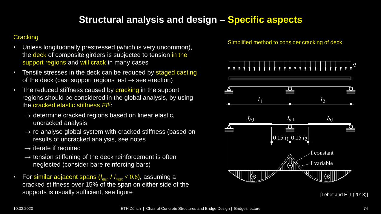
Cracking
• Unless longitudinally prestressed (which is very uncommon),
the deck of composite girders is subjected to tension in the
support regions and will crack in many cases
• Tensile stresses in the deck can be reduced by staged casting
of the deck (cast support regions last see erection)
• The reduced stiffness caused by cracking in the support
regions should be considered in the global analysis, by using
the cracked elastic stiffness EIII:
determine cracked regions based on linear elastic,
uncracked analysis
re-analyse global system with cracked stiffness (based on
results of uncracked analysis, see notes
iterate if required
tension stiffening of the deck reinforcement is often
neglected (consider bare reinforcing bars)
• For similar adjacent spans (lmin / lmax < 0.6), assuming a
cracked stiffness over 15% of the span on either side of the
supports is usually sufficient, see figure [Lebet and Hirt (2013)]
Simplified method to consider cracking of deck
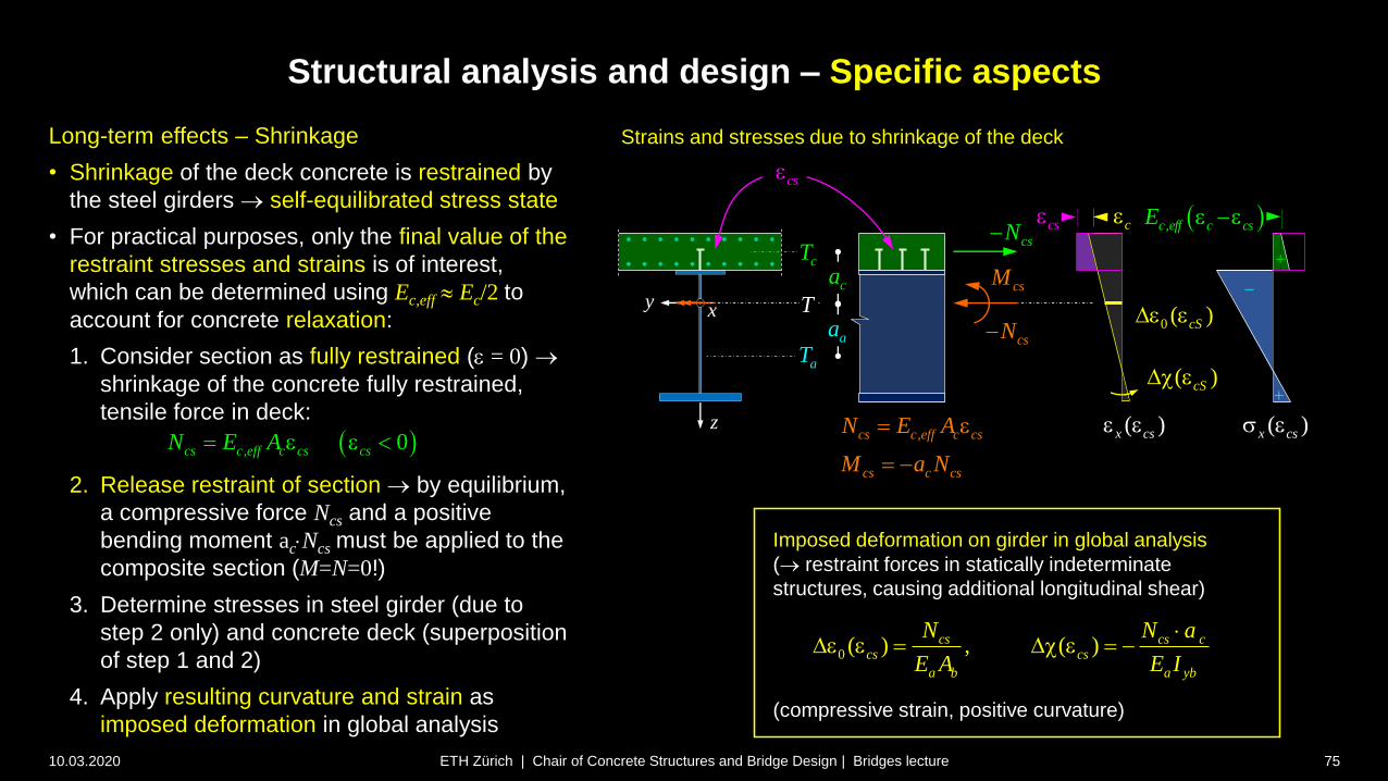
Structural analysis and design – Specific aspects
10.03.2020 75ETH Zürich | Chair of Concrete Structures and Bridge Design | Bridges lecture
Long-term effects – Shrinkage
• Shrinkage of the deck concrete is restrained by
the steel girders self-equilibrated stress state
• For practical purposes, only the final value of the
restraint stresses and strains is of interest,
which can be determined using Ec,eff Ec/2 to
account for concrete relaxation:
1. Consider section as fully restrained (e = 0)
shrinkage of the concrete fully restrained,
tensile force in deck:
2. Release restraint of section by equilibrium,
a compressive force Ncs and a positive
bending moment acNcs must be applied to the
composite section (M=N=0!)
3. Determine stresses in steel girder (due to
step 2 only) and concrete deck (superposition
of step 1 and 2)
4. Apply resulting curvature and strain as
imposed deformation in global analysis
z
xyca
Strains and stresses due to shrinkage of the deck
csN
csN
csM
aT
cT
T
, 0cs c eff c cs csN E A e e
cse
Imposed deformation on girder in global analysis
( restraint forces in statically indeterminate
structures, causing additional longitudinal shear)
(compressive strain, positive curvature)
,cs c eff c cs
cs c cs
N E A
M a N
e
0 ( ) , ( )cs cs ccs cs
a b a yb
N N a
E A E I
De e D e
aa
( )cSD e
0 ( )cSDe e
( )x css e( )x cse e
cse ,c eff c csE e ece

Horizontal force to be transferred at girder ends by
shear connection due to shrinkage
Structural analysis and design – Specific aspects
10.03.2020 76ETH Zürich | Chair of Concrete Structures and Bridge Design | Bridges lecture
Long-term effects – Shrinkage
• Restrained shrinkage causes tension in the deck
and compression in the steel girders
• Typically, tensile stresses of about 1 MPa result in
the deck uncracked unless additional tension
is caused by load
• The corresponding deformations of the composite
section (compressive strain, positive curvature)
are imposed to the girder for global analysis
deformations (sagging) of the girder
restraint in statically indeterminate structures
• At the girder ends, the deck is stress-free
normal force in deck (= normal force in steel
must be introduced shear connection must
resist horizontal force Hvs at girder ends
usually distributed over a length corresponding
to the effective width of the deck (still requires
dense connector layout at girder ends)
• Differential temperature is treated accordingly
(also requires load introduction at girder ends)0 ( ) cs cs
vs a cS a a a
b b
N MH A a A
A I
s e
z
xyca
csN
csN
csM
aT
cT
T
cse
,cs c eff c cs
cs c cs
N E A
M a N
e
aa
0
1( ) cs cs c a
a cS a cs
b b b b
N M a aa N
A I A I
s e
Strains and stresses due to shrinkage of the deck
( )x css e( )x cse e
cse ,c eff c csE e ece
0 aEDe
aa
0 ( )a cSs e

Structural analysis and design – Specific aspects
10.03.2020 77ETH Zürich | Chair of Concrete Structures and Bridge Design | Bridges lecture
Long-term effects – Shrinkage
• The redundant forces (bending moments and shear
forces) can be obtained by applying the primary
moment Mcs and the normal force –Ncs to the girder
(see e.g. Lebet and Hirt, Steel bridges)
• This may however be misleading in case of a plastic
design (Mcs and Ncs are no action effects when
considering the entire girder)
• Alternatively, one may simply impose the
compressive strain and positive curvature caused by
shrinkage to the girder:
• The resulting redundant moments – to be
superimposed with the primary moment to obtain
stresses in the steel girder – are schematically shown
in the figure (smaller in case of cracked deck)
• The corresponding shear forces need to be
considered when designing the shear connection
Redundant moments due to shrinkage, deck uncracked over supports
0 ( ) , ( )cs cs ccs cs
a b a yb
N N a
E A E I
De e D e
( )csD e
( )y csM e
Redundant moments due to shrinkage, deck cracked over supports
( )csD e
( )y csM e
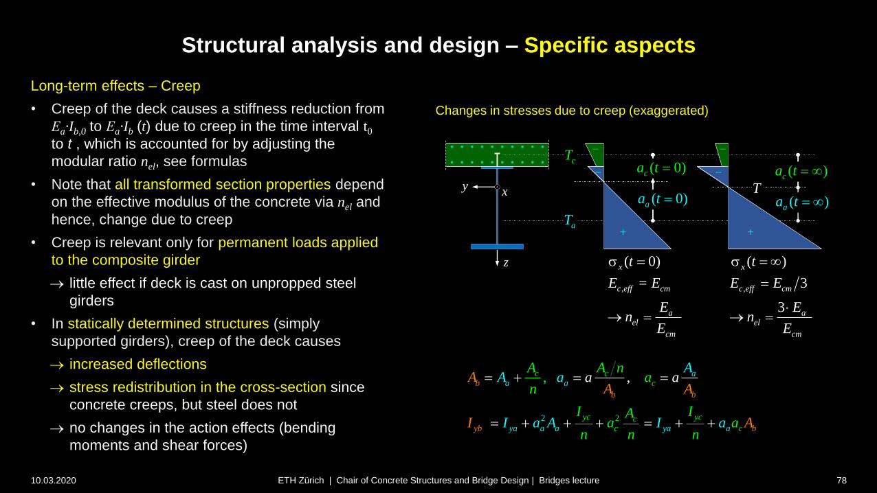
Structural analysis and design – Specific aspects
10.03.2020 78ETH Zürich | Chair of Concrete Structures and Bridge Design | Bridges lecture
Long-term effects – Creep
• Creep of the deck causes a stiffness reduction from
Εa·Ib,0 to Εa·Ib (t) due to creep in the time interval t0
to t , which is accounted for by adjusting the
modular ratio nel, see formulas
• Note that all transformed section properties depend
on the effective modulus of the concrete via nel and
hence, change due to creep
• Creep is relevant only for permanent loads applied
to the composite girder
little effect if deck is cast on unpropped steel
girders
• In statically determined structures (simply
supported girders), creep of the deck causes
increased deflections
stress redistribution in the cross-section since
concrete creeps, but steel does not
no changes in the action effects (bending
moments and shear forces)
Changes in stresses due to creep (exaggerated)
2 2
, , aa a
ya ba
c ccb
yc y
ca ya
b b
b
cccay
AA aA
A
A A naa
n
I IAa aI a I a
n
A
n
aA
I An
z
xy
aT
cT
T
,c eff cm
ael
cm
E = E
E n
E
( 0)x ts ( )x ts
, 3
3
c eff cm
ael
cm
E E
E n
E
( 0)aa t
( 0)ca t
( )aa t
( )ca t
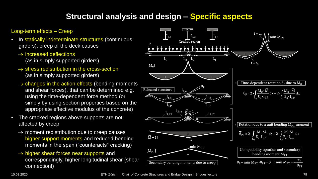
Structural analysis and design – Specific aspects
10.03.2020 79ETH Zürich | Chair of Concrete Structures and Bridge Design | Bridges lecture
Long-term effects – Creep
• In statically indeterminate structures (continuous
girders), creep of the deck causes
increased deflections
(as in simply supported girders)
stress redistribution in the cross-section
(as in simply supported girders)
changes in the action effects (bending moments
and shear forces), that can be determined e.g.
using the time-dependent force method (or
simply by using section properties based on the
appropriate effective modulus of the concrete)
• The cracked regions above supports are not
affected by creep
moment redistribution due to creep causes
higher support moments and reduced bending
moments in the span (“counteracts” cracking)
higher shear forces near supports and
correspondingly, higher longitudinal shear (shear
connection!)
Superstructure / Girder bridges
10.03.2020 80
Design and erection
Steel and steel-concrete composite girders
Construction and erection
ETH Zürich | Chair of Concrete Structures and Bridge Design | Bridges lecture

Steel and composite girders – Construction and erection
10.03.2020 81ETH Zürich | Chair of Concrete Structures and Bridge Design | Bridges lecture
Construction of the concrete slab
• Slab cast in-place
• Slab composed of precast elements
• Slab launched in stages
most common
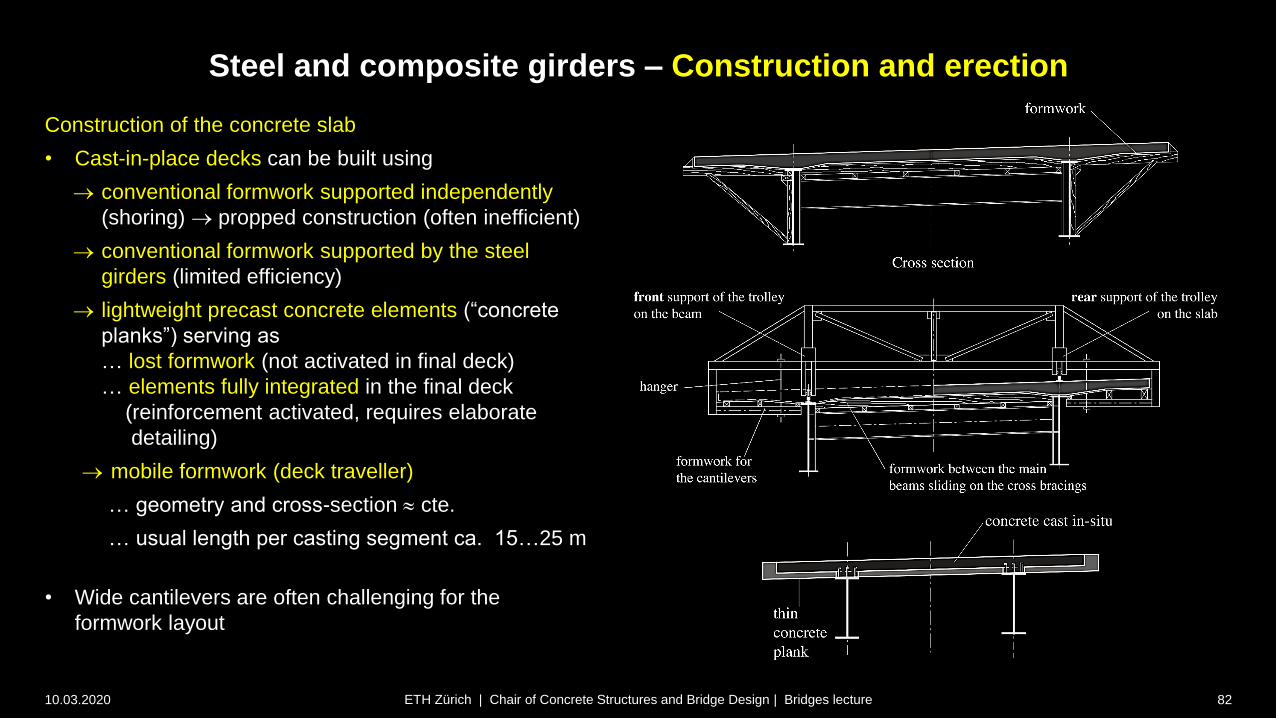
Steel and composite girders – Construction and erection
10.03.2020 82ETH Zürich | Chair of Concrete Structures and Bridge Design | Bridges lecture
Construction of the concrete slab
• Cast-in-place decks can be built using
conventional formwork supported independently
(shoring) propped construction (often inefficient)
conventional formwork supported by the steel
girders (limited efficiency)
lightweight precast concrete elements (“concrete
planks”) serving as
… lost formwork (not activated in final deck)
… elements fully integrated in the final deck
(reinforcement activated, requires elaborate
detailing)
mobile formwork (deck traveller)
… geometry and cross-section cte.
… usual length per casting segment ca. 15…25 m
• Wide cantilevers are often challenging for the
formwork layout
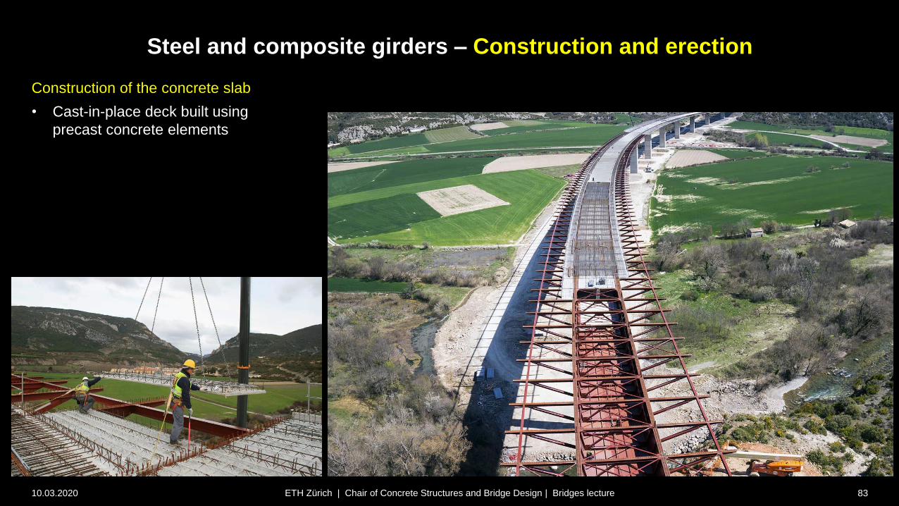
Steel and composite girders – Construction and erection
10.03.2020 83ETH Zürich | Chair of Concrete Structures and Bridge Design | Bridges lecture
Construction of the concrete slab
• Cast-in-place deck built using
precast concrete elements

Steel and composite girders – Construction and erection
10.03.2020 84ETH Zürich | Chair of Concrete Structures and Bridge Design | Bridges lecture
Construction of the concrete slab
Concreting sequence (slab cast in-place)
• The construction sequence of the deck is
highly relevant for
the efficiency of construction
the durability of the deck (cracking)
• Simply supported bridges (single span) up to
ca. 25 m long are usually cast in one stage.
• For longer spans, the weight of the wet
concrete causes high stresses in the steel
girders, which might be critical in SLS and in
an elastic design; furthermore, large
deformations must be compensated by
precamber (higher risk of deviations in
geometry).
• Alternatively, the slab may be cast in stages,
first in the span region and then near the ends.

Steel and composite girders – Construction and erection
10.03.2020 85ETH Zürich | Chair of Concrete Structures and Bridge Design | Bridges lecture
Construction of the concrete slab
Concreting sequence (slab cast in-place)
• The slab in continuous bridges is usually cast
in stages in order to limit the tension stresses
of concrete above intermediate supports.
Sequential casting, from one end to the
other
Sequential casting, span before pier
(preferred for structural behaviour, but less
efficient in construction)
Sequential casting, span by span
concreting
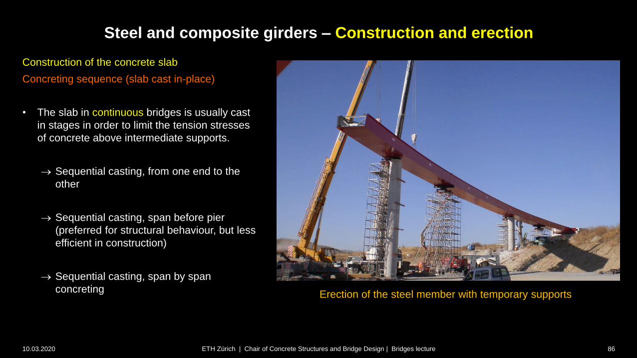
Steel and composite girders – Construction and erection
10.03.2020 86ETH Zürich | Chair of Concrete Structures and Bridge Design | Bridges lecture
Construction of the concrete slab
Concreting sequence (slab cast in-place)
• The slab in continuous bridges is usually cast
in stages in order to limit the tension stresses
of concrete above intermediate supports.
Sequential casting, from one end to the
other
Sequential casting, span before pier
(preferred for structural behaviour, but less
efficient in construction)
Sequential casting, span by span
concretingErection of the steel member with temporary supports

10.03.2020 87ETH Zürich | Chair of Concrete Structures and Bridge Design | Bridges lecture
Steel girder erection
Lifting with cranes
Steel and composite girders – Construction and erection

10.03.2020 88ETH Zürich | Chair of Concrete Structures and Bridge Design | Bridges lecture
Steel girder erection
Lifting with cranes (floating)
Steel and composite girders – Construction and erection
10.03.2020 89ETH Zürich | Chair of Concrete Structures and Bridge Design | Bridges lecture
Steel and composite girders – Construction and erection

10.03.2020 90ETH Zürich | Chair of Concrete Structures and Bridge Design | Bridges lecture
Steel girder erection
Free / balanced cantilevering (lifting frames)
Steel and composite girders – Construction and erection
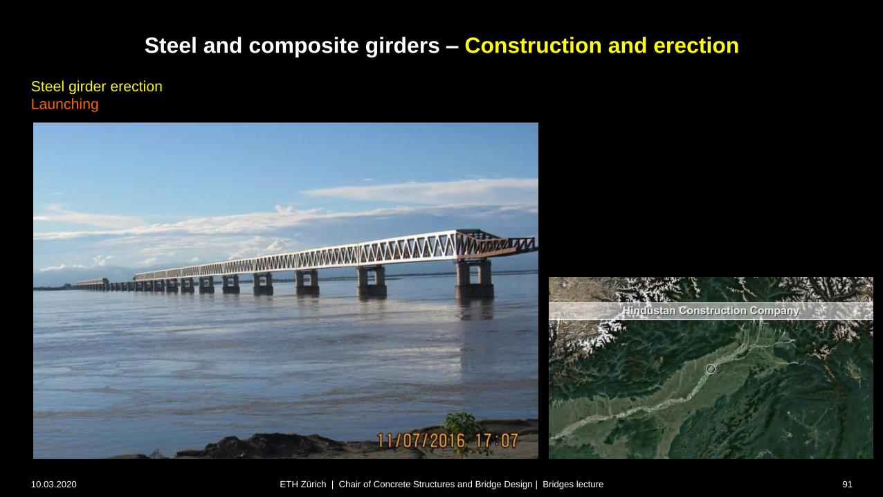
10.03.2020 91ETH Zürich | Chair of Concrete Structures and Bridge Design | Bridges lecture
Steel girder erection
Launching
Steel and composite girders – Construction and erection

10.03.2020 92ETH Zürich | Chair of Concrete Structures and Bridge Design | Bridges lecture
Steel / composite girder erection
Transverse launching (shifting)
• Example: Replacement of Quaibrücke Zürich, 1984
• New bridge: Steel-concrete composite, l=121 m, spans
22.6+24.8+26.5+24.8+22.6 m, width 30.5 m
• Appearance had to mimic old bridge (Volksinitiative), but
only 4 instead of 8 girders, ca. 50% steel weight)
Steel and composite girders – Construction and erection
New bridge under construction (downstream of old bridge)

10.03.2020 93ETH Zürich | Chair of Concrete Structures and Bridge Design | Bridges lecture
Steel / composite girder erection
Transverse launching (shifting)
• Old and new bridges connected for launching,
total weight launched 7’800 t
• Bridge closed to traffic:
Fri 16.3.1984, 21:00 to Mon 19.3.1984, 06:00
• Launching: Sat 17.3.1984, 00:00-15:15 h
(net 14 h launching time)
Steel and composite girders – Construction and erection
temporary substructure:
old bridge after launching
temporary substructure:
new bridge before launching
existing piers
(strengthened, but maintained)
launching direction
new bridge: 30.50 mold bridge: 28.50 m
weight 4070 tweight 3720 t

10.03.2020 94ETH Zürich | Chair of Concrete Structures and Bridge Design | Bridges lecture
Steel / composite girder erection
Transverse launching (shifting)
Steel and composite girders – Construction and erection
New bridge and launching tracks (almost) ready for launchingNew bridge and temporary substructure in lake under construction

10.03.2020 95ETH Zürich | Chair of Concrete Structures and Bridge Design | Bridges lecture
Steel / composite girder erection
Transverse launching (shifting)
Steel and composite girders – Construction and erection
Demolishment of old bridgeTwo bridges travelling towards the lake