supervised wireless security console
TRANSCRIPT
Black 0001
Black0001
SUPERVISED WIRELESSSECURITY CONSOLE
Installation & Programming Instructions
�
(760) 438-7000 • FAX (760) 438-7043USA & Canada (800) 421-1587 & (800) 392-0123
Toll Free FAX (800) 468-1340www.linearcorp.com

Black 0002
Black0002
INTRODUCTION
CONGRATULATIONS for selecting Linear’s DVS-1200Security System. The DVS-1200 Console incorporatesmany advanced and sophisticated features. The systemcan be expanded and customized to fit the installation’sspecific needs.The DVS-1200 Console and its accessories are designedand manufactured by the oldest wireless security companyin North America. You can look ahead to many years ofreliable service with this Console and its accessories.Many insurance companies offer discounts on homeownersand renters policies when a security system is installed.Discount credits vary with different companies andgenerally increase in savings with an increase in the levelof protection. Inform the user to ask their insurance agentabout savings available.The DVS-1200 Console is UL Listed. For a UL smoke alarmsystem, there must be at least one smoke detectorprogrammed into the Console to meet National FireProtection Association (NFPA) Rule 72 Chapter 2 and UL217 requirements. Many insurance companies require youto meet these requirements to qualify for a discount. Onlyuse the Model DXS-72 smoke detector with this Consolefor a UL smoke alarm system.NOTE: Some cities and municipalities may require analarm system permit. Check with your local authoritiesbefore installing this system.In this manual, the bullets preceding the text help to definethe step. For example:
� This symbol indicates a feature.This symbol indicates an action to performand provides a box to check when the actionis completed.
� This symbol is for lit indications or systemsounds.
� This symbol is for important notes.
UL Listed as a Single Station SmokeDetector Accessory, also suitable as a
Household Burglar-Alarm SystemControl Unit.
UL Category CCN UTGT & NBSX.

Black 0003
Black0003
TABLE OF CONTENTS1. THE DVS-1200 SECURITY SYSTEM . . . . . . . . . . . . . . . . . . . . . . . . . . 2
CONSOLE . . . . . . . . . . . . . . . . . . . . . . . . . . . . . . . . . . . . . . . 2DOOR/WINDOW SENSORS . . . . . . . . . . . . . . . . . . . . . . . . . . . . . 3WIRELESS KEYPAD . . . . . . . . . . . . . . . . . . . . . . . . . . . . . . . . . 3SMOKE DETECTORS . . . . . . . . . . . . . . . . . . . . . . . . . . . . . . . . . 3REMOTE CONTROLS . . . . . . . . . . . . . . . . . . . . . . . . . . . . . . . . . 3PANIC BUTTONS . . . . . . . . . . . . . . . . . . . . . . . . . . . . . . . . . . . 3BILL TRAP . . . . . . . . . . . . . . . . . . . . . . . . . . . . . . . . . . . . . . . 3PASSIVE INFRARED MOTION DETECTOR . . . . . . . . . . . . . . . . . . . . . 3GLASS BREAK DETECTOR . . . . . . . . . . . . . . . . . . . . . . . . . . . . . 3
2. SECURITY SYSTEM FLOOR PLAN . . . . . . . . . . . . . . . . . . . . . . . . . . 4EXAMPLE SYSTEM . . . . . . . . . . . . . . . . . . . . . . . . . . . . . . . . . . 4DESIGN THE INSTALLATION . . . . . . . . . . . . . . . . . . . . . . . . . . . . . 4
3. TYPICAL SYSTEM SENSORS . . . . . . . . . . . . . . . . . . . . . . . . . . . . . 5DOOR/WINDOW SENSOR . . . . . . . . . . . . . . . . . . . . . . . . . . . . . . 5WIRELESS KEYPAD . . . . . . . . . . . . . . . . . . . . . . . . . . . . . . . . . 5
4. CONSOLE FEATURES . . . . . . . . . . . . . . . . . . . . . . . . . . . . . . . . . 6
5. CONSOLE INSTALLATION . . . . . . . . . . . . . . . . . . . . . . . . . . . . . . . 8CONSOLE LOCATION . . . . . . . . . . . . . . . . . . . . . . . . . . . . . . . . 8CASE LOCKING SCREW . . . . . . . . . . . . . . . . . . . . . . . . . . . . . . . 8WALL MOUNTING . . . . . . . . . . . . . . . . . . . . . . . . . . . . . . . . . . . 8EXTERNAL CONSOLE SPEAKER CONNECTION (OPTIONAL) . . . . . . . . . . . 9EXTERNAL ALARM SIREN CONNECTION (OPTIONAL) . . . . . . . . . . . . . . 9TELEPHONE LINE CONNECTION (OPTIONAL) . . . . . . . . . . . . . . . . . . 10AUTOMATION OUTPUT CONNECTION (OPTIONAL) . . . . . . . . . . . . . . . 10CONSOLE POWER CONNECTION . . . . . . . . . . . . . . . . . . . . . . . . . 11BACKUP BATTERY INSTALLATION (OPTIONAL) . . . . . . . . . . . . . . . . . 11
6. BASIC CONSOLE PROGRAMMING . . . . . . . . . . . . . . . . . . . . . . . . . 12CREATE THE MASTER USER CODE . . . . . . . . . . . . . . . . . . . . . . . 12PROGRAM THE SENSORS INTO THE CONSOLE’S MEMORY . . . . . . . . . . 12PROGRAMMING DIFFERENT SENSOR TYPES . . . . . . . . . . . . . . . . . . 13
7. BASIC SENSOR INSTALLATION . . . . . . . . . . . . . . . . . . . . . . . . . . 14DXS-10 WIRELESS KEYPAD . . . . . . . . . . . . . . . . . . . . . . . . . . . . 14DXS-31 DOOR/WINDOW SENSORS . . . . . . . . . . . . . . . . . . . . . . . . 15TEST SENSORS . . . . . . . . . . . . . . . . . . . . . . . . . . . . . . . . . . . 15
8. CUSTOMIZING THE CONSOLE . . . . . . . . . . . . . . . . . . . . . . . . . . . 16LABELING THE SENSORS . . . . . . . . . . . . . . . . . . . . . . . . . . . . . 16
9. CONSOLE OPERATING MODES . . . . . . . . . . . . . . . . . . . . . . . . . . . 17OFF MODE . . . . . . . . . . . . . . . . . . . . . . . . . . . . . . . . . . . . . 17CHIME MODE . . . . . . . . . . . . . . . . . . . . . . . . . . . . . . . . . . . . 17HOME MODE . . . . . . . . . . . . . . . . . . . . . . . . . . . . . . . . . . . . 18SECURE EXIT . . . . . . . . . . . . . . . . . . . . . . . . . . . . . . . . . . . . 18HOME INSTANT MODE . . . . . . . . . . . . . . . . . . . . . . . . . . . . . . . 18MANUAL BYPASSING OF SENSORS . . . . . . . . . . . . . . . . . . . . . . . 18AWAY MODE . . . . . . . . . . . . . . . . . . . . . . . . . . . . . . . . . . . . 19MANUAL BYPASSING OF SENSORS . . . . . . . . . . . . . . . . . . . . . . . 19TEST MODE . . . . . . . . . . . . . . . . . . . . . . . . . . . . . . . . . . . . . 20
10. SYSTEM TROUBLE INDICATIONS . . . . . . . . . . . . . . . . . . . . . . . . . . 21CONSOLE LOW BATTERY . . . . . . . . . . . . . . . . . . . . . . . . . . . . . 21SENSOR LOW BATTERIES . . . . . . . . . . . . . . . . . . . . . . . . . . . . . 21SENSOR RADIO TROUBLE . . . . . . . . . . . . . . . . . . . . . . . . . . . . . 21
11. CUSTOMIZING THE SYSTEM . . . . . . . . . . . . . . . . . . . . . . . . . . . . 22ADDING SENSORS TO THE SYSTEM . . . . . . . . . . . . . . . . . . . . . . . 22REMOVING SENSORS FROM THE SYSTEM . . . . . . . . . . . . . . . . . . . 22MAKING A SENSOR A 24-HOUR DOOR CHIME . . . . . . . . . . . . . . . . . . 23MAKING A SENSOR INTERIOR . . . . . . . . . . . . . . . . . . . . . . . . . . 23MAKING A SENSOR ACTIVATE A DIFFERENT ZONE . . . . . . . . . . . . . . 24
12. ADVANCED PROGRAMMING . . . . . . . . . . . . . . . . . . . . . . . . . . . . . 25SETUP MODE . . . . . . . . . . . . . . . . . . . . . . . . . . . . . . . . . . . . 25
CHANGING A SENSORS SUPERVISION . . . . . . . . . . . . . . . . . . 26CHANGING A SENSORS RESTORE REQUIREMENTS . . . . . . . . . . . 26ENTRY DELAY TIME . . . . . . . . . . . . . . . . . . . . . . . . . . . . . 26EXIT DELAY TIME . . . . . . . . . . . . . . . . . . . . . . . . . . . . . . . 26BURGLARY SIREN TIME . . . . . . . . . . . . . . . . . . . . . . . . . . . 26EMERGENCY SIREN TIME . . . . . . . . . . . . . . . . . . . . . . . . . . 26FIRE SIREN TIME . . . . . . . . . . . . . . . . . . . . . . . . . . . . . . . 27AUTOMATION OUTPUT TIME . . . . . . . . . . . . . . . . . . . . . . . . 27REMOTE CONTROL ARMING LEVEL . . . . . . . . . . . . . . . . . . . . 27REMOTE CONTROL DISARMING LEVEL . . . . . . . . . . . . . . . . . . 27ENTRY DELAY BEEPS . . . . . . . . . . . . . . . . . . . . . . . . . . . . 27EXIT DELAY BEEPS . . . . . . . . . . . . . . . . . . . . . . . . . . . . . . 27SILENT BURGLARY ALARMS . . . . . . . . . . . . . . . . . . . . . . . . 28SILENT EMERGENCY ALARMS . . . . . . . . . . . . . . . . . . . . . . . 28DISABLING QUICK ARMING . . . . . . . . . . . . . . . . . . . . . . . . . 28AUTOMATIC RESTORAL OF BYPASSED SENSORS . . . . . . . . . . . . 28AUTOMATIC BYPASSING OF OPEN SENSORS . . . . . . . . . . . . . . . 28AUTOMATION OUTPUT MODE DURING ALARM . . . . . . . . . . . . . . 29AUTOMATION ACTIVATION TONE . . . . . . . . . . . . . . . . . . . . . . 29REMOTE CONTROL ARM/DISARM CHIRP . . . . . . . . . . . . . . . . . 29AUTOMATION OUTPUT FLASHES DURING AND AFTER ALARM . . . . . 29AUTOMATION OUTPUT ON DURING ALARM . . . . . . . . . . . . . . . . 29AUTOMATION OUTPUT WHILE ARMED . . . . . . . . . . . . . . . . . . . 30AUTOMATION OUTPUT DURING EXIT/ENTRY DELAYS . . . . . . . . . . 30AUTOMATION OUTPUT POLARITY . . . . . . . . . . . . . . . . . . . . . 30REMOTE ACCESS PASSWORD . . . . . . . . . . . . . . . . . . . . . . . 30DURESS CODE . . . . . . . . . . . . . . . . . . . . . . . . . . . . . . . . 30MASTER USER CODE . . . . . . . . . . . . . . . . . . . . . . . . . . . . 30ADDITIONAL USER CODES . . . . . . . . . . . . . . . . . . . . . . . . . 31REMOVING USER CODES . . . . . . . . . . . . . . . . . . . . . . . . . . 31CONSOLE MASTER RESET . . . . . . . . . . . . . . . . . . . . . . . . . 31
13. COMMUNICATOR PROGRAMMING . . . . . . . . . . . . . . . . . . . . . . . . . 32SETUP MODE . . . . . . . . . . . . . . . . . . . . . . . . . . . . . . . . . . . . 32GENERAL COMMUNICATOR OPTIONS . . . . . . . . . . . . . . . . . . . . . . 33
COMMUNICATOR ENABLE . . . . . . . . . . . . . . . . . . . . . . . . . . 332-WAY AUDIO . . . . . . . . . . . . . . . . . . . . . . . . . . . . . . . . . 33VOICE RESPONSE . . . . . . . . . . . . . . . . . . . . . . . . . . . . . . 33REMOTE LOCKOUT . . . . . . . . . . . . . . . . . . . . . . . . . . . . . . 33CALL LIMITER . . . . . . . . . . . . . . . . . . . . . . . . . . . . . . . . . 34DIALING DELAY . . . . . . . . . . . . . . . . . . . . . . . . . . . . . . . . 34DIALING METHOD . . . . . . . . . . . . . . . . . . . . . . . . . . . . . . 34
COMMUNICATOR REPORTING OPTIONS . . . . . . . . . . . . . . . . . . . . . 35REPORTING FORMAT . . . . . . . . . . . . . . . . . . . . . . . . . . . . 35CALL ROUTING . . . . . . . . . . . . . . . . . . . . . . . . . . . . . . . . 35ACCOUNT NUMBER . . . . . . . . . . . . . . . . . . . . . . . . . . . . . 36PRIMARY TELEPHONE NUMBER . . . . . . . . . . . . . . . . . . . . . . 36SECONDARY TELEPHONE NUMBER . . . . . . . . . . . . . . . . . . . . 36SUPERVISORY/PAGER TELEPHONE NUMBER . . . . . . . . . . . . . . 36REPORT CONSOLE TROUBLE . . . . . . . . . . . . . . . . . . . . . . . . 37REPORT FORCE ARMING . . . . . . . . . . . . . . . . . . . . . . . . . . 37OPENING AND CLOSING REPORTS . . . . . . . . . . . . . . . . . . . . . 37POINT ID REPORTING . . . . . . . . . . . . . . . . . . . . . . . . . . . . 37
COMMUNICATOR REPORTING CODES . . . . . . . . . . . . . . . . . . . . . . 38GENERAL REPORTING CODES . . . . . . . . . . . . . . . . . . . . . . . 38SYSTEM REPORTING CODES . . . . . . . . . . . . . . . . . . . . . . . . 38FORCE ARMING REPORTING CODE . . . . . . . . . . . . . . . . . . . . 39DURESS REPORTING CODE . . . . . . . . . . . . . . . . . . . . . . . . . 39
4 BY 2 FORMAT POINT ID REPORTING CODES . . . . . . . . . . . . . . . . . 404 BY 2 FORMAT POINT ID ALARM REPORT CODES . . . . . . . . . . . . 404 BY 2 FORMAT POINT ID TROUBLE REPORT CODES . . . . . . . . . . 40
IMPORTANT INFORMATION . . . . . . . . . . . . . . . . . . . . . . . . . . . . . . . . 42LINEAR LIMITED WARRANTY . . . . . . . . . . . . . . . . . . . . . . . . . . . . 42WIRELESS PRODUCT NOTICE . . . . . . . . . . . . . . . . . . . . . . . . . . . 42FCC NOTICE . . . . . . . . . . . . . . . . . . . . . . . . . . . . . . . . . . . . . 42FCC TELEPHONE RULES AND REGULATIONS . . . . . . . . . . . . . . . . . . 42FIRE EVACUATION PLANNING . . . . . . . . . . . . . . . . . . . . . . . . . . . 42INDUSTRY CANADA NOTICES . . . . . . . . . . . . . . . . . . . . . . . . . . . 42
1
Black 0004
Black0004
1. THE DVS-1200 SECURITY SYSTEM
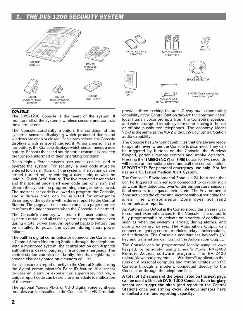
CONSOLEThe DVS-1200 Console is the heart of the system. Itmonitors all of the system’s wireless sensors and controlsthe alarm sirens.The Console constantly monitors the condition of thesystem’s sensors, displaying which protected doors andwindows are open or closed. If an alarm occurs, the Consoledisplays which sensor(s) caused it. When a sensor has alow battery, the Console displays which sensor needs a newbattery. Sensors that send hourly status transmissions keepthe Console informed of their operating condition.Up to eight different custom user codes can be used tooperate the system. For security, a user code must beentered to disarm (turn off) the system. The system can bearmed (turned on) by entering a user code, or with theunique “Quick Arm” feature. The five restricted user codesand the special page alert user code can only arm anddisarm the system, no programming changes are allowed.The master user code is allowed to program the Console,and a duress code can be selected for emergencydisarming of the system with a duress report to the CentralStation. The page alert user code can dial a pager numberto inform the pager wearer when the Console is disarmed.The Console’s memory will retain the user codes, thesystem’s mode, and all of the system’s programming, evenduring a total power loss. An optional backup battery canbe installed to power the system during short powerfailures.The built-in digital communicator connects the Console toa Central Alarm Monitoring Station through the telephone.With a monitored system, the central station can dispatchauthorities in case of burglary, fire or other emergency. Thecentral station can also call family, friends, neighbors, oranyone else designated on a custom call list.Each sensor can report directly to the Central Station usingthe digital communicator’s Point ID feature. If a sensortriggers an alarm or experiences supervisory trouble, aunique report code can be sent for immediate identificationof the event.The optional Models VB-2 or VB-3 digital voice synthesismodules can be installed in the Console. The VB-2 module
provides three exciting features: 2-way audio monitoringcapability at the Central Station through the communicator,local human voice prompts from the Console’s speaker,and voice prompted remote system control using in-houseor off-site pushbutton telephones. The economy ModelVB-3 is the same as the VB-2 without 2-way Central Stationaudio capability.The Console has 24-hour capabilities that are always readyto operate, even when the Console is disarmed. They canbe triggered by buttons on the Console, the WirelessKeypad, portable remote controls and smoke detectors.Pressing the [EMERGENCY] or [FIRE] button for two secondswill cause an immediate siren and call the central station.IMPORTANT: For personal emergency use only. Not foruse as a UL Listed Medical Alert System.The Console’s Environmental Zone is a 24-hour zone thatcan be triggered with sensors connected to devices suchas water flow detectors, over/under temperature sensors,flood sensors, toxic gas detectors, etc. The EnvironmentalZone activates the chime annunciator without sounding thesiren. The Environmental Zone does not sendcommunicator reports.An Automation Output in the Console provides an easy wayto connect external devices to the Console. The output isfully programmable to activate on a variety of conditions,such as when the system is armed, during alarms, andduring exit/entry delays. The Automation Output canconnect to lighting control modules, relays, noisemakers,and indicators. The Console’s and wireless keypad’s (A)key and transmitters can control the Automation Output.The Console can be programmed locally using its ownkeypad, or remotely, using Linear’s Model RA-2400Remote Access software program. The RA-2400upload/download program is a Windows™ application thatruns on a personal computer and communicates with theConsole through a modem, connected directly to theConsole, or through the telephone line.A total of 12 sensors of the types listed on the next pagecan be used with each DVS-1200 Console. Each burglarysensor can trigger the siren (and report to the CentralStation) once per arming cycle. 24-hour sensors haveunlimited alarm and reporting capacity.
DXS-91 GLASSBREAK DETECTOR †
DXS-72SMOKE DETECTOR
DVS-1200CONSOLE DXS-10
WIRELESSKEYPAD
DXS-31DOOR/WINDOW
SENSOR
DXS-54PIR
DXT-41 & DXT-42REMOTES
DXT-61REMOTE
DXS-81BILL TRAP †
DXT-21 & DXT-23REMOTES †
DXS-32DOOR/WINDOW
SENSOR
† NOTE: These accessoriesare not listed by UL.
2

Black 0005
Black0005
DOOR/WINDOW SENSORSThe DXS-31 and DXS-32 sensors monitor doors and windows.They send radio signals to the Console. One type of signal issent when the door or window is opened, and a different type ofsignal is sent when the door or window is closed. If the Consoleis armed, a sensor can trigger the Console’s burglary siren whenits door or window is opened. Both models are supervised, andsend hourly status reports and monitors its battery condition.
WIRELESS KEYPADThe DXS-10 wireless keypad is used to control the Consoleremotely. It can be placed in a convenient spot so the userdoesn’t have to go to the Console to control the system. Thewireless keypad can also trigger the emergency or fire siren andactuate the Automation Output. Pressing the [∗] key will causethe Console to sound beeps corresponding to the currentoperating mode. The DXS-10 is supervised, it sends hourlystatus reports and monitors its battery condition. IMPORTANT:For personal emergency use only. Not for use as a UL ListedMedical Alert System.
SMOKE DETECTORSThe DXS-72 is a high quality smoke detector with a built-inradio transmitter. As soon as smoke is detected, the unit willsound its local noisemaker. Then, 20 seconds after the localnoisemaker sounds, the transmitter sends an alarm signal tothe Console. The alarm signal will be repeated every 20seconds as long as smoke is still present. A restoral signal willbe sent when the smoke detection chamber clears. The DXS-72is supervised, it sends hourly status reports and monitorsbattery condition.� NOTE: A Model DXS-72 Smoke Detector is required to
create a UL Listed smoke alarm system. See Page 22 fordetails on adding a smoke detector sensor to the system.
REMOTE CONTROLSThe DXT-41, DXT-61 single-button and DXT-23, DXT-42multi-button remote controls can be used to remotely arm anddisarm the Console. The DXT-42’s left button will arm the andthe right button will disarm the Console. Pressing both buttonssimultaneously will trigger the emergency siren. Alternately, theConsole can be programmed to respond to the DXT-42 byarming and disarming with the left button, and activating theautomation output with the right button.These transmitters canalso be programmed to activate various other Console zones.These transmitters are not supervised.
PANIC BUTTONSThe DXT-21 and DXT-23 transmitters can be used as portable“panic buttons”. Pressing the front or top button on the DXT-21at any time will trigger the emergency siren. Pressing bothfront buttons simultaneously on the DXT-23 at any timewill trigger the emergency siren. Both transmitters can beprogrammed to activate various other Console zones.These transmitters are not supervised.
BILL TRAPThe DXS-81 bill trap can be used with the Console innon-UL small commercial hold-up installations. The unit isconcealed in a cash drawer under a stack of currency, witha single “bait” bill secured in its money clip. During ahold-up, the cashier removes the stack of currency alongwith the “bait” bill. When a “bait” bill is removed, thetransmitter sends a signal to the Console. Four additionalsignals are sent within the first minute after the “bait” bill isremoved. When the “bait” bill is replaced, a restore signalis sent. The DXS-81 is supervised, it can send hourly statusreports (optional) and monitors its battery condition.
PASSIVE INFRARED MOTION DETECTORThe DXS-54 is a passive infrared (PIR) motion detector witha built-in radio transmitter. The PIR detects motion in itsdetection pattern by measuring the infrared emission levelsof objects that it “sees”. If the infrared levels changequickly, as when a person moves across the detectionpattern, the PIR will recognize the change as an intrusionand send an alarm signal to the Console. An alarm will betriggered if the Console is in the Away Mode. The DXS-54is supervised, it sends hourly status reports and monitorsits battery condition.
GLASS BREAK DETECTORThe DXS-91 is a glass break detector with an audio sounddiscriminator and a built-in radio transmitter. The unit“listens” for the sound of breaking glass. When glassbreakage is detected, the unit sends an alarm signal to theConsole. The DXS-91 is supervised, it sends hourly statusreports and monitors its battery condition.
DXS-32
DXS-31
DXS-10
DXS-54
‡ NOTE: These accessories not listed by UL. DXS-91 ‡
DXS-72
DXT-41
DXT-61
DXT-42
DXT-21 ‡ DXT-23 ‡
DXS-81 ‡
3
Black 0006
Black0006
2. SECURITY SYSTEM FLOOR PLAN
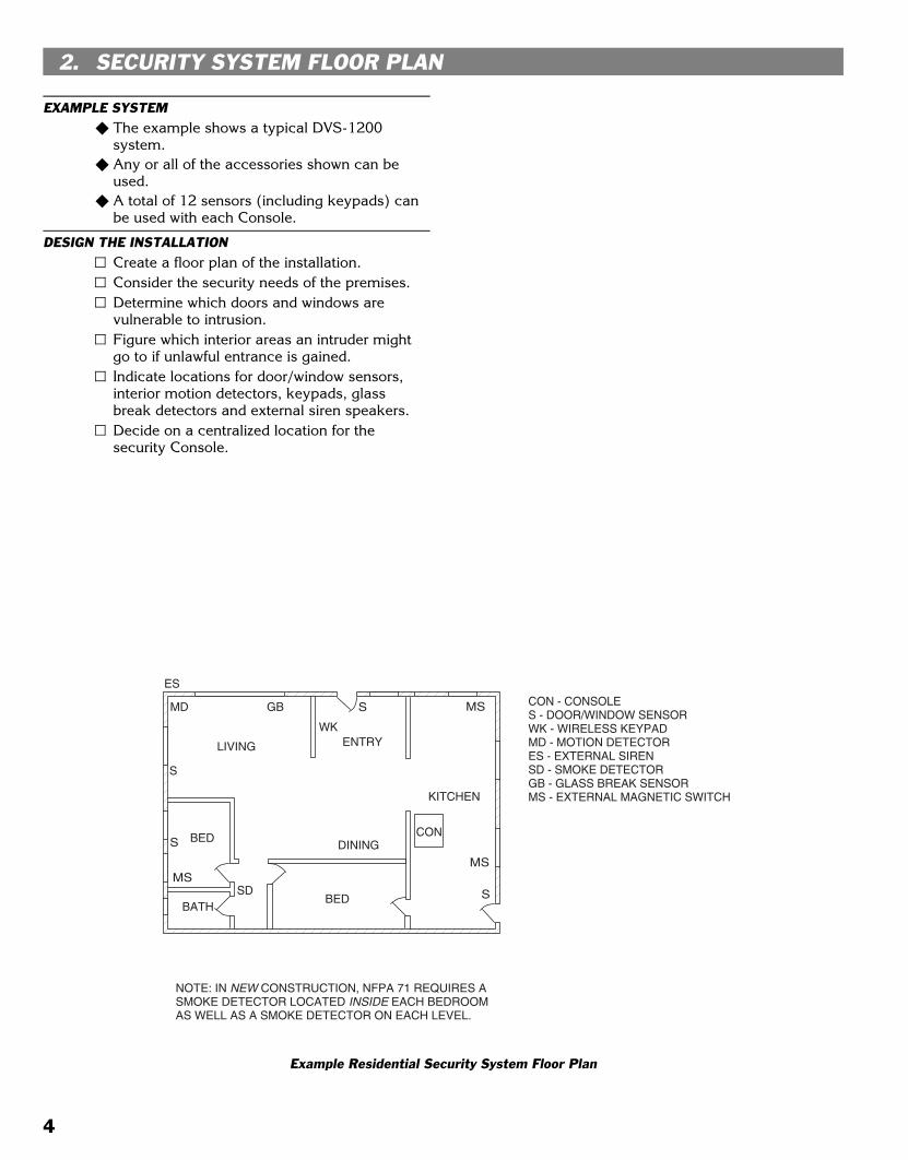
EXAMPLE SYSTEM� The example shows a typical DVS-1200
system.� Any or all of the accessories shown can be
used.� A total of 12 sensors (including keypads) can
be used with each Console.
DESIGN THE INSTALLATIONCreate a floor plan of the installation.Consider the security needs of the premises.Determine which doors and windows arevulnerable to intrusion.Figure which interior areas an intruder mightgo to if unlawful entrance is gained.Indicate locations for door/window sensors,interior motion detectors, keypads, glassbreak detectors and external siren speakers.Decide on a centralized location for thesecurity Console.
CON
MS
ES
WK
S
S
S
MD MS
SMS
CON - CONSOLES - DOOR/WINDOW SENSORWK - WIRELESS KEYPADMD - MOTION DETECTORES - EXTERNAL SIRENSD - SMOKE DETECTORGB - GLASS BREAK SENSORMS - EXTERNAL MAGNETIC SWITCH
LIVING
DINING
KITCHEN
ENTRY
BED
BATH
GB
SDBED
NOTE: IN NEW CONSTRUCTION, NFPA 71 REQUIRES A SMOKE DETECTOR LOCATED INSIDE EACH BEDROOMAS WELL AS A SMOKE DETECTOR ON EACH LEVEL.
Example Residential Security System Floor Plan
4
Black 0007
Black0007
3. TYPICAL SYSTEM SENSORS
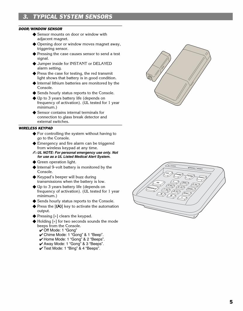
DOOR/WINDOW SENSOR� Sensor mounts on door or window with
adjacent magnet.� Opening door or window moves magnet away,
triggering sensor.� Pressing the case causes sensor to send a test
signal.� Jumper inside for INSTANT or DELAYED
alarm setting.� Press the case for testing, the red transmit
light shows that battery is in good condition.� Internal lithium batteries are monitored by the
Console.� Sends hourly status reports to the Console.� Up to 3 years battery life (depends on
frequency of activation). (UL tested for 1 yearminimum.)
� Sensor contains internal terminals forconnection to glass break detector andexternal switches.
WIRELESS KEYPAD� For controlling the system without having to
go to the Console.� Emergency and fire alarm can be triggered
from wireless keypad at any time.� UL NOTE: For personal emergency use only. Not
for use as a UL Listed Medical Alert System.
� Green operation light.� Internal 9-volt battery is monitored by the
Console.� Keypad’s beeper will buzz during
transmissions when the battery is low.� Up to 3 years battery life (depends on
frequency of activation). (UL tested for 1 yearminimum.)
� Sends hourly status reports to the Console.� Press the [(A)] key to activate the automation
output.� Pressing [∗] clears the keypad.� Holding [∗] for two seconds sounds the mode
beeps from the Console.� Off Mode: 1 “Gong”� Chime Mode: 1 “Gong” & 1 “Beep”.� Home Mode: 1 “Gong” & 2 “Beeps”.� Away Mode: 1 “Gong” & 3 “Beeps”.� Test Mode: 1 “Bing” & 4 “Beeps”.
5
Black 0008
Black0008
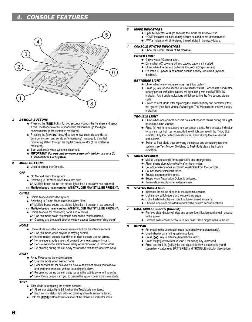
4. CONSOLE FEATURES
1 24-HOUR BUTTONS� Pressing the [FIRE] button for two seconds sounds the fire siren and sends
a “fire” message to a central monitoring station through the digitalcommunicator (if the system is monitored).
� Pressing the [EMERGENCY] button for two seconds sounds theemergency siren and sends an “emergency” message to a centralmonitoring station through the digital communicator (if the system ismonitored).
� Both work even when system is disarmed.� IMPORTANT: For personal emergency use only. Not for use as a UL
Listed Medical Alert System.
2 MODE BUTTONS� Used to control the Console.
OFF� Off Mode disarms the system.� Switching to Off Mode stops the alarm siren.
� Multiple beeps sound and status lights flash if an alarm has occurred.� Multiple beeps mean caution. AN INTRUDER MAY STILL BE PRESENT.
CHIME� Chime Mode disarms the system.� Switching to Chime Mode stops the alarm siren.
� Multiple beeps sound and status lights flash if an alarm has occurred.� Multiple beeps mean caution. AN INTRUDER MAY STILL BE PRESENT.� Chime Mode is for monitoring doors and windows.
� Use this mode as an “automatic door chime” when at home.� Opening any protected door or window causes Console to “ding-dong”.
HOME� Home Mode arms the perimeter sensors, but not the interior sensors.
� Use this mode when anyone is staying behind.� Interior motion detectors and interior door sensors are not armed.� Home secure mode makes all delayed perimeter sensors instant.� Secure exit mode starts an exit delay while remaining in Home Mode.� Re-entering during the exit delay restarts the exit delay (one time only).
AWAY� Away Mode arms the entire system.
� Use this mode when leaving home.� Door sensors set for delayed will have a delay that allows you to leave
and enter the premises without sounding the alarm.� Re-entering during the exit delay restarts the exit delay (one time only).� Entry Delay beeps warn you to disarm the system before the siren starts.
TEST� Test Mode is for testing the system sensors.
� All sensor status lights blink when the Test Mode is entered.� Each sensor status light will stop blinking when its sensor is tested.
� Hold the [TEST] button down to test all of the Console’s indicator lights.
3 MODE INDICATORS� Specific indicator will light showing the mode the Console is in.� HOME indicator will blink during secure exit and home instant modes.� AWAY indicator will blink during the exit delay in the Away Mode.
4 CONSOLE STATUS INDICATORS� Show the current status of the Console.
POWER LIGHT� Glows when AC power is on.� Dims when AC power is off and backup battery is installed.� Blinks when the backup battery is low, recharging or missing.� Off when AC power is off and no backup battery is installed (system
disabled).
BATTERIES LIGHT� Blinks when one or more sensors has a low battery.� Press [∗] key for one second to view sensor status. Sensor status indicator
for any sensor with a low battery will light along with the BATTERIESindicator. Any trouble indications will follow during the five second statuscycle.
� Switch to Test Mode after replacing the sensor battery and completely testthe system (see Test Mode). Switching to Test Mode clears the low batteryindication.
TROUBLE LIGHT� Blinks when one or more sensors have not reported status during the eight
hour status time window. � Press [∗] key for one second to view sensor status. Sensor status indicator
for any sensor that has not reported in will light along with the TROUBLEindicator. Any low battery indications will follow during the five secondstatus cycle.
� Switch to Test Mode after servicing the sensor and completely test thesystem (see Test Mode). Switching to Test Mode clears the troubleindication.
5 SIREN SPEAKER� Makes unique sounds for burglary, fire and emergencies.� Alarm sirens stop automatically after five minutes.� Sounds advisory tones to confirm keystrokes from the Console.� Sounds mode selections tones.� Sounds alarm memory tones.� Beeps when Automation Output is activated.� Terminals available for an external siren.
6 STATUS INDICATORS� Indicates the status of each of the system’s sensors.� Lights show which doors and windows are open.� Lights flash to display sensors that have caused an alarm.� Stick-on labels are provided to identify the custom sensor locations.
7 CASE ACCESS SCREW (HIDDEN)� Remove clear display window and sensor identification card to gain access
to the screw.� Remove case access screw to unlock case. Case hinges open to the left.
8 KEYPAD� For entering the user’s user code (numerically or alphabetically).� Used when programming system options.� Press [(A)] key to activate Automation Output.� Press the [∗] key to clear keypad if the wrong key is pressed.� Press and hold the [∗] key for one second to view sensor battery and
supervisory status (see BATTERIES and TROUBLE indicator description).
1
2
3
45
6
7
8
6

Black 0009
Black0009
10 AUXILIARY FUSE� Type 2AG, 1-amp fuse.� Protects the external relay output when used with wet contacts (12 VDC
switched out).� Fuse will blow when load exceeds 1 amp.� WARNING: For continued protection against the risk of fire, replace
only with the same type and rating of fuse.
11 MAIN TERMINAL BLOCK� Terminals for connection to the plug-in AC transformer.� Terminals for connection to an external siren speaker.� Automation Output to connect to an automation controller.� External relay output for “wet” contacts (switched 12 volts) or “dry” contacts
(normally open 1 amp @ 24 volts maximum).
12 BATTERY FUSE� Type 2AG, 3-amp fuse for the backup battery.� If the POWER light is flashing and the optional backup battery is installed
and charged, check this fuse.� WARNING: For continued protection against the risk of fire, replace
only with the same type and rating of fuse.
13 TELEPHONE TERMINAL BLOCK� Provides telephone connections for the digital communicator. � Provides seized ring and tip connections for local telephone instruments.
Communicator will disconnect local telephones while on-line.
14 INTERNAL SPEAKER CONNECTOR� Connects the internal speaker to the Console circuit board.� 2-pin connector, non-polarized.
15 ANTENNA TERMINALS� Antenna and ground terminals for receiving signals from the system’s
sensors.� Pre-wired to the Console’s internal wire dipole antenna.� Alternately connects to the Model LA-P local whip and remote antenna kit.
16 OPTIONAL BACKUP BATTERY� Space for 12-volt, 1.2 amp/hour backup battery. (Highly recommended.)� Backup battery is automatically charged and monitored by the Console.� Backup battery can power the Console for up to 6 hours.� UL NOTE: Normal estimated battery life should be 3 to 4 years.
17 WIRING ACCESS HOLE� Provides access to recessed wiring trough in base of Console.� Route cables for power, telephone, external speaker, etc. through this hole.� Loop for zip-tie strain relief provided next to hole.
18 WALL-MOUNT SLOTS� Used when mounting Console recessed in the wall.� Two mounting brackets (supplied) slide through slots and are retained by
screws, clamping the unit to the wall.
19 RADIO TEST POINTS� Used to monitor the Console’s radio receiver during troubleshooting.� Provides connection for an audio amplifier to listen to the receiver’s output.� Helpful to determine sources of radio interference.
20 MICROPHONE (WITH MODEL VB-2 INSTALLED ONLY)� High sensitivity microphone.� Detects room audio when communicator is reporting to the Central Station
in 2-way audio mode (Model VB-2 must be installed).
21 ANNUNCIATOR VOLUME CONTROL� Varies the volume of the advisory tones that come from the speaker.� Does not affect internal or external sirens (they are always full volume).
22 DIGITAL VOICE SYNTHESIS MODULE (OPTIONAL)� Two voice synthesis modules are available, the Model VB-2 and VB-3.� Both modules allow remote command of the Console using a standard
pushbutton telephone, on or off site.� Both modules provide optional human voice prompts from the Console’s
speaker.� The Model VB-2 gives the Console’s digital communicator listen-only,
manual 2-way and full duplex 2-way audio capability with the CentralStation.
� Units programmed for two-way duplex can be controlled manually bypressing the “1" or ”3" key. The central Station can now return the unit totwo-way duplex by pressing the “8" key.
10
11 12
13 14
2221
20
1516
17
1819
7
Black 0010
Black0010
5. CONSOLE INSTALLATION
CONSOLE LOCATION� NOTE: Sensor signals must be able to reach the
Console.� Try to centrally locate the Console.� Keep Console away from large metal
appliances.� Maximum recommended sensor range is
400 feet (system tested at 1000 feet).� NOTE: If you don’t use the Wireless Keypad, the
Console should be easily accessible to the usualentrance.
� When the Console is set in the Away Mode,the user has 30 seconds to switch to OffMode before the burglary siren sounds.
� NOTE: Make sure the Console is in a place wherethe alarm can be heard during the night hours.
� Optional remote external sirens (up to 150feet from the Console) can be used to makealarms louder and remote their location.
Locate the Console near a 115 VAC outletthat’s not controlled by a light switch.Locate the Console near a telephone outlet (ifusing the digital communicator).
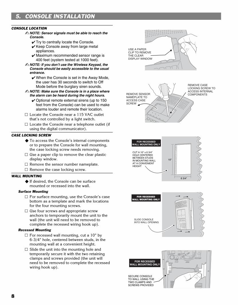
CASE LOCKING SCREW� To access the Console’s internal components
or to prepare the Console for wall mounting,the case locking screw needs removing.Use a paper clip to remove the clear plasticdisplay window.Remove the sensor number nameplate.Remove the case locking screw.
WALL MOUNTING� If desired, the Console can be surface
mounted or recessed into the wall.Surface Mounting
For surface mounting, use the Console’s casebottom as a template and mark the locationsfor the four mounting screws.Use four screws and appropriate screwanchors to temporarily mount the unit to thewall (the unit will need to be removed tocomplete the recessed wiring hook up).
Recessed MountingFor recessed wall mounting, cut a 10" by6-3/4" hole, centered between studs, in themounting wall at a convenient height.Slide the unit into the mounting hole andtemporarily secure it with the two retainingclamps and screws provided (the unit willneed to be removed to complete the recessedwiring hook up).
6 3/4"
10"
CUT A 10" x 6 3/4"HOLE CENTEREDBETWEEN STUDSIN MOUNTING WALLAT A CONVENIENTHEIGHT
FOR RECESSEDWALL MOUNTING ONLY
SLIDE CONSOLEINTO WALL OPENING
FOR RECESSEDWALL MOUNTING ONLY
SECURE CONSOLE TO WALL USING THE TWO CLAMPS AND SCREWS PROVIDED
FOR RECESSEDWALL MOUNTING ONLY
USE A PAPER CLIP TO REMOVETHE CLEAR DISPLAY WINDOW
REMOVE SENSOR NAMEPLATE TO ACCESS CASE SCREW
REMOVE CASE LOCKING SCREW TO ACCESS INTERNAL COMPONENTS
8

Black 0011
Black0011
EXTERNAL CONSOLE SPEAKER CONNECTION (OPTIONAL)� An external console speaker sounds system
tones and alerts occupants with a loud sirenduring alarm.
� With the VB-2 module installed, the CentralStation can talk to the occupants through theexternal console speaker.
� Use an 8-ohm, 10 watt minimum ratedspeaker. Do not use a horn/siren with abuilt-in siren driver.
� Up to two 8-ohm speakers can be used witheach Console.
� Up to 150 feet of 22 AWG wire can be usedwith each speaker.Mount the external speaker.Route the speaker wires from the externalspeaker to the Console.Open the Console top cover and locate themain terminal block.Route the speaker wires up through the wiringaccess hole.Remove the wire jumper from the EXT. SPKR& (-) terminals.Connect the speaker wires to the EXT. SPKR& (-) terminals.
� NOTE: If connecting two external speakers,connect the second speaker in parallel, to thesame EXT. SPKR & (-) terminals as the firstspeaker.
The system tone volume can be adjusted withthe annunciator volume control.
EXTERNAL ALARM SIREN CONNECTION (OPTIONAL)� An external siren alerts occupants and
neighbors with a loud siren during alarm.� Use a 12 volt, 1 amp maximum rated
weather-resistant horn speaker with a built-insiren driver. Do not use a plain speaker.
� NOTE: Connection of an electromechanical bell ormotor bell is not recommended because of theradio interference generated when the bell isrunning.
� UL NOTE: Not for use in UL installations.
Mount the external siren.Route the wires from the external siren to theConsole.Open the Console top cover and locate themain terminal strip.Route the siren wires up through the wiringaccess hole.Connect the siren wires to the RELAY N.O. &(-) terminals.
� NOTE: By removing the Console’s auxiliary fuse,the relay contacts will become isolated. Use theRELAY N.O. & RELAY DRY terminals to switch anexternally powered load.
EXTERNALCONSOLESPEAKER
ACACEXT. SPKR(-)H/A -H/A +RELAY N.O.RELAY DRY
MAIN TERMINAL BLOCK
EXT. SPKR(S)8 OHM/10 WATT2 SPKRS MAX.
NOTE: REMOVEJUMPER FOR
EXT. SPEAKERSOPTIONAL
VOICE MODULEMODEL: VB-4
MAINTERMINAL
BLOCK
ANNUNCIATORVOLUME
CONTROL
LINEAR SECURITY CONSOLE MODEL DVS-1200
CONNECT SPEAKER LEADSTO EXT. SPKR & (-) TERMINALS
REMOVEJUMPER
EXTERNALCONSOLESPEAKER
8 OHM, 10 WATTMINIMUM
CONNECT SIREN LEADS TO(-) & RELAY N.O. TERMINALS
EXTERNALALARM RELAY12 VDC 1 AMP
MAXIMUM
ACACEXT. SPKR(-)H/A -H/A +RELAY N.O.RELAY DRY
MAIN TERMINAL BLOCK
EXTERNAL SIREN12 VDC 1 AMP
MAXIMUM
OPTIONALVOICE MODULE
MODEL: VB-4
MAINTERMINAL
BLOCK
LINEAR SECURITY CONSOLE MODEL DVS-1200
EXTERNALALARMSIREN
9

Black 0012
Black0012
TELEPHONE LINE CONNECTION (OPTIONAL)� Connect the Console to the telephone line if
the system is monitored, requires 2-wayaudio, or requires telephone remote command.
� Telephone ring & tip terminals are forconnection to the incoming telephone line.
� Seized telephone ring & tip are for connectionto local telephone sets. When thecommunicator activates, all the localtelephone sets will be disconnected to preventan off-hook telephone on the premises fromblocking the communicator call.Install a USOC RJ31-X or RJ38-X jack to thetelephone system near the Console.Route an appropriate modular telephone linecord from the jack to the Console.Route the line cord through the Console’swiring access hole.Connect the incoming telephone line wires tothe Console’s telephone terminal block TIPand RING terminals.Connect the local telephone set wires to theConsole’s telephone terminal block SEIZEDTIP and SEIZED RING terminals.
� When directly connecting (without a telephoneline) to the DVS-1200 with the RA-2400remote access software (Version 1.3 or later),disconnect the incoming telephone line andconnect the modem to the panel’s TIP andRING terminals (with the modem’s red &green phone line wires). Press the[EMERGENCY] key while in Test Mode tocause the panel to connect to the modem.
AUTOMATION OUTPUT CONNECTION (OPTIONAL)� The Console provides a Automation Output to
control lights, devices and appliances.� Automation Output can connect to most
popular home automation devices and othersimple electronic devices (see Figure).Press [(A)] to turn the Automation Output on,press [(A)] again to turn it off.
Programmable Options� There are many programmable options for the
Automation Output.� The Automation Output can be programmed
for a variety of useful functions, such as:flashing during alarm, flashing after an alarm,on while armed, or, on during exit/entrydelays.
� See the “Advanced Programming” section ofthis manual for details on changing thefunction of the Automation Output.
OPTIONALVOICE MODULE
MODEL: VB-4
TELEPHONETERMINAL
BLOCK LINEAR SECURITY CONSOLE MODEL DVS-1200
TELEPHONE TERMINAL BLOCK
RTR1
T1
TO PHONELINE
RINGTIP
TO LOCALPHONES
SEIZED TIPSEIZED RING
SEIZEDRING (R1)
SEIZEDTIP (T1)
LINERING (R)
LINETIP (T)
GRAY
RED
T
R T1
R1
1 32 4 5 6 7 8
TO LOCALTELEPHONESETS
TO TELEPHONENETWORK
8-POSITIONUSOC RJ31-X(OR RJ38-X)
JACK
TRR1 T1 SHORTING BARSHORT REMOVEDON PLUG INSERTION
8-PINMODULAR
PHONE CORD
DVS-1200TELEPHONETERMINAL
BLOCK
GREEN
BROWN
BLUE, ORANGE BLACK, AND YELLOW NOT USED
CONNECT TELEPHONE LINETO THE TELEPHONETERMINAL BLOCK
ACACEXT. SPKR(-)H/A -H/A +RELAY N.O.RELAY DRY
MAIN TERMINAL BLOCK
OPTIONALVOICE MODULE
MODEL: VB-4
MAINTERMINAL
BLOCK
LINEAR SECURITY CONSOLE MODEL DVS-1200
LIGHT EMITTINGDIODE (L.E.D.)
MINUS H/A TERMINAL WILL SWITCHTO GROUND WHEN AUTOMATIONOUTPUT IS ACTIVATED
POSITIVE H/A TERMINAL PROVIDES+12 VOLTS DC AND IS CURRENTLIMITED AT 30 MILLIAMPS MAXIMUM
X-10BURGLAR ALARMINTERFACE(CAN CONTROLHOUSE LIGHTSTHROUGH X-10SYSTEM)
X-10LINEAR RB-90
RELAY MODULEYOURLOAD
POWERSOURCE
LIGHTEMITTINGDIODE(L.E.D.)
EXAMPLE AUTOMATION OUTPUT HOOK-UPS
H/A + H/A - H/A + H/A - H/A + H/A -
10
Black 0013
Black0013
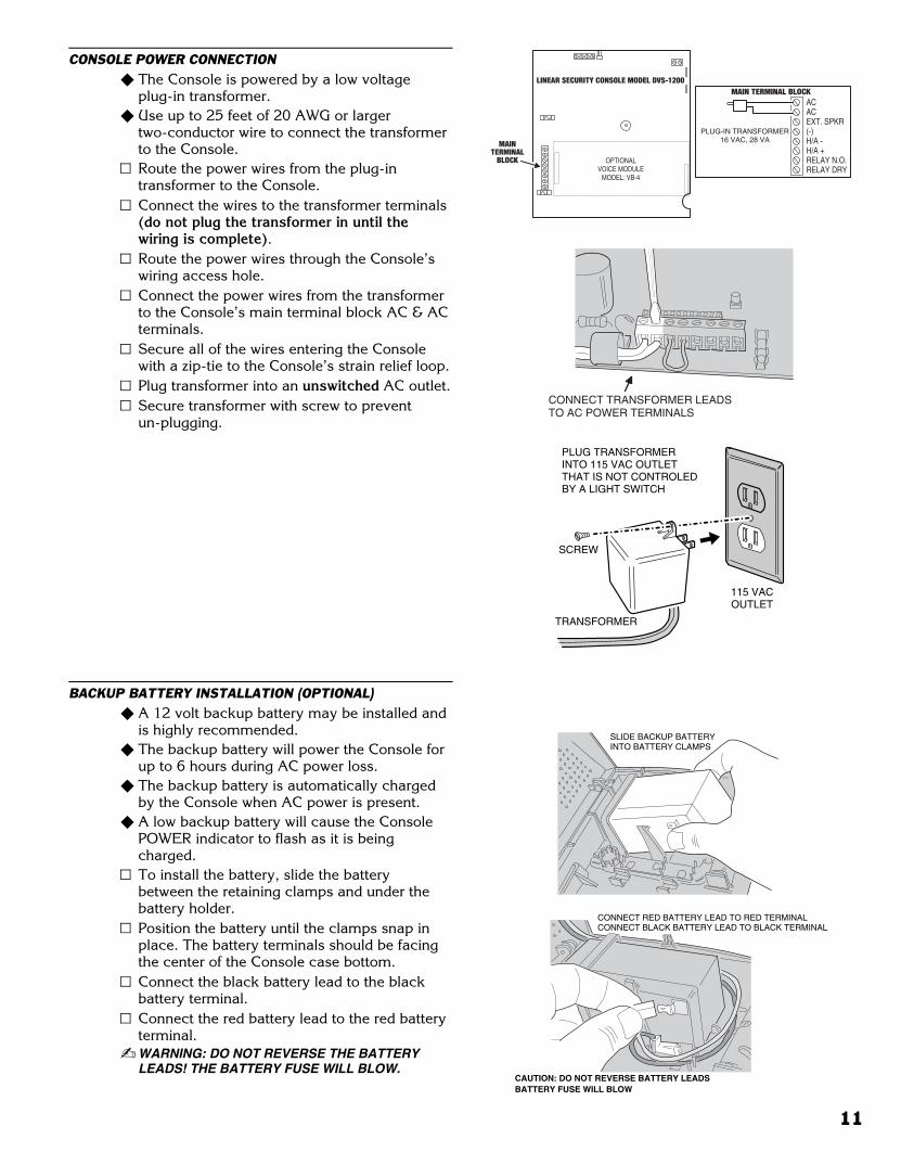
CONSOLE POWER CONNECTION� The Console is powered by a low voltage
plug-in transformer.� Use up to 25 feet of 20 AWG or larger
two-conductor wire to connect the transformerto the Console.Route the power wires from the plug-intransformer to the Console.Connect the wires to the transformer terminals(do not plug the transformer in until thewiring is complete).Route the power wires through the Console’swiring access hole.Connect the power wires from the transformerto the Console’s main terminal block AC & ACterminals.Secure all of the wires entering the Consolewith a zip-tie to the Console’s strain relief loop.Plug transformer into an unswitched AC outlet.Secure transformer with screw to preventun-plugging.
BACKUP BATTERY INSTALLATION (OPTIONAL)� A 12 volt backup battery may be installed and
is highly recommended.� The backup battery will power the Console for
up to 6 hours during AC power loss.� The backup battery is automatically charged
by the Console when AC power is present.� A low backup battery will cause the Console
POWER indicator to flash as it is beingcharged.To install the battery, slide the batterybetween the retaining clamps and under thebattery holder.Position the battery until the clamps snap inplace. The battery terminals should be facingthe center of the Console case bottom.Connect the black battery lead to the blackbattery terminal.Connect the red battery lead to the red batteryterminal.
� WARNING: DO NOT REVERSE THE BATTERYLEADS! THE BATTERY FUSE WILL BLOW.
CONNECT TRANSFORMER LEADSTO AC POWER TERMINALS
ACACEXT. SPKR(-)H/A -H/A +RELAY N.O.RELAY DRY
MAIN TERMINAL BLOCK
OPTIONALVOICE MODULE
MODEL: VB-4
MAINTERMINAL
BLOCK
LINEAR SECURITY CONSOLE MODEL DVS-1200
PLUG-IN TRANSFORMER16 VAC, 28 VA
TRANSFORMER
115 VACOUTLET
PLUG TRANSFORMERINTO 115 VAC OUTLETTHAT IS NOT CONTROLED BY A LIGHT SWITCH
SCREW
SLIDE BACKUP BATTERYINTO BATTERY CLAMPS
CONNECT RED BATTERY LEAD TO RED TERMINALCONNECT BLACK BATTERY LEAD TO BLACK TERMINAL
CAUTION: DO NOT REVERSE BATTERY LEADSBATTERY FUSE WILL BLOW
11
Black 0014
Black0014
6. BASIC CONSOLE PROGRAMMING
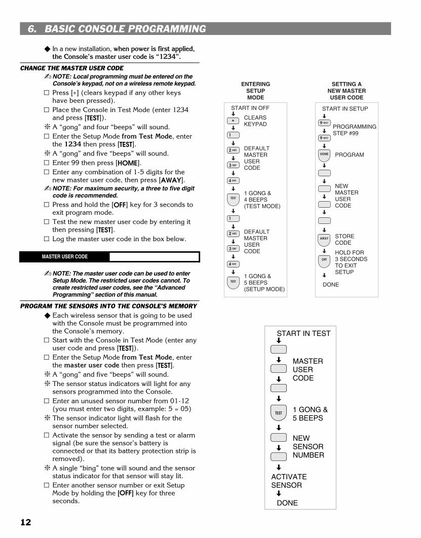
� In a new installation, when power is first applied,the Console’s master user code is “1234”.
CHANGE THE MASTER USER CODE� NOTE: Local programming must be entered on the
Console’s keypad, not on a wireless remote keypad.
Press [∗] (clears keypad if any other keyshave been pressed).Place the Console in Test Mode (enter 1234and press [TEST]).
� A “gong” and four “beeps” will sound.Enter the Setup Mode from Test Mode, enterthe 1234 then press [TEST].
� A “gong” and five “beeps” will sound.Enter 99 then press [HOME].Enter any combination of 1-5 digits for thenew master user code, then press [AWAY].
� NOTE: For maximum security, a three to five digitcode is recommended.
Press and hold the [OFF] key for 3 seconds toexit program mode.Test the new master user code by entering itthen pressing [TEST].Log the master user code in the box below.
MASTER USER CODE
� NOTE: The master user code can be used to enterSetup Mode. The restricted user codes cannot. Tocreate restricted user codes, see the “AdvancedProgramming” section of this manual.
PROGRAM THE SENSORS INTO THE CONSOLE’S MEMORY� Each wireless sensor that is going to be used
with the Console must be programmed intothe Console’s memory.Start with the Console in Test Mode (enter anyuser code and press [TEST]).Enter the Setup Mode from Test Mode, enterthe master user code then press [TEST].
� A “gong” and five “beeps” will sound.� The sensor status indicators will light for any
sensors programmed into the Console.Enter an unused sensor number from 01-12(you must enter two digits, example: 5 = 05)
� The sensor indicator light will flash for thesensor number selected.Activate the sensor by sending a test or alarmsignal (be sure the sensor’s battery isconnected or that its battery protection strip isremoved).
� A single “bing” tone will sound and the sensorstatus indicator for that sensor will stay lit.Enter another sensor number or exit SetupMode by holding the [OFF] key for threeseconds.
START IN OFF
DEFAULTMASTERUSERCODE
1 GONG &4 BEEPS(TEST MODE)
START IN SETUP
PROGRAMMINGSTEP #99
NEWMASTERUSERCODE
DONE
HOLD FOR3 SECONDSTO EXITSETUP
STORECODE
ENTERINGSETUPMODE
CLEARSKEYPAD
DEFAULTMASTERUSERCODE
1 GONG &5 BEEPS(SETUP MODE)
SETTING ANEW MASTERUSER CODE
PROGRAM
START IN TEST
MASTERUSERCODE
1 GONG &5 BEEPS
NEWSENSORNUMBER
ACTIVATESENSOR
DONE
TEST
12
Black 0015
Black0015
PROGRAMMING DIFFERENT SENSOR TYPES� Follow the instructions on the previous page to
select a sensor number to program the sensorinto.
� NOTE: A sensor can be programmed into more thanone location. Be sure to choose an unused sensornumber. If a sensor gets entered into more than onelocation, delete the duplicates using the removesensor function.
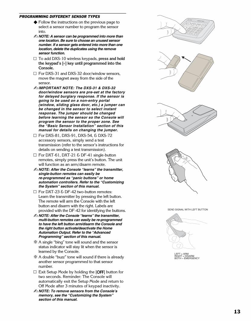
To add DXS-10 wireless keypads, press and holdthe keypad’s [∗] key until programmed into theConsole.For DXS-31 and DXS-32 door/window sensors,move the magnet away from the side of thesensor.
� IMPORTANT NOTE: The DXS-31 & DXS-32door/window sensors are pre-set at the factoryfor delayed burglary response. If the sensor isgoing to be used on a non-entry portal(window, sliding glass door, etc.) a jumper canbe changed in the sensor to select instantresponse. The jumper should be changedbefore learning the sensor so the Console willprogram the sensor to the proper zone. Seethe “Basic Sensor Installation” section of thismanual for details on changing the jumper.
For DXS-81, DXS-91, DXS-54, & DXS-72accessory sensors, simply send a testtransmission (refer to the sensor’s instructions fordetails on sending a test transmission).For DXT-61, DXT-21 & DF-41 single-buttonremotes, simply press the unit’s button. The unitwill function as an arm/disarm remote.
� NOTE: After the Console “learns” the transmitter,single-button remotes can easily bere-programmed as “panic buttons” or homeautomation controllers. Refer to the “Customizingthe System” section of this manual.
For DXT-23 & DF-42 two-button remotes: Learn the transmitter by pressing the left button.The remote will arm the Console with the leftbutton and disarm with the right. Labels areprovided with the DF-42 for identifying the buttons.
� NOTE: After the Console “learns” the transmitter,multi-button remotes can easily be re-programmedto have the left button arm/disarm the Console andthe right button activate/deactivate the HomeAutomation Output. Refer to the “AdvancedProgramming” section of this manual.
� A single “bing” tone will sound and the sensorstatus indicator will stay lit when the sensor islearned by the Console.
� A double “buzz” tone will sound if there is alreadyanother sensor programmed to that sensornumber.Exit Setup Mode by holding the [OFF] button fortwo seconds. Reminder: The Console willautomatically exit the Setup Mode and return toOff Mode after 3 minutes of keypad inactivity.
� NOTE: To remove sensors from the Console’smemory, see the “Customizing the System”section of this manual.
SEND SIGNAL WITH LEFT BUTTON
LEFT = ARMRIGHT = DISARMBOTH = EMERGENCY
13
Black 0016
Black0016
7. BASIC SENSOR INSTALLATION
� Each accessory sensor is packaged with itsown set of installation instructions specific tothe model of sensor.
� Refer to the sensor’s instructions for details oninstalling, operating, and testing of the sensor.
� Following are basic instructions for installingtwo popular DVS-1200 accessories: TheModel DXS-10 Wireless Remote Keypad andthe Model DXS-31 Door/Window Transmitter.
DXS-10 WIRELESS KEYPAD� The DXS-10 is used to remotely command the
Console.� The keypad can be simply set on a table or
mounted to a flat surface.TABLE-TOP USE
� Four anti-mar pads are provided as scratchdeterrent “feet” for the keypad.
� NOTE: Do not use the adhesive “feet” if thekeypad is going to be wall mounted.
Peel off the adhesive tape backing on the“feet” and stick them to the back of thekeypad.
� The wireless keypad can be used as aportable keypad. Because of the hourlysupervisory transmissions, if the unit is takenout of range from the Console for more thaneight hours, the Console will indicate “radiotrouble” for the keypad. The keypad’s sensornumber can be programmed for“non-supervised” if required. See the“Advanced Programming” section of thismanual.
WALL MOUNT USE� The wireless keypad can be wall mounted in a
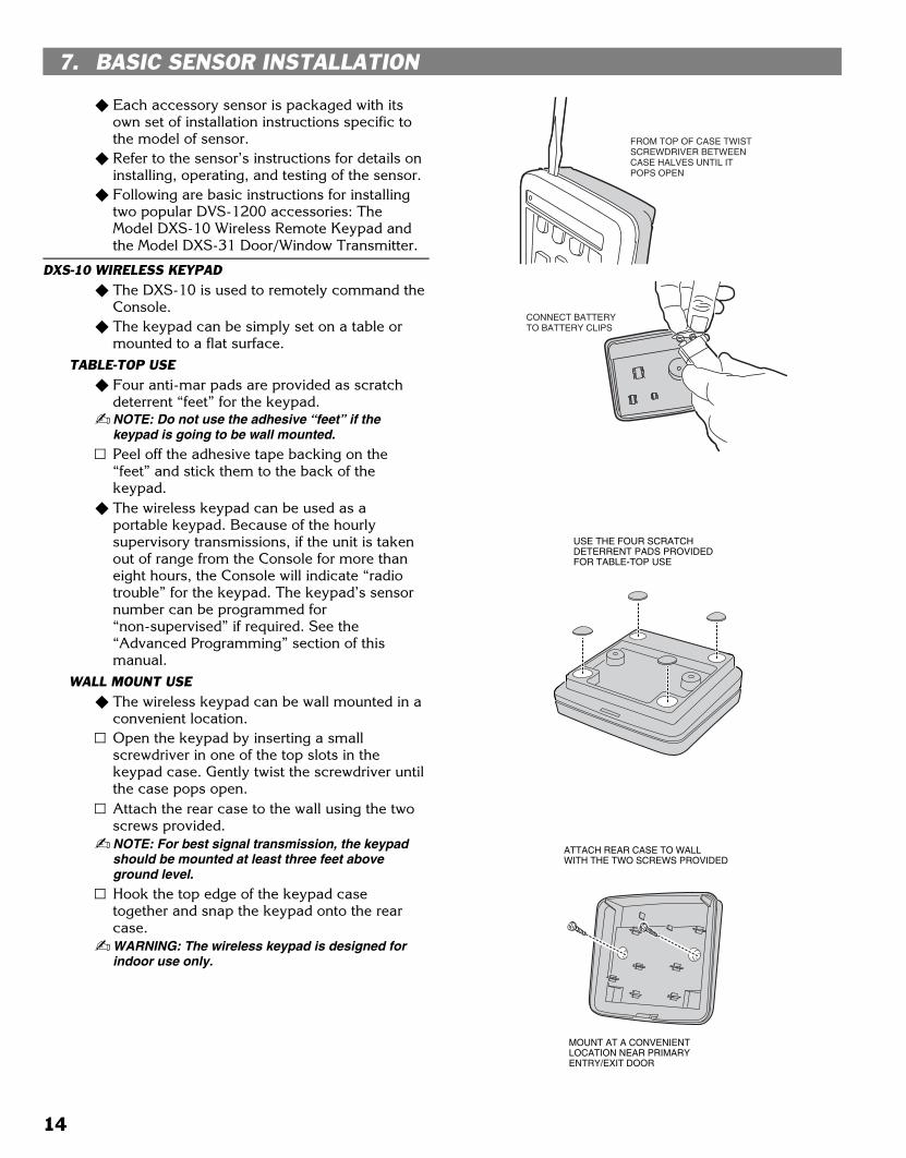
convenient location.Open the keypad by inserting a smallscrewdriver in one of the top slots in thekeypad case. Gently twist the screwdriver untilthe case pops open.Attach the rear case to the wall using the twoscrews provided.
� NOTE: For best signal transmission, the keypadshould be mounted at least three feet aboveground level.
Hook the top edge of the keypad casetogether and snap the keypad onto the rearcase.
� WARNING: The wireless keypad is designed forindoor use only.
USE THE FOUR SCRATCHDETERRENT PADS PROVIDEDFOR TABLE-TOP USE
FROM TOP OF CASE TWISTSCREWDRIVER BETWEENCASE HALVES UNTIL ITPOPS OPEN
CONNECT BATTERYTO BATTERY CLIPS
ATTACH REAR CASE TO WALLWITH THE TWO SCREWS PROVIDED
MOUNT AT A CONVENIENTLOCATION NEAR PRIMARY ENTRY/EXIT DOOR
14

Black 0017
Black0017
DXS-31 & DXS-32 DOOR/WINDOW SENSORS� The DXS-31 & DXS-32 sensors can be used
to monitor doors, windows, cabinets, crawlspace doors, gates, freezer doors, and manyother moving objects that could be used forintrusion or need to be monitored.
� A built-in magnetic switch triggers the sensorwhen its magnet (mounted on the moving partor the door or window) moves away from thesensor.
� External normally closed switches can bewired to the sensor for remote triggering.
� The door/window sensor can connect directlyto a glass break detector.
SET SENSOR JUMPER� A jumper inside the door/window sensor
selects instant or delayed response.If the sensor is going to be used on theprimary entry/exit door make sure that thejumper is in the DELAY position.If the sensor is going to be used on a windowor a door that is not going to be used to enterand exit the premises, set the jumper to theINSTANT position.
APPLY DOUBLE-STICK TAPEApply double-stick tape (supplied) to back ofsensors and magnets.
� Screws are also provided to mount sensorsand magnets.
� Screws are preferred over the double-sticktape in permanent installations.
� UL NOTE: Double-stick tape is not allowed in ULinstallations.
ATTACH SENSORS AND MAGNETSOn doors, mount sensor to door frame andmagnet to door.
� NOTE: Magnet must line up with mark on sensorcase both horizontally & vertically.
Allow a maximum of 1/2" between magnetand sensor when door/window is closed.Snap sensor onto mounting plate.On windows, mount sensor to window frameand magnet to window.Snap sensor onto mounting plate.The magnet height is adjustable and anoptional magnet spacer is provided for unevensurfaces.
TEST SENSORS� Console in Chime Mode should “ding-dong”
when the sensor sends signal.Open door or window.
� Verify that light on the sensor glowsmomentarily when door/window is opened.
� Status indicator on Console should remain litfor each door/window sensor that is left open.
TRANSMITTERMOUNTED ONDOOR JAMB
(NOTE: SMALL ENDOF TRANSMITTER UP)
(NOTE: SMALL ENDOF TRANSMITTER DOWN)
MAGNETMOUNTEDON DOOR
MAGNET MOUNTEDON DOOR
TRANSMITTERMOUNTED ONWINDOW SILL
MAGNET MOUNTEDON WINDOW FRAME
SLIDING WINDOWLEFT OPENING DOOR
RIGHT OPENING DOOR
TRANSMITTERMOUNTED ONDOOR JAMB
TRANSMITTERMOUNTED ONWINDOW FRAME
MAGNETMOUNTEDON WINDOWSASH STILE
DOUBLE-HUNGWINDOW
EXAMPLE INSTALLATIONS (WITH DXS-31 SHOWN)
TRANSMITINDICATOR
INPUTSELECTJUMPER
INSTANT/DELAYOPTION JUMPER
ANTENNA
MAGNETALIGNMENTMARK
TWO TYPE 2032BATTERIES
BATTERY CLAMP
EXTERNALINPUTTERMINALS
TESTSWITCH
BATTERYCLAMPSCREW
INSTANT/DELAYOPTION JUMPER
SELECTSDELAY
SELECTSINSTANT
ATTACH MOUNTING PLATESUSING THE SCREWS ORDOUBLE-STICK TAPE PROVIDED
NOTE: ATTACHING THE TRANSMITTER WITH DOUBLE-STICKTAPE IS NOT ALLOWED IN UL INSTALLATIONS
1. PLACE RECEIVER INTO PROGRAM OR "LEARN" MODE
2. ACTIVATE TRANSMITTER BY OPENING DOOR OR WINDOW
3. VERIFY THAT THE RECEIVER ACCEPTED THE SIGNAL
4. REPLACE TRANSMITTER COVER WHEN FINISHED
NOTE: THE TRANSMIT INDICATOR WILL ONLY LIGHT DURING TRANSMISSIONS WHEN THE CASE IS OPEN (EXCEPT WHEN PUSHING THE CASE FOR TESTING)
OPEN DOOR, TRANSMITINDICATOR SHOULD LIGHT
15
Black 0018
Black0018
8. CUSTOMIZING THE CONSOLE
� The Console can be customized for thespecific installation.
� A label sheet with sensor location names isprovided with the Console.
� Labeling the sensors allows quick and easyidentification of where any alarms haveoccurred, where a sensor with a low battery is,where a sensor with radio trouble is, etc.
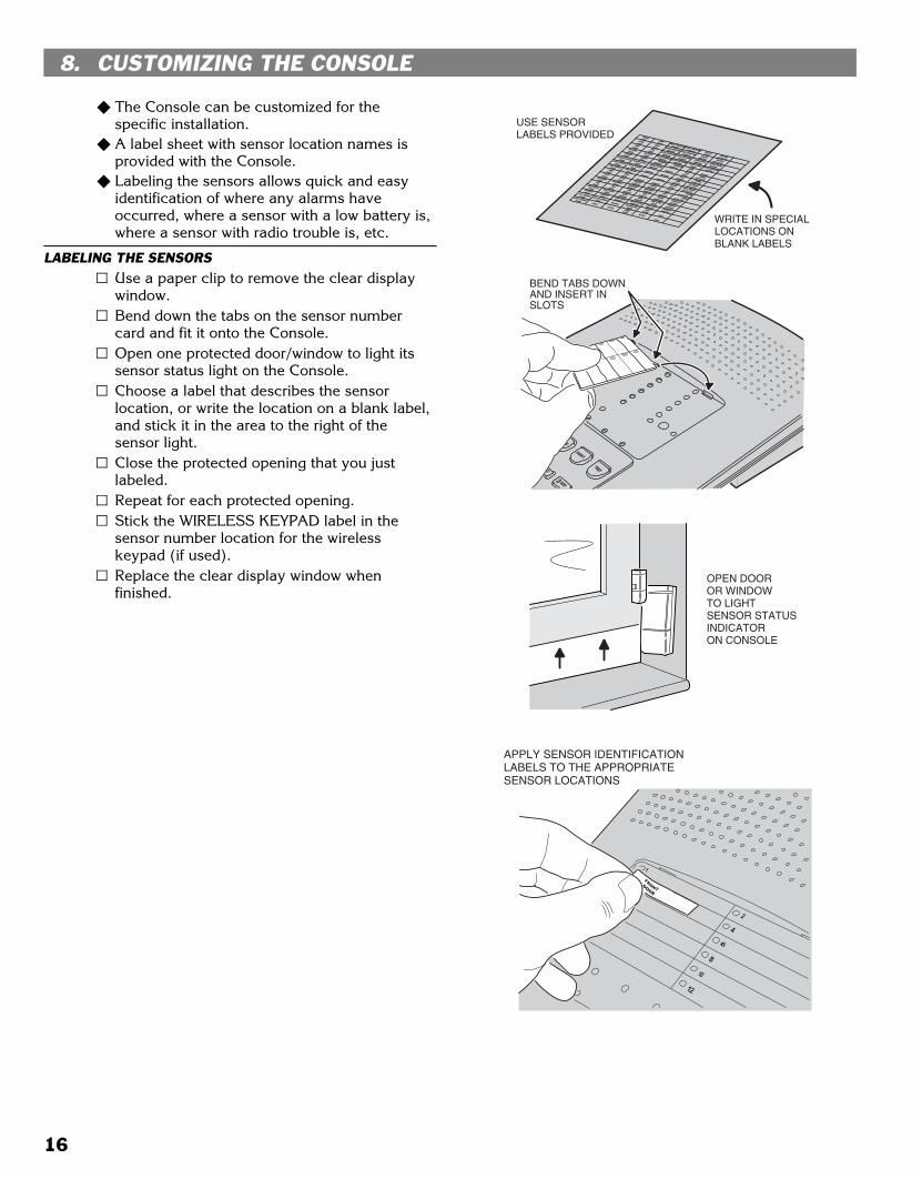
LABELING THE SENSORSUse a paper clip to remove the clear displaywindow.Bend down the tabs on the sensor numbercard and fit it onto the Console.Open one protected door/window to light itssensor status light on the Console.Choose a label that describes the sensorlocation, or write the location on a blank label,and stick it in the area to the right of thesensor light.Close the protected opening that you justlabeled.Repeat for each protected opening.Stick the WIRELESS KEYPAD label in thesensor number location for the wirelesskeypad (if used).Replace the clear display window whenfinished.
OPEN DOOROR WINDOWTO LIGHTSENSOR STATUSINDICATORON CONSOLE
APPLY SENSOR IDENTIFICATIONLABELS TO THE APPROPRIATESENSOR LOCATIONS
BEND TABS DOWN AND INSERT IN SLOTS
USE SENSOR LABELS PROVIDED
WRITE IN SPECIALLOCATIONS ONBLANK LABELS
16
Black 0019
Black0019
9. CONSOLE OPERATING MODES
OFF MODE� Use this mode to disarm the burglary portion
of the system.� Switching to Off Mode stops any alarms in
progress.� The 24-hour functions are still active in Off
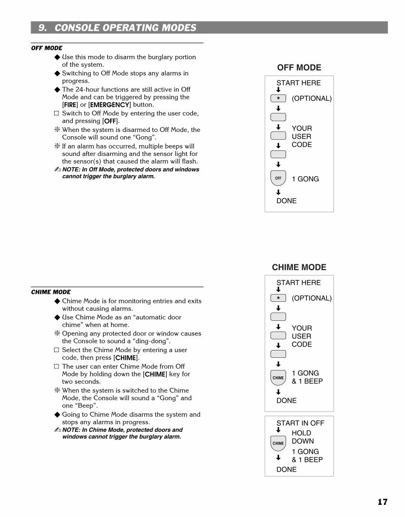
Mode and can be triggered by pressing the[FIRE] or [EMERGENCY] button.Switch to Off Mode by entering the user code,and pressing [OFF].
� When the system is disarmed to Off Mode, theConsole will sound one “Gong”.
� If an alarm has occurred, multiple beeps willsound after disarming and the sensor light forthe sensor(s) that caused the alarm will flash.
� NOTE: In Off Mode, protected doors and windowscannot trigger the burglary alarm.
CHIME MODE� Chime Mode is for monitoring entries and exits
without causing alarms.� Use Chime Mode as an “automatic door
chime” when at home.� Opening any protected door or window causes
the Console to sound a “ding-dong”.Select the Chime Mode by entering a usercode, then press [CHIME].The user can enter Chime Mode from OffMode by holding down the [CHIME] key fortwo seconds.
� When the system is switched to the ChimeMode, the Console will sound a “Gong” andone “Beep”.
� Going to Chime Mode disarms the system andstops any alarms in progress.
� NOTE: In Chime Mode, protected doors andwindows cannot trigger the burglary alarm.
START HERE
YOURUSERCODE
DONE
1 GONG
(OPTIONAL)
OFF
OFF MODE
START IN OFF
DONE
1 GONG& 1 BEEP
HOLDDOWN
CHIME
START HERE
YOURUSERCODE
DONE
1 GONG& 1 BEEP
(OPTIONAL)
CHIME MODE
CHIME
17

Black 0020
Black0020
HOME MODE� Use this mode when sleeping or when anyone
is staying inside.� Home Mode causes an instant alarm when
any perimeter sensor is triggered.� Home Mode causes a delayed alarm when any
exit/entry sensor is triggered (except in HomeInstant Mode when they are instant).
� Alarm siren stops automatically after fiveminutes and the system will remain armed.
� Home Mode ignores all interior sensors(motion detectors, etc.).Arm to Home Mode by entering a user code,and pressing [HOME].The user can “Quick Arm” to Home Mode fromOff or Chime Mode by holding down the [HOME]key for two seconds. (Quick arming can bedisabled; see the “Advanced Programming”section of this manual.)
� When the system is armed to the Home Mode,the Console will sound a “Gong” and two “Beeps”.Enter a user code and press [OFF] or [CHIME] todisarm from Home Mode and/or stop the alarmsiren.
� If an alarm has occurred, multiple beeps willsound after disarming and the sensor light forthe sensor(s) that caused the alarm will flash(switch to Off Mode again or re-arm the Consoleto stop the flashing alarm memory light).
SECURE EXITIf the system is already in the Home Mode andthe user wants to exit the premises whileleaving someone inside with the system still inHome Mode, enter a user code and press the[HOME] key.
� A “gong” and two “beeps” will sound and theHOME light will blink for 60 seconds. No exitdelay beeps will sound during the Exit Delay.
� The user can leave through a door with a delayedperimeter sensor during the 60 second Exit Delaywithout causing the Console to begin an EntryDelay.
� Re-entering during the silent Exit Delay willextend the Exit Delay another 60 seconds(one time only).
� NOTE: The Exit Delay time can be changed; seethe “Advanced Programming” section of thismanual.
HOME INSTANT MODEIf the system is already in the Home Mode andthe user wants to make all exit/entry sensorsinstant, press the [HOME] key for 2 seconds.
� Two “gongs” and two “beeps” will sound andthe HOME light will blink continuously.
� Because all exit/entry sensors will now cause aninstant alarm when in Home Mode, theConsole must be disarmed before opening anyexit/entry delay door.
MANUAL BYPASSING OF SENSORS� Manual bypassing of sensors in the Home
Mode allows arming of the system at nightwith open windows, while still havingperimeter protection with other closed doorsand windows.
� The Console will resist arming with open dooror window sensors.
� Four high-low beeps to warn the user thatsomething is open and the system will remainin the previous mode.
� Lit sensor status indicators show whichsensors are open.To manually bypass the open sensors, armthe system again within 5 seconds.
� A “gong” and two “beeps” will sound, theHOME indicator will light, and the opensensors will be bypassed.
� WARNING: Bypassed sensors cannot cause analarm.
START IN OFFOR CHIME MODE
YOURUSERCODE
DONE
1 GONG& 2 BEEPS
(OPTIONAL)
HOME MODE
HOME
START INHOME MODE
YOURUSERCODE
DONE
1 GONG& 2 BEEPS
(OPTIONAL)
HOME
SECURE EXIT
START INHOME MODE
DONE
2 GONGS& 2 BEEPS
HOLDDOWN
HOME INSTANTMODE
HOME
DONE
1 GONG& 2 BEEPS
HOLDDOWNHOME
START IN OFFOR CHIME MODE
QUICK ARM
18

Black 0021
Black0021
AWAY MODE� Use this mode when no one will be staying home.� Each burglary sensor can trigger the siren once
per arming period.� Away Mode causes an instant alarm when any
perimeter sensor is triggered.� Away Mode causes a delayed alarm when any
exit/entry sensor is triggered.� Away Mode causes an instant alarm when any
interior sensors (motion detectors, etc.) aretriggered. The interior sensors will be delayed if aperimeter delayed sensor is triggered first.
� Alarm siren stops automatically after five minutesand the system will remain armed.Arm to Away Mode by entering a user code, andpressing [AWAY].The user can “Quick Arm” to Away Mode fromHome, Chime or Off Mode by holding down the[AWAY] key for two seconds. (Quick arming canbe disabled; see the “Advanced Programming”section of this manual.)
EXIT DELAY (For Leaving the Premises)� When the system is armed to the Away Mode, the
Console will sound a “Gong” and three “Beeps”.� During the 60 second Exit Delay, the Console will
sound “beeps” (double beeps last 10 seconds) andthe AWAY light will blink.
� The Exit Delay gives the user 60 seconds to leavethe premises through an exit/entry door withouttriggering an alarm.
� Re-entering during the Exit Delay will extend theExit Delay another 60 seconds (one time only).
� When the Exit Delay is over, the Console willsound one “gong” to warn the user that thesystem is fully armed.
� NOTE: The Exit Delay time can be changed; see the“Advanced Programming” section of this manual.
ENTRY DELAY (For Entering the Premises)� The Entry Delay gives the user 30 seconds to
enter the premises through an exit/entry doorwithout triggering an alarm.
� If a exit/entry sensor is triggered, starting the EntryDelay, the interior sensors will also becomedelayed (this allows motion in the premises duringthe Entry Delay).
� During the 30 second Entry Delay, the Consolewill sound “beeps”.
� When the Entry Delay is over, the Console will gointo full alarm and sound the siren if it is notdisarmed to the Off or Chime Mode.
� If an alarm has occurred while the user was gone,multiple beeps will sound after disarming and thesensor light for the sensor(s) that caused the alarmwill flash (switch to Off Mode again or re-arm theConsole to stop the flashing alarm memory light).
� NOTE: The Entry Delay time can be changed; see the“Advanced Programming” section of this manual.
MANUAL BYPASSING OF SENSORS� Manual bypassing of sensors in the Away
Mode allows arming of the system with opendoors and windows, while still havingperimeter protection with other closed doorsand windows.
� The Console will resist arming with open dooror window sensors.
� Four high-low beeps to warn the user thatsomething is open and the system will remainin the previous mode.
� Lit sensor status indicators show whichsensors are open.To manually bypass the open sensors, armthe system again within 5 seconds.
� A “gong” and three “beeps” will sound, theAWAY indicator will light, and the opensensors will be bypassed.
� WARNING: Bypassed sensors cannot cause analarm.
START HERE
DONE
1 GONG& 3 BEEPS
HOLDDOWN
START HERE
YOURUSERCODE
DONE
1 GONG& 3 BEEPS
(OPTIONAL)
AWAY MODE
AWAY
AWAY
QUICK ARM
19
Black 0022
Black0022
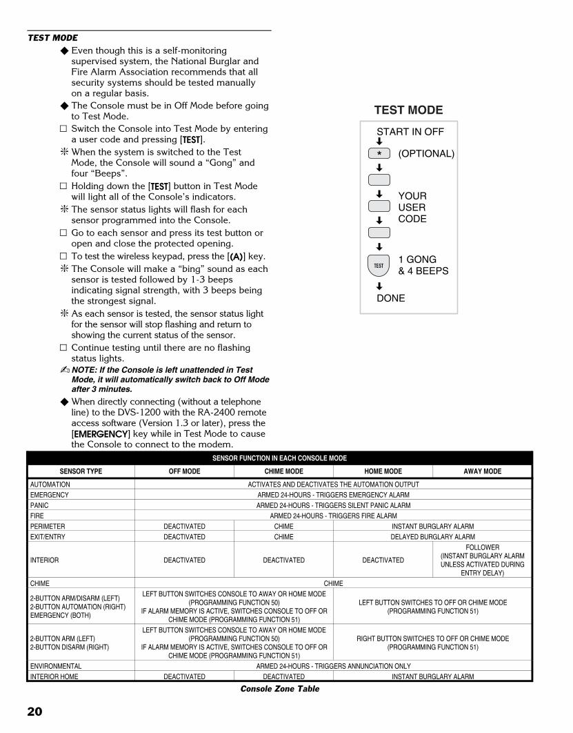
TEST MODE� Even though this is a self-monitoring
supervised system, the National Burglar andFire Alarm Association recommends that allsecurity systems should be tested manuallyon a regular basis.
� The Console must be in Off Mode before goingto Test Mode.Switch the Console into Test Mode by enteringa user code and pressing [TEST].
� When the system is switched to the TestMode, the Console will sound a “Gong” andfour “Beeps”.Holding down the [TEST] button in Test Modewill light all of the Console’s indicators.
� The sensor status lights will flash for eachsensor programmed into the Console.Go to each sensor and press its test button oropen and close the protected opening.To test the wireless keypad, press the [(A)] key.
� The Console will make a “bing” sound as eachsensor is tested followed by 1-3 beepsindicating signal strength, with 3 beeps beingthe strongest signal.
� As each sensor is tested, the sensor status lightfor the sensor will stop flashing and return toshowing the current status of the sensor.Continue testing until there are no flashingstatus lights.
� NOTE: If the Console is left unattended in TestMode, it will automatically switch back to Off Modeafter 3 minutes.
� When directly connecting (without a telephoneline) to the DVS-1200 with the RA-2400 remoteaccess software (Version 1.3 or later), press the[EMERGENCY] key while in Test Mode to causethe Console to connect to the modem.
START IN OFF
YOURUSERCODE
DONE
1 GONG& 4 BEEPS
(OPTIONAL)
TEST MODE
TEST
SENSOR FUNCTION IN EACH CONSOLE MODE
SENSOR TYPE OFF MODE CHIME MODE HOME MODE AWAY MODE
AUTOMATION ACTIVATES AND DEACTIVATES THE AUTOMATION OUTPUTEMERGENCY ARMED 24-HOURS - TRIGGERS EMERGENCY ALARMPANIC ARMED 24-HOURS - TRIGGERS SILENT PANIC ALARMFIRE ARMED 24-HOURS - TRIGGERS FIRE ALARMPERIMETER DEACTIVATED CHIME INSTANT BURGLARY ALARMEXIT/ENTRY DEACTIVATED CHIME DELAYED BURGLARY ALARM
INTERIOR DEACTIVATED DEACTIVATED DEACTIVATED
FOLLOWER(INSTANT BURGLARY ALARMUNLESS ACTIVATED DURING
ENTRY DELAY)CHIME CHIME
2-BUTTON ARM/DISARM (LEFT)2-BUTTON AUTOMATION (RIGHT)EMERGENCY (BOTH)
LEFT BUTTON SWITCHES CONSOLE TO AWAY OR HOME MODE(PROGRAMMING FUNCTION 50)
IF ALARM MEMORY IS ACTIVE, SWITCHES CONSOLE TO OFF ORCHIME MODE (PROGRAMMING FUNCTION 51)
LEFT BUTTON SWITCHES TO OFF OR CHIME MODE(PROGRAMMING FUNCTION 51)
2-BUTTON ARM (LEFT)2-BUTTON DISARM (RIGHT)
LEFT BUTTON SWITCHES CONSOLE TO AWAY OR HOME MODE(PROGRAMMING FUNCTION 50)
IF ALARM MEMORY IS ACTIVE, SWITCHES CONSOLE TO OFF ORCHIME MODE (PROGRAMMING FUNCTION 51)
RIGHT BUTTON SWITCHES TO OFF OR CHIME MODE(PROGRAMMING FUNCTION 51)
ENVIRONMENTAL ARMED 24-HOURS - TRIGGERS ANNUNCIATION ONLYINTERIOR HOME DEACTIVATED DEACTIVATED INSTANT BURGLARY ALARM
Console Zone Table
20
Black 0023
Black0023
10.SYSTEM TROUBLE INDICATIONS
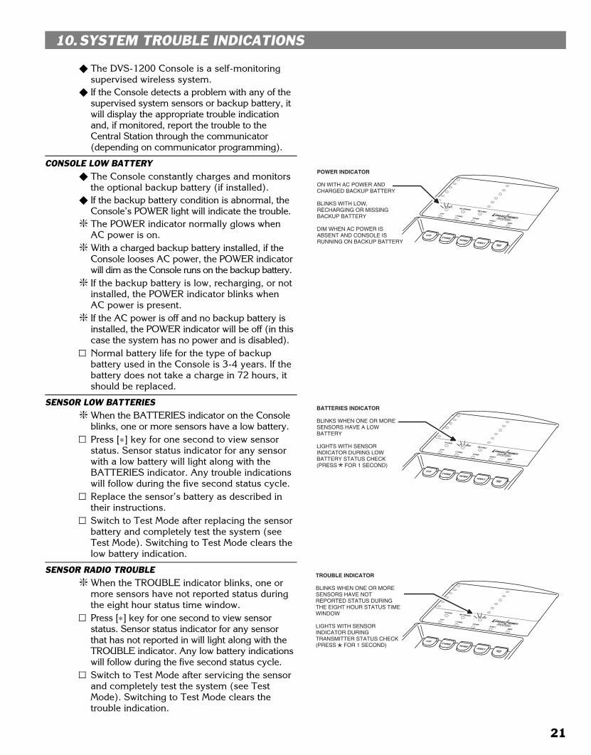
� The DVS-1200 Console is a self-monitoringsupervised wireless system.
� If the Console detects a problem with any of thesupervised system sensors or backup battery, itwill display the appropriate trouble indicationand, if monitored, report the trouble to theCentral Station through the communicator(depending on communicator programming).
CONSOLE LOW BATTERY� The Console constantly charges and monitors
the optional backup battery (if installed).� If the backup battery condition is abnormal, the
Console’s POWER light will indicate the trouble.� The POWER indicator normally glows when
AC power is on.� With a charged backup battery installed, if the
Console looses AC power, the POWER indicatorwill dim as the Console runs on the backup battery.
� If the backup battery is low, recharging, or notinstalled, the POWER indicator blinks whenAC power is present.
� If the AC power is off and no backup battery isinstalled, the POWER indicator will be off (in thiscase the system has no power and is disabled).Normal battery life for the type of backupbattery used in the Console is 3-4 years. If thebattery does not take a charge in 72 hours, itshould be replaced.
SENSOR LOW BATTERIES� When the BATTERIES indicator on the Console
blinks, one or more sensors have a low battery.Press [∗] key for one second to view sensorstatus. Sensor status indicator for any sensorwith a low battery will light along with theBATTERIES indicator. Any trouble indicationswill follow during the five second status cycle.Replace the sensor’s battery as described intheir instructions.Switch to Test Mode after replacing the sensorbattery and completely test the system (seeTest Mode). Switching to Test Mode clears thelow battery indication.
SENSOR RADIO TROUBLE� When the TROUBLE indicator blinks, one or
more sensors have not reported status duringthe eight hour status time window. Press [∗] key for one second to view sensorstatus. Sensor status indicator for any sensorthat has not reported in will light along with theTROUBLE indicator. Any low battery indicationswill follow during the five second status cycle.Switch to Test Mode after servicing the sensorand completely test the system (see TestMode). Switching to Test Mode clears thetrouble indication.
POWER INDICATOR
ON WITH AC POWER AND CHARGED BACKUP BATTERY
BLINKS WITH LOW, RECHARGING OR MISSING BACKUP BATTERY
DIM WHEN AC POWER IS ABSENT AND CONSOLE IS RUNNING ON BACKUP BATTERY
BATTERIES INDICATOR
BLINKS WHEN ONE OR MORE SENSORS HAVE A LOW BATTERY
LIGHTS WITH SENSOR INDICATOR DURING LOW BATTERY STATUS CHECK(PRESS FOR 1 SECOND)
TROUBLE INDICATOR
BLINKS WHEN ONE OR MORE SENSORS HAVE NOT REPORTED STATUS DURING THE EIGHT HOUR STATUS TIME WINDOW
LIGHTS WITH SENSOR INDICATOR DURING TRANSMITTER STATUS CHECK(PRESS FOR 1 SECOND)
21
Black 0024
Black0024
11.CUSTOMIZING THE SYSTEM
� Adding additional sensors will increase theprotection provided by the system.
� All ground-level perimeter openings andaccessible upper-story openings needprotection.
� Motion detectors can protect interior areasand areas where valuables are kept.
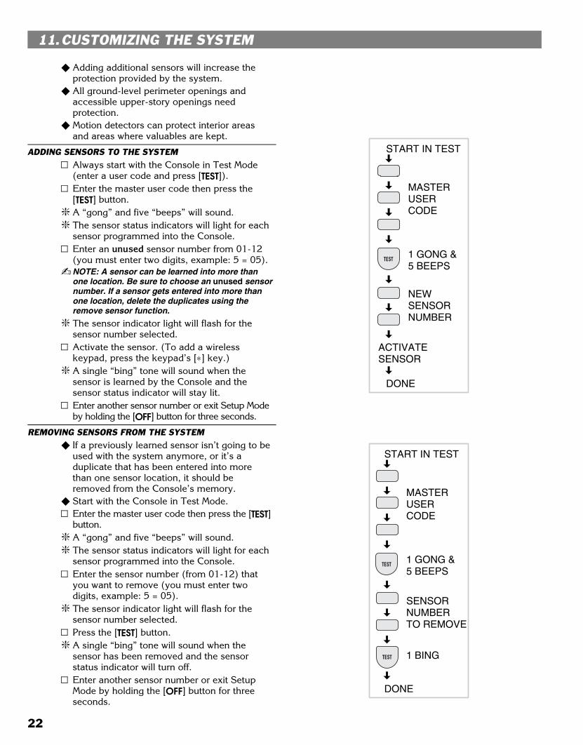
ADDING SENSORS TO THE SYSTEMAlways start with the Console in Test Mode(enter a user code and press [TEST]).Enter the master user code then press the[TEST] button.
� A “gong” and five “beeps” will sound.� The sensor status indicators will light for each
sensor programmed into the Console.Enter an unused sensor number from 01-12(you must enter two digits, example: 5 = 05).
� NOTE: A sensor can be learned into more thanone location. Be sure to choose an unused sensornumber. If a sensor gets entered into more thanone location, delete the duplicates using theremove sensor function.
� The sensor indicator light will flash for thesensor number selected.Activate the sensor. (To add a wirelesskeypad, press the keypad’s [∗] key.)
� A single “bing” tone will sound when thesensor is learned by the Console and thesensor status indicator will stay lit.Enter another sensor number or exit Setup Modeby holding the [OFF] button for three seconds.
REMOVING SENSORS FROM THE SYSTEM� If a previously learned sensor isn’t going to be
used with the system anymore, or it’s aduplicate that has been entered into morethan one sensor location, it should beremoved from the Console’s memory.
� Start with the Console in Test Mode.Enter the master user code then press the [TEST]button.
� A “gong” and five “beeps” will sound.� The sensor status indicators will light for each
sensor programmed into the Console.Enter the sensor number (from 01-12) thatyou want to remove (you must enter twodigits, example: 5 = 05).
� The sensor indicator light will flash for thesensor number selected.Press the [TEST] button.
� A single “bing” tone will sound when thesensor has been removed and the sensorstatus indicator will turn off.Enter another sensor number or exit SetupMode by holding the [OFF] button for threeseconds.
START IN TEST
MASTERUSERCODE
1 GONG &5 BEEPS
NEWSENSORNUMBER
ACTIVATESENSOR
DONE
TEST
START IN TEST
MASTERUSERCODE
1 GONG &5 BEEPS
SENSORNUMBERTO REMOVE
DONE
TEST
TEST 1 BING
22
Black 0025
Black0025
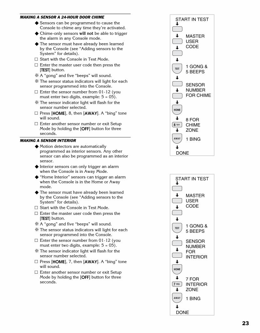
MAKING A SENSOR A 24-HOUR DOOR CHIME� Sensors can be programmed to cause the
Console to chime any time they’re activated.� Chime-only sensors will not be able to trigger
the alarm in any Console mode.� The sensor must have already been learned
by the Console (see “Adding sensors to theSystem” for details).Start with the Console in Test Mode.Enter the master user code then press the[TEST] button.
� A “gong” and five “beeps” will sound.� The sensor status indicators will light for each
sensor programmed into the Console.Enter the sensor number from 01-12 (youmust enter two digits, example: 5 = 05).
� The sensor indicator light will flash for thesensor number selected.Press [HOME], 8, then [AWAY]. A “bing” tonewill sound.Enter another sensor number or exit SetupMode by holding the [OFF] button for threeseconds.
MAKING A SENSOR INTERIOR� Motion detectors are automatically
programmed as interior sensors. Any othersensor can also be programmed as an interiorsensor.
� Interior sensors can only trigger an alarmwhen the Console is in Away Mode.
� “Home Interior” sensors can trigger an alarmwhen the Console is in the Home or Awaymode.
� The sensor must have already been learnedby the Console (see “Adding sensors to theSystem” for details).Start with the Console in Test Mode.Enter the master user code then press the[TEST] button.
� A “gong” and five “beeps” will sound.� The sensor status indicators will light for each
sensor programmed into the Console.Enter the sensor number from 01-12 (youmust enter two digits, example: 5 = 05).
� The sensor indicator light will flash for thesensor number selected.Press [HOME], 7, then [AWAY]. A “bing” tonewill sound.Enter another sensor number or exit SetupMode by holding the [OFF] button for threeseconds.
START IN TEST
MASTERUSERCODE
1 GONG &5 BEEPS
SENSORNUMBERFOR CHIME
DONE
1 BING
TEST
HOME
AWAY
8 TUV
8 FORCHIMEZONE
START IN TEST
MASTERUSERCODE
1 GONG &5 BEEPS
SENSORNUMBERFORINTERIOR
DONE
1 BING
TEST
HOME
AWAY
7 FORINTERIORZONE
7 PRS
23

Black 0026
Black0026
MAKING A SENSOR ACTIVATE A DIFFERENT ZONE� Any sensor can be reprogrammed to activate
any of the Console’s zones.� The sensor must have already been learned
by the Console (see “Adding sensors to theSystem” for details).Start with the Console in Test Mode.Enter the master user code then press the[TEST] button.
� A “gong” and five “beeps” will sound.� The sensor status indicators will light for each
sensor programmed into the Console.Enter the sensor number from 01-12 (youmust enter two digits, example: 5 = 05).
� The sensor indicator light will flash for thesensor number selected.Choose a zone number from the Console ZoneTable.Press [HOME], the new zone number, then[AWAY]. A “bing” tone will sound.Enter another sensor number or exit SetupMode by holding the [OFF] button for threeseconds.
START IN TEST
MASTERUSERCODE
1 GONG &5 BEEPS
SENSORNUMBERFOR ZONECHANGE
DONE
1 BING
TEST
HOME
AWAY
ZONENUMBER
PROGRAMMING INFORMATION SENSOR FUNCTION IN EACH CONSOLE MODE
ZONE # SENSOR TYPE OFF MODE CHIME MODE HOME MODE AWAY MODE
1 AUTOMATION ACTIVATES AND DEACTIVATES THE AUTOMATION OUTPUT2 EMERGENCY ARMED 24-HOURS - TRIGGERS EMERGENCY ALARM3 PANIC ARMED 24-HOURS - TRIGGERS SILENT PANIC ALARM4 FIRE ARMED 24-HOURS - TRIGGERS FIRE ALARM5 PERIMETER DEACTIVATED CHIME INSTANT BURGLARY ALARM6 EXIT/ENTRY DEACTIVATED CHIME DELAYED BURGLARY ALARM
7 INTERIOR DEACTIVATED DEACTIVATED DEACTIVATED
FOLLOWER(INSTANT BURGLARY ALARMUNLESS ACTIVATED DURING
ENTRY DELAY)8 CHIME CHIME
92-BUTTON ARM/DISARM (LEFT)2-BUTTON AUTOMATION (RIGHT)
LEFT BUTTON SWITCHES CONSOLE TO AWAY OR HOMEMODE (PROGRAMMING FUNCTION 50)
IF ALARM IS ACTIVE, SWITCHES CONSOLE TO OFF ORCHIME MODE (PROGRAMMING FUNCTION 51)
LEFT BUTTON SWITCHES TO OFF OR CHIME MODE(PROGRAMMING FUNCTION 51)
102-BUTTON ARM (LEFT)2-BUTTON DISARM (RIGHT)
LEFT BUTTON SWITCHES CONSOLE TO AWAY OR HOMEMODE (PROGRAMMING FUNCTION 50)
IF ALARM IS ACTIVE, SWITCHES CONSOLE TO OFF ORCHIME MODE (PROGRAMMING FUNCTION 51)
RIGHT BUTTON SWITCHES TO OFF OR CHIME MODE(PROGRAMMING FUNCTION 51)
11 ENVIRONMENTAL ARMED 24-HOURS - TRIGGERS ANNUNCIATION ONLY12 INTERIOR HOME DEACTIVATED DEACTIVATED INSTANT BURGLARY ALARM
Console Zone Table
24
Black 0027
Black0027
12.ADVANCED PROGRAMMING
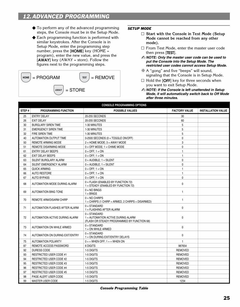
� To perform any of the advanced programmingsteps, the Console must be in the Setup Mode.
� Each programming function is performed withsimilar keystrokes. After the Console is inSetup Mode, enter the programming stepnumber, press the [HOME] key (HOME =program), enter the new value, and press the[AWAY] key (AWAY = store). Follow thefigures next to the programming steps.
SETUP MODEStart with the Console in Test Mode (SetupMode cannot be reached from any othermode).From Test Mode, enter the master user codethen press [TEST].
� NOTE: Only the master user code can be used toput the Console into the Setup Mode. Therestricted user codes cannot access Setup Mode.
� A “gong” and five “beeps” will sound,signaling that the Console is in Setup Mode.Hold the [OFF] key for three seconds whenyou want to exit Setup Mode.
� NOTE: If the Console is left unattended in SetupMode, it will automatically switch back to Off Modeafter three minutes.
CONSOLE PROGRAMMING OPTIONS
STEP # PROGRAMMING FUNCTION POSSIBLE VALUES FACTORY VALUE INSTALLATION VALUE
25 ENTRY DELAY 20-255 SECONDS 3026 EXIT DELAY 20-255 SECONDS 6030 BURGLARY SIREN TIME 1-30 MINUTES 531 EMERGENCY SIREN TIME 1-30 MINUTES 532 FIRE SIREN TIME 1-30 MINUTES 540 AUTOMATION OUTPUT TIME 0-2500 SECONDS (0 = TOGGLE ON/OFF) 050 REMOTE ARMING MODE 2 = HOME MODE; 3 = AWAY MODE 351 REMOTE DISARMING MODE 0 = OFF MODE; 1 = CHIME MODE 061 ENTRY DELAY BEEPS 0 = OFF; 1 = ON 162 EXIT DELAY BEEPS 0 = OFF; 1 = ON 163 SILENT BURGLARY ALARM 0 = AUDIBLE; 1 = SILENT 064 SILENT EMERGENCY ALARM 0 = AUDIBLE; 1 = SILENT 065 QUICK ARMING 0 = OFF; 1 = ON 166 AUTO RESTORE 0 = OFF; 1 = ON 167 AUTO BYPASS 0 = OFF; 1 = ON 0
68 AUTOMATION MODE DURING ALARM0 = FLASH (ENABLED BY FUNCTION 72)1 = STEADY (ENABLED BY FUNCTION 72)
0
69 AUTOMATION BING TONE0 = NO BINGS1 = BINGS
1
70 REMOTE ARM/DISARM CHIRP0 = NO CHIRPS1 = CHIRPS (1 CHIRP = ARMED, 2 CHIRPS = DISARMED)
1
71 AUTOMATION FLASHES AFTER ALARM0 = STANDARD 1 = FLASHING AFTER ALARM
0
72 AUTOMATION ACTIVE DURING ALARM0 = STANDARD1 = AUTOMATION ACTIVE DURING ALARM(FLASH OR STEADY PROGRAMMED BY FUNCTION 68)
0
73 AUTOMATION ON WHILE ARMED0 = STANDARD1 = ON WHILE ARMED
0
74 AUTOMATION ON DURING EXIT/ENTRY0 = STANDARD1 = ON DURING EXIT/ENTRY DELAYS
0
75 AUTOMATION POLARITY 0 = + WHEN OFF; 1 = + WHEN ON 187 REMOTE ACCESS PASSWORD 6 DIGITS 98765492 DURESS CODE 1-5 DIGITS REMOVED93 RESTRICTED USER CODE #1 1-5 DIGITS REMOVED94 RESTRICTED USER CODE #2 1-5 DIGITS REMOVED95 RESTRICTED USER CODE #3 1-5 DIGITS REMOVED96 RESTRICTED USER CODE #4 1-5 DIGITS REMOVED97 RESTRICTED USER CODE #5 1-5 DIGITS REMOVED98 PAGE ALERT USER CODE 1-5 DIGITS REMOVED99 MASTER USER CODE 1-5 DIGITS 1234
Console Programming Table
HOME TEST= PROGRAM = REMOVE
AWAY = STORE
25
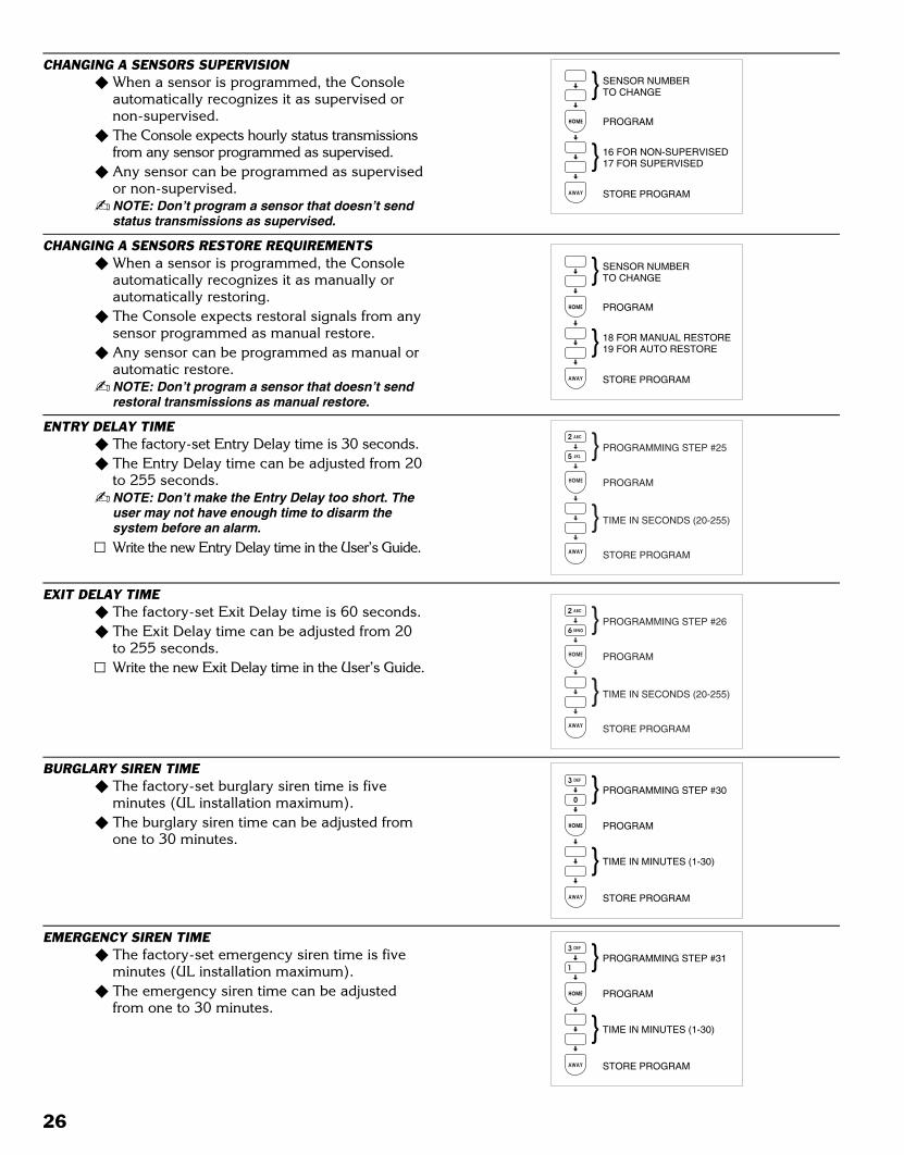
Black 0028
Black0028
CHANGING A SENSORS SUPERVISION� When a sensor is programmed, the Console
automatically recognizes it as supervised ornon-supervised.
� The Console expects hourly status transmissionsfrom any sensor programmed as supervised.
� Any sensor can be programmed as supervisedor non-supervised.
� NOTE: Don’t program a sensor that doesn’t sendstatus transmissions as supervised.
CHANGING A SENSORS RESTORE REQUIREMENTS� When a sensor is programmed, the Console
automatically recognizes it as manually orautomatically restoring.
� The Console expects restoral signals from anysensor programmed as manual restore.
� Any sensor can be programmed as manual orautomatic restore.
� NOTE: Don’t program a sensor that doesn’t sendrestoral transmissions as manual restore.
ENTRY DELAY TIME� The factory-set Entry Delay time is 30 seconds.� The Entry Delay time can be adjusted from 20
to 255 seconds.� NOTE: Don’t make the Entry Delay too short. The
user may not have enough time to disarm thesystem before an alarm.
Write the new Entry Delay time in the User’s Guide.
EXIT DELAY TIME� The factory-set Exit Delay time is 60 seconds.� The Exit Delay time can be adjusted from 20
to 255 seconds.Write the new Exit Delay time in the User’s Guide.
BURGLARY SIREN TIME� The factory-set burglary siren time is five
minutes (UL installation maximum).� The burglary siren time can be adjusted from
one to 30 minutes.
EMERGENCY SIREN TIME� The factory-set emergency siren time is five
minutes (UL installation maximum).� The emergency siren time can be adjusted
from one to 30 minutes.
HOME
AWAY
16 FOR NON-SUPERVISED17 FOR SUPERVISED
SENSOR NUMBERTO CHANGE
PROGRAM
STORE PROGRAM
HOME
AWAY
18 FOR MANUAL RESTORE19 FOR AUTO RESTORE
SENSOR NUMBERTO CHANGE
PROGRAM
STORE PROGRAM
TIME IN SECONDS (20-255)
PROGRAMMING STEP #25
PROGRAM
STORE PROGRAM
TIME IN SECONDS (20-255)
PROGRAMMING STEP #26
PROGRAM
STORE PROGRAM
3 DEF
0
HOME
AWAY
TIME IN MINUTES (1-30)
PROGRAMMING STEP #30
PROGRAM
STORE PROGRAM
3 DEF
1
HOME
AWAY
TIME IN MINUTES (1-30)
PROGRAMMING STEP #31
PROGRAM
STORE PROGRAM
26
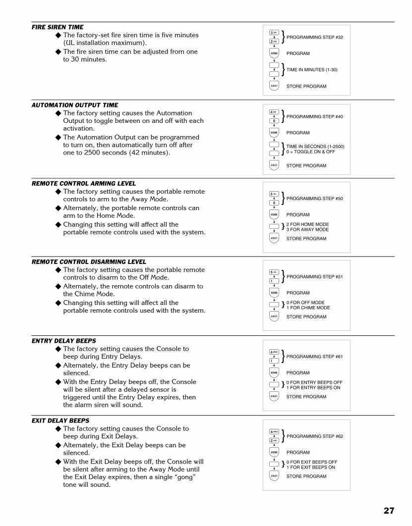
Black 0029
Black0029
FIRE SIREN TIME� The factory-set fire siren time is five minutes
(UL installation maximum).� The fire siren time can be adjusted from one
to 30 minutes.
AUTOMATION OUTPUT TIME� The factory setting causes the Automation
Output to toggle between on and off with eachactivation.
� The Automation Output can be programmedto turn on, then automatically turn off afterone to 2500 seconds (42 minutes).
REMOTE CONTROL ARMING LEVEL� The factory setting causes the portable remote
controls to arm to the Away Mode.� Alternately, the portable remote controls can
arm to the Home Mode.� Changing this setting will affect all the
portable remote controls used with the system.
REMOTE CONTROL DISARMING LEVEL� The factory setting causes the portable remote
controls to disarm to the Off Mode.� Alternately, the remote controls can disarm to
the Chime Mode.� Changing this setting will affect all the
portable remote controls used with the system.
ENTRY DELAY BEEPS� The factory setting causes the Console to
beep during Entry Delays.� Alternately, the Entry Delay beeps can be
silenced.� With the Entry Delay beeps off, the Console
will be silent after a delayed sensor istriggered until the Entry Delay expires, thenthe alarm siren will sound.
EXIT DELAY BEEPS� The factory setting causes the Console to
beep during Exit Delays.� Alternately, the Exit Delay beeps can be
silenced.� With the Exit Delay beeps off, the Console will
be silent after arming to the Away Mode untilthe Exit Delay expires, then a single “gong”tone will sound.
3 DEF
2 ABC
HOME
AWAY
TIME IN MINUTES (1-30)
PROGRAMMING STEP #32
PROGRAM
STORE PROGRAM
4 GHI
0
HOME
AWAY
TIME IN SECONDS (1-2500)0 = TOGGLE ON & OFF
PROGRAMMING STEP #40
PROGRAM
STORE PROGRAM
5 JKL
0
HOME
AWAY
PROGRAMMING STEP #50
PROGRAM
STORE PROGRAM
2 FOR HOME MODE3 FOR AWAY MODE
5 JKL
1
HOME
AWAY
PROGRAMMING STEP #51
PROGRAM
STORE PROGRAM
0 FOR OFF MODE1 FOR CHIME MODE
6 MNO
1
HOME
AWAY
PROGRAMMING STEP #61
PROGRAM
STORE PROGRAM
0 FOR ENTRY BEEPS OFF1 FOR ENTRY BEEPS ON
6 MNO
2 ABC
HOME
AWAY
PROGRAMMING STEP #62
PROGRAM
STORE PROGRAM
0 FOR EXIT BEEPS OFF1 FOR EXIT BEEPS ON
27
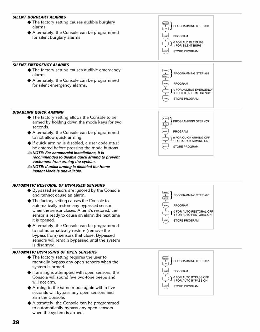
Black 0030
Black0030
SILENT BURGLARY ALARMS� The factory setting causes audible burglary
alarms.� Alternately, the Console can be programmed
for silent burglary alarms.
SILENT EMERGENCY ALARMS� The factory setting causes audible emergency
alarms.� Alternately, the Console can be programmed
for silent emergency alarms.
DISABLING QUICK ARMING� The factory setting allows the Console to be
armed by holding down the mode keys for twoseconds.
� Alternately, the Console can be programmedto not allow quick arming.
� If quick arming is disabled, a user code mustbe entered before pressing the mode buttons.
� NOTE: For commercial installations, it isrecommended to disable quick arming to preventcustomers from arming the system.
� NOTE: If quick arming is disabled the HomeInstant Mode is unavailable.
AUTOMATIC RESTORAL OF BYPASSED SENSORS� Bypassed sensors are ignored by the Console
and cannot cause an alarm.� The factory setting causes the Console to
automatically restore any bypassed sensorwhen the sensor closes. After it’s restored, thesensor is ready to cause an alarm the next timeit is opened.
� Alternately, the Console can be programmedto not automatically restore (remove thebypass from) sensors that close. Bypassedsensors will remain bypassed until the systemis disarmed.
AUTOMATIC BYPASSING OF OPEN SENSORS� The factory setting requires the user to
manually bypass any open sensors when thesystem is armed.
� If arming is attempted with open sensors, theConsole will sound five two-tone beeps andwill not arm.
� Arming to the same mode again within fiveseconds will bypass any open sensors andarm the Console.
� Alternately, the Console can be programmedto automatically bypass any open sensorswhen the system is armed.
6 MNO
3 DEF
HOME
AWAY
PROGRAMMING STEP #63
PROGRAM
STORE PROGRAM
0 FOR AUDIBLE BURG1 FOR SILENT BURG
6 MNO
4 GHI
HOME
AWAY
PROGRAMMING STEP #64
PROGRAM
STORE PROGRAM
0 FOR AUDIBLE EMERGENCY1 FOR SILENT EMERGENCY
6 MNO
5 JKL
HOME
AWAY
PROGRAMMING STEP #65
PROGRAM
STORE PROGRAM
0 FOR QUICK ARMING OFF1 FOR QUICK ARMING ON
6 MNO
6 MNO
HOME
AWAY
PROGRAMMING STEP #66
PROGRAM
STORE PROGRAM
0 FOR AUTO RESTORAL OFF1 FOR AUTO RESTORAL ON
6 MNO
7 PRS
HOME
AWAY
PROGRAMMING STEP #67
PROGRAM
STORE PROGRAM
0 FOR AUTO BYPASS OFF1 FOR AUTO BYPASS ON
28
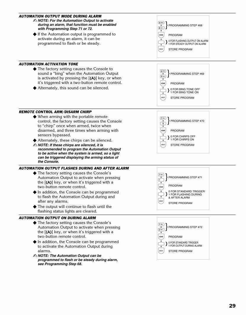
Black 0031
Black0031
AUTOMATION OUTPUT MODE DURING ALARM� NOTE: For the Automation Output to activate
during an alarm, that function must be enabledwith Programming Step 71 or 72.
� If the Automation output is programmed toactivate during an alarm, it can beprogrammed to flash or be steady.
AUTOMATION ACTIVATION TONE� The factory setting causes the Console to
sound a “bing” when the Automation Outputis activated by pressing the [(A)] key, or whenit’s triggered with a two-button remote control.
� Alternately, this sound can be silenced.
REMOTE CONTROL ARM/DISARM CHIRP� When arming with the portable remote
control, the factory setting causes the Consoleto “chirp” once when armed, twice whendisarmed, and three times when arming withsensors bypassed.
� Alternately, these chirps can be silenced.� NOTE: If these chirps are silenced, it is
recommended to program the Automation Outputto be active when the system is armed, so a lightcan be triggered displaying the arming status ofthe Console.
AUTOMATION OUTPUT FLASHES DURING AND AFTER ALARM� The factory setting causes the Console’s
Automation Output to activate when pressingthe [(A)] key, or when it’s triggered with atwo-button remote control.
� In addition, the Console can be programmedto flash the Automation Output during andafter any alarms.
� The output will continue to flash until theflashing status lights are cleared.
AUTOMATION OUTPUT ON DURING ALARM� The factory setting causes the Console’s
Automation Output to activate when pressingthe [(A)] key, or when it’s triggered with atwo-button remote control.
� In addition, the Console can be programmedto activate the Automation Output duringalarms.
� NOTE: The Automation Output can beprogrammed to flash or be steady during alarm,see Programming Step 68.
6 MNO
8 TUV
HOME
AWAY
PROGRAMMING STEP #68
PROGRAM
STORE PROGRAM
0 FOR FLASHING OUTPUT ON ALARM1 FOR STEADY OUTPUT ON ALARM
6 MNO
9 WXY
HOME
AWAY
PROGRAMMING STEP #69
PROGRAM
STORE PROGRAM
0 FOR BING TONE OFF1 FOR BING TONE ON
7 PRS
0
HOME
AWAY
PROGRAMMING STEP #70
PROGRAM
STORE PROGRAM
0 FOR CHIRPS OFF1 FOR CHIRPS ON
7 PRS
1
HOME
AWAY
PROGRAMMING STEP #71
PROGRAM
STORE PROGRAM
0 FOR STANDARD TRIGGER1 FOR FLASHING DURING& AFTER ALARM
7 PRS
2 ABC
HOME
AWAY
PROGRAMMING STEP #72
PROGRAM
STORE PROGRAM
0 FOR STANDARD TRIGGER1 FOR OUTPUT DURING ALARM
29
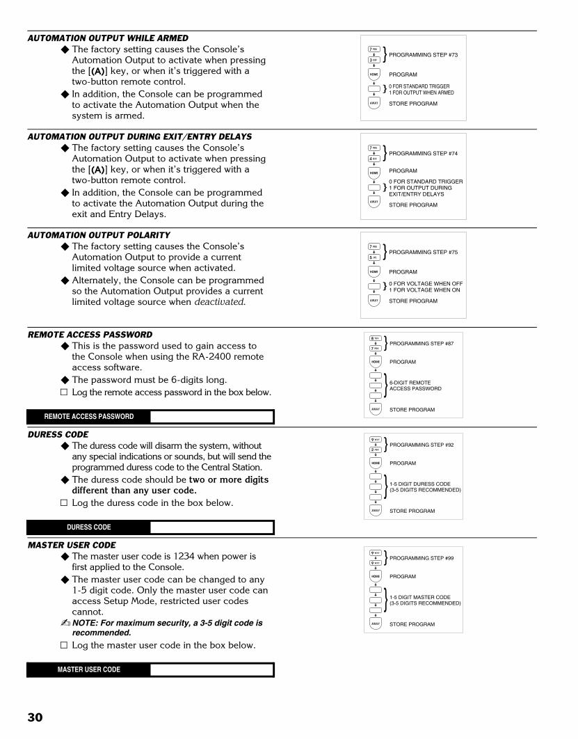
Black 0032
Black0032
AUTOMATION OUTPUT WHILE ARMED� The factory setting causes the Console’s
Automation Output to activate when pressingthe [(A)] key, or when it’s triggered with atwo-button remote control.
� In addition, the Console can be programmedto activate the Automation Output when thesystem is armed.
AUTOMATION OUTPUT DURING EXIT/ENTRY DELAYS� The factory setting causes the Console’s
Automation Output to activate when pressingthe [(A)] key, or when it’s triggered with atwo-button remote control.
� In addition, the Console can be programmedto activate the Automation Output during theexit and Entry Delays.
AUTOMATION OUTPUT POLARITY� The factory setting causes the Console’s
Automation Output to provide a currentlimited voltage source when activated.
� Alternately, the Console can be programmedso the Automation Output provides a currentlimited voltage source when deactivated.
REMOTE ACCESS PASSWORD� This is the password used to gain access to
the Console when using the RA-2400 remoteaccess software.
� The password must be 6-digits long.Log the remote access password in the box below.
REMOTE ACCESS PASSWORD
DURESS CODE� The duress code will disarm the system, without
any special indications or sounds, but will send theprogrammed duress code to the Central Station.
� The duress code should be two or more digitsdifferent than any user code.Log the duress code in the box below.
DURESS CODE
MASTER USER CODE� The master user code is 1234 when power is
first applied to the Console.� The master user code can be changed to any
1-5 digit code. Only the master user code canaccess Setup Mode, restricted user codescannot.
� NOTE: For maximum security, a 3-5 digit code isrecommended.
Log the master user code in the box below.
MASTER USER CODE
7 PRS
3 DEF
HOME
AWAY
PROGRAMMING STEP #73
PROGRAM
STORE PROGRAM
0 FOR STANDARD TRIGGER1 FOR OUTPUT WHEN ARMED
7 PRS
4 GHI
HOME
AWAY
PROGRAMMING STEP #74
PROGRAM
STORE PROGRAM
0 FOR STANDARD TRIGGER1 FOR OUTPUT DURINGEXIT/ENTRY DELAYS
7 PRS
5 JKL
HOME
AWAY
PROGRAMMING STEP #75
PROGRAM
STORE PROGRAM
0 FOR VOLTAGE WHEN OFF1 FOR VOLTAGE WHEN ON
8 TUV
7 PRS
HOME
AWAY
PROGRAMMING STEP #87
PROGRAM
STORE PROGRAM
6-DIGIT REMOTEACCESS PASSWORD
9 WXY
9 WXY
HOME
AWAY
PROGRAMMING STEP #99
PROGRAM
STORE PROGRAM
1-5 DIGIT MASTER CODE(3-5 DIGITS RECOMMENDED)
9 WXY
2 ABC
HOME
AWAY
PROGRAMMING STEP #92
PROGRAM
STORE PROGRAM
1-5 DIGIT DURESS CODE(3-5 DIGITS RECOMMENDED)
30
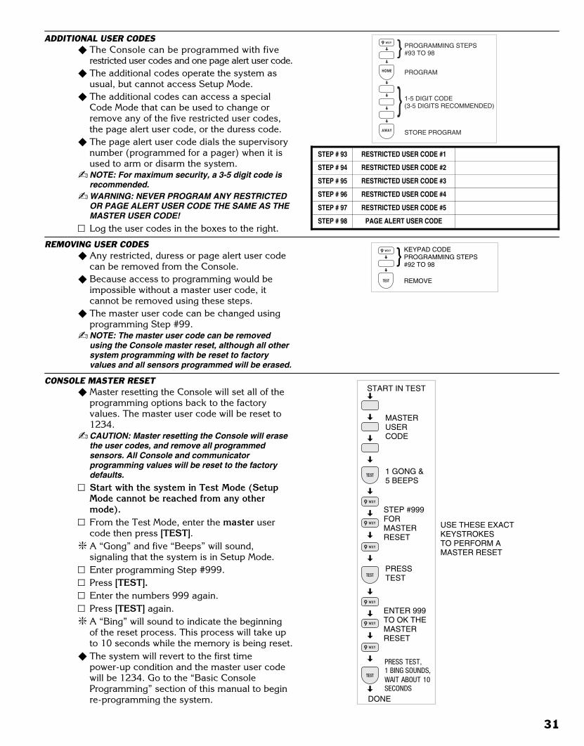
Black 0033
Black0033
ADDITIONAL USER CODES� The Console can be programmed with five
restricted user codes and one page alert user code.� The additional codes operate the system as
usual, but cannot access Setup Mode.� The additional codes can access a special
Code Mode that can be used to change orremove any of the five restricted user codes,the page alert user code, or the duress code.
� The page alert user code dials the supervisorynumber (programmed for a pager) when it isused to arm or disarm the system.
� NOTE: For maximum security, a 3-5 digit code isrecommended.
� WARNING: NEVER PROGRAM ANY RESTRICTEDOR PAGE ALERT USER CODE THE SAME AS THEMASTER USER CODE!
Log the user codes in the boxes to the right.
REMOVING USER CODES� Any restricted, duress or page alert user code
can be removed from the Console.� Because access to programming would be
impossible without a master user code, itcannot be removed using these steps.
� The master user code can be changed usingprogramming Step #99.
� NOTE: The master user code can be removedusing the Console master reset, although all othersystem programming with be reset to factoryvalues and all sensors programmed will be erased.
CONSOLE MASTER RESET� Master resetting the Console will set all of the
programming options back to the factoryvalues. The master user code will be reset to1234.
� CAUTION: Master resetting the Console will erasethe user codes, and remove all programmedsensors. All Console and communicatorprogramming values will be reset to the factorydefaults.
Start with the system in Test Mode (SetupMode cannot be reached from any othermode).From the Test Mode, enter the master usercode then press [TEST].
� A “Gong” and five “Beeps” will sound,signaling that the system is in Setup Mode.Enter programming Step #999.Press [TEST].Enter the numbers 999 again.Press [TEST] again.
� A “Bing” will sound to indicate the beginningof the reset process. This process will take upto 10 seconds while the memory is being reset.
� The system will revert to the first timepower-up condition and the master user codewill be 1234. Go to the “Basic ConsoleProgramming” section of this manual to beginre-programming the system.
PROGRAMMING STEPS#93 TO 98
PROGRAM
STORE PROGRAM
1-5 DIGIT CODE(3-5 DIGITS RECOMMENDED)
9 WXY
TEST
KEYPAD CODEPROGRAMMING STEPS#92 TO 98
REMOVE
STEP # 93 RESTRICTED USER CODE #1
STEP # 94 RESTRICTED USER CODE #2
STEP # 95 RESTRICTED USER CODE #3
STEP # 96 RESTRICTED USER CODE #4
STEP # 97 RESTRICTED USER CODE #5
STEP # 98 PAGE ALERT USER CODE
START IN TEST
MASTERUSERCODE
1 GONG &5 BEEPS
STEP #999FORMASTERRESET
DONE
PRESS TEST,1 BING SOUNDS,WAIT ABOUT 10SECONDS
TEST
9 WXY
9 WXY
TEST
9 WXY
PRESSTEST
9 WXY
9 WXY
TEST
9 WXY
ENTER 999TO OK THEMASTERRESET
USE THESE EXACTKEYSTROKESTO PERFORM AMASTER RESET
31

Black 0034
Black0034
13.COMMUNICATOR PROGRAMMING
SETUP MODE� To perform any of the communicator
programming steps, the Console must be inthe Setup Mode.
� Each programming function is performed withsimilar keystrokes. After the Console is inSetup Mode, enter the programming stepnumber, press the [HOME] key (HOME =program), enter the new value, and press the[AWAY] key (AWAY = store). Follow thefigures next to the programming step. Start with the Console in Test Mode (SetupMode cannot be reached from any othermode).From Test Mode, enter the master user codethen press [TEST].
� NOTE: Only the master user code can be used toput the Console into the Setup Mode. Therestricted user codes cannot access Setup Mode.
� A “gong” and five “beeps” will sound,signaling that the Console is in Setup Mode.Hold the [OFF] key for three seconds whenyou want to exit Setup Mode.
� NOTE: If the Console is left unattended in SetupMode, it will automatically switch back to Off Modeafter three minutes.
GENERAL COMMUNICATOR OPTIONS
STEP # PROGRAMMINGFUNCTION
POSSIBLEVALUES
FACTORYVALUE
INSTALLATIONVALUE
76 2-WAY AUDIO 0 = NONE; 1 = LISTEN; 2 = 2-WAY MANUAL; 3 = 2-WAY FULL DUPLEX 0
78VOICE RESPONSE FROM CONSOLE SPEAKER(AND REMOTE SPEAKER IF USED)
0 = VOICE RESPONSE DISABLED1 = VOICE RESPONSE ENABLED
0
100 REMOTE PROGRAMMING LOCKOUT 0 = UNLOCK; 1 = LOCK 0101 CALL LIMITER 0 = OFF; 1 = FIVE CALLS PER ARMING PERIOD 0103 DIALING DELAY 0 = NO DELAY; 1 = 30 SECOND DELAY 0104 DIALING METHOD 0 = TONE; 1 = PULSE 0107 COMMUNICATOR ENABLE 0 = COMMUNICATOR OFF, 1 = COMMUNICATOR ON 0
General Communicator Programming Table
START IN TEST
MASTERUSERCODE
1 GONG &5 BEEPS
TEST
SETUP MODE
32
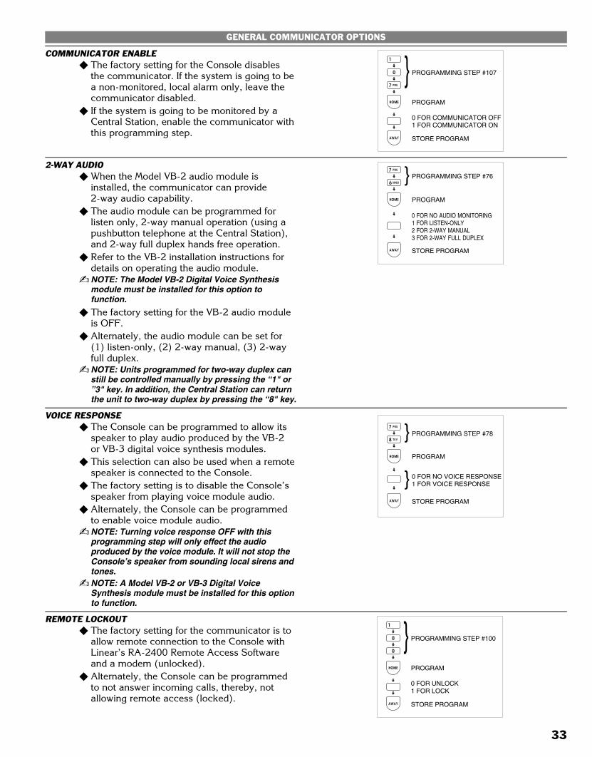
Black 0035
Black0035
GENERAL COMMUNICATOR OPTIONS
COMMUNICATOR ENABLE� The factory setting for the Console disables
the communicator. If the system is going to bea non-monitored, local alarm only, leave thecommunicator disabled.
� If the system is going to be monitored by aCentral Station, enable the communicator withthis programming step.
2-WAY AUDIO� When the Model VB-2 audio module is
installed, the communicator can provide2-way audio capability.
� The audio module can be programmed forlisten only, 2-way manual operation (using apushbutton telephone at the Central Station),and 2-way full duplex hands free operation.
� Refer to the VB-2 installation instructions fordetails on operating the audio module.
� NOTE: The Model VB-2 Digital Voice Synthesismodule must be installed for this option tofunction.
� The factory setting for the VB-2 audio moduleis OFF.
� Alternately, the audio module can be set for(1) listen-only, (2) 2-way manual, (3) 2-wayfull duplex.
� NOTE: Units programmed for two-way duplex canstill be controlled manually by pressing the “1" or”3" key. In addition, the Central Station can returnthe unit to two-way duplex by pressing the “8" key.
VOICE RESPONSE� The Console can be programmed to allow its
speaker to play audio produced by the VB-2or VB-3 digital voice synthesis modules.
� This selection can also be used when a remotespeaker is connected to the Console.
� The factory setting is to disable the Console’sspeaker from playing voice module audio.
� Alternately, the Console can be programmedto enable voice module audio.
� NOTE: Turning voice response OFF with thisprogramming step will only effect the audioproduced by the voice module. It will not stop theConsole’s speaker from sounding local sirens andtones.
� NOTE: A Model VB-2 or VB-3 Digital VoiceSynthesis module must be installed for this optionto function.
REMOTE LOCKOUT� The factory setting for the communicator is to
allow remote connection to the Console withLinear’s RA-2400 Remote Access Softwareand a modem (unlocked).
� Alternately, the Console can be programmedto not answer incoming calls, thereby, notallowing remote access (locked).
0
7 PRS
HOME
AWAY
0 FOR COMMUNICATOR OFF1 FOR COMMUNICATOR ON
PROGRAMMING STEP #107
PROGRAM
STORE PROGRAM
1
7 PRS
6 MNO
HOME
AWAY
0 FOR NO AUDIO MONITORING1 FOR LISTEN-ONLY2 FOR 2-WAY MANUAL3 FOR 2-WAY FULL DUPLEX
PROGRAM
STORE PROGRAM
PROGRAMMING STEP #76
0
0
HOME
AWAY
0 FOR UNLOCK1 FOR LOCK
PROGRAMMING STEP #100
PROGRAM
STORE PROGRAM
1
7 PRS
8 TUV
HOME
AWAY
0 FOR NO VOICE RESPONSE1 FOR VOICE RESPONSE
PROGRAMMING STEP #78
PROGRAM
STORE PROGRAM
33
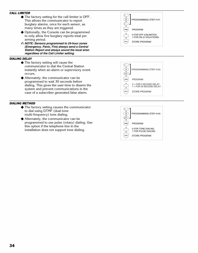
Black 0036
Black0036
CALL LIMITER� The factory setting for the call limiter is OFF.
This allows the communicator to reportburglary alarms, once for each sensor, asmany times as they are triggered.
� Optionally, the Console can be programmedto only allow five burglary reports total perarming period.
� NOTE: Sensors programmed to 24-hour zones(Emergency, Panic, Fire) always send a CentralStation Report and always sound the local sirenregardless of the Call Limiter setting.
DIALING DELAY� The factory setting will cause the
communicator to dial the Central Stationinstantly when an alarm or supervisory eventoccurs.
� Alternately, the communicator can beprogrammed to wait 30 seconds beforedialing. This gives the user time to disarm thesystem and prevent communications in thecase of a subscriber generated false alarm.
DIALING METHOD� The factory setting causes the communicator
to dial using DTMF (dual-tonemulti-frequency) tone dialing.
� Alternately, the communicator can beprogrammed to use pulse (rotary) dialing. Usethis option if the telephone line in theinstallation does not support tone dialing.
0
1
HOME
AWAY
0 FOR OFF (UNLIMITED)1 FOR ON (5 VIOLATIONS)
PROGRAMMING STEP #101
PROGRAM
STORE PROGRAM
1
0 = FOR 0 SECOND DELAY1 = FOR 30 SECOND DELAY
PROGRAMMING STEP #103
PROGRAM
STORE PROGRAM
0
4 GHI
HOME
AWAY
0 FOR TONE DIALING1 FOR PULSE DAILING
PROGRAMMING STEP #104
PROGRAM
STORE PROGRAM
1
34

Black 0037
Black0037
COMMUNICATOR REPORTING OPTIONS
REPORTING FORMAT� The factory setting causes the communicator
to report using the 4 by 2 format. This formatallows four-digit account numbers from 0000to 9999 and provides two-digit alarm codes.
� Alternately ADEMCO CONTACT ID can bechosen as a reporting format. This format allows4-digit account numbers from 0000 to 9999and provides verbose report descriptions withAdemco Contact ID compatible Central Stations.
CALL ROUTING� The factory setting for the communicator is to
route all calls to the primary telephonenumber. If communication is unsuccessfulafter five attempts to the primary number, thesecondary number will be dialed for anadditional five attempts. If the secondarynumber cannot be reached, the communicatorwill “sleep” for five minutes before starting thecall process over again. A total of five sleepcycles (50 call attempts) can occur before thecommunicator stops calling.
� Alternately, the communicator can beprogrammed to report supervisory events (lowbatteries, radio trouble, etc.) to thesupervisory telephone number instead of theprimary or secondary telephone numbers.
� CAUTION: If the page alert user code feature isgoing to be used, the supervisory number isreserved for the pager number. DO NOT SET THECALL ROUTING OPTION TO “1”.
� To disable supervisory reports, set call routingoption to “1” and remove the supervisorytelephone number or in 4 by 2 set the report to “0”.
� NOTE: Do not program the primary and secondarytelephone numbers the same. See the FCCTelephone Rules and Regulations on the rearcover of this manual.
COMMUNICATOR REPORTING OPTIONS
STEP # PROGRAMMINGFUNCTION
POSSIBLEVALUES FACTORY VALUE INSTALLATION
VALUE
86 CALL ROUTING0 = ALL CALLS TO PRIMARY OR SECONDARY NUMBER1 = ALL ALARM CALLS TO PRIMARY OR SECONDARY NUMBER ANDALL OTHERS TO SUPERVISORY NUMBER
0
88 ACCOUNT NUMBER 4 DIGITS EMPTY89 PRIMARY PHONE NUMBER UP TO 20 DIGITS EMPTY90 SECONDARY PHONE NUMBER UP TO 20 DIGITS EMPTY91 SUPERVISORY/ PAGER PHONE NUMBER UP TO 20 DIGITS EMPTY
FOR ALL PHONE NUMBERS ⇒⇒⇒⇒
PRESSING THE (A) KEY INSERTS A 1-SECOND DELAYTHE [FIRE] KEY INSERTS A 5-SECOND DELAYTHE [CHIME] KEY INSERTS A “*”THE (A) KEY INSERTS A “#” IF IT IS THE LAST DIGIT OF THE PHONE NUMBER
105 REPORTING FORMAT 0 = 4 BY 2; 1 = ADEMCO 0108 REPORT CONSOLE TROUBLE 0 = NO; 1 = YES 0110 REPORT FORCE ARMING 0 = NO; 1 = YES 0111 OPEN/CLOSE 0 = NO; 1 = YES; 2 = MASTER PAC ONLY 0113 POINT ID REPORTING FOR 4 BY 2 FORMAT 0 = NO; 1 = YES 1
Communicator Reporting Option Table
0
5 JKL
HOME
AWAY
0 FOR 4 BY 21 FOR ADEMCO CONTACT ID
PROGRAMMING STEP #105
PROGRAM
STORE PROGRAM
1
8 TUV
6 MNO
HOME
AWAY
PROGRAMMING STEP #86
PROGRAM
STORE PROGRAM
0 FOR ALL TO PRIMARY/SECONDARY1 FOR ALARMS ONLY TO PRIMARY/SECONDARY
35

Black 0038
Black0038
ACCOUNT NUMBER� The communicator’s account number entered
must be 4-digits long.� The factory setting for the account number is
0000.� Enter an account number from 0000 to 9999.
PRIMARY TELEPHONE NUMBER� The primary Central Station telephone number
can be up to 20-digits long. � Digits 0-9 can be used.� Delays and special characters can be entered
in the telephone number (see below).
SECONDARY TELEPHONE NUMBER� The secondary Central Station telephone
number can be up to 20-digits long. � Digits 0-9 can be used.� Delays and special characters can be entered
in the telephone number (see below).� NOTE: To remove the secondary telephone
number, program Step # then press [TEST].
SUPERVISORY/PAGER TELEPHONE NUMBER� The supervisory Central Station or pager
telephone number can be up to 20-digits long. � Digits 0-9 can be used.� Delays and special characters can be entered
in the telephone number (see below).� NOTE: To remove the supervisory/pager
telephone number, program Step # then press[TEST].
TELEPHONE NUMBER DELAYS AND SPECIAL CHARACTERS� When creating telephone numbers with
programming Steps 89, 90, & 91, use thefollowing keys to add dialing delays or specialcharacters.
� Press the (A) key to place a 1-second dialingdelay at the start or anywhere in the middle ofthe telephone number.
� Pressing the (A) key as the last digit of thetelephone number will place a pound (#)character at the end of the telephone number.
� Press the [FIRE] key to place a 5-seconddialing delay anywhere in the telephonenumber.
� Press the [CHIME] key to place a star (*)character anywhere in the telephone number.
8 TUV
9 WXY
HOME
AWAY
PROGRAMMING STEP #89
PROGRAM
STORE PROGRAM
ENTER UP TO 20 DIGITSFOR PRIMARY NUMBER
9 WXY
0
HOME
AWAY
PROGRAMMING STEP #90
PROGRAM
STORE PROGRAM
ENTER UP TO 20 DIGITSFOR SECONDARY NUMBER
9 WXY
1
HOME
AWAY
PROGRAMMING STEP #91
PROGRAM
STORE PROGRAM
ENTER UP TO 20 DIGITSFOR SUPERVISORY NUMBER
8 TUV
8 TUV
HOME
AWAY
PROGRAMMING STEP #88
PROGRAM
STORE PROGRAM
4 DIGITACCOUNT NUMBER
ADDS A 1-SECOND DELAY(START OR MIDDLE OF NUMBER)
ADDS A POUND (#) CHARACTER(END OF NUMBER)
ADDS A 5-SECOND DELAY(ANYWHERE IN NUMBER)
ADDS A STAR ( ) CHARACTER(ANYWHERE IN NUMBER)
36
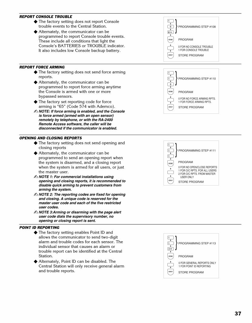
Black 0039
Black0039
REPORT CONSOLE TROUBLE� The factory setting does not report Console
trouble events to the Central Station.� Alternately, the communicator can be
programmed to report Console trouble events.These include all conditions that light theConsole’s BATTERIES or TROUBLE indicator.It also includes low Console backup battery.
REPORT FORCE ARMING� The factory setting does not send force arming
reports.� Alternately, the communicator can be
programmed to report force arming anytimethe Console is armed with one or morebypassed sensors.
� The factory set reporting code for forcearming is “65” (Code 574 with Ademco).
� NOTE: If force arming is enabled, and the Consoleis force armed (armed with an open sensor)remotely by telephone, or with the RA-2400Remote Access software, the caller will bedisconnected if the communicator is enabled.
OPENING AND CLOSING REPORTS� The factory setting does not send opening and
closing reports� Alternately, the communicator can be
programmed to send an opening report whenthe system is disarmed, and a closing reportwhen the system is armed for all users, or justthe master user.
� NOTE 1: For commercial installations usingopening and closing reports, it is recommended todisable quick arming to prevent customers fromarming the system.
� NOTE 2: The reporting codes are fixed for openingand closing. A unique code is reserved for themaster user code and each of the five restricteduser codes.
� NOTE 3:Arming or disarming with the page alertuser code dials the supervisory number, noopening or closing report is sent.
POINT ID REPORTING� The factory setting enables Point ID and
allows the communicator to send two-digitalarm and trouble codes for each sensor. Theindividual sensor that causes an alarm ortrouble report can be identified at the CentralStation.
� Alternately, Point ID can be disabled. TheCentral Station will only receive general alarmand trouble reports.
0 FOR NO CONSOLE TROUBLE1 FOR CONSOLE TROUBLE
PROGRAMMING STEP #108
PROGRAM
STORE PROGRAM
0 FOR NO FORCE ARMING RPTS.1 FOR FORCE ARMING RPTS.
PROGRAMMING STEP #110
PROGRAM
STORE PROGRAM
0 FOR GENERAL REPORTS ONLY1 FOR POINT ID REPORTING
PROGRAMMING STEP #113
PROGRAM
STORE PROGRAM
0 FOR NO OPEN/CLOSE REPORTS1 FOR O/C RPTS. FOR ALL USERS2 FOR O/C RPTS. FROM MASTER USER ONLY
PROGRAMMING STEP #111
PROGRAM
STORE PROGRAM
37
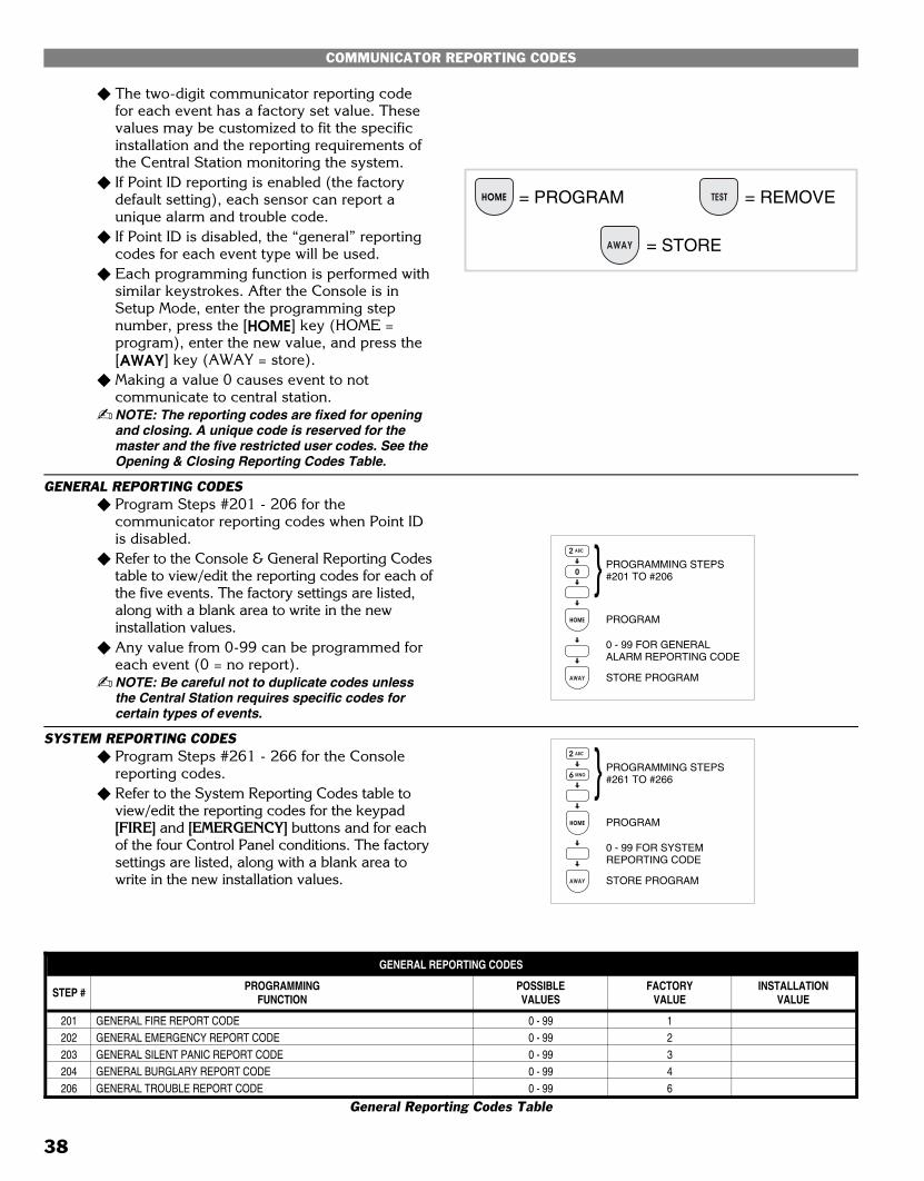
Black 0040
Black0040
COMMUNICATOR REPORTING CODES
� The two-digit communicator reporting codefor each event has a factory set value. Thesevalues may be customized to fit the specificinstallation and the reporting requirements ofthe Central Station monitoring the system.
� If Point ID reporting is enabled (the factorydefault setting), each sensor can report aunique alarm and trouble code.
� If Point ID is disabled, the “general” reportingcodes for each event type will be used.
� Each programming function is performed withsimilar keystrokes. After the Console is inSetup Mode, enter the programming stepnumber, press the [HOME] key (HOME =program), enter the new value, and press the[AWAY] key (AWAY = store).
� Making a value 0 causes event to notcommunicate to central station.
� NOTE: The reporting codes are fixed for openingand closing. A unique code is reserved for themaster and the five restricted user codes. See theOpening & Closing Reporting Codes Table.
GENERAL REPORTING CODES� Program Steps #201 - 206 for the
communicator reporting codes when Point IDis disabled.
� Refer to the Console & General Reporting Codestable to view/edit the reporting codes for each ofthe five events. The factory settings are listed,along with a blank area to write in the newinstallation values.
� Any value from 0-99 can be programmed foreach event (0 = no report).
� NOTE: Be careful not to duplicate codes unlessthe Central Station requires specific codes forcertain types of events.
SYSTEM REPORTING CODES� Program Steps #261 - 266 for the Console
reporting codes.� Refer to the System Reporting Codes table to
view/edit the reporting codes for the keypad[FIRE] and [EMERGENCY] buttons and for eachof the four Control Panel conditions. The factorysettings are listed, along with a blank area towrite in the new installation values.
GENERAL REPORTING CODES
STEP # PROGRAMMINGFUNCTION
POSSIBLEVALUES
FACTORYVALUE
INSTALLATIONVALUE
201 GENERAL FIRE REPORT CODE 0 - 99 1202 GENERAL EMERGENCY REPORT CODE 0 - 99 2203 GENERAL SILENT PANIC REPORT CODE 0 - 99 3204 GENERAL BURGLARY REPORT CODE 0 - 99 4206 GENERAL TROUBLE REPORT CODE 0 - 99 6
General Reporting Codes Table
HOME TEST= PROGRAM = REMOVE
AWAY = STORE
0
HOME
AWAY
0 - 99 FOR GENERALALARM REPORTING CODE
PROGRAMMING STEPS#201 TO #206
PROGRAM
STORE PROGRAM
2 ABC
6 MNO
HOME
AWAY
0 - 99 FOR SYSTEMREPORTING CODE
PROGRAMMING STEPS#261 TO #266
PROGRAM
STORE PROGRAM
2 ABC
38
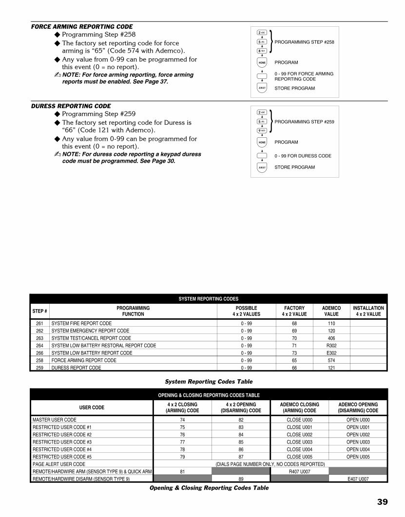
Black 0041
Black0041
FORCE ARMING REPORTING CODE� Programming Step #258� The factory set reporting code for force
arming is “65” (Code 574 with Ademco).� Any value from 0-99 can be programmed for
this event (0 = no report).� NOTE: For force arming reporting, force arming
reports must be enabled. See Page 37.
DURESS REPORTING CODE� Programming Step #259� The factory set reporting code for Duress is
“66” (Code 121 with Ademco).� Any value from 0-99 can be programmed for
this event (0 = no report).� NOTE: For duress code reporting a keypad duress
code must be programmed. See Page 30.
5 JKL
9 WXY
HOME
AWAY
0 - 99 FOR DURESS CODE
PROGRAMMING STEP #259
PROGRAM
STORE PROGRAM
2 ABC
5 JKL
8 TUV
HOME
AWAY
0 - 99 FOR FORCE ARMINGREPORTING CODE
PROGRAMMING STEP #258
PROGRAM
STORE PROGRAM
2 ABC
OPENING & CLOSING REPORTING CODES TABLE
USER CODE 4 x 2 CLOSING(ARMING) CODE
4 x 2 OPENING(DISARMING) CODE
ADEMCO CLOSING(ARMING) CODE
ADEMCO OPENING(DISARMING) CODE
MASTER USER CODE 74 82 CLOSE U000 OPEN U000RESTRICTED USER CODE #1 75 83 CLOSE U001 OPEN U001RESTRICTED USER CODE #2 76 84 CLOSE U002 OPEN U002RESTRICTED USER CODE #3 77 85 CLOSE U003 OPEN U003RESTRICTED USER CODE #4 78 86 CLOSE U004 OPEN U004RESTRICTED USER CODE #5 79 87 CLOSE U005 OPEN U005PAGE ALERT USER CODE (DIALS PAGE NUMBER ONLY, NO CODES REPORTED)REMOTE/HARDWIRE ARM (SENSOR TYPE 9) & QUICK ARM 81 R407 U007REMOTE/HARDWIRE DISARM (SENSOR TYPE 9) 89 E407 U007
Opening & Closing Reporting Codes Table
SYSTEM REPORTING CODES
STEP # PROGRAMMINGFUNCTION
POSSIBLE4 x 2 VALUES
FACTORY4 x 2 VALUE
ADEMCOVALUE
INSTALLATION4 x 2 VALUE
261 SYSTEM FIRE REPORT CODE 0 - 99 68 110262 SYSTEM EMERGENCY REPORT CODE 0 - 99 69 120263 SYSTEM TEST/CANCEL REPORT CODE 0 - 99 70 406264 SYSTEM LOW BATTERY RESTORAL REPORT CODE 0 - 99 71 R302266 SYSTEM LOW BATTERY REPORT CODE 0 - 99 73 E302258 FORCE ARMING REPORT CODE 0 - 99 65 574259 DURESS REPORT CODE 0 - 99 66 121
System Reporting Codes Table
39

Black 0042
Black0042
4 BY 2 FORMAT POINT ID REPORTING CODES
4 BY 2 FORMAT POINT ID ALARM REPORT CODES� Refer to the 4 by 2 Format Point ID Reporting
Code table to view/edit the alarm reportingcodes for each of the 12 sensors. Thecommunicator will send these codes if PointID is enabled and any sensor triggers analarm. The factory settings are listed, alongwith a blank area to write in the newinstallation values.
� NOTE: Be careful not to duplicate codes unlessthe Central Station requires specific codes forcertain types of sensors.
� Each programming function is performed withsimilar keystrokes. After the system is inSetup Mode, enter the programming stepnumber, press the [HOME] key (HOME =program), enter the new value, and press the[AWAY] key (AWAY = store).
4 BY 2 FORMAT POINT ID TROUBLE REPORT CODES� Refer to the 4 by 2 Format Point ID Reporting
Code table to view/edit the trouble reportingcodes for each of the 12 sensors. Thecommunicator will send these codes if PointID is enabled and any sensor has a low batteryor trouble condition. The factory settings arelisted, along with a blank area to write in thenew installation values.
� NOTE: Be careful not to duplicate codes unlessthe Central Station requires specific codes forcertain types of sensors.
� Each programming function is performed withsimilar keystrokes. After the Console is inSetup Mode, enter the programming stepnumber, press the [HOME] key (HOME =program), enter the new value, and press the[AWAY] key (AWAY = store).
0 - 99 FOR SENSORALARM CODE(0 = NO REPORT)
PROGRAMMING STEPS#210 TO #221
PROGRAM
STORE PROGRAM
0 - 99 FOR SENSORTROUBLE CODE(0 = NO REPORT)
PROGRAMING STEPS#234 TO 245
PROGRAM
STORE PROGRAM
DVS12K24.EPS
40

Black 0043
Black0043
POINT ID REPORTING CODES
STEP # PROGRAMMINGFUNCTION
POSSIBLEVALUES
FACTORYVALUE
INSTALLATIONVALUE
210 SENSOR 1 ALARM REPORT CODE 0 - 99 11211 SENSOR 2 ALARM REPORT CODE 0 - 99 12212 SENSOR 3 ALARM REPORT CODE 0 - 99 13213 SENSOR 4 ALARM REPORT CODE 0 - 99 14214 SENSOR 5 ALARM REPORT CODE 0 - 99 15215 SENSOR 6 ALARM REPORT CODE 0 - 99 16216 SENSOR 7 ALARM REPORT CODE 0 - 99 17217 SENSOR 8 ALARM REPORT CODE 0 - 99 18218 SENSOR 9 ALARM REPORT CODE 0 - 99 19219 SENSOR 10 ALARM REPORT CODE 0 - 99 20220 SENSOR 11 ALARM REPORT CODE 0 - 99 21221 SENSOR 12 ALARM REPORT CODE 0 - 99 22234 SENSOR 1 TROUBLE REPORT CODE 0 - 99 41235 SENSOR 2 TROUBLE REPORT CODE 0 - 99 42236 SENSOR 3 TROUBLE REPORT CODE 0 - 99 43237 SENSOR 4 TROUBLE REPORT CODE 0 - 99 44238 SENSOR 5 TROUBLE REPORT CODE 0 - 99 45239 SENSOR 6 TROUBLE REPORT CODE 0 - 99 46240 SENSOR 7 TROUBLE REPORT CODE 0 - 99 47241 SENSOR 8 TROUBLE REPORT CODE 0 - 99 48242 SENSOR 9 TROUBLE REPORT CODE 0 - 99 49243 SENSOR 10 TROUBLE REPORT CODE 0 - 99 50244 SENSOR 11 TROUBLE REPORT CODE 0 - 99 51245 SENSOR 12 TROUBLE REPORT CODE 0 - 99 52
Point ID Reporting Codes Table
41

Black 0044
Black0044
IMPORTANT INFORMATION
LINEAR LIMITED WARRANTYThis Linear product is warranted against defects in material and workmanshipfor twelve (12) months. The Warranty Expiration Date is labeled on theproduct. This warranty extends only to wholesale customers who buydirect from Linear or through Linear’s normal distribution channels. Lineardoes not warrant this product to consumers. Consumers should inquirefrom their selling dealer as to the nature of the dealer’s warranty, if any. Thereare no obligations or liabilities on the part of Linear Corporation forconsequential damages arising out of or in connection with use orperformance of this product or other indirect damages with respect toloss of property, revenue, or profit, or cost of removal, installation, orreinstallation. All implied warranties, including implied warranties formerchantability and implied warranties for fitness, are valid only until WarrantyExpiration Date as labeled on the product. This Linear CorporationWarranty is in lieu of all other warranties express or implied.All products returned for warranty service require a Return ProductAuthorization Number (RPA#). Contact Linear Technical Services at1-800-421-1587 for an RPA# and other important details.
WIRELESS PRODUCT NOTICELinear radio controls provide a reliable communications link and fill animportant need in portable wireless signaling. However, there are somelimitations which must be observed.
� For U.S. installations only: The radios are required to comply with FCCRules and Regulations as Part 15 devices. As such, they have limitedtransmitter power and therefore limited range.
� A receiver cannot respond to more than one transmitted signal at a timeand may be blocked by radio signals that occur on or near theiroperating frequencies, regardless of code settings.
� Changes or modifications to the device may void FCC compliance.� Infrequently used radio links should be tested regularly to protect
against undetected interference or fault.� A general knowledge of radio and its vagaries should be gained prior
to acting as a wholesale distributor or dealer, and these facts shouldbe communicated to the ultimate users.
FCC NOTICEThis equipment generates and uses radio frequency energy and if notinstalled and used properly, that is, in strict accordance with themanufacturer’s instructions, may cause interference to radio and televisionreception. It has been type tested and found to comply with the limits for aClass B computing device in accordance with Part 15 of FCC Rules, whichare designed to provide reasonable protection against such interference in aresidential installation. However, there is no guarantee that interference willnot occur in a particular installation. If this equipment does cause interferenceto radio or television reception, which can be determined by turning theequipment off and on, the user is encouraged to try to correct the interferenceby one or more of the following measures:
� Relocate the Console away from the TV/radio receiver.� Plug the Console into a different wall outlet so that the Console is on a
different branch circuit.� Re-orient the TV/radio antenna.� If necessary, the user should consult the dealer or an experienced
radio/television technician for additional suggestions.
FCC TELEPHONE RULES AND REGULATIONSThe FCC requires that this alarm dialer system not make more than 15repetitive dialing attempts to a single telephone number. There are nolimitations when the calls are made sequentially to two or more alternativenumbers, or when these calls are spaced 10 minutes apart to a single number.The FCC Rules and Regulations do not specify the re-attempt period as thiscan vary for specific applications. When setting this period, take intoconsideration local, interstate, foreign and special network call completioncharacteristics, network processing time, a sufficient number of rings andbusy/don’t answer modes.
FIRE EVACUATION PLANNINGFor systems that include fire protection, UL requires that the followinginformation be available to the users of the system.
� Draw up a floor plan showing two exits for each room.
The following procedures are to be discussed with thefamily:
�Status of bedroom doors.Familiarity with alarm signals.Testing of door during a fire and use of alternate escape route if door
is hot to touch.�Crawling and holding breath.�Escape fast. No stopping for packing. Meet at designated outdoor spot.�Emphasize that no one is to return to a burning house.�Fire department notification from a neighbor’s phone.�Periodic rehearsal is to be conducted.
INDUSTRY CANADA NOTICESNOTICE: The ringer equivalence number (REN) assigned to each terminaldevice provides an indication of the maximum number of terminals allowedto be connected to a telephone interface. The termination on an interface mayconsist of any combination of devices subject only to the requirement that thesum of the ringer equivalence numbers of all the devices does not exceed 5.NOTICE: The Industry Canada label identifies certified equipment. Thiscertification means that the equipment meets certain telecommunicationsnetwork protective, operational and safety requirements. The Departmentdoes not guarantee the equipment will operate to the user’s satisfaction.Before installing this equipment, users should ensure that it is permissible tobe connected to the facilities of the local telecommunications company. Theequipment must also be installed using an acceptable method of connection.The customer should be aware that compliance with the above conditionsmay not prevent degradation of service in some situations.Repairs to certified equipment should be made by an authorized Canadianmaintenance facility designated by the supplier. Any repairs or alterationsmade by the user to this equipment, or equipment malfunctions, may give thetelecommunications company cause to request the user to disconnect theequipment.Users should ensure for their own protection that the electrical groundconnections of the power utility, telephone lines and internal metallic waterpipe system, if present, are connected together. This precaution may beparticularly important in rural areas.CAUTION: Users should not attempt to make such connections themselves,but should contact the appropriate electric inspection authority, or electrician,as appropriate.
Copyright © 2004 Linear Corporation 214419 D