supervisory control and data acquisition (scada) … · figure 12: example of scada server...
TRANSCRIPT
SUPERVISORY CONTROL AND DATA ACQUISITION
(SCADA) SYSTEMSSYSTEM DESIGN, SELECTION
AND INSTALLATION GUIDELINES

Acknowledgement
The development of this guideline was funded through the Sustainable Energy Industry Development Project (SEIDP). The World Bank through Scaling Up Renewable Energy for Low-Income Countries (SREP) and the Small Island Developing States (SIDSDOCK) provided funding to the PPA as the Project Implementation Agency for the SEIDP. The guidelines have been developed by Global Sustainable Energy Solutions with the support of Dr Herbert Wade and reviewed by PPA and SEIAPI Technical Committees.
These guidelines have been developed for The Pacific Power Association (PPA) and the Sustainable Energy Industry Association of the Pacific Islands (SEIAPI).
They represent latest industry BEST PRACTICE for the Design, Selection and Installation of SCADA Systems
© Copyright 2019
While all care has been taken to ensure this guideline is free from omission and error, no responsibility can be taken for the use of this information in the design, selection and installation of any SCADA system.
Table of Contents
1. Introduction – What Is A SCADA System?......................................................................................................................1
1.1. What Does SCADA Do Well? .................................................................................................................................2
1.2. What Does SCADA Not Do Well? .........................................................................................................................2
2. SCADA System Components ..............................................................................................................................................3
2.1 Hardware Components ..............................................................................................................................................3
2.2 Software Components ................................................................................................................................................3
3. What Can You Measure and With What? .......................................................................................................................5
3.1 Field Equipment - Power Analysers .......................................................................................................................5
3.2 Plant Level - Programmable Logic Controllers (PLCs) and Remote Terminal Units (RTUs) .................6
3.3 Field Equipment - Heavy Duty Industrial Sensors .............................................................................................8
4. What Would You Measure In A Small Electrical Grid System With PV Or Other Renewables Connected To It? .............................................................................................................................................9
4.1 Electrical Parameters Of Interest .............................................................................................................................9
5. Communications Links ........................................................................................................................................................ 10
5.1 Optical Fibre Cables Or Fibre Optics ................................................................................................................... 11
5.2 Structured Cabling, Industrial Ethernet and Wi-Fi.......................................................................................... 12
5.3 Serial Cable Links ....................................................................................................................................................... 12
5.3.1 RS 485 Cabling Topology .......................................................................................................................... 13
5.3.2 RS 485 Equipment Connection Detail ................................................................................................... 13
5.4 Serial Radio Links ...................................................................................................................................................... 13
6. SCADA Servers ..................................................................................................................................................................... 14
7. What Should You Be Aware Of If Obtaining A SCADA System For the First Time? ...................................... 15
7.1 Need For A Working Group To Put Together A Specification ..................................................................... 15
7.2 Need To Gather Data On System and Process To Be Controlled .............................................................. 15
7.3 Computer Hardware / Software Considerations ............................................................................................. 17
7.4 Communications Hardware Considerations ..................................................................................................... 17
7.5 Controller and Instrumentation Hardware Considerations ........................................................................... 18
7.6 Field Hardware Considerations............................................................................................................................. 18
7.7 Operator Requirements and Training .................................................................................................................. 19
8. Safety and Security Issues To Consider When Designing & Installing A SCADA System ........................... 20
8.1 Typical Safety Concerns With Remote Control Of Switchgear And Machinery ................................... 20
8.2 Avoiding Incidents Due To Incorrect Inputs ...................................................................................................... 20
8.3 Cyber-Security and It Issues .................................................................................................................................. 21
Table of Figures
Figure 1: Data Flows Between the SCADA Database and Software Server / Client Relationships ...............4
Figure 2: Typical 3 Phase Panel Mounted Power Monitor With Communications Interface .............................6
Figure 3: Typical Programmable Logic Controller CPU Module Showing Status Indication ..............................7
Figure 4: Typical Programmable Logic Controller CPU Module Showing Status Indication LEDs ...................7
Figure 5: Typical Industrial Differential Pressure Transmitter With Heavy Duty Enclosure and Manifold Style Mounting Block. ...........................................................................................................................8
Figure 6: Typical SCADA System For An Island Electrical Network Showing Multiple Renewable Energy Inputs Running In Parallel With Diesel Gensets .............................................................................9
Figure 7: Typical Primary Communications Links For A Medium Sized Island Generation SCADA System ................................................................................................................. 10
Figure 8: EIA 598-A Optical Fibre Identification Colour Code Chart ...................................................................... 11
Figure 9: An Example Of Cat5e UTP Cabling Complete With 8P8c Plug ............................................................ 12
Figure 10: EIA/TIA 485 Or RS 485 Cabling Topology ................................................................................................ 13
Figure 11: EIA/TIA 485 Or RS 485 Wiring Terminations Showing Termination Resistors and Screen Grounding ...................................................................................................................................... 13
Figure 12: Example Of SCADA Server Clustering In Local Hardware Nodes With Access From Remote Central Control Room ............................................................................................................ 14
Abbreviations
A summary of the main acronyms and terms used in this document is listed below:
AC Alternating Current
CAT Category
CCTV Closed-circuit Television
COTS Commercial Off The Shelf
CPU Central Processing Unit
CT Current Transformer
EIA Electronic Industries Alliance
GND Ground
HV High Voltage
HMI Human Machine Interface
Hz Hertz
I/O Input / Output
IP Ingress Protection
ISO International Organisation for Standards
IT Information Technology
LED Light Emitting Diode
LV Low Voltage
MPPT Maximum Power Point Tracker
PC Personal Computer
PLC Programmable Logic Controllers
PV Photovoltaic
ROCOF Rate of Change of Frequency
RS Recommended Standard
RTU Remote Terminal Unit
SCADA Supervisory Control and Data Acquisition
TIA Telecommunications Industry Associations
UPS Uninterruptable Power Supply
USB Universal Serial Bus
VA Volt-Ampere
W Watt

1 | SCADA: Design, Selection and Installation
1. Introduction – What Is A SCADA System?
SCADA is an acronym for Supervisory Control and Data Acquisition. Most industrial control and monitoring systems can be broken down into several levels. Working down the typical organisational chart these are:
• The Managerial or Corporate level – no direct control input but needs data on system performance, uptime/downtime, resource input and product output.
• The Supervisory Control level – typically remote (but occasionally local) control rooms from which high level setpoints are adjusted and overall system monitoring can take place.
• The Plant or Operator level – direct control – packaged generators with onboard controls, equipment run by local operators manually or automatically via local discrete controllers and/or Programmable Logic Controllers (PLCs).
• The Field Equipment or Sensor level – e.g. power meters, temperature sensors, valve actuators, motor starters, circuit breakers etc.
Each control level has specific requirements and working down the levels allows you to “drill down” to individual readings from individual pieces of equipment.
• SCADA is the overall term given to the human machine interface (HMI), tag database, customised applications, underlying software, IT (Information Technology) infrastructure and high level communications network(s) used to provide high level control signals to and acquire operational data from plant level control hardware, fieldbus communications network(s) and smart field devices.
• Many people consider the Plant Control system and communications enabled (or “smart”) Field Equipment (e.g. PLCs) to be an integral part of the SCADA system but for “fail-safe” operation in the event of communications or software failure, plant controls are usually distributed across the network close to their individual generation sources. Plant controls are capable of local operation in an emergency without the coordination and monitoring provided by the SCADA system.
• SCADA can also bridge the gap between live plant data and short, mid or long-term reporting for production staff, management at all levels and even display information to the general public.
A SCADA system provides a higher, more abstracted level of system control than that provided by the individual, plant level, programmable controllers and is particularly suitable for “big picture” monitoring and control of large systems like electricity generation, transmission and distribution networks.
SCADA enables data to be gathered from and supervisory control to be performed for a generation and distribution network or other large-scale industrial process from one or more centralised location(s) rather than having large numbers of individual operators. SCADA can also allow for reports, alarms and general information to be transmitted to personnel with a need to know but no control authority e.g. maintenance staff can be alerted to higher than normal bearing temperatures on a machine and early inspection / repair can be scheduled rather than waiting for a breakdown. This can greatly improve visibility of network assets and usage, whilst simultaneously improving operating efficiencies by automating control systems, allowing remote control of many systems, allowing preventative maintenance actions to reduce the number and severity of breakdowns and speeding diagnosis and rectification of those breakdowns that do occur.
SCADA: Design, Selection and Installation | 2
1.1 What Does SCADA Do Well?
As with any tool, SCADA does some jobs well and others poorly. Understanding the strengths and weaknesses of the technology are key to getting an optimal result from your investment.Some things that a correctly designed and integrated SCADA system does well:
• Provides a Human Machine Interface (HMI) – a simple overview of a complex system for an operator or engineer to interact with.
- For example, on a transmission network screen the operator might see a simplified single line drawing of the entire HV transmission network with power flows indicated and energised feeders / online generators in red, while isolated equipment are in green and faulty equipment flashing yellow.
- Clicking on a substation on the first screen brings up a new screen showing the transformers and switchgear status for that substation. Further screens might show views of individual equipment (e.g. generators, motorised circuit breakers, detailed HV and LV electrical parameters etc).
• Allows for remote monitoring and adjustment of setpoints or triggering a sequence of operations. Adjustment of setpoints usually takes place via the micro-grid controller so that appropriate adjustments to renewable energy curtailment, spinning reserve, battery reserve settings can take place automatically.
• Acquires and stores data from multiple sources at set intervals for comparison against alarm values, display on HMI screens, creating trends vs time or providing reports.
1.2 What Does SCADA Not Do Well?
• Due to the potential for communications delays, direct control of high speed equipment is not recommended. Indeed it is considered very bad practice to use SCADA to directly change the state of a PLC output or similar without going through the internal logic of the PLC program, as this can lead to lockouts being bypassed and result in unexpected and/or unwanted equipment operation.
• Despite often having high-level programming language support (e.g. C++, BASIC or similar), SCADA systems are not designed to be real time operating systems or to ensure correct order of operation in a sequence of events at high speed etc. It is better to deliver setpoints to plant level controllers for real-time control.
• Remote switching applications (e.g. circuit breakers, HV reclosers, contactors etc) are suitable only with the relevant safeguards in place such as local physical isolation points, that cannot be overridden remotely (to ensure safety of maintenance staff). Many sites use CCTV (Closed-circuit Television) to ensure that no personnel are in hazardous areas when allowing an operator to remote control equipment.
3 | SCADA: Design, Selection and Installation
2. SCADA System Components
SCADA systems are comprised of a wide variety of different equipment depending on the customer’s needs, however all share certain key features. Most systems are broken down into sensors, controllers, communications links, a database and various interfaces. There are generally two sets of components - hardware and software.
2.1 Hardware Components
• One or more Human Machine Interface (HMI), Clients, or Operator Stations. These include the relevant display screens, keyboards and other input/output devices to allow the system operator(s) to view and issue commands to the system. It is usually possible to analyse, display, export and/or print-out historical data on a wide variety of system tags for the purposes of fault finding, maximising system efficiency, long term planning etc.
• One or more physical computer servers. These are relatively high specification machines with fast processors, lots of RAM (Random Access Memory) and large capacity hard drives (often in a redundant configuration for reliability).
• Physical instrumentation, sensors, controllers etc to monitor and/or run the plant.
• One or more communications networks to tie the computer servers to the plant instrumentation and controls.
2.2 Software Components
• A SCADA client or HMI package that contains all the background pictures and operator interface information.
• A software database containing information about all the system tags – used to transfer field information to and from the HMI, and for recording historical data.
• Several software programs (usually known as Servers) performing different tasks, typically:
- one or more Input/Output Servers (IOServer) that handle the task of communicating with all the physical devices over the communications network(s).
- an Alarm Server (AlarmServer) that constantly performs comparisons between the measured values of system tags and pre-programmed alarm settings. If a system tag moves outside of the pre-programmed settings, an alarm is triggered - an operator may be notified, or a pre-programmed sequence of events may be undertaken.
- a Report Server (ReportServer) that can generate historical reports using long-term recorded data about certain system tags for later analysis and better understanding of the system operation. E.g. graphing maximum power demand vs time to determine if additional generation resources should be online to meet a peak demand load or looking at the network power factor over time to see if the use of line reactors or a synchronous condenser is recommended for maximum efficiency.
SCADA: Design, Selection and Installation | 4
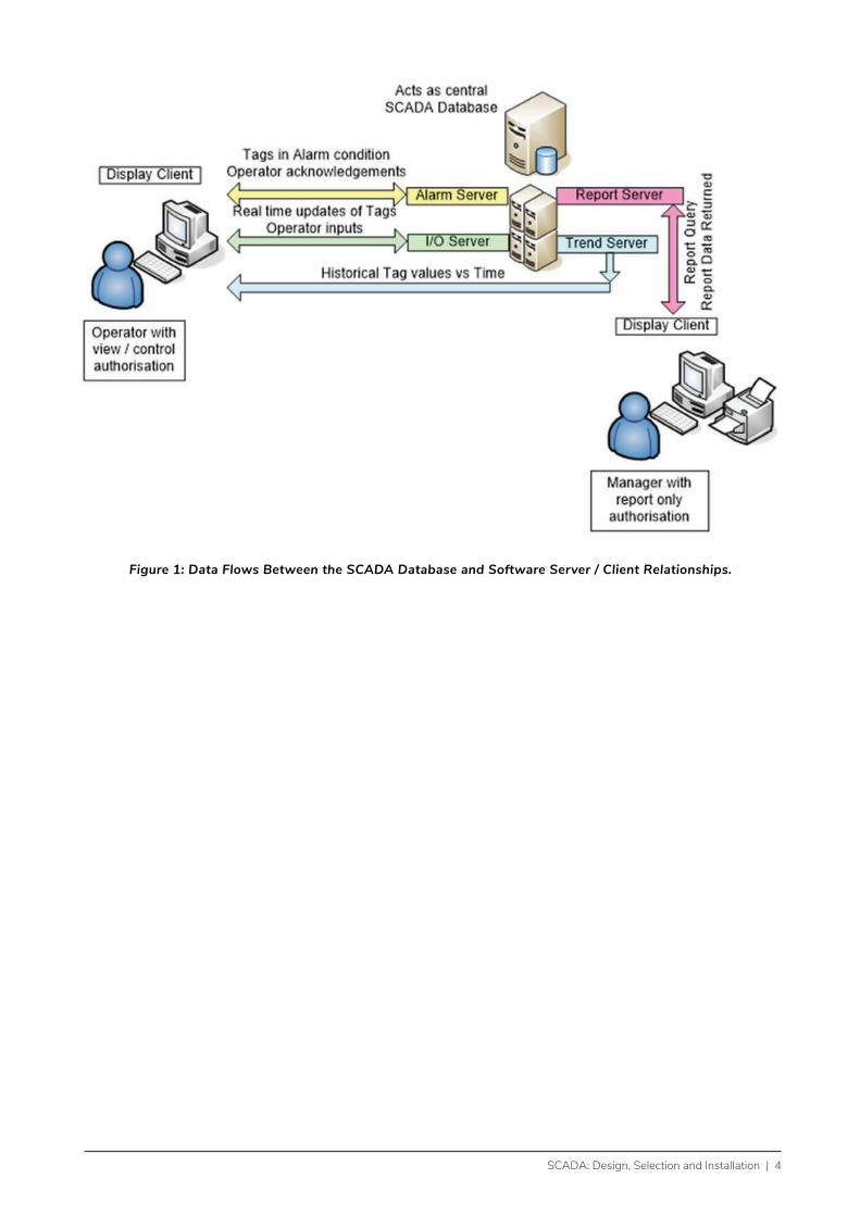
Figure 1: Data Flows Between the SCADA Database and Software Server / Client Relationships.

5 | SCADA: Design, Selection and Installation
3. What Can You Measure and With What?There are many possible network parameters that can be measured and a wide selection of sensors and instrumentation that can be used to capture that information and forward it to the SCADA system. Typical examples include:
• Sensors
• Transducers
• Transmitters
• Data collection devices
3.1 Field Equipment - Power Analysers
Electrical parameters at various points in the network use communications-enabled power analysers. Some typical locations are at the LV AC bus bar(s) in the generation house and the LV AC terminals at transformers around the network (both step up from generation to transmission and step down from transmission to local distribution or large consumers). By monitoring and trending these parameters over time all manner of network issues may be discovered.
Typical electrical parameters measured by a switchboard or transformer mounted power analyser along with CTs (Current Transformers of suitable ratios e.g. 1000A:5A or 200A:5A) and possibly VTs (Voltage Transformers if on HV side say 11kV:415V) include:
• Line to Neutral Voltages, L1-N, L2-N, L3-N
• Line to Line Voltages, L1-L2, L2-L3, L1-L3
• Line Currents, I1, I2, I3
• Neutral Current
• Frequency (Hz)
• Power Factor (PF) – 4 quadrant
• Active Power (W), Reactive Power (VAr), Apparent power (VA)
• Minimum / Maximum Demand values for the above parameters
• Active Energy (kWh), Reactive Energy (kVAr) either import or export
• Total harmonic distortion to say the 15th Harmonic

SCADA: Design, Selection and Installation | 6
Figure 2: Typical 3 Phase Panel Mounted Power Monitor With Communications Interface.
Higher specification power analysers / power quality monitors may also measure and/or record such things as:
• Waveform capture of transient events
• Voltage sags and swells
• Total harmonic distortion to higher levels e.g. the 63rd Harmonic
• Hours run
• Pulse inputs (e.g. from other non-networked equipment with a pulse output like gas meters, water meters and so forth).
3.2 Plant Level - Programmable Logic Controllers (PLCs) and Remote Terminal Units (RTUs)
Programmable Logic Controllers (or PLCs) and Remote Terminal Units (RTUs) are used as field interface devices to link the SCADA system to the plant control level. Traditionally PLCs had relatively high-speed control functionality, lots of digital (relay or transistor based) input and output points and the option for some analog inputs and outputs or multiple communication ports. RTUs on the other hand tended to be specialised for multiple analog or communications inputs and on-board datalogging with minimal control capabilities. In the last decade or so however, the massive reduction in costs for microcontrollers and memory devices has brought about a blurring of the lines between these types of equipment to the point where they are now all but indistinguishable from each other.• Position and status of switchgear (circuit breakers, contactors, thermal overload devices, surge
protection devices, fuses, switches etc).
• These are frequently the local controllers that keep the various plant items running safely regardless of the status of rest of the SCADA system – this might mean running at pre-set values or executing a controlled shutdown in the event of communications loss between remote sites.
7 | SCADA: Design, Selection and Installation
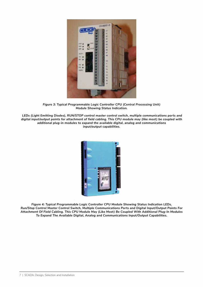
Figure 3: Typical Programmable Logic Controller CPU (Central Processing Unit) Module Showing Status Indication.
LEDs (Light Emitting Diodes), RUN/STOP control master control switch, multiple communications ports and digital input/output points for attachment of field cabling. This CPU module may (like most) be coupled with
additional plug-in modules to expand the available digital, analog and communications input/output capabilities.
Figure 4: Typical Programmable Logic Controller CPU Module Showing Status Indication LEDs, Run/Stop Control Master Control Switch, Multiple Communications Ports and Digital Input/Output Points For Attachment Of Field Cabling. This CPU Module May (Like Most) Be Coupled With Additional Plug-In Modules
To Expand The Available Digital, Analog and Communications Input/Output Capabilities.

SCADA: Design, Selection and Installation | 8
3.3 Field Equipment - Heavy Duty Industrial Sensors
An almost infinite range of measurement functions and sensors for the same are available depending on the utility’s needs:• Flow metering of water, diesel fuel, lubricating oil
• Tank level monitoring
• Temperature of components
• Vibration of components
• Weather conditions (air temperature and humidity, wind speed & direction, rainfall, irradiance, irradiation, cloud cover and direction of movement)
• Direct network interfacing to suitably enabled generator control panels
• CCTV or webcam integration to allow control room operators to view remote sites in real time.
• Indeed, the question must soon change from “what can we monitor” to “what do we need to monitor” otherwise it becomes a case of “what can we afford to monitor” as most SCADA system licencing is based on the quantity of points or tags in the system.
Figure 5: Typical Industrial Differential Pressure Transmitter With Heavy Duty Enclosure and Manifold Style
Mounting Block. Can Be Used For Various Pressure, Flow and Liquid Level Measurements.
9 | SCADA: Design, Selection and Installation
4. What Would You Measure In A Small Electrical Grid System With PV Or Other Renewables Connected To It?
Speedwire Speedwire
Inverters 1 to 24
RS485
RS485
Voltage, Current, Frequencyetc MV and/or HV Point of Interconnection to network
MODBUS TCP/IPOn Ethernet
SMA Cluster Controller
MODBUSTCP/IP
On Ethernet
Circuit breaker status, protection relay contacts,
string fault detection equipment, etc.
Hardwired
600kWp PV Plant PLC
Overall HV NetworkController
SCADA Database On Server
Inverters 1 to 24
Workstation Workstation
Control Room
Corporate Access to Production Reports - no control functions
RS485
RS485
HardwiredStart/Stop
Valve positionMCB’s etc
4-20mAAnalogsignals
HydroTurbine
Dam Level IndicationRiver In Flow
Drinking Water Out Flow Hydro Out Flow River Out Flow
2 MW Genset No.1
2 MW Genset No.2
2 MW Genset No.3
2 MW Genset No.4
2 MW Genset No.5
2 MW Genset No.6
MODBUS RTUOn RS485
RS485 MCB status and control etc. 4-20mA
Diesel TankLevel Indicators
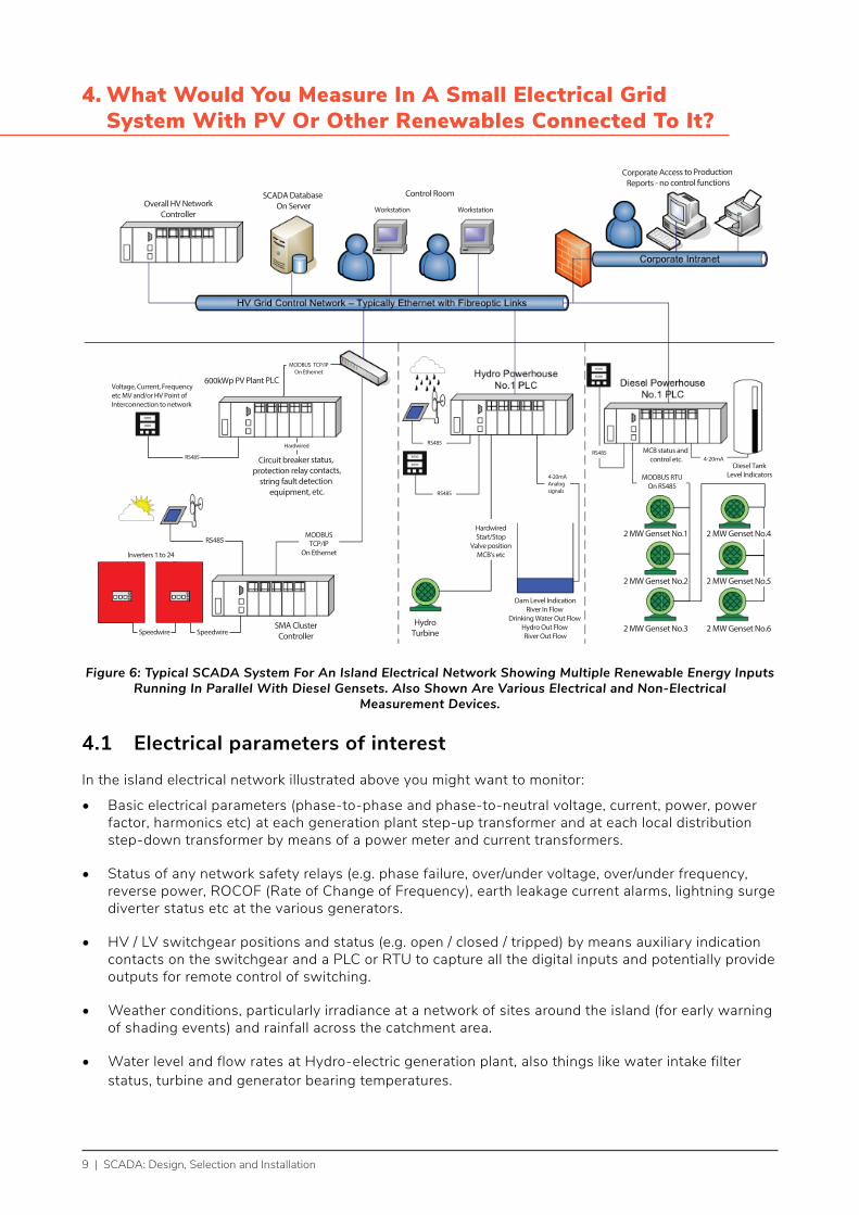
Figure 6: Typical SCADA System For An Island Electrical Network Showing Multiple Renewable Energy Inputs Running In Parallel With Diesel Gensets. Also Shown Are Various Electrical and Non-Electrical
Measurement Devices.
4.1 Electrical parameters of interest
In the island electrical network illustrated above you might want to monitor:
• Basic electrical parameters (phase-to-phase and phase-to-neutral voltage, current, power, power factor, harmonics etc) at each generation plant step-up transformer and at each local distribution step-down transformer by means of a power meter and current transformers.
• Status of any network safety relays (e.g. phase failure, over/under voltage, over/under frequency, reverse power, ROCOF (Rate of Change of Frequency), earth leakage current alarms, lightning surge diverter status etc at the various generators.
• HV / LV switchgear positions and status (e.g. open / closed / tripped) by means auxiliary indication contacts on the switchgear and a PLC or RTU to capture all the digital inputs and potentially provide outputs for remote control of switching.
• Weather conditions, particularly irradiance at a network of sites around the island (for early warning of shading events) and rainfall across the catchment area.
• Water level and flow rates at Hydro-electric generation plant, also things like water intake filter status, turbine and generator bearing temperatures.
SCADA: Design, Selection and Installation | 10
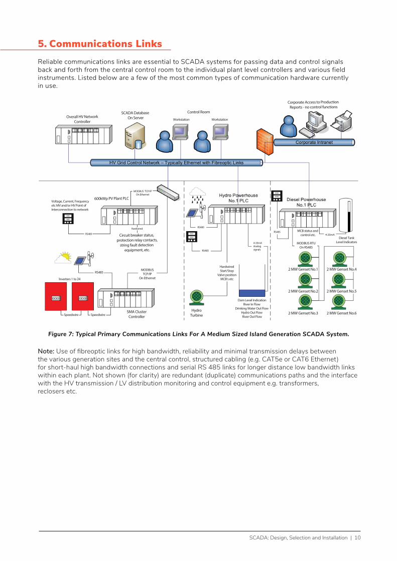
5. Communications Links Reliable communications links are essential to SCADA systems for passing data and control signals back and forth from the central control room to the individual plant level controllers and various field instruments. Listed below are a few of the most common types of communication hardware currently in use.
Speedwire Speedwire
Inverters 1 to 24
RS485
RS485
Voltage, Current, Frequencyetc MV and/or HV Point of Interconnection to network
MODBUS TCP/IPOn Ethernet
SMA Cluster Controller
MODBUSTCP/IP
On Ethernet
Circuit breaker status, protection relay contacts,
string fault detection equipment, etc.
Hardwired
600kWp PV Plant PLC
Overall HV NetworkController
SCADA Database On Server
Inverters 1 to 24
Workstation Workstation
Control Room
Corporate Access to Production Reports - no control functions
RS485
RS485
HardwiredStart/Stop
Valve positionMCB’s etc
4-20mAAnalogsignals
HydroTurbine
Dam Level IndicationRiver In Flow
Drinking Water Out Flow Hydro Out Flow River Out Flow
2 MW Genset No.1
2 MW Genset No.2
2 MW Genset No.3
2 MW Genset No.4
2 MW Genset No.5
2 MW Genset No.6
MODBUS RTUOn RS485
RS485 MCB status and control etc. 4-20mA
Diesel TankLevel Indicators
Figure 7: Typical Primary Communications Links For A Medium Sized Island Generation SCADA System.
Note: Use of fibreoptic links for high bandwidth, reliability and minimal transmission delays between the various generation sites and the central control, structured cabling (e.g. CAT5e or CAT6 Ethernet) for short-haul high bandwidth connections and serial RS 485 links for longer distance low bandwidth links within each plant. Not shown (for clarity) are redundant (duplicate) communications paths and the interface with the HV transmission / LV distribution monitoring and control equipment e.g. transformers, reclosers etc.
11 | SCADA: Design, Selection and Installation
5.1 Optical Fibre Cables Or Fibre Optics
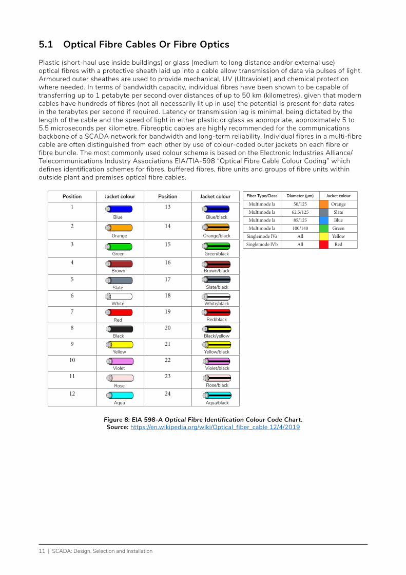
Plastic (short-haul use inside buildings) or glass (medium to long distance and/or external use) optical fibres with a protective sheath laid up into a cable allow transmission of data via pulses of light. Armoured outer sheathes are used to provide mechanical, UV (Ultraviolet ) and chemical protection where needed. In terms of bandwidth capacity, individual fibres have been shown to be capable of transferring up to 1 petabyte per second over distances of up to 50 km (kilometres), given that modern cables have hundreds of fibres (not all necessarily lit up in use) the potential is present for data rates in the terabytes per second if required. Latency or transmission lag is minimal, being dictated by the length of the cable and the speed of light in either plastic or glass as appropriate, approximately 5 to 5.5 microseconds per kilometre. Fibreoptic cables are highly recommended for the communications backbone of a SCADA network for bandwidth and long-term reliability. Individual fibres in a multi-fibre cable are often distinguished from each other by use of colour-coded outer jackets on each fibre or fibre bundle. The most commonly used colour scheme is based on the Electronic Industries Alliance/Telecommunications Industry Associations EIA/TIA-598 “Optical Fibre Cable Colour Coding” which defines identification schemes for fibres, buffered fibres, fibre units and groups of fibre units within outside plant and premises optical fibre cables.
Position Jacket colour Position Jacket colour
1 13
2 14
3 15
4 16
5 17
6 18
7 19
8 20
9 21
10 22
11 23
12 24
Blue
Orange
Green
Brown
Slate
White
Red
Black
Yellow
Violet
Rose
Aqua
Blue/black
Orange/black
Green/black
Brown/black
Slate/black
White/black
Red/black
Black/yellow
Yellow/black
Violet/black
Rose/black
Aqua/black
Fiber Type/Class Diameter (µm) Jacket colour
Multimode la 50/125 OrangeMultimode la 62.5/125 SlateMultimode la 85/125 BlueMultimode la 100/140 Green
Singlemode lVa All YellowSinglemode lVb All Red
Figure 8: EIA 598-A Optical Fibre Identification Colour Code Chart.Source: https://en.wikipedia.org/wiki/Optical_fiber_cable 12/4/2019
SCADA: Design, Selection and Installation | 12
5.2 Structured Cabling, Industrial Ethernet And Wi-Fi
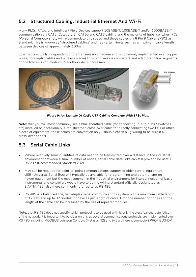
Many PLCs, RTUs, and Intelligent Field Devices support 10BASE-T, 100BASE-T and/or 1000BASE-T communication via CAT5 (Category 5), CAT5e and CAT6 cabling and the majority of hubs, switches, PCs (Personal Computers) etc will accommodate this speed and these cables via 8 Pin 8 Cable (8P8C) as standard. This is known as “structured cabling” and has certain limits such as a maximum cable length between devices of approximately 100m.
Ethernet is actually independent of the transmission medium and is commonly implemented over copper wires, fibre-optic cables and wireless (radio) links with various converters and adaptors to link segments of one transmission medium to another where necessary.
Figure 9: An Example Of Cat5e UTP Cabling Complete With 8P8c Plug.
Note: that you will most commonly see a blue sheathed cable (for connecting PCs to hubs / switches etc) installed or, occasionally, a red sheathed cross-over cable for directly connecting two PCs or other pieces of equipment (these colors are convention only – double check plug wiring to be sure if a cross-over or not).
5.3 Serial Cable Links
• Where relatively small quantities of data need to be transmitted over a distance in the industrial environment between a small number of nodes, serial cable data links can still prove to be useful. RS 232 (Recommended Standard 232)
• May still be required for point-to-point communications support of older control equipment, USB (Universal Serial Bus) will typically be available for programming and data transfer on newer equipment but the most common in the industrial environment for interconnection of basic instruments and controllers would have to be the wiring standard officially designated as EIA/TIA 485, also more commonly referred to as RS 485.
• RS 485 is a balanced line, half-duplex serial communications system with a maximum cable length of 1200m and up to 32 “nodes” or devices per length of cable. Both the number of nodes and the length of the cable can be increased by the use of repeater modules.
Note: that RS 485 does not specify which protocol is to be used with it, only the electrical characteristics of the network. It is important to be clear on this as several communications protocols are implemented over RS 485 including MODBUS, Johnson Controls (Metasys N2) and (via a different connector) PROFIBUS-DP.
13 | SCADA: Design, Selection and Installation
5.3.1 RS 485 Cabling Topology
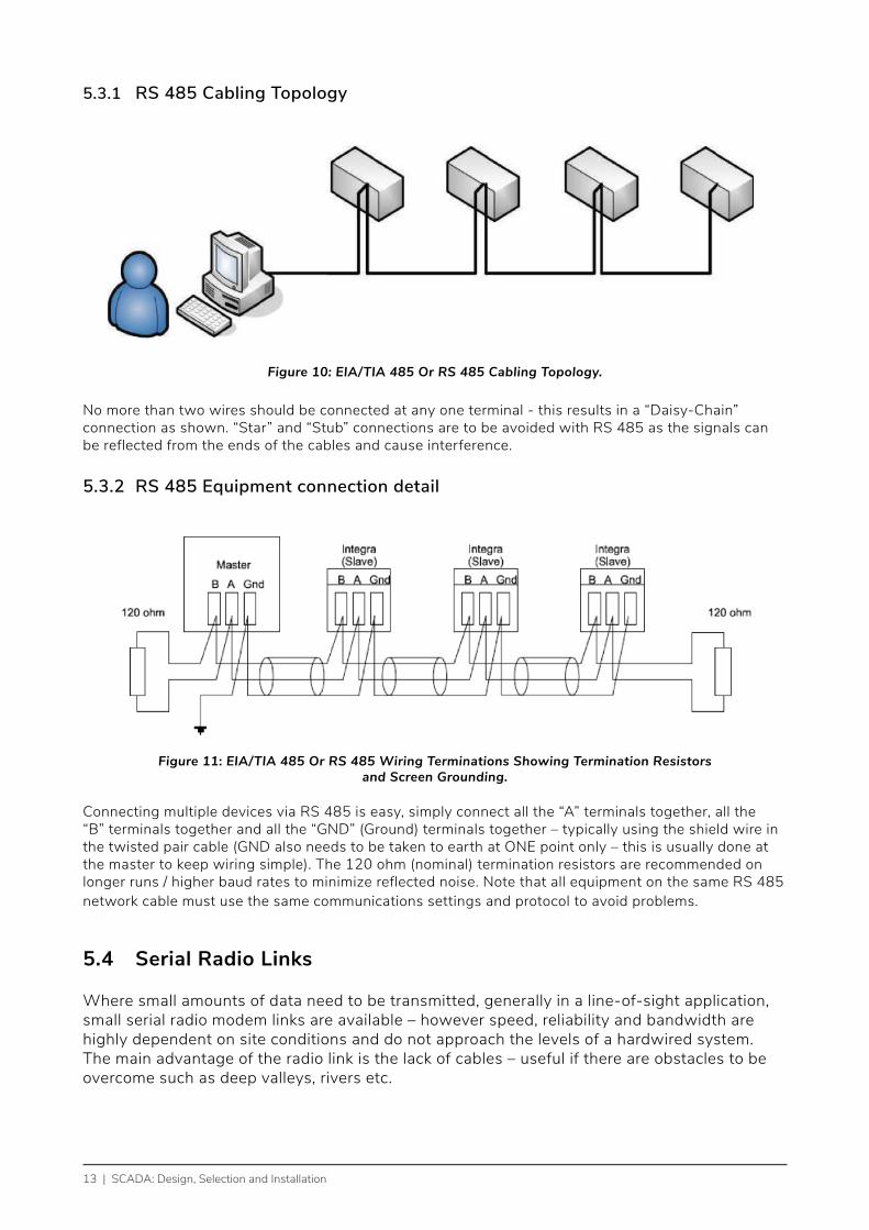
Figure 10: EIA/TIA 485 Or RS 485 Cabling Topology.
No more than two wires should be connected at any one terminal - this results in a “Daisy-Chain” connection as shown. “Star” and “Stub” connections are to be avoided with RS 485 as the signals can be reflected from the ends of the cables and cause interference.
5.3.2 RS 485 Equipment connection detail
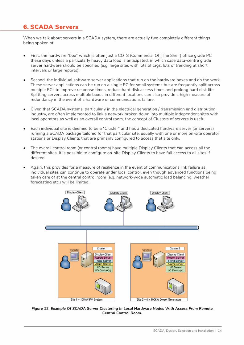
Figure 11: EIA/TIA 485 Or RS 485 Wiring Terminations Showing Termination Resistors and Screen Grounding.
Connecting multiple devices via RS 485 is easy, simply connect all the “A” terminals together, all the “B” terminals together and all the “GND” (Ground) terminals together – typically using the shield wire in the twisted pair cable (GND also needs to be taken to earth at ONE point only – this is usually done at the master to keep wiring simple). The 120 ohm (nominal) termination resistors are recommended on longer runs / higher baud rates to minimize reflected noise. Note that all equipment on the same RS 485 network cable must use the same communications settings and protocol to avoid problems.
5.4 Serial Radio Links
Where small amounts of data need to be transmitted, generally in a line-of-sight application, small serial radio modem links are available – however speed, reliability and bandwidth are highly dependent on site conditions and do not approach the levels of a hardwired system. The main advantage of the radio link is the lack of cables – useful if there are obstacles to be overcome such as deep valleys, rivers etc.
SCADA: Design, Selection and Installation | 14
6. SCADA ServersWhen we talk about servers in a SCADA system, there are actually two completely different things being spoken of.
• First, the hardware “box” which is often just a COTS (Commercial Off The Shelf) office grade PC these days unless a particularly heavy data load is anticipated, in which case data-centre grade server hardware should be specified (e.g. large sites with lots of tags, lots of trending at short intervals or large reports).
• Second, the individual software server applications that run on the hardware boxes and do the work. These server applications can be run on a single PC for small systems but are frequently split across multiple PCs to improve response times, reduce hard disk access times and prolong hard disk life. Splitting servers across multiple boxes in different locations can also provide a high measure of redundancy in the event of a hardware or communications failure.
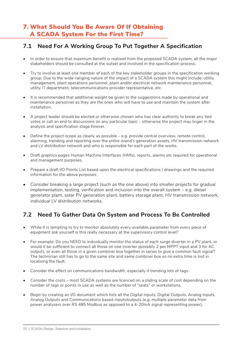
• Given that SCADA systems, particularly in the electrical generation / transmission and distribution industry, are often implemented to link a network broken down into multiple independent sites with local operators as well as an overall control room, the concept of Clusters of servers is useful.
• Each individual site is deemed to be a “Cluster” and has a dedicated hardware server (or servers) running a SCADA package tailored for that particular site, usually with one or more on-site operator stations or Display Clients that are primarily configured to access that site only.
• The overall control room (or control rooms) have multiple Display Clients that can access all the different sites. It is possible to configure on-site Display Clients to have full access to all sites if desired.
• Again, this provides for a measure of resilience in the event of communications link failure as individual sites can continue to operate under local control, even though advanced functions being taken care of at the central control room (e.g. network-wide automatic load balancing, weather forecasting etc.) will be limited.
Figure 12: Example Of SCADA Server Clustering In Local Hardware Nodes With Access From Remote Central Control Room.
15 | SCADA: Design, Selection and Installation
7. What Should You Be Aware Of If Obtaining A SCADA System For the First Time?
7.1 Need For A Working Group To Put Together A Specification
• In order to ensure that maximum benefit is realised from the proposed SCADA system, all the major stakeholders should be consulted at the outset and involved in the specification process.
• Try to involve at least one member of each of the key stakeholder groups in the specification working group. Due to the wide-ranging nature of the impact of a SCADA system this might include; utility management, plant operations personnel, plant and/or electrical network maintenance personnel, utility IT department, telecommunications provider representative, etc.
• It is recommended that additional weight be given to the suggestions made by operational and maintenance personnel as they are the ones who will have to use and maintain the system after installation.
• A project leader should be elected or otherwise chosen who has clear authority to break any tied votes or call an end to discussions on any particular topic – otherwise the project may linger in the analysis and specification stage forever.
• Define the project scope as clearly as possible – e.g. provide central overview, remote control, alarming, trending and reporting over the entire island’s generation assets, HV transmission network and LV distribution network and who is responsible for each part of the works.
• Draft graphics pages Human Machine Interfaces (HMIs), reports, alarms etc required for operational and management purposes.
• Prepare a draft I/O Points List based upon the electrical specifications / drawings and the required information for the above purposes.
• Consider breaking a large project (such as the one above) into smaller projects for gradual implementation, testing, verification and inclusion into the overall system – e.g. diesel generator plant, solar PV generation plant, battery storage plant, HV transmission network, individual LV distribution networks.
7.2 Need To Gather Data On System and Process To Be Controlled
• While it is tempting to try to monitor absolutely every available parameter from every piece of equipment ask yourself is this really necessary at the supervisory control level?
• For example: Do you NEED to individually monitor the status of each surge diverter in a PV plant, or would it be sufficient to connect all those on one inverter (possibly 2 per MPPT input and 3 for AC output), or even all those in a given combiner box together in series to give a common fault signal? The technician still has to go to the same site and same combiner box so no extra time is lost in localising the fault.
• Consider the effect on communications bandwidth, especially if trending lots of tags.
• Consider the costs – most SCADA systems are licenced on a sliding scale of cost depending on the number of tags or points in use as well as the number of “seats” or workstations.
• Begin by creating an I/O document which lists all the Digital inputs, Digital Outputs, Analog Inputs, Analog Outputs and Communications based inputs/outputs (e.g. multiple parameter data from power analysers over RS 485 Modbus as opposed to a 4-20mA signal representing power).
SCADA: Design, Selection and Installation | 16
• Be careful to correctly determine at which control level any given function belongs. Remember, SCADA is not well suited to real-time control, only for monitoring and providing supervisory control (e.g. provision of setpoints).
• Use a dedicated PLC to act as a real-time Network Controller or Micro Grid Controller for the purposes of automatically balancing output from your various generation types in accordance with your load or dispatch schedule and the response rates of your generators. You may also wish to consider automatic load-shedding of non-essential loads in some emergency conditions to avoid a complete systemwide blackout and/or curtailment of excess renewable generation at times of low load in order to keep sufficient spinning reserve online.
• Investigate use of “smart” appliances and inverters / battery storage even at the domestic level to improve grid stability.
• Use a dedicated PLC at each generation plant to act as a real-time controller for that plant based upon setpoints delivered from the Network Controller. If communications are lost this PLC should keep control of the generation system or shut it down safely.Make a list of any / all graphical display screens / HMIs desired and how they link together.
• Work closely with operational and maintenance personnel to ensure all required information is provided in a clear and understandable format.
• Specify the information to be displayed on those screens
• Maintain consistency of information delivery across the SCADA system – e.g. if using GREEN = OPEN or DEENERGISED, RED = CLOSED or ENERGISED and flashing YELLOW = FAULT for the HV switching network screen it would be confusing if the switchgear on the generator screens did not follow the same colour code. In this instance GREEN for generator RUNNING and RED for STOPPED may well be inappropriate and RED for ENERGISED vs GREEN for STANDBY might be a better choice of colour code.
• Consider reporting requirements and statistical analysis e.g. SAIFI (System Average Interruption Frequency Index) and SAIDI (System Average Interruption Duration Index) calculations, network wide status collection for post power outage fault analysis etc

17 | SCADA: Design, Selection and Installation
7.3 Computer Hardware / Software Considerations
• This will largely be dictated by the requirements of the SCADA system.
• Whatever the minimum recommendations of the SCADA system provide (in terms of processor speed, memory capacity, hard drive storage space etc.) should be doubled wherever possible to ensure optimum system performance and to ensure future additions to the SCADA software do not trigger an immediate need for an IT Hardware upgrade.
• Critical machines (e.g. those running SCADA servers) should be enterprise grade – consider dedicated server rooms with rack-mounted servers that allow for enterprise grade features such as dual power supplies, hot swapping of hard drives, redundant hard drives etc.
• Given the distributed nature of most SCADA systems, typical Display Clients or workstations can usually be COTS PCs provided they have the relevant speed and memory capacity.
• As with the control hardware – spares of critical parts e.g. entire PC or rack-mount server, hard drives, memory modules, cooling fans and power supplies should be sourced and kept on hand for immediate use.
• You will need to consider specifying whether redundancy of servers is required and what kind of redundancy you want.
• The choice to split different servers across different machines for performance reasons will generally need to be determined after the specification stage in conjunction with your chosen SCADA integrator / vendor as this is highly dependent upon individual software packages.
• Consider integration with other utility software (e.g. maintenance scheduling, billing etc) but this should be strictly controlled and kept on the corporate side of an operations / corporate firewall to prevent unauthorised access to real-time control systems.
• Selection criteria are basically everything in Section 7 of these guidelines but should be customised for your particular requirements.
7.4 Communications Hardware Considerations
• Consider your bandwidth requirements. If utilising radio links, check with your local Regulator for bandwith (frequency) allocations and/or licencing requirements. If none exist, may need to adopt an international standard allocation of similar services to avoid interference with other broadcast services such as TV, radio, navigation equipment etc.
• Consider the available bandwidth and reliability of the existing infrastructure.
• It may be wise for the utility to consider installing their own communications infrastructure to guarantee availability – e.g. a radio mesh network or separate fibreoptic cable.
• If considering fibreoptic cable links – the potential exists for the utility to leverage existing poles / rights of way / trenches & conduits as well as the option to on-sell some of the excess bandwidth to customers – thus getting into the telecommunications market as a secondary income stream. Just be careful not to sell too much bandwidth and cause slow downs in the response of your control system.
• Consider use of redundant communications paths for critical applications.

SCADA: Design, Selection and Installation | 18
7.5 Controller and Instrumentation Hardware Considerations
• Where possible, harmonise the control systems across the network as part of the SCADA implementation, i.e. use the same make / range / model of PLCs, RTUs, instruments etc. This will bring efficiencies by:
- Use of high-level SCADA programming functions should be minimised wherever possible, keep control at the operational level, not the supervisory level. That said, where these functions are used they should follow consistent programming techniques including clear descriptions of the operation of the function and how it interacts with other parts of the system for user friendliness.
- minimising the SCADA programming changes between sites, for example the addressing used by a Schneider PLC is completely different to that used by an Allen Bradley PLC. If otherwise similar sites were being configured it would make sense to specify the same PLC on each site to keep SCADA addressing as consistent as possible while also:
- providing commonality of parts which will enable spares from one plant to be used in another in an emergency without system modifications,
- improving technician competence and familiarity with the installation, calibration, programming and general maintenance of the control gear, thus reducing the chance of technician errors and leading to reduced downtimes.
- Take advantage of the functionality of SCADA right from the beginning when specifying new plant or equipment – ensure monitoring capabilities and appropriate communications protocols are built in.
7.6 Field Hardware Considerations
• After all of that it would be a shame to have your hard work ruined by the local environment.
• Field equipment should be mounted in appropriate enclosures which provide mechanical and environmental protection against dust, water and vermin e.g. an IP (Ingress Protection) 56 or IP66 metal enclosure.
• Temperature control is worth noting, particularly with pole-mounted equipment or any other enclosure exposed to the sun or containing heat generating equipment. Such enclosures should be suitably shaded or have a ventilated external double-skin construction.
• Enclosure air-conditioning may be required in extreme conditions.
• Don’t forget surge diverters to protect against lightning and mains events.
• Specify battery and/or solar backup for critical control and monitoring equipment so that you don’t lose power in the event of a grid outage. A minimum 15 minute UPS (Uninterruptable Power Supply) is generally sufficient to start standby generators. Don’t forget that this UPS must not only supply the servers and operator interfaces but also the communications network equipment and the field control devices.

19 | SCADA: Design, Selection and Installation
7.7 Operator Requirements and Training
• Operators and site engineers should be closely involved with any outside contractors during the installation, testing and commissioning phases so they are familiar with the location and operation of all equipment.
• Operators will need to have system operation, HMIs, alarms and procedures to deal with alarms explained to them, preferably with training on a simulated system. It is necessary that the grid operator is familiar with all the generation assets and the usual load conditions as they may need to revert to manual control in the event of a major failure in the automatic micro grid controller.
• It is highly recommended that a capacity building requirement be built into the supply contract, where at least one, preferably more, local staff are trained in the actual programming of PLCs, RTUs and the SCADA software. Computer, networking and communications expertise must also be acquired to allow rapid troubleshooting of system problems. This need not take too long, given the easy to use programming interfaces in the manufacturer’s software a basic level of programming competency can be reached by a proficient industrial electrician / technician in just a week or two. This will eliminate the “outside expert is unavailable” problem that so often causes problems for the island nations. Have your own trained staff and provide them with the equipment to practice on for skill retention (e.g. use the hot spare system outlined in section 8.3) and to pass those same skills on to other personnel. The initial costs will rapidly be paid back in savings the first time an issue occurs.
• In an ideal situation, the local programmer(s) would work with the installation contractors during the installation, programming, testing and commissioning phases to maximise their familiarity with the system. Ideal experience for the programmer varies but typically either a Computer and Networking Engineer with some electrical experience or an Electrical engineer with networking and/or industrial control experience are usually best.
SCADA: Design, Selection and Installation | 20
8. Safety and Security Issues To Consider When Designing & Installing A SCADA System
8.1 Typical Safety Concerns With Remote Control Of Switchgear and Machinery
• Operator is usually remote from the equipment being controlled. Need to implement a robust set of safety procedures around equipment access and control to prevent accidents.
• Remote viewing via CCTV or IPTV (Internet Protocol Television) to ensure safe conditions.
• Remote control isolation (with confirmation signal back to control room) for when workers are onsite. Safety can be further enhanced using captive (castellated) key systems where only one key is provided for both the isolation point and the access point and can only be in one place at a time.
• Local / manual safety and shutdown commands must always override any start command from the SCADA system.
• Reliable communications between control room and onsite technicians.
• Clearly defined procedures, for example Switching Permits, will be required for HV switching operations.
8.2 Avoiding Incidents Due To Incorrect Inputs
• Incomplete or inaccurate data leads to incorrect control inputs by the operator. Data entry limits and Fail Safe values can mitigate this.
• This can be avoided by redundant / duplicate monitoring of critical infrastructure.
• Automatic cross-checking between available data sources by the control systems and flagging of inconsistencies for further investigation by technicians will assist with fault finding and diagnosis.
• Automated diagnostic routines to assist in checking equipment operation.
• Clearly defined procedures for handling unusual / inconsistent readings.
21 | SCADA: Design, Selection and Installation
8.3 Cyber-Security and It Issues
• Because the SCADA system is totally reliant on computers operating correctly it is necessary to take strict measures to keep them in operating condition. Wherever possible, complete isolation of the control networks from corporate and/or external networks is preferred to prevent unauthorised off-site access.
• Institute strong password procedures. Disable unused logins, especially those belonging to former employees.
• Train all personnel in basic IT security procedures and the reasons why they are being instituted.
• Minimise and firewall connection points between the control network, supervisory network and the corporate network / internet.
• Keep operating systems, firewalls, anti-virus, anti-malware and SCADA packages patched to latest versions.
• Set dedicated SCADA clients to launch automatically when their PCs are rebooted, password required to exit SCADA client to use other PC functions.
• Ideally avoid having other applications (e.g. word processing, email, etc) on SCADA client PCs.
• Institute regular backup processes.
• Maintain an inventory of critical spare parts, particularly those with an extended lead time to source, both PCs and PLCs / RTUs – preferably “hot spares” in the form of a test system for operators and technicians to practice on with “cold spares” in storage. That way a known working part can be pulled from “hot spares” to replace a broken field device, the “hot spare” is replaced from “cold spares” which is then commissioned and verified on the test system while the broken field device is either repaired and returned to cold spares or a replacement ordered. Parts count can be minimised by using common parts wherever practical e.g. one type of PLC processor, I/O cards etc.
• Document and practice disaster recovery procedures including complete re-installation and commissioning of the SCADA system onto new hardware from original “as-installed” backups.
• Ensure all user names, passwords etc are securely issued, documented and cancelled as appropriate.
• Disable external boot devices such as USB ports, CD drives etc and institute policies against installing additional software.
• There are many international standards regarding security of SCADA and Industrial Control systems, covering both the technical (hardware / software) and organizational aspects, including “ISO 27005:2018 Information technology – Security Techniques – Information security risk management”. A detailed coverage of all of these is beyond the scope of this document however https://www.ncsc.govt.nz/assets/NCSC-Documents/VCSS-CSO-Final-2019-2.pdf provides a good starting point which can be expanded upon during consultation with the proposed SCADA vendor(s).

SCADA: Design, Selection and Installation | 22