supplement 2004 to the north american specification for
TRANSCRIPT
Missouri University of Science and Technology Missouri University of Science and Technology
Scholars' Mine Scholars' Mine
AISI-Specifications for the Design of Cold-Formed Steel Structural Members
Wei-Wen Yu Center for Cold-Formed Steel Structures
01 Jan 2005
Supplement 2004 to the North American Specification for the Supplement 2004 to the North American Specification for the
Design of Cold-Formed Steel Structural Members Design of Cold-Formed Steel Structural Members
American Iron and Steel Institute
Follow this and additional works at: https://scholarsmine.mst.edu/ccfss-aisi-spec
Part of the Structural Engineering Commons
Recommended Citation Recommended Citation American Iron and Steel Institute, "Supplement 2004 to the North American Specification for the Design of Cold-Formed Steel Structural Members" (2005). AISI-Specifications for the Design of Cold-Formed Steel Structural Members. 137. https://scholarsmine.mst.edu/ccfss-aisi-spec/137
This Technical Report is brought to you for free and open access by Scholars' Mine. It has been accepted for inclusion in AISI-Specifications for the Design of Cold-Formed Steel Structural Members by an authorized administrator of Scholars' Mine. This work is protected by U. S. Copyright Law. Unauthorized use including reproduction for redistribution requires the permission of the copyright holder. For more information, please contact [email protected].
ANSI Approved ANS (AISI/COS/NASPEC-SUP04) Supplement 2004 to the North American Specification for the Design of Cold-Formed Steel Structural Members, 2001 Edition
Supplement 2004 to the Commentary on the North American Specification for the Design of Cold-Formed Steel Structural Members, 2001 Edition
Appendix 1, Design of Cold-Formed Steel Structural Members Using Direct Strength Method
Commentary on Appendix 1, Design of Cold-Formed Steel Structural Members Using Direct Strength Method
A I S I S T A N D A R D
Click the title to go to the corresponding
document
American Iron and Steel Institute 1140 Connecticut Avenue, NW Washington, DC 20036 www.steel.org Publication No. SG05-1
American Iron and Steel Institute

AISI/COS/NASPEC-SUP04
Supplement 2004 to the North
American Specification for the
Design of Cold-Formed Steel
Structural Members
2001 EDITION
Approved in Canada by the
Canadian Standards Association
CSA S136-01
Approved in Mexico by CANACERO
CANACERO
The material contained herein has been developed by a joint effort of the American Ironand Steel Institute Committee on Specifications, the Canadian Standards Association Technical Committee on Cold Formed Steel Structural Members (S136), and Camara Nacional de la Industria del Hierro y del Acero (CANACERO) in Mexico. The organizations and theCommittees have made a diligent effort to present accurate, reliable, and useful information on cold-formed steel design. The Committees acknowledge and are grateful for the contributionsof the numerous researchers, engineers, and others who have contributed to the body of knowledge on the subject. Specific references are included in the Supplement to the Commentaryon the Specification.
With anticipated improvements in understanding of the behavior of cold-formed steel and the continuing development of new technology, this material may eventually become dated. It is anticipated that future editions of this specification will update this material as new information becomes available, but this cannot be guaranteed.
The materials set forth herein are for general information only. They are not a substitute for competent professional advice. Application of this information to a specific project should be reviewed by a registered professional engineer. Indeed, in most jurisdictions, such review isrequired by law. Anyone making use of the information set forth herein does so at their ownrisk and assumes any and all resulting liability arising therefrom.
1st Printing – January, 2005
Produced by American Iron and Steel Institute
Copyright American Iron and Steel Institute and Canadian Standards Association 2005

Supplement 2004 to the North American Cold-Formed Steel Specification, 2001 Edition
TABLE OF CONTENTSSUPPLEMENT 2004 TO THE NORTH AMERICAN SPECIFICATION
FOR THE DESIGN OF COLD-FORMED STEELSTRUCTURAL MEMBERS, 2001 EDITION
DECEMBER, 2004CHANGES AND UPDATES IN CHAPTERS A THROUGH G .......................................................................5
A1.1 Scope and Limits of Applicability ........................................................................................... 5A1.2 Terms ........................................................................................................................................... 5A2.1 Applicable Steels........................................................................................................................ 6A2.3 Ductility....................................................................................................................................... 6A2.4 Delivered Minimum Thickness ............................................................................................... 6A4.1.1 ASD Requirements .................................................................................................................... 6A5.1.1 LRFD Requirements .................................................................................................................. 6A6.1.1 LSD Requirements..................................................................................................................... 6A7.2 Strength Increase from Cold Work of Forming..................................................................... 6A9 Referenced Documents ............................................................................................................. 7B2.2 Uniformly Compressed Stiffened Elements with Circular Holes....................................... 7B3.2 Unstiffened Elements and Edge Stiffeners with Stress Gradient........................................ 7B5 Effective Widths of Stiffened Elements with Multiple Intermediate Stiffeners or
Edge Stiffened Elements with Intermediate Stiffeners....................................................... 10B5.2 Edge Stiffened Elements with Intermediate Stiffeners....................................................... 10C3.1.1 Nominal Section Strength [Resistance]................................................................................. 10C3.1.2.1 Lateral-Torsional Buckling Strength [Resistance] of Open Cross Section Members . 11C3.1.5 Strength [Resistance] of Standing Seam Roof Panel Systems............................................ 12C3.3.1 ASD Method............................................................................................................................. 12C3.3.2 LRFD and LSD Methods......................................................................................................... 12C3.4.1 Web Crippling Strength [Resistance] of Webs without Holes .......................................... 12C3.4.2 Web Crippling Strength [Resistance] of C-Section Webs with Holes .............................. 13C3.5 Combined Bending and Web Crippling............................................................................... 13C3.6 Stiffeners.................................................................................................................................... 16C4.5 Built-Up Members ................................................................................................................... 18C4.6 Compression Members Having One Flange Through-Fastened to Deck or Sheathing 18C4.7 Compression of Z-Section Members Having One Flange Fastened to a Standing
Seam Roof ................................................................................................................................. 18C5.2.1 ASD Method............................................................................................................................. 18C5.2.2 LRFD and LSD Methods......................................................................................................... 19C6.2 Compression............................................................................................................................. 19D3.2.1 Anchorage of Bracing for Roof Systems under Gravity Load with Top Flange
Connected to Sheathing .......................................................................................................... 19D3.2.2 Neither Flange Connected to Sheathing............................................................................... 19D4 Wall Studs and Wall Stud Assemblies.................................................................................. 21D5 Floor, Roof or Wall Steel Diaphragm Construction............................................................ 22E2 Welded Connections ............................................................................................................... 23E2.2 Arc Spot Welds......................................................................................................................... 23
December 2004 This document is copyrighted. Any redistribution is prohibited. 3

Supplement 2004 to the North American Cold-Formed Steel Specification, 2001 Edition
E2.2.2 Tension ...................................................................................................................................... 27E4 Screw Connections .................................................................................................................. 27E4.3.3 Shear in Screws ........................................................................................................................ 27E4.4.3 Tension in Screws .................................................................................................................... 28E4.5 Combined Shear and Pull-Over............................................................................................. 28F1.1 Load and Resistance Factor Design and Limit States Design............................................ 30
CHANGES AND UPDATES IN APPENDICES A AND C .......................................................................... 31A2.2 Other Steels............................................................................................................................... 31C3.1.4 Beams Having One Flange Fastened to a Standing Seam Roof System........................... 31C4.7 Compression of Z-Section Members Having One Flange Fastened to a Standing
Seam Roof ................................................................................................................................. 31E2a Welded Connections ............................................................................................................... 32E3a Bolted Connections.................................................................................................................. 33E5.3 Block Shear Rupture................................................................................................................ 33
CHANGES AND UPDATES IN APPENDIX B........................................................................................... 34A2.2.1 Other Structural Quality Steels.............................................................................................. 34A2.4a Delivered Minimum Thickness ............................................................................................. 34A3.1 Specified Loads ........................................................................................................................ 34A3.2 Temperature Effects ................................................................................................................ 34A6.1.2 Load Factors and Load Combinations for LSD ................................................................... 34A9a Reference Documents.............................................................................................................. 37C2.2 Fracture of Net Section............................................................................................................ 37E2a Welded Connections ............................................................................................................... 37E3a Bolted Connections.................................................................................................................. 37E3.4 Shear and Tension in Bolts ..................................................................................................... 37
Appendix 1, Design of Cold-Formed Steel Structural Members Using the Direct StrengthMethod ............................................................................................................................................ 38
4 This document is copyrighted. Any redistribution is prohibited. December 2004
Supplement 2004 to the North American Cold-Formed Steel Specification, 2001 Edition
SUPPLEMENT 2004 TO THE NORTH AMERICAN SPECIFICATIONFOR THE DESIGN OF COLD-FORMED STEEL
STRUCTURAL MEMBERS, 2001 EDITION
DECEMBER, 2004
CHANGES AND UPDATES IN CHAPTERS A THROUGH G
A1.1 Scope and Limits of Applicability
Change the second paragraph (including the bullets) as the follows:
This Specification includes Symbols and Definitions, Chapters A through G, Appendices A through C, and Appendix 1, which shall apply as follows:
Appendix A shall apply only in the United States,
Appendix B shall apply only in Canada,
Appendix C shall apply only in Mexico, and
Appendix 1 provides alternative design provisions for several sections of Chapter C.
In the fourth paragraph, revise the ending of the first sentence to “….Chapters B through G, Appendixes A through C, and Appendix 1of the Specification.”
Add the following under item (b) and below the tables for factors of safety and the resistance factors:
When rational engineering analysis is used to determine the nominalstrength [nominal resistance] for a failure mode [limit state] already providedin this Specification, the factor of safety shall not be less than the applicable
factor of safety ( nor shall exceed the applicable resistance factor ( for the prescribed failure mode [limit state].
A1.2 Terms
Add the following definitions under the “General Terms” on page 34:
Direct Strength Method. An alternative design method detailed in Appendix 1that provides predictions of member strengths [resistances] without the useof effective widths.
Published Specification. Requirements for a steel listed by a manufacturer,processor, producer, purchaser, or other body, which (1) is generallyavailable in the public domain or is available to the public upon request, (2) is established before the steel is ordered, and (3) as a minimum, specifies minimum mechanical properties, chemical composition limits, and, if coated sheet, coating properties.
December 2004 This document is copyrighted. Any redistribution is prohibited. 5

Supplement 2004 to the North American Cold-Formed Steel Specification, 2001 Edition
A2.1 Applicable Steels
Revise the last sentence in the first paragraph of the section to “…for sheetmaterial as SS or, in the case of high-strength low-alloy steels, as HSLAS or HSLAS-F steels.”
Revise the list of ASTM A1003/A1003M as follows:
ASTM A1003/A1003M (ST Grades 50 (340) H, 40 (275) H, 37 (255) H, 33 (230)H), Steel Sheet, Carbon, Metallic- and Nonmetallic-Coated for Cold-Formed Framing Members
Revise the metric value for Grade 60 of ASTM A1008/A1008M from “(450)”to “(410)”.
A2.3 Ductility
On line 10 from the bottom of page 39, change “For w/t E/Fy” to “For w/t
0.067E/Fsy”.
From the bottom of page 39, on lines 1, 3, 6, 7, 8 (two places), 14 and 16, change “Fy” to “Fsy”.
Change “reduced yield point” to “reduced specified minimum yield point”on line 15 from the bottom of page 39.
On line 4 of page 40, change “Yield point” to “Specified minimum yield point”.
A2.4 Delivered Minimum Thickness
Remove the point symbol, .B
A4.1.1 ASD Requirements
Add “and Appendix 1” to the end of both definitions for Rn and .
A5.1.1 LRFD Requirements
Add “and Appendix 1” to the end of both definitions for Rn and .
A6.1.1 LSD Requirements
Add “and Appendix 1” to the end of both definitions for Rn and .
A7.2 Strength Increase from Cold Work of Forming
Revise Eq. A7.2-1 as follows:
Fya = CFyc + (1 - C) Fyf Fuv (Eq. A7.2-1)
6 This document is copyrighted. Any redistribution is prohibited. December 2004
Supplement 2004 to the North American Cold-Formed Steel Specification, 2001 Edition
A9 Referenced Documents
Add the following references and renumber the sequence of the subsequentreferences:
1. American Iron and Steel Institute (AISI), 1140 Connecticut Avenue, NW, Washington, DC 20036:AISI TS-1-02, Rotational-Lateral Stiffness Test Method for Beam-to-Panel
AssembliesAISI TS-6-04, Standard Procedures for Panel and Anchor Structural TestsAISI-TS-8-04, Base Test Method for Purlins Supporting a Standing Seam
Roof System
Change the reference numbering from “1” and “2” to “2” and “3”,respectively.
Add the following ASTM standard before ASTM F436-00:
ASTM E1592-01, Standard Test method for Structural Performance ofSheet Metal Roof and Siding Systems by Uniform Static Air PressureDifference
Add the following new references to the end of the section:
4. U. S. Army Corps of Engineers, CEGS-07416, Guide Specification forMilitary Construction, Structural Standing Seam Metal Roof (SSSMR)System, 1995
5. Factory Mutual, FM 4471, Approval Standard for Class 1 Metal Roofs, 1986
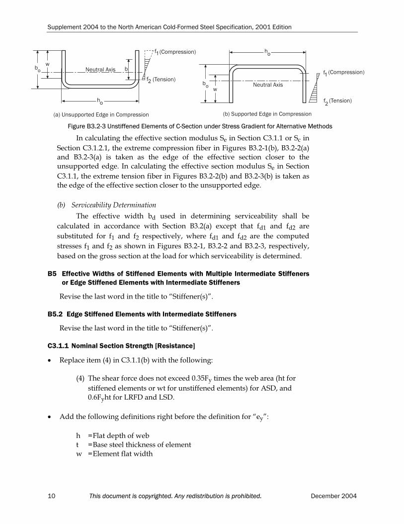
B2.2 Uniformly Compressed Stiffened Elements with Circular Holes
Revise Eq. B2.2-2 as follows:
b =w
)d085.0(
w
)d8.0()22.0(1w hh
when > 0.673 (Eq. B2.2-2)
B3.2 Unstiffened Elements and Edge Stiffeners with Stress Gradient
Replace the whole section as follows:
B3.2 Unstiffened Elements and Edge Stiffeners with Stress Gradient
The following notation is used in this section:
b =Effective width measured from the supported edge, determinedin accordance with Section B2.1(a) with f equal to f1 and with k
and being determined as given in this section f1, f2 =Stresses shown in Figures B3.2-1, B3.2-2, and B3.2-3 calculated on
December 2004 This document is copyrighted. Any redistribution is prohibited. 7

Supplement 2004 to the North American Cold-Formed Steel Specification, 2001 Edition
the basis of the gross section. Where f1 and f2 are both
compression, f1 f2.
= f2/ f1 (absolute value) (Eq. B3.2-1)
=Slenderness factor defined in Section B2.1(a) with f =f1
=Reduction factor defined in this Section or, otherwise, defined in Section B2.1(a)
bo =Overall width of unstiffened element of unstiffened C-section
member as defined in Fig. B3.2-3 ho =Overall depth of unstiffened C-section member as defined in Fig.
B3.2-3
w =Flat width of unstiffened element, where w/t 60
(a) Strength Determination
The effective width, b, of an unstiffened element under stress gradientshall be determined in accordance with Section B2.1(a) with f equal to f1 and
the plate buckling coefficient, k, to be determined by this section unless otherwise noted. For the cases where f1 is in compression and f2 is in tension,
in Section B2.1(a) shall be determined by this section.
(1) When both f1 and f2 are in compression (Fig. B3.2-1):
If the stress decreases toward the unsupported edge (Figure B3.2-1(a)):
34.0
578.0k (Eq. B3.2-2)
If the stress increases toward the unsupported edge (Figure B3.2-1(b)):207.021.057.0k (Eq. B3.2-3)
(2) When f1 is in compression and f2 in tension (Fig. B3.2-2):
(i) If the unsupported edge is in compression (Figure B3.2-2(a)):
=1 when 0.673(1 + )
=
)1(22.01
1 when > 0.673(1 + ) (Eq. B3.2-4)
207.021.057.0k (Eq. B3.2-5)
(ii) If the supported edge is in compression (Fig. B3.2-2(b)):
For <1
=1 when 0.673
=
22.01
1 when > 0.673 (Eq. B3.2-6)
21.17570.1k (Eq. B3.2-7)
For 1
= 1
8 This document is copyrighted. Any redistribution is prohibited. December 2004

Supplement 2004 to the North American Cold-Formed Steel Specification, 2001 Edition
The effective width, b, of the unstiffened elements of an unstiffened C-section member shall be permitted to be determined using the following alternative method:
Alternative 1 for unstiffened C-sections: When the unsupported edge is incompression and the supported edge is in tension (Figure B3.2-3 (a)):
b =w when 0.856 (Eq. B3.2-8)
b = w when > 0.856 (Eq. B3.2-9)
where
= /925.0 (Eq. B3.2-10)
k = 0.145(bo/ho) + 1.256 (Eq. B3.2-11)
0.1 bo/ho 1.0
Alternative 2 for unstiffened C-sections: When the supported edge is in compression and the unsupported edge in tension (Figure B3.2-3(b)), theeffective width is determined in accordance with Section B2.3.
������������ �
������������ �
����������
�� ������������������
�
������������ �
������������ �
����������
�� �������������������
�
Figure B3.2-1 Unstiffened Elements under Stress Gradient, Both Longitudinal Edges in Compression
�� � ���������!��������������
����������
��
�� �"����
���������
�
(b) Supported Edge in Compression
����������
�
� ���������
�������������
�
Figure B3.2-2 Unstiffened Elements under Stress Gradient, One Longitudinal Edgein Compression and the Other Longitudinal Edge in Tension
December 2004 This document is copyrighted. Any redistribution is prohibited. 9
Supplement 2004 to the North American Cold-Formed Steel Specification, 2001 Edition
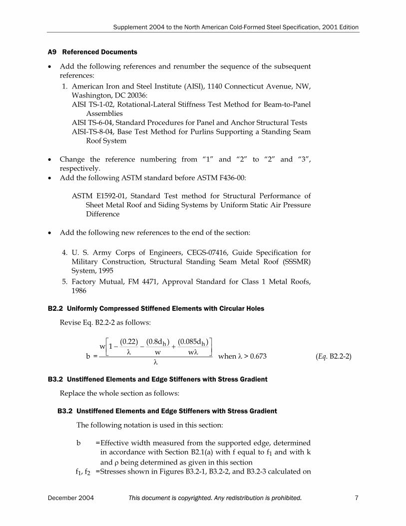
In calculating the effective section modulus Se in Section C3.1.1 or Sc in
Section C3.1.2.1, the extreme compression fiber in Figures B3.2-1(b), B3.2-2(a)and B3.2-3(a) is taken as the edge of the effective section closer to the unsupported edge. In calculating the effective section modulus Se in Section
C3.1.1, the extreme tension fiber in Figures B3.2-2(b) and B3.2-3(b) is taken as the edge of the effective section closer to the unsupported edge.
���
#�
����������
��
�� �"����
���������
�
�� � ���������!�������������� �� �$��������!��������������
�� �
#�
����������
�
��
� �"����
���������
Figure B3.2-3 Unstiffened Elements of C-Section under Stress Gradient for Alternative Methods
(b) Serviceability Determination
The effective width bd used in determining serviceability shall be
calculated in accordance with Section B3.2(a) except that fd1 and fd2 are
substituted for f1 and f2 respectively, where fd1 and fd2 are the computed
stresses f1 and f2 as shown in Figures B3.2-1, B3.2-2 and B3.2-3, respectively,
based on the gross section at the load for which serviceability is determined.
B5 Effective Widths of Stiffened Elements with Multiple Intermediate Stiffeners or Edge Stiffened Elements with Intermediate Stiffeners
Revise the last word in the title to “Stiffener(s)”.
B5.2 Edge Stiffened Elements with Intermediate Stiffeners
Revise the last word in the title to “Stiffener(s)”.
C3.1.1 Nominal Section Strength [Resistance]
Replace item (4) in C3.1.1(b) with the following:
(4) The shear force does not exceed 0.35Fy times the web area (ht for
stiffened elements or wt for unstiffened elements) for ASD, and 0.6Fyht for LRFD and LSD.
Add the following definitions right before the definition for “ey”:
h =Flat depth of web t =Base steel thickness of element w =Element flat width
10 This document is copyrighted. Any redistribution is prohibited. December 2004
Supplement 2004 to the North American Cold-Formed Steel Specification, 2001 Edition
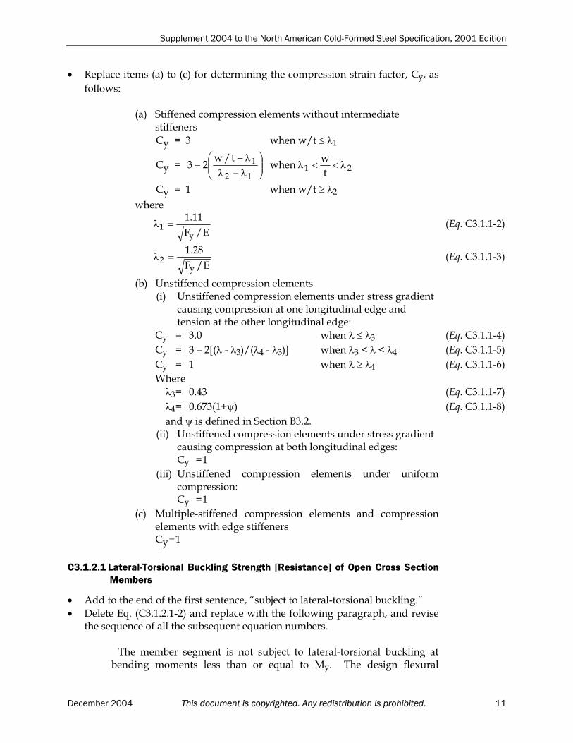
Replace items (a) to (c) for determining the compression strain factor, Cy, as
follows:
(a) Stiffened compression elements without intermediate stiffeners
Cy = 3 when w/t 1
Cy = 2112
1
t
wwhen
t/w23
Cy = 1 when w/t 2
where
E/F
11.1
y1 (Eq. C3.1.1-2)
E/F
28.1
y2 (Eq. C3.1.1-3)
(b) Unstiffened compression elements(i) Unstiffened compression elements under stress gradient
causing compression at one longitudinal edge and tension at the other longitudinal edge:
Cy = 3.0 when 3 (Eq. C3.1.1-4)
Cy = 3 – 2[( - 3)/( 4 - 3)] when 3 < < 4 (Eq. C3.1.1-5)
Cy = 1 when 4 (Eq. C3.1.1-6)
Where
3 = 0.43 (Eq. C3.1.1-7)
4 = 0.673(1+ ) (Eq. C3.1.1-8)
and is defined in Section B3.2. (ii) Unstiffened compression elements under stress gradient
causing compression at both longitudinal edges: Cy = 1
(iii) Unstiffened compression elements under uniformcompression:Cy = 1
(c) Multiple-stiffened compression elements and compression elements with edge stiffenersCy = 1
C3.1.2.1 Lateral-Torsional Buckling Strength [Resistance] of Open Cross Section Members
Add to the end of the first sentence, “subject to lateral-torsional buckling.”
Delete Eq. (C3.1.2.1-2) and replace with the following paragraph, and revisethe sequence of all the subsequent equation numbers.
The member segment is not subject to lateral-torsional buckling atbending moments less than or equal to My. The design flexural
December 2004 This document is copyrighted. Any redistribution is prohibited. 11

Supplement 2004 to the North American Cold-Formed Steel Specification, 2001 Edition
strength [moment resistance] shall be determined in accordance with Section C3.1.1(a).
Change the equation sequence for the remaining equations in this section.
C3.1.5 Strength [Resistance] of Standing Seam Roof Panel Systems
Replace the first paragraph of the section by the followings:
Under gravity loading, the nominal strength [resistance] of standing seam roof panels shall be determined in accordance with Chapters B and C of the Specification or shall be tested in accordance withTS-6, “Standard Procedures for Panel and Anchor Structural Tests” as published by AISI. Under uplift loading, the nominal strength [resistance]of standing seam roof panel systems shall be determined by TS-6. Tests shall be performed according to TS-6 with the following exceptions:
1. The Uplift Pressure Test Procedure for Class 1 Panel Roofs in Factory Mutual Approval Standard 4471 shall be permitted.
2. Existing tests conducted according to the Corps of Engineers CEGS07416 uplift test procedure prior to the adoption of theseprovisions shall be permitted.
The open-open end configuration although not prescribed by the ASTM E1592-01 test procedure shall be permitted provided the end conditions that are tested represent the installed condition and the testshall follow the requirements given in TS-6. All test results shall be evaluated according to this Section.
C3.3.1 ASD Method
Replace Eq. C3.3.1-1 with:
0.1V
V
M
M2
n
v2
nxo
b (Eq. C3.3.1-1)
C3.3.2 LRFD and LSD Methods
Replace Eq. C3.3.2-1 with:
0.1V
V
M
M2
nv
2
nxob
(Eq. C3.3.2-1)
C3.4.1 Web Crippling Strength [Resistance] of Webs without Holes
On page 71, change the ending of the sentence in the fourth paragraph (starting with “One-flange loading…”) as follows “…is equal to or greater than 1.5h.”
12 This document is copyrighted. Any redistribution is prohibited. December 2004
Supplement 2004 to the North American Cold-Formed Steel Specification, 2001 Edition
On the same page, change the ending of the sentence in the fifth paragraph (starting with “Two-flange loading…”) as follows “…is less than 1.5h.”
Change the resistance factor, w, for Canada LSD in Table C3.4.1-4 for the
Unfastened support condition of Interior One-Flange Loading or Reaction from 0.75 to 0.70.
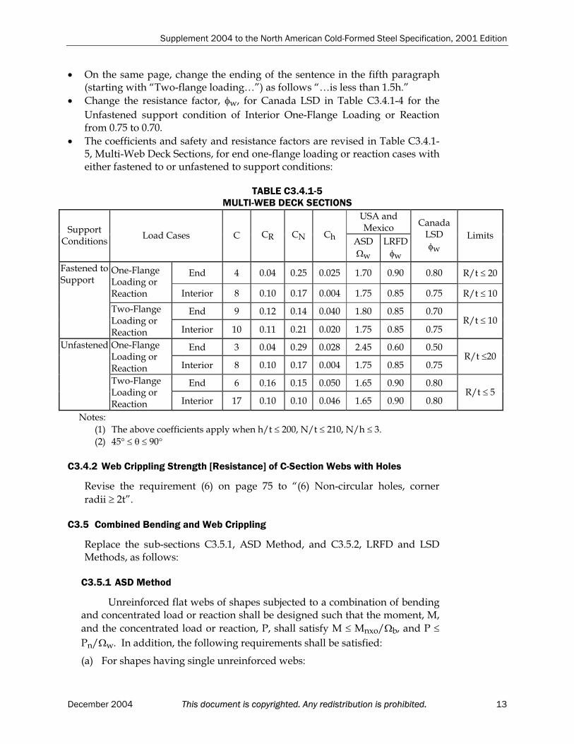
The coefficients and safety and resistance factors are revised in Table C3.4.1-5, Multi-Web Deck Sections, for end one-flange loading or reaction cases witheither fastened to or unfastened to support conditions:
TABLE C3.4.1-5MULTI-WEB DECK SECTIONS
USA and MexicoSupport
ConditionsLoad Cases C CR CN Ch
ASD
w
LRFD
w
CanadaLSD
w
Limits
End 4 0.04 0.25 0.025 1.70 0.90 0.80 R/t 20One-FlangeLoading orReaction Interior 8 0.10 0.17 0.004 1.75 0.85 0.75 R/t 10
End 9 0.12 0.14 0.040 1.80 0.85 0.70
Fastened toSupport
Two-FlangeLoading orReaction Interior 10 0.11 0.21 0.020 1.75 0.85 0.75
R/t 10
End 3 0.04 0.29 0.028 2.45 0.60 0.50One-FlangeLoading orReaction Interior 8 0.10 0.17 0.004 1.75 0.85 0.75
R/t 20
End 6 0.16 0.15 0.050 1.65 0.90 0.80
Unfastened
Two-FlangeLoading orReaction Interior 17 0.10 0.10 0.046 1.65 0.90 0.80
R/t 5
Notes:
(1) The above coefficients apply when h/t 200, N/t 210, N/h 3.
(2) 45 90
C3.4.2 Web Crippling Strength [Resistance] of C-Section Webs with Holes
Revise the requirement (6) on page 75 to “(6) Non-circular holes, corner
radii 2t”.
C3.5 Combined Bending and Web Crippling
Replace the sub-sections C3.5.1, ASD Method, and C3.5.2, LRFD and LSDMethods, as follows:
C3.5.1 ASD Method
Unreinforced flat webs of shapes subjected to a combination of bending and concentrated load or reaction shall be designed such that the moment, M,
and the concentrated load or reaction, P, shall satisfy M Mnxo/ b, and P
Pn/ w. In addition, the following requirements shall be satisfied:
(a) For shapes having single unreinforced webs:
December 2004 This document is copyrighted. Any redistribution is prohibited. 13

Supplement 2004 to the North American Cold-Formed Steel Specification, 2001 Edition
33.1
M
M
P
P91.0
nxon
(Eq. C3.5.1-1)
Exception: At the interior supports of continuous spans, the aboveequation is not applicable to deck or beams with two or more single webs,provided the compression edges of adjacent webs are laterally supported in the negative moment region by continuous or intermittently connected flangeelements, rigid cladding, or lateral bracing, and the spacing between adjacentwebs does not exceed 10 in. (254 mm).
(b) For shapes having multiple unreinforced webs such as I-sections made oftwo C-sections connected back-to-back, or similar sections which providea high degree of restraint against rotation of the web (such as I-sectionsmade by welding two angles to a C-section);
46.1
M
M
P
P88.0
nxon
(Eq. C3.5.1-2)
(c) For the support point of two nested Z-shapes:
65.1
M
M
P
P86.0
nxon
(Eq. C3.5.1-3)
Eq. C3.5.1-3 is valid for shapes that meet the following limits:
h/t 150
N/t 140
Fy 70 ksi (483 MPa or 4920 kg/cm2)
R/t 5.5The following conditions shall also be satisfied: (1) The ends of each section shall be connected to the other section by a
minimum of two 1/2 in. (12.7 mm) diameter A307 bolts through the web.
(2) The combined section shall be connected to the support by a minimum of two 1/2 in. (12.7 mm) diameter A307 bolts through the flanges.
(3) The webs of the two sections shall be in contact. (4) The ratio of the thicker to the thinner part shall not exceed 1.3.
In the above equations:
b =Factor of safety for bending (See Section C3.1.1)
w =Factor of safety for web crippling (See Section C3.4)
=Factor of safety for combined bending and web crippling = 1.70P =Required allowable strength for concentrated load or reaction in
the presence of bending moment Pn =Nominal strength for concentrated load or reaction in absence of
bending moment determined in accordance with Section C3.4 M =Required allowable flexural strength at, or immediately adjacent
to, the point of application of the concentrated load or reaction, P
14 This document is copyrighted. Any redistribution is prohibited. December 2004
Supplement 2004 to the North American Cold-Formed Steel Specification, 2001 Edition
Mnxo=Nominal flexural strength about the centroidal x-axis determined
in accordance with Section C3.1.1
C3.5.2 LRFD and LSD Methods
Unreinforced flat webs of shapes subjected to a combination of bending and concentrated load or reaction shall be designed such that the moment,
,M and the concentrated load or reaction, ,P shall satisfy M bMnxo, and
P wPn. In addition, the following requirements shall be satisfied:
(a) For shapes having single unreinforced webs:
33.1M
M
P
P91.0
nxon
(Eq. C3.5.2-1)
where = 0.90 (LRFD)= 0.75 (LSD)
Exception: At the interior supports of continuous spans, the aboveequation is not applicable to deck or beams with two or more single webs,provided the compression edges of adjacent webs are laterally supported in the negative moment region by continuous or intermittently connected flangeelements, rigid cladding, or lateral bracing, and the spacing between adjacentwebs does not exceed 10 in. (254 mm).
(b) For shapes having multiple unreinforced webs such as I-sections made oftwo C-sections connected back-to-back, or similar sections which providea high degree of restraint against rotation of the web (such as I-sections made by welding two angles to a C-section);
46.1M
M
P
P88.0
nxon
(Eq. C3.5.2-2)
where = 0.90 (LRFD)= 0.75 (LSD)
(c) For two nested Z-shapes
65.1M
M
P
P86.0
nxon
(Eq. C3.5.2-3)
where =0.90 (LRFD) = 0.80 (LSD)
Eq. C3.5.2-3 is valid for shapes that meet the following limits:
h/t 150
N/t 140
Fy 70 ksi (480 MPa or 4910 kg/cm2)
R/t 5.5The following conditions shall also be satisfied: (1) The ends of each section shall be connected to the other section by a
minimum of two 1/2 in. (12.7 mm) diameter A307 bolts through the web.
(2) The combined section shall be connected to the support by a
December 2004 This document is copyrighted. Any redistribution is prohibited. 15

Supplement 2004 to the North American Cold-Formed Steel Specification, 2001 Edition
minimum of two 1/2 in. (12.7 mm) diameter A307 bolts through the flanges.
(3) The webs of the two sections shall be in contact. (4) The ratio of the thicker to the thinner part shall not exceed 1.3.
In the above equations:
b =Resistance factor for bending (See Section C3.1.1)
w =Resistance factor for web crippling (See Section C3.4)
P =Required strength for concentrated load or reaction [factored concentrated load or reaction] in presence of bending moment
P = Pu (LRFD)
P = Pf (LSD)
Pn =Nominal strength [resistance] for concentrated load or reaction
in absence of bending moment determined in accordance withSection C3.4
M =Required flexural strength [factored moment] at, or immediatelyadjacent to, the point of application of the concentrated load or
reaction P
M = Mu (LRFD)
M = Mf (LSD)
Mnxo= Nominal flexural strength [moment resistance] about centroidal
x-axis determined in accordance with Section C3.1.1
C3.6 Stiffeners
Under this section, the title of Section C3.6.1 is changed to “BearingStiffeners”; a new section C3.6.2, Bearing Stiffeners in C-Section FlexuralMembers, is added; and the sequence of subsequent sections is changedaccordingly.
Changes to Section C3.6.1:
Change the title of the Section from “Transverse Stiffeners” to “BearingStiffeners”.
In the first sentence of the first paragraph, change the “Transversestiffeners” to “Bearing stiffeners”.
Revise the definitions for the variables as follows:
Ac =18t2 + As, for bearing stiffener at interior support or under
concentrated load (Eq. C3.6.1-2)Ac =10t2 + As, for bearing stiffener at end support (Eq. C3.6.1-3)
Fwy =Lower value of Fy for beam web, or Fys for stiffener section
Ab =b1t + As, for bearing stiffener at interior support or under
concentrated load (Eq. C3.6.1-4)Ab = b2t + As, for bearing stiffener at end support (Eq. C3.6.1-5)
16 This document is copyrighted. Any redistribution is prohibited. December 2004
Supplement 2004 to the North American Cold-Formed Steel Specification, 2001 Edition
As =Cross sectional area of bearing stiffener
b1 = 25t [0.0024(Lst/t) + 0.72] 25t (Eq. C3.6.1-6)
b2 =12t [0.0044(Lst/t) + 0.83] 12t (Eq. C3.6.1-7)
Lst =Length of bearing stiffener
t =Base steel thickness of beam web
Change “transverse stiffeners” to “the bearing stiffener” on the second line of page 80.
Add Section C3.6.2:
C3.6.2 Bearing Stiffeners in C-Section Flexural Members
For two-flange loading of C-section flexural members with bearingstiffeners that do not meet the requirements of Section C3.6.1, the nominalstrength, Pn, shall be determined as follows:
Pn = 0.7(Pwc + AeFy) Pwc (Eq. C3.6.2-1)
USA and Mexico Canada
(ASD) (LRFD) (LSD)
1.70 0.90 0.80
wherePwc = Web crippling strength [resistance] for C-section flexural member
calculated in accordance with Eq. C3.4.1-1 for single web members, at end or interior locations
Ae =Effective area of bearing stiffener subjected to uniform
compressive stress, calculated at yield point Fy =Yield point of bearing stiffener steel
Eq. C3.6.2-1 applies within the following limits: (1) Full bearing of the stiffener is required. If the bearing width is
narrower than the stiffener such that one of the stiffener flanges is unsupported, Pn shall be reduced by 50%.
(2) Stiffeners shall be C-section stud or track members with a minimumweb depth of 3-1/2 in. (89 mm) and a minimum base steel thicknessof 0.0329 in. (0.84 mm).
(3) The stiffener shall be attached to the flexural member web with at least three fasteners (screws or bolts).
(4) The distance from the flexural member flanges to the first fastener(s)shall not be less than d/8, where d is the overall depth of the flexural member.
(5) The length of the stiffener shall not be less than the depth of the flexural member minus 3/8 in. (9 mm).
(6) The bearing width shall not be less than 1-1/2 in. (38 mm).
December 2004 This document is copyrighted. Any redistribution is prohibited. 17

Supplement 2004 to the North American Cold-Formed Steel Specification, 2001 Edition
Changes in the Current Section C3.6.2
Revise the section number from “C3.6.2” to “C3.6.3” in the title and in all the equation numbers.
Change “transverse stiffeners” in the definition for “a” to “shearstiffeners”.
Changes in the Current Section C3.6.3
Revise the section number from “C3.6.3” to “C3.6.4” in the title.
Revise the sentence to “The design strength [factored resistance] ofmembers with stiffeners that do not meet the requirements of Section C3.6.1, C3.6.2 or C3.6.3, such as stamped or rolled-in stiffeners, shall be determined…”
C4.5 Built-Up Members
Replace item (3) as follows:
(3) The intermediate fastener(s) or weld(s) at any longitudinal member tielocation shall be capable of transmitting a force in any direction of 2.5% ofthe total force in the built-up member (determined in accordance withASD, LRFD or LSD load combinations).
C4.6 Compression Members Having One Flange Through-Fastened to Deck orSheathing
Revise the note on page 85 as follows:
Note:
*Further information on the test procedure should be obtained from AISI TS-
1, “Rotational-Lateral Stiffness Test Methods for Beam-to-Panel Assemblies”,
Part VI of AISI Cold-Formed Steel Design Manual, 2002 edition.
C4.7 Compression of Z-Section Members Having One Flange Fastened to aStanding Seam Roof
Add the following new section:
C4.7 Compression of Z-Section Members Having One Flange Fastened to aStanding Seam Roof
The provisions of this section are applicable only to the United States and Mexico and are given in Section C4.7 of Appendices A and C.
A,C
C5.2.1 ASD Method
On page 87, revise the text of the definition for Pn to “… in accordance with
Sections C4 and C6”. On the same page, revise the text of the definition for
18 This document is copyrighted. Any redistribution is prohibited. December 2004
Supplement 2004 to the North American Cold-Formed Steel Specification, 2001 Edition
Pno to “…in accordance with Sections C4 and C6, …”
C5.2.2 LRFD and LSD Methods
On page 89, revise the definition for Pn to “… in accordance with Sections C4
and C6”. On the same page, revise the text of the definition for Pno to “…in
accordance with Sections C4 and C6, …”
On page 89, change Eq. C5.2.2-4 and Eq. C5.2.2-5 to the following, accordingly:
Exx
P
P1 (Eq. C5.2.2-4)
Eyy
P
P1 (Eq. C5.2.2-5)
C6.2 Compression
On page 92, add the parentheses to the denominator terms as follows:
R = Fy/(2Fe) 1.0 (Eq. C6.2-6)
D3.2.1 Anchorage of Bracing for Roof Systems under Gravity Load with Top Flange Connected to Sheathing
Revise the first sentence in the first paragraph as follows “For C-sections andZ-sections having deck or sheathing attached to the top flanges (throughfastened or standing seam systems), …”
D3.2.2 Neither Flange Connected to Sheathing
Replace the whole section as follows:
D3.2.2 Neither Flange Connected to Sheathing
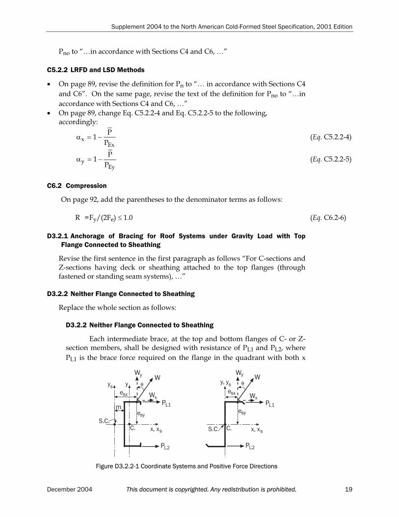
Each intermediate brace, at the top and bottom flanges of C- or Z-section members, shall be designed with resistance of PL1 and PL2, where
PL1 is the brace force required on the flange in the quadrant with both x
�
$%�%
&
&
&
�
'
θ' '
�(��
�
'
�%
)��
)��
$%�%
&
&
&
�
'
θ''(
�(��
�
'
�%
)��
)��
Figure D3.2.2-1 Coordinate Systems and Positive Force Directions
December 2004 This document is copyrighted. Any redistribution is prohibited. 19

Supplement 2004 to the North American Cold-Formed Steel Specification, 2001 Edition
and y axes positive, and PL2 is the brace force on the other flange. The x-
axis is the centroidal axis perpendicular to the web, the y-axis is thecentroidal axis parallel to the web. The x and y coordinates shall be oriented such that one of the flanges is located in the quadrant with both positive x and y axes. See Figure D3.2.2-1 for illustrations of coordinatesystems and positive force directions.
(a) For uniform loads,
)]d/M()2/W('KW[5.1P zxy1L (Eq. D3.2.2-1)
)]d/M()2/W('KW[5.1P zxy2L (Eq. D3.2.2-2)
When a design load acts through the plane of the web, i.e. Wy = W:
W)d/m(5.1PP 2L1L For C-sections (Eq. D3.2.2-3)
W)I2
I(5.1PP
x
xy2L1L For Z-sections (Eq. D3.2.2-4)
where Wx, Wy = Components of design load W parallel to the x- and y-axis,
respectively. Wx and Wy are positive if pointing to the
positive x- and y- direction, respectively. W = Design load (applied load determined in accordance with
the most critical load combinations for ASD, LRFD or LSD,whichever is applicable) within a distance of 0.5a each side of the brace
a = Longitudinal distance between centerline of braces d = Depth of sectionm = Distance from shear center to mid-plane of web of C-
sectionMz =-Wxesy + Wyesx, Torsional moment of design load W about
shear centeresx, esy= Eccentricities of load components measured from the shear
center and in the x- and y-directions, respectively K’ = 0 for C-section
= Ixy/(2Ix) for Z-section (Eq. D3.2.2-5)
Ixy = Product of inertia of full unreduced section
Ix = Moment of inertia of full unreduced section about x-axis
(b) For concentrated loads,
)d/M()2/P('KPP zxy1L (Eq. D3.2.2-6)
)d/M()2/P('KPP zxy2L (Eq. D3.2.2-7)
When a design load acts through the plane of the web, i.e. Py = P:
P)d/m(PP 2L1L For C-sections (Eq. D3.2.2-8)
P)I2
I(PP
x
xy2L1L For Z-sections (Eq. D3.2.2-9)
where
20 This document is copyrighted. Any redistribution is prohibited. December 2004
Supplement 2004 to the North American Cold-Formed Steel Specification, 2001 Edition
Px, Py = Components of design load P parallel to the x- and y-axis,
respectively. Px and Py are positive if pointing to the
positive x- and y-direction, correspondingly. P = Design concentrated load within a distance of 0.3a on each
side of the brace, plus 1.4(1-l/a) times each designconcentrated load located farther than 0.3a but not fartherthan 1.0a from the brace. The concentrated design load is the applied load determined in accordance with the most critical load combinations for ASD, LRFD or LSD,whichever is applicable.
l = Distance from concentrated load to the brace Mz = -Pxesy + Pyesx, Torsional moment of design load P about
shear centerOther variables are defined under (a).
The bracing force, PL1 or PL2 is positive when restraint is required
to prevent the movement of the corresponding flange in the negative x-direction.
When braces are provided, they shall be attached in such a mannerto effectively restrain the section against lateral deflection of both flanges at the ends and at any intermediate brace points.
When all loads and reactions on a beam are transmitted throughmembers which frame into the section in such a manner as to effectivelyrestrain the section against torsional rotation and lateral displacement, no additional braces shall be required except those required for strength [resistance] according to Section C3.1.2.1.
D4 Wall Studs and Wall Stud Assemblies
Replace the whole section (including the subsections) with the followings:
D4 Wall Studs and Wall Stud Assemblies
Wall studs shall be designed either on the basis of an all steel system inaccordance with Section D4.1 or on the basis of sheathing braced design inaccordance with an appropriate theory, tests, or rational engineering analysis.Both solid and perforated webs shall be permitted. Both ends of the stud shall beconnected to restrain rotation about the longitudinal stud axis and horizontaldisplacement perpendicular to the stud axis.
D4.1 All Steel Design
Wall stud assemblies using an all steel design shall be designed neglecting the structural contribution of the attached sheathings and shall comply with the requirements of Chapter C. For compression members with circular web perforations, see Section B2.2, and for non-circular web perforations, the effective area shall be determined as follows:
The effective area, Ae at a stress Fn, shall be determined in accordance
December 2004 This document is copyrighted. Any redistribution is prohibited. 21

Supplement 2004 to the North American Cold-Formed Steel Specification, 2001 Edition
with Chapter B, assuming the web to consist of two unstiffened elements, one on each side of the perforation, or the effective area, Ae, shall be determined
from stub-column tests.When Ae is determined in accordance with Chapter B, the following
limitations related to the size and spacing of perforations and the depth of the stud shall apply:(1) The center-to-center spacing of web perforations shall not be less than 24
in. (610 mm).(2) The maximum width of web perforations shall be the lesser of 0.5 times
the depth, d, of the section or 2-1/2 in. (63.5 mm).(3) The length of web perforations shall not exceed 4-1/2 in. (114 mm). (4) The section depth-to-thickness ratio, d/t, shall not be less than 20.(5) The distance between the end of the stud and the near edge of a
perforation shall not be less than 10 in. (254 mm).
D5 Floor, Roof or Wall Steel Diaphragm Construction
Replace the whole section as follows:
D5 Floor, Roof or Wall Steel Diaphragm Construction
The in-plane diaphragm nominal shear strength [resistance], Sn shall be
established by calculation or test. Table D5 applies to both methods. Ifnominal shear strength is only established by test without defining all limitstate thresholds, the factors of safety and resistance factors shall be limited by the values given in Table D5 for connection related failure modes.
d =As specified in Table D5 (ASD)
d =As specified in Table D5 (LRFD and LSD)
Note:
TABLE D5Factors of Safety and Resistance Factors for Diaphragms
Limit State Connection Related Panel Buckling2
USA and Mexico Canada USA & Mexico Canada
LoadType or
CombinationsIncluding
ConnectionType1
d(ASD)
d(LRFD)
d(LSD)
d(ASD)
d(LRFD)
d(LSD)
Welds 3.00 0.55EarthquakeScrews 2.50 0.65WeldsWindScrews
2.35 0.70
Welds 2.65 0.60All Others Screws 2.50 0.65
0.50 2.00 0.80 0.75
1 When fastener combinations are used within a diaphragm system, the more severefactor is used.
2 Panel buckling is out of plane buckling and not local buckling at fasteners. The more severe factored limit state controls the design.
22 This document is copyrighted. Any redistribution is prohibited. December 2004

Supplement 2004 to the North American Cold-Formed Steel Specification, 2001 Edition
For mechanical fasteners other than screws: 1) d shall not be less than
the Table D5 values for screws, and 2) d shall not be greater than the Table
D5 values for screws. In addition, the value of d and d using mechanical
fasteners other than screws shall be limited by the and values establishedthrough calibration of the individual fastener shear strength unless sufficient data exist to establish a diaphragm system effect in accordance with Section F1.1. Fastener shear strength calibration must include the diaphragm material type. Calibration of individual fastener shear strengths shall be in accordance with Section F1.1. The test assembly shall be such that the tested failure mode is representative of the design. The impact of the support thickness on thefailure mode shall be considered.
E2 Welded Connections
Change the thickness of the thinnest connected part from “0.18 in. (4.57 mm)”to “3/16 in. (4.76 mm)” two places in the first paragraph of the section.
Add the sentence to the end of the second paragraph “For diaphragmapplications, Section D5 shall be used.”
E2.2 Arc Spot Welds
Revise the first sentence in the first paragraph as follows: “Arc spot welds permitted by this Specification are for welding sheet steel to thickersupporting members or sheet-to-sheet in the flat position.”
Add the following sentence to the end of the second paragraph, “Sheet-to-sheet welds do not require weld washers.”
Section E2.2.1 has been reorganized and revised into two subsections:E2.2.1.1, Minimum Edge Distance, and E2.2.1.2, Shear Strength [Resistance]for Sheet(s) to a Thicker Supporting Member. And a new section E2.2.1.3, Shear Strength [Resistance] for Sheet-to-Sheet Connections, is added. The complete section is provided as follows:
E2.2.1 Shear
E2.2.1.1 Minimum Edge Distance
The distance measured in the line of force from the centerline of a weld to the nearest edge of an adjacent weld or to the end of the connected part toward which the force is directed shall not be less than the value of emin as given below:
emin =tF
P
u
For ASD (Eq. E2.2.1.1-1)
emin =tF
P
u
For LRFD and LSD (Eq. E2.2.1.1-2)
When Fu/Fsy 1.08
December 2004 This document is copyrighted. Any redistribution is prohibited. 23

Supplement 2004 to the North American Cold-Formed Steel Specification, 2001 Edition
USA and Mexico Canada
(ASD) (LRFD) (LSD)
2.20 0.70 0.60
When Fu/Fsy < 1.08
USA and Mexico Canada
(ASD) (LRFD) (LSD)
2.55 0.60 0.50
where P =Required shear strength (nominal force) transmitted by weld
(ASD)
P =Required shear strength [shear force due to factored loads]transmitted by weld
P =Pu (LRFD)
P =Pf (LSD)
t =Total combined base steel thickness (exclusive of coatings) of sheet(s) involved in shear transfer above plane of maximum shear transfer
Fsy =Yield point as specified in Sections A2.1, A2.2 or A2.3.2
Note: See Figures E2.2.1.1-1 and E2.2.1.1-2 for edge distances of arc welds.
CLmin
EdgeEdge
d
t
≥ eminCL
≥ e
Figure E2.2.1.1-2 Edge Distance for Arc Spot Welds – Double Sheet
CLmin
EdgeEdge
d
t
minCL≥ e
≥ e
Figure E2.2.1.1-1 Edge Distance for Arc Spot Welds – Single Sheet
24 This document is copyrighted. Any redistribution is prohibited. December 2004

Supplement 2004 to the North American Cold-Formed Steel Specification, 2001 Edition
In addition, the distance from the centerline of any weld to the end or boundary of the connected member shall not be less than 1.5d. In nocase shall the clear distance between welds and the end of member be less than 1.0d.
E2.2.1.2 Shear Strength [Resistance] for Sheet(s) Welded to a ThickerSupporting Member
The nominal shear strength [resistance], Pn, of each arc spot weld
between the sheet or sheets and a thicker supporting member shall bedetermined by using the smaller of either
(a) Pn = xx
2e F75.0
d(Eq. E2.2.1.2-1)
USA and Mexico Canada
(ASD) (LRFD) (LSD)
2.55 0.60 0.50
(b) For (da/t) 0.815 uF/E
Pn = 2.20 t da Fu (Eq. E2.2.1.2-2)
USA and Mexico Canada
(ASD) (LRFD) (LSD)
2.20 0.70 0.60
For 0.815 uF/EuF/E < (da/t) < 1.397
uaa
u Ftdt/d
F/E59.51280.0 (Eq. E2.2.1.2-3) Pn =
USA and Mexico Canada
(ASD) (LRFD) (LSD)
2.80 0.55 0.45
For (da/t) 1.397 uF/E
Pn = 1.40 t da Fu (Eq. E2.2.1.2-4)
USA and Mexico Canada
(ASD) (LRFD) (LSD)
3.05 0.50 0.40
wherePn =Nominal shear strength [resistance] of arc spot weld
d =Visible diameter of outer surface of arc spot weldda =Average diameter of arc spot weld at mid-thickness of t where da
= (d - t) for single sheet or multiple sheets not more than four lapped sheets over a supporting member
de =Effective diameter of fused area at plane of maximum shear
transfer
=0.7d - 1.5t 0.55d (Eq. E2.2.1.2-5)t =Total combined base steel thickness (exclusive of coatings) of
sheets involved in shear transfer above plane of maximum shear transfer
December 2004 This document is copyrighted. Any redistribution is prohibited. 25

Supplement 2004 to the North American Cold-Formed Steel Specification, 2001 Edition
Fxx =Tensile strength of electrode classification
Fu =Tensile strength as specified in Section A2.1, A2.2 or A2.3.2
Note: See Figures E2.2.1.2-1 and E2.2.1.2-2 for diameter definitions.
E2.2.1.3 Shear Strength [Resistance] for Sheet-to-Sheet Connections
The nominal shear strength [resistance] for each weld between twosheets of equal thickness shall be determined as follows:
Pn = 1.65tdaFu (Eq. E2.2.1.3-1)
USA and Mexico Canada
(ASD) (LRFD) (LSD)
2.20 0.70 0.60
where
Plane of MaximumShear Transfer
d = d - ta
d = 0.7d - 1.5t < 0.55de
d
d a
tt
t
1
2
de
Figure E2.2.1.2-2 Arc Spot Weld – Double Thickness of Sheet
d = d - ta
d = 0.7d - 1.5t ≤ 0.55de
d
d
d
a
e
t
Figure E2.2.1.2-1 Arc Spot Weld – Single Thickness of Sheet
Pn = Nominal shear strength [resistance] of sheet-to-sheet
connectiond = Visible diameter of the outer surface of arc spot weld da = Average diameter of arc spot weld at mid-thickness of t
= (d - t) de = Effective diameter of fused area at plane of maximum shear
transfer
= 0.7d – 1.5t 0.55d (Eq. E2.2.1.3-2)Fu = Tensile strength of sheet as specified in Section A2.1 or A2.2
In addition, the following limits shall apply:
26 This document is copyrighted. Any redistribution is prohibited. December 2004

Supplement 2004 to the North American Cold-Formed Steel Specification, 2001 Edition
Fu 59 ksi (407 MPa or 4150 kg/cm2)
Fxx > Fu
0.028 in. (0.71 mm) t 0.0635 in. (1.61 mm) Note: See Figure E2.2.1.3-1 for diameter definitions.
E2.2.2 Tension
On page 109, add the unit to constant “3” and the corresponding conversionas follows:
t da Fu 3 kips (13.34 kN)
E4 Screw Connections
Revise the fourth and fifth paragraphs as follows:
The following factor of safety or resistance factor shall be used for the sub-sections of Section E4, except as otherwise indicated.
USA and Mexico Canada
(ASD) (LRFD) (LSD)
3.00 0.50 0.40
����*���+���
����*�,%-�+�%.��/�,%..�
d
d a
t
t
de
Figure E2.2.1.3-1 Arc Spot Weld – Sheet-to-Sheet
Alternatively, design values for a particular application shall be
permitted to be based on tests, with the factor of safety, , and the resistance
factor, , determined according to Chapter F.
Delete the definition for “Pnt” on page 119.
E4.3.3 Shear in Screws
Replace the whole section as follows:
E4.3.3 Shear in Screws
The nominal shear strength [resistance] of the screw shall be taken as Pss.
December 2004 This document is copyrighted. Any redistribution is prohibited. 27
Supplement 2004 to the North American Cold-Formed Steel Specification, 2001 Edition
In lieu of the value provided in Section E4, the factor of safety or theresistance factor shall be permitted to be determined in accordance with
Section F1 and shall be taken as 1.25 3.0 (ASD), /1.25 0.5 (LRFD) or
/1.25 0.4 (LSD).
E4.4.3 Tension in Screws
Replace the whole section as follows:
E4.4.3 Tension in Screws
The nominal tension strength [resistance] of the screw shall be
taken as Pts.
In lieu of the value provided in Section E4, the factor of safety or theresistance factor shall be permitted to be determined in accordance with
Section F1 and shall be taken as 1.25 3.0 (ASD), /1.25 0.5 (LRFD) or
/1.25 0.4 (LSD).
E4.5 Combined Shear and Pull-Over
Add the following new section and the subsections:
E4.5 Combined Shear and Pull-Over
E4.5.1 ASD Method
For screw connections subjected to a combination of shear and tension forces, the following requirement shall be met:
10.1
P
T71.0
P
Q
novns
(Eq. E4.5.1-1)
In addition, Q and T shall not exceed the corresponding allowabledesign strength determined by Sections E4.3 and E4.4, respectively.
wherePns =Nominal shear strength of connection
= 2.7t1dFu1 (Eq. E4.5.1-2)
Pnov =Nominal pull-over strength of connection
= 1.5t1dwFu1 (Eq. E4.5.1-3)
T =Required allowable tension strength of connection Q =Required allowable shear strength of connection dw =Larger of screw head diameter or washer diameter
t1 =Thickness of the member in contact with the screw head
Fu1 =Tensile strength of the member in contact with the screw
head
=2.35
Eq. E4.5.1-1 is valid for connections that meet the following limits:
(1) 0.0285 in. (0.724 mm) t1 0.0445 in. (1.130 mm)
28 This document is copyrighted. Any redistribution is prohibited. December 2004

Supplement 2004 to the North American Cold-Formed Steel Specification, 2001 Edition
(2) No. 12 and No. 14 self-drilling screws with or withoutwashers
(3) dw 0.75 in. (19.1 mm)
(4) Fu1 70 ksi (483 MPa or 4920 kg/cm2)
(5) t2/t1 2.5
For eccentrically loaded connections that produce a non-uniform pull-over force on the fastener, the nominal pull-over strength shall be taken as 50 percent of Pnov.
E4.5.2 LRFD and LSD Methods
For screw connections subjected to a combination of shear and tension forces the following requirements shall be met:
10.1P
T71.0
P
Q
novns
(Eq. E4.5.2-1)
In addition, Q and T shall not exceed the corresponding design
strength determined by Sections E4.3 and E4.4, respectively.
wherePns =Nominal shear strength [resistance] of connection
=2.7t1dFu1 (Eq. E4.5.2-2)
Pnov =Nominal pull-over strength [resistance] of connection
=1.5t1dwFu1 (Eq. E4.5.2-3)
T = Required tension strength [factored tensile force] ofconnection
T =Tu for LRFD
T =Tf for LSD
Q =Required shear strength [factored shear force] of
connection
Q =Vu for LRFD
Q =Vf for LSD
=0.65 (LRFD)=0.55 (LSD)
Eq. E4.5.2-1 is valid for connections that meet the following limits:
(1) 0.0285 in. (0.724 mm) t1 0.0445 in. (1.13 mm)
(2) No. 12 and No. 14 self-drilling screws with or withoutwashers
(3) dw 0.75 in. (19.1 mm)
(4) Fu1 70 ksi (483 MPa or 4920 kg/cm2)
(5) t2/t1 2.5
For eccentrically loaded connections that produce a non-uniform
December 2004 This document is copyrighted. Any redistribution is prohibited. 29

Supplement 2004 to the North American Cold-Formed Steel Specification, 2001 Edition
pull-over force on the fastener, the nominal pull-over strength shall be taken as 50 percent of Pnov.
F1.1 Load and Resistance Factor Design and Limit States Design
In Table F1, the statistic data of “Bearing Strength” of “Screw Connections” (on page 125) were revised from “0.10” to “0.08” for VM and from “0.10” to
“0.05” for VF, respectively.
30 This document is copyrighted. Any redistribution is prohibited. December 2004

Supplement 2004 to the North American Cold-Formed Steel Specification, 2001 Edition
CHANGES AND UPDATES IN APPENDICES A AND C
A2.2 Other Steels
Replace the whole section as follows:
A2.2 Other Steels
The listing in Section A2.1 does not exclude the use of steel up to and including 1 in. (25.4 mm) in thickness, ordered or produced to other than thelisted specifications, provided the following requirements are met: (1) The steel shall conform to the chemical and mechanical requirements of
one of the listed specifications or other published specification.(2) The chemical and mechanical properties shall be determined by the
producer, the supplier, or the purchaser, in accordance with the followingspecifications. For coated sheets, ASTM A924/A924M; for hot-rolled or cold-rolled sheet and strip, ASTM A568/A568M; for plate and bar, ASTM A6/A6M; for hollow structural sections, such tests shall be made in accordance with the requirements of A500 (for carbon steel) or A847 (forHSLA steel).
(3) The coating properties of coated sheet shall be determined by theproducer, the supplier, or the purchaser, in accordance with ASTMA924/A924M.
(4) The steel shall meet the requirements of Section A2.3. (5) If the steel is to be welded, its suitability for the intended welding process
shall be established by the producer, the supplier, or the purchaser inaccordance with AWS D1.1 or D1.3 as applicable.
If the identification and documentation of the production of the steelhave not been established, then in addition to requirements (1) through (5), the manufacturer of the cold-formed product shall establish that the yieldpoint and tensile strength of the master coil are at least 10 percent greater than specified in the referenced published specification.
C3.1.4 Beams Having One Flange Fastened to a Standing Seam Roof System
Revise the definition for R as follows:
R = Reduction factor determined by AISI TS-8, “Base Test Method for Purlins Supporting a Standing Seam Roof System” published by AISI.
C4.7 Compression of Z-Section Members Having One Flange Fastened to aStanding Seam Roof
Add the following new section:
C4.7 Compression of Z-Section Members Having One Flange Fastened to aStanding Seam Roof
These provisions are applicable to Z-sections concentrically loaded
December 2004 This document is copyrighted. Any redistribution is prohibited. 31
Supplement 2004 to the North American Cold-Formed Steel Specification, 2001 Edition
along their longitudinal axis, with only one flange attached to standing seamroof panels. Alternatively, design values for a particular system shall bepermitted to be based on discrete point bracing locations, or on tests according to Chapter F.
The nominal axial strength of simple span or continuous Z-sections shallbe calculated as follows: (a) For weak axis nominal strength
Pn = kafRFyA (Eq. C4.7-1)
= 1.80 (ASD)
= 0.85 (LRFD)where
For d/t 90 kaf = 0.36
For 90 < d/t 130
kaf = t250
d72.0 (Eq. C4.7-2)
For d/t > 130 kaf = 0.20
R =The reduction factor determined from uplift tests performed using AISI TS-8, “Base Test Method for Purlins Supporting a Standing Seam Roof System”, published by AISI.
A =The full unreduced cross-sectional area of Z-section. d = Z-section deptht = Z-section thicknessFy is defined in Section C3.1.1.
Eq. C4.7-1 shall be limited to roof systems meeting the following conditions:
(1) Purlin thickness, 0.054 in. (1.37 mm) t 0.125 in. (3.22 mm)
(2) 6 in. (152 mm) d 12 in. (305 mm)(3) Flanges are edge stiffened compression elements
(4) 70 d/t 170
(5) 2.8 d/b 5
(6) 16 t
widthflatflange 50
(7) Both flanges are prevented from moving laterally at the supports
(8) Yield point, Fy 70 ksi (483 MPa or 4920 kg/cm2)
where b = Z-section flange width.
(b) For strong axis nominal strength, the equations contained in Section C4and C4.1 of the Specification shall be used.
E2a Welded Connections
Change the thickness of connected part from “0.18 in. (4.57 mm)” to “3/16 in.(4.76 mm)” one place in the first paragraph and one place in the secondparagraph.
32 This document is copyrighted. Any redistribution is prohibited. December 2004
Supplement 2004 to the North American Cold-Formed Steel Specification, 2001 Edition
E3a Bolted Connections
Add the following content to the end of the third paragraph:
In the situation where the hole occurs within the lap of lapped and nestedzee members, the above requirements regarding the direction of the slot and theuse of washers do not apply, subject to the following restrictions:
1) 1/2 in. (12.7 mm) diameter bolts only 2) Maximum slot size is 9/16 in. x 7/8 in. (14.3 mm x 22.2 mm) slotted
vertically3) Maximum oversize hole is 5/8 in. (15.9 mm) diameter 4) Minimum member thickness is 0.060 in. (1.52 mm) nominal5) Maximum member yield stress is 60 ksi (410 MPa, and 4220 kg/cm2)6) Minimum lap length measured from center of frame to end of lap is 1.5
times the member depth.
E5.3 Block Shear Rupture
Replace the whole section with the followings:
E5.3 Block Shear Rupture
The block shear rupture nominal strength, Rn, shall be determined as
follows when the thickness of the thinnest connected part is less than 3/16 in. (4.76 mm). For connections in which the thickness of the thinnest connected part is equal to or greater than 3/16 in. (4.76 mm), refer to AISC “Specification for Structural Steel Buildings, Allowable Stress Design and Plastic Design”, or the “Load and Resistance Factor Design Specification for Structural Steel Buildings”.
The nominal block shear rupture strength, Rn, shall be determined as
the lesser of the following:
ntugvyn AFAF6.0R (Eq. E5.3-1)
ntunvun AFAF6.0R (Eq. E5.3-2)
For bolted connections:
= 2.22 (ASD)
=0.65 (LRFD)For welded connections:
= 2.50 (ASD)
=0.60 (LRFD)where Agv = Gross area subject to shear
Anv = Net area subject to shear
Ant = Net area subject to tension
December 2004 This document is copyrighted. Any redistribution is prohibited. 33

Supplement 2004 to the North American Cold-Formed Steel Specification, 2001 Edition
CHANGES AND UPDATES IN APPENDIX B
A2.2.1 Other Structural Quality Steels
On the third line in the section, change “published material Specification” to “published Specification”.
A2.4a Delivered Minimum Thickness
Delete the entire section.
A3.1 Specified Loads
Replace the whole section as follows:
A3.1 Loads and Effects
The following loads, forces, and effects shall be considered in the design of cold-formed steel structural members and their connections: D dead load, a permanent load due to the weight of building components,
including the mass of the member and all permanent materials of construction, partitions, permanent equipment, and the mass ofsupported earth, plants and trees, multiplied by the acceleration due togravity to convert mass (kg) to force (N)
E earthquake load and effects, a rare load due to earthquake L live load, a variable load due to intended use and occupancy, including
loads due to movable equipment, cranes, pressure of liquids in containers S variable load due to snow, including ice and associated rain, or rain T effects due to contraction, expansion, or deflection caused by temperature
changes, shrinkage, moisture changes, creep, temperature, ground settlement, or combination thereof
W wind load, a variable load due to wind H a permanent load due to lateral earth pressure, including groundwater
A3.2 Temperature Effects
Replace the whole section as follows:
A3.2 Temperature, Earth and Hydrostatic Pressure Effects
Where the effects due to lateral earth pressure H and imposed deformation T affect the structural safety, they shall be taken into account in the calculations, H with a load factor of 1.5 and T with a load factor of 1.25.
A6.1.2 Load Factors and Load Combinations for LSD
Replace the whole section, including the subsections A6.1.2.1, Load Factors
( ), A6.1.2.2, Load Combination Factor ( ), and A6.1.2.3, Importance Factors
( ), as follows:
34 This document is copyrighted. Any redistribution is prohibited. December 2004

Supplement 2004 to the North American Cold-Formed Steel Specification, 2001 Edition
A6.1.2 Load Factors and Load Combinations for LSD
The effect of factored loads for a building or structural componentshall be determined in accordance with the load combinations listed inTable B-A6.1.2-1, the applicable combination being that which results in themost critical effect.
Table B-A6.1.2-1 Load Combinations for Ultimate Limit States
Load CombinationCASE
Principal Loads Companion Loads
1 1.4D
2 (1.25D(4) or 0.9D(4)) + 1.5L(2) 0.5S or 0.4W
3 (1.25D(4) or 0.9D(4)) + 1.5S 0.5L(3) or 0.4W
4 (1.25D(4) or 0.9D(4)) + 1.4W 0.5L(3) or 0.5S
5 1.0D(1) + 1.0E(5) 0.5L(3) + 0.25S
Notes to Table B-A6.1.2-1:(1) Except for rocking footings, the counteracting factored dead load, 0.9D in load
combinations (2), (3) and (4) and 1.0D in load combination (5), shall be used
when dead load acts to resist overturning, uplift, sliding, failure due to stress
reversal, and to determine anchorage requirements and factored member
resistances.(2) The principal-load factor 1.5 for live load L may be reduced to 1.25 for liquids in
tanks.(3) The companion-load factor 0.5 for live load L shall be increased to 1.0 for storage
occupancies, and equipment areas and service rooms.(4) The load factor 1.25 for dead load D for soil, superimposed earth, plants and
trees shall be increased to 1.5, except that when the soil depth exceeds 1.2m, thefactor may be reduced to 1+0.6/hs, but not less than 1.25, where hs is the depth
of soil in metres supported by the structure. (5) Earthquake load E in load combination (5) includes horizontal earth pressure
due to earthquake.
A6.1.2.1. Importance Categories
For the purpose of determining specified loads S, W or E, buildingsshall be assigned an Importance Category, based on intended use andoccupancy, in accordance with Table B-A6.1.2.1-1.
December 2004 This document is copyrighted. Any redistribution is prohibited. 35

Supplement 2004 to the North American Cold-Formed Steel Specification, 2001 Edition
Table A6.1.2.1-1Importance Categories for Buildings
USE AND OCCUPANCY ImportanceCategory
Buildings that represent a low direct or indirect hazard to humanlife in the event of failure including:
Low human-occupancy buildings, where it can be shown that collapse is not likely to cause injury or other seriousconsequences
Minor storage buildings(1)
Low
All buildings except those listed in Categories Low, High and Post-disaster
Normal
Buildings that are likely to be used as post-disaster shelters,including buildings whose primary use is:
Elementary, middle and secondary schools
Community centres
Manufacturing and storage facilities containing toxic, explosive or other hazardous substances in sufficient quantities to be dangerous to the public if released(1)
High
Post-disaster buildings including:
Hospitals, emergency treatment facilities and blood banks
Telephone exchanges
Power generating stations and electrical substations
Control centres for air, land and marine transportation
Public water treatment and storage facilities and pumpingstations
Sewage treatment facilities
Buildings of the following types unless exempted from this designation by the authority having jurisdiction:
emergency response facilities
fire, rescue and police stations and housing for vehicles, aircraftor boats used for such purposes
communications facilities including radio and television stations
PostDisaster
For buildings having a Low Importance Category, a factor of 0.8 maybe applied to the live load, L.
A6.1.2.2 Importance Factor (I)
The importance factor for snow, wind and earthquake shall be asprovided for in Table B-A6.1.2.2-1
Importance Factor for Ultimate Limit States ImportanceCategory Snow, IS Wind, IW Earthquake, IE
Low 0.8 0.8 0.8
Normal 1.0 1.0 1.0
High 1.15 1.15 1.3
Post-Disaster 1.25 1.25 1.5
36 This document is copyrighted. Any redistribution is prohibited. December 2004

Supplement 2004 to the North American Cold-Formed Steel Specification, 2001 Edition
A9a Reference Documents
Change the publication year for National Building Code of Canada from “1995”to “2005”.
C2.2 Fracture of Net Section
Revise Eq. C2.2-4 to “Lc = 0.6Lnv”.
Add the following after Eq. C2.2-6:
(d) For failure of coped beams: Lc = 0.5Lt + 0.6Lv not involving stagger (Eq. C2.2-7)
Lc = 0.45(Lt + Ls)+ 0.6Lv involving stagger (Eq. C2.2-8)
where in (c) and (d), Lv is the lesser of CLgv or Lnv
C = Fy/Fu (Eq. C2.2-9)
Delete the definition for Lv and add the following two new definitions:
Lgv = Gross failure path length parallel to force (i.e., in shear)
Lnv = Net failure path length parallel to force (i.e., in shear)
E2a Welded Connections
On the first and the third lines of the second paragraph, change the thicknesslimit from “4.57 mm” to “4.76 mm”.
E3a Bolted Connections
Add the following to the end of the section:
Slotted of oversized holes may be used when the hole occurs within thelap of lapped or nested Z-members, subject to the following restrictions: (1) 12.7 mm diameter bolts only, with or without washers (2) Maximum slot size is 14.3 x 22.2 mm slotted vertically (3) Maximum oversize hole is 15.9 mm diameter(4) Minimum member thicknesses is 1.52 mm nominal(5) Maximum member yield stress is 410 MPa (6) Minimum lap length measured from centre of frame to end of lap is 1.5
times the member depth.
E3.4 Shear and Tension in Bolts
In the first line of the section, change “less than or equal to” to “less than”.
December 2004 This document is copyrighted. Any redistribution is prohibited. 37
Supplement 2004 to the North American Cold-Formed Steel Specification, 2001 Edition
Appendix 1, Design of Cold-Formed Steel Structural Members Using the Direct Strength Method
Appendix 1 is a newly added appendix.
38 This document is copyrighted. Any redistribution is prohibited. December 2004

Appendix 1
Design of Cold-Formed Steel
Structural Members Using
the Direct Strength Method
2004 EDITION
Supplement 2004 to the North American Cold-Formed Steel Specification, 2001 Edition – Appendix 1
PREFACEThis Appendix provides alternative design procedures to portions of the North American
Specification for the Design of Cold-Formed Steel Structural Members, Chapters A through G, and Appendices A through C (herein referred to as the main Specification). The Direct Strength Method detailed in this Appendix requires determination of the elastic buckling behavior of the member, and then provides a series of nominal strength [resistance] curves for predicting themember strength based on the elastic buckling behavior. The procedure does not requireeffective width calculations, nor iteration, and instead uses gross properties and the elastic buckling behavior of the cross-section to predict the strength. The applicability of these provisions is detailed in the General Provisions of this Appendix.
Appendix 1-2 This document is copyrighted. Any redistribution is prohibited. December 2004

Supplement 2004 to the North American Cold-Formed Steel Specification, 2001 Edition – Appendix 1
TABLE OF CONTENTS
APPENDIX 1: DESIGN OF COLD-FORMED STEEL STRUCTURAL MEMBERSUSING THE DIRECT STRENGTH METHOD
1.1 GENERAL PROVISIONS ........................................................................................................... A1-41.1.1 Applicability .........................................................................................................................A1-4
1.1.1.1 Pre-qualified Columns........................................................................................A1-51.1.1.2 Pre-qualified Beams ............................................................................................A1-6
1.1.2 Elastic Buckling ....................................................................................................................A1-71.1.3 Serviceability Determination..............................................................................................A1-7
1.2 MEMBERS ............................................................................................................................... A1-71.2.1 Column Design ....................................................................................................................A1-7
1.2.1.1 Flexural, Torsional, or Torsional-Flexural Buckling.......................................A1-71.2.1.2 Local Buckling......................................................................................................A1-81.2.1.3 Distortional Buckling ..........................................................................................A1-8
1.2.2 Beam Design.........................................................................................................................A1-81.2.2.1 Lateral-Torsional Buckling.................................................................................A1-91.2.2.2 Local Buckling......................................................................................................A1-91.2.2.3 Distortional Buckling ..........................................................................................A1-9
December 2004 This document is copyrighted. Any redistribution is prohibited. Appendix 1-3

Supplement 2004 to the North American Cold-Formed Steel Specification, 2001 Edition – Appendix 1
APPENDIX 1: DESIGN OF COLD-FORMED STEEL STRUCTURAL MEMBERS USING THE DIRECT STRENGTH METHOD
1.1 GENERAL PROVISIONS
1.1.1 Applicability
The provisions of this Appendix are applicable for determination of the nominal axial (Pn) and flexural (Mn) strengths of cold-formed steel members.
Sections 1.2.1 and 1.2.2 present a method applicable to all cold-formed steel beams and columns. Those members meeting the geometric and material limitations of Section 1.1.1.1 for columns and section 1.1.1.2 for beams have been
pre-qualified for use, and the calibrated safety factor, , and resistance factor, ,given in 1.2.1 and 1.2.2 apply. Other beams and columns shall be permitted to
use the provisions of Sections 1.2.1 and 1.2.2, but the standard and factors for rational analysis (Section A1.1(b) of the main Specification ) apply.
Currently, the Direct Strength Method provides no explicit provisions for members in tension, shear, combined bending and shear, web crippling,combined bending and web crippling, or combined axial load and bending(beam-columns). Further, no provisions are given for structural assemblies or connections and joints. As detailed in main Specification Section A1.1, the provisions of the main Specification, when applicable, shall be used for all cases listed above.
It shall be permitted to substitute the nominal strengths [resistances],resistance factors and factors of safety from this Appendix for the correspondingvalues from Sections C3.1, C4.1, C4.2, C4.3 and C4.4 of the main Specification.
For members or situations to which the main Specification is not applicable,obvious extensions to the Direct Strength Method of this Appendix may exist. Users who choose to employ such extensions to the Direct Strength Method are subject to the same provisions as any other rational analysis procedure asdetailed in Section A1.1(b) of the main Specification: (1) applicable provisions ofthe main Specification must be followed when they exist, and (2) increased safety
factors, and reduced resistance factors, are employed for strength when rational analysis is conducted.
Note:
The North American Specification for the Design of Cold-Formed Steel Structural
Members, Chapters A through G and Appendices A through C is herein referred to as
the main Specification.
Appendix 1-4 This document is copyrighted. Any redistribution is prohibited. December 2004
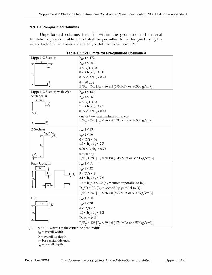
Supplement 2004 to the North American Cold-Formed Steel Specification, 2001 Edition – Appendix 1
1.1.1.1 Pre-qualified Columns
Unperforated columns that fall within the geometric and material limitations given in Table 1.1.1-1 shall be permitted to be designed using the
safety factor, , and resistance factor, , defined in Section 1.2.1.
Table 1.1.1-1 Limits for Pre-qualified Columns(1)
Lipped C-Section
θ
0
#
��
�
ho/t < 472
bo/t < 159
4 < D/t < 33 0.7 < ho/bo < 5.0
0.05 < D/bo < 0.41
= 90 deg E/Fy > 340 [Fy < 86 ksi (593 MPa or 6050 kg/cm2)]
Lipped C-Section with Web Stiffener(s)
θ
0
#
��
�
ho/t < 489
bo/t < 160
6 < D/t < 33 1.3 < ho/bo < 2.7
0.05 < D/bo < 0.41
one or two intermediate stiffeners E/Fy > 340 [Fy < 86 ksi ( 593 MPa or 6050 kg/cm2)]
Z-Section0
#
��
�
θ
ho/t < 137
bo/t < 56
0 < D/t < 36 1.5 < ho/bo < 2.7
0.00 < D/bo < 0.73
= 50 deg E/Fy > 590 [Fy < 50 ksi ( 345 MPa or 3520 kg/cm2)]
Rack Upright
�
#
��
�
�
���
ho/t < 51
bo/t < 22
5 < D/t < 8 2.1 < ho/bo < 2.9
1.6 < b2/D < 2.0 (b2 = stiffener parallel to bo)
D2/D = 0.3 (D2 = second lip parallel to D)
E/Fy = 340 [Fy < 86 ksi (593 MPa or 6050 kg/cm2)]
Hat
#
��
�
�
ho/t < 50
bo/t < 20
4 < D/t < 6 1.0 < ho/bo < 1.2
D/bo = 0.13
E/Fy > 428 [Fy < 69 ksi ( 476 MPa or 4850 kg/cm2)]
(1) r/t < 10, where r is the centerline bend radius bo = overall width
D = overall lip deptht = base metal thicknessho = overall depth
December 2004 This document is copyrighted. Any redistribution is prohibited. Appendix 1-5

Supplement 2004 to the North American Cold-Formed Steel Specification, 2001 Edition – Appendix 1
1.1.1.2 Pre-qualified Beams
Unperforated beams that fall within the geometric and material limitations given in Table 1.1.1-2 shall be permitted to be designed using the
safety factor, , and resistance factor, , defined in Section 1.2.2.
Table 1.1.1-2 Limitations for Pre-qualified Beams(1)
C-Sections
θ
0
#
��
�
ho/t < 321
bo/t < 75
0 < D/t < 34 1.5 < ho/bo < 17.0
0 < D/bo < 0.70
44 deg < < 90 degE/Fy > 421 [Fy < 70 ksi (483 MPa or 4920 kg/cm2)]
Lipped C-Sections with Web Stiffener
θ
0
#
��
�
ho/t < 358
bo/t < 58
14 < D/t < 175.5 < ho/bo < 11.7
0.27 < D/bo < 0.56
= 90 deg E/Fy > 578 [Fy < 51 ksi (352 MPa or 3590 kg/cm2)]
Z-Sections0
#
��
�
θ
ho/t < 183
bo/t < 71
10 < D/t < 162.5 < ho/bo < 4.1
0.15 < D/bo < 0.34
36 deg < < 90 degE/Fy > 440 [Fy < 67 ksi (462 MPa or 4710 kg/cm2)]
Hats (Decks) with stiffened flange in compression
�
#
��
�
�
�
ho/t < 97
bo/t < 467
0 < ds/t < 26 (depth of stiffener)
0.14 < ho/bo < 0.87
0.88 < bo/bt < 5.4
0 < n 4 (number of compression flange stiffeners) E/Fy > 492 [Fy < 60 ksi ( 414 MPa or 4220 kg/cm2)]
Trapezoids (Decks) with stiffenedflange in compression
�
#
��
�
θ
�
ho/t < 203
bo/t < 231
0.42 < (ho/sin )/bo < 1.91
1.10 < bo/bt < 3.38
0 < nc 2 (number of compression flange stiffeners)
0 < nw 2 (number of web stiffener/folds)
0 < nt 2 (number of tension flange stiffeners)
52 deg < < 84 deg (angle between web and horizontal plane)E/Fy > 310 [Fy < 95 ksi (655 MPa or 6680 kg/cm2)]
(1) r/t < 10, where r is the centerline bend radius. See section 1.1.1.1 for definitions of other variables given in Table 1.1.1-2.
Appendix 1-6 This document is copyrighted. Any redistribution is prohibited. December 2004
Supplement 2004 to the North American Cold-Formed Steel Specification, 2001 Edition – Appendix 1
1.1.2 Elastic Buckling
Analysis is required for determination of the elastic buckling loads and or moments used in this Appendix. For columns, this includes the local, distortionaland overall buckling loads: Pcr , Pcrd, and Pcre of Section 1.2.1. For beams, thisincludes the local, distortional and overall buckling moments: Mcr , Mcrd, and Mcre of Section 1.2.2. For a given column or beam, all three modes may not exist. In this case, the non-existent mode shall be ignored in the calculations of Sections 1.2.1 and 1.2.2. The commentary to this Appendix provides guidance on appropriate analysis procedures for elastic buckling determination.
1.1.3 Serviceability Determination
The bending deflection at any moment (M) due to nominal loads, shall be permitted to be determined by reducing the gross moment of inertia, Ig, to an effective moment of inertia for deflection, as given in Eq. 1.1.3-1:
Ieff = Ig(Md/M) Ig (Eq. 1.1.3-1)
whereMd= Nominal strength Mn defined in Section 1.2.2, but with My replaced
by M in all formulas of Section 1.2.2. M = Moment due to nominal loads [specified moments] on member to be
considered (M My)
1.2 MEMBERS
1.2.1 Column Design
The nominal axial strength, Pn, is the minimum of Pne, Pn and Pnd as given
in Sections 1.2.1.1 to 1.2.1.3. For columns meeting the geometric and material
criteria of Section 1.1.1.1, c and c are as follows:
USA and Mexico Canada
c (ASD) c (LRFD) c (LSD)
1.80 0.85 0.80
For all other columns, and of main Specification Section A1.1(b) apply.
1.2.1.1 Flexural, Torsional, or Torsional-Flexural Buckling
The nominal axial strength, Pne, for flexural, torsional, or torsional-
flexural buckling isfor 5.1c
Pne = (Eq. 1.2.1-1)yP658.02c
for c > 1.5
Pne = y2c
P877.0
(Eq. 1.2.1-2)
where c = crey PP (Eq. 1.2.1-3)
Py = AgFy (Eq. 1.2.1-4)
December 2004 This document is copyrighted. Any redistribution is prohibited. Appendix 1-7

Supplement 2004 to the North American Cold-Formed Steel Specification, 2001 Edition – Appendix 1
Pcre= Minimum of the critical elastic column buckling load in
flexural, torsional, or torsional-flexural buckling determined inaccordance with Section 1.1.2
1.2.1.2 Local Buckling
The nominal axial strength, Pn , for local buckling is
for 776.0
Pn =Pne (Eq. 1.2.1-5)
for > 0.776
Pn = ne
4.0
ne
cr4.0
ne
cr PP
P
P
P15.01 (Eq. 1.2.1-6)
where = crne PP (Eq. 1.2.1-7)
Pcr = Critical elastic local column buckling load determined in
accordance with Section 1.1.2 Pne is defined in Section 1.2.1.1.
1.2.1.3 Distortional Buckling
The nominal axial strength, Pnd, for distortional buckling is
for d 561.0
Pnd = Py (Eq. 1.2.1-8)
for d > 0.561
Pnd = y
6.0
y
crd
6.0
y
crd PP
P
P
P25.01 (Eq. 1.2.1-9)
where d = crdy PP (Eq. 1.2.1-10)
Pcrd = Critical elastic distortional column buckling load determined
in accordance with Section 1.1.2Py is given in Eq. 1.2.1-4.
1.2.2 Beam Design
The nominal flexural strength, Mn, is the minimum of Mne, Mn and Mnd as
given in Sections 1.2.2.1 to 1.2.2.3. For beams meeting the geometric and material
criteria of Section 1.1.1.2, b and b are as follows:
USA and Mexico Canada
b (ASD) b (LRFD) b (LSD)
1.67 0.90 0.85
For all other beams, and of main Specification Section A1.1(b) apply.
Appendix 1-8 This document is copyrighted. Any redistribution is prohibited. December 2004
Supplement 2004 to the North American Cold-Formed Steel Specification, 2001 Edition – Appendix 1
1.2.2.1 Lateral-Torsional Buckling
The nominal flexural strength, Mne, for lateral-torsional buckling is
for Mcre < 0.56My
Mne = Mcre (Eq. 1.2.2-1)
for 2.78My > Mcre > 0.56My
Mne =cre
yy
M36
M101M
9
10(Eq. 1.2.2-2)
for Mcre > 2.78My
Mne = My (Eq. 1.2.2-3)
whereMy = SfFy, where Sf is the gross section modulus referenced to (Eq. 1.2.2-4)
the extreme fiber in first yield Mcre = Critical elastic lateral-torsional buckling moment determined
in accordance with Section 1.1.2
1.2.2.2 Local Buckling
The nominal flexural strength, Mn , for local buckling is
for 776.0
Mn = Mne (Eq. 1.2.2-5)
for > 0.776
Mn = ne
4.0
ne
cr4.0
ne
cr MM
M
M
M15.01 (Eq. 1.2.2-6)
where = crne MM (Eq. 1.2.2-7)
Mcr = Critical elastic local buckling moment determined in
accordance with Section 1.1.2Mne is defined in Section 1.2.2.1.
1.2.2.3 Distortional Buckling
The nominal flexural strength, Mnd, for distortional buckling is
for d 673.0
Mnd =My (Eq. 1.2.2-8)
for d > 0.673
Mnd = y
5.0
y
crd
5.0
y
crd MM
M
M
M22.01 (Eq. 1.2.2-9)
where d = crdy MM (Eq. 1.2.2-10)
Mcrd = Critical elastic distortional buckling moment determined in
accordance with Section 1.1.2.My is given in Eq. 1.2.2-4.
December 2004 This document is copyrighted. Any redistribution is prohibited. Appendix 1-9

Supplement 2004 to the Commentary
on the North American Specification
for the Design of Cold-Formed
Steel Structural Members
2001 EDITION

The material contained herein has been developed by a joint effort of the American Ironand Steel Institute Committee on Specifications, the Canadian Standards Association Technical Committee on Cold Formed Steel Structural Members (S136), and Camara Nacional de la Industria del Hierro y del Acero (CANACERO) in Mexico. The organizations and theCommittees have made a diligent effort to present accurate, reliable, and useful information on cold-formed steel design. The Committees acknowledge and are grateful for the contributionsof the numerous researchers, engineers, and others who have contributed to the body of knowledge on the subject. Specific references are included in the Supplement to the Commentaryon the Specification.
With anticipated improvements in understanding of the behavior of cold-formed steel and the continuing development of new technology, this material may eventually become dated. It is anticipated that future editions of this specification will update this material as new information becomes available, but this cannot be guaranteed.
The materials set forth herein are for general information only. They are not a substitute for competent professional advice. Application of this information to a specific project should be reviewed by a registered professional engineer. Indeed, in most jurisdictions, such review isrequired by law. Anyone making use of the information set forth herein does so at their ownrisk and assumes any and all resulting liability arising therefrom.
1st Printing –January 2005
Produced by American Iron and Steel Institute
Copyright American Iron and Steel Institute 2005
Supplement 2004 to the Commentary on the North American Cold-Formed Steel Specification, 2001 Edition
TABLE OF CONTENTS
SUPPLEMENT 2004 TO THE COMMENTARY ON THE NORTH AMERICANSPECIFICATION FOR THE DESIGN OF COLD-FORMED STEEL
STRUCTURAL MEMBERS, 2001 EDITION
DECEMBER, 2004 CHANGES AND UPDATES IN CHAPTERS A THROUGH G .......................................................................5
A1.1 Scope and Limits of Applicability ......................................................................................... 5A2.1 Applicable Steels ...................................................................................................................... 5A2.3 Ductility ..................................................................................................................................... 5A2.4 Delivered Minimum Thickness.............................................................................................. 6A7.2 Strength Increase from Cold Work of Forming ................................................................... 6B2.2 Uniformly Compressed Stiffened Elements with Circular Holes ..................................... 6B3.2 Unstiffened Elements and Edge Stiffeners with Stress Gradient ...................................... 6B5 Effective Widths of Stiffened Elements with Multiple Intermediate Stiffeners or
Edge Stiffened Elements with Intermediate Stiffeners ....................................................... 8B5.2 Edge Stiffened Elements with Intermediate Stiffeners ...................................................... 8C3.1.1 Nominal Section Strength ....................................................................................................... 8C3.1.2.1 Lateral-Torsional Buckling Strength [Resistance] for Open Cross Section Members .... 9C3.1.2.2 Lateral-Torsional Buckling Strength [Resistance] for Closed Box Members................... 9C3.1.5 Strength [Resistance] of Standing Seam Roof Panel Systems ............................................ 9C3.3 Strength [Resistance] for Combined Bending and Shear ................................................. 10C3.4.1 Web Crippling Strength [Resistance] of Webs without Holes......................................... 10C3.5.1 ASD Method ........................................................................................................................... 13C3.5.2 LRFD and LSD Methods ....................................................................................................... 13C3.6 Stiffeners.................................................................................................................................. 14C4 Concentrically Loaded Compression Members ................................................................ 15C4.4 Nonsymmetric Sections......................................................................................................... 15C4.5 Built-Up Members.................................................................................................................. 15C4.6 Compression Members Having One Flange Through-Fastened to Deck or
Sheathing................................................................................................................................. 15C4.7 Compression of Z-Section Members Having One Flange Fastened to a Standing
Seam Roof................................................................................................................................ 15C6.2 Compression ........................................................................................................................... 15D1.1 I-Sections Composed of Two C-Sections ............................................................................ 16D3.2.2 Neither Flange Connected to Sheathing ............................................................................. 16D4 Wall Studs and Wall Stud Assemblies ................................................................................ 19D5 Floor, Roof or Wall Steel Diaphragm Construction .......................................................... 19E2.2.1 Shear......................................................................................................................................... 21E4 Screw Connections................................................................................................................. 22E4.3.3 Shear in Screws....................................................................................................................... 22E4.4.3 Tension in Screws................................................................................................................... 23E4.5 Combined Shear and Pull-Over ........................................................................................... 23F1.1 Load and Resistance Factor Design and Limit States Design.......................................... 24F3.1 Full Section.............................................................................................................................. 24
December 2004 This document is copyrighted. Any redistribution is prohibited. 3
Supplement 2004 to the Commentary on the North American Cold-Formed Steel Specification, 2001 Edition
G. DESIGN OF COLD-FORMED STEEL STRUCTURAL MEMBERS AND CONNECTIONS FOR CYCLIC LOADING (FATIGUE).................................................. 24
REFERENCES......................................................................................................................................... 24
CHANGES AND UPDATES IN APPENDICES A AND C .......................................................................... 26A2.2 Other Steels ............................................................................................................................. 26C3.1.4 Beam Having One Flange Fastened to a Standing Seam Roof System........................... 27C4.7 Compression of Z-Section Members Having One Flange Fastened to a Standing
Seam Roof................................................................................................................................ 27E2a Welded Connections.............................................................................................................. 27E3a Bolted Connections ................................................................................................................ 28E5 Rupture.................................................................................................................................... 28
CHANGES AND UPDATES IN APPENDIX B........................................................................................... 29A2.4a Delivered Minimum Thickness............................................................................................ 29A3 Loads........................................................................................................................................ 29C2.2 Fracture of Net Section .......................................................................................................... 29
COMMENTARY ON APPENDIX 1, DESIGN OF COLD-FORMED STEEL STRUCTURALMEMBERS USING THE DIRECT STRENGTH METHOD......................................................................... 29
4 This document is copyrighted. Any redistribution is prohibited. December 2004
Supplement 2004 to the Commentary on the North American Cold-Formed Steel Specification, 2001 Edition
SUPPLEMENT 2004 TO THE COMMENTARY ON THENORTH AMERICAN SPECIFICATION FOR THE DESIGN OF
COLD-FORMED STEEL STRUCTURAL MEMBERS, 2001 EDITION
DECEMBER, 2004
CHANGES AND UPDATES IN CHAPTERS A THROUGH G
A1.1 Scope and Limits of Applicability
On line 22 of page 11, add a sentence as follows “…sound engineering judgment. Safety and resistance factors are provided for ease of use, but thesefactors should not be used if applicable safety factors or resistance factors in the main Specification are more conservative.”
Add the following as the last paragraph of the section:
In 2004, Appendix 1, Design of Cold-Formed Steel Structural Members Using the Direct Strength Method, was introduced. The Appendix providesan alternative design procedure for several Sections of Chapters C. The DirectStrength Method detailed in Appendix 1 requires (1) determination of the elastic buckling behavior of the member, and then provides (2) a series of nominal strength [resistance] curves for predicting the member strength based on the elastic buckling behavior. The procedure does not require effectivewidth calculations, nor iteration, and instead uses gross section properties and the elastic buckling behavior of the cross-section to predict the strength. The applicability of the provided provisions is detailed in the General Provisionsof Appendix 1.
Add the following to the end of the section as the third note:
The Specification Chapters A through G and Appendices A through C is
herein referred to as the main Specification.
A2.1 Applicable Steels
Add the following content to the end of the last paragraph:
In 2004, the Specification listing of ASTM A1003/A1003M steel wasrevised to list only the grades designated Type H, because this is the only grade that satisfies the criterion for unrestricted usage. Grades designatedType L can still be used but are subject to the restrictions of A2.3.1.
A2.3 Ductility
On line 11 from the bottom of page 18, change “Part VIII” to “Part VI”
Revise the fifth paragraph of the section as follows:
December 2004 This document is copyrighted. Any redistribution is prohibited. 5

Supplement 2004 to the Commentary on the North American Cold-Formed Steel Specification, 2001 Edition
In the past, the yield point used in design was limited to 75 percent of the specified minimum yield point, or 60 ksi (414 MPa or 4220 kg/cm2), and the tensile strength used in design was limited to 75 percent of the specifiedminimum tensile strength or 62 ksi (427 MPa or 4360 kg/cm2), whichever waslower. This introduced a higher factor of safety, but still made low ductilitysteels, such as SS Grade 80 and Grade E, useful for the named applications.
In the sixth paragraph of the section, delete the word “recent” on the first line, delete “Clause” on the third line, change “RbFy” to “RbFsy” on the same
line, and change “is” to “was” on the sixth line.
Delete the word “Clause” on the first line of both seventh and eighthparagraphs.
In the ninth paragraph, change “Fy” to “Fsy” on the fifth line.
A2.4 Delivered Minimum Thickness
Delete the point symbol, .
Add the following sentence to the end of the section:
In 2004, the country specific section, A2.4a, was deleted from Appendix B.
B
A7.2 Strength Increase from Cold Work of Forming
Add the following as the first paragraph page 33:
The limitation Fya Fuv places an upper bound on the average yield
point. The intent of the upper bound is to limit stresses in flat elements that may not see significant increases in yield point and tensile strength ascompared to the virgin steel properties.
B2.2 Uniformly Compressed Stiffened Elements with Circular Holes
Add the following paragraph to the end of the section on page 46:
In 2004, the Specification Equation B2.2-2 was revised to provide
continuity at = 0.673.
B3.2 Unstiffened Elements and Edge Stiffeners with Stress Gradient
Replace the whole section with the following:
B3.2 Unstiffened Elements and Edge Stiffeners with Stress Gradient
In concentrically loaded compression members and in flexural members where the unstiffened compression element is parallel to the neutral axis, the stress distribution is uniform prior to local buckling. However, when edge stiffeners of the compression element are present, the compressive stress inthe edge stiffener is not uniform but varies in proportion to the distance from
6 This document is copyrighted. Any redistribution is prohibited. December 2004

Supplement 2004 to the Commentary on the North American Cold-Formed Steel Specification, 2001 Edition
the neutral axis. The unstiffened element (the edge stiffener) in this case hascompressive stress applied at both longitudinal edges. The unstiffenedelement of a section may also be subjected to stress gradients causing tensionat one longitudinal edge and compression at the other longitudinal edge. Thiscan occur in I-sections, plain channel sections and angle sections in minor axisbending.
Previous to the 2001 edition of the Specification, unstiffened elements with stress gradient were designed using the Winter effective width equation(Equation C-B2.1-4) and k=0.43. In 2004, Section B3.2 of the Specificationadopted the effective width method for unstiffened elements with stress gradient proposed by Bambach and Rasmussen (2002a, 2002b and 2002c),based on an extensive experimental investigation of unstiffened plates testedas isolated elements in combined compression and bending. The effective width, b, (measured from the supported edge) of unstiffened elements with stress gradient causing compression at both longitudinal edges, is calculatedusing the Winter equation. For unstiffened elements with stress gradients causing tension at one longitudinal edge and compression at the other longitudinal edge, modified Winter equations are specified when tensionexists at either the supported or the unsupported edges. The effective widthequations apply to any unstiffened element under stress gradient, and are not restricted to particular cross-sections. Figure C-B3.2-1 demonstrates how the effective width of an unstiffened element increases as the stress at thesupported edge changes from compression to tension. As shown in the figure,
the effective width curve is independent of the stress ratio, , when bothedges are in compression. In this case, the effect of stress ratio is accounted for by the plate buckling coefficient, k, which varies with stress ratio and affects
the slenderness, . When the supported edge is in tension and the
0 0.5 1.0 1.5 2.0 2.5 3.0 3.5
Slenderness
0
0.25
0.50
0.75
1.00
1.25
bw----
+
+
+f2 f1
+
+
f2
f1
f
f-----2
1
Compression
Compression
Tension
Tension
Compression
Unwelded plate tests
Welded plate tests
Unwelded plate tests
Welded plate tests
Unwelded plate tests
Welded plate tests
Uniformcompression
Compression atunsupportededge
}
}
b
b
b
b
bCompression
Compression
f
f-----2
1
Figure C-B3.2-1 Effective Width vs. Plate Slenderness
December 2004 This document is copyrighted. Any redistribution is prohibited. 7
Supplement 2004 to the Commentary on the North American Cold-Formed Steel Specification, 2001 Edition
unsupported edge is in compression, both the effective width curve and theplate buckling coefficient depend on the stress ratio, as per Equations B3.2-4 and B3.2-5 of the Specification.
Equations are provided for k, determined from the stress ratio, ,applied to the full element width such that iteration is not required, and k willusually be higher than 0.43. The equations for k are theoretical solutions for long plates assuming simple support along the longitudinal edge. A moreaccurate determination of k by accounting for interaction between adjoining elements is permitted for plain channels in minor axis bending (causing compression at the unsupported edge of the unstiffened element), based onresearch of plain channels in compression and bending by Yiu and Pekoz(2001).
The effective width is located adjacent to the supported edge for all stress ratios, including those producing tension at the unsupported edge. Research has found (Bambach and Rasmussen 2002a) that for theunsupported edge to be effective, tension must be applied over at least half of the width of the element starting at the unsupported edge. For less tension,the unsupported edge will buckle and the effective part of the element is located adjacent to the supported edge. Further, when tension is applied over half of the element or more starting at the unsupported edge, the compressedpart of the element will remain effective for elements with w/t ratios less than the limits set out in Section B1.1 of the Specification.
The method for serviceability determination is based on the method used for stiffened elements with stress gradient in Section B2.3(b) of the Specification.
B5 Effective Widths of Stiffened Elements with Multiple Intermediate Stiffeners or Edge Stiffened Elements with Intermediate Stiffeners
Change the last word in the title from “Stiffeners” to “Stiffener(s)”.
B5.2 Edge Stiffened Elements with Intermediate Stiffeners
Change the last word in the title from “Stiffeners” to “Stiffener(s)”.
Revise the first sentence of the section to “The buckling modes for edge stiffened elements with one or more intermediate stiffeners include:…”
Add the following paragraph to the end of the section:
Stub compression testing performed in 2003 demonstrates the adequacyof this approach (Yang and Hancock, 2003).
C3.1.1 Nominal Section Strength
Add the following paragraph to the end of the section:
In 2004, additional Specification equations are provided in SectionC3.1.1(b) for determining the nominal moment strength [resistance], Mn
based on inelastic reserve capacity, for sections containing unstiffened
8 This document is copyrighted. Any redistribution is prohibited. December 2004

Supplement 2004 to the Commentary on the North American Cold-Formed Steel Specification, 2001 Edition
compression elements under stress gradient. Based on research by Bambach and Rasmussen (2002b, 2002c) on I- and plain channel sections inminor axis bending, a compression strain factor Cy determines the
maximum compressive strain on the unstiffened element of the section.
The Cy values are dependent on the stress ratio and slenderness ratio
of the unstiffened element, determined in accordance with Section B3.2(a) of the Specification.
C3.1.2.1 Lateral-Torsional Buckling Strength [Resistance] for Open Cross Section Members
On lines 14 and 15 from the bottom of page 64, change the equation numbersfrom “C3.1.2.1-14 and C3.1.2.1-15” to “C3.1.2.1-13 and C3.1.2.1-14” and online 11 from the bottom of the same paragraph, change “C3.1.2.1-14” to“C3.1.2.1-13”.
On line 20 of page 65, change the equation numbers from “C3.1.2.1-5 andC3.1.2.1-6” to “C3.1.2.1-4 and C3.1.2.1-5”. On line 11 from the bottom of the same page, change “C3.1.2.1-8 and C3.1.2.1-9” to “C3.1.2.1-7 and C3.1.2.1-8”.
Revise Equations C-C3.1.2.1-15 and C-C3.1.2.1-16 on page 67 as follows,respectively:
5.0
fy
yc2
b
yu
SF
EdIC36.0
K
1L (C-C3.1.2.1-15)
5.0
fy
yc2
b
yu
SF
EdIC18.0
K
1L (C-C3.1.2.1-16)
Add the following paragraph right below Equation C-C3.1.2.1-16 on page 67:
For members with unbraced length, L Lu, or elastic lateral-torsional
buckling stress, Fe 2.78Fy, the flexural strength [moment resistance] is
determined in accordance with C3.1.1(a).
On line 5 from the bottom of page 67, change “…nominal lateral buckling strength…” to “nominal lateral-torsional buckling strength…”
On line 5 of page 69, change “Part VII” to “Part V”.
C3.1.2.2 Lateral-Torsional Buckling Strength [Resistance] for Closed BoxMembers
On line 13 from bottom of page 69, change “C3.1.2.1-3” to “C3.1.2.1-2”.
C3.1.5 Strength [Resistance] of Standing Seam Roof Panel Systems
Replace the first and the second paragraphs with the followings:
Under uplift loading, nominal strength [nominal resistance] of
December 2004 This document is copyrighted. Any redistribution is prohibited. 9

Supplement 2004 to the Commentary on the North American Cold-Formed Steel Specification, 2001 Edition
standing seam roof panels and their attachments or anchors cannot be calculated with accuracy. Therefore, it is necessary to determine thenominal strength [nominal resistance] by testing. Under gravity loading, the nominal strength [nominal resistance] of many panels can be calculated accurately. Three test protocols have been used in this effort: FM 4471developed by Factory Mutual, CEGS 07416 by the Corps of Engineers and E1592 by ASTM. In Supplement No. 1 to the 1996 Edition of theSpecification, (AISI, 1999), only the ASTM E1592-95 procedure wasapproved. In 2004, the Factory Mutual and Corps of Engineers protocolswere also approved, provided that testing was in accordance with the AISItest procedure defined in TS-6. While these test procedures have a common base, none defines a design strength [factored resistance]. Specification Section C3.1.5 and AISI TS-6, “Standard Procedures for Panel and Anchor Structural Tests”, adopted in 1999, added closure to thequestion by defining appropriate resistance and safety factors.
The Specification permits end conditions other than those prescribedby ASTM E1592-01. Areas of the roof plane that are sufficiently far enoughaway from crosswise restraint can be simulated by testing the open/opencondition that was permitted in the 1995 edition of ASTM E1592. Inaddition, eave and ridge configurations that do not provide crosswiserestraint can be evaluated.
In the fourth paragraph of the section change “controlling allowable load” to “design strength” on the fourth line, and change “ultimate load” to “nominal strength” on the fifth line.
C3.3 Strength [Resistance] for Combined Bending and Shear
Revise the sentence in the second paragraph to: “…by the following interaction equation (Bleich, 1952), which is part of a unit circle:”.
Add the following after Equation C-C3.3-1:
or
0.1f
f2
cr
2
cr
b (C-C3.3-2)
On page 74, revise the subsequent equation number “C-C3.3-2” to “C-C3.3-3”on line 12, in Figure C-C3.3-1, lines 2 and 4 from bottom of the page; and on page 75, revise the equation number “C-C3.3-2” to “C-C3.3-3” on lines 4, 5, 11and 12.
C3.4.1 Web Crippling Strength [Resistance] of Webs without Holes
In Figures C-C3.4.1-3 and C-C3.4.1-4, the distances from the edge of bearingto the end of the member have been revised as shown in the next two pages.
Add the following sentence after the second sentence in the second to the last paragraph on page 80, “Based on additional updated calibrations, the
10 This document is copyrighted. Any redistribution is prohibited. December 2004
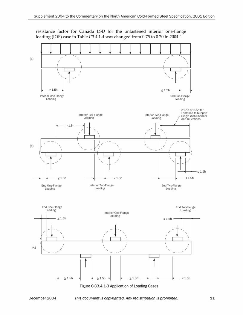
Supplement 2004 to the Commentary on the North American Cold-Formed Steel Specification, 2001 Edition
resistance factor for Canada LSD for the unfastened interior one-flangeloading (IOF) case in Table C3.4.1-4 was changed from 0.75 to 0.70 in 2004.”
!�����+����������������������
< 1.5h
����������+��������������������
> 1.5h
(a)
!���"��+���������������������
< 1.5h
!�����+��������������������
���������"��+���������������������
< 1.5h
< 1.5h< 1.5h
(b)
> 1.5h
��������"��+���������������������
���������"��+���������������������
!���"��+������������������
������������+���������������������
!�����+��������������������
< 1.5h < 1.5h
< 1.5h> 1.5h > 1.5h > 1.5h
(c)
>�%.#�or �%.#�������������$������$�����&���#���������+$�����
Figure C-C3.4.1-3 Application of Loading Cases
December 2004 This document is copyrighted. Any redistribution is prohibited. 11
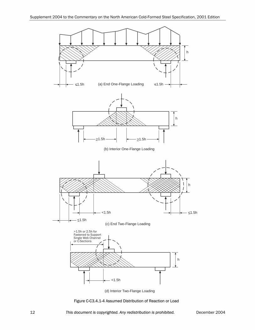
Supplement 2004 to the Commentary on the North American Cold-Formed Steel Specification, 2001 Edition
<1.5h(a) End One-Flange Loading<1.5h
h
(b) Interior One-Flange Loading
>1.5h >1.5h
<1.5h <1.5h
<1.5h(c) End Two-Flange Loading
(d) Interior Two-Flange Loading
h
h
<1.5h
1�%.#�����%.#�������������$������$�����&���#��������+$�����
h
Figure C-C3.4.1-4 Assumed Distribution of Reaction or Load
12 This document is copyrighted. Any redistribution is prohibited. December 2004
Supplement 2004 to the Commentary on the North American Cold-Formed Steel Specification, 2001 Edition
Add the following two paragraphs to the end of the section on page 81:
The previous web crippling coefficients in Table C3.4.1-5 for end one flange loading (EOF) of multi-web deck sections in the design provisions (2001) were based on limited data. This data was based onspecimens that were not fastened to the support during testing, hence, theprevious coefficients for this case were also being used conservatively for the case of fastened to the support. Based on extensive testing, webcrippling coefficients were developed by James A. Wallace (2003) for both the unfastened and fastened case of EOF loading. Calibrations were also carried out to establish the respective factors of safety and resistancefactors.
In 2004, the definitions of “one-flange loading” and “two-flangeloading” were revised according to the test setup, specimen lengths,development of web crippling coefficients, and calibration of factors of safety and resistance factors. In figures C-C3.4.1-3 and C-C3.4.1-4 of theCommentary, the distances from the edge of bearing to the end of themember were revised to be consistent with the Specification.
C3.5.1 ASD Method
Replace the first paragraph of the section with the following:
This Specification contains interaction equations for the combination of bending and web crippling. Specification Equations C3.5.1-1 and C3.5.1-2are based on an evaluation of available experimental data using the webcrippling equation included in the 2001 edition of the Specification(LaBoube, Schuster, and Wallace, 2002). The experimental data is based onresearch studies conducted at the University of Missouri-Rolla (Hetrakuland Yu, 1978 and 1980; Yu, 1981 and 2000), Cornell University (Winter andPian, 1946), and the University of Sydney (Young and Hancock, 2000). Forembossed webs, crippling strength [resistance] should be determined by tests according to Specification Chapter F.
Delete the third paragraph on page 83.
Replace the paragraph starting with “In 2001, …” and the rest of the sectionwith the following:
Based on the test data of LaBoube, Nunnery, and Hodges (1994), in 2004, the interaction equation for the combined effects of bending and web crippling was re-evaluated because a new web crippling equation wasadopted for Section C3.4.1 of the Specification.
C3.5.2 LRFD and LSD Methods
Revise the first sentence in the first paragraph of the section as follows “… are based on the same equations as used for ASD using the required and
December 2004 This document is copyrighted. Any redistribution is prohibited. 13
Supplement 2004 to the Commentary on the North American Cold-Formed Steel Specification, 2001 Edition
design strengths.”
Revise the first sentence of the second paragraph of the section as follows: “Inthe development of the original LRFD equations, …”
Delete the second sentence (to the end of the section) in the last paragraph of the section.
C3.6 Stiffeners
Under this section, the title of Section C3.6.1 has been changed to “BearingStiffeners”. A new section C3.6.2, Bearing Stiffeners in C-Section FlexuralMembers, is added. Accordingly, the subsequent sections are renumbered.
Changes in Section C3.6.1
Change the title of the Section from “Transverse Stiffeners” to “BearingStiffeners”.
Revise the first sentence in the first paragraph to “Design requirements for attached bearing stiffeners (previously called transverse stiffeners) and …”
Add the following sentence as the third sentence in the first paragraph:
The term “transverse stiffener” was renamed to “bearing stiffeners” in2004.
Change “transverse stiffeners” to “bearing stiffeners” on lines 6, 11, 17 and21 in the section.
Add a New Section:
C3.6.2 Bearing Stiffeners in C-Section Flexural Members
The provisions of this section are based on the research by Fox and Schuster (2002), which investigated the behavior of stud and track typebearing stiffeners in cold-formed steel C-section flexural members. These stiffeners fall outside of the scope of Section C3.6.1. The research programinvestigated bearing stiffeners subjected to two-flange loading at bothinterior and end locations, and with the stiffener positioned between themember flanges and on the back of the member. A total of 263 tests werecarried out on different stiffened C-section assemblies. The designexpression in Section C3.6.2 is a simplified method applicable with thelimits of the test program. A more detailed beam-column design method isdescribed in Fox (2002).
Changes in the Current Section C3.6.2
Revise the section number from “C3.6.2” to “C3.6.3” in the section title, online 1 from the bottom of page 84, and lines 2, 3, and 4 on page 85.
Changes in the Current Section C3.6.3
Revise the section number from “C3.6.3” to “C3.6.4” in the section title.
14 This document is copyrighted. Any redistribution is prohibited. December 2004
Supplement 2004 to the Commentary on the North American Cold-Formed Steel Specification, 2001 Edition
Delete the word “transverse” on the first line and change “C3.6.3” to “C3.6.4” on the second line of the section.
C4 Concentrically Loaded Compression Members
On line 25 of page 87, change “Part VIII” to “Part VI”.
On page 95, change “VII” to “V” on lines 5, 10 and 18 from the bottom of thepage.
C4.4 Nonsymmetric Sections
On line 6 of the section, change “VII” to “V”.
C4.5 Built-Up Members
Replace the six paragraph with the following:
The intermediate fastener(s) or weld(s) at any longitudinal member tie location is required, as a group, to transmit a force equal to 2.5% of the totalaxial force in the built-up member determined in accordance with ASD, LRFDor LSD load combinations, whichever applicable. A longitudinal member tieis defined as a location of interconnection of the two members in contact. This requirement has been adopted from CSA S136-94 and is new to the AISISpecification.
C4.6 Compression Members Having One Flange Through-Fastened to Deck orSheathing
Add a sentence to the end of the second paragraph in the section: “The grossarea, A, has been used rather than the effective area, Ae, because the ultimate
axial stress is generally not large enough to result in a significant reduction in the effective area for common cross section geometries.”
C4.7 Compression of Z-Section Members Having One Flange Fastened to aStanding Seam Roof
Add the following new section:
C4.7 Compression of Z-Section Members Having One Flange Fastened to aStanding Seam Roof
The design provision of this section is only applicable to the United States and Mexico. The discussion for this section is provided in the Commentary on Appendices A and C. A,C
C6.2 Compression
Revise the last sentence of the section and add an additional sentence as
follows “…, R = Fy/(2Fe) is used rather than R = )F2/(F ey as in the
previous edition of the AISI Specification. The equation for the effective area
December 2004 This document is copyrighted. Any redistribution is prohibited. 15
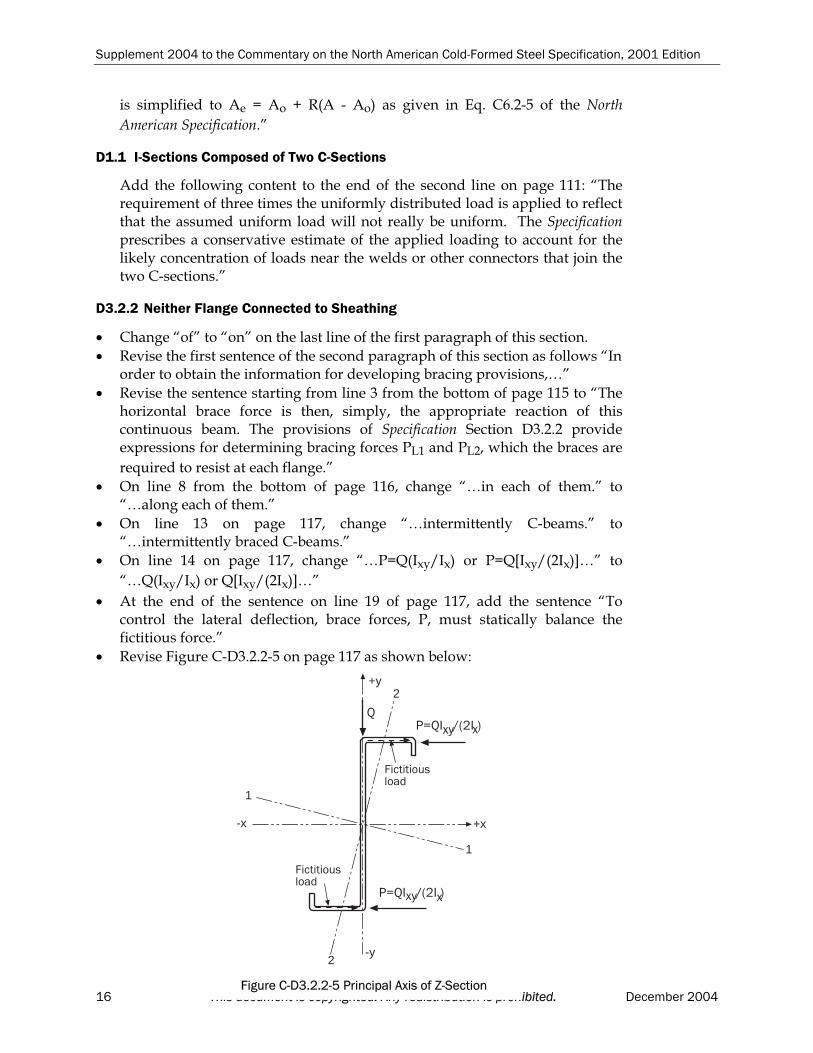
Supplement 2004 to the Commentary on the North American Cold-Formed Steel Specification, 2001 Edition
is simplified to Ae = Ao + R(A - Ao) as given in Eq. C6.2-5 of the North
American Specification.”
D1.1 I-Sections Composed of Two C-Sections
Add the following content to the end of the second line on page 111: “The requirement of three times the uniformly distributed load is applied to reflectthat the assumed uniform load will not really be uniform. The Specificationprescribes a conservative estimate of the applied loading to account for thelikely concentration of loads near the welds or other connectors that join the two C-sections.”
D3.2.2 Neither Flange Connected to Sheathing
Change “of” to “on” on the last line of the first paragraph of this section.
Revise the first sentence of the second paragraph of this section as follows “Inorder to obtain the information for developing bracing provisions,…”
Revise the sentence starting from line 3 from the bottom of page 115 to “Thehorizontal brace force is then, simply, the appropriate reaction of this continuous beam. The provisions of Specification Section D3.2.2 provideexpressions for determining bracing forces PL1 and PL2, which the braces are
required to resist at each flange.”
On line 8 from the bottom of page 116, change “…in each of them.” to“…along each of them.”
On line 13 on page 117, change “…intermittently C-beams.” to“…intermittently braced C-beams.”
On line 14 on page 117, change “…P=Q(Ixy/Ix) or P=Q[Ixy/(2Ix)]…” to
“…Q(Ixy/Ix) or Q[Ixy/(2Ix)]…”
At the end of the sentence on line 19 of page 117, add the sentence “To control the lateral deflection, brace forces, P, must statically balance the fictitious force.”
Revise Figure C-D3.2.2-5 on page 117 as shown below:
16 This document is copyrighted. Any redistribution is prohibited. December 2004
-x +x
1
1
2
2
+y
-y
2
�������������
�������������
)*2����3���� �' �
)*2����3���� �' �
Figure C-D3.2.2-5 Principal Axis of Z-Section
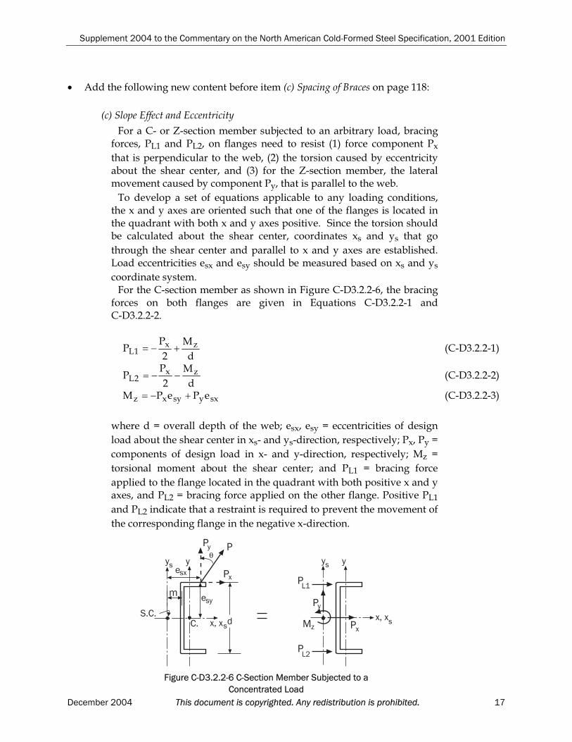
Supplement 2004 to the Commentary on the North American Cold-Formed Steel Specification, 2001 Edition
Add the following new content before item (c) Spacing of Braces on page 118:
(c) Slope Effect and Eccentricity
For a C- or Z-section member subjected to an arbitrary load, bracing forces, PL1 and PL2, on flanges need to resist (1) force component Px
that is perpendicular to the web, (2) the torsion caused by eccentricityabout the shear center, and (3) for the Z-section member, the lateral movement caused by component Py, that is parallel to the web.
To develop a set of equations applicable to any loading conditions,the x and y axes are oriented such that one of the flanges is located in the quadrant with both x and y axes positive. Since the torsion should be calculated about the shear center, coordinates xs and ys that go
through the shear center and parallel to x and y axes are established.Load eccentricities esx and esy should be measured based on xs and ys
coordinate system.For the C-section member as shown in Figure C-D3.2.2-6, the bracing
forces on both flanges are given in Equations C-D3.2.2-1 and C-D3.2.2-2.
d
M
2
PP zx
1L (C-D3.2.2-1)
d
M
2
PP zx
2L (C-D3.2.2-2)
sxysyxz ePePM (C-D3.2.2-3)
where d = overall depth of the web; esx, esy = eccentricities of design
load about the shear center in xs- and ys-direction, respectively; Px, Py =
components of design load in x- and y-direction, respectively; Mz =
torsional moment about the shear center; and PL1 = bracing force
applied to the flange located in the quadrant with both positive x and yaxes, and PL2 = bracing force applied on the other flange. Positive PL1
and PL2 indicate that a restraint is required to prevent the movement of
the corresponding flange in the negative x-direction.
December 2004 This document is copyrighted. Any redistribution is prohibited. 17
�
$%�%
)
�
)
)
)
)
)
�
'θ
' '
�(��
��
��
'
' '
�(��)�45
�
'
�%
Figure C-D3.2.2-6 C-Section Member Subjected to a Concentrated Load
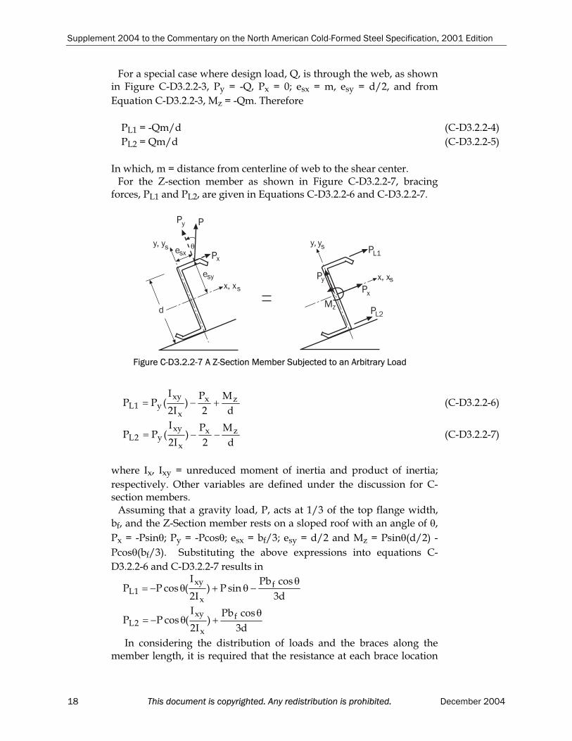
Supplement 2004 to the Commentary on the North American Cold-Formed Steel Specification, 2001 Edition
For a special case where design load, Q, is through the web, as shown in Figure C-D3.2.2-3, Py = -Q, Px = 0; esx = m, esy = d/2, and from
Equation C-D3.2.2-3, Mz = -Qm. Therefore
PL1 = -Qm/d (C-D3.2.2-4)
PL2 = Qm/d (C-D3.2.2-5)
In which, m = distance from centerline of web to the shear center. For the Z-section member as shown in Figure C-D3.2.2-7, bracing
forces, PL1 and PL2, are given in Equations C-D3.2.2-6 and C-D3.2.2-7.
d
M
2
P)
I2
I(PP zx
x
xyy1L (C-D3.2.2-6)
d
M
2
P)
I2
I(PP zx
x
xyy2L (C-D3.2.2-7)
where Ix, Ixy = unreduced moment of inertia and product of inertia;
respectively. Other variables are defined under the discussion for C-section members.
Assuming that a gravity load, P, acts at 1/3 of the top flange width,
bf, and the Z-Section member rests on a sloped roof with an angle of ,
Px = -Psin ; Py = -Pcos ; esx = bf/3; esy = d/2 and Mz = Psin (d/2) -
Pcos (bf/3). Substituting the above expressions into equations C-
D3.2.2-6 and C-D3.2.2-7 results in
d3
cosPbsinP)
I2
I(cosPP f
x
xy1L
d3
cosPb)
I2
I(cosPP f
x
xy2L
In considering the distribution of loads and the braces along the member length, it is required that the resistance at each brace location
)
�
)
)
)
)
)
�
'
θ'(�'
�(��
��
��
'
''(
�(��)�
45
�
'
Figure C-D3.2.2-7 A Z-Section Member Subjected to an Arbitrary Load
18 This document is copyrighted. Any redistribution is prohibited. December 2004
Supplement 2004 to the Commentary on the North American Cold-Formed Steel Specification, 2001 Edition
along the member length be greater than or equal to the design load within a distance of 0.5a on each side of the brace for distributed loads. For concentrated loads, the resistance at each brace location should begreater than or equal to the concentrated design load within a distance0.3a each side of the brace, plus 1.4(1-l/a) times each design load located farther than 0.3a but not farther than 1.0a from the brace. In theabove, a is the distance between centerline of braces along the member length and l is the distance from concentrated load to the brace to beconsidered.
Change “(c) Spacing of Braces” to “(d) Spacing of Braces”.
D4 Wall Studs and Wall Stud Assemblies
Delete the last sentence of the last paragraph of the section.
Add a new paragraph to the end of the section as follows:
In 2004 the sheathing braced design provisions were removed from the Specification and a requirement added that sheathing braced design be based on appropriate theory, tests, or rational engineering analysis that can be found in AISI, 2004; Green, Winter, and Cuykendall, 1947; Simaan, 1973; and Simaan andPekoz, 1976.
Replace Section D4.1 with the following:
D4.1 All Steel Design
The approach of determining effective areas in accordance with Specification Section D4.1 is currently being used in the RMI Specification (RackManufacturers Institute, 1997) for the design of perforated rack columns andwas verified extensively for such structures as reported by Pekoz (1988a). Thevalidity of this approach for wall studs was verified in a Cornell Universityproject on wall studs reported by Miller and Pekoz (1989 and 1994).
The limitations included in Specification Section D4.1 for the size andspacing of perforations and the depth of studs are based on the parameters used in the test program. For sections with perforations which do not meet these limits, the effective area, Ae, can be determined by stub column tests.
In the Specification, the web is defined as the component element of the section perpendicular to the wall and the flange is parallel to the plane of the wall.
Delete Sections D4.2 and D4.3.
D5 Floor, Roof or Wall Steel Diaphragm Construction
Replace the second, third and fourth paragraphs of the section with the followings:
December 2004 This document is copyrighted. Any redistribution is prohibited. 19
Supplement 2004 to the Commentary on the North American Cold-Formed Steel Specification, 2001 Edition
The structural performance of a diaphragm construction can be evaluated by either calculations or tests. Several analytical procedures exist, and are summarized in the literature (Steel Deck Institute, 1987; Department of Army, 1992; and ECCS, 1977). Analytical methods depend on the capacity of the connections between the panels and structural supports. The support thicknessand mechanical properties must be considered. As an example, the tilting potential of screws is discussed in Section E4.3 and is distinct from the bearing
capacity controlled by panels. When using analytical methods, refer to the
applicability limits. Tested performance is measured using the procedures of the Standard Method for Static Load Testing of Framed Floor, Roof and Wall Diaphragm Construction for Buildings, ASTM E455. Part VI of the AISI DesignManual (AISI, 2002) contains the Test Procedure with Commentary on CantileverTest Method for Cold-Formed Diaphragms. Yu (2000) provides a general discussion of structural diaphragm behavior.
The factors of safety and resistance factors listed in the Specification are basedon a recalibration of the full-scale test data summarized in the Steel Deck Institute Diaphragm Design Manual, First Edition. The recalibration used the method of Section A5.1.1 and F1.1 and the load factors in ASCE 7-98. The mostprobable diaphragm D/L load ratio is zero and this was used in therecalibration. The dominant diaphragm limit state is connection related.
Consistent with Commentary Section A 5.1.1(b), the calibration used 0 = 3.5 for
all load effects except wind load. The US LRFD method allows 0 = 2.5 for
connections subjected to wind loads. For both welds and screws calibration using
2.5 suggests factors less severe than = 0.8 and = 2.0. Because of concerns overweld quality control and to avoid significant departures from the SDI historically
accepted values and the previous edition's Table D5, = 0.70 and = 2.35 wereconservatively selected for wind loads. These values more closely equate to a
calibration using 0 3.0. Since diaphragm stiffness is typically determined from
the test data at 0.4 times the nominal load, this selection also avoids inconsistencies between strength and stiffness service determinations.
Consistent with confidence in construction quality control and the test data,the recalibration provides a distinction between screw fasteners and weldedconnections for load combinations not involving wind loading. The calibration ofresistance to seismic loads is based on a load factor of 1.6 and is consistent withAISC. The factor of safety for welded diaphragms subjected to earthquakeloading is slightly larger than those for other loading types. That factor is also slightly larger than the recalibration suggested. The increase is due to the greater toughness demands required by seismic loading, uncertainty over loadmagnitudes, and concern over weld quality control. When the load factor for earthquake loading is one, the 0.7 multiplier of ASCE 7 - 98 is allowed in ASDand the safety factors of Table D5 apply. If a local code requires a seismic loadfactor of 1.6, the factors of Table D5 still apply.
The Steel Deck Institute (1987) and the Department of Army (1992) haveconsistently recommended a safety factor of two to limit “out of plane buckling”of diaphragms. Out of plane buckling is related to panel profile, while the other
20 This document is copyrighted. Any redistribution is prohibited. December 2004
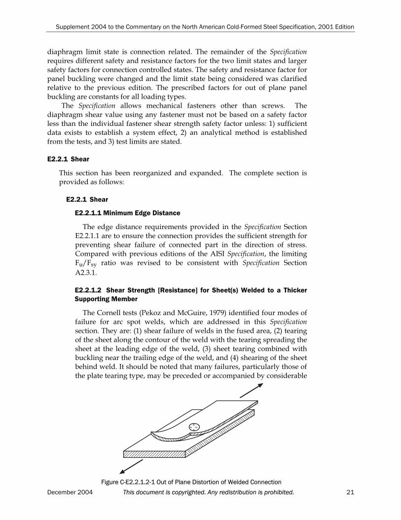
Supplement 2004 to the Commentary on the North American Cold-Formed Steel Specification, 2001 Edition
diaphragm limit state is connection related. The remainder of the Specificationrequires different safety and resistance factors for the two limit states and larger safety factors for connection controlled states. The safety and resistance factor for panel buckling were changed and the limit state being considered was clarified relative to the previous edition. The prescribed factors for out of plane panel buckling are constants for all loading types.
The Specification allows mechanical fasteners other than screws. Thediaphragm shear value using any fastener must not be based on a safety factorless than the individual fastener shear strength safety factor unless: 1) sufficientdata exists to establish a system effect, 2) an analytical method is established from the tests, and 3) test limits are stated.
E2.2.1 Shear
This section has been reorganized and expanded. The complete section is provided as follows:
E2.2.1 Shear
E2.2.1.1 Minimum Edge Distance
The edge distance requirements provided in the Specification SectionE2.2.1.1 are to ensure the connection provides the sufficient strength for preventing shear failure of connected part in the direction of stress. Compared with previous editions of the AISI Specification, the limiting Fu/Fsy ratio was revised to be consistent with Specification Section
A2.3.1.
E2.2.1.2 Shear Strength [Resistance] for Sheet(s) Welded to a ThickerSupporting Member
The Cornell tests (Pekoz and McGuire, 1979) identified four modes offailure for arc spot welds, which are addressed in this Specificationsection. They are: (1) shear failure of welds in the fused area, (2) tearing of the sheet along the contour of the weld with the tearing spreading the sheet at the leading edge of the weld, (3) sheet tearing combined withbuckling near the trailing edge of the weld, and (4) shearing of the sheet behind weld. It should be noted that many failures, particularly those ofthe plate tearing type, may be preceded or accompanied by considerable
December 2004 This document is copyrighted. Any redistribution is prohibited. 21
Figure C-E2.2.1.2-1 Out of Plane Distortion of Welded Connection

Supplement 2004 to the Commentary on the North American Cold-Formed Steel Specification, 2001 Edition
inelastic out-of-plane deformation of the type indicated in Figure C-E2.2.1.2-1. This form of behavior is similar to that observed in wide, pin-connected plates. Such behavior should be avoided by closer spacing ofwelds. When arc spot welds are used to connect two sheets to a framing member as shown in Specification Figure E2.2.1.1-2, consideration should also be given to the possible shear failure between thin sheets.
The thickness limitation of 0.15 inch (3.81 mm) is due to the range ofthe test program that served as the basis of these provisions. On sheetsbelow 0.028 inch (0.711 mm) thick, weld washers are required to avoidexcessive burning of the sheets and, therefore, inferior quality welds.
In the AISI 1996 Specification, Equation E2.2.1.2-1 was revised to be consistent with the research report (Pekoz and McGuire, 1979).
In 2001, the equation used for determining da for multiple sheets was
revised to be (d-t).
E2.2.1.3 Shear Strength [Resistance] for Sheet to Sheet Connections
The Steel Deck Institute Design Manual (SDI, 1987) stipulates that theshear strength for a sheet-to-sheet arc spot weld connection be taken as75% of the strength of a sheet-to-structural connection. SDI further stipulates that the sheet-to-structural connection strength [resistance] bedefined by Specification Equation E2.2.1.2-2. This design provision was adopted by the Specification in 2004. Prior to accepting the SDI designrecommendation, a review of the pertinent research by Luttrell (SDI,1987) was performed by LaBoube (LaBoube, 2001). The test datathickness range that is reflected in the Specification documents the scope of Luttrell’s test program. SDI suggests that sheet-to-sheet welds are problematic for thickness less than 0.0295 in. (0.75 mm). Such weldsresult in “blow holes” but the perimeter must be fused to be effective.
Quality control for sheet–to-sheet connections is not within the purview of AWS D1.3. However, using AWS D1.3 as a guide, the following quality control/assurance guidelines are suggested:(1) Measure the visible diameter of the weld face, (2) Ensure no cracks in the welds,(3) Maximum undercut = 1/8 of the weld circumference, and (4) Sheets are to be in contact with each other.
E4 Screw Connections
Revise the last sentence of the first paragraph in the section to “A higherdegree of accuracy can be obtained by testing any particular connectiongeometry (AISI, 1992).”
E4.3.3 Shear in Screws
Revise the last sentence to “In order to prevent the brittle and sudden shear fracture of the screw, the Specification applies a 25 percent adjustment to thefactor of safety or the resistance factor where determined in accordance with
22 This document is copyrighted. Any redistribution is prohibited. December 2004

Supplement 2004 to the Commentary on the North American Cold-Formed Steel Specification, 2001 Edition
Section F1.”
E4.4.3 Tension in Screws
Revise the last sentence to “In order to prevent the brittle and sudden tensilefracture of the screw, the Specification applies a 25 percent adjustment to thefactor of safety or the resistance factor where determined in accordance with Section F1.”
E4.5 Combined Shear and Pull-Over
Add the following new section:
E4.5 Combined Shear and Pull-Over
Research pertaining to the behavior of a screw connection has beenconducted at West Virginia University (Luttrell, 1999). Based on a review andanalysis of West Virginia University’s data for the behavior of a screwconnection subject to combined shear and tension (Zwick and LaBoube, 2002),equations were derived that enable the evaluation of the strength of a screwconnection when subjected to combined shear and tension. The tests indicatedthat at failure the sheet beneath the screw head pulled over the head of thescrew or the washer. Therefore, the nominal tensile strength is based solely on Pnov. Although both non-linear and linear equations were developed, for
ease of computation and because the linear equation provides regions of Q/Pns and T/Pnov equal to unity, the linear equation was adopted for the
Specification. The proposed equation is based on the following test programlimits:
0.0285 in. (0.724 mm) t1 0.0445 in. (1.13 mm)
No. 12 and No. 14 self-drilling screws with or without washers
dw 0.75 in. (19.1 mm)
62 ksi (427 MPa or 4360 kg/cm2) Fu1 70.7 ksi (487 MPa or 4970 kg/cm2)
t2 / t1 2.5
The limit t2 / t1 2.5 reflects the fact that the test program (Luttrell,
1999) focused on connections having sheet thicknesses that precluded the tilting limit state from occurring. Thus, this limit ensures that the design equations will only be used when tilting limit state does not the control limitstate.
The linear form of the equation as adopted by the Specification is similar to the following more conservative linear design equation that has been used by engineers:
Q/Pns + T/Pnov 1.0
An eccentric load on a connection may create a non-uniform stress distribution around the fastener. For example, tension tests on roof panel connections have shown that under an eccentrically applied tension force the resulting connection capacity is 50% of the tension capacity under a uniformly applied tension force. Thus, the Specification stipulates that the pull-over
December 2004 This document is copyrighted. Any redistribution is prohibited. 23

Supplement 2004 to the Commentary on the North American Cold-Formed Steel Specification, 2001 Edition
strength shall be taken as 50% of Pnov. If the eccentric load is applied by a
rigid member such as a clip, the resulting tension force on the screw may be uniform, thus the force in the screw can be determined by mechanics and thecapacity of the fastener should be reliably estimated by Pnov.
F1.1 Load and Resistance Factor Design and Limit States Design
Add the following paragraph to the end of the section:
In 2004, the statistic data VM for screw bearing strength was revised
from 0.10 to 0.08. This revision is based on the tensile strength statistic dataprovided in the UMR research report (Rang and Galambos, 1979b). In addition, Vf was revised from 0.10 to 0.05 to reflect the tolerance of the cross-
sectional area of the screw.
F3.1 Full Section
On the second line to the end of the section, change “Part VIII” to “Part VI”.
G. DESIGN OF COLD-FORMED STEEL STRUCTURAL MEMBERS AND CONNECTIONS FOR CYCLIC LOADING (FATIGUE)
In the second paragraph on page 143 of the Commentary, a reference of “(LaBoube and Yu, 1999)” is added to the end of the first sentence.
REFERENCES
On lines 9 and 10 from top of page 159, change “(1988)” to “1987”.
Add the following references:
American Iron and Steel Institute (2004), Standard for Cold-Formed Steel Framing – Wall Stud Design, Washington, D. C., 2004.
Bambach, M. R., and K. J. R. Rasmussen (2002a), "Tests on UnstiffenedElements under Combined Bending and Compression," Research ReportR818, Department of Civil Engineering, University of Sydney, Australia,May 2002.
Bambach, M. R., and K. J. R. Rasmussen, (2002b) "Elastic and Plastic Effective Width Equations for Unstiffened Elements," Research ReportR819, Department of Civil Engineering, University of Sydney, Australia,2002.
Bambach, M. R., and K. J. R. Rasmussen (2002c), "Design Models for Thin-Walled Sections in Bending containing Unstiffened Elements," ResearchReport R820, Department of Civil Engineering, University of Sydney, Australia, 2002.
Bryant, M.R. and T. M. Murray (2001) “Investigation of Inflection Pointsas Brace Points in Multi-Span Purlin Roof Systems,” Report No. CE/VPI-ST 99/08, Virginia Polytechnic Institute and State University, VA, 2001.
24 This document is copyrighted. Any redistribution is prohibited. December 2004
Supplement 2004 to the Commentary on the North American Cold-Formed Steel Specification, 2001 Edition
Fox, S.R. and R. M. Schuster (2002), “Bearing Stiffeners in Cold-FormedSteel C-Sections,” Final Report, American Iron and Steel Institute, Washington, D.C., 2002.
Fox, S.R. (2002), “Bearing Stiffeners in Cold Formed Steel C-Sections,”Ph.D. Thesis, Department of Civil Engineering, University of Waterloo, Waterloo, Ontario, Canada, 2002.
Joint Departments of the Army, Navy, Air Force, USA (1992), Chapter 13,Seismic Design for Buildings, TM 5-809-10/NAVFACP-355/AFM 88-3,Washington, D.C., 20 October 1992.
Kulak, G.L., and G.Y. Grondin, (2001), “AISC LRFD Rules for Block Shearin Bolted Connections – A Review,” Engineering Journal, Fourth Quarter,2001, American Institute of Steel Construction, IL, 2001.
LaBoube, R. A. (2001), “Arc Spot Welds in Sheet-to-Sheet Connections,”Department of Civil Engineering, University of Missouri-Rolla, MO, 2001.
LaBoube and M.A. Sokol (2002), “Behavior of Screw Connections inResidential Construction,” Journal of Structural Engineering, ASCE, Vol.128, No. 1, January 2002.
LaBoube, R. A., R.M. Schuster and J. Wallace (2002), “Web Crippling and Bending Interaction of Cold-Formed Steel Members,” Final Report, University of Waterloo, Canada, 2002.
Luttrell, L.D. (1999), “Metal Construction Association Diaphragm TestProgram,” West Virginia University, WV, 1999.
Stolarczyk, J. A., J. M. Fisher and A. Ghorbanpoor (2002), “Axial Strengthof Purlins Attached to Standing Seam Roof Panels,” Proceedings of theSixteenth International Specialty Conference on Cold-Formed Steel Structures,University of Missouri-Rolla, MO, October 2002.
Wallace, A.W (2003), "Web Crippling of Cold-Formed Steel Multi-Web Deck Sections Subjected to End One-flange Loading," Final Report,Canadian Cold Formed Steel Research Group, Department of CivilEngineering, University of Waterloo, Waterloo, Ontario, Canada, May 2003.
Yang, D. and G. J. Hancock (2003), “Compression Tests of Cold-Reduced High Strength Steel Channel Columns Failing in the Distortional Mode.” University of Sydney, Department of Civil Engineering, Research ReportR825, Australia.
Yiu, F., and T. Pekoz (2001), "Design of Cold-Formed Steel PlainChannels. Final Report," Cornell University, Ithaca, NY, 2001.
Young, B. and G.J. Hancock (2000), “Experimental Investigation of Cold-Formed Channels Subjected to Combined Bending and Web Crippling,”Proceedings of the Fifteenth International Specialty Conference on Cold-FormedSteel Structures, University of Missouri-Rolla, MO, 2000.
Zwick, K. and R. A. LaBoube (2002), “Self-Drilling Screw Connections Subject to Combined Shear and Tension,” Wei-Wen Yu Center for Cold-Formed Steel Structures, University of Missouri-Rolla, MO, 2002.
December 2004 This document is copyrighted. Any redistribution is prohibited. 25
Supplement 2004 to the Commentary on the North American Cold-Formed Steel Specification, 2001 Edition
CHANGES AND UPDATES IN APPENDICES A AND C
A2.2 Other Steels
Replace the whole section with the following:
A2.2 Other Steels
Although the use of ASTM-designated steels listed in SpecificationSection A2.1 is encouraged, other steels may also be used in cold-formed steelstructures, provided they satisfy the requirements stipulated in this provision.
In 2004, these requirements were clarified and revised. The Specificationhas long required that such “other steels” conform to the chemical and mechanical requirements of one of the listed specifications or “other published specification.” Specific requirements for a published specificationhave been detailed in the definitions under General Terms, A1.2. It is important to note that, by this definition, published requirements must beestablished before the steel is ordered, not by a post-order screening process. The requirements must include minimum tensile properties, chemical composition limits, and for coated sheets, coating properties. Testingprocedures must be in accord with the referenced ASTM specifications. A proprietary specification of a manufacturer, purchaser, or producer couldqualify as a published specification if it meets the definition requirements.
As an example of these Specification provisions, it would not bepermissible to establish a minimum yield point or minimum tensile strength,greater than that ordered to a standard ASTM grade, by reviewing mill testreports or conducting additional tests. However, it would be permissible to publish a manufacturer’s or producer’s specification before the steel is ordered requiring that such enhanced properties be furnished as a minimum. Testing to verify that the minimum properties are achieved could be done by the manufacturer or the producer. The intent of these provisions is to ensurethat the material factor Mm (see Chapter F) will be maintained at about 1.10,
corresponding to an assumed typical 10 percent overrun in tensile properties for ASTM grades.
Special additional requirements have been added to qualifyunidentified material. In such a case, the manufacturer must run tensile testssufficient to establish that the yield point and tensile strength of each mastercoil are at least 10 percent greater than the applicable published specification.As used here, master coil refers to the coil being processed by the manufacturer. Of course, the testing must always be adequate to ensure thatspecified minimum properties are met, as well as the ductility requirements of A2.3.
Where the material is used for fabrication by welding, care must beexercised in selection of chemical composition or mechanical properties to ensure compatibility with the welding process and its potential effect on altering the tensile properties.
26 This document is copyrighted. Any redistribution is prohibited. December 2004
Supplement 2004 to the Commentary on the North American Cold-Formed Steel Specification, 2001 Edition
C3.1.4 Beam Having One Flange Fastened to a Standing Seam Roof System
Revise the second to the last sentence of the section to “In SpecificationEquation C3.1.4-1, the reduction factor, R, can be determined by AISI TS-6-04published by AISI (AISI, 2004).
C4.7 Compression of Z-Section Members Having One Flange Fastened to aStanding Seam Roof
Add the following new section:
C4.7 Compression of Z-Section Members Having One Flange Fastened to aStanding Seam Roof
The strength of axially loaded Z-sections having one flange attached tostanding seam roof may be limited by either a combination of torsional buckling and lateral buckling in the plane of the roof, or by flexural bucklingin a plane perpendicular to the roof. As in the case of Z-sections carryinggravity or wind loads as beams, the roof diaphragm and purlin clips provide a degree of torsional and lateral bracing restraint that is significant, but notnecessarily sufficient, to develop the full strength of the cross section.
Specification Equation C4.7-1 predicts the lateral buckling strength using an ultimate axial buckling stress (kafRFy) that is a percentage of the ultimate
flexural stress (RFy) determined from uplift tests performed using AISI TS-8,
Base Test Method for Purlins Supporting a Standing Seam Roof System, aspublished by AISI. This equation, developed by Stolarczyk (2002), wasderived empirically from elastic finite element buckling studies and calibratedto the results of a series of tests comparing flexural and axial strengths usingthe uplift “Base Test” setup. The gross area, A, has been used rather than the effective area, Ae, because the ultimate axial stress is generally not large
enough to result in a significant reduction in the effective area for common cross section geometries.
Equation C4.7-1 may be used with the results of uplift “Base Tests”conducted with and without discreet point bracing. There is no limitation on the minimum length because Equation C4.7-1 is conservative for spans that are smaller than that tested under the “Base Test” provisions.
The strength of longer members may be governed by axial bucklingperpendicular to the roof; consequently, the provisions of Section C4 and C4.1should also be checked for buckling about the strong axis.
E2a Welded Connections
Add the following as the first paragraph of the section:
The upper limit of the Specification applicability was revised in 2004 from 0.18 in. (4.57 mm) to 3/16 in. (4.76 mm). This change was made to be consistent with the limit given in the AWS D1.3 (1998).
Change “0.18 in. (4.57 mm)” to “3/16 in. (4.76 mm)” in the last paragraph.
December 2004 This document is copyrighted. Any redistribution is prohibited. 27
Supplement 2004 to the Commentary on the North American Cold-Formed Steel Specification, 2001 Edition
E3a Bolted Connections
Add the following content to the end of the last paragraph: “An exception to the provisions for slotted holes is made in the case of slotted holes in lapped and nested zees. Resistance is provided in this situation partially by thenested components, rather than direct bolt shear and bearing. An oversize or slotted hole is required for proper fit-up due to offsets inherent in nested parts. Recent research (Bryant and Murray, 2001) has shown that lapped andnested zee members with 1/2 in. (12.7 mm) diameter bolts without washers and 9/16 in. x 7/8 in. (14.3 mm x 22.2 mm) slotted holes in the direction of stress can develop the full moment in the lap.”
E5 Rupture
Add the following as a new paragraph to the end of the section:
The summary paper “AISC LRFD Rules for Block Shear in BoltedConnections – A Review” (Kulak and Grondin, 2001) provides a summary of test data for block shear rupture strength. In 2004, Equations E5.3-1 and E5.3-2 were adopted for the limit state of block shear rupture for bolted cold-formed steel connections because eccentricity in cold-formed steel sections is usually small. In theory provisions for block shear could also be applied to screw connections.However, because the final placement location of self-drilling screws cannot be assured, a block shear check is of little significance. Also, tests performed at theUniversity of Missouri-Rolla have indicated that the current design equations for shear and tilting provide a reasonably good estimate of the connection performance for multiple screws in a pattern (LaBoube and Sokol, 2002).
28 This document is copyrighted. Any redistribution is prohibited. December 2004
Supplement 2004 to the Commentary on the North American Cold-Formed Steel Specification, 2001 Edition
CHANGES AND UPDATES IN APPENDIX B
A2.4a Delivered Minimum Thickness
Delete the entire section.
A3 Loads
Add the following as a new section:
A3 Loads
The load provisions contained in Appendix B of CSA S136-01 were changed to be compatible with the changes to be incorporated in Part 4 of theNational Building Code of Canada (NBC) 2005. This entails the following:(1) The version of Limit States Design to appear in NBC 2005 is based on the
companion action format, which is being adopted world-wide and is amore rational method of combining loads than the previous version.
(2) NBC 1995 distinguished wind load for different categories of buildingsusing a return period approach, an increase in design loads for earthquake based on building use by means of an importance factor, and made no allowance for different snow loads based on the occupancy of the structure. It was decided to harmonize the approach used, and so the importance factor methodology was chosen for snow, wind andearthquake loads.
C2.2 Fracture of Net Section
Add the following paragraph to the end of the section:
The provision regarding block tear-out of Section C2.2 was rewritten in accordance with the latest research by Kulak and Grondin (2001). A new section on coped beams was also added as per the recommendations by theseauthors. Based on the actual test data, an additional correction was made by only applying the 0.9 factor to the direct tension and stagger failure paths. In CSA S136-01, the 0.9 factor was also applied to the shear failure path.
COMMENTARY ON APPENDIX 1, DESIGN OF COLD-FORMED STEEL STRUCTURALMEMBERS USING THE DIRECT STRENGTH METHOD
The following commentary is newly added.
December 2004 This document is copyrighted. Any redistribution is prohibited. 29

Supplement to Commentary on 2001 North American Cold-Formed Steel Specification – Appendix 1
Commentary on Appendix 1
Design of Cold-Formed Steel
Structural Members
Using the Direct Strength Method
2004 EDITION


Supplement 2004 to the Commentary on the 2001 North American Cold-Formed Steel Specification –Appendix 1
TABLE OF CONTENTS
COMMENTARY ON APPENDIX 1 DESIGN OF COLD-FORMED STEEL STRUCTURAL MEMBERS
USING THE DIRECT STRENGTH METHOD2004 EDITION
1.1 GENERAL PROVISIONS ............................................................................................................. 1-31.1.1 Applicability ..........................................................................................................................1-3
1.1.1.1 Pre-qualified Columns........................................................................................ 1-3
1.1.1.2 Pre-qualified Beams ........................................................................................... 1-41.1.2 Elastic Buckling .....................................................................................................................1-4
1.1.2.1 Elastic Buckling - Numerical Solutions ........................................................... 1-101.1.2.1.1 Local Buckling via Finite Strip (Pcr , Mcr )..............................................1-11
1.1.2.1.2 Distortional Buckling via Finite Strip (Pcrd, Mcrd) .................................1-12
1.1.2.1.3 Global (Euler) Buckling via Finite Strip (Pcre, Mcre) ..............................1-12
1.1.2.2 Elastic Buckling – Manual Solutions ............................................................... 1-131.1.3 Serviceability Determination.............................................................................................1-15
1.2 MEMBERS ............................................................................................................................... 1-151.2.1 Column Design....................................................................................................................1-15
1.2.1.1 Flexural, Torsional, or Torsional-Flexural Buckling ....................................... 1-18
1.2.1.2 Local Buckling ................................................................................................. 1-18
1.2.1.3 Distortional Buckling ....................................................................................... 1-181.2.2 Beam Design ........................................................................................................................1-18
1.2.2.1 Lateral-Torsional Buckling .............................................................................. 1-21
1.2.2.2 Local Buckling ................................................................................................. 1-21
1.2.2.3 Distortional Buckling ....................................................................................... 1-21
REFERENCES...................................................................................................................................... 1-21
Appendix A1-2 This document is copyrighted. Any redistribution is prohibited. December 2004
Supplement 2004 to the Commentary on the 2001 North American Cold-Formed Steel Specification –Appendix 1
1.1 GENERAL PROVISIONS
1.1.1 Applicability
The Direct Strength Method of Appendix 1 is an alternative procedure for determining the strength [resistance] and stiffness of cold-formed steel members(beams and columns). The reliability of Appendix 1 is insured by using
calibrated safety factor, and resistance factor, within set geometric limits,
and conservative and for other configurations. The applicability of Appendix 1 to all beams and columns implies that in some situations competing methods may exist for strength determination of a member: the main Specification andAppendix 1. In this situation there is no preferred method. Either method may be used to determine the strength [resistance]. The fact that one method may give a greater or lower strength [resistance] prediction in a given situation does not
imply an increased accuracy for either method. The and factors are designedto insure that both methods reach their target reliability.
The method of Appendix 1 provides solutions for beams and columns only, but these solutions must be combined with the regular provisions of the main Specification to cover other cases: shear, beam-columns, etc. For example, an application to purlin design was completed using the provisions of this Appendix for the bending strength, and then those calculations were augmentedby shear, and shear and bending interaction calculations, in line with the main Specification (Quispe and Hancock, 2002). Further, beam-columns may beconservatively examined using the provisions of the main Specification, by replacing the beam and column design strength [factored resistance] with theprovisions of this Appendix, or beam-columns may be analyzed using the actualstress state (Schafer, 2002b).
The pre-qualified columns and beams only include members without perforations (punchouts). Members with perforations generally may be designedby the main Specification. For perforated members not covered by the Specificationone may want to consider a rational analysis method which partially employsthe methods of this Appendix. The key issue in such a rational analysis is theaccurate determination of the elastic local, distortional, and global buckling loads (or moments) for the member with perforations. Numerical (e.g., finite element)analysis where the holes are explicitly considered is one option in this case.
Note:The North American Specification for the Design of Cold-Formed Steel Structural Members,
Chapters A through G and Appendices A through C, is herein referred to as the main
Specification.
1.1.1.1 Pre-qualified Columns
An extensive amount of testing has been performed on concentrically loaded, pin-ended, cold-formed steel columns (Kwon and Hancock, 1992; Lau and Hancock, 1987; Loughlan, 1979; Miller and Peköz, 1994; Mulligan, 1983; Polyzois et al., 1993; Thomasson, 1978). Data from these researchers were compiled and used for calibration of the Direct Strength Method. Thegeometric limitations listed in Appendix 1 are based on these experiments.
December 2004 This document is copyrighted. Any redistribution is prohibited. Appendix A1-3
Supplement 2004 to the Commentary on the 2001 North American Cold-Formed Steel Specification –Appendix 1
It is intended that as more cross-sections are verified for use in the Direct Strength Method, these tables and sections will be augmented.Companies with proprietary sections may wish to perform their own testing
and follow Chapter F of the main Specification to justify the use of lower and
higher factors for a particular cross-section. Alternatively, member geometries that are not pre-qualified may still use the method of Appendix 1,
but with the increased and reduced factors consistent with any rationalanalysis method as prescribed in A1.1 of the main Specification.
1.1.1.2 Pre-qualified Beams
An extensive amount of testing has been performed on laterally bracedbeams (Cohen, 1987; Ellifritt et al., 1997; LaBoube and Yu, 1978; Moreyara, 1993; Phung and Yu, 1978; Rogers, 1995; Schardt and Schrade, 1982; Schuster,1992; Shan et al., 1994; Willis and Wallace, 1990) and on hats and decks(Acharya and Schuster, 1998; Bernard, 1993; Desmond, 1977; Höglund, 1980;König, 1978; Papazian et al., 1994). Data from these researchers were compiled and used for calibration of the Direct Strength Method. The geometric limitations listed in the Appendix are based on the experiments performed by these researchers. Please see the note on pre-qualified columns for furthercommentary on members which do not meet the pre-qualified geometric limits.
Users of this Appendix should be aware that pre-qualified beams withlarge flat width-to-thickness ratios in the compression flange will beconservatively predicted by the method of this Appendix when compared to the main Specification (Schafer and Peköz, 1998). However, the same beam with small longitudinal stiffeners in the compression flange will be wellpredicted using this Appendix.
1.1.2 Elastic Buckling
The elastic buckling load is the load in which the equilibrium of the memberis neutral between two alternative states: buckled and straight. Thin-walled cold-formed steel members have at least 3 relevant elastic buckling modes: local, distortional, and global (Figure C-1.1.2-1). The global buckling mode includesflexural, torsional, or flexural-torsional buckling for columns, and lateral-torsional buckling for beams. Traditionally, the main Specification has onlyaddressed local and global buckling. Further, the main Specification’s approach to local buckling is to conceptualize the member as a collection of “elements” andinvestigate local buckling of each element separately.
The method of this Appendix provides a means to incorporate all three relevant buckling modes into the design process. Further, all buckling modes are determined for the member as a whole rather than element by element. Thisinsures that compatibility and equilibrium are maintained at element junctures.Consider, as an example, the lipped C-Section shown in pure compression inFigure C-1.1.2-1(a). The member’s local elastic buckling load from the analysis is:
Pcr = 0.12 x 48.42 kips = 5.81 kips (25.84 kN).
The column has a gross area (Ag) of 0.881 in2 (568.4 mm2), therefore,
Appendix A1-4 This document is copyrighted. Any redistribution is prohibited. December 2004
Supplement 2004 to the Commentary on the 2001 North American Cold-Formed Steel Specification –Appendix 1
fcr = Pcr /Ag = 6.59 ksi (45.44 MPa)
The main Specification determines a plate buckling coefficient, k, for each element, then fcr, and finally the effective width. The centerline dimensions
(ignoring corner radii) are h = 8.94 in. (227.1 mm), b = 2.44 in. (62.00 mm), d = 0.744 in. (18.88 mm), and t = 0.059 in. (1.499 mm), the critical buckling stress, fcr
of each element as determined from the main Specification:
lip: k = 0.43, fcr -lip= 0.43[ 2E/(12(1- 2))](t/d)2 = 72.1 ksi (497 MPa)
flange: k = 4, fcr -flange= 4.0[ 2E/(12(1- 2))](t/b)2 = 62.4 ksi (430 MPa)
web: k = 4, fcr -web= 4.0[ 2E/(12(1- 2))](t/h)2 = 4.6 ksi (32.0 MPa)
Each element predicts a different buckling stress, even though the member is a connected group. These differences in the buckling stress are ignored in themain Specification. The high flange and lip buckling stresses have little relevancegiven the low web buckling stress. The finite strip analysis, which includes the interaction amongst the elements, shows that the flange aids the web significantly in local buckling, increasing the web buckling stress from 4.6 ksi (32.0 MPa) to 6.59 ksi (45.4 MPa), but the buckling stress in the flange and lip are much reduced due to the same interaction. Comparisons to the distortionalbuckling stress (fcrd) using k from B4.2 of the main Specification do no better
(Schafer and Peköz, 1999; Schafer, 2002).The method of this Appendix allows rational analysis to be used for
determining the local, distortional and global buckling load or moment. Specific guidance on elastic buckling determination follows. Users are reminded that thestrength of a member is not equivalent to the elastic buckling load (or moment)of the member. In fact the elastic buckling load can be lower than the actual strength, for slender members with considerable post-buckling reserve; or the elastic buckling load can be fictitiously high due to ignoring inelastic effects. Nonetheless, the elastic buckling load is a useful reference load for determining a member’s slenderness and ultimately its strength.
Manual and numerical solutions for elastic buckling prediction are coveredin the following sections. It is permissible to mix the manual and numerical methods; in some cases it is even advantageous. For example, numericalsolutions for member local and distortional buckling are particularly convenient;
however, unusual long column bracing conditions (KL)x (KL)y (KL)t may
often be handled with less confusion using the traditional manual formulas. Use of the numerical solutions is generally encouraged, but verification with themanual solutions can aid in building confidence in the numerical solution.
December 2004 This document is copyrighted. Any redistribution is prohibited. Appendix A1-5

Supplement 2004 to the Commentary on the 2001 North American Cold-Formed Steel Specification –Appendix 1
100
101
102
103
0
0.5
1
1.5
half−wavelength (in.)
Mcr
/ M
y
AISI (2002) Ex. I−8
My=126.55kip−in.
Local Mcr
/My=0.67 Distortional M
cr/M
y=0.85
Lateral−torsional
100
101
102
103
0
0.05
0.1
0.15
0.2
0.25
0.3
0.35
0.4
half−wavelength (in.)
Pcr
/ P
y
AISI (2002) Ex. I−8
Py=48.42kips
Local Pcr
/Py=0.12 Distortional P
cr/P
y=0.26
Flexural
(a) 9CS2.5x059 of AISI 2002 Cold-Formed Steel Design Manual Example I-8
Figure C-1.1.2-1 Examples of Bending and Compression Elastic Buckling Analysiswith Finite Strip Method
Appendix A1-6 This document is copyrighted. Any redistribution is prohibited. December 2004
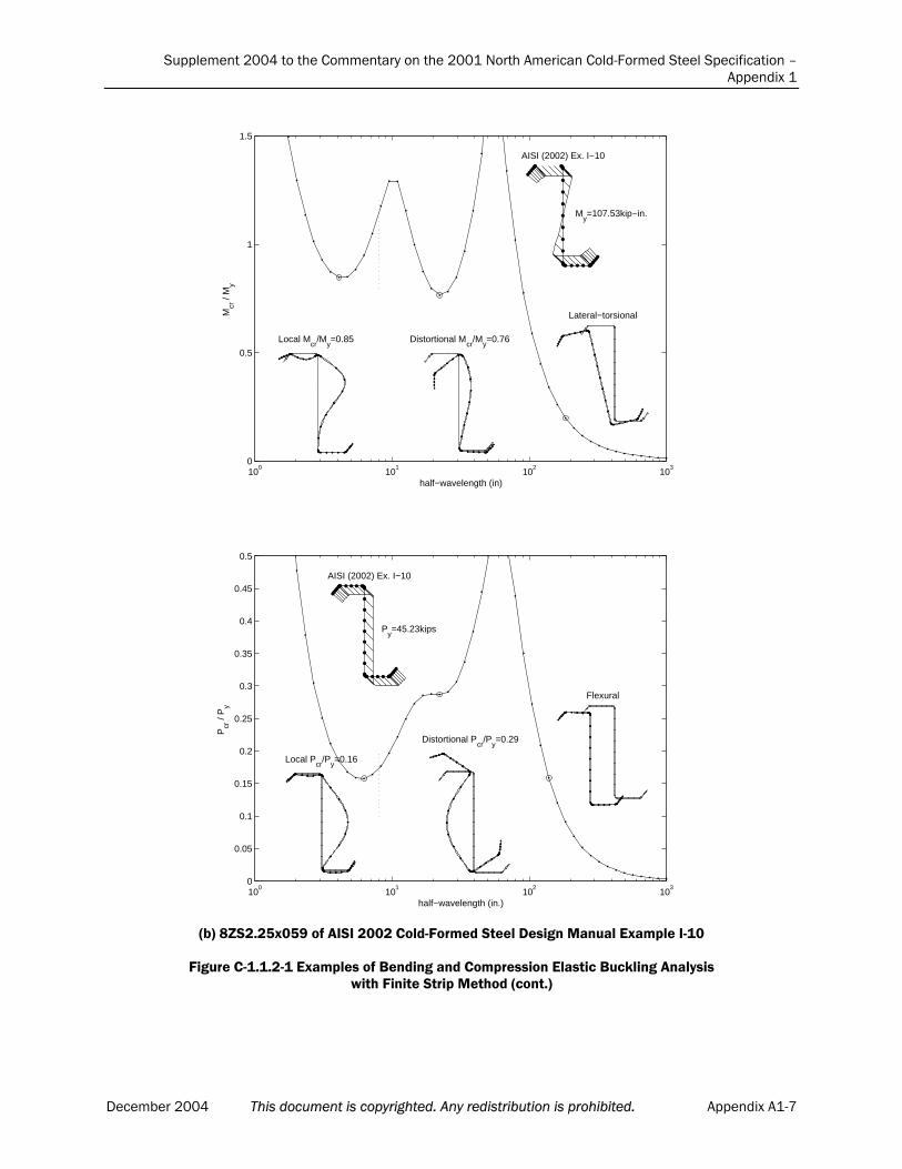
Supplement 2004 to the Commentary on the 2001 North American Cold-Formed Steel Specification –Appendix 1
100
101
102
103
0
0.5
1
1.5
half−wavelength (in)
Mcr
/ M
y
AISI (2002) Ex. I−10
My=107.53kip−in.
Local Mcr
/My=0.85 Distortional M
cr/M
y=0.76
Lateral−torsional
100
101
102
103
0
0.05
0.1
0.15
0.2
0.25
0.3
0.35
0.4
0.45
0.5
half−wavelength (in.)
Pcr
/ P
y
AISI (2002) Ex. I−10
Py=45.23kips
Local Pcr
/Py=0.16
Distortional Pcr
/Py=0.29
Flexural
(b) 8ZS2.25x059 of AISI 2002 Cold-Formed Steel Design Manual Example I-10
Figure C-1.1.2-1 Examples of Bending and Compression Elastic Buckling Analysiswith Finite Strip Method (cont.)
December 2004 This document is copyrighted. Any redistribution is prohibited. Appendix A1-7

Supplement 2004 to the Commentary on the 2001 North American Cold-Formed Steel Specification –Appendix 1
100
101
102
103
0
0.5
1
1.5
half−wavelength (in.)
Mcr
/ M
y
AISI (2002) Ex. I−12
My=2.12kip−in.
Distortional Mcr
/My=1.03
Lateral−torsional
100
101
102
103
0
0.5
1
1.5
2
2.5
3
3.5
half−wavelength (in.)
Mcr
/ M
y
AISI (2002) Ex. I−12
My=2.12kip−in.
Distortional Mcr
/My=2.18
Lateral−torsional
(c) 2LU2x060 of AISI 2002 Cold-Formed Steel Design Manual Example I-12
Figure C-1.1.2-1 Examples of Bending and Compression Elastic Buckling Analysiswith Finite Strip Method (cont.)
Appendix A1-8 This document is copyrighted. Any redistribution is prohibited. December 2004

Supplement 2004 to the Commentary on the 2001 North American Cold-Formed Steel Specification –Appendix 1
100
101
102
103
0
1
2
3
4
5
6
7
8
half−wavelength (in.)
Mcr
/ M
y
AISI (2002) Ex. I−13
My=79.09kip−in.
Local Mcr
/My=3.46
Lateral−torsional
100
101
102
103
0
0.5
1
1.5
2
2.5
3
3.5
4
4.5
5
half−wavelength (in.)
Pcr
/ P
y
AISI (2002) Ex. I−13
Py=86.82kips
Local Pcr
/Py=2.66
Flexural−torsional
(d) 3HU4.5x135 of AISI 2002 Cold-Formed Steel Design Manual Example I-13
Figure C-1.1.2-1 Examples of Bending and Compression Elastic Buckling Analysiswith Finite Strip Method (cont.)
December 2004 This document is copyrighted. Any redistribution is prohibited. Appendix A1-9
Supplement 2004 to the Commentary on the 2001 North American Cold-Formed Steel Specification –Appendix 1
1.1.2.1 Elastic Buckling - Numerical Solutions
A variety of numerical methods: finite element, finite differences, boundary element, generalized beam theory, finite strip analysis, and others, may provide accurate elastic buckling solutions for cold-formed steel beamsand columns.
Traditional finite element analysis using thin plate or shell elements may be used for elastic buckling prediction. Due to the common practice of using polynomial shape functions, the number of elements required for reasonable accuracy can be significant. Finite element analysis books such as Cook et al. (1989) and Zienkiewicz and Taylor (1989, 1991) explain the basic theory; while a number of commercial implementations can provide accurateelastic buckling answers if implemented with care. Finite difference solutions for plate stability are implemented by Harik et al. (1991) and others. The boundary element method may also be used for elastic stability (Elzein, 1991).
Generalized beam theory, developed by Schardt (1989), extended by Davies et al. (1994) and implemented by Davies and Jiang (1996, 1998), and Silvestre and Camotim (2002a, 2002b) has been shown to be a useful tool for elastic stability analysis of cold-formed steel members. The ability to separatethe different buckling modes makes the method especially amenable to designmethods.
Finite strip analysis is a specialized variant of the finite element method. For elastic stability of cold-formed steel structures, it is one of the mostefficient and popular methods. Cheung and Tham (1998) explains the basic theory while Hancock et al. (2001) and Schafer (1997) provide specific details for stability analysis with this method. Hancock and his researchers (see Hancock et al., 2001 for full references and descriptions) pioneered the use of finite strip analysis for stability of cold-formed steel members and convincingly demonstrated the important potential of finite strip analysis inboth cold-formed steel design and behavior.
The Direct Strength Method of this Appendix emphasizes the use offinite strip analysis for elastic buckling determination. Finite strip analysis is a general tool that provides accurate elastic buckling solutions with a minimum of effort and time. Finite strip analysis, as implemented in conventional programs, does have limitations, the two most important ones are
the model assumes the ends of the member are simply supported, and
the cross-section may not vary along its length. These limitations preclude some analysis from readily being used with
the finite strip method, but despite these limitations the tool is useful, and amajor advance over plate buckling solutions and plate buckling coefficients (k’s) that only partially account for the important stability behavior of cold-formed steel members.
The American Iron and Steel Institute has sponsored research that, inpart, has led to the development of the freely available program, CUFSM, which employs the finite strip method for elastic buckling determination of any cold-formed steel cross-section. The program is available atwww.ce.jhu.edu/bschafer/cufsm and runs on any PC with Windows 9x, NT,
Appendix A1-10 This document is copyrighted. Any redistribution is prohibited. December 2004
Supplement 2004 to the Commentary on the 2001 North American Cold-Formed Steel Specification –Appendix 1
2000, XP. Tutorials and examples are available online at the same address.
1.1.2.1.1 Local Buckling via Finite Strip (Pcr , Mcr )
In the finite strip method, members are loaded with a referencestress distribution: pure compression for finding Pcr, and pure bending for
finding Mcr (see figure C-1.1.2-1). Determination of the buckling mode
requires consideration of the half-wavelength and mode shape of themember. Special attention is given to the half-wavelength and mode shapefor local, distortional, and global buckling via finite strip analysis in the following sections.
Half-wavelength
Local buckling minima occur at half-wavelengths that are less thanthe largest characteristic dimension of the member under compressivestresses. For the examples of Figure C-1.1.2-1, this length has beendemarcated with a short vertical dashed line. For instance, the largest out-to-out dimension for the lipped channel of Figure C-1.1.2-1 (a) is 9 in. (229mm), therefore the cutoff for local buckling is at 9 in. (229 mm). Minima inthe buckling curves that fall at half-wavelengths less than this length are considered as local buckling modes. Buckling modes occurring at longerlengths are either distortional or global in nature.
The criteria of limiting the half-wavelength for local buckling to less than the largest outside dimension under compressive stresses is based onthe following. Local buckling of a simply supported plate in purecompression occurs in square waves, i.e., it has a half-wavelength that isequal to the plate width (the largest outside dimension). If any stressgradient exists on the plate, or any beneficial restraint is provided to theedges of the plate by other elements, the critical half-wavelength will beless than the width of the plate. Therefore, local buckling, with the potential for stable post-buckling response, is assumed to occur only when the critical half-wavelength is less than the largest potential “plate” (i.e., outside dimension with compressive stresses applied) in a member.
Mode shape
Local buckling involves significant distortion of the cross-section,but this distortion involves only rotation, not translation, at the fold lines of the member. The mode shapes for members with edge stiffened flangessuch as those of the lipped cee or zee provide a direct comparison betweenthe difference between local buckling and distortional buckling. Note the behavior at the flange/lip junction – for local buckling only rotation occurs, for distortional buckling translation occurs.
Discussion
Local buckling may be indistinct from distortional buckling in some members. For example, buckling of the unlipped angle may be considered as local buckling by the main Specification, but is considered as distortionalbuckling as shown in Figure C-1.1.2-1(c), because of the half-wavelength of the mode, and the characteristics of the mode shape. By the definitions of
December 2004 This document is copyrighted. Any redistribution is prohibited. Appendix A1-11
Supplement 2004 to the Commentary on the 2001 North American Cold-Formed Steel Specification –Appendix 1
this Appendix, no local buckling mode exists for this member. Local buckling may be at half-wavelengths much less than the characteristic dimension if intermediate stiffeners are in place, or if the elementundergoes large tension and small compressive stress.
Users may encounter situations where they would like to considerthe potential for bracing to retard local buckling. Springs may be added to a numerical model to include the effect of external bracing. Care should beused if the bracing only provides support in one direction (such as a deckon a compression flange) as the increase of the local buckling strength islimited in such a case. In general, since local buckling occurs at short wavelengths, it is difficult to effectively retard this mode by external bracing. Changes to the geometry of the member (stiffeners, change ofthickness, etc.) should be pursued instead.
1.1.2.1.2 Distortional Buckling via Finite Strip (Pcrd, Mcrd)
Half-wavelength
Distortional buckling occurs at a half-wavelength intermediate to local and global buckling modes, as shown in the figures given in C-1.1.2-1.The half-wavelength is typically several times larger than the largestcharacteristic dimension of the member. The half-wavelength is highlydependent on both the loading and the geometry.
Mode shape
Distortional buckling involves both translation and rotation at thefold line of a member. Distortional buckling involves distortion of oneportion of the cross-section and predominately rigid response of a second portion. For instance, the edge stiffened flanges of the lipped cee and zeeare primarily responding as one rigid piece while the web is distorting.
Discussion
Distortional buckling may be indistinct (without a minimum) even when local buckling and long half-wavelength (global) buckling are clear.The lipped cee and zee in bending show this basic behavior. For somemembers distortional buckling may not occur.
Bracing can be effective in retarding distortional buckling and boosting the strength [resistance] of a member. Continuous bracing may be modeled by adding a continuous spring in a finite strip model. For discrete bracing of distortional buckling, when the unbraced length is less than the critical distortional half-wavelength, best current practice is to use thebuckling load (or moment) at the unbraced length. The key considerationfor distortional bracing is limiting the rotation at the compressionflange/web juncture.
1.1.2.1.3 Global (Euler) Buckling via Finite Strip (Pcre, Mcre)
Global bucking modes for columns include: flexural, torsional and flexural-torsional buckling. For beams bent about their strong-axis, lateral-torsional buckling is the global buckling mode of interest.
Appendix A1-12 This document is copyrighted. Any redistribution is prohibited. December 2004
Supplement 2004 to the Commentary on the 2001 North American Cold-Formed Steel Specification –Appendix 1
Half-wavelength
Global (or “Euler”) buckling modes: flexural, torsional, or flexural-torsional for columns, lateral-torsional for beams, occur as the minimummode at long half-wavelengths.
Mode Shape
Global buckling modes involve translation (flexure) and/or rotation (torsion) of the entire cross-section. No distortion exists in any ofthe elements in the long half-wavelength buckling modes.
Discussion
Flexural and distortional buckling may interact at relatively longhalf-wavelengths making it difficult to determine long column modes atcertain intermediate to long lengths. When long column end conditions are not simply supported, or when they are dissimilar for flexure and torsion, higher modes are needed for determining the appropriate buckling load.By examining higher modes in a finite strip analysis, distinct flexural and flexural-torsional modes may be identified. Based on the boundary conditions, the effective length, KL, for a given mode can be determined.With KL known, then Pcre (or Mcre) for that mode may be read directly
from the finite strip at a half-wavelength of KL by using the curvecorresponding to the appropriate mode. For beams, Cb of the main
Specification may be employed to account for the moment gradient. Mixedflexural and torsional boundary conditions may not be directly treated. Alternatively, traditional manual solutions may be used for globalbuckling modes with different bracing conditions.
1.1.2.2 Elastic Buckling – Manual Solutions
Local buckling Manual solutions for member local buckling rely on the use of element
plate buckling coefficients, as given below. For columns,
Pcr = Agfcr (C-1.1.2-1)
Ag = gross area
fcr = local buckling stress
For beams,Mcr = Sgfcr (C-1.1.2-2)
Sg = gross section modulus to the extreme compression fiber
fcr = local buckling stress at the extreme compression fiber
and
fcr =2
2
2
w
t
)1(12
Ek (C-1.1.2-3)
where E = Young’s Modulus
= Poisson’s ratiot = element thickness
December 2004 This document is copyrighted. Any redistribution is prohibited. Appendix A1-13
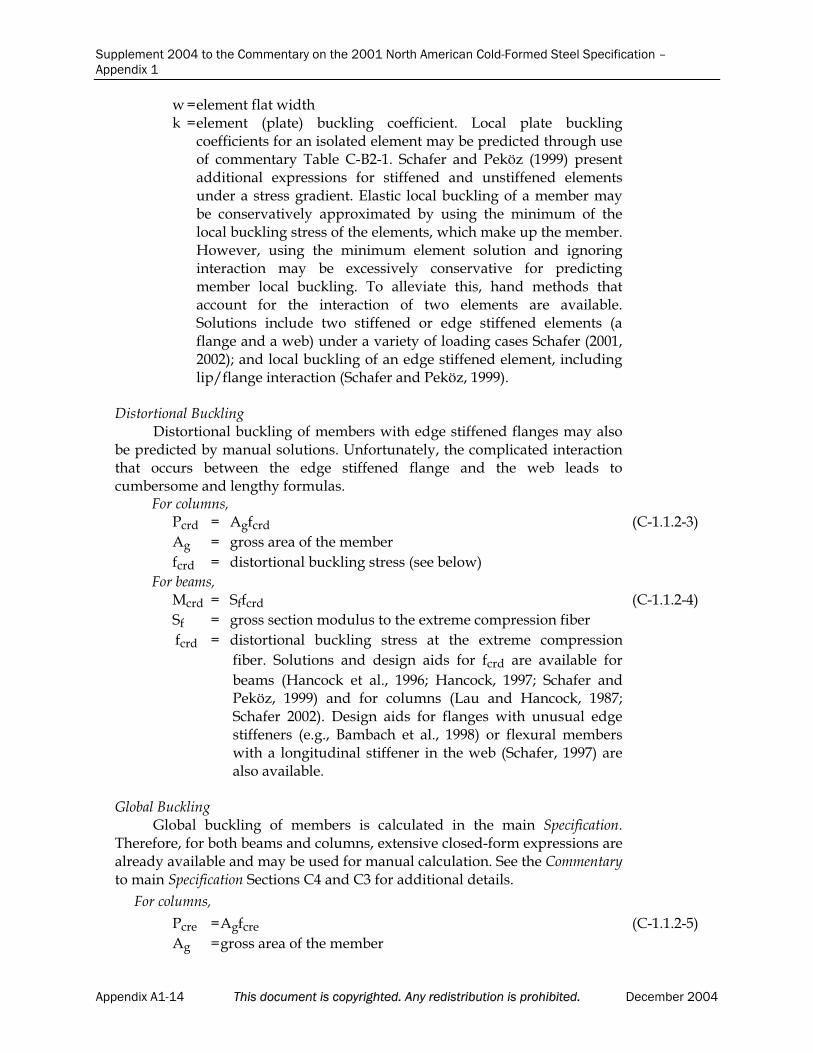
Supplement 2004 to the Commentary on the 2001 North American Cold-Formed Steel Specification –Appendix 1
w = element flat widthk =element (plate) buckling coefficient. Local plate buckling
coefficients for an isolated element may be predicted through use of commentary Table C-B2-1. Schafer and Peköz (1999) presentadditional expressions for stiffened and unstiffened elementsunder a stress gradient. Elastic local buckling of a member maybe conservatively approximated by using the minimum of the local buckling stress of the elements, which make up the member.However, using the minimum element solution and ignoring interaction may be excessively conservative for predictingmember local buckling. To alleviate this, hand methods that account for the interaction of two elements are available.Solutions include two stiffened or edge stiffened elements (aflange and a web) under a variety of loading cases Schafer (2001,2002); and local buckling of an edge stiffened element, including lip/flange interaction (Schafer and Peköz, 1999).
Distortional Buckling Distortional buckling of members with edge stiffened flanges may also
be predicted by manual solutions. Unfortunately, the complicated interaction that occurs between the edge stiffened flange and the web leads tocumbersome and lengthy formulas.
For columns,Pcrd = Agfcrd (C-1.1.2-3)
Ag = gross area of the member
fcrd = distortional buckling stress (see below)
For beams,Mcrd = Sffcrd (C-1.1.2-4)
Sf = gross section modulus to the extreme compression fiber
fcrd = distortional buckling stress at the extreme compression
fiber. Solutions and design aids for fcrd are available for
beams (Hancock et al., 1996; Hancock, 1997; Schafer andPeköz, 1999) and for columns (Lau and Hancock, 1987;Schafer 2002). Design aids for flanges with unusual edge stiffeners (e.g., Bambach et al., 1998) or flexural members with a longitudinal stiffener in the web (Schafer, 1997) arealso available.
Global BucklingGlobal buckling of members is calculated in the main Specification.
Therefore, for both beams and columns, extensive closed-form expressions arealready available and may be used for manual calculation. See the Commentaryto main Specification Sections C4 and C3 for additional details.
For columns,
Pcre =Agfcre (C-1.1.2-5)
Ag =gross area of the member
Appendix A1-14 This document is copyrighted. Any redistribution is prohibited. December 2004

Supplement 2004 to the Commentary on the 2001 North American Cold-Formed Steel Specification –Appendix 1
fcre = minimum of the elastic critical flexural, torsional, or flexural-
torsional buckling stress. fcre is equal to Fe of Section C4 of
the main Specification. The hand methods presented inSpecification sections C4.1 through C4.4 provide all necessary formula. Note, C4.4 specifically addresses the long-standing practice that Fe (or fcre) may be calculated by rational
analysis. Rational analysis hand solutions to long columnbuckling are available - see the Commentary for mainSpecification Section C4.4 as well as Yu (2000) or Hancock et al. (2001). The hand calculations may be quite lengthy, particular if member properties xo and Cw are unknown.
For beams,
Mcre = Sffcre (C-1.1.2-6)
Sf = gross section modulus to the extreme compression fiber
fcre = elastic critical lateral-torsional buckling stress. fcre is equal to
Fe of main Specification Section C3.1.2.1 for open cross-section
members and C3.1.2.2 for closed cross-section members. Hand solutions are well established for doubly- and singly-symmetric sections, but not so for point symmetric sections (zees). Fe of point-symmetric sections is taken as half of the
value for doubly-symmetric sections. Rational numericalanalysis may be desirable in cases where a close to exact solution is required.
1.1.3 Serviceability Determination
The provisions of this Appendix use a simplified approach to deflection calculations that assume the moment of inertia of the section for deflection calculations is linearly proportional to the strength of the section, determined atthe allowable stress of interest. This approximation avoids lengthy effectivesection calculations for deflection determination.
1.2 MEMBERS
1.2.1 Column Design
Commentary Section C4 provides a complete discussion on the behavior of cold-formed columns as it relates to the main Specification. This commentaryaddresses the specific issues raised by the use of the Direct Strength Method of Appendix 1 for the design of cold-formed columns. The thin-walled nature of cold-formed columns complicates behavior and design. Elastic buckling analysis reveals at least three buckling modes: local, distortional, and Euler (flexural,torsional, or flexural-torsional) that must be considered in design. Therefore, in addition to usual considerations for steel columns: material non-linearity (e.g., yielding), imperfections, and residual stresses, the individual role and potentialfor interaction of buckling modes must also be considered. The Direct StrengthMethod of this Appendix emerged through the combination of more refined
December 2004 This document is copyrighted. Any redistribution is prohibited. Appendix A1-15

Supplement 2004 to the Commentary on the 2001 North American Cold-Formed Steel Specification –Appendix 1
methods for local and distortional buckling prediction, improved understandingof the post-buckling strength and imperfection sensitivity in distortional failures,and the relatively large amount of available experimental data.
Fully effective or compact columns are generally well predicted by conventional column curves (AISC, 2001; Galambos, 1998, etc.). Therefore, the long column strength, Pne, follows the same practice as the main Specification and
uses the current AISC (2001) curves for strength prediction. The main Specification provides the long column strength in terms of a stress, Fn (Equations
C4-2 and C4-3). In the Direct Strength Method this is converted from a stress to astrength by multiplying the gross area, Ag, resulting in the formulas for Pne
given in Appendix 1. In the main Specification, column strength is calculated by multiplying the
long column stress, Fn, by the effective area, Ae, calculated at Fn. This accounts
for local buckling reductions in the actual column strength (i.e., local-global interaction). In the Direct Strength Method, this calculation is broken into two parts: the long column strength without any reduction for local buckling (Pne)
and the long column strength considering local-global interaction (Pn ).
The strength curves for local and distortional buckling of a fully bracedcolumn are presented in Figure C-1.2.1-1. The curves are presented as a functionof slenderness, which in this case refers to slenderness in the local or distortional mode, as opposed to traditional long column slenderness. Inelastic and post-buckling regimes are observed for both local and distortional buckling modes. The magnitude of the post-buckling reserve for the distortional buckling mode isless than the local buckling mode, as may be observed by the location of thestrength curves in relation to the critical elastic buckling curve.
The development and calibration of the Direct Strength provisions for columns are reported in Schafer (2000, 2002). The reliability of the columnprovisions was determined using the test data of Appendix Section 1.1.1.1 andthe provisions of Chapter F of the main Specification. Based on a target reliability,
, of 2.5, a resistance factor, , of 0.84 was calculated for all the investigatedcolumns. Based on this information the safety and resistance factors of Section 1.2.1 were determined for the pre-qualified members. For the United States and
Mexico = 0.85 was selected; while for Canada = 0.80 since a slightly higher
reliability, , of 3.0 is employed. The safety factor, , was back calculated from at an assumed dead to live load ratio of 1 to 5. Since the range of pre-qualified members is relatively large, extensions of the Direct Strength Method to geometries outside the pre-qualified set is allowed. Given the uncertain nature of this extension, increased safety factors and reduced resistance factors are applied in that case, per the rational analysis provisions of A1.1(b) of the mainSpecification.
The provisions of Appendix 1, applied to the columns of Section 1.1.1.1, are summarized in Figure C-1.2.1-2 below. The controlling strength is either byAppendix 1 Section 1.2.1.2, which considers local buckling interaction with long column buckling, or by Section 1.2.1.3, which considers the distortional mode alone. The controlling strength (minimum predicted of the two modes) is highlighted for the examined members by the choice of marker. Overall
Appendix A1-16 This document is copyrighted. Any redistribution is prohibited. December 2004
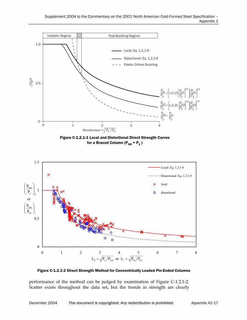
Supplement 2004 to the Commentary on the 2001 North American Cold-Formed Steel Specification – Appendix 1
December 2004 This document is copyrighted. Any redistribution is prohibited. Appendix A1-17
performance of the method can be judged by examination of Figure C-1.2.1-2. Scatter exists throughout the data set, but the trends in strength are clearly
��������6��� )��+7��8�����6���
�����9�!:%��%�%�+;
0����������9�!:%��%�%�+<
!���������������7��8����
=>��,,
,%.
�%,
�����
������
����
�����
� ����������
� ������
�
�����������������������
�
�
�
�����
� ���������
�����
�
Figure C-1.2.1-1 Local and Distortional Direct Strength Curves for a Braced Column (Pne = Py )
0
0.5
1
1.5
0 1 2 3 4 5 6 7 8
Local: Eq. 1.2.1-6
Distortional: Eq. 1.2.1-9
local
distortional
crnecrdyd PPorPP
ne
test
dy
test
P
P
or
P
P
Figure C-1.2.1-2 Direct Strength Method for Concentrically Loaded Pin-Ended Columns
Supplement 2004 to the Commentary on the 2001 North American Cold-Formed Steel Specification –Appendix 1
shown, and further, the scatter (variance) is similar to that of the mainSpecification. Since the main Specification has no rules for distortional buckling, the Direct Strength Method actually provides better agreement than the mainSpecification when compared with this test database for many members.
1.2.1.1 Flexural, Torsional, or Torsional-Flexural Buckling
As discussed in detail above, the strength expressions for long wavelength buckling of columns follow directly from Section C4 of the mainSpecification. These provisions are identical to those used for compact sectionhot-rolled columns in the AISC Specification (2001) and are fully discussed inthe Commentary to Section C4. The axial elastic strength, Pne, calculated in this
section represents the upper bound capacity for a given column. Actualcolumn strength is determined by considering reductions that may occur dueto local buckling, and performing a separate check on the distortional mode.See Section 1.1.2 for information on rational analysis methods for calculation of Pcre.
1.2.1.2 Local Buckling
The expression selected for local buckling of columns is shown in FigureC-1.2.1-1 and Figure C-1.2.1-2 and is discussed in Section 1.2.1. The potentialfor local-global interaction is presumed, thus the column strength in localbuckling is limited to a maximum of the long column strength, Pne. See
Section 1.1.2 for information on rational analysis methods for calculation of Pcr .
1.2.1.3 Distortional Buckling
The expression selected for distortional buckling of columns is shown in Figure C-1.2.1-1 and Figure C-1.2.1-2 and is discussed in Section 1.2.1. Basedon experimental test data and on the success of the Australian/New Zealandcode (see Hancock et al., 2001 for discussion and Hancock et al. 1994 for further details) the distortional buckling strength is limited to Py instead of
Pne. This presumes that distortional buckling failures are independent of long-
column behavior, i.e., little if any distortional-global interaction exists. See Section 1.1.2 for information on rational analysis methods for calculation of Pcrd.
1.2.2 Beam Design
Commentary Section C3 provides a complete discussion on the behavior of cold-formed beams as it relates to the main Specification. This commentaryaddresses the specific issues raised by the use of the Direct Strength Method of Appendix 1 for the design of cold-formed beams.
The thin-walled nature of cold-formed beams complicates behavior anddesign. Elastic buckling analysis reveals at least three buckling modes: local, distortional, and lateral-torsional buckling (for members in strong-axis bending)
Appendix A1-18 This document is copyrighted. Any redistribution is prohibited. December 2004
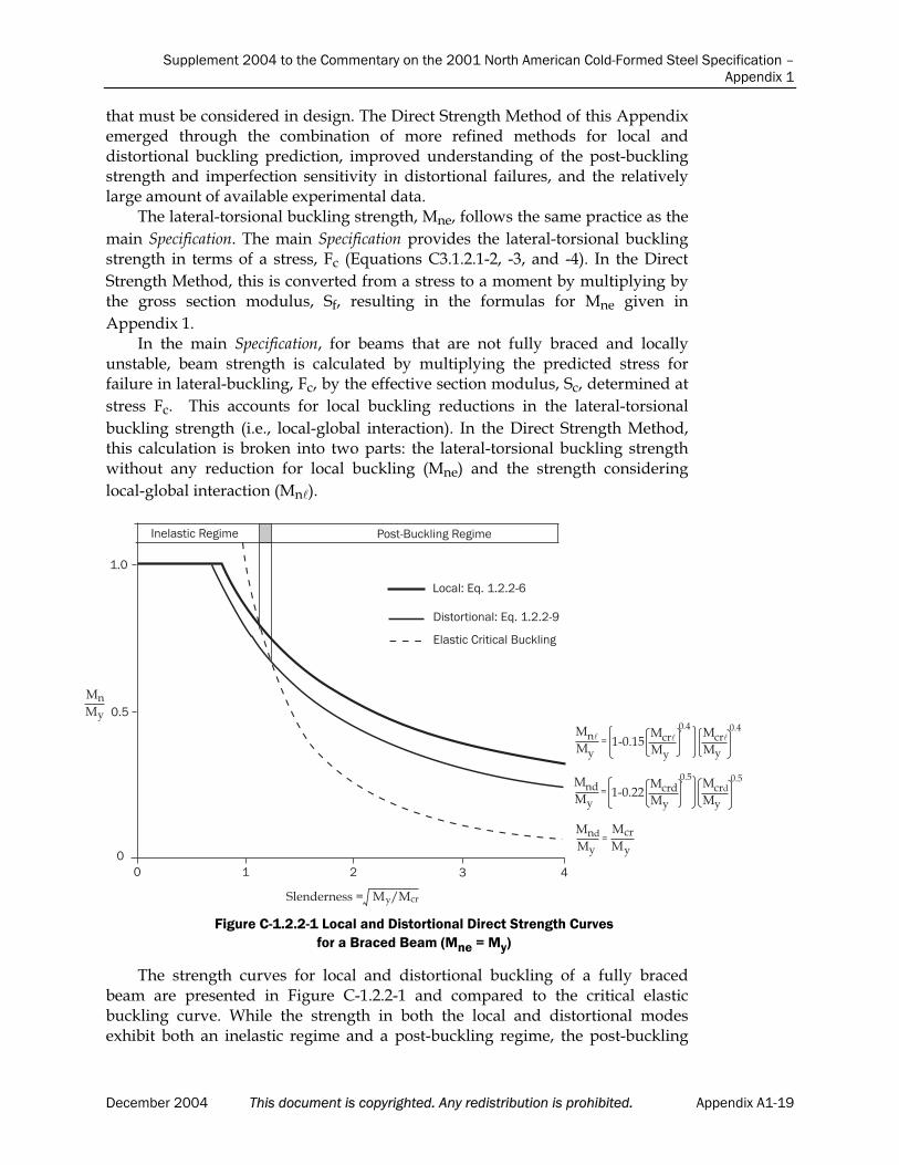
Supplement 2004 to the Commentary on the 2001 North American Cold-Formed Steel Specification – Appendix 1
December 2004 This document is copyrighted. Any redistribution is prohibited. Appendix A1-19
that must be considered in design. The Direct Strength Method of this Appendix emerged through the combination of more refined methods for local and distortional buckling prediction, improved understanding of the post-buckling strength and imperfection sensitivity in distortional failures, and the relatively large amount of available experimental data.
The lateral-torsional buckling strength, Mne, follows the same practice as the
main Specification. The main Specification provides the lateral-torsional buckling strength in terms of a stress, Fc (Equations C3.1.2.1-2, -3, and -4). In the Direct
Strength Method, this is converted from a stress to a moment by multiplying by the gross section modulus, Sf, resulting in the formulas for Mne given in
Appendix 1. In the main Specification, for beams that are not fully braced and locally
unstable, beam strength is calculated by multiplying the predicted stress for failure in lateral-buckling, Fc, by the effective section modulus, Sc, determined at
stress Fc. This accounts for local buckling reductions in the lateral-torsional
buckling strength (i.e., local-global interaction). In the Direct Strength Method, this calculation is broken into two parts: the lateral-torsional buckling strength without any reduction for local buckling (Mne) and the strength considering
local-global interaction (Mn ).
The strength curves for local and distortional buckling of a fully braced beam are presented in Figure C-1.2.2-1 and compared to the critical elastic buckling curve. While the strength in both the local and distortional modes exhibit both an inelastic regime and a post-buckling regime, the post-buckling
��������6��� )��+7��8�����6���
�����9�!:%��%�%�+;
0����������9�!:%��%�%�+<
!���������������7��8����
=>��,,
,%.
�%,
����
�����
� ����������
� ������
�
�����������������������
�����
������
�����
� ����������
� ������
�
Figure C-1.2.2-1 Local and Distortional Direct Strength Curves for a Braced Beam (Mne = My)
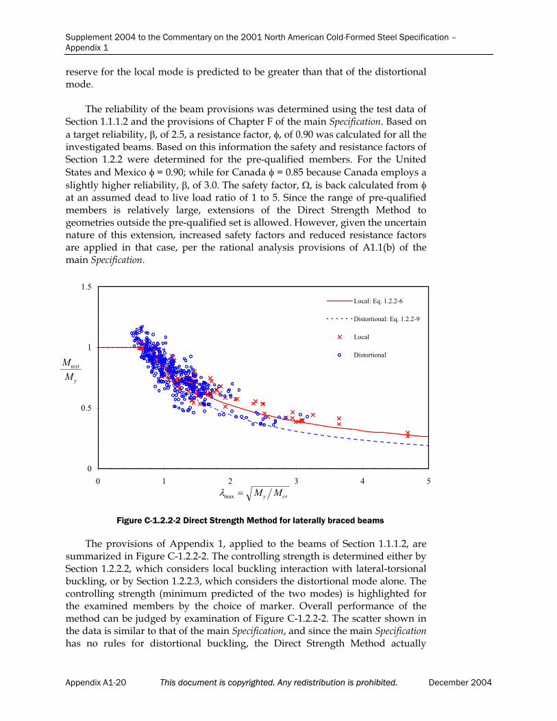
Supplement 2004 to the Commentary on the 2001 North American Cold-Formed Steel Specification –Appendix 1
reserve for the local mode is predicted to be greater than that of the distortional mode.
The reliability of the beam provisions was determined using the test data of Section 1.1.1.2 and the provisions of Chapter F of the main Specification. Based on
a target reliability, , of 2.5, a resistance factor, , of 0.90 was calculated for all the investigated beams. Based on this information the safety and resistance factors of Section 1.2.2 were determined for the pre-qualified members. For the United
States and Mexico = 0.90; while for Canada = 0.85 because Canada employs a
slightly higher reliability, , of 3.0. The safety factor, , is back calculated from at an assumed dead to live load ratio of 1 to 5. Since the range of pre-qualified members is relatively large, extensions of the Direct Strength Method to geometries outside the pre-qualified set is allowed. However, given the uncertainnature of this extension, increased safety factors and reduced resistance factors are applied in that case, per the rational analysis provisions of A1.1(b) of the main Specification.
The provisions of Appendix 1, applied to the beams of Section 1.1.1.2, are summarized in Figure C-1.2.2-2. The controlling strength is determined either by Section 1.2.2.2, which considers local buckling interaction with lateral-torsional buckling, or by Section 1.2.2.3, which considers the distortional mode alone. The controlling strength (minimum predicted of the two modes) is highlighted for the examined members by the choice of marker. Overall performance of themethod can be judged by examination of Figure C-1.2.2-2. The scatter shown inthe data is similar to that of the main Specification, and since the main Specificationhas no rules for distortional buckling, the Direct Strength Method actually
0
0.5
1
1.5
0 1 2 3 4 5
Local: Eq. 1.2.2-6
Distortional: Eq. 1.2.2-9
Local
Distortional
max M My cr
M
M
test
y
Figure C-1.2.2-2 Direct Strength Method for laterally braced beams
Appendix A1-20 This document is copyrighted. Any redistribution is prohibited. December 2004
Supplement 2004 to the Commentary on the 2001 North American Cold-Formed Steel Specification –Appendix 1
provides better agreement than the main Specification when compared with this test database for many members.
1.2.2.1 Lateral-Torsional Buckling
As discussed in detail above, the strength expressions for lateral-torsional buckling of beams follow directly from Section C3 of the main Specification and are fully discussed in Section C3 of the Commentary. The bending elastic buckling strength, Mne, calculated in this section represents
the upperbound capacity for a given beam. Actual beam strength is determined by considering reductions that may occur due to local bucklingand performing a separate check on the distortional mode. See Section 1.1.2for information on rational analysis methods for calculation of Mcre.
1.2.2.2 Local Buckling
The expression selected for local buckling of beams is shown in FiguresC-1.2.2-1 and C-1.2.2-2 and is discussed in Section 1.2.2. The use of the Direct Strength Method for local buckling and the development of the empiricalstrength expression is given in Schafer and Peköz (1998). The potential for local-global interaction is presumed; thus, the beam strength in local bucklingis limited to a maximum of the lateral-torsional buckling strength, Mne. For
fully braced beams, the maximum Mne value is the yield moment, My. See
Section 1.1.2 for information on rational analysis methods for calculation of Mcr .
1.2.2.3 Distortional Buckling
The expression selected for distortional buckling of beams is shown inFigures C-1.2.2-1 and C-1.2.2-2 and is discussed in Section 1.2.2. Based on experimental test data and on the success of the Australian/New Zealandcode (see Hancock, 2001 for discussion) the distortional buckling strength is limited to My instead of Mne. This presumes that distortional buckling failures
are independent of lateral-torsional buckling behavior, i.e., little if any distortional-global interaction exists. See Section 1.1.2 for information on rational analysis methods for calculation of Mcrd.
REFERENCES
Acharya, V.V. and R.M. Schuster (1998), “Bending Tests of Hat Section with Multiple Longitudinal Stiffeners,” Proceedings of the FourteenthInternational Specialty Conference on Cold-Formed Steel Structures, University of Missouri-Rolla, Rolla, MO, October, 1998.
American Institute of Steel Construction (2001), Manual of Steel Construction: Load and Resistance Factor Design, 3rd Edition, AmericanInstitute of Steel Construction, Chicago, IL.
American Iron and Steel Institute (2002), Cold-Formed Steel Design Manual,American Iron and Steel Institute, Washington, D.C.
December 2004 This document is copyrighted. Any redistribution is prohibited. Appendix A1-21

Supplement 2004 to the Commentary on the 2001 North American Cold-Formed Steel Specification –Appendix 1
Bambach, M.R., J.T. Merrick and G.J. Hancock (1998), “Distortional Buckling Formulae for Thin Walled Channel and Z-Sections with ReturnLips,” Proceedings of the 14th International Specialty Conference on Cold-Formed Steel Structures, University of Missouri-Rolla, Rolla, MO, October1998, 21-38.
Bernard, E.S. (1993), “Flexural Behavior of Cold-Formed Profiled SteelDecking,” Ph.D. Thesis, University of Sydney, Australia.
Cheung, Y.K. and L.G. Tham (1998), Finite Strip Method, CRC Press.
Cohen, J. M. (1987), “Local Buckling Behavior of Plate Elements,”Department of Structural Engineering Report, Cornell University, Ithaca,NY, 1987.
Cook, R.D., D.S. Malkus and M.E. Plesha (1989), Concepts and Applications of Finite Element Analysis, John Wiley & Sons, 3rd Ed.
Davies, J.M. and C. Jiang (1996), “Design of Thin-Walled Beams forDistortional Buckling,” Proceedings of the Thirteenth International Specialty Conference on Cold-Formed Steel Structures, University of Missouri-Rolla, Rolla, MO, October 1996, 141-154.
Davies, J.M., C. Jiang and V. Ungureanu (1998), “Buckling ModeInteraction in Cold-Formed Steel Columns and Beams,” Proceedings of theFourteenth International Specialty Conference on Cold-Formed Steel Structures,University of Missouri-Rolla, Rolla, MO, October 1998, 53-68.
Davies, J.M., P. Leach, D. Heinz (1994), “Second-Order Generalised Beam Theory.” Journal of Constructional Steel Research, Elsevier, 31 (2-3) 221-242.
Desmond, T.P. (1977), “The Behavior and Design of Thin-Walled Compression Elements with Longitudinal Stiffeners,” Ph.D. Thesis,Cornell University, Ithaca, NY, 1777.
Ellifritt, D., B. Glover and J. Hren (1997), “Distortional Buckling ofChannels and Zees Not Attached to Sheathing,” Report for the AmericanIron and Steel Institute, Washington D.C., 1997.
Elzein, A. (1991), Plate Stability by Boundary Element Method, Springer-Verlag, NY, 1991.
Galambos, T.V. (1998), Guide to Stability Design Criteria for MetalStructures, John Wiley & Sons, 5th Ed.
Hancock, G.J. (1997), “Design for Distortional Buckling of Flexural Members,” Thin-Walled Structures, 27(1), 3-12, Elsevier Science Ltd.
Hancock, G.J., Y.B. Kwon and E.S. Bernard (1994), “Strength DesignCurves for Thin-Walled Sections Undergoing Distortional Buckling,”Journal of Constructional Steel Research, Elsevier, 31(2-3), 169-186.
Hancock, G.J., T.M. Murray and D.S. Ellifritt (2001), Cold-Formed SteelStructures to the AISI Specification, Marcell-Dekker, New York, New York.
Appendix A1-22 This document is copyrighted. Any redistribution is prohibited. December 2004
Supplement 2004 to the Commentary on the 2001 North American Cold-Formed Steel Specification –Appendix 1
Hancock, G.J., C.A. Rogers and R.M. Schuster (1996) “Comparison of theDistortional Buckling Method for Flexural Members with Tests.”Proceedings of the Thirteenth International Specialty Conference on Cold-Formed Steel Structures, University of Missouri-Rolla, Rolla, MO, October1998, 125-140.
Harik, I.E., X. Liu and R. Ekambaram (1991), “Elastic Stability of Pates with Varying Rigidities,” Computers and Structures, 38 (2) 161-168.
Höglund, T. (1980), “Design of Trapezoidal Sheeting Provided with Stiffeners in the Flanges and Webs,” Swedish Council for Building Research,Stockholm, Sweden, D28:1980.
König, J. (1978), “Transversally Loaded Thin-Walled C-Shaped PanelsWith Intermediate Stiffeners,” Swedish Council for Building Research,Stockholm, Sweden, D7:1978.
Kwon, Y.B. and G.J. Hancock (1992), “Strength Tests of Cold-FormedChannel Sections undergoing Local and Distortional Buckling,” Journal ofStructural Engineering, ASCE, Vol. 117, No. 2, 1786 – 1803.
LaBoube, R.A. and W. W. Yu (1978), “Structural Behavior of Beam WebsSubjected to Bending Stress,” Civil Engineering Study Structural Series, 78-1, Department of Civil Engineering, University of Missouri-Rolla, Rolla, Missouri.
Lau, S.C.W., and G.J Hancock (1987),. ”Distortional Buckling Formulasfor Channel Columns,” Journal of Structural Engineering, ASCE, Vol. 113, No. 5, 1063 – 1078.
Loughlan, J. (1979), “Mode Interaction in Lipped Channel Columns under Concentric or Eccentric Loading,” Ph.D. Thesis, University of Strathclyde, Glasgow.
Miller, T.H. and T. Peköz (1994), “Load-Eccentricity Effects on Cold-Formed Steel Lipped- Channel Columns,” Journal of StructuralEngineering, ASCE, Vol. 120, No. 3, 805-823.
Moreyra, M.E. (1993), “The Behavior of Cold-Formed Lipped Channels under Bending,” M.S. Thesis, Cornell University, Ithaca, New York.
Mulligan, G.P. (1983), “The Influence of Local Buckling on the Structural Behavior of Singly-Symmetric Cold-Formed Steel Columns,” Ph.D.Thesis, Cornell University, Ithaca, New York.
Papazian, R.P., R.M. Schuster and M. Sommerstein (1994), “Multiple Stiffened Deck Profiles,” Proceedings of the Twelfth International SpecialtyConference on Cold-Formed Steel Structures, University of Missouri-Rolla, Rolla, MO, October, 1994, 217-228.
Phung, N., W.W. Yu (1978), “Structural Behavior of LongitudinallyReinforced Beam Webs,” Civil Engineering Study Structural Series,Department of Civil Engineering, 78-6, University of Missouri-Rolla.
Polyzois, D., P. Charnvarnichborikarn (1993), “Web-Flange Interaction in Cold-Formed Steel Z-Section Columns,” Journal of Structural Engineering,ASCE, Vol. 119, No. 9, 2607-2628.
December 2004 This document is copyrighted. Any redistribution is prohibited. Appendix A1-23
Supplement 2004 to the Commentary on the 2001 North American Cold-Formed Steel Specification –Appendix 1
Quispe, L., G.J. Hancock (2002), “Direct Strength Method for the Designof Purlins,” Proceedings of the 16th International Specialty Conference on Cold-Formed Steel Structures, University of Missouri-Rolla, Rolla, MO, October2002, 561-572.
Rogers, C.A. (1995), “Interaction Buckling of Flange, Edge Stiffener andWeb of C-Sections in Bending,” M.S. Thesis, University of Waterloo, Ontario, Canada.
Schafer, B.W. (1997), “Cold-Formed Steel Behavior and Design: Analyticaland Numerical Modeling of Elements and Members with Longitudinal Stiffeners,” Ph.D. Thesis, Cornell University, Ithaca, New York.
Schafer, B.W. (2000), “Distortional Buckling of Cold-Formed SteelColumns: Final Report,” Sponsored by the American Iron and SteelInstitute, Washington, D.C.
Schafer, B.W. (2001), “Progress Report 2: Test Verification of the Effect of Stress Gradient on Webs of Cee and Zee Sections,” submitted to the AISIand MBMA, July 2001.
Schafer, B.W. (2002), “Local, Distortional, and Euler Buckling in Thin-walled Columns,” Journal of Structural Engineering, ASCE, Vol. 128, No. 3, 289-299.
Schafer, B.W. (2002b), “Progress on the Direct Strength Method,”Proceedings of the 16th International Specialty Conference on Cold-Formed SteelStructures, Orlando, FL. 647-662.
Schafer, B.W., T. Peköz, (1998), “Direct Strength Prediction of Cold-Formed Steel Members using Numerical Elastic Buckling Solutions,”Fourteenth International Specialty Conference on Cold-Formed Steel Structures,University of Missouri-Rolla, Rolla, MO, October 1998.
Schafer, B.W. and T. Peköz, (1999), “Laterally Braced Cold-Formed Steel Flexural Members with Edge Stiffened Flanges.” Journal of StructuralEngineering, ASCE, Vol. 125, No. 2.
Schardt, R. (1989), Verallgemeinerte Technische Biegetheorie [GeneralizedBeam Theory], Springer-Verlag, Berlin.
Schardt, R. and W. Schrade (1982), “Kaltprofil-Pfetten,” Institut FürStatik, Technische Hochschule Darmstadt, Bericht Nr. 1, Darmstadt.
Schuster, R.M. (1992), “Testing of Perforated C-Stud Sections in Bending,”Report for the Canadian Sheet Steel Building Institute, University of Waterloo, Waterloo Ontario.
Shan, M., R.A. LaBoube and W. W. Yu (1994), “Behavior of Web Elementswith Openings Subjected to Bending, Shear and the Combination of Bending and Shear,” Civil Engineering Study Structural Series, 94-2, Department of Civil Engineering, University of Missouri-Rolla, Rolla,Missouri.
Silvestre, N. and D. Camotim (2002a), “First-Order Generalised BeamTheory for Arbitrary Orthotropic Materials,” Thin-Walled Structures,Elsevier. Vol. 40, 755-789
Appendix A1-24 This document is copyrighted. Any redistribution is prohibited. December 2004

Supplement 2004 to the Commentary on the 2001 North American Cold-Formed Steel Specification –Appendix 1
Silvestre, N. and D. Camotim (2002b), “Second-Order Generalised Beam Theory for Arbitrary Orthotropic Materials,” Thin-Walled Structures,Elsevier. Vol. 40, 791-820
Thomasson, P. (1978), “Thin-walled C-shaped Panels in AxialCompression,” Swedish Council for Building Research, D1:1978, Stockholm,Sweden.
Willis, C.T. and B. Wallace (1990), “Behavior of Cold-Formed SteelPurlins under Gravity Loading,” Journal of Structural Engineering, ASCE.Vol. 116, No. 8.
Yu, W.W. (2000), Cold-Formed Steel Design, John Wiley & Sons, Inc.
Zienkiewicz, O.C. and R.L. Taylor (1989), The Finite Element Method: Volume 1 Basic Formulations and Linear Problems, McGraw Hill, 4th Ed.
Zienkiewicz, O.C. and R.L. Taylor (1991), The Finite Element Method: Volume 2 Solid and Fluid Mechanics Dynamics and Non-linearity, McGrawHill, 4th Ed.
December 2004 This document is copyrighted. Any redistribution is prohibited. Appendix A1-25