supplement: statically indeterminate frames supplement - cantilever...supplement cantilever method...
TRANSCRIPT
Supplement
Cantilever Method
Page 1 of 15
Supplement: Statically Indeterminate Frames
Approximate Analysis - Cantilever Method
In this supplement, we consider another approximate method of solving statically
indeterminate frames subjected to lateral loads known as the “Cantilever Method.”
• Like the “Portal Method,” this approximate analysis provides a means to solve a
statically indeterminate problem using a simple model of the structure that is
statically determinate.
• This method is more accurate than the “Portal Method” for tall and narrow
buildings.
Statically Indeterminate Frames
Assumptions for the analysis of statically indeterminate frames by the cantilever
method include the following.
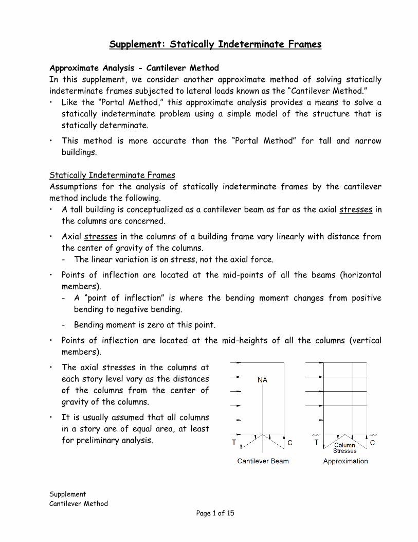
• A tall building is conceptualized as a cantilever beam as far as the axial stresses in
the columns are concerned.
• Axial stresses in the columns of a building frame vary linearly with distance from
the center of gravity of the columns.
- The linear variation is on stress, not the axial force.
• Points of inflection are located at the mid-points of all the beams (horizontal
members).
- A “point of inflection” is where the bending moment changes from positive
bending to negative bending.
- Bending moment is zero at this point.
• Points of inflection are located at the mid-heights of all the columns (vertical
members).
• The axial stresses in the columns at
each story level vary as the distances
of the columns from the center of
gravity of the columns.
• It is usually assumed that all columns
in a story are of equal area, at least
for preliminary analysis.
Supplement
Cantilever Method
Page 2 of 15
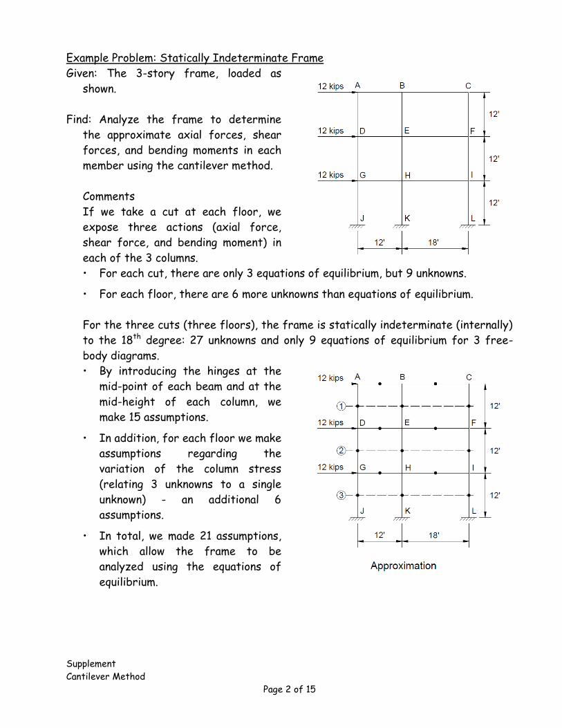
Example Problem: Statically Indeterminate Frame
Given: The 3-story frame, loaded as
shown.
Find: Analyze the frame to determine
the approximate axial forces, shear
forces, and bending moments in each
member using the cantilever method.
Comments
If we take a cut at each floor, we
expose three actions (axial force,
shear force, and bending moment) in
each of the 3 columns.
• For each cut, there are only 3 equations of equilibrium, but 9 unknowns.
• For each floor, there are 6 more unknowns than equations of equilibrium.
For the three cuts (three floors), the frame is statically indeterminate (internally)
to the 18th degree: 27 unknowns and only 9 equations of equilibrium for 3 free-
body diagrams.
• By introducing the hinges at the
mid-point of each beam and at the
mid-height of each column, we
make 15 assumptions.
• In addition, for each floor we make
assumptions regarding the
variation of the column stress
(relating 3 unknowns to a single
unknown) - an additional 6
assumptions.
• In total, we made 21 assumptions,
which allow the frame to be
analyzed using the equations of
equilibrium.
Supplement
Cantilever Method
Page 3 of 15
Solution
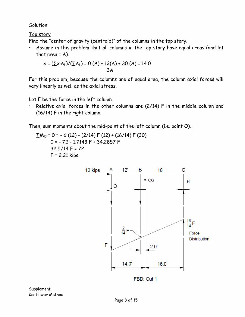
Top story
Find the “center of gravity (centroid)” of the columns in the top story.
• Assume in this problem that all columns in the top story have equal areas (and let
that area = A).
x = (∑xiAi )/(∑Ai ) = 0 (A) + 12(A) + 30 (A) = 14.0
3A
For this problem, because the columns are of equal area, the column axial forces will
vary linearly as well as the axial stress.
Let F be the force in the left column.
• Relative axial forces in the other columns are (2/14) F in the middle column and
(16/14) F in the right column.
Then, sum moments about the mid-point of the left column (i.e. point O).
∑MO = 0 = - 6 (12) - (2/14) F (12) + (16/14) F (30)
0 = - 72 - 1.7143 F + 34.2857 F
32.5714 F = 72
F = 2.21 kips
Supplement
Cantilever Method
Page 4 of 15
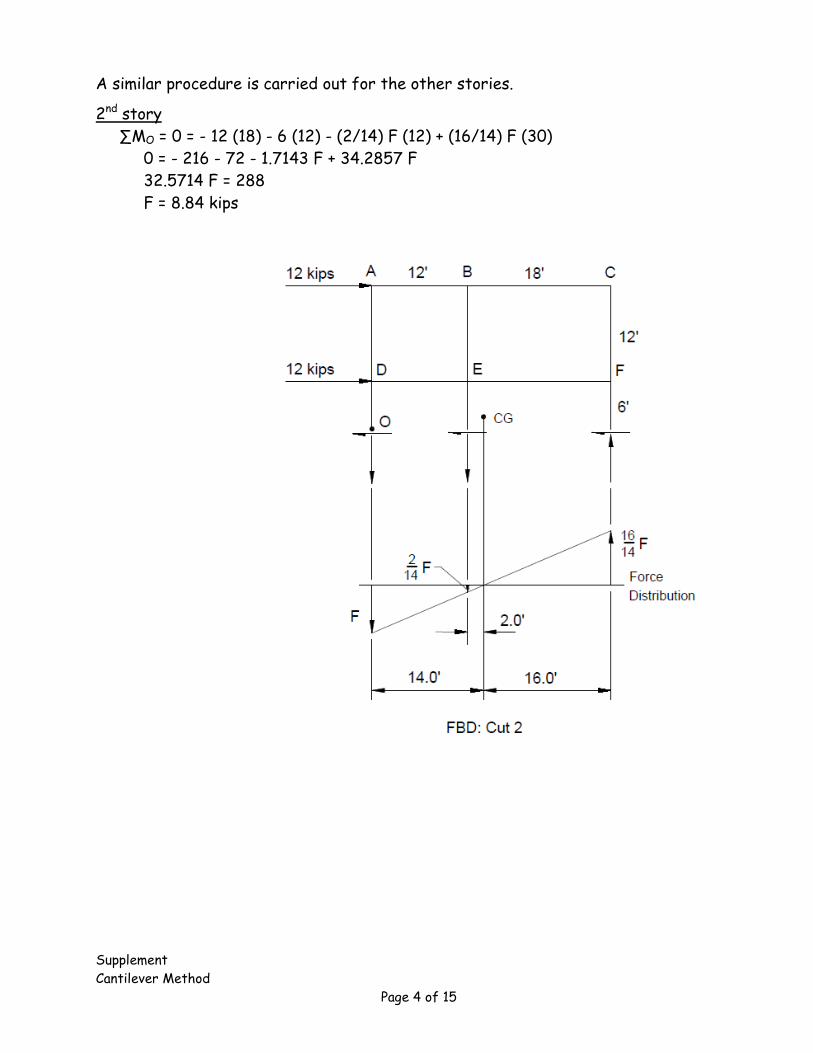
A similar procedure is carried out for the other stories.
2nd story
∑MO = 0 = - 12 (18) - 6 (12) - (2/14) F (12) + (16/14) F (30)
0 = - 216 - 72 - 1.7143 F + 34.2857 F
32.5714 F = 288
F = 8.84 kips
Supplement
Cantilever Method
Page 5 of 15
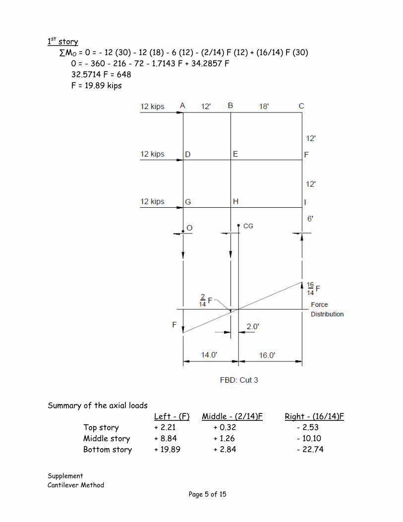
1st story
∑MO = 0 = - 12 (30) - 12 (18) - 6 (12) - (2/14) F (12) + (16/14) F (30)
0 = - 360 - 216 - 72 - 1.7143 F + 34.2857 F
32.5714 F = 648
F = 19.89 kips
Summary of the axial loads
Left - (F) Middle - (2/14)F Right - (16/14)F
Top story + 2.21 + 0.32 - 2.53
Middle story + 8.84 + 1.26 - 10.10
Bottom story + 19.89 + 2.84 - 22.74
Supplement
Cantilever Method
Page 6 of 15
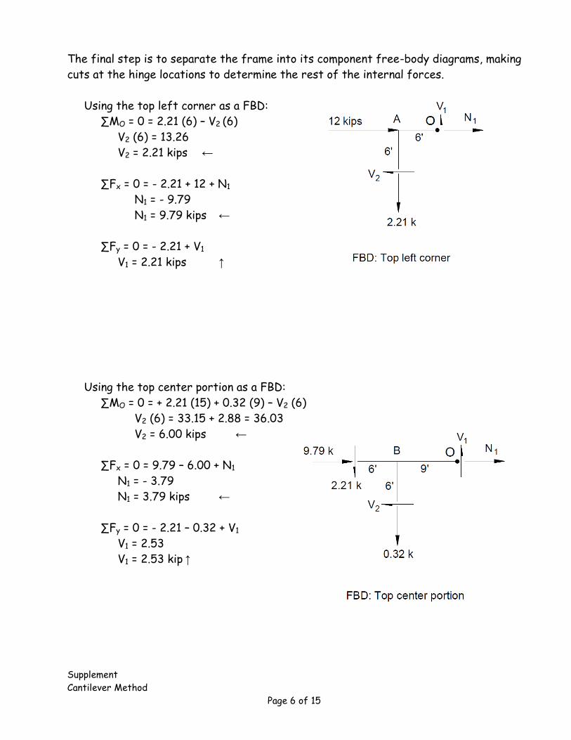
The final step is to separate the frame into its component free-body diagrams, making
cuts at the hinge locations to determine the rest of the internal forces.
Using the top left corner as a FBD:
∑MO = 0 = 2.21 (6) – V2 (6)
V2 (6) = 13.26
V2 = 2.21 kips ←
∑Fx = 0 = - 2.21 + 12 + N1
N1 = - 9.79
N1 = 9.79 kips ←
∑Fy = 0 = - 2.21 + V1
V1 = 2.21 kips ↑
Using the top center portion as a FBD:
∑MO = 0 = + 2.21 (15) + 0.32 (9) – V2 (6)
V2 (6) = 33.15 + 2.88 = 36.03
V2 = 6.00 kips ←
∑Fx = 0 = 9.79 – 6.00 + N1
N1 = - 3.79
N1 = 3.79 kips ←
∑Fy = 0 = - 2.21 – 0.32 + V1
V1 = 2.53
V1 = 2.53 kip ↑
Supplement
Cantilever Method
Page 7 of 15
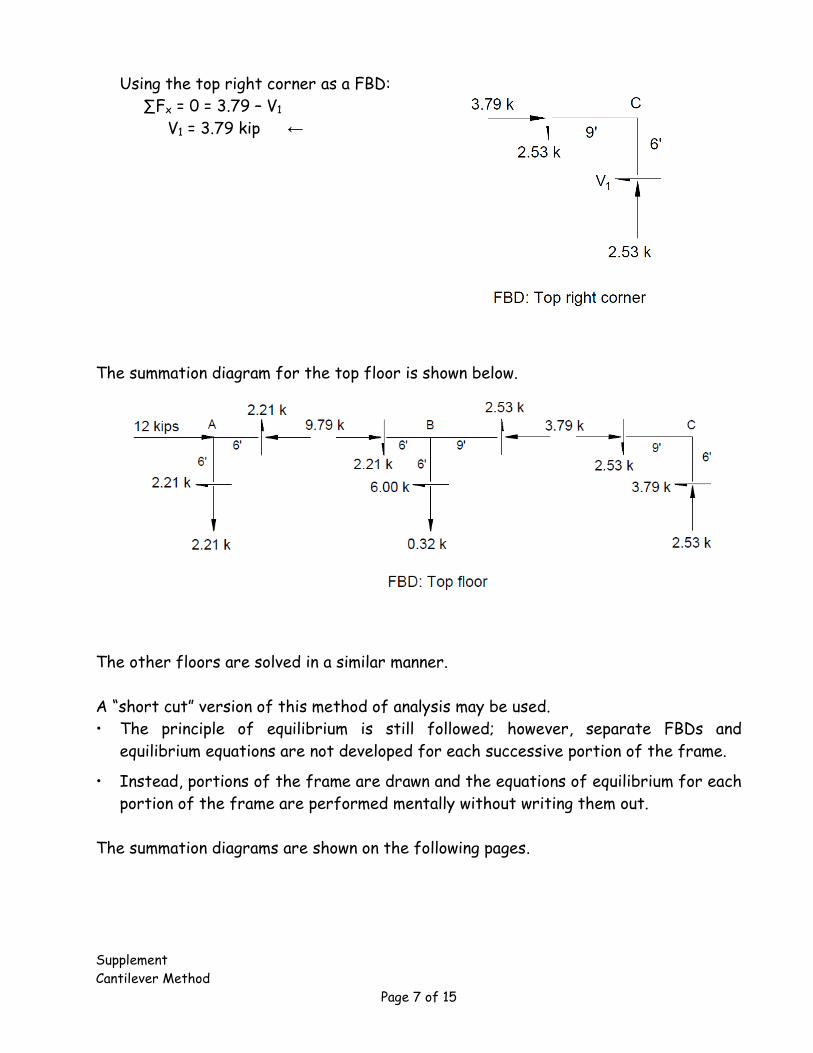
Using the top right corner as a FBD:
∑Fx = 0 = 3.79 – V1
V1 = 3.79 kip ←
The summation diagram for the top floor is shown below.
The other floors are solved in a similar manner.
A “short cut” version of this method of analysis may be used.
• The principle of equilibrium is still followed; however, separate FBDs and
equilibrium equations are not developed for each successive portion of the frame.
• Instead, portions of the frame are drawn and the equations of equilibrium for each
portion of the frame are performed mentally without writing them out.
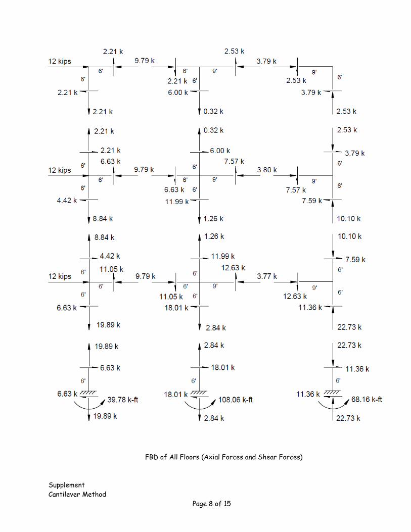
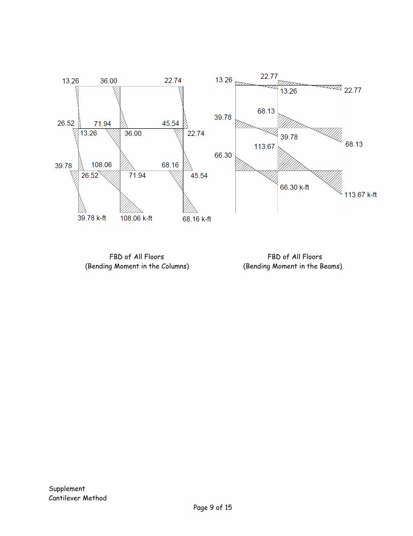
The summation diagrams are shown on the following pages.
Supplement
Cantilever Method
Page 8 of 15
FBD of All Floors (Axial Forces and Shear Forces)
Supplement
Cantilever Method
Page 9 of 15
FBD of All Floors FBD of All Floors
(Bending Moment in the Columns) (Bending Moment in the Beams)
Supplement
Cantilever Method
Page 10 of 15
Comparison with other methods
If the frame is designed according to the forces determined from the Portal Method
or Cantilever Method, the frame will be safe but not necessarily efficient.
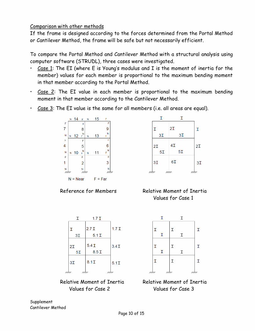
To compare the Portal Method and Cantilever Method with a structural analysis using
computer software (STRUDL), three cases were investigated.
• Case 1: The EI (where E is Young’s modulus and I is the moment of inertia for the
member) values for each member is proportional to the maximum bending moment
in that member according to the Portal Method.
• Case 2: The EI value in each member is proportional to the maximum bending
moment in that member according to the Cantilever Method.
• Case 3: The EI value is the same for all members (i.e. all areas are equal).
Reference for Members Relative Moment of Inertia
Values for Case 1
Relative Moment of Inertia Relative Moment of Inertia
Values for Case 2 Values for Case 3
Supplement
Cantilever Method
Page 11 of 15
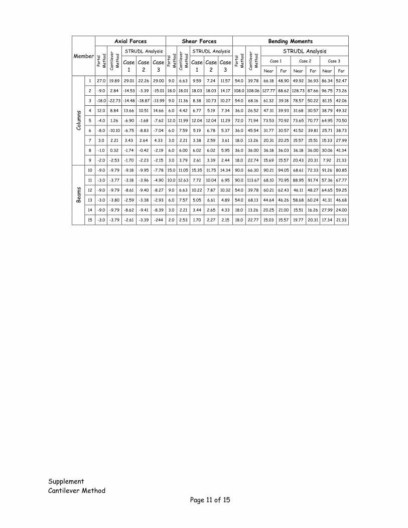
Member
Axial Forces Shear Forces Bending Moments
Port
al
Met
hod
Can
tile
ver
Met
hod
STRUDL Analysis
Port
al
Met
hod
Can
tile
ver
Met
hod
STRUDL Analysis
Port
al
Met
hod
Can
tile
ver
Met
hod
STRUDL Analysis
Case
1
Case
2
Case
3
Case
1
Case
2
Case
3
Case 1 Case 2 Case 3
Near Far Near Far Near Far
Col
umns
1 27.0 19.89 29.01 22.26 29.00 9.0 6.63 9.59 7.24 11.57 54.0 39.78 66.18 48.90 49.92 36.93 86.34 52.47
2 -9.0 2.84 -14.53 -3.39 -15.01 18.0 18.01 18.03 18.03 14.17 108.0 108.06 127.77 88.62 128.73 87.66 96.75 73.26
3 -18.0 -22.73 -14.48 -18.87 -13.99 9.0 11.36 8.38 10.73 10.27 54.0 68.16 61.32 39.18 78.57 50.22 81.15 42.06
4 12.0 8.84 13.66 10.51 14.66 6.0 4.42 6.77 5.19 7.34 36.0 26.52 47.31 39.93 31.68 30.57 38.79 49.32
5 -4.0 1.26 -6.90 -1.68 -7.62 12.0 11.99 12.04 12.04 11.29 72.0 71.94 73.53 70.92 73.65 70.77 64.95 70.50
6 -8.0 -10.10 -6.75 -8.83 -7.04 6.0 7.59 5.19 6.78 5.37 36.0 45.54 31.77 30.57 41.52 39.81 25.71 38.73
7 3.0 2.21 3.43 2.64 4.33 3.0 2.21 3.38 2.59 3.61 18.0 13.26 20.31 20.25 15.57 15.51 15.33 27.99
8 -1.0 0.32 -1.74 -0.42 -2.19 6.0 6.00 6.02 6.02 5.95 36.0 36.00 36.18 36.03 36.18 36.00 30.06 41.34
9 -2.0 -2.53 -1.70 -2.23 -2.15 3.0 3.79 2.61 3.39 2.44 18.0 22.74 15.69 15.57 20.43 20.31 7.92 21.33
Beam
s
10 -9.0 -9.79 -9.18 -9.95 -7.78 15.0 11.05 15.35 11.75 14.34 90.0 66.30 90.21 94.05 68.61 72.33 91.26 80.85
11 -3.0 -3.77 -3.18 -3.96 -4.90 10.0 12.63 7.72 10.04 6.95 90.0 113.67 68.10 70.95 88.95 91.74 57.36 67.77
12 -9.0 -9.79 -8.61 -9.40 -8.27 9.0 6.63 10.22 7.87 10.32 54.0 39.78 60.21 62.43 46.11 48.27 64.65 59.25
13 -3.0 -3.80 -2.59 -3.38 -2.93 6.0 7.57 5.05 6.61 4.89 54.0 68.13 44.64 46.26 58.68 60.24 41.31 46.68
14 -9.0 -9.79 -8.62 -9.41 -8.39 3.0 2.21 3.44 2.65 4.33 18.0 13.26 20.25 21.00 15.51 16.26 27.99 24.00
15 -3.0 -3.79 -2.61 -3.39 -244 2.0 2.53 1.70 2.27 2.15 18.0 22.77 15.03 15.57 19.77 20.31 17.34 21.33
Supplement
Cantilever Method
Page 12 of 15
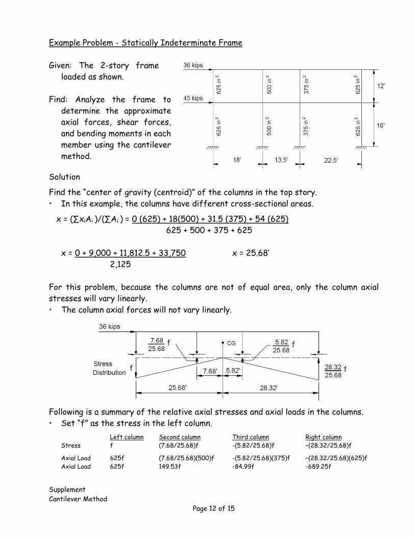
Example Problem - Statically Indeterminate Frame
Given: The 2-story frame
loaded as shown.
Find: Analyze the frame to
determine the approximate
axial forces, shear forces,
and bending moments in each
member using the cantilever
method.
Solution
Find the “center of gravity (centroid)” of the columns in the top story.
• In this example, the columns have different cross-sectional areas.
x = (∑xiAi )/(∑Ai ) = 0 (625) + 18(500) + 31.5 (375) + 54 (625)
625 + 500 + 375 + 625
x = 0 + 9,000 + 11,812.5 + 33,750 x = 25.68’
2,125
For this problem, because the columns are not of equal area, only the column axial
stresses will vary linearly.
• The column axial forces will not vary linearly.
Following is a summary of the relative axial stresses and axial loads in the columns.
• Set “f” as the stress in the left column.
Left column Second column Third column Right column
Stress f (7.68/25.68)f -(5.82/25.68)f –(28.32/25.68)f
Axial Load 625f (7.68/25.68)(500)f -(5.82/25.68)(375)f –(28.32/25.68)(625)f
Axial Load 625f 149.53f -84.99f -689.25f
Supplement
Cantilever Method
Page 13 of 15
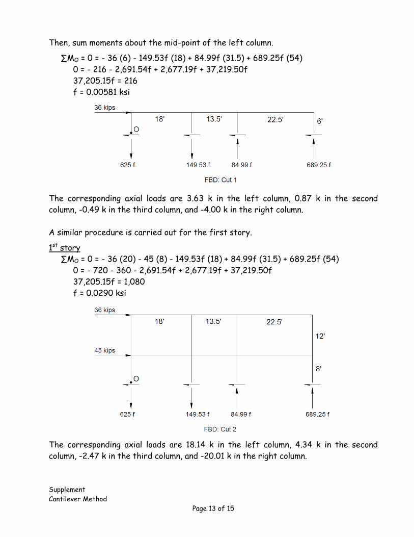
Then, sum moments about the mid-point of the left column.
∑MO = 0 = - 36 (6) - 149.53f (18) + 84.99f (31.5) + 689.25f (54)
0 = - 216 - 2,691.54f + 2,677.19f + 37,219.50f
37,205.15f = 216
f = 0.00581 ksi
The corresponding axial loads are 3.63 k in the left column, 0.87 k in the second
column, -0.49 k in the third column, and -4.00 k in the right column.
A similar procedure is carried out for the first story.
1st story
∑MO = 0 = - 36 (20) - 45 (8) - 149.53f (18) + 84.99f (31.5) + 689.25f (54)
0 = - 720 - 360 - 2,691.54f + 2,677.19f + 37,219.50f
37,205.15f = 1,080
f = 0.0290 ksi
The corresponding axial loads are 18.14 k in the left column, 4.34 k in the second
column, -2.47 k in the third column, and -20.01 k in the right column.
Supplement
Cantilever Method
Page 14 of 15
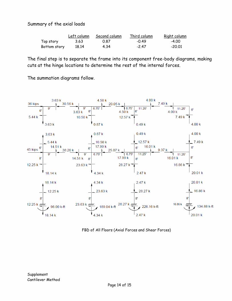
Summary of the axial loads
Left column Second column Third column Right column
Top story 3.63 0.87 -0.49 -4.00
Bottom story 18.14 4.34 -2.47 -20.01
The final step is to separate the frame into its component free-body diagrams, making
cuts at the hinge locations to determine the rest of the internal forces.
The summation diagrams follow.
FBD of All Floors (Axial Forces and Shear Forces)
Supplement
Cantilever Method
Page 15 of 15
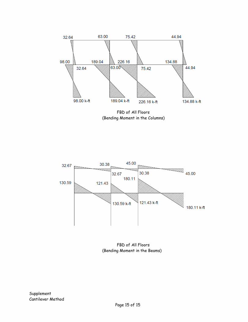
FBD of All Floors
(Bending Moment in the Columns)
FBD of All Floors
(Bending Moment in the Beams)