supplement to certificate series s034 …...• api mpms chapter 11; • astm table d1250-04, 54b...
TRANSCRIPT

Issue Date: Reference No:
16 May 2014 T1119/0011
Signatory: for
P R Dixon Chief Executive
National Measurement Office | Stanton Avenue | Teddington | TW11 0JZ | United Kingdom Tel +44 (0)20 8943 7272 | Fax +44 (0)20 8943 7270 | Web www.bis.gov.uk/nmo
NMO is an Executive Agency of the Department for Business Innovation & Skills
(1828, 1918, 1940, 1958, 1967, 2017, 2162, 2176, 2286, 2461, 2486, 2536, 2609, 2616, 2619, 2650, 2739, 2780, 2805, 2806)
III(5)a
SUPPLEMENT TO CERTIFICATE Series S034 Revision 4
issued by:
The National Measurement Office
issued to:
Temptronix Inc 704-70 Arthur Street Winnipeg, Manitoba, Canada, R3B 1G7
Authorisation is hereby given by the Secretary of State for Business, Innovation & Skills for the above Certificates of approval relating to a pattern of a liquid flowmeter to be modified as described below.
Certification No. Supplement No Certification No. Supplement No.
1828/40*(1) 60 2486/54* 72
1918/74* 91 2536 78
1940 92 2609(1) 3
1958/53* 76 2616 18
1967/66* 83 2619/43* 61
2017 94 2650/35* 75
2162/92* 110 2739 5
2176/78* 98 2780 25
2286/58* 77 2805 4
2461/26* 41 2806 4
(*) Refers to the dispenser only, the self service or other devices described in these certificates do not form part of this approval. (1) These Certificates have expired, but are quoted as they may be relevant for previous versions of this certificate
As described in the above Certificates but modified to have an automatic temperature compensation device (ATC), as detailed in the descriptive annex, and having the following characteristics:-
DISPENSER Dispensers described in the above certification numbers:
AUTOMATIC TEMPERATURE COMPENSATION DEVICE (ATC):
GENIUS ATC for petrol and diesel: software version V1.09.
This revision replaces previous versions of the certificate.
2
CONTENTS
1 INTRODUCTION
2 CONSTRUCTION
3 OPERATION
4 CONDITIONS
5 Table 1 Dispenser Model Identification
6 CERTIFICATE HISTORY
ILLUSTRATIONS
Figure 1 GENIUS ATC and Enclosure
Figure 2 Schematic of ATC Main Board, and Connections
Figure 3 Positions of Dip Switches S2 – S5, S6 – S9, S10 and S11
Figure 4 Main ATC Board Settings
Figure 5 IS Barrier Board and Connections
Figure 6 Example Mounting of Temperature Probe
Figure 7 Example Mounting of Temperature Probe
Figure 8 Example Mounting of Temperature Probe
Figure 9 Example Mounting of Temperature Probe
Figure 10 Example Mounting of Temperature Probe
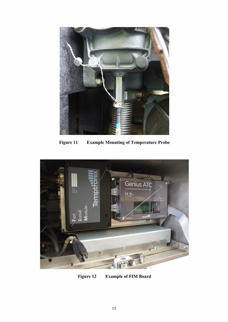
Figure 11 Example Mounting of Temperature Probe
Figure 12 Example of FIM Board
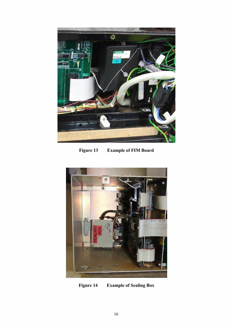
Figure 13 Example of FIM Board
Figure 14 Example of Sealing Box
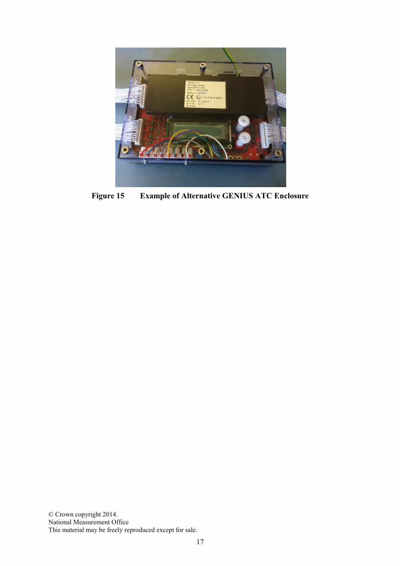
Figure 15 Example of Alternative GENIUS ATC Enclosure

3
Descriptive Annex
1 INTRODUCTION
The GENIUS ATC conversion device, which may be used with up to four metering units,
corrects the volume of fuel, measured at base conditions, to an indicated volume at reference
conditions (15°C). The Automatic Temperature Compensation (ATC) function is added by
connecting the ATC unit between the output from the dispenser pulser and the input to the
dispenser calculator. The ATC counts the number of pulses received from the measurement
transducer(s), measures the product temperature and uses these measured values and a stored
reference density value (kg/m³) to calculate the volume at reference conditions. The ATC
sends out a number of impulses that is representative for the converted volume, to the
connected calculating and indicating device. The temperature measurement is provided by a
temperature probe, fitted into the supply pipework, located as close as possible to the meter.
The volume at metering conditions, the product temperature and the selected reference
density can be displayed on an inspection display that is fitted to the ATC unit.
2 CONSTRUCTION
2.1 Main Board
The Genius ATC main board is roughly divided into four quadrants. These correspond to the
two (hose) sides (A + B) of a dispenser and the compensated and uncompensated portions of
the circuit. The board contains:
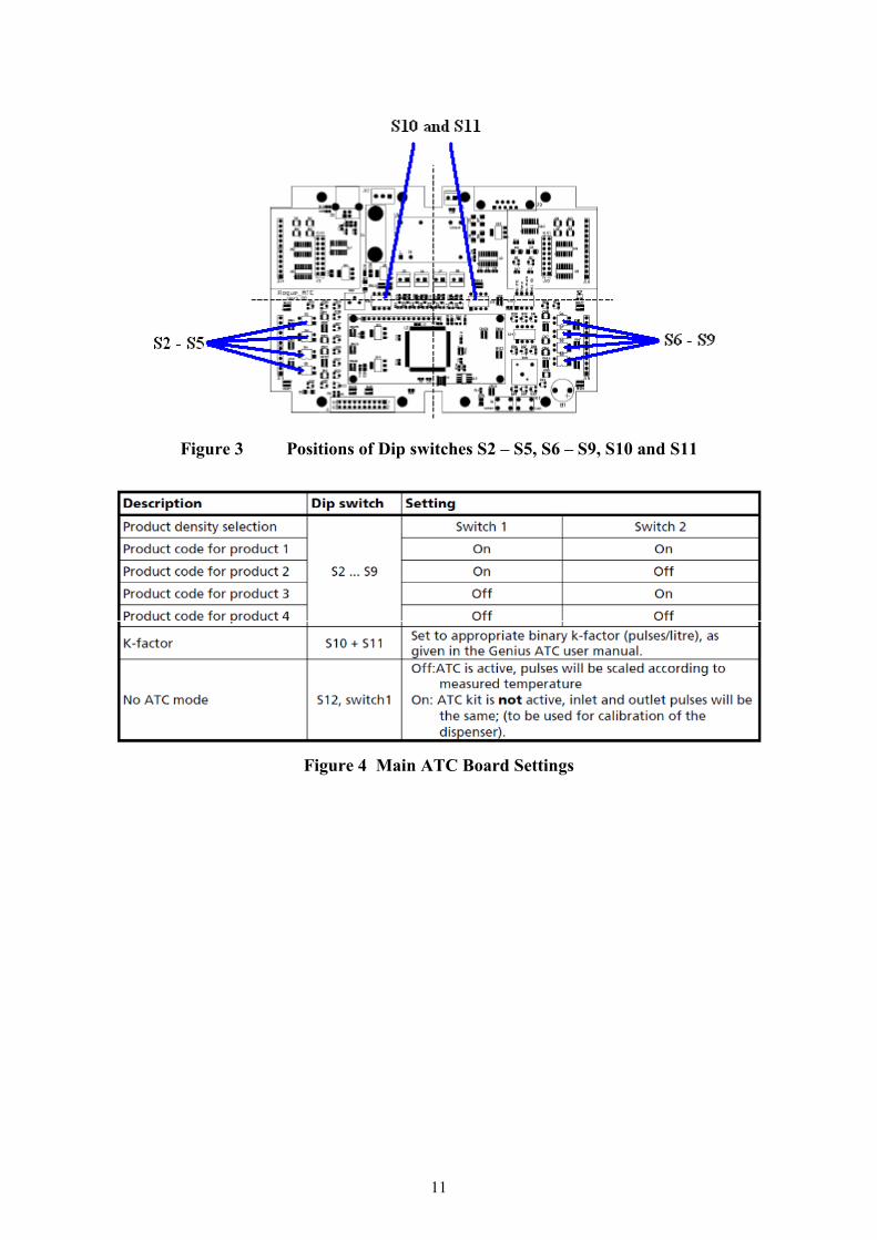
• dip switches S2-S5, S6-S9, S10 and S11, which are used to set the device.
• dip switch S12, which is used to set the optional “Mode” features:
o No ATC, (spare),
o LCD Alarm Off and
o Buzzer Alarm Off
o Programming Mode
• an on-board power supply that allows it to be powered directly from a mains
voltage source (100Vac to 260Vac).
• a 16 x 2 character LCD display that provides the user with information. The
display is backlit and can be equipped with an optional screen heater to allow for
visibility down to -40 °C.
• Calibration and Reset switches.
• Function select (positions 1-5) rotary knob and function activate button
2.1.1 Function select
• position 1: Side A + Side B Total. This setting displays the compensated and
uncompensated values for all fuel that has flown through the
dispenser. It sums up all compensated and uncompensated volumes,
regardless of density or product.

4
• position 2: Totals Product 1 – 4. This setting shows the compensated and
uncompensated volumes for each individual product. Each product is
shown for a few seconds and then the next product information is
shown in a cycle. The cycle can be stopped at any time by pushing the
red Function button. Pushing the button again will begin the cycling
again.
• position 3: Last Fill Information. This setting displays the compensated and
uncompensated data from the last fill for side A and side B of the
dispenser.
• position 4: Product Densities. This setting shows the current product densities
for each grade on side A and side B.
• position 5: Product Temperatures. This setting displays the current temperatures
as measured by the temperature probes.
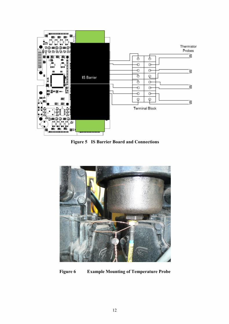
2.2 IS Barrier Board
The Intrinsically Safe (IS) ATEX approved barrier board is mounted above the main board
inside the ATC enclosure. The IS barrier is encapsulated in a black epoxy (Hysol) for ATEX
compliance, and is spatially divided into safe and unsafe zones. The probe wires emanate
from the epoxy and are connected to the thermistor probe(s) via a terminal block mounted on
the enclosure.
2.3 Software
The software version number, 1.09, is shown on the ATC’s inspection display during start-
up.
The software is not divided into two parts, i.e. Weights and Measures and non-Weights and
Measures.
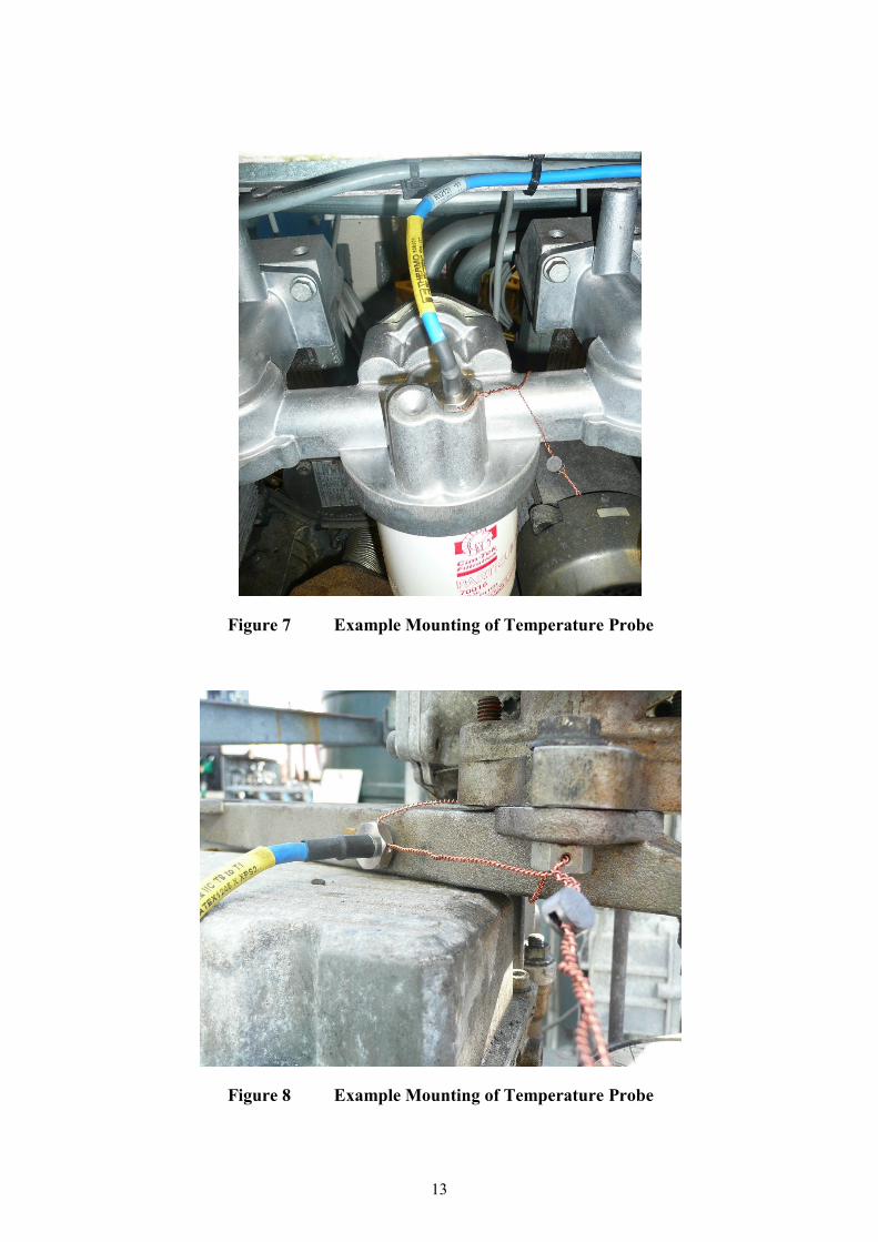
2.4 Temperature Probes
2.4.1 The probe is a type W199-4 ATEX. The probe is positioned in the most
practicable location for the dispenser type, which can include the discharge side of the
pumping unit to the meter inlet(s), or in the pipework between the pump unit and meter(s).
Examples of the most common installations are in Figures 6, 7, 8, 9, 10, & 11. An optional
Thermal Test Well may be located adjacent to the probe for use with another temperature
sensor, in checking that the probe is operating correctly. Where this Test Well is fitted, it
shall be covered with a plug to prevent dirt entering the Test Well. The W199-4 temperature
probe is connected to the IS barrier board.
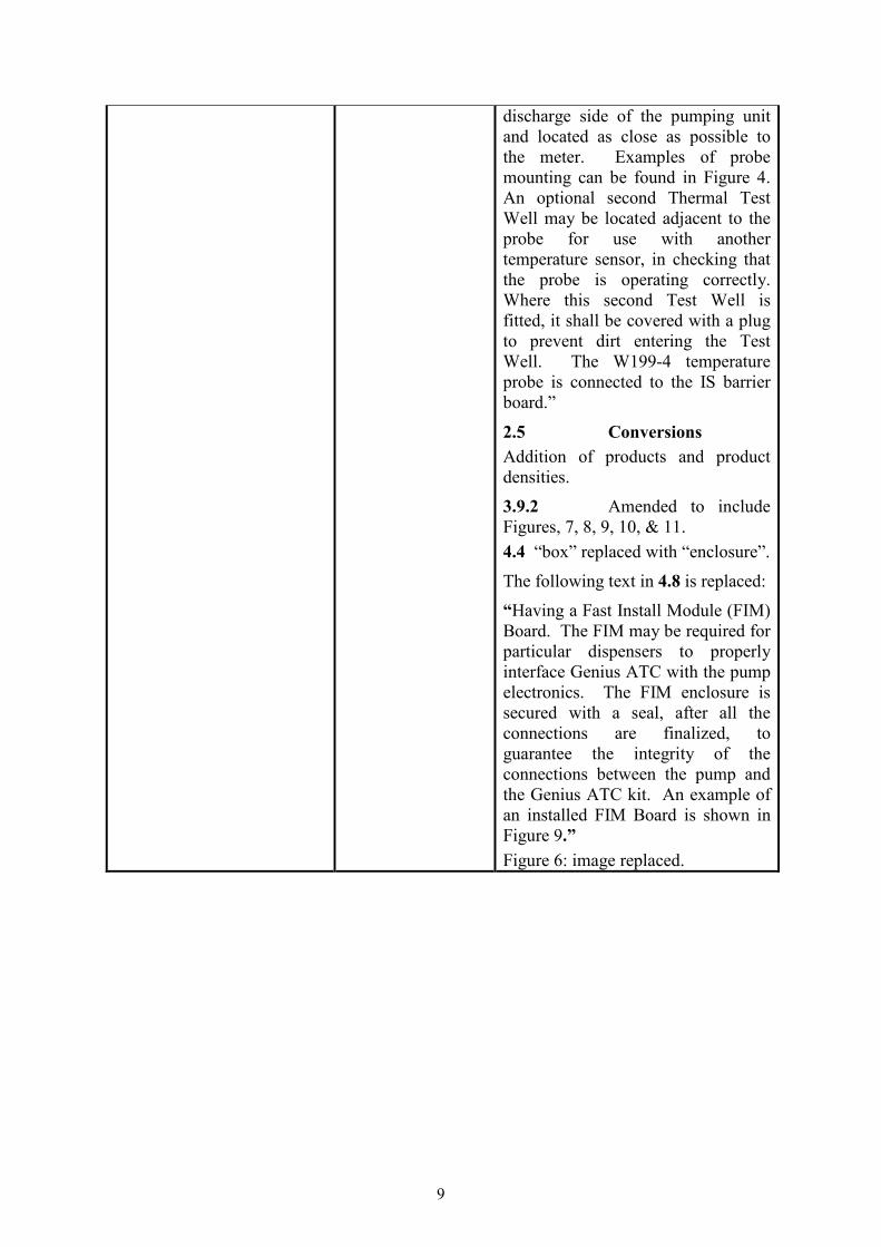
2.5 Conversions
The ATC can perform conversion calculations according to the following methods:
• API MPMS Chapter 11;
• ASTM table D1250-04, 54B (Refined Petroleum Products)
The conversion is based on the measured volume at metering conditions, the measured
product temperature and a stored product reference density value (kg/m3). The product
reference density is the density at a product temperature of 15 °C.
5
The following product densities are available:
Petrol Unleaded Premium - 730 kg/m3
Petrol Unleaded Super - 736 kg/m3
Diesel - 839 kg/m3
Gas Oil & Marine Diesel - 853 kg/m3
Other Product Density - Input any value from 500 kg/m3 to 999 kg/m3
3 OPERATION
3.1 The GENIUS ATC incorporates a Universal Pulse Adapter, which is a digital
algorithm that can detect the pulser pattern and emulate it at the output so that little
configuration is required and no hardware adapters are required. The system counts the
number of pulses received from the measurement transducers, impulse encoders (level A as
per API chapter 5 section 5, double channel, 90° phase shift), measures the product
temperature and uses these measured values and a stored reference density value (kg/m³) to
calculate the volume at reference conditions. The ATC sends out a number of impulses, that
is representative of the converted volume, to the calculating and indicating device.
3.2 The program code and conversion tables are stored during normal use in the
unchangeable EPROM. They are protected against errors with a 16 bit checksum. The
appropriate portions of the EPROM are summed directly after the start of every transaction
on either the A or B side of the dispenser. In addition to protection against changes of the
EPROM the system checks against loss of processor clock and program continuity (watchdog
timer). Any of these errors will cause the ATC unit to send “bad pulse” streams to the
connected dispenser’s calculating and indicating device, to trigger an error and abort any
active transactions. This has the effect of disallowing any new or current transactions on
either side of the dispenser. The ATC display will also show an error at this time.
This condition will continue until power of the ATC unit is cycled.
3.3 The volume at metering conditions, the product temperature and the selected
product reference density values can be viewed on the display that is fitted to the ATC unit
main board.
3.4 The temperature sensor cable is connected into the ATC via the IS barrier. A
maximum of 4 temperature probes can be connected.
3.5 The configuration of the calculating and indicating device, and the position of
the dipswitches, is given in Figure 4.
3.6 Selectable presentations on the display
• Volume at metering conditions.
• Measured product temperature.
• Selected reference density.
• Error codes.

6
3.7 Error Messages
Error message will alternate at 2 second intervals with the information selected by the
switches.
Prob = Probe Error
Puls = Pulse Error
Priority of error is as shown above, when both errors are detected, i.e. a Probe and a Pulse
error, only “Prob” will be indicated.
When nozzle is activated, the display could show following code:
OFF = ATC Compensation is disabled
Any known defects are detected by the ATC software and a routine shut down occurs. An
error signal is sent to the dispenser. Any corruption of software results in the same error
signal and shut down.
3.8 Software version check
The software version can be checked by cycling the power to the unit. The software version
will be shown for 2 seconds on the ATC display, after this the temperature will be shown.
3.9 Securing
3.9.1 The ATC enclosure is secured with a seal. After all switches have been set to
their correct position, the module’s enclosure shall be sealed against opening.
The enclosure may vary so the figure is an example for guidance purposes.
3.9.2 The temperature probe is secured, to prevent its removal (Figures 6, 7, 8, 9, 10,
& 11).
4 CONDITIONS
4.1 For dispensers providing temperature compensation, the primary indicator
(dispenser display) shall clearly indicate that the volume dispensed is corrected to 15 °C.
4.2 When this ATC is part of a fuel dispenser or LPG measuring device, the
minimum measured quantity of that fuel dispenser, or LPG measuring device, shall be clearly
indicated as being 2 litres minimum delivery*.
* The minimum delivery level may alternatively be 5 litres.
4.3 The ATC unit shall be powered from the calculating and indicating device to
which it is connected. Under no circumstances should the ATC power supply voltage fall
below 5,0 V DC.
4.4 The temperature sensor cable shall be connected directly to the ATC
enclosure.
4.5 The use of this Supplement Certificate is limited to only those 3rd parties who
have obtained written permission from Temptronix Inc., Canada.
7
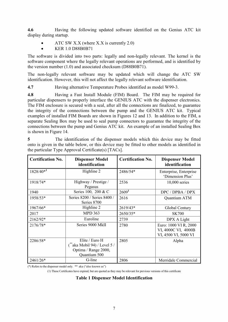
4.6 Having the following updated software identified on the Genius ATC kit
display during startup.
• ATC SW X.X (where X.X is currently 2.0)
• KER 1.0 D88B0B71
The software is divided into two parts: legally and non-legally relevant. The kernel is the
software component where the legally relevant operations are performed, and is identified by
the version number (1.0) and associated checksum (D88B0B71).
The non-legally relevant software may be updated which will change the ATC SW
identification. However, this will not affect the legally relevant software identification.
4.7 Having alternative Temperature Probes identified as model W99-3.
4.8 Having a Fast Install Module (FIM) Board. The FIM may be required for
particular dispensers to properly interface the GENIUS ATC with the dispenser electronics.
The FIM enclosure is secured with a seal, after all the connections are finalized, to guarantee
the integrity of the connections between the pump and the GENIUS ATC kit. Typical
examples of installed FIM Boards are shown in Figures 12 and 13. In addition to the FIM, a
separate Sealing Box may be used to seal pump connectors to guarantee the integrity of the
connections between the pump and Genius ATC kit. An example of an installed Sealing Box
is shown in Figure 14.
5 The identification of the dispenser models which this device may be fitted
onto is given in the table below, or this device may be fitted to other models as identified in
the particular Type Approval Certificate(s) [TACs].
Certification No. Dispenser Model
identification
Certification No. Dispenser Model
identification
1828/40*1 Highline 2 2486/54* Enterprise, Enterprise
‘Dimension Plus’
1918/74* Highway / Prestige /
Pegasus 2536 10,000 series
1940 Series 100, 200 & C 26091 DPC / DPBA / DPX
1958/53* Series 8200 / Series 8400 /
Series 8700 2616 Quantium ATM
1967/66* Highline 2 2619/43* Global Century
2017 MPD 363 2650/35* SK700
2162/92* Euroline 2739 DPX A Light
2176/78* Series 9000 MkII 2780 Euro: 1000 VI R, 2000
VI, 4000C VI, 4000B
VI, 4500 VI, 5000 VI
2286/58* Elite / Euro H
(**aka Mobil 94) / Level 5 /
Optima / Range 2000,
Quantium 500
2805 Alpha
2461/26* G-line 2806 Merridale Commercial
(*) Refers to the dispenser model only. ** aka (“also known as”)
(1) These Certificates have expired, but are quoted as they may be relevant for previous versions of this certificate
Table 1 Dispenser Model Identification
8
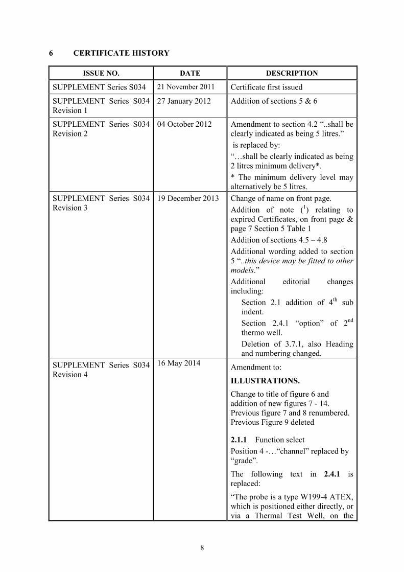
6 CERTIFICATE HISTORY
ISSUE NO. DATE DESCRIPTION
SUPPLEMENT Series S034 21 November 2011 Certificate first issued
SUPPLEMENT Series S034
Revision 1
27 January 2012 Addition of sections 5 & 6
SUPPLEMENT Series S034
Revision 2
04 October 2012 Amendment to section 4.2 “..shall be
clearly indicated as being 5 litres.”
is replaced by:
“…shall be clearly indicated as being
2 litres minimum delivery*.
* The minimum delivery level may
alternatively be 5 litres.
SUPPLEMENT Series S034
Revision 3
19 December 2013 Change of name on front page.
Addition of note (1) relating to
expired Certificates, on front page &
page 7 Section 5 Table 1
Addition of sections 4.5 – 4.8
Additional wording added to section
5 “..this device may be fitted to other
models.”
Additional editorial changes
including:
Section 2.1 addition of 4th sub
indent.
Section 2.4.1 “option” of 2nd
thermo well.
Deletion of 3.7.1, also Heading
and numbering changed.
SUPPLEMENT Series S034
Revision 4
16 May 2014 Amendment to:
ILLUSTRATIONS.
Change to title of figure 6 and
addition of new figures 7 - 14.
Previous figure 7 and 8 renumbered.
Previous Figure 9 deleted
2.1.1 Function select
Position 4 -…“channel” replaced by
“grade”.
The following text in 2.4.1 is
replaced:
“The probe is a type W199-4 ATEX,
which is positioned either directly, or
via a Thermal Test Well, on the
9
discharge side of the pumping unit
and located as close as possible to
the meter. Examples of probe
mounting can be found in Figure 4.
An optional second Thermal Test
Well may be located adjacent to the
probe for use with another
temperature sensor, in checking that
the probe is operating correctly.
Where this second Test Well is
fitted, it shall be covered with a plug
to prevent dirt entering the Test
Well. The W199-4 temperature
probe is connected to the IS barrier
board.”
2.5 Conversions
Addition of products and product
densities.
3.9.2 Amended to include
Figures, 7, 8, 9, 10, & 11.
4.4 “box” replaced with “enclosure”.
The following text in 4.8 is replaced:
“Having a Fast Install Module (FIM)
Board. The FIM may be required for
particular dispensers to properly
interface Genius ATC with the pump
electronics. The FIM enclosure is
secured with a seal, after all the
connections are finalized, to
guarantee the integrity of the
connections between the pump and
the Genius ATC kit. An example of
an installed FIM Board is shown in
Figure 9.”
Figure 6: image replaced.

10
Figure 1 GENIUS ATC and Enclosure
Figure 2 Schematic of ATC Main Board, and Connections
11
Figure 3 Positions of Dip switches S2 – S5, S6 – S9, S10 and S11
Figure 4 Main ATC Board Settings
12
Figure 5 IS Barrier Board and Connections
Figure 6 Example Mounting of Temperature Probe
13
Figure 7 Example Mounting of Temperature Probe
Figure 8 Example Mounting of Temperature Probe

14
Figure 9 Example Mounting of Temperature Probe
Figure 10 Example Mounting of Temperature Probe
15
Figure 11 Example Mounting of Temperature Probe
Figure 12 Example of FIM Board
16
Figure 13 Example of FIM Board
Figure 14 Example of Sealing Box
© Crown copyright 2014.
National Measurement Office
This material may be freely reproduced except for sale.
17
Figure 15 Example of Alternative GENIUS ATC Enclosure