supplemental restraint system - Клуб МАЗДА material for technician/ct-l10… · • all...
TRANSCRIPT
TRAINING MANUAL CT-L1003
Supplemental Restraint System

No part of this hardcopy may be reproduced in any form without prior permission of Mazda Motor Europe GmbH. The illustrations, technical information, data and descriptive text in this issue, to the best of our knowledge, were correct at the time of going to print. No liability can be accepted for any inaccuracies or omissions in this publication, although every possible care has been taken to make it as complete and accurate as possible. © 2005 Mazda Motor Europe GmbH Training Services
Suppl. Restraint System Table of Contents
Introduction .......................................................................................00-1 Overview ............................................................................................01-1
Fundamentals ........................................................................................... 01-1 Parts Location ........................................................................................... 01-2 Directives for Working on SRS.................................................................. 01-3
Components ......................................................................................02-1
SAS Module .............................................................................................. 02-1 SRS Warning Light ................................................................................... 02-3 Crash Zone Sensor................................................................................... 02-5 Side Airbag Sensors ................................................................................. 02-7 Clock Spring............................................................................................ 02-10 Buckle Switch.......................................................................................... 02-11 Seat Track Position Sensor..................................................................... 02-11 Driver Front Airbag.................................................................................. 02-13
Dual-Stage Airbag ............................................................................ 02-16 Passenger Front Airbag .......................................................................... 02-18
System Using Highly Compressed Gas............................................ 02-19 Side Airbag ............................................................................................. 02-22 Curtain Airbag ......................................................................................... 02-24 Connectors in Trigger Circuit .................................................................. 02-26 Seatbelt................................................................................................... 02-27
Emergency Locking Retractor .......................................................... 02-29 ELR Release Function...................................................................... 02-31 Automatic Locking Retractor............................................................. 02-34 Belt Pretensioner .............................................................................. 02-35 Rack-Operated Belt Pretensioner ..................................................... 02-36 Ball-Operated Belt Pretensioner ....................................................... 02-39 Rotor-Operated Belt Pretensioner .................................................... 02-41 Buckle-Operated Belt Pretensioner .................................................. 02-43 Belt Force Limiter.............................................................................. 02-45 Seatbelt Inspection ........................................................................... 02-46
Passenger Airbag Deactivation System.................................................. 02-47 PAD Retrofitting ................................................................................ 02-49
Occupant Classification System.............................................................. 02-50 Passenger Occupancy Detection System......................................... 02-50 Occupancy Classification System Used on Mazda Tribute Facelift .. 02-53
Mazda Vehicles and their SRS Components .......................................... 02-56
Curriculum Training

Table of Contents Suppl. Restraint System
Operation ...........................................................................................03-1 Parts Location ........................................................................................... 03-1 Frontal Collision ........................................................................................ 03-2 Side Impact ............................................................................................... 03-3 Wiring Diagram ......................................................................................... 03-4
Diagnosis and Repair........................................................................04-1 On-Board Diagnostic System.................................................................... 04-1 OBD System of the 2nd Generation ........................................................... 04-2
Present Malfunctions .......................................................................... 04-2 Past Malfunctions ............................................................................... 04-3
OBD of the 3rd Generation ........................................................................ 04-4 Present and Past Malfunctions ........................................................... 04-5 PID Monitor Function .......................................................................... 04-7 Simulation Test Function .................................................................... 04-8 Additional Diagnostic Items ................................................................ 04-8 Troubleshooting Example ................................................................... 04-9
SRS Component Replacement ............................................................... 04-14 Side Airbag Sensor Replacement on the Mazda3 / RX-8 ................. 04-14 SAS Module...................................................................................... 04-15 SAS Module Replacement (2nd SRS Generation)............................. 04-15 SAS Module Replacement with WDS (3rd SRS Generation)............. 04-16 Manual Module Configuration........................................................... 04-17
List of Abbreviations.........................................................................05-1
Curriculum Training

Supp. Restraint System Introduction
Introduction
• With the introduction of seatbelts as an occupant restraint system for all passenger cars the number of people subjected to serious injury or death has been dramatically reduced. As a further result, the customers and the authorities asked for more safety systems and the car manufacturers developed them accordingly to provide more safety to the customers. One of those systems is the so-called SRS (Supplemental Restraint System) that assists the seatbelts in restraining the occupants in case of an accident.
• Mazda’s SRS features one ore more of the following additional restraint systems:
– Front airbags
– Side airbags
– Curtain airbags
– Pretensioners
• All Mazda vehicles that are currently sold in Europe are equipped with a SRS consisting of at least front airbags on the driver and passenger side. Some vehicles are equipped with up to six airbags in total.
• The skills needed to diagnose and repair SRS related concerns require comprehensive system knowledge, because any mistake can lead to serious injury or death of the occupants, or even of the technician who works on the system. This course is a theoretical and practical guide to gain general and Mazda specific knowledge about the various SRS, i.e. their components, function and diagnosis.
• Any person associated with the diagnosis and repair of SRSs must have the knowledge to deliver a “Fix it right first time” repair. Therefore, the Mazda Masters Development and Qualification path provides the following training course required for the service on SRSs:
– Supplemental Restraint System CT-L1003
• The ranking of this course within the Mazda Masters educational system is Level 1 – ‘Mazda Technician’. It is focused on technicians that have already experience in maintaining and repairing Mazda vehicles and have previously attended the courses “New-To-Mazda” CT-L1001 and “Basic Electrics” CT-L1004.
Curriculum Training 00-1

Introduction Suppl. Restraint System • The training manual “Supplemental Restraint System” is divided into the following main
chapters:
– Overview
– Components
– Operation
– Diagnosis and Repair NOTE: The data, tables and procedures represented in this training manual serve only as
examples. They are taken from the service literature and subjected to major or minor changes in the course of time. To prevent any mis-diagnosis refer always to the current service literature while working on SRSs.
00-2 Curriculum Training

Suppl. Restraint System Overview
Overview
Fundamentals
• Nowadays all vehicles are equipped with a SRS in order to ensure optimum protection of the occupants in case of an accident.
• An airbag achieves the best possible effect in conjunction with the seatbelt and is triggered only in case of a serious accident, in which the safety of the occupants cannot be guaranteed by the seatbelts alone. Therefore, it is designed to reduce the occupant’s forward movement in a controlled manner in order to reduce force applied to the body and organs.
• This training manual explains SRS components and systems used on the current Mazda vehicles (European specification only) and their predecessors, as well as the appropriate diagnostic and installation procedures.
NOTE: Before starting the diagnosis or repair of the SRS, always check whether any service
information relevant to the malfunction has been published. • Additional information about the current SRS can be found in the following sections of the
respective W/M:
– Section “T” in the W/M with former layout.
– Section “Restraints” in the W/M on the CD-ESI.
– Section 5: “Body and Paint” ”Supplemental Restraint System” – on the service manual CD for Mazda2.
– Respective W/D (Wiring Diagram)
Curriculum Training 01-1

Overview Suppl. Restraint System Parts Location
• The picture on the next page is an example and shows the SRS components of the Mazda6. The SRS can consist of the following components (not all vehicles are equipped with all components):
– Seat track postion sensor
– Buckle switches
– Passenger airbag deactivation system or occupant classification system
– Crash zone sensor
– Side airbag sensors
– SAS (Sophisticated Airbag Sensor) module
– Passenger airbag cut-off indicator light
– SRS warning light
– Clock spring
– Driver and passenger front airbags
– Side airbags
– Curtain airbags
– Pretensioners NOTE: Each gas generator features a sticker with barcode, order number and serial number.
Thus it is possible to track the component throughout its production, installation and service life.
01-2 Curriculum Training

Suppl. Restraint System Overview
1003_106
1 SRS warning light 7 Side airbag sensor 2 Clock spring 8 Belt pretensioner 3 Passenger front airbag 9 Side airbag 4 Crash zone sensor 10 Occupancy sensor 5 SAS module 11 Curtain airbag 6 Passenger airbag deactivation indicator
light 12 Driver front airbag
Directives for Working on SRS
• When working on the SRS always follow carefully the directives and warnings stated in the W/M and in this training manual. It is also mandatory to comply with the specific national requirements concerning explosive material handling.
• The work on SRS must be carried out by skilled professional personnel, who are familiar with the safety regulations and who take special measures to ensure that these are followed. The relevant rules and directives must be observed, especially regarding:
– Directives of the responsible authorities
– Accident prevention
– Environment protection
– Storage of the components
Curriculum Training 01-3
Overview Suppl. Restraint System • When handling SRS components the following points should be observed:
– SRS components can accidentally deploy during related work or bodywork (such as welding, dent repair etc.). Never disconnect components before the system is secured against unintentional triggering. Therefore, depower the SRS according to the related W/M to avoid serious injury or death.
– Always disconnect the battery before welding to avoid unintentional triggering of SRS components.
– Non-triggered SRS components must not be littered. They must be shipped back to the manufacturer in the original component packaging. The sender has to inform the shipping company of the explosive content and the components must not be shipped by postal service.
– If pyrotechnic residue from SRS components contacts the eyes, immediately wash the eyes thoroughly with clean water and seek medical assistance.
– If a large amount of pyrotechnic residue is inhaled, seek medical assistance.
– When handling deployed SRS components, wear safety gloves and glasses to protect your skin and eyes from being irritated due to pyrotechnic residue.
– The propellant inside of the SRS components is self-ignited at an ambient temperature of about 175° C.
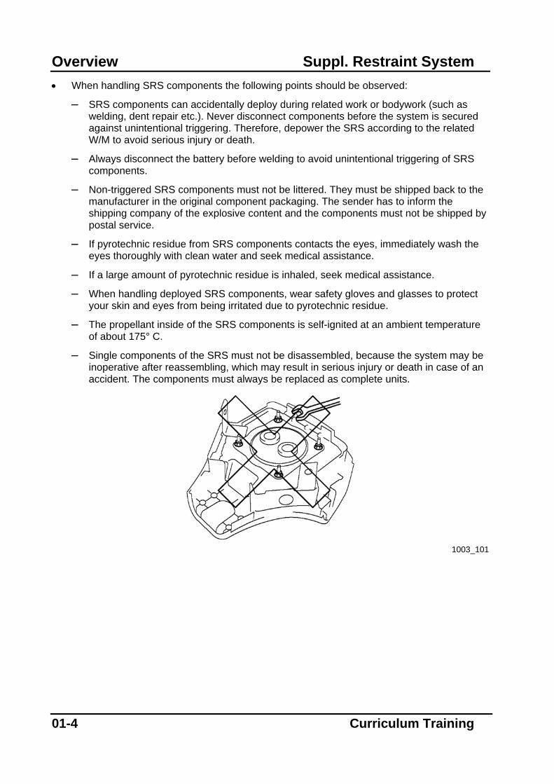
– Single components of the SRS must not be disassembled, because the system may be inoperative after reassembling, which may result in serious injury or death in case of an accident. The components must always be replaced as complete units.
1003_101
01-4 Curriculum Training

Suppl. Restraint System Overview – If a problem is found in the SRS wiring, always follow the procedures of the
corresponding W/M for the repair sequence. A wiring harness that is incorrectly repaired may result in an airbag or pretensioner not being deployed or being deployed accidentally, leading to serious injury or death.
1003_102
– An ohmmeter must not be used to inspect an airbag or pretensioner, because it can
deploy the component, what may result in serious injury or death. Always use the on-board diagnostic function to diagnose an airbag or pretensioner for malfunctions.
1003_103
Curriculum Training 01-5
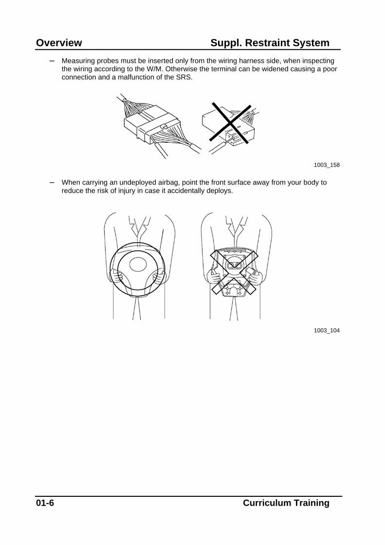
Overview Suppl. Restraint System – Measuring probes must be inserted only from the wiring harness side, when inspecting
the wiring according to the W/M. Otherwise the terminal can be widened causing a poor connection and a malfunction of the SRS.
1003_158
– When carrying an undeployed airbag, point the front surface away from your body to
reduce the risk of injury in case it accidentally deploys.
1003_104
01-6 Curriculum Training

Suppl. Restraint System Overview – An undeployed airbag must not be placed face down on its surface. Because if it
deploys, the motion of the airbag may result in serious injury or death. Therefore, always face the front surface up to reduce the motion of the airbag in case it accidentally deploys.
– Do not store anything on top of an undeployed airbag.
1003_105
Curriculum Training 01-7

Overview Suppl. Restraint System Notes:
01-8 Curriculum Training
Suppl. Restraint System Components
Components
SAS Module
• The SAS (Sophisticated Airbag Sensor) module is located in the center console area and is the core component of the SRS. As the name states, it features at least one sensor that is engineered to detect situations requiring SRS activation. Furthermore, it incorporates the control module for the SRS.
• The sensor itself is an accelerometer built into a microchip (or a similar type). Modern modules incorporate a crash sensor and a saving sensor. The saving sensor may operate both mechanically or electronically and is used to prevent unintended triggering of the airbag e.g. due to electromagnetic interference.
• The SAS module is connected to all SRS related components and is programmed with vehicle-specific parameters. It decides whether or not it is necessary to trigger components of the SRS. The decision is based on the input signals, its own sensor measurements and stored reference values. Furthermore it decides which of the components must be triggered.
• If the crash sensor and the corresponding saving sensor detect a crash event, the SAS module decides within a few milliseconds whether and which component has to be triggered. Depending on crash severity and other values the front airbags and seat belt pretensioners are triggered about 10 ms after a front impact, while the curtain airbag and side airbag are triggered about 3 ms after a side impact.
• The SAS features an integrated back-up power supply to provide the system with power even if the vehicle power supply should fail (e.g. if the vehicle battery should be disconnected in an accident). This back-up power supply ensures the SRS operation for at least 150 ms after the vehicle power supply is interrupted.
• If the SAS module decides to trigger SRS components, it sends a corresponding AC (Alternating Current) or DC (Direct Current) signal (depending on the vehicle type) to the respective component.
• The SAS module is equipped with a DTC (Diagnostic Trouble Code) memory, and features the possibility to diagnose the system with the aid of the WDS (Worldwide Diagnostic System) via the DLC 2 (Data Link Connector) or via the DLC 1 (depending on the vehicle type) and the SRS warning light.
Curriculum Training 02-1
Components Suppl. Restraint System
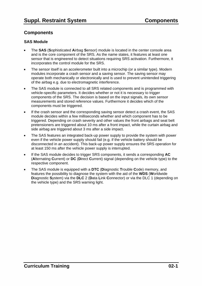
NOTE: The mounting bolts of the SAS module must always be tightened to the specified torque in the compulsory sequence (refer to W/M). Ensure that the module is correctly aligned, otherwise the measurement results for the acceleration might be affected, causing a malfunction of the SRS.
1003_107
1 Bolt 3 SAS module 2 Connector
02-2 Curriculum Training
Suppl. Restraint System Components
SRS Warning Light
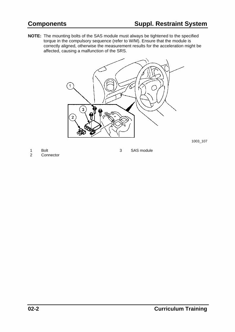
• The SRS warning light is located in the instrument cluster. If the SAS module detects a fault, the SRS warning light flashes or illuminates.
• If an open circuit exists in the cable connection between the SRS warning light and the SAS module, the warning light will be automatically illuminated by the internal control circuit of the instrument cluster.
NOTE: The overall SRS or some of its components may remain operational even when the
SRS warning light flashes or is illuminated. • Depending on the vehicle, a malfunction of the SRS warning light is indicated by a
warning buzzer.
1003_162
1 SRS warning light
Curriculum Training 02-3

Components Suppl. Restraint System
• The picture below is an excerpt from the Mazda3 W/D and shows the SRS warning light in the instrument cluster.
1003_176
02-4 Curriculum Training
Suppl. Restraint System Components
Crash Zone Sensor
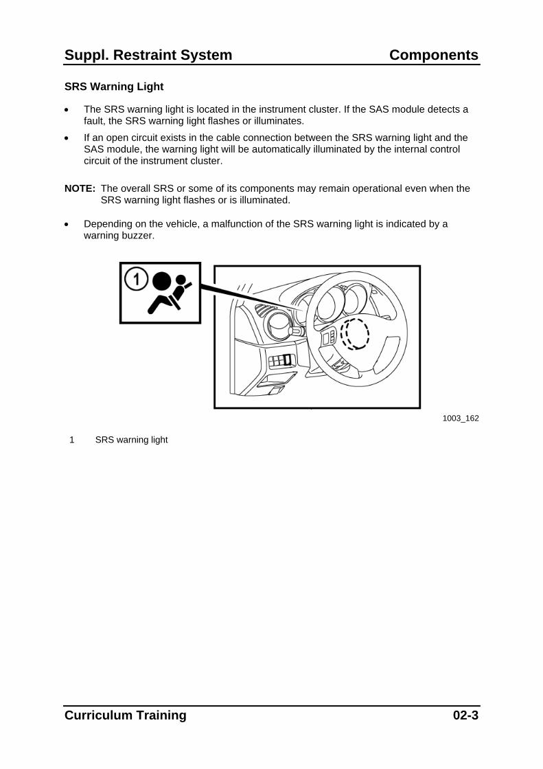
• Not all vehicles are equipped with a crash zone sensor, but it is mandatory if the vehicle is equipped with dual stage airbags. It is mounted at the front of the vehicle to determine type (direction) and severity of a frontal impact as early as possible. Furthermore its signal helps the SAS module to distinguish between crash and non-crash events. Thus it prevents the SRS components from being triggered when the vehicle touches bumps, curbs etc. while driving.
• It incorporates an accelerometer and is connected to the SAS module. NOTE: The bolt(s) of the crash zone sensor must always be tightened to the specified
torque (refer to W/M). Ensure that the sensor is correctly aligned, otherwise the measurement results for the acceleration might be affected, causing a malfunction of the SRS.
1003_108
1 Bolt 3 Connector 2 Cover 4 Crash zone sensor
Curriculum Training 02-5

Components Suppl. Restraint System
• The pictures below, shows a functional overview of a crash zone sensor used on MX-5 (NB).
1003_163
1 SAS module 3 Crash zone sensor (not activated) 2 Evaluation circuit 4 Accelerometer
1003_164
1 Impact force 4 Evaluation circuit 2 Activation signal 5 Current flow 3 SAS module 6 Crash zone sensor (activated)
02-6 Curriculum Training

Suppl. Restraint System Components
Side Airbag Sensors
• Side airbag sensors are only used in vehicles with side airbags and/or curtain airbags. They are mounted close to each B-pillar in order to determine severity of a side impact. The Tribute (EP) FL (Face Lift) is equipped with an additional side airbag sensor at each C-pillar to ensure optimum protection for the occupants even if a side impact occurs at the rear of the vehicle. The additional sensor is necessary, because of rotation of the vehicle about the vertical axis an impact in the rearward area of the vehicle would not be recognized by the front side sensors.
• It incorporates an accelerometer and is connected to the SAS module.
• Mazda uses two different types of side airbag sensors. One type features an integrated saving sensor and triggers the corresponding side airbag directly via the SAS module. The other sensor type detects the impact severity and sends a corresponding signal to the SAS module where then the decision is made whether or not the corresponding side/curtain airbag have to be triggered.
NOTE: The bolt of the side airbag sensor must always be tightened to the specified torque
(refer to W/M). Ensure that the sensor is correctly aligned, otherwise the measurement results for the acceleration might be affected, causing a malfunction of the SRS.
1003_109
1 Connector 3 Bolt 2 Side airbag sensor
Curriculum Training 02-7
Components Suppl. Restraint System
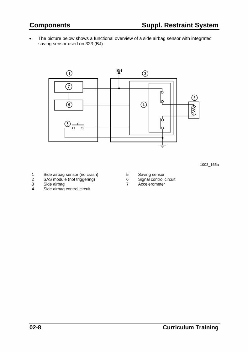
• The picture below shows a functional overview of a side airbag sensor with integrated saving sensor used on 323 (BJ).
1003_165a
1 Side airbag sensor (no crash) 5 Saving sensor 2 SAS module (not triggering) 6 Signal control circuit 3 Side airbag 7 Accelerometer 4 Side airbag control circuit
02-8 Curriculum Training

Suppl. Restraint System Components
1003_165b
1 Side airbag sensor (during side impact) 6 Signal control circuit 2 SAS module (triggering the side airbag) 7 Accelerometer 3 Side airbag 8 Current flow (triggering the side airbag) 4 Side airbag control circuit 9 Side impact signal 5 Saving sensor (closed)
Curriculum Training 02-9

Components Suppl. Restraint System
Clock Spring
• The clock spring is a spiral ribbon cable, located inside a housing between the steering wheel and steering column. It serves as electrical connection between the driver front airbag and the vehicle wiring harness.
• When the steering wheel is turned, the clock spring can “wind up” and “unwind”, so that electrical contact constantly exists between the airbag and the SAS module.
1003_149
1 Clock spring 4 Steering wheel 2 Spring wire 5 Steering wheel turned to the left 3 Wiring harness 6 Steering wheel turned to the right
NOTE: The clock spring must be properly aligned when servicing (refer to W/M). Otherwise
it can be easily damaged, causing a malfunction of the SRS.
1003_109a
1 Clock spring 3 Airbag connectors 2 Screw 4 Wiring harness connector
02-10 Curriculum Training
Suppl. Restraint System Components
Buckle Switch
• Some vehicles are equipped with buckle switches for either one or both front seat belts. They are connected either to the instrument cluster or to the SAS module and serve to remind the driver/passenger to fasten the seatbelt.
• On Mazda vehicles with buckle switches connected to the SAS module the module transmits the status of the buckle switch via CAN (Controller Area Network) to the instrument cluster.
Seat Track Position Sensor
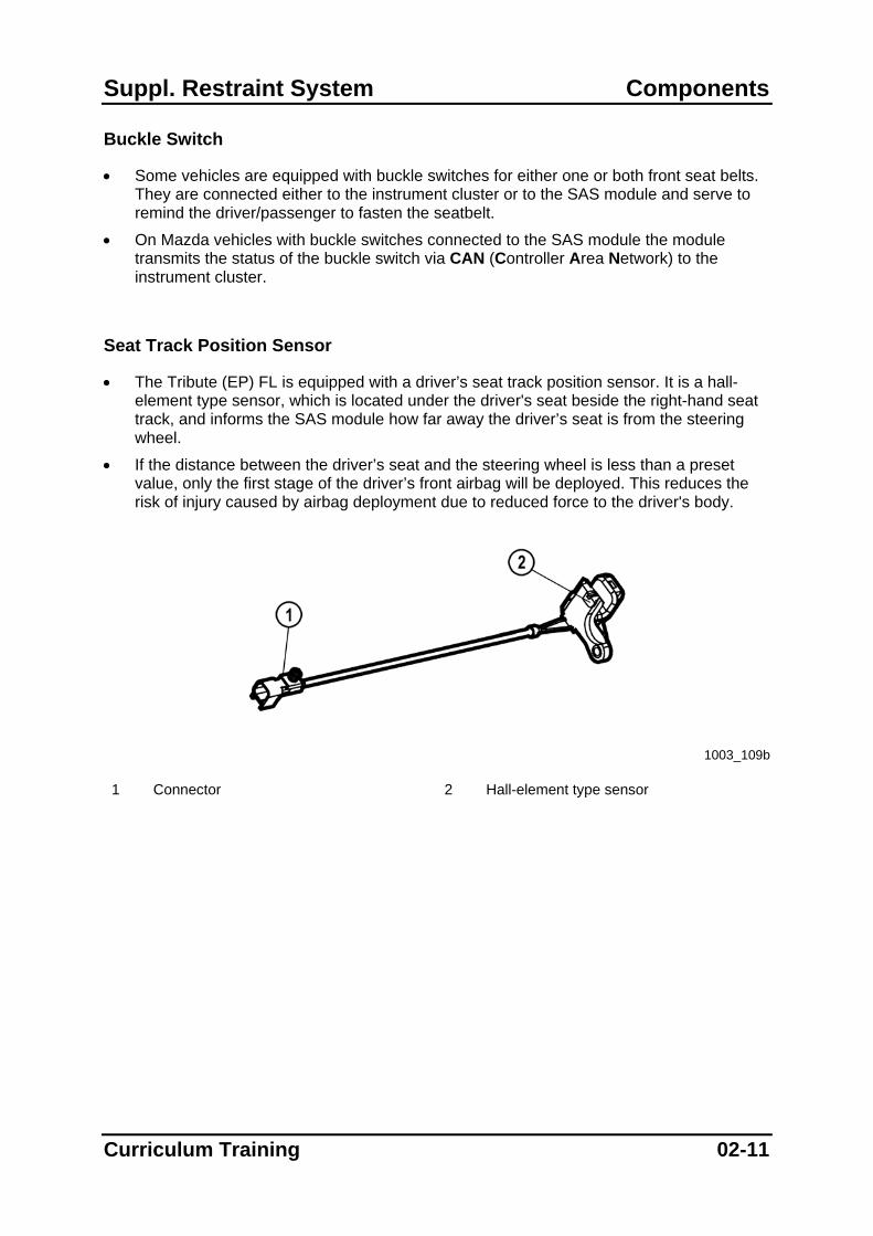
• The Tribute (EP) FL is equipped with a driver’s seat track position sensor. It is a hall-element type sensor, which is located under the driver's seat beside the right-hand seat track, and informs the SAS module how far away the driver’s seat is from the steering wheel.
• If the distance between the driver’s seat and the steering wheel is less than a preset value, only the first stage of the driver’s front airbag will be deployed. This reduces the risk of injury caused by airbag deployment due to reduced force to the driver's body.
1003_109b 1 Connector 2 Hall-element type sensor
Curriculum Training 02-11
Components Suppl. Restraint System
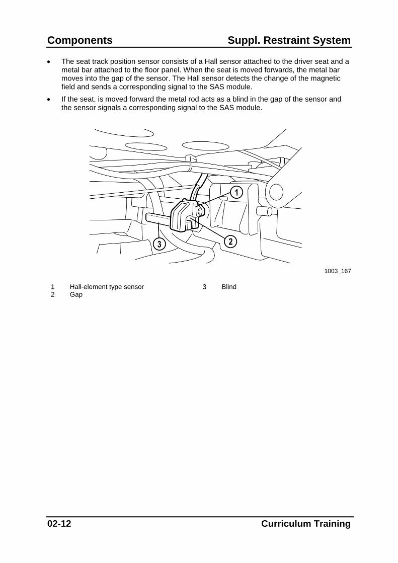
• The seat track position sensor consists of a Hall sensor attached to the driver seat and a metal bar attached to the floor panel. When the seat is moved forwards, the metal bar moves into the gap of the sensor. The Hall sensor detects the change of the magnetic field and sends a corresponding signal to the SAS module.
• If the seat, is moved forward the metal rod acts as a blind in the gap of the sensor and the sensor signals a corresponding signal to the SAS module.
1003_167
1 Hall-element type sensor 3 Blind 2 Gap
02-12 Curriculum Training
Suppl. Restraint System Components
Driver Front Airbag
• The driver front airbag is designed to slow down the driver’s speed to zero in case of an accident. Therefore, gas inflates a cushion between the driver and the steering wheel to reduce the driver’s forward movement in a controlled manner and prevent the driver from crashing onto the steering wheel.
• The cushion itself, which is made of thin nylon fabric, is folded and stored behind the center cover of the steering wheel. The cover has “tear lines” molded in its surface, allowing the airbag to easily exit through the cover when it is triggered.
• The airbag incorporates an inflator that is connected to the SAS module. If triggered, gas is generated within the inflator and inflates the airbag, to protect the driver.
• The driver airbag has a volume of about 45 liters and is inflated within 40…60 ms after a frontal collision. The noise generated by the airbag deployment is approx. 130 dB(A). However, because of the short duration of approx. 3 ms, a hearing defect is unlikely.
• Mazda uses two different types of driver front airbags:
– Single-stage airbag
– Dual-stage airbag
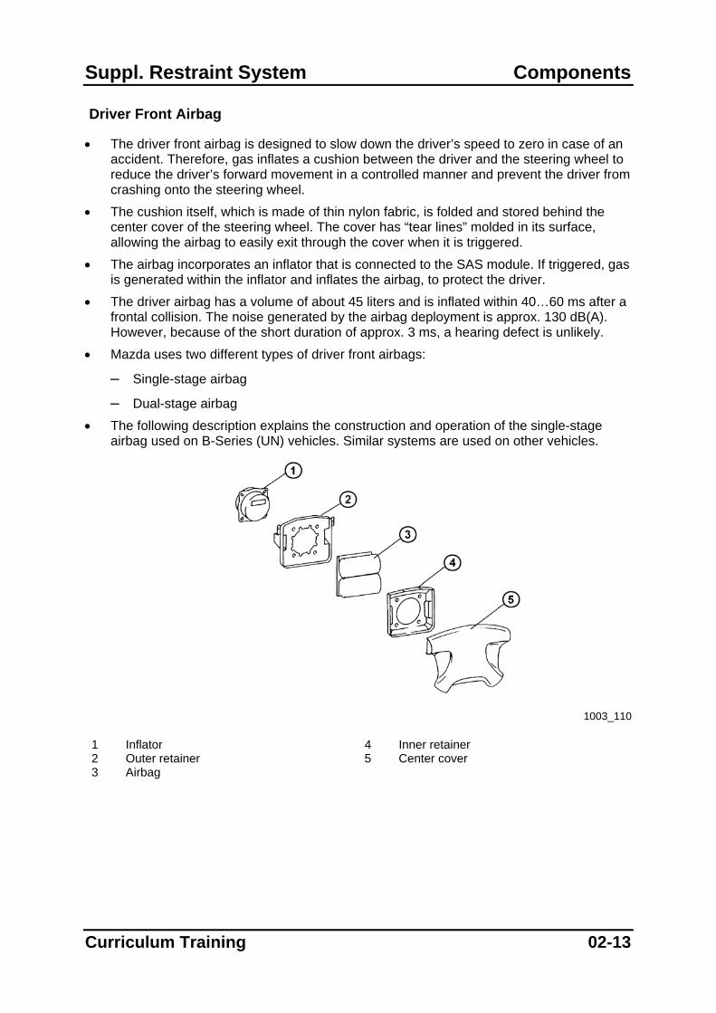
• The following description explains the construction and operation of the single-stage airbag used on B-Series (UN) vehicles. Similar systems are used on other vehicles.
1003_110
1 Inflator 4 Inner retainer 2 Outer retainer 5 Center cover 3 Airbag
Curriculum Training 02-13
Components Suppl. Restraint System
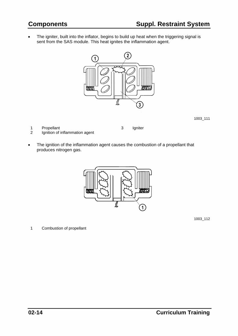
• The igniter, built into the inflator, begins to build up heat when the triggering signal is sent from the SAS module. This heat ignites the inflammation agent.
1003_111
1 Propellant 3 Igniter 2 Ignition of inflammation agent
• The ignition of the inflammation agent causes the combustion of a propellant that produces nitrogen gas.
1003_112
1 Combustion of propellant
02-14 Curriculum Training

Suppl. Restraint System Components
• The nitrogen produced in the inflator, is filtered and cooled by the filter from about 600…800° C to less than 80° C before being output to the airbag.
1003_113
1 To airbag 2 Filter
• The airbag breaks through the tear line of the airbag cover when it is inflated, with the
driver’s head contacting it when it is completely inflated. The force transmitted to the driver is reduced by allowing gas to escape through the vent hole.
1003_114
1 Vent hole • As the driver strikes the airbag it begins to deflate, and is completely deflated after less
than one second from the beginning of the accident. NOTE: The powdery substance released from the airbag during inflation is talcum powder or
a similar substance, which is used by the airbag manufacturers to keep the cushion pliable and prevent it from sticking while it is stored.
NOTE: Powdery substances, which are remaining after airbag deployment can be toxic
residues of propellant. Thererfore always follow the corresponding safety instructions.
Curriculum Training 02-15

Components Suppl. Restraint System
Dual-Stage Airbag
• The construction and operation of a dual stage airbag is similar to a conventional airbag, except for the fact that it features two inflators as described on the following pages.
• A dual-stage airbag provides the ability to customize the inflation depending on the severity of the accident. This feature reduces the risk of serious injury caused by the deploying force of the airbag in case of an accident. Therefore, the SAS module varies the timing for triggering both stages, thus varying the deployment energy of the airbag. If it is necessary that the airbag must be fully inflated, the second stage is triggered simultaneously with or immediately after the first stage. If the SAS module decides that a fully inflated airbag could cause more injury than protection it delays the triggering of the second stage.
• The deployment energy for both stages depends on the vehicle. As an example, the energy distribution on Mazda6 vehicles is 60 % for the first stage and 40 % for the second stage.
NOTE: If it is necessary to deploy only the first stage of the dual-stage airbag the second
stage is always triggered with time delay (approx. 0.1 seconds) after the first stage. This is done for safety reasons to ensure that the second stage cannot accidentally deploy during subsequent rescue work.
02-16 Curriculum Training
Suppl. Restraint System Components
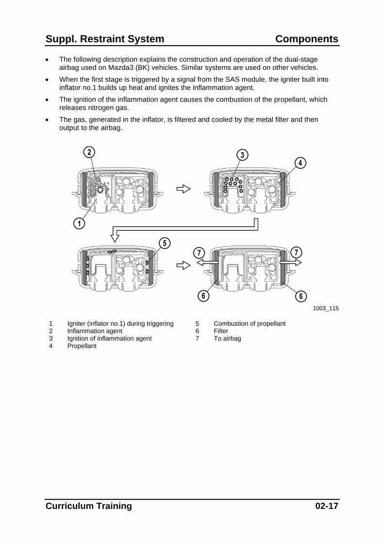
• The following description explains the construction and operation of the dual-stage airbag used on Mazda3 (BK) vehicles. Similar systems are used on other vehicles.
• When the first stage is triggered by a signal from the SAS module, the igniter built into inflator no.1 builds up heat and ignites the inflammation agent.
• The ignition of the inflammation agent causes the combustion of the propellant, which releases nitrogen gas.
• The gas, generated in the inflator, is filtered and cooled by the metal filter and then output to the airbag.
1003_115
1 Igniter (inflator no.1) during triggering 5 Combustion of propellant 2 Inflammation agent 6 Filter 3 Ignition of inflammation agent 7 To airbag 4 Propellant
Curriculum Training 02-17
Components Suppl. Restraint System
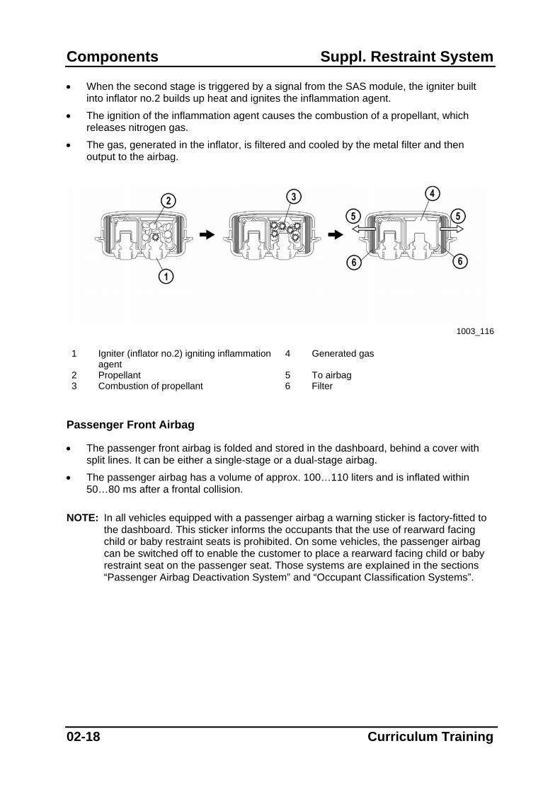
• When the second stage is triggered by a signal from the SAS module, the igniter built into inflator no.2 builds up heat and ignites the inflammation agent.
• The ignition of the inflammation agent causes the combustion of a propellant, which releases nitrogen gas.
• The gas, generated in the inflator, is filtered and cooled by the metal filter and then output to the airbag.
1003_116
1 Igniter (inflator no.2) igniting inflammation
agent 4 Generated gas
2 Propellant 5 To airbag 3 Combustion of propellant 6 Filter
Passenger Front Airbag
• The passenger front airbag is folded and stored in the dashboard, behind a cover with split lines. It can be either a single-stage or a dual-stage airbag.
• The passenger airbag has a volume of approx. 100…110 liters and is inflated within 50…80 ms after a frontal collision.
NOTE: In all vehicles equipped with a passenger airbag a warning sticker is factory-fitted to
the dashboard. This sticker informs the occupants that the use of rearward facing child or baby restraint seats is prohibited. On some vehicles, the passenger airbag can be switched off to enable the customer to place a rearward facing child or baby restraint seat on the passenger seat. Those systems are explained in the sections “Passenger Airbag Deactivation System” and “Occupant Classification Systems”.
02-18 Curriculum Training

Suppl. Restraint System Components
• Mazda uses three different types of passenger front airbags.
– One system operates similar to the single-stage driver airbag.
– One system operates similar to the dual-stage driver airbag.
– One system is inflated using highly compressed gas, which is stored in a pressure chamber.
System Using Highly Compressed Gas
• The following description explains the construction and operation of the single-stage passenger front airbag used on B-Series (UN) vehicles.
• The so called “hybrid airbags” have two advantages:
– The temperatures generated during airbag deployment are in the range below 60° C.
– The lower expansion energy acts less aggressively on the occupants.
1003_118
1 Retainer 4 Airbag 2 Inflator 5 Airbag cover 3 Mid plate
Curriculum Training 02-19
Components Suppl. Restraint System
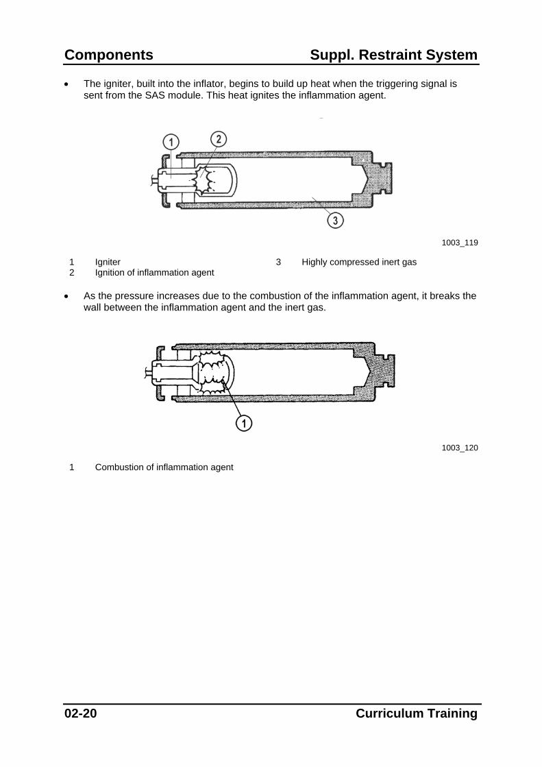
• The igniter, built into the inflator, begins to build up heat when the triggering signal is sent from the SAS module. This heat ignites the inflammation agent.
1003_119
1 Igniter 3 Highly compressed inert gas 2 Ignition of inflammation agent
• As the pressure increases due to the combustion of the inflammation agent, it breaks the
wall between the inflammation agent and the inert gas.
1003_120
1 Combustion of inflammation agent
02-20 Curriculum Training
Suppl. Restraint System Components
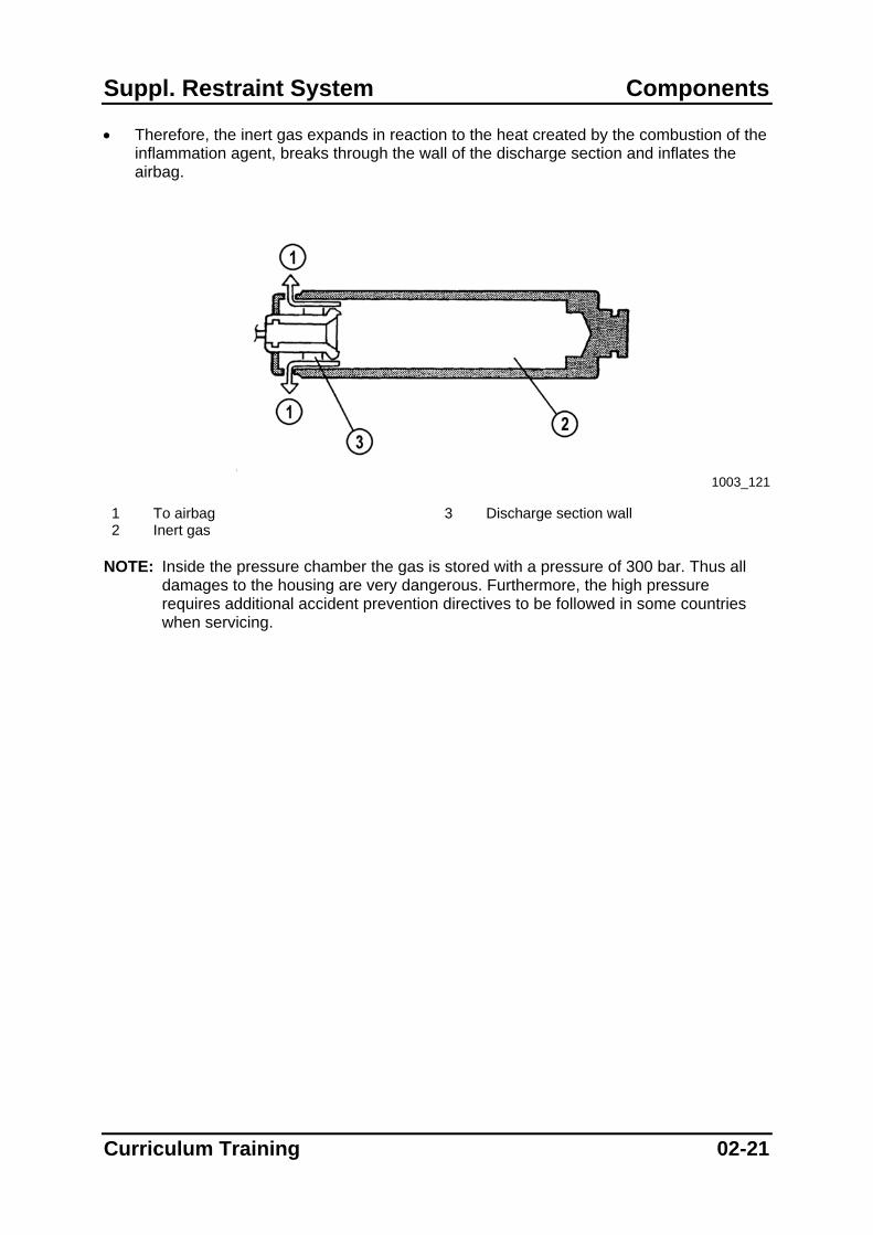
• Therefore, the inert gas expands in reaction to the heat created by the combustion of the inflammation agent, breaks through the wall of the discharge section and inflates the airbag.
1003_121
1 To airbag 3 Discharge section wall 2 Inert gas
NOTE: Inside the pressure chamber the gas is stored with a pressure of 300 bar. Thus all
damages to the housing are very dangerous. Furthermore, the high pressure requires additional accident prevention directives to be followed in some countries when servicing.
Curriculum Training 02-21
Components Suppl. Restraint System
Side Airbag
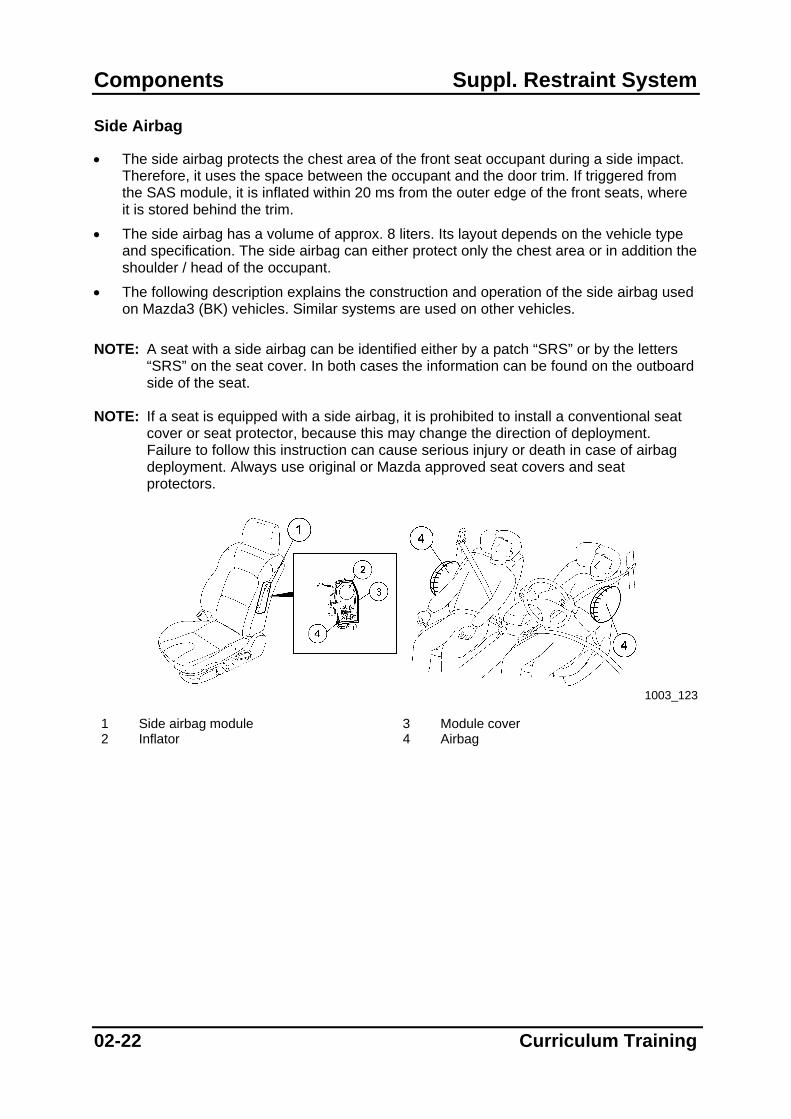
• The side airbag protects the chest area of the front seat occupant during a side impact. Therefore, it uses the space between the occupant and the door trim. If triggered from the SAS module, it is inflated within 20 ms from the outer edge of the front seats, where it is stored behind the trim.
• The side airbag has a volume of approx. 8 liters. Its layout depends on the vehicle type and specification. The side airbag can either protect only the chest area or in addition the shoulder / head of the occupant.
• The following description explains the construction and operation of the side airbag used on Mazda3 (BK) vehicles. Similar systems are used on other vehicles.
NOTE: A seat with a side airbag can be identified either by a patch “SRS” or by the letters
“SRS” on the seat cover. In both cases the information can be found on the outboard side of the seat.
NOTE: If a seat is equipped with a side airbag, it is prohibited to install a conventional seat
cover or seat protector, because this may change the direction of deployment. Failure to follow this instruction can cause serious injury or death in case of airbag deployment. Always use original or Mazda approved seat covers and seat protectors.
1003_123
1 Side airbag module 3 Module cover 2 Inflator 4 Airbag
02-22 Curriculum Training

Suppl. Restraint System Components
• The igniter, build into the inflator, begins to build up heat when the triggering signal is sent from the SAS module. This ignites the inflammation agent, causing the combustion of the propellant that releases nitrogen gas.
• As the pressure increases, it shifts the nail into the break washer, thus the L-steel lock is released and the L-steel moves destroying the break washer with the aid of the nail. As a result, the inert gas out of the pressure chamber is mixed with combustion gas and inflates the side airbag via the inner tube.
• The side airbag begins to deflate about 100 ms after being inflated.
1003_124
1 Igniter 6 L-Steel 2 Combustion of inflammation agent 7 Nail 3 Break washer 8 Inert gas 4 Pressure chamber 9 To airbag 5 Propellant 10 Inner tube
NOTE: Inside the pressure chamber the gas is stored with a pressure of 300 bar. Thus all
damages to the housing are very dangerous. Furthermore, the high pressure requires additional accident prevention directives to be followed in some countries when servicing.
Curriculum Training 02-23

Components Suppl. Restraint System
Curtain Airbag
• The curtain airbag increases the head and shoulder protection of the front and rear seat occupants in the event of a side impact. Therefore, it uses the space between the occupants and the doors. If triggered from the SAS module, it is inflated along the roof between the A and C pillars, where it is stored behind the trim.
• The curtain airbag has a volume of approx. 12…19 liters and inflates within 15…30 ms after a side collision. It stays inflated for up to a few minutes, in order to protect the occupants even in case of a lateral rollover.
• The following description explains the construction and operation of the curtain airbag used on Mazda3 (BK) vehicles. Similar systems are used on other vehicles.
NOTE: A vehicle with curtain airbags can be identified by the letters “SRS” on the trim of the
A and C pillar.
1003_125
1 Inflator 3 Airbag cover 2 Curtain airbag 4 Airbag
02-24 Curriculum Training

Suppl. Restraint System Components
• When the curtain airbag is triggered by a signal from the SAS module, the igniter builds up heat and ignites the inflammation agent. Thus combustion gas is generated and the increased pressure breaks the sealing disc.
• The inert gas out of the pressure chamber expands and destroys the burst disc inflating the airbag via the diffusor orifice. Thus the trims spread apart and the airbag is inflated between the head and shoulder area of the outboard occupants and the doors.
1003_126
1 Igniter 6 Diffusor 2 Inflammation agent 7 Combustion of inflammation agent 3 Sealing disc 8 Inert gas expansion 4 Combined gas 9 To airbag 5 Burst disc
NOTE: Inside the pressure chamber the gas is stored with a pressure of 300 bar. Thus all
damages to the housing are very dangerous. Furthermore, the high pressure requires additional accident prevention directives to be followed in some countries when servicing.
Curriculum Training 02-25
Components Suppl. Restraint System
Connectors in Trigger Circuit
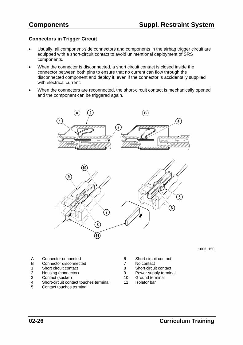
• Usually, all component-side connectors and components in the airbag trigger circuit are equipped with a short-circuit contact to avoid unintentional deployment of SRS components.
• When the connector is disconnected, a short circuit contact is closed inside the connector between both pins to ensure that no current can flow through the disconnected component and deploy it, even if the connector is accidentally supplied with electrical current.
• When the connectors are reconnected, the short-circuit contact is mechanically opened and the component can be triggered again.
1003_150
A Connector connected 6 Short circuit contact B Connector disconnected 7 No contact 1 Short circuit contact 8 Short circuit contact 2 Housing (connector) 9 Power supply terminal 3 Contact (socket) 10 Ground terminal 4 Short-circuit contact touches terminal 11 Isolator bar 5 Contact touches terminal
02-26 Curriculum Training
Suppl. Restraint System Components
Seatbelt
• The whole SRS is not able to protect an occupant if he does not properly wear the seatbelt. Most seats are equipped with three-point seatbelts, which hold the occupant in his seat and reduces uncontrolled movement of the occupant’s body in case of an accident.
• The seatbelts that are used on Mazda vehicles feature an Emergency Locking Retractor function. In addition they can be equipped with an Automatic Locking Retractor, a belt pretensioner and a belt load limiter.
NOTE: The seatbelts have to be inspected after each accident. Depending on the vehicle
type, they have to be replaced even when the pretensioners are not triggered and there is no wear. Therefore, always refer to the W/M when inspecting the seatbelts.
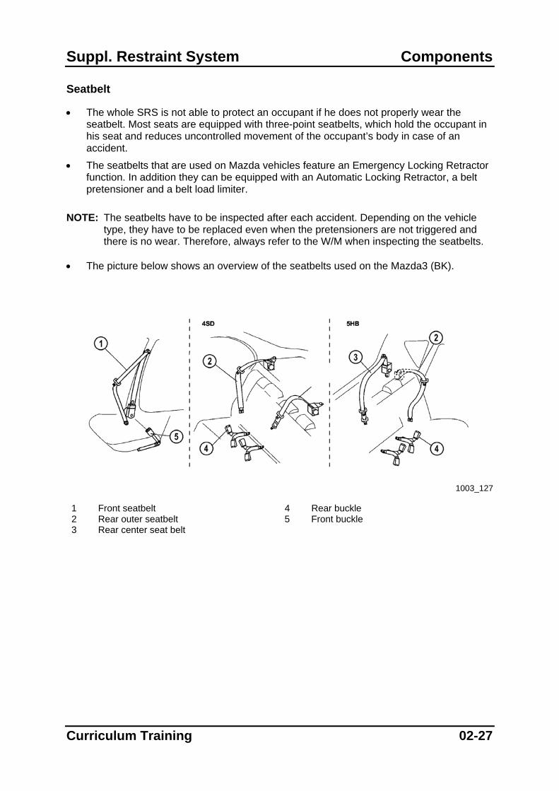
• The picture below shows an overview of the seatbelts used on the Mazda3 (BK).
1003_127
1 Front seatbelt 4 Rear buckle 2 Rear outer seatbelt 5 Front buckle 3 Rear center seat belt
Curriculum Training 02-27

Components Suppl. Restraint System
• The picture below shows the construction of a belt retractor used on the Mazad3 (BK)
1003_169
1 Spring cover 12 Tie Bar 2 Retractor spring 13 Adapter 3 Spring plate 14 Lever C 4 Housing 15 Lever A 5 Webbing guide 16 Steering disc 6 Lever B 17 Steering disc spring 7 Weight 18 Bushing 8 Bearing 19 Steering head 9 Wobble gear 20 Ring 10 Cover 21 Torsion bar 11 Pawl 22 Guide drum
02-28 Curriculum Training
Suppl. Restraint System Components
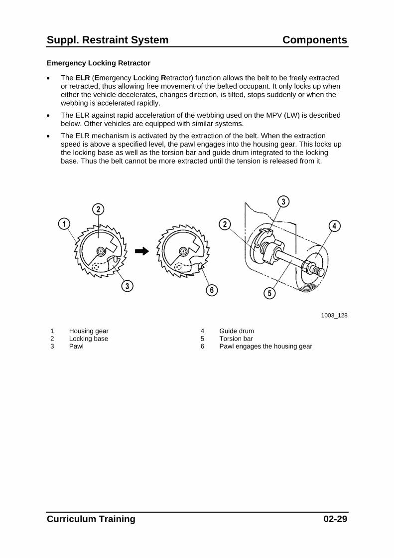
Emergency Locking Retractor
• The ELR (Emergency Locking Retractor) function allows the belt to be freely extracted or retracted, thus allowing free movement of the belted occupant. It only locks up when either the vehicle decelerates, changes direction, is tilted, stops suddenly or when the webbing is accelerated rapidly.
• The ELR against rapid acceleration of the webbing used on the MPV (LW) is described below. Other vehicles are equipped with similar systems.
• The ELR mechanism is activated by the extraction of the belt. When the extraction speed is above a specified level, the pawl engages into the housing gear. This locks up the locking base as well as the torsion bar and guide drum integrated to the locking base. Thus the belt cannot be more extracted until the tension is released from it.
1003_128
1 Housing gear 4 Guide drum 2 Locking base 5 Torsion bar 3 Pawl 6 Pawl engages the housing gear
Curriculum Training 02-29

Components Suppl. Restraint System
• The ELR mechanism locking in case of deceleration, changes of direction, tilted vehicle and sudden stop is described below. The pictures serve only as an example.
• The ELR consists of a ball, a lever and a lock gear attached to the guide drum.
• The ball is free to move. When the vehicle is not on level ground or a sudden shock is applied to the vehicle, the ball moves to push the lever upward, so that it engages with the lock gear and stops the rotation of the guide drum.
• The guide drum will be unlocked when the ball is moved back to its initial position and no tension is applied to the seatbelt.
1003_173 1 Lock gear attached to the guide drum 4 ELR release function not operated 2 Actuator 5 ELR release function operated 3 Ball
02-30 Curriculum Training

Suppl. Restraint System Components
ELR Release Function
• The RX-8 (SE) features an ELR release function. This is necessary due to the fact that on the RX-8 the seatbelt retractors for the front seatbelts are installed in the rear doors. In order to open the rear doors completely, the seat belt webbing has to unwind from the guide drum even when the vehicle is tilted.
• The ELR release function is controlled by the RKE (Remote Keyless Entry) module and only inhibits the locking of the guide drum due to a tilted position of the vehicle. The seatbelt will always lock when the webbing is quickly unwound from the reel.
• The picture below shows an overview of the components.
1003_168
1 Remote Keyless Entry module 6 Ball 2 Rear door upper latch switch 7 Front door switch (in rear door) 3 Actuator 8 Rear door lower latch switch 4 Lock release solenoid 9 Front seatbelt retractor 5 Cancel lever 10 Front buckle switch
Curriculum Training 02-31

Components Suppl. Restraint System
• The wiring diagram below shows the condition with all doors open and seat belts not buckled. The lock release solenoids are actuated in this condition by current flowing from the RKE module via the respective switches to ground.
1003_175
1 Keyless unit 7 Rear door lower latch switch (left side) 2 Front buckle switch (right side) 8 Rear door upper latch switch (left side) 3 Lock release solenoid (right side) 9 Front door switch (left side) 4 Rear door lower latch switch (right side) 10 Instrument cluster 5 Rear door upper latch switch (right side) 11 Front buckle switch (left side) 6 Front door switch (right side) 12 Lock release solenoid (left side)
02-32 Curriculum Training

Suppl. Restraint System Components
• When the ELR release function is not operated (normal condition, e.g. when driving), the ball lock release solenoid is not activated, thus the ball is free to move. When the vehicle is not on level ground or a sudden shock is applied to the vehicle, the ball moves to push the actuator upward so that it engages with the lock gear and stops the rotation of the guide drum.
• When a rear door is opened and the corresponding front seatbelt is not buckled, the respective lock release solenoid is actuated from the RKE module via the switches and pushes the cancel lever upward. As a result, the actuator and ball are fixed in their positions. Due to this, the front seat belt unwinds smoothly when the rear door is opened.
• The ELR release function does not operate under the following conditions:
– When the coresponding rear door is closed.
– When the corresponding front seatbelt is buckled.
– When one hour has elapsed with a door open (battery saver function).
– When the battery is disconnected or the ROOM fuse is removed.
1003_174
1 Lock release solenoid 5 Cancel lever 2 Lock gear 6 ELR release function not operated 3 Actuator 7 ELR release function operated 4 Ball 8 Actuator fulcrum
Curriculum Training 02-33

Components Suppl. Restraint System
Automatic Locking Retractor
• The ALR (Automatic Locking Retractor) function enables the customer to fix a child-restraint seat securely onto a seat. The seatbelt retractor automatically locks and remains locked when it is buckled, and does not allow any freedom of movement.
• To enable the ALR function, the seatbelt has to be pulled out completely. A ratcheting noise can be heard when the belt is pulled then back onto the guide drum. Then the belt length can only be decreased but not increased. The ALR function is disabled automatically when the seatbelt is pulled back onto the guide drum completely.
NOTE: Depending on the vehicle, all seats except for the driver seat can be equipped with
this special feature. Most seatbelts with ALR function can be identified by a special patch as shown below.
1003_129
Sample patch for ALR
02-34 Curriculum Training
Suppl. Restraint System Components
Belt Pretensioner
• Most front seatbelts are equipped with a belt pretensioner system that serves to remove excess slack from the seatbelt in case of an accident. Mazda uses pyrotechnic belt pretensioners.
• If triggered from the SAS module, the belt pretensioner needs approx. 15 ms to remove up to approx. 6…12 cm slack from the seatbelt.
NOTE: If the belt pretensioners are triggered, the seatbelts have to be replaced as a unit. If
the belt pretensioner is not integrated in the retractor, it has to be replaced in addition to the seatbelt.
NOTE: If the front airbags are triggered, the belt pretensioners are triggered as well. • Mazda uses four different types of belt pretensioners:
– Rack-operated belt pretensioner
– Ball-operated belt pretensioner
– Rotor-operated belt pretensioner
– Cable-operated belt pretensioner
• The different types of the belt pretensioners that are explained on the following pages serve only as an example. The layout of the systems can vary but the construction and operation is similar to those that are explained.
Curriculum Training 02-35
Components Suppl. Restraint System
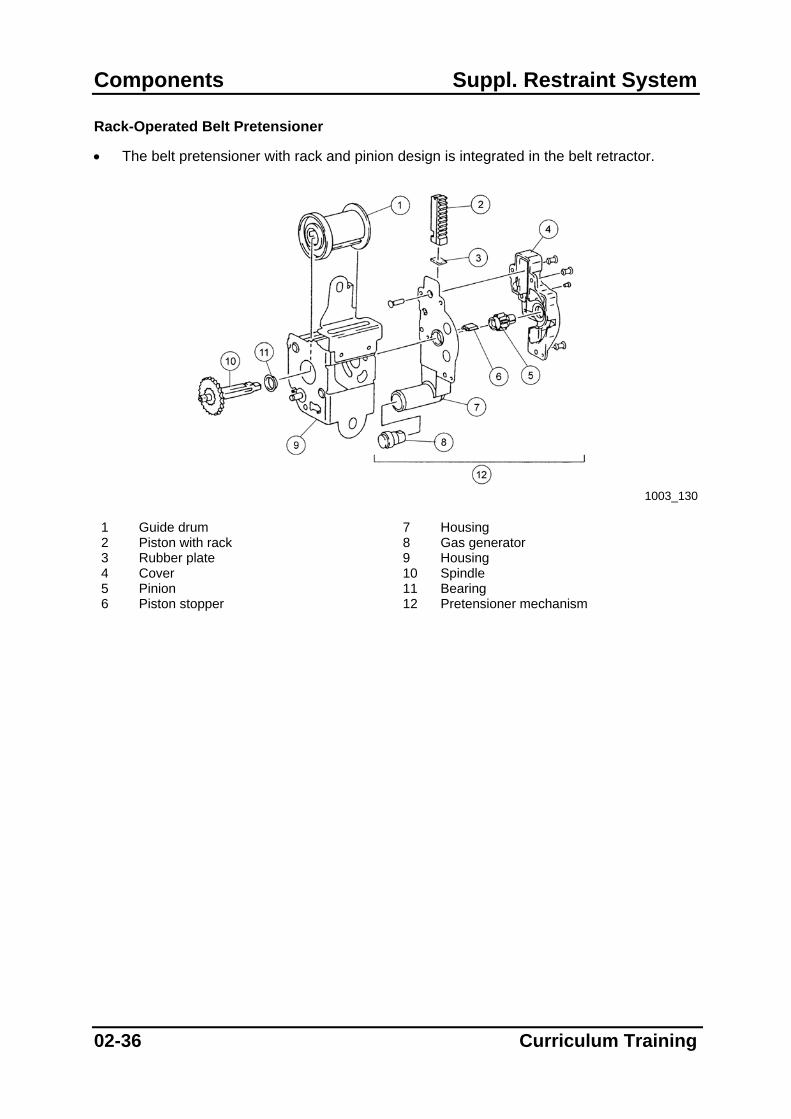
Rack-Operated Belt Pretensioner
• The belt pretensioner with rack and pinion design is integrated in the belt retractor.
1003_130
1 Guide drum 7 Housing 2 Piston with rack 8 Gas generator 3 Rubber plate 9 Housing 4 Cover 10 Spindle 5 Pinion 11 Bearing 6 Piston stopper 12 Pretensioner mechanism
02-36 Curriculum Training

Suppl. Restraint System Components
• The piston is usually fixed by the piston stopper, and is therefore completely separated from the movement of the pinion. The pinion is connected to the spindle running through the center of the guide drum and rotates freely according to the movement of the belt.
1003_131
1 Belt 4 Piston with rack 2 Pinion 5 Spindle 3 Piston stopper 6 Guide drum
Curriculum Training 02-37

Components Suppl. Restraint System
• When the pretensioner is triggered by a signal from the SAS module, the gas generator produces combustion gas.
• As the pressure in the housing increases due to the expanding gas, the piston is pushed up, shears off the piston stopper, engages the gear and causes the pinion to rotate. As a result, the spindle rotates the guide drum and retracts the seatbelt.
1003_132
1 Belt 5 Spindle 2 Piston stopper 6 Gas pressure 3 Piston with rack 7 Housing 4 Pinion 8 Guide drum
02-38 Curriculum Training

Suppl. Restraint System Components
Ball-Operated Belt Pretensioner
• The ball-operated belt pretensioner is integrated in the belt retractor.
1003_133 1 Spring unit 12 Fly wheel 2 Pinion 13 Sensor unit 3 Guide drum 14 Pretensioner plate 4 Torsion bar 15 Ring gear 5 Pawl 16 Stopper spring 6 Pawl spring 17 Balls 7 Locking base 18 Gas generator 8 Housing 19 Guide block 9 Lock gear 20 Pipe 10 Hook spring 21 Pretensioner cover 11 Retainer 22 Guide plate
Curriculum Training 02-39

Components Suppl. Restraint System
• The guide drum has a pinion on its end, which rotates with the guide drum according to the movement of the belt. The ring gear does not engage with the pinion during normal operation, thus it does not rotate even when the belt is retracted or withdrawn.
1003_134
1 Ring gear 3 Pinion 2 Guide drum
• If the belt pretensioner is triggered by a signal from the SAS module, the gas generator
produces combustion gas.
• The balls are forced up in the pipe as the pressure in the housing increases due to the expanding gas. The balls movement engages the ring gear with the pinion and transfers rotational movement via the torsion bar to the guide drum. Thus the guide drum rotates and retracts the seatbelt.
1003_135
1 Pinion 4 Gas pressure 2 Ring gear 5 Gas generator 3 Ball
02-40 Curriculum Training
Suppl. Restraint System Components
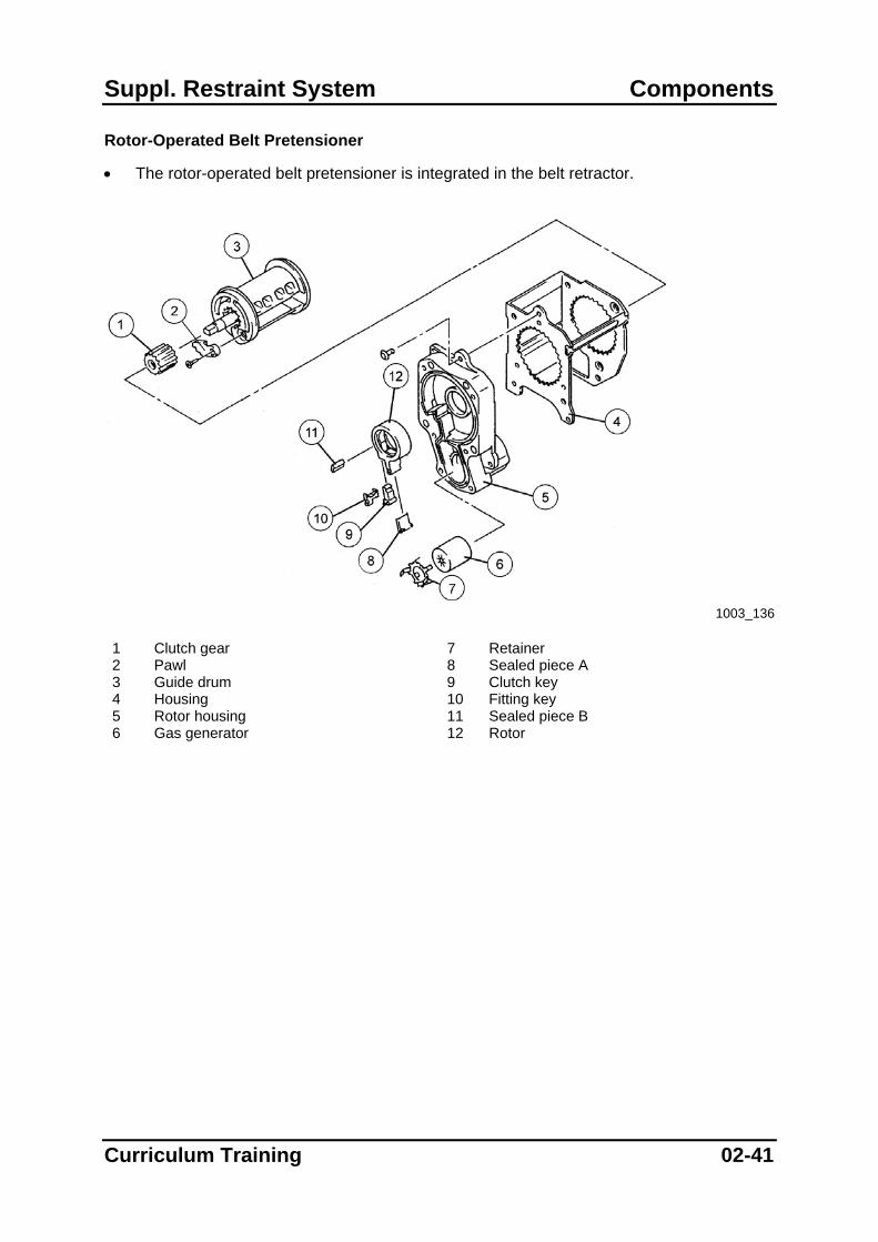
Rotor-Operated Belt Pretensioner
• The rotor-operated belt pretensioner is integrated in the belt retractor.
1003_136
1 Clutch gear 7 Retainer 2 Pawl 8 Sealed piece A 3 Guide drum 9 Clutch key 4 Housing 10 Fitting key 5 Rotor housing 11 Sealed piece B 6 Gas generator 12 Rotor
Curriculum Training 02-41

Components Suppl. Restraint System
• The guide drum has a clutch gear on its end, which rotates with the guide drum according to the movement of the belt. The rotor around the gear is not engaged with the gear during normal operation, thus it does not rotate even when the belt is retracted or withdrawn.
1003_137
1 Clutch gear 4 Clutch key 2 Guide drum 5 Gas generator 3 Rotor
• When the pretensioner is triggered by a signal from the SAS module, the gas generator
generates combustion gas.
• The expanding gas increases the pressure in the housing, pushes up the clutch key and engages the rotor and clutch gear. As a result, the rotor rotates together with the guide drum and retracts the seatbelt.
1003_138
1 Rotor 4 Gas generator 2 Clutch key 5 Gas pressure 3 Clutch gear
02-42 Curriculum Training
Suppl. Restraint System Components
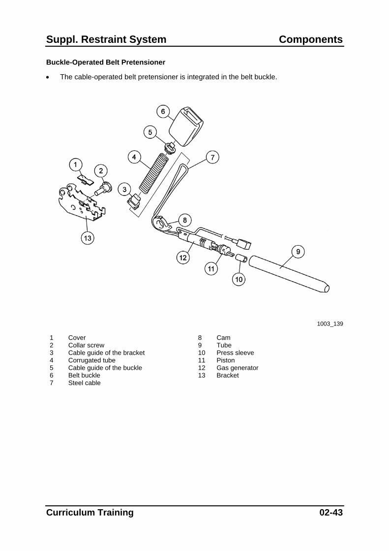
Buckle-Operated Belt Pretensioner
• The cable-operated belt pretensioner is integrated in the belt buckle.
1003_139
1 Cover 8 Cam 2 Collar screw 9 Tube 3 Cable guide of the bracket 10 Press sleeve 4 Corrugated tube 11 Piston 5 Cable guide of the buckle 12 Gas generator 6 Belt buckle 13 Bracket 7 Steel cable
Curriculum Training 02-43
Components Suppl. Restraint System
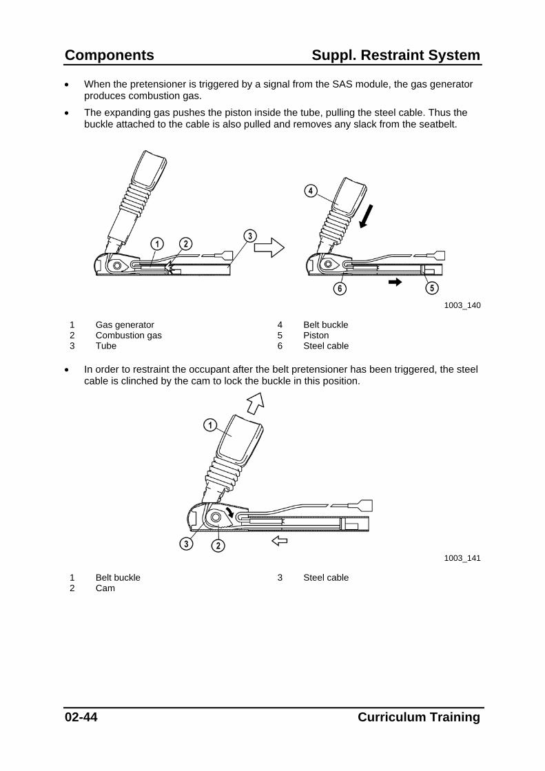
• When the pretensioner is triggered by a signal from the SAS module, the gas generator produces combustion gas.
• The expanding gas pushes the piston inside the tube, pulling the steel cable. Thus the buckle attached to the cable is also pulled and removes any slack from the seatbelt.
1003_140
1 Gas generator 4 Belt buckle 2 Combustion gas 5 Piston 3 Tube 6 Steel cable
• In order to restraint the occupant after the belt pretensioner has been triggered, the steel
cable is clinched by the cam to lock the buckle in this position.
1003_141
1 Belt buckle 3 Steel cable 2 Cam
02-44 Curriculum Training

Suppl. Restraint System Components
Belt Force Limiter
• Seatbelts that feature a belt pretensioner are usually equipped with a belt force limiter mechanism in order to reduce the risk of chest injuries in case of an accident.
• The belt force limiter is integrated in the belt retractor and consists of a torsion bar, which connects the guide drum to the locking base.
• When the locking base is locked (due to the operation of the ELR) and a significant force that could cause further injury to the chest area is applied to the belt, the torsion bar twists and absorbs the overload against the chest.
NOTE: The seatbelt has to be replaced after activation of the belt pretensioner (even in case
of a buckle-operated type) or after operation of the belt force limiter.
1003_142
1 Belt 3 Torsion bar 2 Guide drum 4 Locking base
Curriculum Training 02-45
Components Suppl. Restraint System
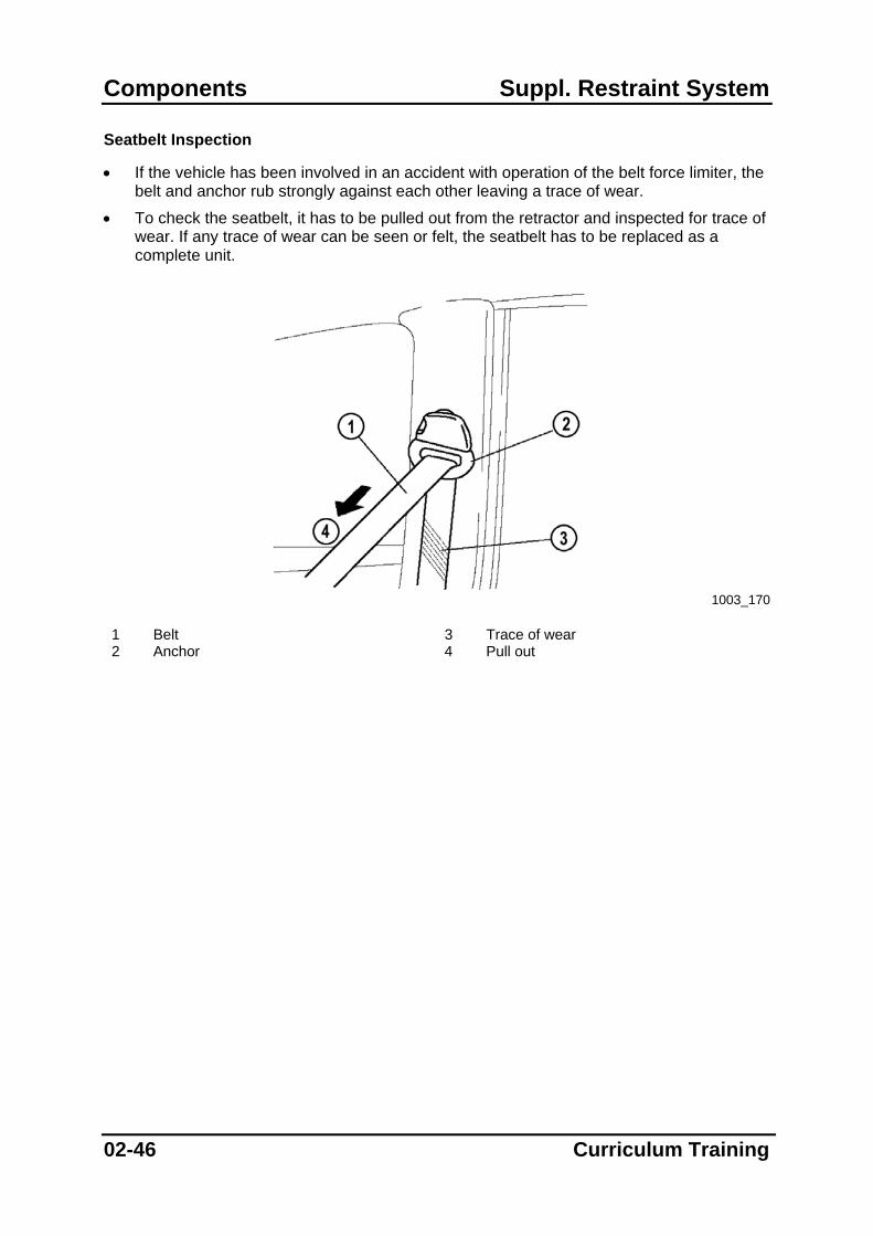
Seatbelt Inspection
• If the vehicle has been involved in an accident with operation of the belt force limiter, the belt and anchor rub strongly against each other leaving a trace of wear.
• To check the seatbelt, it has to be pulled out from the retractor and inspected for trace of wear. If any trace of wear can be seen or felt, the seatbelt has to be replaced as a complete unit.
1003_170
1 Belt 3 Trace of wear 2 Anchor 4 Pull out
02-46 Curriculum Training
Suppl. Restraint System Components
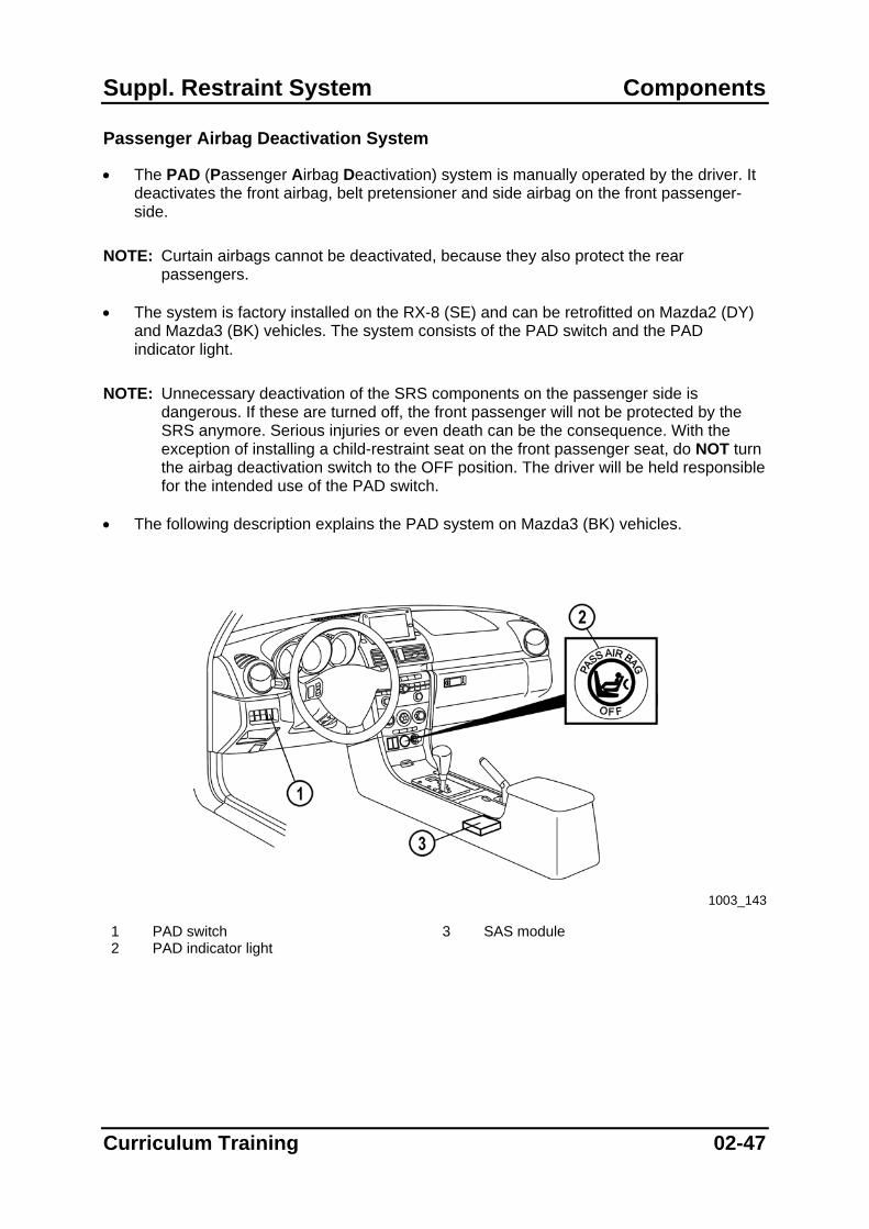
Passenger Airbag Deactivation System
• The PAD (Passenger Airbag Deactivation) system is manually operated by the driver. It deactivates the front airbag, belt pretensioner and side airbag on the front passenger-side.
NOTE: Curtain airbags cannot be deactivated, because they also protect the rear
passengers. • The system is factory installed on the RX-8 (SE) and can be retrofitted on Mazda2 (DY)
and Mazda3 (BK) vehicles. The system consists of the PAD switch and the PAD indicator light.
NOTE: Unnecessary deactivation of the SRS components on the passenger side is
dangerous. If these are turned off, the front passenger will not be protected by the SRS anymore. Serious injuries or even death can be the consequence. With the exception of installing a child-restraint seat on the front passenger seat, do NOT turn the airbag deactivation switch to the OFF position. The driver will be held responsible for the intended use of the PAD switch.
• The following description explains the PAD system on Mazda3 (BK) vehicles.
1003_143
1 PAD switch 3 SAS module 2 PAD indicator light
Curriculum Training 02-47
Components Suppl. Restraint System
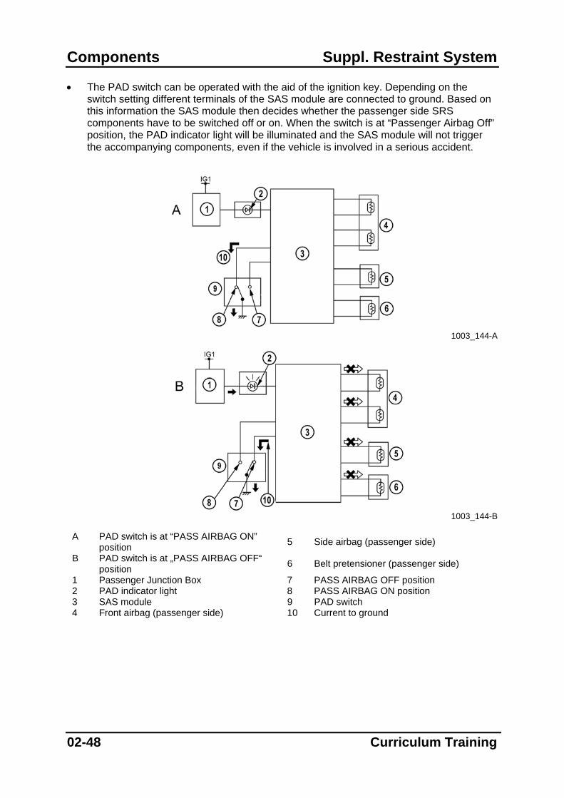
• The PAD switch can be operated with the aid of the ignition key. Depending on the switch setting different terminals of the SAS module are connected to ground. Based on this information the SAS module then decides whether the passenger side SRS components have to be switched off or on. When the switch is at “Passenger Airbag Off” position, the PAD indicator light will be illuminated and the SAS module will not trigger the accompanying components, even if the vehicle is involved in a serious accident.
1003_144-A
1003_144-B
A PAD switch is at “PASS AIRBAG ON”
position 5 Side airbag (passenger side)
B PAD switch is at „PASS AIRBAG OFF“ position 6 Belt pretensioner (passenger side)
1 Passenger Junction Box 7 PASS AIRBAG OFF position 2 PAD indicator light 8 PASS AIRBAG ON position 3 SAS module 9 PAD switch 4 Front airbag (passenger side) 10 Current to ground
02-48 Curriculum Training

Suppl. Restraint System Components
PAD Retrofitting
• If a customer wants to have a PAD switch installed, it is possible to retrofit the switch. The necessary parts can be ordered for the Mazda2 (as a kit) and for the Mazda3 (separate components).
NOTE: Always observe your national legal requirements when retrofitting a PAD switch. • When retrofitting a PAD switch on the Mazda2 work according to SI (Service
Information) L004/03.
– Install the PAD switch
– Install the PAD indicator light
– Install the wiring harness (only Mazda2)
– Perform the SAS module configuration using WDS
– Explain the operation of the PAD system to the customer.
– Have the customer sign a declaration that he agrees to the installation of the PAD switch and that the operation of the PAD system has been fully explained.
– Hand over one copy of the declaration to the customer and deposit the original copy in a safe place.
NOTE: According to EU consumer protection legislation the dealership must retain the
signed declaration for 10 years. NOTE: After installation of a PAD switch the relevant information should be added to the
service log of the vehicle.
Curriculum Training 02-49

Components Suppl. Restraint System
Occupant Classification Systems
Passenger Occupancy Detection System
• The PODS (Passenger Occupancy Detection System) is automatically controlled by the SAS module. It deactivates the front airbag, belt pretensioner and side airbag on the front passenger-side, when the seat is occupied with a load below a specified limit (approx. 12 kg) or with a special Mazda child restraint seat with integrated transponder.
NOTE: Curtain airbags cannot be deactivated, because they also protect the rear
passengers. • The system consists of sensor mat with control module (incorporated into the seat
cushion) and the PAD indicator light.
1003_145
1 SAS module 3 Occupancy sensor 2 PAD indicator light
02-50 Curriculum Training

Suppl. Restraint System Components
• The sensor mat incorporates a large number of pressure sensitive resistors. These are connected to the control module, which processes the individual signals and transfers them to the SAS module. Furthermore one transmitting and two receiving antennas are also incorporated into the sensor mat and connected to the sensor module.
NOTE: The sensor mat can only be replaced as a unit together with the seat cushion. • The control module detects the load on the seat via the resistance of the sensor mat and
sends a corresponding signal to the SAS module.
• When the passenger seat is either not occupied or the load is below the specified limit, the SAS module uses this information to deactivate the passenger airbag, belt pretensioner and side airbag. Thus they will not be triggered even in case of a serious accident.
1003_171
1 Occupancy sensor 5 Seat not occupied, high resistance 2 One sending antenna 6 Seat occupied, low resistance 3 Two receiving antennas 7 Resistance mat 4 Sensor module
• Furthermore, the occupancy sensor is able to detect a child restraint seat with
transponders. Therefore, it generates an electric field using the sending antenna. In case a Mazda child restraint seat with integrated transponders is used, the transponders are excited by the electric field so that they impose a code on the sending field by means of modulation. This electric field is detected via the two receiving antennas and evaluated by the control module.
Curriculum Training 02-51

Components Suppl. Restraint System
• As a result, the control module sends a corresponding signal to the SAS module to inform it about the installation of a child restraint seat. Because of that, the SAS module will activate the PAD indicator light and will not trigger the accompanying components even if the vehicle is involved in a serious accident.
• The child restraint seat will be detected by the PODS within a maximum of 40 seconds after it has been installed.
NOTE: Metal parts or magnetic cards must not be positioned on the seat, as they might
cause unintentional activation/deactivation of the passenger airbag system, resulting in serious injury or death in case of an accident.
1003_146
1 Transponder
1003_172
1 Plastic housing 3 Wire wound coil 2 Coil carrier 4 Integrated circuit
02-52 Curriculum Training

Suppl. Restraint System Components
• The table below gives an overview of the PODS functionality.
No load Low load High load Condition Item
Child restraint seat without
transponder on passenger front
seat
Child restraint seat with
transponder on passenger front
seat
Child restraint seat without
transponder on passenger front
seat
Child restraint seat with
transponder on passenger front
seat Passenger front
airbag, side airbag and belt
pretensioner will not be triggered
X X X X
Passenger front airbag, side
airbag and belt pretensioner will
be triggered if necessary
X
PAD indicator light illuminated X X
Occupant Classification System Used on Mazda Tribute Facelift
• The PODS of the Mazda Tribute Facelift consists of a seat weight sensor, seat weight sensor control module, belt tension sensor and a PAD light. The system provides information regarding the passenger’s weight and the belt tension to the SAS module, which can have an influence on the triggering strategy of the passenger airbag.
NOTE: It is prohibited to use a child restraint seat on the passenger front seat (refer to the
owners manual).
Curriculum Training 02-53

Components Suppl. Restraint System
• The seat weight sensor incorporates a silicone-filled cushion, which is connected to the sensor via a hose. The silicon varies the pressure acting on the seat weight sensor according to the load on the seat. Thus the sensor is able to send a load signal to the seat weight sensor control module, from where it is transmitted via a separate HS-CAN (High Speed – Controller Area Network) bus to the SAS module. The module can then use this information to influence the triggering strategy of the passenger airbag.
NOTE: The seat weight sensor and the seat weight sensor control module are calibrated to
each other and may only be replaced as a unit. NOTE: The seat weight sensor must be reset with the aid of the WDS after it has been
replaced or the seat trim/cushion has been removed. Therefore, connect the WDS and select “Toolbox Body Restraints Seat Weight Sensor ReZero” to reset the seat weight sensor.
1003_147
1 Silicon filled cushion 3 Seat weight sensor control module 2 Seat weight sensor 4 Underlay for silicone-filled cushion
02-54 Curriculum Training

Suppl. Restraint System Components
• The system also features a belt tension sensor, which is integrated in the lower belt anchor point. It detects the belt tension and sends an equivalent signal via the seat weight sensor control module to the SAS module. When a load is properly belted using the ALR function a “belt tension high” signal is transmitted to the SAS control module.
1003_148
• The SAS module uses the signals from the seat weight sensor and the belt tension
sensor to determine whether and whereby the front passenger seat is occupied. The table below is an overview of the PODS functionality.
No load Low load Between low and high load High load Condition Item
Buckled without ALR function /
belt is not tensioned
Buckled with ALR function /
belt is tensioned Passenger front airbag and belt
pretensioner will not be triggered
X X X
Passenger front airbag and belt
pretensioner will be triggered if
necessary
X X
PAD indicator light illuminated X X
Curriculum Training 02-55
Components Suppl. Restraint System
Mazda Vehicles and their SRS Components
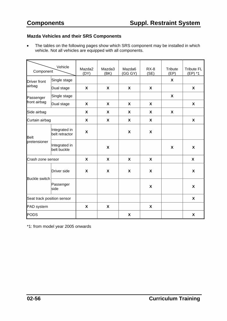
• The tables on the following pages show which SRS component may be installed in which vehicle. Not all vehicles are equipped with all components.
Vehicle Component Mazda2
(DY) Mazda3
(BK) Mazda6 (GG GY)
RX-8 (SE)
Tribute (EP)
Tribute FL (EP) *1
Single stage X Driver front airbag Dual stage X X X X X
Single stage X Passenger front airbag Dual stage X X X X X
Side airbag X X X X X
Curtain airbag X X X X X
Integrated in belt retractor X X X
Belt pretensioner
Integrated in belt buckle X X X
Crash zone sensor X X X X X
Driver side X X X X X
Buckle switch Passenger side X X
Seat track position sensor X
PAD system X X X
PODS X X
*1: from model year 2005 onwards
02-56 Curriculum Training

Suppl. Restraint System Components
Vehicle Component MPV FL1
(LW) *1 MPV FL2 (LW) *2
Premacy (CP)
MX-5 (NB)
MX-5 FL (NB) *3
B-Series (UN)
Single stage X X X X X X Driver front airbag Dual stage
Single stage X X X X X X Passenger front airbag Dual stage
Side airbag X X X
Curtain airbag
Integrated in belt retractor X X X X X
Belt pretensioner
Integrated in belt buckle
Crash zone sensor X
Driver side
Buckle switch Passenger side
Seat track position sensor
PAD system
PODS X X X X
*1: above VIN (Vehicle Identification Number) 200.000 *2: above VIN 300.000 *3: above VIN 200.000
Curriculum Training 02-57

Components Suppl. Restraint System
Notes:
02-58 Curriculum Training

Suppl. Restraint System Operation
Operation
• The operation of the SRS is described on the following pages. All explanations are based on the Mazda3. Other vehicles are equipped with similar systems.
Parts Location
1003_151
1 Crash zone sensor 7 Passenger front airbag 2 SRS warning light 8 SAS module 3 PAD switch 9 Pretensioner front buckle 4 Clock spring 10 Side airbag sensor 5 Driver front airbag 11 Side airbag 6 PAD indicator 12 Curtain airbag
Curriculum Training 03-1

Operation Suppl. Restraint System
03-2 Curriculum Training
Frontal Collision
• If a vehicle is involved in such a serious frontal collision, that the measured values of the accelerometers exceed the triggering threshold of the SAS module, the relevant SRS components will be triggered by a signal from the module.
• The pretensioners and the first stage of the front airbags are triggered simultaneously. The pretensioner reaches full effectiveness within the first 20 ms following the impact, and serves as a supplement to the airbag, which will be fully inflated after about 50 ms.
• The deployment energy is controlled by the SAS module. Therefore, it varies the time delay for triggering the second stage, depending on the input signals and stored map values.
• If the SAS module decides that the best occupant protection is achieved when triggering only the first stage, the second stage is nonetheless triggered for safety reasons with a delay of approximately 100 ms, thus the rescue personnel is not endangered by an untriggered inflator.
• The picture on the next page shows a possible sequence of the SRS operation during a frontal collision. All values stated serve purely as an example.

Suppl. Restraint System Operation
1003_152
1 Driver 5 Airbags and pretensioners triggered,
seatbelt pretensioned 2 Time in milliseconds 6 Airbag inflated 3 Front passenger 7 Immersion phase 4 Start of accident 8 End of accident
Note: 100 ms = 0,1 second = one blink of an eye Side Impact
• If a vehicle is involved in such a serious side collision, or a lateral rollover, that the measured values of the accelerometers exceed the triggering threshold of the SAS module, the relevant SRS components will be triggered by a signal from the module.
• The relevant side airbag and curtain airbag are triggered simultaneously within 5…20 ms. Thus they can be fully inflated after approx. 15 ms following the impact.
• The side airbag stays inflated for approx. 100 ms, while the curtain airbag stays inflated for up to a few minutes. Thus it can protect the occupants head and shoulder even in case of a rollover.
Curriculum Training 03-3
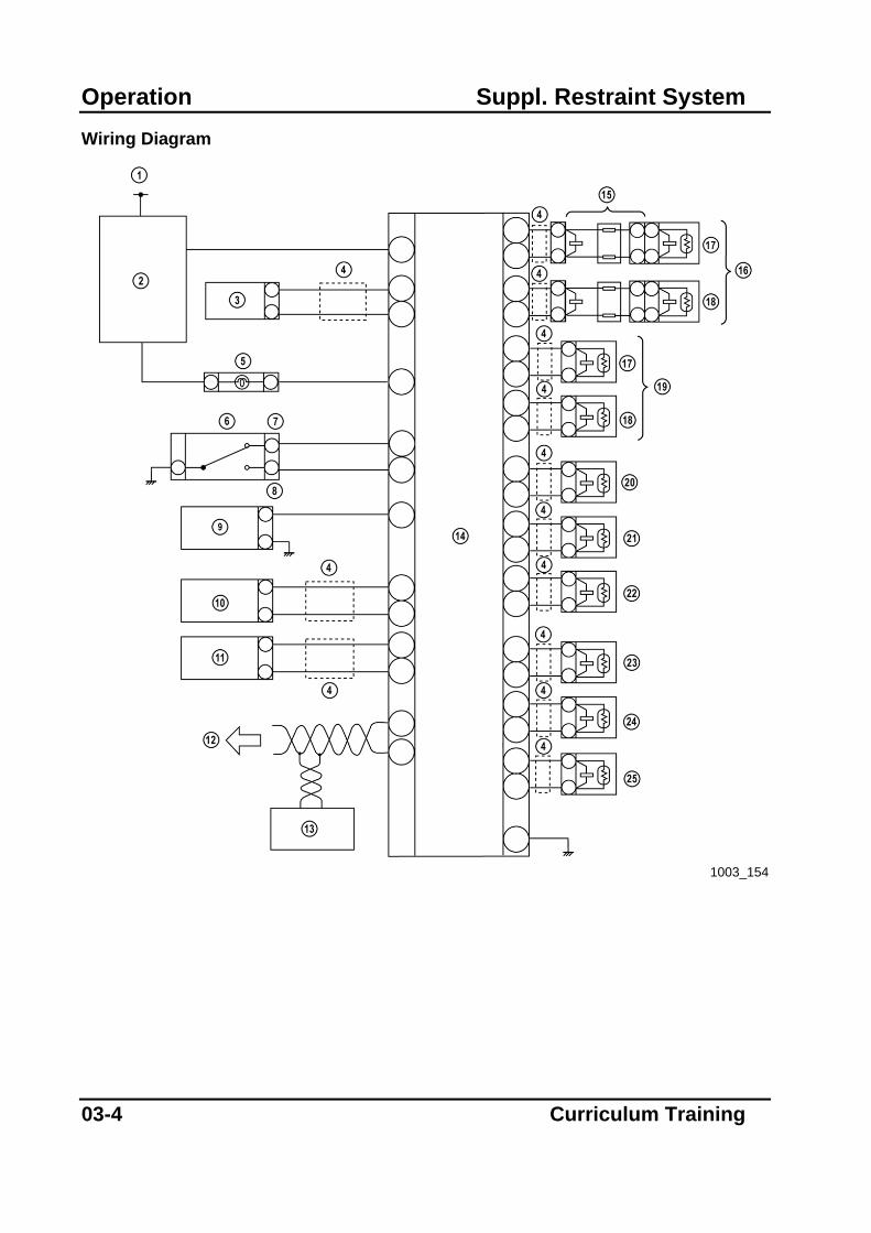
Operation Suppl. Restraint System Wiring Diagram
1003_154
03-4 Curriculum Training
Suppl. Restraint System Operation
Curriculum Training 03-5
1 IG1 14 SAS module 2 PJB 15 Clock spring 3 Crash zone sensor 16 Driver front airbag 4 Twisted pair 17 Inflator No.1 5 PAD indicator 18 Inflator No.2 6 PAD switch 19 Passenger front airbag 7 PASS AIRBAG ON 20 Driver pretensioner 8 PASS AIRBAG OFF 21 Driver-side curtain airbag 9 Driver buckle switch 22 Driver side airbag 10 Driver side airbag sensor 23 Passenger pretensioner 11 Passenger side airbag sensor 24 Passenger curtain airbag 12 CAN bus 25 Passenger side airbag 13 Instrument cluster
Operation Suppl. Restraint System
03-6 Curriculum Training
Notes:

Suppl. Restraint System Diagnosis and Repair
Diagnosis and Repair
On Board Diagnostic System
• All Mazda SRS are equipped with an OBD (On-Board Diagnostic) system that is integrated in the SAS module. The OBD system monitors the different SRS components for electrical faults. If a fault has been detected this is displayed via the SRS warning light.
• Each malfunction is stored in a non-volatile memory of the SAS module and may result in a deactivation of deployable SRS components. In this case the driver is strongly requested to bring the vehicle to the workshop to have the system be repaired.
• The OBD system starts operating automatically when the ignition switch is turned to the ON position.
• Mazda currently uses three basically different OBD systems:
– OBD system of the 1st SRS generation
– OBD system of the 2nd SRS generation
– OBD system of the 3rd SRS generation NOTE: The OBD system of the 1st SRS generation has no memory function for past DTCs,
i.e. the SRS warning light only indicates present malfunctions. The only Mazda model that still features this system is the B-Series (UN). Since the introduction of the Mazda 323 (BJ) in 1998 each other SAS module is equipped with a memory function for past DTCs.
NOTE: Always follow carefully the safety warnings and instructions stated in this training
manual and in the respective W/M, while working on the SRS. NOTE: Each SAS module has a back-up power supply to ensure the operation of the SRS
system for a certain time in case the battery power supply is cut during an accident. Condensers provide the back-up power supply. It is very important to deplete the back-up power before you start disconnecting or measuring on any circuit. Follow the specific instructions stated in the W/M regarding the depletion of the back-up power. Failure to follow those instructions may result in personal injury or even death.
Curriculum Training 04-1

Diagnosis and Repair Suppl. Restraint System
OBD System of the 2nd SRS Generation
• The OBD system of the 2nd SRS generation comprises the following features:
– Malfunction detection function.
– Display function to indicate present and past malfunctions as two-digit DTCs via the SRS warning light.
– DTC memory function for present and past malfunctions.
– Diagnosis via DLC-1.
– Fail-safe function to prevent the accidental activation of SRS components in case of a malfunction.
• The OBD system of the 2nd SRS generation is used in the following vehicles:
– MX-5 (NB), MPV (LW) and Premacy (CP). Present Malfunctions
• When the SRS warning light flashes or illuminates, the OBD system has detected a present malfunction and thus outputs a corresponding DTC. This DTC is also stored in the SAS module and will not be deleted when the battery is disconnected.
• To read out present DTCs, the ignition must be switched on. Then the SRS warning light will illuminate for 4…8 s, before it starts to display the two-digit DTCs as a corresponding flashing pattern.
• If the OBD system has detected more than one malfunction the stored DTCs are displayed consecutively beginning with the lowest code.
NOTE: The description of the DTCs and the recommended diagnostic procedures can be
found in the respective W/M.
04-2 Curriculum Training
Suppl. Restraint System Diagnosis and Repair
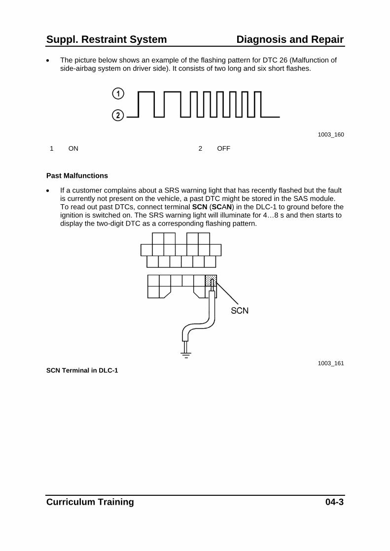
• The picture below shows an example of the flashing pattern for DTC 26 (Malfunction of side-airbag system on driver side). It consists of two long and six short flashes.
1003_160
1 ON 2 OFF
Past Malfunctions
• If a customer complains about a SRS warning light that has recently flashed but the fault is currently not present on the vehicle, a past DTC might be stored in the SAS module. To read out past DTCs, connect terminal SCN (SCAN) in the DLC-1 to ground before the ignition is switched on. The SRS warning light will illuminate for 4…8 s and then starts to display the two-digit DTC as a corresponding flashing pattern.
1003_161
SCN Terminal in DLC-1
Curriculum Training 04-3
Diagnosis and Repair Suppl. Restraint System
• Delete the stored DTCs from the memory of the SAS module after the repair is completed. Therefore: 1. Turn the ignition switch to the ON position. 2. Wait until the SRS warning light illuminates approx. 6 seconds and goes off. 3. Perform both the following steps alternately three times each at 0.5…1.0 seconds
intervals.
– Use a jumper wire to short the DLC terminal SCN to ground.
– Disconnect the jumper wire from ground. 4. If the DTCs are displayed, wait until they disappear. 5. Repeat the past malfunction inspection procedure to ensure that all past
malfunctions are deleted. 6. Turn the ignition switch to LOCK position. 7. Disconnect the jumper wire from the DLC.
NOTE: If the SRS warning light does not illuminate or remains illuminated when the ignition
switch is turned to the ON position, inspect the control circuit of the SRS warning light.
OBD of the 3rd SRS Generation
• The OBD system of the 3rd SRS generation comprises the following features:
– Malfunction detection function.
– Display function to indicate present malfunctions as two-digit DTCs via the SRS warning light.
– DTC memory function for present and past malfunctions.
– Diagnosis via DLC-2 and WDS.
– PID monitor function to access certain data such as input signals, calculated values and system status information.
– Fail-safe function to prevent the accidental activation of SRS components in case of an air bag system malfunction.
• The OBD system is used for the SRS installed in the following vehicles:
– Mazda2 (DY), Mazda3 (BK), Mazda6 (GG/GY), Tribute (EP) and RX-8 (SE)
04-4 Curriculum Training
Suppl. Restraint System Diagnosis and Repair
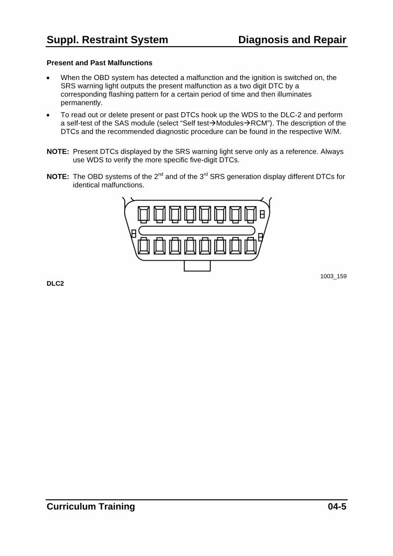
Present and Past Malfunctions
• When the OBD system has detected a malfunction and the ignition is switched on, the SRS warning light outputs the present malfunction as a two digit DTC by a corresponding flashing pattern for a certain period of time and then illuminates permanently.
• To read out or delete present or past DTCs hook up the WDS to the DLC-2 and perform a self-test of the SAS module (select “Self test Modules RCM”). The description of the DTCs and the recommended diagnostic procedure can be found in the respective W/M.
NOTE: Present DTCs displayed by the SRS warning light serve only as a reference. Always
use WDS to verify the more specific five-digit DTCs. NOTE: The OBD systems of the 2nd and of the 3rd SRS generation display different DTCs for
identical malfunctions.
1003_159
DLC2
Curriculum Training 04-5
Diagnosis and Repair Suppl. Restraint System
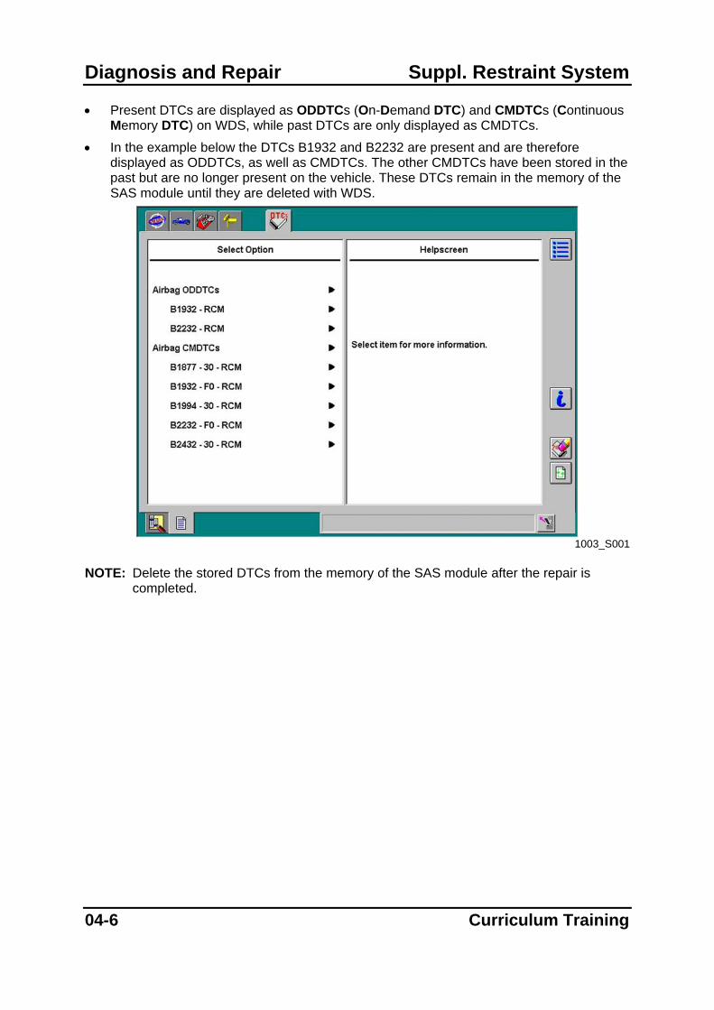
• Present DTCs are displayed as ODDTCs (On-Demand DTC) and CMDTCs (Continuous Memory DTC) on WDS, while past DTCs are only displayed as CMDTCs.
• In the example below the DTCs B1932 and B2232 are present and are therefore displayed as ODDTCs, as well as CMDTCs. The other CMDTCs have been stored in the past but are no longer present on the vehicle. These DTCs remain in the memory of the SAS module until they are deleted with WDS.
1003_S001
NOTE: Delete the stored DTCs from the memory of the SAS module after the repair is
completed.
04-6 Curriculum Training

Suppl. Restraint System Diagnosis and Repair
PID Monitor Function
• The PID (Parameter IDentification) monitor function allows to display the status of system parameters using the Datalogger of WDS.
PID Name (definition) Unit / Condition Condition/specification SAS
pin
CONT_RCM (Number of continuous DTC) — DTC is detected: 1- 255
DTC is not detected: 0
DS1_STAT (Driver airbag (inflator No.1) circuit state)
NORMAL
OPEN
SHRT GND
SHRT B+
Related wiring harness normal: NORMAL Related wiring harness circuit open: OPEN Related wiring harness short to ground: SHRT GND Related wiring harness short to power supply: SHRT B+
1S, 1V
PS1_STAT (Passenger airbag (inflator No.1) circuit state)
NORMAL
OPEN
SHRT GND
SHRT B+
Related wiring harness normal: NORMAL Related wiring harness circuit open: OPEN Related wiring harness short to ground: SHRT GND Related wiring harness short to power supply: SHRT B+
1M, 1P
DABAGR (Driver airbag module (inflator No.1) resistance)
ohm Under any condition: 1.5—3.7 ohm 1S, 1V
PABAGR (Passenger airbag module (inflator No.1) resistance)
ohm Under any condition: 1.4—2.9 ohm 1M, 1P
1003_T001
Excerpt of PID table for Mazda6 NOTE: Depending on the vehicle various PIDs are available. The SRS use different PID
names for identical parameters. Refer to the respective W/M and WDS for the corresponding name / description.
Curriculum Training 04-7
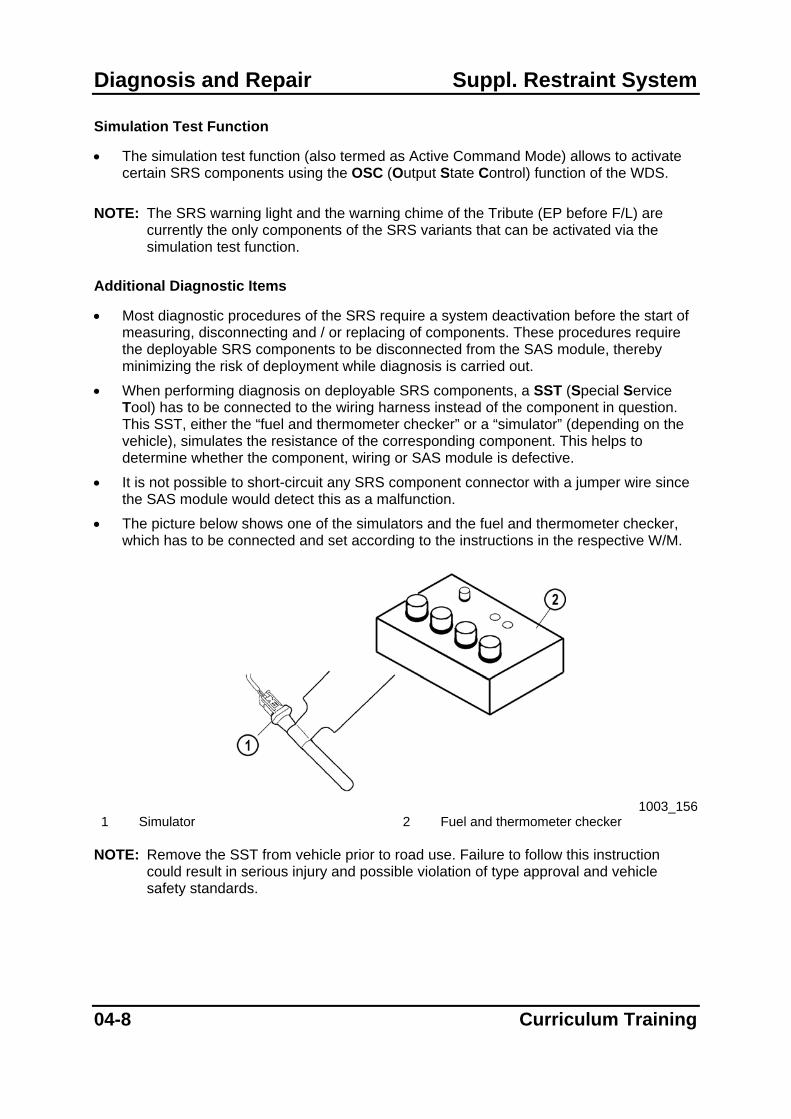
Diagnosis and Repair Suppl. Restraint System
Simulation Test Function
• The simulation test function (also termed as Active Command Mode) allows to activate certain SRS components using the OSC (Output State Control) function of the WDS.
NOTE: The SRS warning light and the warning chime of the Tribute (EP before F/L) are
currently the only components of the SRS variants that can be activated via the simulation test function.
Additional Diagnostic Items
• Most diagnostic procedures of the SRS require a system deactivation before the start of measuring, disconnecting and / or replacing of components. These procedures require the deployable SRS components to be disconnected from the SAS module, thereby minimizing the risk of deployment while diagnosis is carried out.
• When performing diagnosis on deployable SRS components, a SST (Special Service Tool) has to be connected to the wiring harness instead of the component in question. This SST, either the “fuel and thermometer checker” or a “simulator” (depending on the vehicle), simulates the resistance of the corresponding component. This helps to determine whether the component, wiring or SAS module is defective.
• It is not possible to short-circuit any SRS component connector with a jumper wire since the SAS module would detect this as a malfunction.
• The picture below shows one of the simulators and the fuel and thermometer checker, which has to be connected and set according to the instructions in the respective W/M.
1003_156
1 Simulator 2 Fuel and thermometer checker NOTE: Remove the SST from vehicle prior to road use. Failure to follow this instruction
could result in serious injury and possible violation of type approval and vehicle safety standards.
04-8 Curriculum Training

Suppl. Restraint System Diagnosis and Repair
Troubleshooting Example
• A customer brings his Mazda6 in the workshop with the complaint, that the SRS warning light is illuminated permanently after it has flashed for a short period.
• Switch on ignition to reproduce the concern. The light flashes DTC 19 for five times and then illuminates.
• Read out the DTCs of the SAS module. Connect WDS to DLC-2 and after the vehicle identification select “Toolbox Self test Modules RCM”.
• DTC B1932 (Driver airbag (inflator no.1) circuit resistance high) and DTC B2232 (Driver airbag module (inflator no.2) circuit resistance high) are displayed as ODDTCs and CMDTCs (see picture below).
NOTE: To simulate this concern both connectors S1-06 between driver-side airbag and
clock spring cable have been disconnected.
1003_S004
Curriculum Training 04-9

Diagnosis and Repair Suppl. Restraint System
• The next step is to find the description of the stored DTCs in the W/M and to carry out the respective troubleshooting procedure.
• The troubleshooting procedures for DTC B1932 and B2232 describe the detection condition for the faults and the following possible causes for the malfunction:
– Open or short circuit in the wiring between clock spring and SAS module.
– Clock spring malfunction.
– Driver air bag (inflator no.1 respectively inflator no.2) malfunction.
– SAS module malfunction. • Check the resistance value of the driver airbag circuit via the PIDs “DABGR” and
“D_ABGR2”. Monitor the PIDs of the SRS with WDS Datalogger. Select “Toolbox Datalogger Modules RCM”.
• Select the following PIDs from the PID selection menu:
– “DABGR” (Resistance of the driver airbag (inflator no.1))
– “D_ABGR2” (Resistance of the driver airbag (inflator no.2))
– “PABGR” (Resistance of the passenger airbag (inflator no.1))
– “CCNT_RCM” (Number of continuous DTCs)
– “DS1_STAT” (Driver airbag inflator no.1 circuit state)
– “DS2_STAT” (Driver airbag inflator no.2 circuit state)
– “PS1_STAT” (Passenger airbag inflator no.1 circuit state)
04-10 Curriculum Training
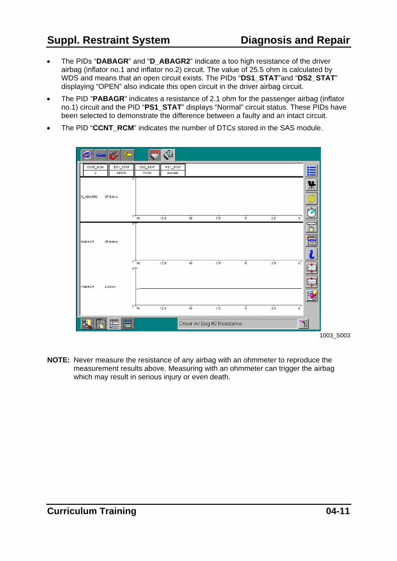
Suppl. Restraint System Diagnosis and Repair
• The PIDs “DABAGR” and “D_ABAGR2” indicate a too high resistance of the driver airbag (inflator no.1 and inflator no.2) circuit. The value of 25.5 ohm is calculated by WDS and means that an open circuit exists. The PIDs “DS1_STAT”and “DS2_STAT” displaying “OPEN” also indicate this open circuit in the driver airbag circuit.
• The PID ”PABAGR” indicates a resistance of 2.1 ohm for the passenger airbag (inflator no.1) circuit and the PID “PS1_STAT” displays “Normal” circuit status. These PIDs have been selected to demonstrate the difference between a faulty and an intact circuit.
• The PID “CCNT_RCM” indicates the number of DTCs stored in the SAS module.
1003_S003
NOTE: Never measure the resistance of any airbag with an ohmmeter to reproduce the
measurement results above. Measuring with an ohmmeter can trigger the airbag which may result in serious injury or even death.
Curriculum Training 04-11

Diagnosis and Repair Suppl. Restraint System
• The next step is to inspect the connectors between SAS module and driver airbag starting from the airbag side. Find the location of these connectors with the aid of the W/D.
1003_155
Excerpts from Mazda6 W/D
04-12 Curriculum Training
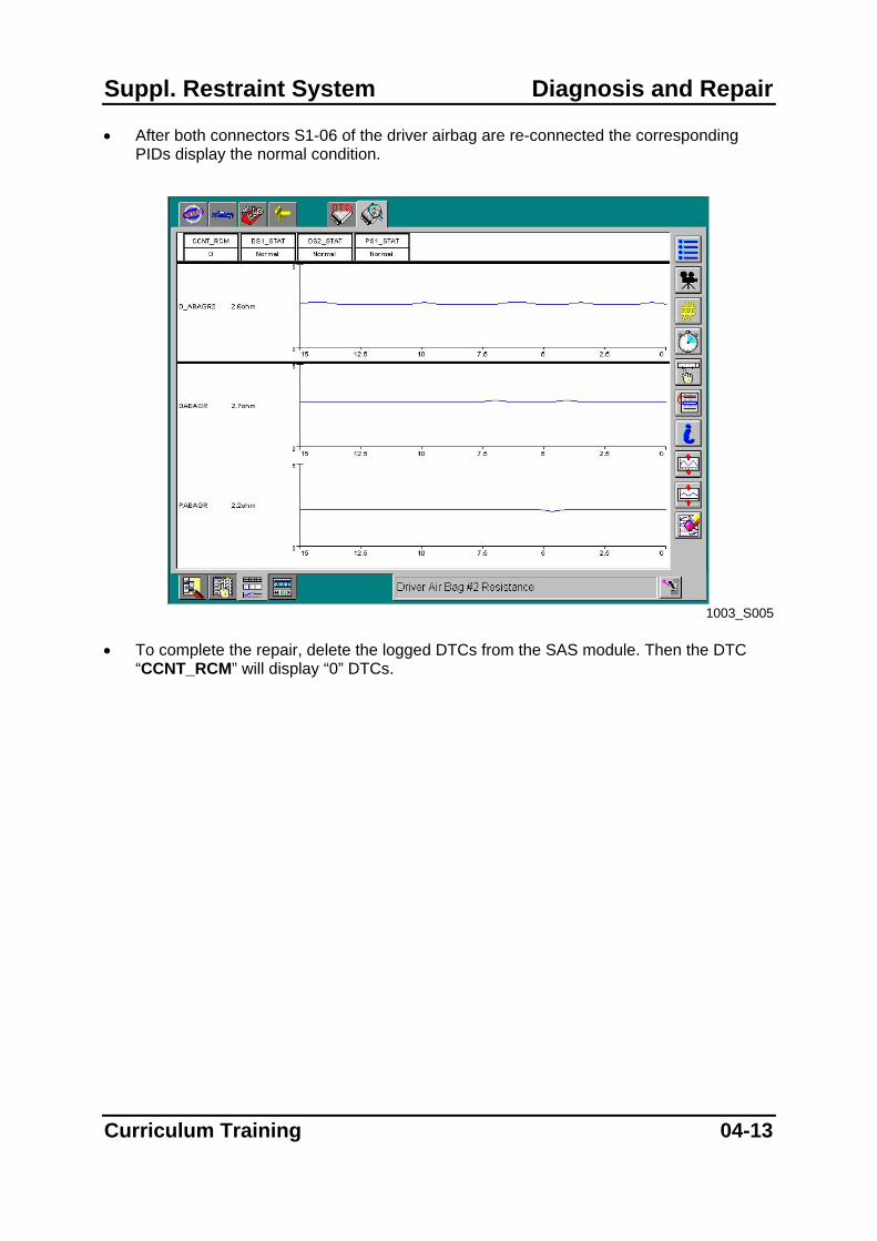
Suppl. Restraint System Diagnosis and Repair
• After both connectors S1-06 of the driver airbag are re-connected the corresponding PIDs display the normal condition.
1003_S005
• To complete the repair, delete the logged DTCs from the SAS module. Then the DTC
“CCNT_RCM” will display “0” DTCs.
Curriculum Training 04-13
Diagnosis and Repair Suppl. Restraint System
SRS Component Replacement
• Depending on the vehicle and the components that have been triggered during an accident the SAS module, crash zone sensor and side airbag sensor have to be checked or replaced.
NOTE: For the replacement of SRS components always refer to the procedures and service
warnings in the W/M. The following description of the SRS component replacement only serves as additional information.
Side Airbag Sensor Replacement on the Mazda3 / RX-8
• The side airbag sensors on Mazda3 (BK) and RX-8 (SE) vehicles have to be programmed by the SAS module after replacement. If the programming procedure is canceled accidentally, the sensor has to be replaced again.
• The following procedure explains how to replace a side airbag sensor on the Mazda3: 1. Replace the side airbag sensor according to the safety instructions stated in the
respective W/M. 2. Turn the ignition switch to the ON position for 5 s or more.
NOTE: The programming procedure will be canceled accidentally, if:
– The ignition switch is not held in the ON position for 5 s or more.
– The engine is started.
3. Verify that the SRS warning light illuminates for approx. 6 s and goes out. 4. If the airbag system warning light does not operate normally, refer to the OBD
system and perform inspection of the system as described in the W/M.
04-14 Curriculum Training
Suppl. Restraint System Diagnosis and Repair
SAS Module
• For the replacement of the SAS module of the 2nd and 3rd SRS generation different procedures are required.
SAS Module Replacement (2nd SRS Generation)
1. Replace the SAS module according to the safety instructions stated in the respective W/M.
2. Turn the ignition switch to the ON position and verify that the SRS warning light flashes continuously. If it does not flash, the OBD system has detected a malfunction.
3. Turn the ignition switch to the OFF position for more than 1 s and switch it back to the ON position (=Deployment Authorization Procedure).
4. Verify that the SRS warning light illuminates for approximately 6 s and then goes off. If the light stays on repeat the Deployment Authorization Procedure.
5. Verify that no DTC is logged in the SAS module. If necessary perform the applicable DTC troubleshooting procedure.
Curriculum Training 04-15
Diagnosis and Repair Suppl. Restraint System
SAS Module Replacement with WDS (3rd SRS Generation)
• The installation of a new SAS module requires configuration data to be transferred from the old module. Therefore, the WDS function “Programmable Module Installation” must be used for the replacement of the SAS module as described in the following: 1. Connect the WDS to the DLC2 and start the vehicle identification process. During
that process the WDS retrieves the configuration data from all programmable modules.
2. Select “Module programming Programmable module installation RCM” from the WDS Toolbox menu.
3. WDS will request you to replace the module. Replace the SAS module according to the safety instructions stated in the respective W/M.
4. Follow the instructions of WDS to finish the configuration of the SAS module. 5. Verify that no DTC is logged in the SAS module. If necessary perform the applicable
DTC troubleshooting procedure. NOTE: Always perform the vehicle identification with WDS before the replacement of the
SAS module. NOTE: Save a session of the vehicle before starting the programming procedure. Therefore
establish and end the session with the option “Hold (saves recordings)”. Then establish communication again without reactivating the held session and conduct the desired programming function. If the upload process fails and a module is left blank, the held session can be used to program this module.
NOTE: If accidentally the ignition is turned off or the 16-pin DLC cable is disconnected
during the upload process, an error message asking “Do you wish to retry?” will appear. Press YES as this will allow WDS to recover the error, that was encountered during the programming function. Pressing NO may result in the module being left blank.
04-16 Curriculum Training
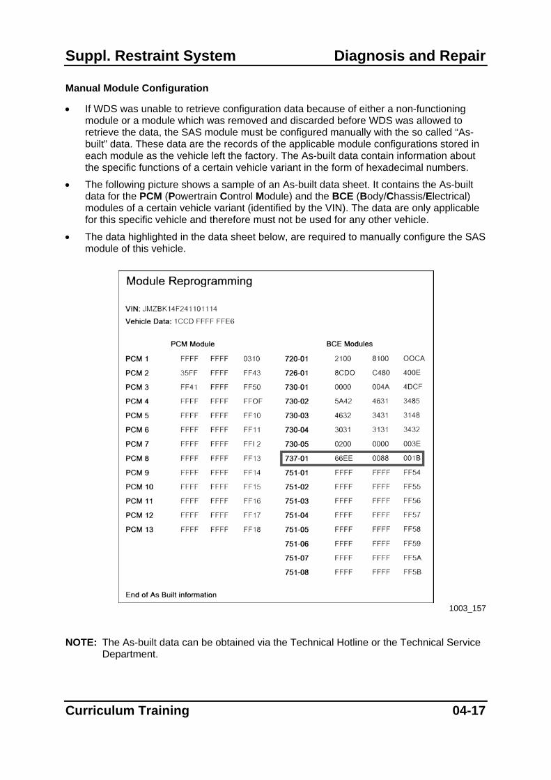
Suppl. Restraint System Diagnosis and Repair
Manual Module Configuration
• If WDS was unable to retrieve configuration data because of either a non-functioning module or a module which was removed and discarded before WDS was allowed to retrieve the data, the SAS module must be configured manually with the so called “As-built” data. These data are the records of the applicable module configurations stored in each module as the vehicle left the factory. The As-built data contain information about the specific functions of a certain vehicle variant in the form of hexadecimal numbers.
• The following picture shows a sample of an As-built data sheet. It contains the As-built data for the PCM (Powertrain Control Module) and the BCE (Body/Chassis/Electrical) modules of a certain vehicle variant (identified by the VIN). The data are only applicable for this specific vehicle and therefore must not be used for any other vehicle.
• The data highlighted in the data sheet below, are required to manually configure the SAS module of this vehicle.
1003_157
NOTE: The As-built data can be obtained via the Technical Hotline or the Technical Service
Department.
Curriculum Training 04-17

Diagnosis and Repair Suppl. Restraint System
• If As-built data are required for module configuration, the WDS displays a screen with the module identification code and three boxes for the hexadecimal numbers. After matching the module identification code (in this example 737-01) with the identical code on the As-built data sheet the corresponding hexadecimal numbers (in this example: 66EE 0088 001B) can be entered into the three boxes.
1003_S007
• After pressing the Tick button the programming process begins automatically and a
bargraph appears indicating the progress. NOTE: Do not configure a module by downloading configuration data from another vehicle of
similar build and uploading it into the vehicle concerned. This may create problems as configurable modules are only working properly if they are configured according to the appropriate data specified by each VIN. In addition, this procedure may also transfer the VIN logged in the module from one vehicle to another.
04-18 Curriculum Training
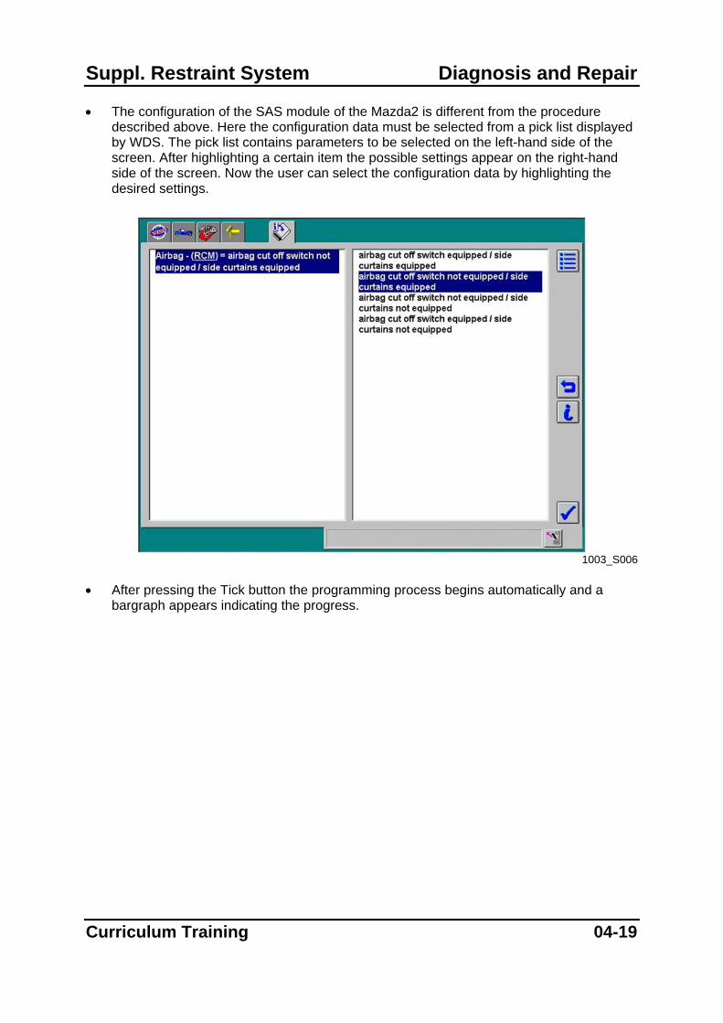
Suppl. Restraint System Diagnosis and Repair
• The configuration of the SAS module of the Mazda2 is different from the procedure described above. Here the configuration data must be selected from a pick list displayed by WDS. The pick list contains parameters to be selected on the left-hand side of the screen. After highlighting a certain item the possible settings appear on the right-hand side of the screen. Now the user can select the configuration data by highlighting the desired settings.
1003_S006
• After pressing the Tick button the programming process begins automatically and a
bargraph appears indicating the progress.
Curriculum Training 04-19
Diagnosis and Repair Suppl. Restraint System
Notes:
04-20 Curriculum Training

Suppl. Restraint System List of Abbreviations
ALR Automatic Locking Retractor
AC Alternating Current CAN Controller Area Network DC Direct Current DLC Data Link Connector DTC Diagnostic Trouble Code ELR Emergency Locking
Retractor HS-CAN High Speed – Controller
Area Network OBD On-Board-Diagnostics PID Parameter IDentification RKE Remote Keyless Entry SAS Sophisticated Airbag
Sensor SI Service Information SRS Supplemental Restraint
System
SCN SCAN SST Special Service Tool VIN Vehicle Identification
Number W/D Wiring Diagram WDS Worldwide Diagnostic
System W/M Workshop Manual
Curriculum Training 05-1