supplemental seismic report for centre block, …
TRANSCRIPT
SUPPLEMENTAL SEISMIC REPORT FOR
CENTRE BLOCK, PARLIAMENT HILL
Work Package 3
Prepared for: Public Works and Government Services Canada
Parliamentary Precinct Branch
Prepared by: Halsall Associates
210 Gladstone Avenue, Suite 4001 Ottawa, Ontario
K2P 0Y6 (613) 237-2462
14Y160-113A
May 2015
SUPPLEMENTAL SEISMIC REPORT
FOR
CENTRE BLOCK, PARLIAMENT HILL
Work Package 3
PWGSC Client Reference Number: 20150336
Prepared for: Public Works and Government Services Canada
Parliamentary Precinct Branch
Prepared by: Halsall Associates
210 Gladstone Avenue, Suite 4001 Ottawa, ON K2P 0Y6
613-237-2462
14Y160-113A
May 2015
14Y160-113A Supplemental Seismic Report for Centre Block i
TABLE OF CONTENTS LIST OF ACRONYMS .......................................................................................................................... III 1. EXECUTIVE SUMMARY ........................................................................................................ IV
2. INTRODUCTION ................................................................................................................... 1
2.1 Scope ....................................................................................................................................... 1
2.2 Limitations ............................................................................................................................... 2
2.3 Existing Documents ................................................................................................................. 2
2.4 General Description of the Structure and Site ........................................................................ 3
2.4.1 Centre Block Main Building ........................................................................................................... 3 2.4.2 Peace Tower ................................................................................................................................... 4
3. CHALLENGES, RISKS AND OPPORTUNITIES ......................................................................... 5
4. FURTHER INVESTIGATIONS .................................................................................................. 8
4.1 Structure & geometry .............................................................................................................. 8
4.2 Material properties .................................................................................................................. 9
4.3 Geotechnical .......................................................................................................................... 10
4.4 Non-structural components ................................................................................................... 10
5. POTENTIAL CENTRE BLOCK SEISMIC UPGRADE METHODS ................................................ 12
5.1 Centre Block Seismic Upgrade Introduction .......................................................................... 12
5.2 Centre Block Conventional Seismic Upgrade ........................................................................ 12
5.2.1 Description of Conventional Seismic Upgrade .......................................................................... 12 5.2.2 Feasibility of Conventional Seismic Upgrade ............................................................................. 14 5.2.3 Advantages of a Conventional Seismic Upgrade ....................................................................... 15 5.2.4 Disadvantages of a Conventional Seismic Upgrade.................................................................. 15 5.2.5 Risks of a Conventional Seismic Upgrade ................................................................................. 15 5.2.6 Heritage Impact of a Conventional Seismic Upgrade ................................................................ 16
5.3 Centre Block Base Isolation Seismic Upgrade ...................................................................... 16
5.3.1 Description of a Base Isolation Seismic Upgrade...................................................................... 16 5.3.2 Feasibility of a Base Isolation Seismic Upgrade ........................................................................ 19 5.3.3 Advantages of a Base Isolation Seismic Upgrade ..................................................................... 20 5.3.4 Disadvantages of a Base Isolation Seismic Upgrade ................................................................ 21 5.3.5 Risks of Base Isolation Seismic Upgrade ................................................................................... 21 5.3.6 Heritage Impact of a Base Isolation Seismic Upgrade .............................................................. 22
5.4 Comparison of Conventional Seismic Upgrade versus Base Isolation for the Centre Block . 22
6. POTENTIAL PEACE TOWER SEISMIC UPGRADE METHODS .................................................. 24
6.1 Peace Tower Seismic Upgrade Introduction .......................................................................... 24
6.2 Peace Tower Conventional Seismic Upgrades ...................................................................... 24
6.2.1 Spandrel Beam Upgrade Methods ............................................................................................. 24 6.2.2 Pier Upgrade Methods ................................................................................................................. 25
14Y160-113A Supplemental Seismic Report for Centre Block ii
6.2.3 Upper Tower Upgrade Methods .................................................................................................. 25 6.2.4 Peace Tower Conventional Seismic Upgrade Feasibility ........................................................... 26 6.2.5 Advantages of a Peace Tower Conventional Seismic Upgrade ................................................ 26 6.2.6 Disadvantages of a Peace Tower Conventional Seismic Upgrade ........................................... 26 6.2.7 Peace Tower Conventional Seismic Upgrade Risks .................................................................. 27 6.2.8 Peace Tower Conventional Seismic Upgrade Heritage Impacts ............................................... 27
6.3 Peace Tower Base Isolation Seismic Upgrades ..................................................................... 27
6.3.1 Peace Tower Base Isolation Method .......................................................................................... 27 6.3.2 Peace Tower Base Isolation Feasibility ...................................................................................... 28 6.3.3 Advantages of a Peace Tower Base Isolation Seismic Upgrade ............................................... 28 6.3.4 Disadvantages of a Peace Tower Base Isolation Seismic Upgrade ......................................... 29 6.3.5 Peace Tower Base Isolation Risks .............................................................................................. 29 6.3.6 Peace Tower Base Isolation Heritage Impact ............................................................................ 29
6.4 Comparison of Conventional Seismic Upgrade versus Base Isolation for the Peace Tower . 29
7. SEISMIC RETROFIT OF OPERATIONAL AND FUNCTIONAL COMPONENTS............................. 31
7.1 Typical Restraint Methods ..................................................................................................... 31
7.1.1 Suspended equipment ................................................................................................................ 31 7.1.2 Wall-mounted equipment ............................................................................................................ 31 7.1.3 Base-mounted equipment .......................................................................................................... 32 7.1.4 Partition walls .............................................................................................................................. 32 7.1.5 Exterior Elements ........................................................................................................................ 32
7.2 Description of Items Requiring Restraint .............................................................................. 32
7.2.1 Terra Cotta Tiles ........................................................................................................................... 33 7.2.2 Ceilings ......................................................................................................................................... 33 7.2.3 Skylights ....................................................................................................................................... 33 7.2.4 Decorative Arches ........................................................................................................................ 34 7.2.5 Walls ............................................................................................................................................. 34 7.2.6 Sculptures .................................................................................................................................... 34 7.2.7 Light fixtures ................................................................................................................................ 35 7.2.8 Exterior ......................................................................................................................................... 35 7.2.9 Additional Peace Tower Components ......................................................................................... 36
7.3 Seismic Restraint Requirements According to the 2015 NBCC ............................................ 36
7.4 Seismic Restraint Requirements for Base Isolated Structures ............................................. 36
8. CONCLUSIONS .................................................................................................................. 38
8.1 Challenges, Opportunities and Risks ..................................................................................... 38
8.2 Further Investigations ............................................................................................................ 38
8.3 Potential Seismic Upgrade Methods ..................................................................................... 38
8.3.1 Centre Block and Peace Tower Seismic Upgrade Methods ...................................................... 38 8.3.2 Operational and Function Components ..................................................................................... 39

14Y160-113A Supplemental Seismic Report for Centre Block iii
LIST OF ACRONYMS
CBUS Centre Block Underground Services FRP Fibre Reinforced Polymer NBCC National Building Code of Canada PWGSC Public Works and Government Services Canada RPS Real Property Services
14Y160-113A Supplemental Seismic Report for Centre Block iv
1. EXECUTIVE SUMMARY
1.1 Scope
In July 2014, Halsall Associates was engaged by PWGSC to complete a preliminary seismic assessment of the Centre Block on Parliament Hill in the context of the requirements of the latest edition of the National Building Code of Canada (2010 NBCC) and the Real Property Service (RPS) Policy on Seismic Resistance of PWGSC Buildings. Halsall was also engaged to complete research on potential options to seismically rehabilitate heritage buildings based on work done on buildings, both nationally and internationally, that are of a similar scale, type and importance as the Centre Block, as well as to present further investigations and specific upgrade options for the Centre Block.
This report, for Work Package 3 – Supplemental Seismic Report for Centre Block, focusses on identifying further investigations, presenting seismic upgrade options and discussing risks, challenges and opportunities associated with those upgrade options.
1.2 General Description of Structure
The Centre Block is comprised of three connected components: the main Centre Block building, the Peace Tower and the Library of Parliament. This report considers only the Centre Block and Peace Tower. The Centre Block is a 6 storey building over one basement storey level and is comprised of brick, stone masonry, steel and concrete. It was constructed between 1916 and 1920. The upper floor structure is typically comprised of a cementitious topping on terra cotta flat arches that are supported on steel beams. The steel beams are typically supported on either steel columns or unreinforced stone and brick masonry walls. The lowest floor structure is reinforced concrete, while the sloped roof structure is typically expanded metal forms with a cementitious topping on sloping steel beams. The foundations generally consist of unreinforced concrete piers and walls bearing directly on limestone rock.
The Peace Tower was constructed between 1919 and 1927, with an approximate height of 92 m. It is connected to the Centre Block by a structural link at the first two stories. The Peace Tower is supported by unreinforced concrete piers and walls, with an integrally built outer wythe of stone masonry. The piers bear directly on limestone rock.
1.3 Challenges, Risks and Opportunities
The primary challenges in completing a seismic retrofit include working around heritage finishes, finding locations for concrete walls or braced frames within the Centre Block, and working with incomplete information of such a complex building.
Risks of a seismic upgrade include damage to heritage finishes or structure, uncovering deterioration or unforeseen conditions during construction, or causing unintentional damage through the introduction of new structural elements.
There are opportunities to insert new mechanical or electrical services in conjunction with the upgrade, to incorporate part of the upgrade structure into new functional space and to expand the scope of work in the basement to insert transfer beams and remove columns. There is also an
14Y160-113A Supplemental Seismic Report for Centre Block v
opportunity to include innovative structural solutions to save time and money or to provide an additional level of performance beyond the minimum life safety requirements (such as additional protection for heritage components).
1.4 Further Investigations
Gaps in the information available on the Centre Block and Peace Tower were noted in Work Package 2. Further investigations are recommended to reduce the number of gaps and refine the seismic analysis results. Exploratory openings or non-destructive testing should be used to confirm structural dimensions, connections and configurations. Material testing should be completed to assess unknown properties of the masonry, concrete and cementitious materials. A detailed geotechnical investigation should be completed. Connection details of many non-structural components should be determined.
1.5 Potential Seismic Upgrade Methods
Seismic upgrade options for the Centre Block and Peace Tower can be broadly divided into two categories: base isolation and conventional reinforcing methods. Base isolation seeks to reduce the level of seismic demand on the structure via the insertion of a system of “springs” between the structure and its foundations. The majority of the work could take place in the basement of the structures. Conventional reinforcing methods include adding concrete walls or steel braced frames for the Centre Block, and steel or FRP reinforcing for the Peace Tower.
Both categories provide an increased level of safety in a seismic event by preventing collapse. Base isolation can provide effective seismic protection of the heritage elements as well as a Post-Disaster level of performance. Conventional reinforcing methods do not offer significant protection of heritage elements and it would be difficult to achieve a Post-Disaster level of performance for this building.
Conventional reinforcing methods, and base isolation to a lesser extent, will require an upgrade to the Centre Block’s floor and roof diaphragms. Base isolation will also require a ‘moat’ around the perimeter of the building. A seismic joint between the Centre Block, Peace Tower and other adjoining structures will be required to prevent damage in a seismic event. The size of the joint is minimized with conventional reinforcing methods or if the adjoining structures are base isolated together.
It is important to note that decisions to seismically upgrade either the Centre Block main building or Peace Tower should not be made in isolation from each other. Due their attachment and proximity, collapse or damage of one structure from a seismic event, may, in the worst case, cause collapse of the other structure, or at best, cause the other structure to be unable to be occupied, regardless of the other structure’s level of seismic performance.
1.6 Seismic Restraint of Operational and Functional Components
Suspended items such ceilings, catwalks and light fixtures should be restrained by installing angled cables or struts. Partitions should be reinforced and connected to the structure for out-of-plane motion. Sculptures, equipment, chimneys and other decorative items should be positively anchored to the structure. Items that could fall during a seismic event, such as fireproofing tiles on the steel beams and skylights should be restrained. Base isolation will largely reduce the need for seismic restraint, except for items that are subject to vertical accelerations, such as grotesques and ceilings.

14Y160-113A Supplemental Seismic Report for Centre Block vi
1.7 High Level Seismic Upgrade Cost
In the additional report prepared by Halsall, entitled “High Level Seismic Upgrade Cost Estimate for Centre Block, Parliament Hill”, the estimated structural cost for the conventional upgrade method is approximately $135,000,000. The estimated structural cost for the seismic isolation upgrade method is approximately $99,000,000. These costs are for structural items only and exclude any contingencies, fees, general conditions and taxes. For a complete description of the costing methodology and exclusions, please refer to the referenced report.

14Y160-113A Supplemental Seismic Report for Centre Block Page 1
2. INTRODUCTION
2.1 Scope
In July 2014, Halsall Associates was engaged by PWGSC to complete a preliminary seismic assessment of the Centre Block on Parliament Hill in the context of the requirements of the latest edition of the National Building Code of Canada (2010 NBCC) and the Real Property Service (RPS) Policy on Seismic Resistance of PWGSC Buildings. Halsall was also engaged to complete targeted research on potential options to seismically rehabilitate heritage buildings based on work done on buildings, both nationally and internationally, that are of a similar scale, type and importance as the Centre Block, as well as to present further investigations and specific upgrade options for the Centre Block.
Our services include the following:
a) Research and present potential options for the seismic rehabilitation of heritage buildings based on previous work done on other structures with similar design, importance and earthquake forces, both nationally and internationally.
b) Conduct a gap analysis to determine what information of the building construction, materials and structural systems is missing from the available documentation and research and that would be required to complete a detailed seismic analysis in a separate study.
c) Determine the ability of the Centre Block to resist the seismic loads as specified in 2010 NBCC based on a preliminary analysis of the building structure.
d) Determine the ability of the non-structural and secondary structural elements to resist the seismic loads as specified in the 2010 NBCC based on a qualitative assessment.
e) Compare the proposed 2015 NBCC draft seismic loads to the 2010 NBCC loads and discuss the impact of revised loads on the preliminary seismic assessment.
f) Identify potential seismic upgrade options based on the results of the preliminary seismic analysis.
g) Identify potential opportunities, challenges and risks associated with completing a seismic upgrade of the Centre Block, including the potential lowering of the Centre Block basement and other adjacent construction projects.
This report, for Work Package 3 – Supplemental Seismic Report, focusses on presenting the challenges, risks and opportunities in the seismic upgrading of the Centre Block, discussing further investigations that are required to achieve a more complete seismic analysis of the structure, and identifying potential upgrade and retrofit options.
14Y160-113A Supplemental Seismic Report for Centre Block Page 2
2.2 Limitations
No party other than the Client shall rely on the Consultant’s work without the express written consent of the Consultant. The scope of work and related responsibilities are defined in the Conditions of Assignment. Any use which a third party makes of this work, or any reliance on or decisions to be made based on it, are the responsibility of such third parties. Decisions made or actions taken as a result of our work shall be the responsibility of the parties directly involved in the decisions or actions. Any third party user of this report specifically denies any right to any claims, whether in contract, tort and/or any other cause of action in law, against the Consultant (including Sub-Consultants, their officers, agents and employees).
The work reflects the Consultant’s best judgment in light of the information reviewed by them at the time of preparation. Unless otherwise agreed in writing by Halsall, it shall not be used to express or imply warranty as to the fitness of the property for a particular purpose. This is not a certification of compliance with past or present regulations. No portion of this report may be used as a separate entity; it is written to be read in its entirety.
This work does not wholly eliminate uncertainty regarding the potential for existing or future costs, hazards or losses in connection with a property. No physical or destructive testing and no design calculations have been performed unless specifically recorded. Conditions existing but not recorded were not apparent given the level of study undertaken. Only conditions actually seen during examination of representative samples can be said to have been appraised and comments on the balance of the conditions are assumptions based upon extrapolation. We can perform further investigation on items of concern if so required.
Only the specific information identified has been reviewed. The Consultant is not obligated to identify mistakes or insufficiencies in the information obtained from the various sources or to verify the accuracy of the information.
Halsall is not investigating or providing advice about pollutants, contaminants or hazardous materials.
Budget figures are our opinion of a probable current dollar value of the work and are provided for approximate budget purposes only. Accurate figures can only be obtained by establishing a scope of work and receiving quotes from suitable contractors.
Time frames given for undertaking work represent our opinion of when to budget for the work. Failure of the item, or the optimum repair/replacement process, may vary from our estimate.
2.3 Existing Documents
The following existing documents were provided by PWGSC and were used:
• A variety of original architectural and structural drawings prepared by architects John Pearson and Jean-Omer Marchand, dated from 1916 to 1927;
• Original structural steel floor plan shop drawings prepared by the Dominion Bridge Co., dated to 1916;
14Y160-113A Supplemental Seismic Report for Centre Block Page 3
• Centre Block “As-Found” drawings, prepared by the Heritage Conservation Directorate, Professional and Technical Service Management and PWGSC in 2002;
• Various Centre Block and Peace Tower alteration drawings, including:
o Centre Block Underground Services Building;
o Centre Block Chimney Stabilization Phase I;
o Alterations & Additions Centre Block (1971 Courtyard Additions);
o Fullers Gargoyle repair;
o Extension to East & West Penthouses at South Corridor Elevators;
o Centre Block South – Conservation;
o Centre Block Phase 1 Renovations (1987 Stairwell extensions);
o Centre Block Ventilation Towers Rehabilitation Project;
o Peace Tower Alteration Parliament Hill (1980); and
o Peace Tower Conservation of Masonry (1994).
• Scans of selected specifications, construction reports and letters prepared by John Pearson during the original construction;
• Photographs from the original construction period and several more recent restoration and repair projects; and
• Various Centre Block and Peace Tower studies and reports.
2.4 General Description of the Structure and Site
2.4.1 Centre Block Main Building Construction of the Centre Block main building structure was carried out from 1916 to 1920, following the fire that destroyed much of the old Centre Block. The Centre Block is comprised of six above grade storeys and one below grade storey. The building is comprised primarily of two main east-west office corridors, called the North and South Corridors, which are connected at varying levels by five main volumes which are separated by internal courtyards: the House of Commons, Senate Chamber, East and West Office Blocks and the Hall of Honour (formerly Hall of Fame).
The floor structure of the Centre Block is typically comprised of flat terra cotta arches supported by structural steel beams, covered with a cementitious topping. Lateral spread of the beams due to the arching forces is prevented by steel tie rods between the beams. The two exceptions are the lowest
14Y160-113A Supplemental Seismic Report for Centre Block Page 4
framed level, which consists of reinforced concrete slabs and beams, and the sloped roof sections, which consist of a cementitious product placed over expanded metal forms supported on steel beams or steel trusses.
The floor structures are typically supported on load bearing masonry walls, except for some larger volumes which are supported on steel columns. The exterior masonry walls are primarily comprised of brick masonry built integrally with an outer wythe of stone masonry, while the interior load bearing masonry walls are comprised of only brick masonry. The foundations which support the walls and columns typically consist of unreinforced concrete piers and walls that bear directly on the rock. One exception occurs in the Southeast corner of the building, where the unreinforced concrete walls were constructed on top of the existing limestone foundation walls from the original Centre Block construction, rather than directly on the bedrock.
The Centre Block is connected to the Library of Parliament and CBUS structures, but the design of these structures is not specifically considered in this report.
Based on the preliminary desktop geotechnical study that was completed by Stantec Consulting, August 2014, PWGSC File No.fe173.EP764-150225, the Centre Block is believed to be founded directly on limestone bedrock.
2.4.2 Peace Tower The Peace Tower was constructed between 1919 and 1927, with an approximate height of 92 m. It is a component of the overall Centre Block building and is linked to the main structure at the first two stories. The Peace Tower is supported primarily by 4 unreinforced concrete piers in the corners of the tower that are constructed integrally with an outer wythe of stone masonry. The piers are connected by unreinforced concrete walls with a similar outer wythe of stone masonry that are punctuated by numerous openings. The piers are supported on unreinforced concrete foundations that bear directly on rock.
The floor structure of the Peace Tower typically consists of reinforced concrete slabs supported on structural steel beams encased in concrete, which bear on the concrete piers and walls. The sloped roof of the tower is comprised of reinforced concrete slabs, beams and piers.
Based on the preliminary desktop geotechnical study that was completed by Stantec Consulting, August 2014, PWGSC File No.fe173.EP764-150225, the Peace Tower is believed to be founded directly on limestone bedrock.
14Y160-113A Supplemental Seismic Report for Centre Block Page 5
3. CHALLENGES, RISKS AND OPPORTUNITIES
In the process of performing the seismic analysis of the Centre Block and Peace Tower, a number of challenges and risks associated with engaging in a seismic upgrade were identified. Opportunities to develop efficiencies or complete additional work on the structure were also examined.
Challenges in undertaking a seismic upgrade of the Centre Block and Peace Tower include:
a) Heritage finishes: In most of the Centre Block, the wall, ceiling and floor finishes are built tight to the structure. For example, most ceilings are composed of plaster applied directly to the terra cotta flat arches and steel beams of the floor structure, which does not provide any space under the structure in which to install new reinforcing. Difficulty working around or with heritage finishes will be a significant challenge for any seismic retrofit in highly finished areas;
b) Incomplete information: As discussed in the Gap Analysis in Work Package 2, there are many unknowns that can affect a seismic upgrade, such as material properties, structural geometries and properties of non-structural or secondary components. While steps can be taken to reduce the knowledge gaps, with such a complex building with such a variety of structural configurations, completely understanding the entire structure and all of its components will be a significant challenge;
c) Limited feasible locations for new structure: There are very few locations within the Centre Block for the insertion of new concrete walls or steel braces that would be acceptable from an architectural or heritage point of view. Establishing locations for the many shear walls or steel braces would present a significant challenge;
d) Secondary structural and non-structural elements: Identifying, analysing and restraining all of the secondary structural and non-structural elements will be challenging due to the complexity of the building and because many of these elements have heritage value; and
e) Modelling material properties: As with any unreinforced masonry structure, properly modelling the masonry material properties and understanding the implications of those properties on the performance of the building is a challenge to seismically upgrade the building to a set performance level.
Risks involved in a seismic upgrade on a heritage stone/masonry building include:
f) Damage to heritage features: During the installation of components of a seismic upgrade, there is the risk that heritage features or the structure itself may be accidentally damaged. For example, if anchors are drilled too far into a masonry/stone wall from the interior, the exterior stone could spall and break off. Additional damage during topping removal or from epoxy leaking during anchor installation is also possible. If the seismic retrofit option requires more work in proximity to heritage features, there is an increased risk of accidental damage;
14Y160-113A Supplemental Seismic Report for Centre Block Page 6
g) Deterioration of the structure: Elements of the structure that are not easily seen may be deteriorated, resulting in more extensive repairs than anticipated. For example, the floor structure in the Centre Block typically consists of terra cotta flat arches supported on structural steel beams, covered with a cementitious topping. The steel beams are typically embedded in the supporting masonry walls. Corrosion of the steel beams could be hidden at these locations. Other possible types of deterioration include weathering of stone and masonry, spalling of concrete and crumbling of masonry and mortar;
h) Unforeseen Conditions: As with most buildings, most of the structure is hidden behind finishes and the structural configurations vary significantly throughout the building according to the drawings. There is risk of unforeseen structural conditions (such as a different structural configuration than anticipated) that could cause additional costs and delays; and
i) Unintended consequences of a structural intervention: Due to the complexity and age of the structure, when new structural elements such as concrete walls, steel braces or anchors are introduced to the structure they may impose new restraint, or new openings may release restraint which may alter how the structure responds to lateral, gravity or thermal loading.
Opportunities include:
j) New mechanical and electrical services: Seismic upgrades offer the opportunity to incorporate new mechanical and electrical services into the structural upgrade elements. For example, openings for steel braces or columns can be adjusted to also allow mechanical ducts, and new concrete shear walls or slabs can incorporate conduits for electrical services;
k) Additional functional space: If there is intent to add functional space within the courtyards, there is an opportunity with a conventional seismic retrofit for new braces or shear walls to be incorporated into the new structure. If the Centre Block is base isolated, there also is an opportunity to significantly reduce the seismic demand on any new structure;
l) Basement columns: If foundation work is undertaken as a part of a seismic upgrade option, there is the opportunity to expand the work to include adding transfer beams at the ground floor level suspended concrete slab to reduce the number of columns in the basement; and
m) Innovative structural solutions: There is an opportunity to include innovative structural solutions that can save time and money in construction, or also provide additional performance targets that exceed the minimum life safety specifications of the NBCC (such as additional protection for heritage components).
Halsall Associates has also examined whether any seismic upgrade work that would be undertaken would present an opportunity to create more useable space in the Centre Block by excavating in the basement level. Our comments are as follows:
n) Any seismic upgrade involving the foundation walls or columns/piers (construction of a raft foundation or installation of base isolation) would be localized, and would therefore not

14Y160-113A Supplemental Seismic Report for Centre Block Page 7
require excavation on the scale of that are required to substantially lower the entire basement floor;
o) Both a basement lowering project and a base isolation project would involve shoring and jacking of the interior columns to allow for either lowering of the column footings or installation of seismic isolators. Some of the work involved in each project is therefore complimentary; and
p) The work required to lower the basement level and create more space could be carried out regardless of whether a seismic upgrade is completed or not.
14Y160-113A Supplemental Seismic Report for Centre Block Page 8
4. FURTHER INVESTIGATIONS
In the process of reviewing the documentation that was provided by PWGSC and performing the seismic analysis of the Centre Block and Peace Tower, gaps were noted in the information available that would affect the results of the seismic analysis. In Work Package 2, the gap analysis was presented and reasonable assumptions were made to cover these gaps and develop the conclusions, while upgrade options are discussed in this report. Further investigations, testing and analyses are recommended to address these gaps in information and increase the accuracy of the seismic analysis that was performed. These recommendations are presented below.
4.1 Structure & geometry
Further investigations recommended for Centre Block:
a) Fundamental periods of the structure: Having measured periods of the Centre Block components is a good way to verify the calculated stiffness of an analytical model. Monitoring will require excitation to produce valuable information, so better information can be obtained if the monitoring equipment is installed for longer amounts of time. Additionally, monitoring should occur at many locations throughout the building to determine if different parts of the building behave differently;
b) Thickness and composition of floor topping: Because Centre Block was built over the course of several years, it is possible that there exists some variability in the composition of the floor topping throughout the building. To obtain a representative sample of the floor topping composition, it is recommended that cores of the topping be made at different locations at each level of the Centre Block, which can be supplemented by the latest technologies in non-destructive testing;
c) Thickness of select walls throughout the building: As some of this information is incomplete due to missing or unclear drawings, the thickness of all unknown walls should be established with cores, which could be supplemented with the latest technologies in non-destructive testing;
d) Connections between select steel elements, such as collector beams for diaphragms: Exploratory openings at discrete locations are recommended to determine the actual capacity of steel connections that transfer lateral seismic loads to the masonry shear walls;
e) Steel to masonry and concrete to masonry connections: Exploratory openings at a sampling of locations are recommended to determine the condition of these connections and establish their capacity to transfer diaphragm loads to the shear walls;
f) Centre Block to Library of Parliament connection: Openings are recommended to determine whether there is an expansion joint between the two structures or a positive connection. If an expansion joint was used, the details of this joint are required to determine whether it is

14Y160-113A Supplemental Seismic Report for Centre Block Page 9
sufficient to accommodate the movement of the two structures. If there is a positive connection between Centre Block and the Library, the capacity of this connection should be determined;
g) Centre Block to Peace Tower connection: It is known that there is no expansion joint between the Peace Tower and Centre Block, however the details of the connection are unclear. Exploratory openings are recommended to determine the capacity of the connection;
h) Centre Block North Tower details: Exploratory openings, coring and measurements of the four north towers of Centre Block are recommended to complement the limited information available from drawings;
i) Centre Block roof structures: Exploratory openings and measurements of the roof structures are recommended to complement the limited information available from drawings and establish the capacity of the roof structures to resist seismic loads; and
j) Wind tunnel study: If base isolation is selected as a seismic upgrade scheme, a detailed wind tunnel study should be completed to ensure that the isolators are designed to be stiff enough to resist the wind load without being overly conservative.
Recommended further investigations for the Peace Tower:
k) Thickness of exterior walls and proportion of concrete to stone masonry: Coring or non-destructive testing at each level is recommended to establish these dimensions;
l) Elevation of transition from composite concrete/stone masonry to stone masonry walls: Coring or non-destructive testing in the Upper Tower is recommended to establish where this transition occurs;
m) Floor structure type and details on floor-to-wall connections: Coring or non-destructive testing of the slabs at select levels and exploratory openings are recommended to establish the thickness and composition of the floors and the capacity of their connection to the walls;
n) Structural elements spanning openings in exterior walls: Coring or non-destructive testing of the spandrel beams to determine their exact composition is recommended to establish their capacity to tie the piers together and create frame action; and
o) Connection of the Upper Tower to the main Peace Tower structure: Exploratory openings or non-destructive testing are recommended to determine the connection at the Observation Deck level.
4.2 Material properties
Further investigations recommended for Centre Block and the Peace Tower:
a) Density of exterior stone masonry: Because Centre Block was built over the course of several years and there is an inherent variability in the properties of stone, it is recommended that
14Y160-113A Supplemental Seismic Report for Centre Block Page 10
samples of the stone masonry from different levels and locations on the structures be tested to determine their density;
b) Brick and stone masonry assembly mechanical properties: Full-scale modeling and testing of the wall assemblies unique to Centre Block and the Peace Tower could be carried out to establish their compressive strength, modulus of elasticity, shear strength, flexural tensile strength and coefficient of friction. Although the overall structure was fairly insensitive to the estimated range of material properties, the testing could refine the analysis results for specific elements of the building which in turn could affect the requirements of a conventional seismic upgrade. This testing would not be required if the building were to be base isolated; and
c) Mechanical properties of concrete and cementitious products: A representative sampling of concrete cores from throughout the structures is recommended to determine the typical concrete compressive strength to provide a more refined level of seismic assessment than what was presented in Work Package 2.
4.3 Geotechnical
A geotechnical investigation is required to confirm the site class assumption made for the seismic analysis of the Centre Block and Peace Tower detailed in Work Package 2, and to obtain additional information for certain seismic upgrade options. The required geotechnical properties are:
a) Average shear wave velocity in the top 30 m of soil or rock (Vs30);
b) Dynamic soil pressure on basement walls;
c) Coefficient of friction at underside of footings (static, sliding);
d) Bearing capacity; and
e) Site class.
Additional information may be required if base isolation is selected for the seismic retrofit, including the soil spring coefficients and the site period.
In regards to excavating down the basement of the Centre Block, the geotechnical investigation should recommend appropriate methods for rock excavation adjacent to the existing foundations both inside and outside the building.
4.4 Non-structural components
Further investigations recommended for Centre Block and the Peace Tower:
a) Stone masonry arches, ornamental stone elements and sculptures: Determine connection and construction details of these decorative elements and asses their capacity to resist seismic loads;
14Y160-113A Supplemental Seismic Report for Centre Block Page 11
b) Ornamental suspended ceilings construction details: Exploratory openings are recommended to establish the composition of the ceiling support structure and connections to the floors and walls;
c) Roof appendages: A detailed survey and evaluation of all of the existing connections of appendages to the roof such as spires, lights, cameras, etc. are recommended;
d) Partition walls: Exploratory openings and analysis to determine the capacity of partition walls, particularly the terra cotta tile partitions, to resist seismic loads;
e) Light fixtures: For light fixtures to be retained in the renovated building, exploratory openings and evaluation of the weight of existing light fixtures is recommended to determine whether seismic restraint is required; and
f) Mechanical and electrical systems: For any mechanical and electrical systems or equipment that remain in the building, their weight, function and connection details are recommended to be evaluated to determine if seismic restraint is required.
If the building is upgraded to the 2010 NBCC using base isolation, then only the investigations for the suspended ceilings, skylights, catwalks, suspended lights, parapet walls, roof appendages, and ornamental stone elements on the building exterior will be required.
14Y160-113A Supplemental Seismic Report for Centre Block Page 12
5. POTENTIAL CENTRE BLOCK SEISMIC UPGRADE METHODS
5.1 Centre Block Seismic Upgrade Introduction
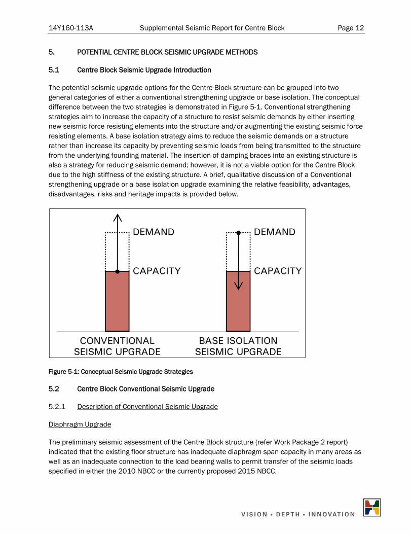
The potential seismic upgrade options for the Centre Block structure can be grouped into two general categories of either a conventional strengthening upgrade or base isolation. The conceptual difference between the two strategies is demonstrated in Figure 5-1. Conventional strengthening strategies aim to increase the capacity of a structure to resist seismic demands by either inserting new seismic force resisting elements into the structure and/or augmenting the existing seismic force resisting elements. A base isolation strategy aims to reduce the seismic demands on a structure rather than increase its capacity by preventing seismic loads from being transmitted to the structure from the underlying founding material. The insertion of damping braces into an existing structure is also a strategy for reducing seismic demand; however, it is not a viable option for the Centre Block due to the high stiffness of the existing structure. A brief, qualitative discussion of a Conventional strengthening upgrade or a base isolation upgrade examining the relative feasibility, advantages, disadvantages, risks and heritage impacts is provided below.
Figure 5-1: Conceptual Seismic Upgrade Strategies
5.2 Centre Block Conventional Seismic Upgrade
5.2.1 Description of Conventional Seismic Upgrade
Diaphragm Upgrade
The preliminary seismic assessment of the Centre Block structure (refer Work Package 2 report) indicated that the existing floor structure has inadequate diaphragm span capacity in many areas as well as an inadequate connection to the load bearing walls to permit transfer of the seismic loads specified in either the 2010 NBCC or the currently proposed 2015 NBCC.
14Y160-113A Supplemental Seismic Report for Centre Block Page 13
An upgrade of the diaphragm to either the 2010 or 2015 NBCC could potentially involve the following steps:
1) Remove non-loading bearing partitions and floor finishes (or roofing);
2) Removing existing topping to expose tops of steel floor beams;
3) Weld studs to tops of steel beams;
4) In areas where diaphragm loads are concentrated due to openings, weld plate bracing to the tops of the steel beams to provide additional strength;
5) Weld continuous bent plates to tops of steel beams along wall perimeters;
6) Connect bent plates to walls with rods anchors drilled into walls;
7) Replace topping with reinforced concrete topping; and
8) Reinstate floor finish and non-load bearing partitions.
Wall Upgrade
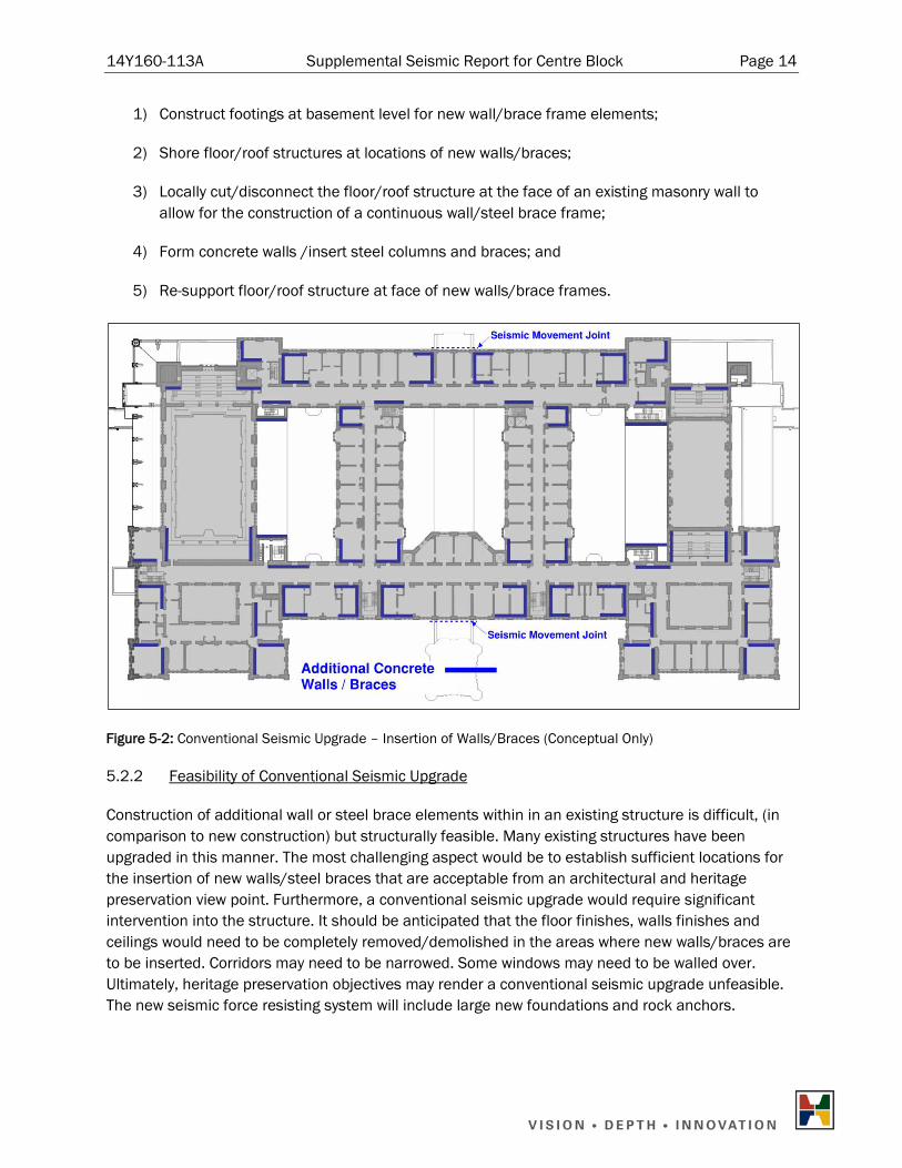
The preliminary seismic assessment of the Centre Block structure also determined that a number of the existing masonry walls have inadequate capacity to resist 2010 NBCC or proposed 2015 NBCC seismic loads. A conventional seismic upgrade scheme to increase the lateral load capacity of the structure could consist of the insertion at discreet locations of either additional concrete walls or structural steel bracing. An indicative plan layout of additional concrete wall/steel brace elements (for conceptual purposes only) is shown in Figure 5-2 based on the 2010 NBCC. The lower loads proposed in the current draft version of the 2015 NBCC may reduce the amount of reinforcing in the concrete walls or reduce the size of the steel brace elements but would not drastically change the overall seismic upgrade scheme.
The intent of Figure 5-2 is to highlight that a significant number of additional wall or brace locations may be required due to the limitations of the diaphragms and the existing architectural form. Even after the completion of work to upgrade the floor and roof diaphragms, each floor plate would still consist of a collection of individual diaphragms that span between the closest load bearing walls only, due to the lack of continuity of the floor structure through the load bearing masonry walls. The large clear spaces (The House of Commons, the two Caucus rooms, the Hall of Honour, and the Senate Chamber) further fragment the floor plate. Subsequently, additional walls/braces may be required at many locations.
It is envisioned that the new concrete walls or steel brace frames could occupy a similar plane of space on the face of the existing masonry walls and will subsequently have a similar architectural impact. The interaction with the existing structure, feasibility, advantages, disadvantages, risks and heritage impact will also be similar.
Insertion of new concrete walls or steel braces would involve the following steps:
14Y160-113A Supplemental Seismic Report for Centre Block Page 14
1) Construct footings at basement level for new wall/brace frame elements;
2) Shore floor/roof structures at locations of new walls/braces;
3) Locally cut/disconnect the floor/roof structure at the face of an existing masonry wall to allow for the construction of a continuous wall/steel brace frame;
4) Form concrete walls /insert steel columns and braces; and
5) Re-support floor/roof structure at face of new walls/brace frames.
Figure 5-2: Conventional Seismic Upgrade – Insertion of Walls/Braces (Conceptual Only)
5.2.2 Feasibility of Conventional Seismic Upgrade
Construction of additional wall or steel brace elements within in an existing structure is difficult, (in comparison to new construction) but structurally feasible. Many existing structures have been upgraded in this manner. The most challenging aspect would be to establish sufficient locations for the insertion of new walls/steel braces that are acceptable from an architectural and heritage preservation view point. Furthermore, a conventional seismic upgrade would require significant intervention into the structure. It should be anticipated that the floor finishes, walls finishes and ceilings would need to be completely removed/demolished in the areas where new walls/braces are to be inserted. Corridors may need to be narrowed. Some windows may need to be walled over. Ultimately, heritage preservation objectives may render a conventional seismic upgrade unfeasible. The new seismic force resisting system will include large new foundations and rock anchors.
14Y160-113A Supplemental Seismic Report for Centre Block Page 15
5.2.3 Advantages of a Conventional Seismic Upgrade
The advantages of a conventional construction seismic upgrade option for the Centre Block are as follows:
a) The addition of walls or steel braces to an existing structure is a relatively common seismic upgrade project. Many local engineering consultants and contractors have familiarity with strengthening projects using conventional techniques, although not necessarily in a building like the Centre Block;
b) Addition of walls or steel braces will add strength to the structure;
c) Occupant safety will be increased through a greater degree of protection against collapse in a seismic event; and
d) Relatively small seismic movement joints between the Centre Block and Peace Tower and the Centre Block and the Parliamentary Library will be required, based on the stiffness of the new walls or braces.
5.2.4 Disadvantages of a Conventional Seismic Upgrade
The disadvantages of a conventional construction seismic upgrade option for the Centre Block are as follows:
a) Although many of the existing masonry walls have inadequate strength, they still possess a high degree of stiffness. Newly added concrete walls/steel braces will only begin to resist seismic loads once the existing masonry walls have accumulated sufficient damage to degrade their stiffness. Adding new concrete walls/steel brace elements, therefore, provides residual strength to guard against collapse but does not necessarily protect the original masonry wall structure from damage. Significant damage to the structure’s masonry walls in a design earthquake event would still be anticipated;
b) Continued occupancy in the post-earthquake period may not be possible;
c) The post design earthquake repair cost could be significant;
d) Insertion of new structural elements (walls or braces) will require significant intervention into the structure. In the locations of the new walls/braces, all floor finishes, walls finishes, and ceilings will likely have to be removed. This may not be acceptable from a heritage preservation view point; and
e) Non-structural components will still require case by case remediation.
5.2.5 Risks of a Conventional Seismic Upgrade
A conventional seismic upgrade scheme based on the insertion of new concrete walls or steel braces will have a high magnitude of interaction with the existing structure, of which, only an incomplete
14Y160-113A Supplemental Seismic Report for Centre Block Page 16
knowledge is possible. The existing structural drawings present the basic framing system information, but provide relatively limited detail section information. As with most buildings, much of the structure is concealed within ceiling spaces, wall spaces and behind finishes. Compounding the lack of detail information is the relatively complex architectural form and varying structural configurations across the building. It is probable that many unique structural conditions currently exist across the building. It would not be unreasonable to assume that numerous unforeseen and potentially problematic structural conditions may be discovered upon removal of finishes and non-structural components. This could present a risk of an increased project timeline and cost.
5.2.6 Heritage Impact of a Conventional Seismic Upgrade
The heritage impacts of a conventional construction seismic upgrade option for the Centre Block are as follows:
a) As noted above, a conventional seismic upgrade scheme based on the insertion of new concrete walls or steel braces will require a high magnitude of intervention into the existing structure. The new walls or steel braces could potentially be hidden behind architectural finishes in the final condition; however a large amount of the existing finishes would need to be removed to implement their installation. It should be anticipated that, in the areas around where the new walls/brace frames are to be inserted, all existing wall finishes, floor finishes, and ceilings will need to be completely removed; and
b) A seismic movement gap, in the order of 25mm–50mm, between the Centre Block and the Parliamentary Library and the Centre Block and the Peace Tower may be required to prevent the individual structures from pounding on each other during seismic shaking. Providing seismic movement gaps between adjacent structures to prevent this possibility is required by the NBCC and is considered the standard of best practice. It may be possible to forego the seismic movement gaps if a detailed study of the areas demonstrated that the level of expected damage was low and that the probability of localized collapse is unlikely. If seismic movement gaps between the Centre Block and adjoining structures are implemented, they would involve the creation of vertical slots through the existing masonry and installation of flexible joint products. It may be possible to visually disguise the joints with a sacrificial stonework covering.
5.3 Centre Block Base Isolation Seismic Upgrade
5.3.1 Description of a Base Isolation Seismic Upgrade
Base isolation, as a strategy for seismic protection, seeks to reduce the level of seismic demand on a structure via the insertion of a system of “springs” between the structure and its foundation. The high flexibility of the base isolator springs, relative to the supported structure above, limits the intensity of seismic shaking that can be transmitted to the structure.
For base isolation to be effective, it is necessary to ensure that the only points of contact between the structure and its foundation occur at the isolators and that the structure has unrestrained freedom to displace laterally when subjected to seismic loading.
14Y160-113A Supplemental Seismic Report for Centre Block Page 17
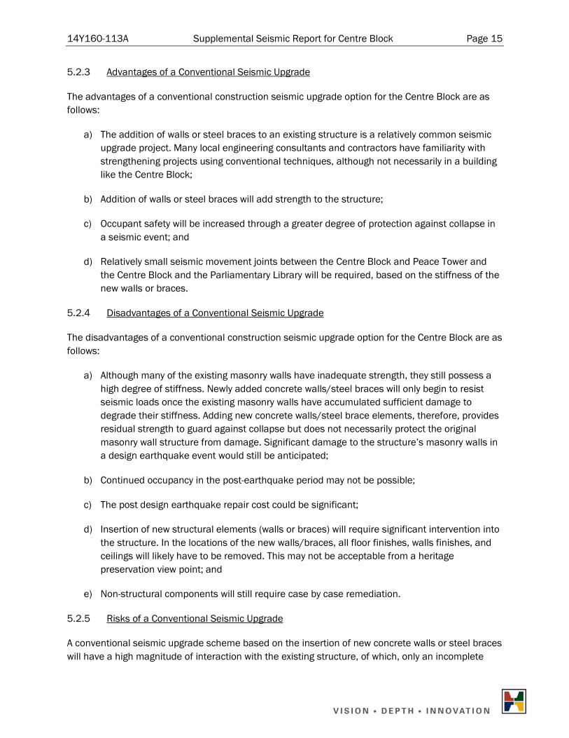
The isolation plane can be located at the base of a structure, between the footings and the founding material. Alternatively, for structures with a basement level, the isolation plane can be located somewhere above the base of the structure e.g. at the underside of the ground floor level. An example of this application is shown in Figure 5-3.
Figure 5-3: Example of seismic isolators at underside of a ground floor slab
(Image supplied by Ausenco Canada Inc.)
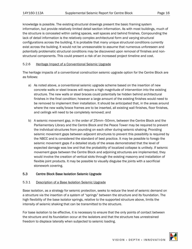
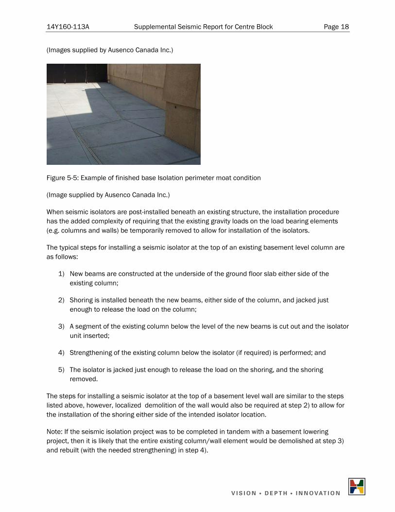
For structures with the isolation plane located below grade, this typically requires a “moat” to be constructed around the building to allow for the lateral displacement of the isolators. Figure 5-4 provides an example of a base isolation moat in the process of being constructed around a base isolated building. The finished condition, with the moat covered and concealed is shown in Figure 5-5.
Perimeter Moat Example Perimeter Moat Cover Example
Figure 5-4: Example of Base Isolation Perimeter Moat Construction
14Y160-113A Supplemental Seismic Report for Centre Block Page 18
(Images supplied by Ausenco Canada Inc.)
Figure 5-5: Example of finished base Isolation perimeter moat condition
(Image supplied by Ausenco Canada Inc.)
When seismic isolators are post-installed beneath an existing structure, the installation procedure has the added complexity of requiring that the existing gravity loads on the load bearing elements (e.g. columns and walls) be temporarily removed to allow for installation of the isolators.
The typical steps for installing a seismic isolator at the top of an existing basement level column are as follows:
1) New beams are constructed at the underside of the ground floor slab either side of the existing column;
2) Shoring is installed beneath the new beams, either side of the column, and jacked just enough to release the load on the column;
3) A segment of the existing column below the level of the new beams is cut out and the isolator unit inserted;
4) Strengthening of the existing column below the isolator (if required) is performed; and
5) The isolator is jacked just enough to release the load on the shoring, and the shoring removed.
The steps for installing a seismic isolator at the top of a basement level wall are similar to the steps listed above, however, localized demolition of the wall would also be required at step 2) to allow for the installation of the shoring either side of the intended isolator location.
Note: If the seismic isolation project was to be completed in tandem with a basement lowering project, then it is likely that the entire existing column/wall element would be demolished at step 3) and rebuilt (with the needed strengthening) in step 4).
14Y160-113A Supplemental Seismic Report for Centre Block Page 19
Installation of the isolators in different areas of the basement can be sequenced as best suits the construction process.
Diaphragm Upgrade
As noted in the Conventional Seismic Upgrade description, the preliminary seismic assessment of the Centre Block found that the existing floor structure is typically inadequate to act as a structural diaphragm and has inadequate connection to the load bearing walls. Implementation of seismic isolation in the basement level of the Centre Block would significantly reduce the seismic demands imposed on the floor diaphragms; however, some diaphragm upgrade work similar to that described in the Conventional Seismic Upgrade description would still be required. At the very least, the connection of the floor diaphragms to the walls would still require upgrading to meet 2010 or 2015 NBCC requirements. This would require localized removal of the existing topping adjacent to the inadequately connected walls or diaphragm discontinuities and the installation of bent plates and rod anchors as described in steps 5) to 8) of Section 5.2.1.
5.3.2 Feasibility of a Base Isolation Seismic Upgrade
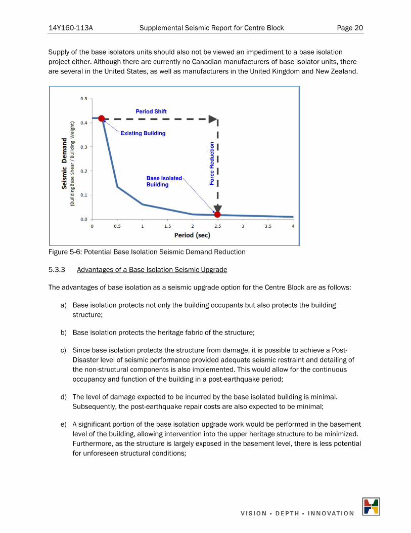
Base Isolation of the Centre Block structure is a feasible method of seismic upgrade. Base isolation is ideally suited to low rise, heavy, rigid structures. The historic masonry construction of the Centre Block building has exactly these characteristics. The potential reduction in seismic demand that could be achieved by base isolation is illustrated in Figure 5-6. As shown in the figure, the current fundamental period of vibration of the Centre Block building is very short; a result of the high degree of stiffness of the existing building. Subsequently, the building in its existing state will attract a high level of seismic demand. By insertion of base isolators beneath the building, the fundamental period of the structure is shifted to a longer value, causing the effective stiffness of the building to be softened and the seismic demand reduced.
The high level of protection that seismic isolation provides is also ideally suited to structures with a high heritage value, where the desired objective is to not only prevent collapse but to preserve the heritage fabric of the structure as well. The Centre Block could be considered to fall within this category.
Although base isolation seismic upgrade projects are historically rare in Canada, installation of base isolators beneath existing heritage masonry structures has been performed at many locations around the world. Some summaries of these projects have been documented in the Work Package 1 Report. The lack of local engineering experience in base isolation design should not be viewed as a particular impediment. A substantial portion of the engineering work involved in a base isolation project, e.g. the design of new load bearing beams in the basement to enable shoring and jacking of the structure etc., is relatively uncomplicated. The main concern is to ensure that the jacking operations are performed with sufficient care such that accidental damage to the upper structure is avoided. Assistance with the design and sizing of the base isolators units can be provided by specialist sub-consultants.
14Y160-113A Supplemental Seismic Report for Centre Block Page 20
Supply of the base isolators units should also not be viewed an impediment to a base isolation project either. Although there are currently no Canadian manufacturers of base isolator units, there are several in the United States, as well as manufacturers in the United Kingdom and New Zealand.
Figure 5-6: Potential Base Isolation Seismic Demand Reduction
5.3.3 Advantages of a Base Isolation Seismic Upgrade
The advantages of base isolation as a seismic upgrade option for the Centre Block are as follows:
a) Base isolation protects not only the building occupants but also protects the building structure;
b) Base isolation protects the heritage fabric of the structure;
c) Since base isolation protects the structure from damage, it is possible to achieve a Post-Disaster level of seismic performance provided adequate seismic restraint and detailing of the non-structural components is also implemented. This would allow for the continuous occupancy and function of the building in a post-earthquake period;
d) The level of damage expected to be incurred by the base isolated building is minimal. Subsequently, the post-earthquake repair costs are also expected to be minimal;
e) A significant portion of the base isolation upgrade work would be performed in the basement level of the building, allowing intervention into the upper heritage structure to be minimized. Furthermore, as the structure is largely exposed in the basement level, there is less potential for unforeseen structural conditions;
14Y160-113A Supplemental Seismic Report for Centre Block Page 21
f) A base isolation upgrade would complement a basement lowering project, as the shoring and jacking work required to temporarily relieve the load on existing columns would be common to both projects;
g) Base isolation provides protection to non-structural components; and
h) Further investigations/studies into the exact material properties of the existing masonry walls are less likely to be required.
5.3.4 Disadvantages of a Base Isolation Seismic Upgrade
The disadvantages of base isolation as a seismic upgrade option for the Centre Block are as follows:
a) If seismic isolators are installed beneath the Centre Block building, then a large seismic movement gap will be required to allow freedom of movement at the isolation plane. As described above, this would necessitate the construction of a “moat” around the perimeter of the building;
b) A large movement gap (100mm-150mm) would also be required between the Centre Block and adjoining structures. This would involve the creation of a vertical slot through the existing masonry and installation of a flexible joint product. It may be possible to visually disguise the joint with a sacrificial stonework covering; and
c) If post-disaster occupancy and function of the building is desired, any mechanical services (ducts, pipes, wiring etc.) that pass from the basement level to the upper structure must have flexible connections installed at the isolation plane to accommodate the large expected lateral displacement (100mm-150mm) of the isolators. Care also needs to be taken to ensure that any stairs and elevators that travel down into the basement level are disconnected from the basement structure and are detailed to accommodate the potential isolator movement.
5.3.5 Risks of Base Isolation Seismic Upgrade
The risks of base isolation as a seismic upgrade option for the Centre Block are as follows:
a) The installation of base isolators beneath an existing structure requires extensive jacking and shoring to temporary relieve the gravity load on the existing columns and walls. The jacking operations need to be performed with considerable care to prevent accidentally incurring damage (cracking) in the upper structure. However, this risk can be minimized through careful monitoring and planning; and
b) There are potentially less consultant engineers and contractors who possess the specialized expertise required for the design and implementation a base isolation seismic upgrade than compared with a conventional seismic upgrade scheme.

14Y160-113A Supplemental Seismic Report for Centre Block Page 22
5.3.6 Heritage Impact of a Base Isolation Seismic Upgrade
As noted above, if seismic isolators are installed beneath the Centre Block then a relatively large movement gap would be required between the Centre Block and adjoining structures. This could be in the range of 100mm–150mm. Currently the Centre Block adjoins the Parliamentary Library on the north side of the building and the Peace Tower on the south side. It may be possible to support the Peace Tower on the same system of isolators as the Centre Block, in which case only a small seismic movement joint between the two structures may be required. As per the discussion in section 5.2.6, it may be possible to forego the expansion gap between the Peace Tower and Centre Block if a detailed study of the area indicated that the level of expected damage is low. For further discussion regarding base isolation of the Peace Tower, see Section 6.3. It should be noted that creation of a seismic movement joint between the Centre Block and adjoining structures would also be required in a conventional seismic upgrade scheme, however, the size of movement joint would be considerably smaller (25 - 50mm etc.) with a correspondingly smaller heritage impact.
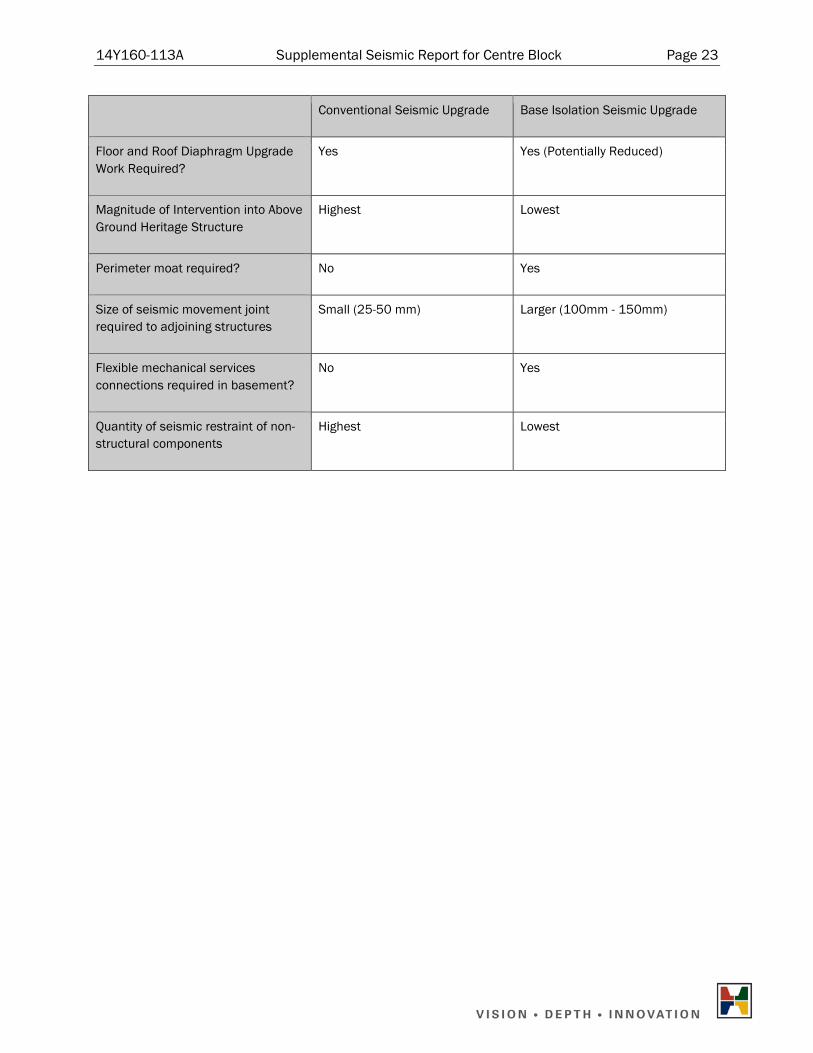
5.4 Comparison of Conventional Seismic Upgrade versus Base Isolation for the Centre Block
A summary of the discussion presented above for a conventional seismic upgrade and a base isolation seismic upgrade is tabulated below.
Table 5-1: Seismic Upgrade Option Comparison for the Centre Block
Conventional Seismic Upgrade Base Isolation Seismic Upgrade
Collapse Resistance Increased? Yes Yes
Occupant Life Safety Protection Increased?
Yes Yes
Existing Masonry Structure Protected?
Limited/Partial Yes
Level of Expected Design Earthquake Damage to Structure?
High Minimal
Post-Disaster Occupancy Possible? Unlikely Yes
Magnitude of Post Design Earthquake Repair Cost
High Minimal
Heritage Finishes Protected? No Yes
14Y160-113A Supplemental Seismic Report for Centre Block Page 23
Conventional Seismic Upgrade Base Isolation Seismic Upgrade
Floor and Roof Diaphragm Upgrade Work Required?
Yes Yes (Potentially Reduced)
Magnitude of Intervention into Above Ground Heritage Structure
Highest Lowest
Perimeter moat required? No Yes
Size of seismic movement joint required to adjoining structures
Small (25-50 mm) Larger (100mm - 150mm)
Flexible mechanical services connections required in basement?
No Yes
Quantity of seismic restraint of non-structural components
Highest Lowest
14Y160-113A Supplemental Seismic Report for Centre Block Page 24
6. POTENTIAL PEACE TOWER SEISMIC UPGRADE METHODS
6.1 Peace Tower Seismic Upgrade Introduction
The preliminary seismic assessment of the Peace Tower structure (refer to Work Package 2 report) identified several components of the structure that were unable to resist either 100% of the 2010 NBCC or proposed 2015 draft NBCC seismic loads. As discussed in section 5.1, seismic retrofit methods can be generally divided into two categories, conventional seismic upgrades and base isolation. A brief, qualitative discussion of the two strategies examining the relative feasibility, advantages, disadvantages, risks and heritage impact follows.
It is important to note that decisions to seismically upgrade either the Centre Block main building or Peace Tower should not be made in isolation from each other.
Due their attachment and proximity, collapse or damage of one structure from a seismic event, may, in the worst case, cause collapse of the other structure, or at best, cause the other structure to be unable to be occupied, regardless of the other structure’s level of seismic upgrade.
6.2 Peace Tower Conventional Seismic Upgrades
The seismic force resisting system of the main portion of the Peace Tower below the Observation Deck level is concrete and stone masonry walls, punctuated by several large openings, which define the wall piers and spandrel beams. As identified in the preliminary seismic analysis, several of the piers and spandrel beams have inadequate capacity to resist either the 2010 NBCC or the proposed 2015 NBCC seismic loads. A conventional seismic upgrade for the Peace Tower could be achieved by reinforcing local elements rather than introducing a new structural system such as a steel braced frame. For the lower seismic loads that would be imposed on the Peace Tower by the proposed 2015 NBCC, the same types of reinforcing would be required but on a reduced scope.
There are three locations where the spandrel beams had inadequate capacity to resist the seismic loads: at the keyboard room level, at the Memorial Chamber ceiling on the South, East and West faces and above the Porte Cochere on the North face.
In addition, the corners piers between the refuge floor and the keyboard room level on the South face, and the corner piers between the Memorial Chamber floor and the keyboard room level on the North face have inadequate capacity. Seismic retrofit for the piers and spandrels are discussed below.
6.2.1 Spandrel Beam Upgrade Methods
The spandrel beams at the various levels are typically composed of either unreinforced concrete and stone masonry, which arches over the opening below, or steel beams encased in the concrete that span to the corner piers. In both instances, the spandrel beams with inadequate capacity will need to be reinforced for both shear and flexure.
14Y160-113A Supplemental Seismic Report for Centre Block Page 25
One option to upgrade these spandrel beams is to install drilled steel anchors both vertically and horizontally through the concrete and stone to add both flexural and shear capacity. It is anticipated that this work would be completed from the exterior of the tower.
A second option would be to install fibre reinforced polymer (FRP) fabrics on the interior face of the spandrel beam, with FRP anchors into the corner piers. It is anticipated that this work would be completed from the interior and that certain interior components would need to be removed and reinstated to complete the work.
A third option would involve temporarily shoring the structure above, removing the existing spandrel, replacing it with a reinforced concrete or steel beam spandrel and recreating a stone façade. This process would be similar to the work that was completed on the North face of the Peace Tower for the inclined elevator addition.
6.2.2 Pier Upgrade Methods
The piers in each corner of the Peace Tower are composed of unreinforced concrete with an outer wythe of stone masonry. The typical failure mechanism of the piers is rocking.
An effective means of increasing the rocking capacity of the piers is to increase the axial load on them by installing post-tensioned anchors. One method to install the anchors would be to remove the turrets at the observation deck level and drill the anchors down into the piers. The turrets can then be reinstated.
An alternative method of installing the anchors would be to remove a line of the stone masonry up each side of the piers and chip back into the concrete. The anchor can then be set in the recess, tensioned and grouted in place. Afterwards, the stone masonry is reinstated.
There are also several smaller, slender masonry piers with minor spandrel beams in the middle of each face that frame smaller openings to the bell chambers and other interior spaces above the refuge level. These piers were determined to begin rocking under low seismic loads and do not contribute significantly the seismic force resisting system. However, they should be restrained and anchored to the rest of the structure from the interior with structural steel elements to prevent them from collapsing over top of one of the main exits to the Centre Block.
6.2.3 Upper Tower Upgrade Methods
The Upper Tower portion of the Peace Tower can be defined as the structure above the Observation Deck level, and has three main components: the observation deck, the clock face and the sloped roof. As identified in Work Package 2, each of the components of the Upper Tower has inadequate capacity to resist the 2010 NBCC seismic loads. In addition, there is no well-defined load path between the components.
All of the components could be reinforced using any or all of the methods described above for the spandrel beams and piers, including: drilled steel anchors, FRP fabrics, or new steel or reinforced concrete members.

14Y160-113A Supplemental Seismic Report for Centre Block Page 26
6.2.4 Peace Tower Conventional Seismic Upgrade Feasibility
The conventional seismic upgrade options described above are generally well understood within Ottawa’s construction industry and should be feasible to build.
Drilled anchors are currently being used to reinforce the Ventilation Towers on the back of the Centre Block. FRP fabrics have been used on numerous masonry rehabilitation projects, and replacing the spandrel beam would be a similar process to what was completed on the North face in the early 1980’s.
6.2.5 Advantages of a Peace Tower Conventional Seismic Upgrade
The advantages of conventional construction seismic upgrade options for the Peace Tower are as follows:
a) The installation of drilled anchors, FRP fabrics or steel or reinforced concrete members are well understood within the consulting and construction industries. These experiences should reduce the frequency and size of unanticipated changes occurring during construction;
b) Conventional seismic retrofit methods increase the occupant safety of the structure by providing additional strength to prevent collapse;
c) The primary advantage of the drilled anchors is that it requires limited or no deconstruction of part of the existing tower;
d) For the FRP fabrics strengthening, the main advantage is that the majority of the work would be completed from the interior, so there is less chance of damaging the exterior stone work; and
e) Replacing the existing spandrels has the advantage of giving the most strengthening potential because it is not limited by the existing spandrels dimensions and strengths.
6.2.6 Disadvantages of a Peace Tower Conventional Seismic Upgrade
The disadvantages of conventional construction seismic upgrade options for the Peace Tower are as follows:
a) A conventional seismic retrofit will not prevent damage to piers and spandrel beams, as well as secondary structural elements, which would be likely in the event of a significant earthquake. This damage could take the form of localized crushing of the concrete and masonry, extensive cracking and yielding of steel elements, and significant displacement of the structure;
b) Occupancy of the Peace Tower may not be possible after a seismic event if the magnitude of damage to the Peace Tower is significant. Additionally, even if the Centre Block is undamaged, damage to the Peace Tower could prevent occupancy of the Centre Block as there may be risk of the Peace Tower collapsing during an aftershock;
c) The main disadvantage of drilled anchors is that they require drilling from the exterior of the building, which may require significant scaffolding to access the drilling locations, and vibrations, pressure or water damage could occur from the drilling process;

14Y160-113A Supplemental Seismic Report for Centre Block Page 27
d) The main disadvantage of using FRP strengthening is that working from the interior would mean temporarily removing and replacing existing components on the inside of the structure, such as floor structures, bell structures or elevator equipment; and
e) Replacing the existing spandrels is the most intrusive to the existing structure and would have the greatest likelihood of damage occurring to the tower during construction.
6.2.7 Peace Tower Conventional Seismic Upgrade Risks
The risks of the conventional seismic upgrade options for the Peace Tower include:
a) In all of the conventional seismic upgrade options, there is a risk of damaging the existing structure during construction. Drilling anchors, or removing and reinstating components of the tower, are very intrusive activities that even with careful diligence may damage existing materials, especially if they have deteriorated in any way; and
b) As with all existing structures, a complete understanding of all of the details of the as-built structure cannot be known. Consequently, there is a risk of discovering unforeseen conditions or deterioration that can impact schedule and cost of the retrofit.
6.2.8 Peace Tower Conventional Seismic Upgrade Heritage Impacts
All of the conventional seismic upgrade options would have very limited intended impact on the exterior appearance of the Peace Tower because the work can generally be complete within the concrete walls, or from the interior of the structure. However, the heritage impacts of the conventional seismic upgrade options for the Peace Tower include:
a) The installation of the conventional seismic upgrade methods could have unintended heritage impact if the installation process accidentally damages the exterior stone work, sculptures or Memorial Chamber; and
b) A seismic gap (25 - 50 mm) between the Peace Tower and the Centre Block could require a visual change to the interior and exterior of the structure wherever it is introduced unless covered by a sacrificial stone covering. Refer to section 5.2.6 for further discussion.
6.3 Peace Tower Base Isolation Seismic Upgrades
As described in section 5.3, the main purpose of base isolation is to reduce the seismic demand on the structure rather than increasing its strength. In some instances, strengthening work may still be required, although typically to a lesser degree.
6.3.1 Peace Tower Base Isolation Method
The process for base isolating the Peace Tower would be similar to that described for the Centre Block. A new diaphragm would need to be constructed immediately above the isolator plane to rigidly tie the four massive piers of the Peace Tower together. Following that, small portions of the piers would be removed, one at a time, and the base isolators inserted. The base isolator is jacked just enough to distribute a set amount of load onto the isolator, and the process is repeated for multiple isolators under each pier. As with the Centre Block, a moat is required around the structure to allow lateral displacement.
14Y160-113A Supplemental Seismic Report for Centre Block Page 28
It is not ideal to base isolate the Peace Tower by itself because the estimated wind base shear on the Peace Tower is greater than the estimated isolated base shear (because it has less mass per exterior surface area than the Centre Block). The isolators would need to be much stiffer to resist the wind load, which does not allow the full benefit of base isolation to be realized.
A seismic gap would be required between the Peace Tower and the Centre Block but its size is dependent on the configuration of the base isolation. If only the Centre Block is base isolated, a large gap would be required between the two structures, either with a moveable joint or sacrificial covering that is designed to break away in the event of an earthquake.
If the Peace Tower and Centre Block are isolated and rigidly connected together beneath the ground floor level, a small seismic gap, similar to what would be required for a conventional upgrade (25 – 50 mm), would still be required above the isolation plane. The isolation would reduce the movements but the two structures would still want to move independently from each other.
While base isolation would significantly reduce the loads on the Peace Tower, the Upper Tower upgrades, as discussed in section 6.2.3, will still be required to address elements with extremely low capacity/demand ratios and to establish complete load paths that do currently exist. Past experiences have also shown that yielding of the lead core in the base isolators can excite the higher modes of tall slender components, such as the Upper Tower. The results are not reflected in linear modal response analysis but can be more accurately determined using non-linear time history analysis.
6.3.2 Peace Tower Base Isolation Feasibility
Base isolation has been successfully retrofitted into many masonry structures, including those with large towers, and is a feasible seismic upgrade option for the Peace Tower. Although the greatest advantage is leveraged for very stiff structures, there is still significant opportunity to reduce the loads to approximately 75% of the un-isolated loads.
Base isolation is relatively new to Canada and only a few base isolation projects are currently underway. As previously discussed, design of the base isolated system would be improved through the experience of a specialist consultant with experience with these systems.
6.3.3 Advantages of a Peace Tower Base Isolation Seismic Upgrade
The advantages of base isolating the Peace Tower are similar to those discussed for the Centre Block, including as follows:
a) Base isolation provides a higher level of protection to the structure, its components and occupants than conventional reinforcing methods; and
b) The risk of damage that exists with drilling and cutting for conventional retrofit methods is reduced for base isolation.
14Y160-113A Supplemental Seismic Report for Centre Block Page 29
6.3.4 Disadvantages of a Peace Tower Base Isolation Seismic Upgrade
The disadvantages of base isolating the Peace Tower are similar to those discussed for the Centre Block, including as follows:
a) The shoring and jacking procedure for the much more heavily loaded foundations of the Peace Tower could pose additional challenge and risk than a typical base isolation project; and
b) A small seismic gap is required around the Peace Tower, which may impact the heritage finishes where the Peace Tower links to the Centre Block.
6.3.5 Peace Tower Base Isolation Risks
The risks of base isolation as a seismic upgrade option for the Peace Tower include:
a) The installation of base isolators beneath an existing structure requires extensive jacking and shoring to temporarily relieve the gravity load on the existing columns and walls. The jacking operations need to be performed with considerable care to prevent accidentally incurring damage (typically cracking) in the upper structure. In typical masonry wall structures, gravity loads may redistribute without extensive cracking if settlement occurs at one location. However, the settlement risk is increased for the Peace Tower because there are no alternative gravity load paths for the tower and even small settlements could create cracking or stability issues. However, this risk can be minimized through careful monitoring and planning; and
b) There are potentially less consultant engineers and contractors who possess the specialized expertise required for the design and implementation a base isolation seismic upgrade than compared with a conventional seismic upgrade scheme.
6.3.6 Peace Tower Base Isolation Heritage Impact
Most of the base isolation work would take place at the level of the Peace Tower foundations (at the underside of the Centre Block’s ground floor) so the impact on the heritage features would be limited. However, as previously discussed, there can still be a seismic gap required between the Peace Tower and the Centre Block, which may impact both the interior and exterior appearance at the link. A sacrificial seismic joint could be constructed to limit the visual heritage impact.
6.4 Comparison of Conventional Seismic Upgrade versus Base Isolation for the Peace Tower
A summary of the discussion presented above for a conventional seismic upgrade and a base isolation seismic upgrade is tabulated below.

14Y160-113A Supplemental Seismic Report for Centre Block Page 30
Table 6-1: Seismic Upgrade Option Comparison for the Peace Tower
Conventional Seismic Upgrade Base Isolation Seismic Upgrade
Collapse Resistance Increased? Yes Yes
Occupant Life Safety Protection Increased?
Yes Yes
Existing Masonry Structure Protected?
Limited/Partial Yes
Level of Expected Design Earthquake Damage to Structure?
High Minimal
Post-Disaster Occupancy Possible? Unlikely Yes
Magnitude of Post Design Earthquake Repair Cost
High Minimal
Heritage Finishes Protected? No Yes
Magnitude of Intervention into Above Ground Heritage Structure
Moderate Lowest
Perimeter moat required? No Yes
Size of seismic movement joint required to adjoining structures
Small (25-50 mm) Small (25-50 mm) if isolated with the Centre Block
Quantity of seismic restraint of non-structural components
Highest Lowest
14Y160-113A Supplemental Seismic Report for Centre Block Page 31
7. SEISMIC RETROFIT OF OPERATIONAL AND FUNCTIONAL COMPONENTS An assessment of the requirements to provide seismic restraint to the operational and functional components (OFCs) in the Centre Block will be described in this section of the report. For the Centre Block, the focus will be on historic architectural features, including chimneys, suspended ceilings, and light fixtures, which should be seismically restrained to prevent damage. For other features, restraint will be required for items that may impact a historic feature or for other items that require restraint at a Normal Importance level.
A full list of OFCs observed in the Centre Block and Peace Tower and their current connections to the structure is described in Work Package 2. Only the OFCs that are currently installed and are not exempt from the seismic restraint requirements are included in this report. As indicated by PWGSC, all mechanical and electrical equipment (including ventilation, water distribution, and elevator systems) will be removed for the renovations to the building, and are not included in this review. Other OFCs that will be installed during the renovations will also require restraint, including items that are removed and reinstated. Any items described in this report that are removed during the rehabilitation will not need seismic restraint.
7.1 Typical Restraint Methods
Typical types of restraint for the various types of connections observed in the Centre Block will be described in this section of the report, along with potential difficulties for the installation of the types of restraint. Preservation of the architectural features has been highlighted as a priority for the upgrades, so methods of minimizing the destructive openings required or the visual impact of restraint will be discussed where possible.
7.1.1 Suspended equipment
A large portion of the interior items which require seismic restraint in the Centre Block are suspended, including ceilings and light fixtures. Typical restraint for suspended items involves installing angled cables or braces in all four corners. Struts could be used to provide restraint instead of cables, and would require fewer struts in each direction, but the adjustability of cable restraints would recommend them based on the existing conditions. If a rod is providing the gravity support, stiffener clamps would be required along the length of the rod to prevent buckling,. If a cable is providing gravity load support, the braces should be designed for the seismic load in addition to the weight of the suspended object. For items like suspended ceilings, which have many gravity supports spaced in both directions, they are restrained in a similar manner to discrete suspended objects, with a grid of cables or braces in both directions provided at a spacing governed by the magnitude of the seismic load. A gap between the walls and the edge of the ceiling is recommended to allow for some deflection of the ceiling without damage from impacting a wall.
7.1.2 Wall-mounted equipment Lightweight items which are mounted on the wall are exempt from seismic restraint requirements. Heavy artwork or stone features might require restraint, which is frequently similar to gravity loads but with larger diameter anchors than those required for gravity loads. Connection details may be complicated by the connection into stone walls, as not all connectors are seismically rated or applicable for stone masonry, and the anchors may break the exterior side of the stone and cause a visible mark. Large items may require

14Y160-113A Supplemental Seismic Report for Centre Block Page 32
connection to a steel member through the wall or the construction of a supporting frame which is cantilevered above the floor slab.
7.1.3 Base-mounted equipment There are stone and metal statues on stone bases in addition to mechanical or electrical equipment that may remain. Base-mounted equipment is typically connected to the concrete slab or steel deck below, and cannot be connected to the concrete topping or housekeeping slab. For statues on the stone bases, it would be required that the statue be connected to the base and also that the base be connected to the floor structure. Tall cupboards should be connected to the floor and to the wall to prevent overturning under seismic loads.
7.1.4 Partition walls
Partition walls are typically restrained by providing some form of connection to the structure above. A frequent type of restraint is a steel angle on each side of the wall, connected to the underside of the beam above. A deflection gap based on the anticipated displacement of the structure should be provided at the top of the wall.
The wall must also be capable of withstanding the required out of plane loads without collapse, so terra cotta brick partition walls and other unreinforced walls may require reinforcement. For walls which cannot be reinforced and grouted, a steel plate or sheet of FRP adhered to one side of the wall can provide sufficient strength.
7.1.5 Exterior Elements
Reinforcement of some exterior elements has been done at Centre Block and the Peace Tower. Similar reinforcement with epoxied steel dowels should be provided for unreinforced exterior elements.
7.2 Description of Items Requiring Restraint
This section will describe the items that will require restraint in the Centre Block, the current connection to the structure, and the type of restraint that would be recommended for each item. Items reviewed in Centre Block include the ceilings, decorative arches, lights, partition walls, cladding, and mechanical and electrical equipment. The main mechanical and electrical systems are being removed, but light fixtures are still included in this report. Very few things were seismically restrained, although many things are exempt.
Items that are exempt from restraint will not be described in this report, but would typically include lightweight wall mounted objects, lightweight suspended objects (such as light fixtures), plaster ceilings, and suspended ceilings in some smaller areas.
14Y160-113A Supplemental Seismic Report for Centre Block Page 33
7.2.1 Terra Cotta Tiles
Structural steel framing members typically have terra cotta tiles surrounding the structural elements as a fireproofing method. The terra cotta tiles used for fireproofing can be a hazard in a seismic event if they separate from the structural element and injure people. The bricks should be reinforced or a method of containment should be provided so that they will not break the plaster ceilings and injure people. This can be a light gauge steel mesh that is wrapped around the underside of the beams and connected to the slab above. The installation of seismic restraint for the terra cotta arches could be coordinated with the openings required for seismic restraint of the plaster ceilings. An alternative could be the removal of the terra cotta tiles, and replacement with an alternative fireproofing method. It has been observed that some tiles have previously fallen from the bottom flanges of the beams, and additional tiles will need to be removed in order to install the connection of seismic restraint of the ceilings and new mechanical services.
7.2.2 Ceilings
None of the ceilings in the Centre Block were observed to be restrained. Both suspended plaster ceilings and lay-in tile suspended ceilings will require restraint. Different ceiling materials may require different approaches in the installation of seismic restraint, due to the ease of access and historical value of the ceilings.
In areas where the ceiling is a drop-in tile on a ceiling suspension system, the restraint can be installed by removing tiles and installing angled cables connecting the ceiling support grid to the slab above. Plaster ceilings require similar restraint, which would require the removal of panels of the plaster ceiling to install restraint above the support frame. Areas with decorative plaster features, such as the ceilings in the Senate Chamber or hallways with suspended stone arches, provide locations where seams in the ceiling could be hidden. The frame supporting the fabric ceiling in the House of Commons chamber requires seismic restraint. As it is not a rigid plaster ceiling, it must be restrained at discrete locations, or else a deflection gap can be provided to allow for the displacement of the entire ceiling. The catwalk just below the HOC chamber ceiling is also built as a frame which is suspended from the girders above, and would require similar restraint. Catwalks, both around the HOC chamber and around some of the skylights could alternatively be connected to the surrounding structure for gravity and seismic loads.
7.2.3 Skylights The skylights are suspended from the beams above, and they should be seismically restrained. Typical restraint of skylights includes providing a gap around the glass so that the movement of the frame in a seismic event does not break the glass, but also ensuring that the opening for the panes of glass are too small so that the glass cannot fall through the openings in the skylight framing. The glass panes could also be positively connected to the frames so that they do not fall out with strong motion. This could be small clips to fit over top of the glass and hold them securely against the frames. Another method of restraining skylights is to provide a film that prevents the glass pieces from separating even after the glass has cracked, so that smaller pieces cannot break off and fall through the

14Y160-113A Supplemental Seismic Report for Centre Block Page 34
openings. Typical warranty periods of the film are ten years, although the interior skylights may have a longer lifespan due to the lack of UV degradation.
7.2.4 Decorative Arches
The arches in the hallways are built on a frame suspended from rods which are designed for only vertical loads, similar to the plaster ceilings, and some are supported together with the ceilings. These arches would be restrained in a similar manner to the suspended plaster ceilings described above.
The arcading, such as in the entrance link to the Memorial Chamber and in the Visitors’ Entrance in the basement, appears to be built solely of stone and are gravity supported without connection to the surrounding structural elements. The arcading in the Senate Entrance Hall has dowels through the columns. The other arcading can be reinforced either by adding dowels inside the stonework to provide adequate connection for the seismic loads, or the upper surface of the arch can be reinforced with an FRP sheet, and additional restraint can be provided for the suspended ceilings between the arches as described above.
7.2.5 Walls Original hollow terra cotta brick partition walls will need seismic restraint. The walls should be restrained from out-of-plane displacement, which is typically done by installing short pieces of steel angles on both sides of the wall at a discrete spacing. The elevator shaft walls should also be restrained, potentially by installing steel plates, FRP sheets, or sprayed concrete on the walls. The reinforcement of the walls should be coordinated with the replacement of the other elevator components. Partial height partition walls also need to be seismically restrained. These walls should be reinforced and connected to the floor slab for the seismic loads. Another method of seismic restraint for these partial height walls could be connecting them to the adjacent structural walls, such as by providing steel channels connected along the top of the wall, that connect to the adjacent walls. If the partition walls are connected to adjacent walls, then it must be confirmed that the adjacent walls have sufficient capacity to resist these additional loads. PWGSC has raised the possibility of renovating the offices inside the Centre Block, possibly to the extent of demolishing and rebuilding partition walls. If terra cotta partition walls are rebuilt during the renovation, then they should be reinforced during construction.
7.2.6 Sculptures
Inside the Centre Block, there are several sculptures on stone bases located throughout the building on the lower levels. Some of the sculptures appeared to be connected to their bases, although the height of the sculptures means that they may be prone to overturning. The weight of the sculpture and the connections between the sculpture and the base and between the base and the structure should be confirmed. A connection to the wall or to a post behind the sculpture from the sculpture itself or the top of the base should be provided to resist overturning as required. The letter chute, which extends the height of the building, may require restraint based on the heritage value of the chute. Since the letter chute is no longer operational, it may be
14Y160-113A Supplemental Seismic Report for Centre Block Page 35
possible to create separations at each floor level between “decorative” sections of the letter chute, with the idea that the smaller sections of the letter chute might be exempt whereas the entire chute would not be exempt. The connections to the wall may require upgrades.
7.2.7 Light fixtures
Light fixtures vary throughout the building, from standard fluorescent lights screwed into the ceiling to elaborate chandeliers suspended from the structure above. The large, historic chandeliers and some of the smaller light fixtures should be restrained to prevent damage. The light fixtures that would need to be restrained due to their weight should be restrained in the typical manner for suspended objects, which includes four cables in perpendicular directions, installed from the bottom of the light hanger to a structural member above. The lights that require restraint due to the hanger length can be restrained by providing a stiffer hanger that will prevent the excessive deflection that would cause the light fixture to impact the wall, or else be restrained in a similar manner to other suspended objects. The seismic restraint must be designed for the gravity load of the light fixture in addition to the seismic load, as most lights appeared to be suspended from chains or cables that would buckle under seismic loading. The seismic restraints would be very visible, and could either be painted to match the ceiling colour, or metallic to match the chandelier.
7.2.8 Exterior There are many large pieces of stonework on the exterior of the Centre Block that are historically significant, including the grotesques, towers, and chimneys. Most of these items have been repaired and some measure of seismic restraint was provided, although the adequacy of the connections for the seismic loads described in the NBCC should be determined during the detailed design phase. The condition of the steel connections should be checked, as there have been drainage issues noted in the Peace Tower and water towers and corrosion of the connection may lead to a need to replace the connections. Any chimneys, turrets, or grotesques that have either not been restrained or are found to have the existing connection be insufficient for seismic loads should be reinforced in a similar manner to the other stonework, with steel dowels connecting the stone to the structure below. This work can be done when the stones are removed for cleaning. For chimneys and parapet walls, an alternate method of restraint that would not require the removal of the stone is to provide external reinforcement (steel or FRP straps) to reinforce the walls and connect them to the structure below. This external reinforcement will have a larger visual impact. Stone masonry cladding repairs, similar to previous repairs in discrete locations around the courtyard stairwells, can be achieved through connections to the structural back-up wall with steel clips or helical ties that will be hidden in the mortar when the cladding is reinstated after cleaning the stone.
In addition to the stonework, there are lights and security cameras located on the exterior of the building. Many of these lights are secured to the stone walls. The out-of-plane capacity of the walls should be confirmed for the additional seismic load from the lights. The connections should have their capacity for the combined seismic and gravity loads confirmed. This calculation should also consider the condition of the connection and the possible loss of cross-sectional area from corrosion of the connectors.
14Y160-113A Supplemental Seismic Report for Centre Block Page 36
Other base-mounted items on the roof are not seismically restrained as per the 2010 National Building Code of Canada. All stands sitting on the roofing should be connected through the roof to the structural steel members below.
7.2.9 Additional Peace Tower Components
The decorative LeafLite ceiling at the observation deck level should be laterally restrained for seismic loads as a protective measure for visitors and to protect any heritage value. In addition to the ceiling, the lights in the Observation Deck should be restrained due to the long hanger length and their potential for breaking during a seismic event. These can be restrained with cables as described above for typical suspended objects. Connections for the clock faces, bells, and the flagpole should be confirmed, and additional connections should be provided as required.
7.3 Seismic Restraint Requirements According to the 2015 NBCC
All restraint requirements described in this report are assuming that the value of IEFaSa(0.2) remains above 0.35 at the time of the renovations to the Centre Block. If the value of IEFaSa(0.2) drops below 0.35, as expected in the NBCC 2015, then mechanical and electrical equipment, light fixtures, and suspended ceilings will not require seismic restraint, and the items receiving restraint in these categories would be chosen by the owner based on the heritage value of the items or possibility of damage. All chimneys, grotesques, suspended floors, and partition walls would still require restraint, but the restraint would be designed for lower forces than anticipated in this report. Items requiring restraint according to the 2015 NBCC are listed in Table 7.1.
7.4 Seismic Restraint Requirements for Base Isolated Structures
One of the options for seismic upgrades to the Centre Block described above is base isolation. If a base isolation system is installed, then the horizontal force component will be significantly decreased to the point that many items will no longer require restraint. Partition walls, interior sculptures, and mechanical and electrical equipment will not require restraint. The vertical component of the ground acceleration will still be present. The grotesques and catwalks are particularly vulnerable to vertical earthquake loading and will require restraint. Suspended items, such as the ceilings and light fixtures, will still require restraint. It is also recommended that chimneys and other stone features, particularly around exits, have their connections be confirmed and, if required, be restrained to prevent injury. Items requiring restraint if base isolation is installed in the Centre Block are listed in Table 7.1.
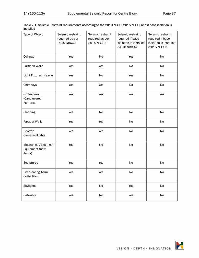
14Y160-113A Supplemental Seismic Report for Centre Block Page 37
Table 7.1. Seismic Restraint requirements according to the 2010 NBCC, 2015 NBCC, and if base isolation is installed
Type of Object Seismic restraint required as per 2010 NBCC?
Seismic restraint required as per 2015 NBCC?
Seismic restraint required if base isolation is installed (2010 NBCC)?
Seismic restraint required if base isolation is installed (2015 NBCC)?
Ceilings Yes No Yes No
Partition Walls Yes Yes No No
Light Fixtures (Heavy) Yes No Yes No
Chimneys Yes Yes No No
Grotesques (Cantilevered Features)
Yes Yes Yes Yes
Cladding Yes No No No
Parapet Walls Yes Yes No No
Rooftop Cameras/Lights
Yes Yes No No
Mechanical/Electrical Equipment (new items)
Yes No No No
Sculptures Yes Yes No No
Fireproofing Terra Cotta Tiles
Yes Yes No No
Skylights Yes No Yes No
Catwalks Yes No Yes No
14Y160-113A Supplemental Seismic Report for Centre Block Page 38
8. CONCLUSIONS
8.1 Challenges, Opportunities and Risks
Challenges in undertaking a seismic retrofit of the Centre Block and Peace include difficulties working around or with heritage finishes, and difficulty finding locations for new conventional reinforcing schemes that are acceptable from an architectural and heritage view point. An additional challenge includes working with incomplete information about such a complex building for both analyses of the structure and secondary structural components, and for the construction of a seismic upgrade.
There is also risk involved with the seismic upgrade of a heritage building, including damage to heritage features, the possibility of uncovering deterioration of the structure or unforeseen conditions. There is also risk of any new intervention have unintended negative impact on the structure through the restraint or release of load paths.
A seismic upgrade would also offer opportunities to insert new mechanical and electrical services in the building in conjunction with the upgrade, to add additional functional space while incorporating parts of the seismic upgrade into that new space, and to expand the scope of the foundation work for the seismic upgrade to insert transfer beams and remove columns in the basement. There is also an opportunity to include innovative structural solutions to save time and money or provide an additional level of performance beyond life safety.
Base isolating the structure and lowering the floor level of the basement would involve many complimentary activities, such as shoring and jacking, where savings could be realized. However, any seismic upgrade with localized foundation work could also be achieved without the complete excavation of the basement.
8.2 Further Investigations
Further investigations, testing and analyses are recommended to refine the results of the preliminary seismic analysis. Exploratory openings should be made or non-destructive testing used to confirm various structural dimensions, connections and configurations. Further testing should be completed to determine unknown properties of the brick and stone masonry, concrete and cementitious materials. A geotechnical investigation should be completed and connections of non-structural components should be verified.
8.3 Potential Seismic Upgrade Methods
8.3.1 Centre Block and Peace Tower Seismic Upgrade Methods
a) Both base isolation and conventional reinforcing methods, such as adding walls or steel braced frames for the Centre Block, and steel or FRP reinforcement for the Peace Tower, provide feasible seismic upgrade options to provide an increased level of safety in a seismic event by preventing collapse. However, a conventional seismic upgrade may not be feasible from a heritage preservation point of view;
b) A base isolation seismic upgrade can provide effective seismic protection to the heritage structure and finishes. A conventional seismic upgrade cannot. Significant damage to the
14Y160-113A Supplemental Seismic Report for Centre Block Page 39
structure’s masonry walls in a design earthquake event would still be anticipated even after a conventional seismic upgrade;
c) A base isolation seismic upgrade can provide a Post-Disaster level of performance, allowing for continued occupancy following a design earthquake event. This would be difficult to achieve with a conventional seismic upgrade;
d) A conventional seismic upgrade, and to a lesser extent a base isolation seismic upgrade, will require an upgrade of the Centre Block’s floor and roof diaphragms;
e) A base isolation seismic upgrade will require a ‘moat’ to be constructed around the perimeter of the structure. A conventional seismic upgrade will not; and
f) The size of the required seismic joint between the Centre Block and Peace Tower will be minimized by either a conventional seismic upgrade or base isolation of both structures together. A conventional seismic upgrade will minimize the size of the required seismic movement joints between the Library of Parliament and the Centre Block as well.
8.3.2 Operational and Function Components
a) The terra cotta fireproofing tiles that are suspended from the bottom flanges of the steel beams should be removed and replaced, or prevented from falling;
b) Suspended items, such as ceilings and light fixtures, should be restrained by installing angled cables. Restraint of the plaster ceiling will likely have visual impact;
c) Partition walls should be reinforced and connected to the structure above for out-of-plane motion;
d) Sculptures should be connected to the base, and the base should be connected to the floor. A connection to the wall or a cantilevered post behind the sculpture should be provided if required to prevent overturning;
e) Skylights should be configured so that the panes of glass will not fall out of the frame, either through ensuring that the frame is detailed properly, or by installing a film that will hold the glass together;
f) Reinforcement of exterior stonework should be compared to seismic loads. The condition of the connections should be accounted for in the calculations. Any unreinforced stonework should be reinforced;
g) Base-mounted items on the roof should be connected through the roofing to structural elements below;
h) Connections for the clock faces, carillon, flagpole, letter chute, and other decorative items should be compared to seismic loading and reinforced as required;
i) Loads and exemptions for seismic restraint may decrease in the 2015 NBCC; and
j) If base isolation is chosen for the building upgrade method, then the suspended and cantilevered items are the only items that will require restraint. This includes suspended ceilings, light fixtures, grotesques, and catwalks. It is still recommended that exterior stonework be restrained due to the potential for injury to people exiting the building.