supplementary certificate of approval · an automatic segment test is performed at the start of...
TRANSCRIPT

NMI 5/6A/222 Rev 15
Page 1 of 30
Certificate of Approval
NMI 5/6A/222
Issued by the Chief Metrologist under Regulation 60 of the
National Measurement Regulations 1999
This is to certify that an approval for use for trade has been granted in respect of the instruments herein described.
Gilbarco Model T920A6NP SK700-2 Fuel Dispenser for Motor Vehicles
submitted by Gilbarco Australia Limited 20 Highgate Street AUBURN NSW 2144
NOTE: This Certificate relates to the suitability of the pattern of the instrument for use for trade only in respect of its metrological characteristics. This Certificate does not constitute or imply any guarantee of compliance by the manufacturer or any other person with any requirements regarding safety.
This approval has been granted with reference to document NMI R 117-1, Measuring Systems for Liquids Other than Water, dated July 2004.
This approval becomes subject to review on 1/07/19, and then every 5 years thereafter.
DOCUMENT HISTORY
Rev Reason/Details Date
0 Pattern & variants 1 to 7 approved – interim certificate issued 12/06/09
1 Pattern & variants 1 to 7– certificate issued 14/12/09
2 Variant 8 approved – certificate issued 5/014/10
3 Variants 9 & 10 approved – certificate issued 20/08/10
4 Pattern & variants 1 to 10 consolidated – variant 11 approved – certificate re-issued by notification of change
18/02/11
5 Pattern & variants 1 to 11 – updated – variant 12 approved – certificate issued
2/09/11
6 Variants 13 & 14 approved – certificate issued 30/11/11
7 Variant 15 provisionally approved – interim certificate issued 2/12/11
8 Pattern amended (software version & Test Procedure) – variant 15 approved – certificate issued
13/02/13

NMI 5/6A/222 Rev 15
Page 2 of 30
Document History (cont…)
9 Variants 3 & 4 amended (flow rate switch) – variant 16 approved – certificate issued
24/05/13
10 Variant 16 amended – certificate issued 22/08/13
11 Variants 17 & 18 approved – certificate issued 22/11/13
12 Pattern & variants 1 & 18 updated & reviewed – variant 19 approved – certificate issued
16/05/14
13 Variants 20 & 21 approved – certificate issued 14/10/14
14 Variant 22 approved – certificate issued 29/10/15
15 Variants 23, 24 & 25 approved – certificate issued 01/03/17
CONDITIONS OF APPROVAL
General
Instruments purporting to comply with this approval shall be marked with approval number ‘NMI 5/6A/222’ and only by persons authorised by the submittor.
It is the submittor’s responsibility to ensure that all instruments marked with this approval number are constructed as described in the documentation lodged with the National Measurement Institute (NMI) and with the relevant Certificate of Approval and Technical Schedule. Failure to comply with this Condition may attract penalties under Section 19B of the National Measurement Act and may result in cancellation or withdrawal of the approval, in accordance with document NMI P 106.
Auxiliary devices used with this instrument shall comply with the requirements of General Supplementary Certificates No S1/0/A or No S1/0B.
Signed by a person authorised by the Chief Metrologist to exercise their powers under Regulation 60 of the National Measurement Regulations 1999.
Stephen Horrocks
signed
NMI 5/6A/222 Rev 15
Page 3 of 30
TECHNICAL SCHEDULE No 5/6A/222
1. Description of Pattern approved on 12/06/09
A Gilbarco model T920A6NP SK700-2 fuel dispenser for motor vehicles is approved to dispense various grades of fuels (*), in attendant-operated mode, or in attended self-service mode using any compatible (#) approved control console. The meter is adjusted to be correct for the liquid for which it is to be verified.
(*) including up to 10% ethanol (E10) and various grades of pure biodiesel and biodiesel/distillate blends (to Australian government standard).
(#) ‘Compatible’ is defined to mean that no additions/changes to hardware/software are required for satisfactory operation of the complete system.
1.1 Field of Operation
The field of operation of the measuring system is determined by the following characteristics:
• Minimum measured quantity, Vmin 2 L
• Maximum flow rate, Qmax 50 L/min
• Minimum flow rate, Qmin 5 L/min
• Maximum pressure of the liquid, Pmax 350 kPa
• Minimum pressure of the liquid, Pmin 140 kPa (#1)
• Range of liquids viscosity 0.5 to 20 mPa.s (at 20°C) (#2)
• Maximum temperature of the liquid, Tmax 50°C
• Minimum temperature of the liquid, Tmin -10°C
• Ambient temperature range -25 to 55°C
• Accuracy class 0.5
(#1) Minimum pressure required for effective operation of the gas elimination device.
(#2) The flowmeter is adjusted for use with one product viscosity. Fuels includekerosene, distillate and various grades of petrol (which may include up to 10%ethanol). The pattern and variants constructed for use to dispense various gradesof pure biodiesel and biodiesel/distillate blends (to Australian governmentstandard).
1.2 Description of the Metering System
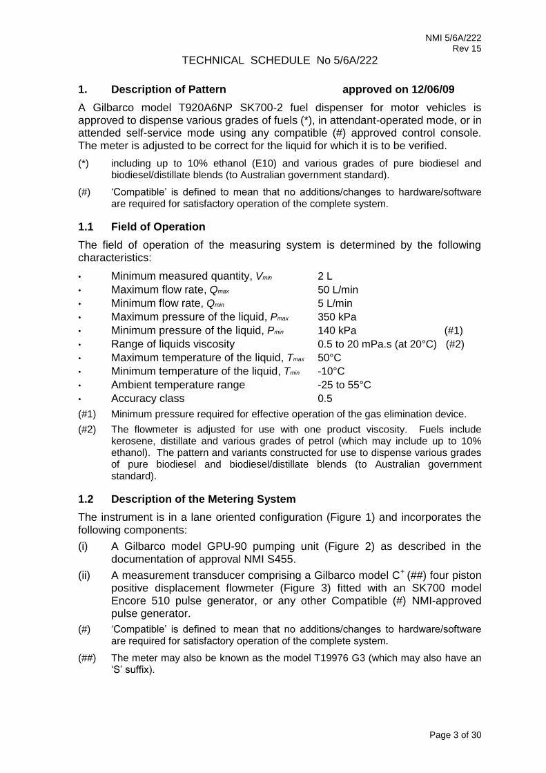
The instrument is in a lane oriented configuration (Figure 1) and incorporates the following components:
(i) A Gilbarco model GPU-90 pumping unit (Figure 2) as described in thedocumentation of approval NMI S455.
(ii) A measurement transducer comprising a Gilbarco model C+ (##) four pistonpositive displacement flowmeter (Figure 3) fitted with an SK700 modelEncore 510 pulse generator, or any other Compatible (#) NMI-approvedpulse generator.
(#) ‘Compatible’ is defined to mean that no additions/changes to hardware/softwareare required for satisfactory operation of the complete system.
(##) The meter may also be known as the model T19976 G3 (which may also have an‘S’ suffix).

NMI 5/6A/222 Rev 15
Page 4 of 30
(iii) A hose/nozzle, mounted on the side of the dispenser housing. The nozzleused is a 16 mm ZVA Elaflex nozzle. (*) The fuel dispenser is fitted with ahose retraction facility.
(*) Note that the submittor must be consulted regarding the acceptability of anyalternative nozzles.
1.3 Calculator/IndicatorA Gilbarco model Sandpiper 2 calculator/indicator (also known as the E101electronic set – Figure 4) which has a single display for indicating volume andanother for price. There is also a unit price display for each hose (Figure 1); anemergency stop may be provided in the vicinity of the indicating head.
The display limits and increments are:
Price 9999, 99 in 0.01 $ increments Volume 9999, 99 in 0.01 L increments Unit price 999, 9 in 0.1 ¢/L increments
The instrument is approved with versions 25xxx, 27xxx or 29xxx (*) software, which can be viewed by at power up or by forcing a restart by pushing the F1 then the F2 buttons on the Managers’ keypad.
(*) xxx may be a series of alphanumeric characters and may include hyphens, e.g. 27 A 04 154, 29 04 – 10 E, etc.
A pre-set device may also be fitted to allow pre-set to be selected by means of volume (litres) or price (dollars.
1.4 Descriptive Markings and Notices
Instruments are marked with the following data, together in one location on a data plate:
Pattern approval sign 5/6A/222 Manufacturer’s identification mark or trade mark ..... Manufacturer’s designation (model number) ..... Serial number ..... Year of manufacture ..... Maximum flow rate (Qmax) ..... L/min Minimum flow rate (Qmin) ..... L/min Minimum measured quantity (Vmin) ..... L (#1) Maximum operating pressure (Pmax) ..... kPa Minimum operating pressure (Pmin) ..... kPa Nature of liquids to be measured ..... (#2) Maximum temperature of the liquid, Tmax …..°C (#3) Minimum temperature of the liquid, Tmin …..°C (#3)
Environmental class class C
(#1) In addition, the minimum measured quantity (Vmin) shall be clearly visible on any indicating device visible to the user during measurement, in the form ‘Minimum delivery 2 L’.
(#2) e.g. distillate or D.
(#3) Required if liquid temperature range differs from -10°C to 50°C.
1.5 Sealing Provision
The gas separator test valve has provision for sealing. The meter calibration access is sealed as shown in Figure 5.

NMI 5/6A/222 Rev 15
Page 5 of 30
1.6 Verification Provision
Provision is made for the application of a verification mark.
1.7 Checking Facilities
An automatic segment test is performed at the start of each delivery.
The calculator monitors the presence and correct transmission of signal from the measurement transducer, and in the event of detecting a fault the instrument indicates an error code and has provision for controlling electrically-operated valves to stop the delivery.
2. Description of Variant 1 approved on 12/06/09
Certain other models and configurations of the T92*** SK700-2 series of fuel dispensers identified using Table 1 below.
TABLE 1 – Meaning of model designations for the T92*** SK700-2 series of fuel dispensers:
(the pattern is a model T920A6NP SK700-2)
1st, 2nd and 3rd digits, Series;
T92 = Gilbarco Australia product, base model
4th digit, Models, e.g.;
0 = lane oriented with hose retraction (the pattern)
4 = lane oriented without hose retraction (variant 9)
8 = island oriented with flexmast (variant 11)
9 = island oriented without flexmast (variant 11)
5th digit = Country code;
A= Australia
6th digit N = Number of hoses;
1 to 12 (for up to 6 petrol grades)
7th = Flow rate;
N = Normal (50 L/min, or 42 L/min when fitted with vapour recovery)
H = High (90 L/min)
E = Extended (130 L/min)
U = Ultra high (160 L/min)
M = Mixed (combination of N and H hydraulics)
8th = Hydraulic module;
P = Pump (suction pumping unit, either type GDP-90 or GDP-140)
D = Dispenser (pressure system using approved submersible turbine pump) P/D = Combined Pumps and Dispensers (Variant 24)
Suffix = Primary/satellite configuration, only present if complying with variant 10
‘M’ = Primary
‘S’ = Satellite
‘B’ = Primary/Satellite
‘A’ = Integrated AdBlue hydraulic module (variant 13)
‘2’ = 2 × Petrol/Diesel hydraulic modules (variant 14)
Blank = If variants 10 or 13 or 14 configuration not used, or if only one hydraulic module.

NMI 5/6A/222 Rev 15
Page 6 of 30
3. Description of Variant 2 approved on 12/06/09
With one or more Gilbarco model Eco screw type flowmeters (Figure 6) instead of the model C+ flowmeters described for the pattern. This meter is fitted with an Eltomatic model ME 01 04 pulse generator.
4. Description of Variant 3 approved on 12/06/09
With standard pumps as described for the pattern, but with 25 mm piping, 25 mm hoses, and ZVA Elaflex 25 mm nozzles (*), and known as High flow rate fuel dispensers with the following field of operation:
• For use with distillate
• Maximum flow rate (Qmax) 90 L/min
• Minimum flow rate (Qmin) 9 L/min
• Minimum measured quantity (Vmin) 5 L
5. Description of Variant 4 approved on 12/06/09
With Gilbarco model GPU-140 pumping units with 32 mm piping, 32 mm hoses, and ZVA Elaflex 32 mm nozzles (*), and known as Extended flow rate fuel dispensers with the following field of operation:
• For use with distillate
• Maximum flow rate (Qmax) 130 L/min
• Minimum flow rate (Qmin) 13 L/min
• Minimum measured quantity (Vmin) 5 L
6. Description of Variant 5 approved on 12/06/09
With two Gilbarco model GPU-90 pumping units in parallel, with 32 mm piping, 32 mm hoses, and ZVA Elaflex 32 mm nozzles (*), and known as Ultra-high flow rate fuel dispensers with the following field of operation:
• For use with distillate
• Maximum flow rate (Qmax) 160 L/min
• Minimum flow rate (Qmin) 16 L/min
• Minimum measured quantity (Vmin) 5 L
(*) Note that the submittor must be consulted regarding the acceptability of any alternative nozzles.
7. Description of Variant 6 approved on 12/06/09
With one or more compatible submersible turbine pumps (STPs) incorporating a leak detection system (Figure 7). The STP replaces the equivalent components (i.e. motor, pump/strainer/gas separator, and associated pipework) in certain fuel dispensers covered by this approval.
Dispensers may operate with the standard maximum flow rate, Qmax of 50 L/min, or dispensers for use with distillate may be used with the Ultra-high maximum flow rate, Qmax of 160 L/min.

NMI 5/6A/222 Rev 15
Page 7 of 30
8. Description of Variant 7 approved on 12/06/09
Instruments are fitted with a Gilbarco Stage 2 (VR2) vapour recovery and monitoring system and are used up to a maximum flow rate of 42 L/min. A typical instrument is shown in Figure 8.
The vapour recovery and monitoring system is approved by the German TÜV SÜD Industrie Service GmbH authority.
Only vapour recovery components and systems as listed below and included in the relevant TÜV approval certificates may be used.
The relevant TÜV approvals (and the approved components) are:
(i) For collection of vapour:
TÜV 85-2.128 (electric valves); or
TÜV 85-2.160 (manual valves),
and the only approved system components are:
Vapour recovery nozzles – Elaflex models ZVA 200 GR, ZVA SLIMLINE 2 GR, or ZVA SLIMLINE 2 GRVP.
Coaxial hose – Elaflex model Conti Slimline 21/8 Coax.
Control valves – Burkert model 6022 / 2832.
Control board – Gilbarco model VRC 390/x.
Vapour recovery pump(s) – Durr models MEX 0831-10, MEX 0831-11, or MEX 0544.
(ii) For automatic monitoring of the vapour to fuel ratio:
TÜV UE-12.5,
and the only approved system components are:
Gilbarco (GVR) model VMC monitor.
Gilbarco (GVR) model GE1 flowmeter.
9. Description of Variant 8 approved on 2/014/10
The pattern and variants for use to dispense various grades of petrol which may include up to 85% ethanol (‘E85’).
10. Description of Variant 9 approved on 19/08/10
Certain models of this approval without a hose retraction facility (Figure 9). Instruments may be identified using Table 1. The series number is ‘T924*’.
11. Description of Variant 10 approved on 19/08/10
Any fuel dispenser of this approval now used with a satellite dispenser (Figure 10) for deliveries to trucks that have fuel tanks on both sides of the vehicle – for this variant, the original dispenser is then known as the primary dispenser.
The primary dispenser has all the required hydraulics to connect to the satellite dispenser via underground cabling and piping.

NMI 5/6A/222 Rev 15
Page 8 of 30
Each satellite dispenser is associated with a primary dispenser. Each satellite dispenser has a display and nozzle only that is controlled from the primary unit.
The two fuel dispensers are adjacent to each other with sufficient space between for the vehicle. The primary dispenser includes the calculator while both instruments have an indicator for monitoring the deliveries from either dispenser, showing the total delivery whether both or just one dispenser is used. A single fuel delivery may be started by using either the primary or satellite nozzle and completed, if necessary, by using the other nozzle.
Instruments may be identified using Table 1. Instrument model numbers now include a suffix, namely ‘M’ = Primary, ‘S’ = Satellite, or ‘B’ = Primary/Satellite (primary on one side of the dispenser and satellite on the other side, for connection to other satellite and primary dispensers, respectively).
12. Description of Variant 11 approved on 17/02/11
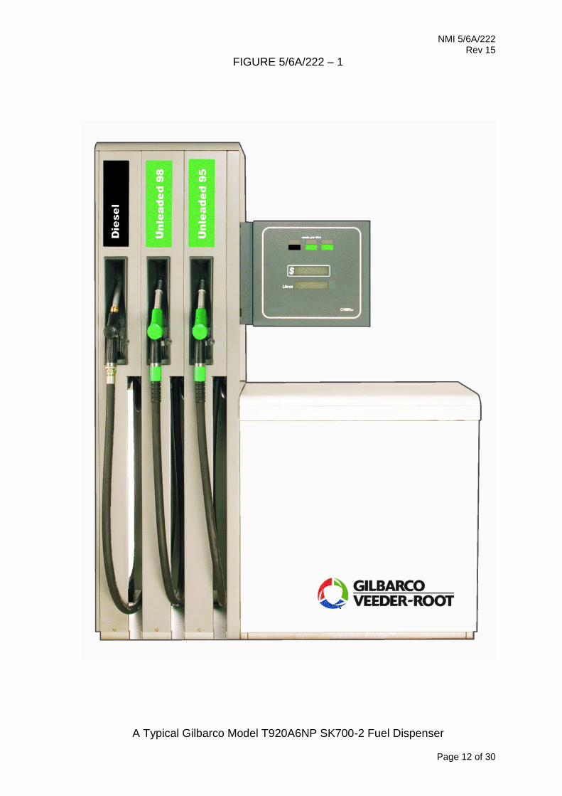
The T928* or T929* series of Island Oriented Dispensers (IOD) (Figure 11).
Instruments may be identified using Table 1 (included in Technical Schedule 5/6A/222), where the series number is ‘T928*’ (when fitted with a flexmast facility) or ‘T929*’ (when instruments are without a flexmast facility).
Instrument model numbers may also include a suffix as described in variant 10 for primary/satellite instruments.
13. Description of Variant 12 approved on 2/09/11
Instruments may be fitted with an updated version of the Gilbarco model Sandpiper 2 calculator/indicator (also known as the E101 electronic set) which is similar to the version described for the pattern but which has a larger price and volume display and (Figure 12) and may also be in a variety of indicator housings (Figure 12 shows a ‘Slimline’ style with pre-set). Multiple unit price displays are provided for each hose and are positioned vertically next to the main price and volume display. When a hose is selected each of the unit price displays are blanked and the unit price for the selected hose is updated on a separate display below the main price and volume display.
A pre-set device may also be fitted to allow pre-set to be selected by means of volume (litres) or price (dollars).
14. Description of Variant 13 approved on 30/11/11
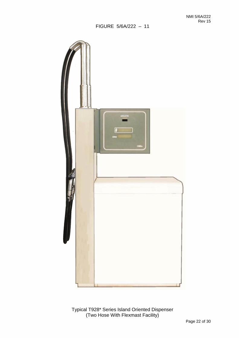
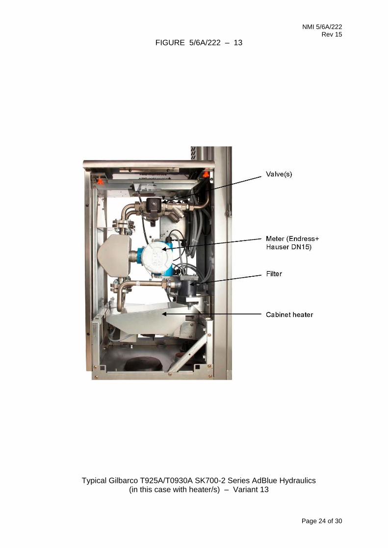
Certain models of the T92*** SK700-2 series of dispensers identified using Table 1 fitted with one or more Gilbarco model C+ (##) four piston positive displacement flowmeters and one or two Endress+Hauser model LPG mass DN15 15 mm Coriolis principle mass flowmeters (Figures 13 and 14).
The Gilbarco model C+ (##) meter is approved for use as described for the pattern.
The Endress+Hauser model LPG mass DN15 15 mm meters are approved dispense only AdBlue fluid AUS32 (aqueous urea solution 32.5%) over a flow rate range of 4 to 40 L/min, for certain motor vehicles having heavy duty diesel engines fitted with a Selective Catalytic Reduction (SCR) unit in attendant operated mode.
(##) The meter may also be known as the model T19976 G3 (which may also have an ‘S’ suffix).

NMI 5/6A/222 Rev 15
Page 9 of 30
14.1 Field of Operation
The field of operation of the model Gilbarco model C+ meter is as described for the pattern. The field of operation of the AdBlue measuring system is determined by the following characteristics:
• Minimum measured quantity, Vmin 2 L
• Maximum flow rate, Qmax 40 L/min
• Minimum flow rate, Qmin 4 L/min
• Maximum pressure of the liquid, Pmax 320 kPa
• Minimum pressure of the liquid, Pmin 50 kPa (#1)
Dynamic viscosity (at 25°C) 1.4 mPa.s (#2)
Maximum temperature of the liquid, Tmax 30°C
Minimum temperature of the liquid, Tmin 0°C
• Ambient temperature range -25 to 55°C
• Accuracy class 0.5
(#1) Minimum pressure required for effective operation of the gas elimination device.
(#2) The flowmeter is adjusted to be correct for AdBlue fluid AUS32 (aqueous urea solution 32.5%) for which it is to be verified.
14.2 Sealing Provision
The meter calibration access is sealed as shown in Figure 5.
15. Description of Variant 14 approved on 30/11/11
Certain models of the T92*** SK700-2 series of dispensers identified using Table 1 fitted with two separate hydraulic cabinets, each may contain petrol and/or distillate hydraulics, in a housing of the style shown in Figure 14.
16. Description of Variant 15 provisionally approved on 2/12/11 approved on 13/02/13
With an amended unit price change operation for single grade pumps and dispensers only, when the unit price is changed from the control console the old unit price and transaction data are reset to 0.00. The new unit price will not be displayed until the nozzle is lifted, and when the nozzle is lifted for the first time the unit price is displayed for 5 seconds before the delivery may start. Once used the first time the new unit price will be retained on the display and there will be no (5 second) delay before a delivery may commence.
17. Description of Variant 16 approved on 24/05/13
Any model dispenser complying with variants 3 or 4 now fitted with one or more low/high flow rate selection button. When the delivery starts the fuel dispenser will start in the lower flow rate as per the Field of Operation for the pattern; if the selection button (Figure 15) is pushed the maximum possible flow rate will increase up to the maximum specified in the Field of Operation of the particular
variant, i.e. either ‘mid flow’ (variant 3) or ‘ultra high flow’ (variant 4).

NMI 5/6A/222 Rev 15
Page 10 of 30
18. Description of Variant 17 approved on 22/11/13
For use with a single Price Per Unit (PPU) indicator (Figure 16). When Fuel disperser is idle the PPU display shows the last used grade PPU, if a nozzle is lifted the PPU display changes to the selected grade as the Price and Volume displays are reset showing zeros. If the nozzle is hung up, without being authorised, then the last delivery data is restored. If a new PPU value is assigned to a grade, or displayed for the first time, then it will be shown for 5 seconds before a delivery is possible.
19. Description of Variant 18 approved on 22/11/13
With a Gilbarco model Multi Media Display (MMD) calculator/indicator which has a large LCD type indicator (Figure 17) which shows the price, volume, and unit price of the current sale, plus unit prices for each product, and in addition has a section available for non-measurement related information. The measurement related display limits and increments are the same as for the pattern, namely:
Price up to 9999.99 in 0.01 $ increments Volume up to 9999.99 in 0.01 L increments Unit price up to 999.9 in 0.1 ¢/L increments
The displayed transaction data is maintained during power failure for a minimum of 15 minutes by the use of a model MINI-DC-UPS/12DC/4 uninterruptible power supply (UPS) in conjunction with model MINI-BATT/12DC/2.6AH batteries (2 off)
or any compatible (#) UPS or batteries.
The instrument is approved with the same software versions as the pattern (refer to clause 1.3).
20. Description of Variant 19 approved on 16/05/14
With one or more Gilbarco model V flowmeters (Figure 18) which may also be known as the model +V, instead of the model C+ flowmeters described for the pattern. This meter is fitted with an Encore 510 pulse generator.
20.1 Field of Operation
The field of operation of the model Gilbarco model V (or V+) meter is the same as for the C+ meter (clause 1.1 for the pattern) except as follows:
• Maximum temperature of the liquid, Tmax 40°C • Minimum temperature of the liquid, Tmin -10°C • Ambient temperature range -10 to 55°C
21. Description of Variant 20 approved on 14/10//14
For use with the following Husky nozzles:
Husky VIII, Diesel high flow only (32 mm spout) Husky 1A, ULP low flow & High flow Diesel & (19 mm) Husky 1+X, Low flow only Diesel or ULP
22. Description of Variant 21 approved on 14/10/14
For use with the component mentioned in Variant 7, instead of using an Elaflex models ZVA 200 GR, ZVA SLIMLINE 2 GR, or ZVA SLIMLINE 2 GRVP they may be replaced by a Husky V34 Vapour Recovery VR2 ULP Nozzle.

NMI 5/6A/222 Rev 15
Page 11 of 30
23. Description of Variant 22 approved on 29/10/15
Similar to variant 13 except that the mass meter is connected by ‘ModBus’ wiring in which case the K-factor used for calibration is stored in the meter.
23.1 Sealing Provision
When ‘ModBus’ wiring is used the meter calibration access is sealed as shown in Figure 19.
24. Description of Variant 23 approved on 01/03/17
For use with Gilbarco model Apollo calculator/indicator.
25. Description of Variant 24 approved on 01/03/17
Combined pressure and suction pumps in a common chassis known as a model T920A8N(P/D). Refer to variant 1 for model description. One or more GPU-90 and/or GPU-140 pumping units are installed in some but not all positions.
26. Description of Variant 25 approved on 01/03/17
With one or more Krohne model BatchFlux 3200C electromagnetic flowmeters (Figure 20 & 21) for dispensing Diesel Exhaust Fluid (DEF) also known as AdBlue fluid AUS32 (aqueous urea solution 32.5%).
TEST PROCEDURE No 5/6A/222
Instruments shall be tested in accordance with any relevant tests specified in the National Instrument Test Procedures.
Tests should be conducted in conjunction with any tests specified in the approval documentation for any components used, including indicator/controller and submersible turbine pump (STP) hydraulic systems.
The instrument shall not be adjusted to anything other than as close as practical to zero error, even when these values are within the maximum permissible errors.
Maximum Permissible Errors
The maximum permissible errors are specified in Schedule 1 of the National Trade Measurement Regulations 2009.
NMI 5/6A/222 Rev 15
Page 12 of 30
FIGURE 5/6A/222 – 1
A Typical Gilbarco Model T920A6NP SK700-2 Fuel Dispenser

NMI 5/6A/222 Rev 15
Page 13 of 30
FIGURE 5/6A/222 – 2
Gilbarco Model GPU-90 Pumping Unit (without inlet filter bowl)
Gilbarco Model GPU-90 Pumping Unit (rear view no inlet filter bowl)

NMI 5/6A/222 Rev 15
Page 14 of 30
FIGURE 5/6A/222 – 3
A Gilbarco Model C+ Flowmeter (aka Model T19976 G3)

NMI 5/6A/222 Rev 15
Page 15 of 30
FIGURE 5/6A/222 – 4
Power Supply and Driver Printed Circuit Boards
Processor PCB and Interface Cards
Sandpiper 2 Calculator/Indicator (aka Model E101) Electronics (typical mounting arrangement)

NMI 5/6A/222 Rev 15
Page 16 of 30
FIGURE 5/6A/222 – 5
Typical Sealing of Meter Calibration Access (using destructible adhesive labels)
Examples of Different Seal Details

NMI 5/6A/222 Rev 15
Page 17 of 30
FIGURE 5/6A/222 – 6
Gilbarco Model Eco Flowmeter

NMI 5/6A/222 Rev 15
Page 18 of 30
FIGURE 5/6A/222 – 7
Typical Submersible Turbine Pump (STPs) System

NMI 5/6A/222 Rev 15
Page 19 of 30
FIGURE 5/6A/222 – 8
Typical Gilbarco Stage 2 (VR2) Vapour Recovery Collection and Monitoring Hydraulic System

NMI 5/6A/222 Rev 15
Page 20 of 30
FIGURE 5/6A/222 – 9
Typical T924* Series Dispenser Without a Hose Retraction Facility

NMI 5/6A/222 Rev 15
Page 21 of 30
FIGURE 5/6A/222 – 10
Satellite Primary Dispenser Dispenser
A Typical Satellite Dispensing System – Variant 10
NMI 5/6A/222 Rev 15
Page 22 of 30
FIGURE 5/6A/222 – 11
Typical T928* Series Island Oriented Dispenser (Two Hose With Flexmast Facility)

NMI 5/6A/222 Rev 15
Page 23 of 30
FIGURE 5/6A/222 – 12
Gilbarco Model Sandpiper 2 Calculator/Indicator – Updated Display Version (‘Slimline’ Head Style Housing)
NMI 5/6A/222 Rev 15
Page 24 of 30
FIGURE 5/6A/222 – 13
Typical Gilbarco T925A/T0930A SK700-2 Series AdBlue Hydraulics (in this case with heater/s) – Variant 13

NMI 5/6A/222 Rev 15
Page 25 of 30
FIGURE 5/6A/222 – 14
Typical Gilbarco SK700-2 with 2 Hydraulic modules (Variants 13 and 14) (in this case including with AdBlue – Variant 13)

NMI 5/6A/222 Rev 15
Page 26 of 30
FIGURE 5/6A/222 – 15
Typical Low/High Flow Rate Selection Button – Variant 16

NMI 5/6A/222 Rev 15
Page 27 of 30
FIGURE 5/6A/222 – 16
Showing Single Price Per Unit (PPU) Indicator (Variant 17)
FIGURE 5/6A/222 – 17
Showing Gilbarco Model Multi Media Display (MMD) Calculator/Indicator (Variant 18)

NMI 5/6A/222 Rev 15
Page 28 of 30
FIGURE 5/6A/222 – 18
Gilbarco Model V (aka V+) Flowmeter (Variant 19)

NMI 5/6A/222 Rev 15
Page 29 of 30
FIGURE 5/6A/225 – 19
Typical Sealing of Coriolis Meter Calibration Access Including ModBus Connections (Variant 22)

NMI 5/6A/222 Rev 15
Page 30 of 30
FIGURE 5/6A/230 – 20
Krohne Model Batchflux 3200C Electromagnetic Flowmeter (Variant 25)
FIGURE 5/6A/230 – 21
Sealing is via wire and lead slug. In Australian model dispensers the slug will be mounted in a retaining cup that is
secured to the dispenser frame
~ End of Document ~