supplementary certificate of approval · rev 4 . page 1 of 15 . supplementary certificate of...
TRANSCRIPT
NMI S556 Rev 4
Page 1 of 15
Supplementary Certificate of Approval
NMI S556
Issued by the Chief Metrologist under Regulation 60 of the
National Measurement Regulations 1999
This is to certify that an approval for use for trade has been granted in respect of the instruments herein described.
SysTec Model IT9000E Digital Indicator
submitted by SCACO Pty Ltd (formerly Scale Components Pty Ltd)
4 Dan Street Slacks Creek QLD 4127
NOTE: This Certificate relates to the suitability of the pattern of the instrument for use for trade only in respect of its metrological characteristics. This Certificate does not constitute or imply any guarantee of compliance by the manufacturer or any other person with any requirements regarding safety. This approval has been granted with reference to document NMI R 76, Non-automatic weighing instruments, Parts 1 and 2, dated July 2004. This approval becomes subject to review on 1/11/16, and then every 5 years thereafter.
DOCUMENT HISTORY
Rev Reason/Details Date 0 Pattern approved – interim certificate issued 17/10/11 1 Pattern – certificate issued 24/02/12 2 Variants 1 to 4 approved – certificate issued 7/12/12 3 Variants 5 to 7 approved – certificate issued 5/08/15 4 Variants 8 to 9 approved & amended (submittor name) –
certificate issued 29/06/17
NMI S556 Rev 4
Page 2 of 15
CONDITIONS OF APPROVAL General Instruments purporting to comply with this approval shall be marked with approval number ‘NMI S556’ and only by persons authorised by the submittor. Instruments incorporating a component purporting to comply with this approval shall be marked ‘NMI S556’ in addition to the approval number of the instrument, and only by persons authorised by the submittor. It is the submittor’s responsibility to ensure that all instruments marked with this approval number are constructed as described in the documentation lodged with the National Measurement Institute (NMI) and with the relevant Certificate of Approval and Technical Schedule. Failure to comply with this Condition may attract penalties under Section 19B of the National Measurement Act and may result in cancellation or withdrawal of the approval, in accordance with document NMI P 106. Auxiliary devices used with this instrument shall comply with the requirements of General Supplementary Certificates No S1/0/A or No S1/0B.
Signed by a person authorised by the Chief Metrologist to exercise their powers under Regulation 60 of the National Measurement Regulations 1999.
Dr A Rawlinson

NMI S556 Rev 4
Page 3 of 15
TECHNICAL SCHEDULE No S556
1. Description of Pattern approved on 17/10/11 A SysTec model IT9000E digital mass indicator (Figure 1a and Table 1) which may be configured to form part of:
• A weighing instrument with a single weighing range of up to 6000 verification scale intervals; or
• A multi-interval instrument with up to three partial weighing ranges (each with its own verification scale interval) in which case it is approved for use with up to 6000 verification scale intervals per partial weighing range; or
• A multiple range weighing instrument with up to three weighing ranges, in which case it is approved for use with up to 6000 verification scale intervals per weighing range.
The changeover between weighing ranges is automatic. The instrument has two scale interface analog to digital converter (ADM) modules fitted within a stainless steel enclosure and having a liquid crystal display (LCD) for indication of the weight value and for alphanumeric information. Instruments may be fitted with output sockets (output interfacing capability) for the connection of auxiliary and/or peripheral devices (see clause 1.6 below).
TABLE 1 – Specifications for the Pattern
Maximum number of verification scale intervals 6000 (class ) 1000 (class ) Minimum sensitivity 0.33 µV / scale interval Excitation voltage 5 V DC Maximum excitation current 238 mA (#) Fraction of maximum permissible error pi = 0.5 Minimum load cell impedance 21 Ω Maximum load cell impedance 4500 Ω Measuring range minimum voltage 0 mV Measuring range maximum voltage 30 mV Maximum tare range -100% Max Operating temperature range -10°C to +40°C Load cell connection 4-wire or 6-wire shielded (#) This maximum excitation current value applies to each load cell connection
(ADM) module – see clauses 1.5 and 1.6 below. Where two ADM modules are fitted, the total available excitation current is 476 mA.
This approval does not include the use of the indicator as an automatic weighing instrument, unless specifically mentioned in a certificate of approval for such an instrument.
1.1 Zero A zero-tracking device may be fitted. The initial zero-setting device has a nominal range of not more than 20% of the maximum capacity of the instrument. The instrument has a semi-automatic zero-setting device with a nominal range of not more than 4% of the maximum capacity of the instrument.

NMI S556 Rev 4
Page 4 of 15
1.2 Tare A semi-automatic subtractive tare device and non-automatic keyboard-entered pre-set subtractive tare device, each of up to maximum capacit y o f t he inst rum ent (except for instruments configured as multi-interval instruments, in which case the maximum pre-set tare value is Max1), may be fitted.
1.3 Display Check A display check is initiated whenever power is applied.
1.4 Power Supply The power supply may be either 110–240 V AC (mains power) or 12–30 V DC.
1.5 Load Cell Connection (ADM) Module(s) The indicator is able to be provided with two scale interface analog to digital converter (ADM) modules (which plug into the main board of the indicator). When provided with two ADM modules it is possible for two baseworks to be connected to a single IT9000E digital indicator. Note: Each ADM also contains a memory device so that calibration parameters of the platform can be stored. However it should be noted that if the indicator is replaced or repaired, re-verification of the instrument is required.
1.6 Multi Baseworks Facility (a) Individual weight display Up to a maximum of ten baseworks may be connected to a single IT9000E digital indicator using one or two additional external scale multiplexers – ADCBox (Figure 1b). Each ADCBox may hold up to four additional ADM modules.
The ‘Scales Select’ key ( ) is used to select a platform. Note: In the case of this feature including the summing weight function (clause
1.6(b) below), each basework/combination shall be clearly identified to correspond to the appropriate scale display shown on the indicator. That is, there shall be a clear correspondence between the basework identification and the scale selected indication (shown by illumination of ‘W1’, ‘W2’, or ‘W3’). Trade measurement officers may require additional markings or signs to ensure that these relationships are clear.
(b) Summing weight display (1.) Two baseworks:
When two baseworks are connected to a single IT9000E indicator it is also possible for a function to be selected in which the summed weight on the platforms is displayed.
The ‘Scales Select’ key ( ) key of the indicator is used to select this function – when selected ‘W3’ is indicated rather than ‘W1’ or ‘W2’. ‘W3’ represents the weight on both platforms 1 and 2.
NMI S556 Rev 4
Page 5 of 15
Notes: (i) W1, W2 and the summing weight function (W3) shall be in single interval
operation. (ii) The verification scale interval for W1, W2 and the summing weight function
(W3) shall be the same. (iii) When the summing weight function (W3) is in use, tare is not operational in
this mode (gross weight only is displayed).
(2.) Up to ten baseworks: Up to ten baseworks may be connected to a single IT9000E digital indicator. This will require two ADCBoxes and eight additional internal ADM modules. A separate summing weight display is provided.
The ‘Scales Select’ key ( ) is used to select a platform. Note: Tare is not operational in this mode (gross weight only is displayed).
1.7 Data Storage Memory The indicator may contain memory for the storage of weighing results. For each weighing, weighing results together with identification including date and time are stored into the storage device. The use of this feature for trade use is subject to the agreement of the applicable trade measurement authority. In any case, data from the storage device shall only be used for trade if the format of the output complies with General Supplementary Certificates No S1/0/A or S1/0/B.
1.8 Interfaces The indicator may be fitted with interfaces for the connection of auxiliary and/or peripheral devices. Any interfaces shall comply with clause 5.3.6 of document NMI R76 (the basic intent of which is that it shall not be possible to alter weighing results via the interfaces). Any measurement data output from the instrument or its interfaces shall only be used for trade in compliance with General Supplementary Certificates No S1/0/A or S1/0/B (in particular in regard to the data and its format). Indications other than the indications of measured mass (i.e. gross, tare, net, totals) displayed either on the indicator or on an auxiliary or peripheral device, are not for trade use. Instruments may be fitted with RS-232/RS422/RS485 serial data interfaces, 20 mA current loop interface, Profibus, DeviceNet, CAB-Bus, Ethernet and USB interfaces and digital inputs/outputs.
1.9 Linearisation Facility Instruments are fitted with a linearisation correction facility having up to six correction points.
1.10 Verification Provision Provision is made for the application of a verification mark.
NMI S556 Rev 4
Page 6 of 15
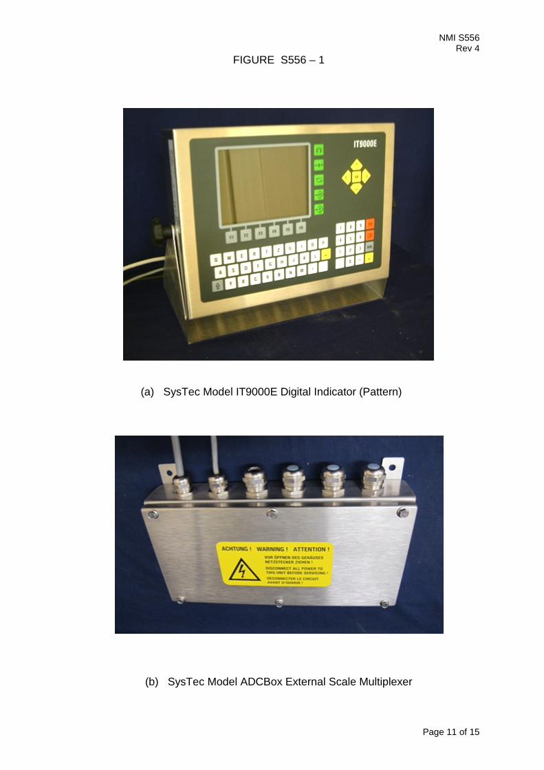
1.11 Sealing Provision Provision is made for the calibration adjustments to be sealed by the use of at least two destructible adhesive labels one at each side of the back cover plate of the instrument (Figure 2a) and/or one at each side of ADCBox case (Figure 2b). The calibration parameters are stored within the ADM module for each platform. The ability to change these parameters is inhibited when the jumper ‘W1’ on each ADM module is in the protected location (connecting pins 1 and 2, as shown in Figure 2c).
1.12 Markings and Notices Instruments carry the following markings:
Manufacturer’s mark, or name written in full Systec Systemtechnik and Industrieautomation GmbH, Germany Name or mark of manufacturer’s agent SCACO Indication of accuracy class or Maximum capacity (for each range) Max ..... kg #1 Minimum capacity (for each range) Min …... kg #1 Verification scale interval (for each range) e = ....... kg #1 Maximum subtractive tare T = - ..... kg #2 Serial number of the instrument …........ Pattern approval mark for the indicator NMI S556 Pattern approval mark for other components .............. #3
#1 These markings are also shown near the display of the result if they are not already located there.
#2 This marking is required if T is not equal to Max. #3 May be located separately from the other markings. In addition, instruments not greater than 100 kg capacity carry a notice stating NOT TO BE USED FOR TRADING DIRECT WITH THE PUBLIC, or similar wording. Note: For multi-interval instruments the markings shall be as above, with the exception that the ‘Maximum capacity’ and ‘Verification scale interval’ shall be marked for both interval ranges, e.g. as follows: Maximum capacity Max …. / …. kg Verification scale interval e = ….. / ….. kg For multiple range instruments, the maximum capacity, minimum capacity and verification scale interval for each range shall be marked, with an indication of the range to which they apply, e.g.
Range ( )1.1 ( )1.2 ( )1.3 Max …. kg …. kg …. kg Min …. kg …. kg …. kg
e = …. kg …. kg …. Kg

NMI S556 Rev 4
Page 7 of 15
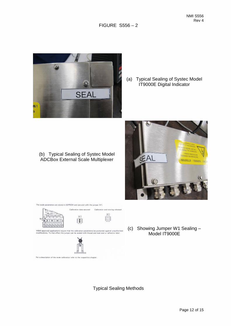
2. Description of Variant 1 approved on 7/12/12 A SysTec model IT8000E indicator (Figure 3) which is similar to the pattern but with the parameters as shown in Table 2 below. Up to six baseworks may be connected to a single IT8000E digital indicator. This will require one ADCBox and four additional internal ADM modules. A separate summing weight display is provided.
The ‘Scales Select’ key ( ) is used to select a platform. Note: Tare is not operational in this mode (gross weight only is displayed).
TABLE 2 – Specifications for Variants 1 to 4
Maximum number of verification scale intervals 6000 (class ) 1000 (class ) Minimum sensitivity 0.33 µV / scale interval Excitation voltage 5 V DC Maximum excitation current 116 mA # Fraction of maximum permissible error pi = 0.5 Minimum load cell impedance 43 Ω Maximum load cell impedance 4500 Ω Measuring range minimum voltage 0 mV Measuring range maximum voltage 30 mV Maximum tare range -100% Max Operating temperature range -10°C to +40°C Load cell connection 4-wire or 6-wire shielded # These specifications apply to each load cell connection (ADM) module –
see clauses 1.5 and 1.6. Where two ADM modules are fitted, the total available excitation current is 232 mA.
3. Description of Variant 2 approved on 7/12/12 A SysTec model IT6000E indicator (Figure 4) which is similar to the model IT8000E (variant 1) but without a QWERTY keypad. The indicator is fitted with one ADM module.
4. Description of Variant 3 approved on 7/12/12 A SysTec model IT4000E indicator (Figure 5) which is similar to the model IT6000E (variant 2) but may only be used with compatible approved analogue load cells.
5. Description of Variant 4 approved on 7/12/12 The SysTec models IT8000E and IT6000E (variants 1 and 2, respectively) may be used with compatible approved Flintec digital RC3 load cells. The maximum number of scale intervals (VSI) applicable is determined by the number of VSI given in the approval documentation for the load cells used.

NMI S556 Rev 4
Page 8 of 15
6. Description of Variant 5 approved on 5/08/15 A Systec model IT8000ET indicator (Figure 6 and Table 3) which is similar to the pattern and may be configured to form part of: • A class weighing instrument with a single weighing range of up to
6000 verification scale intervals; or
• A class weighing instrument with a single weighing range of up to 1000 verification scale intervals.
• A class multi-interval weighing instrument with up to three partial weighing ranges (each with its own verification scale interval) in which case it is approved for use with up to 6000 verification scale intervals per partial weighing range; or
• A class multi-interval weighing instrument with up to three partial weighing ranges (each with its own verification scale interval) in which case it is approved for use with up to 1000 verification scale intervals per partial weighing range.
• A class multiple range weighing instrument with up to three weighing ranges, in which case it is approved for use with up to 6000 verification scale intervals per weighing range.
• A class multiple range weighing instrument with up to three weighing ranges, in which case it is approved for use with up to 1000 verification scale intervals per weighing range.
The changeover between weighing ranges is automatic. The instrument has two scale interface analog to digital converter (ADM) modules fitted within a stainless steel enclosure and having a touch screen LCD display/keyboard for indication of the weight value. The power supply may be either a SysTec model ITX000ET external power supply or 12 – 30 V DC.
TABLE 3 – Specifications for Variants 5 to 7
Maximum number of verification scale intervals 6 000 (class ) 1000 (class )
Minimum sensitivity 0.33 µV/scale interval Excitation voltage 5 V DC Maximum excitation current 116 mA Fraction of maximum permissible error pi = 0.5 Minimum load cell impedance 43 Ω Maximum load cell impedance 3300 Ω Measuring range minimum voltage 0 mV Measuring range maximum voltage 30 mV Maximum tare range -100% Max Operating temperature range -10°C to +40°C Load cell connection 4 or 6 wire shielded # These specifications apply to each load cell connection (ADM)
module – see clauses 1.5 and 1.6. Where two ADM modules are fitted, the total available excitation current is 232 mA.
NMI S556 Rev 4
Page 9 of 15
Up to eight baseworks may be connected to a single IT8000ET digital indicator. This will require two ADCBoxes (Figure 2b) and six additional internal ADM modules. A separate summing weight display is provided.
The ‘Scales Select’ key ( ) is used to select a platform. Note: Tare is not operational in this mode (gross weight only is displayed).
6.1 Interface Instruments may be fitted with RS-232/RS422/RS485 serial data interfaces, Profibus, ProfiNet, Ethernet and USB interfaces, digital inputs/outputs and analogue inputs/outputs.
6.2 Software Version The software is identified by a checksum number 15487782 and designated version V4.x.y, where ‘x.y’ refers to the identification of non-legally relevant software. The software checksum and version can be seen by pressing and holding weight display for minimum 2 seconds (the identification is displayed momentarily), and then pressing the right arrow button, the software checksum and version are displayed.
7. Description of Variant 6 approved on 5/08/15 A SysTec model IT6000ET indicator (Figure 6) which is similar to the model IT8000ET (variant 5) but the indicator is fitted with one ADM module.
8. Description of Variant 7 approved on 5/08/15 The SysTec models IT8000ET and IT6000ET (variants 5 and 6, respectively) may be used with compatible approved Flintec digital RC3 load cells. The maximum number of scale intervals (VSI) applicable is determined by the number of VSI given in the approval documentation for the load cells used.
9. Description of Variant 8 approved on 29/06/17 The SysTec model IT8000E indicator which is similar to variant 1 but may be connected up to six SysTec model IT1 black boxes (Figure 7) through an Ethernet switch.
9.1 Sealing Provision Provision is made for the calibration adjustments to be sealed by the use of at least two destructible adhesive labels one at each side of model IT1 black box case. The calibration parameters are stored within the ADM module. The ability to change these parameters is inhibited when the jumper ‘W1’ on the ADM module is in the protected location (connecting pins 1 and 2, as shown in Figure 2c).

NMI S556 Rev 4
Page 10 of 15
10. Description of Variant 9 approved on 29/06/17 The variant 8 may be used with the NMI approved Flintec digital RC3 load cells. The maximum number of scale intervals (VSI) applicable is determined by the number of VSI given in the approval documentation for the load cells used.
TEST PROCEDURE No S556 Instruments shall be tested in accordance with any relevant tests specified in the National Instrument Test Procedures. The instrument shall not be adjusted to anything other than as close as practical to zero error, even when these values are within the maximum permissible errors.
Maximum Permissible Errors The maximum permissible errors are specified in Schedule 1 of the National Trade Measurement Regulations 2009. For multi-interval and multiple range instruments with verification scale intervals of e1, e2 …, apply e1 for zero adjustment, and maximum permissible errors apply e1, e2 …, as applicable for the load.
NMI S556 Rev 4
Page 11 of 15
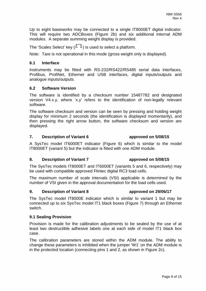
FIGURE S556 – 1
(a) SysTec Model IT9000E Digital Indicator (Pattern)
(b) SysTec Model ADCBox External Scale Multiplexer
NMI S556 Rev 4
Page 12 of 15
FIGURE S556 – 2
(a) Typical Sealing of Systec Model IT9000E Digital Indicator
(b) Typical Sealing of Systec Model ADCBox External Scale Multiplexer
(c) Showing Jumper W1 Sealing – Model IT9000E
Typical Sealing Methods
NMI S556 Rev 4
Page 13 of 15
FIGURE S556 – 3
(a) SysTec Model IT8000E Digital Indicator – Desk Mount Version (Variant 1)
(b) SysTec Model IT8000E Digital Indicator – Panel Mount Version (Variant 1)

NMI S556 Rev 4
Page 14 of 15
FIGURE S556 – 4
SysTec Model IT6000E Digital Indicator (Variant 2)
FIGURE S556 – 5
SysTec Model IT4000E Digital Indicator (Variant 3)
NMI S556 Rev 4
Page 15 of 15
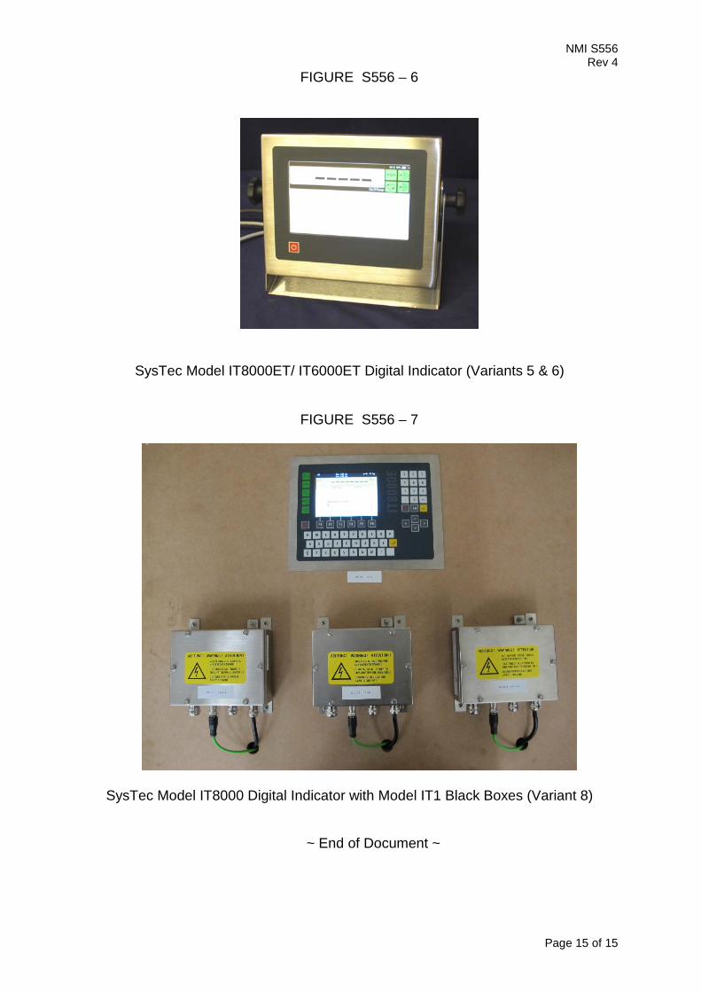
FIGURE S556 – 6
SysTec Model IT8000ET/ IT6000ET Digital Indicator (Variants 5 & 6)
FIGURE S556 – 7
SysTec Model IT8000 Digital Indicator with Model IT1 Black Boxes (Variant 8)
~ End of Document ~