supplementary material - computer sciencemaimone/media/focus3d_tog_2013_supplement.pdf ·...
TRANSCRIPT
Supplementary Material:Focus 3D: Compressive Accommodation Display
In this document we provide additional results and implementation details in support of the primary text. Appendix Apresents additional analysis of decomposed masks patterns and the results of a wide field of view display simula-tion. Appendix B provides details of the prototype display construction and pseudocode for the utilized GPU-basednonnegative tensor factorization (NTF) solver and supporting functions.
A Extended Results
A.1 Simulations of a Wide Tracked Field of View
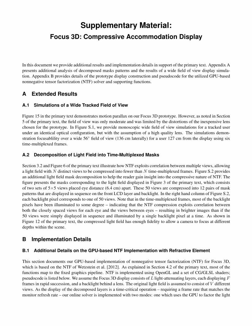
Figure 15 in the primary text demonstrates motion parallax on our Focus 3D prototype. However, as noted in Section5 of the primary text, the field of view was only moderate and was limited by the distortions of the inexpensive lenschosen for the prototype. In Figure S.1, we provide monoscopic wide field of view simulations for a tracked userunder an identical optical configuration, but with the assumption of a high quality lens. The simulations demon-stration focusablility over a wide 56◦ field of view (136 cm laterally) for a user 127 cm from the display using sixtime-multiplexed frames.
A.2 Decomposition of Light Field into Time-Multiplexed Masks
Section 3.2 and Figure 6 of the primary text illustrate how NTF exploits correlation between multiple views, allowinga light field with N distinct views to be compressed into fewer than N time-multiplexed frames. Figure S.2 providesan additional light field mask decomposition to help the reader gain insight into the compressive nature of NTF. Thefigure presents the masks corresponding to the light field displayed in Figure 3 of the primary text, which consistsof two sets of 5×5 views placed eye distance (6.4 cm) apart. These 50 views are compressed into 12 pairs of maskpatterns that are displayed in sequence on the front LCD layer and backlight. In the right hand column of Figure S.2,each backlight pixel corresponds to one of 50 views. Note that in the time-multiplexed frames, most of the backlightpixels have been illuminated to some degree – indicating that the NTF compression exploits correlation betweenboth the closely spaced views for each eye and the views between eyes – resulting in brighter images than if the50 views were simply displayed in sequence and illuminated by a single backlight pixel at a time. As shown inFigure 12 of the primary text, the compressed light field has enough fidelity to allow a camera to focus at differentdepths within the scene.
B Implementation Details
B.1 Additional Details on the GPU-based NTF Implementation with Refractive Element
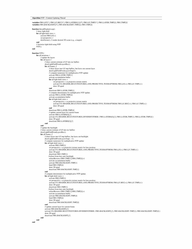
This section documents our GPU-based implementation of nonnegative tensor factorization (NTF) for Focus 3D,which is based on the NTF of Wetzstein et al. [2012]. As explained in Section 4.2 of the primary text, most of thefunctions map to the fixed graphics pipeline. NTF is implemented using OpenGL and a set of CG/GLSL shaders;pseudocode is listed below. We assume the Focus 3D display consists of L light-attenuating layers, each displaying Fframes in rapid succession, and a backlight behind a lens. The original light field is assumed to consist of V differentviews. As the display of the decomposed layers is a time-critical operation – requiring a frame rate that matches themonitor refresh rate – our online solver is implemented with two modes: one which uses the GPU to factor the light
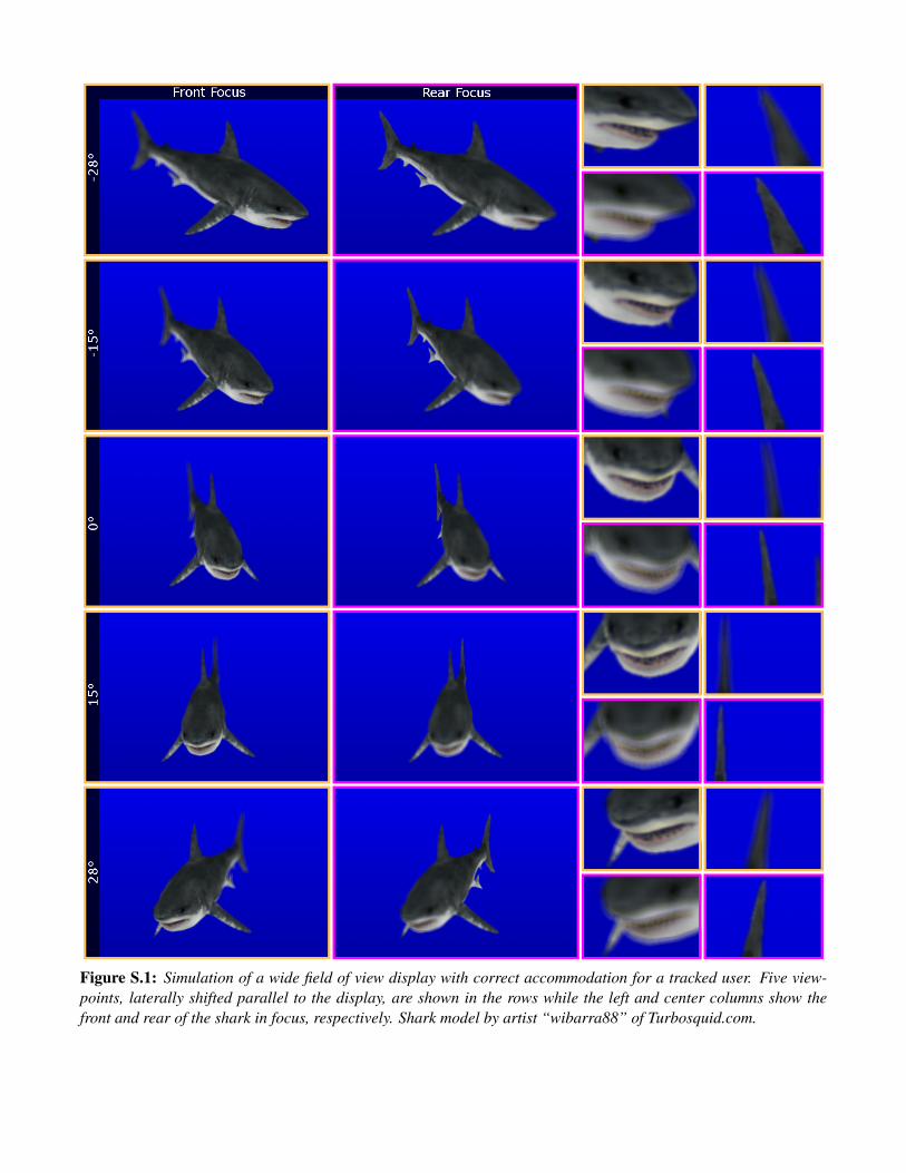
Figure S.1: Simulation of a wide field of view display with correct accommodation for a tracked user. Five view-points, laterally shifted parallel to the display, are shown in the rows while the left and center columns show thefront and rear of the shark in focus, respectively. Shark model by artist “wibarra88” of Turbosquid.com.
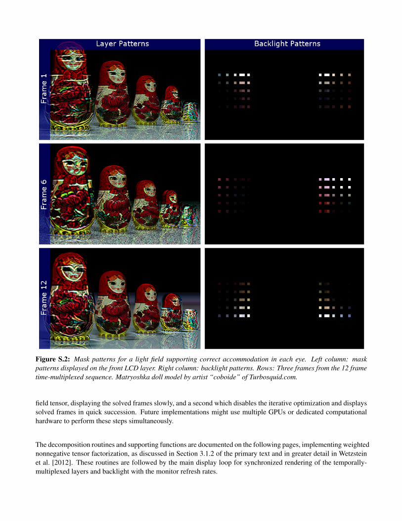
Figure S.2: Mask patterns for a light field supporting correct accommodation in each eye. Left column: maskpatterns displayed on the front LCD layer. Right column: backlight patterns. Rows: Three frames from the 12 frametime-multiplexed sequence. Matryoshka doll model by artist “coboide” of Turbosquid.com.
field tensor, displaying the solved frames slowly, and a second which disables the iterative optimization and displayssolved frames in quick succession. Future implementations might use multiple GPUs or dedicated computationalhardware to perform these steps simultaneously.
The decomposition routines and supporting functions are documented on the following pages, implementing weightednonnegative tensor factorization, as discussed in Section 3.1.2 of the primary text and in greater detail in Wetzsteinet al. [2012]. These routines are followed by the main display loop for synchronized rendering of the temporally-multiplexed layers and backlight with the monitor refresh rates.
Algorithm NTF - Content-Updating Thread
variables FBO LF[V ], FBO LF REC[V ], FBO LAYERS[L][F ], FBO LF TMP[V ], FBO LAYER TMP[2], FBO TMP[2]variables FBO BACKLIGHT[F ], FBO BACKLIGHT TMP[2], FBO TMP[2]
function threadDisplayLoop()// draw light fieldfor all light field views v
activate FBO LF[v]set perspective vdrawScene(); // render desired 3D scene (e.g., a teapot)
end// factorize light field using NTFNTF();
end
function NTF()for all iterations i
// update the layersfor all layers l
// draw current estimate of LF into rec buffersdrawLightFieldFromLayersRec();for all frames f
// draw layers into LF tmp buffers, but leave out current layerdrawLightFieldFromLayersTmp(l);// compute numerator for multiplicative NTF updateactivate FBO LAYER TMP[1]activate accumulation bufferfor all light field views v
set perspective v as projective texture matrixactivate CG SHADER MULT2TEXTURES AND PROJECTIVE TEXMAPTHEM( FBO LF[v], FBO LF TMP[v] )draw 2D quad
enddeactivate FBO LAYER TMP[1]// compute denominator for multiplicative NTF updateactivate FBO LAYER TMP[2]activate accumulation bufferfor all light field views v
set perspective v as projective texture matrixactivate CG SHADER MULT2TEXTURES AND PROJECTIVE TEXMAPTHEM( FBO LF REC[v], FBO LF TMP[v] )draw 2D quad
enddeactivate FBO LAYER TMP[2]// update current layer for current frameactivate FBO LAYERS[l][f ]activate CG SHADER MULT2TEXTURES DIVIDEBYOTHER ( FBO LAYERS[l][f ], FBO LAYER TMP[1], FBO LAYER TMP[2] )draw 2D quaddeactivate FBO LAYERS[l][f ]
endend// update the backlight// draw current estimate of LF into rec buffersdrawLightFieldFromLayersRec();for all frames f
// draw layers into LF tmp buffers, but leave out backlightdrawLightFieldFromLayersTmp(−1);// compute numerator for multiplicative NTF updatefor all light field views v
activate FBO TMP[1]set perspective v as projective texture matrix for lens positionactivate CG SHADER MULT2TEXTURES AND PROJECTIVE TEXMAPTHEM( FBO LF[v], FBO LF TMP[v] )draw 2D quaddeactivate FBO TMP[1]//refract from lens onto backlightrefractReverse (FBO TMP[1],FBO TMP[2],v)activate accumulation bufferactivate FBO BACKLIGHT TMP[1]bind FBO TMP[2]draw 2D quaddeactivate FBO BACKLIGHT TMP[1]
end// compute denominator for multiplicative NTF updatefor all light field views v
activate FBO TMP[1]set perspective v as projective texture matrix for lens positionactivate CG SHADER MULT2TEXTURES AND PROJECTIVE TEXMAPTHEM( FBO LF REC[v], FBO LF TMP[v] )draw 2D quaddeactivate FBO TMP[1]//refract from lens onto backlightrefractReverse (FBO TMP[1],FBO TMP[2],v)activate accumulation bufferactivate FBO BACKLIGHT TMP[2]bind FBO TMP[2]draw 2D quaddeactivate FBO BACKLIGHT TMP[2]
end// update current layer for current frameactivate FBO BACKLIGHT[f ]activate CG SHADER MULT2TEXTURES DIVIDEBYOTHER ( FBO BACKLIGHT[f ], FBO BACKLIGHT TMP[1], FBO BACKLIGHT TMP[2] )draw 2D quaddeactivate FBO BACKLIGHT[f ]
endend
end
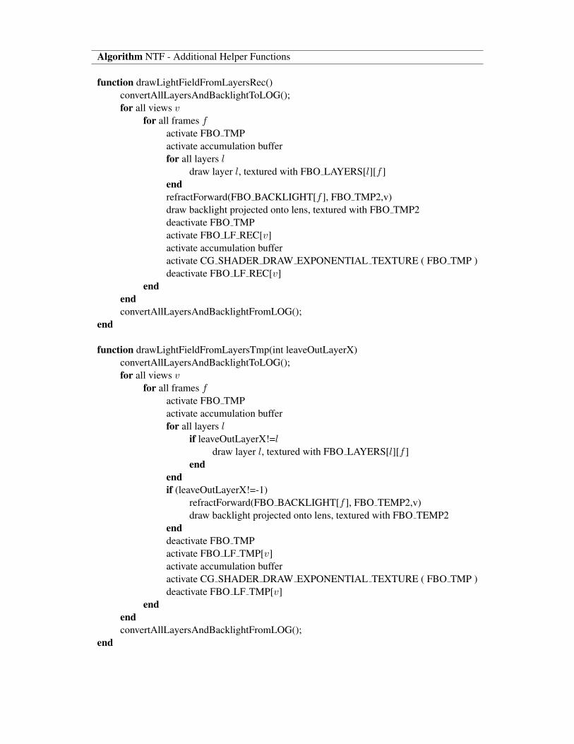
Algorithm NTF - Additional Helper Functions
function drawLightFieldFromLayersRec()convertAllLayersAndBacklightToLOG();for all views v
for all frames factivate FBO TMPactivate accumulation bufferfor all layers l
draw layer l, textured with FBO LAYERS[l][f ]endrefractForward(FBO BACKLIGHT[f ], FBO TMP2,v)draw backlight projected onto lens, textured with FBO TMP2deactivate FBO TMPactivate FBO LF REC[v]activate accumulation bufferactivate CG SHADER DRAW EXPONENTIAL TEXTURE ( FBO TMP )deactivate FBO LF REC[v]
endendconvertAllLayersAndBacklightFromLOG();
end
function drawLightFieldFromLayersTmp(int leaveOutLayerX)convertAllLayersAndBacklightToLOG();for all views v
for all frames factivate FBO TMPactivate accumulation bufferfor all layers l
if leaveOutLayerX!=ldraw layer l, textured with FBO LAYERS[l][f ]
endendif (leaveOutLayerX!=-1)
refractForward(FBO BACKLIGHT[f ], FBO TEMP2,v)draw backlight projected onto lens, textured with FBO TEMP2
enddeactivate FBO TMPactivate FBO LF TMP[v]activate accumulation bufferactivate CG SHADER DRAW EXPONENTIAL TEXTURE ( FBO TMP )deactivate FBO LF TMP[v]
endendconvertAllLayersAndBacklightFromLOG();
end
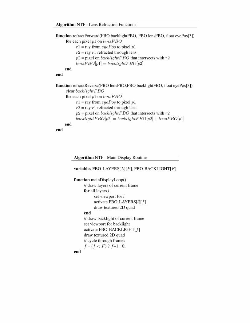
Algorithm NTF - Lens Refraction Functions
function refractForward(FBO backlightFBO, FBO lensFBO, float eyePos[3])for each pixel p1 on lensFBO
r1 = ray from eyePos to pixel p1r2 = ray r1 refracted through lensp2 = pixel on backlightFBO that intersects with r2lensFBO[p1] = backlightFBO[p2]
endend
function refractReverse(FBO lensFBO,FBO backlightFBO, float eyePos[3])clear backlightFBOfor each pixel p1 on lensFBO
r1 = ray from eyePos to pixel p1r2 = ray r1 refracted through lensp2 = pixel on backlightFBO that intersects with r2backlightFBO[p2] = backlightFBO[p2] + lensFBO[p1]
endend
Algorithm NTF - Main Display Routine
variables FBO LAYERS[L][F ], FBO BACKLIGHT[F ]
function mainDisplayLoop()// draw layers of current framefor all layers l
set viewport for lactivate FBO LAYERS[l][f ]draw textured 2D quad
end// draw backlight of current frameset viewport for backlightactivate FBO BACKLIGHT[f ]draw textured 2D quad// cycle through framesf = (f < F ) ? f+1 : 0;
end
B.2 Hardware
In this section we provide further details about the physical construction of the prototype Focus 3D display. Refer toFigure S.3 for imagery corresponding to the following description.
Our challenge is to align multiple light modulating layers (LCD panels) and a large Fresnel lens over a relativelylong distance. We use computer numerical control (CNC) machines to construct the parts required for our hardware.
After removing the LCD panels from their backlight units, we remove the diffusing polarizing film from the front ofeach panel, making the LCD suitable for image formation. Acetone is used to remove residual adhesive left on thesurface of the panel. A transparent polarizing film is then secured in place of the removed polarizing film to restorethe intensity modulation capability of the panel.
The LCD panels are mounted on waterjet cut aluminum back planes. We similarly mount the Fresnel lens insidean acrylic sheet, cut to fit on a lasercutter. Each of these layers is placed on a rail cage and accurately spaced usinglasercut plastic clips. Our rail cage is assembled from waterjet cut 3
8” aluminum posts, fitted to a wooden base cut tosize on a ShopBot CNC mill. Machined alignment holes are then match drilled to ensure the posts and layers slidesmoothly on 1
4” steel rails.
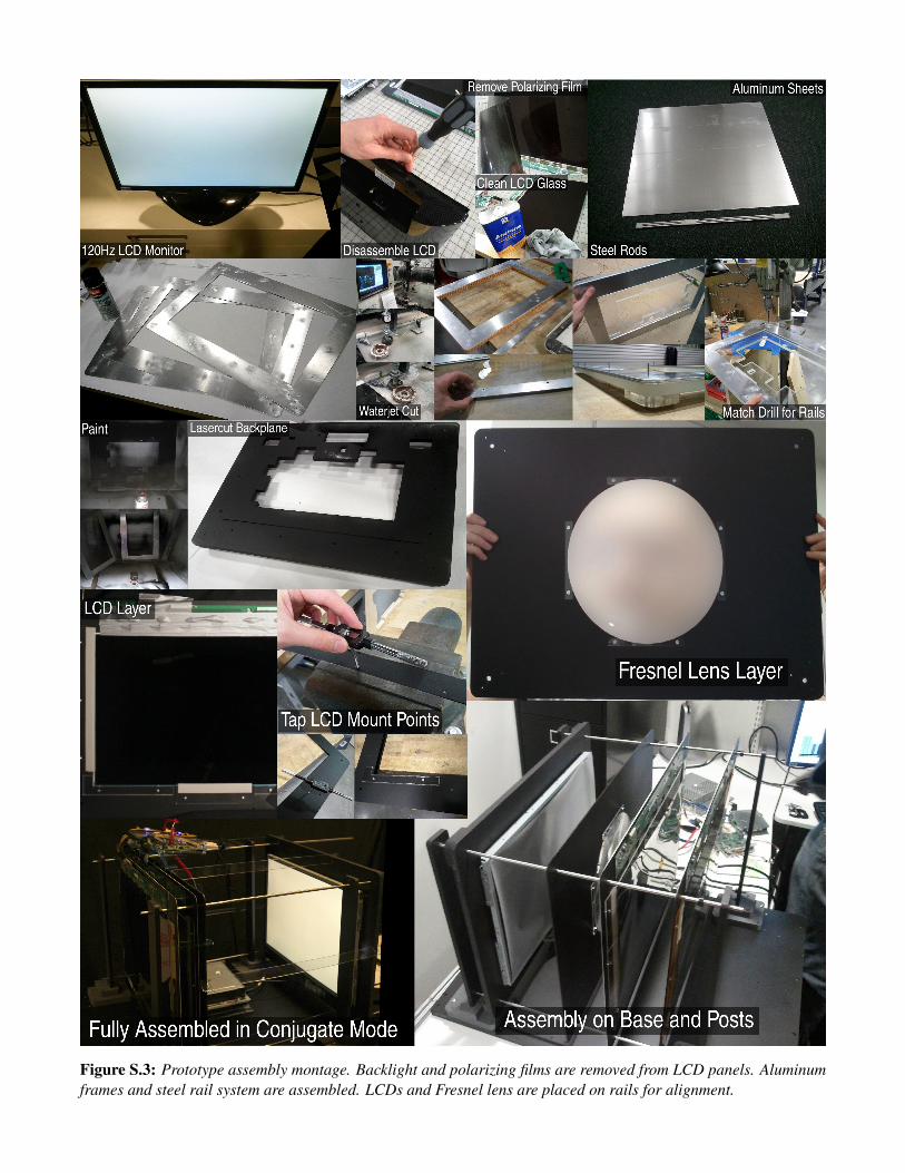
Figure S.3: Prototype assembly montage. Backlight and polarizing films are removed from LCD panels. Aluminumframes and steel rail system are assembled. LCDs and Fresnel lens are placed on rails for alignment.

Supplementary References
WETZSTEIN, G., LANMAN, D., HIRSCH, M., AND RASKAR, R. 2012. Tensor Displays: Compressive Light FieldSynthesis using Multilayer Displays with Directional Backlighting. ACM Trans. Graph. (SIGGRAPH) 31, 1–11.