support in underground hard rock mines
TRANSCRIPT

SUPPORT IN UNDERGROUND HARD ROCK MINES
Evert Hoek, NSERC Industrial Research Professor, Department of Civil Engineering,University of Toronto, Toronto, Canada.
David. F. Wood, Senior Engineer, Golder Associates, Vancouver, British Columbia,Canada
Published in Underground Support Systems.Edited by J. Udd. (Montreal; Canadian Institute of Mining and Metallurgy). Special
Volume 35, 1987, pages 1-6.

Support in Hard rock Underground Mines
2
Introduction
Rock support is the term widely used to describe the procedures and materials used toimprove the stability and maintain the load bearing capacity of rock near to theboundaries of an underground excavation. In this paper, a distinction is drawnbetween rock reinforcement or active support, where the supporting elements are anintegral part of the reinforced rock mass, and rock support or passive support, wherethe supporting members are external to the rock and respond to inward movement ofthe rock surrounding the excavation. A good example of active reinforcement is apattern of untensioned grouted dowels which are tensioned as the rock deforms andwhich interact with the rock in much the same way as reinforcing steel does withconcrete. Steel sets are an example of passive support since they external to the rockmass and can only respond to progressive inward movement of the loosened rockmass.
The primary objective of a support system is to mobilize and conserve the inherentstrength of the rock mass so that it becomes self-supporting. Rock support generallycombines the effects of reinforcement, by such elements as dowels, tensioned rockbolts and cables, and support, with shotcrete, mesh and steel sets which carry loadsfrom individual rock blocks isolated by structural discontinuities or zones of loosenedrock. These notes are intended to assist the underground support engineer in choosingthe most appropriate, and the easiest to install, combination of reinforcement andsupport. If possible, the installation of rock support should be carried out as anintegral part of the excavation cycle to enhance the self -supporting aspects of rockmass improvement.
Rock support
The choice of the type of support installed in a particular underground excavationdepends upon the extent of the zone of loosened or fractured rock surrounding thatexcavation. A very crude guide to support selection is given in Table 1.
Active rock reinforcement
Underground mines use two principal types of rock reinforcement - tensionedmechanically anchored rockbolts and untensioned grouted or friction anchoreddowels. It is important that the different ways in which these reinforcing systemswork is fully understood and a brief discussion on this subject is given on the pageswhich follow.
Mechanically anchored rockbolts
Mechanically anchored rockbolts are probably the oldest form of rock reinforcementused in underground mining and are still the most common form of rockreinforcement used in Canadian mines. Provided that the rock is hard enough toprovide a good grip for the anchor, an expansion shell anchor which is well seatedwill usually allow a rockbolt to be tensioned to its maximum load-carrying capacity.In fact, if a bolt is overloaded, it usually fails in the threads at either the faceplate oranchor end rather than by anchor slip.

Support in Hard rock Underground Mines
3
Tensioned rockbolts are most effective in retaining loose blocks or wedges of rocknear the surface of the excavation. These blocks may have been loosened byintersecting joints and bedding planes in the rock or they may have been created bypoor quality blasting. In either case, falls of loose rock create unsafe workingconditions and some form of support is required.
Since the amount of loosening does not usually penetrate very far into the rock mass,the support is only required to hold up the dead weight of the loose material.Mechanically anchored rockbolts, with the addition of mesh where small pieces ofrock are likely to fall out between bolt heads, provide very effective support for theseconditions. Tensioning of the bolts, usually to about 70% of their ultimate breakingload, is required in order to tighten the loose blocks and wedges and to provide asmuch interlocking between these blocks as possible. It is by helping the rock tosupport itself and by the prevention of further unravelling and deterioration of therock mass that the tensioned rockbolts provide effective support.
Unfortunately, mechanically anchored rockbolts suffer from several problems. Thereis a tendency for anchors to slip progressively with time, probably as a result ofvibrations induced by nearby blasting. Hence, old rockbolts which have clearly lost alltheir tension are frequently seen in underground mines. Another problem relates torusting of the bolts in rock masses with aggressive groundwater, for example, inmassive sulphides. Sometimes, the life of an unprotected bolt may be less than oneyear under such circumstances and, where long term life is required, the bolts shouldbe grouted in place.
The need for mechanically anchored rockbolts is reduced significantly by carefulblasting and by correct scaling. These techniques reduce the amount of loose rockwhich has to be supported and hence the need for bolts and mesh.
Grouted or friction anchored dowels
One of the main disadvantages of mechanically anchored rockbolts is that, if theanchor slips or the bolt breaks, the capacity of the bolt drops to zero and the rockbeing supported can fall. This problem is less severe in the case of a fully grouted orfriction anchored dowel because, even if slip does occur or if the face plate breaks off,the remaining length of the dowel is still anchored and will continue to providesupport.
The problem with grouted or friction anchored dowels is that they cannot be tensionedand hence they have to be installed before significant movement has taken place in therock. In fact, experience has shown that this apparent problem can be turned toadvantage and that a combination of careful blasting and the installation of dowels asclose as possible to the advancing face can provide very effective support for a muchwider range of rock conditions than can be handled by mechanically anchored bolts.The installation of the dowels close to the advancing face ensures that relatively littlemovement has taken place in the rock mass and that the maximum amount ofinterlocking between individual pieces is retained. Retention of this interlocking iscritical to the self-supporting characteristics of the rock mass and any loss of interlockcauses a very severe drop in strength.

Support in Hard rock Underground Mines
4
Table 1: Suggested support for various rock conditions.
Rock Conditions Suggested support typeSound rock withsmooth walls createdby good blasting.Low in situ stresses.
No support or alternatively, where required for safety, mesh held in place bygrouted dowels or mechanically anchored rockbolts, installed to prevent smallpieces from falling.
Sound rock with fewintersecting joints orbedding planesresulting in loosewedges or blocks.Low in situ stresses.
Scale well then install tensioned, mechanically anchored bolts to tie blocks intosurrounding rock. Use straps across bedding planes or joints to prevent smallpieces falling out between bolts. In permanent openings, such as shaft stationsor crusher chambers, rockbolt should be grouted with cement to preventcorrosion.
Sound rock damagedby blasting with afew intersectingplanes. Low in situstresses
Chain link or weld mesh held by tensioned mechanically anchored rockbolts, toprevent falls of loose rock. Attention must be paid to scaling and to improvingblasting to reduce amount of loose rock.
Closely jointedblocky rock withsmall blocksravelling fromsurface causingdeterioration ifunsupported. Lowstress conditions.
Shotcrete layer, approximately 50 mm thick. Addition of micro-silica and steelfibre reduces rebound and increases strength of shotcrete in bending. Largerwedges are bolted so that shotcrete is not overloaded. Limit scaling to controlravelling. If shotcrete not available, use chain-link or weldmesh and patternreinforcement such as split sets or Swellex.
Stress-inducedfailure in jointedrock. Firstindication of failuredue to high stressesare seen in boreholewalls and in pillarcorners.
Pattern support with grouted dowels or Swellex. Split sets are suitable forsupporting small amounts of failure. Grouted tensioned or untensioned cablescan be used but mechanically anchored rockbolts are less suitable for thisapplication. Typical length of reinforcement should be about ½ the span ofopenings less than 6 m and between ½ and 1/3 for spans of 6 to 12 m. Spacingshould be approximately ½ the dowel length. Support should be installedbefore significant movement occurs. Shotcrete can add significant strength torock and should be used in long-term openings (ramps etc.). Mesh and strapsmay be required in short-term openings (drill-drives etc.)
Drawpointsdeveloped in goodrock but subjected tohigh stress and wearduring blasting anddrawing of stopes.
Use grouted rebar for wear resistance and for support of drawpoint brows.Install this reinforcement during development of the trough drive anddrawpoint, before rock movement takes place as a result of drawing of stopes.Do not use shotcrete or mesh in drawpoints – place dowels at close spacing inblocky rock.
Fractured rockaround openings instressed rock with apotential forrockbursts
Pattern support required but in this case some ‘flexibility’ required to absorbshock from rockbursts. Split sets are good since they will slip under shockloading but will retain some load and keep mesh in place. Grouted dowels andSwellex will also slip under high load but some face plates may fail.Mechanically anchored bolts are poor in these conditions. Lacing betweenheads of reinforcement helps to retain rock near surface under heavyrockbursting.
Very poor rockassociated withfaults or shear zones.Rock-bolts ordowels cannot beanchored in thismaterial.
Fibre-reinforced shotcrete can be used for permanent support under low stressconditions or for temporary support to allow steel sets to be placed. Note thatshotcrete layer must be drained to prevent build up of pressure behind theshotcrete. Steel sets are required for long-term support where it is evident thatstresses are high or that roc is continuing to move. Capacity of steel setsestimated from amount of loose rock to be supported.

Support in Hard rock Underground Mines
5
With the development of grouted or friction anchored dowels which are botheconomical and simple to install, the use of untensioned dowels has become verywide-spread in mining and will probably become the dominant rock reinforcementtechnique in years to come.
Grouted cables
Rockbolts and dowels can be replaced in most mining applications by means ofgrouted cables. The main advantage of these cables is that they can be installed inopenings with very low headroom. The cables can be grouted in place withouttensioning or they can be tensioned before grouting. In recent years, simple tensioningtechniques have been developed which eliminate the complex and time-consumingprocedures previously used.
Grouted cables are very effective in applications such as the reinforcement of ore orwaste passes. The progressive wear of the exposed cable does not reduce the supportprovided by the remaining length of grouted cable. The flexibility of the cables allowsthe rock mass to ‘work’ without a significant loss of strength.
In cut and fill mining, long grouted cables can be pre-placed in the ore-body to bemined in order to provide support for the stope backs. As the cables are shortened byprogressive cuts, the remaining grouted lengths are tensioned by downwardmovement of the rock above the stopes and support forces are generated. When theremaining length of cable has been reduced to about 2m, a new set of cables isinstalled to overlap the first set and to assume the support duties when the first set ismined out.
When a large zone of potentially unstable rock is to be supported, say adjacent to afault or shear zone, long tensioned and grouted cables can be installed fromdevelopment headings before mining of the stopes takes place. Long grouted cableshave also been used successfully in many civil engineering applications such as theanchoring of crane beams in large underground powerhouse excavations or thesupport of very large span openings where normal rockbolts would have provedinadequate.
Passive rock support
In order to complement the reinforcement achieved using dowels, bolts or cables, rocksupport often includes the use of mesh, straps, shotcrete or steel sets. Each of theserock support elements is reviewed briefly in the notes which follow.
Mesh
A general rule which can be used deciding upon the spacing of rockbolts is that thedistance between faceplates should be approximately equal to three times the averagespacing of the weakness planes in the rock mass. Hence, if a set of intersecting jointsand bedding planes create wedges or blocks with an average side length of 0.5m, theideal bolt spacing should be about 1.5m and the bolt length should be twice the boltspacing, i.e 3m. This example gives reasonable bolt lengths and spacing but, what is

Support in Hard rock Underground Mines
6
the solution if the average joint spacing is about 100mm? Obviously, it would beimpractical to place bolts at 300mm centres and, under these circumstances, mesh isused to keep the small blocks between the faceplates in place.
Mesh may be either chainlink or weldmesh. Chainlink mesh is flexible and has a veryhigh load bearing capacity. It is, however, rather difficult to handle during installationand it is also completely unsuitable for use with shotcrete because of the difficulty ofeliminating the air pockets trapped behind the links in the mesh. Weldmesh,fabricated by welding a grid of crossing wires at their intersection points, is morerigid and is easier to install than chainlink mesh. It is also suitable for use withshotcrete because the wire intersections are small in area and it is easy for theshotcrete to penetrate behind these intersections.
Straps
When the rock mass surrounding an underground opening is very slabby, in otherwords, most of the weakness planes run in one direction, the strength of the rock massis much higher in the direction of the weakness planes than it is across these planes.Under these circumstances, straps may be a more effective means of face support thanmesh. These straps are placed between rockbolts and run across the planes ofweakness. Straps placed parallel to the planes of weakness are generally a waste ofmoney.
Shotcrete
Shotcrete is used very widely in civil engineering construction but is not used by themining industry to the extent that it deserves. This is partly due to the fact that atypical mine has many working faces and it is difficult to schedule the shotcretingequipment efficiently. It is also due to traditional attitudes which are graduallychanging in recognition of the fact the each element in underground support plays adifferent role and that shotcrete can be a very effective support medium. The shotcreteacts in much the same was as mesh in that it prevents small pieces of rock fromunravelling from the surface of an excavation. This helps to retain the interlockingand self-supporting characteristics of the rock mass. Since shotcrete is generallystronger than mesh, particularly if it is fibre-reinforced, and since it is corrosionresistant, it is generally considered to be a more effective support system. It isparticularly useful in excavations such as ramps and haulages where long-termstability is important.
Shotcrete has developed into a versatile support system with the addition of micro-silica and steel fibre reinforcement to the mortar/aggregate mix. The complexinstallation of thin layers of shotcrete, reinforced with weldmesh fabric can now bereplaced quickly and economically by a single pass of steel fibre reinforced micro-silica shotcrete. Sufficient research has now gone into shotcrete mix design and theconstituent materials used, that shotcrete quality now rests almost entirely with theequipment operators. Shotcrete application requires constant attention to the supplypressure and volume of water, mix and air to ensure that the material leaves the nozzlein a continuous uninterrupted stream which can be applied by the nozzleman in such afashion as to maximize compaction and quality while minimizing rebound andoverspray.

Support in Hard rock Underground Mines
7
As shotcrete develops strength with time after application, it may be used effectivelysoon after excavation. Local readjustment of the in situ stress field due to mining isunlikely to induce excessive loading on the green shotcrete, and shotcrete has showngood resilience and durability to nearby blasting. As loading is transferred on to thesupport system, it is gaining strength and producing a stiffening support member.Most products are shot with up to 5% accelerator if a high early strength is required.This obviously leads to the development of a faster supporting member, but care mustbe exercised in design to ensure that the support will not become overstressed by loadtransferred from relaxing ground in high stress environments.
The use of a micro-silica additive means that rebound is reduced considerably,thickness of application can be increased, weak zones of rock with running water canbe covered and voids can be filled effectively. Silica does not appear to affect the longterm strength of the product.
The addition of high aspect ratio, deformed steel fibres, usually 30-38 mm long and0.5 mm in equivalent diameter, enhances the post crack load bearing capacity of thesupport system, although it does not give a marked improvement to the initial bendingstrength of the shotcrete layer. Early problems with balling of steel fibres andexcessive equipment wear have been largely overcome and the addition of steel fibresdo not usually give rise to significant operational problem.
Typical shotcrete mix design
Components kg/cu.m Percent
Cement 420 18.6Micro-silica additive 42 1.9Blended aggregate 1735 76.9Steel fibres 59 2.9
Steel sets
Steel sets have generally replaced timber as the traditional ‘passive’ support system inunderground construction. The term ‘passive’ derives from the fact that the steel sets(or timber) do not interact with the rock in the same way as rockbolts or dowels.These elements become part of the rock mass in much the same way as reinforcingbecomes part of the concrete in reinforced concrete. On the other hand, passivesupport such as steel sets can only respond to loads imposed on them by the inwardmovement of the rock. Since they are generally placed some distance behind theadvancing face, most of the short-term movement in the rock has already taken placebefore the sets are in place and the only load which they are called upon to carry is thedead-weight of rock failing around the opening.
In hard rock mining, steel sets have very limited application since most support dutiescan be performed more effectively by rockbolts, dowels or shotcrete or by somecombination of these systems. The exception is in mining through faults or in verybadly broken ground associated with faults of shear zones. In such cases, it may beimpossible to anchor the rockbolts or dowels in the rock mass and steel sets may berequired in order to carry the dead weight of the failed material surrounding the

Support in Hard rock Underground Mines
8
opening.
Blocking is a critical part of steel set installation since it is essential that the rockloads be transferred uniformly onto the steel sets. Badly blocked sets are a very poorinvestment. Traditionally, wood is used as a blocking medium and this can be veryeffective if carefully placed and tightly wedged in place. In some mining applications,where large rock movements are anticipated, timber poles placed parallel to theopening axis are used to distribute the load onto the sets. These poles act rather likeroller bearings and move with the rock to give a uniform load distribution on the sets.Where wood is difficult to obtain or where a skilled labour force is not available toinstall timber blocking correctly, timber blocking can be replaced by means of sacksof lean concrete. These sacks are pushed into place behind the sets and then sprayedwith water to initiate setting of the concrete. The weak concrete provides adequateblocking to transfer the rock loads uniformly onto the steel sets.
Illustrations of support systems
Illustrations of different support systems are presented on the pages which follow.These illustrations are intended to provide a condensed summary of the mostimportant features of each system and to act as simple design aids to rock supportdesigners and users.
Warning: Some of the systems or components illustrated in this series of drawings areprotected by patents. Potential users intending to manufacture similar systems orcomponents should check patent regulations.
1. Mechanically anchored, tensioned rockbolt
Background:Figure 1 illustrates a number of components which can be used in differentcombinations. The expansion shell anchor is one of a large number of different types,all of which operate in basically the same way. A wedge, attached to the bolt shank ispulled into a conical anchor shell forcing it to expand against the drillhole walls.When grouting a bolt, the rubber grout seal is used to centre the bolt in the hole and toseal the collar of the hole against grout leakage. An alternative system is to use aquick setting plaster to seal the hole collar. The grout is injected into the collar end ofthe hole (except in down-holes) and the return pipe is extended for the length of thehole. Grout injection is stopped when the air has been displaced and grout flows fromthe return tube.
Advantages:Bolt can be tensioned immediately after installation using an impact wrench, torquewrench or hydraulic jack, and grouted at a later stage when short term movementshave ceased. This system provides very reliable anchorage in good rock and high boltloads can be achieved.
Disadvantages:Correct installation requires skilled workmen and close supervision. Grout tubes areoften damaged during installation.

Support in Hard rock Underground Mines
9
Applications:These bolts are very widely used for permanent support applications in civilengineering. Mechanically anchored bolts without grout are widely used in mining.
Typical data:Steel designation ASTM A 615 (Grade 60) or ASTM A 722 (Grade 150)Yield stress 414 MPa (60000 psi) or 1034 MPa (150000 psi)Steel diameter 19 mm ( 4
3 ”) to 35 mm (1 83 ”)
Hole diameter 41 mm (1 85 ”) to 63 mm (2 ½”)
Length variable
Figure 1. Mechanically anchored, tensioned rockbolt
2. Untensioned grouted dowel
Background:Developed as an inexpensive solution where use of untensioned dowels is appropriate.A thick grout is pumped into the drillhole by means of a simple hand pump or amonopump. The dowel is pushed into the grout as shown in Figure 2. For up-holes,the dowel is sometimes held in place by bending the dowel slightly during insertion.A faceplate and nut can be added if required although, for light support, a plain dowelis sometimes used. Resin cartridges can also be used to encapsulate the bar andprovide bonding to the rock.
Advantages:Simple and inexpensive. High corrosion resistance in permanent installations.
Disadvantages:Cannot be tensioned and hence must be installed before significant deformation of therock mass has taken place. Care must be taken to ensure resin ‘grout’ is properly

Support in Hard rock Underground Mines
10
mixed. Resin has limited shelf life.
Applications:Widely used in the mining industry for general support duties.
Typical data:Steel designation ASTM A 615 (Grade 60)Yield stress 414 MPa (60000 psi)Steel diameter 19 mm ( 4
3 ”) to 25 mm (1”)Hole diameter 35 (1 8
3 ” ) to 38 mm (1 ½”)Length variable
Figure 2. Untensioned, grouted dowel
3. Friction anchored rockbolt - Swellex
Background:Developed by Atlas Copco AB, the Swellex deformed tube is expanded by waterpressure to the the shape of the drill hole. Mechanical interlock of the bolt and therock then prevents the bolt from sliding. Expansion of the deformed tube leads tosome reduction in length, which puts the Swellex into tension.
Advantages:Rapid and simple installation. Gives immediate support action after installation. Canbe used in a variety of ground conditions. The installation causes contraction in thebolt length. This effectively tensions the face plate against the rock surface.
Disadvantages:Corrosion can be a problem in long term installations. Requires a pump forinstallation. May require a sleeve at the collar to prevent spalling under certain rockconditions.

Support in Hard rock Underground Mines
11
Applications:Swellex bolts are commonly used in the mining industry for medium-term supportrequirements. Becoming increasingly used in civil engineering tunneling work.
Typical data:Yield load 130 kN (13 ton f)Tube diameter 26 mm (1”)Hole diameter 33 mm (1 8
3 ”) to 39 mm (1 ½”)Lengths Up to 8 m (24ft)Inflation pressure 20 MPa (3000psi)
Warning: Swellex bolts are patented by Atlas Copco AB, Sweden.
Figure 3. Friction anchored rockbolt – Swellex
4. Friction anchor or Split Set
Background:Developed by Scott in conjunction with the Ingersoll -Rand Company in the U.S.A.,this device has gained considerable popularity in the mining industry. As the split tubeis forced into a drillhole, the spring action of the compressed tube applies a radialforce against the rock and generates a frictional resistance to sliding of the rock on thesteel. This frictional resistance increases as the outer surface of the tube rusts.

Support in Hard rock Underground Mines
12
Advantages:Simple and quick to install and claimed to be cheaper than a grouted dowel of similarcapacity. Useful in moving and bursting ground.
Disadvantages:Cannot be tensioned and hence is activated by movement in the rock in the same wayas a grouted dowel. Its support action is similar to that of an untensioned dowel andhence it must be installed very close to the face. The drillhole diameter is critical andmost failures during installation occur because the hole is either too small or too large.In some applications, rusting has occurred very rapidly and has proved to be aproblem where long term support is required. The device cannot be grouted.
Applications:Used for relatively light support duties in the mining industry, particularly whereshort term support is required. Little application in civil engineering at present.
Typical data:Yield load 90 kNTube diameter 33 mm (1.32”), 39 mm (1.55”) and 46 mm (1.81”)Hole diameter 32 mm (1 8
1 ”), 35 mm (1 83 ”) and 41 mm (1 8
5 ”)Lengths: variable
Warning: Split Set friction rock stabilizers are patented by the Ingersoll-RandCompany, U.S.A.
Figure 4. Friction anchor or Split Set

Support in Hard rock Underground Mines
13
5. Resin grouted, tensioned threaded bar
Background:The most sophisticated rockbolt system currently in use, combines most of theadvantages of other bolt systems. Resin and a catalyst are contained in plastic‘sausages’, the catalyst being separated in a glass or plastic container in the resin.These capsules are pushed into the hole with a loading stick and the bar is theninserted. Rotation of the bar during insertion breaks the plastic containers and mixesthe resin and catalyst. The bar illustrated in Figure 5 has a very coarse rolled threadwhich gives good bonding and allows the length of the installation to be adjusted veryeasily.
Advantages:This system is very convenient and simple to use. Very high strength anchors can beformed in rock of poor quality and, by choosing appropriate setting times, a ‘one shot’installation produces a fully grouted tensioned rockbolt system.
Disadvantages:Effective resin mixing requires careful adherence to recommendations provided bymanufacturers. Resins are expensive and many have a limited shelf-life, particularlyin hot climates.
Applications:Increasingly used in critical applications in which cost is less important than speedand reliability.
Typical data:As for mechanically anchored rockbolts.
Figure 5. Resin grouted, tension threaded bar

Support in Hard rock Underground Mines
14
6. Grouted Cable Bolt
Background:Grouted cables were introduced to mining for reinforcement of the backs of cut andfill stopes. Cable reinforcement, using tensioned or untensioned, fully grouted cables,is very widely used in mining applications. Cables can be installed effectively in verynarrow tunnels, they are inexpensive and have a very high load bearing capacity.
Advantages:This system is inexpensive. If properly installed, it provides competent and durablereinforcement. It can be installed to any length in narrow areas. The system gives veryhigh bolt loads in various rock conditions, as well as high corrosion resistance inpermanent installations.
Disadvantages:Tensioning of the cable bolt is possible only if a special installation procedure isadopted. The use of standard cement in the grout requires several days curing beforethe cable can be loaded.
Applications:The system is gaining increasing use in mining applications.
Typical data:Yield stress 1770 Mpa (257000 psi)Yield load 500 kN (50 ton f)Cable diameter 20 mm ( 32
25 ”)Hole diameter 35 mm (1 8
3 ”)Lengths: Any length required
Figure 6. Grouted cable bolt

Support in Hard rock Underground Mines
15
7. Strap
Background:This system is used extensively in mining and civil engineering applications to holdslabby ground between rock bolts or to prevent slabs from loosening.
Advantages:Straps are easy to install with rock bolts. They are very effective in stratified, slabbyground.
Disadvantages:Straps cannot be used to control ravelling in loose, blocky ground if the block size issmall.
Applications:Steel straps are used to give roof control in ground where rockbolts or dowels alonecannot hold intermediate and relatively thin slabs of rock. The strap is formed tofollow the rock surface and held with regular rock reinforcement or specially installedpins. Straps should always be installed across weakness planes.
Figure 7. Strap
8. Mesh
Background:Wire mesh is used to support small pieces of loose rock and broken rock from falling.Two types of wire mesh currently used in underground operations are chainlink meshand weld mesh.
Advantages:Mesh is very economical and quickly installed. It is easy to attach to roof

Support in Hard rock Underground Mines
16
reinforcement with extra faceplates and nuts. It is easily repaired.
Disadvantages:Mesh cannot carry excessive load of broken rock without failure. It is easily damagedby flyrock from nearby blasts.
Applications:Mesh is useful for supporting small pieces of broken rock. Weldmesh is usedtraditionally as reinforcement for shotcrete, but is rapidly being replaced by steel fibrereinforced shotcrete. Mesh, like straps, is held in place with additional faceplates orwashers and nuts on rockbolts or using separate pins.
Figure 8. Mesh
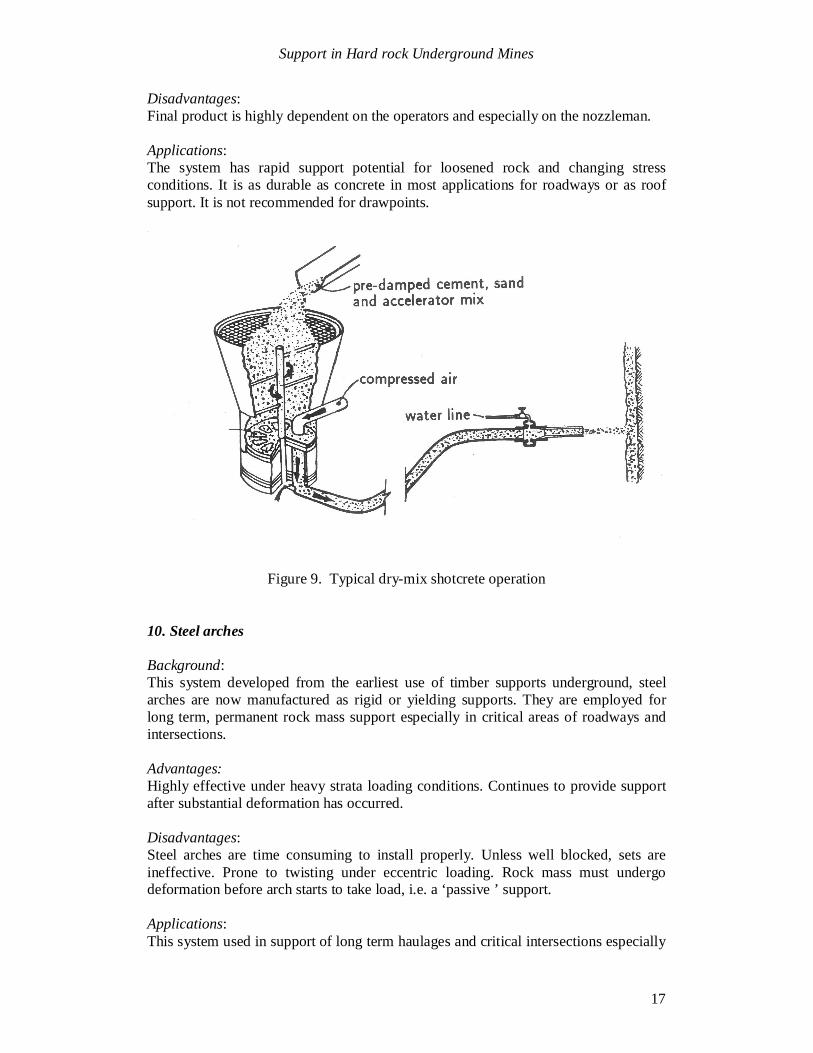
9. Typical dry-mix shotcrete operation
Background:Pneumatically applied mortar and concrete have been used increasingly in the supportof underground excavations both in civil and mining applications. Two basic types ofshotcrete (dry-mix and wet-mix) can be used. Flexibility of equipment, batching andavailability often result in the use of the dry-mix process in mining.
Advantages:This system is very adaptable to the tunneling environment. New technology hasmade mix design easier.
Support in Hard rock Underground Mines
17
Disadvantages:Final product is highly dependent on the operators and especially on the nozzleman.
Applications:The system has rapid support potential for loosened rock and changing stressconditions. It is as durable as concrete in most applications for roadways or as roofsupport. It is not recommended for drawpoints.
Figure 9. Typical dry-mix shotcrete operation
10. Steel arches
Background:This system developed from the earliest use of timber supports underground, steelarches are now manufactured as rigid or yielding supports. They are employed forlong term, permanent rock mass support especially in critical areas of roadways andintersections.
Advantages:Highly effective under heavy strata loading conditions. Continues to provide supportafter substantial deformation has occurred.
Disadvantages:Steel arches are time consuming to install properly. Unless well blocked, sets areineffective. Prone to twisting under eccentric loading. Rock mass must undergodeformation before arch starts to take load, i.e. a ‘passive ’ support.
Applications:This system used in support of long term haulages and critical intersections especially

Support in Hard rock Underground Mines
18
in highly stressed ground. Yielding and rigid supports are required in differentapplications.
Figure 10. Steel arches
Acknowledgements
This paper is based upon a report originally prepared for Cominco’s Sullivan mineand the permission granted by Cominco for publication of this paper is gratefullyacknowledged. The authors wish to thank Mr Byron Stewart and Mr Roy van Rijswykfor the constructive criticism provided during the preparation of this paper.