supporting information - national university of singapore
TRANSCRIPT

Copyright WILEY‐VCH Verlag GmbH & Co. KGaA, 69469 Weinheim, Germany, 2014.
Supporting Information
for Adv. Mater., DOI: 10.1002/adma.201405047
Ultrathin Pancharatnam-Berry Metasurface with Maximal Cross-Polarization Efficiency Xumin Ding, Francesco Monticone, Kuang Zhang,* Lei Zhang, Dongliang Gao, Shah Nawaz Burokur, Andre de Lustrac, Qun Wu, Cheng-Wei Qiu,* and Andrea Alù*

Supplementary Information
Ultra-thin Metasurfaces with Maximal Cross-polarization
Efficiency 1. Details of the miniaturized aperture geometry
In the microwave range, metals can be treated as perfect electric conductors (PEC), and the
interface of metal and dielectric materials usually does not support surface plasmon waves,
which represents an important difference compared to metalenses at optical frequencies.
However, it has been shown that spoof surface plasmons can be excited on structured metallic
surfaces,[S1] and localized resonances of rectangular slots can support extraordinary optical
transmission (EOT).[S2]
When a localized mode is excited, a strong polarization-dependent resonance can be
induced. In arrays, these localized resonances have been shown to be almost independent of
the periodicity of the unit cell and the thickness of the PEC film on which the apertures are
carved,[S2] opening interesting possibilities for the control of the phase response and the
realization of ultra-thin metalenses in the microwave range.
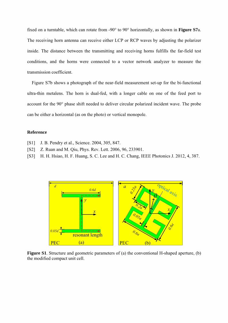
In Reference [S3], the EOT phenomenon for apertures composed of two horizontal arms
connected by one vertical arm was studied in detail. One of these apertures is shown in
Figure S1a. The operating wavelength of the localized resonances in this case can be
estimated by the modified cutoff wavelength of the rectangular waveguide: λres=2neffLres/m,
where 2 2 2eff sub airn n n is the effective refractive index (nsub and nair are the refractive
indices of the substrate and air, respectively), m is an integer, and Lres is the resonant length
shown in Figure S1a as the red line. This implies that only the effective refraction index of the
substrate affects the resonance frequency, while the thickness has no effects on the resonances.

In the present paper, an aperture with miniaturized size has been introduced as shown in
Figure S1b. The horizontal arms have been folded to achieve a more compact resonance.
Simulations show that, in order to get the same first-order resonance frequency, the side
length a of the modified unit cell (Figure S1b) has been reduced by about 50% compared with
the side length d of the original geometry (Figure S1a). Therefore, more unit cells with the
proposed structure may be placed in the same super cell, improving the spatial resolution of
phase control, and the phase distribution generated can be more uniform. The aperture was
fabricated over a metallic slab and has a very small thickness (0.035mm, about 0.001λ for
10GHz). A dielectric substrate, with permittivity of 3.5 and thickness of 0.1 wavelength, is
introduced to fulfill the mechanical requirements for fabrication and testing. The geometric
parameters of the aperture are shown in Figure S1b in detail. The first resonance mode, with
m=1, occurs when the incident wave is x-polarized, and the resonant length Lres is twice for y-
polarized incident waves at the second resonance mode. From Figure 1c in the main text, we
see that the first resonance mode occurs at 9.8 GHz, as simulated. Instead, without the
substrate, the first resonance frequency moves to 14.72 GHz. The thickness of the metallic
slab is only 0.0017λ in this situation, making our design very low-profile in the microwave
range.
2. Ultra-thin metalens for anomalous refraction
Figure S2 shows two photographs of the fabricated ultra-thin metalens for anomalous
refraction. The unit cells along y-axis have the same rotation angle, while the super cell along
x-axis consists of ten elements with rotation angle from 0 to π with steps of π/10. The total
number of unit cells along x- and y-axis is 61, and the lens has an overall size of
305mm×305mm.
Furthermore, we simulated the transmitted near-field distribution under normal LCP
illumination. Since there is no phase change for transmitted co-pol component, and the two

components have the same amplitude, the simulated bending angle of the total transmitted
electric field in the near-field region should be half of 37.32° at the first resonance frequency,
namely, 18.66°. It can be observed in Figure S3 that the simulated bending angle of the total
electric field is indeed close to 19°, which agrees well with theoretical calculations. Besides,
comparing Figures S3a and S3c, we see that, for incident waves with same polarization, if the
rotating direction of the unit cells is reversed, the sign of the gradient also changes at the same
time. These findings represent a significant step forward in the demonstration of anomalous
refraction based on phase discontinuities, as the anomalous transmission is clearly visible
even in the total field (Figure S3), without the need of a polarizer to appreciate the effect as in
earlier works.
3. Ultra-thin bi-functional metalens
Figure S4 shows the photograph of the fabricated ultra-thin metalens with bi-functionality.
The total number of unit cells along x- and y-axis is 61, and the lens has an overall size of
305mm×305mm. The unit cells along y-axis have the same rotation angle, while along x-axis
they are symmetrical about y-axis, with the unit cells on the positive x-axis rotated clockwise.
In the situation x yt t and , the transmitted field has pure cross-pol component
according to Equation 2 in the main text. The field distribution at this operating frequency
was simulated to show that the ultra-thin lens can converge and diverge the cross-pol
component effectively. Figure S5 shows the electric field distribution for the converging lens
under RCP incident wave, and Figure S6 shows the field under LCP incident wave. The
metalens shows great performance to converge and diverge the cross-pol component.
4. Experimental Setup
The measurements for the transmitted far-field components of the anomalous refraction
metalens were conducted in an anechoic chamber. The lens and the transmitting horn were
fixed on a turntable, which can rotate from -90° to 90° horizontally, as shown in Figure S7a.
The receiving horn antenna can receive either LCP or RCP waves by adjusting the polarizer
inside. The distance between the transmitting and receiving horns fulfills the far-field test
conditions, and the horns were connected to a vector network analyzer to measure the
transmission coefficient.
Figure S7b shows a photograph of the near-field measurement set-up for the bi-functional
ultra-thin metalens. The horn is dual-fed, with a longer cable on one of the feed port to
account for the 90° phase shift needed to deliver circular polarized incident wave. The probe
can be either a horizontal (as on the photo) or vertical monopole.
Reference
[S1] J. B. Pendry et al., Science. 2004, 305, 847.
[S2] Z. Ruan and M. Qiu, Phys. Rev. Lett. 2006, 96, 233901.
[S3] H. H. Hsiao, H. F. Huang, S. C. Lee and H. C. Chang, IEEE Photonics J. 2012, 4, 387.
Figure S1. Structure and geometric parameters of (a) the conventional H-shaped aperture, (b) the modified compact unit cell.

Figure S2. Photograph of the ultra-thin metalens for anomalous refraction, (a) overall view, and (b) local view.
Figure S3. Simulated distributions of the total electric field amplitude, for metalenses composed of (a) clockwise-rotated unit cells under LCP incident wave, (b) clockwise-rotated unit cells under RCP incident wave, (c) anti-clockwise-rotated unit cells under LCP incident wave, as shown in the insets of the respective panels.
Figure S4. Photograph of the ultra-thin bi-functional metalens, (a) overall view, and (b) local view.

Figure S5. (a) Simulated time snapshot of the Ey distribution for the converging lens, (b) simulated and (c) measured energy distribution of the metalens, all under RCP incidence wave.
Figure S6. (a) Simulated time snapshot of the Ey distribution for the converging lens, (b) simulated and (c) measured energy distribution of the metalens, all under LCP incidence wave.
Figure S7. (a) Schematic diagram for the test of anomalous refraction. (b) Photograph of the near-field measurement set-up for the bi-functional ultra-thin metalens.