supporting interactive haptic shaping of 3d geologic...
TRANSCRIPT
Supporting Interactive Haptic Shaping of 3D Geologic Surfaces with Deformation Property Painting
AbstractMeshes made from 3D points are used to represent many important geoscience concepts such as the surface of the Earth (topography), rock strata (horizons) and faults. When creating complex computer models, a geoscientist may need to directly affect the shape of such a surface to bring in in line with other data. We present a method that allows a geoscientist to precisely interact with these surfaces by painting the surface with colors that represent its local “malleability” (deformation property values) and to interactively deform this surface into the desired shape. The deformation property values dictate to what degree the surface is allowed to change locally. For this, we have extended a real-time deformation algorithm (ChainMail) to operate on inhomogeneous meshes with per-vertex deformation property. Both, painting and deforming are part of a larger system for haptic-visual mesh manipulation, in which we explore combinations of bimanual, touch-enhanced virtual tools for interactions with 3D geoscience data.
Categories and Subject Descriptors: I.3.6 Methodology and Techniques - Interaction techniques; I.3.4 Graphics Utilities - Graphic Editors; H.5.2 Haptic I/O;
1. Introduction
Much of a geoscientist’s work focuses around creating 3D models of the Earth structure from incomplete and imperfect sources of 3D data. For example, it is important to outline the geometry of different rock units within the 3D subsurface by defining horizontal and and vertical boundaries as such structural geologic models form the basis for many academic and commercial projects involving resource extraction, groundwater flow modeling, geotechnical engineering and environmental remediation.
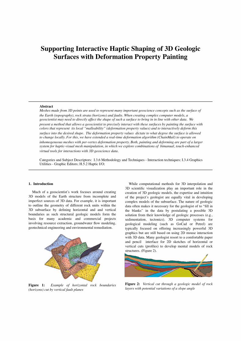
Figure 1: Example of horizontal rock boundaries (horizons) cut by vertical fault planes
While computational methods for 3D interpolation and 3D scientific visualization play an important role in the creation of 3D geologic models, the expertise and intuition of the project’s geologist are equally vital in developing complex models of the subsurface. The nature of geologic data often makes it necessary for the geologist of to “fill in the blanks” in the data by postulating a possible 3D solution from their knowledge of geologic processes (e.g., sedimentation, tectonics). 3D computer systems for geological modeling (such as GoCad or Petrel) are typically focused on offering increasingly powerful 3D graphics but are still based on using 2D mouse interaction with 3D data. Many geologist resort to a comfortable paper and pencil interface for 2D sketches of horizontal or vertical cuts (profiles) to develop mental models of rock structures. (Figure 2).
Figure 2: Vertical cut through a geologic model of rock layers with potential variations of a slope angle

However, while it is easy to correct the angle of a vertical separation (fault) with this, the 3D equivalent is considerably more difficult, in part because the of the lack of an integrated and easy to use 3D user interface. For example, a geologist may want to adjust the green fault shown in Figure 1 by bending its upper part like a sheet of metal but without affecting the part below the blue horizon.
Our work aims to create such an intuitive “3D canvas” for 3D models that not only overcomes the artificial nature of using 2D mouse interactions to express a intrinsically 3D interaction, but also uses force feedback as a stabilizing factor for freehand cutting, painting and deformations in real time.
In this paper we focus on a part of this larger process that which enables a geoscientist to precisely and directly deform these surfaces. The first step uses a paint metaphor to define inhomogeneous deformation property values (“malleability”) on the surface, effectively creating harder, softer and even frozen regions. In particular we deal with an algorithm for efficiently calculating the shape of a mesh during deformation if the mesh’s deformation property values are not homogeneous, or uniform, throughout the mesh but varies locally as an effect of the user’s painting process. We extended the underlying deformation algorithm to seamlessly incorporate these localized deformation property settings into a cloth-like, interactive deformation process. Note that we do not attempt to accurately simulate specific realistic material properties, such as a specific type of tissues, we employ deformation as a 3D interaction technique to enable the user to more efficiently and naturally translate a mental model of geology into a 3D computer model.
As this paint/deform combination can also be performed simultaneously, i.e., to soften or harden the model while it is being deformed, we also explore the potential for bimanual (two-handed) manipulation of 3D models.
2. Related Work
Previous research has investigated the use of haptic devices for painting and deforming surfaces, bimanual interaction, and interactive deformation. We previously presented higher-level aspects of our system for the manipulation of meshes with 3D graphics, haptics and sound [Authors2008a], [Authors2008b], including the painting and interactive cutting of meshes and an earlier version of the deformation algorithm. The work presented here focuses on the integration of a paint metaphor into the deformation algorithm and provides significantly more detail on its implementations and performance.
2.1. Haptics interaction with 3D models
SensAble’s family of PHANToM force feedback devices [MS94], shown in Figure 3, offer one method of enhancing 3D interactions with a form of touch. These grounded haptic devices provide active, kinesthetic feedback at the tip of a stylus. Although the overall haptic experience conveyed by the Phantom reduces the haptic experience to
a single point, it is well suited as an augmentation of a 3D graphics environment with touch-based interactions.
Figure 3: Phantom haptic force feedback device.
Previous research has explored the ability to paint and deform a 3D model with a PHANToM haptics device in related contexts. The inTouch system allowed users to paint colors on a 3D model and perform a simple fixed-heuristic deformation [GEL00]. Foskey et al. extended that system into an art tool for painting textures onto the 3D model [FOL02].
McDonnell et al. explore a volumetric framework using a control lattice; one interaction of that framework is “stiffness painting,” which allows the user to paint a stiffness value onto the nodes of a coarser control lattice with a haptics device [MQW01]. Cani et al. also present several approaches to manipulating virtual clay, and suggest that some approaches would benefit from using more than a single device [CA06]. These systems either operate on a control structure rather than directly on the data points, or operate on homogenous models.
2.2. Bimanual Interaction
Theoretical models for bimanual user interaction make a distinction between symmetric and asymmetric interaction [Gui87]. The bimanual interactions presented in this paper are all asymmetric interactions, where a dominant hand and a nondominant hand perform separate functions. Other authors have explored approaches for bimanual interactions with 3D shapes, both in 2D interactions [OKF*05], and in 3D interactions [GBK*01, HPP*98]. However, manipulations using multiple force-feedback devices, bimanual manipulations for geoscience-specific tasks remains largely unexplored.
2.3. ChainMail deformation
Gibson developed the original ChainMail algorithm to enable fast deformation of 2D and 3D objects containing hundreds of thousands of nodes [Gib97]. The deformation approximates rigid, deformable, elastic, and plastic materials with three deformation parameters: stretch, compression and shear. It provides a fast, real-time deformation method in which a limited number of points is moved by a certain distance depending on the displacement of an initial vertex.
2

Since its introduction, follow-up work on ChainMail diverged. In the Enhanced ChainMail algorithm, Schill et al. adapted the algorithm to operate on inhomogeneous meshes, meshes where the deformation property values could be different for each node on the mesh, however, Enhanced ChainMail was developed for quadrilateral meshes [SGB*98]. Li and Brodlie later developed the Generalized ChainMail algorithm to operate on arbitrary meshes in 3D [LB03]. This extension provides a framework for ChainMail deformation of tetrahedral and triangular meshes, however, Generalized ChainMail did not include the ability to deform inhomogeneous meshes.
In this paper, we present a technique that extends the Generalized ChainMail algorithm towards functionality described in the Enhanced ChainMail algorithm. This technique allows the deformation of tetrahedral meshes with inhomogeneous (non-uniform) deformation properties and includes a way to directly change these deformation property settings locally by painting them onto the mesh prior or during the deformation. We also present an example of how this type of direct interaction can be used in a geoscience setting.
3. Deformation property painting and deforming of 3D meshes
Our method for precisely manipulating a surface mesh consists of two actions that are typically performed in sequence but may also be performed simultaneously. The geoscientist first assigns local deformation property values values to specific parts of the mesh by painting them with the desired malleability values with a virtual paint brush tool.
For this step stylus of the haptic device turns into a virtual 3D brush, which the user can move along the surface of the object to feel the geometry of the surface and to steady the hand. This type of painting tool allows the geoscientist to assign inhomogeneous deformation properties values across the mesh. The inhomogeneous properties can set certain parts to deform more or less easily (react as soft or hard) or to protect them from deformation (react frozen). In the second action, the geoscientist switches from the paint tool to a deformation tool, grasps the mesh at a certain vertex and gradually displaces it by pulling or pushing this grasped vertex in any direction, The vertex’s displacement is continuously propagated to nearby vertices, leading to changes in displacement throughout the mesh. Internally, the deformation is defined with three parameters, a stretch value, a compression value and shear value, which are stored inside each of the mesh’s vertices.
During the deformation process, the geoscientists observes the visual effect of the deformation as the deformation propagates from that part to affect the object. They also feel a haptic effect equal to the magnitude of the deformation and can bump into other objects in the scene. These types of visual and haptic feedback during deformation guide the geoscientist towards their goal of deforming a part of a surface to align it with other 3D objects.
From the time the user initiates the deformation until they release it, the system performs a continuous simulation at interactive rates. During each frame, the result of displacing the point of contact from its initial position to its current position (given by the PHANToMs tip in 3D space). This is vital for intuitive modeling because it allows the user to seamlessly revert changes to the shape of the mesh if they deform too far. If the user moves the stylus too far while performing the deformation, they may simply move the point of contact closer to its initial position, and revert to the less severe deformation.
3.1. Visualizing the deformation property values
The power of deformation property painting comes from the fact that it allows the geoscientists to plan the deformation in a way that supports the transfer of their geoscience knowledge into the 3D computer model. Painting is a common metaphor for changing the visual appearance of 3D objects. Deformation property painting affects the object’s underlying deformation properties instead of color values, and those properties then govern the deformation behavior of specific areas of the mesh. For example, it might be desirable to set parts of a model to deform like a soft, rubber surface, other parts to deform like metal sheets and other parts to remain rigid. However, the act of material painting requires an immediate visual feedback as well. The geoscientist needs to know ahead of time what the deformation property values are at each point on the object to be able to “design” the distribution of the deformation accordingly.
One obvious solution maps the three deformation parameters, stretch, compression and shear value to the three RGB primary colors: red, blue and green, to visibly convey information about the mesh to the user. However, the choice of which color to map to which deformation parameter is arbitrary. Even worse, the properties often lie on different numeric ranges. Compression generally lies on the range between [0.0, 1.0], while stretch might be useful to define between [1.0, 2.0] or [1.0, 200.0] depending on the context of the deformation. This makes the use of a RGB color mapping problematic.
An alternative to the color mapping is to use a single value to represent the concept of malleability, ranging from 0.0 to 1.0, and to use a transfer function to convert this single malleability value to the three deformation property values. The advantage of using this grayscale malleability value is that can be mapped to a color scale that conveys the meaning of deformation more effectively that a translated RGB scheme. We have explored the use of a heat map color scale that mimics the color of iron at increasing temperatures. Our heat map ranges from a dark black, corresponding to a rigid cold iron, through warmer reds and oranges, to the white hot iron being the most malleable. This provides a clearer connection between color and the expected deformation behavior at different areas of the object–a white-colored hot area will react in a softer manner than a red-colored moderately-hot area, and a black-colored cold area will preserve its shape.
3

0 1Malleability
1
2
Pro
per
ty V
alu
eExample Malleability to Deformation Value Function
Stretch Compression Shear
Figure 4: Example linear transfer functions from malleability to deformation property values.
The transfer function underlying the heat map allows the user to control how the malleability value range maps onto the deformation property values. Figure 4 shows a simple configuration of transfer functions that map the malleability value to the three deformation property values (the red, green, and blue lines). While the example shown is a set of linear transfer functions this scheme creates a believable progression from hard to soft malleability, the use of nonlinear or spline transfer functions could help to fine tune the mapping to suit the application or to deliberately introduce jumps or steps.
3.2. Bimanual interaction
In addition to sequentially switching between using the paint and using the deform tools, the user may employ a second haptic device to either grasp the object or paint and deform the object simultaneously. Using a tool to grasp the object with the second device, the user may reposition and reorient the model with six degrees of freedom. This asymmetrical bimanual interaction allows the second hand to provide a frame of reference for the task of the primary hand. The user can use their second hand to reposition or reorient the object to make the painting or deformation task easier to perform.
The user may also use the paint and deform tools simultaneously. This allows the user to change the properties of the deformation while performing the deformation and immediately view the effect of the modified deformation property values. For example, if a user notices that the deformation creates and undesirable shape in certain parts of the model, they could apply a different malleability value on this part and the deformation changes accordingly. The user could also use the paint tool to reduce the malleability, of a region, or harden it, to preserve its location relative to its neighbors after starting a deformation.
3.3. Example of using deformation painting in a geoscience context
The following will illustrate an example of using the deformation property painting and subsequent deformation in the context of adjusting a horizontal rock boundary (horizon) to better model a vertical “step” (fault). To aid clarity we deliberately use a simplistic 3D geological
subsurface model and ignore many of the complicating factors encountered in real-world cases.
We assume that the geologist has generated an approximation of a horizontal boundary between two types of sedimentary rock (horizon) from one data set and, extrapolating from the Earth’s surface downwards, has created a mental model of where the step should be located. Looking at the horizon in Figure 5A, she determines that the position and shape of the step needs to be moved to be correct. Using the mesh as a 3D canvas, she prepares its deformation by painting three different deformation colors on it. To ensure that the vertical part (corresponding to the fault plane) remains internally unchanged, it is painted black. The connection with the horizontal part is painted white, to allow a very abrupt changes and the rest of the horizon is painted red to only permit small changes and to thus maintain it’s general structure (Figure 5 B).
Figure 5 (A-D): Applying deformation parameters to a subsurface mesh, and interactive deformation
A B
C
D
The geologist is now able to shape the vertical part of the 3D model. Using the Phantom’s stylus she touches the mesh with the deform tool (tweezers), holds down the stylus’s button and moves the tip laterally, thus creating an offset from the initial position. The deformation algorithm translates the offset into a mesh deformation that honors the underlying deformation properties indicated by the colors painted on the mesh earlier (Figure 5C). Because this deformation is updated in real time, the geologist can adjust it until it conforms to the desired shape (Figure 5D).
4

4. ChainMail algorithm for inhomogeneous mesh deformation
The problem with using the Generalized ChainMail algorithm when deforming an object with inhomogeneous deformation properties is that it can allow malleable points to determine the final position of any stiffer points. Instead of preserving a constant relative position to neighboring points in the rigid areas, it causes that relative position to change. This results in ripples through the region that is supposed to remain rigid, as the deformation propagates from malleable points to stiff points. The Generalized ChainMail algorithm does not differentiate between points based on malleability, but instead propagates using a tree traversal or outward spiral. Before detailing the necessary modifications to the Generalized ChainMail algorithm, it is useful to explain more about how the algorithm works.
Displacement
Figure 6: A ChainMail displacement that propagates from the malleable grey nodes to the rigid black nodes fails to preserve the fixed displacement between the black nodes.
Shear
Stretch
Compression
Sponsor
Displacement
Figure 7: Valid region of a point before and after a ChainMail deformation displaces its sponsor
4.1. Details of Generalized ChainMail
The ChainMail algorithm was designed for fast simulation of deformable objects; it it focuses on achieving interactive rates to provide the user with immediate feedback about the shape of the deformation. To keep the complexity of the algorithm low, each node is only moved once and not every node needs to be analyzed. Even though a given node often has several neighboring nodes that might affect its movement, only one neighbor sponsors the movement of that node. A node will sponsor the movement of its neighbors only if it is displaced by the deformation. This means that the algorithm only iterates through the region of nodes affected by the deformation. The deformation spreads outward from the point of contact. Each node displaced by the deformation sponsors the analysis of the nodes connected to it, the neighboring nodes. The propagation of the deformation terminates when a given node already lies within the valid region.
The valid region is a bounding box around each candidate node for deformation that is influenced by both the sponsoring node and the deformation parameter values. The origin of the bounding box is the original displacement of the candidate measured from its sponsor. If the sponsor is displaced by the deformation, the origin of the valid region is displaced by the same amount. The dimensions of the bounding box are defined by the deformation parameter values. The stretch parameter elongates the box along each component axis of the displacement. The compression parameter determines how closely the bounding box may approach sponsoring node. The shear parameter adds a proportion of the perpendicular components of the original displacement to each dimension of the bounding box. Shear allows a node with a displacement only in the z-axis to move on the x or y axis to absorb the deformation. Note that the origin of the valid region is only at the center of the valid region if the stretch and compression values are the same distance from 1.0 in opposite directions on the line.
VRorigin = VRcenter iff. stretch = 1.0 - compression
Since each displaced node sponsors a number of neighboring nodes, it is necessary to store the candidates awaiting analysis in a data structure. Li and Brodlie suggest the use of a tree or a FIFO queue for Generalized ChainMail [LB03]. The choice of structure influences the propagation of the deformation, with the tree structure producing vein-like propagations, and the queue producing a smoother spiral propagation.
4.2. Malleability gradient propagation
The ChainMail algorithm must preserve the relative displacement between sponsor and neighbor nodes in the rigid portions of the mesh. Enhanced ChainMail satisfies this requirement by calculating the constraint violation of each neighboring node at the time when the algorithm displaces a node [SGB98]. The constraint violation is the distance between a neighbor and the closest point in its valid region. The Enhanced ChainMail algorithm then displaces the neighbor with the largest constraint violation and moves on to process its neighbors.
An alternate method to prevent malleable nodes from sponsoring stiffer nodes is to require that a deformation propagate down a malleability gradient, through stiff nodes before spreading to more malleable nodes. This method also preserves the relative displacement between neighboring rigid nodes by ensuring that a node may only sponsor the displacement of an equal or more malleable node.
The exception to this rule is that a malleable node can sponsor a stiffer node for deformation if there is no stiffer candidate awaiting deformation in the queue. This exception prevents a deformation that originates in a softer region from stretching infinitely along the border of a stiffer region; the first stiff node encountered will propagate the deformation through the rest of the stiff region.
5

4.3. Priority queue for deformation candidates
One straightforward approach to enforcing malleability gradient propagation is to use a priority queue instead of a FIFO queue or a tree for the candidates that have been sponsored for deformation but not yet analyzed. The priority queue would prioritize candidates with lower malleability values over candidates with higher malleability values. This would prioritize the nodes most affected by a deformation without calculating their valid region since the size of the valid region decreases as the malleability of a node decreases.
While the priority queue ensures that candidates with lower malleability are displaced first by the deformation, it does not carry any guarantee that it preserves FIFO (first in - first out) ordering among nodes with equal priority. Many priority queue implementations are based on underlying heap operations, such as the c++ Standard Template Library (STL) priority queue implementation [ISO14882]. This heap structure can lead to a vein-like propagation through areas of equal malleability, as demonstrated in Figure 8 and the two provided video files. This propagation results in ridge-like shapes through malleable regions and thus in deformations that are inconsistent when the user makes small movements between frames of the interactive deformation.
Figure 8: Comparison of candidate data structures for ChainMail deformation (clockwise from top left): before deformation, FIFO queue, FIFO-preserving priority queue, simple priority queue.
Before deformation FIFO queue
FIFO priority queuePriority queue
A priority queue that preserves FIFO ordering among candidates with equal malleability values produces a much more consistent deformation, as shown in Figure 8. This type of queue provides a spiral-like propagation through areas of equal malleability, leading to deformation results that are less severe in appearance and slope. They also have the advantage of being much more predictable, which is important for providing precise control to a geoscientist.
The use of a priority queue instead of a simple FIFO queue to store the candidates does impose an increase in complexity. The priority queue we used in our implementation is logarithmic in complexity for insert and removal operations, while a simple queue would be constant in complexity for those same operations. However this is proportional to the number of candidates awaiting analysis, and bounded by the size of the deformation, just as the original ChainMail algorithm. The Generalized ChainMail algorithm also suggested the use of a tree structure to store the candidates, which would also carry a similar increase in complexity over the simple queue [LB03]. In practice, the deformation remained interactive even with the additional complexity in the queue insert and removal operations, which we will detail further in the next section.
5. Results
We implemented this interaction as part of a larger haptic manipulation system using H3DAPI and other open source projects [H3D]. H3DAPI provides a efficient and flexible scenegraph API (in C++ and Python) to implement sophisticated haptic interactions with 3D objects.
The result of using the FIFO-preserving priority queue on a number of different deformations is presented in Table 1. We compared it to implementations of a normal priority queue and a simple FIFO queue to store the candidates awaiting deformation. We measured the deformation by the number of nodes that it displaced, not the vertex count of the model. The results are reported in millisecond timings collected as the system performed the deformation. During the deformation, there were also two high-priority haptic threads running that calculate the force-feedback for two hands. We performed these tests on an an ordinary graphics PC: dual-core 2.6 GHz AMD 5000+ with 2GB of RAM and a Nvidia 8600GT video card with 256 MB of VRAM.
nodes displaced 9,152 14,088 17,289 18,225 29,241FIFO queue (ms) 38 76 111 159 195priority queue (ms) 46 96 130 164 302FIFO priority queue (ms) 45 79 125 167 298Table 1: Comparison of timings in (ms) for deformation candidate structures
The timings suggest that it is possible to improve the quality of mesh deformation with inhomogeneous properties while maintaining interactive rates. Although the FIFO-preserving priority queue has more expensive insert and removal operations, the measured performance hit is not severe. Even for relatively large numbers of vertices.(around 29,000 nodes) the increase is only around 50% (from 200 ms to 300 ms).
6. Conclusions and future work
We presented a method for giving a geoscientist precise control over the deformation property values of an inhomogeneous mesh. The painting interaction allows precise control over the malleability values of the mesh to
6

affect locally varying degrees of deformation. We also presented enhancement of the Generalized ChainMail algorithm that allows it to perform a deformation of an inhomogeneous mesh. The implementation allows for interactive exploration of bimanual painting and deformation. A pilot study is underway to determine the effectiveness of this bimanual interaction.
7. Acknowledgements
8. References
[Authors08a] to be replaced
[Authors08b] to be replaced
[CA06] CANI M.-P., ANGELIDIS A.: Towards virtual clay. In Proc. SIGGRAPH '06 Courses (2006), pp. 67–83.
[FOL02] FOSKEY M., OTADUY M., LIN M.: ArtNova: touch-enabled 3D model design. In Proc. IEEE Virtual Reality (2002), pp. 119–126.
[GBK*01] GROSSMAN T., BALAKRISHNAN R., KURTENBACH G., FITZMAURICE G., KHAN A., BUXTON B.: Interaction techniques for 3D modeling on large displays. In Proc. Interactive 3D graphics (2001), pp. 17-23.
[GEL00] GREGORY A., EHMANN S., LIN M.: inTouch: interactive multiresolution modeling and 3D painting with a haptic interface. In Proc. IEEE Virtual Reality (2000), pp. 45–52.
[Gib97] GIBSON S.F.F.: 3D chainmail: a fast algorithm for deforming volumetric objects. In Proc. Interactive 3D Graphics (1997), pp. 149–154.
[Gui87] Guiard Y.: Asymmetric division of labor in human skilled bimanual action: The kinematic chain as a model. Journal of Motor Behavior 19, 4 (1987), pp. 486–517.
[H3D] H3DAPI. http://www.h3dapi.org
[HPP*98] HINCKLEY K., PAUSH R., PROFFITT D., KASSELL N.: Two-handed virtual manipulation. ACM Transactions on Computer-Human Interaction (1998), pp. 260-302.
[LB03] LI Y., BRODLIE, K.: Soft Object Modelling with Generalised ChainMail-Extending the Boundaries of Web-based Graphics. Computer Graphics Forum 22, 4 (2003), pp. 717–727.
[ISO14882] ISO/IEC 14882 Programming languages: C++. American National Standards Institute, (1998), pp. 480-481.
[MS94] MASSIE T., SALISBURY J.: The PHANTOM Haptic Interface: A Device for Probing Virtual Objects. In Proc. ASME Winter Annual Meeting, Symposium on Haptic Interfaces for Virtual Environment and Teleoperator Systems DSC 55-1 (1994).
[MQW01] MCDONNELL K., QIN H., WLODARCZYK R.: Virtual clay: a real-time sculpting system with haptic toolkits. In Proc. I3D '01 (2001), pp. 179–190.
[OKF*05] OWEN R., KURTENBACH G, FITZMAURICE G., BAUDEL T., BUXTON B.: When it gets more difficult, use both hands: exploring bimanual curve manipulation. In Proc. Graphics Interface 2005 (2005), pp. 17–24.
[SGB*98] SCHILL M.A., GIBSON S.F.F., BENDER H.-J., MÄNNER, R.: Biomechanical simulation of the vitreous humor in the eye using an Enhanced ChainMail Algorithm. LNCS 1496, (1998), pp. 679–687.
7