supportive robotic welding system for heavy, small series
TRANSCRIPT
Acta Polytechnica Hungarica Vol. 15, No. 8, 2018
– 141 –
Supportive Robotic Welding System for Heavy,
Small Series Production with Non-Uniform
Welding Grooves
Csongor Márk Horváth, Péter Korondi
Department of Mechatronics, Optics and Mechanical Engineering Informatics,
Faculty of Mechanical Engineering, Budapest University of Technology and Eco-
nomics, Műegyetem rakpart 1, 1111 Budapest, Hungary
[email protected], [email protected]
Abstract: Heavy welding is a demanding task with high robotization potential. This applies
especially for the runners of Francis hydropower turbines, due to the high working costs
and EHS requirements in Europe. However, heavy welding is often related to small-series
production with long processing time. This sets high demands on the planning and monitor-
ing functionality of the robot system. The research in this field is gaining momentum, yet
very few articles suggest suitable solutions. This paper presents a robotic welding control
system design and application that facilitates the planning, control, and monitoring of the
welding process of non-uniform grooves of large-dimension joints. Its primary and unique
characteristic is the simplified operator assisted programming method, where the three-
dimensional path modification problem is translated into consecutive two-dimensional
modifications. Therefore, reference cross-sections are created along the welding groove,
where the sequence planning task of multi-pass weld bead placement is performed, and to
the online modifications together with the adjustments are referred. The planning, changes
and process supervision are supported by the robot system to handle uncertainties along
the welding groove and adaptively utilize the robot operator experience. The activities are
tracked and organized to supply information for later performance enhancement and reus-
ability between similar processes. The supportive system design is particularly suitable for
advanced, large-dimension, heavy robotic welding applications. A use case is presented on
a welding a runner of Francis hydropower turbine.
Keywords: robotic welding; multi-pass welding; non-uniform groove; small series produc-
tion
Cs .M. Horváth et al. Supportive Robotic Welding System for Heavy, Small Series Production with Non-Uniform Welding Grooves
– 142 –
1 Introduction
1.1 Welding Robots for Small and Medium Sized Companies
The industry is facing major challenges increasing efficiency and productivity to
stay competitive. The small and medium sized enterprises (SMEs) are an essential
part of the countries’ economy, as they represent 99 per cent of all enterprises.
The domain of industrial robot usage and integration has been dominated by the
large-scale automotive and electronics industries [19, 30]. With 27%, the automo-
tive sector is the largest in the welding industry. From all application fields, the
most common is welding and soldering (30%), which typically implemented for
large volume production that requires high product mix and short production cy-
cle. Although recent trends show an expansion of robot adoption outside of these
areas, the progression into new fields is moderate.
Even though the SMEs are showing increasing demand for robotization, their
demands differ from the traditional robot applications because their business mod-
els are more likely to involve wide range and small series production [26]. The
tasks are often not well defined, heavy, fatiguing and hazardous, with substantial
environmental load and stress level for the workers [35]. The limited proof of
performance of the technologies are the technical barriers that limit the adoption
of robotic systems by SMEs even in the most desired application areas.
Despite the quality and efficiency that a today’s robotic welding systems can pro-
vide for the general welding industry, skilled human welders cannot yet be re-
placed in welding of joints in complex structures due to various reasons: high
initial costs, tedious teaching procedure and long commissioning time. Thus, most
of the welding is done manually or semi-automatically in fields such as the off-
shore industry, ship manufacturing or hydropower turbine production [17].
1.2 Challenges in Heavy Multi-Pass Welding
Several challenges arise when the application comes to robotic heavy welding
despite the convenience of using robotic welding systems. Typical challenges
related to the small series production are the following:
1. Cost and personnel: SMEs have limited resources; The high initial costs of
installations with the lack of dedicated and specialized personnel restrict the
possibilities to deploy robotized solutions as well as the use of complex of-
fline programming systems at SMEs facilities.
2. Task complexity: Large-dimension welding joints typically have thick and
non-uniform welding grooves. Therefore, significant amount of time and so-

Acta Polytechnica Hungarica Vol. 15, No. 8, 2018
– 143 –
phisticated approach are necessary to handle the multi-pass welding process.
Such grooves are often still welded manually due to their complex shape.
3. Environment: The heavy, fatiguing and hazardous manual welding, with
substantial environmental load and stress level for the workers effects directly
the production and need to be conformed with the Environmental and health
(EHS) regulations
4. Programming time: Small series production requires significant effort spent
on the programming of the welding robot for the new part. The currently
available robotic solutions are lacking a detailed model based multi-pass
welding planning. An accurate multi-pass welding plan can shorten the prepa-
ration and welding time.
5. Handle uncertainties: Robots cannot make corrective decisions autonomously.
Thus, decision making support is required, either by the sensors and the con-
trol system or through intuitive user interaction. Detailed and accurate
knowledge about the process increase the applicability range of the planning,
but, additional online handling of the arising uncertainties is inevitable.
The welding groove complexity of large-dimension joints originates mainly from
the geometry and the varied thickness of the base materials. Regardless of the
careful edge preparation and the standard conformity, weld joints have thick non-
uniform grooves. Such examples are the tubular joints in pipeline manufacturing
or the grooves on the hydropower turbine runners at the blades.
This paper presents a robotic welding control system design and application that
facilitates the planning, control, and monitoring of the welding process of non-
uniform grooves. Its primary and unique characteristic is the simplified operator
assisted programming method. It contains an offline programming module with
dedicated consideration of the non-uniformities of the welding groove and the
simplified online programming module, supporting the welding path adjustment
and process supervision to handle uncertainties. The supportive system design is
presented on a use case with a runner of Francis hydropower turbine.
2 Background
2.1 Welding Robot Systems
Welding robots represent the largest fraction of applications deploying industrial
manipulators. The most common techniques apply Metal Inert/Active Gas weld-
ing (MIG/MAG), the Tungsten Inert Gas (TIG), and Laser Beam Welding. Cur-
rently, automated robotic welding is gaining momentum due to the high wage

Cs .M. Horváth et al. Supportive Robotic Welding System for Heavy, Small Series Production with Non-Uniform Welding Grooves
– 144 –
levels and the dropping installation and operation cost of a robot system. This
offers new opportunities to automate small series production, although these are
the result of several stages of development in the welding robot systems.
In the earliest, first generation robotic welding applications, the welding was per-
formed in two runs; the first run was dedicated to learning the seam geometry and
the second run was the actual tracking and welding. The second generation of
robotic welding systems’ development reduced the number of necessary runs by
performing seam learning and tracking simultaneously, in real-time. The latest,
third-generation welding robot systems are not only operated in real-time but
within unstructured environments and learning the rapidly changing geometry of
the seam during operation [36].
According to Pires [36], an automated robotic welding system design can be im-
plemented in three different phases with the final goal to achieve decent perfor-
mance and a high-quality weld. The first phase is the preparation, where the weld-
ing scene is set up and the offline programming is executed. The second phase is
the welding phase, when the welding process is performed based on the continu-
ous decisions made by the operator or the robot system to achieve the required
weld quality. The last phase is the analysis phase, in which the welds are exam-
ined, and a decision made about the acceptance. The considered changes are col-
lected and evaluated.
2.2 Hardware Components
Modern welding robot systems contain an integration of the robot manipulator,
robot controller, welding equipment, work-piece positioner, supportive sensor
system, and welding safety devices [12,31]. Those multiple units require
coordinated or synchronized motion to access the entire work-piece, minimize idle
time and maximize the arc/welding time. It often connected to a sensor system
supporting the welding process and a computer for process control and data
collection. In advanced operations, the standard computer peripheries are extended
by additional Human-Machine Interfaces (HMI). A schematic of a general robot
system is shown in Figure 1. Similar equipment used for the realization of the
robotic welding system presented in this paper.
Sensors in robotic welding are used to detect and measure process features along
with geometrical parameters, or monitor and control welding process parameters
by technological sensors [13, 21, 48]. The first can be achieved in several ways
applying most often optical sensors to detect and measure the joint geometry
(seam finding, seam tracking) [49, 50], as well as the weld pool geometry and
location [9, 37]. Research on robot systems for small series production has been
conducted to determine the main factors for the users. Besides the flexibility, user-
friendliness, shorter programming time, and robustness of operation, the possibil-
ity to integrate sensors both for simulation and during runtime was listed as signif-

Acta Polytechnica Hungarica Vol. 15, No. 8, 2018
– 145 –
icant. In this context, sensors used for seam tracking or to control the welding
process are considered equally important [3]. Weld quality monitoring in robotic
welding provides automatic detection of weld defects by analysing the process
parameters and by comparing these with the nominal values [38]. It also could
include non-destructive inspection methods such as radiography, ultrasonic, vi-
sion, magnetic detection, eddy current, acoustic measurements [55] or electro-
magnetic sensor [1].
Figure 1
General robotic welding system
Due to the challenging formation of the high temperature welding environment
(high current, spatter, liquid metal, high temperature), it is difficult to apply sen-
sors to measure the welding parameters directly. These problems cause that the
parameters that can be observed are not concurring with the parameters needed to
be controlled. Furthermore, it is not trivial to carry out a simple feedback control.
The complexity can be solved by developing models to map the observable pa-
rameters to appropriate actions on issues within the relevancy of the welding spec-
ification procedure. In this, the productivity and quality measures are defined
together with the nominal welding process control parameters and geometry in-
formation to produce the desired weld. A model based control should, therefore,
unify the data from the sensors, the welding procedure specifications and the ro-
botic welding system specific restrictions [36].

Cs .M. Horváth et al. Supportive Robotic Welding System for Heavy, Small Series Production with Non-Uniform Welding Grooves
– 146 –
2.3 Programming Methods
Two main categories of programming methods exist in practical industrial appli-
cations: online programming, including the lead-through and walk-through, and
offline programming (OLP). Conventional online programming allows for precise
control of the straightforward process with simple path definitions and work-piece
geometry. Due to the low initial cost and low programming skills required, it is
widely used. However, the entire production line is disrupted during teaching due
to the downtime of the robot. Moreover, the taught program has limited flexibility
and is unable to adapt to the current welding scenario and problems encountered
in the welding operation without additional control [34].
More advanced programming methods are the operator-assisted online program-
ming, such as the lead- and walk-through methods or the sensor guided program-
ming. By walk-through programming, the robot arm itself is configured to be able
to be moved by the operator, to teach the robot path based on the built-in [2, 7, 42]
or external sensors [41]. Furthermore, experiments and research have been con-
ducted to develop admittance controller driven teaching methods, deploying ex-
ternal tools [27, 44] and vision systems [33, 43, 45]. Besides the progress achieved
on the online programming to make it more intuitive and fitting of the operator
skills, most of the research outcomes are still not commercially available [34].
Using OLP methods, data based on CAD/CAM is a common practice in many
areas of the industry, especially automation systems with large product volumes.
Figure 2 illustrates the workflow of OLP. Many software and simulation tools are
available to provide direct robot trajectories from CAD data of the work-pieces,
robots, and fixtures used in the cell [20]. Some of the most advanced techniques
apply the recent results of research in the field of Cyber-Physical Systems [10, 29,
39] and the Digital Twin [32, 46] related developments. The main advantages are
that the generated code is reusable, flexible for modifications, and complex paths
can be produced with reduced production downtime [18]. However, the OLP
systems utilization in SMEs is limited due to the economic disadvantages for
small volume production caused by the high cost of the OLP packages and the
programming overhead for customization [34].
Figure 2
Key steps of offline programming. Reprinted from [34]
Acta Polytechnica Hungarica Vol. 15, No. 8, 2018
– 147 –
In welding, most of the available OLP software is considering the welding seam
as a well-defined, uniform groove. The existing planning methods of multi-pass
welding [25, 52, 53] based on a generally constant grove cross-sectional area
where the differences in the geometry are results of errors. Only a few studies [6,
51] analysed how to handle the non-uniformity of the welding groove geometry
systematically. These address the groove representation with straight edges, where
the measured profile showed different shape, without consideration of the curva-
ture of the edge preparation. The layer height calculation was based on trigono-
metrical principles. The introduced welding groove segmentation based on the
weld bead placement strategy and the welding position difference. The groove
geometry changes affected the weld bead numbers in the layers and the number of
the layer number. One of the main conclusions was that the weld bead number in
the layers should be constant, but the layer number would vary from segment to
segment concerning the welding quality.
2.5 Human Behaviour Models and Human-Machine Interfaces
The mainstream trend in modern welding industry is mechanization and automa-
tion. However, human welders may be preferred over mechanized welding con-
trol systems in applications where experience-based behaviour in response to the
received information is required [54]. Studies have been conducted to develop
models of the mechanism of welders’ experience-based behaviour to create a
controller in automated welding. It has been found, that the welder makes deci-
sions primarily based on past learned experiences and the humanistic approach of
the acquired sensory information is imprecise. It only reflects partial truth about
the instant status of the welding process [5, 23].
Another approach is to create HMI to overcome the barriers between the process
and the operator, by improving the maintenance and support activities through
remote communication [4]. This can be exploited by cyber-physical devices [8],
cognitive info-communication methods [16, 22], or multi-modal man-machine
communication (4MC) [28, 47]. Those latter methods utilize multiple senses of
the human and create sensor bridging to transfer the otherwise naturally acquired
data (NAD) [22]. Information from one sensor must be translated into another and
transferred through non-conventional communication channels (Figure 3). There-
fore, the goal of multi-modal human-machine communication is to realize natural,
intuitive and efficient information flow between the remote operator and the local
system [47] as well as create a virtual environment that makes the remote operator
feeling next to the system [11, 14, 15, 24].
Based on the overviewed literature, the guidelines can be identified for the devel-
opment of a heavy multi-pass welding robot system for SMEs. Cost and time
efficient programming method is required to provide alternatives to the expensive
and general OLP methods along with the slow but flexible online programming.

Cs .M. Horváth et al. Supportive Robotic Welding System for Heavy, Small Series Production with Non-Uniform Welding Grooves
– 148 –
The development of a simplified OLP system is defined to achieve the necessary
complexity level by automating the auxiliary, non-welding tasks; simplify online
programming by developing HMI for the execution of the essential modifications
integrated it into the control system. The sensor system must be integrated to sup-
port the operator’s modification activity.
Figure 3
Differences between conventional and non-conventional information channels [16]
The simplified and process-oriented environment could balance out the missing
skill set of the robot operator, and the supportive sensory system provides the
necessary information to utilize the operator experience in welding.
3 Control System Structure for Heavy, Multi-Pass
Robotic welding
This section provides a general description of the system design principles for
welding tasks with large-dimension joints and non-uniform grooves. The system
design is intended to replace the manual welding procedure directly, but it also
needs to be able to compete with the online and offline programming methods.
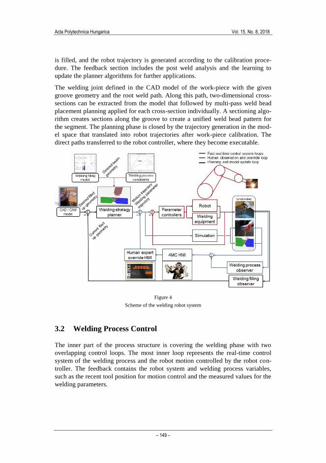
Figure 4 provides the schematic for such a system that can be considered as a
cascade control system design. This contains three different control loops with
different speed and functions, furthermore divided into the phases discussed in
Section 2.1. The process consists of the preparation, offline planning and pro-
gramming, the welding process control, and finally the observation and analysis.
3.1 Preparation and Offline Programming
The process starts with the welding scene setup, where the preparation includes
the work-piece positioning, the welding method and the additional physical com-
ponents definition (shielding gas, feed wire, preheating). The outermost loop of
the cascade control system is offline programming and analysis loop, which per-
formed between the different welding setups. Its forward section contains the
offline programming, where the CAD/CAM models are handled. Based on the
planning strategy of multi-pass welding and the weld bead models, the weld seam
Acta Polytechnica Hungarica Vol. 15, No. 8, 2018
– 149 –
is filled, and the robot trajectory is generated according to the calibration proce-
dure. The feedback section includes the post weld analysis and the learning to
update the planner algorithms for further applications.
The welding joint defined in the CAD model of the work-piece with the given
groove geometry and the root weld path. Along this path, two-dimensional cross-
sections can be extracted from the model that followed by multi-pass weld bead
placement planning applied for each cross-section individually. A sectioning algo-
rithm creates sections along the groove to create a unified weld bead pattern for
the segment. The planning phase is closed by the trajectory generation in the mod-
el space that translated into robot trajectories after work-piece calibration. The
direct paths transferred to the robot controller, where they become executable.
Figure 4
Scheme of the welding robot system
3.2 Welding Process Control
The inner part of the process structure is covering the welding phase with two
overlapping control loops. The most inner loop represents the real-time control
system of the welding process and the robot motion controlled by the robot con-
troller. The feedback contains the robot system and welding process variables,
such as the recent tool position for motion control and the measured values for the
welding parameters.
Cs .M. Horváth et al. Supportive Robotic Welding System for Heavy, Small Series Production with Non-Uniform Welding Grooves
– 150 –
The middle loop is the human interaction loop where the adaption is performed to
the immediate situation during the welding process or to the desired path during
the path setup and verification. Here, the feedback loop includes the observations
of the welding process and the correction actions from the operator. On the given
user interface, the cell operator could give commands to the system to perform the
predefined sub-tasks that includes the path verifications and the welding execut-
ing. Furthermore, it offers path adjustments both during the dry-run and the
weld-run.
3.3 Observation and Post-Weld Analysis
The post-weld analysis and observation are performed to validate the welding
process goodness and decide about the acceptance or detect the defects of the
welding. The proposed system is intended to handle all the available information
collected during the preparation and the welding process, including the synchro-
nized data gathered from the robot controller (speed, position and orientation
information, input and output values, internal variable values), from the welding
power source (variable welding parameters, pre-set welding parameters), and from
the cameras and sensors. The data collection extended with the weld qualification
measurements (visual inspection, destructive and non-destructive examination
methods) can provide the information needed for a well-supported decision to
adjust the reference parameters for the future welding processes.
4 Offline Programming and Path Verification
The programming of the robot and the verification of the welding path are linked
together, and the proposed system supports this process with minimal user interac-
tion. Figure 5 shows how the same path is represented in the different scenarios:
first in the path definition phase, then in simulation, finally the path verification.
This section provides descriptions about the offline programming system, includ-
ing the transformation chain from the predefined machining path definition in
model space to executable robot trajectory.

Acta Polytechnica Hungarica Vol. 15, No. 8, 2018
– 151 –
Figure 5
Root welding path verification utilizing a digital twin
4.1 Root Weld Path Definition and Reference Cross-Sections
The root weld path is defined during the offline programming and preparation
phase and serves later as a reference trajectory of the multi-pass welding planning.
The offline programming tool reads the CAD file of the work-piece then the
groove definition is given including the reference cross-sections and the root weld
path. The root weld path is built up from task points and normal vectors where the
distribution and density of the points define the resolution of the path on the nec-
essary level (straight grooves requires fewer control points compared to curvy
grooves) and the normal vectors determining the initial welding torch orientation
as shown in Figure 6. The schematic representation of the coordinate system and
vector definitions are given in Figure 7. The reference coordinate system for the
CAD/CAM data is defined as r, the robot’s base coordinate system is defined as b.
Figure 6

Cs .M. Horváth et al. Supportive Robotic Welding System for Heavy, Small Series Production with Non-Uniform Welding Grooves
– 152 –
Root weld path trajectory definition in the model space as the digital representation of the work-piece
The task point coordinates 𝐶 are defined in the model r coordinates and given in
the path definition description with the path normal vector a, which is a physical
reference for the initial welding torch orientation. The tangent vector of the path n
is targeting the next task point respecting the predefined task direction. The third
vector at the task point s is the cross product of the a and n. The task path descrip-
tion in the reference r model space coordinated system is denoted as {𝑻𝑪}𝒓 that
includes each task points and their local coordinate system definition and provides
the basis for the robot trajectory planning.
Reference cross-sections are generated from the CAD model along the root weld
path to reduce the complexity of the path adjustments and to be used later during
the multi-pass welding planning phase. The cross-sections are perpendicular to the
path trajectory and defined for each task point on the plane of the local coordinate
system t, represented by the two vectors a and s, where vector a defines the 𝑧-axis
and vector s defines the 𝑦-axis. The process of the transformation steps and ma-
trixes is shown in Figure 8. and described in detail in the following.
Figure 7
Definition of the reference coordinate systems
Figure 8
Structure of coordinate transformation – from CAD to executable motion trajectory

Acta Polytechnica Hungarica Vol. 15, No. 8, 2018
– 153 –
4.2 Welding Process Planning
The central part of the process planning in offline programming is the definition of
the multi-pass weld bead pattern and the corresponding robot trajectory definition.
During the multi-pass welding planning, the main controllable online variable
settings collected for each weld bead that influences the welding process, namely
arc voltage, arc current, torch travel speed, and wire feed rate. The welding pa-
rameters range is defined in the Welding Procedure Specifications as constraints
for all weld bead related planning and modelling.
The commercially available welding systems do not contain model-based planning
capability considering the weld bead profile properties. Such modules often only
generate a symmetric and simplified weld bead layout, which usually requires
major adjustments during the operation. In this proposed method, the positions of
the weld beads are defined based on certain placement strategies and based on
consideration of the groove geometry and the model of the weld bead profile func-
tion. Further plan-specific parameters are also included, such as the length of the
seams, the welding torch orientation and collision avoidance modifications. The
block diagram of the planning process is presented in Figure 9.
The planning process starts with the groove modelling (Block A1), when the
groove’s mathematical description made for each characteristic cross-section from
the digital representation of the work-piece and the weld groove (CAD/CAM or
profile scan data as I1-I3). The next step is the generation of the initial weld bead
placement sequence in each given groove cross-sections handled by the Sequence
Planner (Block A2). The weld bead sizes, shapes and welding parameters are
defined by the Welding Filling Model (C1).
Figure 9
Planning process of multi-pass welding
The model uniqueness lays in the realistic representation of the weld bead profile
function in the layer-by-layer deposition, instead of the conventional quadrilateral
approximation, described by Yan, et al. [51]. The weld bead shapes are described
as symmetric curve functions, and the edge preparation of the grooves defined as
continuous convex functions. The produced ripple top surface of the layers is

Cs .M. Horváth et al. Supportive Robotic Welding System for Heavy, Small Series Production with Non-Uniform Welding Grooves
– 154 –
better suited to reality than the flat surface approximations, therefore, the cumulat-
ing error is significantly reduced during the deposition. The exact implementation
of the Welding Filling Model and the representation model of the weld bead pro-
file is not synergic part of this paper. When the pattern is generated, the Sequence
Interpolation section (Block A3) is activated to assure the pattern smoothness,
creating sections for a consistent plan and starting the new iteration process to
apply a generally accepted plan. This generates the initial robot trajectories with
connected welding parameter settings. The last step (Block A4) is to adjust the
recently created robot trajectories concerning the confined space access re-
striction, to avoid collisions.
4.3 Calibration and Path Definition
The trajectories generated by the multi-pass welding planner are referred to the
local coordinate system in the model space but need to be transferred to the robot
coordinate system before executions by coinciding with the location of the physi-
cal work-piece and the CAD model. This is done by performing a calibration
procedure, through determining the position of the same reference coordinate
system on the physical work-piece as being used in the virtual world where the
CAD / CAM model is defined. During the calibration procedure, the 𝑻𝒓𝒃 transfor-
mation matrix determines the translation and rotation from the model space r
coordinate system to the robot’s base coordinate system b. resulting the new coor-
dinate definition as {𝑻𝐶}𝑏 , according to Equation 1.
{𝑻𝑪}𝒃 = 𝑻𝒓𝒃 × {𝑻𝑪}𝒓 ( 1 )
5 Online Process Control
By the end of the offline programming and process planning, the input parameters
are available for the online process control that is the primary process in the weld-
ing phase [40]. The input parameters are the motion trajectory and the welding
parameter trajectory. In this section, the block of the online process control is
discussed (Figure 4). It includes the control of the physical robot system with the
connected devices, the digital twin which is running parallel to the welding pro-
cess, the welding process observer, which is acquiring the information about the
process, and the human-in-the-loop.
The process flow can be described as the following: The reference motion trajec-
tory and welding parameter trajectory are transferred to the parameter controllers.
Those reference values translate into executable parameter sets and sections com-
municated to the physical devices (robot controller and welding power source).
The physical signals feedback to the parameter controllers providing stable signals

Acta Polytechnica Hungarica Vol. 15, No. 8, 2018
– 155 –
to the welding process. The control loop implementation is distributed between
the physical devices including the factory designed parameter controls. This pa-
rameter control with the devices is the most inner loop of the cascade control
system. The digital twin is running parallel to this loop including the digital repre-
sentations of the devices and the work-piece.
The welding process observer is the feedback of the welding process, including
the supportive sensor system and overlapped with the information gained from the
digital twin. Practically, the latter provides information about the hardly observa-
ble parameters, such as the current cross-sections, the already and the future de-
posited weld beads’ reference torch position, as well as collision alerts. The feed-
back loop includes the human operator, for whom the information is translated
through 4MC devices and if necessary overwrites the process references.
5.1 Applying Path Modifications: Translation and Rotation
Our approach to applying path modifications in the welding process is to separate
the translation modifications from the rotations. Thus, the three-dimensional path
modification problem is translated into consecutive two-dimensional modifica-
tions, where the reference cross-sections are serving as a modification plane. The
reference cross-sections remain constant during the process regardless of the ap-
plied path modifications. The multi-pass welding planning becomes trackable for
the operator. The user translation modifications are given along the reference
cross-sections main axes as Δy and Δz, relative to t task point. The new point 𝒕’ is
the result of the translation ∆𝒑𝒕 defined by {𝑻𝑪′ }𝒃 as shown in Equations 2.
{𝑻𝑪′ }𝒃 = {𝑻𝑪}𝒃 × ∆𝒑𝒕 ( 2 )
The user rotations ∆𝑹𝒙, 𝝋and ∆𝑹𝒚, 𝜽 are applied to the translated point t’, the trans-
formation is combined as ∆𝒓𝒕′and is applied to resulting the new orientation trans-
formation {𝑻𝑪′′}𝒃 at the task point, according to Equation 3 and 4. The physical
meaning of those transformations is that the ∆𝑹𝒙, 𝝋defines the rotation of working
angle of the torch by 𝜑, the ∆𝑹𝒚, 𝜽 defines the rotation of the travel angle by 𝜃.
Rotation around the path tangent vector (𝑥-axis) is applied when the penetration
on the groove face needs to be increased by asymmetrical heat distribution.
∆𝒓𝒕′= ∆𝑹𝒙, 𝝋 × ∆𝑹𝒚, 𝜽 ( 3 )
{𝑻𝑪′′}𝒃 = {𝑻𝑪
′ }𝒃 × ∆𝒓𝒕′ ( 4 )
Both, the translation and rotation modifications made by the operator can be ap-
plied to refine the predefined paths on the multi-pass welding plan to increase its
accuracy and provide processed data for further analysis to enhance the planning.

Cs .M. Horváth et al. Supportive Robotic Welding System for Heavy, Small Series Production with Non-Uniform Welding Grooves
– 156 –
5.2 Collision Avoidance and the Final Combined
Transformation
In the confined working area, the final path transformation should be made to
avoid collisions. The rotations are applied in the reference coordinate system r
along the vectors a and n. The resulting transformation matrix is denoted by ∆𝒄𝒓
as the cross product of rotation ∆𝑹𝒚,𝜽 (around a) and ∆𝑹𝒛, 𝝍 (around n) (Equa-
tion 5). However, the ∆𝒄𝒓 transformation should first change its base from r to 𝒕′′,
therefore, Equation 6 should be applied to calculate ∆𝒄𝒊𝒕′′
. Introducing maximum
limit for angle change in the collision avoidance ∆𝑹𝒛, 𝝍𝒎𝒂𝒙 and ∆𝑹𝒚,𝜽𝒎𝒂𝒙
and
performing the examination test in Equation 7, the limited rotation transformation
would be ∆�̃�𝒊𝒕′′
and the final combined path description would be {𝑻𝑪′′′}𝒃 (Equation
8).
∆𝒄𝒓 = ∆𝑹𝒚,𝜽 × ∆𝑹𝒛, 𝝍 ( 5 )
∆𝒄𝒊𝒕′′
= (𝑻𝑪𝒊
′′𝒃)
−𝟏
× 𝑻𝒓𝒃 × ∆𝒄𝒊
𝒓∆𝒄𝒊
𝒕′′= 𝑻𝒓
𝒃 × ∆𝒄𝒊𝒓 × 𝑻𝑪𝒊
′′𝒃 ( 6 )
Test: {𝑰𝑭 |∆𝑹𝒛, 𝝍,𝒊| > ∆𝑹𝒛, 𝝍𝒎𝒂𝒙
∆𝑹𝒛, 𝝍,𝒊 = (±) ∆𝑹𝒛, 𝝍𝒎𝒂𝒙
𝐈𝐅 |∆𝑹𝒚,𝜽,𝒊| > ∆𝑹𝒚,𝜽𝒎𝒂𝒙 ∆𝑹𝒚,𝜽,𝒊 = (±) ∆𝑹𝒚,𝜽𝒎𝒂𝒙
} ∆𝒄𝒊𝒕′′
→ ∆�̃�𝒊𝒕′′
( 7 )
{𝑻𝑪′′′}𝒃 = {𝑻𝑪
′′}𝒃 × {∆�̃�}𝒕′′
( 8 )
As shown above, several transformations need to be applied to achieve the colli-
sion-free trajectory in the complex groove geometry including planned multiple
and related path definition, the operator modification during the online process
and the continuous collision avoidance.
6 Experimental Verification
The proposed welding robot system is intended to replace manual welding meth-
ods by offering OLP and system wise process support. The performance of the
system is compared to the manual metal arc welding procedure (which is the cur-
rently applied welding method for the examined manufacturing facility) and to
online programming method. Each test case repeated for each of the three meth-
ods. The main properties for comparison of the different welding methods are 1)
the total time spent on between the work-piece installation and final welding in-
spection, 2) time spent on the different tasks and their added value to the process,
and 3) quality of the produced weld.

Acta Polytechnica Hungarica Vol. 15, No. 8, 2018
– 157 –
6.1 Experimental Setup
The robotic welding system design was implemented in a test robot cell for manu-
facturing Francis hydropower turbine runners. The robot cell was built up from an
OTC FD-V20A high precision welding robot arm with 0.01 mm repetition accura-
cy, FroniusMagicWave4000 welding power source including wire feeder unit and
TIG welding torch, PEMA 35 0000 FAS manipulator unit, Cavilux welding cam-
era system, together with additional safety and interfacing subsystems.
For the test setup, the base material of the runner was 1.4313 X3CrNiMo13-4
martensitic stainless steel. Argon 4.6 gas (purity over 99.996%) was used as the
shielding gas with a constant14 l/min flow rate. For deposition, 1.2 mm diameter
CN 13/4-IG filler wire was used, continuously fed to the base material that was
preheated to 80 °C temperature. The working angle of the welding torch is fixed at
90 degrees to the work-piece.
The range of the welding parameters was defined during the pre-welding proce-
dure qualification, where wider limits were established. The sets were selected to
produce heat input between 0.8 kJ/mm and 1.2 kJ/mm using direct current elec-
trode negative (DCEN) current flow. The weld beads were placed in three 30-
degree bevel angle V grooves of two 20 mm thick plates on 400 mm length with a
gap of 2 mm and a root face of 2 mm. The plan consisted of 37 weld beads of each
three test grooves. Their distribution is shown in Figure 10a. The welded structure
went through heat treatment to improve the base material’s mechanical properties
by quenching and tempering.

Cs .M. Horváth et al. Supportive Robotic Welding System for Heavy, Small Series Production with Non-Uniform Welding Grooves
– 158 –
Figure 10
(a) Multi-pass weld bead placement pattern of the test work-piece, (b) prepared cross-section for macro
etching, (c) impurity in the root of the weld, (d, e) merge on the height 6.4 mm on the left and right
side, (f) filled seam on the runner of Francis hydropower turbine, (g, h, i) multi-pass weld bead place-
ment pattern on the runner
The procedure of the experiments and their analysis followed the
NS-EN ISO 15614-1 standard. The seams were examined by non-destructive
methods such as penetrant testing, visual and ultrasonic inspection. After the stress
relieving heat treatment, the test pieces were cut for destructive mechanical prop-
erty testing for tensile, hardness and bend test. One of the cross-sections of the
robot welded test work-piece is prepared for the macro etching, and the polished
surface is shown in Figure 10b. The quality of the weld was examined under a
microscope, were the root of the weld showed some impurity (Figure 10c), but the
overall fusion found sufficient (Figure 10d-e). The exact test results of the me-
chanical property tests are not discussed due to industrial partner’s restriction on
data publication, but they were within the required range for each mechanical
property and matched the base material’s corresponding nominal values but out-
standing excellent impact energy results. The welding parameter ranges defined
during the welding procedure qualification test were the followings: arc voltage
varies between 11 and 14 V, arc current is DCEN and ranges between 200 and

Acta Polytechnica Hungarica Vol. 15, No. 8, 2018
– 159 –
350 A, wire feed rate up to 200 cm/min, and welding speed ranges between 1.5
and 3.5 mm/s.
The runner of the Francis hydropower turbine assembled from 17 blades; the
grooves are with double U edge preparation in the middle section of the blades on
a 560 mm length. Base material thickness is between 10 and 40 mm and changing
gradually along the groove. The predefined welding parameter windows were
used in all the three welding test cases, and the weld quality was examined by the
previously mentioned non-destructive methods. The filled seam of blades is
shown in Figure 10f, and the planned cross-sectional weld bead patterns, in the
positions, marked earlier in Figure 6 are presented in Figure 10g-i.
6.2 Evaluation of the Experiments
The baseline for the comparison defined by the total time spent on the manual
metal arc welding, where the processing time divided between the welding (34%),
grinding (20%) and resting time (46%), later due to the EHS requirements. The
performances of the robotized methods are presented in Figure 11.
The online programmed robotic welding robot system (Online RWS) program
introduced TIG welding and resulted in significant improvement in most parame-
ters compared to the manual welding. The lead time reduced with 22.4% and the
proportion of the welding and grinding tasks improved to 40% and 2%, respec-
tively. The remaining time is utilized as online programming time instead of non-
productive resting time.
Figure 11
Distribution of activity time spent on subtasks*

Cs .M. Horváth et al. Supportive Robotic Welding System for Heavy, Small Series Production with Non-Uniform Welding Grooves
– 160 –
The supportive robotic welding system (Supportive RWS) further reduced the
total process time by 18.7% compared to the Online RWS, requiring only 63.1%
of the manual process total time. The proportion of welding (44%) and grinding
(2%) time is similar the Online RWS, but the introduction of OLP reduced the
online programming time significantly, being the main factor of process time
improvement.
In manual welding, the time of the process is directly translated into the work-
piece, and the gained experience during execution cannot be transmitted to the
following work-pieces. Thus, the lead time and the welding quality highly de-
pends on the welder’s skills. More consistent quality is achieved by the Online
RWS and the Supportive RWS, where the set of welding parameters were defined
more precisely, but increased amount of welding defects was detected during the
online programming method. Those defects were traced back to the misjudged
positioning due to the work-piece limited accessibility and the curvature of the
groove. With the Supportive RWS decreased number of welding defects was de-
tected.
Conclusions
In this paper, a supportive robot system design for multi-pass welding was intro-
duced, that can handle non-uniform grooves in small series production. The pro-
posed system design is based on a welding process modelling method as simpli-
fied offline programming (OLP), and process execution to support interfacing.
The key component of the welding process modelling method is the multi-pass
welding planning complexity reduction from a three-dimensional into consecutive
two-dimensional with dedicated consideration of the non-uniformities of the weld-
ing groove. The modelling is applying a mathematical description approach, exe-
cuted on each reference cross-section. It feeds the multi-pass welding planning
module, where the weld beads are planned to be deposited layer by layer and their
shapes are also given in mathematical models to keeping their and the groove’s
curvatures as accurate as possible.
The online system segment of the proposed system design includes simulation
synchronization with the welding process and a human-in-the-loop control method
with supportive adjustment functions; where the first provides non-observable
information to the operator. The reference cross-sections generated during OLP
serves as a modification plane that remains constant to ensure the trackability of
the modifications during the operation and to provide information to the later
refinement of the multi-pass welding plan. Involving the human operator in the
loop enables online quality control and process modification to ensure high final
quality of the welding. The system design was implemented for a use case of a
Francis hydropower turbine runner. The welding experiments showed that it could
support the robot operator during the welding process and to handle the non-
uniform grooves.
Acknowledgement

Acta Polytechnica Hungarica Vol. 15, No. 8, 2018
– 161 –
The research reported in this paper was partially supported by the Norwegian
Research Council through the project 245691 “Cognitive robot welding system
(CoRoWeld)” and the Industrial PhD project 244972/O30 “Virtual presence in
remote operation of industrial robot”. Further partial support was given by the
Higher Education Excellence Program of the Ministry of Human Capacities in the
frame of TOPIC research area of Budapest University of Technology and Eco-
nomics (BME FIKP-MI).
References
[1] B. M. Abdullah, A. Mason, A. Al-Shamma’a, Defect detection of the weld
bead based on electromagnetic sensing, Journal of Physics: Conference
Series. 450, pp. 12-39, 2013
[2] M. H. Ang, L. Wei, L. S. Yong, An industrial application of control of
dynamic behavior of robots-a walk-through programmed welding robot, in:
International Conference on Robotics and Automation, 2000
[3] G. Bolmsjö, M. Olsson, Sensors in robotic arc welding to support small
series production, Industrial Robot: An International Journal. 32, 2005
[4] B. Daniel, P. Korondi, G. Sziebig, T. Thomessen, Evaluation of Flexible
Graphical User Interface for Intuitive Human Robot Interactions, Acta
Polytechnica Hungarica. 11, 2014
[5] D. R. Delapp, Observations of solidification and surface flow on
autogenous gas tungsten arc weld pools., Ph.D. dissertation, Vanderbilt
Univ., 2005
[6] H. C. Fang, S. K. Ong, A. Y. C. Nee, Adaptive pass planning and
optimization for robotic welding of complex joints, Advances in
Manufacturing. 5, 2017
[7] F. Ferraguti, C. T. Landi, C. Secchi, C. Fantuzzi, M. Nolli, M. Pesamosca,
Walk-through Programming for Industrial Applications, Procedia
Manufacturing. 11, pp. 31-38, 2017
[8] M. Franke, B.-C. Pirvu, D. Lappe, B.-C. Zamfirescu, M. Veigt, K. Klein, K.
Hribernik, K.-D. Thoben, M. Loskyll, Interaction Mechanism of Humans in
a Cyber-Physical Environment, in: Dynamics in Logistics, Springer, 2016
[9] M. Fridenfalk, Development of intelligent robot systems based on sensor
control, Lund Univ., 2003
[10] T. Gabor, L. Belzner, M. Kiermeier, M. T. Beck, A. Neitz, A Simulation-
Based Architecture for Smart Cyber-Physical Systems, in: International
Conference on Autonomic Computing, IEEE, pp. 374-379, 2016
[11] P. Galambos, Vibrotactile feedback for haptics and telemanipulation:
Survey, concept and experiment, Acta Polytechnica Hungarica. 9, 2012

Cs .M. Horváth et al. Supportive Robotic Welding System for Heavy, Small Series Production with Non-Uniform Welding Grooves
– 162 –
[12] G. Gökmen, Y. Karatepe, T. Ç. Ak, M. Kurtulmu, Spectrum Analysis of
GMA Welter in Various Working Modes, Acta Polytechnica Hungarica. 9,
pp. 5-16, 2012
[13] W. P. Gu, Z. Y. Xiong, W. Wan, Autonomous seam acquisition and
tracking system for multi-pass welding based on vision sensor, Int J Adv
Manuf Technol. 69, pp. 451-460, 2013
[14] T. Haidegger, L. Kovács, R.-E. Precup, B. Benyó, Z. Benyó, S. Preitl,
Simulation and control for telerobots in space medicine, Acta Astronautica.
81, pp. 390-402, 2012
[15] T. Hatano, C. M. Horvath, T. Thomessen, M. Niitsuma, A vibrotactile
navigation aid for remote operation of an industrial robot, in: International
Symposium on System Integration, IEEE/SICE, pp. 700-705, 2016
[16] C. M. Horváth, S. Kovács, New cognitive info-communication channels for
human-machine interaction, Recent Innovations in Mechatronics. 4, 2017
[17] C. M. Horvath, T. Thomessen, P. Korondi, Robotized Multi-Pass Tungsten
Inner Gas Welding of Francis Hydro Power Turbines, in: IEEE IES,
Edinburgh, Scotland, United Kingdom, pp. 1759-1765, 2017
[18] E. Horváth, C. Pozna, R.-E. Precup, Robot Coverage Path Planning Based
on Iterative Structured Orientation, Acta Polytechnica Hungarica. 15, pp.
231-249, 2018
[19] IFR, Executive Summary World Robotics 2017 Industrial Robots, 2017
[20] P. Kah, M. Shrestha, E. Hiltunen, J. Martikainen, Robotic arc welding
sensors and programming in industrial applications, Int J Mech Mater Eng.
10, 2015
[21] H. C. E. Kjeldsen, Sensor Based Welding Automation Modelling System:
Including a Specially Developed Low-cost Temp. Imaging System, 2007
[22] T. Kosicki, T. Thomessen, Cognitive Human-Machine Interface Applied in
Remote Support for Industrial Robot Systems, International Journal of
Advanced Robotic Systems. 10, pp. 342, 2013
[23] Y. Liu, W. Zhang, Y. Zhang, Dynamic Neuro-Fuzzy-Based Human
Intelligence Modeling and Control in GTAW, IEEE Transactions on
Automation Science and Engineering. 12, pp. 324-335, 2015
[24] Y. Liu, Y. Zhang, Toward Welding Robot With Human Knowledge: A
Remotely-Controlled Approach, IEEE Transactions on Automation Science
and Engineering. 12, pp. 769-774, 2015
[25] O. Madsen, C. Bro, M. B. Madsen, A Software module for planning of
robotized multi-pass welding, in: 10th
International Conference on
Computer Technology in Welding and Manufacturing, Denmark, 2000

Acta Polytechnica Hungarica Vol. 15, No. 8, 2018
– 163 –
[26] J.A. Marvel, Collaborative Robots: A Gateway Into Factory Automation,
ThomasNet News. 2014
[27] D. Massa, M. Callegari, C. Cristalli, Manual guidance for industrial robot
programming, Industrial Robot: An International Journal. 42, 2015
[28] P. McGuire, J. Fritsch, J. J. Steil, F. Rothling, G. A. Fink, S. Wachsmuth, G.
Sagerer, H. Ritter, Multi-modal human-machine communication for
instructing robot grasping tasks, in: International Conference on Intelligent
Robots and Systems, IEEE/RSJ, pp. 1082-1088, Vol. 2, 2002
[29] L. Monostori, Cyber-physical Production Systems: Roots, Expectations and
R&D Challenges, Procedia CIRP. 17, pp. 9-13, 2014
[30] P. Muller, J. Julius, D. Herr, L. Koch, V. Peycheva, McKiernan, Sean, Ann.
Report on European SMEs 2016/2017: Focus on self employment 2017
[31] A. Y. Nee, Handbook of Manufacturing Engineering and Technology
Springer London, 2015
[32] E. Negri, L. Fumagalli, M. Macchi, A Review of the Roles of Digital Twin
in CPS-based Production Systems, Procedia Manufacturing. 11, 2017
[33] A. D. Nicholson, Rapid adaptive programming using image data, Ph.D.
dissertation, University of Wollongong, 2005
[34] Z. Pan, J. Polden, N. Larkin, S. Van Duin, J. Norrish, Recent progress on
programming methods for industrial robots, Robotics and Computer-
Integrated Manufacturing. 28, pp. 87-94, 2012
[35] S. Pieskä, J. Kaarela, O. Saukko, Towards easier human-robot interaction to
help inexperienced operators in SMEs, in: 3rd
International Conference on
Cognitive Infocommunications, pp. 333-338, 2012
[36] J. N. Pires, A. Loureiro, G. Bolmsjö, Welding Robots: Technology, System
Issues and Application Springer Science & Business Media, 2006
[37] J. N. Pires, A. Loureiro, T. Godinho, P. Ferreira, B. Fernando, J. Morgado,
Welding robots, IEEE Robotics Automation Magazine. 10, 2003
[38] T. P. Quinn, C. Smith, C.. McCowan, E. Blachowiak, R.. Madigan, Arc
sensing for defects in constant-voltage gas metal arc welding, Welding
Journal. 78, pp. 322-328, 1999
[39] M. Riedl, H. Zipper, M. Meier, C. Diedrich, Cyber-physical systems alter
automation architectures, Annual Reviews in Control. 38, 2014
[40] K. Samu, B. Thamó, Internet based light quality measurement, Recent
Innovations in Mechatronics. 4, p. 5, 2017
[41] R. D. Schraft, C. Meyer, The Need For An Intuitive Teaching Method For
Small And Medium Enterprises, in: Proceedings of the ISR-Robotik.,
Munich, Germany, p. 10, 2006
Cs .M. Horváth et al. Supportive Robotic Welding System for Heavy, Small Series Production with Non-Uniform Welding Grooves
– 164 –
[42] B. Siciliano, L. Villani, Robot Force Control Springer Science & Business
Media, 2012
[43] B. Solvang, G. Sziebig, P. Korondi, Robot Programming in Machining
Operations, in: Robot Manipulators, Intechweb, pp. 479-496, 2008
[44] S. Sugita, T. Itaya, Y. Takeuchi, Development of robot teaching support
devices to automate deburring and finishing works in casting, Int J Adv
Manuf Technol. 23, pp. 183-189, 2004
[45] B. Takarics, P. T. Szemes, G. Nemeth, P. Korondi, Welding trajectory
reconstruction based on the Intelligent Space concept, in: 2008 Conference
on Human System Interactions, pp. 791-796, 2008
[46] F. Tao, J. Cheng, Q. Qi, M. Zhang, H. Zhang, F. Sui, Digital twin-driven
product design, manufacturing and service with big data, The International
Journal of Advanced Manufacturing Technology. 94, pp. 3563-3576, 2018
[47] T. Thomessen, M. Niitsuma, K. Suzuki, T. Hatano, H. Hashimoto, Towards
Virtual Presence Based on Multimodal Man-Machine Communication: A
Remote Operation Support System for Industrial Robots, IFAC-
PapersOnLine. 48, pp. 172-177, 2015
[48] J. Wu, J.S. Smith, J. Lucas, Weld bead placement system for multipass
welding, IEE Proc.-Science, Measurement and Technology. 143, 1996
[49] Y. Xu, N. Lv, G. Fang, S. Du, W. Zhao, Z. Ye, S. Chen, Welding seam
tracking in robotic gas metal arc welding, J of Mat. Proc. Tech. 248, 2017
[50] Y. Xu, H. Yu, J. Zhong, T. Lin, S. Chen, Real-time seam tracking control
technology during welding robot GTAW process based on passive vision
sensor, Journal of Materials Processing Technology. 212, 2012
[51] S. Yan, H. Fang, S. Ong, A. Nee, Optimal pass planning for robotic welding
of large-dimension joints with nonuniform grooves, Proceedings of the
Institution of Mechanical Engineers, Part B: J. of Eng. Manufacture. 2017
[52] S. J. Yan, S .K. Ong, A. Y. C. Nee, Optimal Pass Planning for Robotic
Welding of Large-dimension Joints with Deep Grooves, Procedia CIRP. 56,
pp. 188-192, 2016
[53] H. Zhang, H. Lu, C. Cai, S. Chen, Robot Path Planning in Multi-pass
Weaving Welding for Thick Plates, in: T.-J. Tarn, S.-B. Chen, G. Fang
(Eds.), Robotic Welding, Intelligence and Automation, Springer Berlin
Heidelberg, pp. 351-359, 2011
[54] W. J. Zhang, Y. M. Zhang, Dynamic Control of the GTAW Process Using a
Human Welder Response Model, Welding Journal. 92, pp. 154-166, 2013
[55] Z. Zhang, H. Chen, Y. Xu, J. Zhong, N. Lv, S. Chen, Multisensor-based
real-time quality monitoring by means of feature extraction, selection and
Acta Polytechnica Hungarica Vol. 15, No. 8, 2018
– 165 –
modeling for Al alloy in arc welding, Mechanical Systems and Signal
Processing. 60, pp. 151-165, 2015
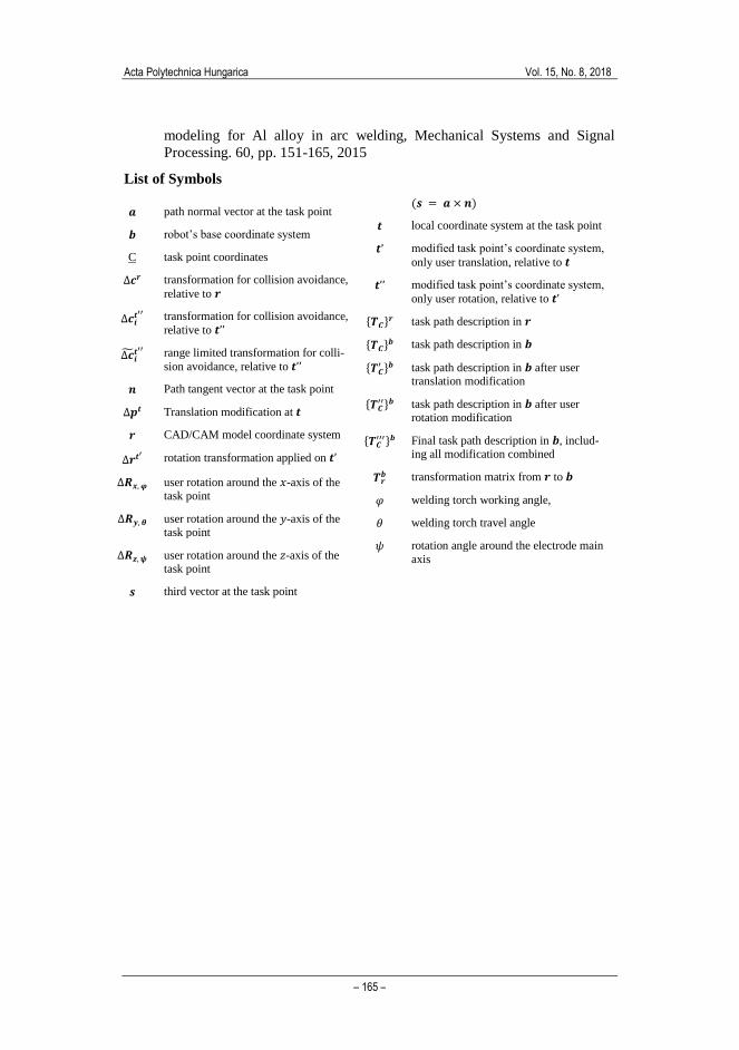
List of Symbols
𝒂 path normal vector at the task point
𝒃 robot’s base coordinate system
C task point coordinates
∆𝒄𝒓 transformation for collision avoidance,
relative to 𝒓
∆𝒄𝒊𝒕′′
transformation for collision avoidance,
relative to 𝒕’’
∆�̃�𝒊𝒕′′
range limited transformation for colli-
sion avoidance, relative to 𝒕’’
𝒏 Path tangent vector at the task point
∆𝒑𝒕 Translation modification at 𝒕
𝒓 CAD/CAM model coordinate system
∆𝒓𝒕′ rotation transformation applied on 𝒕’
∆𝑹𝒙, 𝝋 user rotation around the 𝑥-axis of the task point
∆𝑹𝒚, 𝜽 user rotation around the 𝑦-axis of the task point
∆𝑹𝒛, 𝝍 user rotation around the 𝑧-axis of the task point
𝒔 third vector at the task point
(𝒔 = 𝒂 × 𝒏)
𝒕 local coordinate system at the task point
𝒕’ modified task point’s coordinate system,
only user translation, relative to 𝒕
𝒕’’ modified task point’s coordinate system,
only user rotation, relative to 𝒕’
{𝑻𝑪}𝒓 task path description in 𝒓
{𝑻𝑪}𝒃 task path description in 𝒃
{𝑻𝑪′ }𝒃 task path description in 𝒃 after user
translation modification
{𝑻𝑪′′}𝒃 task path description in 𝒃 after user
rotation modification
{𝑻𝑪′′′}𝒃 Final task path description in 𝒃, includ-
ing all modification combined
𝑻𝒓𝒃 transformation matrix from 𝒓 to 𝒃
𝜑 welding torch working angle,
𝜃 welding torch travel angle
𝜓 rotation angle around the electrode main
axis