surface mining reclamation approaches to bond … · larry barbula senior analyst ... asst. water...
TRANSCRIPT
O F G E N E R A L I N T E R E S T
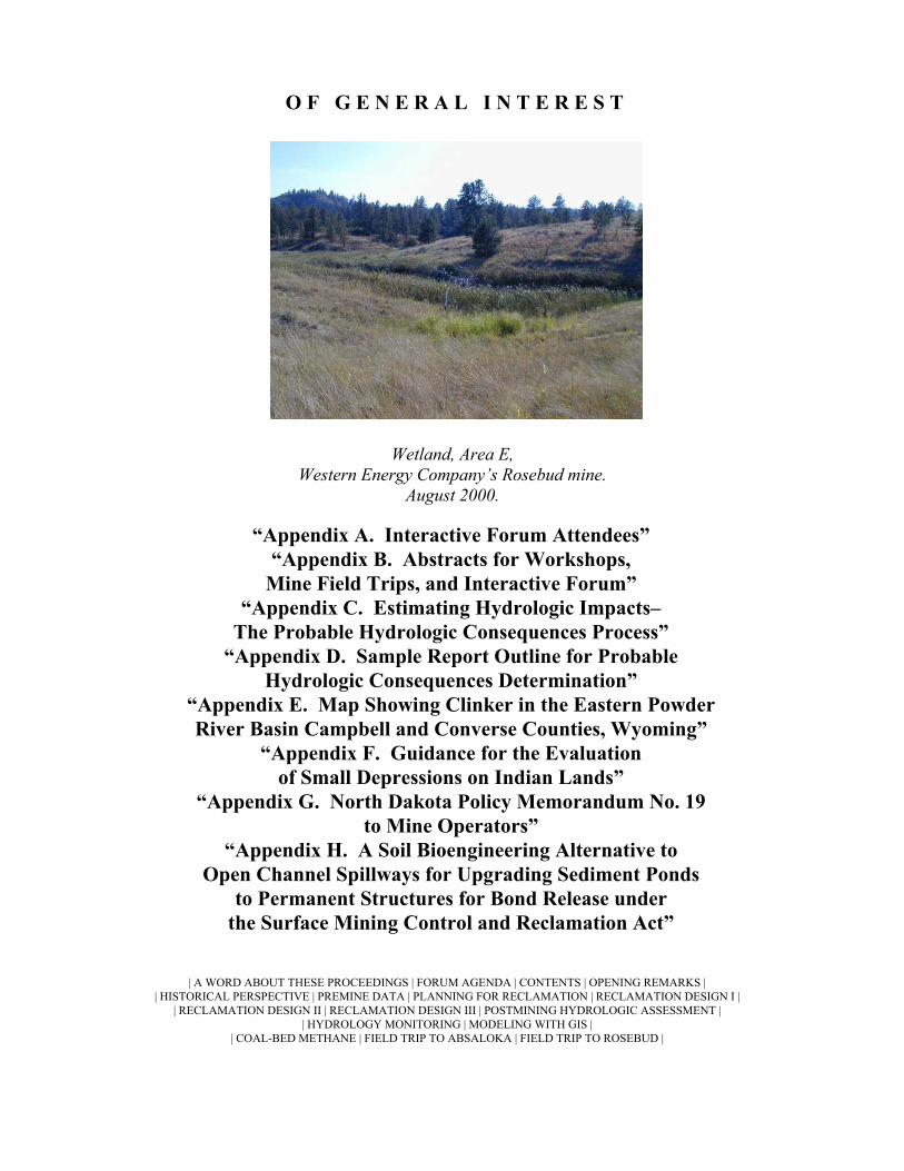
Wetland, Area E, Western Energy Company’s Rosebud mine.
August 2000.
“Appendix A. Interactive Forum Attendees” “Appendix B. Abstracts for Workshops,
Mine Field Trips, and Interactive Forum” “Appendix C. Estimating Hydrologic Impacts–
The Probable Hydrologic Consequences Process” “Appendix D. Sample Report Outline for Probable
Hydrologic Consequences Determination” “Appendix E. Map Showing Clinker in the Eastern Powder River Basin Campbell and Converse Counties, Wyoming”
“Appendix F. Guidance for the Evaluation of Small Depressions on Indian Lands”
“Appendix G. North Dakota Policy Memorandum No. 19 to Mine Operators”
“Appendix H. A Soil Bioengineering Alternative to Open Channel Spillways for Upgrading Sediment Ponds
to Permanent Structures for Bond Release under the Surface Mining Control and Reclamation Act”
| A WORD ABOUT THESE PROCEEDINGS | FORUM AGENDA | CONTENTS | OPENING REMARKS | | HISTORICAL PERSPECTIVE | PREMINE DATA | PLANNING FOR RECLAMATION | RECLAMATION DESIGN I |
| RECLAMATION DESIGN II | RECLAMATION DESIGN III | POSTMINING HYDROLOGIC ASSESSMENT | | HYDROLOGY MONITORING | MODELING WITH GIS |
| COAL-BED METHANE | FIELD TRIP TO ABSALOKA | FIELD TRIP TO ROSEBUD |

A P P E N D I X A.
I N T E R A C T I V E F O R U M A T T E N D E E S

Jim Albano Minerals Resource Specialist BLM - Montana State Office 500 Southgate Dr. Billings, Montana 59107
~~~~~~~~~ ~~~~~~~~~~ Tel: (406) 896-5111 Fax: (406) 896-5292
Leonard Ballek Vice President, Marketing Bitterroot Restoration, Inc. 445 Quast Lane Corvallis, Montana 59828-9406
~~~~~~~~~ ~~~~~~~~~~ Tel: (406) 961-4991 Fax: (406) 961-4626
Pat Baumann Kennecott Energy Company Antelope Coal Company 505 S. Gillette Ave. Caller Box 3008 Gillette, Wyoming 82717-3008 ~~~~~~~~~ ~~~~~~~~~~ Tel: (307) 464-2555 Fax: (307) 464-0824
Jim Berg Water Quality/Waste Management Basin Electric Power Cooperative Environmental Department 1717 East Interstate Avenue Bismarck, North Dakota 58501 ~~~~~~~~~ ~~~~~~~~~~ Tel: (701) 223-0441 Fax: (701) 255-5144
Mike Anderson GIS Analyst University of Kentucky Biosystems & Agricultural Engineering Dept. Lexington, Kentucky 40506-0276 ~~~~~~~~~ ~~~~~~~~~~ Tel: (859) 257-8803
Larry Barbula Senior Analyst Wyoming DEQ, LQD District III 1043 Coffeen Avenue, Suite D Sheridan, Wyoming 82801 ~~~~~~~~~ ~~~~~~~~~~ Tel: (307) 672-6488 Fax: (307) 672-2213
Lawrence Begay Reclamation Specialist III Navajo Nation Minerals Office of Surface Mining P.O. Box 3900 Window Rock, Arizona 86515 ~~~~~~~~~ ~~~~~~~~~~ Tel: (520) 871-7099 Fax: (520) 871-6457
Phil Berry Reclamation Administrator Transalta Centralia Mining Company 913 Big Hanaford Rd. Centralia, Washington 98531
~~~~~~~~~ ~~~~~~~~~~ Tel: (360) 330-8168 Fax: (360) 330-8168
A-2

Alan Best Principal Analyst B&G Systems, Inc. P. O. Box 302 Flagstaff, Arizona 86001
~~~~~~~~~ ~~~~~~~~~~ Tel: (520) 213-0370 Fax:(520) 213-0372
Peter Bierbach BLM - Montana State Office Branch of Planning & Biological Res. P. O. Box 36800 Billings, Montana 59101 ~~~~~~~~~ ~~~~~~~~~~ Tel: (406) 896-5033 Fax:(406) 896-5293
Tim Bozorth BLM - Montana State Office Hydrologist P. O. Box 36800 Billings, Montana 59101 ~~~~~~~~~ ~~~~~~~~~~ Tel: (406) 896-5041 Fax:(406) 896-5293
Luke Buckley Information Systems Support Sp Montana Bureau of Mines & Geology (MBMG) Montana Tech. 1300 W. Park St., Main Hall 322 Butte, Montana 59701-8997 ~~~~~~~~~ ~~~~~~~~~~ Tel: (406) 496-4336 Fax: (406) 496-4677
Alex Bulltail, Sr. Asst. Water Resources EPA/Water Resources P. O. Box 159 Crow Agency, Montana 59022 ~~~~~~~~~ ~~~~~~~~~~ Tel: (406) 638-2962 Fax: (406) 638-7250
David Bickel Environmental Scientist North Dakota Public Service Commission Reclamation Div. State Capitol Bldg., 13th Fl. 600 E. Boulevard Ave. Bismarck, North Dakota 58505-0165 ~~~~~~~~~ ~~~~~~~~~~ Tel: (701) 328-2249 Fax: (701) 328-2410
Richard Bonine President Horizon Resource Management P. O. Box 1784 Gallup, New Mexico 87305-1784 ~~~~~~~~~ ~~~~~~~~~~ Tel: (505) 726-0175 Fax: (505) 863-1951
Dale Brown Western Water Consultants, Inc. 1849 Terra Avenue Sheridan, Wyoming 82801-6112
~~~~~~~~~ ~~~~~~~~~~ Tel: (307) 672-0761 Fax: (307) 674-4265
Nicholas Bugosh Sr. Hydrologist San Juan Coal Co. SJCC - La Plata Mine P. O. Box 210 La Plata, New Mexico 87418
~~~~~~~~~ ~~~~~~~~~~ Tel: (505) 598-2803 Fax: (505) 598-2899
Paul Burley General Manager EDM, Inc. 208 N. Broadway, Suite 350 Billings, Montana 59101 ~~~~~~~~~ ~~~~~~~~~~ Tel: (406) 254-8570 Fax: (406) 256-7123
A-3

Georgia Cash Support Group Supervisor Wyoming DEQ, LQD Herschler Bldg., 3rd Fl. West 122 West 25th Street Cheyenne, Wyoming 82002 ~~~~~~~~~ ~~~~~~~~~~ Tel: (307) 777-7047 Fax: (307) 777-5864
Richard O. Clausen Environmental Monitoring Tech. Westmoreland Resources, Inc. P. O. Box 449 Hardin, Montana 59034
~~~~~~~~~ ~~~~~~~~~~ Tel: (406) 342-5404 Fax: (406) 342-5401
Chance Cole Farrell Cooper Mining Co. 6001 S. Zero St. Ft. Smith, Arizona 72903
~~~~~~~~~ ~~~~~~~~~~ Tel: (501) 646-4366 Fax: (501) 646-3220
Michael Davis Environmental and Construct. Supr. Canyon Fuel Company, LLC SUFCO Mine 397 South 800 West Salina, Utah 84654 ~~~~~~~~~ ~~~~~~~~~~ Tel: (435) 286-4421 Fax: (435) 286-4499
Edmond G. Deal, Ph.D. Director and State Geologist Montana Bureau of Mines & Geology Montana Tech. of the University of Montana 1300 West Park Street Butte, Montana 59701-8997 ~~~~~~~~~ ~~~~~~~~~~ Tel: (406) 496-4180 Fax: (406) 496-4451
Rick Chancellor Administrator Wyoming DEQ Land Quality Division Herschler Bldg., 122 W 25th St. Cheyenne, Wyoming 82002 ~~~~~~~~~ ~~~~~~~~~~ Tel: (307) 777-7046 Fax: (307) 634-0799
John Cochran Supr. Environmental Affairs Peabody Western Coal Company Black Mesa Mine P. O. Box 650 Kayenta, Arizona 86033 ~~~~~~~~~ ~~~~~~~~~~ Tel: (520) 677-5018 Fax: (520) 677-5058
Dave W. Darby Reclamation Spec./Geohydrology Utah Div. of Oil, Gas & Mining 1594 West N. Temple, Suite 1210 P. O. Box 145801 Salt Lake City, Utah 84114-5801 ~~~~~~~~~ ~~~~~~~~~~ Tel: (801) 538-5341 Fax: (801) 359-3940
Doug Davison Hydrologist Knife River Corp. P. O. Box 39 Beulah, North Dakota 58523
~~~~~~~~~ ~~~~~~~~~~ Tel: (701) 873-4333 Fax: (701) 873-7784
Brad E. Dingee Sr. Hydrologist Peabody Group 1013 East Boxelder Caller Box 3034 Gillette, Wyoming 82717 ~~~~~~~~~ ~~~~~~~~~~ Tel: (307) 687-6932 Fax: (307) 687-6939
A-4

Phil Dinsmoor Mgr. Environmental & Mine Eng. Rag Coal West, Inc. Belle Ayr Mine P. O. Box 3039 Gillette, Wyoming 82717-3039 ~~~~~~~~~ ~~~~~~~~~~ Tel: (307) 687-3406 Fax: (307) 687-3400
Wayne R. Erickson President Habitat Management, Inc. 3571 E. Phillips Circle Littleton, Colorado 80122-3644 ~~~~~~~~~ ~~~~~~~~~~ Tel: (970) 225-6080 Fax: (970) 225-6990
Doyl M. Fritz, P.E. President WWC Engineering 1849 Terra Avenue Sheridan, Wyoming 82801
~~~~~~~~~ ~~~~~~~~~~ Tel: (307) 672-0761 Fax: (307) 674-4265
Joe Galetovic Technical Coordinator Office of Technology Transfer OSM- Western Regional Coordinating Center 1999 Broadway, Suite 3320 Denver, Colorado 80202-5733 ~~~~~~~~~ ~~~~~~~~~~ Tel: (303) 844-1448 Fax: (303) 844-1546
A. Robert Easter A. R. Easter, Inc. 7178 South Vine Circle East Centennial, Colorado 80122-1628
~~~~~~~~~ ~~~~~~~~~~ Tel: (303) 730-3933 Fax: (303) 730-3663
Kate Forsting Energy Laboratory P. O. Box 3258 Casper, Wyoming 82602
~~~~~~~~~ ~~~~~~~~~~ Tel: (1-888) 235-0515 Fax:(307) 234-1639
Willis L. Gainer Director OSM - Albuquerque Field Office Suite 1200 505 Marquette Ave., N.W. Albuquerque, New Mexico 87102 ~~~~~~~~~ ~~~~~~~~~~ Tel: (505) 248-5096 Fax: (505) 248-5081
Ronald J. Gehrke Civil Engineering Peabody Group P. O. Box 3034 Gillette, Wyoming 82717
~~~~~~~~~ ~~~~~~~~~~ Tel: (307) 687-6934 Fax: (307) 687-6939
A-5

Harv Gloe Regulatory Program Specialist Casper Field Office, OSM Federal Bldg. 100 East B Street, Room 2128 Casper, Wyoming 82601-1918
~~~~~~~~~ ~~~~~~~~~~ Tel: (307) 261-6542 Fax: (307) 261-6552
Rebecca Good Mining Engineer/Geologist BLM - Montana State Office P. O. Box 36800 Billings, Montana 59102
~~~~~~~~~ ~~~~~~~~~~ Tel: (406) 896-5080 Fax: (406) 896-5294
Doug Growitz Hydrologist OSM HDQ, TSD 1951 Constitution Ave., N.W., Room 254 Capitol Bldg. Mail Stop Washington, D.C. 20240 ~~~~~~~~~ ~~~~~~~~~~ Tel: (202) 208-2634 Fax: (202) 219-3276
Chris Hansen Environmental Coordinator Canyon Fuel Co., LLC HC 35, Box 380 Helper, Utah 84526 ~~~~~~~~~ ~~~~~~~~~~ Tel: (435) 448-2669 Fax: (435) 448-2632
Tom Golnar Surface Water Hydrologist Montana DEQ, Industrial & Energy Minerals Bureau
1520 East 6th Avenue P. O. Box 200901 Helena, Montana 59620-0901 ~~~~~~~~~ ~~~~~~~~~~ Tel: (406) 444-4976 Fax: (406) 444-1923
Mary Greene Hydrologist OSM, WRCC, PSD, TIPS 1999 Broadway, Suite 3320 Denver, Colorado 80202-5733
~~~~~~~~~ ~~~~~~~~~~ Tel: (303) 844-1400, ext. 1438
Fax: (303) 844-1538
Debra Haglund Sales/Marketing Dri-Water 50 Old Courthouse Square Santa Rosa, California 95404
~~~~~~~~~ ~~~~~~~~~~ Tel: (707) 528-9283 Fax: (707) 528-3391
Bill Harbrecht Environmental Supervisor Western Energy P. O. Box 99 Colstrip, Montana 59323 ~~~~~~~~~ ~~~~~~~~~~ Tel: (406) 748-5224 Fax: (406) 748-5202
A-6

Norman E. Hargis Manager Environmental Affairs Bridger Coal Co. Jim Bridger Mine P. O. Box 2068 Rock Springs, Wyoming 82902-2068 ~~~~~~~~~ ~~~~~~~~~~ Tel: (307) 382-9741 Fax: (307) 362-5330
Reg Hoff Reclamation Manager Big Sky Coal Co. - Peabody P. O. Box 97 State Highway 39 South Colstrip, Montana 59323 ~~~~~~~~~ ~~~~~~~~~~ Tel: (406) 748-5759 Fax: (406) 748-2028
John H. Hughes Senior Geologist Environmental Development & Mgmt. 208 N. Broadway, Suite 350 Billings, Montana 59101
~~~~~~~~~ ~~~~~~~~~~ Tel: (406) 254-8570 Fax: (406) 256-7123
Dennis R. James Staff Geologist Falkirk Mining Co. Falkirk Mine P. O. Box 1087 Underwood, North Dakota 58576 ~~~~~~~~~ ~~~~~~~~~~ Tel: (701) 442-5751 Fax: (701) 442-5288
Edward L. Heffern BLM Wyoming State Office WY-922 5353 Yellowstone Rd. P. O. Box 1828 Cheyenne, Wyoming 82003-1828
~~~~~~~~~ ~~~~~~~~~~ Tel: (307) 775-6259 Fax: (307) 775-6203
Roberta Hoy Support Group Prog. Principal Wyoming DEQ/LQD Herschler Bldg. 3W 122 W. 25th St. Cheyenne, Wyoming 82002 ~~~~~~~~~ ~~~~~~~~~~ Tel: (307) 777-5922 Fax: (307) 777-5864
Wade Irion Water Resources Engineer HKM Engineering, Inc. 700 Granite Tower Bldg. 222 N. 32nd St. P. O. Box 31318 Billings, Montana 59107 ~~~~~~~~~ ~~~~~~~~~~ Tel: (406) 656-6399 Fax: (406) 656-6398
Allen D. Jones Hydrologist Decker Coal Company 12 Lake Shore Drive P. O. Box 12 Decker, Montana 59025 ~~~~~~~~~ ~~~~~~~~~~ Tel: (406) 757-2561 Fax: (406) 757-2430
A-7

Donald G. Jones Computer Systems Analyst WWC Engineering, Inc. 107 E. 1st St. Gillette, Wyoming 82716
~~~~~~~~~ ~~~~~~~~~~ Tel: (307) 682-1880 Fax: (307) 682-2257
John Kern Kern Statistical Services, Inc. 415 NW Robert Street Pullman, Washington 99163
~~~~~~~~~ ~~~~~~~~~~ Tel: (509) 339-2489 Fax: (509) 339-2490
Tom Kohley Principal Beartooth Mapping, Inc. 114 S. Houser, Suite E P. O. Box 2075 Red Lodge, Montana 59068 ~~~~~~~~~ ~~~~~~~~~~ Tel: (406) 446-1007 Fax: (406) 446-1012
Larry Larson Environmental Engineer North Dakota Public Service Commission Reclamation Division, Dept. 408 State Capitol Bldg, 13th Fl. 600 E Boulevard Ave. Bismarck, North Dakota 58505-0480 ~~~~~~~~~ ~~~~~~~~~~ Tel: (701) 328-4779 Fax: (701) 328-2133
Greg Liebelt Environmental Engineer Western Energy Company P. O. Box 99 Colstrip, Montana 59323 ~~~~~~~~~ ~~~~~~~~~~ Tel: (406) 748-5129 Fax: (406) 748-5202
Tom Kaldenbach Environmental Protection Spec. Colorado Div. Of Minerals & Geology Room 215 1313 Sherman Street Denver, Colorado 80203-2273 ~~~~~~~~~ ~~~~~~~~~~ Tel: (303) 866-4923 Fax: (303) 832-8106
Karl Koehler Sr. Environmental Engineer Trapper Mining, Inc. P. O. Box 187 Craig, Colorado 81626 ~~~~~~~~~ ~~~~~~~~~~ Tel: (970) 824-4401 Fax: (970) 826-6136
Shirley Lahr Equal Opportunity Officer OSM-WRCC-EEO Suite 3320 1999 Broadway Denver, Colorado 80202-5733 ~~~~~~~~~ ~~~~~~~~~~ Tel: (303) 844-140 Fax: (303) 844-1522
Robert Liddle Hydrologist OSM - Knoxville Field Office 530 Gay St., Suite 500 Knoxville, Tennessee 37902
~~~~~~~~~ ~~~~~~~~~~ Tel: (865) 545-4103 Fax: (865) 545-4111
Brandon Little Elk Glenn Director Environmental Affairs, Crow Tribe P. O. Box 159 Crow Agency, Montana 59022 ~~~~~~~~~ ~~~~~~~~~~ Tel: (406) 638-2962 Fax: (406) 638-7250
A-8

Bonnie Lovelace Chief, Water Protection Bureau Montana DEQ 1520 East 6th Ave., P. O. Box 200901 Helena, Montana 59620-0901 ~~~~~~~~~ ~~~~~~~~~~ Tel: (406) 444-4969 Fax: (406) 444-1374
Jerry Maio Planning-Development Engineer InterWest Mining Pacificorp 201 S. Main St., Suite 2000 Salt Lake City, Utah 84140 ~~~~~~~~~ ~~~~~~~~~~ Tel: (801) 220-4834 Fax: (801) 220-4725
James McGill Hydro-geologist HKM Engineering, Inc. 131 Crestline Dr. P. O. Box 31318 Billings, Montana 59107 ~~~~~~~~~ ~~~~~~~~~~ Tel: (406) 656-6399 Fax: (406) 656-6398
Marvin R. Miller, Ph.D. Assistant Director Montana Bureau of Mines and Geology, Montana Tech. of the U. of Mont. 1300 West Park Street Butte, Montana 59701-8997 ~~~~~~~~~ ~~~~~~~~~~ Tel: (406) 496-4155 Fax: (406) 496-4451
Randall Mills Mining Engineer OSM 1951 Constitution Ave., N.W. Washington, D.C. 20240 ~~~~~~~~~ ~~~~~~~~~~ Tel: (202) 208-2928 Fax: (202) 219-3276
John J. Mahoney, Ph.D. Associate Geochemist Hydrologic Consultants, Inc. of Colorado 143 Union Blvd., Suite 525 Lakewood, Colorado 80228 ~~~~~~~~~ ~~~~~~~~~~ Tel: (303) 969-8033 Fax: (303) 969-8357
Angela McDannel Groundwater Hydrologist Dept. of Environmental Quality IEMB P. O. Box 200901, 1520 E, 6th Ave. Helena, Montana 59620-0901 ~~~~~~~~~ ~~~~~~~~~~ Tel: (406) 444-4991 Fax: (406) 444-1923
Joe Meyer Soil Scientist/Hydrologist BLM - Casper Field Office 2987 Prospector Dr. Casper, Wyoming 82604
~~~~~~~~~ ~~~~~~~~~~ Tel: (307) 261-7641 Fax: (307) 261-7587
Scott L. Miller, P.G. Hydrologist 609 Circle Dr. Rapid City, South Dakota 57702
~~~~~~~~~ ~~~~~~~~~~ Tel: (605) 343-2178 Fax: (307) 332-7726
Bob Montgomery Environmental Manager Western Energy Company P. O. Box 99 Colstrip, Montana 59323-0099 ~~~~~~~~~ ~~~~~~~~~~ Tel: (406) 748-5186 Fax: (406) 748-5181
A-9

Sam Montoya Environmental Supr. Pittsburg & Midway Coal Co. York Canyon Mine Complex P. O. Box 100 Raton, New Mexico 87740-0100 ~~~~~~~~~ ~~~~~~~~~~ Tel: (505) 445-6016 Fax: (505) 445-6009
Darrel Myran Vice President - Operations Westmoreland Resources, Inc. P. O. Box 449 Hardin, Montana 59034-0449 ~~~~~~~~~ ~~~~~~~~~~ Tel: (406) 342-5241 Fax: (406) 342-5401
Jesse Noel, P.E. Environmental/Mining Eng. Western Energy Co. P. O. Box 99 Colstrip, Montana 59323
~~~~~~~~~ ~~~~~~~~~~ Tel: (406) 748-5199 Fax: (406) 748-5202
Dennis Oakley Environmental Engineer Energy West Mining Co. P. O. Box 310 Huntington, Utah 84528
~~~~~~~~~ ~~~~~~~~~~ Tel: (435) 687-4825 Fax: (435) 687-2695
Jeanne Osborne Engineering Technician Western Energy P. O. Box 99 Colstrip, Montana 59323 ~~~~~~~~~ ~~~~~~~~~~ Tel: (406) 748-5194 Fax: (406) 748-5202
Philip A. Murphree Engineer Powder River Coal Co. N Antelope/Rochelle Complex Caller Box 3035 Gillette, Wyoming 82717-3035 ~~~~~~~~~ ~~~~~~~~~~ Tel: (307) 464-4777 Fax: (307) 464-4706
Michael Nicklin, Ph.D., P.E. Nicklin Earth and Water, Inc. 670 Ferguson Rd., Suite 1 Bozeman, Montana 59718
~~~~~~~~~ ~~~~~~~~~~ Tel: (406) 582-0413 Fax: (406) 582-0449
Jim O'Hara Coal Program Manager New Mexico Energy, Minerals & Nat. Resources Dept., Mining & Minerals Div.
2040 S. Pacheco St. Santa Fe, New Mexico 87505 ~~~~~~~~~ ~~~~~~~~~~ Tel: (505) 827-1174 Fax: (505) 827-7195
Mathew P. Oommen Sr. Mining Engineer Marston & Marston 13515 Barrett Parkway Dr. Suite 260 Ballwin, Missouri 63021 ~~~~~~~~~ ~~~~~~~~~~ Tel: (314) 984-8800 Fax: (314) 984-8770
Tom J. Osborne Principal Hydrologist Hydro Solutions, Inc. P. O. Box 80866 Billings, Montana 59108-0866 ~~~~~~~~~ ~~~~~~~~~~ Tel: (406) 655-9555 Fax: (406) 655-0575
A-10

Guy V. Padgett Director OSM/Casper Field Office Federal Bldg., Room 2128 100 East B Street Casper, Wyoming 82601-1918 ~~~~~~~~~ ~~~~~~~~~~ Tel: (307) 261-6550 Fax: (307) 261-6552
Tom Patton Hydrogeologist, Program Mgr. Montana Bureau Mines & Geology (MBMG)
Montana Tech, Main Hall 1300 W. Park St. Butte, Montana 59701-8997 ~~~~~~~~~ ~~~~~~~~~~ Tel: (406) 496-4153 Fax: (406) 496-4343
Warren Phillips Hydrogeologist MCS Environmental 5562 Alloy South Missoula, Montana 59808 ~~~~~~~~~ ~~~~~~~~~~ Tel: (406) 728-7755
David N. Poelstra Laboratory Manager Inter-Mountain Labs, Inc. 555 Absaraka Sheridan, Wyoming 82801 ~~~~~~~~~ ~~~~~~~~~~ Tel: (800) 828-1407 Fax: (307) 672-9845
Bob Postle Ecologist OSM WRCC PSD 1999 Broadway, Suite 3320 Denver, Colorado 80202-5733 ~~~~~~~~~ ~~~~~~~~~~ Tel: (303) 844-1400, ext.1469
Fax: (303) 844-1538
Tom Parker Director of Consulting Bitterroot Restoration, Inc. 445 Quast Lane Corvallis, Montana 59828
~~~~~~~~~ ~~~~~~~~~~ Tel: (406) 961-4991 Fax: (406) 961-4626
William M. Peterson Geologist BNI Coal, Ltd. 2360 35th Ave., S.W. Center, North Dakota 58530
~~~~~~~~~ ~~~~~~~~~~ Tel: (701) 794-8734 Fax: (701) 794-3125
Wynn Pippin Energy Laboratories 1120 S. 27th St. Billings, Montana 59101
~~~~~~~~~ ~~~~~~~~~~ Tel: (406) 252-6325 Fax: (406) 252-6069
Russ Porter Reclamation Specialist Albuquerque Field Office/OSM 505 Marquette, N.W., Suite 1200 Albuquerque, New Mexico 87102 ~~~~~~~~~ ~~~~~~~~~~ Tel: (505) 248-5070 Fax: (505) 248-5081
Debbie Pretty Paint Petroleum Engineering Technician Crow Tribe P. O. Box 159 Crow Agency, Montana 59022 ~~~~~~~~~ ~~~~~~~~~~ Tel: (406) 638-2197 Fax: (406) 638-2274
A-11

Michael J. Price P. O. Box 853 Moab, Utah 84532
~~~~~~~~~ ~~~~~~~~~~ Tel: (435) 259-0052
Shawn Reddish Research Assistant Montana Bureau of Mines & Geology 1300 N. 27th St. Billings, Montana 59101
~~~~~~~~~ ~~~~~~~~~~ Tel: (406) 657-2630 Fax: (406) 496-4451
Phil Reinholtz Hydrologist OSM WRCC PSD 1999 Broadway, Suite 3320 Denver, Colorado 80202-5733 ~~~~~~~~~ ~~~~~~~~~~ Tel: (303) 844-1463, ext. 1463
Fax: (303) 844-1538
Gene Robinson Reclamation Specialist OSM/Casper Field Office 100 East "B" Street Federal Bldg., Room 2128 Casper, Wyoming 82601-1918
~~~~~~~~~ ~~~~~~~~~~ Tel: (307) 261-6340 Fax: (307) 261-6552
Leonard Raymond Mine Engineer BHP Navajo Coal Co. P. O. Box 1717 Fruitland, New Mexico 87416 ~~~~~~~~~ ~~~~~~~~~~ Tel: (505) 598-3268 Fax: (505) 598-3361
Steve Regele Reclamation Supervisor Montana DEQ Industrial & Energy Minerals Bureau Coal Program
Airport Industrial Park, Bldg. IP-9 Billings, Montana 59105-1978 ~~~~~~~~~ ~~~~~~~~~~ Tel: (406) 247-4433 Fax: (406) 247-4440
Pat Risner Environmental Coordinator BHP Navajo Mine P. O. Box 1717 Fruitland, New Mexico 87416 ~~~~~~~~~ ~~~~~~~~~~ Tel: (505) 598-3201 Fax: (505) 598-3361
Herb Rolfes Hydrologist Dept. of Environmental Quality IEMB - Reclamation Division P. O. Box 200901 1520 E. 6th Ave. Helena, Montana 59601-0901 ~~~~~~~~~ ~~~~~~~~~~ Tel: (406) 444-1516 Fax: (406) 444-1923
A-12

Alan Rolston Community Organizer Northern Plains Resource Council 2401 Montana Ave., No. 200 Billings, Montana 59101-2336
~~~~~~~~~ ~~~~~~~~~~ Tel: (406) 248-1154 Fax: (406) 248-2110
Stephan A. Schroeder, Ph.D. Environmental Scientist North Dakota Public Service Com., Reclamation Div.
Dept. 408 Capitol Bldg., 13th Floor 600 East Boulevard Avenue Bismarck, North Dakota 58505-0480 ~~~~~~~~~ ~~~~~~~~~~ Tel: (701) 328-3403 Fax: (701) 328-2133
Mike Shea Sr. Scientific Specialist Western Energy P. O. Box 99 Colstrip, Montana 59323 ~~~~~~~~~ ~~~~~~~~~~ Tel: (406) 748-5189 Fax: (406) 748-5202
Lance Sigismond Associate Engineer Crow Tribal Minerals P. O. Box 159 Crow Agency, Montana 54022
~~~~~~~~~ ~~~~~~~~~~ Tel: (406) 638-2192 Fax: (406) 638-2274
Eric W. Sandberg Environmental Coordinator Thunder Basin Coal Co., LLC Black Thunder Mine P. O. Box 406 Wright, Wyoming 82732 ~~~~~~~~~ ~~~~~~~~~~ Tel: (307) 464-2338 Fax: (307) 464-2313
Chuck A. Semborski Environmental/Geologic Supr. Energy West Mining Company Technical Services P. O. Box 310 Huntington, Utah 84528
~~~~~~~~~ ~~~~~~~~~~ Tel: (435) 687-4720 Fax: (435) 687-2695
Mary Siemsglusz Marston & Marston 13515 Barrett Pkwy. Dr. Suite 260 Ballwin, Missouri 63021 ~~~~~~~~~ ~~~~~~~~~~ Tel: (314) 984-8800 Fax: (314) 984-8770
Ted Smith Senior Hydrologist Peabody Western Coal Co. Western Division P. O. Box 625 Kayenta, Arizona 86033 ~~~~~~~~~ ~~~~~~~~~~ Tel: (520) 677-5011 Fax: (520) 677-5083
A-13

Rich Spang Western Energy Co. P. O. Box 99 Colstrip, Montana 59323
~~~~~~~~~ ~~~~~~~~~~ Tel: (406) 748-5114 Fax: (406) 748-5202
Judd Stark Reclamation Specialist Montana DEQ Airport Business Park Billings, Montana 59105 ~~~~~~~~~ ~~~~~~~~~~ Tel: (406) 247-4438 Fax: (406) 247-4440
Brenda Steele Senior Hydrologist OSM WRCC PSD 1999 Broadway, Suite 3320 Denver, Colorado 80202-5733 ~~~~~~~~~ ~~~~~~~~~~ Tel: (303) 844-1400, ext. 1459
Fax: (303) 844-1538
Robert R. Stowe Sr. Environmental Eng., CPG Rag Coal West, Inc., Belle Ayr Mine P. O. Box 3039 Gillette, Wyoming 82717-3039
~~~~~~~~~ ~~~~~~~~~~ Tel: (307) 687-3412 Fax: (307) 687-3470
Michael Suflita, P.E. Sr. Reclam. Hydrologist Utah Div of Oil, Gas and Mining 1594 West N. Temple, Suite 1210 P. O. Box 145801 Salt Lake City, Utah 84114-5801 ~~~~~~~~~ ~~~~~~~~~~ Tel: (801) 538-5259 Fax: (801) 359-3940
Richard Spotts Pres., Principal Eng./Hydrologist Water & Earth Technologies, Inc. 2900 South College Avenue Suite 3D Fort Collins, Colorado 80525-2562 ~~~~~~~~~ ~~~~~~~~~~ Tel: (970) 225-6080 Fax: (970) 225-6990
Martin W. Stearns Kennecott Energy Co. Caller Box 3009 Gillette, Wyoming 82717
~~~~~~~~~ ~~~~~~~~~~ Tel: (307) 685-6124 Fax: (307) 687-6058
Robert Garrett Stewart Mining Engineer Crow Tribe P. O. Box 159 Crow Agency, Montana 59022 ~~~~~~~~~ ~~~~~~~~~~ Tel: (406) 638-2192 Fax: (406) 638-2274
John R. Stucker Mining Engineer Navajo Nation Minerals Office of Surface Mining P. O. Box 3900 Window Rock, Arizona 86515 ~~~~~~~~~ ~~~~~~~~~~ Tel: (520) 871-6464 Fax: (520) 871-6457
Gregory O. Sweetser Mining Supervisor Wyo-Ben, Inc. P. O. Box 1072 Greybull, Wyoming 82426
~~~~~~~~~ ~~~~~~~~~~ Tel: (307) 765-4446 Fax: (307) 765-2664
A-14

Gary E. Taylor Sr. Environmental Engineer Canyon Fuel Co., LLC HC 35, Box 380 Helper, Utah 84501
~~~~~~~~~ ~~~~~~~~~~ Tel: (435) 448-2620 Fax: (435) 448-2632
Mike Thomas Reclamation Specialist Bitterroot Restoration 445 Quast Lane Corvallis, Montana 59828
~~~~~~~~~ ~~~~~~~~~~ Tel: (406) 961-4971 Fax: (406) 961-4626
Jason Todd Mining Engineer Decker Coal P. O. Box 12 Decker, Montana 59025 ~~~~~~~~~ ~~~~~~~~~~ Tel: (406) 757-2561
Dick Turpin Coordinator/Land Services Kennecott Energy, Jacobs Ranch Mine 505 S. Gillette Ave. Gillette, Wyoming 82718
~~~~~~~~~ ~~~~~~~~~~ Tel: (307) 685-6112 Fax: (307) 687-6058
Mark Taylor Sr. Analyst/geologist Wyoming DEQ, District III, LQD Suite D 1043 Coffeen Ave. Sheridan, Wyoming 82801 ~~~~~~~~~ ~~~~~~~~~~ Tel: (307) 672-6488 Fax: (307) 672-2213
John Tinger Civil Engineer U.S. EPA Engineering and Analysis Div. 401 M Street, S.W. (4303) Washington, D.C. 20005 ~~~~~~~~~ ~~~~~~~~~~ Tel: (202) 260-4992 Fax: (202) 260-7185
Kenneth Toineeta Cartographer Westmoreland Resources, Inc. P. O. Box 449 Hardin, Montana 59034 ~~~~~~~~~ ~~~~~~~~~~ Tel: (406) 342-5241 Fax: (406) 342-5401
Wayne Van Voast Chief, Research Div. Montana Bureau of Mines and Geology Montana College of Mineral Science and Technology
1300 W. Park Street Butte, Montana 59701-8997 ~~~~~~~~~ ~~~~~~~~~~ Tel: (406) 496-4169 Fax: (406) 496-4451
A-15

Allan Vesely Surface Reclamation Specialist BIA P. O. Box 1750 Crownpoint, New Mexico 87313
~~~~~~~~~ ~~~~~~~~~~ Tel: (505) 871-5932 Fax: (520) 871-5943
Brent Wahlquist Regional Director OSM - Western Regional Coordinating Center
1999 Broadway, Suite 3320 Denver, Colorado 80202-5733
~~~~~~~~~ ~~~~~~~~~~ Tel: (303) 844-1400, ext. 1401
Fax: (303) 844-1522
Steve Welch Chief, Industrial & Energy Minerals Bureau, Montana DEQ Permitting and Compliance Div. P. O. Box 200901 1520 E. 6th Ave. Helena, Montana 59620-0901 ~~~~~~~~~ ~~~~~~~~~~ Tel: (406) 444-4964 Fax: (406) 444-1923
Paul Williams Sr. Project Hydrologist Hydrologic Consultants, Inc., of Colorado 143 Union Boulevard, Suite 525 Lakewood, Colorado 80228 ~~~~~~~~~ ~~~~~~~~~~ Tel: (303) 969-8033 Fax: (303) 969-8357
Linda Wagner Programs Coordinator Office of Technology Transfer OSM - Western Regional Coordinating Center
1999 Broadway, Suite 3320 Denver, Colorado 80202-5733 ~~~~~~~~~ ~~~~~~~~~~ Tel: (303) 844-1450 Fax: (303) 844-1546
Richard C. Warner Associate Extension Professor University of Kentucky, Biosystems and Agricultural Engineering Dept.
Room 217 128 Agricultural Eng. Bldg. Lexington, Kentucky 40506-0276 ~~~~~~~~~ ~~~~~~~~~~ Tel: (606) 257-3000 Fax: (606) 257-5671
John Wheaton Hydrogeologist Montana Bureau of Mines & Geology 1300 North 27th Street Billings, Montana 59101
~~~~~~~~~ ~~~~~~~~~~ Tel: (406) 657-2629 Fax: (406) 657-2633
Pam Wilson Energy Laboratory P. O. Box 3258 Casper, Wyoming 82602
~~~~~~~~~ ~~~~~~~~~~ Tel: (1-888) 235-0515 Fax:(307) 234-1639
A-16

Chris Yde Wildlife Biologist/Veg. Spec. Montana DEQ, Industrial & Energy Minerals Bureau
1520 E. 6th Ave. P. O. Box 200901 Helena, Montana 59620-0901 ~~~~~~~~~ ~~~~~~~~~~ Tel: (406) 444-4967 Fax: (406) 444-1923
Andy Young Hydrologist BHP - Navajo Coal Co. New Mexico Coal, Navajo Mine P. O. Box 1717 Fruitland, New Mexico 87416
~~~~~~~~~ ~~~~~~~~~~ Tel: (505) 598-3303 Fax: (505) 598-3361
A-17

A P P E N D I X B.
A B S T R A C T S F O R W O R K S H O P S, M I N E F I E L D T R I P S, A N D
I N T E R A C T I V E F O R U M

This appendix consists of abstracts for a number of the presentations contained within these proceedings. In addition, it includes abstracts for two presentations that were part of the interactive forum but that are not contained within the proceedings. These two are:
“Ground Water on a Platter: Serving Data on the World-Wide Web from the Montana Ground-Water Information Center”
“The History of Gillette Area Ground-Water Monitoring Organization”
All presentations for which the Office of Surface Mining and its collaborators hold abstracts are printed in red in the table of contents listing. Page forward through this appendix (or, within contents, click on presentation titles printed in red) to access these abstracts in the order in which they are listed in contents. Click on individual of the titles listed immediately above to access those abstracts.
B-2
Graphic Analysis of Ground-Water Responses
David Bickel1 and Dennis R. James2
ABSTRACT
The well hydrograph, which is a plot of water-level elevation against time, is a common tool in ground-water hydrology. Expanding hydrographs by means of additional data on the X and Y axes is being done increasingly, because the mind visualizes comparisons between time series plots and other data, and these comparisons can be added to charts. The added data are typically: hydrostratigraphy, well-construction details, events, system control plots, and plots of other variables. Automated production of hydrographs in Excel with Visual BASIC routines allows rapid production of hundreds of plots for timely response monitoring and database validation. The database-validation approach allows well and aquifer properties to be integrated into a database structure, taking more account of user perspective than do traditional approaches.
Traditional graphic models such as structural contour and potentiometric surface maps often do not clearly convey pertinent geohydrologic information; expanded hydrographs easily validate well and hydrostratigraphic data for use in more informative graphic models. However, the hydrograph is more than a handmaiden to spatial modeling. Expanded hydrographs and spatial models are complementary, in that spatial models can show detail and trends through space while hydrographs can better show detail and system dynamics through time. For purposes of final bond release, graphic analysis can provide effective evaluation of ground-water responses to mining.
Paper Presented at the Interactive Forum on Surface Mining Reclamation Approaches to Bond Release: Cumulative Hydrologic Impact Assessment and Hydrology Topics for the Arid and Semi-Arid West
1 Environmental Scientist, Reclamation Division, North Dakota Public Service Commission, 600 E. Boulevard Avenue, Department 408, Bismarck, North Dakota 58505
2 Staff Geologist, Falkirk Mining Company, P. O. Box 1087, Underwood, North Dakota
B-3
58576

Determining Soil Conservation Service Curve-Runoff Numbers for Mineland Conditions
Stephan A. Schroeder, Ph.D.3
ABSTRACT
The curve-number (CN) method, developed by the U.S. Department of Agriculture’s Natural Resource Conservation Service (formerly known as the Soil Conservation Service [SCS]) is the most commonly used procedure for estimating runoff amount from rainfall. This method takes into account the hydrologic soil-cover complex, as well as antecedent moisture and rainfall amounts, in order to estimate the amount of runoff. Soil texture and its effects on infiltration and hydraulic conductivity distinguish the four hydrologic soil-cover complexes. The three antecedent moisture conditions (AMC) are based upon the 5-day rainfall amount preceding the time of estimation. For premine conditions, direct runoff can be estimated on the basis of CN values–these have been derived and are given in various tables of estimates of CN values–in conjunction with a figure showing rainfall versus direct runoff by CN value. Little data have been developed for overburden and spoil. However, North Dakota data suggest that CN values in the low to mid-90's are common for finer textured overburden and spoil. Coarser-textured materials would most likely have somewhat lower CN values. For reclaimed soil conditions from approximately 40 rainfall simulation plots, the estimated CN value from field data was within ±10 of the estimated SCS CN 86 percent of the time for AMC I and 99 percent of the time for AMC III conditions. These results indicate that the CN method may be used on reclaimed minelands with a fairly high degree of reliability.
Paper Presented at the Interactive Forum on Surface Mining Reclamation Approaches to Bond Release: Cumulative Hydrologic Impact Assessment and Hydrology Topics for the Arid and Semi-Arid West
3 Environmental Scientist, Reclamation Division, North Dakota Public Service Commission, 600 E. Boulevard Avenue, Department 408, Bismarck, North Dakota 58505
B-4

Climate, Bond Release, and the Concept of Minimum Liability Periods
David Bickel4
ABSTRACT
The Palmer Drought Severity Index (PDSI) is an index to moisture balance that has significant value as a compilation of baseline and bond-release data that may be compared for purposes of determining climatic variability, planning, preparing probable hydrologic consequences assessments, quantifying abnormally dry or wet conditions, separating climatic and mining effects, and evaluating vegetative stability and permanence. Data sets are readily available from Internet sites for monthly and annual periods and in long runs. The PDSI correlates well with reclamation-related environmental variables, and multi-century reconstructed annual PDSI are available for the United States, allowing long-term assessment of climatic patterns. The structure of the index makes analysis of intensity, duration, and frequency of wet and dry periods easy, and climatic cycles can be identified with spectral analysis. The PDSI correlates well with time-series records of plant growth and water resources related to mine reclamation. Its advantages for climatic assessment include its wide use, the availability of its data, and its structure. These advantages make evaluation of the duration, intensity, and periodicity of events relatively easy. The 10-year minimum liability period has become an unquestioned cornerstone of the Surface Mining Control and Reclamation Act (SMCRA), which was intended to test the stability and permanence of reclamation. The body of SMCRA-based regulation has assumed this function, and exposing reclamation to climatic variation is apparently the remaining rationale for requiring a minimum liability period. Altering SMCRA is not a realistic option, but a logical modification to the minimum-liability-period requirement would be to allow the termination of liability after reclamation results from the set of SMCRA-based practices in a region have demonstrated stability and permanence, through variations in drought and wetness, in the timeframe of high frequency cycles in the regional climate.
Paper Presented at the Interactive Forum on Surface Mining Reclamation Approaches to Bond Release: Cumulative Hydrologic Impact Assessment and Hydrology Topics for the Arid and Semi-Arid West
4 Environmental Scientist, Reclamation Division, North Dakota Public Service Commission, 600 E. Boulevard Avenue, Department 408, Bismarck, North Dakota 58505
B-5
Alluvial Valley Floors: Reclamation Bond-Release Criteria
Richard A. Chancellor5
ABSTRACT
For an alluvial valley floor (AVF) that is removed and subsequently reclaimed during the mining and reclamation process, performance standards are tied to the essential hydrologic functions of the AVF. The essential hydrologic functions are defined in the permit application through baseline soils, vegetation, and hydrologic studies. Coal-bed methane development has impacted and will continue to impact the environment, making it difficult to determine the “natural” premine essential hydrologic functions and postmine reclamation success.
Paper Presented at the Interactive Forum on Surface Mining Reclamation Approaches to Bond Release: Cumulative Hydrologic Impact Assessment and Hydrology Topics for the Arid and Semi-Arid West
5 Administrator, Wyoming Department Environmental Quality, Land Quality Division, 122 West 25th Street, Cheyenne, Wyoming 82002
B-6

Assessing Sedimentation and Landform Stability in Reclaimed Areas Using Baseline Sediment Data
Collected in Receiving Streams
H.T. Smith6 and Alan Best7
ABSTRACT
The stream-monitoring program at the Black Mesa and Kayenta coal mines in northeastern Arizona has been conducted from 1980 to the present. A principal thrust of the monitoring program has been to document background suspended sediment/solids levels in the principal washes transecting the coal-lease areas. The sediment-rating curves developed from the data collected are to be used as the standard against which sediment yields from reclaimed areas will be compared and watershed models calibrated.
Nonparametric statistical techniques were applied to the tons-per-day sediment versus flow data to derive best-fit regression lines to the data, assign prediction intervals around the data, and screen the data for outliers. Confidence-limit tests comparing the medians and slopes for the regression lines among the stream monitoring sites indicate that the sediment data, regardless of the wash, are from the same population. This fact strongly suggests there is an excess of available (potentially erodible and transportable) sediment in each of the stream watersheds. Thus, for any flow range, the mass of sediment transported is only limited by flow energy, not sediment availability. This has significant implications for bond release, approximate-original-contour criteria, and stability assessments for coal-mine reclamation in the Southwest.
Paper Presented at the Interactive Forum on Surface Mining Reclamation Approaches to Bond Release: Cumulative Hydrologic Impact Assessment and Hydrology Topics for the Arid and Semi-Arid West
6 Peabody Western Coal Company, Western Division, P. O. Box 625, Kayenta, Arizona 86033
7 B&G Systems, Inc., P. O. Box 302, Flagstaff, Arizona 86001
B-7
Wyoming Cumulative Hydrologic Impact Assessment and Coal-Bed Methane
Scott L. Miller8
ABSTRACT
Cumulative hydrologic impact assessments (CHIA’s) are prepared in Wyoming by the Wyoming Department of Environmental Quality (DEQ), Land Quality Division. A CHIA is prepared for new permit applications, permit amendments, and certain permit modifications to determine whether a mining operation has been designed to prevent material damage to the hydrologic balance. Coal-bed methane (CBM) development in the Powder River Basin has become a major issue between surface owners and subsurface mineral-rights owners. Currently, 23 of 37 surface coal mines in Wyoming are located in northeast Wyoming in the Powder River Basin. CBM development and coal mines both affect the hydrologic system and, where these two industries are in close proximity, impact areas may overlap. Wyoming DEQ has regulatory jurisdiction over coal mines but no jurisdiction with the CBM industry. At present, DEQ is addressing the issue of how to evaluate coal-mine impacts to the hydrologic system in areas where CBM impacts coexist.
Paper Presented at the Interactive Forum on Surface Mining Reclamation Approaches to Bond Release: Cumulative Hydrologic Impact Assessment and Hydrology Topics for the Arid and Semi-Arid West
8 Hydrogeologist, Wyoming Department of Environmental Quality, Land Quality Division, 250 Lincoln Street, Lander, Wyoming 82520
B-8

OSM’s CHIA: Black Mesa/Kayenta Mines
Phillip Reinholtz and Brenda A. Steele9
ABSTRACT
The Federal Office of Surface Mining (OSM) completed a cumulative hydrologic impact assessment (CHIA) for the Black Mesa/Kayenta mines in 1989. This CHIA provided the technical basis for the hydrology portions of OSM’s Black Mesa environmental impact statement (EIS). The Black Mesa/Kayenta mines are operated by Peabody Western Coal Company (Peabody) and cover an area of 101.3 square miles of Hopi and Navajo Tribal land in northeastern Arizona. The two mines produce about 12 million tons of coal annually. Coal from the Kayenta mine is dedicated to the Navajo Generating Station and is transported by railroad. Coal from the Black Mesa mine is dedicated to the Mohave Generating Station and is transported by slurry pipeline. Peabody uses about 3,900 acre-feet per year of N- and D-Aquifer water for its Black Mesa coal slurry pipeline operations. The N-Aquifer is also the main drinking water source for the area. To develop its CHIA, OSM had to delineate cumulative impact areas, define baseline conditions, identify hydrologic concerns, develop material-damage criteria, and analyze cumulative hydrologic impacts. OSM identified hydrologic concerns primarily through the EIS scoping process and meetings with the Hopi and Navajo Tribes. The major hydrologic concerns identified were potential impacts to the N-Aquifer from pumping for the slurry pipeline. The four N-Aquifer hydrologic concerns identified in the CHIA are (1) structural stability owing to reduction of the potentiometric head; (2) degradation of water quality owing to increased migration of water from the D-Aquifer; (3) reduction of the N-Aquifer, spring-discharge rate owing to alteration of the potentiometric surface; and (4) reduction of alluvial-flow rates owing to reduction of N-Aquifer discharge to the alluvium. Quantitative material-damage criteria were developed for each of these concerns. OSM concluded that none of the projected impacts exceeded the material-damage criteria. Peabody and the U.S. Geological Survey (USGS) are conducting ongoing monitoring of the N-Aquifer. These two entities have also developed computer models to evaluate drawdown impacts on the N-Aquifer from mining and from the local communities’ water usage. OSM regularly reviews and analyzes information collected by Peabody and the USGS to ensure that material damage to the N-Aquifer from mining has not occurred.
Paper Presented at the Interactive Forum on Surface Mining Reclamation Approaches to Bond Release: Cumulative Hydrologic Impact Assessment and Hydrology Topics for the Arid and Semi-Arid West
9 Hydrologists, Office of Surface Mining, 1999 Broadway, Suite 3320, Denver, Colorado 80202-5733
B-9

Recharge from Clinker in the Powder River Basin
Edward L. Heffern10
ABSTRACT
Over the past 3 million years, thick Tertiary coal beds in the Powder River Basin (PRB) have burned naturally, baking and collapsing the overburden to produce clinker–hardened, reddened, highly fractured rocks that now overlie the coal ash. Being more erosion resistant than unbaked strata, clinker persists during downwasting to form caprock up to 200 feet thick. High permeability and infiltration rates enable the 1,600 mi2 of clinker in the PRB to store large amounts of rainfall and snowmelt and protect them from evaporation. These unconfined clinker aquifers have transmissivities of 1,000 to 1,000,000 ft2/day and storativities of 0.1 to 0.3. Peak flows in clinker-dominated drainages are attenuated and water is discharged gradually to streams during periods of lower flow. Springs that emerge from the base of clinker form the headwaters of several perennial streams.
Plateaus capped by clinker on the west, north, and east flanks of the PRB recharge ground water both in the clinker and in unbaked strata downdip. In the Rochelle Hills of Wyoming, clinker recharges coal, overburden, and spoil aquifers downdip to the west. Some mines encounter inflow from large saturated clinker bodies updip, where water is dammed against the face of the less permeable coal. Ground water in clinker varies from 200 to 10,000 mg/L of total dissolved solids. Quality is better in well-drained areas, where soluble ash has dissolved away, and poorer where water has ponded along a coal contact.
Paper Presented at the Interactive Forum on Surface Mining Reclamation Approaches to Bond Release: Cumulative Hydrologic Impact Assessment and Hydrology Topics for the Arid and Semi-Arid West
10 Geologist, Mineral Program Operations, Department of the Interior, Bureau of Land Management, P. O. Box 1828, Cheyenne, Wyoming 82003
B-10

Use of a Local Ground-Water Model to Predict Relative Impacts of the Life-of-Mine Plan
for Rosebud Area D, Near Colstrip, Montana
Use of a Regional Ground-Water Model to Predict Relative Impacts of Life-of-Mine Plans
for Rosebud Area C, Near Colstrip, Montana
Michael Nicklin, Ph.D, P.E.11 and Greg Liebelt12
ABSTRACT
Western Energy Company (WECO) started coal-mining activities in areas near Colstrip, Montana, in 1982. A long-term, ground-water-monitoring database has been assembled since that time. An evaluation of this database provided an opportunity to quantify “cause-and-effect” relationships between historic mining and ground-water system response. It also provided an opportunity to refine predictions regarding relative impacts of pending future mining activities.
On behalf of WECO, Nicklin Earth & Water, Inc., evaluated the database that served as the basis for two different ground-water models. One model was constructed for Area C, west of Colstrip, and another was constructed for Area D, east of Colstrip. Nicklin Earth & Water used two different graphical user interfaces (GUI’s) in the modeling effort: Groundwater Modeling System and Groundwater Vistas. During the course of the modeling efforts, each of these GUI’s proved to have relative advantages over the other. By combining these tools in tandem, the overall modeling effort was enhanced.
An unusual consideration from a ground-water-modeling perspective is that the mining process involves replacing native formations with mining spoils possessing different hydraulic characteristics. Most modeling tools are not well-suited to directly incorporate such formation-parameter transitions. A procedure termed “adaptive parameterization” was used to address this issue.
11 Nicklin Earth & Water, Inc., 670 Ferguson Road, Suite 1, Bozeman, Montana 59718
12 Environmental Engineer, Western Energy Company, P. O. Box 99, Colstrip, Montana
B-11
59323

Both the Area-C and Area-D models were calibrated to steady-state and transient conditions. These calibrated models produced predictions that were consistent with historic observations for both drawdown and recovery at existing monitoring wells in mined areas. Nicklin Earth & Water used the models to predict future ground-water system responses associated with different mining-plan options.
Papers Presented at the Interactive Forum on Surface Mining Reclamation Approaches to Bond Release: Cumulative Hydrologic Impact Assessment and Hydrology Topics for the Arid and Semi-Arid West
B-12

Automatic Monitoring Systems for Reclamation Design
Richard C. Warner, Ph.D., Frank Camargo, and Michael Anderson13
ABSTRACT
Phase-III bond release may be based on vegetal establishment, hydrology, and sediment considerations. In the western United States, bond-release issues are an emerging concern that is actively being discussed and addressed in formulating regulatory guidelines. Discussions often address trade-offs between monitoring and modeling. Monitoring is needed for model assessment, calibration, and verification. The key components are rainfall, runoff, and sediment. Other monitored weather factors, associated with evapotranspiration rates, may be needed for vegetal studies. The focus of this presentation is automatic data-acquisition systems that are used to record rainfall, runoff, and sediment concentration.
The presentation discusses three rainfall stations–the HOBO, the Davis, and the Campbell scientific stations–that vary in functionality, design, and price and that can easily be installed on a minesite. The HOBO station is the least expensive, but requires that data be downloaded in the field directly to a laptop or alternative hardware. The Davis station provides many more sensor options than the HOBO and enables wireless transmission of data via UHF, modem, or landlines. The Campbell scientific station, which is the most expensive of the three, provides research-quality meteorological information from a nearly unlimited selection of sensor packages. Campbell stations electronically transmit collected data in a variety of formats, including voice synthesizers, satellite, telephone modems, and spread-spectrum radios.
Accurate representation of large-watershed hydrology often requires monitoring streamflow during base-flow as well as high- and low-flow conditions. Use of stream- gaging stations is typically the preferred method to acquire continual streamflow data with minimal personnel input after installation. Automatic recording devices such as electronic data loggers record the stream stage at predetermined intervals or continuously in response to the level of a float or a pressure transducer inside a stilling well. Location of the gaging station requires investigation of several factors to determine the best possible site. The reach of channel should be between two large tributary or confluent streams. The key factor is a well-defined and stable stream reach that is (1) relatively straight up and downgradient from the station, (2) not likely to flood or overtop the bank, and (3) far enough away from any downstream backwater influences.
13 University of Kentucky, Biosystems and Agricultural Engineering Department, Room 217, 128 Agricultural Engineering Building, Lexington, Kentucky 40506-0276
B-13

As long as runoff from a watershed can be directed to a single discharge point, it can be monitored automatically through use of flumes and automatic stage recorders. Flumes are constructed in such a way that mathematical relationships exist whereby head of water can be translated in a flume-to-flow rate. Flumes come in many varieties and can measure a wide range of flows depending on their type and size. Trapezoidal flumes have an additional advantage in that they are flat-bottomed and, therefore, self-flushing. Recording flow is accomplished by attaching a stilling well to the flume by means of a small intake pipe. A pressure transducer senses the water pressure exerted by the head in the stilling well and sends a voltage impulse to a data logger that then translates the voltage into units of head (SI or English).
Sediment sampling is performed in conjunction with runoff monitoring by using an automatic sampling system such as those manufactured by ISCO, Inc., or American Sigma. The sampler intake tube can be mounted inside the flume, a stream, or a pipe. Systems are programmable for uniform or non-uniform sampling sequences, can be triggered to initiate sampling when liquid is detected at a user-specified level, and can store up to 24 sample bottles. The units are battery powered and, with the use of solar panels, can be left in the field with minimum maintenance. Data can be downloaded onto laptop computers when samples are retrieved, so the units do not need to be retrieved. Alternatively, turbidity sensors can be used.
Transmission of any sensor’s data can be accomplished using telephone modems, cellular telephone, radio telemetry, spread-spectrum radios, short-haul modems, or satellites. These telecommunication options are often viable alternatives to field technicians downloading data onsite.
Paper Presented at the Interactive Forum on Surface Mining Reclamation Approaches to Bond Release: Cumulative Hydrologic Impact Assessment and Hydrology Topics for the Arid and Semi-Arid West
B-14

Reclaiming Montana Ephemeral Channels and Associated Side Slopes in Lands Disturbed by Surface Mining
Herb Rolfes14 and Steve Regele15
ABSTRACT
Ephemeral channels are often the most commonly encountered and hydrologically important features to replace in reclaimed, arid landscapes. They are the foundations for postmine topographies, the designs of which require input from multiple and overlapping natural-resource disciplines. Despite this, reconstructed channels and side slopes all too often do not closely approximate premine dimensions. Channel-construction designs generally do not take account (by incorporation) the overall hydrologic significance of these features, nor do they demonstrate consideration of criteria regarding what is necessary to reestablish vegetative diversity and production, as well as wildlife habitat. Channels are often located along former haul roads; many fail to exhibit proper size and shape, fail to blend into side slopes, or fail to create a meandering pattern. Channels are frequently reclaimed as broad swales, even though they may be replacement features for coulees or small, incised channels. Although broad swales may become relatively stable once vegetation is established, the initial lack of vegetative cover, together with the absence of meanders, frequently results in severe erosion and undesirable hydrologic effects, including the formation of braided channels. In addition, when features such as coulees and small, incised channels are replaced with broad swales, the restoration of appropriate and diverse vegetation and wildlife habitat is limited. The value of replacement features–such as snow catchments that will hold and retain moisture and areas in which wildlife and livestock can take shelter from sun, wind, predation, and observation–is often lost when appropriate channel and side-slope features are not considered during reclamation.
Paper Presented at the Interactive Forum on Surface Mining Reclamation Approaches to Bond Release: Cumulative Hydrologic Impacts Assessment and Hydrology Topics for the Arid, Semi-Arid West
14 Surface-Water Hydrologist, Montana Department of Environmental Quality, Helena, Montana 59620-0901
15 Reclamation Program Supervisor, Montana Department of Environmental Quality, Billings, Montana 59105-1978
B-15

Sediment-Storage Design Considerations for Temporary Structures–SEDCAD and RUSLE
Richard C. Warner, Ph.D.16
ABSTRACT
The design volume for temporary sediment-control structures consists of two components: (1) storm water and (2) sediment storage. Input parameters to be considered are the size of the design storm, the functioning of the entire system of controls, the anticipated length of time that the temporary control is to be used, upgradient sediment production, and the frequency of sediment removal. There are many linkages among these design considerations. For example, a relatively small dedicated sediment-storage volume and a long period of exposure to high levels of upgradient sediment generation both require frequent sediment removal. The purpose of this paper is to explore these linkages, in quantitative terms, using the design and evaluation capabilities of both the Revised Universal Soil Loss Equation (RUSLE, version 1.06) and Sediment, Erosion, and Discharge by Computer Aided Design (SEDCAD, version 4). . Often, a system of sediment controls is used on a minesite. If the temporary control is not the most downgradient control and, therefore, is not subject to effluent requirements, it is the prerogative of design professionals to select a design storm that meets their needs. Storage of storm water generated from a 1- to 2-year design storm is quite reasonable for temporary controls. Spillways need to be designed for larger storm events. The reasoning behind using smaller design storms than those normally considered (i.e., the 10-year, 24-hour event) is that the controls are temporary and the vast majority of storms are small. To put this into perspective, consider that, in a 10-year period, approximately 80 to 90 percent of sediment generated will be from storms with return periods of 2 years or less. In addition, controls designed to contain the 2-year event will have a significant effectiveness on the first-flush sediment load generated from larger storms.
Maintenance (i.e., sediment clean-out) can be a major cost component. The designer needs to consider the type of control and location, especially with respect to roads or easy access points. Often, all diversions are designed as non-erodible channels based on a 10- year storm. Given such design criteria, the sediment-transport capability of smaller storms may very well result in significant deposition along the diversion in locations that are difficult to access.
16 Associate Extension Professor, University of Kentucky, Biosystems and Agricultural Engineering Department, Room 217, 128 Agricultural Engineering Building, Lexington, Kentucky 40506-0276
B-16

Sediment clean-out can only be accomplished in a cost-effective manner if sediment rather than soupy water is removed. Structural controls that have been designed with passive dewatering systems can readily accommodate efficient sediment removal. It may be most efficient to design sediment-control structures to function as a sediment-conveyance system to downgradient controls that are specifically designed to accommodate sediment removal. Alternatively, a slow release of low-concentration, sediment-laden waters to downgradient riparian areas can accomplish introduction of moisture for vegetal establishment and growth, ground-water recharge, and high overall sediment-trap efficiency.
This paper will present alternative sediment controls that illustrate design philosophies considering trade-offs among major design parameters.
Paper Presented at the Interactive Forum on Surface Mining Reclamation Approaches to Bond Release: Cumulative Hydrologic Impact Assessment and Hydrology Topics for the Arid and Semi-Arid West
B-17

OSM’s Guidance for Small Depressions on Indian Lands Mines
Willis Gainer17
ABSTRACT
The Office of Surface Mining (OSM) is the regulatory authority for coal-mining operations on Indian lands in the southwestern United States. Backfilling and grading operations at most mines on these lands offer opportunities to create or retain small depressions in backfilled areas. OSM regulations at 30 CFR 816.102(h) allow the construction of small depressions. Over the years, many questions–such as, for example, what types of small depressions can be authorized by the regulatory authority to remain–have arisen regarding the definition of small depressions. OSM believes that small depressions can serve important purposes for water retention, vegetation enhancement, and the creation of wildlife habitat. Currently, OSM is proposing guidance for the review and authorization of small depressions to answer many of the questions for Indian lands mines.
Paper Presented at the Interactive Forum on Surface Mining Reclamation Approaches to Bond Release: Cumulative Hydrologic Impact Assessment and Hydrology Topics for the Arid and Semi-Arid West
17 Director, Office of Surface Mining, Albuquerque Field Office, Suite 1200, 505 Marquette Avenue, NW, Albuquerque, New Mexico 87102
B-18
Proposed Effluent-Limitation Guidelines for the Coal-Mining Point-Source Category
William A. Teillard18 and John Tinger19
ABSTRACT
On April 11, 2000, the U.S. Environmental Protection Agency (EPA) proposed by Federal Register (65 FR 19440) to amend the current regulations for the coal-mining point-source category (40 CFR 434) by adding two new subcategories. EPA proposed to establish a new subcategory that would address preexisting discharges at coal-remining operations; it also proposed to establish a second new subcategory that would address drainage from coal-mining reclamation areas in the arid and semi-arid western United States. This proposed amendment would not otherwise change the existing regulations. EPA accepted public comment on the proposal until September 8, 2000.
Existing regulations establish effluent limitations for reclamation areas throughout the U.S., but require all such reclamation areas–regardless of climate, topography, or type of mine drainage (i.e., acid or alkaline)–to meet the same discharge limits. EPA is proposing a new western alkaline coal-mining subcategory to encourage the use of best management practices (BMP’s) to control erosion and sediment from reclamation areas in the arid and semi-arid regions of the western United States.
EPA believes there are unique environmental conditions in the arid West that are much different from those in other coal-mining areas. In arid regions, the natural vegetative cover is sparse, and rainfall is commonly received during localized, high-intensity, short-duration storms. These conditions contribute to flash-floods and turbulent flows that transport large amounts of sediment. Controlling sediment in areas that naturally contain large amounts of it can be difficult and can result in numerous impacts that harm aspects of the environment beyond water quality. These aspects can include disturbing the natural hydrologic balance, accelerating erosion, reducing ground-water recharge, reducing water availability, and impacting large areas of land for pond construction. To address such impacts, EPA is proposing a new subcategory that requires coal-mine operators to implement BMP’s so that postmined lands are reclaimed to approximately the natural conditions present prior to mining activities.
18 Director, Analytical Methods, U.S. Environmental Protection Agency, Engineering and Analysis Division, 401 M Street SW (4303), Washington, D.C. 20005
19 Civil Engineers U.S. Environmental Protection Agency, Engineering and Analysis Division, 401 M Street SW (4303), Washington, D.C. 20005
B-19

The proposed western alkaline coal-mining subcategory would regulate alkaline-mine drainage from reclamation areas in the arid and semi-arid West. This subcategory would not affect existing limitations for active mine wastewater. EPA proposes that a coal-mining operator must design and implement BMP’s to maintain the average annual sediment yield equal to or below premined, undisturbed conditions. This would ensure that natural conditions are maintained and would not allow a coal-mining operator to increase the discharge of sediment over natural conditions. To achieve these results, EPA would require that operators develop site-specific, sediment-control plans using established watershed modeling techniques.
Paper Presented at the Interactive Forum on Surface Mining Reclamation Approaches to Bond Release: Cumulative Hydrologic Impact Assessment and Hydrology Topics for the Arid and Semi-Arid West
B-20

Using RUSLE 1.06 to Estimate Soil Erosion by Water on Minelands
Stephan A. Schroeder, Ph. D.20
ABSTRACT
Many soil-erosion equations had been released over time before the release in 1965 of the Universal Soil Loss Equation (USLE), which used over 10,000 plot years of soil-loss data. An Agricultural Research Service group started in 1985 to modify the USLE based upon additional data that had become available. This resulted in the release of the Revised Universal Soil Loss Equation (RUSLE), version 1.02. Several modified versions of RUSLE have subsequently been released. In 1997, a working group under the auspices of the Office of Surface Mining in Denver was formed to modify RUSLE, version 1.04, for use on mined, construction, and reclaimed lands. This effort resulted in the release of RUSLE, version 1.06. This version has several advantages over both USLE and RUSLE, version 1.04, including updated city values for R and the abilities to account for rock fragments in the K and C factors and to define slope lengths in up to ten segments. RUSLE 1.06 also has the capability to compute sediment-delivery ratios that take account of factors such as terracing. Comparisons of RUSLE 1.06 to USLE and RUSLE 1.04 have indicated that RUSLE 1.06 has greatly improved the technology for estimating erosion from disturbed lands.
Paper Presented at the Interactive Forum on Surface Mining Reclamation Approaches to Bond Release: Cumulative Hydrologic Impact Assessment and Hydrology Topics for the Arid and Semi-Arid West
20 Environmental Scientist, Reclamation Division, North Dakota Public Service Commission, 600 E. Boulevard Avenue, Department 408, Bismarck, North Dakota 58505
B-21

Removing Sedimentation Ponds in North Dakota
Larry L. Larson21
ABSTRACT
In 1987, North Dakota regulatory agencies and the North Dakota mining industry coordinated the development of guidelines for the reclamation of sedimentation ponds at surface mines. The Reclamation Division of the North Dakota Public Service Commission and the Water Quality Division of the North Dakota State Department of Health, with industry input, have developed pond-removal guidelines to address the physical reclamation and subsequent release of water-quality discharge points. Reclamation of sedimentation ponds at surface mines in North Dakota has been completed under these guidelines. North Dakota has also developed a guideline for the final bond release of small areas of associated mining disturbance within a larger release tract.
Experience has shown that sedimentation ponds in North Dakota can be removed successfully, with subsequent release of bond amounts.
Paper presented at the Interactive Forum on Surface Mining Reclamation Approaches to Bond Release: Cumulative Hydrologic Impact Assessment and Hydrology Topics for the Arid and Semi-Arid West
21 Environmental Engineer, Reclamation Division, North Dakota Public Service Commission, 600 E. Boulevard Avenue, Department 408, Bismarck, North Dakota 58505
B-22

Using Chemical Data from Overburden Cores to Predict the Time Duration of Elevated Dissolved Solids
in Colorado Coal-Spoil Leachate
Tom Kaldenbach22
ABSTRACT
Prior to approving the release of a coal-reclamation bond for any given mine, a regulatory agency is required to predict “the probability of future” water pollution caused by the mine [30 CFR 800.40(b)(1)]. Cumulative hydrologic impact assessments also require predicting long-term hydrologic impacts caused by mining. One part of predicting the long-term potential for water pollution is the prediction of how long dissolved-solids concentrations in a spoil leachate will remain elevated above premining levels. Predicting these concentrations more than a few decades into the future is difficult given the less than 40-year historical record of hydrologic impacts from backfilled surface coal-mine pits.
A common approach to predicting the duration of elevated dissolved solids in coal spoil leachate is to perform a mass-balance analysis of the minerals that load the ground water as it flows through the spoil. A mass-balance analysis requires a good understanding of which minerals are the source of the loading, the chemical processes causing the loading, and the factors limiting the maximum concentration of solids. Rather than conducting a new mass balance analysis for each mine that is developed in Cretaceous rocks in Colorado, the Colorado Division of Minerals and Geology (DMG) applied a published analysis for one northwestern Colorado mine–Williams’s and Clark’s 1994 analysis of the Seneca II mine–at five other mines that have similar hydrogeology. The method involved simply comparing the pyrite content of overburden cores at a subject mine to the pyrite content in cores at the Seneca II mine, for which Williams and Clark had made duration predictions. Oxidation of pyrite is considered to be the main source of elevated dissolved solids at both the subject mines and the Seneca II mine. Colorado DGM adjusted the duration estimate for each subject mine to take account of the differences in annual precipitation at that mine as versus the Seneca II mine. Each duration estimate was reduced for piping in the spoil. As it did for the Seneca II mine, the method predicted durations of elevated solids in leachates lasting several hundred years.
The method is a new use of the overburden core data that have been in most mining permits since their original issuances. The method does not provide a precise prediction of duration, but can be expected to discriminate between durations of dissolved solids lasting a few decades and
22 Environmental Protection Specialist, Colorado Division of Minerals and Geology, 1313 Sherman Street, Room 215, Denver, Colorado 80202-2273
B-23

those measured in centuries. The method probably is not usable with respect to mines developed in Rocky Mountain coal beds younger than Cretaceous (for example, the Tertiary-aged Fort Union and Wasatch Formations in Wyoming, Montana, and North Dakota), because these mines have a different overburden/spoil mineralogy and structural history.
Paper Presented at the Interactive Forum on Surface Mining Reclamation Approaches to Bond Release: Cumulative Hydrologic Impact Assessment and Hydrology Topics for the Arid and Semi-Arid West
B-24

North Dakota Postmining Hydrologic Assessments
David Bickel23
ABSTRACT
A postmining hydrologic assessment (PHA) is a report that addresses hydrologic requirements–that is, requirements related to water resources rather than the management and reclamation of surface-water handling facilities on a mine–for final bond release. It is the final accounting of water-resources protection and reclamation for a mine area. Unlike the probable hydrologic consequences analysis and the cumulative hydrologic impact assessment, the PHA is primarily a descriptive, historical, and comparative analysis of existing water resources; it is not a predictive document. The rationale for the PHA grew out of a need to justify on hydrologic grounds the end of water-resources monitoring. When selected by a mine operator as an option to address hydrologic bond-release requirements, the PHA is submitted as a stand-alone revision to all affected mining permits. The PHA serves as a basic reference document that can be summarized in all bond-release applications, so that documentation related to small bond-release tracts does not have to repeat similar hydrologic information. Also, the PHA keeps the postmining water resources evaluation from being overlooked, fragmented, or made secondary to evaluations regarding vegetation and land-use requirements during the final bond-release process.
Paper Presented at the Interactive Forum on Surface Mining Reclamation Approaches to Bond Release: Cumulative Hydrologic Impact Assessment and Hydrology Topics for the Arid and Semi-Arid West
23 Environmental Scientist, Reclamation Division, North Dakota Public Service Commission, 600 E. Boulevard Avenue, Department 408, Bismarck, North Dakota 58505
B-25
Ground Water on a Platter: Serving Data on the World-Wide Web from the Montana
Ground-Water Information Center
Tom Patton24 and Luke Buckley25
ABSTRACT
The Montana Ground-Water Information Center (GWIC) serves as the central repository for ground-water and water-well information in Montana. GWIC databases include construction information for almost 165,000 wells; results for 21,000 water-quality analyses from 12,000 sites; drill-cuttings descriptions for more than 88,000 wells; more than 360,000 measured static water levels; and site-visit data for about 4,400 wells inventoried by the Ground-Water Characterization Program (GWCP) and other Montana Bureau of Mines Geology personnel. GWIC staff update the databases daily and service about 150 requests for information each month. GWIC data are available through its website (http://.mbmggwic.mtech.edu), which answers between 150 and 300 queries per weekday.
The GWIC website is the public access point for the GWIC databases and is designed to service routine queries ranging from those about specific wells to those for areas as large as townships. The site also offers GWCP study-area data sets, Ground-Water Assessment Atlas maps, and Ground-Water Assessment Open-File Reports. If the publicly available retrievals do not meet specific needs, GWIC personnel can provide almost any conceivable retrieval based on almost any field in the databases. Such specialized retrievals can be forwarded to users via e-mail or by file transfer protocol.
The retrieval options on the main GWIC menu can provide a reasonably complete baseline hydrogeologic data set. To obtain a data set, a GWIC user must choose a township and range and then select among “Well Completion,” “Lithology,” “Static Water Level,” “Inventory,” “Field Chemistry,” and “Water Quality Ions” reports. The user may then transfer water-well completion data, lithology data, field-measurement data, and water-quality data to his or her personal computer. These data can then be loaded into spreadsheets, filtered to meet specific
24 Hydrogeologist and Program Manager, Montana Bureau of Mines and Geology, Montana Tech of The University of Montana, 1300 West Park Street, Butte, Montana 59701
25 Information Systems Support Specialist, Montana Bureau of Mines and Geology, Montana Tech of The University of Montana, 1300 West Park Street, Butte, Montana 59701
B-26 �

needs, and made to become the basis for field work. Downloaded data fields can be easily exported from spreadsheets as “.dbf” or “.txt” files for import into ArcView or ArcInfo.
GWIC data have limitations. They can not reasonably be used to address certain site-specific questions, first because most of the location data (the data not ascribable to visited wells) are locations chosen by drillers or landowners and second because the descriptions themselves of materials provided by well drillers can be difficult to interpret (even though the general conditions of ground-water occurrence within chosen locations do generally emerge). Specific data sets such as those based on GWCP well inventories represent high-quality data; locations are highly accurate, and field measurements of water level, conductivity, pH, nitrate, and other parameters are available.
Paper Presented at the Interactive Forum on Surface Mining Reclamation Approaches to Bond Release: Cumulative Hydrologic Impact Assessment and Hydrology Topics for the Arid and Semi-Arid West
B-27

The History of the Gillette Area Ground-Water Monitoring Organization
Philip A. Murphree26 and Brad Dingee27
ABSTRACT
The Gillette Area Groundwater Monitoring Organization (GAGMO) was founded in 1980 by the operating mining companies of the southern Powder River Basin to serve as a data-gathering organization that would facilitate regional analyses of the area hydrology. Each member of GAGMO annually assembles hydrologic data, including water levels for coal, overburden, and backfill in the basin, as well as backfill water quality. The data from all of mines are then compiled into an annual report that shows them, along with potentiometric surface maps of the five sub-areas between the Buckskin mine at the north end of the basin to the Antelope mine at the south. Every 5 years, drawdown maps and other supplemental information are added to the report. These GAGMO reports are valuable to those wishing to study or understand the hydrology of the southern Powder River Basin. GAGMO has periodically sponsored educational or scientific forums; recently, it has provided data to and commentary on the various attempts by government agencies to model the area for coal-bed methane development.
Paper Presented at the Interactive Forum on Surface Mining Reclamation Approaches to Bond Release: Cumulative Hydrologic Impact Assessment and Hydrology Topics for the Arid and Semi-Arid West
26 Hydrologist, Powder River Coal Company, North Antelope/Rochelle Complex, GAGMO Chairman, 1999-2000, Caller Box 3035, Gillette, Wyoming 82717-3035
27 Senior Hydrologist, Peabody Group, 1018 East Boxelder, Caller Box 3034, Gillette, Wyoming 82717
B-28
A P P E N D I X C.
E S T I M A T I N G H Y D R O L O GI C I M P A C T S - T H E P R O B A B L E H Y D R O L O G I C
C O N S E Q U E N C E S P R O C E S S
ESTIMATING HYDROLOGIC IMPACTS: THE PROBABLE HYDROLOGIC �CONSEQUENCES (PHC) PROCESS
The PHC process is discussed in the following sections:
•� Introduction; •� Hydrologic Evaluation; •� Hydrologic Reclamation Plan; •� Probable Hydrologic Consequences Determination; and •� Monitoring.
INTRODUCTION
The PHC process consists of the following steps, repeated as many times as necessary to mitigate adverse impacts
•� Data collection; •� Characterization of the premining hydrologic balance; •� Prediction of mining disturbances; •� Design of measures to mitigate mining disturbances; and • Documentation of residual impacts to the hydrologic balance remaining after
implementation of mitigative measures.
The remaining unmitigated impacts must be documented in the PHC determination. This iterative PHC process is intended to reduce the predicted adverse impacts to the hydrologic balance to an acceptable level. A sample outline for the PHC determination is available for downloading.
The PHC process should consider:
•� The quantity and quality of both surface water and ground water; • The physical and chemical properties of the coal and overburden materials that
have the potential to affect water quality:
o Special features of the mining and reclamation operations potentially affecting water resources, including water treatment and handling facilities, diversions, sediment control measures, de-watering activities, etc.;
o Support facilities such as haul roads, storage areas, preparation plants, dragline erection areas, etc.
The process suggests a sequential approach starting with the definition of information needs. The types of information needed, however, not only rely heavily on baseline conditions but also on postmining reclamation objectives to be achieved and
C-2

characterization of the water resources that must be preserved to support those objectives. Therefore, the PHC process starts with a clear understanding of the intended postmining land uses. Hydrologic criteria necessary to support those water uses help define the information needs for the entire impact analysis.
Element (1) refers to defining information needs.
Element (2) refers to collecting baseline information which describes the hydrologic and geologic conditions that exist at the site to be mined. Emphasis should be placed on those characteristics defined in the first element that are critical to water uses.
Element (3) refers to the analysis of the baseline information collected to determine the nature and critical functions of the hydrologic system. The analysis helps to identify hydrologic units that may potentially be affected by the operation and to establish their pre-mining values. Both surface- and ground-water parameters should be considered and the level of analysis should be based on the complexity and variability of the hydrologic system on a seasonal basis, the importance of the water resource, and specific requirements of the RA.
Element (4) refers to planning the steps the applicant will take to minimize disturbance to the hydrologic balance within the permit area and prevent material damage outside the permit area. The Hydrologic Reclamation Plan should address impacts previously identified and should describe the measures planned to mitigate those impacts.
Element (5) defines the magnitude of impacts to be expected after the proposed preventive and remedial measures have been applied. This is considered to be the PHC determination which must make findings on:
1. Whether adverse impacts may occur to the hydrologic balance. 2. Whether acid- or toxic-forming materials are present that could result in the
contamination of surface- or ground-water supplies. 3. Whether the proposed operation may result in contamination, diminution, or
interruption of an underground or surface source of water within the proposed permit or adjacent areas which is used for domestic, agricultural, industrial, or other legitimate purposes.
4. What impact the proposed operation will have on: o (a) sediment yield from the disturbed area; o (b) acidity, total suspended and dissolved solids, and other important
water-quality parameters of local impact; o (c) flooding or streamflow alteration; o (d) ground- and surface-water availability; and o (e) other characteristics as required by the RA.
Iterations of impact analysis and mitigation design continue until all impacts to the hydrologic balance within the permit and adjacent areas have been minimized and material damage outside the permit area has been prevented. If, during this process,
C-3

analyses indicate adverse impacts from a surface mine on a water source being used for any legitimate purpose, then the applicant must provide information on alternate sources of water. These additional steps are represented by the Supplemental Information (4a) and Alternative Water Source Information (4b) elements.
Element (6) refers to development of ground- and surface-water monitoring plans to measure actual impacts to those resources resulting from the mining operation. These plans focus on parameters identified earlier as critical to maintaining water uses in support of reclamation objectives for postmining land uses.
HYDROLOGIC EVALUATION
Identifying Impacts
Although the PHC determination is a projection of residual impacts after implementation of preventive and mitigative measures, the types of impacts anticipated to result from mining are identified in the initial iterations of the PHC process. These anticipated impacts are the focus of the detailed preventive and mitigative hydrologic planning described in the hydrologic reclamation plan.
Ground-Water Quantity
The ground-water system comprises the water bearing strata and confining beds that lie beneath the Earth's surface. The system serves both as a water storage unit and as a conduit through which water is transmitted from recharge areas to discharge areas. An understanding of the rate, direction, and overall pattern of ground-water movement in aquifer systems encountered in coal regions is essential for predicting impacts to groundwater quantity. Both surface and underground mining have the potential to disrupt and permanently alter the physical characteristics of aquifer systems through:
1. Reduction of ground-water availability through the removal of aquifers in the overburden or removal of the coal seam aquifer itself;
2. � Reduction of ground-water storage capacity as measured by water-level declines; 3. � Changes in ground-water flow directions; 4. � Alteration of stream baseflow conditions; 5. � Increased ground-water recharge through spoil and fractured bedrock; 6. Creation of aquifers with significantly different hydraulic properties (spoil
aquifers and aquifers affected by subsidence associated with underground mining);
7. � De-watering of shallow aquifers related to underground mining.
These alterations, in turn, may affect the hydraulic characteristics of aquifers, potentiometric heads, the rate of discharge from springs and wells, the direction of flow within and between aquifers, the types and rates of chemical reactions occurring within the ground-water system, and ultimately, the total quantity and chemical composition of the ground water moving through the permit area.
C-4
Seasonal variations in ground-water quantity in the permit and adjacent areas may be defined by measurements of water levels in observation wells, changes in spring discharges, and discharge of surface-water baseflow. These measurements, in addition to a water users inventory, are important components of the mine site investigation which the applicant should conduct in order to assess baseline conditions.
The hydrologic complexity of a site and the significance of the ground-water issues usually dictate an appropriate predictive method. The applicant should select a method that accurately reflects site conditions and that has been proven effective. It may be adequate to express ground-water quantity impacts qualitatively, alone or in combination with varying degrees of quantitative analyses.
Hydrologic models ranging from simple empirical equations to complex numerical computer solutions may be used for estimating ground-water impacts. Models must be calibrated with site-specific data or data representative of the site. Extrapolation of data from an adjacent or nearby area to a permit area is acceptable when the similarity of the areas is established and information is available to justify the correlations. Generally, ground-water quantity predictions are made with analytical or numerical flow models.
Ground-Water Quality
The composition and concentration of substances dissolved in ground water depends on the biologic and chemical reactions occurring on the land surface and in the soil zone, and the mineral composition of the aquifers and confining beds through which the water moves. Prior to mining, the relationships governing the movement of water through the permit area and those affecting the chemical composition of the water are likely to be in a state of relative equilibrium, reflected in the existing baseline water quantity and quality regimes.
With the onset of mining, the surface- and ground-water hydrology of the area will be altered disrupting the existing equilibrium. From a hydrogeologic standpoint, the most disruptive forces are the removal of the coal seam and the fragmentation and spoiling of the overburden material. These processes result in the exposure of mineral surfaces to air and water and alter the water holding and transmitting characteristics of the geologic materials. The rates at which ground waters move through a permit area and the chemical composition of that water are therefore, subject to significant change.
Ground-water quality impacts resulting from mining activities usually involve changes in the concentration of existing constituents dissolved in the water and/or the addition of new chemical constituents mobilized by oxidation/reduction reactions in the spoil material. Increased mineral concentrations result from:
• Increases in surface area of exposed material, • Increased oxidation/reduction reactions in the disturbed materials,
C-5

• Increase in rate of recharge and movement of water through the spoil, • Increase in mineral solubility and mobilization due to Ph changes caused by pyrite
oxidation.
When the spoil materials become re-saturated after mining and a hydraulic gradient is reestablished across the disturbed area, water will begin moving through the spoil towards discharge zones. This water has the potential of becoming highly mineralized due to the chemical reactions occurring in the spoil. Additionally, ground water may become mineralized and contaminated from poor quality surface water percolating through the spoil and recharging the water table aquifer. Potential sources of contaminated surface water include acid drainage, pit pumpage and waste-water from coal processing plants.
Contaminant transport models are available for use in analyzing the movement, mixing, and chemical reactions of contaminated water through an aquifer system. Because ground-water flow is a major factor affecting the movement of pollutants, contaminant transport models are extensions of ground-water flow models.
Surface-Water Quantity
Streamflow at a particular site consists of ground water derived baseflow and surface runoff resulting from precipitation or snowmelt. Seasonal flow conditions refer to the fluctuation of flow over the course of a year. Peak discharges result from the addition to baseflow of surface runoff due to rainfall and snowmelt. Low flow refers to the minimum discharges during the year which are wholly composed of baseflow. For ephemeral streams, there is no baseflow component; their flows occur only in response to precipitation and snowmelt runoff.
Surface-water discharge parameters most often included in hydrologic analyses are peak and low-flow frequencies and mean flow values. Although seasonal flow conditions generally do not include values form instantaneous peak flows, the PHC determination should indicate the impact of the proposed operation on flooding or streamflow alteration. Therefore, some analysis of peak flows may be necessary. Generally, peak flows and flooding will be reduced during mining due to the increased infiltration capacity of the reclaimed area and the storage capacity of water-retention structures.
The following is a brief discussion of the various methods for analyzing surface flows. These methods may also be used for water-control structure designs.
Runoff volume is part of the information needed to characterize water resources. Runoff volume is calculated by subtracting losses (evapotranspiration and infiltration) from the amount of precipitation expected during a rainfall event. The amount of evapotranspiration is very small during a storm and can usually be neglected. Both empirical and physical methods are available for calculating infiltration. The most commonly used empirical methods are the Curve Number method, Index methods, and
C-6

Horton's equation. These involve simplified representations of the physical system and may produce large errors at a specific site.
Of the empirical methods, the Curve Number method is the most widely used. The method lumps all water losses except evapotranspiration into a single initial abstraction. It correlates rainfall runoff to soil type, land use, and hydrologic condition. This method was developed for designing water-control structures on croplands and is suited for mining design. Because it is not easily calibrated to actual watershed responses, it is not well suited to prediction of streamflows. However, the method is popular because it is relatively easy to use under a variety of field conditions, especially for watersheds where site specific data is not available.
Storm peaks are normally estimated either by deriving hydrographs or by direct methods. A hydrograph illustrates the variation of discharge rate over time at a specified location in a watershed and, as such, provides a measure of the potential for flooding or streamflow alteration as a result of mining. The hydrograph shape determines the timing and magnitude of the peak discharge and is a function of how rapidly runoff volume forms (excess rainfall) and of the conditions along the flow path (time of concentration).
A common method of developing hydrographs is based on unit-hydrograph theory. The unit hydrograph is traditionally defined as a hydrograph produced by a storm of constant rainfall intensity and duration containing one unit of runoff volume. It is based on the assumptions of linearity and constant time increments governing equations, and that the same unit-hydrograph can be used throughout the storm's duration. The literature contains numerous unit hydrograph shapes that have been developed and applied. Those most commonly used are the triangular hydrograph, Haan's dimensionless hydrograph and the double-triangle hydrograph. The techniques for developing and using these and other unit hydrographs to develop a site-specific runoff hydrograph can be found in most standard hydrology texts. The baseflow hydrograph must be added to the runoff hydrograph to obtain the hydrograph of the total discharge.
Direct methods estimate peak discharges without computation of a runoff hydrograph. They are generally simpler to use than the hydrograph procedure and may be in the form of empirical procedures or regionalized regression equations. The rational method, Cook's method, Bureau of Public Roads methods, TPM method, and the SCS TR55 method are examples of empirical procedures. In general, use of these methods involves using coefficients selected from tables, graphs, or charts in an equation. Accuracy depends on how closely the method represents the hydrologic system and results are difficult to verify.
Regionalized methods are usually in the form of regression equations in which the dependent variable is a flow characteristic, and watershed and climatic characteristics are independent variables. Stream channel dimensions have also been used as independent variables. Such equations are most frequently developed to provide the peak discharges of a specified frequency, but they can also be developed to provide mean discharges, low-flow discharges, and runoff volumes. The process of developing regression equations
C-7
also provides a statistical measure of the equation's accuracy (standard error of estimate). Regionalized regression equations have been developed to estimate peak discharges for all the coal-producing areas of the conterminous States.
A major shortcoming of direct methods of estimating discharges is that they usually represent relatively undisturbed watersheds. They are, however, useful for evaluating pre-mining streamflows and are, in many cases, preferable to the Curve Number method for this purpose.
The methods discussed above attempt to predict the hydrologic response of an area through empirical relationships or through greatly simplified expressions of hydrologic processes. Physical watershed models simulate watersheds mathematically by applying equations depicting several hydrologic processes over a geographical area. For surface runoff, a model might consider the effects of infiltration, evaporation, evapotranspiration, and interflow processes on the precipitation falling on a watershed. The stresses of mining can be incorporated into these models, and their effects can be evaluated at as many locations as desired. In theory, this approach should provide more accurate results than the empirical methods discussed above. Watershed models are not universally applicable and need to be tailored to the specific conditions of the area being analyzed.
Surface-Water Quality
Impacts to the quality of surface waters due to surface mining activities usually include changes in sediment loads, changes in Ph, and increases in trace metal and dissolved solids concentrations. The PHC determination therefore should include seasonal estimate of maximum and minimum concentrations and total loads of dissolved solids. In addition, predictions of seasonal concentrations of potentially deleterious trace metals, and sediment to be expected in runoff from disturbed areas should be provided as well as estimates of time necessary for these concentrations to reach equilibrium levels acceptable for the postmining land uses.
High concentrations of dissolved solids, suspended sediment, and metals can degrade the water quality potentially causing damage to the hydrologic balance and jeopardizing the approved postmining land uses. Irrigation water high in dissolved solids (salts) reduces crop yields and can corrode farm and industrial equipment. Waters high in trace elements such as boron, mercury, lead and selenium can be deleterious to plants and can also be toxic to livestock and wildlife. Waters having high trace metal concentrations have shown significant adverse health effects on humans, livestock, and wildlife. Furthermore, in some areas aquatic life may be adversely affected by increases in sediment and dissolved solids concentrations.
Acid mine drainage is a serious water quality problem especially in the Eastern and Mid-continental coal basins. Potentially harmful elements commonly associated with acid mine drainage include arsenic, boron, mercury, lead, zinc, cadmium, aluminum, copper, chromium, nickel, selenium and other trace elements.
C-8

Some methods for dealing with acid mine drainage problems are included later in this chapter and in the appendix on acid mine drainage. Although, acid mine drainage in the West is not as prevalent as in the East, pyritic conditions in western coals also produce environments of lowered Ph potentially resulting in increased mobilization of trace metals in the ground and surface waters.
During mining, and for some time following reclamation, many dissolved constituents can reach elevated levels from spoil due to the exposure of new mineral surfaces to air and water on an almost continual basis. Spoiling the overburden acts in two major ways to increase concentrations of dissolved solids and metals. First, overburden removal and spoiling increases the porosity of the material allowing more surface area of the materials to come into contact with air and water and increase the concentration of dissolved solids. Second, potential for oxidation of pyritic material and resultant acid mine drainage is increased. The rate at which this occurs is dependent on many physical factors. In the arid West, where precipitation is low and normally seasonal, this process could take hundreds of years. Therefore, predicting when all the pyritic material will be oxidized and the system will again approach equilibrium is problematic.
Once vegetation is established and disturbance of surface soil materials ends, the supply of minerals available at the land surface for solution and transport will normally decrease to premining levels. If erosion rates are higher than pre-mining levels, dissolved solids concentrations of surface runoff may remain at elevated levels for a longer period. If potentially toxic- or acid-forming materials are identified, the PHC should describe the steps to be taken during mining and reclamation to reduce exposure of this material to the atmosphere and contact with water in order to prevent development of acid mine drainage.
Methods are available for predicting concentrations of dissolved solids in surface runoff. These range from simple routing procedures to complex computer models which predict water, chemical, and sediment volumes and route them to various points in the stream system. A routing procedure is needed to combine the concentrations of surface- and ground-water components of flow in receiving streams.
Detailed, quantitative analyses in the PHC process are frequently unnecessary, especially for small sites in the East. However, for some of the large, western coal operations (permit areas of up to 100 square miles), numerical modeling for both quantity and quality is commonly utilized. The existing hydrologic data for a watershed may not be sufficient to calibrate a model or verify the credibility of the results. Depending on the complexity of the hydrologic system and the potential for adverse impacts to the hydrologic balance, additional baseline information may be required so that accurate PHC predictions can be made.
The disturbance of the land surface by mining and reclamation activities can significantly increase erosion and sediment yields. The PHC process should address impacts that the operation will have on sediment yield and on suspended solids concentrations of water draining from the permit area. Sediment yield is the volume of sediment that passes a
C-9
designated point over a unit period of time, usually one year. The sediment yield at 2 watershed outfall is usually less than the hill-slope and channel erosion rates occurring within the watershed because some of the eroded material is redeposited before it reaches the measurement point.
The impacts of mining on sediment yield can be evaluated in two phases: (1) impacts on the erosional characteristics of hill-slopes, and (2) impacts on sediment transport characteristics, including channel erosion. Hill-slope erosion rates are a function of precipitation, surface soil characteristics, hill-slope gradient and configuration, and vegetation type and density. Sediment transport rates depend upon the sediment characteristics (particle size and density) and streamflow characteristics, which, in turn, are functions of stream channel shape and gradient. Simply stated, for a given particle-size distribution and density of sediment material, a larger water discharge can carry more sediment, if more is available to be transported.
Sediment yield can be addressed either qualitatively or quantitatively. A qualitative approach should describe design plans for sediment-control structures and measures to be employed during mining and reclamation to control sediment yields. Commonly used measures are discussed in the section on hydrologic reclamation plan mitigation measures.
Methods for estimating sediment yields quantitatively generally fall into two categories:
1. those that estimate sediment yield directly, and 2. those that estimate erosion rates and then determine how much of the eroded
material is actually transported from the site.
The most widely used method of predicting soil erosion is the universal soil loss equation (USLE). The USLE is an empirical formula for predicting soil loss due to sheet-and- rill erosion. The original equation modeled the influence of rainfall intensity, soil erodibility, slope length, plot length, cropping and management practices, and supplemental erosion control measures.
The Revised Universal Soil Loss Equation (RUSLE) is a computer program developed by the U.S. Agricultural Research Service that can be used to compute the soil loss from disturbed and undisturbed sites. The program calculates values for the six erosion factors that were developed for the USLE. These are multiplied to give an estimate of annual soil loss. RUSLE is more applicable to surface-mine conditions and provides more accurate estimates of soil loss over a wider range of site conditions than the USLE. The program has been used on surface-mines to evaluate the effectiveness of sediment control measures.
Regionalized multiple regression equations have been developed for predicting annual sediment yields. These equations relate sediment yield to easily measured watershed parameters, such as maximum annual peak discharge, cover density, and watershed area.
C-10

These equations may not be directly applicable to predicting postmining sediment yields if parameter values are outside prescribed ranges.
HYDROLOGIC RECLAMATION PLAN
Minimizing Impacts
The objective of these mitigative measures is to minimize disturbance to the hydrologic balance within the permit area and to prevent material damage to the hydrologic balance outside the permit area.
A surface coal mining operation may affect the hydrologic balance of the permit and adjacent areas in the following general ways: (1) by changing the quantity of surface runoff from the disturbed areas, (2) by exposing un-weathered mineral surfaces and potentially toxic/acid-forming materials to weathering processes, and (3) by intercepting and modifying existing ground-water flow patterns and rates. These impacts may result in changes in the volumes and flow rates of both surface-and ground-water discharges, and in changes to acid, salt and sediment content of those discharges. Mitigation measures should attempt to prevent large changes or to provide suitable treatment when such changes are unpreventable.
Mitigation measures applied to coal mining situations most commonly deal with water quality impacts and control of surface runoff. Some mitigative techniques address both situations. It is more difficult to mitigate changes in the ground-water system.
Design of Mitigation
Toxic- and Acid-Forming Materials
A variety of methods is available for mitigating potential adverse impacts to surface- and ground-water quality resulting from the presence of toxic- and acid-forming materials.
One method is to selectively handle materials so that oxidation and leaching do not occur or are minimized. Toxic- or acid-forming materials can be placed under an adequate layer of nontoxic soil or spoil or inundated in a permanent impoundment so that oxidation is prevented. Depending on the volume of suitable materials available and the volume of available burial space, special handling may be a feasible method for dealing with all of the toxic- or acid-forming materials.
In some instances, alkaline material may be used as a neutralizing agent for acid-forming materials, and a blending of the materials during back-filling may prevent the formation of an acid leachate. The chemical makeup of the material present will determine whether it is placed above or below the water table during special handling. In either case, the elevation of the postmining water table will have to be estimated. It should be noted that in cases where re-saturation occurs primarily from local surface sources, submerging may
C-11

not preclude all oxidation because local infiltration may contain significant concentrations of dissolved oxygen.
Other methods of sealing toxic- and acid-forming materials are available, such as artificial barriers, and surface sealants like lime and gypsum. However, these methods are generally more expensive than special material handling techniques and require maintenance or reapplication. Clay, asphalt, or other inert barriers may be placed above the materials to prevent surface-water infiltration. Similar types of barriers may be placed around toxic materials to prevent infiltration by ground water. Unless the volume of material is relativ ely small, barriers are likely to be prohibitively expensive.
A different approach is treatment of unacceptable quality surface runoff through use of treatment ponds. Ponds for treating acid and toxic mine drainage should only be used during active mining as they require maintenance.
In cases where the mitigative measures will not result in surface or ground-water quality suitable for the postmining land use, the mining plan can still be designed to protect the hydrologic balance. Areas of toxic materials can be identified during pre- mining exploratory drilling and sampling programs. These areas can then be bypassed during mining.
Surface Water and Sediment Control
Sediment production is a function of runoff rates and the erodibility of soil materials. The more runoff there is and the faster it moves over a site, the more soil erosion that is likely to occur. Therefore, control of sediment production involves control of both runoff and erosion. Erosion rates generally increase when protective vegetation is removed and the surface soil materials are stirred up to expose finer particles to rain splash and running water. The basic means of reducing erosion and transport of sediment are to reduce the quantity and velocity of water moving through the site and to protect erodible soil particles from the water's erosive forces.
There are several basic approaches to reduce erosion and sediment loads caused by mining.
1. Expose the smallest possible area for the shortest possible time. Loss of vegetative cover and creation of steep slopes greatly increase soil loss, as do clearing, grubbing, and scalping. Erosion can be greatly reduced with judicious scheduling of mining operations. The initial soil disturbance should occur just ahead of the mining operations, and reclamation should be started as soon as possible after mining. Efficient scheduling also minimizes the need for stockpiles, another source of high sediment concentrations.
2. Keep detached soil close to its source. Soil detachment by raindrops initiates erosion. Prevention of soil detachment is the best method of erosion control. Soil stabilization techniques including re-vegetation, mulches, chemicals and structural measures help reduce raindrop impact and should be applied as soon as
C-12
practical after disturbance. Stabilization methods may not be appropriate during active mining, but are most useful for reclaiming disturbed areas.
3. Erosion impacts are minimal when detached soil is redeposited near its origin. Slowing runoff allows sediment to drop out of the flow. Designing reclamation to create slope gradients as flat as possible will assure low water velocities. Breaking long, steep slopes with benches or terraces, and contour furrowing are structural methods of reducing runoff velocities.
4. Runoff from undisturbed areas should be prevented from entering disturbed areas with properly designed up-gradient diversions. This minimizes the amount of water available to scour the erodible disturbed areas.
5. Prevent additional sediment from leaving permit area. The most common method for accomplishing this is by construction of sediment ponds or siltation structures. Alternate sediment control measures that are useful in specific situations include berms around the base of stockpiles, terraces, vegetative buffer zones (grass filters), check dams, and straw dikes. The objective of all these measures is to detain the runoff until some of the sediment can settle out.
Streamflow Alteration and Flooding
The prevention of off-site flooding and channel degradation is a consideration for most operations. A mitigation plan for these problems can be developed following a thorough initial evaluation of baseline hydrologic and geologic information for the mine site and adjacent areas. Predictive techniques can be used to evaluate the likely volumes of surface runoff which will occur during and following mining. Ponds, diversion ditches, check dams, and riprap can all be used to control the volume and velocity of runoff leaving the site. Impoundments may be left permanently on-site to continue runoff control following mining, if they are appropriate for the postmining land use and are structurally sound.
Problems with flooding can usually be solved with properly designed impoundments on the permit area, which usually also serve as sediment control structures. Stability of on-site reclamation channels is largely a function of the reconstructed topography. The mining and reclamation plan should be directed at reestablishing a postmining topography which will result in a stable drainage network. The most stable drainage configuration will most likely be very similar to the pre-mining drainage network. Off-site channel degradation is not usually a problem except when large amounts of excess water (pit de-watering) is continuously discharged to normally dry channels. Additional on-site impoundment storage volume would alleviate this problem, as would directing the excess discharge to more than one channel.
Verifying Mitigation
Ultimately, it is important to verify the effectiveness of mitigative measures in protecting the hydrologic resources. The objective is to verify or validate that mitigation measures are constructed and implemented as specified in the approved permit during both active mining and reclamation. Validation is generally straightforward for surface structures
C-13

such as diversions and treatment facilities where installation and effectiveness can readily be observed during normal inspections.
Mitigative measures that utilize special overburden handling, blending or placement, and subsurface drains are not readily observable at all times during the operation. It becomes imperative that critical aspects of these measures be inspected at the time of emplacement. This may require that a condition be added to such permits requiring that the RA be notified when certain critical stages are imminent so that the inspector can arrange to be on-site when needed thus avoiding unnecessary work stoppages.
Measures requiring on-site inspection would include special handling techniques involving blending of potentially acid-forming material with alkaline material; isolation of toxic material by encapsulation within impermeable material such as natural clays, plastic film, or surface sealants; and the installation of an underdrain system designed to prevent buildup of saturation within the zone of emplacement. Thorough documentation during the inspection process is of utmost importance since there will be no further opportunity for inspection. Use of permanent documentation such as photographs or videotape recordings is encouraged for these processes. Also, during the inspection process, it is important that the inspector verify that all impermeable media are properly handled. Clays must be compacted according to approved permit specification. Membrane materials must be properly handled to prevent tearing, puncturing, or breaching; membrane joints must be properly sealed.
PROBABLE HYDROLOGIC CONSEQUENCES DETERMINATION
The PHC determination is a narrative summary of conclusions based on analyses and information developed and presented in other sections of the permit application package that show the impacts on the hydrologic balance that may occur as a result of the proposed operation. It should include a list of each potential problem identified during the initial evaluation of baseline hydrologic and geologic information and predict any residual impacts after application of proposed mitigation or preventative measures.
The following technical considerations should be considered in each PHC determination. Even if there is no impact with respect to a specific topic, the determination should still address that topic.
1. The presence or absence of any acid- or toxic-forming materials that could contaminate surface- or ground-water supplies. If such materials exist, the PHC determination should describe how they will be handled.
2. The effect of the operation on sediment yield from the disturbed area during mining and reclamation and after bond release. The type of sediment control system to be used during mining should be discussed as well as sediment yields expected to result both during mining and after control structures are removed.
3. The short- and long-term effects of the operation on acidity, total dissolved solids, and other water quality parameters that are important locally. The length of time
C-14
for reclaimed spoil material to re-saturate and reestablish equivalent premining potentiometric gradients through the permit area, the probable acidity level and total dissolved solids concentrations of that water, the probable length of time required to flush or naturalize excess levels of chemical constituents form the spoils, and any expected effects on off-site hydrologic characteristics should be summarized.
4. The short- and long-term effects of the operation on flooding or alteration of the streamflow regime. The potential for changing the frequencies of discharge of particular magnitudes and the corresponding effect on stream channel stability should be characterized.
5. The short- and long-term effects of the operation on surface- and ground-water availability, including the possibility that the operation might contaminate, diminish, or interrupt any existing surface- or ground-water supply. The presence or absence of water supplies and how they will be protected should be emphasized, including replacement and alternative water supplies.
MONITORING
Purpose
The ultimate purpose of hydrologic monitoring is to measure on-the-ground success of mitigation. Ground- and surface-water monitoring plans should be designed to track impacts to the hydrologic balance, and evaluate changes in the physical and chemical parameters most likely to affect the suitability of the surface water and ground water for current and approved postmining land uses. The physical and chemical parameters that are chosen to reflect potential impacts to the hydrologic balance should be based on the data obtained from the baseline monitoring study and the results of the PHC determination.
Network Design
Ground Water
An operational ground-water monitoring plan should be designed to detect mining impacts to ground-water quantity and quality in the permit and adjacent areas by incorporating sites both up-gradient and down-gradient from mining. Network design should reflect possible alterations in ground-water flow direction. Monitoring sites may be existing water supply wells (if suitable), springs and seeps, wells that were drilled for collection of baseline information, and any additional wells deemed necessary to evaluate impacts of present and future mining activities. Inclusion of baseline data collection sites ensures the continuity of the data record from premining through the mining and reclamation phases of the operation.
At a minimum, Federal regulations require that the monitoring plan include analysis of total dissolved solids or specific conductance, Ph, total iron, total manganese, water
C-15

levels, and any additional constituents identified in the overburden or baseline monitoring data as potentially deleterious to current and postmining water uses. Sampling frequency should be designed to reflect seasonal variations in water quantity and quality. It is advisable to consult the RA regarding selection of monitoring sites, sampling frequency, and the chemical constituents to be sampled.
Ground-water monitoring may be waived if the applicant can demonstrate that a potentially affected water-bearing stratum in the area does not serve as an aquifer that ensures the maintenance of the hydrologic balance within the CIA. Similarly, if the applicant can demonstrate that certain chemical parameters are no longer a concern to the ground-water quality in the region, then upon request, those parameters may be removed from the ground-water quality parameter list.
Surface Water
A surface-water monitoring plan should identify all surface-water bodies such as streams, lakes, and impoundments, and the location of any discharge into any surface-water body in the proposed permit or adjacent areas that may potentially be affected by mining operations. To determine and evaluate potential impacts, monitoring sites should be located upstream and downstream of the proposed operation. The plan should include discharge and, at a minimum, analysis of total dissolved solids or specific conductance, total suspended solids, Ph, total iron, total manganese, and any other constituents identified in the overburden or baseline monitoring data as potentially adverse to the current and postmining water uses. Sampling locations and frequency should be designed to detect seasonal variations in both water quantity and quality. It is advisable to consult the RA regarding sampling frequency, sampling site locations, and the chemical parameters to be monitored.
Surface-water monitoring must proceed through mining and continue during reclamation until bond release. The RA may modify the monitoring requirements if the applicant can demonstrate, using baseline and performance monitoring information, that continued monitoring of certain parameters or surface-water bodies are no longer necessary to protect the hydrologic balance. The RA may grant changes to the monitoring plan except for point-source monitoring required by the NPDES permitting authority. Point-source monitoring must be conducted as required by the NPDES permit.
Last Updated by Doug Growitz: 02/27/2002 22:19:08
C-16

A P P E N D I X D.
S A M P L E R E P O R T O U T L I N E F O R P R O B A B L E H Y D R O L O G I C
C O N S E Q U E N C E S D E T E R M I N A T I O N

SAMPLE REPORT OUTLINE FOR PROBABLE HYDROLOGIC CONSEQUENCES DETERMINATION
I. Description Of The Mine Plan And Adjacent Area
A. Description of the mining operations including:
1. Identify any problems with overburden based on data developed from analyses of test borings or core sampling.
2. Describe the geology of the permit and adjacent areas.
3. Describe overburden chemistry.
B. Description of the surface-water system:
1. Identify all ephemeral, intermittent, and perennial streams; locate on appropriate maps.
2. Identify all lakes, ponds, and springs; locate on appropriate maps.
3. Collect all available surface-water quality and surface-water quantity baseline data for the general area containing the permit plan and adjacent areas.
4. Identify all water users and locate points of diversion and water quantity and quality needs of users.
C. Description of the ground-water system:
1. Identify all ground-water wells, seeps, and other ground-water discharge areas and locate on appropriate maps.
2. Collect all available ground-water quality and ground-water quantity baseline data for the general area containing the permit plan and adjacent areas.
3. List known aquifers and locate on appropriate maps and cross sections.
4. Describe local and regional components of ground-water flow and their interaction with the surface-water system in the general area containing the permit plan and adjacent areas.
5. Identify all ground-water users and quantity and quality needs of users.
D-2
D. Description of climatic conditions:
1. Collect existing precipitation data for the permit plan and adjacent areas including monthly and mean annual values.
2. Collect existing monthly temperature and snowfall data for the mine plan and adjacent areas.
3. Collect existing rainfall frequency data for storms for the mine plan and adjacent areas.
4. Calculate premining estimates of the monthly runoff, evapotranspiration and storage for the mine plan and adjacent areas.
II. Description Of Baseline Data Collection Program
A. Overburden:
1. Existing data.
2. Sampling program.
3. Evaluation of data and potential impacts on hydrology.
B. Surface water:
1. Evaluation of existing data to determine additional data needs.
2. Describe sampling frequency and identify chemical and physical parameters for analysis.
3. Present baseline data.
C. Ground water:
1. Describe the evaluation of existing data to determine additional data needs.
2. Identify existing domestic wells that may be used to measure groundwater surface, and that can be sampled for water quality.
3. Describe any additional wells drilled and developed to obtain water levels, water quality data, and for performing aquifer tests.
4. Present baseline data.
D-3

D. Soil loss and sediment yield:
1. Describe how on-site erosion concerns were identified and predicted.
2. Determine unstable stream and riparian zones by field and map inspection.
3. Identify AVF's if mine is located west of the 100th meridian.
4. Collect the following data to quantify soil loss and sediment yield:
a. Soils information from published sources.
b. Water samples during medium and high flow for laboratory analyses of suspended solids.
c. Field measurements of channel gradients, bank materials, and channel cross sections.
III. Prediction Of Probable Hydrologic Consequences Of The Mining Operation
A. Prediction of mining impacts (surface water):
1. Provide rationale for selection of the hydrologic technique that allows for prediction of the potential impact based on overburden, mining methods, hydrologic concerns, and reclamation plans. The following are some examples:
a. Erosion changes (MUSLE, RUSLE, etc.)
b. Runoff changes (SCS, HEC-1, Rational Equation)
c. Chemical quality impacts (empirical relationships to overburden, mixing equations that will handle alkaline-acid buffering, etc.)
d. Disruption or elimination of aquifers by removal of the coal resource.
2. Assess impacts to receiving streams and water users.
B. Prediction of mining impacts (ground water):
1. Select hydrologic techniques that allow for prediction of potential impacts based on chemical analysis of overburden, mining
D-4

methods, hydrology and reclamation plans. The following are some possible examples:
a. Loss or gain of ground water by prediction and analysis of water level changes in unconfined aquifers.
b. Changes in aquifer characteristics.
c. Chemical change of ground water by solute transport analysis, correlation with overburden chemistry, etc.
d. Disruption or elimination of aquifers by removal of the coal resource.
2. Assess ground-water impacts on receiving streams, regional aquifers, and local water users.
C. Make predictions of mining impacts on stream morphology:
1. Changes in stream stability.
2. Upland stability problems.
3. Impact on land use, water uses, etc.
4. Effect of permanent structures (ponds, diversions, etc.) n stream morphology.
IV. Summary and Conclusions
D-5

A P P E N D I X E.
M A P S H O W I N G C L I N K E R I N T H E E A S T E R N P O W D E R R I V E R B A S I N
C A M P B E L L A N D C O N V E R S E C O U N T I E S, W Y O M I N G

CREDITS AND PERMISSION
The ArcView map contained in this appendix was compiled by E.L. Heffern, U.S. Bureau of Land Management (BLM), Cheyenne, Wyoming, with assistance from E. Simons and L. Neasloney, BLM Wyoming State Office; C. Gaskill, BLM Casper Field Office; D.A. Coates, U.S. Geological Survey (retired); J. Oakleaf, Wyoming Water Resources Center; and L. Hallberg, Wyoming State Geological Survey. The map was first published in the Wyoming Geological Association’s 50th Annual Field Conference Guidebook, and it appears here with the permission of that association.
E-2


A P P E N D I X F.
G U I D A N C E F O R T H E E V A L U A T I O N O F S M A L L D E P R E S S I O N S
O N I N D I A N L A N D S

GUIDANCE FOR THE EVALUATION OF SMALL DEPRESSIONS ON INDIAN LANDS
(APPROVED FEBRUARY 6, 2001)
Office of Surface Mining Western Region
Introduction
These guidelines are intended to provide Office of Surface Mining (OSM) staff and the coal industry with information about how small depressions will be evaluated and authorized for retention on surface coal mining operations on Indian lands. It is clear that the Surface Mining Contral and Reclamation Act (SMCRA) and regulations allow for small depressions in the reclamation landscape; however, there are several basic questions that are frequently asked regarding what constitutes a small depression. This guidance is presented as a series of questions and responses that are intended to clarify the Western Regional Coordinating Center’s (WRCC’s) interpretation of the applicability of 30 CFR 816.102(h) to coal mines operating on Indian lands. WRCC recognizes the importance of retention of small depressions on Indian lands mines in the Southwest. Among the benefits that small depressions provide are playa restoration, moisture retention, wildlife enhancement, erosion control, and vegetation enhancement. In the arid and semi-arid Southwest, the mo isture-retention characteristics of small depressions are particularly valuable in supporting vegetation and wildlife diversity on reclaimed lands.
Regulatory Background
Authorization for small depressions in the reclamation landscape is provided in SMCRA at Section 515(b)(3) as part of the environmental protection performance standards: “except as provided in subsection (c) with respect to all surface mining operations backfill, compact (where advisable to insure stability or to prevent leaching of toxic materials), and grade in order to restore the approximate original contour of the land with all highwalls, spoils piles, and depressions eliminated unless small depressions are needed in order to retain moisture to assist revegetation or as otherwise authorized pursuant to this act" (emphasis added).”
The performance standards for small depressions are provided at 30 CFR 816.102(h), as follows: "Small depressions may be constructed if they are needed to retain moisture, minimize erosion, create and enhance wildlife habitat, or assist revegetation." Additional regulatory support is found at 30 CFR 701.5; 816.71(e)(4); 816.83(c)(3); 816.102(a)(2); and 816.102(h). Also, preamble language at 48 Federal Register 23358 (published May 24, 1983), 48 Federal Register 23363 (published May 24, 1983), and 48 Federal Register 44002 (published September 26, 1983) contains some regulatory guidance for evaluation of small depressions (see attachment I, below.)
F-2
Frequently Asked Questions
QUESTION: Do small depressions require regulatory approval?
RESPONSE: Small depressions may occur inadvertently, as the result of differential settling of backfilled materials, or they may be planned and constructed. The Federal regulations do not specifically require small depressions to be planned, designed, and approved as a part of the permit-application process. However, OSM, as the regulatory authority for Indian lands mines, must authorize (i.e., approve retention of) small depressions prior to bond release. It is anticipated that this authorization would occur during the routine contemporaneous inspections of the mine, although it could occur during bond-release inspections.
A comment regarding the proposed rule at 30 CFR 816.102(a) and (b), published in the May 24, 1983, Federal Register (48 Federal Register 23358), stated that “[t]he small depressions allowed to remain by the Act and 816.102(h) are small depressions used for specific purposes and formed during the reclamation operation." In no case will the approval of inadvertent small depressions be allowed as a measure to minimize the amount of material that must be backfilled and graded to ensure proper drainage in a reclamation area.
WRCC strongly encourages applicants and permittees to define criteria for small depressions in their permit application packages so that both the operators and OSM will know what is required when final grading is completed (e.g., during a routine inspection). WRCC believes that it would be advantageous if operators and OSM were to agree during the permitting process on general criteria for small depressions; this approach has been undertaken successfully by the Navajo mine team (see attachment II, below). Approval of criteria is supported by the requirements of 30 CFR 780.18 (a) which state, in part, that "each application shall contain a plan for reclamation * * * showing how the applicant will comply with * * * the environmental protection performance standards of the regulatory program," including the requirements for small depressions at 30 CFR 816.102(h). The alternative would be evaluation of small depressions during inspections after grading is completed. If unacceptable depressions were identified during an inspection, additional grading would be required.
QUESTION: What general criteria should be considered when evaluating a small depression?
RESPONSE: The following general criteria for small depressions can be gathered from SMCRA, its implementing regulations, and preamble language (see attachment I):
• Small depressions must be authorized (i.e., allowed) by the regulatory authority.
• Small depressions must be formed during the reclamation phase of the operation.
• Small depressions must be used for specific purposes: to retain moisture, minimize erosion, create and enhance wildlife habitat, or assist revegetation.
F-3

• Small depressions must be revegetated (seeded).
• Small depressions are a limited exception to the backfilling and grading requirement to eliminate all depressions, but they may not be used to circumvent the approximate original contour (AOC) restoration requirements. The small-depression exception does not supercede requirements to fully backfill the mining pit.
• Small depressions are not permanent impoundments.
• Small depressions are not expected to hold water as their primary purpose. However, small depressions may retain water to meet a specific purpose. An impoundment cannot be treated as a small depression. Depressions that collect and permanently store water are not permitted unless approved as permanent impoundments.
QUESTION: What water-retention properties are expected from small depressions and how do small depressions differ from impoundments?
RESPONSE: The preamble discussions emphasize that the intended purpose of an impoundment is to collect and store (hold) water for an approved purpose. The Federal regulation for permanent impoundments (30 CFR 816.49[b]), requires a showing that, among other things, water will be stored for a sufficient length of time to support the intended purpose of the permanent impoundment, generally to provide a water supply or other use that requires persistent water availability. (The water level must be sufficiently stable and be capable of supporting the intended use.)
Small depressions may collect and retain water for a time period, incidental to their intended purpose, which is to retain moisture, minimize erosion, create and enhance wildlife habitat, or assist revegetation (30 CFR 816.102[h]). Unlike permanent impoundments, small depressions would properly hold water long enough to fulfill their prescribed purpose.
In general, impoundments are those structures that must comply with the regulations at 30 CFR 780.25, 816.46, and 816.49, whereas small depressions are not required to be designed under these regulations. Small depressions are incised and have no embankments.
QUESTION: What sizes of small depressions are allowable?
RESPONSE: There is no definition for small depressions at either 30 CFR 701 or 30 CFR 705. In addition, the minimum or maximum size of small depressions is not specifically addressed in the permanent program regulations at 30 CFR 816.102(h).
One decision from an administrative law judge (ALJ; Appolo Fuels, Inc. v. OSM; IBLA 93309) adds some clarification regarding size of small depressions. The ALJ found that the regulations did not establish a bright-line measurement to define the size of small depressions and that if a given depression can be shown to meet one of the performance standards outlined
F-4
under 30 CFR 816.102, then it can be allowed to remain.
Neither the comments submitted during rulemaking nor the small-depression regulation itself specifically address the size or frequency question of small depressions in a reclamation landscape, but the general guidance indicates that they are allowed when the specific benefits described under 30 CFR 816.102(h) are gained. The one clear objection is when excessive depression areas are proposed in an attempt to not fully backfill a pit.
Given all of this, WRCC will not prescribe limits to the size or number of small depressions; however, each permit evaluation will determine, on a case-by-case basis, whether the depressions meet the intent of the regulation.
QUESTION: Where can small depressions be located in the landscape and at what frequency?
RESPONSE: In recent years, the use of machinery to imprint small depressions has been, for the most part, discontinued. This practice has been replaced by essentially leaving the reclaimed surface in a rough condition. However, the option to use imprinters, contour furrows, etc., is acceptable to WRCC. This type of small depression can be used on a widespread basis, because it will tend to fill over time; such depressions are not permanent features.
Small depressions will not be allowed in major drainageways, but would either be evaluated as pool areas in the reclamation-channel design or as permanent impoundments. The frequency of occurrence of small depressions in the landscape will primarily be governed by the ability of the area to meet bond-release success standards. If, for example, several small depressions were concentrated in an area and they were bare (i.e., they had no vegetation in their centers), the cumulative amount of bare area might prevent the area from meeting revegetation success standards.
QUESTION: What is the relationship between a small depression and a wetland?
RESPONSE: The regulations at 30 CFR 816.102(h) allow small depressions to be constructed for the purposes of creating or enhancing wildlife habitat. Under this provision, wetlands may be created and retained on reclaimed lands. Small depression wetlands may occur as wildlife-enhancement features within any postmining land use if authorized by OSM. For further guidance on wetlands, please see OSM Directive TSR-14, “Construction of Wetlands as a Postmining Land Use.”
QUESTION: Can small depressions be bare of vegetation or must they be "revegetated"?
RESPONSE: Small depressions are expected to be revegetated, which means the area within a given small depression must be seeded (the small depression would be seeded along with the surrounding reclamation area). WRCC recognizes that some small depressions (or parts of depressions) may, over time, become devoid of vegetation (primarily owing to submergence) and result in bare areas on the reclaimed surface. Of course, reclaimed areas that contain small
F-5

depressions will be subject to vegetation success standards; therefore, if a given reclaimed area contains either a small depression that is large (and bare of vegetation) or several small depressions that are bare, the lack of vegetation could result in a failure to demonstrate revegetation success on the area and delay its bond release. WRCC recommends that operators consider seeding small depressions with species adapted to specific conditions of the site on which they occur (e.g., mesic, salt tolerant species) in order to enhance vegetative success.
Attachment I: SMCRA, Regulations, and Preamble Language Concerning Small Depressions
Definitions in SMCRA at Section 515(b):
“General performance standards shall be applicable to all surface coal mining and reclamation operations and shall require the operation as a minimum to: * * * (3) except as provided in subsection (c) with respect to all surface coal mining operations backfill, compact (where advisable to insure stability or to prevent leaching of toxic materials), and grade in order to restore the approximate original contour of the land with all highwalls, spoil piles, and depressions eliminated (unless small depressions are needed in order to retain moisture to assist revegetation or as otherwise authorized pursuant to this Act).”
Definitions in the regulations at:
Impoundments (30 CFR 701.5): “Impoundments means all water, sediment, slurry or other liquid or semi-liquid holding structures and depressions, either naturally formed or artificially built.”
Excess Spoil (30 CFR 816.71[e][4]): “No permanent impoundments are allowed on the completed fill. Small depressions may be allowed by the regulatory authority if they are needed to retain moisture, minimize erosion, create and enhance wildlife habitat, or assist revegetation; and if they are not incompatible with the stability of the fill.”
Coal-Mine Waste (30 CFR 816.83[c][3]): “No permanent impoundments shall be allowed on the completed refuse pile. Small depressions may be allowed by the regulatory authority if they are needed to retain moisture, minimize erosion, create and enhance wildlife habitat, or assist revegetation, and if they are not incompatible with stability of the refuse pile.”
Backfilling and Grading (30 CFR 816.102[a][2]): “Eliminate all highwalls, spoil piles, and depressions, except as provided in Paragraph (h) (small depressions) and in Paragraph (k)(3)(iii) (previously mined highwalls) of this Section.”
Backfilling and Grading (30 CFR 816.102[h]): “Small depressions may be constructed if
F-6
they are needed to retain moisture, minimize erosion, create and enhance wildlife habitat, or assist revegetation.”
Definitions at preambles to 48 Federal Register 23358, 48 Federal Register 23363, and 48 Federal Register 44002:
Backfilling and Grading Requirements (48 Federal Register 23358):
“One commenter suggested replacing the section reference for small depressions in proposed §§ 816.102(b)(2)(i) with the language from §§ 816.102(h) that pertains to small depressions. The commenter offered no explanation for this suggested change.
“The depressions that Section 515(b)(3) of the Act requires to be removed are those formed during the mining operation before any backfilling and grading of the spoil has been accomplished. They may be of any size and are not planned as part of the postmining land-use plan. The small depressions allowed to remain by the Act and §§ 816.102(h) are small depressions used for specific purposes and formed during the reclamation operation. OSM has retained the organization of these two paragraphs as set out in the proposed rule because to combine them would create a long and confusing paragraph.”
Backfilling and Grading Requirements (48 Federal Register 23363):
“Final §§ 816.102(h) states that small depressions may be constructed if they are needed to retain moisture, minimize erosion, create and enhance wildlife habitat, or assist revegetation. The creation and enhancement of wildlife habitat was not included in the proposed rule.
“One commenter advocated constructing small depressions to create and enhance wildlife habitat. It was suggested that this new use for small depressions be added to proposed §§ 816.102(g). OSM has accepted the comment that benefitting wildlife is a reasonable use of small depressions. Section 515(b)(3) of the Act allows small depressions as authorized pursuant to the Act. Section 515(b)(24) of the Act requires fish, wildlife, and related environmental values to be enhanced where practicable. OSM believes small depressions could, in certain cases, be a practicable means of benefitting wildlife and increasing wildlife habitat. The final rule reflects this position.
“Another commenter described using depressions as a means of requiring less backfilling in the final cut of an area mine. A depression would be created between the sloped highwall and the last spoil ridge that would be terraced. The depression would undoubtedly collect water during some periods of the year. However, the Act, at Section 515(b)(3), does not allow depressions to circumvent
F-7

the AOC restoration requirements. Also, the depressions described by the commenter would not qualify as small depressions under §§ 816.102(h). Depressions cannot substitute for fully backfilling the mining pit. Congress intended that depressions that would collect and store water be barred from the surface area unless permanent impoundments are approved (Senate Report 95128, 95th Congress, 1st Session, 1977, p. 99). Therefore, the depressions described by the commenter are not allowable.”
Permanent and Temporary Impoundments (48 Federal Register 44002):
“Commenters made reference to OSM’’s proposed rules permitting certain small depressions after backfilling and grading (see 30 CFR 816.102(c)). The commenter questioned whether it was possible to treat a permanent impoundment that did not meet the design storm size requirements as a small depression, subject only to the §§ 816.102(c) requirements.
“Section 816.102(c) provides a limited exception to the approximate original contour restoration requirements for small depressions. Small depressions are not expected to hold water and must be renegotiated. A small depression that is capable of holding water would be classified as an impoundment. Thus, it would not be possible for any impoundment to be treated only as a small depression. In order to allow a permanent impoundment, §§§§ 816.49, 816.56 and 816.133 or §§§§ 817.49, 817.56 and 817.133 must be satisfied.”
Attachment II: Navajo Mine Criteria for Small Depressions
Section 12.3 (pages 12-7 and 12-8) of the Navajo mine permit states that, “[d]uring the process of secondary grading, small depressions may be established on an opportunistic basis. These features will enhance post-mining topographic diversity and act as seasonal surface water collection sites. Small depressions will serve as wildlife enhancement features and micro-topographic niches for establishment of music and/or hydria plant species. Although these depressions will not have specific design criteria, they will be small enough that they will occur within the limits of the approved AOC. These small depressions will also meet the following specific criteria:
• “Each depression or combination of directly adjacent depressions will be less than one acre foot total capacity,
• “No depression will be deeper than 10 feet,
• “All small depressions will be incised (below ground level),
F-8

• “At bond release, small depression areas will be subject to vegetation sampling similar to any area within the bond release parcel.”
• “The maximum in slope for the small depression will be 6:1 and
F-9
A P P E N D I X G.
N O R T H D A K O T A P O L I C Y M E M O R A N D U M N O. 1 9 T O M I N E O P E R A T O R S

NORTH DAKOTA POLICY MEMORANDUM NO. 19 TO MINE OPERATORS
DATE: July 30, 1997 (Revised) (Original Issue Date July 15, 1987; Revised May 18, 1988 and March 8, 1995)
TO: � All Mine Operators and Lignite Energy Council
FROM: �Commissioners Reinbold, Hagen and Wefald Water Supply and Pollution Control Division, State Department of Health
SUBJECT: � Guidelines for Sedimentation Pond Removal and Pond Site Reclamation
This policy memorandum provides guidance to mine operators for sedimentation pond removal and pond site reclamation under the requirements of North Dakota Administrative Code (NDAC) 69-05.2-16-09(22). Under this provision, mine operators have the opportunity to remove sedimentation ponds, including those that are North Dakota Pollutant Discharge Elimination System (NDPDES) points, and associated treatment facilities prior to the expiration of the revegetation liability period. The following guidelines accommodate both Public Service Commission (PSC) and State Department of Health (SDH) policies and requirements.
1. In no case may a structure be removed sooner than two years following the last augmented seeding unless the last augmented seeding is a supplemental seeding into an established vegetation stand that is effectively controlling erosion (NDAC 69-05.2-16-09-22). In addition, a structure may not be removed if the discharge point has experienced any major violations during the past 24-month period.
2. The portion of the watershed disturbed by mining activities, with the exception of permanent roads, suitable plant growth material (SPGM) stockpiles, and structures remaining to be reclaimed (haulroads, diversions, pond sites, etc.) must meet erosion control cover requirements. For reclaimed native grasslands and tame pastureland, the reclaimed areas must have adequate vegetative cover to control erosion and have no signs of recent erosion. The vegetative cover must be dominated by seeded species and all seeded species should be present. Erosion control and species establishment will be determined based on a visual assessment of the area during an inspection conducted by PSC and SDH. As an alternative to the visual assessment, the operator may submit data to document a minimum of 73 percent live basal and litter cover or 83 percent first hit cover (Hofmann et. al., 1983 and Ries and Hofmann, 1986). For reclaimed cropland, the operator must demonstrate that normal agricultural management and conservation practices are being employed, or that a pre-cropland grass and legume mixture is established.
G-2

3. � Any SPGM stockpiles in the watershed must have either in-place sediment control measures (strawbale dikes, berms, silt fences, etc.) or be well vegetated with the specific understanding that upon disturbance, appropriate control measures will be taken to prevent sediment from leaving the stockpile area. The PSC and/or SDH may also require that appropriate sediment control measures be implemented for other structures within the watershed.
4. The operator must submit a pond removal request and site specific reclamation plan to both the PSC and the SDH. The reclamation plan must include appropriate maps of the ponds, watersheds and all structures (SPGM stockpiles, haulroads, diversions, etc.), and clearly identify those ponds which will be reclaimed and those which will remain as permanent structures. The plan must also contain proposed best management practices (BMP) for erosion and sediment control, to be implemented throughout the reclamation process, along with appropriate vegetative cover data for the watershed, plans for equipment access through the reclaimed watershed to the reclamation site, and a timetable for reclamation. Reclamation of structures should be accomplished in as short a period as possible. The PSC and/or SDH will make a field review and evaluate the reclamation plan within 30 days of receiving a pond removal request, or as time and seasonal limits otherwise allow. The PSC will respond in writing to the operator, following consultation with the SDH, approving or denying the request, or requiring changes to the proposed reclamation plan.
5. As part of the reclamation plan the Operator may select one of two options for deleting discharge points from the NDPDES permit:
Option (1)
After final dewatering of the pond (which is subject to NDPDES effluent limitations), the operator will remove the structure, regrade, respread subsoil and topsoil, seed and stabilize the site according to the approved reclamation plan. Immediately following structure removal and implementation of the reclamation plan, the discharge point will be dropped from the NDPDES permit. The operator must verbally notify the SDH and PSC the day the removal begins and again the day that all removal and reclamation activities are completed, followed up with a letter to the SDH with a copy to the PSC. No NDPDES permit modification request will be required under this option; however, numerical effluent limitations will remain in effect until the discharge point is removed.
Option (2)
If the NDPDES permit contains provisions for pond removal activities, adherence to BMP specified in the approved pond reclamation plan will replace the specific effluent limitations and monitoring requirements when pond reclamation begins. After final dewatering of the pond (which is subject to effluent limitations), the operator must notify both the PSC and SDH in writing of the day that reclamation
G-3

begins. If BMP are in place, and all procedures outlined in the reclamation plan are followed, the PSC and SDH will consider the permittee in compliance with permit conditions. If an act of non-compliance occurs in the course of sedimentation pond removal or site reclamation, only one enforcement action will be taken either by the PSC or SDH in accordance with the cooperative agreement between the PSC and SDH. The operator will be required to report that the discharge point is currently being reclaimed and specify the percentage of completion on the quarterly NDPDES monitoring report. The operator must notify the SDH and PSC of the date of completion. The PSC and/or SDH will conduct an on-site inspection when reclamation is completed. The SDH will consider the discharge point removed from the NDPDES permit upon completion of the reclamation plan
If the NDPDES permit does not contain specific provisions for pond removal, the SDH will begin procedures to modify the NDPDES permit upon approval of the pond reclamation plan. This modification will replace the specific effluent limitations and water quality monitoring requirements with the approved BMP for that discharge point. It will take approximately 60 days (including public notice and a 30 day comment period) to complete the modification procedures. Once the modification process is completed, final pond dewatering and site reclamation may begin using the procedures specified in the above paragraph.
6. In the case of permanent ponds, the NDPDES point will be dropped following a written application to the SDH, with a copy to the PSC, documenting that the contributing watershed meets the requirements of items 2 and 3. Following a joint review by the SDH and PSC, a written approval or denial of the application will be made by SDH.
7. Following release of a NDPDES discharge point, the PSC will re-evaluate the watershed throughout the liability period and may require, if necessary, the implementation of additional sediment and/or erosion control measures.
This policy memorandum does not change the SDH guidelines relating to release of discharge points where all drainage has been re-routed to another NDPDES discharge point or where there is no longer a contributing watershed. Reclamation of ponds in these categories will be coordinated with the PSC only, following a formal request to the SDH to release the discharge point from the operator's NDPDES permit.
G-4

_____________________ ______________________ ______________________
In addition, the procedure for requesting changes in discharge point status will remain the same. It is not necessary to change a pond's status from active to reclamation area prior to requesting pond removal.
PUBLIC SERVICE COMMISSION
Bruce Hagen Leo M. Reinbold Susan E. Wefald Commissioner President Commissioner
STATE DEPARTMENT OF HEALTH
_____________________ Dennis Fewless
Director, Division of Water Quality
G-5

A P P E N D I X H.
A S O I L B I O E N G I N E E R I N G A L T E R N A T I V E T O O P E N C H A N N E L S P I L L W A Y S F O R
U P G R A D I N G S E D I M E N T P O N D S T O P E R M A N E N T S T R U C T U R E S E L I G I B L E
F O R B O N D R E L E A S E U N D E R T H E S U R F A C E M I N I N G C O N T R O L
A N D R E C L A M A T I O N A C T

A SOIL-BIOENGINEERING ALTERNATIVE TO OPEN-CHANNEL SPILLWAYS FOR UPGRADING SEDIMENT PONDS TO PERMANENT STRUCTURES
FOR BOND RELEASE UNDER THE SURFACE MINING CONTROL AND RECLAMATION ACT
Tom Parker Bitterroot Restoration, Inc.
(NOTE: On August 27, 2000, Tom Parker, Director of Consulting, Bitterroot Restoration, Inc., led interested interactive-forum participants
on a field trip to Westmoreland Resources’ Absaloka mine. Mr. Parker’s forum presentation, which related directly to this field trip, appears below. To
access a description of the trip to the Absaloka mine, click here.)
Project summary
Final bond release, under the Surface Mining Control and Reclamation Act and the Administrative Rules of Montana, requires that engineered structures be either constructed of permanent materials or supported by maintenance in perpetuity. Any hydraulic structure must be able to withstand the stresses associated with a 100-year storm event. Often, sediment-storage ponds required to capture sediment and protect watersheds during mining and mining reclamation are incorporated into postmining land-use strategies, most often providing a watering source for livestock, which is the most common of these. Therefore, supporting postmining land use is an incentive to keep ponds. At the same time, the costs associated with upgrading structures to meet regulatory requirements can be a disincentive to keeping ponds. Reclamation supervisors are particularly interested in finding ways to reduce the cost of upgrading permanent structures.
One Montana sediment pond--pond No. 20 at Westmoreland Resources’ Absaloka mine--was designed with a flow-through culvert and a spillway that would safely carry flows associated with a 25-year storm event. The pond has an approximate 10,000 ft2 surface area and is retained by an earth-embankment dam with dimensions as follows: 150 feet long, 20 feet high, 20 feet wide on the upper surface, and a 2.5H:1V (40-percent) slope. In order to construct a spillway capable of handling the larger 100-year storm event, the natural coulee below the dam would need to be disturbed and partially filled with riprap.
As an alternative to enlarging the spillway, Bitterroot Restoration, Inc., developed a design that uses the entire embankment surface as the spillway. In the event of a flood, the entire dam would be overtopped with a shallow flow, rather than concentrating the flow into a spillway. The overtopping alternative would be less expensive than a riprapped spillway, because of the high cost of importing riprap stone in eastern Montana.
In order for a dam to be safely overtopped, flow must be predictable and consistent across the dam surface. Previous attempts to model this type of flow have resulted in dam failure, because flow velocities and depths have exceeded the soil’s resistance to resulting friction. Gullies form, further
H-2
concentrating flow, and the dam fails. To prevent failure, soil must be reinforced to withstand stresses. Recent developments in synthetic geotextile technology make reinforcing soil a plausible option. By calculating stresses that would result from a 100-year flow, and comparing these to manufacturers’ documented material thresholds, Bitterroot was able to determine that a permanent turf reinforcement mat--the C350, which is manufactured by North American Green—meets them and will cover an entire embankment surface.
When we modeled stresses on Westmoreland Resources’ Absaloka test embankment, we considered maximum flow volume, flow width, flow depth, slope gradient, and erosion resistance from vegetative cover. We used the Shields equation for calculating shear stress and the Manning equation for calculating flow velocity. Average flow at the maximum event would be approximately 80 cubic feet per second flowing over a 150-foot-wide dam surface. Given 6- to 12inch high vegetation, flows would be approximately 1 foot deep across the surface of the dam and approximately 2 inches deep down the dam face. Velocity and shear stress resulting from this flow volume and depth were within material thresholds for our selected turf-reinforcement mat.
Test site preparation included leveling the dam surface and making sure the slope was uniform to prevent flow concentration. We used a laser level to aid in preparing the site for grading and to check final grade. We used a D-6 Caterpillar for the grading. Once the site was prepared, we hand-raked the prepared surface and broadcast one-third of our native seed mix. We then installed C350, with onsite technical support from Roscoe Steel, the local material supplier. C350 is made from two layers of synthetic mesh with a layer of coir mesh in between. Coir holds moisture, helping improve seed germination and seedling survival. The synthetic mesh provides tensile strength to the embankment structure. As we installed each course of fabric, a loader placed soil on the fabric, which we spread with rakes to fill the fabric matrix. Once the fabric was completely installed and filled, we broadcast the remainder of the seed on the newly reinforced dam surface.
At the embankment dam’s downstream toe, we planted snowberry, a rhizomatous native shrub, to protect the slope toe from erosion. Snowberry forms a dense root network under the soil surface; we estimate snowberry provides approximately 14 lbs/ft2 or greater shear resistance. Shear stress on the embankment would be approximately 5 lbs/ft2 at the peak of the 100-year event. We also planted native shrubs on the upstream embankment slope below the lower extent of the fabric.
Reinforced embankments are attractive to mine managers because they are less expensive than standard spillway constructions. Also, by using plant material instead of rock, we can enhance habitat quality. Our design was approved by both the Office of Surface Mining and the Montana Department of Environmental Quality.
A photograph of the Absaloka test site follows:
H-3
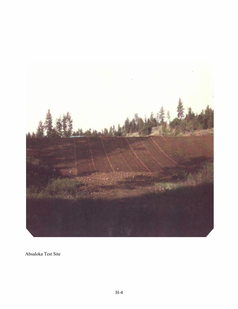
Absaloka Test Site
H-4