surface mount tech
DESCRIPTION
ppt on smtTRANSCRIPT

Surface Mount Technology
INTRODUCTION
Compact size of electronic equipment is due to surface mount
technology. Surface mount technology allow packaging of electronic components so
that the overall assembly is compact.
In SMT both components and conductive tracer (i.e. connections) are
installed on the same side of substrate or surface. Substrate can be ceramic, paper
plastic, rigid and flexible PCB’s.
Govt. Poly. Washim 1

Surface Mount Technology
SURFACE MOUNT COMPONENTS
Many but not all through whole components have a surface mountable
counter part. Due to some physical limitations so conventional components cannot
be manufactured as SMC (Surface Mount Components).
e.g.
High capacity capacitor and power transformers, still most circuit can
be assembled, using SMT, even though some conventional through hole components
are required.
It is important for SMT surface designer and service technician to
know the general physical configuration and operating parameters of various SMC’s.
All SMC’s in familiar are available separately SMC’s used for
automatic assemblies are supplied in rills of paper or in magazine.
DETAILS ABOUT SOME (SMC’S)
1. Chip resister :
These are most widely produced of all SMC’s. They are originally
developed for used in hybrid micro circuit. The chip registers are leadless registers.
Constructionally deice is similar to thick film resister.
The typical size of resisters are 1.6 3.2 mm., 1.4 2 mm, 2.6 3.3
mm. The resistance range of most chip resistor is 10 to 2.2 M some companies
manufacture up to the value of 10 M or higher than this.
Govt. Poly. Washim 2

Surface Mount Technology
2. Chip Capacitor :
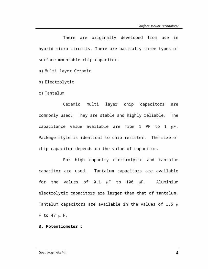
There are originally developed from use in hybrid micro circuits.
There are basically three types of surface mountable chip capacitor.
a) Multi layer Ceramic
b) Electrolytic
c) Tantalum
Ceramic multi layer chip capacitors are commonly used. They are
stable and highly reliable. The capacitance value available are from 1 PF to 1 F.
Package style is identical to chip resister. The size of chip capacitor depends on the
value of capacitor.
For high capacity electrolytic and tantalum capacitor are used.
Tantalum capacitors are available for the values of 0.1 F to 100 F. Aluminium
electrolytic capacitors are larger than that of tantalum. Tantalum capacitors are
available in the values of 1.5 F to 47 F.
3. Potentiometer :
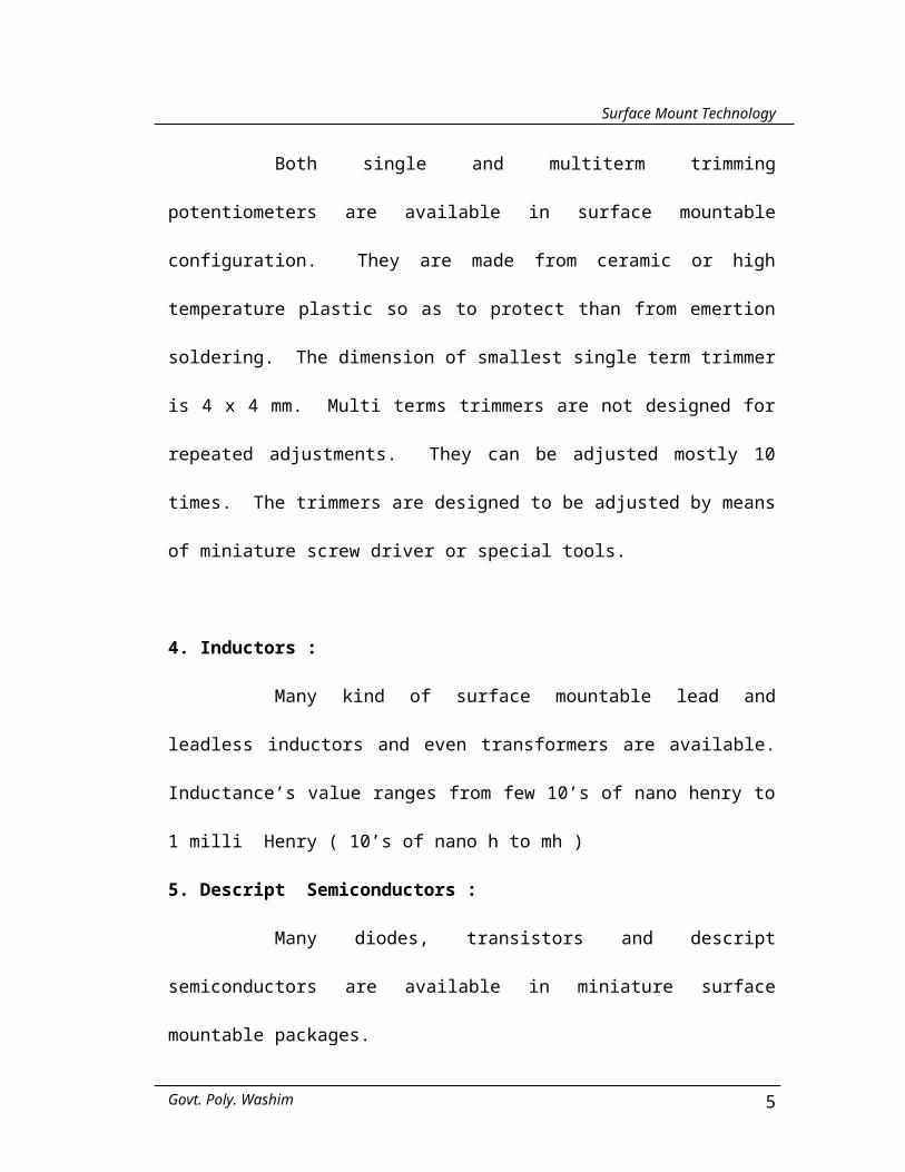
Both single and multiterm trimming potentiometers are available in
surface mountable configuration. They are made from ceramic or high temperature
plastic so as to protect than from emertion soldering. The dimension of smallest
single term trimmer is 4 x 4 mm. Multi terms trimmers are not designed for repeated
adjustments. They can be adjusted mostly 10 times. The trimmers are designed to
be adjusted by means of miniature screw driver or special tools.
Govt. Poly. Washim 3
Surface Mount Technology
4. Inductors :
Many kind of surface mountable lead and leadless inductors and even
transformers are available. Inductance’s value ranges from few 10’s of nano henry
to 1 milli Henry ( 10’s of nano h to mh )
5. Descript Semiconductors :
Many diodes, transistors and descript semiconductors are available in
miniature surface mountable packages.
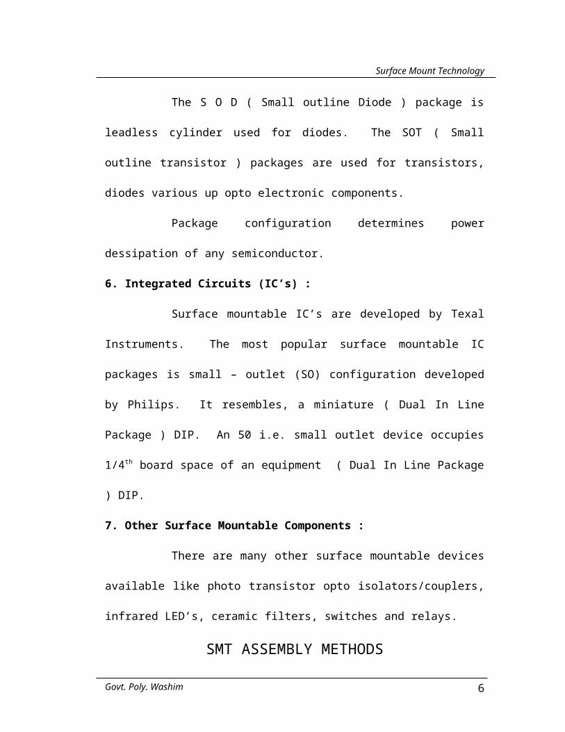
The S O D ( Small outline Diode ) package is leadless cylinder used
for diodes. The SOT ( Small outline transistor ) packages are used for transistors,
diodes various up opto electronic components.
Package configuration determines power dessipation of any
semiconductor.
6. Integrated Circuits (IC’s) :
Surface mountable IC’s are developed by Texal Instruments. The
most popular surface mountable IC packages is small – outlet (SO) configuration
developed by Philips. It resembles, a miniature ( Dual In Line Package ) DIP. An 50
i.e. small outlet device occupies 1/4th board space of an equipment ( Dual In Line
Package ) DIP.
7. Other Surface Mountable Components :
There are many other surface mountable devices available like photo
transistor opto isolators/couplers, infrared LED’s, ceramic filters, switches and
relays.
Govt. Poly. Washim 4
Surface Mount Technology
SMT ASSEMBLY METHODS
Surface mountable components like conventional through hole
components can be placed an a board or soldier in place either by hand or by
machine.
Hand assembly is used by home experimental and electronic
companies for the production of prototype SMT circuit boards.
AUTOMATIC SMT ASSEMBLY
Automatic placement equipment can select the position on circuit
board from 1000 to 5 lakhs components per hour. There are three other categories of
automatic SMC placements equipment (Mass placement).
CONDUCTING BONDING
Soldering is a cheap method for bonding SMCs and socket terminals
to circuit board pads. Conductive adhesive also used, both methods are important.
Govt. Poly. Washim 5
Surface Mount Technology
TYPES OF SOLDERING
There are various methods of soldering
1) Hand soldering.
2) Wave soldering.
3) Reflow soldering.
In hand soldering the soldering paste is applied to the board and the
SMCs are placed on it by hand, so it is called as hand soldering.
Reflow soldering is most important conductive bonding method for
SMC’s. The simplest form of reflow soldering occurs when tinned terminals and
thickly tinned pad is heated by soldering iron or other means. Until the two tinned
layers melt and merged together.
CONDUCTIVE ADHESIVE BONDING :
Conductive adhesives are used to bond the terminals of components to
the conductive traces. They are relatively easy to use and they eliminate thermal
shock of soldering. Numbers of families of adhesive are available, all of them
contain conductive powder in one or two part base. The most common conductive
powder in order of increasing resistance includes gold, silver, copper, nickel, carbon
and graphite. Adhesive base includes urathene, polyster and one or two part epoxies.
Govt. Poly. Washim 6

Surface Mount Technology
Conductive adhesives can be applied by hand using squeezable
dispenser, just like tooth paste and automatically metered gringe or a piece of wire.
They can also be applied by screening.
Thermoplastic conductive adhesives can be rework using heat from
ordinary soldering iron or hot air gun. The SMC’s can be removed after adhesive
becomes soften. A new SMCs can be bonded to the same location by reheating the
adhesive.
The major draw back of conductive adhesive is cost, self life, remains
for 6 to 12 month and hazardous vapour.
Govt. Poly. Washim 7

Surface Mount Technology
ADVANTAGES OF SMT
There are various advantages of SMT.
1. Reduce Circuit Board Size : The compact size of SMC’s considerably reduces
area of circuit board.
2. Light in weight : SMC’s are lighter than their through hole counter port. e.g.
8 – pin DIP, LM 308 M opamp weighs 600 mg. The so package vargen of same
IC Weighs 60 gm.
3. The low weight of SMC’s and smaller circuit board together gives 5 to 1 weight
advantages over conventional board. Also SMT boards are thin therefore they
gives 8:1 volume advantage over conventional boards.
4. Double – Sided Circuit Board : SMT can also used double sided board with an
advantage that components can be placed on the both sides.
5. Subminiature Circuits : SMT circuits are nearly as tiny as hybrid integrated
circuits.
6. Automated assembly : SMCs are much more compacted with automatic
assembly equipment. The time consuming in drilling holes in circuit board is
climinated. SMC’s have no wire leads to cut, bend and insert. Therefore SMT
boards can be automatically assemble quickly than conventional boards.
7. Lower Cost : The SMC’s cost is generally more, till SMT can reduce over all
board cost for variety of reasons. e.g. saving of 40% cost results from elimination
of drilling hole equipment.
8. Other Advantages : Some advantages of SMT are less obvious than above.
i) Compact size of SMT so it is used in mobile.
Govt. Poly. Washim 8

Surface Mount Technology
DISADVANTAGES OF SMT
1. SMC Standardisation : The same SMC from two different manufacturers may
have different dimensions, which may create a problem. Hence standardisation
is necessary. Till today no standardisation is made.
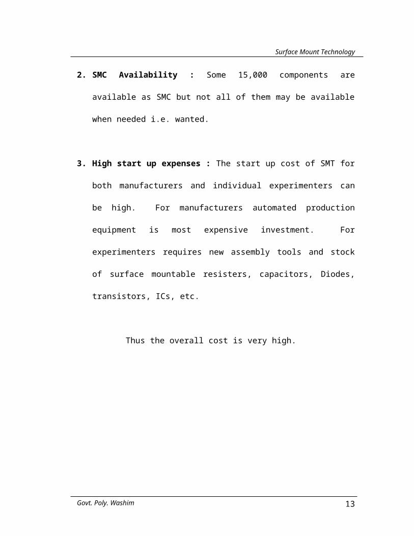
2. SMC Availability : Some 15,000 components are available as SMC but not all
of them may be available when needed i.e. wanted.
3. High start up expenses : The start up cost of SMT for both manufacturers and
individual experimenters can be high. For manufacturers automated production
equipment is most expensive investment. For experimenters requires new
assembly tools and stock of surface mountable resisters, capacitors, Diodes,
transistors, ICs, etc.
Thus the overall cost is very high.
Govt. Poly. Washim 9

Surface Mount Technology
INSPECTION, TESTING AND REPAIRING
Due to small size of components SMT board requires very careful
inspection particularly for solder ball, improperly soldered joints and missed soldver
connections, etc.
Some components are specially difficult to inspect like quad PLCC’s
(Plastic Loaded Chip Carrier) i.e. IC having J – profile pins along each four sides and
it has more than 28 pins.
Complete SMT board can be tested by hand or automatic testing
equipment. Whether testing is done by hand or automatically the test probes should
be touch to SMC’s solder pad or their conductive traces. The test probes should not
be touch to terminals of SMC’s properly designed SMT boards have test point
location. Replacing defective SMC’s required more patience and care because they
are very small and are placed very closed to other components.
While desoldering care must be taken to prevent over heating of board
and nearby SMC’s. When solder melts SMC’s should be twisted before it is lifted
from the board to broke the solder surface tension otherwise solder pad may comes
out of the mode.
Installing new SMC is not difficult just place the SMC and heat its
terminal for best result and old solder should be removed using desoldering tools.
Thus the repairing of SMT circuit is difficult, so we can install new
circuit instead repairing faulty circuit.
Govt. Poly. Washim 10

Surface Mount Technology
CONCLUSION
From the above discussion I conclude that SMT is more advantages
than the conventional circuit board. Because it reduces the size of circuit board, cost,
weight etc.
Due to above advantages SMT circuit can be mount on the coin or on
the postal stamp. Also the circuit can be mounted on both sides of the circuit board.
So now a days it is used in mobile, calculator or the circuit where small space circuit
is required.
Govt. Poly. Washim 11

Surface Mount Technology
REFERENCE
1. W.W.W. Smta. Org
2. Electronic Packaging and Integrating Hand book.
- By Harper
3. Electronics for you – July 1995
4. Electronics for you – Oct. 1999
Govt. Poly. Washim 12
Surface Mount Technology
Internal ElectrodeSecondary Electrode
Protective GlassOvercoat
External Electrode (Solder)
Ceramic Substrate Register
INSIDE A LEADLESS CHIP REGISTOR
External Electrode (Solder)
Ceramic Substrate
Interleaved Electrodes Dielectric
INSIDE A CERAMIC CHIP CAPACITOR
Govt. Poly. Washim 13
Surface Mount Technology
Gull Wing J - Lead
SOP PLCC
PCB
Discrete Component
MSP
Butt Lead
VARIOUS SHAPES OF THE PINS
DIP Discrete Component
PCB
Through Hole SolderedDISCRETE COMPONENTS SOLDERED ON OPPOSITE SIDE OF
COMPONENT SIDE
SOP PLCC
PCB Discrete Component
MSP
SURFACE MOUNT COMPONENT SOLDERED ON FOOT PRINTS OF PCB
Govt. Poly. Washim 14
Surface Mount Technology
REFLOW SOLDERING PROCESS PLAN
Govt. Poly. Washim 15
Solderability Testing
Component Pretin
Component Preform (Leaded)
Component Assembly
Stencil Solder Paste
Board Surface Preparation
Board Prebake
Solder Paste Cure
Reflow Deflux Assembled Board
Component Coat
COMPONENTS SUBSTRATES
SOLDER PASTE SCREENDEVICE
PLACEMENTBAKEREFLOW
SOLDERINGCLEANINGINSPECTION & REWORK
ELECTRICAL TEST INVERT BOARD

Surface Mount Technology
FLOW CHART FOR SMT
Govt. Poly. Washim 16