surface rev. dec2000 standardallaboutmetallurgy.com/wp/wp-content/uploads/2016/12/saej431v002.pdfsae...
TRANSCRIPT

SAE Technical Standards Board Rules provide that: “This report is published by SAE to advance the state of technical and engineering sciences. The use of this report is entirelyvoluntary, and its applicability and suitability for any particular use, including any patent infringement arising therefrom, is the sole responsibility of the user.”
SAE reviews each technical report at least every five years at which time it may be reaffirmed, revised, or cancelled. SAE invites your written comments and suggestions.
TO PLACE A DOCUMENT ORDER: +01 724-776-4970 FAX: +01 724-776-0790SAE WEB ADDRESS http://www.sae.org
Copyright 2000 Society of Automotive Engineers, Inc.All rights reserved. Printed in U.S.A.
SURFACEVEHICLE
400 Commonwealth Drive, Warrendale, PA 15096-0001STANDARD
Submitted for recognition as an American National Standard
J431REV.
DEC2000
Issued 1935-01Revised 2000-12
Superseding J431 AUG1996
(R) Automotive Gray Iron Castings
1. Scope—This SAE Standard covers the hardness, tensile strength, and microstructure and specialrequirements of gray iron sand molded castings used in the automotive and allied industries. Specificrequirements are provided for hardness of castings. Test bar tensile strength/Brinell hardness (t/h) ratiorequirements are provided to establish a consistent tensile strength-hardness relationship for each grade tofacilitate prediction and control of tensile strength in castings. Provision is made for specification of specialadditional requirements of gray iron automotive castings where needed for particular applications and serviceconditions.
NOTE—This document was revised in 1993 to provide grade specific t/h control. In 1999 the document wasrevised to make SI metric units primary. To better align the grading system with long establishedproduction methods and grades produced, the previous system of grading by fixed combinations oftensile strength and hardness was changed in 1999 to a system of grading by variable combinations oftest bar t/h ratio and casting hardness grades. The number of hardness grades was increased relativeto the number of previously available ranges to facilitate centering of casting mean hardness in thespecification range so that dependence of cost optimization on controlling near the low or high sides ofspecification ranges is minimized.
2. References
2.1 Applicable Publications—The following publications form a part of this specification to the extent specifiedherein. Unless otherwise indicated, the latest issue of SAE publications shall apply.
2.1.1 SAE PUBLICATION—Available from SAE, 400 Commonwealth Drive, Warrendale, PA 15096-0001.
SAE J417—Hardness Tests and Hardness Number Conversions
2.1.2 ASTM PUBLICATIONS—Available from ASTM, 100 Barr Harbor Drive, West Conshohocken, PA 19428-2959.
ASTM A 48—Specification for Gray Iron CastingsASTM A 247—Recommended Practice for Evaluating the Microstructure of Graphite in Iron CastingsASTM A 438—Transverse Testing of Gray Cast IronASTM E 10—Test for Brinell Hardness of Metallic MaterialsASTM E 562—Determining Volume Fraction by Systematic Manual Point Count

SAE J431 Revised DEC2000
-2-
2.2 Related Publications—The following publications are provided for information purposes only and are not arequired part of this document. Additional information concerning gray iron castings, their properties, and usecan be obtained from:
1. Metals Handbook, Vol. 1, 10th Edition, ASM International, Materials Park, OH2. Cast Metals Handbook, American Foundrymen's Society, Des Plaines, IL3. 1981 Iron Castings Handbook, Iron Castings Society, Inc., Cleveland, OH4. H.D. Angus, “Physical and Engineering Properties of Cast Iron,” British Cast Iron Research
Association, Birmingham, England, 2nd Edition, 19765. “Gray, Ductile, and Malleable Iron Castings Current Capabilities,” STP-455, American Society for
Testing and Materials, 100 Barr Harbor Drive, West Conshohocken, PA 19428-29596. G.N.J. Gilbert, “Engineering Data on Grey Cast Iron,” BCIRA (1977), Alvechurch, Birmingham,
England7. “Tables for Normal Tolerance Limits, Sampling Plans and Screening,” R.E. Odeh and D.B. Owen,
Marcel Dekker, Inc., New York and Basel, 19808. “Fatigue Properties of Gray Cast Iron,” L.E. Tucker and D.R. Olberts, SAE Paper 690471
3. Grade definition and Designation.
3.1 Iron Grade—Gray iron grades, defined by their minimum test bar t/h ratio, are designated by the letter Gfollowed by a number equaling the defining minimum test bar t/h ratio multiplied by 100. The units used for thispurpose are MPa for both tensile strength and hardness. The t/h ratio is dimensionless.
EXAMPLE—G10 designates a gray iron having minimum test bar t/h = 0.100.
3.2 Hardness Grade—Hardness grades, defined by minimum hardness exhibited in castings, are designated bythe letter H followed by a number equaling the minimum casting hardness divided by 100. The castinghardness unit used for this purpose is the MPa.
EXAMPLE—H18 designates minimum casting hardness of 1800 MPa.
3.3 Casting Grade—SAE gray iron casting grades are defined and designated by combining the iron grade andthe hardness grade designations.
EXAMPLE—G10H18 designates iron in castings with minimum test bar t/h of 0.100 MPa/MPa and minimumcasting hardness of 1800 MPa.
3.4 Special Requirements—Special requirements, defined for special applications, are designated by alowercase suffix letter placed at the end of the casting grade designation.
EXAMPLE—11H20b designates iron meeting special requirements of special service brakedrums.
3.5 Equivalency and Conversion—Equivalency information for engineering purposes, between this and otherstandards, is provided in A.4.1, A.4.6, and A.4.7. Grades of this document can have multiple equivalents withgrades of previous SAE and most other standards as exemplified by grades G3000 and G4000. Determinationof current grade equivalent for castings established in production under previous SAE or other documents,shall be by the producer, in accordance with 5.5.3, based on historical or current test data from the establishedprocess, and reported to and approved by the purchaser. When the producer does not have access to theapplicable historical data, grade determination shall be based on samples provided by producer and approvedby purchaser.

SAE J431 Revised DEC2000
-3-
4. Grades
4.1 Iron Grades—Iron grades and their t/h lower limit requirements are shown in Table 1.
4.2 Hardness Grades—Hardness grades and their required lower hardness limits are shown in Table 2.
4.3 Special Requirements—Special additional requirements for particular applications and service conditionsand their lower case letter designators are shown in Table 3. Special additional requirements shall not changetest bar t/h ratio or casting hardness requirements.
TABLE 1—IRON GRADES
Grade
Test Bar t/hRatio Lower Limit(1)
MPa/MPa(2)
1. Statistically defined2. Both tensile and hardness in MPA units
Test Bar t/hRatio Lower Limit(1)
psi/HB(3)(4)
3. For reference only. The MPa/MPa SI metric values are primary. See Section 1.
4. Units of HB are kgf per mm2.
G7 0.070 100
G9 0.090 128
G10 0.100 142
G11 0.110 156
G12 0.120 171
G13 0.130 185
TABLE 2—HARDNESS GRADES
Grade
Casting HardnessLower Limit(1)
MPa(2)
1. Statistically Defined.2. Hardness in MPa = HB multiplied by 9.80665.
Casting HardnessLower Limit(1)
HB(3)
3. Units of HB are kgf per mm2.
H10 1000 102
H11 1100 112
H12 1200 122
H13 1300 133
H14 1400 143
H15 1500 153
H16 1600 163
H17 1700 173
H18 1800 184
H19 1900 194
H20 2000 204
H21 2100 214
H22 2200 224
H23 2300 235
H24 2400 245
SAE J431 Revised DEC2000
-4-
4.4 Casting Grades—Combination of iron grade, hardness grade, and special requirement designation, if any,defines casting grade. A partial list of casting grades in common production and use, identified as referencegrades and considered standard, is given in Table 4 with current and previous SAE designations. Othercombinations of iron grade and hardness grade which are established in production and use or become so inthe course of application development, or in accordance with 3.5 and 5.5.3, are also considered standard.
NOTE—For castings successfully established in production and use under previous designations, the currentSAE casting grade shall be determined by the producer and approved by the purchaser (see 3.5).
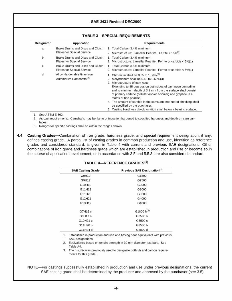
TABLE 3—SPECIAL REQUIREMENTS
Designator Application Requirements
a Brake Drums and Discs and Clutch Plates for Special Service
1. Total Carbon 3.4% minimum.
2. Microstructure: Lamellar Pearlite. Ferrite < 15%(1)
1. See ASTM E 562.
b Brake Drums and Discs and Clutch Plates for Special Service
1. Total Carbon 3.4% minimum.2. Microstructure: Lamellar Pearlite. Ferrite or carbide < 5%(1)
c Brake Drums and Discs and Clutch Plates for Special Service
1. Total Carbon 3.5% minimum.2. Microstructure: Lamellar Pearlite. Ferrite or carbide < 5%(1)
d Alloy Hardenable Gray Iron
Automotive Camshafts(2)
2. As-cast requirements. Camshafts may be flame or induction hardened to specified hardness and depth on cam sur-faces.
1. Chromium shall be 0.85 to 1.50%(3)
2. Molybdenum shall be 0.40 to 0.60%(3)3. Microstructure of cam nose:
Extending to 45 degrees on both sides of cam nose centerlineand to minimum depth of 3.2 mm from the surface shall consistof primary carbide (cellular and/or acicular) and graphite in amatrix of fine pearlite.
4. The amount of carbide in the cams and method of checking shallbe specified by the purchaser.
5. Casting Hardness check location shall be on a bearing surface.
3. Ranges for specific castings shall be within the ranges shown.
TABLE 4—REFERENCE GRADES(1)
1. Established in production and use and having near equivalents with previous SAE designations.
SAE Casting Grade Previous SAE Designation(2)
2. Equivalency based on tensile strength in 30 mm diameter test bars. See Table A4.
G9H12 G1800
G9H17 G2500
G10H18 G3000
G11H18 G3000
G11H20 G3500
G12H21 G4000
G13H19 G4000
G7H16 c G1800 h(3)
3. The h suffix was previously used to designate both t/h and carbon require-ments for this grade.
G9H17 a G2500 a
G10H21 c G3500 c
G11H20 b G3500 b
G11H24 d G4000 d
SAE J431 Revised DEC2000
-5-
5. Tensile Strength to Hardness Ratio, Hardness, and Casting Tensile Strength
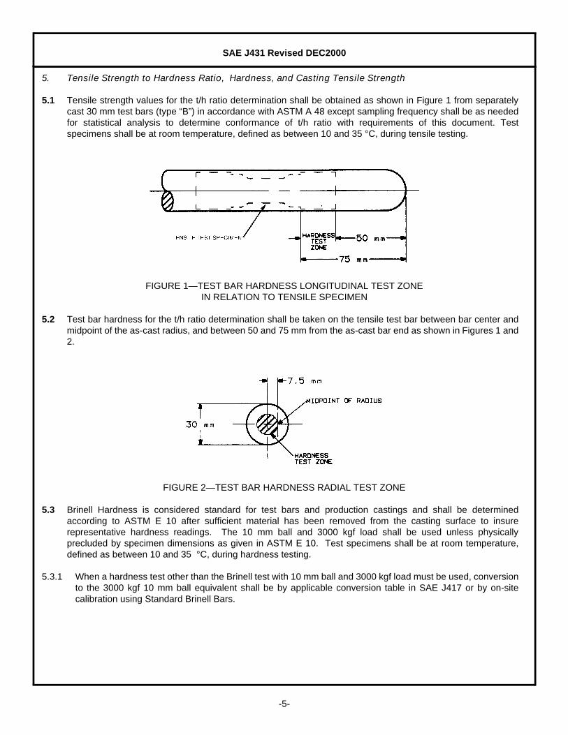
5.1 Tensile strength values for the t/h ratio determination shall be obtained as shown in Figure 1 from separatelycast 30 mm test bars (type “B”) in accordance with ASTM A 48 except sampling frequency shall be as neededfor statistical analysis to determine conformance of t/h ratio with requirements of this document. Testspecimens shall be at room temperature, defined as between 10 and 35 °C, during tensile testing.
FIGURE 1—TEST BAR HARDNESS LONGITUDINAL TEST ZONEIN RELATION TO TENSILE SPECIMEN
5.2 Test bar hardness for the t/h ratio determination shall be taken on the tensile test bar between bar center andmidpoint of the as-cast radius, and between 50 and 75 mm from the as-cast bar end as shown in Figures 1 and2.
FIGURE 2—TEST BAR HARDNESS RADIAL TEST ZONE
5.3 Brinell Hardness is considered standard for test bars and production castings and shall be determinedaccording to ASTM E 10 after sufficient material has been removed from the casting surface to insurerepresentative hardness readings. The 10 mm ball and 3000 kgf load shall be used unless physicallyprecluded by specimen dimensions as given in ASTM E 10. Test specimens shall be at room temperature,defined as between 10 and 35 °C, during hardness testing.
5.3.1 When a hardness test other than the Brinell test with 10 mm ball and 3000 kgf load must be used, conversionto the 3000 kgf 10 mm ball equivalent shall be by applicable conversion table in SAE J417 or by on-sitecalibration using Standard Brinell Bars.

SAE J431 Revised DEC2000
-6-
5.4 A non-destructive casting hardness test location on the casting for monitoring conformance to grade limits shallbe established by agreement between purchaser and producer or determined by producer. It should be readilyaccessible for convenience in performing the test to ensure adequate quantity, consistency, and accuracy ofaccumulated data for statistical validity in service of general variance control. Targeting of hardnessmeasurement at service function related locations shall not be considered a requirement unless specified inaccordance with 5.4.1.
5.4.1 In special cases, casting hardness at particular casting locations considered critical by the designer butdifficult to access or requiring casting destruction may be specified by the purchaser with produceragreement. In such cases, hardness grade conformance may be established directly by hardness readingsso obtained or indirectly by hardness readings at an accessible location using an agreed method ofcorrelation.
5.5 The foundry shall exercise the necessary controls and inspection techniques to ensure compliance with thespecified hardness and t/h ratio minimums. When samples exhibit normal variance patterns, conformancewith grade requirements for t/h and casting hardness shall be determined by long term analysis of productionsamples using Normal Curve statistical methods. For sample sizes less than 30, the lower limit shall be takenas 3 standard deviations below the mean. For sample sizes larger than 30, the lower limits for t/h and castinghardness control may be optionally taken as the lower 3 standard deviation limit or the lower 99% populationlimit of the one-sided normal distribution at 95% confidence calculated by the confidence interval method (seeA.1.5).
5.5.1 Test bar samples to confirm test bar t/h ratio conformance shall be random samples. Frequency of samplingmay be specified by purchaser or determined by producer. Minimum frequency per grade shall be 1 per 8 hshift. Sample period may be any time interval or accumulation of time intervals in which the targeted meant/h of producer’s process control specifications is unchanged.
5.5.2 Casting samples to confirm casting hardness conformance shall be random samples. Frequency ofsampling may be specified by purchaser or determined by producer. Minimum frequency shall be the leastof 5 per 8 h shift or 100% of production. Sample period may be any time interval or accumulation of timeintervals during which the targeted mean casting hardness of producer’s process control specifications isunchanged.
5.5.3 Parts successfully established in production and use under previous SAE or other Standards shall bereclassified under this document, without change in mean test bar t/h or mean casting hardness, byappropriate selection of iron grade from Table 1, casting hardness grade from Table 2, and casting hardnessrange under 5.6.
5.5.4 Casting t/h data obtained by casting hardness tests as described in 5.4 or 5.4.1 and casting tensile tests asdescribed in 5.7, shall be considered informational only and shall not be used for grade conformanceassessment.
5.5.5 When casting hardness and/or test bar t/h variance patterns have too much skewness or otherwise do notsupport Normal Curve methods of analysis, an alternate method shall be established by agreement ofpurchaser and producer which achieves population limit control equivalent to that described in 5.5.
5.6 Casting hardness range may be specified by the purchaser to provide a non-statistical upper limit formachinability control. The standard range shall be 600 MPa or 60 HB, taken above the required grademinimum, and this shall be the assumed range when not specified. Purchasers shall not specify narrowerranges than this without prior agreement of the producer. Producers shall not exceed this range without prioragreement of the purchaser.

SAE J431 Revised DEC2000
-7-
5.7 A minimum value for tensile strength determined by destructive testing at specified locations in castings maybe specified as an additional, part number specific, conformance requirement by agreement betweenpurchaser and producer on the applicable lower limit and statistical definition, sampling rate,and any specialtesting methods required. The agreed minimum shall be obtained with a standard grade as defined in thisdocument. Information for estimating and experimentally determining the tensile minimum which can beexpected for a given grade at specific locations in castings for purposes of design and development is given inSection A.4.
5.8 A statistical lower limit for tensile/hardness ratio determined by destructive testing at specified locations incastings may be specified as an additional, part number specific, conformance requirement by agreementbetween purchaser and producer on the applicable lower limit and statistical definition, sampling rate, and anyspecial testing methods required. The agreed minimum shall be obtained with a standard grade as defined inthis document. Information for estimating and experimentally determining the tensile/hardness ratio minimumwhich can be expected for a given grade at specific locations in castings for purposes of design anddevelopment is given in Section A.4.
6. Heat Treatment
6.1 Castings of hardness grades H10 through H17 may be annealed to meet hardness requirements. Castings ofgrades H21 through H24 may be quenched and tempered to meet hardness requirements.
6.2 Appropriate heat treatment for removal of residual stresses, or to improve machinability or wear resistance,may be specified. Heat treated castings must meet hardness requirements of the grade.
7. Microstructure
7.1 Unless otherwise specified, gray iron covered by this document shall be substantially free of primary cementiteand/or massive steadite and shall consist of flake graphite in a matrix of ferrite or pearlite or mixtures thereof.
7.2 Unless otherwise specified, the graphite structure shall be primarily type A in accordance with ASTM A 247.
8. Castings for Special Applications with Controlled Composition and Microstructure
8.1 Heavy-Duty Brake Drums and Clutch Plates
8.1.1 These castings are considered as special cases and are covered in Tables 3 and 4.
8.2 Alloy Iron Automotive Camshafts
8.2.1 These castings are considered as special cases and are covered in Table 3 and 4.
9. General Requirements
9.1 Castings furnished to this document shall be representative of good foundry practice and shall conform todimensions and tolerances specified on the casting drawing.
9.2 Approval by purchaser of location on the casting and method to be used is required for any casting repair.
9.3 Additional casting requirements such as vendor identification, other casting information, and special testingmay be agreed upon by purchaser and supplier. These should appear as product specifications on the castingor part drawing.
SAE J431 Revised DEC2000
-8-
10. Notes
10.1 Marginal Indicia—The change bar (l) located in the left margin is for the convenience of the user in locatingareas where technical revisions have been made to the previous issue of the report. An (R) symbol to the leftof the document title indicates a complete revision of the report.
PREPARED BY THE SAE IRON AND STEEL TECHNICAL COMMITTEE DIVISION 9—AUTOMOTIVE IRON AND STEEL CASTINGS OF THE
SAE IRON AND STEEL TECHNICAL EXECUTIVE COMMITTEE

SAE J431 Revised DEC2000
-9-
APPENDIX A
NOTE—Information in the Appendix is for reference only and does not constitute requirements.
A.1 Definition and Control of Gray Iron
A.1.1 Gray iron is a cast iron in which the graphite is present in flake form instead of nodules or spheroids as inmalleable or ductile iron. Because its graphite has this flake structure, gray iron exhibits much greatersensitivity of mechanical properties to carbon content than malleable or ductile. As in malleable and ductile,the metallic matrix in which the graphite of gray iron resides is normally either eutectoid or hypo-eutectoidsilicon steel with a working range of hardness of about 150 to 600 HB (1.5 to 6 GPa). In special cases, thematrix may be martensitic or hyper-eutectoidal with working hardness up to about 800 HB (8 GPa)
A.1.2 Gray iron naturally divides into a family or series of grades having different tensile strength to hardness (t/h)ratios uniformly regulated by eutectic graphite content up to the eutectic composition as shown in Figure A1with carbon equivalent(CE) as the graphite parameter. Decline in t/h ratio continues as CE increases abovethe eutectic, but at a much smaller and less predictable rate. Constant t/h lines of this figure are essentiallylines of constant graphite effect on mechanical properties. Properties sensitive to both graphite and matrix,such as bulk tensile strength and bulk hardness, vary in constant proportionality to each other and to theirmatrix counterparts—matrix tensile strength and matrix hardness—along constant t/h lines. Elastic modulusand damping capacity vary mainly only with graphite and are therefore highly constant along the constant t/hlines. Since these lines are also lines of constant eutectic graphite and CE, the most important castabilityparameters, they are logical grade lines for foundry control as well as for mechanical property control.
FIGURE A1—CHARACTERISTIC t/h RATIOS OF GRAY IRONS
A.1.3 Specification control of gray iron, since it is a composite material, requires joint classification by at least twoproperty parameters of which one should be mainly graphite microstructure related and the other mainly afunction of the matrix microstructure. Limited effectiveness of control by a single bulk property is illustrated inFigures A2 and A3. Figure A2 exemplifies grading by tensile strength alone—any given grade so defined isseen to traverse a wide range of possible hardness minimums. Likewise, in Figure A3, hardness is used as asingle defining property and a wide range of possibilities exists for the tensile minimum. In both cases, t/h ratioand therefore, elastic modulus, damping capacity and castability are undefined. Figure A4 illustrates improvedcontrol obtainable by jointly specifying two property parameters. In this example, t/h ratio and hardness are thejoint control parameters. A tensile minimum is now defined and, in general, all properties including castabilityare effectively controlled.

SAE J431 Revised DEC2000
-10-
FIGURE A2—GRADING BY TENSILE
FIGURE A3—GRADING BY HARDNESS
FIGURE A4—GRADING BY t/h RATIO AND HARDNESS
SAE J431 Revised DEC2000
-11-
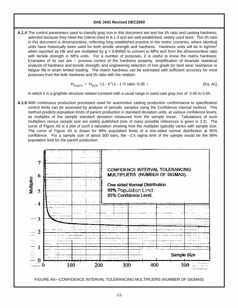
A.1.4 The control parameters used to classify gray iron in this document are test bar t/h ratio and casting hardness,selected because they meet the criteria cited in A.1.3 and are well established, widely used tests. The t/h ratioin this document is dimensionless, reflecting long established practice in the metric countries, where identicalunits have historically been used for both tensile strength and hardness. Hardness units will be in kg/mm2
when reported as HB and are multiplied by g = 9.80665 to convert to MPa and form the dimensionless ratiowith tensile strength in MPa units. For a number of purposes, it is useful to know the matrix hardness.Examples of its use are -- process control of the hardness property, simplification of bivariate statisticalanalysis of hardness and tensile strength, and engineering selection of iron grade for best wear resistance orfatigue life in strain limited loading. The matrix hardness can be estimated with sufficient accuracy for mostpurposes from the bulk hardness and t/h ratio with the relation:
(Eq. A1)
in which k is a graphite structure related constant with a usual range in sand cast gray iron of 0.60 to 0.65.
A.1.5 With continuous production processes used for automotive casting production conformance to specificationcontrol limits can be assessed by analysis of periodic samples using the Confidence Interval method. Thismethod predicts population limits of parent production in standard deviation units, at various confidence levels,as multiples of the sample standard deviation measured from the sample mean. Tabulations of suchmultipliers versus sample size are widely published (one of many possible references is given in 2.2). Thecurve of Figure A5 is a plot of such a tabulation showing how the multiplier typically varies with sample size.The curve of Figure A5 is drawn for 99% population limits of a one-sided normal distribution at 95%confidence. For a sample size of about 300 bars, the –2.5 sigma limit of the sample would be the 99%population limit for the parent production.
FIGURE A5—CONFIDENCE INTERVAL TOLERANCING MULTIPLIERS (NUMBER OF SIGMAS)
Hmatrix Hbulk 1 k∗ 1 t h ratio 0.35⁄⁄–( )–[ ]⁄=

SAE J431 Revised DEC2000
-12-
A.2 Chemical Composition
A.2.1 Typical base composition ranges generally employed for the iron grades are shown in Table A1. The basecomposition does not include alloys such as Cu, Cr, Mo, Ni, or others which may be added for hardness or t/hcontrol, or to meet mandatory composition limits of special irons given in Table 3 of the main body of thisdocument.
A.2.2 Typical base composition ranges may vary for specific grades depending on casting section size ormetallurgical factors such as trace element content, or to satisfy mandatory composition requirements ofspecial irons as given in Table 3.
A.2.3 Typical composition ranges including typical alloy content for camshaft iron, grade G11H24d, are shown inTable A2.
A.3 Microstructure
A.3.1 The as-cast microstructure of gray iron covered by this document consists of a mixture of flake graphite in amatrix consisting of ferrite, ferrite and pearlite, or pearlite, as described in Table A3. The quantity of flakegraphite and size of the flakes vary with iron grade. The amount and fineness of pearlite vary with thehardness grade. The pearlite is usually lamellar but may be partially spheroidal in slowly cooled sections orwhere heat treatment has been applied.
TABLE A1—TYPICAL BASE COMPOSITIONS
IronGrade
PreviousDesignation Carbon Silicon Manganese
SulfurMax.
Phosphorusmax
C. E.(1)
(Approx.)
1. C. E. (Carbon Equivalent) = %C + (1/3) %Si.
G7 G1800h 3.50 - 3.70 2.30 - 2.80 0.60 - 0.90 0.14 0.25 4.35 - 4.55
G9 G2500 3.40 - 3.65 2.10 - 2.50 0.60 - 0.90 0.12 0.25 4.15 - 4.40
G10 G3000 3.35 - 3.60 1.90 - 2.30 0.60 - 0.90 0.12 0.20 4.05 - 4.30
G11 G3000 3.30 - 3.55 1.90 - 2.20 0.60 - 0.90 0.12 0.10 4.00 - 4.25
G12 G3500 3.25 - 3.50 1.90 - 2.20 0.60 - 0.90 0.12 0.10 3.95 - 4.20
G13 G4000 3.15 - 3.40 1.80 - 2.10 0.70 - 1.00 0.12 0.08 3.80 - 4.05
TABLE A2—TYPICAL CHEMICAL COMPOSITION OF ALLOY GRAY IRONAUTOMOTIVE CAMSHAFTS, GRADE G11H24d (PREVIOUS 4000d)
Constituent Wt %
Total Carbon 3.10 to 3.60
Silicon 1.95 to 2.40
Manganese 0.60 to 0.90
Phosphorus 0.10 max
Sulfur 0.15 max
Chromium 0.85 to 1.50
Molybdenum 0.40 to 0.60
Nickel 0.20 to 0.45
Copper Residual

SAE J431 Revised DEC2000
-13-
A.3.2 The size and distribution of graphite flakes in gray iron depend upon chemistry, liquid metal treatment(inoculation), and cooling rate during solidification. The primary, but not sole, chemical determinant is carbonequivalent, defined as C+Si/3.
A.3.2.1 Alloying elements used for pearlite hardness control have small but non-negligible effects on graphite size.Since some elements operate as coarsening and others as refining agents, combinations can be used for aneutral effect.
A.3.2.2 When alloying elements are used to produce a mixed structure of primary carbide and graphite, as in thecams of alloy hardenable gray iron automotive camshafts, eutectic graphite is reduced and significant flakerefinement results.
A.3.2.3 The graphite microstructure of gray iron cannot be changed by heat treatment.
A.3.3 Hardness of the ferrite in the gray iron matrix is unaffected by cooling rate but is affected by alloy elements insolid solution, the most noticeable being silicon, which increases ferrite hardness about 35 HB for each 1% ofSilicon present. Heat treatment is required to decompose all pearlite and produce a fully ferritic structure.
A.3.4 The amount and hardness of pearlite depend jointly on cooling rate and alloy chemistry, which are balanced inthe foundry to control pearlite amount and hardness and, consequentially, casting hardness. Both the amountand hardness of pearlite can be altered by heat treatment.
A.3.5 In special cases such as alloy hardenable iron camshafts, alloy is also used to obtain controlled percentages ofcarbides, detracting from graphite, in cam and valve lifter surfaces where maximum contact stress occurs. Theas-cast matrix structure in these cases is pearlite; in the contact surfaces, the matrix is transformed totempered martensite by surface heat treatment.
A.3.6 Gray iron castings can be through-hardened by liquid quenching or selectively surface-hardened by eitherflame or induction methods.
TABLE A3—TYPICAL MICROSTRUCTURES OF REFERENCE GRADES
SAECastingGrade
PreviousDesignation
Microstructure
Graphite(1)
1. See ASTM A 247.
MicrostructureMatrix
G9H12 G1800 Type VII A & B Ferritic - Pearlitic
G9H17 G2500 Type VII A & B Pearlitic - Ferritic
G10H18 G3000 Type VII A Pearlitic
G11H18 G3000 Type VII A Pearlitic
G11H20 G3500 Type VII A Pearlitic
G12H21 G4000 Type VII A Pearlitic
G13H19 G4000 Type VII A Pearlitic
G7H16 c G1800 h Type VII A, B, & C size 1-3 Lamellar Pearlite
G9H17 a G2500 a Type VII A size 2-4 Lamellar Pearlite
G10H21 c G3500 c Type VII A size 3-5 Lamellar Pearlite
G11H20 b G3500 b Type VII A size 3-5 Lamellar Pearlite
G11H24 d G4000 d Type VII A & E size 4-7(1) Pearlitic - Carbidic(2)
2. In cam nose. As cast. matrix pearlite in cam may be transformed to tempered Martensite by subsequent Flame or induction hardening.
SAE J431 Revised DEC2000
-14-
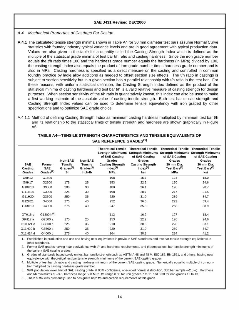
A.4 Mechanical Properties of Castings For Design
A.4.1 The calculated tensile strength minima shown in Table A4 for 30 mm diameter test bars assume Normal Curvestatistics with foundry industry typical variance levels and are in good agreement with typical production data.Values are also given in the table for a quantity called the Casting Strength Index which is defined as themultiple of the statistical grade minima of test bar t/h ratio and casting hardness. Since the iron grade numberequals the t/h ratio times 100 and the hardness grade number equals the hardness (in MPa) divided by 100,the casting strength index also equals the product of iron grade number times hardness grade number and isalso in MPa. Casting hardness is specified as a direct measure on the casting and controlled in commonfoundry practice by ladle alloy additions as needed to offset section size effects. The t/h ratio in castings issubject to section sensitivity but in a given section has a parallel relationship with t/h ratio in the test bar. Forthese reasons, with uniform statistical definition, the Casting Strength Index defined as the product of thestatistical minima of casting hardness and test bar t/h is a valid relative measure of casting strength for designpurposes. When section sensitivity of the t/h ratio is quantitatively known, this index can also be used to makea first working estimate of the absolute value of casting tensile strength. Both test bar tensile strength andCasting Strength Index values can be used to determine tensile equivalency with iron graded by otherspecifications and to optimize SAE grade choice.
A.4.1.1 Method of defining Casting Strength Index as minimum casting hardness multiplied by minimum test bar t/hand its relationship to the statistical limits of tensile strength and hardness are shown graphically in FigureA6.
TABLE A4—TENSILE STRENGTH CHARACTERISTICS AND TENSILE EQUIVALENTS OFSAE REFERENCE GRADES(1)
1. Established in production and use and having near equivalents in previous SAE standards and test bar tensile strength equivalents in other standards.
SAECastingGrades
FormerSAE
Grades(2)
2. Former SAE grades having near equivalence with t/h and hardness requirements, and theoretical test bar tensile strength minimums of the current SAE casting grades.
Non-SAETensile
Grades(3)
SI
3. Grades of standards based solely on test bar tensile strength such as ASTM A 48 and 48 M, ISO 185, EN 1561, and others, having near equivalence with theoretical test bar tensile strength minimums of the current SAE casting grades.
Non-SAETensile
Grades(3)
Inch-lb
Theoretical TensileStrength Minimums
of SAE Casting Grades
Casting StrengthIndex(4)
MPa
4. Multiple of test bar t/h ratio and casting hardness minimum of the current SAE casting grade. Numerically equal to multiple of iron num-ber multiplied by casting hardness grade number.
Theoretical TensileStrength Minimums
of SAE Casting Grades
Casting StrengthIndex(4)
ksi
Theoretical TensileStrength Minimums
of SAE Casting Grades
30 mm Dia.Test Bars(5)
MPa
5. 99% population lower limit of SAE casting grade at 95% confidence, one-sided normal distribution, 300 bar sample (–2.5 σ). Hardness and t/h minimums at –3 σ, hardness range 500 MPa, t/h range 0.35 for iron grades 7 to 11 and 0.30 for iron grades 12 to 13.
Theoretical TensileStrength Minimums
of SAE Casting Grades
30 mm Dia.Test Bars(5)
ksi
G9H12 G1800 108 15.7 124 18.0
G9H17 G2500 175 25 153 22.2 170 24.6
G10H18 G3000 200 30 180 26.1 198 28.7
G11H18 G3000 225 30 198 28.7 217 31.5
G11H20 G3500 250 35 220 31.9 239 34.7
G12H21 G4000 275 40 252 36.5 272 39.4
G13H19 G4000 275 40 247 35.8 268 38.9
G7H16 c G1800 h(6)
6. The h suffix was previously used to designate both t/h and carbon requirements of this grade.
112 16.2 127 18.4
G9H17 a G2500 a 175 25 153 22.2 170 24.6
G10H21 c G3500 c 225 35 210 30.5 228 33.1
G11H20 b G3500 b 250 35 220 31.9 239 34.7
G11H24 d G4000 d 275 40 264 38.3 284 41.2

SAE J431 Revised DEC2000
-15-
FIGURE A6—METHOD OF DEFINING CASTING STRENGTH INDEX

SAE J431 Revised DEC2000
-16-
A.4.2 Tensile to hardness ratio (t/h) of cast iron is determined by graphite structure and is an independent parameterquantifying the effect of graphite structure on mechanical properties. In gray iron the dominant structuralaspect affecting t/h ratio is comprised of the length, width and quantity of graphite flakes. The primary processcontrol parameter determining this aspect is carbon equivalent. However, inoculation practice, alloy contentand solidification time as controlled by casting thickness are important secondary factors. Although thesolidification time or thickness effect is sometimes neutralized by the metallurgical factors, resulting in little orno decline, decline of t/h ratio as thickness increases is more typical. Average results of tests showing suchdecline, up to 100 mm equivalent wall thickness, have indicated t/h ratio does not usually decline to less thanabout 80% of the value obtained in the standard 30 mm diameter test bar (approximately 15 mm equivalentthickness). The curve of Figure A7, drawn from data of such tests, gives t/h in thickness up to 100 mm as apercentage of the 30 mm diameter test bar (15 mm equivalent thickness) value and is linearized betweenpoints for convenient use in estimating t/h, in various section thicknesses, from the 30 mm test bar value.Figure A7 can be used to make working estimates subject to experimental confirmation in castings.Microporosity, though rare in gray iron, can occur in underfed sections and is an issue in t/h ratio control. It isdifficult to assess by microsopic examination but can be detected by means of density measurements.
FIGURE A7—SECTION SENSITIITY OF T/H RATIO
SAE J431 Revised DEC2000
-17-
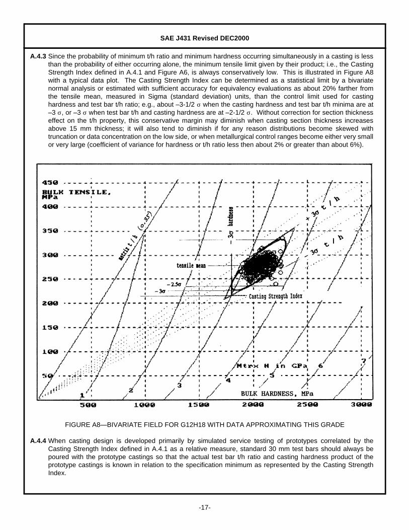
A.4.3 Since the probability of minimum t/h ratio and minimum hardness occurring simultaneously in a casting is lessthan the probability of either occurring alone, the minimum tensile limit given by their product; i.e., the CastingStrength Index defined in A.4.1 and Figure A6, is always conservatively low. This is illustrated in Figure A8with a typical data plot. The Casting Strength Index can be determined as a statistical limit by a bivariatenormal analysis or estimated with sufficient accuracy for equivalency evaluations as about 20% farther fromthe tensile mean, measured in Sigma (standard deviation) units, than the control limit used for castinghardness and test bar t/h ratio; e.g., about –3-1/2 σ when the casting hardness and test bar t/h minima are at–3 σ, or –3 σ when test bar t/h and casting hardness are at –2-1/2 σ. Without correction for section thicknesseffect on the t/h property, this conservative margin may diminish when casting section thickness increasesabove 15 mm thickness; it will also tend to diminish if for any reason distributions become skewed withtruncation or data concentration on the low side, or when metallurgical control ranges become either very smallor very large (coefficient of variance for hardness or t/h ratio less then about 2% or greater than about 6%).
FIGURE A8—BIVARIATE FIELD FOR G12H18 WITH DATA APPROXIMATING THIS GRADE
A.4.4 When casting design is developed primarily by simulated service testing of prototypes correlated by theCasting Strength Index defined in A.4.1 as a relative measure, standard 30 mm test bars should always bepoured with the prototype castings so that the actual test bar t/h ratio and casting hardness product of theprototype castings is known in relation to the specification minimum as represented by the Casting StrengthIndex.

SAE J431 Revised DEC2000
-18-
A.4.5 When casting design is based primarily on the absolute value of casting tensile strength, destructive testing ofcastings is required of prototypes during development and of production samples for ongoing control. Thecasting strength index defined in A.4.1 can however be used as a first working estimate of tensile strength bycorrecting for thickness effect on t/h as shown in the example of A.4.7. The equivalent thickness can beestimated by geometric analysis and the relation that equivalent thickness equals volume/surface ratiomultiplied by two or from solidification time, measured by thermocouple placement in prototype or productioncastings, and the Chvorinov relationship which gives equivalent thickness in mm equal to the square root ofsolidification time in seconds for cast iron in sand molds.
A.4.6 Equivalency between grades of this document and previous SAE grades can be determined from Table A4.Test bar tensile strength equivalency between grades of this and non-SAE tensile based standards can alsobe determined from Table A4. For casting grade optimization at constant tensile strength the casting strengthindex, as given in Table A4 or estimated from other limits or data in accordance with A.4.3 can be used. Forexample, if needed for a complex shape, G9H20 would provide higher castability than G10H18 with the samestrength, since casting strength index for both is 180 MPa.
A.4.7 Equivalency between SAE grades of this document and grades classified by casting tensile strength accordingto section thickness can be assessed by correcting for section sensitivity of t/h ratio as given in Figure A7,which gives t/h ratio in various sections as a percentage of the t/h ratio in 15 mm thickness or 30 mm diameter.When statistical limits are not given or insufficient data is available for statistical analysis, the equivalent SAEgrade will be that having the product of casting hardness multiplied by the corrected test bar t/h ratio equalingor exceeding the tensile strength requirements of the grade and section size being assessed. For example,SAE G13H19, with t/h corrected to section thickness of 50 mm, will ,in accordance with Figure A7, haveestimated minimum t/h ratio in the 50 mm section of 80% of 0.13, or 0.105; the corrected product of t/hmultiplied by casting hardness will be 0.105 x 1900 = 199.5 MPa, and equivalency is indicated with a graderequiring 200 MPa minimum in a 50 mm section thickness. In this case, use of the low (–3.5 σ value ) is madeto compensate for uncertainty of the statistically unknown case and for the small error introduced by thesimplifying step of applying the 80% factor to the minimum instead of average t/h.
A.4.8 Transverse Strength—Table A5 provides estimates of transverse strength and deflection as obtained for30 mm diameter test bars broken under centered transverse loading with a span of 457.2 mm (18 in) betweensupports. The test is usually performed on the as-cast bar without machining. The test is standardized underASTM A 438. The values shown in Table A5 are carried forward from previous versions of SAE J431 and aretypical of results long reported in the literature for unmachined sand cast bars and used in standards. This testis now rarely used and the data has mainly historical significance. Use of this test for any new applicationshould be based on new data obtained for the grade of iron used.
TABLE A5—ESTIMATED MINIMUMS FOR TRANSVERSE STRENGTH
SAECastingGrade
PreviousDesignation
TransverseStregnth, Minimum
kN (lb)
TransverseDeflection Minimum
mm (in)
G9H12 G1800 7.65 (1720) 3.6 (0.14)
G9H17 G2500 8.90 (2000) 4.3 (0.17)
G10H18 G3000 9.79 (2200) 5.1 (0.20)
G11H18 G3000 9.79 (2200) 5.1 (0.20)
G11H20 G3500 10.90 (2450) 6.1 (0.24)
G11H21 G4000 11.56 (2600) 6.9 (0.27)
G13H19 G4000 11.56 (2600) 6.9 (0.27)
G7H16 c G1800 h 7.65 (1720) 3.6 (0.14)
G9H17 a G2500 a 8.90 (2000) 4.3 (0.17)
G10H21 c G3500 c 10.68 (2400) 6.1 (0.24)
G11H20 b G3500 b 10.68 (2400) 6.1 (0.24)
G11H24 d G4000 d 11.56 (2600) 6.9 (0.27)
SAE J431 Revised DEC2000
-19-
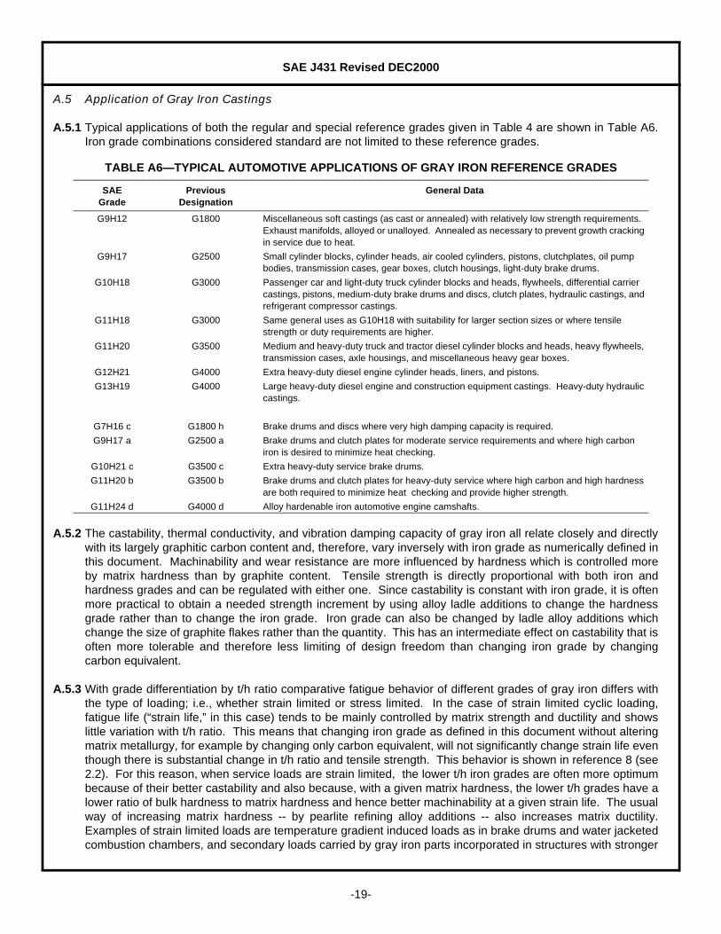
A.5 Application of Gray Iron Castings
A.5.1 Typical applications of both the regular and special reference grades given in Table 4 are shown in Table A6.Iron grade combinations considered standard are not limited to these reference grades.
A.5.2 The castability, thermal conductivity, and vibration damping capacity of gray iron all relate closely and directlywith its largely graphitic carbon content and, therefore, vary inversely with iron grade as numerically defined inthis document. Machinability and wear resistance are more influenced by hardness which is controlled moreby matrix hardness than by graphite content. Tensile strength is directly proportional with both iron andhardness grades and can be regulated with either one. Since castability is constant with iron grade, it is oftenmore practical to obtain a needed strength increment by using alloy ladle additions to change the hardnessgrade rather than to change the iron grade. Iron grade can also be changed by ladle alloy additions whichchange the size of graphite flakes rather than the quantity. This has an intermediate effect on castability that isoften more tolerable and therefore less limiting of design freedom than changing iron grade by changingcarbon equivalent.
A.5.3 With grade differentiation by t/h ratio comparative fatigue behavior of different grades of gray iron differs withthe type of loading; i.e., whether strain limited or stress limited. In the case of strain limited cyclic loading,fatigue life (“strain life,” in this case) tends to be mainly controlled by matrix strength and ductility and showslittle variation with t/h ratio. This means that changing iron grade as defined in this document without alteringmatrix metallurgy, for example by changing only carbon equivalent, will not significantly change strain life eventhough there is substantial change in t/h ratio and tensile strength. This behavior is shown in reference 8 (see2.2). For this reason, when service loads are strain limited, the lower t/h iron grades are often more optimumbecause of their better castability and also because, with a given matrix hardness, the lower t/h grades have alower ratio of bulk hardness to matrix hardness and hence better machinability at a given strain life. The usualway of increasing matrix hardness -- by pearlite refining alloy additions -- also increases matrix ductility.Examples of strain limited loads are temperature gradient induced loads as in brake drums and water jacketedcombustion chambers, and secondary loads carried by gray iron parts incorporated in structures with stronger
TABLE A6—TYPICAL AUTOMOTIVE APPLICATIONS OF GRAY IRON REFERENCE GRADES
SAEGrade
PreviousDesignation
General Data
G9H12 G1800 Miscellaneous soft castings (as cast or annealed) with relatively low strength requirements. Exhaust manifolds, alloyed or unalloyed. Annealed as necessary to prevent growth cracking in service due to heat.
G9H17 G2500 Small cylinder blocks, cylinder heads, air cooled cylinders, pistons, clutchplates, oil pump bodies, transmission cases, gear boxes, clutch housings, light-duty brake drums.
G10H18 G3000 Passenger car and light-duty truck cylinder blocks and heads, flywheels, differential carrier castings, pistons, medium-duty brake drums and discs, clutch plates, hydraulic castings, and refrigerant compressor castings.
G11H18 G3000 Same general uses as G10H18 with suitability for larger section sizes or where tensile strength or duty requirements are higher.
G11H20 G3500 Medium and heavy-duty truck and tractor diesel cylinder blocks and heads, heavy flywheels, transmission cases, axle housings, and miscellaneous heavy gear boxes.
G12H21 G4000 Extra heavy-duty diesel engine cylinder heads, liners, and pistons.
G13H19 G4000 Large heavy-duty diesel engine and construction equipment castings. Heavy-duty hydraulic castings.
G7H16 c G1800 h Brake drums and discs where very high damping capacity is required.
G9H17 a G2500 a Brake drums and clutch plates for moderate service requirements and where high carbon iron is desired to minimize heat checking.
G10H21 c G3500 c Extra heavy-duty service brake drums.
G11H20 b G3500 b Brake drums and clutch plates for heavy-duty service where high carbon and high hardness are both required to minimize heat checking and provide higher strength.
G11H24 d G4000 d Alloy hardenable iron automotive engine camshafts.
SAE J431 Revised DEC2000
-20-
components as the primary load carrying members and determinants of strain. However, fatigue life of grayiron parts subjected to stress limited loads is influenced by both t/h ratio and matrix hardness, and maximumfatigue life (“stress life”) in these cases occurs in the highest t/h and hardness grades. Typical examples ofcastings subject to stress controlled loading are engine blocks and hydraulic castings.
A.6 Special Applications of Gray Iron
A.6.1 Heavy-Duty Brake Drums and Clutch Plates—Automotive brake drums and clutch plates for heavy-dutyservice are considered special cases. Mandatory minimum limits for carbon content and matrix microstructurerequirements are given in Table 3. Typical base chemistry is given in Table A1. Alloy is normally used to meetcasting hardness requirements of grades G10H21c and G11H20b.
A.6.2 Alloy Hardenable Iron Automotive Camshafts—Alloy hardenable automotive camshafts are also consideredas special cases. Mandatory alloy content and microstuctural requirements are given in Table 3. Typical basechemistry is shown in Table A1. Typical overall composition ranges are given in Table A2.
A.6.2.1 In casting hardenable iron for camshafts, the aim is to obtain a suitable microstructure in critical locations ofthe casting and balance the composition to obtain response to induction or flame hardening. These dependnot only on the chemistry of the iron but also on the equivalent thickness and details of the melting and liquidmetal processes. In making a given casting, it is normal practice to adjust the chemistry to narrow limitswithin the ranges of Table A2.
A.6.2.2 The cam and bearing surfaces are critical performance areas of automotive camshafts. Carbide contentand metallurgical response to flame or induction hardening of the cams in terms of hardness, depth, andarea covered are specified for each part number. Requisite hardness results both from the Martensiteproduced by hardening and the presence of eutectic carbides, which approximately equal the martensite inhardness and contribute to bulk hardness both by their own hardness and by reducing eutectic graphitecontent. Apart from their contribution to hardness, some minimum limit on carbide content in the cams isalso usually necessary for a scuff resistant surface topography.

SAE J431 Revised DEC2000
Rationale—Not applicable.
Relationship of SAE Standard to ISO Standard—Not applicable.
Application—This SAE Standard covers the hardness, tensile strength, and microstructure and specialrequirements of gray iron sand molded castings used in the automotive and allied industries. Specificrequirements are provided for hardness of castings. Test bar tensile strength/Brinell hardness (t/h) ratiorequirements are provided to establish a consistent tensile strength-hardness relationship for each gradeto facilitate prediction and control of tensile strength in castings. Provision is made for specification ofspecial additional requirements of gray iron automotive castings where needed for particular applicationsand service conditions.
NOTE—This document was revised in 1993 to provide grade specific t/h control. In 1999 the document wasrevised to make SI metric units primary. To better align the grading system with long establishedproduction methods and grades produced, the previous system of grading by fixed combinations oftensile strength and hardness was changed in 1999 to a system of grading by variable combinations oftest bar t/h ratio defined and casting hardness grades. The number of hardness grades was increasedrelative to the number of previously available ranges to facilitate centering of casting mean hardness inthe specification range so that dependence of cost optimization on controlling near the low or highsides of specification ranges is minimized.
Reference Section
SAE J417—Hardness Tests and Hardness Number Conversions
ASTM A 48—Specification for Gray Iron Castings
ASTM A 247—Recommended Practice for Evaluating the Microstructure of Graphite in Iron Castings
ASTM A 438—Transverse Testing of Gray Cast Iron
ASTM E 10—Test for Brinell Hardness of Metallic Materials
ASTM E 562—Determining Volume Fraction by Systematic Manual Point Count
Metals Handbook, Vol. 1, 10th Edition, ASM International, Materials Park, OH
Cast Metals Handbook, American Foundrymen's Society, Des Plaines, IL
1981 Iron Castings Handbook, Iron Castings Society, Inc., Cleveland, OH
H.D. Angus, “Physical and Engineering Properties of Cast Iron,” British Cast Iron Research Association,Birmingham, England, 2nd Edition, 1976
“Gray, Ductile, and Malleable Iron Castings Current Capabilities,” STP-455, American Society forTesting and Materials, 100 Barr Harbor Drive, West Conshohocken, PA 19428-2959
G.N.J. Gilbert, “Engineering Data on Grey Cast Iron,” BCIRA (1977), Alvechurch, Birmingham, England
SAE J431 Revised DEC2000
“Tables for Normal Tolerance Limits, Sampling Plans and Screening,” R.E. Odeh and D.B. Owen, MarcelDekker, Inc., New York and Basel, 1980
“Fatigue Properties of Gray Cast Iron,” L.E. Tucker and D.R. Olberts, SAE Paper 690471
Developed by the SAE Iron and Steel Technical Committee Division 9—Automotive Iron and Steel Castings
Sponsored by the SAE Iron and Steel Technical Executive Committee