surgassist operations and care manual - vet
TRANSCRIPT

Model: IEG2000Operations and Care Manual
BioVision Technologies LLC

2

BioVision TechnologiesSurgAssistTM IEG2000Insufflator and Electrosurgical Generator
Operations and Care Manual
221 Corporate Circle, Suite HGolden, Colorado 80401USA
303-225-0960
biovisiontech.com
Copyright © 2009 BioVision Technologies LLC All Right Reserved.
Any reproduction of this material, in whole or in part, either through conventional orelectronic means without the express written permission of BioVision TechnologiesLLC is strictly prohibited.
3

4

Table of Contents
1. Introduction1.1 The SurgAssistTM Insufflator and Electrosurgical Generator1.2 Regulatory Compliance Info, Disclaimers, etc.1.3 Warranty Information1.4 How to Use This Manual1.5 Manual Conventions
2. Product Specifications2.1 Contents2.2 Features and Specifications2.2.1 SurgAssistTM Features2.2.2 Technical Specifications2.3 Safety Information2.3.1 General Safety Information2.3.2 Insufflator Safety Information2.3.3 Electrosurgical Generator Safety Information
3. Setup and Basic Usage3.1 Setup3.1.1 Insufflator Setup Information3.1.2 Electrosurgical Generator Setup Information3.2 Basic Usage3.2.1 Qualified Training3.2.2 General {unit-wide} Indications of Proper Usage3.2.3 Insufflator Usage3.2.4 Electrosurgical Generator Usage
4. SurgAssistTM Accessories4.1 Monopolar Electrosurgery Accessories4.2 Bipolar Electrosurgery Accessories
5. Cleaning and Maintenance5.1 Cleaning5.2 Sterilization5.3 Fuse Replacement
6. Troubleshooting
5

6
IMPORTANT
The Biovision technologies SurgAssist™ Insufflator/ElectrosurgicalGenerator has been designed to facilitate non and minimally inva-sive diagnostic and therapeutic procedures. It should be used onlyfor those procedures and only by personnel who are trained to per-form them.
This manual describes the recommended procedures for preparingand operating the SurgAssist™ . It does not describe how any medicalprocedure is to be performed on a patient with this instrument.
Read all instructions in this manual carefully before using theSurgAssist™ on patients.
Carefully follow all safety instructions to prevent fire, electricalshock, damage to this device, and injury to user and patient.
To maintain this device in optimal condition, follow all recommenda-tions in this manual for its handling, cleaning,and storage.
This equipment is strictly for veterinary use.
7

1. IntroductionThank you for your purchase of the SurgAssistTMCombination Insufflator and Electrosurgical Generator(IEG) from BioVision Technologies.
1.1 The SurgAssistTM Insufflator and Electrosurgical Generator
The SurgAssistTM system integrates two essential surgical anddiagnostic needs into a single compact & portable package:
Insufflation SystemThe SurgAssistTM Insufflator is specifically designed to fulfillall requirements for laparoscopic CO2 insufflation. It offersall essential functions needed for minimally invasive surgicalprocedures, along with BioVision Technologies’ signature“ease of use.”
Electrosurgical GeneratorThe SurgAssistTM Electrosurgical Generator is specificallydesigned for cutting and coagulating using high-frequencyRF currents. It offers all essential functions for everydayclinical practice. Both monopolar and bipolar outputs areavailable to suit various therapeutic situations.
8

1.2 Regulatory Compliance Info, Disclaimers, etc.
This device has been tested and found to comply with thelimits for a class B digital device, pursuant to Part 15 of theFCC rules. These limits are designed to provide reasonableprotection against harmful interferences in a residentialinstallation.
This equipment generates, uses, and can radiate radio fre-quency energy and, if not installed and used in accordancewith the instructions, may cause harmful interference toradio or television reception. However, there is no guaranteethat interference will not occur in a particular installation.
If this equipment does cause interference to radio andtelevision reception, which can be determined by turning theequipment on and off, the user is encouraged to try to cor-rect the interference by one or more of the following meas-ures:
- Reorient or relocate the receiving antenna.- Increase the separation between the equipment andreceiver.- Connect the equipment into an outlet on a circuitdifferent from that which the receiver is connected.
This apparatus does not exceed the Class B limits for radionoise emissions from digital apparatus as set out in the radiointerference regulations of Industry Canada.
9
1.3 Warranty Information
The BioVision Technologies SurgAssist™ Insufflator andElectrosurgical Generator (IEG2000), when delivered to you in newcondition in the original container, is warranted to be free fromdefects in material or workmanship for one year from the date ofshipment to you by the distributor, upon proof of date. Within thistime period, parts that are returned, freight prepaid, to BioVisionTechnologies LLC (“BioVision Technologies or BioVision”) and aredetermined by BioVision Technologies to be defective will berepaired or replaced by BioVision Technologies without charge forparts, labor, or return ground shipping costs. BioVisionTechnologies will make every effort to accomplish this repair orreplacement within a reasonable time. After the warranty period,you must pay all charges for repair and replacement. This warrantydoes not cover light bulbs or other consumable items.
The above actions by BioVision Technologies shall constitute yourexclusive remedy and BioVision Technologies’s sole obligationunder this warranty. BioVision Technologies shall not be responsi-ble for warranty claims made after the warranty period. To obtainwarranty repair service, you must contact Biovision technologies toobtain a Return Material Authorization (“RMA”) number, thenreturn the product, freight prepaid, to BioVision Technologies or toa service facility authorized by BioVision Technologies. The RMAnumber and a complete explanation of the problem must be includ-ed with the product being returned to BioVision Technologies forwarranty service. The product to be repaired must be returned inits original box and packaging, or a similar box and packagingaffording an equivalent degree of protection. Upon completion ofrepairs, BioVision Technologies will return the product to you,freight prepaid.
The warranty period for replacement parts shall begin upon ship-ment of same, but shall in no event exceed the warranty period ofthe defective part. BioVision Technologies shall have no liability orobligation for a product that has been subjected to any of the fol-lowing: improper use, abuse, negligent care or handling, accident,faulty installation, improper cleaning, improper maintenance,lightning or other indications of excess voltage.This warranty is also void if the product has been repaired or modi-fied without prior written authorization from Biovision technolo-gies, if the end-user has failed to follow the instructions or heed thewarnings or specifications in the Operation and Care Manual, or ifthe product’s serial number has been altered or removed.
10

EXCEPT FOR THE FOREGOINGWARRANTIES, BIOVI-SION TECHNOLOGIES HEREBY DISCLAIMS ANDEXCLUDES ALL OTHERWARRANTIES, EXPRESS ORIMPLIED, INCLUDING BUT NOT LIMITED TO ANYAND/OR ALL IMPLIED WARRANTIES OF MER-CHANTABILITY OR FITNESS FOR A PARTICULAR PUR-POSE. BIOVISION TECHNOLOGIES HEREBY DIS-CLAIMS ANY REPRESENTATIONS ORWARRANTYTHAT THIS PRODUCT OR ANY OF ITS PARTS IS COM-PATIBLE WITH NON-BIOVISION TECHNOLOGIESPRODUCTS OTHER THAN VIDEO EQUIPMENTATTACHED TO ITS VIDEO OUTPUTS, AS DESCRIBEDIN THE OPERATOR’S MANUAL. THE LIABILITY OFBIOVISION TECHNOLOGIES, IF ANY, AND PURCHAS-ER’S SOLE AND EXCLUSIVE REMEDY FOR DAMAGESFOR ANY CLAIM OF ANY KINDWHATSOEVER,REGARDLESS OF THE LEGAL THEORY, SHALL NOT BEGREATER IN AMOUNT THAN THE PURCHASE PRICEOF THE PRODUCT SOLD BY BIOVISION TECHNOLO-GIES THAT CAUSED ANY ALLEGED DAMAGE. IN NOEVENT SHALL BIOVISION TECHNOLOGIES BE LIABLETO PURCHASER FOR ANY SPECIAL, INDIRECT, INCI-DENTAL, OR CONSEQUENTIAL DAMAGES OF ANYKIND.
11

1.4 How to Use This ManualThe intention of the document is to convey the proper andprescribed operation and care of the SurgAssistTM IEG2000Insufflator/Electrosurgical Generator
1.5Manual Conventions
This manual adheres to a set of conventions to help you easi-ly find the information you need and inform you of impor-tant information that will help you efficiently and effectivelyuse your equipment.
Sections and sub sections are noted as follows:
1. Section Title
1.1 Subsection title
Special and important information is called out using notesand warnings. Notes usually pertain to a recommended pro-tocol that will help extend the life of your equipment.Warnings pertain to protocols that delineate appropriateactions which maintain a safe and healthy work environ-ment.
Notes and warnings are called out in the following manners:
Note: This is a note.
WARNING: This is a warning.
12

2. Product SpecificationsThe following section describes the components and featuresof the SurgAssistTM system.
2.1 ContentsThe following components are included in your SurgAssistTMsystem:
SurgAssistTM Insufflator/Electrosurgical Generator
Medical Grade Power cord
Hoses1 CO2 input hose1 CO2 output, insufflation hose
Saddle and regulator for “E” tank
Footswitch
Patient Grounding Plate
Check to see that you have all of these components beforeproceeding. If any of these components are missing, contactBioVision Technologies immediately using the contact infor-mation below.
BioVision Technologies221 Corporate CircleSuite HGolden, Colorado USA 80401
Phone: 303.225.0960Fax: 303.237.0757
13

2.2 Features and Specifications
2.2.1 Features
Front - Insufflator
Front- Electrosurgical Generator
14
PatientPressure Gauge
Flow Rate Gauge
Liters DeliveredGauge
(Gas Gauge)
Fill Button
Auto/Manualflow switch
InsufflationOn/Off Switch
Insufflator output
Bipolar ModeIndicator
Bipolar Power LevelMode Selector
Monopolar ModeIndicator
MonopolarPower Level
Patient PlateConnectors
Waveform SelectorSystem Power
IndicatorBipolar Output
Monopolar Output

Rear
15
Foot SwitchConnector
CO2 Input(from “E” Tank)
Pressure LevelIndicator Switch
System PowerSwitch
System A/C Input
Insufflator Item DescriptionPatient Pressure Gauge Pneumoperitenium in mmHg.Flow Gauge Rate of CO2 release to patient.Liters Delivered Remaining capacity of internal tank.Auto/Manual Flow SwitchCO2 flow to patient.Fill Button Refills internal tank from “E” tank
(applies only to Manual flow).Insufflation On/Off Turns insufflation output on or off.Insufflation Output Connects to patient via insufflation hose
Electrosurgical Generator Item DescriptionBipolar Mode Indicator Indicates the bipolar mode is selected.Bipolar Power Level Controls bipolar output power.Mode Selector Selects between Monopolar and Bipolar.Monopolar Mode Ind. Indicates the monopolar mode is selected.Monopolar Power Level Controls monopolar output power.Monopolar Output Connects to monopolar handpiecePatient Plate Connectors Connect to patient plate.Waveform Selector Selects Cut, Blend or Coag waveform.System Power Indicator Lights when system power is on.Bipolar Output Connects to bipolar handpieces.
Rear Item DescriptionFootswitch Connector Snap connector for footswitchCO2 Input Snap connector for hose from CO2 “E” tankPatient Pressure Select Selects high or low patient pressure.Pressure Level Indicator Bypasses over/under pressure indicatorsSystem Power Switch Turns the SurgAssistTM unit on and off.System A/C Input Connects to wall A/C via medical grade cord
Patient PressureSelect Switch
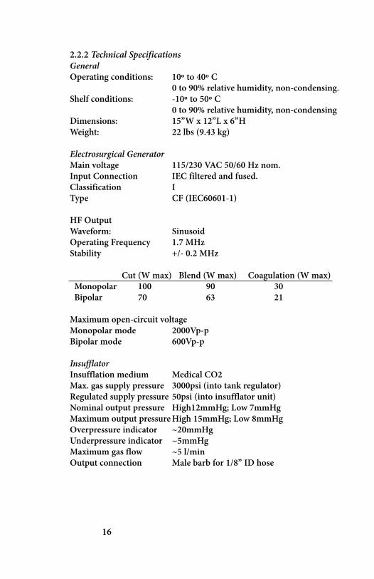
2.2.2 Technical SpecificationsGeneralOperating conditions: 10º to 40º C
0 to 90% relative humidity, non-condensing.Shelf conditions: -10º to 50º C
0 to 90% relative humidity, non-condensingDimensions: 15”W x 12”L x 6”HWeight: 22 lbs (9.43 kg)
Electrosurgical GeneratorMain voltage 115/230 VAC 50/60 Hz nom.Input Connection IEC filtered and fused.Classification IType CF (IEC60601-1)
HF OutputWaveform: SinusoidOperating Frequency 1.7 MHzStability +/- 0.2 MHz
Cut (W max) Blend (W max) Coagulation (W max)Monopolar 100 90 30Bipolar 70 63 21
Maximum open-circuit voltageMonopolar mode 2000Vp-pBipolar mode 600Vp-p
InsufflatorInsufflation medium Medical CO2Max. gas supply pressure 3000psi (into tank regulator)Regulated supply pressure 50psi (into insufflator unit)Nominal output pressure High12mmHg; Low 7mmHgMaximum output pressureHigh 15mmHg; Low 8mmHgOverpressure indicator ~20mmHgUnderpressure indicator ~5mmHgMaximum gas flow ~5 l/minOutput connection Male barb for 1/8” ID hose
16

2.3 Safety Information
It is important that you read, understand, and comply withall of the following safety precautions.
Failure to follow these precautions could result in injury tothe patient or user, or damage to the SurgAssistTM unit.
2.3.1 General Safety Information
Keep the SurgAssistTM unit on a flat, level, and secure surface.
Be sure to leave sufficient clearance for ventilation by notplacing any other equipment or objects on, in front of, ornear the vents on either side of the SurgAssistTM unit.
Do not set the SurgAssistTM on another soft or other wisesmothering surface such as clothing, fabric or towels. Thiswill interfere with the unit’s ability to cool itself.
Do not allow liquids on the SurgAssistTM unit.
Only use medical-grade power cords and power outlets withthe SurgAssistTM unit.
Be sure to sterilize the hoses and all parts of the SurgAssistTMunit that come in contact with patients using the sterilizationprocedures described in this manual.
Always disconnect the SurgAssistTM unit from its powersource when performing maintenance (e.g. cleaning, replac-ing fuses, etc.).
17
Manufactured and tested according toUL2601 and IEC60601-1Complies with EN60601-1-2, group 2, Class B,and FCC Part 15 EMC requirements.

2.3.2 Insufflator Safety Information
WARNING: The CO2 gas in an “E” tank is under extremely high pressure.
Follow all prescribed procedures for handling high pressure CO2tanks. These can be obtained by your gas vendor.
Note: Use caution when disconnecting the CO2 supply hose from the rear
of the SurgAssistTM unit. The pressure in the use may cause the hoseto eject from the SurgAssistTM connector with unexpected force.
When the procedure is finished, close the top valve on the “E”tank to prevent leaking of the gas.
Note: If taking the SurgAssistTM unit on an airplane, be sure to empty theinternal tank by leaving the Power switch ON.
2.3.3 Electrosurgical Generator Safety Information
When performing monopolar electrosurgery, be sure to place agrounding plate on or under the patient before starting any pro-cedure. Failure to do this can cause excessive burning of patienttissue.
WARNING: The grounding plate cannot come in contact with the operat-ing table or any othermetal object. If the grounding plate does con-tact any metal, it can seriously injure or electrocute the patient.
Always ensure that all connections to the electrosurgical genera-tor are secure and free from debris and any standing or con-densing moisture.
3. Setup and Basic UsageThe following section describes how to set up and use theSurgAssistTM system for most basic surgical procedures.
3.1 System SetupStart by placing the SurgAssistTM unit on a flat, level, and securesurface.
Be sure to leave sufficient clearance (at least 4 inches) for venti-lation by not placing any other equipment or objects on, infront of, or near the vents on the SurgAssistTM unit. Do not seton any soft or conforming material such as towels or drapes that
18

will block ventilation to the bottom of the unit.Ensure the footswitch is connected to the rear of the unit. The“L” shaped connector will point out, away from the label on therear of the unit.
Connect the medical-grade power cord for the SurgAssistTM unitto an outlet that has also been approved for medical use.
Turn on the SurgAssistTM unit by turning the Power switch onthe rear of the SurgAssistTM unit to “On.” The power light underthe waveform selector on the front of the generator should beilluminated at this point.
3.1.1 Insufflator Setup Information
Assemble the regulator and CO2 supply hose. One end of thesupply hose has a quick connector (white tip and O-ring). Theother end has a large nut for connecting to the regulator.Thread this nut connector onto the regulator being careful notto cross-thread the nut. Cross-threading can produce a CO2 gasleak. Snug the connection with two wrenches. Do not overtighten.
Connect the regulator to the external “E” CO2 tank. Examinethe valve at the top of the “E” tank. The square area on thevalve should have two opposing smooth sides and one side withthree holes and one side with a divot. Hold the regulator so thatthe pressure gauge is up and slide the saddle over the valve lin-ing up the saddle’s “T” knob with the divot and the two pins onthe opposite side fit into the bottom two holes. Push the saddleinto the side with three holes and tighten the “T” knob into thedivot. The “T” knob may need further tightening if CO2 leakswhen the “E” tank valve is opened.
Connect the quick connect end of the supply hose to the CO2input on the back of the SurgAssistTM (see page 15). The tab onthis outlet will pop up in order to lock the hose in place. (If youencounter difficulty connecting the hose to the unit, check thatthe latch tab is “set“, by pushing it toward the connector bodyuntil a click is heard.)
To allow CO2 to flow to the SurgAssistTM, use a tank wrench(can be supplied by your gas vendor) to open the valve stem onthe top of the tank. This is a standard system: counterclockwise
19

to open and clockwise to close.
Select the desired operating pressure with the Patient PressureSelect switch (see page 15). Select either low or high, pressuresetting. The preset pressures are nominally 7mmHg (low) and12 mmHg (high) respectively.
Connect the female end of the 1/8” ID hose to the “Output”male barb on the front of the Insufflator (See page 14).Note: The under pressure indicator at 5 mmHg and the overpressure indicator at 20mmHg may be bypassed according todoctor preference. To bypass, turn the Pressure Level Indicatorswitch on the back of the SurgAssistTM unit to Off (See page 15).
To disconnect the regulator/hose, pull up the tab on top of theoutlet. This will cause the hose to (gently) “pop out.”
3.1.2 Electrosurgical Generator Setup Information
Attach the connector of the Foot Switch to the “Foot Switch”outlet on the back of the Generator.
Note: The waveform selector selects an energy waveform for a particulartask. Cut to separate tissue and coag to cauterize tissue. Blend is acombination of cut and coag and perform both functions simultane-ously.
For Monopolar Electrosurgery:
Begin by placing a ground plate on or under the patient. Failureto do this can cause excessive burning of patient tissue.
Attach the two electrical connectors of the ground plate to thetwo black (lower) “Monopolar Output” outlets on the front ofthe generator (See page 14).
Attach the power end of the monopolar surgical instrument tothe green (upper) “Monopolar Output” outlet on the front ofthe Generator (See page 14).
Turn the mode selector switch to the left for MonopolarElectrosurgery.
Adjust the Monopolar Power Level knob to the desired level.
20

Energy is applied to the handunit when stepping down on thefootswitch.Should one or both connections to the grounding plate becomedisconnected, an audible indicator will sound, and no electricalcurrent will flow to the handpiece.
Energy is applied to the handunit when stepping down on thefootswitch
For Bipolar Electrosurgery:Attach the two electrical connectors of the bipolar surgicalinstrument to the “Bipolar Output” (blue) outlets on front ofthe generator (See page 14).
Turn the Selector switch to the right for Bipolar Electrosurgery.
Adjust the Bipolar Power Level knob to the desired level.
Energy is applied to the hand unit when stepping down on thefootswitch.
3.2 Basic UsageThe following section describes basic usage of the SurgAssistTMUnit.
3.2.1 Qualified TrainingOnly personnel qualified to perform a specific procedure, diag-nostic or therapeutic, should perform the procedures. BioVisionTechnologies always advocates the application of qualifiedtraining before attempting any procedure. Qualified trainingand Continuing Education is available through BioVisionTechnologies and many other channels. If you purchased thisunit as a part of a BioVision Technologies EndoDiagnostic andSurgical Suite, training is included in the price of the suite. Ifyou do not feel comfortable with a procedure, please seek addi-tional training.
3.2.2 General Proper UsageThe SurgAssistTM system is designed to support minimally inva-sive and some general surgical procedures. Usage is suggestedwhen either abdominal distention for surgery or electrocauteryis desired.
21

3.2.3 Insufflator Usage
(for Manual Flow only)
Before performing insufflation, first fill the SurgAssistTM unit’sinternal CO2 tank. Do this by pressing the yellow “Fill” buttonuntil the “Liters Delivered” gauge reads 0. This means thatnone of the CO2 in the internal tank has been used yet forinsufflation.
(for Auto Fill)The “Fill” button is not necessary, CO2 is automatically deliv-ered from the external E-tank via the internal CO2 tank to thepatient.
Before selecting the “Auto Fill” or “Manual Fill” mode, firstchoose the desired patient pressure for insufflation by select-ing “High” or “Low” using the patient pressure select switch(See page 15). The selected patient pressure (in mm Hg) willappear on the “patient pressure gauge” on the front right sideof the insufflator panel.
To begin insufflation, turn the “On/Off” switch (on the frontof the Insufflator panel) to “On.” CO2 will begin flowing intothe patient at the rate shown on the “Flow Rate” gauge.
Note: During insufflation, be sure to pay close attention to the“Patient Pressure” gauge in order to avoid too much pressureinside the patient cavity.
Insufflation occurs automatically until 15 (high) or 8 (low)mmHg of pressure is reached (this reading may vary slightlywith altitude). The application of additional/external pressureon the abdomen (e.g. by creating another incision, insertinganother instrument, etc.) will cause patient pressure to spikeupwards, and the “Pressure Indicators” may sound.
3.2.4 Electrosurgical Generator Usage
For Monopolar Surgery:Ensure the you have followed the “For Monopolar Surgery”directions in section 3.2.1.
22

Start your procedure at a low power setting and increase thepower until the desired cutting/hemostasis is accomplished.Trying different energy waveform setting may also helpaccomplish desirable results.
For Bipolar Electrosurgery:Ensure the you have followed the “For Bipolar Surgery” direc-tions in section 3.2.1.
Again, start with a low power setting and adjust the power andenergy waveform knobs to produce the desired results.
Note: In most cases, it is best to leave this knob on the “Blend” set-ting. This provides the proper wavelength for either cutting orcoagulating without having to manually switch between the twomodes.
4. SurgAssistTM AccessoriesThe following section describes how to set up and use the vari-ous accessories available for SurgAssistTM system.
4.1Monopolar Electrosurgery AccessoriesThe SurgAssistTM monopolar generator is compatible with mostmonopolar hand instruments. Hand pieces with a 4mm“banana” connector are designated as footswitch operated, andare usually compatible. This unit is incompatible with ValleyLab monopolar handpieces.
4.2 Bipolar Electrosurgery AccessoriesThe SurgAssistTM bipolar generator is compatible with mostbipolar hand instruments that terminate in dual 4mm“banana” connectors. This unit is incompatible withLigaSureTM handpieces.
5. Cleaning and MaintenanceThe following section described the proper method(s) forcleaning and maintaining your SurgAssistTM system.
Note: Never immerse or soak any part of the SurgAssistTM unit in anyliquid, as this can cause significant damage not covered by thewarranty.
5.1 General Cleaning of SurgAssistTM Unit
23

Use a lightly damp cloth. Wipe down the entire SurgAssistTMunit with it.
Allow the unit to dry before using it again.
Any blood on the SurgAssistTM unit can be removed using cot-ton or gauze soaked in alcohol.5.2 SterilizationSterilize electrosurgical handpieces according to manufactur-er’s instructions.
The patient plate does not normally need to be sterilized.Should you need to sterilize your patient plate, please contactBioVision Technologies for the best sterilization procedure.
The supplied insufflation hose (SurgAssistTM to patient) is ster-ilizable by Ethylene Oxide. Ensure that the sterilized pack con-taining the hose is sufficiently ventilated to prevent any resid-ual ethylene oxide contact with you, your staff or your patient.
5.3 Fuse Replacement
1. Use a flat screw-driver in the slot atthe top of the fusecover.
2. Swing cover downto reveal fuse holder.Cover will notdetach.
24

3. Use screwdriver togently pry the fuseholder out of theunit.
4. Replace the fusesand observe the cor-rect replacement ori-entation.
Replace with 3.15A,250V Type F fusesonly.
5. Re-insert the fuseholder.
25

6. Close the fusecover.
7. Ensure that “115” isshowing through thewindow.
Note: If 230 VAC isrequired, then followthe above procedure,but be sure to turn thefuse holder upside-down before re-insert-ing it. Ensure that“230” is showingthrough the window.
26

6. Troubleshooting
Scenario:
A. No insufflation
No Flow, No Patient Pressure Turn insuffla-tion on.
Fill internal CO2 tank.
Flow, No Patient Pressure Leak: check gas egress.
No Flow, Patient Pressure Closed valve: turn onvalves and stopcocks.
Should these measures fail, call BioVision Technologiesfor further technical support.
B. Cannot fill internal tank
1. Check Supply Hose, check for proper connection.
2. Turn on “E” Tank valve using tank wrench
3. Replace “E” Tank
Should these measures fail, call BioVision Technologiesfor further technical support.
C. Pressure indicators not heard
1. Turn on unit. System power must be on for theindicators to operate.
2. Turn on indicators on the rear panel of the unit.
Should these measures fail, call BioVision Technologiesfor further technical support.
27

D. No electrocautery/cutting
1. Turn on unit using the power switch on the rear ofthe unit.
2. Select proper mode
3. Turn up proper power level
4. Change energy waveform
5. Check electrical connectors
6. Replace handpiece
Should these measures fail, call BioVision Technologiesfor further technical support.
BioVision Technologies Customer CarePhone: 303.225.0960Email: [email protected]
Please copy your serial number here forfuture reference:
28

29

30
BioVision Technologies LLC221 Corporate CircleSuite HGolden, Colorado 80401USA
Copyright © 2009 BioVision Technologies LLCAll Rights ReservedBVT93565-00001-D
032509