surge arrester - finmotor · am series surge arrester class i the enerdoor surge arrester am series...
TRANSCRIPT

Surge Arrester


Surge Arresters | Safe and Reliable Protection for Electrical EquipmentThe Enerdoor surge arrester series has been specifically designed to protect electrical equipment. Surge arresters are installed at thefront end of a system for the purpose of diverting harmful overvoltage transients caused by external (lightning) and/or internal(switching) events to ground safely. Also known as Surge Protection Device (SPD), or Transient Voltage Surge Suppressor (TVSS),Enerdoor surge arrestors protect against electrical transients resulting from lightning strikes that find their way onto electricalconductors.All models include remote contact, visual indicator, and comply with the UL 1449, IEC 61643-11, and VDE 0675 InternationalStandards. DIN rail or screw mounting options are available with select models offering plug and play replaceable cards for quick andeasy installation and replacement.
Types of Surge ArrestersSurge arresters are divided by zone:
Example of main supply
Recommended max cable lengthfor surge arrester in branch circuits
LZP 0A External zone exposed to direct lightning strikes Full lightning current andunattenuated electric field
LZP 0B External zone within lightning prevention system (LPS) and Part of the lightning currentprotected against direct strikes and unattenuated electric field
LZP 1 Internal zone where surge is limited by current spreading, Low currents andup‐stream SPDs and screening attenuated electric fields
LZP 2 Internal zone where surge is less than LZP 1 due to current Minimum currents andspreading, screening and up‐stream SPDs very attenuated electric fields
ZONE CHARACTERISTICS SURGES
Lightning
Operations
Irms
Voltage
INTRODUCTION 3
INTRODUCTION
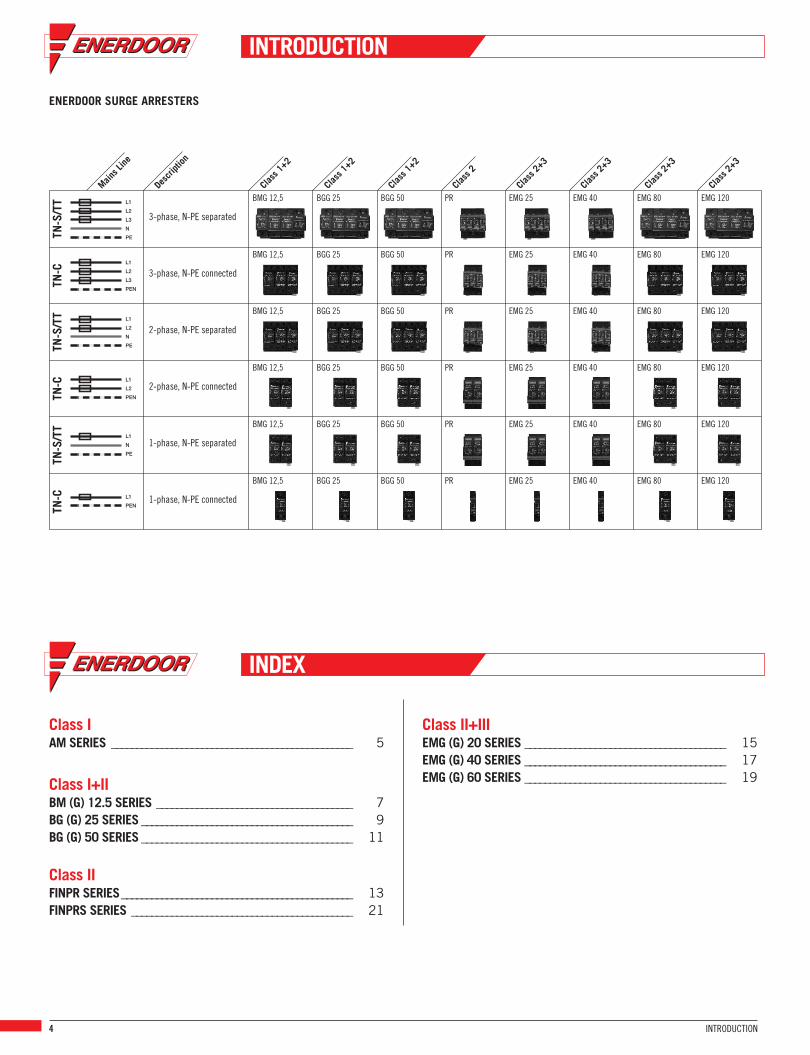
ENERDOOR SURGE ARRESTERS
3-phase, N-PE separated
3-phase, N-PE connected
2-phase, N-PE separated
2-phase, N-PE connected
1-phase, N-PE separated
1-phase, N-PE connected
BMG 12,5 BGG 25 BGG 50 PR EMG 25 EMG 40 EMG 80 EMG 120
BMG 12,5 BGG 25 BGG 50 PR EMG 25 EMG 40 EMG 80 EMG 120
BMG 12,5 BGG 25 BGG 50 PR EMG 25 EMG 40 EMG 80 EMG 120
BMG 12,5 BGG 25 BGG 50 PR EMG 25 EMG 40 EMG 80 EMG 120
BMG 12,5 BGG 25 BGG 50 PR EMG 25 EMG 40 EMG 80 EMG 120
BMG 12,5 BGG 25 BGG 50 PR EMG 25 EMG 40 EMG 80 EMG 120
TN-S/TT
TN-C
TN-S/TT
TN-C
TN-S/TT
TN-C
Class 1+2
Description
Mains Line
Class 1+2
Class 1+2
Class 2
Class 2+3
Class 2+3
Class 2+3
Class 2+3
L1
L2
L3
N
PE
L1
L2
N
PE
L1
N
PE
L1
L2
L3
PEN
L1
L2
PEN
L1
PEN
INTRODUCTION
INDEX
4 INTRODUCTION
Class IAM SERIES _ _ _ _ _ _ _ _ _ _ _ _ _ _ _ _ _ _ _ _ _ _ _ _ _ _ _ _ _ _ _ _ _ _ _ _ _ _ _ _ _ _ _ _ _ _ _ _ 5
Class I+IIBM (G) 12.5 SERIES _ _ _ _ _ _ _ _ _ _ _ _ _ _ _ _ _ _ _ _ _ _ _ _ _ _ _ _ _ _ _ _ _ _ _ _ _ _ _ 7BG (G) 25 SERIES _ _ _ _ _ _ _ _ _ _ _ _ _ _ _ _ _ _ _ _ _ _ _ _ _ _ _ _ _ _ _ _ _ _ _ _ _ _ _ _ _ _ 9BG (G) 50 SERIES _ _ _ _ _ _ _ _ _ _ _ _ _ _ _ _ _ _ _ _ _ _ _ _ _ _ _ _ _ _ _ _ _ _ _ _ _ _ _ _ _ _ 11
Class IIFINPR SERIES _ _ _ _ _ _ _ _ _ _ _ _ _ _ _ _ _ _ _ _ _ _ _ _ _ _ _ _ _ _ _ _ _ _ _ _ _ _ _ _ _ _ _ _ _ _ 13FINPRS SERIES _ _ _ _ _ _ _ _ _ _ _ _ _ _ _ _ _ _ _ _ _ _ _ _ _ _ _ _ _ _ _ _ _ _ _ _ _ _ _ _ _ _ _ _ 21
Class II+IIIEMG (G) 20 SERIES _ _ _ _ _ _ _ _ _ _ _ _ _ _ _ _ _ _ _ _ _ _ _ _ _ _ _ _ _ _ _ _ _ _ _ _ _ _ _ _ 15EMG (G) 40 SERIES _ _ _ _ _ _ _ _ _ _ _ _ _ _ _ _ _ _ _ _ _ _ _ _ _ _ _ _ _ _ _ _ _ _ _ _ _ _ _ _ 17EMG (G) 60 SERIES _ _ _ _ _ _ _ _ _ _ _ _ _ _ _ _ _ _ _ _ _ _ _ _ _ _ _ _ _ _ _ _ _ _ _ _ _ _ _ _ 19

Surge Arrester Class IAM SERIES
The Enerdoor surge arrester AM series provides advanced surge protection. This device is designed for maximum discharge of300 kA. As a standard this series is offered in a metal enclosure and includes a visual indicator and optional remote alarm.
GENERAL CHARACTERISTICS
SCCR 200 kALightening counter current >200 kAFail pre‐test Press 2 sec reset buttonProtection L‐N, N‐PE, L‐PEPower status indication Normal = Power LED ONWorking status indication Normal = Blue LED ON
Fail = Red LED ONPower connecting cable 8 AWG (L1=yellow, L2=green, L3=red
N=blue, PE=black)Signal cable 16 AWG (C=red, NC=blue, NO=brown)Working enviroments Temperature (‐40°C + 70°C, Humidity relative
up to 95% (25°C), altitude <2000 meter)Dimensions WxDxH (in mm) 256 x 205 x 104Net weight 5.4 Kg
AM System Voltage (50/60Hz)Protection Mode
Voltage Protection Rated(VPR@6KV/3KA)
L-N L-PE N-PE L-L L-N L-PE N-PE L-L PHASE MODE
Surge Capability KA MaxContinuosVoltage
AM120SP100-5 120/240 split (fig.1) - 800 800 800 1200 100 50 180
AM120SP200-5 120/240 split (fig.1) - 800 800 800 1200 200 100 180
AM120SP300-5 120/240 split (fig.1) - 800 800 800 1200 300 150 180
AM127Y100-7 220Y127 WYE (fig.2) - 800 800 800 1200 100 50 180
AM127Y200-7 220Y127 WYE (fig.2) - 800 800 800 1200 200 100 180
AM127Y300-7 220Y127 WYE (fig.2) - 800 800 800 1200 300 150 180
AM220Y100-7S 380Y220 WYE (fig.2) - 1200 1200 1200 2000 100 50 320
AM220Y200-7S 380Y220 WYE (fig.2) - 1200 1200 1200 2000 200 100 320
AM220Y300-7S 380Y220 WYE (fig.2) - 1200 1200 1200 2000 300 150 320
AM277Y100-7 480Y277 WYE (fig.2) - 1200 1200 1200 2000 100 50 320
AM277Y200-7 480Y277 WYE (fig.2) - 1200 1200 1200 2000 200 100 320
AM277Y300-7 480Y277 WYE (fig.2) - 1200 1200 1200 2000 300 150 320
AM347Y100-7 600Y347 WYE (fig.2) - 1500 1500 1500 2500 100 50 420
AM347Y200-7 600Y347 WYE (fig.2) - 1500 1500 1500 2500 200 100 420
AM347Y300-7 600Y347 WYE (fig.2) - 1500 1500 1500 2500 300 150 420
AM120H100-7 120/240 H�LEG (fig.3) - 1000 1000 800 1500 100 50 180/275
SURGE ARRESTER CLASS I 5

Surge Arrester Class IAM SERIES
AM System Voltage (50/60Hz)Protection Mode
Voltage Protection Rated(VPR@6KV/3KA)
L-N L-PE N-PE L-L L-N L-PE N-PE L-L PHASE MODE
Surge Capability KA MaxContinuosVoltage
AM120H200-7 120/240 H�LEG (fig.3) - 1000 1000 800 1500 100 50 180/275
AM120H300-7 120/240 H�LEG (fig.3) - 1000 1000 800 1500 100 50 180/275
AM240D100-6S 240 Delta (fig.4) - - - 1200 - 1400 100 50 320
AM240D200-6S 240 Delta (fig.4) - - - 1200 - 1400 200 100 320
AM240D300-6S 240 Delta (fig.4) - - - 1200 - 1400 300 150 320
AM480D100-6S 480 Delta (fig.4) - - - 1900 - 2200 100 50 550
AM480D200-6S 480 Delta (fig.4) - - - 1900 - 2200 200 100 550
AM480D300-6S 480 Delta (fig.4) - - - 1900 - 2200 300 150 550
AM600D100-6S 600 Delta (fig.4) - - - 2400 - 2800 100 50 690
AM600D200-6S 600 Delta (fig.4) - - - 2400 - 2800 200 100 690
AM600D300-6S 600 Delta (fig.4) - - - 2400 - 2900 300 150 690
AM127S100-3 127 Single (fig. 5) - 800 800 800 - 100 50 180
AM127S200-3 127 Single (fig. 5) - 800 800 800 - 200 100 180
AM127S300-3 127 Single (fig. 5) - 800 800 800 - 300 150 180
AM240S1003S 240 Single (fig. 5) - 1200 1200 1200 - 100 50 320
AM240S200-3S 240 Single (fig. 5) - 1200 1200 1200 - 200 100 320
AM240S300-3S 240 Single (fig. 5) - 1200 1200 120 - 300 150 320
SPLIT2 Hots, 1 Neu, 1 Grnd
Figure 1
WYE3 Hots, 1 Neu, 1 Grnd
Figure 2
HI-LEG DELTA (B High)3 Hots, (B HIGH),1 Neu, 1 Grnd
Figure 3
DELTA & HRG WYE3 Hots, 1 Grnd
Figure 4
SINGLE POLE1 Hot, 1 Neu, 1 Grnd
Figure 5
6 SURGE ARRESTER CLASS I

BM (G) 12.5
Surge Arrester Class I+IIBM (G) 12.5 SERIES
The Enerdoor surge arrester BM (G) 12.5 series provides advanced surge protection. This device is designed for maximumdischarge of L‐N 65 kA and N‐PE 100 kA, meets the UL 1449 3rd edition and IEC61643‐11:2011 Standards, and includesa visual and remote contact indicator.
Max ContinuousOperation Voltage
NPE - Vac
NominalDischarge(In, KA) 8/20
Max DischargeCurrent(Imax, KA)
L-N N-PE L-N N-PE LN@In L-N@VPR NPE (1.2/50)
Voltage Protection Rated (kV)Case
BM.150�1P12.5 150 - 12.5 - 65 - <0.7 <0.6 - 1
BM.275�1P12.5 275 - 12.5 - 65 - <1.0 <0.8 - 1
BM.320�1P12.5 320 - 12.5 - 65 - <1.4 <1.2 - 1
BM.385�1P12.5 385 - 12.5 - 80 - <1.6 <1.4 - 1
BM.420�1P12.5 420 - 12.5 - 80 - <1.8 <1.5 - 1
BMG.150�2P12.5�N25 208 (150) 150 12.5 25 65 100 <0.7 <0.6 <0.8 2
BMG.150�2P12.5�N50 208 (150) 150 12.5 50 65 100 <0.7 <0.6 <0.8 2
BMG.275�2P12.5�N25 320 (275) 150 12.5 25 65 100 <1.0 <0.8 <1.5 2
BMG.275�2P12.5�N50 320 (275) 150 12.5 50 65 100 <1.0 <0.8 <1.5 2
BMG.320�2P12.5�N25 400 (320) 255 12.5 25 65 100 <1.4 <1.2 <1.5 2
BMG.320�2P12.5�N50 400 (320) 255 12.5 50 65 100 <1.4 <1.2 <1.5 2
BMG.385�2P12.5�N25 480 (385) 255 12.5 25 80 100 <1.6 <1.4 <1.5 2
BMG.385�2P12.5�N50 480 (385) 255 12.5 50 80 100 <1.6 <1.4 <1.5 2
BMG.420�2P12.5�N25 600 (420) 255 12.5 25 80 100 <1.8 <1.5 <1.5 2
BMG.420�2P12.5�N50 600 (420) 255 12.5 50 80 100 <1.8 <1.5 <1.5 2
BMG.150�3P12.5�N25 208 (150) 150 12.5 25 65 100 <0.7 <0.6 <0.8 3
BMG.150�3P12.5�N50 208 (150) 150 12.5 50 65 100 <0.7 <0.6 <0.8 3
BMG.275�3P12.5�N25 320 (275) 150 12.5 25 65 100 <1.0 <0.8 <1.5 3
BMG.275�3P12.5�N50 320 (275) 150 12.5 50 65 100 <1.0 <0.8 <1.5 3
BMG.320�3P12.5�N25 400 (320) 255 12.5 25 65 100 <1.4 <1.2 <1.5 3
BMG.320�3P12.5�N50 400 (320) 255 12.5 50 65 100 <1.4 <1.2 <1.5 3
BMG.385�3P12.5�N25 480 (385) 255 12.5 25 80 100 <1.6 <1.4 <1.5 3
BMG.385�3P12.5�N50 480 (385) 255 12.5 50 80 100 <1.6 <1.4 <1.5 3
BMG.420�3P12.5�N25 600 (420) 255 12.5 25 80 100 <1.8 <1.5 <1.5 3
BMG.420�3P12.5�N50 600 (420) 255 12.5 50 80 100 <1.8 <1.5 <1.5 3
GENERAL CHARACTERISTICS
Class category IEC/VDE I + II / B+COperating temperature range ‐40°C + 80°COperating humidity range 0 ~ 90%Response time L‐N (N‐PE) ≤25 ns (<100ns)Backup fuse 250 Amps gL/gG(only required if not in the main)Flow current L‐N No
N‐PE If 100 Arms @ 255 VacEnclosure material Thermoplastic, UL94 V‐0Mounting 35mm DIN rail according to the
EN50022/DIN46277-3 StandardMax size of connecting wire Single‐strand 35mm2 (or # 2AWG)
Multi‐strand 25mm2 (or # 4AWG)Remote alarm contact type Isolated form CSwitching capability Un/In AC: 250V/0.5A
DC: 250V/0.1AMax size of connecting wire Max 1.5mm2 (or #16AWG)
SURGE ARRESTER CLASS I+II 7
Nominal VoltageVac
L-L (L-N)

Surge Arrester Class I+IIBM (G) 12.5 SERIES
SCHEMATIC 1 SCHEMATIC 2 SCHEMATIC 3
ELECTRICAL DIAGRAM
MECHANICAL DIMENSIONS (mm)
CASE 1 CASE 2 CASE 3
8 SURGE ARRESTER CLASS I+II

BG (G) 25
Surge Arrester Class I+IIBG (G) 25 SERIES
The Enerdoor surge arrester BG (G) 25 series provides advanced surge protection. This device is designed for maximumdischarge of L‐N 100 kA and N‐PE 200 kA, meets the UL 1449 3rd edition and IEC61643‐11:2011 Standards, andincludes a visual and remote contact indicator.
Nominal VoltageVac
L-L (L-N)
Max ContinuousOperation Voltage
NPE - Vac
NominalDischarge(In, KA) 8/20
Max DischargeCurrent(Imax, KA)
L-N N-PE L-N N-PE LN@In NPE (1.2/50)
ElectricalDiagram
Voltage ProtectionRated (kV) Case
BG.150�1P25 150 - 25 - 100 - <1.2 - 1 1
BG.275�1P25 275 - 25 - 100 - <1.5 - 1 1
BG.320�1P25 320 - 25 - 100 - <1.6 - 1 1
BG.385�1P25 385 - 25 - 100 - <1.8 - 1 1
BG.420�1P25 420 - 25 - 100 - <2.0 - 1 1
BG.150�2P25 150 - 25 - 100 - <1.2 - 2 2
BG.275�2P25 275 - 25 - 100 - <1.5 - 2 2
BG.320�2P25 320 - 25 - 100 - <1.6 - 2 2
BG.385�2P25 385 - 25 - 100 - <1.8 - 2 2
BG.420�2P25 420 - 25 - 100 - <2.0 - 2 2
BG.150�3P25 150 - 25 - 100 - <1.2 - 3 3
BG.275�3P25 275 - 25 - 100 - <1.5 - 3 3
BG.320�3P25 320 - 25 - 100 <1.6 - 3 3
BG.385�3P25 385 - 25 - 100 - <1.8 - 3 3
BG.420�3P25 420 - 25 - 100 - <2.0 - 3 3
BG.150�4P25 150 - 25 - 100 - <1.2 4 4
BG.275�4P25 275 - 25 - 100 - <1.5 - 4 4
BG.320�4P25 320 - 25 - 100 - <1.6 - 4 4
BG.385�4P25 385 - 25 - 100 - <1.8 - 4 4
BG.420�4P25 420 - 25 - 100 - <2.0 - 4 4
BGG.150�2P25�N50 208 (150) 150 25 50 100 150 <1.2 <0.8 5 2
BGG.150�2P25�N100 208 (150) 150 25 100 100 200 <1.2 <0.8 5 2
BGG.275�2P25�N50 320 (275) 255 25 50 100 150 <1.5 <1.5 5 2
BGG.275�2P25�N100 320 (275) 255 25 100 100 200 <1.5 <1.5 5 2
GENERAL CHARACTERISTICS
Class category IEC/VDE I + II / B+COperating temperature range ‐40°C + 80°COperating humidity range 0 ~ 90%Response time L‐N (N‐PE) ≤25 ns (<100ns)Backup fuse 250 Amps gL/gG(only required if not in the main)Flow current L‐N If ≥10 kARms @ 255 Vac
N‐PE If 100 Arms @ 255 VacEnclosure material Thermoplastic, UL94 V‐0Mounting 35mm DIN rail according to the
EN50022/DIN46277-3 StandardMax size of connecting wire Single‐strand 35mm2 (or # 2AWG)
Multi‐strand 25mm2 (or # 4AWG)Remote alarm contact type Isolated form CSwitching capability Un/In AC: 250V/0.5A
DC: 250V/0.1AMax size of connecting wire Max 1.5mm2 (or #16AWG)
SURGE ARRESTER CLASS I+II 9

BG (G) 25Nominal Voltage
VacL-L (L-N)
Max ContinuousOperation Voltage
NPE - Vac
NominalDischarge(In, KA) 8/20
Max DischargeCurrent(Imax, KA)
L-N N-PE L-N N-PE LN@In NPE (1.2/50)
ElectricalDiagram
Voltage ProtectionRated (kV) Case
BGG.320�2P25�N50 400 (320) 255 25 50 100 150 <1.6 <1.5 5 2
BGG.320�2P25�N100 400 (320) 255 25 100 100 200 <1.6 <1.5 5 2
BGG.385�2P25�N50 480 (385) 255 25 50 100 150 <1.8 <1.5 5 2
BGG.385�2P25�N100 480 (385) 255 25 10 100 200 <1.8 <1.5 5 2
BGG.420�2P25�N50 600 (420) 255 25 50 100 150 <2.0 <1.5 5 2
BGG.420�2P25�N100 600 (420) 255 25 100 100 200 <2.0 <1.5 5 2
BGG.150�3P25�N50 208 (150) 255 25 50 100 150 <1.2 <0.8 6 4
BGG.150�3P25�N100 208 (150) 255 25 100 100 200 <1.2 <0.8 6 4
BGG.275�3P25�N50 320 (275) 255 25 50 100 150 <1.5 <1.5 6 4
BGG.275�3P25�N100 320 (275) 255 25 100 100 200 <1.5 <1.5 6 4
BGG.320�3P25�N50 400 (320) 255 25 50 100 150 <1.6 <1.5 6 4
BGG.320�3P25�N100 400 (320) 255 25 100 100 200 <1.6 <1.5 6 4
BGG.385�3P25�N50 480 (385) 255 25 50 100 150 <1.8 <1.5 6 4
BGG.385�3P25�N100 480 (385) 255 25 100 100 200 <1.8 <1.5 6 4
BGG.420�3P25�N50 600 (420) 255 25 50 100 150 <2.0 <1.5 6 4
BGG.420�3P25�N100 600 (420) 255 25 100 100 200 <2.0 <1.5 6 4
Surge Arrester Class I+IIBG (G) 25 SERIES
SCHEMATIC 1 SCHEMATIC 2 SCHEMATIC 3
ELECTRICAL DIAGRAM
SCHEMATIC 4 SCHEMATIC 5 SCHEMATIC 6
MECHANICAL DIMENSIONS (mm)
CASE 1 CASE 2 CASE 3 CASE 4
10 SURGE ARRESTER CLASS I+II
BG (G) 50
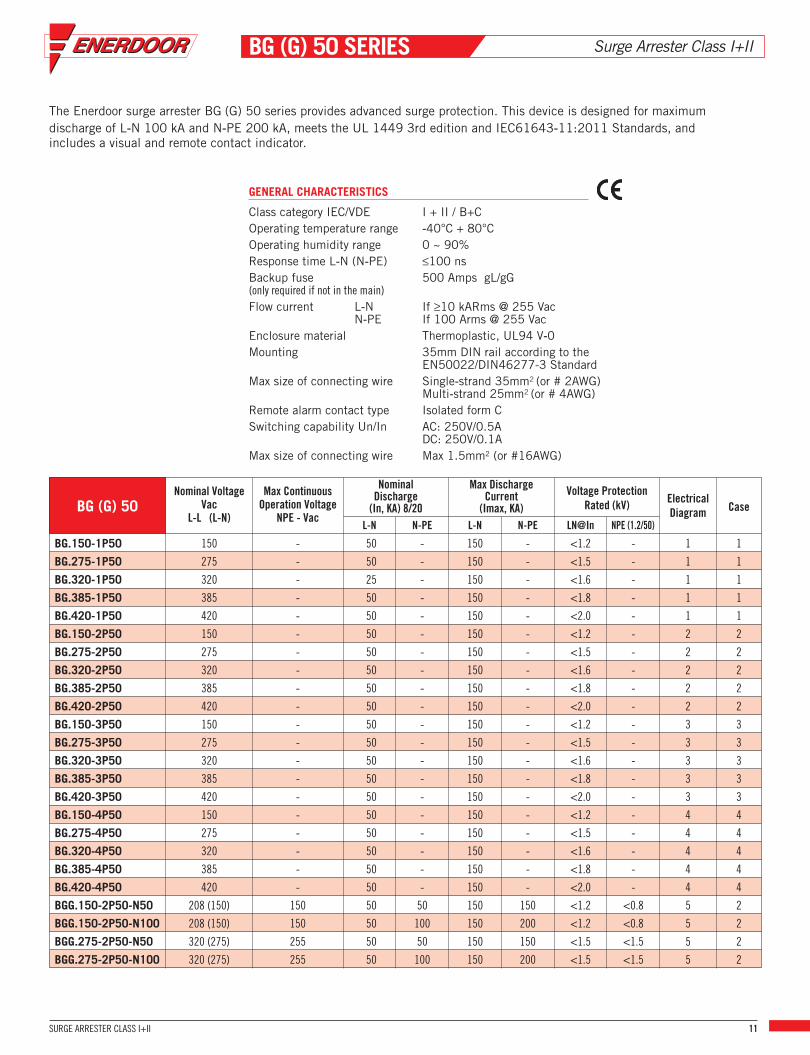
Surge Arrester Class I+IIBG (G) 50 SERIES
The Enerdoor surge arrester BG (G) 50 series provides advanced surge protection. This device is designed for maximumdischarge of L‐N 100 kA and N‐PE 200 kA, meets the UL 1449 3rd edition and IEC61643‐11:2011 Standards, andincludes a visual and remote contact indicator.
Nominal VoltageVac
L-L (L-N)
Max ContinuousOperation Voltage
NPE - Vac
NominalDischarge(In, KA) 8/20
Max DischargeCurrent(Imax, KA)
L-N N-PE L-N N-PE LN@In NPE (1.2/50)
ElectricalDiagram
Voltage ProtectionRated (kV) Case
BG.150-1P50 150 - 50 - 150 - <1.2 - 1 1
BG.275-1P50 275 - 50 - 150 - <1.5 - 1 1
BG.320-1P50 320 - 25 - 150 - <1.6 - 1 1
BG.385-1P50 385 - 50 - 150 - <1.8 - 1 1
BG.420-1P50 420 - 50 - 150 - <2.0 - 1 1
BG.150-2P50 150 - 50 - 150 - <1.2 - 2 2
BG.275-2P50 275 - 50 - 150 - <1.5 - 2 2
BG.320-2P50 320 - 50 - 150 - <1.6 - 2 2
BG.385-2P50 385 - 50 - 150 - <1.8 - 2 2
BG.420-2P50 420 - 50 - 150 - <2.0 - 2 2
BG.150-3P50 150 - 50 - 150 - <1.2 - 3 3
BG.275-3P50 275 - 50 - 150 - <1.5 - 3 3
BG.320-3P50 320 - 50 - 150 - <1.6 - 3 3
BG.385-3P50 385 - 50 - 150 - <1.8 - 3 3
BG.420-3P50 420 - 50 - 150 - <2.0 - 3 3
BG.150-4P50 150 - 50 - 150 - <1.2 - 4 4
BG.275-4P50 275 - 50 - 150 - <1.5 - 4 4
BG.320-4P50 320 - 50 - 150 - <1.6 - 4 4
BG.385-4P50 385 - 50 - 150 - <1.8 - 4 4
BG.420-4P50 420 - 50 - 150 - <2.0 - 4 4
BGG.150-2P50-N50 208 (150) 150 50 50 150 150 <1.2 <0.8 5 2
BGG.150-2P50-N100 208 (150) 150 50 100 150 200 <1.2 <0.8 5 2
BGG.275-2P50-N50 320 (275) 255 50 50 150 150 <1.5 <1.5 5 2
BGG.275-2P50-N100 320 (275) 255 50 100 150 200 <1.5 <1.5 5 2
GENERAL CHARACTERISTICS
Class category IEC/VDE I + II / B+COperating temperature range ‐40°C + 80°COperating humidity range 0 ~ 90%Response time L‐N (N‐PE) ≤100 nsBackup fuse 500 Amps gL/gG(only required if not in the main)Flow current L‐N If ≥10 kARms @ 255 Vac
N‐PE If 100 Arms @ 255 VacEnclosure material Thermoplastic, UL94 V‐0Mounting 35mm DIN rail according to the
EN50022/DIN46277-3 StandardMax size of connecting wire Single‐strand 35mm2 (or # 2AWG)
Multi‐strand 25mm2 (or # 4AWG)Remote alarm contact type Isolated form CSwitching capability Un/In AC: 250V/0.5A
DC: 250V/0.1AMax size of connecting wire Max 1.5mm2 (or #16AWG)
SURGE ARRESTER CLASS I+II 11

Surge Arrester Class I+IIBG (G) 50 SERIES
SCHEMATIC 1 SCHEMATIC 2 SCHEMATIC 3
ELECTRICAL DIAGRAM
SCHEMATIC 4 SCHEMATIC 5 SCHEMATIC 6
MECHANICAL DIMENSIONS (mm)
CASE 1 CASE 2 CASE 3 CASE 4
BG (G) 50Nominal Voltage
VacL-L (L-N)
Max ContinuousOperation Voltage
NPE - Vac
NominalDischarge(In, KA) 8/20
Max DischargeCurrent(Imax, KA)
L-N N-PE L-N N-PE LN@In NPE (1.2/50)
ElectricalDiagram
Voltage ProtectionRated (kV) Case
BGG.320-2P50-N50 400 (320) 255 50 50 150 150 <1.6 <1.5 5 2
BGG.320-2P50-N100 400 (320) 255 50 100 150 200 <1.6 <1.5 5 2
BGG.385-2P50-N50 480 (385) 255 50 50 150 150 <1.8 <1.5 5 2
BGG.385-2P50-N100 480 (385) 255 50 100 150 200 <1.8 <1.5 5 2
BGG.420-2P50-N50 600 (420) 255 50 50 150 150 <2.0 <1.5 5 2
BGG.420-2P50-N100 600 (420) 255 50 100 150 200 <2.0 <1.5 5 2
BGG.150-3P50-N50 208 (150) 255 50 50 150 150 <1.2 <0.8 6 4
BGG.150-3P50-N100 208 (150) 255 50 100 150 200 <1.2 <0.8 6 4
BGG.275-3P50-N50 320 (275) 255 50 50 150 150 <1.5 <1.5 6 4
BGG.275-3P50-N100 320 (275) 255 50 100 150 200 <1.5 <1.5 6 4
BGG.320-3P50-N50 400 (320) 255 50 50 150 150 <1.6 <1.5 6 4
BGG.320-3P50-N100 400 (320) 255 50 100 150 200 <1.6 <1.5 6 4
BGG.385-3P50-N50 480 (385) 255 50 50 150 150 <1.8 <1.5 6 4
BGG.385-3P50-N100 480 (385) 255 50 100 150 200 <1.8 <1.5 6 4
BGG.420-3P50-N50 600 (420) 255 50 50 150 150 <2.0 <1.5 6 4
BGG.420-3P50-N100 600 (420) 255 50 100 150 200 <2.0 <1.5 6 4
12 SURGE ARRESTER CLASS I+II

FINPR
Surge Arrester Class IIFINPR SERIES
The Enerdoor surge arrester FINPR series provides advanced surge protection. This device is designed for maximum discharge of50 kA, meets the UL 1449 3rd edition and IEC61643‐11:2011 Standards, and includes a visual and remote contact indicator.
GENERAL CHARACTERISTICS
Class category IEC/VDE II / COperating temperature range ‐40°C + 80°COperating humidity range 0 ~ 90%Response time ≤25 nsBackup fuse 125 Amps gL/gG(only required if not in the main)Enclosure material Thermoplastic, UL94 V‐0Mounting 35mm DIN rail according to the
EN50022/DIN46277-3 StandardMax size of connecting wire Single‐strand 35mm2 (or # 2AWG)
Multi‐strand 25mm2 (or # 4AWG)Remote alarm contact type Isolated form CSwitching capability Un/In AC: 250V/0.5A
DC: 250V/0.1AMax size of connecting wire Max 1.5mm2 (or #16AWG)
NominalVoltageAC
Nominal Discharge(In, KA) 8/20
Max DischargeCurrent(Imax, KA)
@In @VPR L-N@MLV N-PE@MLV [email protected]/50L-N N-PE L-N N-P
Voltage Protection Rated (kV) SCCR(kA)
ElectricalDiagram
MechanicalCase
PR.150 150 20 20 50 50 <0.8 <0.6 <1.7 - - 200 1 1
PR.275 275 20 20 50 50 <1.4 <0.9 <2.1 - - 200 1 1
PR.320 320 20 20 50 50 <1.5 <1.0 <2.2 - - 200 1 1
PR.420 420 20 20 50 50 <2 <1.5 <2.4 - - 200 1 1
PR.550 550 20 20 50 50 <2.5 <1.8 <2.5 - - 200 1 1
PR.690 690 20 20 50 50 <3 <2.8 <3.2 - - 200 1 1
PR.150-2P 150 20 20 50 50 <0.8 <0.6 <1.7 - - 200 2 2
PR.275-2P 275 20 20 50 50 <1.4 <0.9 <2.1 - - 200 2 2
PR.320-2P 320 20 20 50 50 <1.5 <1.0 <2.2 - - 200 2 2
PR.420-2P 420 20 20 50 50 <2 <1.5 <2.4 - - 200 2 2
PR.550-2P 550 20 20 50 50 <2.5 <1.8 <2.5 - - 200 2 2
PR.690-2P 690 20 20 50 50 <3 <2.8 <3.2 - - 200 2 2
PR.150-3P 150 20 20 50 50 <0.8 <0.6 <1.7 - - 200 3 3
PR.275-3P 275 20 20 50 50 <1.4 <0.9 <2.1 - - 200 3 3
PR.320-3P 320 20 20 50 50 <1.5 <1.0 <2.2 - - 200 3 3
PR.420-3P 420 20 20 50 50 <2 <1.5 <2.4 - - 200 3 3
PR.550-3P 550 20 20 50 50 <2.5 <1.8 <2.5 - - 200 3 3
PR.690-3P 690 20 20 50 50 <3 <2.8 <3.2 - - 200 3 3
PR.150-4P 150 20 20 50 50 <0.8 <0.6 <1.7 - - 200 4 4
PR.275-4P 275 20 20 50 50 <1.4 <0.9 <2.1 - - 200 4 4
PR.320-4P 320 20 20 50 50 <1.5 <1.0 <2.2 - - 200 4 4
PR.420-4P 420 20 20 50 50 <2 <1.5 <2.4 - - 200 4 4
PR.550-4P 550 20 20 50 50 <2.5 <1.8 <2.5 - - 200 4 4
PR.690-4P 690 20 20 50 50 <3 <2.8 <3.2 - - 200 4 4
SURGE ARRESTER CLASS II 13

SCHEMATIC 1 SCHEMATIC 2 SCHEMATIC 3
MECHANICAL DIMENSIONS (mm)
ELECTRICAL DIAGRAM
SCHEMATIC 4 SCHEMATIC 5 SCHEMATIC 6
CASE 1 CASE 2 CASE 3 CASE 4
Surge Arrester Class IIFINPR SERIES
FINPRNominalVoltageVac
L-L (L-N)
Nominal Discharge(In, KA) 8/20
Max DischargeCurrent(Imax, KA)
@In @VPR L-N@MLV N-PE@MLV [email protected]/50L-N N-PE L-N N-P
Voltage Protection Rated (kV) SCCR(kA)
ElectricalDiagram
MechanicalCase
PR.150-PN 208 (150) 20 20 50 50 <0.8 <0.6 <1.7 <1.2 <1.5 200 5 2
PR.275-PN 320 (275) 20 20 50 50 <1.4 <0.9 <2.1 <1.7 <1.5 200 5 2
PR.320-PN 400 (320) 20 20 50 50 <1.5 <1.0 <2.2 <1.7 <1.5 200 5 2
PR.385-PN 480 (385) 20 20 50 50 <2 <1.5 <2.4 <1.7 <1.5 200 5 2
PR.420-PN 600 (420) 20 20 50 50 <2.5 <1.8 <2.5 <1.7 <1.5 200 5 2
PR.150-3PN 208 (150) 20 20 50 50 <0.8 <0.6 <1.7 <1.2 <1.5 200 6 4
PR.275-3PN 320 (275) 20 20 50 50 <1.4 <0.9 <2.1 <1.7 <1.5 200 6 4
PR.320-3PN 400 (320) 20 20 50 50 <1.5 <1.0 <2.2 <1.7 <1.5 200 6 4
PR.385-3PN 480 (385) 20 20 50 50 <2 <1.5 <2.4 <1.7 <1.5 200 6 4
PR.420-3PN 600 (420) 20 20 50 50 <2.5 <1.8 <2.5 <1.7 <1.5 200 6 4
14 SURGE ARRESTER CLASS II

Surge Arrester Class II+IIIEMG (G) 20 SERIES
The Enerdoor surge arrester EMG (G) 20 series provides advanced surge protection. This device is designed for maximumdischarge of 40 kA, meets the UL 1449 3rd edition and IEC61643-11:2011 Standards, and includes a visual and remotecontact indicator.
GENERAL CHARACTERISTICS
Class category IEC/VDE II+III / C+DOperating temperature range -40°C + 80°COperating humidity range 0 ~ 90%Response time ≤100 nsBackup fuse 125 Amps gL/gG(only required if not in the main)Enclosure material Thermoplastic, UL94 V-0Mounting 35mm DIN rail according to the
EN50022/DIN46277-3 StandardMax size of connecting wire Single-strand 35mm2 (or # 2AWG)
Multi-strand 25mm2 (or # 4AWG)Remote alarm contact type Isolated form CSwitching capability Un/In AC: 250V/0.5A
DC: 250V/0.1AMax size of connecting wire Max 1.5mm2 (or #16AWG)
EMG (G) 20NominalVoltageVac
L-L (L-N)
Nominal Discharge(In, KA) 8/20
Max Discharge Current(Imax, KA)
@In @VPR N-PE (1.2/50)L-N N-PE L-N N-PE
Voltage Protection Rated (kV)Case
EMG.150-1P20 150 20 - 40 - <0.6 <0.5 - 1
EMG.275-1P20 275 20 - 40 - <1.2 <0.8 - 1
EMG.320-1P20 320 20 - 40 - <1.3 <0.9 - 1
EMG.420-1P20 420 20 - 40 - <1.6 <1.1 - 1
EMG.150-3P20 150 20 - 40 - <0.6 <0.5 - 2
EMG.275-3P20 275 20 - 40 - <1.2 <0.8 - 2
EMG.320-3P20 320 20 - 40 - <1.3 <0.9 - 2
EMG.420-3P20 420 20 - 40 - <1.6 <1.1 - 2
EMG.150-4P20 150 20 - 40 - <0.6 <0.5 - 3
EMG.275-4P20 275 20 - 40 - <1.2 <0.8 - 3
EMG.320-4P20 320 20 - 40 - <1.3 <0.9 - 3
EMG.420-4P20 420 20 - 40 - <1.6 <1.1 - 3
EMGG.150-3P20N20 208 (150) 20 20 40 40 <0.6 <0.5 <0.8 4
EMGG.275-3P20N20 320 (275) 20 20 40 40 <1.2 <0.8 <1.5 4
EMGG.320-3P20N20 400 (320) 20 20 40 40 <1.3 <0.9 <1.5 4
EMGG.420-3P20N20 600 (420) 20 20 40 40 <1.6 <1.1 <1.5 4
SURGE ARRESTER CLASS II+III 15

Surge Arrester Class II+IIIEMG (G) 20 SERIES
MECHANICAL DIMENSIONS (mm)
CASE 1 CASE 2 CASE 3 CASE 4
SCHEMATIC 1 SCHEMATIC 2 SCHEMATIC 3
ELECTRICAL DIAGRAM
SCHEMATIC 4
16 SURGE ARRESTER CLASS II+III

Surge Arrester Class II+IIIEMG (G) 40 SERIES
The Enerdoor surge arrester EMG (G) 40 series provides advanced surge protection. This device is designed for maximumdischarge of 80 kA, meets the UL 1449 3rd edition and IEC61643-11:2011 Standards, and includes a visual and remotecontact indicator.
GENERAL CHARACTERISTICS
Class category IEC/VDE II+III / C+DOperating temperature range -40°C + 80°COperating humidity range 0 ~ 90%Response time ≤100 nsBackup fuse 200 Amps gL/gG(only required if not in the main)Enclosure material Thermoplastic, UL94 V-0Mounting 35mm DIN rail according to the
EN50022/DIN46277-3 StandardMax size of connecting wire Single-strand 35mm2 (or # 2AWG)
Multi-strand 25mm2 (or # 4AWG)Remote alarm contact type Isolated form CSwitching capability Un/In AC: 250V/0.5A
DC: 250V/0.1AMax size of connecting wire Max 1.5mm2 (or #16AWG)
EMG (G) 40NominalVoltageVac
L-L (L-N)
Nominal Discharge(In, KA) 8/20
Max Discharge Current(Imax, KA)
@In @VPR N-PE (1.2/50)L-N N-PE L-N N-PE
Voltage Protection Rated (kV)Case
EMG.150-1P40 150 40 - 80 - <0.6 <0.5 - 1
EMG.275-1P40 275 40 - 80 - <1.2 <0.8 - 1
EMG.320-1P40 320 40 - 80 - <1.3 <0.9 - 1
EMG.420-1P40 420 40 - 80 - <1.6 <1.1 - 1
EMG.150-3P40 150 40 - 80 - <0.6 <0.5 - 2
EMG.275-3P40 275 40 - 80 - <1.2 <0.8 - 2
EMG.320-3P40 320 40 - 80 - <1.3 <0.9 - 2
EMG.420-3P40 420 40 - 80 - <1.6 <1.1 - 2
EMG.150-4P40 150 40 - 80 - <0.6 <0.5 - 3
EMG.275-4P40 275 40 - 80 - <1.2 <0.8 - 3
EMG.320-4P40 320 40 - 80 - <1.3 <0.9 - 3
EMG.420-4P40 420 40 - 80 - <1.6 <1.1 - 3
EMGG.150-3P40N40 208 (150) 40 40 80 80 <0.6 <0.5 <0.8 4
EMGG.275-3P40N40 320 (275) 20 40 80 80 <1.2 <0.8 <1.5 4
EMGG.320-3P40N40 400 (320) 40 40 80 80 <1.3 <0.9 <1.5 4
EMGG.420-3P40N40 600 (420) 40 40 80 80 <1.6 <1.1 <1.5 4
SURGE ARRESTER CLASS II+III 17

Surge Arrester Class II+IIIEMG (G) 40 SERIES
MECHANICAL DIMENSIONS (mm)
CASE 1 CASE 2 CASE 3 CASE 4
SCHEMATIC 1 SCHEMATIC 2 SCHEMATIC 3
ELECTRICAL DIAGRAM
SCHEMATIC 4
18 SURGE ARRESTER CLASS II+III

Surge Arrester Class II+IIIEMG (G) 60 SERIES
The Enerdoor surge arrester EMG (G) 60 series provides advanced surge protection. This device is designed for maximumdischarge of 120 kA, meets the UL 1449 3rd edition and IEC61643-11:2011 Standards, and includes a visual and remotecontact indicator.
GENERAL CHARACTERISTICS
Class category IEC/VDE II+III / C+DOperating temperature range -40°C + 80°COperating humidity range 0 ~ 90%Response time ≤100 nsBackup fuse 315 Amps gL/gG(only required if not in the main)Enclosure material Thermoplastic, UL94 V-0Mounting 35mm DIN rail according to the
EN50022/DIN46277-3 StandardMax size of connecting wire Single-strand 35mm2 (or # 2AWG)
Multi-strand 25mm2 (or # 4AWG)Remote alarm contact type Isolated form CSwitching capability Un/In AC: 250V/0.5A
DC: 250V/0.1AMax size of connecting wire Max 1.5mm2 (or #16AWG)
EMG (G) 60NominalVoltageVac
L-L (L-N)
Nominal Discharge(In, KA) 8/20
Max Discharge Current(Imax, KA)
@In @VPR N-PE (1.2/50)L-N N-PE L-N N-PE
Voltage Protection Rated (kV)Case
EMG.150-1P60 150 60 - 120 - <0.6 <0.5 - 1
EMG.275-1P60 275 60 - 120 - <1.2 <0.8 - 1
EMG.320-1P60 320 60 - 120 - <1.3 <0.9 - 1
EMG.420-1P60 420 60 - 120 - <1.6 <1.1 - 1
EMG.150-3P60 150 60 - 120 - <0.6 <0.5 - 2
EMG.275-3P60 275 60 - 120 - <1.2 <0.8 - 2
EMG.320-3P60 320 60 - 120 - <1.3 <0.9 - 2
EMG.420-3P60 420 60 - 120 - <1.6 <1.1 - 2
EMG.150-4P60 150 60 - 120 - <0.6 <0.5 - 3
EMG.275-4P60 275 60 - 120 - <1.2 <0.8 - 3
EMG.320-4P60 320 60 - 120 - <1.3 <0.9 - 3
EMG.420-4P60 420 60 - 120 - <1.6 <1.1 - 3
EMGG.150-3P60N60 208 (150) 60 60 120 120 <0.6 <0.5 <0.8 4
EMGG.275-3P60N60 320 (275) 60 60 120 120 <1.2 <0.8 <1.5 4
EMGG.320-3P60N60 400 (320) 60 60 120 120 <1.3 <0.9 <1.5 4
EMGG.420-3P60N60 600 (420) 60 60 120 120 <1.6 <1.1 <1.5 4
SURGE ARRESTER CLASS II+III 19

Surge Arrester Class II+IIIEMG (G) 60 SERIES
MECHANICAL DIMENSIONS (mm)
CASE 1 CASE 2 CASE 3 CASE 4
SCHEMATIC 1 SCHEMATIC 2 SCHEMATIC 3
ELECTRICAL DIAGRAM
SCHEMATIC 4
20 SURGE ARRESTER CLASS II+III

Surge Arrester Class IIFINPRS SERIES
The Enerdoor surge arrester FINPRS series provides advanced surge protection for common mode and common mode + differential mode DC surge. This device is designed for maximum discharge of 50 kA, meets the UL 1449 3rd edition andIEC61643‐11:2011 Standards, and includes a visual and remote contact indicator.
FINPRSNominalVoltageVdc
MaxContinuosOperating
Vdc
NominalDischarge(In, KA) 8/20
MaxDischargeCurrent
@In @VPR L-N@MLVL-N L-N Electrical Mechanical
Voltage Protection Rated (kV) Case
GENERAL CHARACTERISTICS
Class category IEC/VDE II / COperating temperature range ‐40°C + 80°COperating humidity range 0 ~ 90%Response time L‐N ≤25 nsBackup fuse 125 Amps gR/gPV(only required if not in the main)Enclosure material Thermoplastic, UL94 V‐0Mounting 35mm DIN rail according to the
EN50022/DIN46277-3 StandardMax size of connecting wire Single‐strand 35mm2 (or # 2AWG)
Multi‐strand 25mm2 (or # 4AWG)Remote alarm contact type Isolated form CSwitching capability Un/In AC: 250V/0.5A
DC: 250V/0.1AMax size of connecting wire Max 1.5mm2 (or #16AWG)
.500-M-CS 500 550 20 50 <2.0 <1.5 <2.4 1 1
.600-M-CS 600 745 20 50 <2.5 <1.8 <2.8 1 1
.600-M-CDS 600 700 20 50 <2.8 <1.8 <4.2 2 2
.750-M-CDS 750 840 20 50 <3.0 <2.0 <4.4 2 2
.1000-M-CDS 1000 1120 20 50 <4.0 <3.0 <4.8 2 2
.1200-M-CDS 1200 1490 20 50 <5.0 <3.6 <5.6 2 2
SURGE ARRESTER CLASS II 21

SCHEMATIC 1 SCHEMATIC 2
MECHANICAL DIMENSIONS (mm)
ELECTRICAL DIAGRAM
CASE 1 CASE 2
Surge Arrester Class IIFINPRS SERIES
22 SURGE ARRESTER CLASS II

Voltage Stabilizers
Transformers andLine Reactors
RFI Filters
Passive and ActiveHarmonic Filters
Motor Protection

USAENERDOOR Inc
Toll Free 1-877-778-2875Phone 1-207-210-6511Fax [email protected]
GERMANYENERDOOR Gmbh
Phone +49 (0) 6642 223692Fax +49 (0) 6642 223558
SWITZERLANDENERDOOR SA
Phone +41 (0) 91 9228060Fax +41 (0) 91 9228061
ITALYFINMOTOR Srl
Phone +39 02 4891 0020Fax +39 02 4891 [email protected]
HUNGARYEICHHOFF ELEKTRO KftPhone +36 27 511180Fax +36 27 511187
10-2
015