surveillance of modern gasoline – engines and catalyst behavior
TRANSCRIPT

International Technical Sciences Journal (ITSJ) June 2014 edition Vol.1, No.1
10
SURVEILLANCE OF MODERN GASOLINE – ENGINES AND CATALYST BEHAVIOR
Periklis G. Chasiotis, Associate Prof. Technological Educational Institute (TEI) of Thessaly, Greece
Panagiotis E. Paroutis Graduate Technological Educational Institute (TEI) of Thessaly, Greece
Abstract In the last two decades an integral and continuous development of the two most important engine systems, i.e. the mixture preparation system and the ignition system, was achieved. This development is due to several factors such as to minimize the exhaust emissions, to reduce the fuel consumption, to increase the intervals between successive engine services, and to insure an easy motor operation into these intervals. Furthermore, a significant improvement of the driving system in order to better drivability and regular car kinematic was obtained. Therefore, a full diagnosis of the operation condition of all new engine systems isnecessary to prevent their possible malfunction or to restore them in the case of damages. In the course of modern engines diagnosis, measurements were taken on a Matiz Daewoo car which belongs to the Internal Combustion Engines laboratory of the Dept. of Mechanical Engineering TE, TEI of Thessaly, by using of an appropriate control program. The influence of transient load condition to the catalyst behavior also was studied and the response of the λ-sensors signals was explained.
Keywords: Gasoline, engines HISTORICAL The application and the evolution of the On Board Diagnosis system (OBD) is due to the so called main USA Organizations :
a. The California Air Resourse Board – CARB and b. The California Air Protection Agency – CAL EPA
The CAL EPA restrictions and his policy enforcement have given the possibility to the CARB to apply air quality programs which were used as a direction for likely legislation in several countries, even the EU. OBD I system has been applied in California since 1988. In accordance to this simple system the mission of the Engine Control Unit
International Technical Sciences Journal (ITSJ) June 2014 edition Vol.1, No.1
11
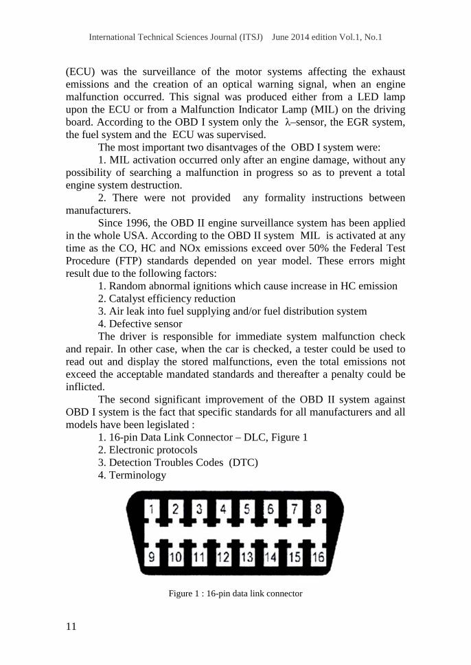
(ECU) was the surveillance of the motor systems affecting the exhaust emissions and the creation of an optical warning signal, when an engine malfunction occurred. This signal was produced either from a LED lamp upon the ECU or from a Malfunction Indicator Lamp (MIL) on the driving board. According to the OBD I system only the λ–sensor, the EGR system, the fuel system and the ECU was supervised. The most important two disantvages of the OBD I system were: 1. MIL activation occurred only after an engine damage, without any possibility of searching a malfunction in progress so as to prevent a total engine system destruction. 2. There were not provided any formality instructions between manufacturers. Since 1996, the OBD II engine surveillance system has been applied in the whole USA. According to the OBD II system MIL is activated at any time as the CO, HC and NOx emissions exceed over 50% the Federal Test Procedure (FTP) standards depended on year model. These errors might result due to the following factors: 1. Random abnormal ignitions which cause increase in HC emission 2. Catalyst efficiency reduction 3. Air leak into fuel supplying and/or fuel distribution system 4. Defective sensor The driver is responsible for immediate system malfunction check and repair. In other case, when the car is checked, a tester could be used to read out and display the stored malfunctions, even the total emissions not exceed the acceptable mandated standards and thereafter a penalty could be inflicted. The second significant improvement of the OBD II system against OBD I system is the fact that specific standards for all manufacturers and all models have been legislated : 1. 16-pin Data Link Connector – DLC, Figure 1 2. Electronic protocols 3. Detection Troubles Codes (DTC) 4. Terminology
Figure 1 : 16-pin data link connector
International Technical Sciences Journal (ITSJ) June 2014 edition Vol.1, No.1
12
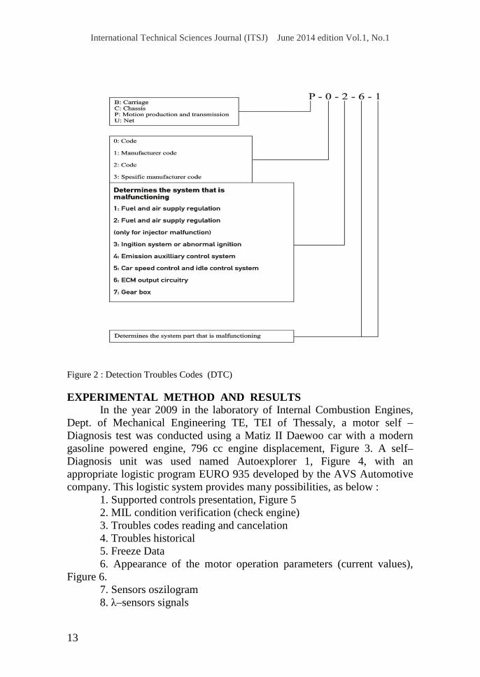
The OBD II Diagnosis system also includes a truly most unfolded management system improved up today. This logistic comprises : 1. Two lambda oxygen sensors (λ–sensor), usually heated, upstream and downstream of the catalytic converter (HO2S). 2. More powerfull Electronic Control Module (ECM) with Electronic Erased Programmized Read Only Memory (EEPROM) which permits the ECM to be reprogrammized with the latest logistic improvement. 3. Evaporative emissions control system with activated charcoal filter. 4. Exhaust Gas Recirculation system (EGR). 5. Serial fuel injection system instead of the Multi–Point Injection system (MPI) or the Mono–Jetronic system. 6. Manifold Absolute Pressure sensor (MAP) and Mass Air Flow sensor (MAF) to engine load monitoring. 7. Cut–off engine operation calculated from throttle valve position, engine speed and cool water temperature. Since June 1994, SAE has published the J1978 «OBD II Diagnosis» direction and since July 1996 the J1979 «Diagnosis Control Operations» direction. So, three main protocols have been formed : a. The Chrysler models, all european models and the most of asiatic models use the ISO 9141 communication wiring. b. All cars and light–duty trucks of General Motors use Variable Pulse Wide (VPW) communication form according to the SAE J1850 direction. c. All Ford cars use the so named Pulse Wide Modification (PWM) communication form in accordance to the SAE J1850 direction. The Detection Troubles Codes (DTC) are formulated according to the SAE J2012 direction. These codes consist from five (5) symbols, shown in Figure 2. The code P0261, e.g., related to the injector 1 damage – low pressure circuitry. Since 2000, the OBD II Diagnosis engine management is obligatory applied to all European vehicles.
International Technical Sciences Journal (ITSJ) June 2014 edition Vol.1, No.1
13
Figure 2 : Detection Troubles Codes (DTC) EXPERIMENTAL METHOD AND RESULTS In the year 2009 in the laboratory of Internal Combustion Engines, Dept. of Mechanical Engineering TE, TEI of Thessaly, a motor self – Diagnosis test was conducted using a Matiz II Daewoo car with a modern gasoline powered engine, 796 cc engine displacement, Figure 3. A self–Diagnosis unit was used named Autoexplorer 1, Figure 4, with an appropriate logistic program EURO 935 developed by the AVS Automotive company. This logistic system provides many possibilities, as below : 1. Supported controls presentation, Figure 5 2. MIL condition verification (check engine) 3. Troubles codes reading and cancelation 4. Troubles historical 5. Freeze Data 6. Appearance of the motor operation parameters (current values), Figure 6. 7. Sensors oszilogram 8. λ–sensors signals

International Technical Sciences Journal (ITSJ) June 2014 edition Vol.1, No.1
14
Figure 3 : The Matiz II Daewoo motor
Figure 4 :Motor self – Diagnosis unit Autoexplorer 1 with 16–pin data link connector

International Technical Sciences Journal (ITSJ) June 2014 edition Vol.1, No.1
15
Figure 5 : Supported controls by the EURO 935 motor self–Diagnosis program
Figure 6 : Current values of motor operation parameters

International Technical Sciences Journal (ITSJ) June 2014 edition Vol.1, No.1
16
Figure 7 shows the voltage variation of the two oxygen sensors at engine speed 965 rpm (idle). The voltage of the first oxygen sensor upstream of the catalytic converter (green color) goes continuously up and down, between two limited values, this means that a permanent correction of the injected fuel quantity is obtained which results to a maintained stoichiometric air–fuel mixture and therefore a full potential performance of the catalytic converter is achieved. The voltageof the second oxygen sensor downstream of the catalytic converter (blue color) remains constant. This means that the catalyst operates at the highest efficiency so that the oxygen concentration after the catalyst is constant.
Figure 7 : Voltage variation of the two oxygen sensors at idle
Figure 8 shows the corresponding voltage variation when the motor
operates at increased idle (2218 rpm). The voltage drop of the second oxygen sensor downstream of the catalyst (blue color) is due to the fact that at the same time the catalyst reaches its correct operative temperature.
International Technical Sciences Journal (ITSJ) June 2014 edition Vol.1, No.1
17
Figure 8 : Voltage variation of the two oxygen sensors at increased idle
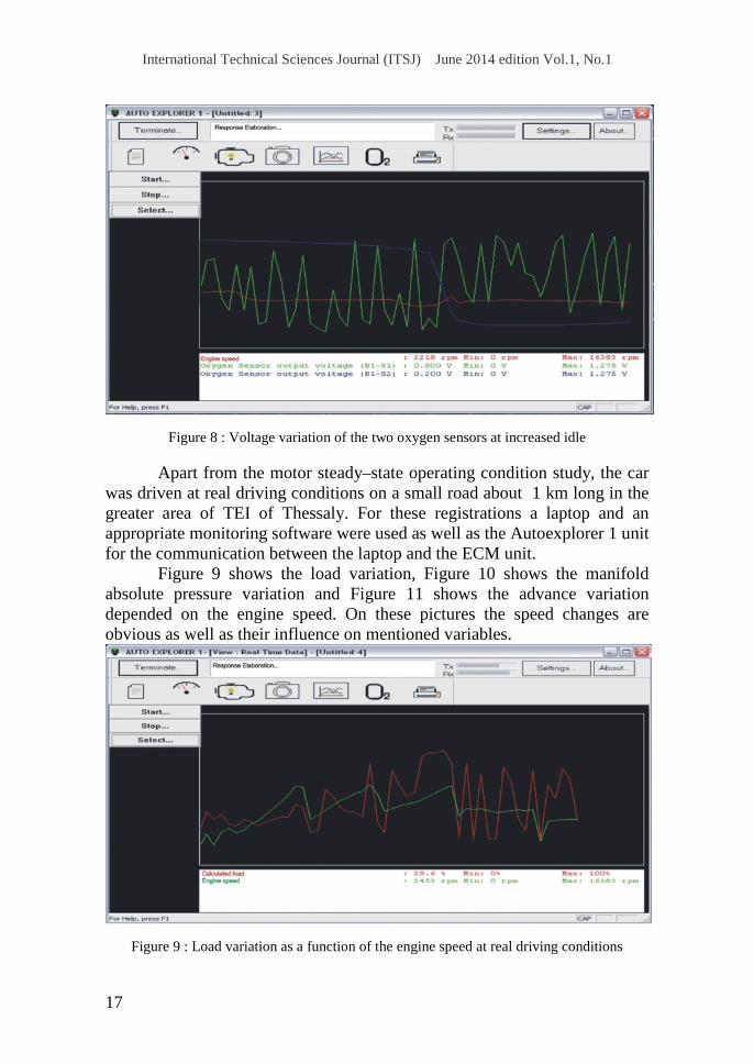
Apart from the motor steady–state operating condition study, the car
was driven at real driving conditions on a small road about 1 km long in the greater area of TEI of Thessaly. For these registrations a laptop and an appropriate monitoring software were used as well as the Autoexplorer 1 unit for the communication between the laptop and the ECM unit.
Figure 9 shows the load variation, Figure 10 shows the manifold absolute pressure variation and Figure 11 shows the advance variation depended on the engine speed. On these pictures the speed changes are obvious as well as their influence on mentioned variables.
Figure 9 : Load variation as a function of the engine speed at real driving conditions

International Technical Sciences Journal (ITSJ) June 2014 edition Vol.1, No.1
18
Figure 10 : Manifold absolute pressure variation as a function of the engine speed at real
driving conditions
Figure 11 : Advance variation as a function of the engine speed at real driving conditions
Figure 12 shows the voltage variation of the two oxygen sensors in
accordance to the engine speed. The voltage of the first oxygen sensor upstream of the catalyst (green color) goes continuously up and down for the permanent correction of the injected fuel. The voltage of the second oxygen sensor downstream of the catalyst (blue color) remains constant at the lower engine speed, because it corresponds to the constant oxygen

International Technical Sciences Journal (ITSJ) June 2014 edition Vol.1, No.1
19
concentration of the exhaust gas (highest catalyst efficiency). However, as the engine speed increases (after the midle of the picture), the second oxygen sensor voltage follows in a parallel course the variation of the voltage of the first oxygen sensor. This fact can be explained as follows :
When the engine speed increases rapidly as the accelerator pedal is suddenly pressed, because of that transient driving phenomenon, the correction of the air–fuel ratio which could be achieved by the first oxygen sensor is not completed and thereafter the conversion factor of the catalyst is not sufficiently effective. At such cases even the second oxygen sensor itself produces a different voltage signal, just as it tries to correct the remained oxygen concentration in the exhaust gas into the control volume of the catalyst, due to the variation of the mixture stoichiometric caused by the transient motor load situation. This fluctuation of the voltage signal of the second oxygen sensor occurs even during the cold motor operation.
Figure 12 : Voltage variation of the two oxygen sensors at transient driving condition
CONCLUSION 1. OBD II is an absolute reliable car surveillance method to search possible malfunctions and/or damages of all modern engine systems. 2. Not only the operating condition of isolated sensors, but also many motor operation parameters can be checked.
International Technical Sciences Journal (ITSJ) June 2014 edition Vol.1, No.1
20
3. The catalytic converter efficiency can be easily determined and the catalyst behavior at transient load condition can be studied and explained, as well. 4. By using the OBD III telemetry method, motor system malfunctions or high emission problems occurred in a car can be immediately transmitted to a supervising administration so that only these cars would be taken for inspection and repairing. 5. In the future, a so called «’fly by wire» acceleration pedal control system with electric wire can be applied to prevent abnormal ignitions in the next car generation with extreme low emissions. References: 1. Daewoo Matiz manufacturer book 2. Bosch – automotive handbook 3. http://www.16pin.com (AVS Automotive) 4. http://www.telematica.gr/Tech/OBD/Tech.html 5. http://www.obdii.com/ 6. http://www.wikipedia.org/wiki/On-board diagnostics 7. http://www.yme.gr