survey & mapping specifications - pages and... · mapping is assigned an accuracy detail class...
TRANSCRIPT

Survey & Mapping Specifications
Office of CADD & Mapping Services
July 15, 2016

Glossary of Terms .................................................................................................................................................. i
100 Introduction ................................................................................................................................................... 4
101 Purpose ............................................................................................................................................ 4
102 Audiences ......................................................................................................................................... 4
103 Scope of Work .................................................................................................................................. 4
104 Quality Control Report .................................................................................................................... 4
200 Safety ............................................................................................................................................................. 4
201 General ............................................................................................................................................. 4
202 Public Utilities .................................................................................................................................. 4
203 Traffic Control .................................................................................................................................. 4
204 Construction Site Safety .................................................................................................................. 5
205 Confined Space Entry ....................................................................................................................... 5
300 Datum’s, Coordinate Systems, and Positioning Parameters ....................................................................... 5
301 Vertical Positioning .......................................................................................................................... 5
302 Horizontal Positioning ............................................................................................................... 5
400 Units of Measurement .................................................................................................................................. 6
401 Distance ........................................................................................................................................... 6
402 Angles ............................................................................................................................................... 6
403 Direction .......................................................................................................................................... 6
404 Area .................................................................................................................................................. 6
405 Volume ............................................................................................................................................. 6
406 Horizontal Coordinates .................................................................................................................... 6
407 Elevation/Orthometric height ......................................................................................................... 6
500 Types of Surveys ............................................................................................................................................ 6
501 General ............................................................................................................................................. 6
501.1 Property Owner Notification of Entry ............................................................................ 6

502 Control Surveys ................................................................................................................................ 7
502.1 General ............................................................................................................................ 7
502.2 Project Control ................................................................................................................ 7
A. General .................................................................................................................... 7
B. Primary Project Control ......................................................................................... 7
C. Primary Project Control Type ................................................................................. 7
D. Primary Project Control Monuments .................................................................... 8
E. Survey Equipment .................................................................................................. 9
F. Static GNSS Data Collection ................................................................................... 9
G. Static GNSS Data Processing .................................................................................. 9
H. ODOT VRS Data Collection ................................................................................... 10
I. Coordinate Statistical Analysis .............................................................................. 10
J. Primary Project Control Monument Horizontal Coordinates .............................. 11
K. Primary Project Control Monument Vertical Coordinates ................................. 11
L. Secondary and Temporary Project Control .......................................................... 11
M. Project Scale Factor (Grid to Ground multiplier) ............................................... 11
N. Deliverables ......................................................................................................... 12
502.3 Aerial Photo Ground Control................................................................................... 13
A. General ................................................................................................................. 13
B. Aerial Targets ....................................................................................................... 13
C. Picture Points ....................................................................................................... 13
D. Aerial Photo Ground Control Surveys ................................................................. 14
E. Survey Feature Codes ........................................................................................... 14
502.4 Differential Leveling ...................................................................................................... 14
A. General ................................................................................................................. 14
B. Project Benchmarks ............................................................................................. 14
C. Differential Leveling Surveys ............................................................................... 14

D. Closure Requirements ......................................................................................... 14
E. Leveling adjustments ............................................................................................ 15
F. Deliverables .......................................................................................................... 15
503 Boundary Surveys ...................................................................................................................... 15
503.1 General .......................................................................................................................... 15
503.2 Property Surveys ........................................................................................................... 15
503.3 Right of Way & Highway Centerline Surveys ............................................................... 15
504 Mapping Surveys ........................................................................................................................... 16
504.1 General .......................................................................................................................... 16
504.2 Topographic Surveys ..................................................................................................... 16
A. Digital Terrain Model (DTM) ................................................................................ 16
B. Accuracies ............................................................................................................. 16
C. Triangulated Irregular Network (TIN) .................................................................. 16
D. Vertical TIN Accuracy Testing Procedure ............................................................ 17
E. Deliverables .......................................................................................................... 17
504.3 Planimetric Features ..................................................................................................... 18
A. Description ........................................................................................................... 18
B. Accuracy ............................................................................................................... 19
The planimetric accuracy detail classes with the corresponding maximum allowable
RMSE are provided below: ......................................................................................... 19
C. Horizontal Planimetric Feature Accuracy Testing Procedure ............................. 19
D. Orthophoto .......................................................................................................... 20
E. Deliverables .......................................................................................................... 20
504.4 Bridge ............................................................................................................................ 21
504.5 Hydrographic ................................................................................................................. 21
505 Construction .................................................................................................................................. 22
505.1 General .......................................................................................................................... 22

505.2 Construction Staking ..................................................................................................... 22
505.3 Machine Control ........................................................................................................... 22
600 Survey Equipment ....................................................................................................................................... 22
601 Equipment Care and Maintenance ............................................................................................... 22
602 Equipment Types and Specifications ............................................................................................ 22
602.1 Levels ............................................................................................................................. 22
602.2 Total Stations ................................................................................................................ 23
602.3 GNSS Receivers ............................................................................................................. 23
603 Equipment Calibration and Maintenance ..................................................................................... 23
603.1 Levels ............................................................................................................................. 23
603.2 Total Stations ................................................................................................................ 23
603.3 Tripods, Tribrach’s, Prism Rods, and RTK Rods ............................................................ 24
Appendix A –Planimetric Collection .................................................................................................................. 26
Class I Planimetric Features ............................................................................................................ 27
Class II Planimetric Features .......................................................................................................... 29
Appendix B –Example RMSE Calculation for Vertical TIN & Horizontal Planimetric Features ........................ 31
Appendix C –Example Mapping Quality Control Report ................................................................................. 37
Appendix D – Example Static GNSS Coordinate Statistical Analysis ................................................................... 46
Appendix E – Example OPUS Report ................................................................................................................... 48
Appendix F – Surveyor’s Certification Statement ............................................................................................ 50
Appendix G – Property Owner Notification ..................................................................................................... 52
Appendix H – Project Control Monuments ......................................................................................................... 54
Appendix J – L & D Manual G105 Survey Parameters ........................................................................................ 58
Appendix H – Project Scale Factor Calculations .................................................................................................. 60

i
Glossary of Terms
Azimuth Mark: A Type ‘A’ or Type ‘B’ project control monument set at the end points of the project for
use as a ‘backsight’ point.
Benchmark: A relatively permanent object, natural or artificial, bearing a marked point whose elevation
is above or below a referenced datum with a known published elevation.
Check Points: 3-dimensional positions obtained independently of Survey Points by traditional ground
surveying, Real Time Kinematic GNSS surveying or Static GNSS. Check Points are used to verify the
accuracy of the TIN.
Combined Scale Factor: A conversion factor that uses the combination of the Grid Scale factor and the
Elevation Scale Factor of a point to reduce horizontal ground distances to grid distances.
Department: The Department of Transportation, State of Ohio. (ODOT)
DTM Accuracy Class: A specific area within the mapping limits that has an assigned maximum allowable
Dz and RMSE. The number of areas and the DTM accuracy class for each area is assigned by the District
Survey Operations Manager
Dz: Mathematical difference between elevations from the Check Points and elevations produced from the
TIN (created from the Survey Points) at the same horizontal location.
Differential Leveling: Determining the difference in elevation between two points by the sum of
incremental vertical displacements of a graduated rod.
Elevation Scale Factor: A multiplier used to change horizontal ground distances to geodetic (ellipsoid)
distances. Geodetic Datum:
1. “A set of constants specifying the coordinate system used for geodetic control, i.e., for calculating
the coordinates of points on the Earth.”
2. “The datum, as defined in (1), together with the coordinate system and the set of all points and
lines whose coordinates, lengths, and directions have been determined by measurement or
calculation.”
Global Navigation Satellite System (GNSS): Any satellite system which can be used to determine a
precise location on the surface of the Earth. The US system is known as NAVSTAR Global Positioning
System (GPS). The Russian system is known as the Global'naya Navigatsionnaya Sputnikovaya
Sistema or GLONASS. The European Space Agency system is known as GALILEO. The Chinese
government GPS system is known as Beidou.
Grid Scale Factor: A multiplier used to change geodetic distances based on the ellipsoid to the grid plane.
Hydrographic Survey: A survey having for its principal purpose the determination of data relating to
bodies of water, and which may consist of the determination of one or several of the following classes of
data; depth of water and configuration of bottom; directions and force of current; heights, times and water
stages; and location of fixed objects for survey and navigation purposes.

ii
Multipath (Multipath Error): The error that results when a reflected GNSS signal is received. When the
signal reaches the receiver by two or more different paths, the reflected paths are longer and cause incorrect
pseudo ranges or carrier phase measurements and subsequent positioning errors. Multipath is mitigated
with various preventive antenna designs and filtering algorithms.
OPUS Static: The National Geodetic Survey’s On-Line Positioning User Service (OPUS). OPUS accepts
a user’s GPS tracking data and uses corresponding data from the U.S. Continuously Operating Reference
Station (CORS) Network to compute 3 dimensional positional coordinates of the user’s submitted data.
OPUS processes a 3 dimensional coordinate with an accuracy of a few centimeters for data sets spanning 2
hours or more.
OPUS-RS: A rapid static form of the National Geodetic Survey’s On-Line Positioning User Service
(OPUS). OPUS-RS accepts a user’s GPS tracking data and uses corresponding data from the U.S.
Continuously Operating Reference Station (CORS) Network to compute 3 dimensional positional
coordinates of the user’s submitted data. OPUS-RS can process a 3 dimensional coordinate with an
accuracy of a few centimeters for data sets spanning as little as 15 minutes.
Planimetric Features: Existing 2-dimensional features collected with traditional ground surveying,
Real Time Kinematic GNSS surveying, or Photogrammetry for use in engineering projects (example:
existing pavement edge line).
Planimetric Check Points: 2-dimensional positions that are obtained independently of the planimetric
feature data collection. Use traditional ground surveying or Real Time Kinematic GNSS surveying.
Planimetric Accuracy Detail Class: The required amount of detailed features to be collected. The
mapping is assigned an accuracy detail class by the District Survey Operations Manager.
Project Benchmark: A vertical position transferred from a primary project control monument for use on
a specific project.
Project Development Process (PDP): The process used by The Ohio Department of Transportation to
develop and manage construction projects. ODOT projects are categorized by 5 Paths, Path 1 being the
simplest ODOT project to Path 4 and Path 5 being ODOT’s most complex projects.
Project Scale Factor: The inverse of the Combined Scale factor (1/Combined Scale Factor) used to
convert grid distances and coordinates to ground distances and coordinates.
Position Dilution of Precision (PDOP): A numerical representation of the predicted accuracy of a
geodetic position determined from GNSS satellites. The term represents the quality of the satellite
geometry with respect to the receiver location. A PDOP of 3 or less will generally insure accuracy of the
highest survey quality.
Real Time Kinematic (RTK) GNSS Survey: A method of determining relative positions between known
control and unknown positions using carrier phase measurements. A base station at the known point
transmits corrections to the roving receiver offering high accuracy positions in real time.
Right of Way Survey: A survey performed for the purpose of laying out an acceptable route for an
easement or right of way for a road, pipeline, utility, or transmission line. This survey would include the
establishment of all boundary lines and road crossings along the route.

iii
Root Mean Square Error (RMSE): Mathematical calculation that is used to describe the vertical
mapping accuracy encompassing both random and systematic errors.
Static GNSS Survey: A geodetic survey that uses survey grade satellite receivers to collect satellite data
on a fixed point requiring post processing to determine position.
Survey Points: 3-dimensional positions collected with traditional ground surveying, Real Time
Kinematic GNSS surveying, Static GNSS, Photogrammetry, or Light Detection and Ranging (LiDAR).
Survey Points are used to create the Triangulated Irregular Network (TIN).
VRS GNSS Survey: A real time geodetic survey that uses multiple survey grade satellite receivers at
surrounding CORS stations to determine an accurate “rover” position. The CORS station data along with
the rover location are sent to a remote server where specialized software generates correctors. The
correctors are then streamed via various communications technologies to the rover to yield enhanced three
dimensional positions. VRS derived positions can be categorized as a “network” solution.

100 Introduction 101 Purpose These requirements and specifications have been developed for all surveying and mapping work performed for The Ohio Department of Transportation. This document is neither a textbook nor a substitute for knowledge, experience, or judgment. It is intended to provide uniform procedures for surveying and mapping to assure quality and continuity in the design and construction of the transportation infrastructure within Ohio. Ensure all work is in accordance with O.A.C. 4733 & O.R.C. 4733.
102 Audiences
This document is intended for use by anyone performing surveying and/or mapping for The Ohio Department of Transportation.
103 Scope of Work
Ensure the District Survey Operations Manager is consulted during the scoping of projects that involve surveying and mapping. The Department will provide a scope of work document outlining the surveying and mapping work to be performed.
104 Quality Control Report
Ensure a Survey and Mapping Quality Control Report (see examples in Appendix C & D) is submitted to
the District Survey Operations Manager for review and comments PRIOR to submission of Stage 1
engineering plans.
200 Safety 201 General Ensure safe practices are utilized while performing all surveying and mapping work for ODOT. Follow safe practices according to Standard Procedure 220-006(SP) Ohio Department of Transportation Safety & Health Standard Operating Procedure.
202 Public Utilities In accordance with Ohio Revised Code 3781.25 to 3781.32, everyone must contact the Ohio Utilities Protection Service (OUPS), 1-800-362-2764 or 8-1-1, at least 48 hours but no more than 10 working days (excluding weekends and legal holidays) before beginning any excavation work, construction of Control Monuments, or driving of pins. For more information, visit www.oups.org.
203 Traffic Control Ensure safe standards are followed according to the Ohio Manual of Uniform Traffic Control Devices (OMUTCD), Part 6. Temporary Traffic Control.

5
204 Construction Site Safety Ensure safe practices are followed according to Federal Occupational Safety & Health Standards 29CFR1926, et seq.
205 Confined Space Entry Ensure safe practices are followed for confined space entry according to Federal Occupational Safety & Health Standards 29CFR1910.146 Permit-required confined spaces and the Ohio Department of Transportation Culvert Management Manual.
300 Datum’s, Coordinate Systems, and Positioning Parameters
As of the publication date of this specification all project control and mapping will be surveyed and mapped on the new NAD83 (2011) & Geoid12A/B. VRS/CORS data will be available in NAD83 (2011)/Geoid12A/B.
Ensure all project control and mapping performed for ODOT meets the following positioning parameters unless otherwise directed by the District Survey Operations Manager.
301 Vertical Positioning
Furnish vertical positions using the following:
A. Orthometric Height Datum – NAVD88 B. Geoid Model – GEOID12A/B
For purposes of this document, the term “elevation” refers to the orthometric height.
302 Horizontal Positioning
Furnish horizontal positions using the following:
A. Coordinate System – Ohio State Plane: 1. North or South Zone as appropriate 2. Combined Scale Factor from grid to ground as appropriate (Refer to Section 502.2 M)
i. Use 0,0 for the origin of the coordinate system B. Map Projection – Lambert Conformal Conic C. Reference Frame – NAD83(2011) D. Ellipsoid – GRS80

6
400 Units of Measurement 401 Distance Furnish units in U.S. Survey Feet. Use the following conversion factor: 1 meter = 3.280833333 U.S. survey feet. Provide distances to the nearest hundredth (i.e. 0.01) of a foot.
402 Angles Furnish angles in degrees-minutes-seconds to the nearest second (i.e. 01o01’01”).
403 Direction Furnish directions as bearings in degrees-minutes-seconds to the nearest second (i.e. N 01o01’01” E).
404 Area Furnish units in square feet to the nearest square foot, in acres to the nearest thousandth (i.e. 0.001) of an acre.
405 Volume Furnish volumes to the nearest cubic yard unless otherwise stated.
406 Horizontal Coordinates Furnish all horizontal coordinates in northing and easting to the nearest thousandth (i.e. 0.001) of a U.S. survey foot. Report Primary Project Control in both U.S. survey feet and meters to the nearest ten-
thousandth (i.e. 0.0001) of a meter.
407 Elevation/Orthometric height Furnish units in U.S. survey feet to the nearest hundredth (i.e. 0.01) of a foot. The U.S. Survey foot is defined as 1 meter = 39.37 inches. Use the following conversion factor:
1 meter = 3.280833333 U.S. Survey feet.
500 Types of Surveys 501 General The following survey types are those most commonly performed by ODOT. There are specialty surveys which may not fall into these categories. The requirements for these specialty surveys will be determined on a project-by-project basis and implemented through the scope of services.
501.1 Property Owner Notification of Entry Survey crews performing work for the Department are granted access to private land per O.R.C.163.03 & O.R.C. 5517.01. Property owner notification is required at least 48 hours in advance. A standard property owner notification form is included in Appendix G. Both ODOT and consultant surveyors are responsible for any damage to the property of others incurred during the process of their work. Should any damages occur; the survey crew chief will document the damage and deliver a report to the District.
7
502 Control Surveys
502.1 General Control Surveys consist of establishing positions (northings, eastings, and elevations) on strategically located monuments to govern all survey work that follows.
502.2 Project Control
A. General Position all monuments in accordance with this specification. Previously established monuments may be used if those monuments were constructed, positioned, and checked according to this specification. Ensure existing monuments are in good repair and stable.
B. Primary Project Control Primary Project Control will govern the positioning for all ODOT projects. After establishing the coordinates for primary project control, ensure all survey work is adjusted relative to the established control monuments.
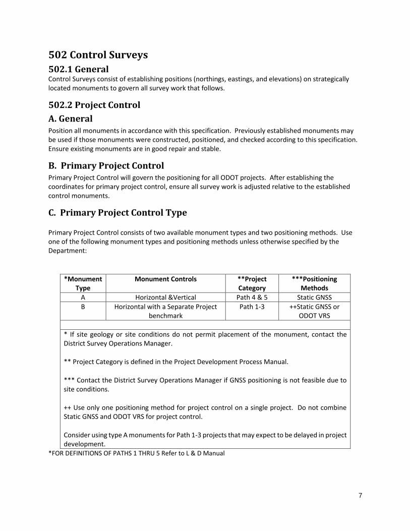
C. Primary Project Control Type
Primary Project Control consists of two available monument types and two positioning methods. Use one of the following monument types and positioning methods unless otherwise specified by the Department:
*Monument Type
Monument Controls **Project Category
***Positioning Methods
A Horizontal &Vertical Path 4 & 5 Static GNSS
B Horizontal with a Separate Project benchmark
Path 1-3 ++Static GNSS or ODOT VRS
* If site geology or site conditions do not permit placement of the monument, contact the District Survey Operations Manager.
** Project Category is defined in the Project Development Process Manual.
*** Contact the District Survey Operations Manager if GNSS positioning is not feasible due to site conditions.
++ Use only one positioning method for project control on a single project. Do not combine Static GNSS and ODOT VRS for project control.
Consider using type A monuments for Path 1-3 projects that may expect to be delayed in project development.
*FOR DEFINITIONS OF PATHS 1 THRU 5 Refer to L & D Manual

8
D. Primary Project Control Monuments
Construct primary project control monuments flush to the ground according to details shown in appendix H. Locate primary project control monuments inside the public right-of-way, within the vicinity of the project, and outside of the construction work limits. Contact the District Survey Operations Manager if placement is not possible as noted above. Placement of primary project control monuments is dependent upon the project length. Furnish primary project control monuments per the following table:
Primary Project Control Monument Placement
Project Length
Beginning & End of
Alignment
Approx. Interval Distance along
Alignment
At locations Specified by
District
Minimum # of Monuments
Required
Minimum # of Azimuth Marks
< 1mile x 2 1
≥1mile X 1 mile x 3 2
Establish a Type A azimuth mark for the Type A primary project control monuments at the beginning and end of the project. Use a cap identifying the point as “azimuth mark” in accordance with details shown in appendix H. Place the azimuth mark a minimum distance of 500 feet from the primary project control monument. Determine the horizontal and vertical position of the azimuth mark using the same positioning method, coordinate statistical analysis, and coordinate determination as the primary project control monuments. Ensure there is a clear line of sight from the primary project control monument to the azimuth mark. Contact the District Survey Operations Manager if the distance of 500 feet is not feasible due to site characteristics.
Establish a Type B azimuth mark for the Type B primary project control monuments at the beginning and end of the project. Determine the horizontal position of the azimuth mark using the same positioning method, coordinate statistical analysis, and coordinate determination as the primary project control monument. Each Type B primary project control monument will have a corresponding project benchmark, except Type B azimuth marks. Ensure project benchmarks are of a stable and permanent nature. Locate project benchmarks within a clear line of sight to the primary project control monument, outside of construction areas, clear of traffic, and within a public right of way or easement. Transfer the elevation of the Type B primary project control monument to the project benchmark using differential leveling in accordance with Section 502.4. Determine the vertical difference between the primary project control monument and the project benchmark within 3 days of the last GNSS observation on the primary project control monument. Contact the District Survey Operations Manager if the distance of 500 feet is not feasible due to site characteristics.
Ensure primary project control monuments are placed to have a clear view of the sky and to reduce the potential for GNSS multipath signals.

9
E. Survey Equipment
Use survey grade GNSS receivers and antennas in accordance with Section 600.
F. Static GNSS Data Collection
OPUS Solution for all Control Points
1.) Collect a minimum of 3 sessions of static GNSS data consisting of at least 4 hours per session for each primary project control monument. Ensure the survey equipment is removed and reinstalled over the monument between sessions. Ensure proper GNSS survey planning to achieve the required data quality as outlined in this specification. Consider the following when planning the GNSS survey: positional dilution of precision (PDOP), number of satellites, mask angle, collection rate, multipath, solar activity, etcetera.
Base Receiver Setup with Rover unit collecting Fast-Static data
2.) Establish a base receiver by collecting one primary control point near the center of the project using a minimum of 3 static GNSS sessions as in 3 above. Simultaneously collect the remaining primary control points using a GNSS rover collecting fast-static data. Collect each primary control point fast-static data for a minimum of 20 minutes plus 5 minutes per kilometer of baseline between the occupied control points.
CORS Station with Rover unit collecting Fast-Static data
3.) Using a nearby CORS Station as a base point, collect each primary control point fast-static data for a minimum of 20 minutes plus 5 minutes per kilometer of baseline between the occupied control point and the CORS Station. Post process fast-static data against the CORS Station.
G. Static GNSS Data Processing
OPUS Solution for all Control Points
1.) Process the collected data to determine the Northing, Easting, and Elevation (Orthometric Height) for each session using National Geodetic Survey’s OPUS (Online Positioning User Service). Use the rapid or precise ephemeris only. Ensure the correct antenna height, make, and model are utilized. Use the same three CORS base stations when processing a primary project control point in OPUS. The user must manually select the CORS stations to be used in the OPUS processing.
Base Receiver Setup with Rover unit collecting Fast-Static data
2.) Establish the base station coordinates to post process GNSS baselines 0.by submitting the GNSS data RINEX files to OPUS as in number 1 above. Process the collected GNSS data by importing into a GNSS post processing software such as Trimble Business Center, Leica Infinity, or

10
MAGNET, post process the GNSS baselines thru the appropriate post processing software. Calculate the positions of three observations per point and calculate the RMSE value to insure the control point meets the ODOT Survey and Mapping Specifications for a class “A’ monument.
CORS Station with Rover unit collecting Fast-Static data
3.) Use the published coordinate values of the nearest CORS station to post process GNSS baselines from. Process the collected GNSS data by importing into a GNSS post processing software such as Trimble Business Center, Leica Infinity, or MAGNET. Post process the GNSS baselines thru the appropriate post processing software. Calculate the positions of three observations per point and calculate the RMSE value to insure the control point meets the ODOT Survey and Mapping Specifications for a class “A’ monument.
H. ODOT VRS Data Collection
Collect the Northing, Easting, and Elevation coordinates using 5 second observations at a 1 second epoch rate. Collect a minimum of 12 observations for each project control monument. Note: More than 12 observations may be required to meet the minimum RMSE requirements specified below. Collect 4 observations rotating the Rod 90 degrees between each observation, remove the rod and break initialization, repeat observation procedures until 12 positions have been recorded. Consider the following when planning and performing VRS surveys: positional dilution of precision (PDOP), number of satellites, mask angle, multipath, solar activity, etcetera.
I. Coordinate Statistical Analysis
1. Calculate the Root Mean Square Error (RMSE) for each coordinate component (Northing, Easting, and Elevation) at each primary project control monument using the following equation:
N
CheckAverage
RMSEii
N
i
2
1
][
Averagei = Average position of the Northing, Easting, or Elevation value at a primary project control monument
Checki = Northing, Easting, or Elevation value from each individual GNSS static session at a project control monument or ODOT VRS observation at a primary project control monument
N = Number of sessions at a primary project control monument
An example calculation is included in Appendix D.

11
2. Ensure the RMSE for the Northing, Easting, and Elevation components do not exceed the maximum allowable RMSE for all project control monuments according to the following:
Coordinate Component Maximum Allowable RMSE Northing 0.029 feet [0.0088 meters] Easting 0.029 feet [0.0088 meters]
Elevation 0.039 feet [0.0119 meters]
3. Perform additional observations as required to meet the maximum allowable RMSE. Any combination of observations may be used to achieve the required RMSE, provided all coordinate components (Northing, Easting, and Elevation) are used in the solution.
In no case shall the overall accuracy of survey work performed for ODOT be less than 1 in 10,000
J. Primary Project Control Monument Horizontal Coordinates
The Northing and Easting of the primary project control monument coordinates are determined by taking the average of each coordinate component from the OPUS or ODOT VRS solutions that meet the RMSE requirements as specified in Section 502.2 I.
K. Primary Project Control Monument Vertical Coordinates
Establish the elevations of primary project control monuments or their associated project benchmarks by differential leveling. Refer to section 502.4 for leveling procedures. Differential leveling for primary project control monuments and project benchmarks will originate from, and close on, the primary project control monument closest to the center of the project with the lowest Elevation RMSE value. Level through all primary project control monuments as well as project benchmarks. Hold the elevation values established by differential leveling for all primary project control monuments. As a check, compare the leveled elevations to the GNSS determined elevations from Section 502.2 I. Highlight any differences that exceed 0.10 U.S. Survey Foot.
L. Secondary and Temporary Project Control
Secondary and temporary project control for surveying or construction purposes are to be positioned relative to the primary project control. Establish a monument type sufficient to ensure stability for the anticipated duration of project or task to be performed. Establish secondary and temporary project control at an accuracy to ensure locations conform to all Federal and State laws and ODOT specifications.
M. Project Scale Factor (Grid to Ground multiplier)
If a Project scale factor is required, use the following method for establishing the scale factor:
1. If Static GNSS is used to determine the positions for primary project control monuments, use the average of the OPUS calculated combined scale factors for the monument closest to the center of the project. Ensure the scale factor is calculated from OPUS solutions that meet the RMSE requirements. Scale the project about the origin of the coordinate system (0, 0).
2. If VRS is used to position primary project control monuments, perform a 20 minute static observation on the monument closest to the center of the project. Submit the static session to OPUS-RS to obtain the combined scale factor. Scale the project about the origin of the coordinate system (0, 0) using the project scale factor. Ensure coordinates and elevations obtained from OPUS-RS are not utilized.
12
3. Project scale factor may be derived by other means with approval of the District Survey Operations Manager (i.e. Data Collector solution, TBC, Infinity, Topcon tools) based on GNSS data collected for any individual point. The control point used should meet the RMSE requirements. Scale the project about the origin of the coordinate system (0, 0).
4. The Project Scale Factor shall be documented and used for all work on the project. 5. The Project scale factor shall be calculated by taking the inverse of the combined scale factor
(1/coordinate scale factor x ellipsoid height scale factor). 6. Site Calibration: Use a minimum of 4 points to calculate a horizontal site calibration and 5
control points to establish a vertical site calibration. The entire project should lie within the control point network. Hold the initial scale of the site calibration fixed at 1.000000 to determine if the horizontal and vertical residuals of the control points are within the current RMSE tolerances. If one or more control points are out of the current RMSE tolerances it can be discarded and another point added to the calibration. If you are performing a Site Calibration the Grid Coordinates, the GNSS observed Site Calibration Coordinates and the Horizontal and Vertical Residuals, shall be included in the final deliverables to the Survey Operations Manager. Consult the Survey Operations Manager regarding Site Calibrations that need to be performed on ODOT projects.
7. The Latitude of the Primary Project Control monument closest to the center of the project shall be used to calculate the Project Scale Factor for all projects regardless of the method used to locate the monument or method used to determine the Project Scale Factor. An ellipsoid height that is a good representation of the average height of the project site shall be used to calculate the elevation factor.
N. Deliverables
Furnish the following deliverables as soon as possible prior to the Beginning of Design:
1. Surveyor’s Certification Statement. A standard form is included in Appendix F. 2. A table that includes primary project control coordinates and azimuth mark coordinates. Include
the following in the table: a. Point Number b. Point Description c. Monument Type d. Positioning Method e. Grid Coordinates
a. Northing (meters) b. Easting (meters)
f. If applicable, Scaled Coordinates a. Northing (U.S. survey feet) b. Easting (U.S. survey feet)
g. If applicable, the Project Scale Factor and associated monument h. Type A primary project control orthometric heights (U.S. survey feet)
i. Project Benchmark number, description, and orthometric height listed with each Type B primary control monument
3. NGS OPUS data sheets if used in the solutions 4. NGS OPUS-RS data sheets if used to obtain a scale factor
13
5. Statistical analysis for each primary project control monument and azimuth mark(s). (See example, Appendix D)
6. Native survey data files in Trimble RAW or RINEX 2.0 format
7. A general map of the entire project with the project control monuments identified in PDF, Microstation (version according to ODOT CADD Engineering Standards Manual), or any standard raster format
8. All field notes, sketches, and adjustment calculations 9. All differential leveling deliverables as specified in Section 502.4 F. 10. Documentation confirming the calibration of all survey equipment used. 11. Copies of Ohio Utility Protection Service (OUPS) Tickets
Ensure all deliverables are on the same datum and coordinate system as specified in Section 300. Furnish deliverables to the District Survey Operations Manager prior to performing any additional work indicated in this specification. Allow 10 working days for review. Consultant may proceed at their own discretion if comments are not received after 10 working days. A licensed Professional Surveyor registered in the State of Ohio will sign, seal, and certify that all work performed meets or exceeds the requirements of this specification for primary project control.
502.3 Aerial Photo Ground Control
A. General
Aerial photo ground control is used to georeference images produced from aerial photography. Ensure adequate aerial photo control is used to correctly position images and subsequent products relative to the primary project control. Ensure the required DTM and Planimetric Accuracy Classes are met.
B. Aerial Targets
Place aerial targets at locations easily identified in aerial photographs. When possible, place all targets within the public right-of-way. Obtain permission prior to placing targets on private property.
The preferred target for aerial photography is a 4 foot by 4 foot cross, 8 inches in width. Use white thermoplastic material thoroughly adhered to the pavement. Other target sizes, shapes, or material may be utilized provided they are clearly visible in aerial photographs. Furnish a PK nail driven flush to the ground at the center of the target to serve as the target reference point.
Use a temporary cloth aerial target for non-pavement applications. Ensure the surface is relatively level. Pull the cloth target tight and securely stake the target to the ground, provide a wood hub and tack or Iron pin in the center of the target to serve as the target reference point.
C. Picture Points
Furnish picture point positions if aerial targets are not utilized. Select picture points that can easily be identified on the aerial photographs. Ensure the selected position is not obscured by shadows or directly adjacent to an object extending above the ground by more than 6 inches. Acceptable picture points include, but are not limited to the following:
1. Sidewalk corners 2. Stop bar pavement markings 3. Tip of pavement marking arrows 4. Concrete pad corners 5. Parking lot pavement markings

14
6. Top of grate corner for catch basins
Furnish a sketch of each picture point feature. Indicate the location of the surveyed point on the sketch.
D. Aerial Photo Ground Control Surveys
Collect coordinates and elevations at the center of the cross (aerial target) or at the selected picture point. Ensure all photo control is positioned relative to the primary project control. Document the survey procedures and methods used.
E. Survey Feature Codes
Use the following survey feature codes when collecting aerial photo control:
502.4 Differential Leveling A. General
Perform differential leveling to determine the orthometric height of primary project control monuments, temporary benchmarks, and other benchmarks. Differential leveling may also be performed to establish elevations of secondary and temporary control points as needed.
B. Project Benchmarks
Construct Project benchmarks in conjunction with Type B primary project control monuments. Construct Project benchmarks as required to complete project related tasks or where dictated by the District Survey Operations Manager. Ensure Project benchmarks are of a stable nature. Furnish Project benchmarks that are easily accessible, located outside of anticipated construction areas, clear of traffic, and within a public right of way or easement. Include a list of Project benchmarks with the deliverables. Ensure station/offset and descriptions are included. Commence and close all leveling for Project benchmarks from an established primary control point monument as specified in Section 502.2-k.
C. Differential Leveling Surveys
Complete leveling surveys to an accuracy required in this specification. Higher accuracy leveling may be required for certain projects or when specified by the District Survey Operations Manager. Ensure proper leveling procedures are followed to obtain the required accuracy. Consider balancing foresights and backsights, sight length limitations, and multiple rod readings to increase accuracy as needed. Use equipment meeting Section 600.
D. Closure Requirements
The maximum allowable mis-closure for all level loops is defined by the following equation:
0.04 feet x (√E)
E = Length of loop in miles (loop is defined as a series of setups closing on the starting point).
Re-level all level loops whose mis-closure exceeds this closure requirement.
Description Feature Code
Aerial Target AERTAR
Aerial Target - Picture Point AERPP

15
Consult district Survey Operations Manager if site conditions make it difficult to meet the published closure requirements.
E. Leveling adjustments
Adjust level loop mis-closures that fall within given closure requirements. Corrections for the closing error will be prorated equally to each turning point and benchmark between the controlling monument(s) for the length of the level loop.
F. Deliverables
1. Surveyor’s Certification Statement 2. Report of all primary project control, and Project benchmark elevations established. Include the
following as a minimum: point name, elevation, description of the mark and a sketch defining its location
3. Field notes for all leveling work 4. Listing of all field crew members/titles 5. Details of mis-closures, calculations and adjustments 6. Make, model, serial numbers and firmware versions of all equipment used 7. Post-processing software used with version number (where applicable) 8. A spreadsheet showing the differences between leveled and GNSS derived elevations for all Type
A primary project control monuments or Project benchmarks for Type B monuments. 9. Documentation confirming the calibration of applicable survey equipment used.
503 Boundary Surveys 503.1 General
ODOT surveying and mapping projects may require the location, retracement and establishment of boundaries including: private and public properties, federal, state, county and municipal boundaries, public land subdivisions, highway alignments, easements, etcetera. Ensure all ODOT boundary surveys originate from monumentation constructed and/or positioned according to this specification. Ensure conformance to all county, municipal and jurisdictional survey requirements for the project location. Complete all boundary work in accordance to O.A.C. 4733 & O.R.C. 4733 and the ODOT Right-of-Way Plan Manual.
503.2 Property Surveys
Property surveys are required for all parcels that may be legally affected, altered or transferred, either temporarily or permanently, as part of an ODOT project. Refer to the project scope of services or the District Survey Operations Manager for further project specific information.
503.3 Right of Way & Highway Centerline Surveys
All Right-of-Way and Highway Centerline surveys are governed by the Ohio Department of Transportation Right-of-Way Plan Manual, Sections 3103 and 3104.
16
504 Mapping Surveys 504.1 General A mapping survey is the collection of points to define the features (natural, man-made, or both) of a physical surface. Examples may include topographic surveys, bridge surveys, hydrographic surveys, and etcetera.
504.2 Topographic Surveys A topographic survey is the collection of points and attributes to define the shape of the Earth’s surface, including natural and man-made features.
A. Digital Terrain Model (DTM)
This specification covers Digital Terrain Models (DTMs) provided for ODOT projects. Ensure all deliverables use the same datum, coordinate system, and units specified in Sections 300 & 400, respectively. Ensure positioning is performed relative to primary project control.
B. Accuracies
The following accuracy classes are used in this specification:
DTM
Accuracy
Class Recommended Use
Maximum
Allowable
Average Dz
(feet)
Maximum
Allowable
RMSE (feet)
Class A Paved areas ± 0.07 0.16
Class B Vegetated areas outside of pavement that are maintained at a
minimum biannual frequency (i.e.: farm fields, residential
yards, roadside R/W, etcetera)
± 0.25 0.32
Class C Vegetated areas that are not maintained ± 0.50 0.50
Class D Areas where vertical accuracy is not critical or warranted (i.e.:
planning engineering projects)
± 1.00 1.00
C. Triangulated Irregular Network (TIN)
Create a TIN using Survey Points to obtain a DTM that meets the required Average Dz and RMSE for each DTM accuracy class. Ensure a sufficient number of Survey Points and break lines are collected to meet the required DTM Accuracy Class specified by the Department for each project. Remove vegetation, buildings, bridges, and other points that do not represent the ground. Ensure voids are placed within the TIN to prevent triangulation through water bodies and bridges. The TIN may be adjusted vertically

17
to ensure it meets the maximum allowable average Dz for the DTM accuracy class of the paved roadway surface. Ensure the vertical adjustment is applied uniformly to the entire DTM.
D. Vertical TIN Accuracy Testing Procedure
Collect Check Points per the following:
1. Collect cross sections perpendicular to the roadway alignment from proposed Right-of-Way to proposed Right-of-Way near the beginning and end of the alignment(s) and at an interval of approximately every 1 mile. Ensure the cross sections have sufficient points to clearly define the existing surface.
2. Collect a profile that is parallel to the roadway alignment along the painted pavement edge line for a minimum distance of 100 feet with Check Points spaced at approximately 5-foot intervals at each cross section area collected above.
3. Collect additional Check Points at locations specified by the District Survey Operations Manager.
Perform an RMSE calculation using the elevation values of the Check Points and the TIN at the same horizontal location for each area of accuracy class. Use all Check Points in the RMSE calculation for each area of accuracy class. Major errors or blunders in the Check Points may be eliminated if the rationale is well documented and submitted in the deliverables. Calculate the RMSE with the following equation:
N
onTinElevatiCheckpo
RMSEii
N
i
2
1
]int[
TinElevationi = Elevation generated from the ground surface TIN (feet).
CheckPointi = Elevation value from the Check Point (feet)
N = Total number of Check Points for each accuracy class area. Ensure enough Check Points are collected to represent different terrain and vegetation conditions for statistical validity.
An example calculation is included in Appendix B.
The Department may collect Check Points for an independent verification of the TIN anywhere within the project. Check Point locations will be determined by the Department. If the Department finds any area of the TIN to exceed the Maximum Allowable Average Dz or the Maximum Allowable RMSE for the specified DTM Accuracy Class, the consultant will perform any corrective work necessary to meet this specification at no additional cost to the Department within a time frame agreed upon by the Department and the consultant.
E. Deliverables
Furnish deliverables to the District Survey Operations Manager prior to performing any engineering design work. Deliverables may be sent in combination with Section 504.3 deliverables. Allow 10 working days for review. Consultant may proceed at their own discretion if comments are not received.

18
Ensure all CADD drawings conform to the ODOT CADD Engineering Standards Manual and are in units of U.S. survey feet. Ensure finished products use the same datum and coordinate system of Section 300.
Include the following deliverables as applicable:
1. Completed quality control report (example shown in Appendix C). 2. Identify all Check Points that were omitted in the analysis and the rationale for their removal. 3. GNSS/INS system lever arms for any airborne sensors utilized for the digital mapping. 4. Flight Log for any airborne sensors. Include the following information:
a. GNSS Base Station(s) used b. Date of flight c. Flight Altitude (AGL) d. Aircraft make and model e. Weather conditions f. Crew
5. DTM for existing ground in GEOPAK Binary TIN format including any break lines collected. Ensure individual files are less than or equal to 130MB in size.
6. Aero triangulation solution if applicable to the method of Survey Point collection. 7. Classified LiDAR Point Cloud in a LAS format if applicable to the data collection methodology. 8. A Microstation (version according to ODOT CADD Engineering Standards Manual) CADD drawing of
the entire project that includes the triangles of the existing TIN, and the location of all Survey and Check Points. Include contours at a 1 foot minor and 5 foot major contour interval. Provide labels for all major contours.
a. Ensure there is a title block that contains the following items: a. North Arrow b. Project Name c. Project PID d. Delivered Date e. Date of raw data collection (LiDAR, Photogrammetry, etc.) f. Coordinate System g. Datum h. Mapping Projection i. Geoid j. Combined Scale Factor k. Units (US Survey Feet)
9. Documentation confirming the calibration of all survey equipment used.
504.3 Planimetric Features A. Description
This specification covers collection of existing planimetric features and all known underground utilities. Aerial orthophotos are included with this specification and may be required in the scope of services. Ensure all deliverables use the same datum, coordinate system, and units specified in Sections 300 & 400, respectively. Ensure positioning is performed relative to primary project control.

19
B. Accuracy
The planimetric accuracy detail classes with the corresponding maximum allowable RMSE are
provided below:
Planimetric
Accuracy
Class
Recommended Use Maximum
Allowable
RMSE (ft.)
Class I Projects that require Class I planimetric features listed in Appendix A to
be identified and mapped (i.e.: design engineering projects)
0.30
Class II Projects that require Class II planimetric features listed in Appendix A
to be identified and mapped (i.e.: planning studies)
1.00
C. Horizontal Planimetric Feature Accuracy Testing Procedure
Planimetric features should be horizontally aligned, and will be reviewed visually by SOM or ODOT Mapping Staff. Items deemed to be too far off horizontally will be rejected and need to be recollected.
Use the following procedure to test the horizontal planimetric features (see Appendix B for an example):
1. Collect Planimetric Check Points along well defined planimetric features shown in the delivered mapping. Check points collected for the vertical DTM accuracy test may be utilized if they are on a planimetric feature (example: painted edge line). Collect Planimetric Check Points at each of the following locations:
a. Near the beginning of the roadway alignment(s). b. Near the ending of the roadway alignment(s). c. At an interval of approximately 1 mile along the roadway alignment(s). d. At locations specified by the District Survey Operations Manager.
2. Measure the Northing and Easting distances to the Planimetric Check Point using a perpendicular line from the planimetric feature to the Planimetric Check Point.
3. Perform an RMSE calculation using the Northing and Easting distance values. Use all Planimetric Check Points in the RMSE calculation. Major errors or blunders in the Planimetric Check Points may be eliminated if the rationale is well documented and submitted in the deliverables. Calculate the RMSE for both the Northing and Easting directions with the following equations:
N
stNorthingDi
NorthingRMSE
N
i
2
1
][
N
tEastingDis
EastingRMSE
N
i
2
1
][
Northing Distance = Distance in the Northing direction for a line drawn perpendicular from the planimetric feature to the Planimetric Check Point (feet).

20
Easting Distance = Distance in the Easting direction for a line drawn perpendicular from the planimetric feature to the Planimetric Check Point (feet).
N = Number of Planimetric Check Points used in analysis. Ensure sufficient Planimetric Check Points are collected to represent different terrain conditions for statistical validity. An example calculation is included in Appendix B.
The Department may collect Planimetric Check Points for an independent verification of the planimetric feature accuracies anywhere within the project. If the Department finds any planimetrics that exceed the maximum allowable RMSE, the Consultant will perform any corrective work necessary to meet this specification at no additional cost to the Department within a time frame agreed upon by the Department and the Consultant.
D. Orthophoto
Create an orthorectified image using a digital terrain model. Ensure the orthophoto is color, free of visible image smear, free of noticeable seam lines, free of artifacts, has a uniform tone and brightness, and is free of misalignment errors. Furnish an orthophoto that is rectified to the ground and bridge deck surfaces. “True orthophotos” of buildings, utilities, or other items (exclusive of bridge deck surfaces) that are 4 feet or more above the existing ground surface are not required. Ensure the pixel size of the orthophoto is less than or equal to 6 inches and the file size is less than 400MB.
E. Deliverables
Furnish deliverables to the District Survey Operations Manager prior to performing any engineering design work. Deliverables may be sent in combination with Section 504.2 deliverables. Allow 10 working days for review. Consultant may proceed at their own discretion if comments are not received. Ensure all CADD drawings conform to the ODOT CADD Engineering Standards Manual and are in units of U.S. survey feet. Ensure finished products use the same datum and coordinate system of section 300.
Include the following as applicable:
1. Completed quality control report (example shown in Appendix C). 2. Boresight alignment calibration parameters for any airborne sensors utilized for mapping. 3. Camera calibration certificate if a camera sensor was utilized. 4. Film negatives if a film camera was utilized 5. Individual processed digital images if a digital camera was utilized 6. GNSS/INS system lever arms for any airborne sensors utilized for the digital mapping. 7. Flight Log for any airborne sensors with the following information:
a. GNSS Base Station Used. b. Date of flight. c. Height AGL. d. Aircraft make and model. e. Weather conditions. f. Crew.
8. Aero triangulation solution if applicable to the method of planimetric feature collection.

21
9. List of all underground utilities that were notified. Include contact names, telephone numbers, and addresses.
10. Include sketches of underground utility structures. Indicate conduit type, size, invert elevations, and direction of flow (if applicable) in the sketch.
11. Georeferenced Orthophoto in a TIFF format. 12. A Microstation CADD (version according to ODOT CADD Engineering Standards Manual) drawing of
the entire project that includes planimetric features and planimetric check points. Use a scale of 1 to 1 with the model annotation scale for existing planimetric features set at 1 inch=50 feet. Ensure the planimetric features use the same datum and coordinate system of section 300. Include all planimetrics required for the specified planimetric accuracy class (see appendix A). Ensure there is a block that contains the following items:
a. North Arrow b. Project Name c. Project PID d. Delivered Date e. Date of raw data collection (Lidar, Photogrammetry, etc.) f. Coordinate System g. Datum h. Mapping Projection i. Geoid j. Combined Scale Factor
k. Units (US Survey Feet) 13. Documentation confirming the calibration of all survey equipment used.
504.4 Bridge Bridge survey information is dependent upon the structure type and anticipated type of work. The Project Engineer should direct the survey crew in accordance to the needs of the project. Typical items included in a bridge survey may include one or more of the following: bearing seat elevations, dimension and shape of piers, profile of crown of pavement on bridge deck, profile of edge of pavement along bridge deck, profile of crown of pavement and both edges of pavement leading up to and away from bridge, bottom of beam profile for all beams, distance between the backwall and the edge of all beams, vertical clearance at crown of pavement, and all painted edge lines or changes in section grade.
Additional items may be required if the bridge spans a water course, such as: The Ordinary High Water Mark (OHWM), cross sections of the watercourse upstream and downstream, or the watercourse bottom measured radially from each pier.
Ensure all profiles include sufficient survey density to accurately depict each item. Include the coordinate location and orthometric height of all surveyed items.
504.5 Hydrographic Hydrographic surveys may be required for particular projects that require information such as: depth of water, topography of the bottom, direction of currents, and locations of fixed objects. This type of survey is unique and requires the combination of various surveying technologies to perform. Contact the District if this type of survey is required.

22
505 Construction 505.1 General Construction surveys are performed in order to construct the project in accordance with the plans. Regardless of the methodology for constructing the project, a minimum amount of construction staking must be furnished for the Department to verify conformance to the design plans.
505.2 Construction Staking Staking along the mainline is covered under Supplemental Specification 823. Staking at other significant items such as structures, utilities, earthwork, etc. is required throughout the project at sufficient density to ensure the Department can verify the work performed by the Contractor. Contact the Project Engineer to ensure adequate construction staking is furnished.
Furnish all staking information to the Project Engineer. Include the following staking information for points established: station with offset and direction, feature description, elevation, cut/fill, and any other information as requested by the Project Engineer.
505.3 Machine Control The construction industry continues to develop innovative equipment and methodologies that allow the use of “machine control” to improve performance and productivity. Machine control is typically defined as the automatic control of a machine or portions of a machine to achieve the desired results. Operations involving machine control may be based on one or more of a variety of technologies such as rotating lasers, total stations, proximity sensors, GNSS, INS, etcetera. If a contractor elects to use any type of machine control, they are responsible to ensure that the selected technology and operations meet the project requirements. The contractor will not be granted an extension to the completion date (intermediate or final) due to machine control related issues or problems.
600 Survey Equipment 601 Equipment Care and Maintenance Proper handling and servicing of all surveying equipment is essential to achieving the accuracy and precision required for ODOT projects. Careful handling of high accuracy instrumentation such as total stations, levels, GNSS receivers and other components is critical. Replace or repair broken, faulty, or inaccurate equipment prior to performing ODOT survey work.
602 Equipment Types and Specifications
602.1 Levels Optical and digital levels are acceptable for leveling operations. Leveling rods are to be single section or multi-section fiberglass, wood, or metal. Leveling instruments are required to meet the following minimum manufacturer specifications:
1. Internal compensator/auto-level. 2. Height accuracy of ± 1.5mm standard deviation for 1km double run leveling.

23
602.2 Total Stations Total Stations are to be capable of measuring horizontal angles, vertical angles and distances electronically in a single unit. Total stations are required to meet the following minimum manufacturer specifications:
1. Compensated with a dual axis compensator. 2. Horizontal and vertical angular accuracy of 5 seconds. 3. EDM accuracy of ± (3mm + 3ppm) to a reflective prism.
602.3 GNSS Receivers GNSS receivers are to be survey grade units and are required to meet the following minimum specifications as provided by the manufacturer:
1. Capable of tracking L1 and L2 frequency signals. 2. Static positioning accuracy of 5mm+1ppm horizontal/6mm+1ppm vertical (post processed). 3. Kinematic positioning accuracy of 10mm+1ppm horizontal/20mm+1ppm vertical.
603 Equipment Calibration and Maintenance Ensure all surveying equipment is calibrated and adjusted in accordance with the manufacturer’s recommendations. Documentation of all equipment adjustments and calibrations shall be kept and made available to ODOT upon request. Refer to the following criteria as a minimum for equipment maintenance:
603.1 Levels Ensure professional calibration and servicing is performed per the manufacturer’s specifications.
In addition, perform maintenance and care according to the following schedule:
Every 3 Months:
1. Clean and inspect optics, electrical contacts, instrument body, and instrument case 2. Check and adjust level vials 3. Peg test the level and adjust as needed
603.2 Total Stations Ensure professional calibration and servicing is performed per the manufacturer’s specifications.
In addition, perform maintenance and care according to the following schedule:
Every 3 Months:
1. Clean and inspect optics, electrical contacts, instrument body, and instrument case 2. Check and adjust level vials 3. Check and adjust vertical plummet 4. Check horizontal and vertical circle collimation and adjust as needed
Every 6 Months:
1. Check calibration of E.D.M. on a baseline and adjust as needed

24
603.3 Tripods, Tribrach’s, Prism Rods, and RTK Rods Perform maintenance and care according to the following schedule:
Every 3 Months:
1. Clean and inspect 2. Adjust level vials 3. Adjust the optical plummet 4. Tighten all clamps, locks, feet and screws to the proper specification

25
(This page left intentionally blank)
26
Appendix A –Planimetric Collection

27
Planimetric accuracy Class I projects require more detail than planimetric accuracy Class II projects. Include the following planimetric features according to the accuracy class specified by the Scope of Work:
Class I Planimetric Features 1. Edge of pavement (i.e.: paint line) 2. Edge of treated shoulder 3. Edge of graded shoulder 4. Driveways 5. Bikeways 6. Parking Lots 7. Bridge Deck 8. Streams, Rivers, Ponds, Lakes, Wetlands 9. Sidewalks 10. Highway barriers 11. Walls (retaining, headwalls, etc.) 12. Buildings 13. Utilities
a. Power Poles b. Manholes c. Light Pole d. Telecommunication poles e. Unknown poles f. Fire Hydrants g. Catch Basins h. Underground utilities from field collection
14. Traffic Signs (specify number of posts, sign size, and sign message in survey notes) 15. Above Ground Tanks (oil/gas) 16. Large piles (junk yard, stockpiles of material, etc.) 17. Above Ground Pumps 18. Mailbox (specify number of mailboxes in survey notes) 19. Cemeteries
a. Roads b. Buildings c. Estimated Cemetery boundary
20. Yard Lights 21. Airport Lights 22. Airport Windsock 23. Basket Ball Hoops 24. Flag Poles 25. Landscaping
a. Bushes (individual and lines) b. Rocks (Boulders) c. Flower Beds d. Trees (individual sizes according CMS Item 201)
i. Evergreen ii. Deciduous
iii. Stumps

28
e. Shrubs (individual) 26. Golf Course greens 27. School Playgrounds (Equipment not itemized) 28. Swimming pools 29. Ground based/mounted satellite dishes 30. Towers
a. Cell phone b. Etc.
31. Fences 32. Guardrail 33. Bird houses (unknown post) 34. Traffic Mast arms 35. Culverts 36. Trails (dirt roads) 37. Railroads 38. Billboards 39. Utility boxes 40. Survey Control Points for AT solution 41. Any other item(s) that will be significant to the cost of an engineering project or that have been
identified by the District Survey Operations Manager that are not listed above. These items may require a higher order of accuracy as specified by the District Survey Operations Manager.

29
Class II Planimetric Features 1. Edge of pavement (i.e.: paint line) 2. Edge of treated shoulder 3. Driveways 4. Bikeways 5. Parking Lots 6. Bridge Deck 7. Streams, Rivers, Ponds, Lakes, Wetlands 8. Highway barriers 9. Walls (retaining, headwalls, etc.) 10. Buildings 11. Utilities
a. Power Poles b. Manholes c. Light Pole d. Telecommunication poles e. Unknown poles f. Fire Hydrants g. Catch Basins h. Underground utilities from field collection
12. Above Ground Tanks (oil/gas) 13. Cemeteries
a. Roads b. Buildings c. Estimated Cemetery boundary
14. Swimming pools 15. Towers
a. Cell phone b. Etc.
16. Culverts 17. Railroads 18. Utility boxes 19. Survey Control Points for AT solution 20. Any other item(s) that will be significant to the cost of a planning project or that have been
identified by the District Survey Operations Manager that are not listed above.

30
(This page left intentionally blank)

31
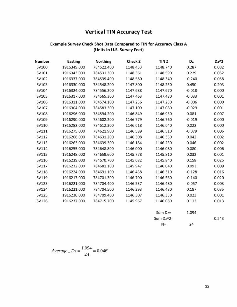
Appendix B –Example RMSE Calculation for Vertical TIN & Horizontal Planimetric Features
32
Vertical TIN Accuracy Test
Example Survey Check Shot Data Compared to TIN for Accuracy Class A
(Units in U.S. Survey Feet)
Number Easting Northing Check Z TIN Z Dz Dz^2
SV100 1916349.000 784522.400 1148.453 1148.740 0.287 0.082
SV101 1916343.000 784531.300 1148.361 1148.590 0.229 0.052
SV102 1916337.000 784539.400 1148.580 1148.340 -0.240 0.058
SV103 1916330.000 784548.200 1147.800 1148.250 0.450 0.203
SV104 1916324.000 784556.200 1147.688 1147.670 -0.018 0.000
SV105 1916317.000 784565.300 1147.463 1147.430 -0.033 0.001
SV106 1916311.000 784574.100 1147.236 1147.230 -0.006 0.000
SV107 1916304.000 784583.300 1147.109 1147.080 -0.029 0.001
SV108 1916296.000 784594.200 1146.849 1146.930 0.081 0.007
SV109 1916290.000 784602.200 1146.779 1146.760 -0.019 0.000
SV110 1916282.000 784612.300 1146.618 1146.640 0.022 0.000
SV111 1916275.000 784621.900 1146.589 1146.510 -0.079 0.006
SV112 1916268.000 784631.200 1146.308 1146.350 0.042 0.002
SV113 1916263.000 784639.300 1146.184 1146.230 0.046 0.002
SV114 1916255.000 784648.800 1146.000 1146.080 0.080 0.006
SV115 1916248.000 784659.600 1145.778 1145.810 0.032 0.001
SV116 1916239.000 784670.700 1145.682 1145.840 0.158 0.025
SV117 1916232.000 784681.100 1145.947 1146.040 0.093 0.009
SV118 1916224.000 784691.100 1146.438 1146.310 -0.128 0.016
SV119 1916217.000 784701.300 1146.700 1146.560 -0.140 0.020
SV123 1916221.000 784704.400 1146.537 1146.480 -0.057 0.003
SV124 1916221.000 784704.500 1146.293 1146.480 0.187 0.035
SV125 1916230.000 784709.400 1146.307 1146.330 0.023 0.001
SV126 1916237.000 784715.700 1145.967 1146.080 0.113 0.013
Sum Dz= 1.094
Sum Dz^2= 0.543
N= 24
'046.024
094.1_ DzAverage

33
'150.024
543.0RMSE
Horizontal Planimetric Feature Accuracy Test
Planimetric Feature = Edge of pavement paint line
Survey Point # ∆ Easting (∆ Easting)^2 ∆ Northing (∆ Northing)^2
100 0.131 0.017 0.104 0.011
101 0.148 0.022 0.117 0.014
102 0.138 0.019 0.109 0.012
103 0.149 0.022 0.118 0.014
104 0.202 0.041 0.157 0.025
105 0.186 0.035 0.145 0.021
106 0.171 0.029 0.133 0.018
107 0.227 0.052 0.176 0.031
108 0.243 0.059 0.189 0.036
109 0.238 0.057 0.185 0.034
110 0.221 0.049 0.171 0.029
111 0.278 0.077 0.216 0.047
112 0.196 0.038 0.152 0.023
113 0.282 0.080 0.219 0.048
114 0.116 0.013 0.091 0.008
115 0.256 0.066 0.200 0.040
116 0.216 0.047 0.169 0.029
117 0.287 0.082 0.224 0.050
118 0.226 0.051 0.177 0.031
119 0.259 0.067 0.202 0.041
120 0.217 0.047 0.169 0.029
121 0.219 0.048 0.168 0.028
122 0.171 0.029 0.132 0.017
123 0.252 0.064 0.194 0.038
124 0.201 0.040 0.155 0.024
125 0.126 0.016 0.097 0.009
126 0.200 0.040 0.154 0.024
127 0.034 0.001 0.027 0.001
128 0.139 0.019 0.108 0.012
129 0.164 0.027 0.128 0.016
130 0.090 0.008 0.161 0.026
Sum= 1.262 Sum= 0.786

34
'202.031
262.1gRMSEEastin '159.0
31
786.0ngRMSENorthi

35
Graphic of Horizontal Planimetric Feature Test on Painted Edge Line
Δ Northing
Painted Edge Line Δ Northing
Planimetric
Check Point
Planimetric
Check Point
Measurements are taken perpendicular to the center of the painted edge line. Determine the Δ Northing and Δ
Easting components for use in Horizontal Planimetric Feature Accuracy Test.
Δ Easting
Δ Easting

36
(This page left intentionally blank)

37
Appendix C –Example Mapping Quality Control Report

38
Mapping & Survey Quality Control Report for:
TUS-800-25.65
PID #101531
Report Submitted by:
Kyle Ince
Mapping Performed by:
CADD and Mapping Services Staff
Mapping Checked by:
Kyle Ince
Surveying Performed by:
District Survey
Survey Checked by:
District Survey
The above parties certify the mapping furnished with this project meets the requirements of the
ODOT Mapping Specifications, dated July 19, 2013.
39
General Comments Attached is the quality control report for the mapping and survey work for this project. The mapping was compiled for design engineering use. Project control is not included with this report. Hard Surface is only accurate from date of flight (03/07/2016) Datum and Coordinate Systems Vertical Orthometric Height Datum: NAVD88 Geoid Model: GEOID12B Horizontal Coordinate System: Ohio State Plane, North Zone Map Projection: Lambert Conformal Conic Reference Frame: NAD83 (2011) Ellipsoid: GRS80 Combined Scale Factor: 1.0000000000 Units All units are US Survey Feet.

40
Digital Terrain Model Methodology & Equipment Used Check points were collected using ODOT VRS. Survey points were collected using an Airborne LiDAR sensor with GPS/IMU navigation system. The entire DTM was vertically adjusted to the Check Points by: -0.5760 feet DTM Accuracy Class A – Paved Surfaces
Average Dz: 0.00‘ RMSE 0.07‘
DTM Accuracy Class B – Vegetated Surfaces
Average Dz: 0.07‘ RMSE 0.17‘
Data Used for Statistical Analysis is attached. Additional DTM Notes:
- Project is mapped for DTM Accuracy Class A on the pavement and DTM
Accuracy Class B off of the pavement.
- All subsurface drainage, ditch inverts, or channel inverts require field collection
and inclusion into the furnished existing surface model.
- Areas with dense brush or heavy vegetation require field collection and inclusion
into the existing surface model.
- Retaining walls and bridges require field collection and inclusion into the existing surface model.

41
Digital Mapping Methodology & Equipment Used Check points were collected using RTK ODOT VRS. Survey points were collected using digital camera with a GPS/IMU navigation system, aerotriangulation, and Photogrammetric 3D stereo planimetric collection. Additional Digital Mapping Notes:
- Project is mapped for Planimetric Accuracy Class I. - All subsurface utilities require field collection.
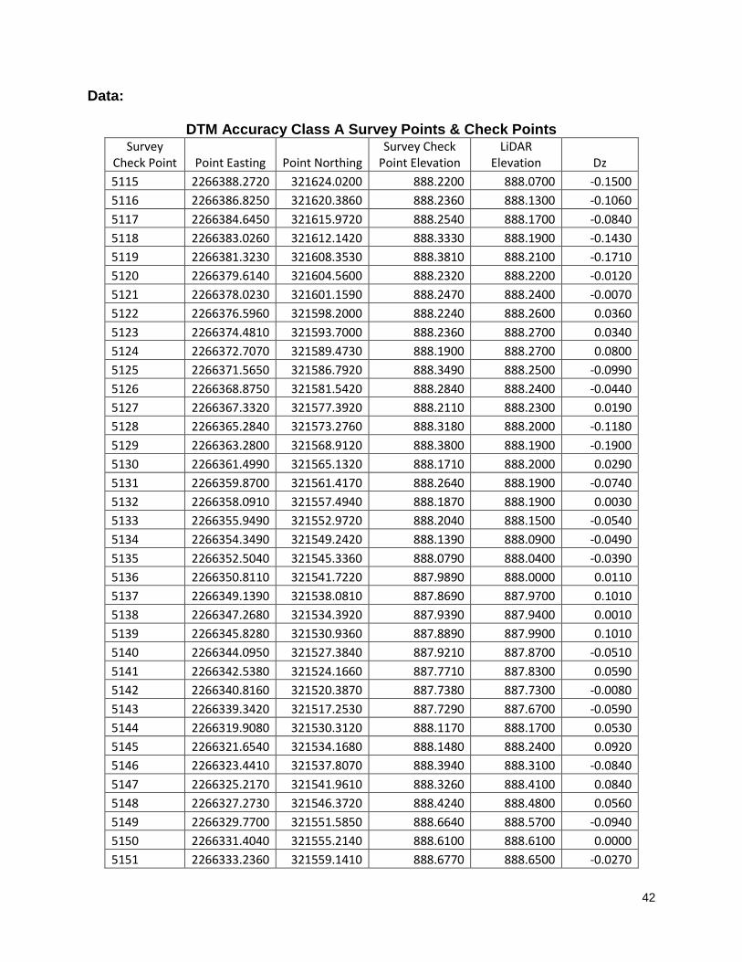
42
Data:
DTM Accuracy Class A Survey Points & Check Points Survey
Check Point Point Easting Point Northing Survey Check
Point Elevation LiDAR
Elevation Dz
5115 2266388.2720 321624.0200 888.2200 888.0700 -0.1500
5116 2266386.8250 321620.3860 888.2360 888.1300 -0.1060
5117 2266384.6450 321615.9720 888.2540 888.1700 -0.0840
5118 2266383.0260 321612.1420 888.3330 888.1900 -0.1430
5119 2266381.3230 321608.3530 888.3810 888.2100 -0.1710
5120 2266379.6140 321604.5600 888.2320 888.2200 -0.0120
5121 2266378.0230 321601.1590 888.2470 888.2400 -0.0070
5122 2266376.5960 321598.2000 888.2240 888.2600 0.0360
5123 2266374.4810 321593.7000 888.2360 888.2700 0.0340
5124 2266372.7070 321589.4730 888.1900 888.2700 0.0800
5125 2266371.5650 321586.7920 888.3490 888.2500 -0.0990
5126 2266368.8750 321581.5420 888.2840 888.2400 -0.0440
5127 2266367.3320 321577.3920 888.2110 888.2300 0.0190
5128 2266365.2840 321573.2760 888.3180 888.2000 -0.1180
5129 2266363.2800 321568.9120 888.3800 888.1900 -0.1900
5130 2266361.4990 321565.1320 888.1710 888.2000 0.0290
5131 2266359.8700 321561.4170 888.2640 888.1900 -0.0740
5132 2266358.0910 321557.4940 888.1870 888.1900 0.0030
5133 2266355.9490 321552.9720 888.2040 888.1500 -0.0540
5134 2266354.3490 321549.2420 888.1390 888.0900 -0.0490
5135 2266352.5040 321545.3360 888.0790 888.0400 -0.0390
5136 2266350.8110 321541.7220 887.9890 888.0000 0.0110
5137 2266349.1390 321538.0810 887.8690 887.9700 0.1010
5138 2266347.2680 321534.3920 887.9390 887.9400 0.0010
5139 2266345.8280 321530.9360 887.8890 887.9900 0.1010
5140 2266344.0950 321527.3840 887.9210 887.8700 -0.0510
5141 2266342.5380 321524.1660 887.7710 887.8300 0.0590
5142 2266340.8160 321520.3870 887.7380 887.7300 -0.0080
5143 2266339.3420 321517.2530 887.7290 887.6700 -0.0590
5144 2266319.9080 321530.3120 888.1170 888.1700 0.0530
5145 2266321.6540 321534.1680 888.1480 888.2400 0.0920
5146 2266323.4410 321537.8070 888.3940 888.3100 -0.0840
5147 2266325.2170 321541.9610 888.3260 888.4100 0.0840
5148 2266327.2730 321546.3720 888.4240 888.4800 0.0560
5149 2266329.7700 321551.5850 888.6640 888.5700 -0.0940
5150 2266331.4040 321555.2140 888.6100 888.6100 0.0000
5151 2266333.2360 321559.1410 888.6770 888.6500 -0.0270

43
5152 2266335.5170 321564.0080 888.8300 888.7100 -0.1200
5153 2266337.1980 321567.7920 888.7310 888.7300 -0.0010
5154 2266338.9030 321571.3290 888.8740 888.7800 -0.0940
5155 2266340.5390 321574.7320 888.8100 888.8000 -0.0100
5156 2266342.8980 321579.9650 888.8660 888.8200 -0.0460
5157 2266342.8410 321579.9090 888.8800 888.8200 -0.0600
5158 2266344.5620 321583.9990 888.8020 888.8500 0.0480
5159 2266346.4540 321587.7430 888.8330 888.8700 0.0370
5160 2266348.5360 321591.8890 888.9440 888.9000 -0.0440
5161 2266349.8800 321595.3360 888.9000 888.9100 0.0100
5162 2266351.3160 321598.5450 888.9450 888.9400 -0.0050
5163 2266352.9250 321602.0250 888.9640 888.9500 -0.0140
5164 2266354.9580 321606.2390 888.9260 888.9900 0.0640
5165 2266356.6340 321610.2080 889.0780 889.0000 -0.0780
5166 2266358.3290 321614.1940 889.0480 888.9700 -0.0780
5167 2266360.2180 321618.2270 888.9840 888.9100 -0.0740
5168 2266362.1290 321622.8230 888.9260 888.8700 -0.0560
5169 2266364.2060 321627.3000 888.8370 888.8500 0.0130
5170 2266365.9940 321631.1960 888.7710 888.8200 0.0490
5171 2266376.2450 321625.4850 888.7420 888.7100 -0.0320
5172 2266374.1660 321620.8530 888.8000 888.7700 -0.0300
5173 2266371.7240 321615.9020 888.7600 888.8200 0.0600
5174 2266369.5160 321610.7450 888.8320 888.8300 -0.0020
5175 2266367.2450 321605.6170 888.9790 888.8400 -0.1390
5176 2266364.8370 321600.4150 888.9280 888.8400 -0.0880
5177 2266362.9060 321595.9000 888.8080 888.8400 0.0320
5178 2266361.0890 321591.9630 888.7990 888.8400 0.0410
5179 2266359.3020 321588.1730 888.8260 888.8500 0.0240
5180 2266357.4460 321583.9180 888.7480 888.8300 0.0820
5181 2266355.0020 321578.6970 888.7020 888.7900 0.0880
5182 2266353.7440 321575.2010 888.7810 888.7600 -0.0210
5183 2266350.5340 321567.9750 888.7330 888.7200 -0.0130
5184 2266348.2460 321563.8590 888.6210 888.6600 0.0390
5185 2266346.2860 321559.5090 888.5570 888.6100 0.0530
5186 2266344.1370 321554.9160 888.5700 888.5700 0.0000
5187 2266342.4020 321551.0210 888.5430 888.5200 -0.0230
5188 2266340.1680 321546.4280 888.4140 888.4400 0.0260
5189 2266338.0470 321541.9760 888.4570 888.3800 -0.0770
5190 2266335.0230 321535.5230 888.2290 888.3300 0.1010

44
5191 2266332.7590 321530.3070 888.0920 888.2500 0.1580
5192 2266330.4820 321525.1320 888.0490 888.1500 0.1010
5198 2266318.1050 321526.4610 888.0080 888.0800 0.0720
5199 2266323.0720 321523.5340 887.9990 888.0700 0.0710
5200 2266328.5570 321520.9910 887.9450 888.0500 0.1050
5201 2266333.3810 321518.6140 887.7310 887.9100 0.1790
5202 2266338.8220 321515.8730 887.5150 887.6300 0.1150
5212 2266362.7740 321567.3820 888.2010 888.1800 -0.0210
5213 2266356.8380 321570.3690 888.5100 888.5500 0.0400
5214 2266352.2450 321572.2160 888.7830 888.7400 -0.0430
5215 2266347.7750 321575.1100 888.8580 888.8300 -0.0280
5216 2266341.9430 321577.8030 888.7700 888.8100 0.0400
5229 2266367.1110 321633.6810 888.7130 888.7900 0.0770
5230 2266372.7890 321630.7920 888.7250 888.7300 0.0050
5231 2266377.6360 321628.5440 888.6950 888.6700 -0.0250
5232 2266382.6870 321626.4460 888.3910 888.4500 0.0590
5233 2266388.3100 321624.0390 888.1020 888.0700 -0.0320
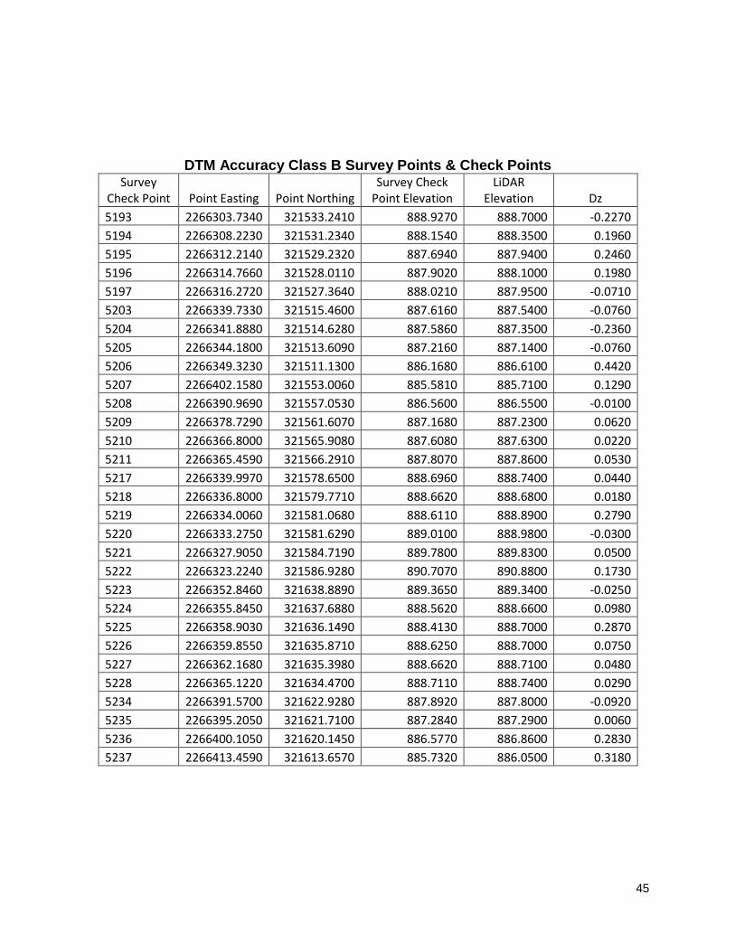
45
DTM Accuracy Class B Survey Points & Check Points Survey
Check Point Point Easting Point Northing Survey Check
Point Elevation LiDAR
Elevation Dz
5193 2266303.7340 321533.2410 888.9270 888.7000 -0.2270
5194 2266308.2230 321531.2340 888.1540 888.3500 0.1960
5195 2266312.2140 321529.2320 887.6940 887.9400 0.2460
5196 2266314.7660 321528.0110 887.9020 888.1000 0.1980
5197 2266316.2720 321527.3640 888.0210 887.9500 -0.0710
5203 2266339.7330 321515.4600 887.6160 887.5400 -0.0760
5204 2266341.8880 321514.6280 887.5860 887.3500 -0.2360
5205 2266344.1800 321513.6090 887.2160 887.1400 -0.0760
5206 2266349.3230 321511.1300 886.1680 886.6100 0.4420
5207 2266402.1580 321553.0060 885.5810 885.7100 0.1290
5208 2266390.9690 321557.0530 886.5600 886.5500 -0.0100
5209 2266378.7290 321561.6070 887.1680 887.2300 0.0620
5210 2266366.8000 321565.9080 887.6080 887.6300 0.0220
5211 2266365.4590 321566.2910 887.8070 887.8600 0.0530
5217 2266339.9970 321578.6500 888.6960 888.7400 0.0440
5218 2266336.8000 321579.7710 888.6620 888.6800 0.0180
5219 2266334.0060 321581.0680 888.6110 888.8900 0.2790
5220 2266333.2750 321581.6290 889.0100 888.9800 -0.0300
5221 2266327.9050 321584.7190 889.7800 889.8300 0.0500
5222 2266323.2240 321586.9280 890.7070 890.8800 0.1730
5223 2266352.8460 321638.8890 889.3650 889.3400 -0.0250
5224 2266355.8450 321637.6880 888.5620 888.6600 0.0980
5225 2266358.9030 321636.1490 888.4130 888.7000 0.2870
5226 2266359.8550 321635.8710 888.6250 888.7000 0.0750
5227 2266362.1680 321635.3980 888.6620 888.7100 0.0480
5228 2266365.1220 321634.4700 888.7110 888.7400 0.0290
5234 2266391.5700 321622.9280 887.8920 887.8000 -0.0920
5235 2266395.2050 321621.7100 887.2840 887.2900 0.0060
5236 2266400.1050 321620.1450 886.5770 886.8600 0.2830
5237 2266413.4590 321613.6570 885.7320 886.0500 0.3180

46
Appendix D – Example Static GNSS Coordinate Statistical Analysis

47
PR
OJE
CT
:R
EP
OR
T D
AT
E:
11/1
5/2
013
PID
:87695
PR
EP
AR
ED
BY
:J. K
elle
r
CP
01
NU
MB
ER
OF
SE
SS
ION
S:
12
CH
EC
KE
D B
Y:
J. K
elle
r
SE
SS
ION
#P
oin
tO
bserv
atio
n D
ate
Sta
rt Tim
eN
orth
ing
(m)
Eastin
g(m
)H
eig
ht(m
)∆
No
rthin
g(m
)∆
Eastin
g(m
)∆
Heig
ht(m
)In
clu
de in
So
lutio
n?
1C
P01
11.1
4.2
013
10:1
1:5
8 A
M116107.0
6410
609689.5
0720
362.5
5740
0.0
1280
-0.0
0795
0.0
1785
TR
UE
2C
P01
11.1
4.2
013
10:1
3:1
4 A
M116107.0
7550
609689.5
1180
362.5
5180
0.0
0140
-0.0
1255
0.0
2345
FA
LS
E
3C
P01
11.1
4.2
013
10:1
3:4
8 A
M116107.0
7510
609689.5
0370
362.5
7220
0.0
0180
-0.0
0445
0.0
0305
TR
UE
4C
P01
11.1
4.2
013
10:1
4:1
1 A
M116107.0
6330
609689.4
9700
362.5
9260
0.0
1360
0.0
0225
-0.0
1735
FA
LS
E
5C
P01
11.1
4.2
013
10:1
5:1
7 A
M116107.0
7620
609689.4
8920
362.5
8540
0.0
0070
0.0
1005
-0.0
1015
TR
UE
6C
P01
11.1
4.2
013
10:1
5:4
0 A
M116107.0
7700
609689.4
8670
362.5
9100
-0.0
0010
0.0
1255
-0.0
1575
TR
UE
7C
P01
11.1
4.2
013
10:1
6:1
2 A
M116107.0
9600
609689.4
8740
362.5
9220
-0.0
1910
0.0
1185
-0.0
1695
FA
LS
E
8C
P01
11.1
4.2
013
10:1
6:3
7 A
M116107.0
8800
609689.4
8190
362.5
9530
-0.0
1110
0.0
1735
-0.0
2005
FA
LS
E
9C
P01
11.1
4.2
013
10:1
7:4
1 A
M116107.1
0300
609689.4
9490
362.5
6990
-0.0
2610
0.0
0435
0.0
0535
FA
LS
E
10
CP
01
11.1
4.2
013
10:1
8:1
6 A
M116107.0
8550
609689.5
0060
362.5
6870
-0.0
0860
-0.0
0135
0.0
0655
TR
UE
11
CP
01
11.1
4.2
013
10:1
8:4
1 A
M116107.0
8660
609689.5
0670
362.5
5570
-0.0
0970
-0.0
0745
0.0
1955
FA
LS
E
12
CP
01
11.1
4.2
013
10:1
9:1
7 A
M116107.0
8350
609689.5
0810
362.5
7680
-0.0
0660
-0.0
0885
-0.0
0155
TR
UE
13
00:0
0:0
012:0
0:0
0 A
M0.0
0000
0.0
0000
0.0
0000
0.0
0000
0.0
0000
0.0
0000
FA
LS
E
14
00:0
0:0
012:0
0:0
0 A
M0.0
0000
0.0
0000
0.0
0000
0.0
0000
0.0
0000
0.0
0000
FA
LS
E
15
00:0
0:0
012:0
0:0
0 A
M0.0
0000
0.0
0000
0.0
0000
0.0
0000
0.0
0000
0.0
0000
FA
LS
E
AV
ER
AG
E116107.0
7690
609689.4
9925
362.5
7525
RM
SE
:R
MS
E:
RM
SE
:
RM
SE IN M
ETRIC
:0.0
0689
0.0
0838
0.0
1099
EN
GL
ISH
TO
ME
TR
IC C
ON
VE
RS
ION
3.2
80833333
RM
SE IN U
S SUR
VEY FEET:
0.0
22
60
.02
75
0.0
36
0U
NIT
LE
SS
GR
ID T
O G
RO
UN
D M
UL
TIP
LIE
R1
.00
00
90
87
2P
AS
SP
AS
SP
AS
S
No
tes:
NO
RT
HIN
GE
AS
TIN
GO
RT
HO
HE
IGH
T
116107.0
769
609689.4
993
362.5
753
US
SU
RV
EY
FE
ET
1189.5
49
(Typ
e th
e le
vele
d e
levatio
n o
r N/A
if no
levele
d e
levatio
n is
availa
ble
)
MO
NU
ME
NT
HE
LD
CP
01
(Typ
e th
e m
on
um
en
t nam
e fro
m w
hic
h le
velin
g o
rigin
ate
d)
LE
VL
ED
EL
EV
AT
ION
- GP
S D
ER
IVE
D E
LE
VA
TIO
N =
0
.00
0
NO
RT
HIN
GE
AS
TIN
GE
LE
VA
TIO
NF
EA
TU
RE
CO
DE
380927.9
68
2000289.6
32
1189.5
49
IPIN
S
380962.5
84
2000471.4
03
1189.5
49
IPIN
S
∆ N
orth
, ∆ E
ast, a
nd
∆ H
t. are
the d
iffere
nce b
etw
een
the a
vera
ge n
orth
ing
, eastin
g, a
nd
heig
ht fo
r each
ob
serv
atio
n.
Mask A
ng
le:
13°
US
SU
RV
EY
FE
ET
(GR
ID)
US
SU
RV
EY
FE
ET
(GR
OU
ND
)
MO
NU
ME
NT
CO
OR
DIN
AT
ES
VR
S G
NS
S P
roje
ct C
on
trol M
on
um
en
t Co
ord
ina
te A
na
lys
is
RIC
-03
9-2
4.7
3
MO
NU
ME
NT
NU
MB
ER
:
MO
NU
ME
NT
CO
OR
DIN
AT
ES
LE
VE
LE
D E
LE
VA
TIO
N
AV
ER
AG
ED
GP
S-D
ER
IVE
D P
OS
ITIO
N
FIN
AL
MO
NU
ME
NT
CO
OR
DIN
AT
ES
ME
TE
RS
(GR
ID)
3/4
" rebar w
ith 3
" alu
min
um
dis
k m
ark
ed "O
hio
Departm
ent o
f Tra
nsporta
tion" s
et

May 2, 2016 Survey & Mapping Specifications
48
Appendix E – Example OPUS Report

May 2, 2016 Survey & Mapping Specifications
49

July 15, 2016 Survey & Mapping Specifications
50
Appendix F – Surveyor’s Certification Statement

July 15, 2016 Survey & Mapping Specifications
51
Surveyor’s Certification for Primary Project Control
I, (Surveyor’s Name) do hereby certify that the Primary Project Control for (name of project)
were constructed and established in accordance with the Ohio Department of Transportation’s
Survey and Mapping Specifications, dated (last revision date) for a (Path 1 thru 5) project and
meet the accuracy requirements as set forth therein. All observation data and RMSE
calculations are on file and available at the request of the Ohio Department of Transportation.
__________________________ __________
Signature Date Surveyor’s Seal
Surveyor’s Printed Name
And Registration Number

July 15, 2016 Survey & Mapping Specifications
52
Appendix G – Property Owner Notification

July 15, 2016 Survey & Mapping Specifications
53
(Date)
Property Owners along (Project)
Dear Property Owner:
The Ohio Department of Transportation intends to improve portions of (Project Name), to
better serve the needs of the traveling public.
Accordingly, we wish to advise you that it will be necessary for our survey personnel to enter
upon your property in the next several days to obtain certain field data needed in connection
with this highway project. Sections 5517.01 and 163.03 of the Ohio Revised Code authorize
such entries but also require that reimbursement be made for any actual damage resulting
from such work. Our survey personnel are aware of the desire to preserve private property and
public lands. In the event that any valuable vegetation must be cleared in order to accomplish
our work, you will be so notified and informed as to the procedure to follow in preparing a
claim for reimbursement. In all cases, however, removal of vegetation as well as other damage
will be held to a minimum. If at any time you feel that our representatives have not given
proper attention to private property, please notify this office at the following address:
Ohio Department of Transportation
(District Office or Consultant Name)
(Surveyor Name and Title)
(Address)
(Phone)
Please note that our survey personnel will not be able to give any information or answers to
your questions. The survey staff will simply be collecting data to complete the surveying or
specific mapping work. Should the ultimate design of the project affect your property or lands,
a representative of the Ohio Department of Transportation (ODOT) will contact you regarding
the details.
We sincerely appreciate your cooperation and assistance so that this worthwhile project can be
completed at the earliest possible date.
Sincerely,
(Surveyor Name and Title)

July 15, 2016 Survey & Mapping Specifications
54
Appendix H – Project Control Monuments
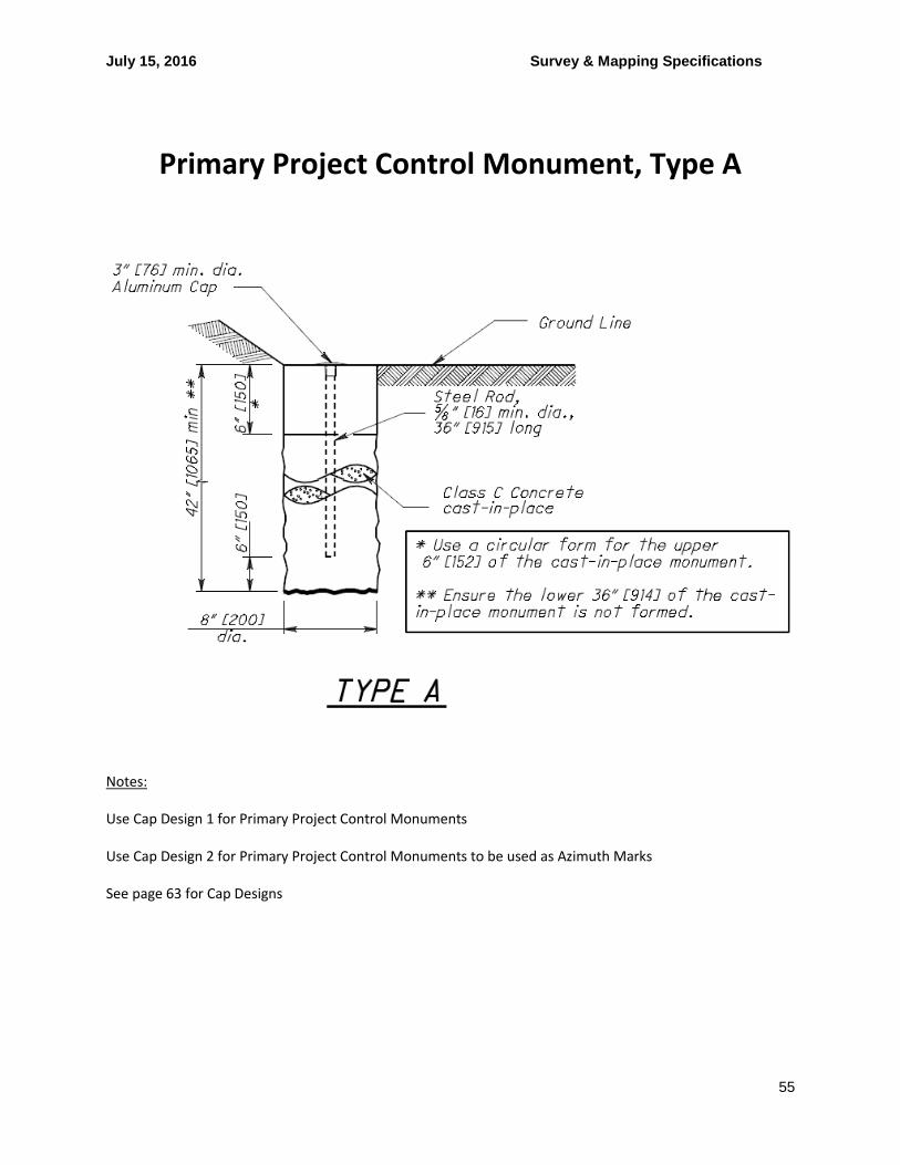
July 15, 2016 Survey & Mapping Specifications
55
Primary Project Control Monument, Type A
Notes:
Use Cap Design 1 for Primary Project Control Monuments
Use Cap Design 2 for Primary Project Control Monuments to be used as Azimuth Marks
See page 63 for Cap Designs
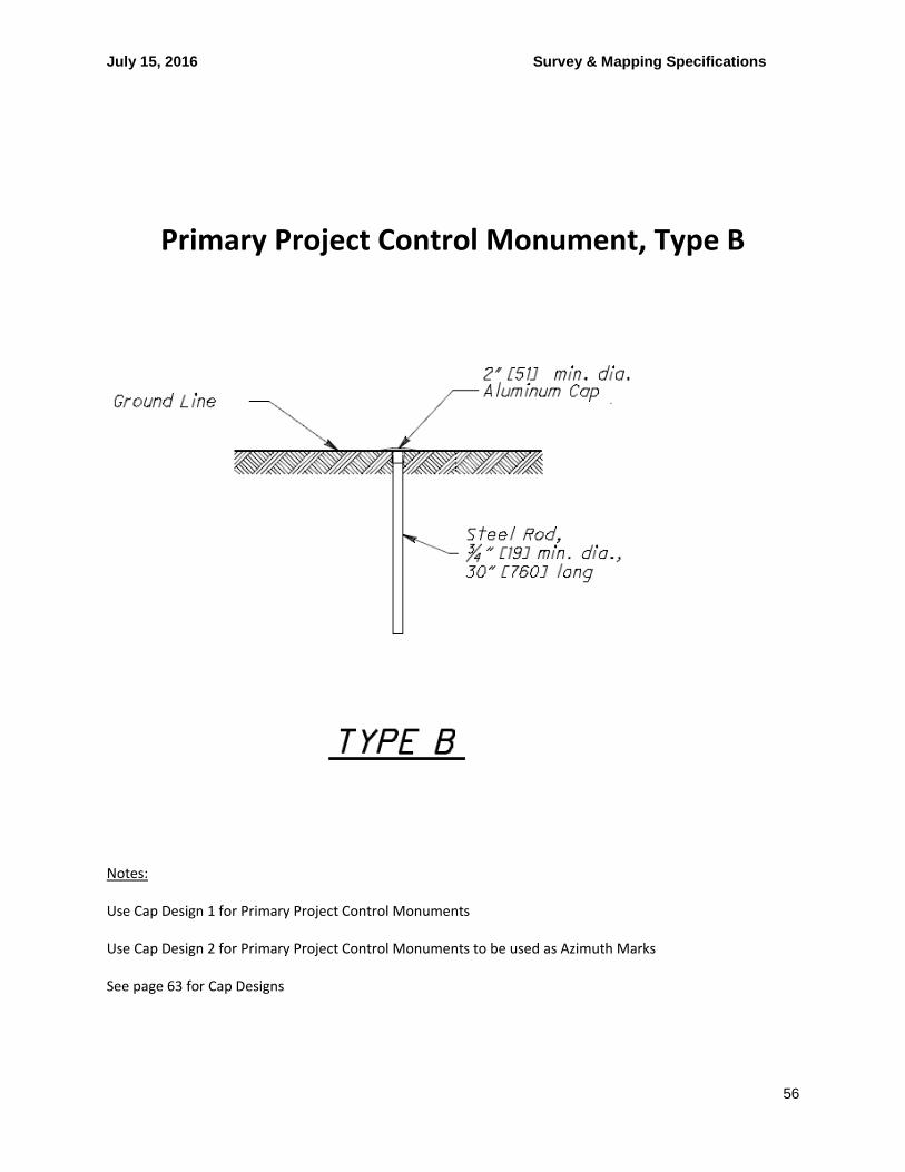
July 15, 2016 Survey & Mapping Specifications
56
Primary Project Control Monument, Type B
Notes:
Use Cap Design 1 for Primary Project Control Monuments
Use Cap Design 2 for Primary Project Control Monuments to be used as Azimuth Marks
See page 63 for Cap Designs

July 15, 2016 Survey & Mapping Specifications
57
Cap Designs

July 15, 2016 Survey & Mapping Specifications
58
Appendix J – L & D Manual G105 Survey Parameters

July 15, 2016 Survey & Mapping Specifications
59
Appendix B
Sample Plan Note – G105
G105 – SURVEYING PARAMETERS Designer Note: Use note G105, unless otherwise directed by the District Survey Operations Manager. Projects should have utilized the Department’s Survey and Mapping Specification which can be found on the Office of CADD and Mapping Services’ website. Specify primary project control parameters and provide a table in the plans with the following information for primary project control monuments, including azimuth marks and temporary benchmarks: Point Number, Grid Coordinates (Northing, Easting), Scaled Coordinates (Northing, Easting), Elevation, and Description of Monument. At a minimum, the Description of Monument in the table shall indicate the type of monument (i.e. iron pin, concrete monument, etc.) and whether the monument is for project control or traverse purposes. If a Monument, Type B, is used for project control, do not provide an elevation in the Elevation column of the table. Use of a Monument, Type B, establishes horizontal control only. A separate vertical benchmark (i.e. aluminum disc on bridge abutment) will need to be included in the table. Project control is typically established prior to construction. If the designer determines that the location of the monuments associated with project control may be disturbed by the Contractor’s construction activities, provide quantities for resetting the monuments in the plans according to CMS 623. Standard Construction Drawing RM-1.1 and the Department’s Survey and Mapping Specification provide further information regarding project control. G105 PRIMARY PROJECT CONTROL MONUMENTS GOVERN ALL POSITIONING ON ODOT PROJECTS. SEE SHEET ___ OF THE PLANS FOR A TABLE CONTAINING PROJECT CONTROL INFORMATION. USE THE FOLLOWING PROJECT CONTROL, VERTICAL POSITIONING, AND HORIZONTAL POSITIONING PARAMETERS FOR ALL SURVEYING: PROJECT CONTROL POSITIONING METHOD: ____________________________
MONUMENT TYPE: ____________________________ VERTICAL POSITIONING ORTHOMETRIC HEIGHT DATUM: ____________________________
GEOID: ____________________________ HORIZONTAL POSITIONING REFERENCE FRAME: ____________________________
ELLIPSOID: ____________________________
MAP PROJECTION: ____________________________
COORDINATE SYSTEM: ____________________________
COMBINED SCALE FACTOR: ____________________________
ORIGIN OF COORDINATE
SYSTEM: ____________________________ USE THE POSITIONING METHODS AND MONUMENT TYPE USED IN THE ORIGINAL SURVEY TO RESTORE ALL MONUMENTS RELATED TO PRIMARY PROJECT CONTROL THAT ARE DAMAGED OR DESTROYED BY CONSTRUCTION ACTIVITIES. RESTORE THE DAMAGED OR DESTROYED MONUMENTS IN ACCORDANCE WITH CMS 623.

July 15, 2016 Survey & Mapping Specifications
60
Appendix H – Project Scale Factor Calculations
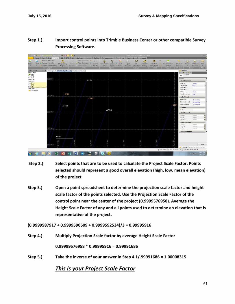
July 15, 2016 Survey & Mapping Specifications
61
Step 1.) Import control points into Trimble Business Center or other compatible Survey
Processing Software.
Step 2.) Select points that are to be used to calculate the Project Scale Factor. Points
selected should represent a good overall elevation (high, low, mean elevation)
of the project.
Step 3.) Open a point spreadsheet to determine the projection scale factor and height
scale factor of the points selected. Use the Projection Scale Factor of the
control point near the center of the project (0.9999576958). Average the
Height Scale Factor of any and all points used to determine an elevation that is
representative of the project.
(0.9999587917 + 0.9999590609 + 0.9999592534)/3 = 0.99995916
Step 4.) Multiply Projection Scale factor by average Height Scale Factor
0.99999576958 * 0.99995916 = 0.99991686
Step 5.) Take the inverse of your answer in Step 4 1/.99991686 = 1.00008315
This is your Project Scale Factor

July 15, 2016 Survey & Mapping Specifications
62
Step 6.) Select Local Site Settings to enter the Project Scale Factor and project the site
to Ground Coordinates
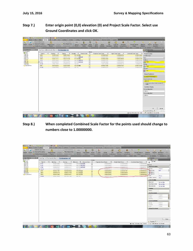
July 15, 2016 Survey & Mapping Specifications
63
Step 7.) Enter origin point (0,0) elevation (0) and Project Scale Factor. Select use
Ground Coordinates and click OK.
Step 8.) When completed Combined Scale Factor for the points used should change to
numbers close to 1.00000000.