survey of contemporary adls - home - springer978-0-387-26399-1/1.pdf · a survey of contemporary...
TRANSCRIPT
ASURVEY OF CONTEMPORARY ADLS
Section 2.1 presented an overview of ADLs. Figure 2.2 shows the classificationof ADLs based on two aspects: content and objective. The content-oriented clas-sification is based on the nature of the information an ADL can capture, whereasthe objective-oriented classification is based on the purpose of an ADL. This ap-pendix presents a survey using content-based classification of ADLs. There aremany comprehensive ADL surveys available in the literature including ADLs forretargetable compilation by Qin et al. [137], ADLs for programmable embeddedsystems by Mishra et al. [101], and ADLs for SOC design by Tomiyama et al.[38].
A.I Structural ADLs
The structural ADLs capture the structure in terms of architectural components andtheir connectivity. Early ADLs are based on register-transfer level descriptions:lower abstraction level to enable detailed modeling of digital systems. This sectionbriefly describes two structural ADLs: MIMOLA [117] and UDL/I [34].
MIMOLA
MIMOLA [117] is a structure-centric ADL developed at the University of Dort-mund, Germany. It was originally proposed for micro-architecture design. Oneof the major advantages of MIMOLA is that the same description can be used forsynthesis, simulation, test generation, and compilation. A tool chain including theMSSH hardware synthesizer, the MSSQ code generator, the MSST self-test pro-gram compiler, the MSSB functional simulator, and the MSSU RT-level simulatorwere developed based on the MIMOLA language [117]. MIMOLA has also beenused by the RECORD [116] compiler.

128 APPENDIX A. SURVEY OF CONTEMPORARY ADLS
MIMOLA description contains three parts: the algorithm to be compiled, thetarget processor model, and additional linkage and transformation rules. The soft-ware part (algorithm description) describes application programs in a PASCAL-like syntax. The processor model describes micro-architecture in the form of acomponent netlist. The linkage information is used by the compiler in order tolocate important modules such as program counter and instruction memory. Thefollowing code segment specifies the program counter and instruction memory lo-cations [117]:
LOCATION_FOR_PROGRAMCOUNTER PCReg;LOCATION FOR INSTRUCTIONS IM[O..1O23];
The algorithmic part of MIMOLA is an extension of PASCAL. Unlike otherhigh level languages, it allows references to physical registers and memories. Italso allows use of hardware components using procedure calls. For example, if theprocessor description contains a component named MAC, programmers can writethe following code segment to use the multiply-accumulate operation performedby MAC:
r e s := MAC(x, y, z)
The processor is modeled as a net-list of component modules. MIMOLA per-mits modeling of arbitrary (programmable or non-programmable) hardware struc-tures. Similar to VHDL, a number of predefined, primitive operators exists. Thebasic entities of MIMOLA hardware models are modules and connections. Eachmodule is specified by its port interface and its behavior. The following exampleshows the description of a multi-functional ALU module [117]:
MODULE ALU(IN inplOUT outp:IN Ctrl
)CONBEGIN
outp
CONEND;
:
<0:1:2 :3 :
inp2 :(31:
(1:0)
(31:0);0) ;
:- CASE Ctrl OFinplinplinplinpl
END;
+ inp2 ;- inp2 ;AND inp2 ;;
A.L STRUCTURALADLS 129
The CONBEGIN/CONEND construct includes a set of concurrent assignments.In the example a conditional assignment to output port outp is specified, which de-pends on the two-bit control input Ctrl. The netlist structure is formed by connect-ing ports of module instances. For example, the following MIMOLA descriptionconnects two modules: ALU and accumulator ACC.
CONNECTIONS ALU.outp -> ACC.inpACC.outp -> ALU.inp
The MSSQ code generator extracts instruction-set information from the mod-ule netlist. It uses two internal data structures: connection operation graph (COG)and instruction tree (I-tree). It is a very difficult task to extract the COG and I-treeseven in the presence of linkage information due to the flexibility of an RT-levelstructural description. Extra constraints need to be imposed in order for the MSSQcode generator to work properly. The constraints limit the architecture scope ofMSSQ to micro-programmable controllers, in which all control signals originatedirectly from the instruction word. The lack of explicit description of processorpipelines or resource conflicts may result in poor code quality for some classes ofVLIW or deeply pipelined processors.
UDL/I
Unified design language, UDL/I is [34] developed as a hardware description lan-guage for compiler generation in COACH ASIP design environment at KyushuUniversity, Japan. UDL/I is used for describing processors at an RT-level on aper-cycle basis. The instruction-set is automatically extracted from the UDL/I de-scription [35], and then it is used for generation of a compiler and a simulator.COACH assumes simple RISC processors and does not explicitly support ILP orprocessor pipelines. The processor description is synthesizable with the UDL/Isynthesis system [39]. The major advantage of the COACH system is that it re-quires a single description for synthesis, simulation, and compilation. Designerneeds to provide hints to locate important machine states such as program counterand register files. Due to difficulty in instruction-set extraction (ISE), ISE is notsupported for VLIW and superscalar architectures.
Structural ADLs enable flexible and precise micro-architecture descriptions.The same description can be used for hardware synthesis, test generation, simu-lation and compilation. However, it is difficult to extract instruction-set withoutrestrictions on description style and target scope. Structural ADLs are more suit-able for hardware generation than retargetable compilation.

130 APPENDIX A. SURVEY OF CONTEMPORARY ADLS
A.2 Behavioral ADLs
The difficulty of instruction-set extraction can be avoided by abstracting behavioralinformation from the structural details. Behavioral ADLs explicitly specify theinstruction semantics and ignore detailed hardware structures. Typically, there is aone-to-one correspondence between behavioral ADLs and instruction-set referencemanual. This section briefly describes three behavioral ADLs: nML [72], ISDL[31]andValen-C[6].
nML
nML is an instruction-set oriented ADL proposed at Technical University of Berlin.nML has been used by code generators CBC [3] and CHESS [22], and instruction-set simulators Sigh/Sim [28] and CHECKERS. Currently, CHESS/CHECKERSenvironment is used for automatic and efficient software compilation and instruction-set simulation [49].
nML developers recognized the fact that several instructions share commonproperties. The final nML description would be compact and simple if the com-mon properties are exploited. Consequently, nML designers used a hierarchicalscheme to describe instruction-set. The instructions are the topmost elements inthe hierarchy. The intermediate elements of the hierarchy are partial instructions(PI). The relationship between elements can be established using two compositionrules: AND-rule and OR-rule. The AND-rule groups several Pis into a larger PIand the OR-rule enumerates a set of alternatives for one PI. Therefore instructiondefinitions in nML can be in the form of an and-or tree. Each possible derivationof the tree corresponds to an actual instruction.
To achieve the goal of sharing instruction descriptions, the instruction-set isenumerated by an attribute grammar [60]. Each element in the hierarchy has afew attributes. A non-leaf element's attribute values can be computed based on itschildren's attribute values. Attribute grammar is also adopted by other ADLs suchas ISDL [31] and TDL [21].
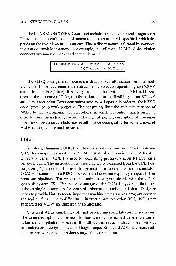
The following nML description shows an example of instruction specification[72]: The definition of numeric-instruction combines three partial instructions (PI)with the AND-rule: nunuaction, SRC, and DST. The first PI, num_action, usesOR-rule to describe the valid options for actions: add or sub. The number of allpossible derivations ofnumeric-instruction is the product of the size oinumMction,SRC and DST. The common behavior of all these options is defined in the actionattribute of numeric-instruction. Each option for num-action should have its ownaction attribute defined as its specific behavior, which is referred by the a.actionline. For example, the following code segment has action description for add op-
A.2. BEHAVIORAL ADLS 131
eration. Object code image and assembly syntax can also be specified in the samehierarchical manner.
op numericonstruction (a:num_action/ src:SRC, dst:DST)action {
temp_src = src;temp_dst = dst;a.action;dst = temp_dst;
}op num_action = add | subop add()action = {
temp_dst = temp_dst + temp_src}
nML also captures the structural information used by instruction-set architec-ture (ISA). For example, storage units should be declared since they are visible tothe instruction-set. nML supports three types of storages: RAM, register, and tran-sitory storage. Transitory storage refers to machine states that are retained only fora limited number of cycles e.g., values on buses and latches. Computations haveno delay in nML timing model - only storage units have delay. Instruction delayslots are modeled by introducing storage units as pipeline registers. The result ofthe computation is propagated through the registers in the behavior specification.
nML models constraints between operations by enumerating all valid com-binations. The enumeration of valid cases can make nML descriptions lengthy.More complicated constraints, which often appear in DSPs with irregular instruc-tion level parallelism (ILP) constraints or VLIW processors with multiple issueslots, are hard to model with nML. For example, nML cannot model the constraintthat operation II cannot directly follow operation 10. nML explicitly supports sev-eral addressing modes. However, it implicitly assumes an architecture model whichrestricts its generality. As a result it is hard to model multi-cycle or pipelined unitsand multi-word instructions explicitly. A good critique of nML is given in [73].
ISDL
Instruction Set Description Language (ISDL) was developed at MIT and used bythe Aviv compiler [120] and GENSIM simulator generator [30]. The problem ofconstraint modeling is avoided by ISDL with explicit specification. ISDL is mainlytargeted towards VLIW processors. Similar to nML, ISDL primarily describes theinstruction-set of processor architectures. ISDL consists of mainly five sections:

132 APPENDIX A. SURVEY OF CONTEMPORARY ADLS
instruction word format, global definitions, storage resources, assembly syntax,and constraints. It also contains an optimization information section that can beused to provide certain architecture specific hints for the compiler to make bettermachine dependent code optimizations.
The instruction word format section defines fields of the instruction word. Theinstruction word is separated into multiple fields each containing one or moresubfields. The global definition section describes four main types: tokens, non-terminals, split functions and macro definitions. Tokens are the primitive operandsof instructions. For each token, assembly format and binary encoding informationmust be defined. An example token definition of a binary operand is:
Token X[O..l] X_R ival {yylval.ival = yytext[1] - '0';}
In this example, following the keyword Token is the assembly format of theoperand. X_R is the symbolic name of the token used for reference. The ival isused to describe the value returned by the token. Finally, the last field describesthe computation of the value. In this example, the assembly syntax allowed for thetoken X-R is X0 or XI, and the values returned are 0 or 1 respectively.
The value (last) field is to be used for behavioral definition and binary encod-ing assignment by non-terminals or instructions. Non-terminal is a mechanismprovided to exploit commonalities among operations. The following code segmentdescribes a non-terminal named XYSRC:
Nonterminal ival XYSRC: X_D {$$ = 0;} |Y_D {$$ = Y_D + 1;};
The definition of XYSRC consists of the keyword Nonterminal, the type ofthe returned value, a symbolic name as it appears in the assembly, and an actionthat describes the possible token or non-terminal combinations and the return valueassociated with each of them. In this example, XYSRC refers to tokens XJ) andYS> as its two options. The second field (ival) describes the returned value type. Itreturns 0 fovXJ) or incremented value for YJD.
Similar to nML, storage resources are the only structural information modeledby ISDL. The storage section lists all storage resources visible to the programmer.It lists the names and sizes of the memory, register files, and special registers. Thisinformation is used by the compiler to determine the available resources and howthey should be used.
The assembly syntax section is divided into fields corresponding to the separateoperations that can be performed in parallel within a single instruction. For each

A.2. BEHAVIORAL ADLS 133
field, a list of alternative operations can be described. Each operation descriptionconsists of a name, a list of tokens or non-terminals as parameters, a set of com-mands that manipulate the bitfields, RTL description, timing details, and costs.RTL description captures the effect of the operation on the storage resources. Mul-tiple costs are allowed including operation execution time, code size, and costs dueto resource conflicts. The timing model of ISDL describes when the various effectsof the operation take place.
In contrast to nML, which enumerates all valid combinations, ISDL defines in-valid combinations in the form of Boolean expressions. This often leads to a simpleconstraint specification. It also enables ISDL to capture irregular ILP constraints.The following example shows how to describe the constraint that instruction IIcannot directly follow instruction 10. The "[1]" indicates a time shift of one in-struction fetch for the 10 instruction. The '~' is a symbol for NOT and '&' is forlogical AND.
| ~ ( i i *) & ( [ l ] io *, * ) |
ISDL provides the means for compact and hierarchical instruction-set specifi-cation. However, it may not be possible to describe a instruction-set with multipleencoding formats using simple tree-like instruction structure of ISDL.
Valen-C
Valen-C is an embedded software programming language proposed at KyushuUniversity, Japan [6, 7]. Valen-C is an extended C language which supports ex-plicit and exact bit-width for integer type declarations. A retargetable compiler(called Valen-CC) has been developed that accepts C or Valen-C programs as aninput and generates the optimized assembly code. Although Valen-CC assumessimple RISC architectures, it has retargetability to some extent. The most interest-ing feature of Valen-CC is that the processor can have any datapath bit-width (e.g.,14 bits or 29 bits). The Valen-C system aims at optimization of datapath width.The target processor description for Valen-CC includes the instruction-set consist-ing of behavior and assembly syntax of each instruction as well as the processordatapath width. Valen-CC does not explicitly support processor pipelines or ILP.
In general, the behavioral languages have one feature in common: hierarchicalinstruction-set description based on attribute grammar [60]. This feature simplifiesthe instruction-set description by sharing the common components between oper-ations. However, the capabilities of these models are limited due to the lack ofdetailed pipeline and timing information. It is not possible to generate cycle ac-curate simulators without certain assumptions regarding control behavior. Due to
134 APPENDIX A. SURVEY OF CONTEMPORARY ADLS
lack of structural details, it is also not possible to perform resource-based schedul-ing using behavioral ADLs.
A.3 Mixed ADLs
Mixed languages captures both structural and behavioral details of the architecture.This section briefly describes four mixed ADLs: Flex Ware, HMDES, EXPRES-SION, and LISA.
FlexWare
Flex Ware is a CAD system for DSP or ASIP design [108]. The FlexWare systemincludes the CodeSyn code generator and the Insulin simulator. Both behavior andstructure are captured in the target processor description. The machine descriptionfor CodeSyn consists of three components: instruction-set, available resources (andtheir classification), and an interconnect graph representing the datapath structure.The instruction-set description is a list of generic processor macro instructions toexecute each target processor instruction. The simulator uses a VHDL model ofa generic parameterizable machine. The parameters include bit-width, number ofregisters, ALUs, and so on. The application is translated from the user-definedtarget instruction-set to the instruction-set of the generic machine. Then, the codeis executed on the generic machine.
HMDES
Machine description language HMDES was developed at University of Illinois atUrbana-Champaign for the IMPACT research compiler [54]. C-like preprocess-ing capabilities such as file inclusion, macro expansion and conditional inclusionare supported in HMDES. An HMDES description is the input to the MDES ma-chine description system of the Trimaran compiler infrastructure, which containsIMPACT as well as the Elcor research compiler from HP Labs. The descriptionis first pre-processed, then optimized and translated to a low-level representationfile. A machine database reads the low level files and supplies information for thecompiler back end through a predefined query interface.
MDES captures both structure and behavior of target processors. Informationis broken down into sections such as format, resource usage, latency, operation, andregister. For example, the following code segment describes register and registerfile. It describes 64 registers. The register file describes the width of each registerand other optional fields such as generic register type (virtual field), speculative,

A3. MIXED ADLS 135
static and rotating registers. The value T implies speculative and '0 ' implies non-speculative.
SECTION Register {R0() ; Rl() ; ... R63() ;'R[0] ' 0 ; ... 'R[63] ' (
SECTION Register_ File {RF_i(width(32) virtual(i) speculative(1)
static(R0. . .R63) rotating('R[0] ' . . .'R [63] ')) ;
MDES allows only a restricted retargetability of the cycle-accurate simulator tothe HPL-PD processor family [80]. MDES permits description of memory systems,but limited to the traditional hierarchy, i.e., register files, caches, and main memory.
EXPRESSION
The above mixed ADLs require explicit description of Reservation Tables (RT).Processors that contain complex pipelines, large amounts of parallelism, and com-plex storage sub-systems, typically contain a large number of operations and re-sources (and hence RTs). Manual specification of RTs on a per-operation basisthus becomes cumbersome and error-prone. The manual specification of RTs (foreach configuration) becomes impractical during rapid architectural exploration.The EXPRESSION ADL [5] describes a processor as a netlist of units and stor-ages to automatically generate RTs based on the netlist [88]. Unlike MIMOLA,the netlist representation of EXPRESSION is coarse grain. It uses a higher level ofabstraction similar to block-diagram level description in architecture manual.
EXPRESSION ADL was developed at University of California, Irvine. TheADL has been used by the retargetable compiler (EXPRESS [4]) and simulator(SIMPRESS [8]) generation framework. The framework also supports a graphicaluser interface (GUI) and can be used for design space exploration of programmablearchitectures consisting of processor cores, coprocessors and memories [45].
An EXPRESSION description is composed of two main sections: behavior(instruction-set), and structure. The behavior section has three subsections: opera-tions, instruction, and operation mappings. Similarly, the structure section consistsof three subsections: components, pipeline/data-transfer paths, and memory sub-system.

136 APPENDIX A. SURVEY OF CONTEMPORARY ADLS
The operation subsection describes the instruction-set of the processor. Eachoperation of the processor is described in terms of its opcode and operands. Thetypes and possible destinations of each operand are also specified. A useful featureof EXPRESSION is operation group that groups similar operations together forthe ease of later reference. For example, the following code segment shows anoperation group {alu-ops) containing two ALU operations: add and sub.
(OP_GROUP alu_ops(OPCODE add
(OPERANDS(BEHAVIOR
(OPCODE sub(OPERANDS(BEHAVIOR
(SRC1DEST
(SRC1DEST
reg)= SRC1
reg)= SRC1
(SRC2 reg/imm)+ SRC2)
(SRC2 reg/imm)- SRC2)
(DEST
(DEST
reg) )
reg) )
The instruction subsection captures the parallelism available in the architecture.Each instruction contains a list of slots (to be filled with operations), with each slotcorresponding to a functional unit. The operation mapping subsection is used tospecify the information needed by instruction selection and architecture-specificoptimizations of the compiler. For example, it contains mapping between genericand target instructions.
The component subsection describes each RT-level component in the architec-ture. The components can be pipeline units, functional units, storage elements,ports, and connections. For multi-cycle or pipelined units, the timing behavior isalso specified.
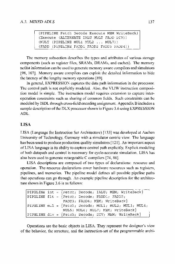
The pipeline/data-transfer path subsection describes the netlist of the proces-sor. The pipeline path description provides a mechanism to specify the units whichcomprise the pipeline stages, while the data-transfer path description provides amechanism for specifying the valid data-transfers. This information is used to bothretarget the simulator, and to generate reservation tables needed by the scheduler[88]. An example path declaration for the DLX architecture [55] (Figure 3.6) isshown below. It describes that the processor has five pipeline stages. It also de-scribes that the Execute stage has four parallel paths. Finally, it describes each pathe.g., it describes that the FADD path has four pipeline stages.
A3. MIXED ADLS 137
(PIPELINE Fetch Decode Execute MEM WriteBack)(Execute (ALTERNATE IALU MULT FADD DIV))(MULT (PIPELINE MUL1 MUL2 ... MUL7))(FADD (PIPELINE FADD1 FADD2 FADD3 FADD4))
The memory subsection describes the types and attributes of various storagecomponents (such as register files, SRAMs, DRAMs, and caches). The memorynetlist information can be used to generate memory aware compilers and simulators[98, 107]. Memory aware compilers can exploit the detailed information to hidethe latency of the lengthy memory operations [89].
In general, EXPRESSION captures the data path information in the processor.The control path is not explicitly modeled. Also, the VLIW instruction composi-tion model is simple. The instruction model requires extension to capture inter-operation constraints such as sharing of common fields. Such constraints can bemodeled by I SDL through cross-field encoding assignment. Appendix B includes asample description of the DLX processor shown in Figure 3.6 using EXPRESSIONADL.
LISA
LISA (Language for Instruction Set Architecture) [133] was developed at AachenUniversity of Technology, Germany with a simulator centric view. The languagehas been used to produce production quality simulators [121]. An important aspectof LISA language is its ability to capture control path explicitly. Explicit modelingof both datapath and control is necessary for cycle-accurate simulation. LISA hasalso been used to generate retargetable C compilers [74, 86].
LISA descriptions are composed of two types of declarations: resource andoperation. The resource declarations cover hardware resources such as registers,pipelines, and memories. The pipeline model defines all possible pipeline pathsthat operations can go through. An example pipeline description for the architec-ture shown in Figure 3.6 is as follows:
PIPELINEPIPELINE
PIPELINE
PIPELINE
int =fit =
mul =
div =
{Fetch;{Fetch;FADD3;{Fetch;MUL 5 ;{Fetch;
Decode;Decode;FADD4;Decode;
IALU; MEM; WriteBack}FADD1; FADD2;
MEM; WriteBack}MUL1; MUL2; MUL3; MUL4;
MUL6; MUL7; MEM; WriteBack}Decode; DIV; MEM; WriteBack}
Operations are the basic objects in LISA. They represent the designer's viewof the behavior, the structure, and the instruction-set of the programmable archi-
138 APPENDIX A. SURVEY OF CONTEMPORARY ADLS
tecture. Operation definitions capture the description of different properties of thesystem such as operation behavior, instruction-set information, and timing. Theseoperation attributes are defined in several sections:
• The CODING section describes the binary image of the instruction word.
• The SYNTAX section describes the assembly syntax of instructions.
• The SEMANTICS section specifies the instruction-set semantics.
• The BEHAVIOR section describes components of the behavioral model.
• The ACTIVATION section describes the timing of other operations relativeto the current operation.
• The DECLARE section contains local declarations of identifiers.
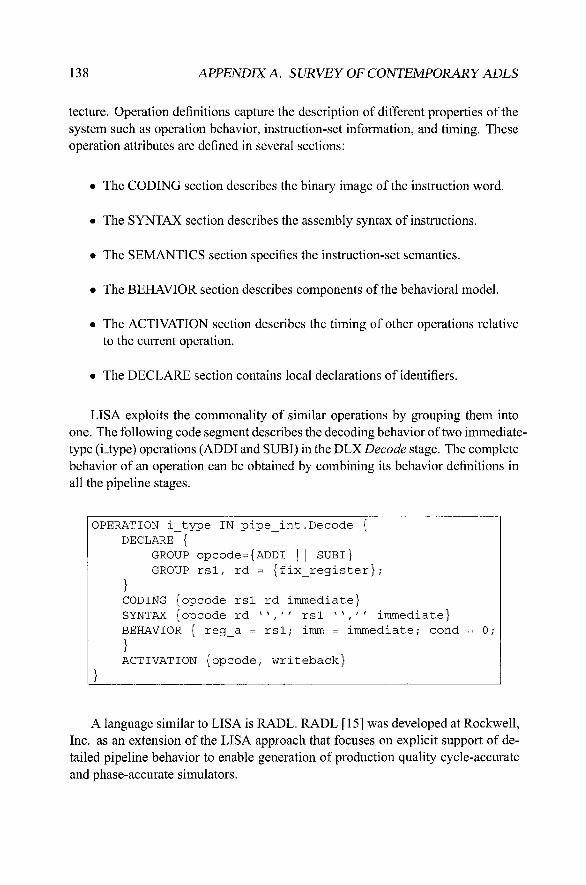
LISA exploits the commonality of similar operations by grouping them intoone. The following code segment describes the decoding behavior of two immediate-type (Ltype) operations (ADDI and SUBI) in the DLX Decode stage. The completebehavior of an operation can be obtained by combining its behavior definitions inall the pipeline stages.
OPERATION i_type IN pipe_int.Decode {DECLARE {
GROUP opcode={ADDI || SUBl}GROUP rsl, rd = {fix_register};
}CODING {opcode rsl rd immediate}SYNTAX {opcode rd y\" rsl x \ " immediate}BEHAVIOR { reg_a = rsl; imm = immediate; cond = 0;}ACTIVATION {opcode, writeback}
A language similar to LISA is RADL. RADL [15] was developed at Rockwell,Inc. as an extension of the LISA approach that focuses on explicit support of de-tailed pipeline behavior to enable generation of production quality cycle-accurateand phase-accurate simulators.

A A. PARTIAL ADLS 139
A.4 Partial ADLs
The ADLs discussed so far captures complete description of the processor's struc-ture, behavior or both. There are many description languages that captures partialinformation of the architecture needed to perform a specific task. This sectiondescribes two such ADLs.
AIDL
AIDL is an ADL developed at University of Tsukuba for design of high-performancesuperscalar processors [129]. AIDL aims at validation of the pipeline behaviorsuch as data-forwarding and out-of-order completion. In AIDL, timing behaviorof pipeline is described using interval temporal logic. AIDL does not support soft-ware toolkit generation. However, AIDL descriptions can be simulated using theAIDL simulator.
PEAS-I
PEAS-I is a CAD system for ASIP design supporting automatic instruction-set op-timization, compiler generation, and instruction level simulator generation [61]. Inthe PEAS-I system, the GNU C compiler is used, and the machine description ofGCC is automatically generated. Inputs to PEAS-I include an application programwritten in C and input data to the program. Then, the instruction-set is automati-cally selected in such a way that the performance is maximized or the gate countis minimized. Based on the instruction-set, GNU CC and an instruction level sim-ulator is automatically retargeted.

BSPECIFICATION OF DLX PROCESSOR
This appendix includes a sample description of the DLX processor shown in Fig-ure 3.6 using EXPRESSION ADL.
This machine description is copyrighted by the Regents of the *University of California, Irvine. This is a simplified version*of the EXPRESSION description for the DLX processor. It only *includes the features that are required for the validation *steps discussed in this book. No Warranty of any kind. *
*************** Section 1: Specific Operations ***•
(OPERATIONS_SECTION
(OP_GROUP all(OPCODE IADD
(OP_TYPE DATA_OP)(OPERANDS (DEST reg) (SRC1 reg) (SRC2 reg/imm))(BEHAVIOR DEST = SRC1 + SRC2)
(OPCODE ISUB(OP_TYPE DATA_OP)(OPERANDS (DEST reg) (SRC1 reg) (SRC2 reg/imm)](BEHAVIOR DEST = SRC1 - SRC2)
(OPCODE IMUL(OP_TYPE DATA_OP)(OPERANDS (DEST reg) (SRC1 reg) (SRC2 reg/imm) ;(BEHAVIOR DEST = SRC1 * SRC2)

142 APPENDIX B. SPECIFICATION OF DLX PROCESSOR
(OPCODE IDIV(OP_TYPE DATA_OP)(OPERANDS (DEST reg) (SRC1 reg) (SRC2 reg/imm))(BEHAVIOR DEST = SRC1 / SRC2)
(OPCODE ILSH(OP_TYPE DATA_OP)(OPERANDS (DEST reg) (SRC1 reg) (SRC2 imm);(BEHAVIOR DEST = SRC1 << SRC2)
(OPCODE ILT(OP_TYPE DATA_OP)(OPERANDS (DEST reg) (SRC1 reg) (SRC2 reg/imm))(BEHAVIOR DEST = (SRC1 < SRC2) ? 1 : 0)
(OPCODE IVLOAD(OP_TYPE DATA_OP)(OPERANDS (DEST reg) (SRC1 reg) (SRC2 imm)(BEHAVIOR DEST = MEMORY[SRC1 + SRC2])
(OPCODE IVSTORE(OP_TYPE DATA_OP)(OPERANDS (SRC reg) (SRC1 reg) (SRC2 imm))(BEHAVIOR MEMORY[SRC1 + SRC2] = SRC)
(OPCODE BEQZ(OP_TYPE CONTROL_OP)(OPERANDS (SRC1 reg) (SRC2 imm))(BEHAVIOR PC = (SRC1 == 0) ? SRC2 : PC + 4)
(OPCODE J(OP_TYPE CONTROL_OP)(OPERANDS (SRC reg/imm))(BEHAVIOR PC = SRC)

143
(OP_GROUP ALU_instr(OPCODE ICONSTANT IASSIGN ASSIGN IADD ISUB ILSH IASH IVLOAD
DVLOAD FVLOAD IVSTORE DVSTORE FVSTORE ILAND IEQ INEILE IGE ILT IGT J BEQZ BNEZ NOP
(OP_GROUP MUL_instr(OPCODE IMUL DMUL FMUL NOP)
(OP_GROUP FADD_instr(OPCODE DCONSTANT FCONSTANT DASSIGN FASSIGN DADD FADD DSUB FSUB
DEQ FEQ DNE FNE DLE FLE DGE FGE DLT FLT DGT FGT CVTDI CVTSICVTSD CVTDS DMTC1 DMFC1 DNEG MFC1 MTC1 TRUNCID TRUNCIS NOP
(OP_GROUP FDIV_instr(OPCODE IDIV DDIV FDIV NOP)
(OP_GROUP LDST_instr(OPCODE IVLOAD DVLOAD FVLOAD IVSTORE DVSTORE FVSTORE)
Section 2: Instruction template
(INSTRUCTION_SECTION(WORDLEN 32)(SLOTS((TYPE DATA)( (TYPE DATA)((TYPE DATA)( (TYPE DATA)
(BITWIDTH 8)(BITWIDTH 8)(BITWIDTH 8)(BITWIDTH 8)
(UNIT IALU) !(UNIT MUL))(UNIT FADD) ;(UNIT FDIV) ;
; (TYPE CONTROL) (BITWIDTH 8) (UNIT DECODE))
Section 3: Operation Mappings
(OPMAPPING SECTION
(GENERIC ((IMUL tmpDest SRC1 SRC2) (IADD DEST tmpDest SRC3)))(TARGET (MAC DEST SRC1 SRC2 SRC3))

144 APPENDIX B. SPECIFICATION OF DLX PROCESSOR
Section 4: Components Specification
(ARCHITECTURE_SECTION(SUBTYPE UNIT FetchUnit DecodeUnit IAluUnit FMulUnit FAddUnit
FDivUnit MemoryUnit WriteBackUnit)(SUBTYPE PORT UnitPort Port)(SUBTYPE CONNECTION MemoryConnection RegConnection)(SUBTYPE STORAGE VirtualRegFile VirtualMemory)(SUBTYPE LATCH PipelineLatch MemoryLatch)
(FetchUnit FETCH(CAPACITY 1) (TIMING (all 1)) (OPCODES all)(LATCHES (OUT FetDecLatch) (IN PCLatch))
(DecodeUnit DECODE(CAPACITY 1) (TIMING (all 1)) (OPCODES all)(LATCHES (IN FetDecLatch) (OUT DecALULatch DecMlLatch
DecAlLatch DecFDivLatch))(PORTS DecRdPortl DecRdPort2)
(IntAluUnit IALU(CAPACITY 1) (TIMING (all 1)) (OPCODES ALU_instr)(LATCHES (IN DecIALULatch) (OUT ExMemLatch))
(FMultUnit Ml(CAPACITY 1) (TIMING (all 1)) (OPCODES MUL_instr)(LATCHES (IN DecMlLatch) (OUT MlM2Latch))
(FAddUnit Al(CAPACITY 1) (TIMING (all 1)) (OPCODES FADD_instr)(LATCHES (IN DecAlLatch) (OUT AlA2Latch))
(FDivUnit FDIV(CAPACITY 1) (OPCODES FDIV_instr)(TIMING (IDIV 25) (FDIV 25) (DDIV 25) (NOP 1))(LATCHES (IN DecFDivLatch) (OUT ExMemLatch))
(FMultUnit M2(CAPACITY 1) (TIMING (all 1)) (OPCODES MUL_instr)(LATCHES (IN MlM2Latch) (OUT M2M3Latch))
145
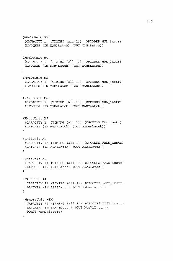
(FMultUnit M3(CAPACITY 1) (TIMING (all 1)) (OPCODES MUL_instr)(LATCHES (IN M2M3Latch) (OUT M3M4Latch))
(FMultUnit M4(CAPACITY 1) (TIMING (all 1)) (OPCODES MUL_instr)(LATCHES (IN M3M4Latch) (OUT M4M5Latch))
(FMultUnit M5(CAPACITY 1) (TIMING (all 1)) (OPCODES MUL_instr)(LATCHES (IN M4M5Latch) (OUT M5M6Latch))
(FMultUnit M6(CAPACITY 1) (TIMING (all 1)) (OPCODES MUL_instr)(LATCHES (IN M5M6Latch) (OUT M6M7Latch))
(FMultUnit M7(CAPACITY 1) (TIMING (all 1)) (OPCODES MUL_instr)(LATCHES (IN M6M7Latch) (OUT ExMemLatch))
(FAddUnit A2(CAPACITY 1) (TIMING (all 1)) (OPCODES FADD_instr)(LATCHES (IN AlA2Latch) (OUT A2A3Latch))
(FAddUnit A3(CAPACITY 1) (TIMING (all 1)) (OPCODES FADD_instr)(LATCHES (IN A2A3Latch) (OUT A3A4Latch))
(FAddUnit A4(CAPACITY 1) (TIMING (all 1)) (OPCODES FADD_instr)(LATCHES (IN A3A4Latch) (OUT ExMemLatch))
(MemoryUnit MEM(CAPACITY 1) (TIMING (all 1)) (OPCODES LDST_instr)(LATCHES (IN ExMemLatch) (OUT MemWbLatch))(PORTS MemUnitPort)

146 APPENDIXB. SPECIFICATION OFDLXPROCESSOR
(WriteBackUnit WRITEBACK(CAPACITY 1) (TIMING (all 1)) (OPCODES all)(LATCHES (IN MemWbLatch)) (PORTS WbRegWrPort)
(PipelineLatch MlM2Latch M2M3Latch M3M4Latch M4M5Latch M5M6LatchM6M7Latch AlA2Latch A2A3Latch A3A4Latch ExMemLatch MemWbLatchFetDecLatch DecALULatch DecMlLatch DecAlLatch DecFDivLatch
)(MemoryLatch InstLatch)(UnitPort DecRdPortl DecRdPort2 MemUnitPort)(RegConnection DecRegCxnl DecRegCxn2 WbRegCxn, MemoryCxn
FetMemoryCxn)(Port RegRdPortl RegRdPort2 RegWrPort MemRdPort MemRdWrPort)(VirtualRegFile REGFILE)(VirtualMemory MEMORY)
.**** Section 5: Pipeline and Data-transfer paths ****
(PIPELINE_SECTION(PIPELINE FETCH DECODE EXECUTE MEM WRITEBACK)(EXECUTE (PARALLEL IALU FMUL FADD FDIV))(FMUL (PIPELINE Ml M2 M3 M4 M5 M6 M7))(FADD (PIPELINE Al A2 A3 A4))
(DTPATHS(REGFILE DECODE RegRdPortl DecRegCxnl DecRdPortl)(REGFILE DECODE RegRdPort2 DecRegCxn2 DecRdPort2)(WRITEBACK REGFILE WbRegWrPort WbRegCxn RegWrPort)(MEM MEMORY MemUnitPort MemoryCxn MemoryRdWrPort)(FETCH MEMORY FetchRdPort FetMemoryCxn MemoryRdPort)
Section 6: Memory Hierarchy
(STORAGE_SECTION(REGFILE(TYPE REGFILE) (WIDTH 32) (SIZE 32)
(MEMORY(TYPE RAM) (WIDTH 8) (SIZE 1024) (ACCESSJTIMES 1)(ADDRESS_RANGE (0 1023))

cINTERRUPTS & EXCEPTIONS IN ADL
Section 2.3 described how to specify programmable architectures including a pro-cessor core, coprocessors, and memory subsystem using EXPRESSION ADL. Thisappendix describes how to capture exceptions and interrupts using the ADL. It isnecessary to capture exceptions and interrupts explicitly in the ADL for variousreasons. First, the simulator and hardware generators require this information toaccurately generate and handle exceptions. Second, the specification validationtechniques use this information to analyze pipeline interactions in the presence ofmultiple exceptions. For example, we have used this information in Section 3.2to verify in-order execution of pipelined processor specifications. We classify ex-ceptions into three categories: opcode related exceptions, exceptions related tofunctional units, and external exceptions. The motivation behind this classificationis to enable ease of specification.
Opcode related exceptions
It is appropriate to describe opcode related exceptions and their actions inside theopcode specification. For example, the modified div operation contains the excep-tion information as shown in Figure C.I.
Exceptions Related to Functional Units
Functional unit related exceptions are defined in ADL's component specificationsection. For example, the Decode unit shown in Figure 3.2 can issue up to threeinstructions per cycle. The first one is for the ALU pipeline, the second one isfor the FADD pipeline and the last one is for the coprocessor pipeline. It is an

148 APPENDIX C. INTERRUPTS & EXCEPTIONS IN ADL
# Behavior: description of instruction-set
(opcode div(operands (si reg) (s2 reg) (dst reg)) (behavior dst = si / s2) . . .(exceptions (if (s2 == 0) throw div-byjzero)...)
Figure C.I: Specification of division_by_zero exception
exception if the last instruction is not a coprocessor instruction. The specificationof such an exception is described in the Decode unit as shown in Figure C.2.
# Components specification
(DecodeUnit Decode(capacity 2) (timing (all 1)) (opcodes a l l ) . . .( e x c e p t i o n s ( i f ( s lo t3 o p c o d e != c o p r o c e s s o r J y p e ) t h r o w illegal s l o t - i n s t r u c t i o n ) . . . )
Figure C.2: Specification of illegal_slot_instruction exception
External Exceptions
External interrupts can be specified at the processor level. We model a controlunit that performs the task of a controller. The control unit is also used to performstalling and flushing of the processor pipelines as described in Section 4.2.4. Wedescribe external interrupts in the control unit. For example, a machine reset ex-ception can be described in the control unit as shown in Figure C.3. We assumethat the reset is an external interrupt that is used to generate the internal exceptionmachine-reset.
Specification of Interrupts
The mapping between exceptions and interrupts is a many-to-one mapping func-tion. A class of exceptions may give rise to one interrupt. In such cases the ar-chitecture implementation should ensure that only one exception from that classoccurs at a time. In general, one interrupt corresponds to more than one excep-tion. We specify the interrupts and exceptions in the control unit specification. For

149
# Components specification
(ControlUnit control
(exceptions (if reset throw machine.reset)...)
Figure C.3: Specification of machine_reset exception
example, the interrupt intl is described in Figure C.4. The interrupt intl gets gen-erated due to failures during memory operation, for example, ITLB miss or DTLBmiss. It can mask several lower priority interrupts such as int2 and intl.
# Components specification
(ControlUnit control
(interrupt intl
(exceptions ITLB_miss DTLB_miss . . . )(masks int2 intl...) (behavior . . . ) . . .
Figure C.4: Specification of interrupts
We model the interrupt handler using a priority table that can accept n exceptionrequests and generate only one interrupt per cycle. The multiple exceptions arehandled in a simple and uniform manner using interrupt service register (ISR). Thelength of the ISR is equal to the number of interrupts possible in that architecture.One entry in the ISR corresponds to an interrupt. Control unit defines the class ofexceptions that generates a particular interrupt. Each exception sets one particularbit in the ISR of the interrupt handler. Interrupt handler decides the highest priorityinterrupt using the interrupt priority table. Depending on the masking informationthe highest priority interrupt masks the appropriate bits in ISR. The process ofselecting highest priority interrupt continues until there are no bits set in ISR. Thedetails on specification of exceptions and interrupts are available in [103].
DVALIDATION OF DLX SPECIFICATION
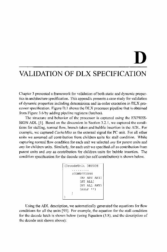
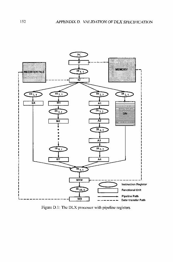
Chapter 3 presented a framework for validation of both static and dynamic proper-ties in architecture specification. This appendix presents a case study for validationof dynamic properties including determinism and in-order execution in DLX pro-cessor specification. Figure D. 1 shows the DLX processor pipeline that is obtainedfrom Figure 3.6 by adding pipeline registers (latches).
The structure and behavior of the processor is captured using the EXPRES-SION ADL [5]. Based on the discussion in Section 3.2.1, we captured the condi-tions for stalling, normal flow, branch taken and bubble insertion in the ADL. Forexample, we captured CacheMiss as the external signal for PC unit. For all otherunits we assumed all contribution from children units for stall condition. Whilecapturing normal flow condition for each unit we selected any for parent units andany for children units. Similarly, for each unit we specified all as contribution fromparent units and any as contribution for children units for bubble insertion. Thecondition specification for the decode unit (no self contribution) is shown below.
(DecodeUnit DECODE
(CONDITIONS(NF ANY ANY)(ST ALL)(BI ALL ANY)(SELF "")
Using the ADL description, we automatically generated the equations for flowconditions for all the units [95]. For example, the equation for the stall conditionfor the decode latch is shown below (using Equation (3.8), and the description ofthe decode unit shown above):
152 APPENDIX D. VALIDATION OF DLX SPECIFICATION
r-^ REGISTER FILE
Instruction Register
1 Functional Unit
WBPipeline Path
- #•• Data-transfer Path
Figure D.I: The DLX processor with pipeline registers

153
condfRxx = (STIR2A . STIRl2 . STIR23 . STIR24)XNIRlA.SQIRlA (D.I)
IR2.4 represents latch for the multicycle unit. So we assumed a signal busyinternal to IR2.4 which remained set for n cycles. The busy can be treated as STjR^as shown in Equation (3.8).
The necessary equations for verifying the properties such as determinism andin-order execution are generated from the given ADL description. We show here asmall trace of the property checking to demonstrate the simplicity and elegance ofthe underlying model. We show that the determinism property is satisfied for IR\\using the modeling above:
+ STIR2A) . XNIRlA . SQIR
= (STIRll +STIR2a +STIRl3
(5*7/̂ 2̂ . STIRl2 . 57/^2^ . STm2A) . XNIRxx . SQIRlA +XNIRlA +SQIRlA
= (XNjRlA . SQiR{A) . ((STjR2A +STjRl2 +ST/R2J +STJR2A)
(STIR2A .ST1R22.'STIR23 . STIR2A)) +XNIRxA +SQIRlA
= (XNIRlA . SQIRltl) + (XNIRlA +SQIRltl)= 1
We have used Espresso to minimize the equations. The minimized equationsare analyzed to verify whether the properties are violated or not. The completeverification took 41 seconds on a 333 MHz Sun Ultra-5 with 128M RAM. Ourframework determined that the Equation (3.33) is violated and generated a sim-ple instruction sequence which violates in-order execution: floating-point additionfollowed by integer addition. The decode unit issued floating point addition Ifaddoperation in cycle n to floating-point adder pipeline (Al - A4) and an integer addi-tion operation / / ^ to integer ALU (EX) at cycle n+1. The instruction Iiadd reachedjoin node (MEM unit) prior to I/add-
We modified the ADL description to change the stall condition depending oncurrent instruction in decode unit and the instructions active in the integer ALU,MUL, FADD, and DIV pipelines. The current instruction will not be issued (de-code stalls) if it leads to out-of-order execution. Our framework generated equa-tions for processor model and the properties. The only difference is STj^\ fordecode unit (Equation (3.8)) becomes:

154 APPENDIX D. VALIDATION OF DLX SPECIFICATION
where, the numbers 1,2, 3, and 4 correspond to the integer ALU, MUL, FADDand DIV pipelines respectively. The signal SXy is 1 if the latest instruction inpipeline x is active for less than (T(X) - x(y)) cycles. Here, i(x) returns the to-tal number of clock cycles needed by pipeline x (T(1) = 1,T(2) = 7, T(3) = 4,x(4) = 25). The instructions I\, h, h, and I4 represent the instructions supportedby the pipelines 1, 2, 3, and 4 respectively. For example, if current instruction ish (multiply) and there is a instruction in DIV unit which is active for less than 18cycles (x(4) — x(2) = 25 - 7 = 18), then the decode should stall. Otherwise, it leadsto out-of-order execution. Note that, the equation does not have any term for I4.This is because Sx^ can never be 1 since (x(x) — T (4) ) is always negative. For thesame reason, all the components in the equation does not have four SXly terms.
The Equation (3.34) is violated for this modeling for /i?9}i. The instructionsequence generated by our framework for this failure consists of a multiply opera-tion (issued by decode unit in cycle n) followed by a floating-point add operation(issued by decode unit in cycle (n + 3)). As a result both the operations reach /ifyiat cycle (n+7). We modified the ADL description to redefine SX)y signal: it is 1 ifthe latest instruction in pipeline x is active for less than or equal to (x(x) —%{y))cycles. The in-order execution was successful for this modeling. In such a simplesituation this kind of specification mistakes might appear as trivial, but when thearchitecture gets complicated and exploration iterations and varieties increase, thepotential for introducing bugs also increases.

EDESIGN SPACE EXPLORATION
An architect needs to explore the possible design alternatives and consider the ap-plication scenarios before finalizing the design decisions. Each design alternativeneeds to be prototyped and evaluated under typical user environment (using appli-cation programs or synthetic benchmarks) to gather necessary estimates includingarea, power, and performance values. It may be necessary to generate both sim-ulator and hardware (synthesizable HDL) models. The simulator produces profil-ing data and thus may answer questions concerning the instruction-set, the perfor-mance of an algorithm and the required size of memory and registers. However,the hardware prototype is necessary to estimate the required silicon area, clockfrequency, and power consumption.
Manual or semi-automatic generation of prototypes is a time consuming pro-cess. This can be done only by a set of skilled designers. Furthermore, the interac-tion among the different teams, such as specification developers, HDL designers,and simulator developers makes rapid architectural exploration infeasible. As aresult, system architects rarely have tools or the time to explore architecture alter-natives to find the best possible design. This situation is very expensive in bothtime and engineering resources, and has a substantial impact on time-to-market.Without automation and a unified development environment, the design processis prone to error and may lead to inconsistencies between hardware and softwarerepresentations.
Figure E. 1 shows our ADL-driven architectural exploration framework. Theapplication programs are compiled using the compiler1 [4] and simulated using thegenerated simulator. The feedback (performance and code size) is used to mod-ify the ADL specification of the architecture. Similarly, the generated hardware isused to obtain the area, clock frequency, power and performance estimates. The
^ h e compiler is also generated from the architecture specification.

156 APPENDIX E. DESIGN SPACE EXPLORATION
goal is to find the best possible processor, coprocessor, and memory architecturefor the given set of application programs. The techniques for generating simulatorsand hardware models are described in Chapter 4. Section E. 1 presents explorationexperiments using the generated simulator. The exploration experiments using gen-erated hardware models are described in Section E.2.
Architecture Specification( English Document)
1
CompilerGenerator
SimulatorGenerator
HardwareModel
I8
- -(Synthesis• Automatic• Manual• Feedback
Figure E. 1: Architecture exploration framework
E.I Simulator Generation and Exploration
We have performed extensive exploration experiments by varying different archi-tectural features: exploration varying MIPS R10K processor features [104], co-processor based exploration [94], and memory subsystem exploration using TI C6xarchitecture [98].

E.I. SIMULATOR GENERATION AND EXPLORATION 157
Exploration varying Processor Features
Contemporary superscalar processors use in-order completion (graduation) to en-sure sequential execution behavior in the presence of out-of-order execution. Here,we explore the MIPS R10K processor in the presence of out-of-order graduationwithout violating functional correctness. The MIPS R10000 [50] is a dynamic,superscalar microprocessor that implements the 64-bit Mips-4 instruction-set ar-chitecture. It fetches and decodes four instructions per cycle and dynamically is-sues them to five fully-pipelined, low-latency execution units. Instructions can befetched and executed speculatively beyond branches. Instructions graduate in orderupon completion.
We have described the MIPS R10K architecture using functional abstraction.The fetch unit function is invoked with the appropriate parameter values. For ex-ample, the number of instructions fetched per cycle and the number of instructionssent to decode stage per cycle are set to four. The decode functionality is instan-tiated with read connection from fetch latch and write connections to Memlssue,Intlssue and Floatlssue units. The decoded instruction is added in the completionqueue (ActiveList) which maintains the program order. The decode logic decideswhere to dispatch (Memlssue, Intlssue or Floatlssue) a particular instruction basedon the supported opcodes information available in the control table.
The Intlssue, Floatlssue and Memlssue functions are instantiated with a reser-vation station size of 16 entries. Each issue unit performs operand read and RAWhazard detection (using appropriate sub-functions) before performing out-of-orderissue. Execution units are instantiated using appropriate opcode functionalities.The Address Queue (Memlssue unit) reads data and tag using virtual address whilethe physical address is computed. It checks whether the load is a hit or miss oncethe physical address is available. This is different from conventional way of hit ormiss detection. In conventional architectures the load request is done using phys-ical address and hit or miss detection is done inside the memory subsystem. Thisillustrates our ability to reuse the hit or miss detection sub-functions in the proces-sor side (that remains conventionally in the memory side). Similarly, we captureregister files and memory hierarchy by instantiating components using appropriateparameters.
We have described the MIPS R10K architecture (with in-order graduation and8 entry Active List) and generated the software toolkit. We have modified thedescription to perform out-of-order graduation and generated the simulator. Wehave used a set of benchmarks from the multimedia and DSP domains.
Figure E.2 presents a subset of the experiments we ran to study the performanceimprovement due to out-of-order graduation. The light bar presents the number ofexecution cycles when in-order graduation is used whereas the dark bar presents

158 APPENDIX E. DESIGN SPACE EXPLORATION
the number of execution cycles when out-of-order graduation is used. We observean average performance improvement of 10%. During in-order graduation certaininstructions (independent of the instructions above in the Active List) completeexecution but are not allowed to graduate since some long latency operations areon top of the Active List and yet to complete. As a result, the Active List becomesfull soon and the decode stalls. This situation becomes more prominent whenthe top instruction is a load and the load misses. We have modified the memorysubsystem to study the impact of cache misses along with out-of-order graduationand observed up to 27% performance improvement (in benchmark StateExcerptwhen hit ratio is zero). The complete study of the out-of-order graduation for theMIPS R10K processor can be found in [104].
3000 -.
2500-
2000 -
1500 -
1000 -
500 -
1 In-order graduation
S Out-of-order graduation
Hydro StateExcerpt Linear Integrate Lowpass
Figure E.2: Cycle counts for different graduation styles
Due to the high modeling efficiency of functional abstraction, the original de-scription and toolkit generation took less than a week; the graduation style mod-ification and toolkit generation took less than a day; the experiments and analy-sis took few hours; the complete exploration experiment took approximately oneweek.
El. SIMULATOR GENERATION AND EXPLORATION 159
Co-processor based Exploration
In the context of co-processor codesign for programmable architectures we haveexplored the performance impact using a co-processor for the TI C6x environment.TI C6x [131] is an 8-way VLIW DSP processor with a novel memory subsystem(cache hierarchy, configurable SRAM, partitioned register file). TI C6x processorhas a deep pipeline, composed of 4 fetch stages (PG, PS, PR, PW), 2 decode stages(DP, DC), followed by the 8 functional units.
We have described the TI C6x architecture using functional abstraction. Thefetch functionality consists of four stages viz., program address generation, addresssend, wait, and receive. Each of the four stages is modeled using respective sub-functions with appropriate parameters. The architecture fetches one VLIW instruc-tion (eight parallel operations) per cycle. The decode function decodes the VLIWword and dispatches up to eight operations per cycle to eight execution units. Eachexecution unit performs operand read and hazard checks (using sub-functions). Atthe end of computation each execution unit writes back (using sub-functions) theresult to register file.
The functional units, LI, SI, Ml and Dl are connected to the "A" part of thepartitioned register file whereas the remaining functional units viz., L2, S2, M2, D2are connected to the "B" of the register file. Two cross paths, viz., IX and 2X, areused for transferring data from the other part of the partitioned register file. Eachregister file is instantiated using generic register file with 16 32-bit registers. Simi-larly, the memory subsystem consisting of scratch-pad SRAM and cache hierarchyis captured by instantiating components using appropriate parameters.
We have described the TI C6x architecture (where multiplication is done inthe functional unit) using functional abstraction and generated the software toolkit.We have modified the description by adding a co-processor (with DMA controllerand local memory) that supports multiplication and generated the simulator. Thisco-processor has its own local memory and uses DMA to transfer data from mainmemory. We then used a set of DSPStone fixed point benchmarks to explore andevaluate the effects of adding a coprocessor.
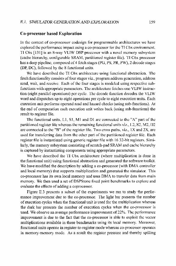
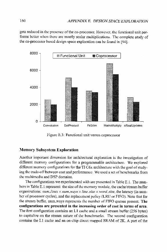
Figure E.3 presents a subset of the experiments we ran to study the perfor-mance improvement due to the co-processor. The light bar presents the numberof execution cycles when the functional unit is used for the multiplication whereasthe dark bar presents the number of execution cycles when the co-processor isused. We observe an average performance improvement of 22%. The performanceimprovement is due to the fact that the co-processor is able to exploit the vectormultiplications available in these benchmarks using its local memory. Moreover,functional units operate in register-to-register mode whereas co-processor operatesin memory-memory mode. As a result the register pressure and thereby spilling
160 APPENDIX E. DESIGN SPACE EXPLORATION
gets reduced in the presence of the co-processor. However, the functional unit per-forms better when there are mostly scalar multiplications. The complete study ofthe co-processor based design space exploration can be found in [94].
8000 -,
6000-
4000 -
2000-
! Functional Unit 1 Coprocessor
Convolution DotProduct Fir2dim MatrixMultiply nRealUpdates
Figure E.3: Functional unit versus coprocessor
Memory Subsystem Exploration
Another important dimension for architectural exploration is the investigation ofdifferent memory configurations for a programmable architecture. We exploreddifferent memory configurations for the TI C6x architecture with the goal of study-ing the trade-off between cost and performance. We used a set of benchmarks fromthe multimedia and DSP domains.
The configurations we experimented with are presented in Table E. 1. The num-bers in Table E. 1 represent: the size of the memory module, the cache/stream bufferorganizations: numJines x numjways x line size x word size, the latency (in num-ber of processor cycles), and the replacement policy (LRU or FIFO). Note that forthe stream buffer, num_ways represents the number of FIFO queues present. Theconfigurations are presented in the increasing order of cost in terms of area.The first configuration contains an LI cache and a small stream buffer (256 bytes)to capitalize on the stream nature of the benchmarks. The second configurationcontains the LI cache and an on-chip direct mapped SRAM of 2K. A part of the

E. 1. SIMULATOR GENERATION AND EXPLORATION 161
arrays in the application are mapped to the SRAM. Due to the reduced control nec-essary for the SRAM, it has a small latency (of 1 cycle), and the area requirementsare small. The third configuration contains LI and L2 caches with FIFO replace-ment policy. Due to the control necessary for the L2 cache (of size 2K), the costof this configuration is larger than the configuration 2. Configuration 4 containsan LI cache, an L2 cache of size IK and a direct mapped SRAM of size IK. Dueto the extra busses to route the data to the caches and SRAM, this configurationhas a larger cost than the previous one. The last configuration contains a largeSRAM and has the largest area requirement. All the configurations contain thesame off-chip DRAM module with a latency of 20 cycles.
Table E. 1: The Memory Subsystem Configurations
Config
1
2
3
4
5
LICache
4x2x4x4latency=l (LRU)
4x2x4x4latency=l (LRU)
4x2x4x4latency=l (FIFO)
4x2x4x4latency=l (FIFO)
L2Cache
-
16x4x8x4latency=4 (FIFO)
32x1x8x4latency=4 (FIFO)
-
SRAM
2Klatency=l
-
IKlatency=l
8Klatency=l
StreamBuffer
4x4x4x4latency=4
-
-
-
-
DRAM
latency=20
latency=20
latency=20
latency=20
latency=20
Figure E.4 presents a subset of the experiments we ran, showing the total cyclecounts (including the time spent in the processor) for the set of benchmarks fordifferent memory configurations. Even though these benchmarks are kernels, weobserved a significant variation in the trends shown by the different applications.
For instance, in tridiag and stateeq, the first configuration (even though has thelowest cost) performs better (lower cycle count means higher performance), dueto the capability of the stream buffer to exploit the stream nature of the accesspatterns. Moreover, in these applications the most expensive configuration (con-figuration 5), containing the large SRAM behaves poorly, due to the fact that notall the arrays fit in the SRAM, and the lack of LI cache to compensate the largelatency of the DRAM creates its toll on the performance.
The expected trend of higher cost - higher performance was apparent in theapplications integrate and lowpass, While the stream buffer in configuration 1 hasa comparable performance to the other configurations, the configuration 5 has the

162 APPENDIX E. DESIGN SPACE EXPLORATION
best behavior due to the low latency of the direct mapped on-chip SRAM. Thecomplete study of the memory subsystem exploration can be found in [98].
90000 -i
75000 -
60000 -
45000 -
30000 -
15000 -
BConfigi BConfig2 DConfig3 •Config4 BConfig5
Tridiag Stateeq Integrate Compress Lowpass
Figure E.4: Cycle counts for the memory configurations
E.2 Hardware Generation and Exploration
We have performed various exploration experiments using the generated hardwaremodels for DLX processor based on silicon area, power, and clock frequency [92,93]. We have used Synopsys Design Compiler [127] to synthesize the generatedHDL description using LSI 10K technology libraries and obtained area, power andclock frequency values.
Table E.2: Synthesis Results: RISC-DLX vs Public-DLX
RISC-DLXPublic-DLX
HDL Code(lines)77586529
Area(gates)208 K159 K
Speed(MHz)
3544
Power(mW)32.627.4
To ensure the functional correctness, the generated HDL model is validatedagainst the generated simulator using Livermoore loops (LL1 - LL24) and mul-
R2. HARDWARE GENERATION AND EXPLORATION 163
timedia kernels (compress, GSR, laplace, linear, lowpass, SOR and wavelet). Toensure the fidelity of the generated area, power, and performance numbers, wehave compared our generated HDL (RISC version of the DLX) with the hand-written HDL model publicly available from eda.org [44]. Table E.2 presents thecomparative results between the generated DLX model (RISC-DLX) and the handwritten DLX model (Public-DLX). Our generated design (RISC-DLX) is 20-30%off in terms of area, power and clock speed. We believe these are reasonable rangesfor early rapid system prototyping and exploration.
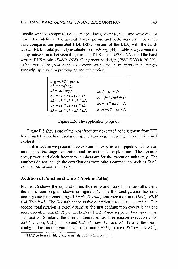
arg — th2 * piovncl = cos(arg)si = sin(arg)c2 = cl * cl - si 's2 — cl * si + clc3 = cl * c2 - si 's3 = c2*sl + s2
ksl;*sl;ks2;*cl;
int4 = in * 4;jO =jr * int4 +1;
kO =ji * int4 +1;jlast =jO + in - / ;
Figure E.5: The application program
Figure E.5 shows one of the most frequently executed code segment from FFTbenchmark that we have used as an application program during micro-architecturalexploration.
In this section we present three exploration experiments: pipeline path explo-ration, pipeline stage exploration and instruction-set exploration. The reportedarea, power, and clock frequency numbers are for the execution units only. Thenumbers do not include the contributions from others components such as Fetch,Decode, MEM and WriteBack.
Addition of Functional Units (Pipeline Paths)
Figure E.6 shows the exploration results due to addition of pipeline paths usingthe application program shown in Figure E.5. The first configuration has onlyone pipeline path consisting of Fetch, Decode, one execution unit (Exl), MEMand WriteBack. The Exl unit supports five operations: sin, cos, +, - and x. Thesecond configuration is exactly same as the first configuration except it has onemore execution unit (Ex2) parallel to Exl. The Ex2 unit supports three operations:+, - and x. Similarly, the third configuration has three parallel execution units:Exl (+, -, x), Ex2 (+, -, x) and Ex3 (sin, cos, +, - and x). Finally, the fourthconfiguration has four parallel execution units: Exl (sin, cos), Ex2 (+, -, MAC2),
2 MAC performs multiply-and-accumulate of the form ax b + c

164 APPENDIX E. DESIGN SPACE EXPLORATION
Ex3 and Ex4, where Ex3 and Ex4 are customized functional units that performax b + cxd.
75 -,
60 -
45 -
Schedule Length DArea (K gates)
30 -
15 -
1 2 3 4Pipeline Paths
Figure E.6: Pipeline path exploration
The application program requires fewer number of cycles (schedule length)due to the addition of pipeline paths whereas the area and power requirement in-creases. The fourth configuration is interesting since both area and schedule lengthdecrease due to addition of specialized hardware and removal of operations fromother execution units.
Addition of Pipeline Stages
Figure E.7 presents exploration experiments due to addition of pipeline stages inthe multiplier unit. The first configuration is a one-stage multi-cycle multiplier.The second, third and fourth configurations use multipliers with two, three andfour stages respectively. The clock frequency (speed) is improved due to additionof pipeline stages. The fourth configuration generated 30% speed improvement atthe cost of 13% area increase over the third configuration.

E.2. HARDWARE GENERATION AND EXPLORATION 165
Addition of Operations
Figure E.8 presents exploration results for addition of opcodes using three proces-sor configurations. The three configurations are shown in Figure E.8. The firstconfiguration has four parallel execution units: FU1, FU2, FU3 and FU4. TheFU1 supports three operations: +, -, and x. The FU2, FU3 and FU4 supports (+,-, x), {and, or) and (sin, cos) respectively. The second configuration is obtained byadding a cos operation in the FU3 of the first configuration. This generated reduc-tion of schedule length of the application program at the cost of increase in area.The third configuration is obtained by adding multipliers both in FU3 and FU4 ofthe second configuration. This generated best possible (using +, -, x, sin and cos)schedule length for the application program shown in Figure E.5.
Clock Frequency (MHz) • Area (K gates)
1 2 3 4Pipeline Stages
Figure E.7: Pipeline stage exploration
Each iteration in our exploration framework is in the order of hours to daysdepending on the amount of modification needed in the ADL and the synthesistime. However, each iteration will be in the order of weeks to months for manualor semi-automatic development of HDL models. The reduction of exploration timeis at least an order of magnitude.
We have also performed various micro-architectural explorations of the MIPS4000 processor. A public release of the exploration framework is available fromhttp://www.cecs.uci.edu/~express. This release also supports graphical user inter-

166 APPENDIX E. DESIGN SPACE EXPLORATION
30 n
20 -
Schedule Length H Area (K gates)
10 -
Confjg 1 Confjg 2 Confjg 3
Figure E.8: Instruction-set exploration
face (GUI). The architecture can be described (or modified) using the GUI. TheADL specification as well as the software toolkit are automatically generated fromthe graphical description to enable rapid design space exploration of programmablearchitectures.

References
[1] A. Aharon and D. Goodman and M. Levinger and Y. Lichtenstein and Y.Malka and C. Metzger and M. Molcho and G. Shurek. Test program gen-eration for functional verification of PowerPC processors in IBM. In Pro-ceedings of Design Automation Conference (DAC), pages 279-285, 1995.
[2] A. Bunker and G. Gopalakrishnan and S. Mckee. Validation, verification,and testing of computer software. ACM Computing Surveys, 9(1): 1-32, Jan-uary 2004.
[3] A. Fauth and A. Knoll. Automatic generation of DSP program developmenttools. In Proceedings oflnt'l Conf Acoustics, Speech and Signal Processing(ICASSP), pages 457-460, 1993.
[4] A. Halambi and A. Shrivastava and N. Dutt and A. Nicolau. A customizablecompiler framework for embedded systems. In Proceedings of Software andCompilers for Embedded Systems (SCOPES), 2001.
[5] A. Halambi and P. Grun and V. Ganesh and A. Khare and N. Dutt and A.Nicolau. EXPRESSION: A language for architecture exploration throughcompiler/simulator retargetability. In Proceedings of Design Automationand Test in Europe (DATE), pages 485^90, 1999.
[6] A. Inoue and H. Tomiyama and F. Eko and H. Kanbara and H. Yasuura.A programming language for processor based embedded systems. In Pro-ceedings of Asia Pacific Conference on Hardware Description Languages(APCHDL), pages 89-94, 1998.
[7] A. Inoue and H. Tomiyama and H. Okuma and H. Kanbara and H. Yasuura.Language and compiler for optimizing datapath widths of embedded sys-tems. IEICE Trans. Fundamentals, E81-A(12):2595-2604, 1998.

168 REFERENCES
[8] A. Khare and N. Savoiu and A. Halambi and P. Grun and N. Dutt and A.Nicolau. V-SAT: A visual specification and analysis tool for system-on-chip exploration. In Proceedings ofEUROMICRO Conference, pages 1196—1203, 1999.
[9] A. Nohl and G. Braun and O. Schliebusch and R. Leupers and H. Meyrand A. Hoffmann. A universal technique for fast and flexible instruction-setarchitecture simulation. In Proceedings of Design Automation Conference(DAC), pages 22-27, 2002.
[10] ARC Cores, http://www.arccores.com.
[11] Bob Bentley. High level validation of next-generation microprocessors. InProceedings of High Level Design Validation and Test (HLDVT), 2002.
[12] C. Ejik. Sequential equivalence checking without state space traversal. InProceedings of Design Automation and Test in Europe (DATE), pages 618—623, 1998.
[13] C. Jacobi. Formal verification of complex out-of-order pipelines by combin-ing model-checking and theorem-proving. In E. Brinksma and K. Larsen,editor, Proceedings of Computer Aided Verification (CAV), volume 2404 ofLNCS, pages 309-323. Springer-Verlag, 2002.
[14] C. Seger and R. Bryant. Formal verification by symbolic evaluation ofpartially-ordered trajectories. In Formal Methods in System Design, vol-ume 6, pages 147-189, March 1995.
[15] C. Siska. A processor description language supporting retargetable multi-pipeline DSP program development tools. In Proceedings of InternationalSymposium on System Synthesis (ISSS), pages 31-36, 1998.
[16] Chris Basoglu and Woobin Lee and John Setel O'Donnell. TheMAPlOOOAVLIW Mediaprocessor, 2000.
[17] CoWare LISATek Products, http://www.coware.com.
[18] D. Anastasakis and R. Damiano and H. Ma and T. Stanion. A practicaland efficient method for compare-point matching. In Proceedings of DesignAutomation Conference (DAC), pages 305-310, 2002.
[19] D. Campenhout and T. Mudge and J. Hayes. High-level test generation fordesign verification of pipelined microprocessors. In Proceedings of DesignAutomation Conference (DAC), pages 185-188, 1999.

REFERENCES 169
[20] D. Cyrluk. Microprocessor verification in PVS: A methodology and simpleexample. Technical report, SRI-CSL-93-12, 1993.
[21] D. Kastner. TDL: A hardware and assembly description languages. Techni-cal Report TDL 1.4, Saarland University, Germany, 2000.
[22] D. Lanneer and J. Praet and A. Kifli and K. Schoofs and W. Geurts and F.Thoen and G. Goossens. CHESS: Retargetable code generation for embed-ded DSP processors. In Code Generation for Embedded Processors., pages85-102. Kluwer Academic Publishers, 1995.
[23] E. Schnarr and J. Larus. Fast out-of-order processor simulation using mem-oization. In Architectural Support for Programming Languages and Oper-ating Systems (ASPLOS), pages 283-294, 1998.
[24] E. Schnarr and M. Hill and J. Larus. Facile: A language and compiler forhigh-performance processor simulators. In Programming Language Designand Implementation (PLDI), pages 321-331, 2001.
[25] E. Witchel and M. Rosenblum. Embra: Fast and flexible machine simula-tion. In Measurement and Modeling of Computer Systems, pages 68-79,1996.
[26] F. Corno and G. Cumani and M. Reorda and G. Squillero. Fully automatictest program generation for microprocessor cores. In Proceedings of DesignAutomation and Test in Europe (DATE), pages 1006-1011, 2003.
[27] F. Engel and J. Nuhrenberg and G. Fettweis. A generic tool set for ap-plication specific processor architectures. In Proceedings of InternationalSymposium on Hardware/Software Codesign (CODES), 2000.
[28] F. Lohr and A. Fauth and M. Freericks. Sigh/sim: An environment for retar-getable instruction set simulation. Technical Report 1993/43, Dept. Com-puter Science, Tech. Univ. Berlin, Germany, 1993.
[29] F. Pong and M. Dubois. Verification techniques for cache coherence proto-cols. ACM Computing Surveys, 29(1):82-126, 1997.
[30] G. Hadjiyiannis and P. Russo and S. Devadas. A methodology for accu-rate performance evaluation in architecture exploration. In Proceedings ofDesign Automation Conference (DAC), pages 927-932, 1999.
[31] G. Hadjiyiannis and S. Hanono and S. Devadas. ISDL: An instruction set de-scription language for retargetability. In Proceedings of Design AutomationConference (DAC), pages 299-302, 1997.

170 REFERENCES
[32] Gordon Moore. Cramming more components onto integrated circuits. Elec-tronics, 38(8), 1965.
[33] Gregory S Spirakis. Designing for 65nm and Beyond. Keynote Address atDesign Automation and Test in Europe (DATE), 2004.
[34] H. Akaboshi. A Study on Design Support for Computer Architecture Design.PhD thesis, Dept. of Information Systems, Kyushu University, Japan, Jan1996.
[35] H. Akaboshi and H. Yasuura. Behavior extraction of MPU from HDL de-scription. In Proceedings of Asia Pacific Conference on Hardware Descrip-tion Languages (APCHDL), 1994.
[36] H. Chockler and O. Kupferman and R. Kurshan and M. Vardi. A practicalapproach to coverage in model checking. In Proceedings of Computer AidedVerification (CAV), volume 2102 of LNCS, pages 66-78. Springer-Verlag,2001.
[37] H. Iwashita and S. Kowatari and T. Nakata and F. Hirose. Automatic testpattern generation for pipelined processors. In Proceedings of InternationalConference on Computer-Aided Design (ICCAD), pages 580-583, 1994.
[38] H. Tomiyama and A. Halambi and P. Grun and N. Dutt and A. Nicolau.Architecture description languages for systems-on-chip design. In Proceed-ings of Asia Pacific Conference on Chip Design Language, pages 109-116,1999.
[39] http://pjro.metsa.astem.or.jp/udli. UDL/ISimulation/Synthesis Environment,1997.
[40] http://www-cad.eecs.berkeley.edu/Software/software.html. Espresso.
[41 ] http://www-ee.engr.ccny.cuny.edu/notes/ee210/eqntott_man.html. Eqntott.
[42] http://www.axysdesign.com. Axys Design Automation.
[43] http://www.es.cmu.edu/~modelcheck. Symbolic Model Verifier.
[44] http://www.eda.org/rassp/vhdl/models/processor.html. Synthesizable DLX.
[45] http://www.ics.uci.edu/~express. Exploration framework using EXPRES-SION.
[46] http://www.improvsys.com. Improv Inc.

REFERENCES 111
[47] http://www.lucent.com/micro/Starcore. Starcore, Next Generation DSPs.
[48] http://www.motorola.com. MPC7450 Microprocessor.
[49] http://www.retarget.com. Target Compiler Technologies.
[50] http://www.sgi.com. MIPS Rl0000 Microprocessor.
[51] http://www.simplescalar.com. Simplescalar
[52] http://www.sparc.com/resource.htm#V8. The SPARC Architecture Manual,Version 8.
[53] J. Burch and D. Dill. Automatic verification of pipelined microprocessorcontrol. In D. Dill, editor, Proceedings of Computer Aided Verification(CAV), volume 818 of LNCS, pages 68-80. Springer-Verlag, 1994.
[54] J. Gyllenhaal and B. Rau and W. Hwu. HMDES version 2.0 specification.Technical Report IMPACT-96-3, IMPACT Research Group, Univ. of Illi-nois, Urbana. IL, 1996.
[55] J. Hennessy and D. Patterson. Computer Architecture: A Quantitative Ap-proach. Morgan Kaufmann Publishers Inc, San Mateo, CA, 1990.
[56] J. Huggins and D. Campenhout. Specification and verification of pipeliningin the arm2 rise microprocessor. ACM Transactions on Design Automationof Electronic Systems (TODAES), 3(4):563-580, October 1998.
[57] J. Levitt and K. Olukotun. Verifying correct pipeline implementation formicroprocessors. In Proceedings of International Conference on Computer-AidedDesign (ICCAD), pages 162-169, 1997.
[58] J. Marques-Silva and T. Glass. Combinational equivalence checking usingsatisfiability and recursive learning. In Proceedings of Design Automationand Test in Europe (DATE), pages 145-149, 1999.
[59] J. Miyake and G. Brown and M. Ueda and T. Nishiyama. Automatic testgeneration for functional verification of microprocessors. In Proceedings ofAsian Test Symposium (ATS), pages 292-297, 1994.
[60] J. Paakki. Attribute grammar paradigms - a high level methodology inlanguage implementation. ACM Computing Surveys, 27(2): 196-256, June1995.

172 REFERENCES
[61] J. Sato and A. Alomary and Y. Honma and T. Nakata and A. Shiomi and N.Hikichi and M. Imai. PEAS-I: A hardware/software codesign systems forASIP development. IEICE Trans. Fundamentals, E77-A(3):483-491, 1994.
[62] J. Sawada and W. D. Hunt. Processor verification with precise exceptionsand speculative execution. In A. Hu and M. Vardi, editor, Proceedings ofComputer Aided Verification (CAV), volume 1427 of LNCS, pages 135-146.Springer-Verlag, 1998.
[63] J. Shen and J. Abraham and D. Baker and T. Hurson and M. Kinkade andG. Gervasio and C. Chu and G. Hu. Functional verification of the equatorMAP 1000 microprocessor. In Proceedings of Design Automation Confer-ence (DAC), pages 169-174, 1999.
[64] J. Skakkebaek and R. Jones and D. Dill. Formal verification of out-of-order execution using incremental flushing. In A. Hu and M. Vardi, editor,Proceedings of Computer Aided Verification (CAV), volume 1427 of LNCS,pages 98-109. Springer-Verlag, 1998.
[65] J. Zhu and D. Gajski. A retargetable, ultra-fast, instruction set simulator. InProceedings of Design Automation and Test in Europe (DATE), 1999.
[66] K. Kohno and N. Matsumoto. A new verification methodology for complexpipeline behavior. In Proceedings of Design Automation Conference (DAC),pages 816-821, 2001.
[67] Kanna Shimizu. Writing, Verifying, and Exploiting Formal Specificationsfor Hardware Designs. PhD thesis, Stanford University, 2002.
[68] L. Chen and S. Ravi and A. Raghunathan and S. Dey. A scalable software-based self-test methodology for programmable processors. In Proceedingsof Design Automation Conference (DAC), pages 548-553, 2003.
[69] L. Wang and M. Abadir and N. Krishnamurthy. Automatic generation ofassertions for formal verification of PowerPC microprocessor arrays usingsymbolic trajectory evaluation. In Proceedings of Design Automation Con-ference (DAC), pages 534-537, 1998.
[70] LEON2 Processor, http://www.gaisler.com/leon.html.
[71] M. Aagaard and B. Cook and N. Day and R. Jones. A framework for mi-croprocessor correctness statements. In T. Margaria and T. Melham, ed-itor, Proceedings of Correct Hardware Design and Verification Methods(CHARME), volume 2144 of 'LNCS, pages 433-448. Springer-Verlag, 2001.

REFERENCES 173
[72] M. Freericks. The nML machine description formalism. Technical ReportTR SM-IMP/DIST/08, TU Berlin CS Dept., 1993.
[73] M. Hartoog and J. Rowson and P. Reddy and S. Desai and D. Dunlop andE. Harcourt and N. Khullar. Generation of software tools from processordescriptions for hardware/software codesign. In Proceedings of Design Au-tomation Conference (DAC), pages 303-306, 1997.
[74] M. Hohenauer and H. Scharwaechter and K. Karuri and O. Wahlen and T.Kogel and R. Leupers and G. Ascheid and H. Meyr and G. Braun and H.Someren. A methodology and tool suite for c compiler generation fromADL processor models. In Proceedings of Design Automation and Test inEurope (DATE), pages 1276-1283, 2004.
[75] M. Itoh and S. Higaki and Y. Takeuchi and A. Kitajima and M. Imai and J.Sato and A. Shiomi. PEAS-III: An ASIP design environment. In Proceed-ings of International Conference on Computer Design (ICCD), 2000.
[76] M. Itoh and Y. Takeuchi and M. Imai and A. Shiomi. Synthesizable HDLgeneration for pipelined processors from a micro-operation description. IE-ICE Trans. Fundamentals, E00-A(3), March 2000.
[77] M. Reshadi and P. Mishra and N. Dutt. Instruction set compiled simulation:A technique for fast and flexible instruction set simulation. In Proceedingsof Design Automation Conference (DAC), pages 758-763, 2003.
[78] M. Srivas and M. Bickford. Formal verification of a pipelined microproces-sor. In IEEE Software, volume 7(5), pages 52-64, 1990.
[79] M. Velev and R. Bryant. Formal verification of superscalar microprocessorswith multicycle functional units, exceptions, and branch prediction. In Pro-ceedings of Design Automation Conference (DAC), pages 112-117, 2000.
[80] The MDES User Manual, http://www.trimaran.org, 1997.
[81] MIPS Technologies, Inc. MIPS R4000 Microprocessor User's Manual,1994.
[82] N. Krishnamurthy and M. Abadir and A. Martin and J. Abraham. Designand development paradigm for industrial formal verification tools. IEEEDesign & Test of Computers, 18(4):26-35, July-August 2001.
[83] N. Medvidovic and R. Taylor. A framework for classifying and comparingarchitecture description languages. In M. Jazayeri and H. Schauer, editor,

174 REFERENCES
Proceedings of European Software Engineering Conference (ESEC), pages60-76. Springer-Verlag, 1997.
[84] O. Schliebusch and A. Chattopadhyay and M. Steinert and G. Braun and A.Nohl and R. Leupers and G. Ascheid and H. Meyr. RTL processor synthesisfor architecture exploration and implementation. In Proceedings of DesignAutomation and Test in Europe (DATE), pages 156-160, 2004.
[85] O. Schliebusch and A. Hoffmann and A. Nohl and G. Braun and H. Meyr.Architecture implementation using the machine description language LISA.In Proceedings of Asia South Pacific Design Automation Conference (ASP-DAC) /International Conference on VLSI Design, pages 239-244, 2002.
[86] O. Wahlen and M. Hohenauer and R. Leupers and H. Meyr. Instructionscheduler generation for retragetable compilation. IEEE Design & Test ofComputers, 20(l):34-41, Jan-Feb 2003.
[87] P. Ammann and P. Black and W. Majurski. Using model checking to gener-ate tests from specifications. In Proceedings of International Conference onFormal Engineering Methods (ICFEM), pages 46-54, 1998.
[88] P. Grun and A. Halambi and N. Dutt and A. Nicolau. RTGEN: An algorithmfor automatic generation of reservation tables from architectural descrip-tions. IEEE Transactions on Very Large Scale Integration (VLSI) Systems,11(4):731-737, August 2003.
[89] P. Grun and N. Dutt and A. Nicolau. Memory aware compilation through ac-curate timing extraction. In Proceedings of Design Automation Conference(DAC), pages 316-321, 2000.
[90] P. Ho and A. Isles and T. Kam. Formal verification of pipeline control usingcontrolled token nets and abstract interpretation. In Proceedings of Inter-national Conference on Computer-Aided Design (ICCAD), pages 529-536,1998.
[91] P. Ho and Y. Hoskote and T. Kam and M. Khaira and J. O'Leary and X.Zhao and Y. Chen and E. Clarke. Verification of a complete floating-pointunit using word-level model checking. In M. Srivas and A. Camilleri, edi-tor, Proceedings of Formal Methods in Computer-Aided Design (FMCAD),volume 1166 of LNCS, pages 19-33. Springer-Verlag, 1996.
[92] P. Mishra and A. Kejariwal and N. Dutt. Rapid exploration of pipelinedprocessors through automatic generation of synthesizable RTL models. InProceedings of Rapid System Prototyping (RSP), pages 226-232, 2003.

REFERENCES 175
[93] P. Mishra and A. Kejariwal and N. Dutt. Synthesis-driven exploration ofpipelined embedded processors. In Proceedings of International Conferenceon VLSI Design, 2004.
[94] P. Mishra and F. Rousseau and N. Dutt and A. Nicolau. Architecture de-scription language driven design space exploration in the presence of co-processors. In Proceedings of Synthesis and System Integration of MixedTechnologies (SASIM), 2001.
[95] P. Mishra and H. Tomiyama and N. Dutt and A. Nicolau. Architecture de-scription language driven verification of in-order execution in pipelined pro-cessors. Technical Report UCI-ICS 01-20, University of California, Irvine,2000.
[96] P. Mishra and H. Tomiyama and N. Dutt and A. Nicolau. Automatic veri-fication of in-order execution in microprocessors with fragmented pipelinesand multicycle functional units. In Proceedings of Design Automation andTest in Europe (DATE), pages 36-43, 2002.
[97] P. Mishra and J. Astrom and N. Dutt and A. Nicolau. Functional abstractionof programmable embedded systems. Technical Report UCI-ICS 01-04,University of California, Irvine, January 2001.
[98] P. Mishra and M. Mamidipaka and N. Dutt. Processor-memory co-exploration using an architecture description language. ACM Transactionson Embedded Computing Systems (TECS), 3(1): 140-162, 2004.
[99] P. Mishra and N. Dutt. Automatic modeling and validation of pipeline spec-ifications. ACM Transactions on Embedded Computing Systems (TECS),3(1):114-139, 2004.
[100] P. Mishra and N. Dutt. Graph-based functional test program generation forpipelined processors. In Proceedings of Design Automation and Test in Eu-rope (DATE), pages 182-187, 2004.
[101] P. Mishra and N. Dutt. Architecture description languages for programmableembedded systems. IEE Proceedings on Computers and Digital Techniques,2005.
[102] P. Mishra and N. Dutt and A. Nicolau. Functional abstraction driven de-sign space exploration of heterogeneous programmable architectures. InProceedings of International Symposium on System Synthesis (ISSS), pages256-261,2001.

176 REFERENCES
[103] P. Mishra and N. Dutt and A. Nicolau. Specification of hazards, stalls, inter-rupts, and exceptions in EXPRESSION. Technical Report UCI-ICS 01-05,University of California, Irvine, 2001.
[104] P. Mishra and N. Dutt and A. Nicolau. A study of out-of-order completionfor the MIPS R10K superscalar processor. Technical Report UCI-ICS 01-06, University of California, Irvine, January 2001.
[105] P. Mishra and N. Dutt and H. Tomiyama. Towards automatic validation ofdynamic behavior in pipelined processor specifications. Kluwer Design Au-tomation for Embedded Systems(DAES), 8(2-3):249-265, June-September2003.
[106] P. Mishra and N. Dutt and N. Krishnamurthy and M. Abadir. A top-downmethodology for validation of microprocessors. IEEE Design & Test ofComputers, 21(2): 122-131, 2004.
[107] P. Mishra and P. Grun and N. Dutt and A. Nicolau. Processor-memory co-exploration driven by an architectural description language. In Proceedingsof International Conference on VLSI Design, pages 70—75, 2001.
[108] P. Paulin and C. Liem and T. May and S. Sutarwala. FlexWare: A flexi-ble firmware development environment for embedded systems. In Prof ofDagstuhl Workshop on Code Generation for Embedded Processors, pages67-84, 1994.
[109] Paul C. Clements. A survey of architecture description languages. In Pro-ceedings of International Workshop on Software Specification and Design(IWSSD), pages 16-25, 1996.
[110] Prabhat Mishra. Specification-driven Validation of Programmable Embed-ded Systems. PhD thesis, University of California, Irvine, March 2004.
[ I l l ] R.Bryant. Symbolic simulation - techniques and applications. In Proceed-ings of Design Automation Conference (DAC), pages 517-521, 1990.
[112] R. Bryant and C. Seger. Formal verification of digital circuits using sym-bolic ternary system models. In Proceedings of Computer Aided Verification(CAV), pages 121-146, 1990.
[113] R. Cmelik and D. Keppel. Shade: A fast instruction-set simulator for ex-ecution profiling. ACM SIGMETRICS Performance Evaluation Review,22(1): 128-137, May 1994.
REFERENCES 111
[114] R. Ho and C. Yang and Mark A. Horowitz and D. Dill. Architecture vali-dation for processors. In Proceedings of International Symposium on Com-puter Architecture (ISCA), 1995.
[115] R. Jhala and K. L. McMillan. Microarchitecture verification by composi-tional model checking. In G. Berry et al., editor, Proceedings of ComputerAided Verification (CAV), volume 2102 of LNCS, pages 396-410. Springer-Verlag,2001.
[116] R. Leupers and P. Marwedel. Retargetable generation of code selectors fromHDL processor models. In Proceedings of European Design and Test Con-ference (EDTC), pages 140-144, 1997.
[117] R. Leupers and P. Marwedel. Retargetable code generation based on struc-tural processor descriptions. Design Automation for Embedded Systems,3(l):75-108, 1998.
[118] R. M. Hosabettu. Systematic Verification Of Pipelined Microprocessors.PhD thesis, Department of Computer Science, University of Utah, 2000.
[119] S. Fine and A. Ziv. Coverage directed test generation for functional ver-ification using bayesian networks. In Proceedings of Design AutomationConference (DAC), pages 286-291, 2003.
[120] S. Hanono and S. Devadas. Instruction selection, resource allocation, andscheduling in the AVIV retargetable code generator. In Proceedings of De-sign Automation Conference (DAC), pages 510-515, 1998.
[121] S. Pees and A. Hoffmann and H. Meyr. Retargetable compiled simulationof embedded processors using a machine description language. ACM Trans-actions on Design Automation of Electronic Systems, 5 (4): 815-834, Oct.2000.
[122] S. Thatte and J. Abraham. Test generation for microprocessors. IEEE Trans-actions on Computers, C-29(6):429-441, June 1980.
[123] S. Ur and Y. Yadin. Micro architecture coverage directed generation of testprograms. In Proceedings of Design Automation Conference (DAC), pages175-180, 1999.
[124] S. Wang and S. Malik. Synthesizing operating system based device driversin embedded systems. In Proceedings of International Symposium on Hard-ware/Software Codesign and System Synthesis (CODES+ISSS), pages 37-44, 2003.

178 REFERENCES
[125] StrongArm. StrongARMProcessors, http://developer.intel.com, 2000.
[126] SUN Microsystems. UltraSPARC Hi User's Manual, 1997.
[127] Synopsys. http://www.synopsys.com.
[128] Synopsys Formality, http://www.synopsys.com.
[129] T. Morimoto and K. Yamazaki and H. Nakamura and T. Boku and K.Nakazawa. Superscalar processor design with hardware description lan-guage aidl. In Proceedings of Asia Pacific Conference on Hardware De-scription Languages (APCHDL), 1994.
[130] Tensilica Inc. http://www.tensilica.com.
[131] Texas Instruments. TMS320C6201 CPU and Instruction Set ReferenceGuide, 1998.
[132] V. Rajesh and Rajat Moona. Processor modeling for hardware softwarecodesign. In Proceedings of International Conference on VLSI Design,pages 132-137, 1999.
[133] V. Zivojnovic and S. Pees and H. Meyr. LISA - machine description lan-guage and generic machine model for HW/SW co-design. In IEEE Work-shop on VLSI Signal Processing, pages 127-136, 1996.
[134] Verisity Design, Inc. http://www.verisity.com.
[135] Verisity Verification Vault, https://www.verificationvault.com.
[136] W. Adrion and M. Branstad and J. Cherniavsky. Validation, verification,and testing of computer software. ACM Computing Surveys, 14(2): 159—192,June 1982.
[137] W. Qin and S. Malik. Architecture Description Languages for RetargetableCompilation, in The Compiler Design Handbook: Optimizations & MachineCode Generation. CRC Press, 2002.
[138] www.intel.com. IA-64 Architecture.
[139] www.rs.e-technik.tu-darmstadt.de/TUD/res/dlxdocu/SuperscalarDLX.html.A Superscalar Version of the DLX Processor.

Index
ADL, 10, 16antecedent, 86application programs, 3architectural exploration, 155architectural flaws, 8Architecture Description Language, 16architecture manual, 15architecture validation, 83assembler, 16attribute grammar, 18
BDD, 85behavior, 16, 25behavioral ADL, 18, 130Boolean, 83branch taken, 52bubble insertion, 49
code coverage, 8compiler, 16completeness, 10, 39connectedness, 10, 34consequent, 86constrained-random, 113coprocessor, 8, 15counterexample, 98
data-transfer edge, 31data-transfer path, 24, 31debugger, 16design complexity, 3design space exploration, 16determinism, 10, 55, 151
DMA, 23DSE, 16DSP, 11dynamic behavior, 48
embedded systems, 3equivalence checking, 10, 87exception, 147execution edge, 33execution path, 103exploration, 16EXPRESSION, 17
false data-transfer path, 37false pipeline path, 35fault model, 103finiteness, 10, 41formal techniques, 83formal verification, 9, 83FSM, 8functional abstraction, 11, 69functional coverage, 7, 95, 103, 105functional errors, 4functional verification, 4
golden reference model, 7graph coverage, 98graph model, 96
hardware ADL, 16hardware description language, 21HDL, 19
implementation, 83

180 INDEX
implementation bugs, 8in-order execution, 10, 55, 151instruction register, 51instruction-set, 16instruction-set simulation, 9interface synthesis, 18interrupt, 147interrupt handler, 149ISDL, 17
LISA, 17logic bugs, 4LRU, 88
MDES, 17memory, 15memory subsystem, 8MIMOLA, 17mixed ADL, 18, 134MMU, 88model checker, 96modeling language, 20
nML, 17normal flow, 49
operation edge, 33operation execution, 103
partial ADL, 18pipeline behavior, 29pipeline edge, 31pipeline execution, 103pipeline latch, 51pipeline path, 24, 31processor, 15processor core, 8programmable architectures, 3programmable components, 3programming language, 20property checking, 83
RADL, 17reference model, 77register read/write, 103register-transfer level, 5RISC, 11RTL, 5RTL design, 83
sequential execution, 52Sim-nML, 17simulation, 83simulation vectors, 5simulator, 16SMV, 57SOC,4Software ADL, 16software toolkit, 16specification, 15specification language, 15squash, 49stall, 49state space explosion, 83static behavior, 30static verification, 87STE, 85structural ADL, 19, 127structure, 16,24,31superscalar, 11symbolic simulation, 85synthesis, 16system-on-chip, 3
ternary simulation, 85test generation, 16, 95, 106test programs, 99top-down validation, 8
Valen-C, 17validation, 16VLIW, 11