sus316 - pisco pneumatic equipmenten.pisco.co.jp/media/book_en/h1-03.pdf1. taper thread is not...
TRANSCRIPT
108
http://www.pisco.co.jp
StainlessSeries
ChemicalSeries
PPSeries
EGSeries
Anti-spatter& Brass Series
Die TemperatureControl
MinimalSeries
Stop FittingSeries
RotarySeries
Twist-ProofFitting
Block andConnector
Coupling
ColorCap
FITTING
TUBE
VALVE
CONTROLLERMAKE-TO-ORDERPRODUCTS
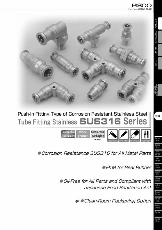
Push-In Fitting Type of Corrosion Resistant Stainless SteelTube Fitting Stainless SUS316 Series
●Corrosion Resistance SUS316 for All Metal Parts
●Oil-Free for All Parts and Compliant with Japanese Food Sanitation Act
●FKM for Seal Rubber
Chemical Industry Food IndustryMedical Industry Medicine Industry
Clean-roompackaging
Non-grease
option
●Clean-Room Packaging Option
Copper alloy free material
Fitting SeriesTube Fitting Stainless SUS316 Series
StainlessSeries
109
MiniSeries
StandardSeries
FITT
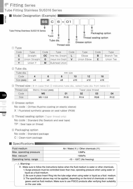
ING ■ Model Designation (Example)
CSS 6 01
② Tube dia.
③ Thread size (※ In case that ③ indicates tube dia., select tube dia. from table ②)
Tube dia. mm sizeCode 4 6 8 10 12 16
Size (mm) ø4 ø6 ø8 ø10 ø12 ø16
Thread size Metric thread (mm) Taper pipe threadCode M5 01 02 03 04Size M5×0.8 R1/8 R1/4 R3/8 R1/2
■ Specifi cationsFluid medium Air / Water(※ ) / Other chemicals (※)
Max. operating pressure 1.0MPa
Max. vacuum -100kPa
Operating temp. range -15~120℃ (No freezing)
※ . Make sure to follow the instructions below when the fluid medium is water or other chemicals. 1. Surge pressure must be controlled lower than max. operating pressure when using water or
liquid as a fluid medium. 2. Be sure to place Insert Ring into the tube edge when using water or liquid as a fluid medium. 3. The specification above may not be applied, depending on the kind of chemicals or mixed
gases used as fluid medium. Make sure to use PISCO products after verifying their suitability on the user side.
Warning
Code Type Code Type Code Type Code TypeC Straight OC Inner Hex. Straight L Elbow B Branch TeeU Union Straight G Unequal Union Straight V Union Elbow E Union TeeY Union Y M Bulkhead Union
① Type
④ Grease option No code:Oil-free (fluorine coating on elastic sleeve) X:Fluoriated synthetic grease on seal rubber (FKM)
⑤ Thread sealing option (Taper thread only) No code:Standard (No Sealock and seal tape) TP:Seal tape on thread
Tube Fitting Stainless SUS316 Series①
Type②
Tube dia.
⑤Thread sealing option
④Grease option③
Thread size
⑥Packaging option
⑥ Packaging option No code:Standard package C:Clean-room package
110
http://www.pisco.co.jp
StainlessSeries
ChemicalSeries
PPSeries
EGSeries
Anti-spatter& Brass Series
Die TemperatureControl
MinimalSeries
Stop FittingSeries
RotarySeries
Twist-ProofFitting
Block andConnector
Coupling
ColorCap
FITTING
TUBE
VALVE
CONTROLLERMAKE-TO-ORDERPRODUCTS
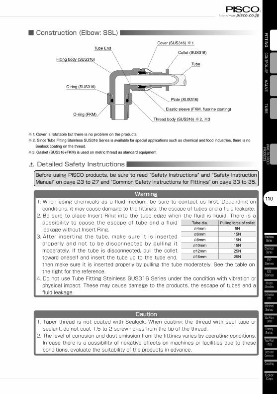
■ Construction (Elbow: SSL)
Elastic sleeve (FKM, fluorine coating)O-ring (FKM)
Tube
Collet (SUS316)
Cover (SUS316) ※1
Thread body (SUS316) ※2, ※3
Tube End
Fitting body (SUS316)
C-ring (SUS316)
Plate (SUS316)
Detailed Safety InstructionsBefore using PISCO products, be sure to read “Safety Instructions” and “Safety Instruction Manual” on page 23 to 27 and “Common Safety Instructions for Fittings” on page 33 to 35.
Warning1. When using chemicals as a fluid medium, be sure to contact us first. Depending on
conditions, it may cause damage to the fittings, the escape of tubes and a fluid leakage.2. Be sure to place Insert Ring into the tube edge when the fluid is liquid. There is a
possibility to cause the escape of tube and a fluid leakage without Insert Ring.
3. After inserting the tube, make sure it is inserted properly and not to be disconnected by pulling it moderately. If the tube is disconnected, pull the collet toward oneself and insert the tube up to the tube end, then make sure it is inserted properly by pulling the tube moderately. See the table on the right for the reference.
4. Do not use Tube Fitting Stainless SUS316 Series under the condition with vibration or physical impact. These may cause damage to the products, the escape of tubes and a fluid leakage.
Caution1. Taper thread is not coated with Sealock. When coating the thread with seal tape or
sealant, do not coat 1.5 to 2 screw ridges from the tip of the thread.2. The level of corrosion and dust emission from the fittings varies by operating conditions.
In case there is a possibility of negative effects on machines or facilities due to these conditions, evaluate the suitability of the products in advance.
Tube dia. Pulling force of colletø4mm 5Nø6mm 15Nø8mm 15Nø10mm 15Nø12mm 25Nø16mm 25N
※1. Cover is rotatable but there is no problem on the products.
※2. Since Tube Fitting Stainless SUS316 Series is available for special applications such as chemical and food industries, there is no
Sealock coating on the thread.
※3. Gasket (SUS316+FKM) is used on metric thread as standard equipment.
Fitting SeriesTube Fitting Stainless SUS316 Series
StainlessSeries
111
MiniSeries
StandardSeries
FITTING
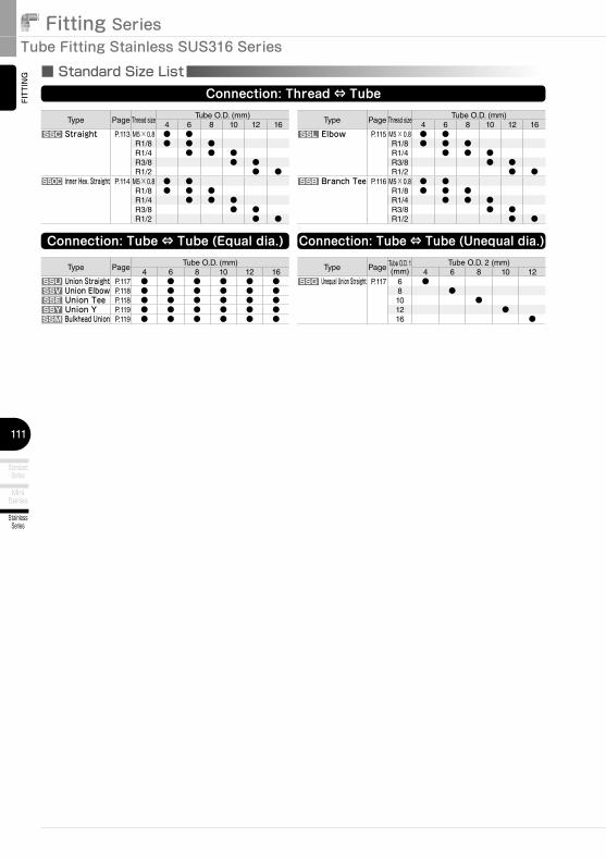
Type Page Thread sizeTube O.D. (mm)
4 6 8 10 12 16SSC Straight P.113 M5×0.8 ● ●
R1/8 ● ● ●R1/4 ● ● ●R3/8 ● ●R1/2 ● ●
SSOC Inner Hex. Straight P.114 M5×0.8 ● ●R1/8 ● ● ●R1/4 ● ● ●R3/8 ● ●R1/2 ● ●
■ Standard Size ListConnection: Thread ⇔ Tube
Connection: Tube ⇔ Tube (Equal dia.)
Type PageTube O.D. (mm)
4 6 8 10 12 16SSU Union Straight P.117 ● ● ● ● ● ●SSV Union Elbow P.118 ● ● ● ● ● ●SSE Union Tee P.118 ● ● ● ● ● ●SSY Union Y P.119 ● ● ● ● ● ●SSM Bulkhead Union P.119 ● ● ● ● ● ●
Type Page Tube O.D. 1(mm)
Tube O.D. 2 (mm)4 6 8 10 12
SSG Unequal Union Straight P.117 6 ●8 ●10 ●12 ●16 ●
Connection: Tube ⇔ Tube (Unequal dia.)
Type Page Thread sizeTube O.D. (mm)
4 6 8 10 12 16SSL Elbow P.115 M5×0.8 ● ●
R1/8 ● ● ●R1/4 ● ● ●R3/8 ● ●R1/2 ● ●
SSB Branch Tee P.116 M5×0.8 ● ●R1/8 ● ● ●R1/4 ● ● ●R3/8 ● ●R1/2 ● ●
112
http://www.pisco.co.jp
StainlessSeries
ChemicalSeries
PPSeries
EGSeries
Anti-spatter& Brass Series
Die TemperatureControl
MinimalSeries
Stop FittingSeries
RotarySeries
Twist-ProofFitting
Block andConnector
Coupling
ColorCap
FITTING
TUBE
VALVE
CONTROLLERMAKE-TO-ORDERPRODUCTS
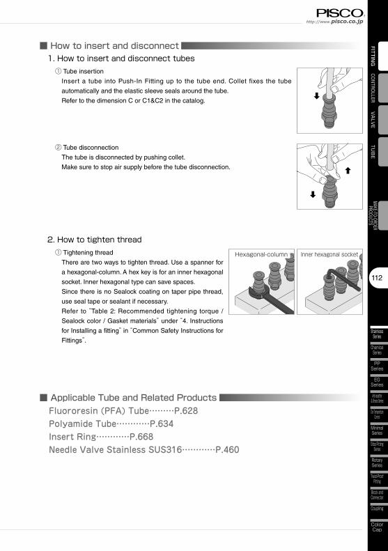
■ How to insert and disconnect 1. How to insert and disconnect tubes
① Tube insertion
Insert a tube into Push-In Fitting up to the tube end. Collet fixes the tube
automatically and the elastic sleeve seals around the tube.
Refer to the dimension C or C1&C2 in the catalog.
② Tube disconnection
The tube is disconnected by pushing collet.
Make sure to stop air supply before the tube disconnection.
2. How to tighten thread① Tightening thread
There are two ways to tighten thread. Use a spanner for
a hexagonal-column. A hex key is for an inner hexagonal
socket. Inner hexagonal type can save spaces.
Since there is no Sealock coating on taper pipe thread,
use seal tape or sealant if necessary.
Refer to “Table 2: Recommended tightening torque /
Sealock color / Gasket materials” under “4. Instructions
for Installing a fitting” in “Common Safety Instructions for
Fittings”.
Hexagonal-column Inner hexagonal socket
■ Applicable Tube and Related ProductsFluororesin (PFA) Tube………P.628Polyamide Tube…………P.634Insert Ring…………P.668Needle Valve Stainless SUS316…………P.460

Fitting SeriesTube Fitting Stainless SUS316 Series
StainlessSeries
113
MiniSeries
StandardSeries
FITT
ING
CAD data is available at PISCO website.CADCAD3D 3D CAD data is available at PISCO website.
SSCøP
H
RB B
L LC C
A A
øDøPøD
H
R
Taper threadMetric thread type
Straight
Unit:mm
Model codeTube O.D.
øDR A B L C
Hex.H
øPEffective area(mm2)
Weight(g)
CADfile name
SSC4-M5④⑥4
M5×0.8 3 24.2 21.218.2 10 9.8
3 6 SSC4-M5
SSC4-01④⑤⑥ R1/8 8 27.2 23.3 5 8.7 SSC4-01
SSC6-M5④⑥6
M5×0.8 3 25.6 22.619.6
1211.8
3 8.4 SSC6-M5
SSC6-01④⑤⑥ R1/8 8 27.6 23.7 13.5 9.9 SSC6-01
SSC6-02④⑤⑥ R1/4 11 31.6 25.6 14 13.8 18 SSC6-02
SSC8-01④⑤⑥8
R1/8 8 30.7 26.821.7 14 13.8
20.5 12 SSC8-01
SSC8-02④⑤⑥ R1/4 11 33.7 27.7 26.8 18 SSC8-02
SSC10-02④⑤⑥10
R1/4 11 36 3025.5 17 16.8
27.5 22 SSC10-02
SSC10-03④⑤⑥ R3/8 12 38 31.6 28.5 29 SSC10-03
SSC12-03④⑤⑥12
R3/8 12 39.8 33.527.3
2119.8
45.5 37 SSC12-03
SSC12-04④⑤⑥ R1/2 15 42.8 34.6 22 51.8 55 SSC12-04
SSC16-04④⑤⑥ 16 R1/2 15 49.7 41.6 32.7 24 23.7 79.8 59 SSC16-04
※1. “L” is a reference value for height dimension after tightening taper thread.
※2. ④ in Model code / Replaced with “X” for Fluorinated synthetic grease
※3. ⑤ in Model code / Replaced with “TP” for Seal tape
※4. ⑥ in Model code / Replaced with “C” for Clean-room package
compliant
CADCAD3D
114
http://www.pisco.co.jp
StainlessSeries
ChemicalSeries
PPSeries
EGSeries
Anti-spatter& Brass Series
Die TemperatureControl
MinimalSeries
Stop FittingSeries
RotarySeries
Twist-ProofFitting
Block andConnector
Coupling
ColorCap
FITTING
TUB
EVA
LVECONTROLLER
MAKE-TO-ORDERPRODUCTS
CAD data is available at PISCO website.CADCAD3D 3D CAD data is available at PISCO website.
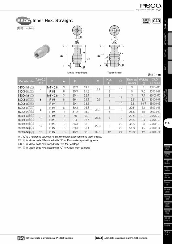
SSOC
øP
øD
øP
øD
H H
C C
A A
L L
B B
RR
Taper threadMetric thread type
Inner Hex. Straight
Unit:mm
Model codeTube O.D.
øDR A B L C
Hex.H
øPEffective area(mm2)
Weight(g)
CADfile name
SSOC4-M5④⑥4
M5×0.8 3 22.7 19.718.2
210
3 5 SSOC4-M5
SSOC4-01④⑤⑥ R1/8 8 25.7 21.8 3 5 7.6 SSOC4-01
SSOC6-M5④⑥6
M5×0.8 3 25.1 22.119.6
212
3 7.7 SSOC6-M5
SSOC6-01④⑤⑥ R1/8 8 26.1 22.24
13.5 8.4 SSOC6-01
SSOC6-02④⑤⑥ R1/4 11 29.1 23.1 14 13.8 14.7 SSOC6-02
SSOC8-01④⑤⑥8
R1/8 8 30.2 26.321.7
514
20.5 12 SSOC8-01
SSOC8-02④⑤⑥ R1/4 11 31.2 25.2 6 26.8 15 SSOC8-02
SSOC10-02④⑤⑥10
R1/4 11 36 3025.5 6 17
27.5 21 SSOC10-02
SSOC10-03④⑤⑥ R3/8 12 34 27.6 28.5 24 SSOC10-03
SSOC12-03④⑤⑥12
R3/8 12 36.3 3027.3 8
20 45.5 28 SSOC12-03
SSOC12-04④⑤⑥ R1/2 15 39.3 31.1 22 51.8 45 SSOC12-04
SSOC16-04④⑤⑥ 16 R1/2 15 46.7 38.6 32.7 12 24 79.8 47 SSOC16-04
※1. “L” is a reference value for height dimension after tightening taper thread.
※2. ④ in Model code / Replaced with “X” for Fluorinated synthetic grease
※3. ⑤ in Model code / Replaced with “TP” for Seal tape
※4. ⑥ in Model code / Replaced with “C” for Clean-room package
compliant
CADCAD3D

Fitting SeriesTube Fitting Stainless SUS316 Series
StainlessSeries
115
MiniSeries
StandardSeries
FITT
ING
CAD data is available at PISCO website.CADCAD3D 3D CAD data is available at PISCO website.
SSL
E
H
R
C
øD
øP
AL
B
EC
H
RAL
B
øD øP
Taper threadMetric thread type
Elbow
Unit:mm
Model codeTube O.D.
øDR A B L C
Hex.H
øP EEffective area(mm2)
Weight(g)
CADfile name
SSL4-M5④⑥4
M5×0.8 3 17 18.918.2 10 9.8 22.2
3 12 SSL4-M5
SSL4-01④⑤⑥ R1/8 8 19 19.9 3.8 15 SSL4-01
SSL6-M5④⑥6
M5×0.8 3 19 21.919.6
1211.8 23.6
3 19 SSL6-M5
SSL6-01④⑤⑥ R1/8 8 20.5 22.4 11.8 20 SSL6-01
SSL6-02④⑤⑥ R1/4 11 23 22.9 14 10 27 SSL6-02
SSL8-01④⑤⑥8
R1/8 8 2325.9 21.7 14 13.8 26.2
21 26 SSL8-01
SSL8-02④⑤⑥ R1/4 11 25 20.5 31 SSL8-02
SSL10-02④⑤⑥10
R1/4 11 28.5 30.925.5 17 16.8 30.5 28
45 SSL10-02
SSL10-03④⑤⑥ R3/8 12 28.5 30.6 51 SSL10-03
SSL12-03④⑤⑥12
R3/8 12 30 33.627.3
2119.8 33.3
52 69 SSL12-03
SSL12-04④⑤⑥ R1/2 15 34 35.7 22 49.5 89 SSL12-04
SSL16-04④⑤⑥ 16 R1/2 15 36 39.7 32.7 24 23.7 40.7 68.8 105 SSL16-04
※1. “L” is a reference value for height dimension after tightening taper thread.
※2. ④ in Model code / Replaced with “X” for Fluorinated synthetic grease
※3. ⑤ in Model code / Replaced with “TP” for Seal tape
※4. ⑥ in Model code / Replaced with “C” for Clean-room package
compliant
CADCAD3D
116
http://www.pisco.co.jp
StainlessSeries
ChemicalSeries
PPSeries
EGSeries
Anti-spatter& Brass Series
Die TemperatureControl
MinimalSeries
Stop FittingSeries
RotarySeries
Twist-ProofFitting
Block andConnector
Coupling
ColorCap
FITTING
TUB
EVA
LVECONTROLLER
MAKE-TO-ORDERPRODUCTS
CAD data is available at PISCO website.CADCAD3D 3D CAD data is available at PISCO website.
2-E2-C
H
R
2-ø
D2-ø
PA
LB
2-E2-C
2-ø
D
2-ø
PA
LB H
R
Taper threadMetric thread type
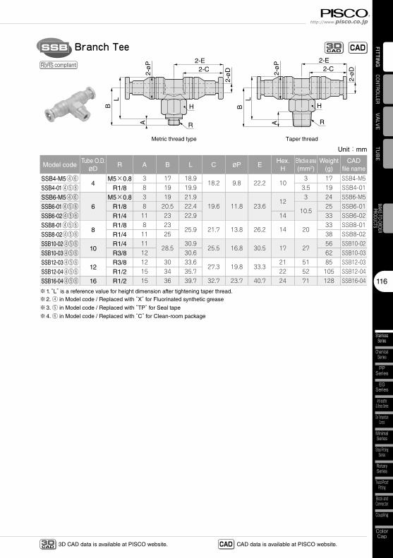
Branch TeeSSB
Unit:mm
Model codeTube O.D.
øDR A B L C øP E
Hex.H
Effective area(mm2)
Weight(g)
CADfile name
SSB4-M5④⑥4
M5×0.8 3 17 18.918.2 9.8 22.2 10
3 17 SSB4-M5
SSB4-01④⑤⑥ R1/8 8 19 19.9 3.5 19 SSB4-01
SSB6-M5④⑥6
M5×0.8 3 19 21.919.6 11.8 23.6
123 24 SSB6-M5
SSB6-01④⑤⑥ R1/8 8 20.5 22.410.5
25 SSB6-01
SSB6-02④⑤⑥ R1/4 11 23 22.9 14 33 SSB6-02
SSB8-01④⑤⑥8
R1/8 8 2325.9 21.7 13.8 26.2 14 20
33 SSB8-01
SSB8-02④⑤⑥ R1/4 11 25 38 SSB8-02
SSB10-02④⑤⑥10
R1/4 1128.5
30.925.5 16.8 30.5 17 27
56 SSB10-02
SSB10-03④⑤⑥ R3/8 12 30.6 62 SSB10-03
SSB12-03④⑤⑥12
R3/8 12 30 33.627.3 19.8 33.3
21 51 85 SSB12-03
SSB12-04④⑤⑥ R1/2 15 34 35.7 22 52 105 SSB12-04
SSB16-04④⑤⑥ 16 R1/2 15 36 39.7 32.7 23.7 40.7 24 71 128 SSB16-04
※1. “L” is a reference value for height dimension after tightening taper thread.※2. ④ in Model code / Replaced with “X” for Fluorinated synthetic grease
※3. ⑤ in Model code / Replaced with “TP” for Seal tape
※4. ⑥ in Model code / Replaced with “C” for Clean-room package
compliant
CADCAD3D
Fitting SeriesTube Fitting Stainless SUS316 Series
StainlessSeries
117
MiniSeries
StandardSeries
FITT
ING
CAD data is available at PISCO website.CADCAD3D 3D CAD data is available at PISCO website.
BC2 C1
øD
2ø
P2
øD
1ø
P1
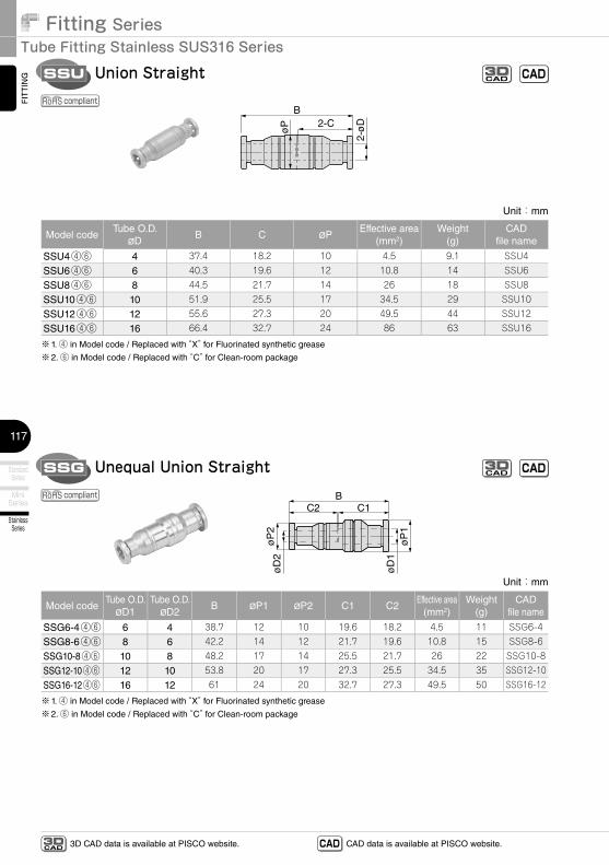
Unequal Union StraightSSG
B2-C
2-ø
D
øP
Union StraightSSU
Unit:mm
Model codeTube O.D.
øDB C øP
Effective area(mm2)
Weight(g)
CADfile name
SSU4④⑥ 4 37.4 18.2 10 4.5 9.1 SSU4
SSU6④⑥ 6 40.3 19.6 12 10.8 14 SSU6
SSU8④⑥ 8 44.5 21.7 14 26 18 SSU8
SSU10④⑥ 10 51.9 25.5 17 34.5 29 SSU10
SSU12④⑥ 12 55.6 27.3 20 49.5 44 SSU12
SSU16④⑥ 16 66.4 32.7 24 86 63 SSU16
※1. ④ in Model code / Replaced with “X” for Fluorinated synthetic grease
※2. ⑥ in Model code / Replaced with “C” for Clean-room package
Unit:mm
Model codeTube O.D.
øD1Tube O.D.
øD2B øP1 øP2 C1 C2
Effective area(mm2)
Weight(g)
CADfile name
SSG6-4④⑥ 6 4 38.7 12 10 19.6 18.2 4.5 11 SSG6-4
SSG8-6④⑥ 8 6 42.2 14 12 21.7 19.6 10.8 15 SSG8-6
SSG10-8④⑥ 10 8 48.2 17 14 25.5 21.7 26 22 SSG10-8
SSG12-10④⑥ 12 10 53.8 20 17 27.3 25.5 34.5 35 SSG12-10
SSG16-12④⑥ 16 12 61 24 20 32.7 27.3 49.5 50 SSG16-12
※1. ④ in Model code / Replaced with “X” for Fluorinated synthetic grease
※2. ⑥ in Model code / Replaced with “C” for Clean-room package
compliant
compliant
CADCAD3D
CADCAD3D
118
http://www.pisco.co.jp
StainlessSeries
ChemicalSeries
PPSeries
EGSeries
Anti-spatter& Brass Series
Die TemperatureControl
MinimalSeries
Stop FittingSeries
RotarySeries
Twist-ProofFitting
Block andConnector
Coupling
ColorCap
FITTING
TUB
EVA
LVECONTROLLER
MAKE-TO-ORDERPRODUCTS
CAD data is available at PISCO website.CADCAD3D 3D CAD data is available at PISCO website.
2-E2-C
ød
2-F
2-ø
D
2-øP
T
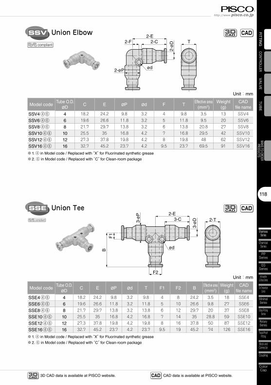
Union ElbowSSV
Unit:mm
Model codeTube O.D.
øDC E øP ød F T
Effective area(mm2)
Weight(g)
CADfile name
SSV4④⑥ 4 18.2 24.2 9.8 3.2 4 9.8 3.5 13 SSV4
SSV6④⑥ 6 19.6 26.6 11.8 3.2 5 11.8 9.5 20 SSV6
SSV8④⑥ 8 21.7 29.7 13.8 3.2 6 13.8 20.8 27 SSV8
SSV10④⑥ 10 25.5 35 16.8 4.2 7 16.8 29.5 42 SSV10
SSV12④⑥ 12 27.3 37.8 19.8 4.2 8 19.8 48 62 SSV12
SSV16④⑥ 16 32.7 45.2 23.7 4.2 9.5 23.7 69.5 91 SSV16
※1. ④ in Model code / Replaced with “X” for Fluorinated synthetic grease
※2. ⑥ in Model code / Replaced with “C” for Clean-room package
2-E3-C
F2
ød
3-ø
D
B
F1
3-ø
P
2-T
Union TeeSSE
Unit:mm
Model codeTube O.D.
øDC E øP ød T F1 F2 B
Effective area(mm2)
Weight(g)
CADfile name
SSE4④⑥ 4 18.2 24.2 9.8 3.2 9.8 4 8 24.2 3.5 18 SSE4
SSE6④⑥ 6 19.6 26.6 11.8 3.2 11.8 5 10 26.6 9.8 27 SSE6
SSE8④⑥ 8 21.7 29.7 13.8 3.2 13.8 6 12 29.7 20 37 SSE8
SSE10④⑥ 10 25.5 35 16.8 4.2 16.8 7 14 35 28.8 59 SSE10
SSE12④⑥ 12 27.3 37.8 19.8 4.2 19.8 8 16 37.8 50 87 SSE12
SSE16④⑥ 16 32.7 45.2 23.7 4.2 23.7 9.5 19 45.2 74 126 SSE16
※1. ④ in Model code / Replaced with “X” for Fluorinated synthetic grease
※2. ⑥ in Model code / Replaced with “C” for Clean-room package
compliant
compliant
CADCAD3D
CADCAD3D
Fitting SeriesTube Fitting Stainless SUS316 Series
StainlessSeries
119
MiniSeries
StandardSeries
FITT
ING
CAD data is available at PISCO website.CADCAD3D 3D CAD data is available at PISCO website.
BFT
3-C ød
J
3-ø
D
3-ø
P
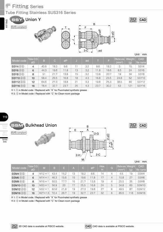
Union YSSY
BA
2-GE
2-C2-H
2-ø
D2-
øP
M
Bulkhead UnionSSM
Unit:mm
Model codeTube O.D.
øDB C øP J ød T F
Effective area(mm2)
Weight(g)
CADfile name
SSY4④⑥ 4 40.8 18.2 9.8 11 3.2 9.8 18.2 3 15 SSY4
SSY6④⑥ 6 44.3 19.6 11.8 13 3.2 11.8 18.6 8.5 24 SSY6
SSY8④⑥ 8 51 21.7 13.8 15 3.2 13.8 20.7 19 34 SSY8
SSY10④⑥ 10 58.4 25.5 16.8 18 4.3 16.8 23.5 24.8 52 SSY10
SSY12④⑥ 12 64.6 27.3 19.8 21 4.3 19.8 25.3 38.5 80 SSY12
SSY16④⑥ 16 78.4 32.7 23.7 25 4.3 23.7 30.2 53 121 SSY16
※1. ④ in Model code / Replaced with “X” for Fluorinated synthetic grease
※2. ⑥ in Model code / Replaced with “C” for Clean-room package
Unit:mm
Model codeTube O.D.
øDM B E A C øP
Hex.H
GEffective area(mm2)
Weight(g)
CADfile name
SSM4④⑥ 4 M12×1 43.4 15.2 13 18.2 9.8 14 4 4.5 19 SSM4
SSM6④⑥ 6 M14×1 46.3 15.6 15 19.6 11.8 17 4 10.8 27 SSM6
SSM8④⑥ 8 M16×1 50.5 17.7 15 21.7 13.8 19 4 25.5 35 SSM8
SSM10④⑥ 10 M20×1 56.9 20 17 25.5 16.8 24 5 34.8 60 SSM10
SSM12④⑥ 12 M22×1 62.6 21.8 19 27.3 19.8 27 6 48.5 87 SSM12
SSM16④⑥ 16 M27×1.5 72.4 26.7 19 32.7 23.7 32 6 85.5 118 SSM16
※1. ④ in Model code / Replaced with “X” for Fluorinated synthetic grease
※2. ⑥ in Model code / Replaced with “C” for Clean-room package
compliant
compliant
CADCAD3D
CADCAD3D
23
Safety Instructions
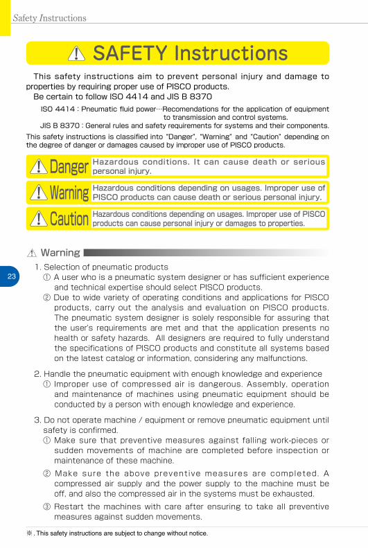
SAFETY Instructions
Warning
This safety instructions aim to prevent personal injury and damage to properties by requiring proper use of PISCO products. Be certain to follow ISO 4414 and JIS B 8370
ISO 4414:Pneumatic fluid power…Recomendations for the application of equipment to transmission and control systems.
JIS B 8370:General rules and safety requirements for systems and their components.This safety instructions is classified into “Danger”, “Warning” and “Caution” depending on the degree of danger or damages caused by improper use of PISCO products.
1. Selection of pneumatic products① A user who is a pneumatic system designer or has sufficient experience
and technical expertise should select PISCO products.② Due to wide variety of operating conditions and applications for PISCO
products, carry out the analysis and evaluation on PISCO products. The pneumatic system designer is solely responsible for assuring that the user's requirements are met and that the application presents no health or safety hazards. All designers are required to fully understand the specifications of PISCO products and constitute all systems based on the latest catalog or information, considering any malfunctions.
2. Handle the pneumatic equipment with enough knowledge and experience① Improper use of compressed air is dangerous. Assembly, operation
and maintenance of machines using pneumatic equipment should be conducted by a person with enough knowledge and experience.
3. Do not operate machine / equipment or remove pneumatic equipment until safety is confirmed.① Make sure that preventive measures against falling work-pieces or
sudden movements of machine are completed before inspection or maintenance of these machine.
② Make sure the above preventive measures are completed. A compressed air supply and the power supply to the machine must be off, and also the compressed air in the systems must be exhausted.
③ Restart the machines with care after ensuring to take all preventive measures against sudden movements.
Danger Hazardous conditions. It can cause death or serious personal injury.
Warning Hazardous conditions depending on usages. Improper use of PISCO products can cause death or serious personal injury.
Caution Hazardous conditions depending on usages. Improper use of PISCO products can cause personal injury or damages to properties.
※ . This safety instructions are subject to change without notice.
http://www.pisco.co.jphttp://www.pisco.co.jp
24
Disclaimer1. PISCO does not take any responsibility for any incidental or indirect
loss, such as production line stop, interruption of business, loss of benefits, personal injury, etc., caused by any failure on use or application of PISCO products.
2. PISCO does not take any responsibility for any loss caused by natural disasters, fires not related to PISCO products, acts by third parties, and intentional or accidental damages of PISCO products due to incorrect usage.
3. PISCO does not take any responsibility for any loss caused by improper usage of PISCO products such as exceeding the specification limit or not following the usage the published instructions and catalog allow.
4. PISCO does not take any responsibility for any loss caused by remodeling of PISCO products, or by combinational use with non-PISCO products and other software systems.
5. The damages caused by the defect of Pisco products shall be covered but limited to the full amount of the PISCO products paid by the customer.
25
Safety Instructions
SAFETY INSTRUCTION MANUAL
Danger1. Do not use PISCO products for the following applications.
① Equipment used for maintaining / handling human life and body.② Equipment used for moving / transporting human.③ Equipment specifically used for safety purposes.
Warning1. Do not use PISCO products under the following conditions.
① Beyond the specifications or conditions stated in the catalog, or the instructions.② Under the direct sunlight or outdoors.③ Excessive vibrations and impacts.④ Exposure / adhere to corrosive gas, inflammable gas, chemicals, seawater, water and vapor. *
* Some products can be used under the condition above(④), refer to the details of specification and condition of each product.
2. Do not disassemble or modify PISCO products, which affect the performance, function, and basic structure of the product.
3. Turn off the power supply, stop the air supply to PISCO products, and make sure there is no residual air pressure in the pipes before maintenance and inspection.
4. Do not touch the release-ring of push-in fitting when there is a working pressure. The lock may be released by the physical contact, and tube may fly out or slip out.
5. Frequent switchover of compressed air may generate heat, and there is a risk of causing burn injury.
6. Avoid any load on PISCO products, such as a tensile strength, twisting and bending. Otherwise, there is a risk of causing damage to the products.
7. As for applications where threads or tubes swing / rotate, use Rotary Joints, High Rotary Joints or Multi-Circuit Rotary Block only. The other PISCO products can be damaged in these applications.
8. Use only Die Temperature Control Fitting Series, Tube Fitting Stainless SUS316 Series, Tube Fitting Stainless SUS316 Compression Fitting Series or Tube Fitting Brass Series under the condition of over 60℃ (140°F) water or thermal oil. Other PISCO products can be damaged by heat and hydrolysis under the condition above.
9. As for the condition required to dissipate static electricity or provide an antistatic performance, use EG series fitting and antistatic products only, and do not use other PISCO products. There is a risk that static electricity can cause system defects or failures.
10. Use only Fittings with a characteristic of spatter-proof such as Anti-spatter or Brass series in a place where flame and weld spatter is produced. There is a risk of causing fire by sparks.
11. Turn off the power supply to PISCO products, and make sure there is no residual air pressure in the pipes and equipment before maintenance. Follow the instructions below in order to ensure safety.① Make sure the safety of all systems related to PISCO products before maintenance.② Restart of operation after maintenance shall be proceeded with care after
ensuring safety of the system by preventive measures against unexpected movements of machines and devices where pneumatic equipment is used.
③ Keep enough space for maintenance when designing a circuit.12. Take safety measures such as providing a protection cover if there is a
risk of causing damages or fires on machine / facilities by a fluid leakage.
PISCO products are designed and manufactured for use in general industrial machines. Be sure to read and follow the instructions below.
http://www.pisco.co.jphttp://www.pisco.co.jp
26
Caution1. Remove dusts or drain before piping. They may get into the peripheral
machine / facilities and cause malfunction.2. When inserting an ultra-soft tube into push-in fitting, make sure to place
an Insert Ring into the tube edge. There is a risk of causing the escape of tube and a fluid leakage without using an Insert Ring.
3. The product incorporating NBR as seal rubber material has a risk of malfunction caused by ozone crack. Ozone exists in high concentrations in static elimination air, clean-room, and near the high-voltage motors, etc. As a countermeasure, material change from NBR to HNBR or FKM is necessary. Consult with PISCO for more information.
4. Special option “Oil-free” products may cause a very small amount of a fluid leakage. When a fluid medium is liquid or the products are required to be used in harsh environments, contact us for further information.
5. In case of using non-PISCO brand tubes, make sure the tolerance of the outer tube diameter is within the limits of Table 1.
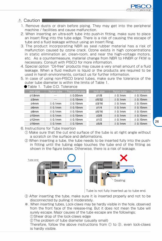
●Table 1. Tube O.D. Tolerancemm size Nylon tube Polyurethane tube inch size Nylon tube Polyurethane tubeø1.8mm ─ ±0.05mm ø1/8 ±0.1mm ±0.15mmø3mm ─ ±0.15mm ø5/32 ±0.1mm ±0.15mmø4mm ±0.1mm ±0.15mm ø3/16 ±0.1mm ±0.15mmø6mm ±0.1mm ±0.15mm ø1/4 ±0.1mm ±0.15mmø8mm ±0.1mm ±0.15mm ø5/16 ±0.1mm ±0.15mmø10mm ±0.1mm ±0.15mm ø3/8 ±0.1mm ±0.15mmø12mm ±0.1mm ±0.15mm ø1/2 ±0.1mm ±0.15mmø16mm ±0.1mm ±0.15mm ø5/8 ±0.1mm ±0.15mm
6. Instructions for Tube Insertion① Make sure that the cut end surface of the tube is at right angle without
a scratch on the surface and deformations.② When inserting a tube, the tube needs to be inserted fully into the push-
in fitting until the tubing edge touches the tube end of the fitting as shown in the figure below. Otherwise, there is a risk of leakage.
Tube end
Sealing
Tube is not fully inserted up to tube end.
③ After inserting the tube, make sure it is inserted properly and not to be disconnected by pulling it moderately.
※. When inserting tubes, Lock-claws may be hardly visible in the hole, observed from the front face of the release-ring. But it does not mean the tube will surely escape. Major causes of the tube escape are the followings; ①Shear drop of the lock-claws edge②The problem of tube diameter (usually small)Therefore, follow the above instructions from ① to ③, even lock-claws is hardly visible.
27
7. Instructions for Tube Disconnection① Make sure there is no air pressure inside of the tube, before disconnecting it.② Push the release-ring of the push-in fitting evenly and deeply enough to
pull out the tube toward oneself. By insufficient pushing of the release-ring, the tube may not be pulled out or damaged by scratch, and tube shavings may remain inside of the fitting, which may cause the leakage later.
8. Instructions for Installing a fitting① When installing a fitting, use proper tools to tighten a hexagonal-column
or an inner hexagonal socket. When inserting a hex key into the inner hexagonal socket of the fitting, be careful so that the tool does not touch lock-claws. The deformation of lock-claws may result in a poor performance of systems or an escape of the tube.
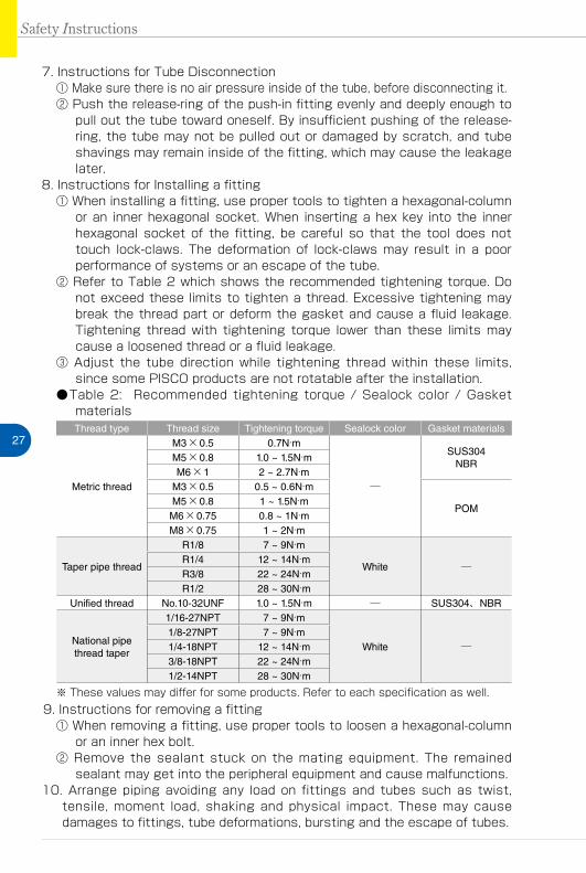
② Refer to Table 2 which shows the recommended tightening torque. Do not exceed these limits to tighten a thread. Excessive tightening may break the thread part or deform the gasket and cause a fluid leakage. Tightening thread with tightening torque lower than these limits may cause a loosened thread or a fluid leakage.
③ Adjust the tube direction while tightening thread within these limits, since some PISCO products are not rotatable after the installation.
●Table 2: Recommended tightening torque / Sealock color / Gasket materialsThread type Thread size Tightening torque Sealock color Gasket materials
Metric thread
M3×0.5 0.7N·m
─
SUS304NBR
M5×0.8 1.0 ~ 1.5N·mM6×1 2 ~ 2.7N·m
M3×0.5 0.5 ~ 0.6N·m
POMM5×0.8 1 ~ 1.5N·mM6×0.75 0.8 ~ 1N·mM8×0.75 1 ~ 2N·m
Taper pipe thread
R1/8 7 ~ 9N·m
White ─R1/4 12 ~ 14N·mR3/8 22 ~ 24N·mR1/2 28 ~ 30N·m
Unified thread No.10-32UNF 1.0 ~ 1.5N·m ─ SUS304、NBR
National pipe thread taper
1/16-27NPT 7 ~ 9N·m
White ─1/8-27NPT 7 ~ 9N·m1/4-18NPT 12 ~ 14N·m3/8-18NPT 22 ~ 24N·m1/2-14NPT 28 ~ 30N·m
※ These values may differ for some products. Refer to each specification as well.9. Instructions for removing a fitting
① When removing a fitting, use proper tools to loosen a hexagonal-column or an inner hex bolt.
② Remove the sealant stuck on the mating equipment. The remained sealant may get into the peripheral equipment and cause malfunctions.
10. Arrange piping avoiding any load on fittings and tubes such as twist, tensile, moment load, shaking and physical impact. These may cause damages to fittings, tube deformations, bursting and the escape of tubes.
Safety Instructions
Fitting SeriesFITTING
33
Common Safety Instructions for Fittings
Warning
Before selecting or using PISCO products, read the following instructions. Read the detailed instructions for individual series as well as the instructions below.
1.��Do�not�use� fittings�with� fluid�medium�other� than�air� or�water.� (Water� can�be�used�with�some�series.)�Contact�us�for�using�other�kind�of�fluid�medium�except�air�and�water.
2.��Do�not�use�fittings�except�Anti-spatter,�Brass�and�Brass�Compression�Fitting�series�in�a�place�where�the�flame�and�weld�spatter�is�produced.�There�is�a�risk�of�causing�fire�by�sparks.
3.��As�for�applications�where�threads�or�tubes�swing�/�rotate,�use�Rotary�Joints,�High�Rotary�Joints�or�Multi-Circuit�Rotary�Block�only.�The�other�PISCO�products�can�be�damaged�in�these�applications.
4.��Use� only�Die�Temperature�Control� Fitting�Series,� Tube� Fitting�Stainless�SUS316�Series,� Tube� Fitting�Stainless�SUS316�Compression� Fitting�Series�or�Tube�Fitting�Brass�Series�under� the�condition�of�over�60℃ (140° F)�water�or� thermal� oil.�Other�PISCO�products�can�be�damaged�by�heat�and�hydrolysis�under�the�condition�above.
5.��As� for� the� condition� required� to� dissipate� static� electricity� or� provide� an�antistatic�performance,�use�EG�Series�fitting�and�antistatic�products�only,�and�do� not� use� other�PISCO�products.� There� is� a� risk� that� static� electricity� can�cause�system�defects�or�failures.
6.��Avoid� any� load� on�PISCO�products,� such� as� a� tensile� strength,� twisting� and�bending.�Otherwise,�there�is�a�risk�of�causing�damage�to�the�products.
FITTING
TUBE
VALVE
CONTROLLER
StandardSeries
MiniSeries
StainlessSeries
ChemicalSeries
PPSeries
EGSeries
Anti-spatter& Brass Series
Die TemperatureControl
MinimalSeries
Stop FittingSeries
RotarySeries
Twist-ProofFitting
Block andConnector
Coupling
ColorCap
http://www.pisco.co.jphttp://www.pisco.co.jp
34
MAKE-TO-ORDERPRODUCTS
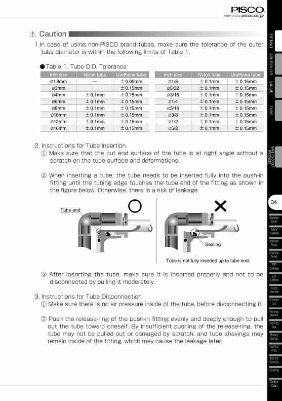
Caution1.In�case�of�using�non-PISCO�brand�tubes,�make�sure�the�tolerance�of�the�outer�tube�diameter�is�within�the�following�limits�of�Table�1.
●Table�1.�Tube�O.D.�Tolerancemm size Nylon tube Urethane tube inch size Nylon tube Urethane tubeø1.8mm ─ ±0.05mm ø1/8 ±0.1mm ±0.15mmø3mm ─ ±0.15mm ø5/32 ±0.1mm ±0.15mmø4mm ±0.1mm ±0.15mm ø3/16 ±0.1mm ±0.15mmø6mm ±0.1mm ±0.15mm ø1/4 ±0.1mm ±0.15mmø8mm ±0.1mm ±0.15mm ø5/16 ±0.1mm ±0.15mmø10mm ±0.1mm ±0.15mm ø3/8 ±0.1mm ±0.15mmø12mm ±0.1mm ±0.15mm ø1/2 ±0.1mm ±0.15mmø16mm ±0.1mm ±0.15mm ø5/8 ±0.1mm ±0.15mm
2.�Instructions�for�Tube�Insertion①�Make�sure�that�the�cut�end�surface�of�the�tube� is�at� right�angle�without�a�scratch�on�the�tube�surface�and�deformations.
②�When� inserting�a�tube,� the�tube�needs�to�be� inserted� fully� into�the�push-in�fitting�until�the�tubing�edge�touches�the�tube�end�of�the�fitting�as�shown�in�the�figure�below.�Otherwise,�there�is�a�risk�of�leakage.
Tube end
Sealing
Tube is not fully inserted up to tube end.
③�After� inserting� the� tube,�make� sure� it� is� inserted� properly� and� not� to� be�disconnected�by�pulling�it�moderately.
3.�Instructions�for�Tube�Disconnection①�Make�sure�there�is�no�air�pressure�inside�of�the�tube,�before�disconnecting�it.
②�Push�the�release-ring�of�the�push-in�fitting�evenly�and�deeply�enough�to�pull�out�the�tube�toward�oneself.�By� insufficient�pushing�of�the�release-ring,�the�tube�may�not�be�pulled�out�or�damaged�by�scratch,�and�tube�shavings�may�remain�inside�of�the�fitting,�which�may�cause�the�leakage�later.

Fitting SeriesFITTING
35
5.Instructions�for�removng�a�fitting①�When�removing�a� fitting,�use�proper�tools�to� loosen�a�hexagonal-column�or�an�inner�hexagonal�socket.
②�Remove�the�sealant�stuck�on�the�mating�equipment.�The�remained�sealant�may�get�into�the�peripheral�equipment�and�cause�malfunctions.
6.Arrange�piping�avoiding�any�load�on�fittings�and�tubes�such�as�twist,�tensile,�moment�load,�shaking�and�physical�impact.�These�may�cause�damages�to�fittings,�tube�deformations,�bursting�and�the�escape�of�tubes.
4.�Instructions�for�Installing�a�fitting①�When�installing�a�fitting,�use�proper�tools�to�tighten�a�hexagonal-column�or�an�inner�hexagonal�socket.�When�inserting�a�hex�key�into�the�inner�hexagonal�socket�of�the�fitting,�be�careful�so�that�the�tool�does�not�touch� lock-claws.�The�deformation�of� lock-claws�may�result� in�a�poor�performance�of�systems�or�an�escape�of�the�tube.
②�Refer�to�Table�2�which�shows�the� recommended�tightening�torque.�Do�not�exceed� these� limits� to� tighten� a� thread.� Excessive� tightening�may� break�the�thread�part�or�deform�the�gasket�and�cause�a�fluid� leakage.�Tightening�thread�with�tightening�torque�lower�than�these�limits�may�cause�a�loosened�thread�or�a�fluid�leakage.
③�Adjust� the� tube�direction�while� tightening� thread�within� these� limits,� since�some�PISCO�products�are�not�rotatable�the�installation.
●Table�2:�Recommended�tightening�torque�/�Sealock�color�/�Gasket�materialsThread type Thread size Tightening torque Sealock color Gasket materials
Metric thread
M3×0.5 0.7N·m
─
SUS304NBR
M5×0.8 1.0 ~ 1.5N·mM6×1 2 ~ 2.7N·m
M3×0.5 0.5 ~0.6N·m
POMM5×0.8 1 ~1.5N·mM6×0.75 0.8 ~ 1N·mM8×0.75 1 ~ 2N·m
Taper pipe thread
R1/8 7 ~ 9N·m
White ─R1/4 12 ~ 14N·mR3/8 22 ~ 24N·mR1/2 28 ~ 30N·m
Unified thread No.10-32UNF 1.0 ~ 1.5N·m ─ SUS304、NBR
National pipe thread taper
1/16-28NPT 7 ~ 9N·m
White ─1/8-27NPT 7 ~ 9N·m1/4-18NPT 12 ~ 14N·m3/8-18NPT 22 ~ 24N·m1/2-14NPT 28 ~ 30N·m
※.These�values�may�differ�for�some�products.�Refer�to�each�specification�as�well