suspension system service - denton isd
TRANSCRIPT
CH
AP
TE
R
7
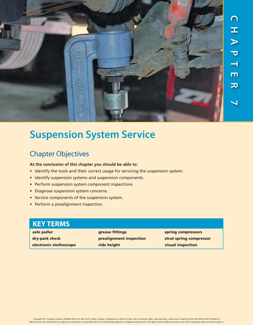
Suspension System Service
Chapter ObjectivesAt the conclusion of this chapter you should be able to:
Identify the tools and their correct usage for servicing the suspension system.
Identify suspension systems and suspension components.
Perform suspension system component inspections.
Diagnose suspension system concerns.
Service components of the suspension system.
Perform a prealignment inspection.
KEY TERMSaxle puller
dry-park check
electronic stethoscope
grease fittings
prealignment inspection
ride height
spring compressors
strut spring compressor
visual inspection
© C
enga
ge L
earn
ing
2014
Copyright 201 Cengage Learning. All Rights Reserved. May not be copied, scanned, or duplicated, in whole or in part. Due to electronic rights, some third party content may be suppressed from the eBook and/or eChapter(s).
Editorial review has deemed that any suppressed content does not materially affect the overall learning experience. Cengage Learning reserves the right to remove additional content at any time if subsequent rights restrictions require it.
202 Chapter 7 • Suspension System Service
Repairs on the suspension system are some of the most common types of repairs technicians per-
form. Because of the operating conditions and the abuse of everyday driving, suspension components such as springs and shocks, ball joints, and sway bar links often require frequent service.
Many technicians begin their careers servicing sus-pension systems before advancing into other aspects of vehicle service and repair. This is because suspension repairs utilize basic hands-on skills and help develop the critical thinking necessary for all technicians.
Tools and SafetyEvery service and repair made to a vehicle must begin and end with safety in mind. A technician who does not perform his or her work safely is not an asset; he or she is a danger. Safe working practices include proper tool use and care, following the proper repair procedures, staying focused on the tasks at hand, and taking the time to perform your work properly.
Several special tools are used to service the suspen-sion system, and using them properly will allow you to work safely and efficiently.
ToolSWithout the correct tools, many of the common repairs made to the automobile would not be possible. When you are servicing the suspension system, common hand tools as well as some specialty tools, described below, are used.
Tools for Suspension Service. Figure 7-1 through Figure 7-7 show and explain the uses of many of the tools you will use when you are working on the suspen-sion system.
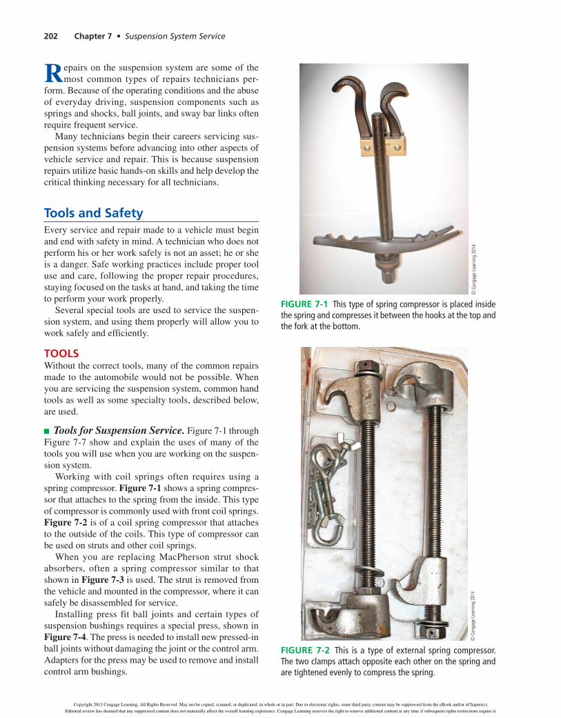
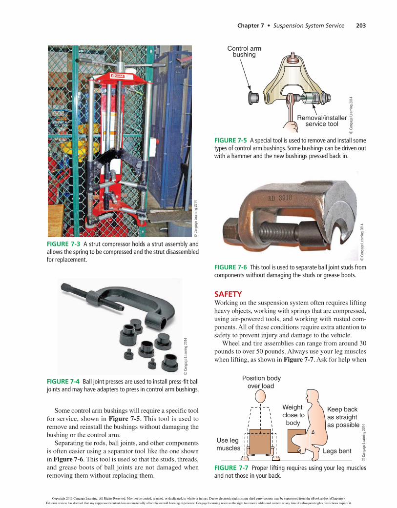
Working with coil springs often requires using a spring compressor. Figure 7-1 shows a spring compres-sor that attaches to the spring from the inside. This type of compressor is commonly used with front coil springs. Figure 7-2 is of a coil spring compressor that attaches to the outside of the coils. This type of compressor can be used on struts and other coil springs.
When you are replacing MacPherson strut shock absorbers, often a spring compressor similar to that shown in Figure 7-3 is used. The strut is removed from the vehicle and mounted in the compressor, where it can safely be disassembled for service.
Installing press fit ball joints and certain types of suspension bushings requires a special press, shown in Figure 7-4. The press is needed to install new pressed-in ball joints without damaging the joint or the control arm. Adapters for the press may be used to remove and install control arm bushings.
© C
enga
ge L
earn
ing
2014
Figure 7-1 This type of spring compressor is placed inside the spring and compresses it between the hooks at the top and the fork at the bottom.
© C
enga
ge L
earn
ing
2014
Figure 7-2 This is a type of external spring compressor. The two clamps attach opposite each other on the spring and are tightened evenly to compress the spring.
39634_ch07_rev02.indd 202 31/01/13 11:01 AM
Copyright 2013 Cengage Learning. All Rights Reserved. May not be copied, scanned, or duplicated, in whole or in part. Due to electronic rights, some third party content may be suppressed from the eBook and/or eChapter(s).
Editorial review has deemed that any suppressed content does not materially affect the overall learning experience. Cengage Learning reserves the right to remove additional content at any time if subsequent rights restrictions require it.
Chapter 7 Suspension System Service 203
Some control arm bushings will require a specific tool for service, shown in Figure 7-5. This tool is used to remove and reinstall the bushings without damaging the bushing or the control arm.
Separating tie rods, ball joints, and other components is often easier using a separator tool like the one shown in Figure 7-6. This tool is used so that the studs, threads, and grease boots of ball joints are not damaged when removing them without replacing them.
SAFETYWorking on the suspension system often requires lifting heavy objects, working with springs that are compressed, using air-powered tools, and working with rusted com-ponents. All of these conditions require extra attention to safety to prevent injury and damage to the vehicle.
Wheel and tire assemblies can range from around 30 pounds to over 50 pounds. Always use your leg muscles when lifting, as shown in Figure 7-7. Ask for help when
© C
enga
ge L
earn
ing
2014
FIGURE 7-3 A strut compressor holds a strut assembly and allows the spring to be compressed and the strut disassembled for replacement.
© C
enga
ge L
earn
ing
2014
FIGURE 7-4 Ball joint presses are used to install press-fit ball joints and may have adapters to press in control arm bushings.
Control armbushing
Removal/installerservice tool
© C
enga
ge L
earn
ing
2014
FIGURE 7-5 A special tool is used to remove and install some types of control arm bushings. Some bushings can be driven out with a hammer and the new bushings pressed back in.
© C
enga
ge L
earn
ing
2014
FIGURE 7-6 This tool is used to separate ball joint studs from components without damaging the studs or grease boots.
Position bodyover load
Keep back as straight as possible
Use leg muscles Legs bent
Weightclose to body
© C
enga
ge L
earn
ing
2014
FIGURE 7-7 Proper lifting requires using your leg muscles and not those in your back.
Copyright 201 Cengage Learning. All Rights Reserved. May not be copied, scanned, or duplicated, in whole or in part. Due to electronic rights, some third party content may be suppressed from the eBook and/or eChapter(s).
Editorial review has deemed that any suppressed content does not materially affect the overall learning experience. Cengage Learning reserves the right to remove additional content at any time if subsequent rights restrictions require it.
204 Chapter 7 • Suspension System Service
it is needed to lift a wheel and tire. Back injuries are common among service technicians and can cause long-term pain and disability.
When you are working with suspension springs, always follow the proper service procedures for safely compressing and handling the springs. Check spring compressors for wear, damage, and proper opera-tion before use. Coil springs can, if released suddenly, bounce around and cause serious injury and damage to vehicles.
Replacing suspension components often requires fighting with rusted components and fasteners. Try to clean as much rust from the area as possible with a wire brush before attempting service. This is especially important when you are using air tools, such as air impacts, because rust tends to break off and fly through the air. Apply a penetrant to rusted nuts and bolts before attempting to remove them.
Safe Work Practices. When you are performing work on the suspension system, you will often be work-ing with springs and other components that require special handling procedures. The following are some general safe work practices for working on the suspen-sion system.
• Makesurethatthevehicleisproperlyraisedandsupported before beginning any work.
• Usethepropertoolforthejobandensurethatthetool is undamaged and in proper working condition before use.
• Use the appropriate spring compressors when servicing springs and struts. Suspension springs can contain a lot of stored energy that, if released accidentally, can cause serious injury to people and damage to the vehicle.
• Beforeusingastrutspringcompressor,makesureyou are fully trained in its use and understand how to safely operate the equipment.
• Shockabsorberscontainoil,andsomepressurizethe oil with nitrogen gas. Heat should never be applied to a shock absorber body since the heat will cause pressure to build in the shock, which could cause it to rupture, sending hot oil and metal flying.
• Gas-chargedshocksshouldberelievedofthegaspressure before disposal. This often is done by drilling a small hole in the shock body and allowing the nitrogen to escape. Refer to the manufacturer’s service procedures before depressurizing a shock or throwing it away.
• Donotusesteelhammers,punches,orchiselsonother steel components.
inspection and ServiceInspection of the suspension system includes looking at the tires and the steering system. This is because prob-lems with the suspension system may show up as tire-wear issues and because there is some sharing of parts between the steering and suspension systems.
BASiC inSpeCTion proCedureSIn every aspect of automotive service and repair, you first should verify the customer’s complaint. Once you have done that, your next step is determining the cause of a concern. The best way to begin your diagnosis is to perform a thorough inspection. Before any repairs are made to the suspension system, a complete inspection of the system must be performed. One of the best ways to locate possible concerns is by performing a visual inspection.
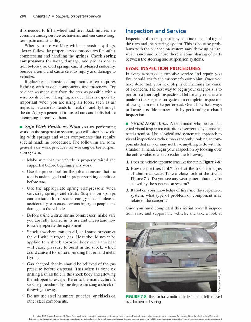
Visual Inspection. A technician who performs a good visual inspection can often discover many items that needattention.Usealogicalandsystematicapproachtovisual inspections rather than randomly looking at com-ponents that may or may not have anything to do with the situation at hand. Begin your inspection by looking over the entire vehicle, and consider the following:
1. DoesthevehicleappeartoleanlikethecarinFigure 7-8?
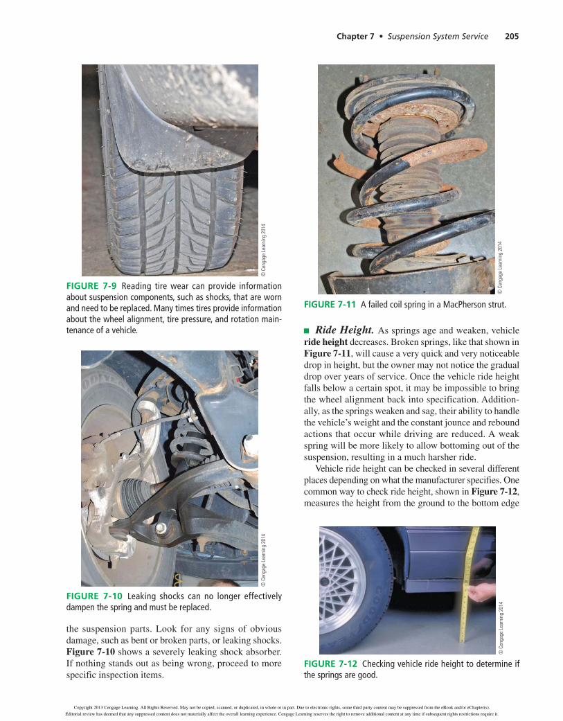
2. How do the tires look? Look at the tread for signs of abnormal wear. Take a close look at the tire in Figure 7-9.Doyouseeanywearpatternthatmaybecaused by the suspension system?
3. Based on your knowledge of tires and the suspension system, what type of problem or component may relate to the concern?
Once you have completed this initial overall inspec-tion, raise and support the vehicle, and take a look at
© C
enga
ge L
earn
ing
2014
Figure 7-8 This car has a noticeable lean to the left, caused by a broken coil spring.
39634_ch07_rev02.indd 204 31/01/13 11:02 AM
Copyright 2013 Cengage Learning. All Rights Reserved. May not be copied, scanned, or duplicated, in whole or in part. Due to electronic rights, some third party content may be suppressed from the eBook and/or eChapter(s).
Editorial review has deemed that any suppressed content does not materially affect the overall learning experience. Cengage Learning reserves the right to remove additional content at any time if subsequent rights restrictions require it.
Chapter 7 Suspension System Service 205
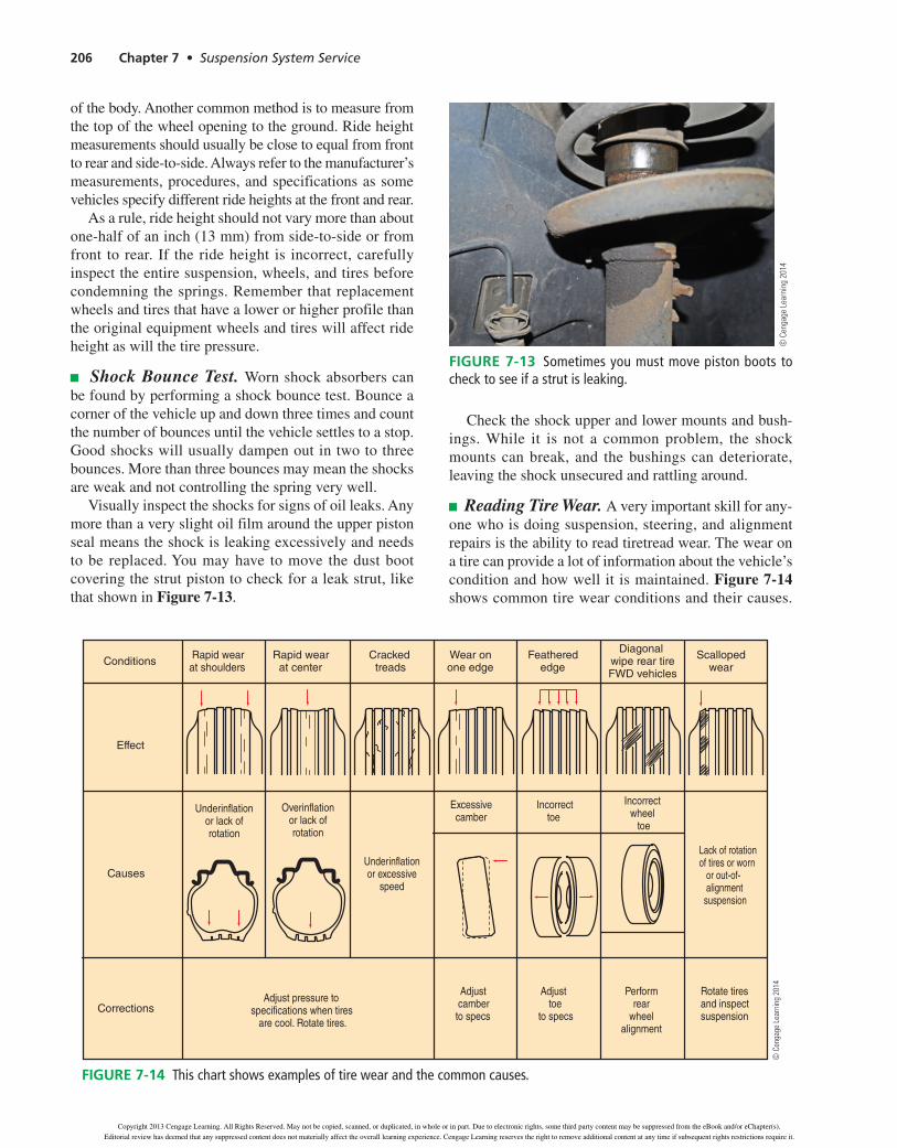
the suspension parts. Look for any signs of obvious damage, such as bent or broken parts, or leaking shocks. Figure 7-10 shows a severely leaking shock absorber. If nothing stands out as being wrong, proceed to more specific inspection items.
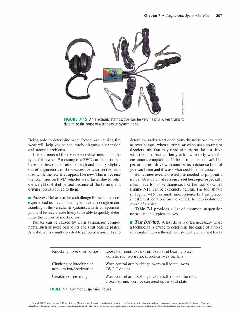
Ride Height. As springs age and weaken, vehicle ride height decreases. Broken springs, like that shown in Figure 7-11, will cause a very quick and very noticeable drop in height, but the owner may not notice the gradual drop over years of service. Once the vehicle ride height falls below a certain spot, it may be impossible to bring the wheel alignment back into specification. Addition-ally, as the springs weaken and sag, their ability to handle the vehicle’s weight and the constant jounce and rebound actions that occur while driving are reduced. A weak spring will be more likely to allow bottoming out of the suspension, resulting in a much harsher ride.
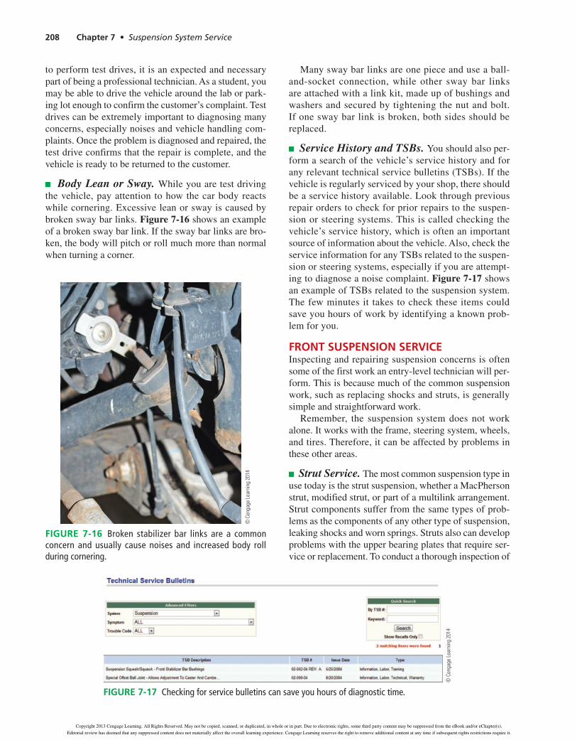
Vehicle ride height can be checked in several different places depending on what the manufacturer specifies. One common way to check ride height, shown in Figure 7-12,measures the height from the ground to the bottom edge
© C
enga
ge L
earn
ing
2014
FIGURE 7-9 Reading tire wear can provide information about suspension components, such as shocks, that are worn and need to be replaced. Many times tires provide information about the wheel alignment, tire pressure, and rotation main-tenance of a vehicle.
© C
enga
ge L
earn
ing
2014
FIGURE 7-10 Leaking shocks can no longer effectively dampen the spring and must be replaced.
© C
enga
ge L
earn
ing
2014
FIGURE 7-11 A failed coil spring in a MacPherson strut.
© C
enga
ge L
earn
ing
2014
FIGURE 7-12 Checking vehicle ride height to determine if the springs are good.
Copyright 201 Cengage Learning. All Rights Reserved. May not be copied, scanned, or duplicated, in whole or in part. Due to electronic rights, some third party content may be suppressed from the eBook and/or eChapter(s).
Editorial review has deemed that any suppressed content does not materially affect the overall learning experience. Cengage Learning reserves the right to remove additional content at any time if subsequent rights restrictions require it.
206 Chapter 7 • Suspension System Service
of the body. Another common method is to measure from the top of the wheel opening to the ground. Ride height measurements should usually be close to equal from front to rear and side-to-side. Always refer to the manufacturer’s measurements, procedures, and specifications as some vehicles specify different ride heights at the front and rear.
As a rule, ride height should not vary more than about one-half of an inch (13 mm) from side-to-side or from front to rear. If the ride height is incorrect, carefully inspect the entire suspension, wheels, and tires before condemning the springs. Remember that replacement wheels and tires that have a lower or higher profile than the original equipment wheels and tires will affect ride height as will the tire pressure.
Shock Bounce Test. Worn shock absorbers can be found by performing a shock bounce test. Bounce a corner of the vehicle up and down three times and count the number of bounces until the vehicle settles to a stop. Goodshockswillusuallydampenoutintwotothreebounces. More than three bounces may mean the shocks are weak and not controlling the spring very well.
Visually inspect the shocks for signs of oil leaks. Any more than a very slight oil film around the upper piston seal means the shock is leaking excessively and needs to be replaced. You may have to move the dust boot covering the strut piston to check for a leak strut, like that shown in Figure 7-13.
Check the shock upper and lower mounts and bush-ings. While it is not a common problem, the shock mounts can break, and the bushings can deteriorate, leaving the shock unsecured and rattling around.
Reading Tire Wear. A very important skill for any-one who is doing suspension, steering, and alignment repairs is the ability to read tiretread wear. The wear on a tire can provide a lot of information about the vehicle’s condition and how well it is maintained. Figure 7-14 shows common tire wear conditions and their causes.
© C
enga
ge L
earn
ing
2014
Figure 7-13 Sometimes you must move piston boots to check to see if a strut is leaking.
Conditions
Effect
Causes
Corrections
Rapid wearat shoulders
Rapid wear at center
Cracked treads
Wear onone edge
Feathered edge
Diagonal wipe rear tireFWD vehicles
Scalloped wear
Underinflationor lack ofrotation
Overinflationor lack ofrotation
Underinflationor excessive
speed
Excessive camber
Incorrect toe
Incorrectwheel toe
Lack of rotation of tires or worn or out-of- alignment suspension
Adjust pressure tospecifications when tires are cool. Rotate tires.
Adjust camberto specs
Adjust toeto specs
Performrear
wheelalignment
Rotate tiresand inspectsuspension
© C
enga
ge L
earn
ing
2014
Figure 7-14 This chart shows examples of tire wear and the common causes.
39634_ch07_rev02.indd 206 31/01/13 11:02 AM
Copyright 2013 Cengage Learning. All Rights Reserved. May not be copied, scanned, or duplicated, in whole or in part. Due to electronic rights, some third party content may be suppressed from the eBook and/or eChapter(s).
Editorial review has deemed that any suppressed content does not materially affect the overall learning experience. Cengage Learning reserves the right to remove additional content at any time if subsequent rights restrictions require it.
Chapter 7 • Suspension System Service 207
Being able to determine what factors are causing tire wear will help you to accurately diagnose suspension and steering problems.
It is not unusual for a vehicle to show more than one typeoftirewear.Forexample,aFWDcarthatdoesnothave the tires rotated often enough and is only slightly out of alignment can show excessive wear on the front tires while the rear tires appear like new. This is because thefronttiresonFWDvehicleswearfasterduetovehi-cle weight distribution and because of the turning and driving forces applied to them.
Noises. Noises can be a challenge for even the most experienced technician, but if you have a thorough under-standing of the vehicle, its systems, and its components, you will be much more likely to be able to quickly deter-mine the causes of most noises.
Noises can be caused by worn suspension compo-nents, such as loose ball joints and strut bearing plates. A test drive is usually needed to pinpoint a noise. Try to
determine under what conditions the noise occurs, such as over bumps, when turning, or when accelerating or decelerating. You may need to perform the test drive with the customer so that you know exactly what the customer’s complaint is. If the customer is not available, perform a test drive with another technician so both of you can listen and discuss what could be the cause.
Sometimes even more help is needed to pinpoint a noise.Use of an electronic stethoscope, especially ones made for noise diagnosis like the tool shown in Figure 7-15, can be extremely helpful. The tool shown in Figure 7-15 has small microphones that are placed in different locations on the vehicle to help isolate the cause of a noise.
Table 7-1 provides a list of common suspension noises and the typical causes.
Test Driving. A test drive is often necessary when a technician is trying to determine the cause of a noise or vibration. Even though as a student you are not likely
TABle 7-1 Common suspension noises
Knocking noise over bumps Loose ball joint, worn strut, worn strut bearing plate, worn tie rod, worn shock, broken sway bar link
Clunking or knocking on acceleration/deceleration
Worn control arm bushings, worn ball joints, worn FWDCVjoint
Creaking or groaning Worn control arm bushings, worn ball joints or tie rods, broken spring, worn or damaged upper strut plate
© C
enga
ge L
earn
ing
2014
Figure 7-15 An electronic stethoscope can be very helpful when trying to determine the cause of a suspension system noise.
39634_ch07_rev02.indd 207 31/01/13 11:02 AM
Copyright 2013 Cengage Learning. All Rights Reserved. May not be copied, scanned, or duplicated, in whole or in part. Due to electronic rights, some third party content may be suppressed from the eBook and/or eChapter(s).
Editorial review has deemed that any suppressed content does not materially affect the overall learning experience. Cengage Learning reserves the right to remove additional content at any time if subsequent rights restrictions require it.
208 Chapter 7 • Suspension System Service
to perform test drives, it is an expected and necessary part of being a professional technician. As a student, you may be able to drive the vehicle around the lab or park-ing lot enough to confirm the customer’s complaint. Test drives can be extremely important to diagnosing many concerns, especially noises and vehicle handling com-plaints. Once the problem is diagnosed and repaired, the test drive confirms that the repair is complete, and the vehicle is ready to be returned to the customer.
Body Lean or Sway. While you are test driving the vehicle, pay attention to how the car body reacts while cornering. Excessive lean or sway is caused by broken sway bar links. Figure 7-16 shows an example of a broken sway bar link. If the sway bar links are bro-ken, the body will pitch or roll much more than normal when turning a corner.
Many sway bar links are one piece and use a ball-and-socket connection, while other sway bar links are attached with a link kit, made up of bushings and washers and secured by tightening the nut and bolt. If one sway bar link is broken, both sides should be replaced.
Service History and TSBs. You should also per-form a search of the vehicle’s service history and for any relevant technical service bulletins (TSBs). If the vehicle is regularly serviced by your shop, there should be a service history available. Look through previous repair orders to check for prior repairs to the suspen-sion or steering systems. This is called checking the vehicle’s service history, which is often an important source of information about the vehicle. Also, check the service information for any TSBs related to the suspen-sion or steering systems, especially if you are attempt-ing to diagnose a noise complaint. Figure 7-17 shows an example of TSBs related to the suspension system. The few minutes it takes to check these items could save you hours of work by identifying a known prob-lem for you.
FronT SuSpenSion ServiCeInspecting and repairing suspension concerns is often some of the first work an entry-level technician will per-form. This is because much of the common suspension work, such as replacing shocks and struts, is generally simple and straightforward work.
Remember, the suspension system does not work alone. It works with the frame, steering system, wheels, and tires. Therefore, it can be affected by problems in these other areas.
Strut Service. The most common suspension type in use today is the strut suspension, whether a MacPherson strut, modified strut, or part of a multilink arrangement. Strut components suffer from the same types of prob-lems as the components of any other type of suspension, leaking shocks and worn springs. Struts also can develop problems with the upper bearing plates that require ser-vice or replacement. To conduct a thorough inspection of
© C
enga
ge L
earn
ing
2014
Figure 7-16 Broken stabilizer bar links are a common concern and usually cause noises and increased body roll during cornering.
© C
enga
ge L
earn
ing
2014
Figure 7-17 Checking for service bulletins can save you hours of diagnostic time.
39634_ch07_rev02.indd 208 31/01/13 11:02 AM
Copyright 2013 Cengage Learning. All Rights Reserved. May not be copied, scanned, or duplicated, in whole or in part. Due to electronic rights, some third party content may be suppressed from the eBook and/or eChapter(s).
Editorial review has deemed that any suppressed content does not materially affect the overall learning experience. Cengage Learning reserves the right to remove additional content at any time if subsequent rights restrictions require it.
Chapter 7 • Suspension System Service 209
the strut to determine exactly what repairs are necessary, check the following:
• Inspecttheshockabsorbersforleaksandconductabounce test.
• Measurevehiclerideheighttocheckforspringsag.
• Test-drivethevehicletolistenfornoisesoverbumpsand while turning.
• Inspectthestrutassemblytoseeifitisbentfromacollision or other impact.
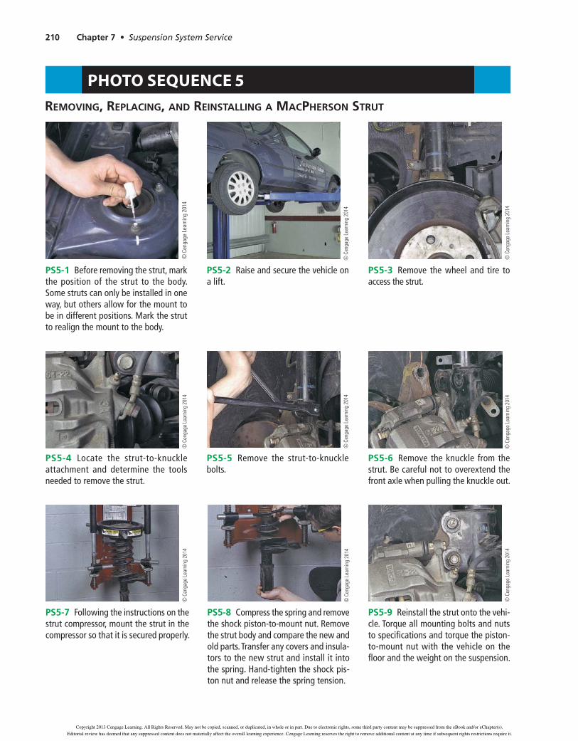
Strut service usually requires removing the strut from the vehicle. Removing a typical MacPherson strut is shown in Photo Sequence 5.
Once the strut is removed, mount it in a strut spring compressor.Useagreasepencilorpaintpentoindexthe mount and coil spring for proper alignment. When it is properly secured and the spring is compressed, remove the nut holding the strut piston rod to the upper bear-ing plate. With the nut removed, slowly remove the strut from the spring and bearing plate. Remove the upper, and inspect it for wear and damage. Inspect the bearing or bushing closely. Worn or damaged strut bearings can cause noise, hard steering, and poor steering return prob-lems. Turn the bearing by hand, and note any roughness. Replace the bearing or mount assembly if there are any signs of excessive wear or damage.
When you are replacing the strut, in many cases, you will need to remove the spring insulator, bumpers, and piston rod cover from the old strut and transfer them to the new unit. The spring insulator goes between the bottom of the coil spring and the spring seat attached to the strut. This insulator helps reduce noise as the spring moves on the strut. Inspect the insulator for damage, and replace it if necessary. The bumper prevents com-pletely collapsing the spring, called bottoming out, on hard impacts. If the bumper shows signs of damage or rot, it should be replaced. Also, inspect the bumper for signs that the spring has been collapsing. The spring itself may show signs of wear as the coils come into con-tact with each other. This can happen as the spring ages
and weakens, allowing the spring to collapse. The piston rod cover protects the piston from damage during opera-tion. Make sure the new strut matches the old strut and reassemble the components.
Install the new strut into the spring and upper mount, and guide the piston through the mounting hole. Place the washer over the piston, and install a new retaining nut. Most struts require the retaining nut to be torqued after the strut is reinstalled on the vehicle and the weight is back on the suspension. It is usually easier to place the upper strut mount into position and install the bolts or nuts to hold the strut assembly when reinstalling. Once the strut is held in place, reattach the lower section of the strut to the steering knuckle. Torque all fasteners to specifications.
Some vehicles have a replaceable shock cartridge. In some vehicles, the strut cartridge can be replaced while the strut is still installed on the vehicle. To replace the cartridge, a special tool kit may be needed to keep the components aligned properly during dis-assembly and reassembly. Always follow the service information for procedures. In general, remove the
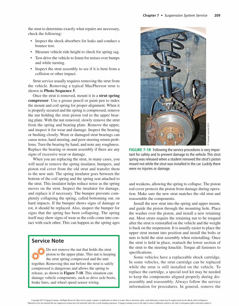
Donotremovethenutthatholdsthestrutpiston to the upper plate. This nut is keeping the strut spring compressed and the unit
together. Removing this nut before the strut is safely compressed is dangerous and allows the spring to release, as shown in Figure 7-18. This situation can damage vehicle components, such as drive axle boots, brake lines, and wheel speed sensor wiring.
Service note
© C
enga
ge L
earn
ing
2014
Figure 7-18 Following the service procedures is very impor-tant for safety and to prevent damage to the vehicle. This strut spring was released when a student removed the strut’s piston mount nut while the strut was installed in the car. Luckily there were no injuries or damage.
39634_ch07_rev02.indd 209 31/01/13 11:02 AM
Copyright 2013 Cengage Learning. All Rights Reserved. May not be copied, scanned, or duplicated, in whole or in part. Due to electronic rights, some third party content may be suppressed from the eBook and/or eChapter(s).
Editorial review has deemed that any suppressed content does not materially affect the overall learning experience. Cengage Learning reserves the right to remove additional content at any time if subsequent rights restrictions require it.
210 Chapter 7 Suspension System Service
PS5-1 Before removing the strut, mark the position of the strut to the body. Some struts can only be installed in one way, but others allow for the mount to be in different positions. Mark the strut to realign the mount to the body.
© C
enga
ge L
earn
ing
2014
PS5-2 Raise and secure the vehicle on a lift.
© C
enga
ge L
earn
ing
2014
PS5-3 Remove the wheel and tire to access the strut.
© C
enga
ge L
earn
ing
2014
PS5-4 Locate the strut-to-knuckle attachment and determine the tools needed to remove the strut.
© C
enga
ge L
earn
ing
2014
PS5-5 Remove the strut-to-knuckle bolts.
© C
enga
ge L
earn
ing
2014
PS5-6 Remove the knuckle from the strut. Be careful not to overextend the front axle when pulling the knuckle out.
© C
enga
ge L
earn
ing
2014
PS5-7 Following the instructions on the strut compressor, mount the strut in the compressor so that it is secured properly.
© C
enga
ge L
earn
ing
2014
PS5-8 Compress the spring and remove the shock piston-to-mount nut. Remove the strut body and compare the new and old parts. Transfer any covers and insula-tors to the new strut and install it into the spring. Hand-tighten the shock pis-ton nut and release the spring tension.
© C
enga
ge L
earn
ing
2014
PS5-9 Reinstall the strut onto the vehi-cle. Torque all mounting bolts and nuts to specifications and torque the piston-to-mount nut with the vehicle on the floor and the weight on the suspension.
© C
enga
ge L
earn
ing
2014
PHOTO SEQUENCE 5REMOVING, REPLACING, AND REINSTALLING A MACPHERSON STRUT
Copyright 201 Cengage Learning. All Rights Reserved. May not be copied, scanned, or duplicated, in whole or in part. Due to electronic rights, some third party content may be suppressed from the eBook and/or eChapter(s).
Editorial review has deemed that any suppressed content does not materially affect the overall learning experience. Cengage Learning reserves the right to remove additional content at any time if subsequent rights restrictions require it.

Chapter 7 • Suspension System Service 211
upper retaining nut and then the cartridge as shown in Figure 7-19. Ensure that the correct amount of oil remains in the strut body when you are replacing the cartridge. The oil is there to remove heat from the shock during operation.
Once the worn components have been replaced, reassemble the strut. Install the upper retaining nut, but do not torque it until the strut is reinstalled on the vehicle and weight is placed on the strut.
When you are replacing gas-charged struts or shocks, the gas charge needs to be released before throwing the strut or shock away. Refer to the shock manufacturer’s service information before attempting to release the pres-sure in the shock as the location and size of hole varies.
In general, to release the gas pressure, a small hole is drilled in the lower section of the strut or shock to allow the gas to escape. The location to drill the hole may be marked on the strut body for reference.
1. Mount in vice
2. Locate cut line
20 mm 3. Remove strut rodand drain oil
4. Flare strut body
5. Install new cartridge
3 grooves on cartridgemust line up with 3 pads in base of reservoir tube
6. Torque new nut
© C
enga
ge L
earn
ing
2014
Figure 7-19 Some struts have replaceable cartridges that can be removed without taking apart the strut.
Donotattempttodepressurizeagasshockor strut without reading and understanding the procedure described in the service
information. Personal injury may result from improper service.
Service note
39634_ch07_rev02.indd 211 31/01/13 11:02 AM
Copyright 2013 Cengage Learning. All Rights Reserved. May not be copied, scanned, or duplicated, in whole or in part. Due to electronic rights, some third party content may be suppressed from the eBook and/or eChapter(s).
Editorial review has deemed that any suppressed content does not materially affect the overall learning experience. Cengage Learning reserves the right to remove additional content at any time if subsequent rights restrictions require it.

212 Chapter 7 • Suspension System Service
Dependingontheageandconditionofthevehicle,replacing the strut assembly may be more cost-effective than repairing it. This is an option to give to the cus-tomer. A replacement assembly contains the entire strut unit, which simplifies the removal and installation.
Shock Inspection and Replacement. Once a shock starts leaking oil or fails to adequately dampen the springs, it should be replaced. In most cases, shock replacement is very straightforward and simple, but always refer to the service information for procedures and tightening specs.
For front shocks on nonstrut vehicles, locate and remove the upper shock mount, then remove the lower shock mount and remove the shock. When you are installing the new shock, be sure to replace the bushings and washers in the correct order, and do not overtighten the bushings. Rear shock replacement is similar but may require the use of a jack to support the rear axle or control arm.
Since shocks are exposed to the outside world, you should expect the mounting hardware to be rusted and possibly frozen into place. Apply a penetrant to the shock mounting bolts and nuts to ease removal. If the hardware is severely rusted, applying heat can often help with removal. Ifavailable,aninductionheater,suchastheMini-Ductor,shown in Figure 7-20, is an excellent tool to heat rusted and seized fasteners. This tool uses high-frequency mag-netic fields flowing through a flexible conductor to heat metal objects. After a few seconds, the metal is heated and can be easily removed without any flames. If, however, this type of tool is not available, you may need to use a traditional torch to apply heat to a fastener.
Install the new shocks and torque all fasteners to specs. Lower the vehicle and bounce each corner of the vehicle. Make sure there are no noises from the shocks as the vehicle is bounced.
Spring Inspection. As suspension springs age they become less capable of supporting the weight of the vehicle; this will cause the vehicle to sag. Locating the
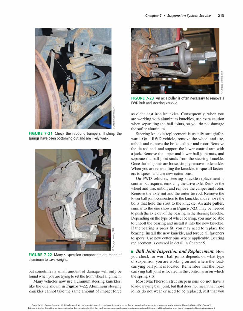
vehicle’s ride height specs and measuring the ride height is the best way to check for weak and sagging springs. Also visually inspect the springs and the rebound bumpers, as shown in Figure 7-21. A bumper that appears shiny means that it has been contacting the frame, which can indicate a weak spring. A rebound bumper that shows damage, such as cracking or chunks missing, should be replaced.
Many vehicles have rubber spring insulators mounted between the spring and the body. These insulators are used to reduce noise when the spring twists slightly as the vehicle jounces and rebounds. Check the insulators to make sure they are intact and positioned correctly between the springs and the frame.
Inspect torsion bars and their mounts. The mounts can deteriorate over time and allow the torsion bar to move. This often causes a clunking noise when going over bumps. Check both the front and rear mounts for damage. Check the crossmember for damage also. Impact damage to the crossmember can affect the rear mount and adjuster.
Steering Knuckles. Steering knuckles are subject to damage from collisions. This is common if the vehicle slides into a curb or other solid object, as sometimes happens in poor weather. Sometimes knuckle damage is obvious,
© C
enga
ge L
earn
ing
2014
Figure 7-20 This tool allows for safe heating of rusted nuts and bolts without causing damage. It uses magnetic induction to excite ferrous metals and create heat.
! Always follow all safety precautions when usinganytypeoftorch.Donotusethetorchwithout proper instruction and supervision.
Donotapplyheattoanychemicalorpenetrant,asafiremayresult.Usingatorchtoheatrustedshockhardware can result in the rubber bushings catching on fire. Be careful to only heat the hardware enough toallowittobreakloose.Donotapplyheatdirectlyto the shock body as the increase in temperature will increase the pressure in the shock. This can cause the shock to burst, causing severe injury and burns.
Safety Warning
39634_ch07_rev02.indd 212 31/01/13 11:02 AM
Copyright 2013 Cengage Learning. All Rights Reserved. May not be copied, scanned, or duplicated, in whole or in part. Due to electronic rights, some third party content may be suppressed from the eBook and/or eChapter(s).
Editorial review has deemed that any suppressed content does not materially affect the overall learning experience. Cengage Learning reserves the right to remove additional content at any time if subsequent rights restrictions require it.
Chapter 7 Suspension System Service 213
but sometimes a small amount of damage will only be found when you are trying to set the front wheel alignment.
Many vehicles now use aluminum steering knuckles, like the one shown in Figure 7-22. Aluminum steering knuckles cannot take the same amount of impact force
as older cast iron knuckles. Consequently, when you are working with aluminum knuckles, use extra caution when separating the ball joints, so you do not damage the softer aluminum.
Steering knuckle replacement is usually straightfor-
unbolt and remove the brake caliper and rotor. Remove the tie rod end, and support the lower control arm with a jack. Remove the upper and lower ball joint nuts, and separate the ball joint studs from the steering knuckle. Once the ball joints are loose, simply remove the knuckle. When you are reinstalling the knuckle, torque all fasten-ers to specs, and use new cotter pins.
similar but requires removing the drive axle. Remove the wheel and tire, unbolt and remove the caliper and rotor. Remove the axle nut and the outer tie rod. Remove the lower ball joint connection to the knuckle, and remove the bolts that hold the strut to the knuckle. An axle puller,similar to the one shown in Figure 7-23, may be needed to push the axle out of the bearing in the steering knuckle.
to unbolt the bearing and install it into the new knuckle. If the bearing is press fit, you may need to replace the bearing. Install the new knuckle, and torque all fasteners
replacement is covered in detail in Chapter 5.
Ball Joint Inspection and Replacement. How you check for worn ball joints depends on what type of suspension you are working on and where the load-carrying ball joint is located. Remember that the load-carrying ball joint is located in the control arm on which the spring sits.
Most MacPherson strut suspensions do not have a load-carrying ball joint, but that does not mean that those joints do not wear or need to be replaced, just that you
© C
enga
ge L
earn
ing
2014
FIGURE 7-21 Check the rebound bumpers. If shiny, the springs have been bottoming out and are likely weak.
© C
enga
ge L
earn
ing
2014
FIGURE 7-22 Many suspension components are made of aluminum to save weight.
© C
enga
ge L
earn
ing
2014
FIGURE 7-23 An axle puller is often necessary to remove a FWD hub and steering knuckle.
Copyright 201 Cengage Learning. All Rights Reserved. May not be copied, scanned, or duplicated, in whole or in part. Due to electronic rights, some third party content may be suppressed from the eBook and/or eChapter(s).
Editorial review has deemed that any suppressed content does not materially affect the overall learning experience. Cengage Learning reserves the right to remove additional content at any time if subsequent rights restrictions require it.

214 Chapter 7 • Suspension System Service
have to check them for wear differently. Figure 7-24 shows how to check the ball joint on a MacPherson strut suspension.
Jacking the vehicle in the correct location unloads the ball joint, so it can be checked for wear and move-ment. To check ball joints on SLA, modified strut, and many multilink systems, jack the vehicle, and support the lower control arm, as shown in Figure 7-25. Place a pry bar under the tire, and pry up against the bottom of the tire. Most ball joints should have zero vertical movement
when checked this way, though there are a some applica-tions that do allow a slight bit of movement. Check the service information for ball joint movement specifica-tions before condemning a slightly loose joint as worn out and needing replaced.
Additionally, even though this has been a typical method of checking ball joint condition, some manufacturers specify checking ball joint wear by measuring the rota-tional torque of the joint using a torque wrench, as shown in Figure 7-26. Always check the service information for
cL
No movementLift point
© C
enga
ge L
earn
ing
2014
Figure 7-24 Check for play in the ball joint by supporting the front end under the frame, not the control arm.
Lift point
Ball jointclearance
© C
enga
ge L
earn
ing
2014
Figure 7-25 Support the lower control arm to check for ball joint wear.
Measure the roationaltorque of the ball jointstud
© C
enga
ge L
earn
ing
2014
Figure 7-26 An excessively worn ball joint will be loose and will have a lower rotational torque than specified.
39634_ch07_rev02.indd 214 31/01/13 11:03 AM
Copyright 2013 Cengage Learning. All Rights Reserved. May not be copied, scanned, or duplicated, in whole or in part. Due to electronic rights, some third party content may be suppressed from the eBook and/or eChapter(s).
Editorial review has deemed that any suppressed content does not materially affect the overall learning experience. Cengage Learning reserves the right to remove additional content at any time if subsequent rights restrictions require it.
Chapter 7 • Suspension System Service 215
testing procedures and specifications before condemning a ball joint.
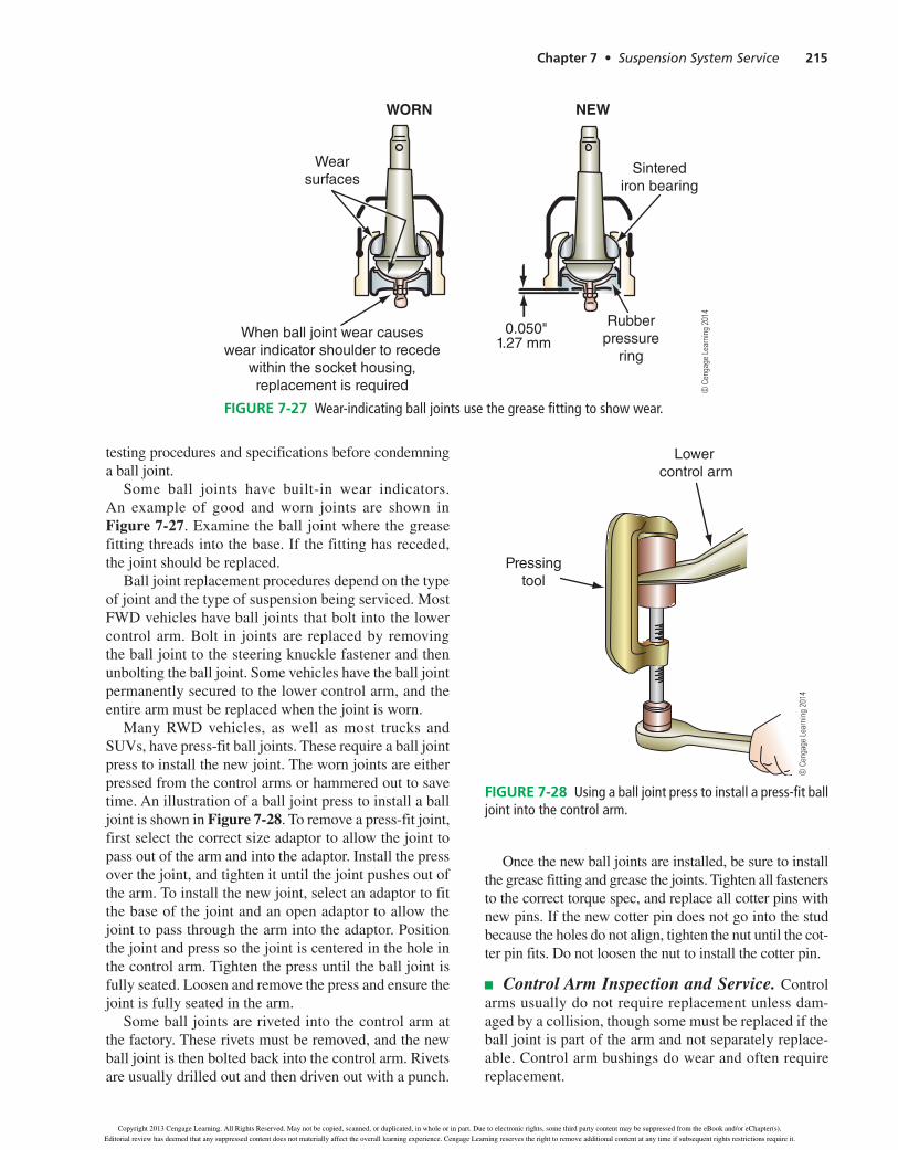
Some ball joints have built-in wear indicators. An example of good and worn joints are shown in Figure 7-27. Examine the ball joint where the grease fitting threads into the base. If the fitting has receded, the joint should be replaced.
Ball joint replacement procedures depend on the type of joint and the type of suspension being serviced. Most FWDvehicleshaveballjointsthatboltintothelowercontrol arm. Bolt in joints are replaced by removing the ball joint to the steering knuckle fastener and then unbolting the ball joint. Some vehicles have the ball joint permanently secured to the lower control arm, and the entire arm must be replaced when the joint is worn.
ManyRWDvehicles, aswell asmost trucks andSUVs,havepress-fitballjoints.Theserequireaballjointpress to install the new joint. The worn joints are either pressed from the control arms or hammered out to save time. An illustration of a ball joint press to install a ball joint is shown in Figure 7-28. To remove a press-fit joint, first select the correct size adaptor to allow the joint to pass out of the arm and into the adaptor. Install the press over the joint, and tighten it until the joint pushes out of the arm. To install the new joint, select an adaptor to fit the base of the joint and an open adaptor to allow the joint to pass through the arm into the adaptor. Position the joint and press so the joint is centered in the hole in the control arm. Tighten the press until the ball joint is fully seated. Loosen and remove the press and ensure the joint is fully seated in the arm.
Some ball joints are riveted into the control arm at the factory. These rivets must be removed, and the new ball joint is then bolted back into the control arm. Rivets are usually drilled out and then driven out with a punch.
Once the new ball joints are installed, be sure to install the grease fitting and grease the joints. Tighten all fasteners to the correct torque spec, and replace all cotter pins with new pins. If the new cotter pin does not go into the stud because the holes do not align, tighten the nut until the cot-terpinfits.Donotloosenthenuttoinstallthecotterpin.
Control Arm Inspection and Service. Control arms usually do not require replacement unless dam-aged by a collision, though some must be replaced if the ball joint is part of the arm and not separately replace-able. Control arm bushings do wear and often require replacement.
Lower control arm
Pressingtool
© C
enga
ge L
earn
ing
2014
WORN NEW
Sinterediron bearing
Rubberpressure
ring
Wearsurfaces
When ball joint wear causeswear indicator shoulder to recede
within the socket housing,replacement is required
0.050"1.27 mm
© C
enga
ge L
earn
ing
2014
Figure 7-27 Wear-indicating ball joints use the grease fitting to show wear.
Figure 7-28 Using a ball joint press to install a press-fit ball joint into the control arm.
39634_ch07_rev02.indd 215 31/01/13 11:03 AM
Copyright 2013 Cengage Learning. All Rights Reserved. May not be copied, scanned, or duplicated, in whole or in part. Due to electronic rights, some third party content may be suppressed from the eBook and/or eChapter(s).
Editorial review has deemed that any suppressed content does not materially affect the overall learning experience. Cengage Learning reserves the right to remove additional content at any time if subsequent rights restrictions require it.
216 Chapter 7 • Suspension System Service
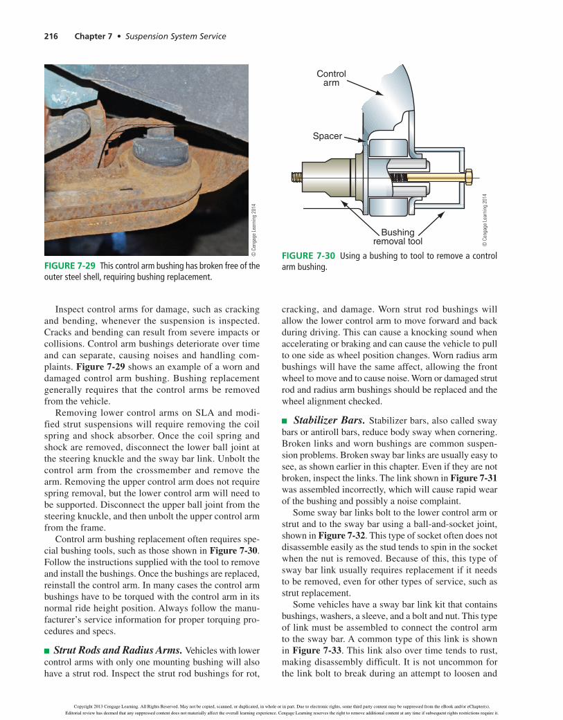
Inspect control arms for damage, such as cracking and bending, whenever the suspension is inspected. Cracks and bending can result from severe impacts or collisions. Control arm bushings deteriorate over time and can separate, causing noises and handling com-plaints. Figure 7-29 shows an example of a worn and damaged control arm bushing. Bushing replacement generally requires that the control arms be removed from the vehicle.
Removing lower control arms on SLA and modi-fied strut suspensions will require removing the coil spring and shock absorber. Once the coil spring and shock are removed, disconnect the lower ball joint at thesteeringknuckleandtheswaybarlink.Unboltthecontrol arm from the crossmember and remove the arm. Removing the upper control arm does not require spring removal, but the lower control arm will need to besupported.Disconnecttheupperballjointfromthesteering knuckle, and then unbolt the upper control arm from the frame.
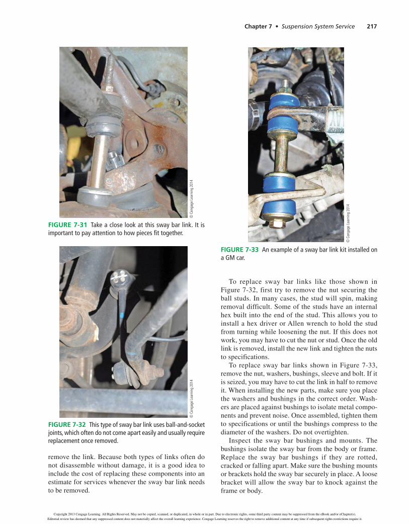
Control arm bushing replacement often requires spe-cial bushing tools, such as those shown in Figure 7-30. Follow the instructions supplied with the tool to remove and install the bushings. Once the bushings are replaced, reinstall the control arm. In many cases the control arm bushings have to be torqued with the control arm in its normal ride height position. Always follow the manu-facturer’s service information for proper torquing pro-cedures and specs.
Strut Rods and Radius Arms. Vehicles with lower control arms with only one mounting bushing will also have a strut rod. Inspect the strut rod bushings for rot,
cracking, and damage. Worn strut rod bushings will allow the lower control arm to move forward and back during driving. This can cause a knocking sound when accelerating or braking and can cause the vehicle to pull to one side as wheel position changes. Worn radius arm bushings will have the same affect, allowing the front wheel to move and to cause noise. Worn or damaged strut rod and radius arm bushings should be replaced and the wheel alignment checked.
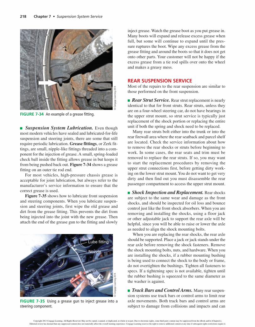
Stabilizer Bars. Stabilizer bars, also called sway bars or antiroll bars, reduce body sway when cornering. Broken links and worn bushings are common suspen-sion problems. Broken sway bar links are usually easy to see, as shown earlier in this chapter. Even if they are not broken, inspect the links. The link shown in Figure 7-31 was assembled incorrectly, which will cause rapid wear of the bushing and possibly a noise complaint.
Some sway bar links bolt to the lower control arm or strut and to the sway bar using a ball-and-socket joint, shown in Figure 7-32. This type of socket often does not disassemble easily as the stud tends to spin in the socket when the nut is removed. Because of this, this type of sway bar link usually requires replacement if it needs to be removed, even for other types of service, such as strut replacement.
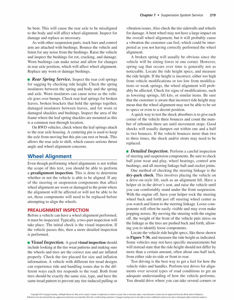
Some vehicles have a sway bar link kit that contains bushings, washers, a sleeve, and a bolt and nut. This type of link must be assembled to connect the control arm to the sway bar. A common type of this link is shown in Figure 7-33. This link also over time tends to rust, making disassembly difficult. It is not uncommon for the link bolt to break during an attempt to loosen and
© C
enga
ge L
earn
ing
2014
Figure 7-29 This control arm bushing has broken free of the outer steel shell, requiring bushing replacement.
Controlarm
Spacer
Bushingremoval tool ©
Cen
gage
Lea
rnin
g 20
14
Figure 7-30 Using a bushing to tool to remove a control arm bushing.
39634_ch07_rev02.indd 216 31/01/13 11:03 AM
Copyright 2013 Cengage Learning. All Rights Reserved. May not be copied, scanned, or duplicated, in whole or in part. Due to electronic rights, some third party content may be suppressed from the eBook and/or eChapter(s).
Editorial review has deemed that any suppressed content does not materially affect the overall learning experience. Cengage Learning reserves the right to remove additional content at any time if subsequent rights restrictions require it.
Chapter 7 Suspension System Service 217
remove the link. Because both types of links often do not disassemble without damage, it is a good idea to include the cost of replacing these components into an estimate for services whenever the sway bar link needs to be removed.
To replace sway bar links like those shown in Figure 7-32, first try to remove the nut securing the ball studs. In many cases, the stud will spin, making removal difficult. Some of the studs have an internal hex built into the end of the stud. This allows you to install a hex driver or Allen wrench to hold the stud from turning while loosening the nut. If this does not work, you may have to cut the nut or stud. Once the old link is removed, install the new link and tighten the nuts to specifications.
To replace sway bar links shown in Figure 7-33, remove the nut, washers, bushings, sleeve and bolt. If it is seized, you may have to cut the link in half to remove it. When installing the new parts, make sure you place the washers and bushings in the correct order. Wash-ers are placed against bushings to isolate metal compo-nents and prevent noise. Once assembled, tighten them to specifications or until the bushings compress to the
Inspect the sway bar bushings and mounts. The bushings isolate the sway bar from the body or frame. Replace the sway bar bushings if they are rotted, cracked or falling apart. Make sure the bushing mounts or brackets hold the sway bar securely in place. A loose bracket will allow the sway bar to knock against the frame or body.
© C
enga
ge L
earn
ing
2014
FIGURE 7-31 Take a close look at this sway bar link. It is important to pay attention to how pieces fit together.
© C
enga
ge L
earn
ing
2014
FIGURE 7-32 This type of sway bar link uses ball-and-socket joints, which often do not come apart easily and usually require replacement once removed.
© C
enga
ge L
earn
ing
2014
FIGURE 7-33 An example of a sway bar link kit installed on a GM car.
Copyright 201 Cengage Learning. All Rights Reserved. May not be copied, scanned, or duplicated, in whole or in part. Due to electronic rights, some third party content may be suppressed from the eBook and/or eChapter(s).
Editorial review has deemed that any suppressed content does not materially affect the overall learning experience. Cengage Learning reserves the right to remove additional content at any time if subsequent rights restrictions require it.
218 Chapter 7 • Suspension System Service
Suspension System Lubrication. Even though most modern vehicles have sealed and lubricated-for-life suspension and steering joints, there are some that still require periodic lubrication. Grease fittings, or Zerk fit-tings, are small, nipple-like fittings threaded into a com-ponent for the injection of grease. A small, spring-loaded check ball inside the fitting allows grease in but keeps it from being pushed back out. Figure 7-34 shows a grease fitting on an outer tie rod end.
For most vehicles, high-pressure chassis grease is acceptable for joint lubrication, but always refer to the manufacturer’s service information to ensure that the correct grease is used.
Figure 7-35 shows how to lubricate front suspension and steering components. When you lubricate suspen-sion and steering joints, first wipe the old grease and dirt from the grease fitting. This prevents the dirt from being injected into the joint with the new grease. Then attach the end of the grease gun to the fitting and slowly
inject grease. Watch the grease boot as you put grease in. Many boots will expand and release excess grease when full, but some will continue to expand until the pres-sure ruptures the boot. Wipe any excess grease from the grease fitting and around the boots so that it does not get onto other parts. Your customer will not be happy if the excess grease from a tie rod spills over onto the wheel and makes a greasy mess.
reAr SuSpenSion ServiCeMost of the repairs to the rear suspension are similar to those performed on the front suspension.
Rear Strut Service. Rear strut replacement is nearly identical to that for front struts. Rear struts, unless they are on a four-wheel steering car, do not have bearings in the upper strut mount, so strut service is typically just replacement of the shock portion or replacing the entire unit if both the spring and shock need to be replaced.
Many rear struts bolt either into the trunk or into the rear firewall area where the rear seatback and parcel shelf are located. Check the service information about how to remove the rear shocks or struts before beginning to work. In some cases, the rear seats and trim must be removed to replace the rear struts. If so, you may want to start the replacement procedures by removing the upper strut connections first, before getting dirty work-ing on the lower strut mount. You do not want to get very dirty and then find out you must disassemble the rear passenger compartment to access the upper strut mount.
Shock Inspection and Replacement. Rear shocks are subject to the same wear and damage as the front shocks, and should be inspected for oil loss and bounce control just like the front shock absorbers. When you are removing and installing the shocks, using a floor jack or other adjustable jack to support the rear axle will be helpful, since you will be able to raise or lower the axle as needed to align the shock mounting bolts.
When you are replacing the rear shocks, the rear axle should be supported. Place a jack or jack stands under the rear axle before removing the shock fasteners. Remove the shock mounting bolts, nuts, and hardware. When you are installing the shocks, if a rubber mounting bushing is being used to connect the shock to the body or frame, do not overtighten the bushings. Tighten all fasteners to specs. If a tightening spec is not available, tighten until the rubber bushing is squeezed to the same diameter as the washer is against.
Track Bars and Control Arms. Many rear suspen-sion systems use track bars or control arms to limit rear axle movements. Both track bars and control arms are subject to damage from collisions and impacts and can
© C
enga
ge L
earn
ing
2014
Figure 7-34 An example of a grease fitting.
Lube fitting
Nozzle
© C
enga
ge L
earn
ing
2014
Figure 7-35 Using a grease gun to inject grease into a steering component.
39634_ch07_rev02.indd 218 31/01/13 11:03 AM
Copyright 2013 Cengage Learning. All Rights Reserved. May not be copied, scanned, or duplicated, in whole or in part. Due to electronic rights, some third party content may be suppressed from the eBook and/or eChapter(s).
Editorial review has deemed that any suppressed content does not materially affect the overall learning experience. Cengage Learning reserves the right to remove additional content at any time if subsequent rights restrictions require it.
Chapter 7 • Suspension System Service 219
be bent. This will cause the rear axle to be misaligned to the body and will affect wheel alignment. Inspect for damage and replace as necessary.
As with other suspension parts, track bars and control arm are attached with bushings. Bounce the vehicle and listen for any noise from the bushings. Raise the vehicle and inspect the bushings for rot, cracking, and damage. Worn bushings can make noise and allow for changes in rear axle position, which will affect wheel alignment. Replace any worn or damage bushings.
Rear Spring Service. Inspect the rear coil springs for sagging by checking ride height. Check the spring insulators between the spring and body and the spring and axle. Worn insulators can cause noise as the vehi-cle goes over bumps. Check rear leaf springs for broken leaves, broken brackets that hold the springs together, damaged insulators between leaves, and for worn or damaged shackles and bushings. Inspect the area of the frame where the leaf spring shackles are mounted as this is a common rust-through location.
OnRWDvehicles,checkwheretheleafspringsattachto the rear axle housing. A centering pin is used to keep the axle from moving but this pin can rust or break. This allows the rear axle to shift, which causes serious thrust angle and wheel alignment concerns.
Wheel AlignmentEven though performing wheel alignments is not within the scope of this text, you should be able to perform a prealignment inspection. This is done to determine whether or not the vehicle is able to be aligned. If any of the steering or suspension components that affect wheel alignment are worn or damaged to the point where the alignment will be affected or will not be able to be set, those components will need to be replaced before attempting to align the wheels.
preAlignmenT inSpeCTionBefore a vehicle can have a wheel alignment performed, it must be inspected. Typically, a two-part inspection will take place. The initial check is the visual inspection. If the vehicle passes this, then a more detailed inspection is performed.
Visual Inspection. A good visual inspection should include looking at the tire wear patterns and making sure the wheels and tires are the correct size and are inflated properly. Check the tire placard for size and inflation information. A vehicle with different tire tread designs can experience ride and handling issues due to the dif-ferent ways each tire responds to the road. Both front tires should be exactly the same size, type, and have the same tread pattern to prevent any tire-induced pulling or
vibration issues. Also check the tire sidewalls and wheels for damage. A bent wheel may not have a large impact on the overall wheel alignment, but it will probably cause a vibration the customer can feel, which could be inter-preted as you not having correctly performed the wheel alignment.
A broken spring will usually be obvious since the vehicle will be sitting lower in one corner. However, spring sag that occurs over time is generally not as noticeable. Locate the ride height specs, and measure the ride height. If the height is incorrect, either too high from vehicle modifications or too low from modifica-tions or weak springs, the wheel alignment will prob-ably be affected. Check for signs of modifications, such as lowering springs, lift kits, or similar items. Be sure that the customer is aware that incorrect ride height may mean that the wheel alignment may not be able to be set to specs or even to a decent position.
A quick way to test the shock absorbers is to give each corner of the vehicle three bounces and count the num-berofreboundsthereareuntilmovementstops.Goodshocks will usually dampen out within one and a half to two bounces. If the vehicle bounces more than two to three times, the shock and/or struts may need to be replaced.
Detailed Inspection. Perform a careful inspection of steering and suspension components. Be sure to check ball joint wear and play, wheel bearings, control arm bushings, and all steering linkage ball-and-socket joints.
One method of checking the steering linkage is the dry-park check. This involves placing the vehicle on a drive-on-style lift, such as an alignment lift. Have a helper sit in the driver’s seat, and raise the vehicle until you can comfortably stand under the front suspension. With the engine off, have your helper rock the steering wheel back and forth just off steering wheel center as you watch and listen to the steering linkage. Loose com-ponents will often be easily visible and may even make popping noises. By moving the steering with the engine off, the weight of the front of the vehicle puts stress on the linkage as the tires are pushed back and forth, allow-ing you to identify loose components.
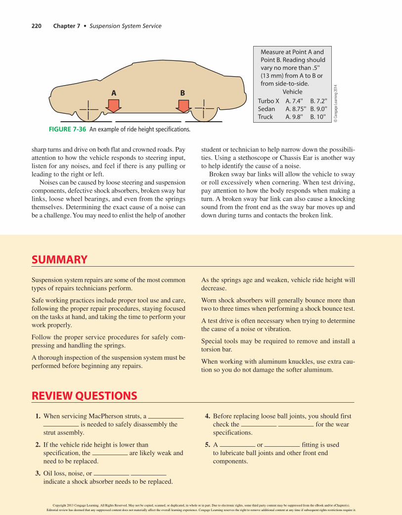
Locate the vehicle ride height specs, like those shown in Figure 7-36, and measure the ride height as indicated. Some vehicles may not have specific measurements but will instead state that the ride height should not differ by more than a certain amount, often about one-half inch, from either side-to-side or front to rear.
Test driving is the best way to get a feel for how the vehicle rides and handles. Perform test drives for align-ments over several types of road conditions to get an adequate understanding of how the vehicle performs. You should drive where you can take several corners or
39634_ch07_rev02.indd 219 31/01/13 11:03 AM
Copyright 2013 Cengage Learning. All Rights Reserved. May not be copied, scanned, or duplicated, in whole or in part. Due to electronic rights, some third party content may be suppressed from the eBook and/or eChapter(s).
Editorial review has deemed that any suppressed content does not materially affect the overall learning experience. Cengage Learning reserves the right to remove additional content at any time if subsequent rights restrictions require it.
220 Chapter 7 • Suspension System Service
sharp turns and drive on both flat and crowned roads. Pay attention to how the vehicle responds to steering input, listen for any noises, and feel if there is any pulling or leading to the right or left.
Noises can be caused by loose steering and suspension components, defective shock absorbers, broken sway bar links, loose wheel bearings, and even from the springs themselves.Determiningtheexactcauseofanoisecanbe a challenge. You may need to enlist the help of another
student or technician to help narrow down the possibili-ties.UsingastethoscopeorChassisEarisanotherwayto help identify the cause of a noise.
Broken sway bar links will allow the vehicle to sway or roll excessively when cornering. When test driving, pay attention to how the body responds when making a turn. A broken sway bar link can also cause a knocking sound from the front end as the sway bar moves up and down during turns and contacts the broken link.
© C
enga
ge L
earn
ing
2014
Measure at Point A and Point B. Reading shouldvary no more than .5''(13 mm) from A to B orfrom side-to-side.
VehicleTurbo XSedanTruck
A. 7.4''A. 8.75''A. 9.8''
B. 7.2''B. 9.0''B. 10''
A B
Figure 7-36 An example of ride height specifications.
SuMMARY
Suspension system repairs are some of the most common types of repairs technicians perform.
Safe working practices include proper tool use and care, following the proper repair procedures, staying focused on the tasks at hand, and taking the time to perform your work properly.
Follow the proper service procedures for safely com-pressing and handling the springs.
A thorough inspection of the suspension system must be performed before beginning any repairs.
As the springs age and weaken, vehicle ride height will decrease.
Worn shock absorbers will generally bounce more than two to three times when performing a shock bounce test.
A test drive is often necessary when trying to determine the cause of a noise or vibration.
Special tools may be required to remove and install a torsion bar.
When working with aluminum knuckles, use extra cau-tion so you do not damage the softer aluminum.
REVIEW quESTIonS
1. When servicing MacPherson struts, a is needed to safely disassembly the
strut assembly.
2. If the vehicle ride height is lower than specification, the are likely weak and need to be replaced.
3. Oil loss, noise, or indicate a shock absorber needs to be replaced.
4. Before replacing loose ball joints, you should first check the for the wear specifications.
5. A or fitting is used to lubricate ball joints and other front end components.
39634_ch07_rev02.indd 220 31/01/13 11:03 AM
Copyright 2013 Cengage Learning. All Rights Reserved. May not be copied, scanned, or duplicated, in whole or in part. Due to electronic rights, some third party content may be suppressed from the eBook and/or eChapter(s).
Editorial review has deemed that any suppressed content does not materially affect the overall learning experience. Cengage Learning reserves the right to remove additional content at any time if subsequent rights restrictions require it.

Chapter 7 • Suspension System Service 221
9. Technician A says if a vehicle’s ride height is below specifications, a wheel alignment can still be performed. Technician B says if ride height is too low, the shocks and springs are weak and need to be replaced. Who is correct?
a. Technician A c. Both A and B
b. Technician B d. Neither A nor B
10. All of the following statements about front suspensions are correct except:
a. Most strut suspensions eliminate the upper control arm and ball joint.
b. The load-carrying ball joint is in the control arm on which the spring sits.
c. The load-carrying ball joint on a MacPherson strut suspension is the lower joint.
d. The nonload-carrying ball joint is called a following ball joint.
6. Technician A says most front suspension springs are coil springs. Technician B says some vehicles use torsion bars as the front springs. Who is correct?
a. Technician A c. Both A and B
b. Technician B d. Neither A nor B
7. A knocking sound from the front suspension is heard during turns: Technician A says a broken sway bay link may be the cause. Technician B says a worn sway bar bushing may be the cause. Who is correct?
a. Technician A c. Both A and B
b. Technician B d. Neither A nor B
8. AFWDvehiclehasbeeninacollision,andtheleft front wheel is notably leaning in at the top: Technician A says the steering knuckle may be damaged. Technician B says the lower control arm is bent. Who is correct?
a. Technician A c. Both A and B
b. Technician B d. Neither A nor B
Chapter 7 • Suspension System Service 221
39634_ch07_rev02.indd 221 31/01/13 11:03 AM
Copyright 2013 Cengage Learning. All Rights Reserved. May not be copied, scanned, or duplicated, in whole or in part. Due to electronic rights, some third party content may be suppressed from the eBook and/or eChapter(s).
Editorial review has deemed that any suppressed content does not materially affect the overall learning experience. Cengage Learning reserves the right to remove additional content at any time if subsequent rights restrictions require it.