sustaining high energy efficiency in existing processes
TRANSCRIPT

Applied Energy xxx (2012) xxx–xxx
Contents lists available at SciVerse ScienceDirect
Applied Energy
journal homepage: www.elsevier .com/locate /apenergy
Sustaining high energy efficiency in existing processes with advancedprocess integration technology
Nan Zhang a,b,⇑, Robin Smith a,b, Igor Bulatov a, Jirí Jaromír Klemeš c
a Centre for Process Integration, School of Chemical Engineering and Analytical Science, The University of Manchester, Manchester M13 9PL, UKb Process Integration Limited, One Central Park, Northampton Road, Monsall, Manchester M40 5BP, UKc Centre for Process Integration and Intensification – CPI2, Research Institute of Chemical and Process Engineering, Faculty of Information Technology,University of Pannonia, Egyetem u. 10, Veszprém 8200, Hungary
a r t i c l e i n f o a b s t r a c t
Article history:Received 13 December 2011Received in revised form 2 February 2012Accepted 8 February 2012Available online xxxx
Keywords:Process integrationOperation optimisationHeat integrated distillation
0306-2619/$ - see front matter � 2012 Elsevier Ltd. Adoi:10.1016/j.apenergy.2012.02.037
⇑ Corresponding author at: Centre for Process IntEngineering and Analytical Science, The University of M9PL, UK.
E-mail address: [email protected] (N. Z
Please cite this article in press as: Zhang N et al.Energy (2012), doi:10.1016/j.apenergy.2012.02.
To reduce emissions in the process industry, much emphasis has been put on making step changes inemission reduction, by developing new process technology and making renewable energy more afford-able. However, the energy saving potential of existing systems cannot be simply ignored. In recent years,there have been significant advances in process integration technology with better modelling techniquesand more advanced solution methods. These methods have been applied to the new design and retrofitstudies in the process industry. Here attempts are made to apply these technologies to improve the envi-ronmental performance of existing facilities with operational changes. An industrial project was carriedout to demonstrate the importance and effectiveness of exploiting the operational flexibility for energyconservation. By applying advanced optimisation technique to integrate the operation of distillationand heat recovery in a crude oil distillation unit, the energy consumption was reduced by 8% without cap-ital expenditure. It shows that with correctly identified technology and the proper execution procedure,significant energy savings and emission reduction can be achieved very quickly without major capitalexpenditure. This allows the industry to improve its economic and environment performance at the sametime.
� 2012 Elsevier Ltd. All rights reserved.
1. Introduction
The process industry is facing a great challenge to reduce theiremissions while maintaining their competitiveness in the marketeconomy. Much emphasis has been put on making step changesin emission reduction, by developing new process technologyand making renewable energy more affordable. However, it wouldbe a mistake if the flexibility of existing systems is not exploitedfully in order to improve their energy performance.
Traditionally, the technology development of process integra-tion has been mainly focused on the synthesis problems of processflow sheets in the chemical industry, with significant emphasis onenergy conservation. Built on the early generation graphical ap-proaches such as pinch analysis [1,2], in recent years, there havebeen significant advances in process integration technology [3].Extension of the original pinch analysis, better modelling tech-niques and more advanced solution methods allow very compli-cated networks to be optimised at a much detailed level, with
ll rights reserved.
egration, School of Chemicalanchester, Manchester M13
hang).
Sustaining high energy efficienc037
typical examples in separation systems [4], heat recovery networks[5,6], utility systems [7], and total site analysis [8,9]. Many of thesemethods have been widely applied to the industry, to allow de-signs and retrofit studies to maximise the energy recovery[10,11] and reduce CO2 emissions by improved process efficiency[12] and by process integration [13,14]. But the attempts of apply-ing these technologies to improve the energy and environmentalperformance of existing facilities with operational changes are lim-ited, due to major obstacles to bridge research outcomes withindustrial applications, even though preliminaries academic calcu-lations normally show significant savings could be achieved.
Through industrial demonstration projects, there are two mainissues that have been highlighted to bridge the gaps: identificationof suitable technologies, and practical and precise implementationstrategies.
2. Technology identification
There are two key aspects in exploiting the potential of energyefficiency improvement in existing chemical processes. One is fromindividual unit operations, with the focus on better equipmentdesign and optimal operating conditions. The other one is to inte-grate unit operations as a whole, using system engineering/process
y in existing processes with advanced process integration technology. Appl
2 N. Zhang et al. / Applied Energy xxx (2012) xxx–xxx
integration technology. Therefore, the discussion here will be fo-cused on the latter aspect.
The constitution of chemical processes is best explained by theso-called ‘‘onion diagram’’ [15], shown in Fig. 1. It starts at theheart of the onion with the reactor and then moves outwards tothe following layers: the separation system, the heat recovery sys-tem and the utility system.
In terms of energy conservation in chemical processes, eachlayer in the onion diagram has specific technical aspects to con-sider. In addition, there are certain interactions between these lay-ers. Various process integration techniques have been developed toaddress these aspects, with typical examples mentioned in theIntroduction. Such developments make it possible for us to lookinto the possibility of exploiting the potential of improving energyefficiency of existing systems with better operating strategies.
For operation optimisation, the problem can be considered as asubset of a new design problem for the same process. The essentialinternal physical models can remain the same as the ones for de-sign and retrofit purposes, with additional constraints on equip-ment and operating conditions. However, these models can onlybe applicable to operation optimisation under three conditions:there are operating variables that can be manipulated to vary theenergy performance of the process under investigation; the modelscan accurately reflect the performance variations of unit opera-tions; and the computation time is sufficiently short to meet therequirement of operation monitoring and management. The threecriteria have to be examined when it comes to the technologyidentification for system operation improvement. To illustratethese points, let us take a crude oil distillation process as anexample.
Fig. 2 shows a typical flow sheet of a crude oil distillation unit.There are two main sections that are of our interest in the flowsheet. One is the distillation system, including an atmospheric dis-tillation column, a vacuum distillation column, and a number ofstripping columns for side-draw products. There are also pump-arounds attached to the two main columns to remove heat at dif-ferent temperature level and provide intermediate reflux. Theother section is a heat exchanger network that achieves heat recov-ery by exchanging heat between the cold crude oil and hot productstreams and pumparounds. Both sections have been a subject ofinvestigation in the area of process integration since 1980s, andwe have seen significant progress made in process design and ret-rofit to achieve energy conservation. Early methods were mainlybased on thermodynamic principles for heat integration [2] andshort-cut models for distillation system design [16]. They provideduseful physical insights of the system energy efficiency andsystematic approaches for conceptual design. However, the lackof accuracy makes these methods unsuitable for operationoptimisation.
Due to improved solution methods and advances in computingtechnology, more accurate unit models have been developed and
Fig. 1. ‘‘Onion diagram’’ of chemical processes.
Please cite this article in press as: Zhang N et al. Sustaining high energy efficiencEnergy (2012), doi:10.1016/j.apenergy.2012.02.037
larger network models have been constructed and solved. Forexample, semi-rigorous distillation models have been developedfor complex separation systems to replace short-cut models to im-prove the model accuracy [4]. For design of heat exchanger net-works, the application of simulated annealing [17] into thesolution method has vastly improved the quality of design solu-tions [18]. The issue of result accuracy seems no longer the bottle-neck of operation optimisation. However, very few efforts havebeen made to apply these technologies for operation optimisation.
Under a fixed process configuration, the impact of changingoperating conditions on energy efficiency may not be clear whena distillation system or a heat exchanger network is investigatedindividually using process integration techniques. In addition, anexisting heat exchanger network itself has very limited optionsfor changing its operating conditions at all. Therefore, these tech-nologies along are not suitable for operation optimisation of sucha process. The interactions between distillation operation and heatrecovery has to be exploited simultaneously with their individualoperating parameters, as shown in Fig. 3.
In this case, the key operating variables that affect the energyefficiency are the pumparound duties in both the atmosphericand the vacuum distillation columns, which have significant effectson both product qualities and heat recovery performance. In otherwords, pumparound duties are the key link between distillationoperation and heat recovery. Therefore, in order to improve the en-ergy efficiency by operation optimisation of crude oil distillationprocesses, it is essential that distillation and heat recovery can beoptimised at the same time.
An integrated optimisation approach has been developed toachieve just that [5]. The detailed approach is shown in Fig. 4.There are two key technology advances in this approach. The firsttechnology advance is a semi-rigorous modelling method for com-plex distillation systems. The method is still based on the decom-position method developed to simplify the calculation of complexdistillation systems, as shown in Fig. 5. A series of simple columnsare solved to provide better computation speed and convergence.The errors caused by the assumption of constant molar vapour/li-quid flow in the traditional short-cut distillation model need tobe corrected, while the expensive computation time with the rigor-ous stage-by-stage method commonly used in commercial simula-tion packages such as AspenPlus [19] and ProII [20] needs to beavoided. Therefore, a middle-way approach is adopted. The mass/energy balance calculation for an overall distillation column aswell as the key stages at the top and the bottom of each simple col-umn under certain product specifications is incorporated into theshort-cut model, as shown in Fig. 6 [5].
The second key technical advance is the integrated optimisationbetween distillation systems and heat recovery systems. The sim-ulated annealing approach used for heat exchanger network opti-misation [18] has been extended to cover both distillationoptimisation variables and heat recovery variables, as shown inFig. 7. Each move represents the change of each optimisation var-iable. Under the current computation power, this approach is onlymade feasible because of the developed semi-rigorous distillationmodel. The conventional short-cut model is not accurate enoughto capture the interactions between distillation and heat recovery,while the rigorous stage-by-stage method is too time-consumingto be used in simulated annealing. Due to the random nature ofthe simulated annealing algorithm, each run may give a slightlydifferent solution, which is why there is a need of multiple runsof simulated annealing to ensure the quality of the solution, asindicated in Fig. 4.
As can be seen in Fig. 7, key operating parameters such as re-flux/reboiling, pumparound conditions, and heat exchanger duties,and their impact on product recovery are taken into considerationin this approach and can then be optimised simultaneously. This
y in existing processes with advanced process integration technology. Appl

Light VacuumGas Oil
Heavy VacuumGas Oil
Steam Ejectors NoncondensibleGas
Water
Vacuum Residue(Short Residue, Asphalt)
Steam
Steam
Steam
cw cw cw
cw
HeatRecovery
HeatRecovery
Steam
Steam
CrudeOil
Desalter
Furnace(Pipestill)
Light Ends
WaterLight Naphtha
AtmosphericGas oil
SR Diesel
SR Kerosene
SR HeavyNaphtha
Fig. 2. Simplified flow sheet of crude oil distillation process.
WaterLN
HN
LD
SteamHD
Steam
RES
UPA
MPA
Feed
Steam
LPA
Column operation Heat recovery system operation
Interactions
Fig. 3. Interactions between distillation and heat recovery.
Cost Models
Distillation ColumnHydraulic Model(s)
Cost penalty function tocompensate for the infeasible
column design in terms ofproduct specifications
Multi-segmentedHEN Model
Distillation Column Models
Simulation Model
MINLP Optimiser (Multiple simulated
Annealing)
Process with existing operatingconditions, distillation columns
and HEN structure
ParameterBoundaries
Constraints:Product propertyspecificationsExisting ColumnsExisting HEN
Process with optimum operating conditions,distillation columns and HEN structure
Objectivefunction
Fig. 4. Integration optimisation method for complex distillation systems.
N. Zhang et al. / Applied Energy xxx (2012) xxx–xxx 3
makes it possible to be applied to operation optimisation for suchcomplex separation systems. However, it is not so straightforwardto achieve this goal. Extra care has to be taken in order to avoid
Please cite this article in press as: Zhang N et al. Sustaining high energy efficiencEnergy (2012), doi:10.1016/j.apenergy.2012.02.037
mis-calculations that can cause severe operation upsets and eco-nomic losses. Therefore, a systematic procedure is needed for suchtechnology implementation.
y in existing processes with advanced process integration technology. Appl

LN
HN
LD
SteamHD
Steam
Atmospheric Residue
Crude
PA1
PA2
PA3
Water
HVGO
LVGO
Steam
Vapour to steam ejector
Vacuum Residue
Decomposed sequence foroptimisation
HVGO
6
5
LVGO
7
Vacuum Residue
Vapour
Atm. Residue
HD
LD
HN
LN
Crude1
2
3
4
PA1
PA2
PA3
Fig. 5. Decomposition of complex distillation systems.
Fig. 6. Simple column modelling with product specifications.
4 N. Zhang et al. / Applied Energy xxx (2012) xxx–xxx
3. Systematic implementation strategy
It is a common sense that we cannot put a blind trust on anymodel predictions no matter how good a model is supposed tobe. However, it is not straightforward to match any model predic-tion to the reality and then provide valid instructions for improve-ment. There are four key stages in systematic implementation(Fig. 8): data collection, model development, model validation,and optimisation implementation.
Both operating data and design data are required in data collec-tion. It is easy to understand why operating data such as tempera-tures, pressures, flow rates, and feed/product properties arerequired. The importance of collecting design data needs to behighlighted. Setting boundaries for practical constraints is criticallyimportant in formulating optimisation problems and obtainingsensible solutions. In order to identify correct boundaries on equip-ment performance and throughput limit, detailed design data ofdistillation columns and heat exchangers are needed to set out
Please cite this article in press as: Zhang N et al. Sustaining high energy efficiencEnergy (2012), doi:10.1016/j.apenergy.2012.02.037
clear restrictions on column hydraulics and heat transfer capabili-ties of heat exchangers.
In model development, while the model building for heatexchangers is relatively straightforward, the model building fordistillation is more challenging. To develop a semi-rigorous distil-lation model that is required in optimisation, a rigorous simulationmodel has to be developed first in order to reconcile the semi-rig-orous model against the actual operation. The rigorous model gen-erates essential information of detailed mass and energy balancewithin a distillation column, which is required to establish thesemi-rigorous model. Therefore, it acts as a necessary link betweenthe operating data and the optimisation model.
Both distillation models and heat exchanger models need to beverified before optimisation. This is the stage for data reconcilia-tion and model updating. The rigorous distillation model can helpto identify faulty measurements based on the fundamental princi-ples of mass/energy balance and thermodynamics. However, forsuch a large and complex system, it is important to take into ac-count the experience of operators, who can be very helpful to iden-tify key potential problems that can cause mismatches. Still, it isquite common that several iterations between data collectionand model building are required before an optimisation modelcan be satisfactorily verified. A close involvement of operating per-sonnel can make this process more efficient.
Even with a reasonable looking optimisation model, extremecaution is required in implementation of optimisation results.
Firstly, suitable operating parameters must be identified foroperation changes. Operation optimisation is only possible if suchparameters are available. Secondly, process constraints need to beclearly defined and verified, in order to maintain product qualitiesand stability of process operation. For instance, column hydrauliccalculations are required to set the limits on liquid and vapourflows within a distillation column in order not to cause operatingupsets.
Thirdly, optimal operating strategy can then be determinedusing the developed process model with a complete set of con-straints. By comparing the optimal solution and current operatingconditions, key operating changes can be decided. To achieve a safeand smooth transition from the current operating point to the opti-mal point, an action plan needs to be carefully drawn out, and con-servative small steps have to be taken. Corrective actions may betaken due to unexpected effects. During the implementation, theprocess conditions have to be closely monitored, and the modelprediction needs to be adjusted accordingly. All these steps requireclose collaboration with process operators.
y in existing processes with advanced process integration technology. Appl

Crude oil distillation moves
Distillation columns move
Preheat temperature move
Pump-around flow rate move
Stripping steam flow move
Pump-around temperature move
Pump-around location
R/Rmin of simple column move
Column 1
HEN move
HX move Bypass move
Add a bypass
Delete a bypass
Modify the splittingfraction
Add a HX
Delete a HX
Repipe a HX
Move a HX
Resequence a HXColumn n
Column 3
Column 2
HX: Heat exchangerOperating pressure
Key components
Key component recovery
Fig. 7. Simulated annealing for integrated distillation system optimisation.
Data Collection
Model Development
Model Validation
Optimization Implementation
Fig. 8. Systematic procedure for operation optimisation.
N. Zhang et al. / Applied Energy xxx (2012) xxx–xxx 5
4. Case study
An industrial demonstration project has been carried out on acommercial crude distillation unit in China. Due to confidentiality,sensitive client information is removed from the case study.
The throughput of the unit is 2.5 Mt/y. And it has three maincolumns: a prefractionator, an atmospheric column, and a vacuumcolumn. Crude oil is preheated in a heat exchanger network byexchanging heat with product streams and pumparounds. Inthe middle of the preheating, the prefractionator provides a
FEED
GAS
CHUD
CHUO
CHUZ
3
Q
STEAM1
GAS2
CHANGD
CYX
CEXCYZ
CDX1
WW
T1T2
E
Fig. 9. Simplified pro
Please cite this article in press as: Zhang N et al. Sustaining high energy efficiencEnergy (2012), doi:10.1016/j.apenergy.2012.02.037
preliminary separation to take out some light distillates. Thenthe crude oil goes into a furnace for final heating before enteringthe atmospheric column. A simplified flow sheet is shown in Fig. 9.
The key indicator of the energy efficiency of this unit is the inlettemperature of the atmospheric furnace, which is typically calledas the coil inlet temperature (CIT). The higher the CIT, the moreheat is recovered through the heat exchanger network, and there-fore the more energy efficient. Hence, the aim of this project is toimprove the CIT (currently at 255 �C) by operating adjustmentsonly, without affecting the quality of all products.
The technology discussed earlier was therefore adopted in thisproject. First, the detailed mass and energy balance was estab-lished using rigorous simulation. Then the semi-rigorous modelwas calibrated. Together with the model of the heat exchanger net-work, it was implemented into a software package CDU-int devel-oped by Process Integration Limited. A screen shot of the softwareis shown in Fig. 10.
The traditional pinch analysis was applied to analyse the cur-rent operation first. The pinch point was clearly identified, asshown in Fig. 11. After analysing the current operation, it was con-cluded that the current operation was clearly not at the optimalpoint, and the distribution of pumparound duties could be opti-mised to improve the energy recovery, without affecting the qual-ity of products. It was estimated at this stage that CIT could beimproved by 5 �C with operating changes only, and it was also pre-dicted the actual improvement could be slightly different due to
CSX
FEEDJ
STEAM
JYX
JEX
GAS33
JIAND
WATER
T3
F1
cess flow sheet.
y in existing processes with advanced process integration technology. Appl

Fig. 10. Software interface.
Fig. 11. Composite curve.
Table 1Operating conditions before and after the implementation.
Item Before After
Crude oil inlet (�C) 26 26Crude oil to desalter (�C) 112 115Crude oil to prefractionator (�C) 175 175CIT (�C) 255.4 262.4Furnace outlet temperature (�C) 360 360Crude oil flow (m3/h) 90 900.35 MPa steam generation (t/h) 8.8 (Daily average) 10.15 (Daily average)1.0 MPa steam generation (t/h) 7.2 (Daily average) 5.2 (Daily average)
Fig. 12. Column temperature profile (Temp. vs. Stage).
6 N. Zhang et al. / Applied Energy xxx (2012) xxx–xxx
uncertainties in measurement accuracy and actual equipmentcapability limit.
Then a careful working plan was drawn to decide the key actionpoints and control/monitoring strategies. After keeping the currentoperation stable for several hours to set the basis for comparison,the implementation of operation changes followed. The effectswere immediate. After 17 h, the adjustment reached the desiredset point, and CIT has been gradually increased from 255 �C to262 �C. The comparison of operating conditions before and afterthe implementation is shown in Table 1.
Please cite this article in press as: Zhang N et al. Sustaining high energy efficiencEnergy (2012), doi:10.1016/j.apenergy.2012.02.037
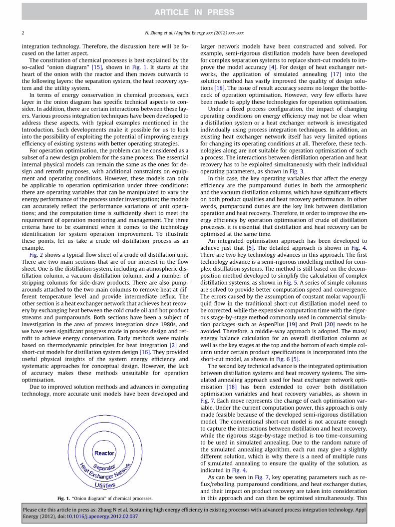
During the process of increasing CIT, column temperature dis-tribution and product quality were closely monitored. Betweenthe starting point and the finishing point, as shown in Figs. 12–16, there were very small changes in the temperature distributionof the atmospheric column and the distillation curves of all theatmospheric products. All changes in product quality were withinthe specification limits. Therefore, the energy saving was achievedwithout sacrificing the product quality.
y in existing processes with advanced process integration technology. Appl
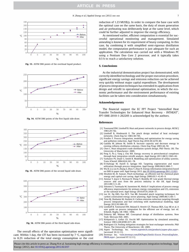
Fig. 13. ASTM D86 points of the overhead liquid product.
Fig. 14. ASTM D86 points of the first liquid side-draw.
Fig. 15. ASTM D86 points of the second liquid side-draw.
Fig. 16. ASTM D86 points of the third liquid side-draw.
N. Zhang et al. / Applied Energy xxx (2012) xxx–xxx 7
The overall effects of the operation optimisation were signifi-cant. Within 1 day, the CIT has been increased by 7 �C, equivalentto 8.2% reduction of the total energy consumption or the cost
Please cite this article in press as: Zhang N et al. Sustaining high energy efficiencEnergy (2012), doi:10.1016/j.apenergy.2012.02.037
reduction of 1.23 MUS$/y. In order to compare the base case withthe optimal case on the same basis, the duty of steam generationand air preheating was deliberately kept at the same level, whichcould be further adjusted to improve the energy efficiency.
As mentioned earlier, efficient computation is essential for suc-cessful operational monitoring and management. Simulatedannealing is known for its requirement of heavy computing. In thiscase, by combining it with simplified semi-rigorous distillationmodel, the computation performance is just adequate for such anapplication. The calculation was carried out with a Windows PCusing a Pentium Duo Core 2 processor, and it typically takes0.5 h to reach a satisfactory solution.
5. Conclusions
As the industrial demonstration project has demonstrated, withcorrectly identified technology and the proper execution procedure,significant energy savings and emission reduction can be achievedvery quickly without major capital expenditure. The developmentof process integration techniques has extended its applications fromdesign and retrofit to operational optimisation, in which the eco-nomic performance and the environment performance of existingfacilities can be taken into consideration simultaneously.
Acknowledgements
The financial support the EC FP7 Project ‘‘Intensified HeatTransfer Technologies for Enhanced Heat Recovery - INTHEAT’’,FP7-SME-2010-1-262205 is acknowledged by the authors.
References
[1] Townsend DW, Linnhoff B. Heat and power networks in process design. AIChE J1983;29:742.
[2] Linnhoff B, Hindmarsh E. The pinch design method of heat exchangernetworks. Chem Eng Sci 1983;38:745.
[3] Friedler F. Process integration, modelling and optimisation for energy savingand pollution reduction. Appl Therm Eng 2010;30:2270–80.
[4] Gadalla M, Jobson M, Smith R. Increase capacity and decrease energy inexisting refinery distillation columns. Chem Eng Progr 2003:44–50.
[5] Chen L. Heat integrated crude distillation system design, PhD Thesis. UK: TheUniversity of Manchester; 2009.
[6] Feng X, Pu J, Yang J, Chu KH. Energy recovery in petrochemical complexesthrough heat integration retrofit analysis. Appl Energy 2011;88(5):1965–82.
[7] Varbanov PS, Doyle S, Smith R. Modelling and optimisation of utility systems.Trans IChemE 2004;82A:561–78.
[8] El-Halwagi M, Harell D, Spriggs HD. Targeting cogeneration and wasteutilization through process integration. Appl Energy 2009;86(6):880–7.
[9] Wu B, Li J, Liu H, Zhang Z, Zhou Y, Zhao N. Energy information integration basedon EMS in paper mill. Appl Energy 2012. doi:10.1016/j.apenergy.2011.12.021.
[10] Ebrahim M, Al- Kawari. Pinch technology: an efficient tool for chemical-plantenergy and capital-cost saving. Appl Energy 2000;65(1–4):45–9.
[11] Ammar Y, Joyce S, Norman R, Wang Y, Roskilly AP. Low grade thermal energysources and uses from the process industry in the UK. Appl Energy2012;89(1):3–20.
[12] Siitonen S, Tuomaala M, Suominen M, Ahtila P. Implications of process energyefficiency improvements for primary energy consumption and CO2 emissionsat the national level. Appl Energy 2010;87(9):2928–37.
[13] Lee SC, Ng DKS, Foo DCY, Tan RR. Extended pinch targeting techniques forcarbon-constrained energy sector planning. Appl Energy 2009;86(1):60–7.
[14] Tiew BJ, Shuhaimi M, Hashim H. Carbon emission reduction targeting throughprocess integration and fuel switching with mathematical modeling. ApplEnergy 2012;92:686–93.
[15] Linnhoff B, Townsend DW, Boland D, Hewitt GF, Thomas BEA, Guy AR et al. Auser guide on process integration for the efficient use of energy. last ed.IChemE, Rugby, UK 1982; 1994.
[16] Doherty MF, Malone MF. Conceptual design of distillation systems. NewYork: McGraw-Hill; 2001.
[17] Kirkpatrick S, Gellat CD, Vecchi MP. Optimisation by simulated annealing.Science 1983;220(4598):671–80.
[18] Rodriguez CA. Fouling mitigation strategies for heat exchanger networks. PhDThesis, The University of Manchester, UK; 2005.
[19] Aspen Technology, Inc. <www.aspentech.com/products/aspen-plus.aspx>.[accessed 10.12.11].
[20] Invensys Inc. <iom.invensys.com/EN/Pages/SimSci-Esscor_ProcessEngSuite_PROII.aspx>. [accessed 07.12.11].
y in existing processes with advanced process integration technology. Appl