suunto octopus iins.suunto.com/.../usermanuals/favor_lux_s_octopusii_manual_en.pdf · 6 table of...
TRANSCRIPT

2
3
COPYRIGHT, TRADEMARK AND PATENT NOTICEThis instruction manual is copyrighted and all rights are reserved. It may not, in whole or in part, be copied, photocopied,reproduced, translated, or reduced to any media without prior written consent from SUUNTO.
SUUNTO, FAVOR, FAVOR LUX, FAVOR LUX S, FUSION, FUSION LUX S, OCTOPUS and their logos are all registered orunregistered trademarks of SUUNTO. All rights are reserved.
CEThe CE mark is used to mark conformity with the European Union EMC directive 89/336/EEC. The SUUNTO dive instrumentsfulfill all the required EU directives.
ISO 9001SUUNTO Oyj's Quality Assurance System is certified by Det Norske Veritas to be according to the ISO 9001 in all SUUNTOOyj's operations (Quality Certificate No. 96-HEL-AQ-220).
SUUNTO Oyj does not assume any responsibility for losses or claims by third parties, which may arise through the use of thisdevice.
Due to continuous product development the dive computer is subject to change without notice.
This instruction manual applies to FAVOR/LUX/LUX S, FUSION/LUX S and OCTOPUS II dive computers. Extra featuresand differences in operation are noted separately.PLEASE NOTE: In some countries FAVOR LUX S dive computer is called FUSION or FUSION LUX S.

4
DEFINITION OF WARNINGS, CAUTIONS AND NOTESThroughout this manual, special references are made when deemed important. Three classifications are used to separate thesereferences by their order of importance.WARNING - is used in connection with a procedure or situation that may result in serious injury or death.CAUTION - is used in connection with a procedure or situation that will result in damage to the product.NOTE - is used to emphasize important information.
WARNING!READ THIS MANUAL! Carefully read this instruction manual in its entirety, including Section 1, “For Your Safety”. Make surethat you fully understand the use, displays and limitations of this dive computer. Any confusion resulting from improper use ofthis device may cause diver to commit errors that may lead to serious injury or death.
WARNING!ONLY DIVERS TRAINED IN THE PROPER USE OF SCUBA EQUIPMENT SHOULD USE THIS DIVE COMPUTER! No divecomputer can replace the need for proper dive training. Insufficient or improper training may cause diver to commit errors thatmay lead to serious injury or death.
WARNING!PERFORM PRECHECKS! Always check this instrument before diving in order to ensure that all LCD segments are com-pletely displayed, that the dive computer has not run out of battery power, and that the personal and altitude adjustmentmode is correct.

5
WARNING!USE BACK-UP INSTRUMENTS! Make certain that you use back-up instrumentation including a depth gauge, submersiblepressure gauge, timer or watch, and have access to decompression tables whenever diving with this instrument.
WARNING!NO DIVE COMPUTER WILL PREVENT THE POSSIBILITY OF DECOMPRESSION SICKNESS (DCS)! All divers mustunderstand and accept that there is no procedure or dive computer that will totally prevent the possibility of a decompres-sion accident. For example, the individual physiological make up can vary within an individual from day to day. The divecomputer cannot account for these variations. As an added measure of safety, you should consult a physician regardingyour fitness before diving. Decompression sickness can cause serious injury or death.
WARNING!NOT FOR PROFESSIONAL USE! SUUNTO dive computers are intended for recreational use only. The demands of commer-cial or professional diving often expose the diver to depths and prolonged exposures including multiday exposures thattend to increase the risk of decompression sickness. Therefore, Suunto specifically recommends that this instrument is notused for commercial or other severe diving activity.

6
TABLE OF CONTENTS
QUICK REFERENCE GUIDE ...................................................................................................... 2
INTRODUCTION .......................................................................................................................... 8
1. FOR YOUR SAFETY ................................................................................................................ 10
2. GETTING ACQUAINTED WITH THE INSTRUMENT ........................................................ 172.1 WATER CONTACTS ....................................................................................................................................... 172.2 ACTIVATION ................................................................................................................................................... 18
3. DIVING WITH THE DIVE COMPUTER ............................................................................... 193.1 USE OF WATER CONTACTS ........................................................................................................................ 193.2 LUX/LUX S MODELS: TAP SWITCH AND ELECTROLUMINESCENT BACKLIGHT ...................... 213.3 BEFORE DIVING ............................................................................................................................................ 22
3.3.1 Activation, Prechecks and Battery Warning .............................................................................................. 223.3.2 Dive Planning ............................................................................................................................................ 253.3.3 Calendar Clock Function........................................................................................................................... 26
3.4 DIVING ............................................................................................................................................................ 273.4.1 Basic Dive Data ......................................................................................................................................... 273.4.2 Reverse No-Decompression Time Bar Graph ........................................................................................... 283.4.3 Ascent Rate Indicator ................................................................................................................................ 293.4.4 Alarms ....................................................................................................................................................... 313.4.5 Decompression Dives ................................................................................................................................ 32

7
3.5 AT SURFACE ................................................................................................................................................... 363.5.1 Surface Interval ......................................................................................................................................... 363.5.2 Flying After Diving ................................................................................................................................... 38
3.6 PERSONAL ADJUSTMENT AND HIGH ALTITUDE DIVES ................................................................... 393.7 ERROR CONDITIONS ................................................................................................................................... 41
4. MENU BASED MODES ........................................................................................................... 434.1 LOGBOOK MEMORY .................................................................................................................................... 444.2 DIVE HISTORY MEMORY ............................................................................................................................ 474.3 PERSONAL/ALTITUDE ADJUSTMENT SETTING................................................................................... 484.4 SETTING TIME AND DATE .......................................................................................................................... 50
5. CARE AND MAINTENANCE ................................................................................................. 525.1 MAINTENANCE ............................................................................................................................................. 535.2 BATTERY COMPARTMENT INSPECTION ................................................................................................ 54
6. TECHNICAL DESCRIPTION ................................................................................................ 556.1 OPERATING PRINCIPLES ............................................................................................................................ 556.2 TECHNICAL SPECIFICATION ..................................................................................................................... 61
7. WARRANTY ............................................................................................................................. 63
8. GLOSSARY ............................................................................................................................... 64

8
INTRODUCTION
Congratulations on your choice of the SUUNTO Dive Computer.
It is a compact and sophisticated dive instrument that will give you years of trouble free and joyful diving. The dive computerwill provide you with important information that you will need during, between, and after your dives.
KEY FEATURES
The dive computer monitors and reports vital information such as your dive time, current depth, maximum depth, no-decom-pression time and ascent rate.
The dive computer will also give you information, if through carelessness or emergency you are forced to exceed the no-decompression limits for any dive.
The instrument has a built-in calendar and clock. It features versatile logbook memory capabilities and long-term historicaldata. The instrument can be adjusted for diving at different altitudes or to add an extra level of conservativeness if desired.
The screen is protected against scratches and damage by a replaceable shield.
The dive computer is available either as a wrist unit with an optional protective boot or mounted in two gauge or three gaugeconsole or in a hose mounted boot. The modular construction allows for the separate compass module to be attached to thetwo gauge console at a later stage.

9
METRIC AND IMPERIAL UNITS
All examples in this manual are shown in metric units, including meters and °C. The corresponding imperial units are shown inbrackets. The instrument is also available with imperial units, i.e. feet and °F.
WARNING!VERIFY THAT THE UNITS OF MEASURE, WHETHER METRIC OR IMPERIAL, ARE CORRECT BEFORE STARTING TODIVE! Any confusion resulting from improper selection of units may cause the diver to commit errors that may lead toserious injury.

10
1. FOR YOUR SAFETYAlways remember that THE DIVER IS RESPONSIBLE FOR HIS OR HER OWN SAFETY!
When used properly this dive computer is an outstanding tool for assisting properly trained, certified divers in planning and executingstandard and multi-level sport dives within the described no-decompression limits. It is NOT A SUBSTITUTE FOR CERTIFIEDSCUBA INSTRUCTION including training in the principles of decompression.
DO NOT attempt to use this dive computer without reading this entire Instruction Manual. If you have any questions about themanual or the instrument itself, contact your Suunto dealer before diving with the dive computer.
BACK-UP INSTRUMENTS
WARNING!USE BACK-UP INSTRUMENTS! Make certain that you use back-up instrumentation including a depth gauge, submersiblepressure gauge, timer or watch, and have access to decompression tables whenever diving with this dive computer.

11
SHARING THE DIVE COMPUTER
WARNING!THE DIVE COMPUTER SHOULD NEVER BE TRADED OR SHARED BETWEEN USERS WHILE IT IS IN OPERATION! Itsinformation will not apply to someone who has not been wearing it throughout a dive or sequence of repetitive dives. Itsdive profiles must match that of the user. If it is left on the surface during any dive, it will give inaccurate information forsubsequent dives.
No dive computer can take into account dives made without the computer. Thus any diving activity 48 hours prior to initial useof the computer may give misleading information and must be avoided.

12
PERSONAL/HIGH ALTITUDE ADJUSTMENT
More information about this is given in Section 3.6, “Personal Adjustment and High Altitude Dives”.
WARNING!SET THE CORRECT PERSONAL/ALTITUDE ADJUSTMENT MODE! When diving at altitudes greater than 700 m [2300 ft]the personal/altitude adjustment feature must be correctly selected in order for the computer to calculate no-decompressionstatus. The diver should also use this option to make the calculation more conservative, whenever it is believed that factors whichtend to increase the possibility of decompression sickness exist (see Section 3.6). Failure to properly select the personal/altitudeadjustment mode correctly will result in er roneous data and can greatly increase the risk of decompression sickness.
WARNING!THE INSTRUMENT IS NOT INTENDED FOR USE AT ALTITUDES GREATER THAN 2400 m [8000 ft]! Diving at altitudesabove this limit may significantly increase the risk of decompression sickness.
When diving at higher altitudes (above 700 m / 2300 ft), it is essential that the entered altitude mode, i.e. maximum altitude limitof the dive computer, exceeds or is equal to the altitude of the dive site. The altitude mode indicator must show either A1 or A2,depending on the altitude. More information about this is given in Section 3.6, “Personal Adjustment and High Altitude Dives”.

13
DECOMPRESSION DIVES
WARNING!DO NOT USE THIS INSTRUMENT TO CONDUCT DECOMPRESSION DIVES! Suunto does not recommend this instru-ment to be used to conduct decompression dives. However, if through carelessness or emergency a diver is forced to exceedthe no-decompression limits on a dive, the instrument will provide decompression information required for ascent. After thisthe dive computer will continue to provide subsequent interval and repetitive dive information.
EMERGENCY ASCENTS
In the unlikely event that the instrument malfunctions during a dive, follow the emergency procedures provided by yourcertified dive training agency or, alternatively, immediately ascend at a rate slower than 10 m/min [33 ft/min] to a depth between3 and 6 meters [10 to 20 ft] and stay there as long as your air supply will safely allow.

14
HIGHER RISK DIVE PROFILES
The user must understand that all decompression devices (decompression tables and/or dive computers) are based onmathematical models and that many experts are currently concerned that these models may not under certain conditionsadequately describe the physiological phenomena. These conditions are presently identified as dives which incorporate thefollowing (Fig. 1.1):
• SAWTOOTH PROFILES where the diver alternates between greater and shallower depths repeatedlythroughout the dive.
• REVERSE PROFILES where the diver spends most of the dive at shallow depths and then descendsto the maximum depth shortly before surfacing.
• CONSECUTIVE DIVES where the diver performs repetitive dives to approximately the same maximumdepth with only short surface intervals between dives. The risk of decompression sickness increases when depth and the number of repetitive divesincrease and when the surface intervals are decreased.
• MULTIDAY DIVES repetitive dives performed for several consecutive days.
• DECOMPRESSION DIVES any dive during which the no-decompression limit has been exceeded or thediver is advised by the computer that he may not return directly to the surface.

15
WARNING!DIVE PRACTICES WHICH INCLUDE THE ABOVE DESCRIBED “HIGHER RISK DIVE PROFILES” ARE BELIEVED TOINCREASE THE RISK OF DECOMPRESSION SICKNESS AND AS SUCH CONSIDERED POTENTIALLY DANGEROUSAND SHOULD BE AVOIDED EVEN IF THEY CONFORM TO THE MATHEMATICAL MODEL!
WARNING!DO NOT USE THE DIVE COMPUTER WITH NITROX MIX! The mathematical tissue calculation model of the instrumenthas been designed for use with standard breathing air only (approximately 21% oxygen and 79% nitrogen by volume).Therefore, the dive computer must not be used for diving with “Nitrox” or other mixed gases.
Fig. 1.1 HIGHER RISK DIVE PROFILES Fig. 1.2 RECOMMENDED PROFILE
time
dept
h
Consecutive dives
Multiday dives
time
dept
h
Reverse profiles
time
dept
h
Sawtooth profiles
time
dep
th
16
DIVE COMPUTER LIMITATIONS
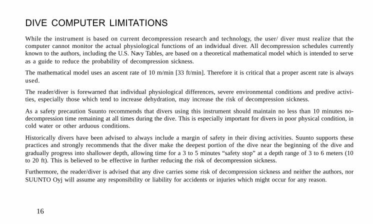
While the instrument is based on current decompression research and technology, the user/ diver must realize that thecomputer cannot monitor the actual physiological functions of an individual diver. All decompression schedules currentlyknown to the authors, including the U.S. Navy Tables, are based on a theoretical mathematical model which is intended to serveas a guide to reduce the probability of decompression sickness.
The mathematical model uses an ascent rate of 10 m/min [33 ft/min]. Therefore it is critical that a proper ascent rate is alwaysused.
The reader/diver is forewarned that individual physiological differences, severe environmental conditions and predive activi-ties, especially those which tend to increase dehydration, may increase the risk of decompression sickness.
As a safety precaution Suunto recommends that divers using this instrument should maintain no less than 10 minutes no-decompression time remaining at all times during the dive. This is especially important for divers in poor physical condition, incold water or other arduous conditions.
Historically divers have been advised to always include a margin of safety in their diving activities. Suunto supports thesepractices and strongly recommends that the diver make the deepest portion of the dive near the beginning of the dive andgradually progress into shallower depth, allowing time for a 3 to 5 minutes “safety stop” at a depth range of 3 to 6 meters (10to 20 ft). This is believed to be effective in further reducing the risk of decompression sickness.
Furthermore, the reader/diver is advised that any dive carries some risk of decompression sickness and neither the authors, norSUUNTO Oyj will assume any responsibility or liability for accidents or injuries which might occur for any reason.

17
2. GETTING ACQUAINTED WITH THE DIVE COMPUTER
WARNING!READ AND UNDERSTAND THE ENTIRE OWNER’S MANUAL BEFORE DIVING! Failure to complete this step may resultin serious personal injury.
The purpose of this section is to provide the user with initial information to preview the operation of the computer. Since thisinformation is limited, it is imperative that you read and understand the entire owner’s manual before attempting to dive.
2.1 WATER CONTACTS The dive computer has three water contacts on the face of the instrument:
• COM: common contact
• PLAN/ON: activation and dive planning contact
• TIME/MODE: time display and mode selection contact
On the surface the instrument is operated by simultaneously touching the COM contact and one or two of the other contacts.When doing this, your finger tips should be wet or moist to establish the necessary electric contact. When submerged thesecontacts are automatically connected by the conductivity of the water.

18ALT SET PLAN
C
ME
DIVETIME
2.2 ACTIVATIONThe calendar clock is always shown on the display, when the dive computer is deacti-vated. In this mode the power consumption is minimal.
The instrument is activated by touching the PLAN/ON and COM contacts (Fig 2.1).The f irst display, the STARTUP, shows all available elements and immediately after thisthe battery power indicator. A few seconds later the READY display will appear, show-ing zero values (Fig. 2.2).
At this time, perform a precheck making sure that the dive computer operates correctly,that the low battery indicator is not on and that the personal/altitude adjustmentsetting is correct.
If the battery symbol is displayed the dive computer should not be used (Fig. 2.3).
Fig. 2.1 ACTIVATIONTouch the PLAN/ON and COM contactswith moistened fingers.
Fig. 2.3 BATTERY WARNINGThe battery symbol indicates that the batteryis too low for diving.
Fig. 2.2 READY DISPLAY
COM
TIMEMODE
PLANON
LOG HIS ALT SET PLAN
ASCRATE
m
NO DEC TIMEDIVE
C F
SURF TIMEA2A1A0
NOCEILING ASC TIME
MAX
MAX
DIVETIME
LOG HIS ALT SET PLAN
ASCRATE
m
C
SURF TIME
A1
DIVETIME
MAX

19
3. DIVING WITH THE DIVE COMPUTERThis section contains instructions on how to operate the dive computer and interpretits displays. Each display has been carefully designed to provide important informationyou will need to plan your dive or dive series.
You will find that the ínstrument is easy to use and read. Each display shows only the datarelevant to that specific diving situation. For example, while you are on a dive, surfaceinterval data is irrelevant and therefore not shown. On the other hand, while you are on thesurface after a dive, remaining no-decompression time for that dive is irrelevant and thereforereplaced with information for your next dive.
3.1 USE OF WATER CONTACTSAs described in Section 2.1, “Water Contacts”, the dive computer is controlled with theCOM (common), PLAN/ON, and TIME/MODE contacts (Fig 3.1), as follows:
Activation: touch the PLAN/ON and COM contacts.
Dive planning: once the instrument has been activated, touchthe PLAN/ON and COM contacts.
Clock: once the instrument has been activated, touch theTIME/MODE and COM contacts for two seconds.The time is then displayed for four seconds.
Fig. 3.1 USING THE WATERCONTACTSa) Activation and dive planningb) Time display and menu based modesc) Exit the modes
COM
TIMEMODE
PLANON
LOG HIS ALT SET PLAN
ASCRATE
m
COM
TIMEMODE
PLANON
LOG HIS ALT SET PLAN
ASCRATE
m
COM
TIMEMODE
PLANON
LOG HIS ALT SET PLAN
ASCRATE
m

20
When the TIME/MODE and COM contacts are touched for over three seconds, the display will start to scroll through the followingmodes. Lift your fingers when the desired mode is displayed:
Logbook memory: at LOG the logbook memory is accessed.
Dive history memory: at HIS the history memory is accessed.
Personal/altitude adjustment setting: at Alt the personal and/or altitude adjustment can be set.
Time setting: at Set the time and date can be adjusted.
Return: you can at any time exit the above modes by touching all three contacts at thesame time. First make contact between the PLAN/ON and TIME/MODEcontacts, e.g. by covering both contacts with your right thumb. Withoutlifting your right thumb, touch the COM contact with your left thumb.Alternatively, you can exit the modes simply by submerging the dive computerin water.
You may sometimes encounter problems in using the contacts, or the instrument may activate on its own. The reason for thisis probably contamination or invisible marine growth that may create an unwanted electric current between the water contacts.It is therefore important that the dive computer be carefully washed in fresh water after the day’s diving is completed. Thecontacts can be cleaned with a soft pencil eraser.

21
3.2 LUX/LUX S MODELS: TAP SWITCH ANDELECTROLUMINESCENT BACKLIGHTThe tap switch is used to activate the electroluminescent backlight. The switch is usedby pressing or tapping the movement sensitive area with your finger. This area is on theface of the instrument between the ON/PLAN and TIME/MODE water contacts markedwith a “¤ LUX” symbol.
The light can be activated in all modes when the computer is on. The illumination goesoff automatically after approximately 10 seconds from activation. With a little practicingyou will quickly figure out how to use the tap switch. Do the practicing in a dark roomso you can see when the light goes on.
NOTE: For safety reasons the lamp will not come on, if the battery voltage is low (thelow battery symbol is displayed).
Fig. 3.2 ACTIVATING THEBACKLIGHTPress or tap the movement sensitive areamarked with a “¤ LUX” symbol.
COM
TIMEMODE
PLANON
LOG HIS ALT SET PLAN
ASCRATE
m

22
3.3 BEFORE DIVING
3.3.1 Activation, Prechecks and Battery WarningThe instrument is always ready for use and will activate if submerged. However, it isnecessary to turn it on before diving to check the personal/ altitude adjustment setting,battery power, etc. This is done, either by immersing it in water for a couple of secondsor by connecting the PLAN/ON and COM contacts with fingertips.
When deactivated the time display is always shown. Once activated all display ele-ments will turn on (showing mostly figure 8’s and graphical elements) (Fig. 3.3). A fewseconds later the battery power bar graph is shown (Fig. 3.4). Next, the screen willalternate between two READY displays, confirming that the activation is complete (Fig.3.5). At this time, perform your precheck making sure that:
• the dive computer operates and provides a complete display
• the low battery indicator is not on
• the personal/ altitude adjustment setting is correct
The instrument is now ready for diving. If it is not taken on a dive after activation, it willautomatically switch off to the time display in 10 minutes to conserve the battery power.
The dive computer does not need to be reactivated for repetitive dives. It will remain activeuntil it has calculated that all residual nitrogen has off-gassed. This may take up to 48 hours,as described in Section 6.1, “Operating Principles”.
Fig. 3.3 STARTUP IAll segments shown.
Fig. 3.4 STARTUP IIBattery power indicator. When two or less bargraph segments are shown the computer shouldnot be used for diving. (First generation LUX/LUX S computers: When four or less bargraph segments are shown the computer shouldnot be used for diving. For further informationsee NOTE on page 24.)
LOG HIS ALT SET PLAN
ASCRATE
m
NO DEC TIMEDIVE
C F
SURF TIMEA2A1A0
NOCEILING ASC TIME
MAX
MAX
DIVETIME
c
a
b
d
eLOG HIS ALT SET PLAN
ASCRATE
m
LOG HIS ALT SET PLAN
ASCRATE
m
LOG HIS ALT SET PLAN
ASCRATE
m
LOG HIS ALT SET PLAN
ASCRATE
m
NOLOG HIS ALT SET PLAN
ASCRATE
m
23
PERSONAL ADJUSTMENT AND HIGH ALTITUDEDIVING
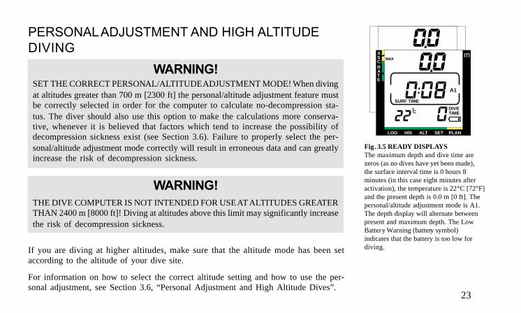
WARNING!SET THE CORRECT PERSONAL/ALTITUDE ADJUSTMENT MODE! When divingat altitudes greater than 700 m [2300 ft] the personal/altitude adjustment feature mustbe correctly selected in order for the computer to calculate no-decompression sta-tus. The diver should also use this option to make the calculations more conserva-tive, whenever it is believed that factors which tend to increase the possibility ofdecompression sickness exist (see Section 3.6). Failure to properly select the per-sonal/altitude adjustment mode correctly will result in erroneous data and can greatlyincrease the risk of decompression sickness.
WARNING!THE DIVE COMPUTER IS NOT INTENDED FOR USE AT ALTITUDES GREATERTHAN 2400 m [8000 ft]! Diving at altitudes above this limit may significantly increasethe risk of decompression sickness.
If you are diving at higher altitudes, make sure that the altitude mode has been setaccording to the altitude of your dive site.
For information on how to select the correct altitude setting and how to use the per-sonal adjustment, see Section 3.6, “Personal Adjustment and High Altitude Dives”.
Fig. 3.5 READY DISPLAYSThe maximum depth and dive time arezeros (as no dives have yet been made),the surface interval time is 0 hours 8minutes (in this case eight minutes afteractivation), the temperature is 22°C [72°F]and the present depth is 0.0 m [0 ft]. Thepersonal/altitude adjustment mode is A1.The depth display will alternate betweenpresent and maximum depth. The LowBattery Warning (battery symbol)indicates that the battery is too low fordiving.
LOG HIS ALT SET PLAN
ASCRATE
m
C
SURF TIME
A1
DIVETIME
MAX

24
TABLE 3.1 BATTERY POWER INDICATOR
BATTERY POWER INDICATOR AND LOW BATTERY WARNING
The instrument has a unique visual Battery Power Indicator designed to give you an advance notice of impending need tochange the battery.
The Battery Power Indicator will always be seen during activation. The following table 3.1 shows the various warning levels(see also Fig. 3.4).
*) NOTE: First generation LUX/LUX S models made before March 1999 (serial number less than 909001 [first number standsfor year, next two numbers stand for week, last three numbers stand for production number]): Resulting from different batterycontrol system, when four or less bar graph segments are shown the computer should not be used for diving. Battery change isrecommended.
Display after activation Operation*) Figure
five (5) bar graph segments normal, new battery 3.4 a)and
four (4) bar graph segments 3.4 b)
three (3) bar graph segments battery change is recommended 3.4 c)
two (2) bar graph segments don't dive, change the battery 3.4 d)
one (1) bar graph segment don't dive, after three activations the computerremains deactivated until the battery has beenreplaced
3.4 e)

25
After activation the Low Battery Warning is indicated by the battery symbol. If thebattery symbol is displayed in the surface mode or if the display is faded or weak, thedive computer should not be used (Fig. 3.5). It indicates that the battery is too low tooperate the instrument. If the low battery symbol appears during a dive, you shouldabort the dive and begin ascent to the surface.
NOTE: The backlight of the LUX/LUX S models can not be activated, when the lowbattery warning is indicated by the battery symbol.
NOTE: Temperature affects the battery voltage. If the dive computer is stored attemperatures below freezing point, the low battery warning may be displayed eventhough the battery has enough capacity in warmer conditions. Make sure that the lowbattery warning disappears before diving.
3.3.2 Dive PlanningIt is possible at any time on the surface to enter the DIVE PLANNING mode, simply bytouching the PLAN/ON and COM contacts. The display will rapidly cycle through theno-decompression limits for various depths from 9 m [30 ft] to 45 m [150 ft] in 3 m [10 ft]increments (Fig. 3.6). It takes about 45 seconds to run through the complete cycle, afterwhich the dive computer will automatically return to the READY display.
Higher personal/ altitude adjustment modes will shorten the no-decompression timelimits. These limits at different personal/ altitude adjustment mode selections are shownin Tables 6.1 and 6.2 in Section 6.1, “OPERATING PRINCIPLES”.
Fig. 3.6 DIVE PLANNINGThe no-decompression time limit at 30.0 m[100 ft] is 14 minutes in A1 mode.
LOG HIS ALT SET PLAN
ASCRATE
m
NO DEC TIMEDIVE
A1
DIVETIME

26
DIVE NUMBERING SHOWN DURING DIVEPLANNING
Several repetitive dives are considered to belong to the same repetitive dive serieswhen the dive computer has not deactivated itself. The first dive of the series will benumbered as DIVE 1, the second as DIVE 2, the third as DIVE 3 etc. (Fig. 3.7). When thesurface time has been less than 10 minutes, the dives are considered to be the same. Thedive number will not change for the second part of such a dive and the dive time willstart where it left off.
3.3.3 Calendar Clock FunctionThe calendar clock is always shown on the display, when the instrument is deactivated.
Once the dive computer is activated the TIME display can be retrieved any time on thesurface mode by touching the TIME/MODE and COM contacts for about two seconds.The current time and date will be shown for four seconds (Fig. 3.8).
When diving, the dive entry time and date is registered in the logbook memory. Remem-ber always to check before diving that the clock is set, especially when traveling todifferent time zones. For adjusting the clock, refer to Sec. 4.4, “Setting Time and Date”.
In the metric version of the instrument, the 24-hour time system is used, while in theimperial version the 12-hour time system is used.
Fig. 3.7 DIVE PLANNINGThe no-decompression time limit at 30.0 m[100 ft] is decreased to 5 minutes in A1 modeafter the third dive of the series.
Fig. 3.8 TIME DISPLAYThe time is 10:30 [in case of imperial unit, Afor a.m. and P for p.m. would be shown in theupper left corner of the display]. The date is18.2 or February 18th. PLEASE NOTE: Thedate will always be displayed with the day ofthe month first, followed by the month.
LOG HIS ALT SET PLAN
ASCRATE
m
NO DEC TIMEDIVE
A1
DIVETIME
LOG HIS ALT SET PLAN
ASCRATE
m

27
3.4 DIVING
3.4.1 Basic Dive Data
The dive computer will remain in the SURFACE mode at depths less than 1.2 m [4 ft](first generation computers 1.8 m [6 ft]). At depths greater than 1.2 m (1.8 m first generationcomputers) the instrument will go into the DIVE mode.
Each piece of information on the display is clearly marked (Fig. 3.9). During a no-decompression dive, the following information will be shown:
• the available no-decompression time (a) in minutes is shown as NO DECTIME. It is calculated based on the five factors listed in Section 6.1, “OPERAT-ING PRINCIPLES”.
• your present depth (d) is shown in meters [ft].
• the elapsed dive time (f) in minutes in the lower right corner, shown as DIVETIME.
• the personal/ altitude adjustment (e) setting (A0, A1, or A2).
In the lower left corner the following information will alternate:
• the maximum depth during this dive (b) in meters [ft], indicated as MAX,for about 5 seconds.
• the water temperature (c), with °C for Centigrade [or °F for Fahrenheit], for
about 3 second.
Fig. 3.9 DIVING DISPLAYThe present depth is 19.3 m [63 ft] (d), theno-decompression time limit is 23 minutes(a) in A1 mode (e) and the dive time is 6minutes (f). Maximum depth during thisdive 29.8 m [98 ft] (b) and watertemperature 18°C [64°F] (c) are alternatingin the lower left corner.
ASCRATE
LOG HIS ALT SET PLAN
ASCRATE
m
CDIVETIMEc
a
LOG HIS ALT SET PLAN
ASCRATE
NO DEC TIME
A1
DIVETIME
MAX
m
a
b
d
e
f

28
3.4.2 Reverse No-Decompression Time Bar GraphThe available no-decompression time is also shown visually in the multi-function bargraph in the bottom of the display (Fig. 3.10). When your available no-decompressiontime decreases below 60 minutes, the first bar graph segment appears. As your bodyabsorbs more nitrogen, more segments start to appear.
Green Zone (a)As a safety precaution Suunto recommends that divers using the dive computer shouldmaintain the no-decompression bar graph within the green zone.
Yellow Zone (b)As all of the bars appear (yellow zone), your no-decompression limit is less than 10minutes and you are getting very close to no-decompression limits. At this point, youshould start your ascent towards the surface.
Fig. 3.10 REVERSE NO-DECOMPRESSION TIME BAR GRAPHThe first bar from the left appears, when theavailable no-decompression time decreasesbelow 60 minutes. The following barsappear, when the available no-decompressiontime decreases below 40, 30, 20 (green zone,a) and 10 minutes (yellow zone, b).
Fig. 3.11 ASCENT RATE INDICATORPointer at position two: ascent rate 7 - 9 m/min [23 - 30 ft/min].
ASCRATE
LOG HIS ALT SET PLAN
ASCRATE
NO DEC TIME
A1
DIVETIME
MAX
m
a b
LOG HIS ALT SET PLAN
ASCRATE
NO DEC TIME
A1
DIVETIME
MAX
m

29
3.4.3 Ascent Rate IndicatorThe ascent rate is shown graphically with a pointer in the upper left corner, next to thenotation ASC RATE, as follows:
Fig. 3.12 ASCENT RATE INDICATORPointer at position three: ascent rate 9 - 11m/min [30 - 36 ft/min].
Fig. 3.13 ASCENT RATE INDICATORPointer at position four: ascent rate is morethan 11 m/min [36 ft/min]. BlinkingSLOW displayed means that the ascentrate 10 m/min [33 ft/min] has beenviolated continuously. This is a caution toslow down!
LOG HIS ALT SET PLAN
ASCRATE
NO DEC TIME
A1
DIVETIME
mMAX
C
LOG HIS ALT SET PLAN
ASCRATE
NO DEC TIME
A1
DIVETIME
MAX
m
Ascent rate indicator Ascent speed Example in Fig. no.
No segmentsBelow 5 m/min[16 ft/min]
3.9
Segment one5 - 7 m/min[16 - 23 ft/min] 3.10
Segment two 7 - 9 m/min[23 - 30 ft/min]
3.11
Segment three 9 - 11 m/min[30 - 36 ft/min]
3.12
Segment fourAbove 11 m/min[36 ft/min]
3.13
Blinking SLOWAbove 10 m/min[33 ft/min]
3.13

30
The SLOW warning alternates with the current depth. The SLOW warning is an indication that the maximum ascent rate hasbeen exceeded continuously, whereas the ascent rate indicator shows present ascent speed.
Whenever the SLOW warning appears, you should immediately slow down or stop your ascent until the warning disappears.You must not ascend shallower than 3 m [10 ft] with the SLOW warning on. If you reach this depth with SLOW on, you muststop at this depth and wait until the warning disappears.
WARNING!RAPID ASCENTS INCREASE THE RISK OF INJURY! Do not exceed the maximum recommended ascent rate.
You must never surface with the SLOW warning on. If you do this, the warning will continue to flash until the unit deactivatesitself in the normal manner. This may take up to 40 hours.
WARNING!DO NOT ATTEMPT TO DIVE FOLLOWING A SURFACE INTERVAL DURING WHICH THE SLOW INDICATOR RE-MAINS ACTIVATED! Violation of the maximum ascent rate may invalidate the calculations for the next dive.
NOTE: SUUNTO highly recommends a safety stop at the end of every dive in the range of 3 m - 6 m [10 ft - 20 ft] for 3 - 5minutes.

31
3.4.4 AlarmsThe standard and LUX models feature visual alarms, and the LUX S visual as well as audible alarms, to alert you when you areapproaching dangerous situations.
Potential danger situations during a dive, occurs when:
• the no-decompression dive turns into a decompression dive. One arrow pointing upwards and the ascend warningCEILING/ASC TIME will appear (Fig. 3.14). LUX S model gives also an audible alarm: three single beeps.
Immediate danger, happens when:
• the maximum allowed ascent rate, 10 m/min [33 ft/min], is exceeded. A blinking SLOW warning will alternate withthe depth display (Fig. 3.13). LUX S model gives also an audible alarm; continuous beep.
• the ceiling depth is exceeded. A downward pointing ar row and a blinking error warning Er will appear (Fig.3.17).LUX S model gives also an audible alarm: continuous beep. You should immediately descend to or below theceiling. The dive computer will otherwise enter a permanent error mode in three minutes, indicated by anon-blinking Er.
• the ceiling descends to 10 m [30 ft]. A blinking error warning Er appears. You should immediately ascend to or
below the ceiling.
• the ceiling descends to 12 m [39 ft]. A permanent error warning Er appears. In this mode the instrument can only beused as a depth gauge and timer.
The permanent ERROR MODE is shown by a non-blinking Er in the center display. Once in ERROR MODE, the dive computer willcontinue to display current depth and dive time. You should immediately ascend to a depth of 3 to 6 m [10 to 20 ft] and remain at thisdepth until air supply limitations require you to surface. When the surface has been reached, no further diving or flying should take placefor a minimum of two days.

32
3.4.5 Decompression dives
WARNING!DO NOT USE THIS INSTRUMENT TO CONDUCT DECOMPRESSION DIVES!Suunto does not recommend this instrument to be used to conduct decompressiondives. However, if through carelessness or emergency a diver is forced to exceed theno-decompression limits on a dive, the dive computer will provide decompressioninformation required for ascent. After this the instrument will continue to providesubsequent interval and repetitive dive information.
Rather than requiring you to make stops at fixed depths, the dive computer permits youto decompress within a range of depths.
BACKGROUND
When your NO DEC TIME becomes zero, your dive becomes a decompression dive, i.e.you must perform one or several decompression stops on your way to the surface. TheNO DEC TIME on your display will be replaced by a flashing notation CEILING/ ASCTIME (Fig. 3.14).
WARNING!YOU SHOULD ASCEND AND BEGIN DECOMPRESSION IMMEDIATELY WHENTHE DIVE COMPUTER SHOWS YOU THAT DECOMPRESSION IS REQUIRED!Note the upward pointing arrow.
Fig. 3.14 DECOMPRESSION DIVE,BELOW THE CEILING ZONEThe minimum ascent time is 4 minutes. Theupward pointing arrow tells you to ascend.The ceiling is at 3 m [10 ft].
Fig. 3.15 DECOMPRESSION DIVE, ATTHE CEILING ZONEThe two arrows (a) point at each other ("hourglass"). You are at the ceiling zone at 3.5 m [11ft] (c) and your minimum ascent time is 3minutes (d). The ceiling is at 3 m [10 ft] (b).
LOG HIS ALT SET PLAN
ASCRATE
m
A1
CEILING ASC TIME
MAX DIVETIME
LOG HIS ALT SET PLAN
ASCRATE
m
A1
CEILING ASC TIME
MAX DIVETIME
a
b
c
d

33
The ascent time (ASC TIME) is the minimum amount of minutes needed to reach the surface in a decompression dive. Itincludes: The time needed to ascend to the ceiling at an ascent rate of 10 m/min [33 ft/min]plusThe time needed at the ceiling. The ceiling is the shallowest depth to which you should ascendplusThe time needed to reach the surface after the ceiling has been removed.
NOTE: Ascent time is not displayed in the Octopus II dive computer (see Figure 3.16).
WARNING!YOUR ACTUAL ASCENT TIME MAY BE LONGER THAN DISPLAYED ON THE DIVE COMPUTER.
The ascent time will increase if you:
• remain at depth
• ascend slower than 10 m/min [33 ft/min] or
• make your decompression stop deeper than at the ceiling.
These factors will also increase the amount of air required to reach the surface.
WARNING!NEVER ASCEND ABOVE THE CEILING! You must not ascend above the ceiling. In order to avoid doing so by accident,you should stay slightly below the ceiling. The ceiling zone is the shallowest depth range to which you should ascend whenin decompression.

34
DISPLAY BELOW CEILING ZONE
The CEILING/ASC TIME symbol and upwards pointing arrow indicate that you arebelow the ceiling zone (Fig. 3.14). You should start your ascent immediately.
DISPLAY AT CEILING ZONE
When you reach the ceiling zone, the display will show you two arrows pointing towardeach other (the “hour glass” icon, Fig. 3.15). The two ar rows pointing toward each otherwill be shown between the minimum ceiling and 1.8 m [6 ft] below the minimum ceiling.All decompression stops must be performed at or below the ceiling depth range.
The depth of the ceiling will depend on your dive prof ile. It will be fairly shallow whenyou enter the decompression mode, but if you remain at depth, it will move downwardand the ascent time will increase.
The ceiling depth will be shown on the left side of the center window.
When the sea surface is rough, it may be difficult to maintain a constant depth near thesurface. In this case it will be more manageable to maintain an additional distance belowto the ceiling, to make sure that the waves do not lift you above the ceiling. SUUNTOrecommends that decompression takes place deeper than 4 m [13 ft], even if the indi-cated ceiling is shallower.
NOTE: It will take more time and more air to decompress below the ceiling than at theceiling.
Fig 3.16 OCTOPUS II DECOMPRES-SIONDIVE, AT THE CEILING ZONEThe two arrows (a) point at each other ("hourglass"). You are at the ceiling zone at 3.5 m[11 ft] (c) and the ceiling is at 3 m [10 ft] (b).
Fig. 3.17 DECOMPRESSION DIVE,ABOVE CEILINGNote the downward pointing arrow and theblinking Er warning. You should immediately(within 3 minutes) descend to or below theceiling.
LOG HIS ALT SET PLAN
ASCRATE
m
A1b
c
dCEILING ASC TIME
MAX DIVETIME
a
LOG HIS ALT SET PLAN
ASCRATE
m
A1
CEILING ASC TIME
DIVETIMEC

35
DISPLAY ABOVE CEILING
If you ascend above the ceiling, a downward pointing arrow will appear (Fig 3.17). Inaddition a blinking error warning Er reminds you that you have only three minutes tocorrect the situation. You must immediately descend to or below the ceiling.
If you continue to violate the decompression requirements, the dive computer goesinto a permanent ERROR MODE. In this mode (Fig. 3.18) you must not dive again for atleast two days. See also Section 3.7, Error Conditions.
During decompression, ASC TIME will count down toward zero. When the ceilingmoves upwards, you can ascend to the new ceiling. You may surface only when theascent time reaches zero and CEILING/ASC TIME is replaced by NO DEC TIME.
WARNING !NEVER LET THE CEILING DEPTH DESCEND DEEPER THAN 9 m [30 ft]. When theceiling is deeper than 9 m [30 ft], a blinking error warning Er will appear and when the12 m [39 ft] ceiling is reached the dive computer will go into a permanent error mode.
Fig. 3.18 DISPLAYS AFTER VIOLATEDDECOMPRESSION DIVEThe blinking CEILING/ASC TIME symbol(a) indicates that you have violated the ceilingfor more than three minutes or the maximumceiling depth of 12 m [39 ft] was exceeded.The instrument will stay as a depth gauge andtimer for 39 hours 59 minutes = no fly time(b). After 2 hours 30 minutes surface intervaltime the no fly time is 37 hours 29 minutes.In the dive planning mode the Er warning isdisplayed instead of the no-decompressiontime (c). You must not dive again or fly for atleast two days.
LOG HIS ALT SET PLAN
ASCRATE
m
C
A1
NO
DIVETIME
LOG HIS ALT SET PLAN
ASCRATE
m
NO DEC TIMEDIVE
A1
DIVETIME
LOG HIS ALT SET PLAN
ASCRATE
m
C
SURF TIME
A1
NOCEILING ASC TIME
DIVETIME
MAX
b
a
c

36
3.5 AT SURFACE
3.5.1 Surface IntervalAn ascent to any depth shallower than 1.2 m [4 ft] (first generation computers 1.8 m [6ft]) will cause the DIVING display to be replaced by the two SURFACE displays, givingthe following information:
Display I (Fig. 3.19)• The surface time in hours and minutes (separated by a colon), telling the
duration of the present surface interval. It is shown above SURF TIME inthe center window of the display (Fig. 3.19, b).
• The dive time in minutes, i.e. the total duration of the most recent dive, isdisplayed next to DIVE TIME in the lower right corner (Fig. 3.19, f).
• The maximum depth of your most recent dive in meters [ft] is shown in the
same position as your depth readings during the dive. MAX indicator isthen shown in front of the value (Fig. 3.19, a). The SLOW warning will blinkover the maximum depth, if you have surfaced with the SLOW warning on(Fig. 3.19, d).
• The temperature in °C [°F] is shown in the lower left corner (Fig. 3.19, c).
• The no-flying warning is indicated by a blinking airplane (Fig. 3.19, e).
Fig. 3.19 SURFACE MODE AFTER ADIVE, DISPLAY IYou have surf aced with the SLOW warning on(d) 35 minutes ago (b) from a 46 minute dive(f) that reached a maximum depth of 29.8 m[98 ft] (a). The blinking airplane symbol (e)indicates that you should not fly. Thetemperature is 28°C [82°F] (c).
LOG HIS ALT SET PLAN
ASCRATE
m
C
SURF TIME
A1
NO
DIVETIME
MAXa
b
d
fc
e

37
Display II (Fig. 3.20)
• The present depth in meters [ft] (Fig. 3.20, a).
• The desaturation/ no-flying time in hours and minutes is shown next to thenon-blinking airplane in the center window of the display (Fig. 3.20, b).
If you start a new dive after less than 10 minutes at the surface, the instrument interpretsthis as a continuation of the previous dive. The DIVING display will return, the DIVEnumber will remain unchanged, and DIVE TIME will begin where it left off. After 10minutes on the surface, subsequent dives are by def inition repetitive. The DIVE counterdisplayed in the dive planning mode will progress to the next higher number if you makeanother dive after 10 minutes of surface interval time.
DIVE PLANNING
You may, at any time on the surface, enter the DIVE PLANNING mode in the mannerdescribed in Section 3.3.2, by touching the PLAN/ON and COM contacts. The divecomputer will take into account the residual nitrogen caused by your previous dives.The no-decompression times given for different depths will therefore be shorter thanbefore your first dive (Fig. 3.7).
You may also read the time by touching the TIME/MODE and COM contacts, as de-scribed in Section 3.3.3 (Fig. 3.8).
Fig. 3.20 SURFACE MODE AFTER ADIVE, DISPLAY IIThe desaturation time/ no-flying time,indicated by a non-blinking airplane symbol,is 11 h 25 min (b). The present depth is 0.0m [0 ft] (a).
LOG HIS ALT SET PLAN
ASCRATE
m
C
A1
NO
DIVETIME
a
b

38
3.5.2 Flying After DivingThe no-flying time is shown in the center window next to the non-blinking airplane image. The blinking airplane is a reminder,when the alternative display showing surface time is on (Figures 3.19 and 3.20). Flying or traveling to a higher altitude shouldbe avoided anytime the airplane symbol is displayed.
The no-flying time displayed by the dive computer is always at least 12 hours or equivalent to the so-called desaturation time(if longer than 12 hours). When this time has elapsed, the residual nitrogen is no longer a factor for subsequent dives. At thistime the instrument will automatically deactivate itself.
In the permanent ERROR mode the no-flying time displayed is 39 hours 59 minutes.
Flying or traveling to a higher altitude after a dive may significantly increase the risk of decompression sickness.
WARNING!YOU ARE ADVISED TO AVOID FLYING ANYTIME THE COMPUTER DISPLAYS THE DO NOT FLY WARNING - INDI-CATED BY AN AIRPLANE! Further, the Divers Alert Network (DAN) advises as follows:
• A minimum surface interval of 12 hours would be required in order to be reasonably assured a diver will remainsymptom free upon ascent to altitude in a commercial jetliner (altitude up to 2400 m [8000 ft]).
• Divers who plan to make daily, multiple dives for several days, or make dives that require decompression stops,should take special precautions and wait for an extended interval beyond 12 hours before flight.
Suunto recommends that flying be avoided until both the DAN guidelines and the dive computer wait to fly conditions aresatisfied.

39
3.6 PERSONAL ADJUSTMENT AND HIGH ALTITUDE DIVESThe instrument can be adjusted for increasing the conservatism of the mathematical model or for diving at altitude.
WARNING!SET THE CORRECT PERSONAL/ALTITUDE ADJUSTMENT MODE! When diving at altitudes greater than 700 m [2300 ft]the personal/altitude adjustment feature must be correctly selected in order for the computer to calculate no-decompressionstatus. The diver should also use this option to make the calculations more conservative, whenever it is believed thatfactors which tend to increase the possibility of decompression sickness exist. Failure to properly select the personal/altitude adjustment mode correctly will result in erroneous data and can greatly increase the risk of decompression sickness.
WARNING!THE DIVE COMPUTER IS NOT INTENDED FOR USE AT ALTITUDES GREATER THAN 2400 m [8000 ft]! Traveling to ahigher elevation can temporarily cause a change in the equilibrium of dissolved nitrogen in the body with the surroundings.It is recommended that the diver allow the body conditions to stabilize over a period of at least three hours before beginningto dive at altitude.

40
ALTITUDE ADJUSTABILITYWhen programming the instrument for the correct altitude, the diver needs to select the correct altitude mode according toTable 3.2. As a result the dive computer adjusts its mathematical model according to the entered altitude, giving shorter no-decompression times at higher altitudes (Tables 6.1 and 6.2).
The entered personal/altitude adjustment mode is indicated by A0, A1, or A2. Section 4.3, Personal/Altitude AdjustmentSetting describes how the altitude mode is adjusted.
Table 3.2 ALTITUDE RANGESAltitude mode Altitude range
A0 0 - 700 m [0 - 2300 ft]A1 700 - 1500 m [2300 - 5000 ft]A2 1500 - 2400 m [5000 - 8000 ft]
PERSONAL ADJUSTABILITYThe factors, which tend to increase the possibility of decompression sickness, include but are not limited to:
• cold exposure - water temperature less than 20°C [68°F]• the diver is below average physical fitness level• multiday or repetitive dive exposure• diver fatigue• dehydrated conditions• previous history of decompression sickness

41
This feature should be used to adjust the computer to intentionally introduce a factor to make it more conservative accordingto personal preference by entering a higher altitude mode than required in table 3.2 (i.e. diving at sea level with the personal/altitude adjustment set at A1 or A2). The no-decompression limits are then shortened accordingly (Tables 6.1 and 6.2).
WARNING!DO NOT USE THIS INSTRUMENT TO CONDUCT DECOMPRESSION DIVES! Suunto does not recommend this instru-ment to be used to conduct decompression dives. However, if through carelessness or emergency a diver is forced to exceedthe no-decompression limits on a dive, the instrument will provide decompression information required for ascent. After thisthe dive computer will continue to provide subsequent interval and repetitive dive information.
3.7 ERROR CONDITIONSThe instrument is provided with warning indicators that advise the user to react to certain situations that would otherwise giverise to a significantly increased risk of decompression sickness if left unattended. If you do not respond to its warnings, it willenter a permanent ERROR MODE, indicating that the risk of decompression sickness has greatly increased. If you understandand operate the dive computer sensibly, it is unlikely that you will ever put the instrument into the ERROR MODE.
The permanent ERROR MODE is shown by a non-blinking Er in the center display. Once in ERROR MODE, the dive computerwill continue to display current depth and dive time. You should immediately ascend to a depth of 3 to 6 m [10 to 20 ft] andremain at this depth until air supply limitations require you to surface. When the surface has been reached, no further divingor flying should take place for a minimum of two days.

42
OMITTED DECOMPRESSION
The most common ERROR MODE results from omitted decompression, when the diver stays above the ceiling for more thanthree minutes. During this three-minute period the Er warning will blink alternating with the CEILING/ASC TIME display. Theinstrument will continue to function normally, if the diver descends below the ceiling within three minutes.
After this the dive computer will enter a permanent ERROR MODE. In the permanent ERROR MODE the instrument will notshow no-decompression or ascent times. Only a permanent Er warning is shown in the center window. However, all the otherdisplays will function as before, to provide information for ascent.
At the surface mode, the CEILING/ASC TIME symbol will blink in the center window and at the dive planning mode apermanent Er is shown instead of no-decompression times.
EXTREME CEILING DEPTH OR DECOMPRESSION RANGE
When the ceiling descends to the depth of 10 m [30 ft] or when the ASCent TIME is longer than 63 minutes, the Er warning willstart to blink in the center window. If the diver immediately ascends, the dive computer will continue to function normally afterthe ceiling is back to below 10 m [30 ft] or the ASCent TIME is shorter than 63 minutes.
If the ceiling descends to the depth of 12 m [39 ft] even momentarily the instrument will enter the permanent ERROR MODE.
NOTE: Ascent time is not displayed in the Octopus II dive computer.
43
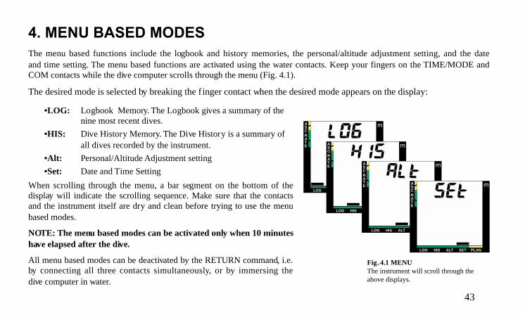
4. MENU BASED MODESThe menu based functions include the logbook and history memories, the personal/altitude adjustment setting, and the dateand time setting. The menu based functions are activated using the water contacts. Keep your fingers on the TIME/MODE andCOM contacts while the dive computer scrolls through the menu (Fig. 4.1).
The desired mode is selected by breaking the f inger contact when the desired mode appears on the display:
•LOG: Logbook Memory. The Logbook gives a summary of thenine most recent dives.
•HIS: Dive History Memory. The Dive History is a summary ofall dives recorded by the instrument.
•Alt: Personal/Altitude Adjustment setting
•Set: Date and Time Setting
When scrolling through the menu, a bar segment on the bottom of thedisplay will indicate the scrolling sequence. Make sure that the contactsand the instrument itself are dry and clean before trying to use the menubased modes.
NOTE: The menu based modes can be activated only when 10 minuteshave elapsed after the dive.
All menu based modes can be deactivated by the RETURN command, i.e.by connecting all three contacts simultaneously, or by immersing thedive computer in water.
Fig. 4.1 MENUThe instrument will scroll through theabove displays.
LOG HIS ALT SET PLAN
ASCRATE
m
LOG HIS ALT SET PLAN
ASCRATE
m
LOG HIS ALT SET PLAN
ASCRATE
m
LOG HIS ALT SET PLAN
ASCRATE
m
44
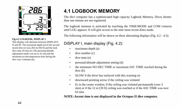
4.1 LOGBOOK MEMORYThe dive computer has a sophisticated high capacity Logbook Memory. Dives shorterthan one minute are not registered.
The logbook memory is activated by touching the TIME/MODE and COM contactsuntil LOG appears. It will give access to the nine most recent dives made.
The following information will be shown on three alternating displays (Fig. 4.2 - 4.5):
DISPLAY I, main display (Fig. 4.2):• maximum depth (a)
• dive number (c)
• dive time (e)
• personal/altitude adjustment setting (d)
• the minimum NO DEC TIME or maximum ASC TIME reached during thedive (b)
• SLOW if the diver has surfaced with this warning on
• downward pointing arrow if the ceiling was violated
• Er in the center window, if the ceiling was violated permanently (over 3min) or if the 12 m [39 ft] ceiling was reached or if the ASC TIME was over63 min.
NOTE: Ascent time is not displayed in the Octopus II dive computer.
Fig 4.2 LOGBOOK, DISPLAY IThis display will alternate between DISPLAYSII and III. The maximum depth (a) of the secondrecent dive (c) was 28.6 m [94 ft] and the totaldive time 29 min (e). The personal/altitudeadjustment mode was set to A1 (d) and theminimum no-decompression time during thedive was 3 minutes (b).
LOG HIS ALT SET PLAN
ASCRATE
m
DIVE
A1
DIVETIME
MAX
NO DEC TIME
a
b
c
d
e

45
DISPLAY II (Fig. 4.3):• average depth (a)
• surface interval time before dive (b)
• temperature at the maximum depth (c)
• dive time
DISPLAY III (Fig. 4.4):• dive entry time and date
The data of the most recent dive is shown first as DIVE 1 (the first dive in the memory).Preceding dives are recalled by touching the TIME/MODE and COM contacts. A brieftouch of the contact will bring you to the previous dive (DIVE 2), continuous contactscrolls backwards through the dives (DIVE 3, ... DIVE 9, DIVE 1 again etc.). Only DIS-PLAY I is shown, while scrolling the dives. The desired dive is selected by breaking thecontact when that dive appears on the display.
When new dives are added after nine dives, the oldest dives are deleted. The memorywill always retain the nine most recent dives. The contents of the memory will remaineven when the battery is changed (assuming that the replacement has been doneaccording to the instructions).
The average depth of the dive was 18.2 m[60 ft] (a), surface interval time before thedive 10 h 38 min (b) and temperature at themaximum depth 20°C [68°F] (c).
Fig 4.4 LOGBOOK, DISPLAY IIIThe dive started on the 18th of August(8) at 8:26 [when set to imperial version,A for a.m or P for p.m. are also shown inthe upper left corner of the display].
LOG HIS ALT SET PLAN
ASCRATE
m
C
SURF TIME
DIVETIME
a
b
c
LOG HIS ALT SET PLAN
ASCRATE
m

46
NOTE: The dive numbers shown in the dive planning mode do not match the onesshown in the logbook.
In the dive planning mode the dives are numbered according subsequent repetitivedives within a dive series, whereas in the logbook the dives are numbered accordingmemory address.
NOTE: The logbook contains test dives made in the factory. These dives will be deletedafter you have performed nine dives.
Fig 4.5 VIOLATION DISPLAYS INTHE LOGBOOK, DISPLAY IDisplay I shows SLOW warning (a) forsurfacing with the SLOW warning on, adownward pointing arrow for a violatedceiling (b), CEILING/ ASC TIMEsymbol (c) for decompression dive. Er inthe ASC TIME display (d) is shown, ifthe ceiling was violated over 3 min, or ifthe ceiling depth was over 12 m [39 ft]or if the ascent time was over 63 min.
LOG HIS ALT SET PLAN
ASCRATE
m
NO
DIVE
A1
CEILING ASC TIME
DIVETIME
MAX
a
b
cd

47
LOG HIS ALT SET PLAN
ASCRATE
m
A1
COM
TIMEMODE
PLANON
4.2 DIVE HISTORY MEMORYThe Dive History is activated by touching the TIME/MODE and COM contacts untilHIS appears. This mode will show (Fig. 4.6):
• the maximum depth ever reached (a)
• the total number of dives (b)
• the total accumulated dive time in hours (c)
999 dives and 999 hours of diving can be registered. When these maximum values arereached, the counters will start again from 0.
NOTE: The maximum depth will be zeroed, if the depth of 97.6 m [320 ft] is exceeded.
NOTE: The dive and dive time counters in the History Memory contain some test divesmade in the factory (e.g. DIVE 2, DIVE TIME 1 h). The maximum depth is, however,zeroed.
Fig. 4.6 DIVE HISTORYThe maximum depth ever reached is 33.0 m[108 ft] (a), the total accumulated dive time29 hours (c), and the total number of dives36 (b).
Fig. 4.7 PERSONAL/ALTITUDEADJUSTMENT SETTING, STEP 1The cur rent mode is A1.
LOG HIS ALT SET PLAN
ASCRATE
m
DIVE DIVETIME
MAXa
b
c

48
LOG HIS ALT SET PLAN
ASCRATE
m
A2A1A0
COM
TIMEMODE
PLANON
4.3 PERSONAL/ALTITUDE ADJUSTMENTSETTING
The current personal/altitude adjustment mode is shown when diving as well as on thesurface display. If the mode is not correct (see Chapter 3.6), it is imperative that the diverenter the correct selection before diving.
The new personal/altitude adjustment setting is entered in the following way. In thesefigures the contacts which are connected are shadowed.
1. Activate the personal/altitude adjustment setting mode by connecting the TIME/MODE and COM contacts continuously. Release your fingers immediately when Altappears on the display. Within a couple of seconds the present personal/altitude ad-justment setting is shown (Fig. 4.7).
2. Connect the PLAN/ON and COM contacts until all three personal/ altitude adjust-ment modes appear. Release your fingers immediately at this point. The current mode isnow blinking (Fig. 4.8). Wait at least two seconds but not more than four secondsbefore the next step.
3. Connect again the PLAN/ON and COM contacts until the blinking personal/altitudeadjustment mode starts to scroll. Release your fingers when the desired mode is blink-ing (Fig. 4.9). Wait at least two seconds but no more than four seconds before next step.
Fig. 4.8 PERSONAL/ALTITUDEADJUSTMENT SETTING, STEP 2The cur rent mode A1 is blinking. Lift yourfingers.
Fig. 4.9 PERSONAL/ALTITUDEADJUSTMENT SETTING, STEP 3Release your fingers when the desiredmode is blinking.
LOG HIS ALT SET PLAN
ASCRATE
m
A2A1A0
COM
TIMEMODE
PLANON

49
Fig. 4.10 PERSONAL/ALTITUDEADJUSTMENT SETTING, STEP 4The desired mode A2 is conf irmed byconnecting the TIME/MODE and COMcontacts.
4. Connect the TIME/MODE and COM contacts to confirm this new personal/altitudeadjustment mode (Fig. 4.10). The blinking will stop and the other mode indicators willdisappear.
5. The process is ended by the RETURN command, i.e. by connecting all three contactsat the same time (Fig. 4.11). The dive computer will return to the surface mode.
WARNING!ALWAYS RECHECK THE PERSONAL/ALTITUDE ADJUSTMENT SETTING TOENSURE THAT IT IS NOT SET FOR AN ALTITUDE LESS THAN THAT OF THEDIVE SITE!
Fig. 4.11 PERSONAL/ALTITUDEADJUSTMENT SETTING, STEP 5Return to the surface mode. Check thatthe selected mode A2 is displayed.
LOG HIS ALT SET PLAN
ASCRATE
m
A2
COM
TIMEMODE
PLANON
LOG HIS ALT SET PLAN
ASCRATE
m
A2
C
SURF TIME
DIVETIME
MAX
COM
TIMEMODE
PLANON

50
4.4 SETTING TIME AND DATEThe current date and time is read by connecting the TIME/MODE and COM contactsfor about two second, as described in Section 3.3.3, “Calendar Clock Function”.
Once the Time Setting mode is activated the principle when adjusting the clock is that:
• the TIME/MODE and COM contacts scroll through the different displays,
• the PLAN/ON and COM contacts change the values of the selected display.
In these figures the contacts which are connected are shadowed.
Thus, to correct the time, do as follows:
1. Activate the Time Setting mode by connecting the TIME/MODE and COM contactscontinuously to scroll through the menu. Release your fingers immediately when Setappears on the display. The Time Setting display will now be shown (Fig. 4.12).
2. The hour display star ts to blink immediately (Fig. 4.12). If you want to change it, keepthe PLAN/ON and COM contacts connected. The hours will start to scroll (Fig. 4.13).Release your f ingers immediately when the correct value is displayed. [To change the Aor P for a.m. or p.m. scroll the hours past 12:00].
3. To scroll through the minute, month and date, keep the TIME/MODE and COMcontacts connected. Release your fingers when the display you wish to change isblinking (Fig. 4.14). Repeat step 2 to change this value (Fig. 4.15).
Fig. 4.12 TIME SETTINGReady to adjust the hour reading (blinking).
Fig. 4.13 TIME SETTINGAdjusting the hour reading, PLAN/ON &COM.
CHANGEDISPLAY
CHANGEVALUE
COM
TIMEMODE
PLANON
LOG HIS ALT SET PLAN
ASCRATE
m
COM
TIMEMODE
PLANON
LOG HIS ALT SET PLAN
ASCRATE
m

51
NOTE: In case of the minutes and date, the change is made separately for both digits,as shown by the blinking digit. In case of the hours and month, the complete number ischanged simultaneously.
4. Repeat steps 2 and 3 to change any additional values.
5. Exit the Time Setting mode with the RETURN command, i.e. by connecting all threecontacts at the same time. First make contact between the PLAN/ON and TIME/MODEcontacts and after that with the COM contact.
NOTE: The clock is on (time is elapsing) when setting it and exiting the Time Settingmode. It is not possible to reset the seconds.
Remember to regularly check that the clock is on time especially when traveling todifferent time zones, as the entry time of all dives is stored in the logbook memory.
Fig. 4.14 TIME SETTINGScrolling through hours, minutes, monthand date, TIME/MODE & COM.
Fig. 4.15 TIME SETTINGAdjusting the ten minute reading (blinking),PLAN/ON & COM.
COM
TIMEMODE
PLANON
LOG HIS ALT SET PLAN
ASCRATE
m
COM
TIMEMODE
PLANON
LOG HIS ALT SET PLAN
ASCRATE
m

52
5. CARE AND MAINTENANCEThe dive computer is a sophisticated precision instrument. Remember to treat it as such! It has been designed to withstand therigors of scuba diving. It can be installed in a durable thermoplastic console boot and its display can be protected by areplaceable display shield.
The user should wash and rinse the unit in fresh water after every use. Protect it from shocks, extreme heat or direct sunlightand chemical attack. The instrument cannot withstand the impact of heavy objects like scuba cylinders, nor chemicals likeacetone and alcohols (ethanol, isopropanol).
NOTE: Keep the water contacts clean to assure correct operation of the dive computer. Store the instrument in a dry place.
NOTE: Frequently check the battery compartment for moisture through the transparent battery cover of the instrumentespecially after the battery replacement.
The dive computer should be serviced every two years or after 300 dives (whichever comes first) by an authorized dealer. Thisservice will include a general operational check and battery replacement. The service requires special tools and training.Therefore, it is advisable to contact an authorized Suunto dealer for biennial service. Do not attempt to do any servicing thatyou are not trained for.
The instrument will display a battery symbol as a warning when the power gets too low. When this happens, the dive computershould not be used until the battery has been replaced (see also chapter 3.3.1 /Battery Warning).

53
5.1 MAINTENANCEIf left without care for an extended period, a thin film (often invisible to the eye) will cover the unit. Much like the buildup onthe glass of an aquarium, this film is the result of organic contaminates found in both salt and fresh water. Suntan oil, siliconespray and grease will speed up this process. As a result of this buildup, moisture will be trapped next to the contacts and willnot allow your dive computer to operate properly.
The water contacts can be cleaned with a soft pencil eraser.
IMPORTANT: The instrument should be soaked, then thoroughly rinsed with fresh water after each dive.
If the unit is mounted in a console boot, the entire console should be soaked in fresh water and then rinsed. Make sure that allsalt crystals and sand particles have been flushed out of the console.
At the end of a dive trip, the dive computer should be rinsed thoroughly and then dried with a soft towel. If the unit is mountedinto a console boot, the computer unit will need to be removed from the console and cleaned before storage.
IMPORTANT: When removing the computer from the console, check the battery compartment for possible moisture or water.This is easily done through the transparent lid covering the compartment. DO NOT use the instrument if you detect anymoisture or water inside.

54
CAUTION!Do not use compressed air to blow water off the unit
Do not use solvents or other cleaning fluids that might cause damage
Do not test or use the dive computer in pressurized air.
5.2 BATTERY COMPARTMENT INSPECTIONFrequently check for leaks in the battery compartment. This is important especially after the battery has been replaced. If youfind moisture inside the transparent battery compartment lid, there is a leak.
A leak must be corrected without delay, as moisture will seriously damage the computer, even beyond repair. Suunto does nottake any responsibility for damage caused by moisture in the battery compartment, if the instructions of this manual are notcarefully followed.
In case of a leak immediately bring the instrument to an authorized Suunto dealer/distributor.

55
6. TECHNICAL DESCRIPTION
6.1 OPERATING PRINCIPLESThe Suunto dive computer is a multi-functional sport diving instrument, which provides information on depths, times anddecompression requirements. Its electronic microprocessor mathematically models the absorption and release of nitrogenduring all phases of diving, including ascents, surface intervals and repetitive dives.
WARNING!DO NOT ATTEMPT TO USE THE INSTRUMENT WITHOUT FIRST READING THE ENTIRE OWNER’S MANUAL! Thedive computer must be activated before diving and operated correctly to provide accurate and correct information.
NO-DECOMPRESSION LIMITS
The no-decompression limits displayed by the dive computer upon activation are for most dives to a single depth slightly moreconservative than those permitted by the U.S. Navy tables, Tables 6.1-6.2.

56
TABLE 6.1 NO-DECOMPRESSION TIME LIMITS (min) FOR VARIOUS DEPTHS [m] FORTHE FIRST DIVE OF A SERIES.
Personal/high altitude adjustment mode
Depth [m] A0 A1 A2
9 — 153 104
12 125 89 6615 71 57 4218 52 39 3021 37 29 2324 29 24 1927 22 18 1530 18 14 1233 13 11 936 11 9 839 9 7 642 7 6 545 6 5 5
57
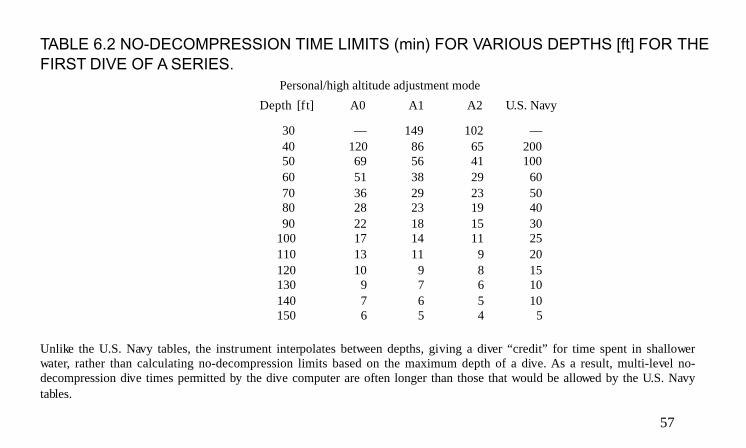
TABLE 6.2 NO-DECOMPRESSION TIME LIMITS (min) FOR VARIOUS DEPTHS [ft] FOR THEFIRST DIVE OF A SERIES.
Personal/high altitude adjustment mode
Unlike the U.S. Navy tables, the instrument interpolates between depths, giving a diver “credit” for time spent in shallowerwater, rather than calculating no-decompression limits based on the maximum depth of a dive. As a result, multi-level no-decompression dive times permitted by the dive computer are often longer than those that would be allowed by the U.S. Navytables.
Depth [ft] A0 A1 A2 U.S. Navy
30 — 149 102 —40 120 86 65 20050 69 56 41 10060 51 38 29 6070 36 29 23 5080 28 23 19 4090 22 18 15 30
100 17 14 11 25110 13 11 9 20120 10 9 8 15130 9 7 6 10140 7 6 5 10150 6 5 4 5

58
WARNING!THE USER SHOULD BE AWARE THAT ANY DIVE, INCLUDING ONES WITHIN THE U.S. NAVY TABLES OR DIVECOMPUTER LIMITS, DOES CARRY SOME RISK OF DECOMPRESSION SICKNESS.
COMPARTMENTS AND HALF TIMES
When you dive with the instrument, it measures and displays depths and times as your dive progresses. It shows you availableno-decompression time and possible decompression required based upon the following five factors:
1. your present depth,2. excess nitrogen absorbed during earlier portions of the dive,3. residual nitrogen remaining from previous dives,4. the no-decompression limits that apply to that depth,5. the personal/altitude adjustment mode in use.
Back on the surface, the dive computer will continue to calculate the no-decompression dive times available for various depthson the next dive. As the surface interval increases, so does the available dive time for the next dive.
To perform these calculations, the dive computer continuously models the absorption and release of excess nitrogen fromtheoretical compartments. Each compartment absorbs and releases nitrogen at a different rate. The compartments that absorband release nitrogen rapidly are believed to have a high tolerance for excess nitrogen, whereas compartments that absorb andrelease nitrogen more slowly are believed to be more sensitive.

59
The no-decompression limits in the U.S. Navy tables are based upon six theoretical compartments for single dives, and one compartmentfor surface intervals and repetitive dives. If you are familiar with table theory, you may know that they are characterized by half times(i.e. the time required for 50 % equilibration to a pressure change) ranging from 5 minutes to 120 minutes.
The instrument includes the same six compartments, and two additional compartments for an increased range of the mathematicalmodel. The calculations are based on all eight compartments for all phases of diving, including surface intervals and repetitive dives.The dive computer’s half times range from 2.5 to 320 minutes. The multi-level tissue calculations are based on modified Haldaneanprinciple.
ALTITUDE DIVING
The atmospheric pressure is lower at high altitudes than at sea level. After traveling to a higher altitude, the diver will haveadditional nitrogen in his body, compared to the equilibrium situation at the original altitude. This “additional” nitrogen isreleased gradually in time and equilibrium is reached within a couple of days.
Before high altitude diving the instrument must be set to high altitude diving mode to take this into account. The maximumpartial pressures of nitrogen allowed by the mathematical model of the dive computer are reduced according to the lowerambient pressure. As a result the allowed no-decompression limits are considerably reduced.
60
SURFACE INTERVALS
The dive computer requires a minimum surface interval of 10 minutes between dives. If a surface interval is shorter than 10minutes, the instrument dive counter and dive timer treat the next dive as a continuation of the previous dive. It adds the divetimes, and calculates no-decompression limits or decompression stops based on excess nitrogen absorbed on both dives. Inthis regard, it is similar to the U.S. Navy tables.
DEPTH LIMITS
WARNING!SUUNTO STRONGLY RECOMMENDS THAT SPORT DIVERS LIMIT THEIR MAXIMUM DEPTH TO 40 m [130 ft]!
However, the dive computer will calculate below that depth to provide a wide margin of flexibility if, through carelessness oremergency, you are forced to exceed this recommended depth limit for a dive.

61
6.2 TECHNICAL SPECIFICATION
DIMENSIONS AND WEIGHT (WRIST MODEL):• Diameter: 61.5 mm [2.42 in]
• Depth: 29 mm [1.14 in]
• Weight: 105 g [0.23 lb]
DEPTH GAUGE:• Temperature compensated pressure sensor
• Salt water calibrated (in fresh water the readings are about 3% smaller)
• Depth display range: 0 to 90 m [295 ft]
• Accuracy: ± 1 % FS (0 to 60 m [200 ft] at 20°C [68°F])
• Resolution: 0.1 m [1 ft]
TEMPERATURE DISPLAY:• Resolution: 1 °C [1.5°F]
• Display range: - 20 ... +50°C [- 40 ... +122°F]
• Accuracy: ± 2 °C [± 3.6°F] within 20 minutes of temperature change
CALENDAR CLOCK:• Accuracy: ± 2.5 s /24 h
• 24 h clock display [12 h display in imperial version]
• day and month

62
OTHER DISPLAYS:• Dive time: 0 to 199 min (999 dive hours in the history memory)
• Surface time: 0 to 39 h 59 min
• Dive counter: 0 to 255 dives (999 dives in the history memory)
• No-decompression time: 0 to 199 min (- - after 199)
• Ascent time: 0 to 63 min (- -/Er after 63) NOTE: Ascent time is not displayed in Octopus II dive computer.• Ceiling range: 3 to 9 m [10 to 30 ft]: blinking Er (ERROR) from 10 to 12 m [30 to 39 ft], after that
permanent Er (ERROR) mode
OPERATING CONDITIONS• Normal altitude range: 0 to 2400 m [8000 ft] above sea level
• Operating temperature: 0 to 40°C [32°F to 104°F]
• Storage temperature: -20°C to +50°C [-4°F to +122°F]It is, however, recommended that the unit be stored in a dry place at room temperature.
NOTE: Do not leave the instrument in direct sunlight!
BATTERY LUX/LUX S MODELS• One 3.0 V lithium battery (Varta CR 1/2 AA ), size 1/2AA (ANSI) or 1/2 R6 (IEC), spare part number K5546 +O-ring 26.7 mm x 1.78 mm 70 ShA, spare part numberK5508• Battery life: typically more than 3000 hours (at 20°C[68°F])
• One 3.6 V lithium battery, size 1/2 AA (ANSI) or 1/2 R6(IEC), spare part number K5504 + O-ring 26.7 mm x 1.78 mm70 ShA, spare part number K5508• Battery life: typically more than 2500 hours (at 20°C [68°F]).The use of the backlight shortens the typical expected batterylife.

63
7. WARRANTYNOTE: The warranty arrangements are different in different countries. Information is contained in the dive computerpackaging regarding the warranty benefits and requirements applicable to your purchase.The Suunto dive computer is warranted against defects in workmanship and materials for a period of two years after purchase to theoriginal owner subject to and in accordance with the terms and conditions set forth below:
This warranty does not cover damage to the product resulting from improper usage, improper maintenance, neglect of care, alterationor unauthorized repair. This warranty will automatically become void if proper preventive maintenance procedures have not beenfollowed as outlined in the use and care instructions for this product.If a claim under this or any other warranty appears to be necessary, return the product, freight prepaid, to your Suunto Dealer orqualified repair facility. Include your name and address, proof of purchase and/or service registration card, as required in yourcountry. The claim will be honored and the product repaired or replaced at no charge and returned in what your Suunto Dealerdetermines a reasonable amount of time, provided all necessary parts are in stock. All repairs made, not covered under the terms ofthis warranty, will be made at the owner’s expense. This warranty is non-transferable from the original owner.
All implied warranties, including but not limited to the implied warranties of merchantability and fitness for a particular purpose,are limited from date of purchase and in scope to the warranties expressed herein. Suunto shall not be liable for loss of use ofthe product or other incidental or consequential costs, expenses or damage incurred by the purchase. All warranties not statedherein are expressly disclaimed.
Some states do not allow the exclusion or limitation of implied warranties of consequential damages, so the above exclusionsor limitations may not apply to you. This warranty gives you specific legal rights, and you may also have other rights that varyfrom state to state.This warranty does not cover any representation or warranty made by dealers or representatives beyond the provisions of thiswarranty. No dealer or representation is authorized to make any modifications to this warranty or to make any additionalwarranty. Battery replacement is not covered by this warranty.
This Instruction Manual should be kept with your dive computer.

64
8. GLOSSARYAltitude dive A dive made at an elevation above 700 m [2300 ft] above sea-level.
Ascent rate The speed at which the diver ascends toward the surface.
ASC RATE Abbreviation for ascent rate.
Ascent time The minimum amount of time needed to reach the surface in a decompression dive.
ASC TIME Abbreviation for ascent time.
Ceiling On a decompression dive the shallowest depth to which a diver may ascend based on computernitrogen load.
Ceiling Zone On a decompression dive the zone between the ceiling and the ceiling plus 1.8 m [6 ft]. This depthrange is displayed with the two arrows pointing toward each other (the “hourglass” icon).
Compartment See “Tissue group”.
DCS Abbreviation for decompression sickness.
Decompression Time spent at a decompression stop or range before surfacing, to allow absorbed nitrogen toescape naturally from tissues.
Decompression sickness Any of a variety of maladies resulting either primarily or secondary from the formation of nitrogenbubbles in tissues or body fluids, as a result of inadequately controlled decompression. Commonlycalled “bends” or “DCS”.
Dive series A group of repetitive dives between which the instrument indicates some nitrogen loading ispresent. When nitrogen loading reaches zero the instrument deactivates.

65
Dive time Elapsed time between leaving the surface to descend, and returning to the surface at the end of adive.
Half-time After a change in ambient pressure, the amount of time required for the partial pressure of nitrogenin a theoretical compartment to go half-way from its previous value to saturation at the new ambientpressure.
Multi-level dive A single or repetitive dive that includes time spent at various depths and whose no-decompressionlimits are not determined solely by the maximum depth attained.
No-decompression time The maximum amount of time a diver may remain at a particular depth without having to makedecompression stops or remain below a ceiling during the subsequent ascent.
No-decompression dive Any dive which permits a direct, uninterrupted ascent to the surface at any time.
NO DEC TIME Abbreviation for no-decompression time limit.
Repetitive dive Any dive whose no-decompression time limits are affected by residual nitrogen absorbed duringprevious dives.
Residual nitrogen The amount of excess nitrogen remaining in a diver after one or more dives.
SURF TIME Abbreviation for surface interval time.
Surface interval time Elapsed time between surfacing from a dive and beginning a descent for the subsequent repetitivedive.
Tissue group Theoretical concept used to model bodily tissues for the construction of decompression tables orcalculations.

66