svf flow controls, inc - sani-tech west · pharmaceutical industry, svf flow controls, inc. now ......
TRANSCRIPT
The latest ASME/BPE guideline for valve and tubingdesigns used in biotech and pharmaceutical appli-cations provides process engineers with a reliable
and measurable valve selection criteria.
After years of successful installations throughout thepharmaceutical industry, SVF Flow Controls, Inc. nowoffers a fully compliant high purity ball valve that meetsthese stringent guidelines.
CleanFLOW™ ball valves are engineered to be a trueprocess piping component to specifically meet thedemanding processes found in the pharmaceutical, bio-tech, semiconductor, cosmetics, foods and other indus-tries where particle generation and contamination canthreaten the outcome of the product. The port opening ofthe valve’s flow path is dimensionally identical to the adja-cent tubing. This “Tube-ID” feature provides predictableflow rates and pressure drops and ensures thoroughcleaning and full drainability as mandated by ASME/BPE.
As a BPE-compliant product, CleanFLOW™ valves maybe specified and installed plant-wide making the processof design, construction, startup and maintenance easierto manage while helping to minimize overall project costs.
“We are pleased to recommend CleanFLOW™ valves tohelp you meet the critical demands of a BPE-compliant,high purity piping system.”
2
CleanFlow™ High Purity ball valves
add a new level of quality and per-
formance to High Purity and aseptic
processes.
Our design team, through years of
experience, has developed a valve
that is unparalleled for high purity,
high Vacuum, high cycle and may be
used in a wide range of pressure and
temperature applications.
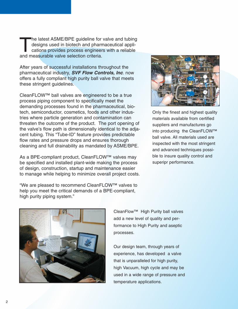
Only the finest and highest quality
materials available from certified
suppliers and manufactures go
into producing the CleanFLOW™
ball valve. All materials used are
inspected with the most stringent
and advanced techniques possi-
ble to insure quality control and
superipr performance.

3
TMC l e a nFLOW High-Purity Ball Valves
Solid 316L stainless steel ball with“Tube-ID” feature maintains fullflow rate, reduces pressure dropsand is fully drainable.
Bottom entry 316L precisionmachined stem with live loaded highcycle stem packing, automaticallyadjusts with pressure and tempera-ture fluctuations.
Encapsulated heavy duty stainlesssteel body bolts are protected fromoutside environment and are ideal for washdowns.
Interior standard finish of 20 Raensures cleanliness and lowfriction.Electro-polishing and finishes as low as 5 Ra available.
Integral Bosses allows for purgeports to be added for CIP or SIPapplications.
ISO 5211 Integral Mounting PadAllows for precise actuator mountingor secondary containment unit.
Vinyl covered stainless steel handleindicates direction of flow. Available in a variety of colors.
Fully encapsulated body sealsallows in line welding without disassembly, maintains sealingintegrity from high vacuum to highpressure and temperature applica-tions.
PTFE-TFM® seats feature non-slotted hygienic design eliminatingentrapment areas, smoother sur-face reduces torque and particlegeneration, FDA compliant andideal for clean steam applications.(PTFE-TFM® cavity filler available)
316L Stainless Steel Center Sectionallows easy access to internal valvecomponents without disturbing align-ment of tubing. Functions as bothvalve and union.
Variety of end connections availableincluding clamp end, buttweld, extended buttweld(ETO), socket weld,flush bottom tank pad, compressionends.

4
Typical CleanFLOW™ Applications
Pharmaceutical/Biotechnology
• High Purity Water• Clean Steam• WFI (water for injection) • Gas and Air Delivery• Cleaning Solutions• Alcohol
Semiconductor/Microelectronics
• Vacuum• High Purity Gases• Toxic Gases• Solvents (IPA, ketones)• Tool Hookup
Cosmetics
• Creams• Oils• Alcohol• Waxes • Detergents
Our exclusive quad-piston pneumatic actuator is ideallysuited for high density piping systems. The Compact4 ispowerful and lightweight and is available with a fullrange of modular control accessories.

5
Performance DataSeatsCleanFlow™ ball valves feature high-performance TFM seat material as standard.TFM is chemically modified PTFE that fills the gap between conventional PTFE and melt-processable PFA.Compared to conventional PTFE, TFM, has the following enhanced properties: Much lower deformationunder pressure (cold flow) at room and elevated temperatures. Lower permeability. May be used at higherpressures. Our seat specification reads as follows:
Seats - PTFE - TFM, (FDA, USP23 Class VI), Non-slotted, designed to meet ASME/BPE SD 3.6.1, SG-4.1.1.8, SG4.1.1.6.
Body SealsCleanFlow™ encapsulated PTFE seal design eliminates possible entrapment area between valve body andends, also facilitates inline welding without disassembly. Optional body seal material is available whenrequired.
CV Factors For CleanFLOW Ball Valves
Size Port CV
1/2 .37 83/4 .62 291 .87 661-1/2 1.37 192
**Pressure RatingC.W.P (cold working pressure)1/2 thru 2” 1500 PSI2-1/2 thru 4” 720 PSIW.S.P (working steam pressure)1/2” thru 4” 150 P.S.I-366˚F
Available Options & Accessories
Cavity Filler*- seats of PTFE-TFM®
eliminate thedead space between the ball and valve body.
Purge Ports- for C.I.P. or S.I.P. applications.
Polishing- Mechanical or electropolishing to5Ra.
Actuation- Pneumatic or electric automationpackages for ON/OFF or proportional control.
Flush Mounted Tank Pads- eliminate the deadleg between tank and valve.
Handles- variety of options including Locking,Oval, Extended, Spring return, Fusible link orColor coded.
Ends- variety of options including, Cherry BurrellI and Q-line, KF, socket weld tube, compression,150lb and 300lb flanges.
Materials- Hastelloy, Alloy 20, Monel, AL6XN orTitanium.
Secondary Containment Unit-Designed toretrofit existing valve. Prevents possible leaks tooutside environment.
Cryogenic-For applications to - 410˚F.
Pro-Spec™- SVFs innovative design team cancustomize valves for unique applications.
CV is defined as the number of U.S. gallons per minutethat water will flow thorough a valve at 1 p.s.i drop.
** Note: CleanFlow™ valves with TR ends are rated to TriClover specifications* Cavity filler are not recommended for steam service.
Size Port CV
2 1.87 4342-1/2 2.37 7233 2.87 11244 3.83 2100
CleanFLOW valves may be used at higherpressures and temperatures using eitherNRG or PEEK seats. Please consult factoryfor exact specifications.
Vacuum Rating.CleanFLOW valves provide excellentperformance under vacuum conditions andhave been helium leak tested to 1 x 10⁻⁹.Data upon request.
PTFE-TFM®
is a trademark of Dyneon
TORQUE DATA(IN.LB.)
Torque values shown represent ideal conditons.For exact figures consult factory

6
Surface Measurement
Conversion Chart
StandardGrit
150g
180g
240g
320g
27-32
µ-in.
18-23
14-18
8-10
30-35
µ-in.
20-25
15-20
9-11
.76-.89
µm
.51-.64
.38-.51
.23-.28
.68-.80
µm
.46-.58
.34-.46
.21-.25
Ra RMS
Measuring and specifying surface finish has, until recently, been left to a varying amount ofspeculation. The number of different standards being used by different equipment manufacturerhas created a great deal of confusion and misunderstanding throughout the industry. With theadvent of ASME/BPE the pharmaceutical and biotechnology industries finally have a standardthat can be universally applied.
*Table SF-5 Acceptance criteria for interior surface finishes of valve bodiesAnomaly or Indication Acceptance Criteria
Cluster of pits None accepted.Demarcation If 5% of the total area when visually inspected and Ra is met
Grit lines If Ra is met.
Nicks (per tube length) If depth < 0.010 in.Oxides Not accepted.Pits If dia < 0.020 in. and bottom is shiny.Porosity If dia < 0.010 in. and bottom is shiny.Scratches If length < 0.25 in., depth < 0.003 in., and Ra is met.
Surface cracks None accepted.Surface inclusion If Ra is met and there is no liquid penetrant indication.
Surface residuals None accepted.Surface roughness (Ra) See Table SF-6.
Water stains If not deposits.Weld dross None accepted.
General Note: All Ra readings are taken across the grain.
Note:(1) The average Ra is derived from two readings taken at different locations.
Other Ra readings are available if agreed upon between vendor and
owner/user.
Grit: Measures the number of scratches per linear inch of abrasive pad. Higher num-bers indicate a smoother finish.
RMS: Defined as Root Mean Square roughness, this method measures a sample forpeaks and valleys. Lower numbers indicate a smoother finish.
Ra: Known as the Arithmetic Mean, this measurement represents the average value of
all peaks and valleys. Lower numbers indicate a smooth finish.
Surface Designation µ-in. µm µ-in. µmSFV1 15 0.375 20 0.5SFV2 20 0.5 25 0.625SFV3 25 0.625 30 0.75
Surface Designation µ-in. µm µ-in. µmSFV4 10 0.25 15 0.375SFV5 15 0.375 20 0.5SFV6 20 0.5 25 0.625
Table SF-6 Ra Readings for ValvesMechanically Polished
Ra Average[Note (1)] Ra Max
Ra Average[Note (1)] Ra Max
Mechanically Polished andElectropolished
*Table SF-5,SF-6 from ASME/BPE-1997

7
High Purity Surface FinishThe importance of surface finish in the pharmaceutical and biotechnology industries is due toconcerns of possible microbial contamination. A smooth finish that is free of cracks, crevassesand inclusions is inherently easier to clean and maintain in an aseptic condition. The method ofachieving a smooth surface varies from pharmaceutical equipment manufacture to manufactureusing mechanical, chemical and electro polishing techniques.
Mechanical Polishing Procedures
CleanFLOW™ valves use a mechanical polishing technique that utilizes multiple passes withprogressively finer grits to produce the required standard finish. The parts are either hand heldduring the process or fixtured for spinning on polishing lathes or die grinders. Aluminum Oxideand Silicone Carbide are used for the coated abrasive grit. Buffing compounds are not used inour polishing process. After inspection, to ensure proper finish requirements are achieved, valveparts are ready to be either cleaned or electro polished before final assembly.
Electro Polishing
Electro polishing is the opposite of the plating process. It utilizes a combination of electric cur-rent and chemicals to remove surface material rather then add to it. It is the most effectivemethod of removing burr, folds, inclusions and other abnormalities. Peaks are removed quickerthan valleys because of the concentration of current on the peaks. This process leaves the sur-face extremely smooth and is far easier to clean by reducing the total area required to be steril-ized. This electrolytic process is frequently specified because of the broad range of inherentbenefits over mechanical polishing alone.
Electro Polishing Benefits
* Enhances Cleanability.* Passivates surface for greater corrosion resistance.* Removes inclusions and entrapped contaminants such as lubricants and grit particles.* Leaves surface with highly reflective luster finish.* Eliminates smeared or torn surface caused by machining or abrasives.
Diagrams show-ing progressiveremoval ofmetal by elec-tropolishing toprovide an evensurface profile.

8
Valve Components
Part No.
1
2
3
4
5
6
7
7A
8
8A
9
9A
10
11
12
Qty
1
2
1
1
2
2
1
1
1
1
2
3
1
1
2
Part
Body
Pipe Ends
Ball
Stem
Valve Seat
Valve Seal
Thrust Bearing
Stem LocationRing (3”& 4”)
Thrust Bearing
Thrust Bearing
Stem Packing
Stem Packing(2 1⁄2”- 4”)
Seal Protector
Gland Packing
Belleville Washer
Description
316L, ASTM A351-CF3M
316L, ASTM A351-CF3M
316L
316L
PTFE-TFM, NRG, PEEK, Cavity Filler PTFE-TFM
PTFE
PTFE
Stainless Steel 316
Peek
Peek
RT-TFE
PTFE
Peek
Stainless Steel 316L
Stainless Steel
Part No.
13
14
15
15A
15B
15C
16
17
18
18A
19
20
21
22
Qty
1
2
1
1
2
2
1
1
1
1
2
3
1
1
Part
Packing Nut
Lock Tab
Handle (1⁄2”-2”)
Wrench (2 1⁄2”- 4”)
Wrench Block
Hex Head Bolt
Lock Washer
Handle Nut (1⁄2”-2”)
Body Bolts
Body Bolt
Nuts
Stop Pin
Stop Plate
Seat Retainer
Description
Stainless Steel 316
Stainless Steel 309
Stainless Steel 304
Stainless Steel 304
Stainless Steel 304
Stainless Steel 304
Stainless Steel 304
Stainless Steel 316
Stainless Steel 316
Stainless Steel 304
Stainless Steel 304
Stainless Steel 304
Stainless Steel 304
Stainless Steel CF3M
1/2” - 2 1/2” 3” - 4”

9
Dimensions & Weights 1⁄2” - 21⁄2”
A A1 D E F G H M N P I.D. &PORT
TubeO.D.
ISO WEIGHT(lbs)
size
1/2”
3/4”
1”
1”-1/2”
2”
2”-1/2”
3.50
4.00
4.50
5.50
6.25
6.75
5.50
6.00
6.50
7.50
8.00
9.50
1.75
2.05
2.42
3.16
3.56
4.90
1.50
1.59
2.19
2.88
3.06
4.80
1/4 - 20
1/4 - 20
5/16 -18
3/8 -16
3/8 -16
M20
0.22
0.22
0.30
0.35
0.35
0.55
1.76
1.87
2.40
3.16
3.35
5.83
1.00
1.00
1.17
1.39
1.39
2.80
4.50
4.50
5.75
7.00
7.00
10.00
M5
M5
M5
M6
M6
M8
0.37
0.62
0.87
1.37
1.87
2.37
0.50
0.75
1.00
1.50
2.00
2.50
F03
F03
F04
F05
F05
F07
1.50
1.75
3.20
8.00
13.00
23.00
TR ETO
A A1 D F G H J L K T I.D. &PORT
TubeO.D.
ISO WEIGHT(lbs)
size
3”
4”
7.00
8.50
10.50
12.50
6.70
8.00
1”-14 UNS
1”-14 UNS
.745
.745
7.25
8.00
1.75
1.75
3.37
3.37
13.8
22.0
M10
M10
2.87
3.83
F10
F10
3.00
4.00
32
47
TR ETO
Dimensions & Weights 3” - 4”
For 1/4”, 3/8” and 6” contact factory
10
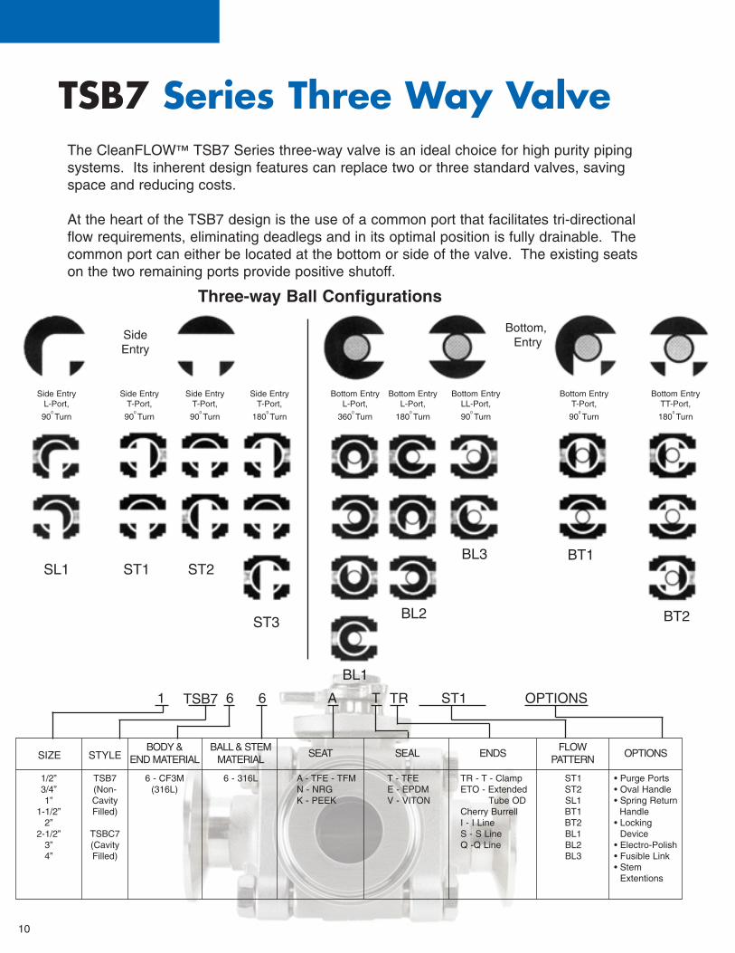
TSB7 Series Three Way ValveThe CleanFLOW™ TSB7 Series three-way valve is an ideal choice for high purity pipingsystems. Its inherent design features can replace two or three standard valves, savingspace and reducing costs.
At the heart of the TSB7 design is the use of a common port that facilitates tri-directionalflow requirements, eliminating deadlegs and in its optimal position is fully drainable. Thecommon port can either be located at the bottom or side of the valve. The existing seatson the two remaining ports provide positive shutoff.
SIZE STYLEBODY &
END MATERIALBALL & STEM
MATERIALSEAT SEAL ENDS
FLOW PATTERN
OPTIONS
1/2”3/4”1”
1-1/2”2”
2-1/2”3”4”
TSB7(Non-CavityFilled)
TSBC7(CavityFilled)
6 - CF3M(316L)
6 - 316L A - TFE - TFMN - NRGK - PEEK
T - TFE E - EPDMV - VITON
TR - T - ClampETO - Extended
Tube ODCherry BurrellI - I LineS - S LineQ -Q Line
ST1ST2SL1BT1BT2 BL1BL2BL3
• Purge Ports• Oval Handle• Spring Return
Handle• Locking
Device• Electro-Polish• Fusible Link• Stem
Extentions
1 6 6 A T TR ST1 OPTIONSTSB7
Three-way Ball Configurations
Side Entry
Side EntryL-Port,
900 Turn
SL1 ST1 ST2
ST3
Side EntryT-Port,
900 Turn
Side EntryT-Port,
900 Turn
Side EntryT-Port,
1800 Turn
Bottom EntryL-Port,
3600 Turn
Bottom EntryL-Port,
1800 Turn
Bottom EntryLL-Port,
900 Turn
Bottom EntryT-Port,
900 Turn
Bottom EntryTT-Port,
1800 Turn
Bottom,Entry
BL1
BL2
BL3 BT1
BT2

11
Dimensions & Weights 1⁄2” - 21⁄2”
3” & 4” consult factory for dimensions