svpwm based grid connected pv system with fuzzy mppt · pdf filesvpwm based grid connected pv...
TRANSCRIPT

International Journal of Research and Engineering Volume 2, Issue 4
15 http://www.ijre.org
ISSN 2348-7852 (Print) | ISSN 2348-7860 (Online)
SVPWM based grid connected PV system with fuzzy MPPT under partially shading
conditions 1Praveen Kumar. P,
2Jaiganesh.K
1Post Graduate Student,
2Assistant Professor
Department of Electrical and Electronics Engineering
K.S. Rangasamy College of Technology, Tiruchengode ,India [email protected],
Abstract— To convert solar energy more viable, the efficiency of solar array systems should be maximized. An
easier approach to maximizing the efficiency of solar array
systems is Maximum Power Point Tracking (MPPT). This
work proposes a fuzzy based controller which always attains
the global maximum point in shaded panels. The proposed
MPPT has been implemented by combining fuzzy logic based
MPPT with a scanning and storing system. The proposed
MPPT is able to reach the global maximum power point
(MPP) under any partial shading conditions. Moreover, the
controller exhibits a fast speed of convergence, having small
oscillation around the MPP during steady state. In order to use power produced effectively a three phase inverter with space
vector pulse width modulation was developed. Since it
contains only higher order harmonics and so the THD can be
maintained at the optimum value.
Keywords—MPPT, Shaded solar PV Panel, Fuzzy Logic,
Multiple Maxima
I. INTRODUCTION
The generation of energy in our modern industrialized
society is still mainly based on a very limited resource: fossil
fuels. As the world's energy demands rise and new sources for
fossil fuels become scarce, so the search for an alternative energy resources has become an important issue for our time.
A large amount of research has been done not only in the area
of nuclear power generation but also in the area of unlimited
energy sources such as wind power generation and solar
energy transformation.
The use of new efficient photovoltaic solar cells (PVSCs)
has emerged as an alternative measure of energy
conservation, renewable green power, and demand-side
management. Because of their high initial cost, PVSCs yet not
have been fully an attractive alternative for electricity users
who are able to buy cheaper electrical power from the utility grid. However, they can be used extensively for lighting,
water pumping and air conditioning in remote and isolated
areas, where the utility power is not available or is too
expensive to transport.
Modified fuzzy-logic controller for maximum power point
(MPP) tracking was proposed to increase photovoltaic (PV)
system performance during partially shaded conditions [1]. In
place of perturbing and observing the PV system MPP, the
controller will scan and stores the maximum power during the
perturbing and observing procedures. The controller provides
accurate convergence to the global maximum operating point
under different partial shadowing conditions. A technique based on GA was developed to extract the global maximum
point for PV panel under shade [2]. The characteristics of PV
array are affected by shading, temperature and solar
insolation. In reality, under partially shaded conditions, the P-V and I-V characteristics of solar array gets more complex
with multiple maxima in the characteristic curves. A new
method to track the global MPP based on controlling a dc to
dc converter connected to the output of PV array, such that it
behaves as a constant input-power load. The power–voltage
characteristic of PV arrays operating under partial-shading
conditions exhibits multiple local MPP[3]. A novel strategy of
maximum power point tracking for photovoltaic power
generation systems based on Fibonacci search algorithm to
realize simple control system to track the real maximum
power point even under non-uniform or for rapidly changing insolation conditions [4].
MATLAB-based modeling and simulation scheme
suitable for studying the I–V and P–V characteristics of a PV
array was developed under a non uniform insolation due to
partial shading [5]. The performance of a PV array is affected
by solar insolation, shading, temperature, and array
configuration. The PV arrays usually gets shadowed
completely or partially, by the neighboring buildings, passing
clouds, trees, towers, telephone and utility poles. During
partially shaded conditions, the PV characteristics becomes
more complex having multiple peaks. still, it is very important
to understand and predict them in order to extract the maximum possible power.
New MPPT method for PV array under PSC which is
based on IncCond method with step-size variation was
proposed [6]. Conventional popular MPPT methods are
effective under uniform solar irradiance. However, during
partially shaded conditions, these MPPTs may fail to track
the originall MPP because of the occurance of multiple local
maxima on the PV characteristic curve.
II. SOLAR PV CHARACTERISTICS
The solar cell is the semiconductor device that directly
converts the light energy to the electrical energy. Specifically, the output power of a solar array strongly depends on the
irradiance level of sunlight and ambient temperature. The
conventional model of a solar cell is the one diode model.
During uniform solar insolation, the output power of the solar
PV array is equal the total output power of all solar cells.
MPPT is used to track maximum power from a Solar PV
panel. But in non uniform insolation condition like shadow on
the solar panel, the region of shaded solar module starts
working as a load, and it can be expeled by using the bypass
and blocking diode[9]. If even one full cell is shaded, the
voltage of that module will drop to half of its un-shaded value
in order to protect itself. If enough cells are shaded, the module will not convert any energy and will in fact become a
tiny drain of energy on the entire system. The effect of
International Journal of Research and Engineering Volume 2, Issue 4
16 http://www.ijre.org
ISSN 2348-7852 (Print) | ISSN 2348-7860 (Online)
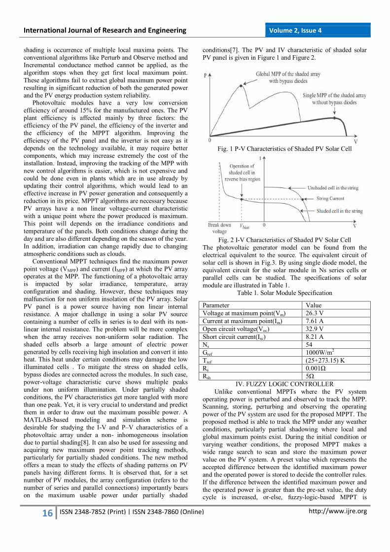
shading is occurrence of multiple local maxima points. The
conventional algorithms like Perturb and Observe method and
Incremental conductance method cannot be applied, as the
algorithm stops when they get first local maximum point.
These algorithms fail to extract global maximum power point
resulting in significant reduction of both the generated power
and the PV energy production system reliability. Photovoltaic modules have a very low conversion
efficiency of around 15% for the manufactured ones. The PV
plant efficiency is affected mainly by three factors: the
efficiency of the PV panel, the efficiency of the inverter and
the efficiency of the MPPT algorithm. Improving the
efficiency of the PV panel and the inverter is not easy as it
depends on the technology available, it may require better
components, which may increase extremely the cost of the
installation. Instead, improving the tracking of the MPP with
new control algorithms is easier, which is not expensive and
could be done even in plants which are in use already by updating their control algorithms, which would lead to an
effective increase in PV power generation and consequently a
reduction in its price. MPPT algorithms are necessary because
PV arrays have a non linear voltage-current characteristic
with a unique point where the power produced is maximum.
This point will depends on the irradiance conditions and
temperature of the panels. Both conditions change during the
day and are also different depending on the season of the year.
In addition, irradiation can change rapidly due to changing
atmospheric conditions such as clouds.
Conventional MPPT techniques find the maximum power
point voltage (VMPP) and current (IMPP) at which the PV array operates at the MPP. The functioning of a photovoltaic array
is impacted by solar irradiance, temperature, array
configuration and shading. However, these techniques may
malfunction for non uniform insolation of the PV array. Solar
PV panel is a power source having non linear internal
resistance. A major challenge in using a solar PV source
containing a number of cells in series is to deal with its non-
linear internal resistance. The problem will be more complex
when the array receives non-uniform solar radiation. The
shaded cells absorb a large amount of electric power
generated by cells receiving high insolation and convert it into heat. This heat under certain conditions may damage the low
illuminated cells . To mitigate the stress on shaded cells,
bypass diodes are connected across the modules. In such case,
power-voltage characteristic curve shows multiple peaks
under non uniform illumination. Under partially shaded
conditions, the PV characteristics get more tangled with more
than one peak. Yet, it is very crucial to understand and predict
them in order to draw out the maximum possible power. A
MATLAB-based modeling and simulation scheme is
desirable for studying the I-V and P–V characteristics of a
photovoltaic array under a non- inhomogeneous insolation
due to partial shading[8]. It can also be used for assessing and acquiring new maximum power point tracking methods,
particularly for partially shaded conditions. The new method
offers a mean to study the effects of shading patterns on PV
panels having different forms. It is observed that, for a set
number of PV modules, the array configuration (refers to the
number of series and parallel connections) importantly bears
on the maximum usable power under partially shaded
conditions[7]. The PV and IV characteristic of shaded solar
PV panel is given in Figure 1 and Figure 2.
Fig. 1 P-V Characteristics of Shaded PV Solar Cell
Fig. 2 I-V Characteristics of Shaded PV Solar Cell
The photovoltaic generator model can be found from the
electrical equivalent to the source. The equivalent circuit of
solar cell is shown in Fig.3. By using single diode model, the
equivalent circuit for the solar module in Ns series cells or
parallel cells can be studied. The specifications of solar
module are illustrated in Table 1.
Table 1. Solar Module Specification
IV. FUZZY LOGIC CONTROLLER
Unlike conventional MPPTs where the PV system
operating power is perturbed and observed to track the MPP. Scanning, storing, perturbing and observing the operating
power of the PV system are used for the proposed MPPT. The
proposed method is able to track the MPP under any weather
conditions, particularly partial shadowing where local and
global maximum points exist. During the initial condition or
varying weather conditions, the proposed MPPT makes a
wide range search to scan and store the maximum power
value on the PV system. A preset value which represents the
accepted difference between the identified maximum power
and the operated power is stored to decide the controller rules.
If the difference between the identified maximum power and
the operated power is greater than the pre-set value, the duty cycle is increased, or-else, fuzzy-logic-based MPPT is
Parameter Value
Voltage at maximum point(Vm) 26.3 V
Current at maximum point(Im) 7.61 A
Open circuit voltage(Voc) 32.9 V
Short circuit current(Isc) 8.21 A
Ns 54
Gref 1000W/m2
Tref (25+273.15) K
Rs 0.001Ω
Rsh 5Ω

International Journal of Research and Engineering Volume 2, Issue 4
17 http://www.ijre.org
ISSN 2348-7852 (Print) | ISSN 2348-7860 (Online)
applied[11]. In this case, the algorithm ensures that the MPPT
is not trapped by local maxima and quickly recovers the new
global maximum point during varying weather conditions.
The flowchart of the proposed method is shown in Fig.4,
where VPV, IPV are the PV output voltage and current
respectively, D is the duty cycle, Pmax is the global MPP, and
ΔPmax is a constant that identifies the allowable difference between the global maximum point and the operating power
point.
Three scanning and storing techniques are proposed to
identify the global maximum power during initial conditions
or varying weather conditions. The first technique is to
initialize the system with maximum duty cycle since the PV
output power usually takes some samples before reaching the
operating point at maximum duty cycle. The P–V
characteristic curve is scanned, and the global MPP is stored.
The second technique is to increase the duty cycle from a
minimum to a maximum value with a fixed step. In this case, the P–V curve is scanned, and the global MPP is stored. The
last technique is to apply a large initial perturbation step to
make a wide search range on the PV power locus. The
scanning and storing the PV power are accomplished during
perturbation and observation
Fig. 3 Proposed method flowchart
Table 2 Fuzzy Logic Rules
NB NS PS PB ΔPmax
NB PM PM NM NM
PS NS PS PS NS NS
PS NS NS PS PS
PB NM NM PM PM
NB PB PB PB PB
PB NS PB PB PB PB
PS PB PB PB PB
PB PB PB PB PB
V. SVPWM The circuit model of a typical three-phase voltage source
PWM inverter is shown in Fig. 4. S1 to S6 are the six power
switches that shape the output, which are controlled by the
switching variables a, a′, b, b′, c and c′. When an upper transistor is switched on, i.e., when a, b or c is 1, the
corresponding lower transistor is switched off, i.e., the
corresponding a′, b′ or c′ is 0. Therefore, the on and off states
of the upper transistors S1, S3 and S5 can be used to
determine the output voltage.
Fig. 4 Three-phase voltage source PWM Inverter.
Fig. 5 Switching vectors and sectors.
Therefore, space vector PWM can be implemented by the
following steps: � Step 1. Determine Vd, Vq, Vref, and angle (α)
� Step 2. Determine time duration T1, T2, T0
� Step 3. Determine the switching time of each transistor (S1
to S6)
As a result, six non-zero vectors and two zero vectors are
possible. Six nonzero vectors (V1 - V6) shape the axes of a
hexagonal as depicted in Fig. 8, and feed electric power to
the load. The angle between any adjacent two non-zero
vectors is 60 degrees. Meanwhile, two zero vectors (V0 and
V7) are at the origin and apply zero voltage to the load. The
eight vectors are called the basic space vectors and are
denoted by V0, V1, V2, V3, V4, V5, V6, and V7. The same transformation can be applied to the desired output voltage to
get the desired reference voltage vector Vref in the d-q plane.
The objective of space vector PWM technique is to
approximate the reference voltage vector Vref using the eight
switching patterns. One simple method of approximation is to
generate the average output of the inverter in a small period, T
to be the same as that of Vref in the same period.
International Journal of Research and Engineering Volume 2, Issue 4
18 http://www.ijre.org
ISSN 2348-7852 (Print) | ISSN 2348-7860 (Online)
Table 3. MOSFET ON/OFF STATES
Vector A+ B+ C+ A− B− C− VAB VBC VCA
V0 = {000} OFF OFF OFF ON ON ON 0 0 0 zero vector
V1 = {100} ON OFF OFF OFF ON ON +Vdc 0 −Vdc active vector
V2 = {110} ON ON OFF OFF OFF ON 0 +Vdc −Vdc active vector
V3 = {010} OFF ON OFF ON OFF ON −Vdc +Vdc 0 active vector
V4 = {011} OFF ON ON ON OFF OFF −Vdc 0 +Vdc active vector
V5 = {001} OFF OFF ON ON ON OFF 0 −Vdc +Vdc active vector
V6 = {101} ON OFF ON OFF ON OFF +Vdc −Vdc 0 active vector
V7 = {111} ON ON ON OFF OFF OFF 0 0 0 zero vector
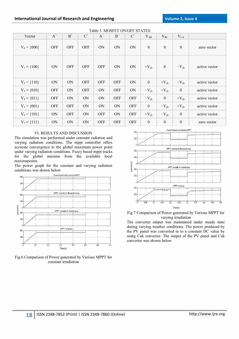
VI. RESULTS AND DISCUSSION
The simulation was performed under constant radiation and
varying radiation conditions. The mppt controller offers
accurate convergence to the global maximum power point under varying radiation conditions. Fuzzy based mppt tracks
for the global maxima from the available local
maximapoints
The power graph for the constant and varying radiation
conditions was shown below
Fig.6 Comparison of Power generated by Various MPPT for
constant irradiation
Fig.7 Comparison of Power generated by Various MPPT for
varying irradiation
The converter output was maintained under steady state
during varying weather conditions. The power produced by
the PV panel was converted in to a constant DC value by
using Cuk converter. The output of the PV panel and Cuk
converter was shown below

International Journal of Research and Engineering Volume 2, Issue 4
19 http://www.ijre.org
ISSN 2348-7852 (Print) | ISSN 2348-7860 (Online)
Fig.8 PV panel output
Fig.8 Converter output
Thus the converter output was maintained constant to 120V
under varying weather conditions.
The DC power thus produced was utilized properly by
converting the DC to three phase AC by using a three phase
rectifier. The switching techniques used in this paper to
operate the inverter was space vector pulse width
modulation.
Since SVPWM contains only higher order harmonics. Since
the space vector was defined for every half degrees, all the
lower order harmonica was eliminated. The higher order
harmonics was easily eliminated by using a low pass filter The inverter output containing higher order harmonics
before filtering was shown below
Fig. 9 Inverter output
Fig.10 FFT analysis before filtering action
Fig.11 Inverter output after filtering
Fig.12 FFT analysis after filtering
Conclusion
Thus the PV power produced was effectively utilized by using a three phase inverter employing SVPWM switching
techniques. The dc output was maintained constant by using
a Cuk converter employing fuzzy logic controller mppt. The
total harmonic distortion produced by the inverter before
filtering was 50.53%. After the filtering process the THD
gets reduced to 3.20%. It is evident that the SVPWM
produces a three phase output with having only higher order
harmonics. Thus the DC bus voltage was effectively utilized
by using SVPWM technique. It is evident that the SVPWM
has super harmonic performance
VII. REFERENCES
[1] Alajmi B.N, Ahmed K.H, Finney S.J and Williams
B.W, ―A Maximum Power Point Tracking Technique
for Partially Shaded Photovoltaic Systems in

International Journal of Research and Engineering Volume 2, Issue 4
20 http://www.ijre.org
ISSN 2348-7852 (Print) | ISSN 2348-7860 (Online)
Microgrids‖, IEEE Transactions on Industrial
Electronics, vol.60, no.4, pp.1596-1606, April 2013.
[2] Ali Reza Reisi, Mohammad Hassan Moradi and
ShahriarJamasb, ―Classification and comparison of
maximum power point tracking techniques for
photovoltaic system‖, Renewable and Sustainable
Energy Reviews, Volume 19, March 2013.
[3] Jae Hyeong Seo, Dong Seok Hyun and Chang Ho Choi ―A New Simplified Space–Vector PWM Method for
Three-Level Inverters‖ IEEE TRANSACTIONS ON
POWER ELECTRONICS, VOL. 16, NO. 4, JULY
2001
[4] Xiangsheng Li, Zhiquan Deng, Zhida Chen, and
Qingzhao Fei ―Analysis and Simplification of Three-
Dimensional Space Vector PWM for Three-Phase
Four-Leg Inverters‖ IEEE Transactions On Industrial
Electronics, Vol. 58, No. 2, February 2011
[5] Yu Liu Hoon Hong and Alex Q. Huang ―Real-Time
Calculation of Switching Angles Minimizing THD for
Multilevel Inverters With Step Modulation‖ IEEE Transactions On Industrial Electronics, Vol. 56, No. 2,
February 2009
[6] Amit Kumar Gupta and Ashwin M. Khambadkone ―A
Space Vector PWM Scheme for Multilevel Inverters
Based on Two-Level Space Vector PWM‖ IEEE
Transactions On Industrial Electronics, Vol. 53, No. 5,
October 2006.
[7] Behzad Vafakhah John Salmon and Andrew M.
Knight ―A New Space-Vector PWM with Optimal
Switching Selection for Multilevel Coupled Inductor
Inverters‖ IEEE Transactions On Industrial Electronics, Vol. 57, No. 7, July 2010
[8] Patel, H.; Agarwal, V., "MATLAB-Based Modeling to
Study the Effects of Partial Shading on PV Array
Characteristics," Energy Conversion, IEEE
Transactions on , vol.23, no.1, pp.302-310, March
2008.
[9] Shiva Moballeghand Jin Jiang, ―Modelling, Prediction
and Experimental Validations of Power Peaks of PV
Arrays under Partial Shading Conditions‖, IEEE
Transactions on Sustainable Energy, Vol. 5, no. 1,
pp.293-300, March 2014.
[10] Subudhi, B.; Pradhan, R., "A Comparative Study on Maximum Power Point Tracking Techniques for
Photovoltaic Power Systems," Sustainable Energy,
IEEE Transactions on , vol.4, no.1, pp.89-98, Jan.
2013.
[11] Shoji Fukuda and Yoshitaka Iwaji, ―Introduction of the
Harmonic Distortion Determining Factor and its
Application to Evaluating Real Time PWM Inverters,‖
IEEE transactions on Industry Applications.
[12] Yong Yang, Fang Ping Zhao, ―Adaptive Perturb and
Observe MPPT Technique for Grid- Connected
Photovoltaic Inverters‖, Procedia Engineering, Volume 23, 2011, Pages 468-473, ISSN 1877-7058.
[13] I. J. Balaguer, L. Qin, Y. Shuitao, U. Supatti, and P. F.
Zheng, ―Control for grid-connected and intentional
islanding operations of distributed power generation,‖
IEEE Trans. Ind. Electron., vol. 58, no. 1, pp. 147–
157,
Jan. 2011.
[14] José Rodríguez, Luis Morán, Pablo Correa and Cesar
Silva ―A Vector Control Technique for Medium-
Voltage Multilevel Inverters‖ IEEE TRANSACTIONS
ON INDUSTRIAL ELECTRONICS, VOL. 49, NO. 4,
AUGUST 2002
[15] B. Alajmi, K. Ahmed, S. Finney, and B.Williams,
―Fuzzy logic controlled approach of a modified hill
climbing method for maximum power point in
microgrid stand-alone photovoltaic system,‖ IEEE
Trans. Power Electron., vol. 26, no. 4, pp. 1022–1030, Apr. 2011.
[16] M. Miyatake, M. Veerachary, F. Toriumi, N. Fujii, and
H. Ko, ―Maximum power point tracking of multiple
photovoltaic arrays: A PSO approach,‖ IEEE Trans.
Aerosp. Electron. Syst., vol. 47, no. 1, pp. 367–380,
Jan. 2011.
[17] A. Safari and S. Mekhilef, ―Simulation and hardware
implementation of incremental conductance MPPT
with direct control method using Cuk converter,‖ IEEE
Trans. Ind. Electron., vol. 58, no. 4, pp. 1154–1161,
Apr. 2011.
[18] L.Wuhua and H. Xiangning, ―Review of nonisolated high-step-up DC/DC converters in photovoltaic grid-
connected applications,‖ IEEE Trans. Ind. Electron.,
vol. 58, no. 4, pp. 1239–1250, Apr. 2011.
[19] M. Liserre, T. Sauter, and J. Y. Hung, ―Future energy
systems: Integrating renewable energy sources into the
Smart power grid through industrial electronics,‖ IEEE
Ind. Electron. Mag., vol. 4, no. 1, pp. 18–37, Mar.
2010.
[20] Y. Mahmoud, W. Xiao, and H. H. Zeineldin, ―A
simple approach to modeling and simulation of
photovoltaic modules,‖ IEEE Trans. Sustain. Energy, vol. 3, no. 1, pp. 185–186, Jan. 2012.
P.Praveen kumar received his B.E
degree in Electrical and Electronics
Engineering from P.S.G college of
technology. Now he is currently
pursuing his M.E. degree in Power
Systems Engineering from
K..S.Rangasamy College of
Technology affiliated to Anna
University, Chennai. He is a member of ISTE and IEEE
K.Jaiganesh received B.E. degree in
Electrical and Electronics
Engineering from Periyar University,
Salem in 2002 and M.E. degree in
Power Electronics and Drives from
Anna University, Chennai in
2006.He is currently pursuing his
doctoral degree in Anna University, Chennai. He is working as an
Assistant Professor in the Department of Electrical and
Electronics Engineering at K.S.Rangasamy College of
Technology (Autonomous Institution). He is a Life member
of ISTE and ISEEE. His research interests are renewable
energy sources, inverters, converters.