sw 7.3 admin guide
TRANSCRIPT
SupportworksEnterprise Support Platform (ESP)Version 7.3
Administrator Guide

Copyright © 2007 Hornbill Systems Ltd. All rights reserved.
Information in this document is subject to change without notice, and should not be construed as a commitment by Hornbill Systems Ltd. Hornbill Systems Ltd assumes no responsibility or liability for any errors or inaccuracies that may appear in this document.
Except as permitted by the Licence Agreement pertaining to the software described in this document, no part of the document may be reproduced, stored in a retrieval system, or transmitted in any form or by any means, whether electronic, mechanical or otherwise, without the prior written permission of Hornbill Systems Ltd.
Supportworks is a registered trademark of Hornbill Systems Ltd. Acrobat is a registered trademark of Adobe Systems, Inc. Microsoft, Outlook, Windows, Windows NT and Windows XP are registered trademarks of Microsoft Corporation.
Contents of ESP Administrator GuideIntroduction to Supportworks Platform Administration 1What Is the Supportworks Platform? ..................................................................1What Is a Supportworks Application?.................................................................1This and Other Supportworks Publications.........................................................2The Topics Covered in this Guide.......................................................................2User Privileges ....................................................................................................3Supportworks Features ........................................................................................4
Customer Access Features ..........................................................................12
Organising the Database Tables 15Where to Start....................................................................................................15Populating the Tables ........................................................................................16Supportworks Data Management ......................................................................16
Case Scenario for Worked Examples .........................................................17
Importing Data from External Sources 19SQL Imports ......................................................................................................20
To Define a New SQL Import ....................................................................20To Define a New SQL Import Based On An Existing One........................28To Manage an Existing SQL Import...........................................................28
LDAP Imports ...................................................................................................28To Define a New LDAP Import..................................................................28To Define a New LDAP Import Based On An Existing One .....................37To Manage an Existing LDAP Import........................................................37
Text File Imports ...............................................................................................37To Define a New Text File Import .............................................................37To Define a New Text File Import Based On An Existing One.................45To Manage an Existing Text File Import....................................................45
Excel Imports ....................................................................................................45To Define a New Excel File Import............................................................45To Define a New Excel File Import Based On An Existing One ...............52To Manage an Existing Excel File Import..................................................52
Other Imports ....................................................................................................52Building a Worksheet of Call Profiles ........................................................53
To Import Call Profiles ...............................................................................55Advanced Import Techniques ...........................................................................56
Programmed Mapping Using JavaScript ....................................................56Pre- and Post-Import SQL Action on the Target Database ........................57Manipulating an Import and Its Mapping with JavaScript .........................58
Pre-Import JavaScript...........................................................................58Pre-Transformation JavaScript.............................................................59Post-Transformation JavaScript ...........................................................60Post-Import JavaScript .........................................................................60
Administrative Entities 61Service Level Agreements ................................................................................61
Introduction to Service Level Agreements .................................................61Example................................................................................................64Third Party SLAs .................................................................................65
Adding a New SLA ....................................................................................66Viewing and Modifying an Existing SLA ..................................................73Deleting SLA-related Items ........................................................................74Managing Third-Party SLAs ......................................................................74
Adding a New Third-Party Supplier ....................................................75Adding a New Third-Party SLA for a Supplier ...................................76Modifying a Third-Party Supplier’s Details ........................................77Removing a Third-Party Supplier ........................................................77Viewing a List of Third-Party SLAs....................................................77Modifying a Third-Party SLA’s Details ..............................................78Removing a Third-Party SLA ..............................................................78
Call Profiles.......................................................................................................79Introduction to Call Profiles .......................................................................79
Example................................................................................................81Call Profiles in Supportworks ITSM Applications.....................................82
Example................................................................................................82Call Profiles in Supportworks CS Applications .........................................83
Example................................................................................................83Adding a New Call Profile .........................................................................84Viewing and Modifying an Existing Call Profile .......................................86Deleting Existing Call Profile Tiers ...........................................................87
Workflow Templates.........................................................................................87
Introduction to Workflow ...........................................................................87Example................................................................................................89
Creating a New Workflow Template..........................................................90Viewing and Modifying an Existing Workflow Template .........................93Deleting an Existing Workflow Template ..................................................94
User-Related Data and Settings 95Skills ..................................................................................................................95
Adding a New Skill.....................................................................................96Viewing and Modifying the Details of an Existing Skill............................97Deleting an Existing Skill ...........................................................................97
Support Groups..................................................................................................97Adding a New Support Group ....................................................................98Viewing and Modifying the Details of an Existing Support Group .........100Deleting an Existing Support Group.........................................................100
Support Analysts .............................................................................................100Adding a New Support Analyst ................................................................101
Adding a New Support Analyst Based on an Existing Analyst .........118Viewing and Modifying the Details of an Existing Support Analyst .......119
Changing the Availability Status of a Support Analyst .....................119Changing a Password .........................................................................120Recovering an Analyst’s Password ....................................................120What Needs to Be Done After Changing System Privileges .............121Removing an Analyst’s Access to a Mailbox ....................................121Updating the Details of a Skill in an Analyst’s Skill Profile .............121Removing a Skill from an Analyst’s Skill Profile..............................121
Deleting an Existing Support Analyst ......................................................121Analyst Management Capabilities Relating to Each Role ..............................122
Managing E-Mail 123Managing Address Books ...............................................................................124
Creating New Contact Entries in Address Books .....................................126Modifying Contact Entries in Address Books ..........................................127Deleting Entries from Address Books ......................................................128Managing Distribution Lists in Address Books........................................128
Creating a New Distribution List .......................................................128Examining and Modifying the Contents of a Distribution List..........131
Importing Addresses from Microsoft Outlook .........................................131Managing E-Mail Templates...........................................................................133
Viewing and Editing Existing E-Mail Templates.....................................133Creating New E-Mail Templates ..............................................................134Deleting E-Mail Templates.......................................................................135Setting a Default E-Mail Template...........................................................136
Sending Bulk Mailshots ..................................................................................137
Managing Custom SQL Database Searches 139Creating a Custom Search ...............................................................................139Modifying a Custom Search............................................................................140Deleting a Custom Search ...............................................................................141
Managing the KnowledgeBase 143Placing Content into the KnowledgeBase .......................................................143
How to Publish Call Information..............................................................143How to Publish FAQ Information ............................................................147How to Publish External Documents........................................................148
Modifying Publications in the KnowledgeBase..............................................151Deleting Publications from the KnowledgeBase ............................................151Managing KnowledgeBase Catalogues...........................................................152
Managing Calendars 153Creating a Calendar .........................................................................................153Reconfiguring a Calendar................................................................................157Deleting a Calendar .........................................................................................157
Management Information and Reporting 159Running a Report in Real Time.......................................................................160Scheduling a System Report ...........................................................................162Viewing Information About a System Report.................................................168Modifying System Report Chart Characteristics ............................................169
Chart Characteristics.................................................................................171System Report Prompting ...............................................................................176Creating and Configuring System Reports......................................................177
To Build a System Report.........................................................................178The Options Available for a Simple List Report ...............................187
The Options Available for a Grouped List Report .............................188The Options Available for a Boxed Grouped List Report..................190The Options Available for a Value Counter Report...........................191The Options Available for a Grouped Value Counter Report............191
Using the WHERE Builder in a System Report .......................................192Setting Up User Prompts for a System Report...................................196
Querying Multiple Tables in a System Report .........................................198To Configure an Existing System Report .................................................201
Editing Clauses in a System Report’s Filter.......................................203To Create a Copy of an Existing System Report ......................................203
Sharing System Reports with Other Systems..................................................204To Export One or More System Reports ..................................................204To Import One or More System Reports ..................................................204
Managing System Reports...............................................................................205Creating a New System Report Folder .....................................................205Deleting a System Report Folder..............................................................205Renaming a System Report Folder ...........................................................205Moving a System Report to Another Report Folder.................................205Deleting a System Report .........................................................................206
Dashboard: Real-Time Data Display 207Starting Up ......................................................................................................207Refreshing the Displayed Data........................................................................208Switching to a Different Chart Layout ............................................................209Switching to a Different or Null Chart in a Pane ............................................209Creating and Configuring a Chart ...................................................................210
Basic Chart Definition ..............................................................................212Chart Characteristics.................................................................................213
Displayed Data ...................................................................................214Visual Attributes ................................................................................215Sizing Attributes.................................................................................216Lines and their Colours ......................................................................217Object Fill...........................................................................................218Background ........................................................................................219
Deleting a Chart...............................................................................................219
Operator Scripts 221What Operator Scripts Contain .......................................................................221How Operator Scripts Are Used......................................................................223Managing Operator Scripts .............................................................................225
Creating an Operator Script ......................................................................226Modifying an Operator Script...................................................................233Deleting Operator Scripts .........................................................................233Exporting and Importing Operator Scripts ...............................................233
To Export One or More Operator Scripts ..........................................233To Import One or More Operator Scripts ..........................................234
Customer Satisfaction Surveys 235Questionnaire Constituents .............................................................................235Questionnaire Usage .......................................................................................238Managing Customer Surveys ..........................................................................240
Creating a Customer Survey.....................................................................241How to Create a Section.....................................................................248How to Create a Matrix......................................................................249
Modifying a Customer Survey..................................................................250Deleting Customer Surveys ......................................................................251Viewing Survey Reports...........................................................................251
To Run the Reports for a Survey Campaign ......................................252Analysing the Survey Data by Respondent........................................254Analysing the Survey Data Statistically by Question ........................254Analysing the Free-Text Survey Data by Question ...........................257
Resetting the Data Gathered from Survey Campaigns .............................258Exporting and Importing Customer Surveys ............................................258
To Export One or More Customer Surveys .......................................259To Import One or More Customer Surveys .......................................259
On-Line Customer Access to Your Helpdesk 261Auto Responder E-Mail Commands ...............................................................261
Auto Responder E-Mail Templates ..........................................................263Testing the Auto Responder E-Mail Commands......................................264Configuring the Auto Responder..............................................................264
The Web-Based SelfService Application........................................................264Testing the Default SelfService Instance..................................................266
Managing SelfService Configurations......................................................266Configuring a SelfService Instance: Settings.....................................266Configuring a SelfService Instance: International Settings ...............271Configuring a SelfService Instance: Displayed Text Paragraphs ......273Configuring a SelfService Instance: System Privileges .....................275Creating a New SelfService Instance .................................................277
Publicising the SelfService URL ..............................................................278
Managing Analyst Access to the Helpdesk 281Analyst Access Licensing ...............................................................................281Nominating Analysts for Named Licence Usage ............................................282
Appendix A Analyst Rights and Default Settings 285System Privileges ............................................................................................285
Call Management Rights A.......................................................................287Call Management Rights B.......................................................................289System Management Rights .....................................................................291Desktop Workspace Rights.......................................................................293Data Dictionary Rights .............................................................................295Global SQL Database Rights ....................................................................296Database Management Rights ..................................................................296
E-mail Privileges .............................................................................................297Library Resources............................................................................................300Default Settings ...............................................................................................301
Appendix B Context Rights 305
Appendix C E-mail Template Variables 307Variables in Customer Notification Templates ...............................................308Variables in Auto Responder Templates.........................................................309
Template for Confirmation of Logged Call ..............................................310Template for Rejection Response to Logged Call ....................................311Template for Confirmation of Call Update...............................................311Template for Rejection Response to Call Update.....................................312Template for Call Status Report ...............................................................313Template for Open Calls Summary ..........................................................315Template for No Open Calls Response to Summary Request ..................317
Template for Response to Web Password Request ..................................318Template for Rejection Response to Any Information Request ...............318
Appendix D CTI Functionality and Number Specification 321Telephone Number Entry on a Form...............................................................321
Appendix E How SelfService Works 323
Introduction to Supportworks Platform Administration
1
Introduction to Supportworks Platform Administration
Supportworks is a support-management client/server application in which the server provides the central system functionality and its database holds all the support-related data, while the client provides the operational and administrative interfaces to the system, together with the customisation interfaces.
Each member of the support team has the client software installed on his or her workstation. These analysts use the client to handle calls and carry out other support-desk operations on a day-to-day basis. The support-desk administrator uses the client to initially set up the support aspects of the system and to continue to manage these as and when the necessity arises.
What Is the Supportworks Platform?Your Supportworks system is made up of two major components: the Enterprise Support Platform (ESP) and a specific application.
The Supportworks ESP provides the foundation for your chosen support-desk application, both client-side and server-side. It provides all the facilities that are common to all applications, and also provides access to any application. ESP facilities can be both administrative and usage-related.
What Is a Supportworks Application?The application parts of Supportworks consist largely of the customisable forms used for handling calls, for managing customer-related and asset-related data and, where applicable, for building business processes. You can see that these application facilities are also both administrative and usage-related.
An application is initially provided as a standard template that either a Hornbill consultant or your own developers then customise (or even radically redesign) in accordance with the precise requirements of your support function.
Introduction to Supportworks Platform Administration
2
This and Other Supportworks PublicationsThis Administrator Guide is designed to help you, in your capacity as system administrator, to set up the information-level foundations of a working helpdesk or service-desk system using facilities available on the Supportworks ESP, and to provide you with all the information necessary to maintain that platform. Equally, if you are a group manager in your organisation’s support team, you will find much of this guide useful in informing you how to make generic administrative adjustments within the context of your own support group.
To obtain information on the full spectrum of administrative functions available in Supportworks, you should read this guide in conjunction with the template-specific Administrator Guide that comes with the particular Supportworks application you have purchased.
To find out how to start up the client, how to use its most basic and universal controls and features, and how to access the main client views, please refer to the first chapter of the Supportworks ESP User Guide. If you are a group manager, that User Guide is again the place to look for finding out about the various day-to-day management functions that are available to you on the client.
As well as the template-specific Administrator Guide mentioned above, there is a template-specific User Guide provided with your system. This will describe and give instructions on call handling and all other aspects of day-to-day Supportworks user functionality that are specific to the application concerned.
Instructions on how to install or upgrade the Supportworks client are given in the Client Installation Guide. For information on the Supportworks server, please consult the Server Installation Guide and the Server Configuration Guide. All customisation aspects of Supportworks, including the use of form-design tools and data dictionaries, are covered in the System Customisation Guide.
The Topics Covered in this GuideAfter this introductory chapter, the next two chapters of this Administrator Guide first give you guidance on organising the database tables that form the core of the Supportworks application, and then tell you how to transfer data from external databases to these tables. Where appropriate, you are referred to
Introduction to Supportworks Platform Administration
3
the template-specific Administrator Guide, as database schemas vary between the different Supportworks applications.
In subsequent chapters, the kinds of entities designed to be held in the separate tables are described, and you are given precise instructions on how to manually create and maintain the records concerned. The remaining chapters deal mainly with the management of other essential (and not-so-essential) helpdesk facilities that are available to users from the client.
User PrivilegesThe vast majority of administrative operations on the platform are carried out using the main Supportworks client. As general user operations are also carried out using the client, two tiers of system privileges are provided to filter out inappropriate functionality in each individual user’s case.
The first tier of privilege is based on the user’s role, which can be System Administrator, Group Manager or Support Analyst. Role is concerned largely with the extent to which the user is allowed to manage the support team’s analyst records. A user’s role can be set only by someone in the System Administrator role, and it would be done in the Analyst Properties dialogue box (see Support Analysts on page 100).
The second tier of privilege is based on permissions, which allow the user to perform specific actions within the client. Permissions (which also include mailbox rights) can be set, for oneself and for others, only by users in the role of System Administrator or Group Manager. This would be done in the Analyst Properties dialogue box (see Support Analysts on page 100).
An extension of the second tier of privilege is mailbox-specific rights. These govern the ability of the user to (a) access particular shared mailboxes and (b) access particular e-mail functions within (or relating to) each personal or shared mailbox.
Another extension of the second tier of privilege is application-specific rights. Any Supportworks application (for example, ITSM) is likely to have functions, unique to it, that require rights control on a per-user basis. Many of these functions are sub-sets of generic functions, and any permission you may set for
Introduction to Supportworks Platform Administration
4
such a function will always override the permission set for the associated generic function.
Supportworks FeaturesSupportworks offers the following features to users:
• Familiar look and feel Various elements of the client’s user interface are strongly suggestive of Microsoft Office. The software offers, for example, familiarly styled shortcuts and toolbar buttons, drag-and-drop technology (as a quick way of moving message files around and of assigning support calls), a choice of docking or floating toolbars, and tree browsers with expandable levels. Many of the client’s separate parts run in their own independent windows, allowing you to carry on with an operation while keeping other information in view.
• Different ways of finding customer and asset records A customer’s or asset’s details can be found and displayed by various means, depending on your preference and on what you happen to be doing at the time.
• Easy-to-use and flexible call-logging facilities Calls for service or support are logged by analysts using suitable forms (defined by the application) to enter the required details into the database. Logged calls, while still outstanding, are listed in the appropriate view on the client. Subject to user rights, they can be listed in full for the entire helpdesk, by support group, or by individual analyst. The list can also be filtered according to predefined call-record criteria. Analysts can display the logged details for any call listed, and suitably update them as necessary. If analysts wish, they can place a call on hold, or cancel a call. Once a call has been confirmed by the customer as being resolved, an analyst would mark it as “closed”, which would result in its removal from the list of calls. The call’s details would then be viewable only via a call search (see below). It is also possible to mark a call as “resolved”, which would be appropriate when the analyst believes that the problem has been resolved, but no confirmation has yet been received from the customer. Such a provisionally resolved call would still be displayed in the list of calls. If an analyst has closed or cancelled a call by mistake, it is possible to reactivate it. Note that the ability to carry out any of the above call-related actions is dependent on the analyst having been given appropriate rights.
Introduction to Supportworks Platform Administration
5
• Start and end categorisations for calls Supportworks allows you to build two sets of codified call profiles that any member of the support team can quickly and conveniently select from, when logging or closing/resolving a call, to include in the call record concerned. A starting profile (or “problem” profile) categorises the reason for the call (perhaps expressed as the type of problem at hand), while an ending profile (or “resolution” profile) categorises the nature of the call’s resolution (perhaps expressed as the type of problem fix). These profiles are multi-tiered, so that the essence of any call can be defined and coded in a hierarchical manner. Such categorisations are useful when it comes to reporting on calls.
• Multiple call forms To cater for the different call-logging and call-progressing requirements of different groups of analysts, and for differences in the nature (or “class”) of calls themselves, facilities are provided for the creation of multiple designs of call forms. Members of the support team, when logging a call, would then be able to display only a form that is appropriate to their own group’s function. Within the scope of that function, they would be able to choose one form from several, depending on the type of service/support call they happen to be receiving.
• Quick-add technology This allows data entry on-the-fly. When an analyst is logging a call and has entered details of a hitherto unknown customer or asset into a form field, the client software prompts the analyst either to try again, or to create a new record in the relevant database table, allowing the data to become instantly available when a call from that customer is next logged. This record-creation ability can be restricted to certain analysts, if desired, by setting appropriate user rights to access specific tables.
• Auto-fill and auto-complete When an analyst enters call details on a form, the software verifies each entry and, if the analyst enters a recognised and unique customer or asset reference in an appropriate field, all other related fields are automatically filled. Additionally, where the analyst enters only partial data in a field, the software automatically completes the entry or, if more than one option is available, provides a pick-list from which the required entry can be selected.
• Call ownership and analyst skills The principle of call ownership is maintained throughout the application. You cannot log a call without it belonging to a support group, or to an individual support analyst. If you log a call without specifically assigning it to yourself, to another analyst or to a
Introduction to Supportworks Platform Administration
6
group, it will be automatically assigned to your own group. If you elect to specifically assign a call, a tree-view of the support organisation is displayed, showing the number of calls each support group and individual analyst is handling; this gives you an idea of current relative workloads as you try to decide on the most appropriate assignee. Furthermore, assuming that the system has been made aware of the specialist skills that the individual members of the support organisation possess, you will be able to list the analysts by skill (within any group) and therefore make an assignment decision on that basis as well.
• Workflow If your helpdesk operates in a highly managed environment where the various elements of the work necessary to resolve certain kinds of call are clearly stipulated and then allocated to different members of the team (or perhaps to just one analyst or group), Supportworks will assist you in organising the allocations according to basic workflow principles. When a call needs to be actioned, the workflow required for its resolution can be sub-divided firstly into “worklists”, and then into individual “work items” that are allocated to support analysts or groups. Each work item would be an actual task that an analyst must carry out. You can define worklists and work items on an ad hoc basis when logging a call, or you can predefine them within a named template, which any authorised member of the support team may subsequently apply to a call. All the worklists (and therefore work items) associated with a call must be completed before the call can be resolved or closed. The owner of any call having worklists associated with it will remain in overall control of the call until its closure.
• Quick-log calls This feature allows service/support calls with frequently recurring sets of characteristics to be created in advance for quick recall at any subsequent time. Quick-log calls are created as copies of actual call-logging forms (filled-in to the desired extent), and saved as named templates. Once created, a quick-log call can be selected by an analyst from a menu of such calls. This would display the relevant form, exactly as saved. The analyst would then be able to submit the form to the system immediately as a new call, without having to fill in the details first (although it would still be possible to edit the form). With the default rights, analysts can create and maintain quick-log call templates themselves, although it is possible to set up a scheme in which the templates are manageable by certain users only. There is no limit to the number of quick-log calls that can be created.
Introduction to Supportworks Platform Administration
7
• Scheduled calls This feature allows planned and routine support tasks (such as system backups) to be logged and assigned automatically as calls. The calls are set up in advance to activate on either a once-only or repeating basis. Like quick-log calls, scheduled calls are created by saving actual call-logging forms as named templates. Each scheduled-call template would include all the required call parameters. Once the template for a scheduled call has been created, the call is held dormant, only becoming active in the system at the first (or only) designated date and time.
• Batch call-handling facilities Most call-related operations (such as updating, closure, and so on) can be carried out on several calls at once. You just make a multiple call selection and click the same button as the one you might use for performing the action on a single call. Any data you may then enter, or any options you may set, for the chosen operation will be applied to your entire selection. Should an operation be invalid for any of the selected calls, you will be prevented from carrying it out for the batch as a whole.
• Audit trail Every action carried out by a support-team member, a customer or the system itself against a support call in Supportworks is fully audit-trailed and noted in the call’s diary. This information is displayable on the client when you review the call’s details, and provides a means of tracking the changes of status at every stage in the call’s life-cycle. Viewing the call diary additionally allows you to see which support analyst handled any given stage of the problem. Call-diary information is also displayable by customers via SelfService. With SelfService in use, analysts can, if they wish, disable public viewing of any particular update in which they intend to type comments of a sensitive nature.
• Service Level Agreements (SLAs) Supportworks supports a fully-configurable scheme of SLAs, escalations and alerts. The administrator sets the scheme up via the client, first defining the required SLA levels, and then assigning these (as necessary) to customers, assets, charge centres and/or problem profiles. When logging calls, analysts would either specify the SLA explicitly or via one of these assignments. The system itself, in subsequently tracking the calls, generates escalations and displays alerts as and when appropriate. The whole mechanism ensures that no call reaches a response or fix deadline without ample warning being issued to all support staff concerned.
• Computer Telephony Integration (CTI) Supportworks is fully TAPI 2.1 compliant for integration with modern digital telephone systems. If your
Introduction to Supportworks Platform Administration
8
organisation uses such a telephone system, and CTI is enabled on the client, it is possible for an analyst to auto-dial a customer by clicking a link on the customer’s active page. Conversely, on an incoming service/support call, the analyst can identify the caller via an on-screen monitor, on which they could then click a button to log the call, whereupon a new form would be opened and automatically populated with customer details derived from the first table record containing the incoming number.
• E-mail system Included in Supportworks is an independent e-mail system that will connect and exchange mail with any number of in-house mail systems that are MAPI, VIM or SMTP/POP3/IMAP4/LDAP compliant, and will also connect directly to the Internet through its own SMTP mail server. Among the features of the e-mail system, as seen on the client, are standard folders (such as Inbox, Outbox, Sent Items and Deleted Items), additional user-created folders, file attachments, template-based personal and group signatures, customisable displayed columns, preview text and a preview pane. Analysts can each have a personal mailbox, and can be authorised to access any number of shared mailboxes.
• Call functions from e-mail Supportworks allows analysts to initiate actions such as logging or updating a call from within any open e-mail message that has been submitted by a known customer. In the case of a call-log action, when the relevant form opens, the customer’s details are filled in automatically. When initiating any other call action, the analyst would be able to select the required call from a list of outstanding calls held against the customer. If the system has detected a call reference number in the message’s Subject field, it would know automatically which is the required call.
• Customer notifications by e-mail There are facilities available for automatically (or semi-automatically) notifying the customer by e-mail of actions taken by analysts at key stages in a call’s life-cycle, which include logging the call, updating the call, placing the call on hold and closing/resolving the call. When performing such an action, the analyst would be presented with an e-mail message window whose contents are based on an appropriate customisable template. This message would then be sent (after editing if necessary) to the customer concerned. By default, analysts maintain their own individual sets of e-mail templates, although it is possible to set up a single centralised scheme maintained by the administrator.
Introduction to Supportworks Platform Administration
9
• The KnowledgeBase Supportworks comes with the KnowledgeBase – a fully integrated database of support information derived automatically (or semi-automatically) from call details and the application’s user documentation, as well as from other sources and by manual entry. From the client, it is possible to conduct free-text searches of the KnowledgeBase, which include multi-word searches using selectable Boolean logic, and natural-language searches. You can also browse through the catalogues (four predefined and another four user-definable) that make up the KnowledgeBase, manage the indexing, and edit the content of individual records and documents. Since the KnowledgeBase uses a PHP interpreter to display much of its data, and the remaining data could easily be held as HTML and/or PDF documents, it would be quite natural to publish this information using a Web front-end as a way of promoting customer self-help. The SelfService application would make a good choice if you require such a front-end for customers. For maximum peace of mind, you have full control over which KnowledgeBase records or documents can and cannot be searched by customers.
• Reporting tools The unique architecture of Supportworks allows it to supply fully configurable, interactive, real-time statistical reports derived from any of the current information in the database. Reports, for example, on helpdesk calls by problem type over various time periods could be particularly useful. You can run supplied and custom reports from the client, with the option to run them immediately, or to schedule them to run automatically at one or more specified times. With a scheduled report, you can arrange for the output to be stored anywhere on your network, stored on an FTP server, or e-mailed to any number of mail recipients. Reports are organised hierarchically and selected using a tree-browser interface. An easy-to-use wizard is provided for designing your custom reports.
• Real-time wallboard display Supplied with Supportworks is an independently running client program known as Dashboard, which displays real-time call-related information in your chosen graphical format. The display is in the style of an Automatic Call Distribution (ACD) wallboard, with separate panes in the window simultaneously showing different information. Just as with reports, the displayed information is obtained from the Supportworks database but, unlike report outputs, Dashboard outputs are updated automatically at set intervals.
• Ticker display Another program running independently of the main client is the Ticker Bar, which produces, on client computers, a scrolling taskbar-
Introduction to Supportworks Platform Administration
10
based (or floating) ticker display of summary information feeds obtained at set intervals from the Supportworks database and/or the BBC website.
• Call searches From the relevant view in the Supportworks client, analysts can conduct field-based and free-text searches for logged service/support calls, whether or not currently open, using selectable Boolean logic where appropriate. It is possible to filter either kind of search by problem profile and/or by call status (including certain combinations of call status).
• Database searches The Custom Search Manager in the client allows suitably authorised team members with a knowledge of SQL to create named searches that are made available as executable entities for subsequent usage (subject to appropriate search rights).
• Customer issues Whenever your support team is receiving calls from a number of different users regarding the same problem, you have an “issue” to contend with. The Supportworks client allows analysts to deal with issues of two types: Hot Issues and Known Issues. Hot Issues would perhaps relate to the more critical problems that need urgent attention, while Known Issues might reflect lesser problems that your team is fully aware of but may be able to do very little about at the moment. You can link a number of existing calls to a particular issue. Any subsequently logged call can also be linked to the issue. When you close an issue, all calls associated with that issue are closed as well, and all affected customers can be notified via e-mail as usual. Current issues are visible to members of the support team in the same way as individual calls. They can also be displayed on SelfService pages, so that affected customers can be advised of known problems before logging a new call. (Note that, on Supportworks ITSM systems, the Issues feature is disabled, as this kind of functionality is available with “Problems”.)
• Instant overview of today’s helpdesk activity A particularly convenient view available in the client is one that includes at-a-glance summaries of the analyst’s and the group’s current workload, summaries of the analyst’s and the team’s mailbox content, a summary of all the major issues known to the system, and a highly visible indication of today’s date.
• Advanced spell-checking facilities Automatic and manual spell-checking and correction facilities are available in all major free-text-entry areas. Analysts can configure the operation of this feature precisely in accordance with their own wishes and requirements.
Introduction to Supportworks Platform Administration
11
• Preconfigured Web server and scripting language Supportworks ships with a fully preconfigured Web server, based on Apache for Win32, to provide the technologies required for the Web-style functioning of many parts of the application. Also included preconfigured is PHP, a versatile server-side scripting language that offers a means by which Supportworks can connect to, and integrate with, a broad range of database and information systems.
• Troubleshooting system for users The Operator Scripts feature allows you to set up a decision-based troubleshooting system within Supportworks that provides first-line support staff with suggested resolutions to common problems by means of a wizard-style interface.
• Customer-satisfaction surveys The optional Customer Surveys feature provides you with facilities for creating transactional on-line survey campaigns that you can use to gauge your customers’ satisfaction with the helpdesk service you give them. When analysts are resolving or closing calls, they can have the system automatically e-mail the customer with a URL link to the selected survey page for them to complete the questionnaire you have built.
• GUI customisation using data dictionaries A data dictionary provides a central repository of customisation settings for the Supportworks client. These settings include database table column names, form-layout and field-functionality definitions, menu elements, tree-browser definitions, search fields and application icons. If you are suitably authorised, you can change the customisation settings by means of the Data Dictionary Editor, the relevant Form Configuration tool and/or the easy-to-use Form Designer, all of which are accessible from the client. The data dictionary is the chief element that distinguishes one Supportworks application from another, or one application variant from another. Multiple data dictionaries allow you to provide support-group-specific customisations that will present a different user interface to each group within the support team, thus giving optimal configuration for team members. As the customisation facilities are an integral part of the client, and the application uses Non-Polling Architecture (NPA), any changes you make that do not actually alter database table structures are applied dynamically, which means that there is no need for you to then shut down the server, or for users to log out of the system. When you are using the Form Designer and you save changes you have made to a form layout, the changes are immediately applied to any forms that are currently open on your desktop.
Introduction to Supportworks Platform Administration
12
With a Form Configuration tool, the changes are applied the next time you open a form.
• Two types of Web-browser interface (Not applicable to Supportworks Essentials) There is no need to be at your own desk in order for you to be able to carry out many of the usual day-to-day analyst activities associated with Supportworks. The full-sized Web-browser interface provided with the application allows you to log, examine and progress calls from any Web-connected computer by using nothing more than a standard Web browser, while the PDA Web Client interface (currently supported on Supportworks ITHD only) allows you to do the same from any Web-enabled personal organiser. The full-sized interface, known as the Analyst Portal, is designed to provide a user experience that is as identical as possible to the one provided by the most essential parts of the native client’s user interface. One mode of the Analyst Portal employs Microsoft ActiveX controls to automatically replicate substantial parts of the native client’s customisable dialogues, whereas the more secure non-ActiveX mode relies on PHP developers to achieve the same result.
Customer Access Features
To further enhance the helpdesk service you provide to your customers, you can allow them direct access to the support system, so that they could, for example, log their own support calls. Such a means of customer empowerment should substantially improve the efficiency of your support organisation by reducing the volume of telephone calls to your helpdesk or service desk.
There are two possible on-line methods by which customers (having been given the appropriate rights) can interact with Supportworks:
• Via e-mail commands to the system By entering a suitable command in the Subject line of an e-mail message addressed to your support organisation, customers will be able to log calls, track the status of any call (or all calls) belonging to them, and request their SelfService password. The Supportworks server responds automatically to such requests, sending back the relevant information, an acceptance message or a rejection message, as appropriate. These standard responses are based on sets of user-definable templates, which are accessible for editing from the Supportworks client. You can have a separate set of templates for each shared mailbox on the system.
Introduction to Supportworks Platform Administration
13
• Via the Supportworks SelfService application By accessing the password-protected SelfService pages on your website using any standard Web browser, customers with the relevant set of rights will be able to log support calls, track the status of their calls, update their calls and search the KnowledgeBase.
As with calls logged by analysts, Supportworks automatically generates a unique Call Reference number for each support call logged via SelfService or via e-mail. As no distinction is made between calls logged in different ways, all open calls relating to a given customer will be available for status-tracking and updating by that customer (or, equally, by analysts). For detailed information on configuring these facilities on your helpdesk system, refer to the chapter entitled On-Line Customer Access to Your Helpdesk on page 261.

Introduction to Supportworks Platform Administration
14
Organising the Database Tables
15
Organising the Database Tables
One of the most important aspects of installing any new helpdesk or service-desk application is ensuring that it represents, as closely as possible, the environment it is actually monitoring and controlling. Thus, the configuration of Supportworks must reflect the support environment in place within your organisation.
In Supportworks, your support environment and its operational requirements are defined largely by the content of its database tables, and, to a lesser extent, by appropriate settings in the client and server. Database content would include a definition of your support hierarchy, and information relating to analysts, customers, assets, Service Level Agreements and so on.
This chapter of the Administrator Guide, in conjunction with the relevant chapter of your template-specific Administrator Guide, gives you guidance on organising initial data input into your Supportworks tables, provides you with an outline of these tables, and gives you a recommendation as to the sequence in which to best carry this out.
Where to StartOrganising the implementation of new helpdesk software always requires a lot of consideration and planning. Perhaps the first issue to consider is the extent to which you can import data into the Supportworks database tables, rather than having to manually enter it. If you have just upgraded your previous helpdesk application to Supportworks, the likelihood is that you will already have some kind of customer table and, possibly, other tables whose records are suitable for importing into Supportworks. See the chapter entitled Importing Data from External Sources on page 19 for details of the Data Import Manager utility that comes with Supportworks and allows you to define and run any number of imports.
Another issue to think about is the possibility of regularly importing data from another database currently in use elsewhere in your organisation. Once you have defined the required imports using the Data Import Manager, you can schedule
Organising the Database Tables
16
them to run at appropriate times using the Server Configuration utility. Please refer to the Server Configuration Guide for information about the Scheduler.
If you wish to import data from other databases, you will probably have to consult people within your organisation who have expert knowledge of these, so that you will be able to properly map the data to the relevant columns of the Supportworks tables.
Any degree of importation that you can carry out will certainly save you a lot of time: this is especially true of tables that contain a very large number of records. However, there will always be at least some tables that you will have to populate, or just “top up”, manually. Normally, therefore, you are advised to take into account the order in which to populate them. Note that you may not need to use all of the tables that Supportworks provides.
Populating the TablesSupportworks uses various database tables to hold the details of your support environment, many of which are interrelated. Thus, certain data held in some of these tables will be values selected from the tables related to them, which means that these related tables would, for maximum convenience, have to be populated first. Failure to follow the optimal order in such cases might mean more manual record updates having to be done.
It is therefore worth taking note of the table interrelationships in your particular application if you wish to maximise ease of table setup. For a basic summary of these, please see the chapter on populating the tables in the template-specific Administrator Guide. In that chapter, having pointed out the table interrelationships, we are then able to suggest a logical order in which to populate the database tables overall.
Supportworks Data ManagementThe database tables that you initially need to populate by one means or another can be managed manually at any subsequent time. There are also other, less crucial and totally independent, tables, whose populating can be left until later. These, too, will be manageable at any time.
Organising the Database Tables
17
Management of those kinds of data that are common to all applications is covered in the following chapters, after the chapter dealing with data importation.
To read about template-specific data management, please see the Administrator Guide for the template concerned.
Case Scenario for Worked Examples
To help you focus on real-world requirements, worked examples have been provided in some of the following chapters for the more involved kinds of data management. The overall case scenario on which these examples are based is set out below.
A company by the name of Data Organisation Information Technology (DO IT for short) are in the process of installing and configuring Supportworks at their Headquarters. DO IT have to provide in-house hardware support to other DO IT employees, and also software support for their project-management application, called Fast Access Schedule Tool (FAST), to external customers. They have a number of support technicians who handle the in-house hardware issues, and a group of FAST support technicians who look after the external customers. Additionally, they have a mobile support team who visit customer sites, installing and supporting FAST. Each of these three groups has a group manager who is responsible for co-ordinating the support activities of the group. DO IT additionally have a helpdesk administrator who handles any escalated support calls and oversees the entire support operation.

Organising the Database Tables
18
Importing Data from External Sources
19
Importing Data from External Sources
Certain kinds of data, such as customer data, that need to be held in the Supportworks database may already exist elsewhere in your organisation. This means that, rather than having to engage in the laborious and error-prone task of rekeying all the data manually, you or your Hornbill consultants can populate Supportworks by using an automatic bulk-transfer method. Such a method is provided in the form of a stand-alone utility installed along with the Supportworks server. By means of this utility, which is called the Data Import Manager, it is possible to simply and reliably import data into Supportworks tables from any standard SQL data source, any LDAP-compatible directory service (such as Microsoft Active Directory – ADS), any structured text file (such as CSV) or any Microsoft Excel file. In addition, there is a specific facility for importing call profiles from a Microsoft Excel file, with the profiles having been entered manually on a worksheet in a prescribed format. Call profiles are administrative entities described in the section entitled Call Profiles on page 79 in the next chapter.
For data sourced from other databases, the Data Import Manager allows you firstly to predefine your import by specifying the source connection (or the source file and its structure), stipulating the required source elements and mapping these to table columns in the Supportworks database. It then allows you to either run or schedule the import.
Using the Data Import Manager, you can predefine four kinds of import, each pertaining to one of the four types of data source supported: SQL, LDAP, text or Excel file. The process of predefining an import is broadly the same for all four types, differing only in specific detail where appropriate.
For manually entered call-profile data, you would perform imports on an ad-hoc basis. These kinds of Excel imports cannot be scheduled.
The following five sections describe the respective import processes.
To run the Data Import Manager, select Start > Programs > Supportworks Server > Data Import Manager.
Importing Data from External Sources
20
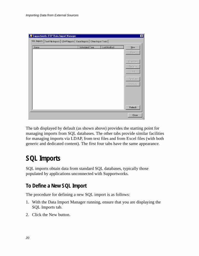
The tab displayed by default (as shown above) provides the starting point for managing imports from SQL databases. The other tabs provide similar facilities for managing imports via LDAP, from text files and from Excel files (with both generic and dedicated content). The first four tabs have the same appearance.
SQL ImportsSQL imports obtain data from standard SQL databases, typically those populated by applications unconnected with Supportworks.
To Define a New SQL Import
The procedure for defining a new SQL import is as follows:
1. With the Data Import Manager running, ensure that you are displaying the SQL Imports tab.
2. Click the New button.
Importing Data from External Sources
21
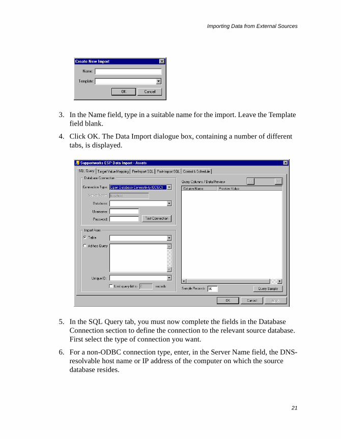
3. In the Name field, type in a suitable name for the import. Leave the Template field blank.
4. Click OK. The Data Import dialogue box, containing a number of different tabs, is displayed.
5. In the SQL Query tab, you must now complete the fields in the Database Connection section to define the connection to the relevant source database. First select the type of connection you want.
6. For a non-ODBC connection type, enter, in the Server Name field, the DNS-resolvable host name or IP address of the computer on which the source database resides.
Importing Data from External Sources
22
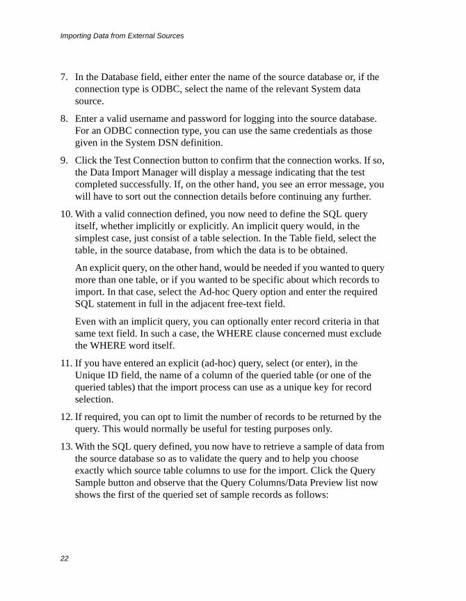
7. In the Database field, either enter the name of the source database or, if the connection type is ODBC, select the name of the relevant System data source.
8. Enter a valid username and password for logging into the source database. For an ODBC connection type, you can use the same credentials as those given in the System DSN definition.
9. Click the Test Connection button to confirm that the connection works. If so, the Data Import Manager will display a message indicating that the test completed successfully. If, on the other hand, you see an error message, you will have to sort out the connection details before continuing any further.
10. With a valid connection defined, you now need to define the SQL query itself, whether implicitly or explicitly. An implicit query would, in the simplest case, just consist of a table selection. In the Table field, select the table, in the source database, from which the data is to be obtained.
An explicit query, on the other hand, would be needed if you wanted to query more than one table, or if you wanted to be specific about which records to import. In that case, select the Ad-hoc Query option and enter the required SQL statement in full in the adjacent free-text field.
Even with an implicit query, you can optionally enter record criteria in that same text field. In such a case, the WHERE clause concerned must exclude the WHERE word itself.
11. If you have entered an explicit (ad-hoc) query, select (or enter), in the Unique ID field, the name of a column of the queried table (or one of the queried tables) that the import process can use as a unique key for record selection.
12. If required, you can opt to limit the number of records to be returned by the query. This would normally be useful for testing purposes only.
13. With the SQL query defined, you now have to retrieve a sample of data from the source database so as to validate the query and to help you choose exactly which source table columns to use for the import. Click the Query Sample button and observe that the Query Columns/Data Preview list now shows the first of the queried set of sample records as follows:
Importing Data from External Sources
23
The record is displayed as a list of column names, together with their respective values. You can display other records in the set by means of the >> and << buttons at the top right.
14. Once you have decided which columns should be included in the import process, select their associated checkboxes. Only these columns will now be available to you for mapping to the target Supportworks database, as described in the following steps.
15. To proceed with the mapping, first select the Target Value Mapping tab.

Importing Data from External Sources
24
16. In the Database field, select the database into which you want the data imported.
17. In the Table field, select the table, within that database, into which you want the data imported. Note that the Unique Key field is now filled by default with the name of the selected table’s primary-key column, and that the Target Columns list is populated with all the columns of that table.
18. If necessary, you can manually select a unique key other than the primary key.
19. By virtue of the default Data Update Operations setting, the import process will both create (insert) and update records in the Supportworks database, as dictated by their absence or presence with respect to the corresponding source records. If, however, you wish to preserve the Supportworks data on this import, you should enable the “Only allow inserts” option. Alternatively, if you wish to prevent further Supportworks records being created on this import, you should enable “Only allow updates”.
Importing Data from External Sources
25
20. You are now ready to map your previously selected source table columns to columns of your selected target table. First select the checkboxes associated with your proposed target columns.
21. Highlight one of the selected target columns and click anywhere in the Value Transformation and Assignment field.
22. For a simple mapping, click the Insert Value button and, from the menu that pops up, select the source table column that you want mapped to the target column you have highlighted. Notice that the chosen column appears in the field in the form db.<column>.
For more complex mappings, you would have to manually type the required expression into the Value Transformation and Assignment field. See the section entitled Advanced Import Techniques on page 56 to find out what is possible here using JavaScript.
23. If you want the import process to skip each source record where there is no value assigned for the column (or for any column in the expression), enable the “Non-empty value required” option. This will always be enabled if the target column being mapped is a unique key.
24. If you have entered an expression manually into the Value Transformation and Assignment field, you can confirm correct resolution of the currently highlighted target column’s values by clicking the Check Syntax button. This will display, one at a time in the Preview Value Assignment field, the values for that column as computed by the expression, using the set of sample data you previously queried. You can use the >> and << buttons to show the following and preceding values, respectively.
25. Repeat step 21 to step 24 for each of your proposed target columns.
26. Click Apply.
27. Having completed the mapping, you can now run or schedule the import. First select the Control & Schedule tab.
Importing Data from External Sources
26
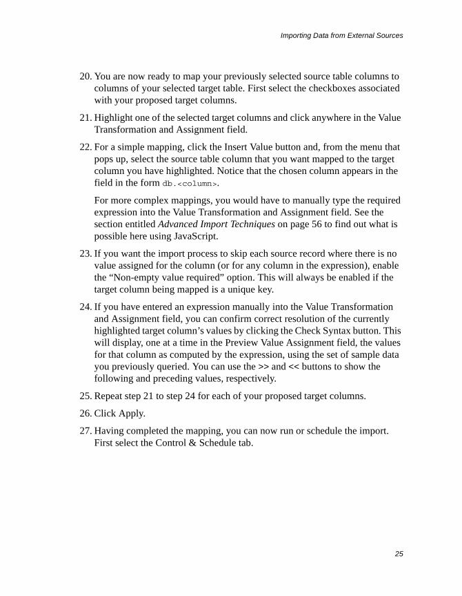
28. If you wish to run the import immediately, click the Run Import Now button. A separate window is displayed, in which you can see the import’s progress.
29. On completion of the import, you can click View Log in the progress window to view the details of the import process. Note that this is a cumulative log, which means that the current import details are appended to any existing details already logged in this session. (The log will be deleted when you exit from the Data Import Manager.) You can also view the log by using the View Log File button located next to the Run Import Now button.
30. Click Close to dismiss the progress window.
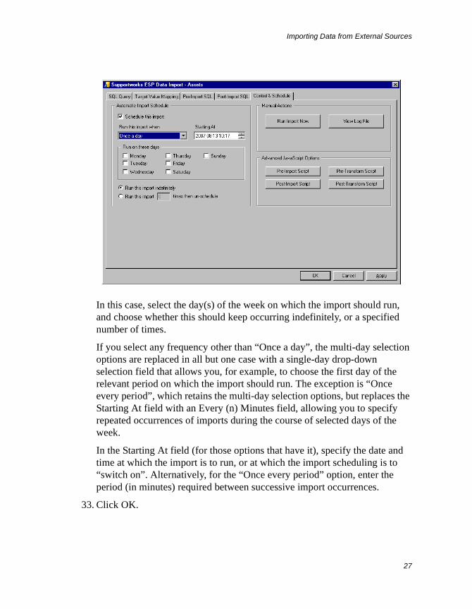
31. If you wish to schedule the import, first enable the “Schedule this import” option.
32. Specify when, or how often, the import is to run by selecting the relevant item from the “Run this import when” field’s drop-down list. If you select “Once a day”, some additional options are immediately displayed:
Importing Data from External Sources
27
In this case, select the day(s) of the week on which the import should run, and choose whether this should keep occurring indefinitely, or a specified number of times.
If you select any frequency other than “Once a day”, the multi-day selection options are replaced in all but one case with a single-day drop-down selection field that allows you, for example, to choose the first day of the relevant period on which the import should run. The exception is “Once every period”, which retains the multi-day selection options, but replaces the Starting At field with an Every (n) Minutes field, allowing you to specify repeated occurrences of imports during the course of selected days of the week.
In the Starting At field (for those options that have it), specify the date and time at which the import is to run, or at which the import scheduling is to “switch on”. Alternatively, for the “Once every period” option, enter the period (in minutes) required between successive import occurrences.
33. Click OK.
Importing Data from External Sources
28
To Define a New SQL Import Based On An Existing One
If you wish to define a new SQL import with properties nearly the same as those of an existing one, the quickest way to do this is to first make a copy of the import concerned and then modify the properties that need changing.
You start by selecting the existing SQL import from the Data Import Manager list and clicking Copy. Then, at the displayed prompt, you would enter a suitable name for the new import and click OK. The Data Import dialogue box would be displayed, allowing you to make the necessary changes.
To Manage an Existing SQL Import
Once you have defined an SQL import, you can redisplay the Data Import dialogue box at any time to make changes to the definition. You can also rename or delete an import.
To access the Data Import dialogue box for modification of an import, select the relevant import from the Data Import Manager list and click Properties (or just double-click the entry).
To rename an import, first select it from the list and click Rename. Then, at the displayed prompt, enter the new name and click OK.
To delete an import, select it from the list and click Delete. Click Yes at the confirmation prompt.
LDAP ImportsThe most likely kind of data you might import using LDAP is internal customer data. If your organisation runs ADS, for example, there will almost certainly be a directory of users held on the network that you should be able to access via LDAP.
To Define a New LDAP Import
The procedure for defining a new LDAP import is as follows:
1. With the Data Import Manager running, select the LDAP Imports tab.
Importing Data from External Sources
29
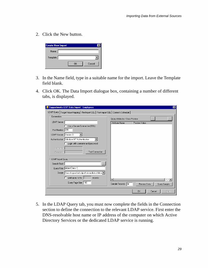
2. Click the New button.
3. In the Name field, type in a suitable name for the import. Leave the Template field blank.
4. Click OK. The Data Import dialogue box, containing a number of different tabs, is displayed.
5. In the LDAP Query tab, you must now complete the fields in the Connection section to define the connection to the relevant LDAP service. First enter the DNS-resolvable host name or IP address of the computer on which Active Directory Services or the dedicated LDAP service is running.
Importing Data from External Sources
30
6. If the LDAP server is enabled for SSL encryption and you want to use it, check the Use a Secure Connection (SSL) option.
7. In the Port Number field, either leave the number at its default value of 389 or, if the LDAP server uses a different TCP port, enter its number.
8. Ensure that the appropriate LDAP version is selected. Note that ADS supports both versions.
9. In the Authentication field, specify the method of authentication to be used in connecting to the LDAP service. You can opt for either Simple Authentication, which logs directly into an LDAP account, or Windows NT Authentication, which provides access via any valid NT account. There is also a third option, which allows automatic negotiation of the authentication method from those currently available. In the case of a scheduled import, you should bear in mind that authentication will take place in the context of the scheduler, and you should ensure that the relevant rights exist.
10. If you check the “Login with username and password” option, you will be able to enter a suitable name and password (in the fields below) for logging into the LDAP service. You can keep this option disabled if you have selected Windows NT Authentication and you will not be scheduling the import, or if the LDAP service is configured not to require logins.
11. Click the Test Connection button to confirm that the connection works. If so, the Data Import Manager will display a message indicating that the test completed successfully. If, on the other hand, you see an error message, you will have to sort out the connection details before continuing any further.
12. With a valid connection defined, you now need to define the LDAP query itself. First specify a search root, which is the path to the container level at which the top-down search should start for suitable data to be imported. Click the browse button next to the Search Root field to display the Browse LDAP Directory and select the required naming context. Then select the required container level from the tree browser and click OK. Notice that the path appears in the Search Root field with the appropriate syntax.
13. If you wish to select specific groups of containers or records at the root level and below, type a suitable filter expression into the Query Filter field. See the documentation supplied with Windows or your LDAP application for details of the syntax you can use. The example filter displayed by default in
Importing Data from External Sources
31
this field selects the entire contents of the root container (but subject to the Scope setting described in the next step).
14. Using the drop-down menu in the Scope field, you can choose how much of the container hierarchy, from the root downwards, should be considered for data importation. Data can be obtained from the root container only, from the root and its immediate “children”, or from the root and all of its “descendants”.
15. If required, you can opt to limit the number of records to be returned by the query. This would normally be useful for testing purposes only.
16. For extra speed, the LDAP query will use paging by default. You can specify the required size of each page in the relevant field. However, some LDAP servers (Lotus Domino, for example) do not support paged mode. In this case, you can set the query page size to 0 (zero), which will turn off paging.
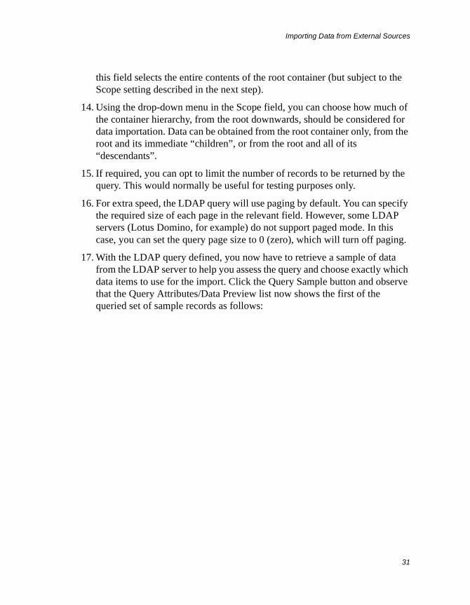
17. With the LDAP query defined, you now have to retrieve a sample of data from the LDAP server to help you assess the query and choose exactly which data items to use for the import. Click the Query Sample button and observe that the Query Attributes/Data Preview list now shows the first of the queried set of sample records as follows:
Importing Data from External Sources
32
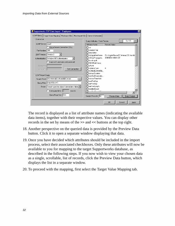
The record is displayed as a list of attribute names (indicating the available data items), together with their respective values. You can display other records in the set by means of the >> and << buttons at the top right.
18. Another perspective on the queried data is provided by the Preview Data button. Click it to open a separate window displaying that data.
19. Once you have decided which attributes should be included in the import process, select their associated checkboxes. Only these attributes will now be available to you for mapping to the target Supportworks database, as described in the following steps. If you now wish to view your chosen data as a single, scrollable, list of records, click the Preview Data button, which displays the list in a separate window.
20. To proceed with the mapping, first select the Target Value Mapping tab.
Importing Data from External Sources
33
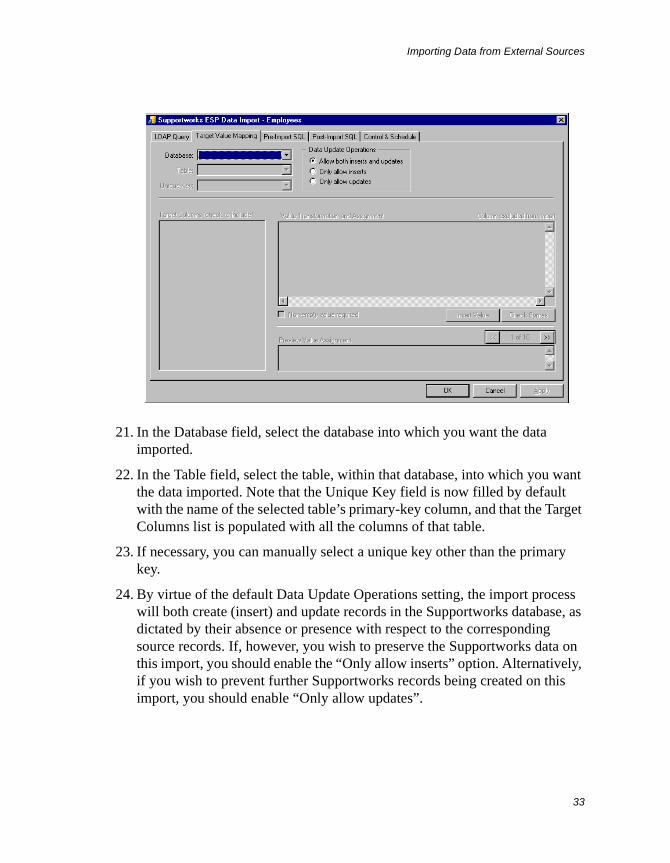
21. In the Database field, select the database into which you want the data imported.
22. In the Table field, select the table, within that database, into which you want the data imported. Note that the Unique Key field is now filled by default with the name of the selected table’s primary-key column, and that the Target Columns list is populated with all the columns of that table.
23. If necessary, you can manually select a unique key other than the primary key.
24. By virtue of the default Data Update Operations setting, the import process will both create (insert) and update records in the Supportworks database, as dictated by their absence or presence with respect to the corresponding source records. If, however, you wish to preserve the Supportworks data on this import, you should enable the “Only allow inserts” option. Alternatively, if you wish to prevent further Supportworks records being created on this import, you should enable “Only allow updates”.
Importing Data from External Sources
34
25. You are now ready to map your previously selected source data attributes to columns of your selected target table. First select the checkboxes associated with your proposed target columns.
26. Highlight one of the selected target columns and click anywhere in the Value Transformation and Assignment field.
27. For a simple mapping, click the Insert Value button and, from the menu that pops up, select the LDAP data attribute that you want mapped to the target column you have highlighted. Notice that the chosen attribute appears in the field in the form ldap.<attribute>.
For more complex mappings, you would have to manually type the required expression into the Value Transformation and Assignment field. See the section entitled Advanced Import Techniques on page 56 to find out what is possible here using JavaScript.
28. If you want the import process to skip each LDAP record where there is no value assigned for the attribute (or for any attribute in the expression), enable the “Non-empty value required” option. This will always be enabled if the target column being mapped is a unique key.
29. If you have entered an expression manually into the Value Transformation and Assignment field, you can confirm correct resolution of the currently highlighted target column’s values by clicking the Check Syntax button. This will display, one at a time in the Preview Value Assignment field, the values for that column as computed by the expression, using the set of sample data you previously queried. You can use the >> and << buttons to show the following and preceding values, respectively.
30. Repeat step 26 to step 29 for each of your proposed target columns.
31. Click Apply.
32. Having completed the mapping, you can now run or schedule the import. First select the Control & Schedule tab.
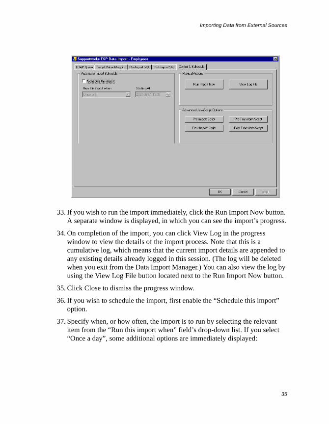
Importing Data from External Sources
35
33. If you wish to run the import immediately, click the Run Import Now button. A separate window is displayed, in which you can see the import’s progress.
34. On completion of the import, you can click View Log in the progress window to view the details of the import process. Note that this is a cumulative log, which means that the current import details are appended to any existing details already logged in this session. (The log will be deleted when you exit from the Data Import Manager.) You can also view the log by using the View Log File button located next to the Run Import Now button.
35. Click Close to dismiss the progress window.
36. If you wish to schedule the import, first enable the “Schedule this import” option.
37. Specify when, or how often, the import is to run by selecting the relevant item from the “Run this import when” field’s drop-down list. If you select “Once a day”, some additional options are immediately displayed:
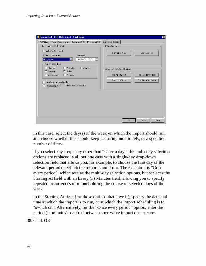
Importing Data from External Sources
36
In this case, select the day(s) of the week on which the import should run, and choose whether this should keep occurring indefinitely, or a specified number of times.
If you select any frequency other than “Once a day”, the multi-day selection options are replaced in all but one case with a single-day drop-down selection field that allows you, for example, to choose the first day of the relevant period on which the import should run. The exception is “Once every period”, which retains the multi-day selection options, but replaces the Starting At field with an Every (n) Minutes field, allowing you to specify repeated occurrences of imports during the course of selected days of the week.
In the Starting At field (for those options that have it), specify the date and time at which the import is to run, or at which the import scheduling is to “switch on”. Alternatively, for the “Once every period” option, enter the period (in minutes) required between successive import occurrences.
38. Click OK.
Importing Data from External Sources
37
To Define a New LDAP Import Based On An Existing One
If you wish to define a new LDAP import with properties nearly the same as those of an existing one, the quickest way to do this is to first make a copy of the import concerned and then modify the properties that need changing.
You start by selecting the existing LDAP import from the Data Import Manager list and clicking Copy. Then, at the displayed prompt, you would enter a suitable name for the new import and click OK. The Data Import dialogue box would be displayed, allowing you to make the necessary changes.
To Manage an Existing LDAP Import
Once you have defined an LDAP import, you can redisplay the Data Import dialogue box at any time to make changes to the definition. You can also rename or delete an import.
To access the Data Import dialogue box for modification of an import, select the relevant import from the Data Import Manager list and click Properties (or just double-click the entry).
To rename an import, first select it from the list and click Rename. Then, at the displayed prompt, enter the new name and click OK.
To delete an import, select it from the list and click Delete. Click Yes at the confirmation prompt.
Text File ImportsYou can import data from any text file that is structured in the same way as a CSV file, although the field limiters do not necessarily have to be commas. If your organisation keeps some data in non-SQL databases, there would normally be facilities available for exporting this to CSV-like files. It would then, in turn, be possible to easily import the data into Supportworks.
To Define a New Text File Import
The procedure for defining a new text file import is as follows:
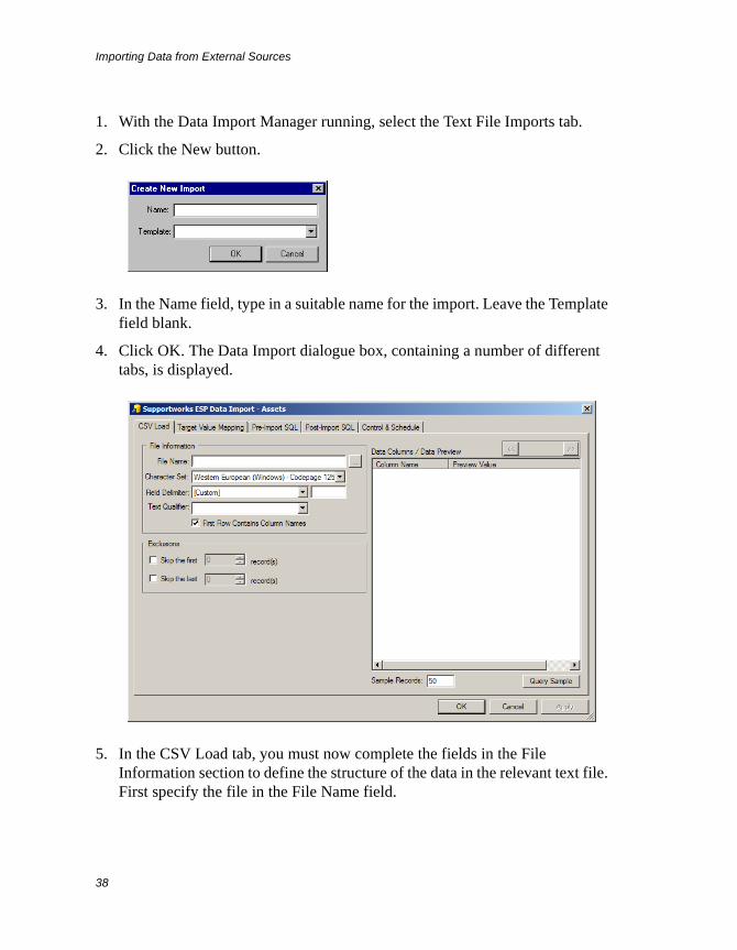
Importing Data from External Sources
38
1. With the Data Import Manager running, select the Text File Imports tab.
2. Click the New button.
3. In the Name field, type in a suitable name for the import. Leave the Template field blank.
4. Click OK. The Data Import dialogue box, containing a number of different tabs, is displayed.
5. In the CSV Load tab, you must now complete the fields in the File Information section to define the structure of the data in the relevant text file. First specify the file in the File Name field.
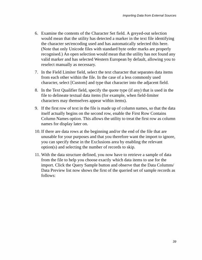
Importing Data from External Sources
39
6. Examine the contents of the Character Set field. A greyed-out selection would mean that the utility has detected a marker in the text file identifying the character set/encoding used and has automatically selected this here. (Note that only Unicode files with standard byte order marks are properly recognised.) An open selection would mean that the utility has not found any valid marker and has selected Western European by default, allowing you to reselect manually as necessary.
7. In the Field Limiter field, select the text character that separates data items from each other within the file. In the case of a less commonly used character, select [Custom] and type that character into the adjacent field.
8. In the Text Qualifier field, specify the quote type (if any) that is used in the file to delineate textual data items (for example, when field-limiter characters may themselves appear within items).
9. If the first row of text in the file is made up of column names, so that the data itself actually begins on the second row, enable the First Row Contains Column Names option. This allows the utility to treat the first row as column names for display later on.
10. If there are data rows at the beginning and/or the end of the file that are unusable for your purposes and that you therefore want the import to ignore, you can specify these in the Exclusions area by enabling the relevant option(s) and selecting the number of records to skip.
11. With the data structure defined, you now have to retrieve a sample of data from the file to help you choose exactly which data items to use for the import. Click the Query Sample button and observe that the Data Columns/Data Preview list now shows the first of the queried set of sample records as follows:
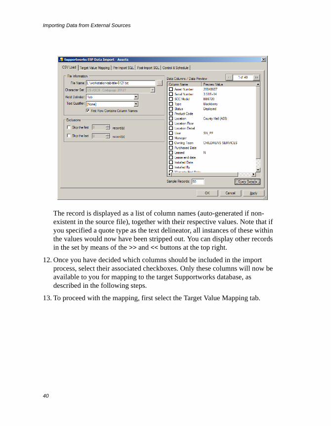
Importing Data from External Sources
40
The record is displayed as a list of column names (auto-generated if non-existent in the source file), together with their respective values. Note that if you specified a quote type as the text delineator, all instances of these within the values would now have been stripped out. You can display other records in the set by means of the >> and << buttons at the top right.
12. Once you have decided which columns should be included in the import process, select their associated checkboxes. Only these columns will now be available to you for mapping to the target Supportworks database, as described in the following steps.
13. To proceed with the mapping, first select the Target Value Mapping tab.
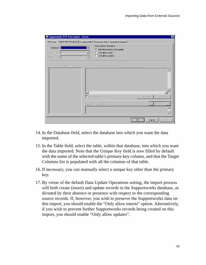
Importing Data from External Sources
41
14. In the Database field, select the database into which you want the data imported.
15. In the Table field, select the table, within that database, into which you want the data imported. Note that the Unique Key field is now filled by default with the name of the selected table’s primary-key column, and that the Target Columns list is populated with all the columns of that table.
16. If necessary, you can manually select a unique key other than the primary key.
17. By virtue of the default Data Update Operations setting, the import process will both create (insert) and update records in the Supportworks database, as dictated by their absence or presence with respect to the corresponding source records. If, however, you wish to preserve the Supportworks data on this import, you should enable the “Only allow inserts” option. Alternatively, if you wish to prevent further Supportworks records being created on this import, you should enable “Only allow updates”.
Importing Data from External Sources
42
18. You are now ready to map your previously selected source columns to columns of your selected target table. First select the checkboxes associated with your proposed target columns.
19. Highlight one of the selected target columns and click anywhere in the Value Transformation and Assignment field.
20. For a simple mapping, click the Insert Value button and, from the menu that pops up, select the source data column that you want mapped to the target column you have highlighted. Notice that the chosen column appears in the field in the form csv.<datacolumn> or csv[“<data column>”], depending on whether or not there are spaces in the source data column’s name.
For more complex mappings, you would have to manually type the required expression into the Value Transformation and Assignment field. See the section entitled Advanced Import Techniques on page 56 to find out what is possible here using JavaScript.
21. If you want the import process to skip each text-file record where there is no value assigned for this column (or for any column in the expression), enable the “Non-empty value required” option. This will always be enabled if the target column being mapped is a unique key.
22. If you have entered an expression manually into the Value Transformation and Assignment field, you can confirm correct resolution of the currently highlighted target column’s values by clicking the Check Syntax button. This will display, one at a time in the Preview Value Assignment field, the values for that column as computed by the expression, using the set of sample data you previously queried. You can use the >> and << buttons to show the following and preceding values, respectively.
23. Repeat step 19 to step 22 for each of your proposed target columns.
24. Click Apply.
25. Having completed the mapping, you can now run or schedule the import. First select the Control & Schedule tab.

Importing Data from External Sources
43
26. If you wish to run the import immediately, click the Run Import Now button. A separate window is displayed, in which you can see the import’s progress.
27. On completion of the import, you can click View Log in the progress window to view the details of the import process. Note that this is a cumulative log, which means that the current import details are appended to any existing details already logged in this session. (The log will be deleted when you exit from the Data Import Manager.) You can also view the log by using the View Log File button located next to the Run Import Now button.
28. Click Close to dismiss the progress window.
29. If you wish to schedule the import, first enable the “Schedule this import” option.
30. Specify when, or how often, the import is to run by selecting the relevant item from the “Run this import when” field’s drop-down list. If you select “Once a day”, some additional options are immediately displayed:

Importing Data from External Sources
44
In this case, select the day(s) of the week on which the import should run, and choose whether this should keep occurring indefinitely, or a specified number of times.
If you select any frequency other than “Once a day”, the multi-day selection options are replaced in all but one case with a single-day drop-down selection field that allows you, for example, to choose the first day of the relevant period on which the import should run. The exception is “Once every period”, which retains the multi-day selection options, but replaces the Starting At field with an Every (n) Minutes field, allowing you to specify repeated occurrences of imports during the course of selected days of the week.
In the Starting At field (for those options that have it), specify the date and time at which the import is to run, or at which the import scheduling is to “switch on”. Alternatively, for the “Once every period” option, enter the period (in minutes) required between successive import occurrences.
31. Click OK.
Importing Data from External Sources
45
To Define a New Text File Import Based On An Existing One
If you wish to define a new text file import with properties nearly the same as those of an existing one, the quickest way to do this is to first make a copy of the import concerned and then modify the properties that need changing.
You start by selecting the existing text file import from the Data Import Manager list and clicking Copy. Then, at the displayed prompt, you would enter a suitable name for the new import and click OK. The Data Import dialogue box would be displayed, allowing you to make the necessary changes.
To Manage an Existing Text File Import
Once you have defined a text file import, you can redisplay the Data Import dialogue box at any time to make changes to the definition. You can also rename or delete an import.
To access the Data Import dialogue box for modification of an import, select the relevant import from the Data Import Manager list and click Properties (or just double-click the entry).
To rename an import, first select it from the list and click Rename. Then, at the displayed prompt, enter the new name and click OK.
To delete an import, select it from the list and click Delete. Click Yes at the confirmation prompt.
Excel ImportsYou can import data from a worksheet of a Microsoft Excel workbook or template file that has any of the following extensions:
.xls, .xlw, .xlt, .xlsx, .xlsm, .xltx, .xltm, .xlax, .xlam, .xltb, .xlab
To Define a New Excel File Import
The procedure for defining a new Excel file import is as follows:
1. With the Data Import Manager running, select the Excel Imports tab.
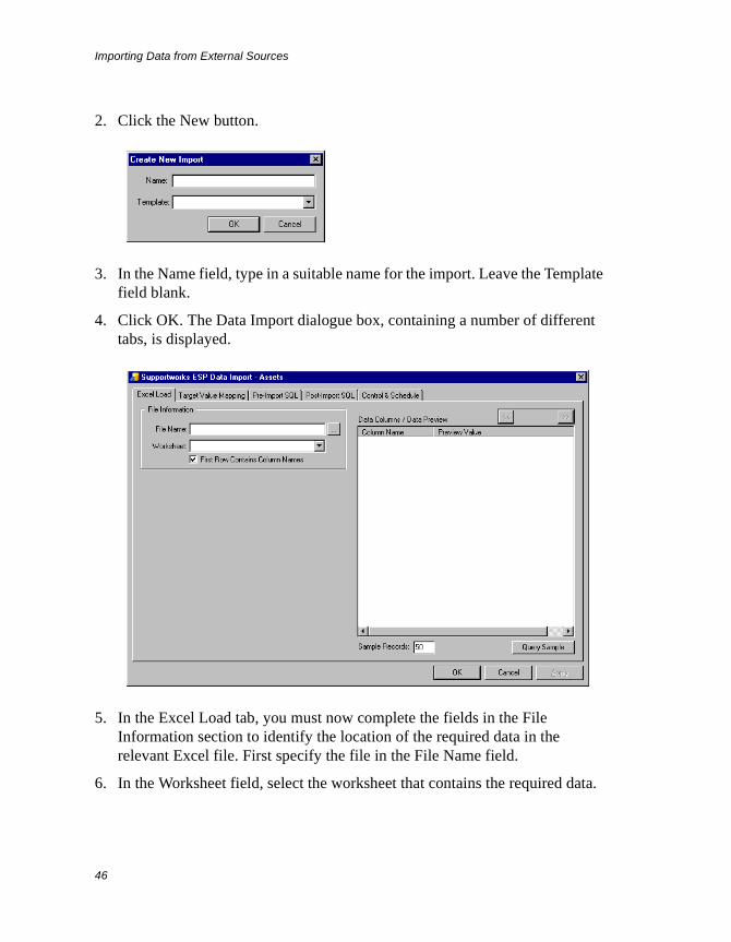
Importing Data from External Sources
46
2. Click the New button.
3. In the Name field, type in a suitable name for the import. Leave the Template field blank.
4. Click OK. The Data Import dialogue box, containing a number of different tabs, is displayed.
5. In the Excel Load tab, you must now complete the fields in the File Information section to identify the location of the required data in the relevant Excel file. First specify the file in the File Name field.
6. In the Worksheet field, select the worksheet that contains the required data.
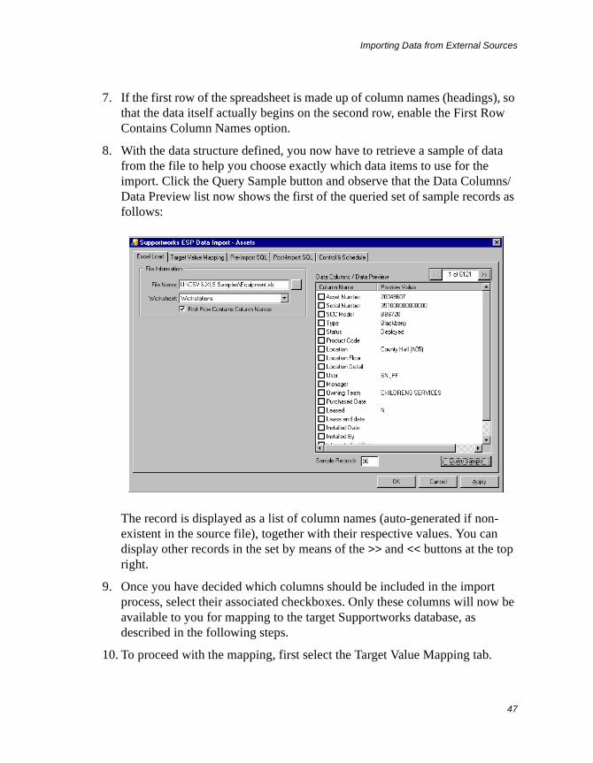
Importing Data from External Sources
47
7. If the first row of the spreadsheet is made up of column names (headings), so that the data itself actually begins on the second row, enable the First Row Contains Column Names option.
8. With the data structure defined, you now have to retrieve a sample of data from the file to help you choose exactly which data items to use for the import. Click the Query Sample button and observe that the Data Columns/Data Preview list now shows the first of the queried set of sample records as follows:
The record is displayed as a list of column names (auto-generated if non-existent in the source file), together with their respective values. You can display other records in the set by means of the >> and << buttons at the top right.
9. Once you have decided which columns should be included in the import process, select their associated checkboxes. Only these columns will now be available to you for mapping to the target Supportworks database, as described in the following steps.
10. To proceed with the mapping, first select the Target Value Mapping tab.
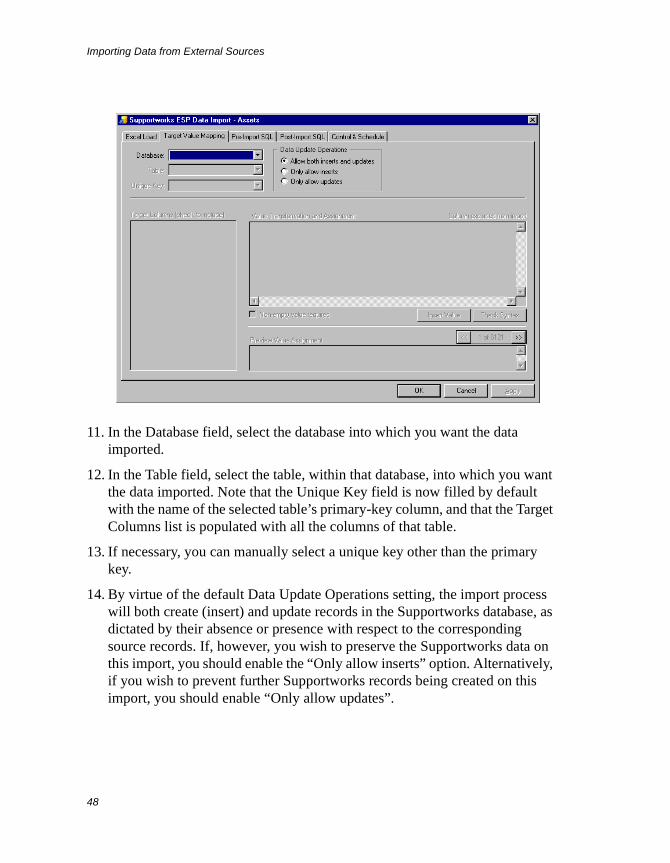
Importing Data from External Sources
48
11. In the Database field, select the database into which you want the data imported.
12. In the Table field, select the table, within that database, into which you want the data imported. Note that the Unique Key field is now filled by default with the name of the selected table’s primary-key column, and that the Target Columns list is populated with all the columns of that table.
13. If necessary, you can manually select a unique key other than the primary key.
14. By virtue of the default Data Update Operations setting, the import process will both create (insert) and update records in the Supportworks database, as dictated by their absence or presence with respect to the corresponding source records. If, however, you wish to preserve the Supportworks data on this import, you should enable the “Only allow inserts” option. Alternatively, if you wish to prevent further Supportworks records being created on this import, you should enable “Only allow updates”.

Importing Data from External Sources
49
15. You are now ready to map your previously selected source columns to columns of your selected target table. First select the checkboxes associated with your proposed target columns.
16. Highlight one of the selected target columns and click anywhere in the Value Transformation and Assignment field.
17. For a simple mapping, click the Insert Value button and, from the menu that pops up, select the source data column that you want mapped to the target column you have highlighted. Notice that the chosen column appears in the field in the form xls.<datacolumn> or xls[“<data column>”], depending on whether or not there are spaces in the source data column’s name.
For more complex mappings, you would have to manually type the required expression into the Value Transformation and Assignment field. See the section entitled Advanced Import Techniques on page 56 to find out what is possible here using JavaScript.
18. If you want the import process to skip each Excel-file record where there is no value assigned for this column (or for any column in the expression), enable the “Non-empty value required” option. This will always be enabled if the target column being mapped is a unique key.
19. If you have entered an expression manually into the Value Transformation and Assignment field, you can confirm correct resolution of the currently highlighted target column’s values by clicking the Check Syntax button. This will display, one at a time in the Preview Value Assignment field, the values for that column as computed by the expression, using the set of sample data you previously queried. You can use the >> and << buttons to show the following and preceding values, respectively.
20. Repeat step 16 to step 19 for each of your proposed target columns.
21. Click Apply.
22. Having completed the mapping, you can now run or schedule the import. First select the Control & Schedule tab.

Importing Data from External Sources
50
23. If you wish to run the import immediately, click the Run Import Now button. A separate window is displayed, in which you can see the import’s progress.
24. On completion of the import, you can click View Log in the progress window to view the details of the import process. Note that this is a cumulative log, which means that the current import details are appended to any existing details already logged in this session. (The log will be deleted when you exit from the Data Import Manager.) You can also view the log by using the View Log File button located next to the Run Import Now button.
25. Click Close to dismiss the progress window.
26. If you wish to schedule the import, first enable the “Schedule this import” option.
27. Specify when, or how often, the import is to run by selecting the relevant item from the “Run this import when” field’s drop-down list. If you select “Once a day”, some additional options are immediately displayed:
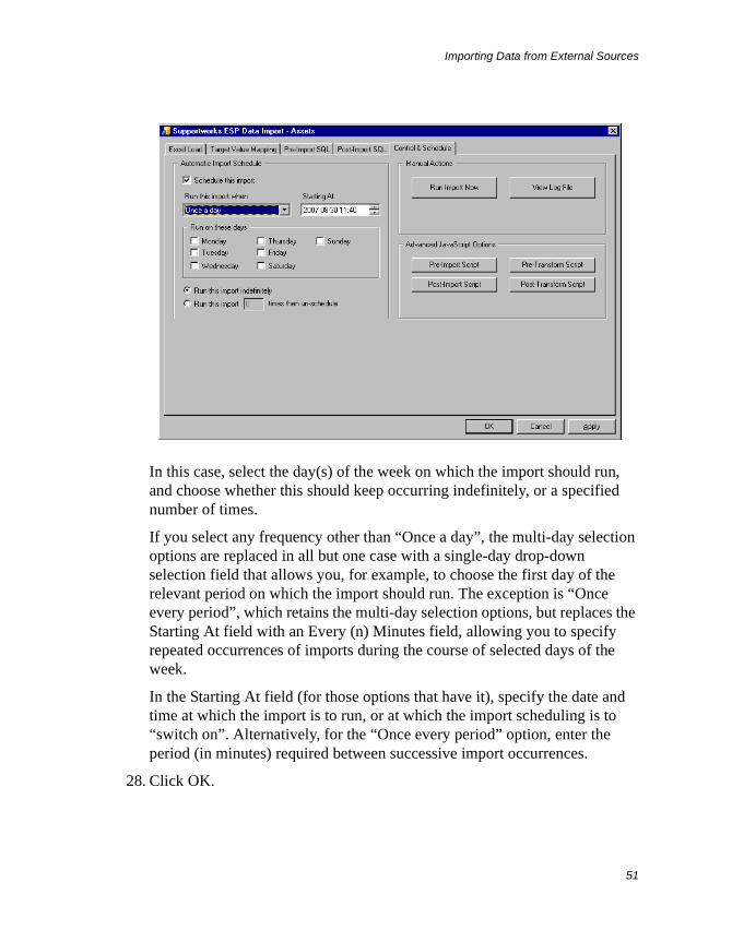
Importing Data from External Sources
51
In this case, select the day(s) of the week on which the import should run, and choose whether this should keep occurring indefinitely, or a specified number of times.
If you select any frequency other than “Once a day”, the multi-day selection options are replaced in all but one case with a single-day drop-down selection field that allows you, for example, to choose the first day of the relevant period on which the import should run. The exception is “Once every period”, which retains the multi-day selection options, but replaces the Starting At field with an Every (n) Minutes field, allowing you to specify repeated occurrences of imports during the course of selected days of the week.
In the Starting At field (for those options that have it), specify the date and time at which the import is to run, or at which the import scheduling is to “switch on”. Alternatively, for the “Once every period” option, enter the period (in minutes) required between successive import occurrences.
28. Click OK.
Importing Data from External Sources
52
To Define a New Excel File Import Based On An Existing One
If you wish to define a new Excel file import with properties nearly the same as those of an existing one, the quickest way to do this is to first make a copy of the import concerned and then modify the properties that need changing.
You start by selecting the existing Excel file import from the Data Import Manager list and clicking Copy. Then, at the displayed prompt, you would enter a suitable name for the new import and click OK. The Data Import dialogue box would be displayed, allowing you to make the necessary changes.
To Manage an Existing Excel File Import
Once you have defined an Excel file import, you can redisplay the Data Import dialogue box at any time to make changes to the definition. You can also rename or delete an import.
To access the Data Import dialogue box for modification of an import, select the relevant import from the Data Import Manager list and click Properties (or just double-click the entry).
To rename an import, first select it from the list and click Rename. Then, at the displayed prompt, enter the new name and click OK.
To delete an import, select it from the list and click Delete. Click Yes at the confirmation prompt.
Other ImportsThe final tab of the Data Import Manager is reserved for ad-hoc importation of Supportworks-specific data. Currently, only call-profile data imports are supported. With such an import, you can populate either the problem/request profile tables or the resolution profile tables with data you previously entered into a Microsoft Excel worksheet.
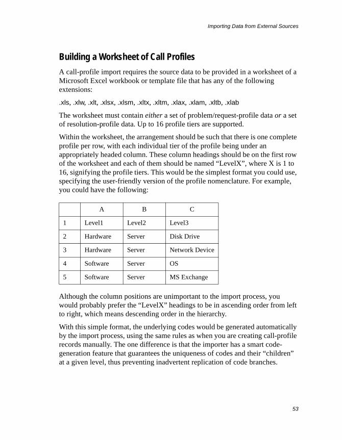
Importing Data from External Sources
53
Building a Worksheet of Call Profiles
A call-profile import requires the source data to be provided in a worksheet of a Microsoft Excel workbook or template file that has any of the following extensions:
.xls, .xlw, .xlt, .xlsx, .xlsm, .xltx, .xltm, .xlax, .xlam, .xltb, .xlab
The worksheet must contain either a set of problem/request-profile data or a set of resolution-profile data. Up to 16 profile tiers are supported.
Within the worksheet, the arrangement should be such that there is one complete profile per row, with each individual tier of the profile being under an appropriately headed column. These column headings should be on the first row of the worksheet and each of them should be named “LevelX”, where X is 1 to 16, signifying the profile tiers. This would be the simplest format you could use, specifying the user-friendly version of the profile nomenclature. For example, you could have the following:
Although the column positions are unimportant to the import process, you would probably prefer the “LevelX” headings to be in ascending order from left to right, which means descending order in the hierarchy.
With this simple format, the underlying codes would be generated automatically by the import process, using the same rules as when you are creating call-profile records manually. The one difference is that the importer has a smart code-generation feature that guarantees the uniqueness of codes and their “children” at a given level, thus preventing inadvertent replication of code branches.
A B C
1 Level1 Level2 Level3
2 Hardware Server Disk Drive
3 Hardware Server Network Device
4 Software Server OS
5 Software Server MS Exchange
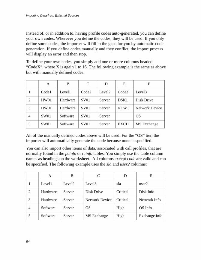
Importing Data from External Sources
54
Instead of, or in addition to, having profile codes auto-generated, you can define your own codes. Wherever you define the codes, they will be used. If you only define some codes, the importer will fill in the gaps for you by automatic code generation. If you define codes manually and they conflict, the import process will display an error and then stop.
To define your own codes, you simply add one or more columns headed “CodeX”, where X is again 1 to 16. The following example is the same as above but with manually defined codes:
All of the manually defined codes above will be used. For the “OS” tier, the importer will automatically generate the code because none is specified.
You can also import other items of data, associated with call profiles, that are normally found in the pcinfo or rcinfo tables. You simply use the table column names as headings on the worksheet. All columns except code are valid and can be specified. The following example uses the sla and user2 columns:
A B C D E F
1 Code1 Level1 Code2 Level2 Code3 Level3
2 HW01 Hardware SV01 Server DSK1 Disk Drive
3 HW01 Hardware SV01 Server NTW1 Network Device
4 SW01 Software SV01 Server OS
5 SW01 Software SV01 Server EXCH MS Exchange
A B C D E
1 Level1 Level2 Level3 sla user2
2 Hardware Server Disk Drive Critical Disk Info
3 Hardware Server Network Device Critical Network Info
4 Software Server OS High OS Info
5 Software Server MS Exchange High Exchange Info
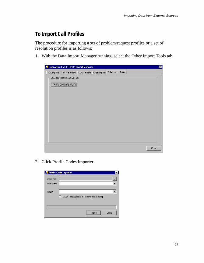
Importing Data from External Sources
55
To Import Call Profiles
The procedure for importing a set of problem/request profiles or a set of resolution profiles is as follows:
1. With the Data Import Manager running, select the Other Import Tools tab.
2. Click Profile Codes Importer.
Importing Data from External Sources
56
3. Click the browse button next to the Import File field and select the Excel file that contains the call profiles to be imported. Click Open.
4. If there is more than one worksheet within the Excel file, select, in the Worksheet field, the one that contains the required call profiles.
5. In the Target field, specify whether the call profiles to be imported are problem/request profiles or resolution profiles.
6. If you want all currently existing call-profile records of the target type deleted from the Supportworks database before importation proceeds, ensure that the Clean Tables option is enabled.
7. Click Import.
The call profiles are imported.
Advanced Import TechniquesIn the real world, it is frequently the case that, when you want to import data, you find that there is no one-to-one match between certain source and target data items, and you would therefore have to “transform” one to fit the other. Also, it is always possible that the mapping needs to be qualified in some way, or that some kind of causative linking needs to be maintained between the source and target. In such complex (but realistic) cases, you will have to supplement the basic procedures given in the above sections with some of the techniques described here.
Each of these techniques will require expertise in either SQL or JavaScript, depending on what exactly you need to do.
Programmed Mapping Using JavaScript
In all four sets of import instructions given above, it was mentioned that the Value Transformation and Assignment field in the Target Value Mapping tab is editable, and you will no doubt have noticed the “dot” notation used in that field to assign the source data. This auto-generated assignment is actually a simple JavaScript expression that you could replace with a more complex one, or perhaps with just a constant value, by entering the script directly in the field.
Importing Data from External Sources
57
For example, the Supportworks Customer table has a person’s first name and last name in two separate columns, but it could be that the only corresponding data item available for your LDAP query is the “displayName” attribute, which has the person’s first and last name in a single field, separated by a space. In this case, for correct mapping, the process would need to split the source string and assign the left and right of the split string to two separate columns. Conversely, you may, in other instances, need to join two values to put into a single column.
To achieve a split as just described, you would first have to highlight the firstname target column and type the following expression into the Value Transformation and Assignment field:
ldap.displayName.split(“ ”)[0]
Then, with the surname column highlighted, you would enter the following expression:
ldap.displayName.split(“ ”)[1]
You can see that the original name string is split into two, and the resulting portions are made available within two distinct elements of an array. This is no longer a simple mapping but an actual value transformation. In fact, JavaScript will allow you to incorporate even more complex transformations in your imports, for example, by using regular expressions.
Furthermore, you are able to put any kind of JavaScript-coded logic around these expressions. Here, for example, is some code that uses a test to decide which one of two source data items is to apply for the mapping:
if(ldap.distinguishedName == “”) ldap.dnelse ldap.distinguishedName
What this is doing is checking to see if the ldap.distinguishedName attribute is empty and, if so, returning the value of the ldap.dn attribute instead.
Pre- and Post-Import SQL Action on the Target Database
For any given import, you can have an SQL statement submitted to the Supportworks database both before and after the actual data importation. These statements would be used for initialising and finalising target-related conditions
Importing Data from External Sources
58
for the import. You would enter such statements in the Pre-Import SQL edit tab and the Post-Import SQL edit tab, respectively, of the Data Import dialogue box.
For example, suppose you want to keep records in the Customer table (userdb) synchronised with those in the LDAP directory by marking the former as inactive if the customers concerned are no longer in the LDAP directory. You could firstly create a control column called imp_control and a status column called state in the userdb table. You would then enter the following statement in the Pre-Import SQL tab:
UPDATE userdb SET imp_control = 1;
This would set the control value to 1 for every record in the table. In the import mapping, you would set this column to 0 for every record processed (by entering simply the constant value 0 in the Value Transformation and Assignment field of the Target Value Mapping tab). So far, this would mean that whenever the import is run, on completion of the actual data importation, all records in the userdb table that had not been imported from the LDAP directory would still have 1 in the imp_control column. We would therefore enter the following statement in the Post-Import SQL tab to mark these records as inactive:
UPDATE userdb SET state = 'Inactive' WHERE imp_control = 1;
The above is quite a simple example, but it does demonstrate the concept of import initialisation and finalisation using SQL.
Manipulating an Import and Its Mapping with JavaScript
The Data Import Manager provides programming spaces in which you can enter JavaScript code to introduce extra functionality at strategic points within the import process. In the Control & Schedule tab, you will find four buttons relating to advanced JavaScript options. Clicking one of these opens a script window that allows you to write JavaScript code to manipulate the start or end of either the import as a whole or each of its value-transformation operations. Note that the editor in the JavaScript window supports syntax highlighting, code outlining, line numbering and intelligent sensing.
Pre-Import JavaScript
This script, written in the window accessed via the Pre-Import Script button, will be invoked once at the start of the import. If you wanted the Data Import
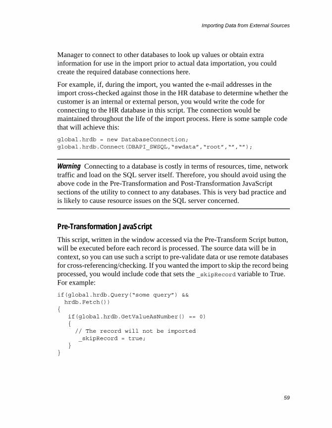
Importing Data from External Sources
59
Manager to connect to other databases to look up values or obtain extra information for use in the import prior to actual data importation, you could create the required database connections here.
For example, if, during the import, you wanted the e-mail addresses in the import cross-checked against those in the HR database to determine whether the customer is an internal or external person, you would write the code for connecting to the HR database in this script. The connection would be maintained throughout the life of the import process. Here is some sample code that will achieve this:
global.hrdb = new DatabaseConnection;global.hrdb.Connect(DBAPI_SWSQL,“swdata”,“root”,“”,“”);
Warning Connecting to a database is costly in terms of resources, time, network traffic and load on the SQL server itself. Therefore, you should avoid using the above code in the Pre-Transformation and Post-Transformation JavaScript sections of the utility to connect to any databases. This is very bad practice and is likely to cause resource issues on the SQL server concerned.
Pre-Transformation JavaScript
This script, written in the window accessed via the Pre-Transform Script button, will be executed before each record is processed. The source data will be in context, so you can use such a script to pre-validate data or use remote databases for cross-referencing/checking. If you wanted the import to skip the record being processed, you would include code that sets the _skipRecord variable to True. For example:
if(global.hrdb.Query(“some query”) && hrdb.Fetch()){ if(global.hrdb.GetValueAsNumber() == 0) { // The record will not be imported _skipRecord = true; }}
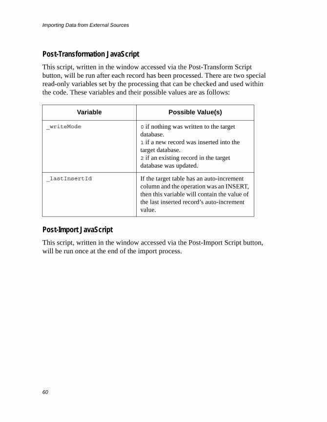
Importing Data from External Sources
60
Post-Transformation JavaScript
This script, written in the window accessed via the Post-Transform Script button, will be run after each record has been processed. There are two special read-only variables set by the processing that can be checked and used within the code. These variables and their possible values are as follows:
Post-Import JavaScript
This script, written in the window accessed via the Post-Import Script button, will be run once at the end of the import process.
Variable Possible Value(s)
_writeMode 0 if nothing was written to the target database.1 if a new record was inserted into the target database.2 if an existing record in the target database was updated.
_lastInsertId If the target table has an auto-increment column and the operation was an INSERT, then this variable will contain the value of the last inserted record’s auto-increment value.
Administrative Entities
61
Administrative Entities
Administrative entities are named sets of operational definitions that are selectable by name on call forms. Unlike “managed entities”, administrative entities apply to the Supportworks platform as a whole, and their user interfaces are therefore not customisable on a per-application basis. The three basic types of administrative entity are as follows:
• Service Level Agreements (SLAs)
• Call profiles
• Workflow templates
The characteristics of each SLA, call profile or workflow template are stored in a record in the appropriate table. Before your Supportworks system goes live, you will have to ensure that all the required records exist and contain the correct data. Equally, if your system has been live for a while, you may wish to make changes to some of this data. In either case, you will be using a relevant management facility to achieve your goal.
This chapter describes the administrative entities and the facilities available for managing them.
Service Level AgreementsIn this section, you are first introduced to the idea of SLAs, with particular mention of how they are implemented in Supportworks, and also to the notion of third-party SLAs. You are then shown how to perform each of the available SLA management tasks in turn.
Introduction to Service Level Agreements
A Service Level Agreement (SLA) is the specification of a particular level of customer support that your organisation offers, either internally or externally (or both). For each agreement, the level of service given is defined in terms of maximum expected response and fix times, escalation trigger times, and the
Administrative Entities
62
periods during which support staff will be available to handle calls. Supportworks allows you to fully define all of these parameters (in records within the SLA table) for as many different SLAs as your organisation supports. If your organisation offers, for example, a number of different levels of service contract for its external customers, each of these would easily map to a suitably defined SLA.
SLAs ensure that, wherever possible, every support issue is handled within the designated time. SLAs are one of the key means of monitoring performance at your helpdesk. At the very least, they are able to provide a mechanism by which automatic reminders are sent to analysts. Even if your helpdesk is not contracted to meet SLAs, it is nevertheless beneficial to try and resolve support issues within a reasonable time and to find out which individuals are consistently failing to do this. SLAs are also a useful means of establishing which areas of support are the most time-consuming for analysts, and which analysts would benefit from further specific training.
The SLA functionality provided by Supportworks is based on response and fix timers that allow the system to monitor the progress of calls against the target timescales for initially responding to them and ultimately resolving them. For a given call, both timers are started when the analyst logs the call. They would be temporarily suspended during any period defined as being out of business hours, and while the call is on hold. The response timer is not finally stopped until an analyst action interpreted as an initial response occurs. The fix timer is not stopped until the call is understood to be resolved or closed. When a timer stops, the elapsed time to that point is recorded. This measured time would, of course, exclude all suspension periods, just as predefined SLA target times would always exclude periods outside working hours and periods of forced inactivity caused by factors outside the control of the support team.
Intrinsic to any SLA are automated escalations and associated alerts. Escalation means that, as a logged call approaches (or runs beyond) a designated response or fix time, more people can become aware of the increasing urgency of the problem. Such awareness would arise from escalation triggers defined in the SLA. These are scheduled events that may change the status of a call, generating one or more preconfigured actions (mostly reminders, alerts and notifications).
Administrative Entities
63
It is possible to configure two kinds of escalation trigger, one effective at a given time prior to the expiry of the response or fix time, and the other recurring at set intervals after its expiry.
You can assign one of four degrees of urgency to an escalation trigger, depending on how far along the call life-cycle it is to be scheduled:
• Non-escalation. This will merely send a pop-up reminder to the call owner, without changing the call status or recording the event in the call diary.
• Escalation to the call owner. This will send a pop-up alert to the call owner, will change the call status to Escalated (O), and will record the event in the call diary.
• Escalation to the call owner’s group. This will send a pop-up alert to all members of the call owner’s group, will change the call status to Escalated (G), and will record the event in the call diary.
• Escalation to all support analysts. This will send a pop-up alert to all members of your organisation’s support team, will change the call status to Escalated (A), and will record the event in the call diary.
In addition, you can specify, for each escalation trigger, which (if any) of the following actions the system must perform at the scheduled time:
• Send a notification message via the Messenger to a selected individual or group within the support team. Typically, this may be the helpdesk manager or supervisor.
• Send a notifying e-mail message to a selected person in any of the address books. This may be someone who is not normally logged into the helpdesk.
• Transfer ownership of the call to a selected member or group within the support team.
Analysts need not rely solely on specific reminders, alerts and notifications to keep themselves aware of the current state of urgency of a call. They should also be able to see the situation at a glance by looking at either the Condition or the Escalation column of any of their call lists in the Helpdesk view. To that effect, you can optionally assign one of up to 24 possible call conditions or, alternatively, one of 36 possible escalation levels, to each escalation trigger. These will then appear as colour-coded indicators against calls listed in a call-list tab, each representing the degree of urgency appropriate to the level of escalation that applies at any given time for the call concerned. You have a
Administrative Entities
64
choice of up to four different geometric shapes to use as call-condition indicators, each in one of up to six colours. In the case of the escalation-level indicators, you have a choice of six arrows at incrementally increasing sizes, each again in one of six colours.
The main functional difference between these two schemes is that, with call conditions, it is possible for an analyst to set an initial state on a per-call basis and (if appropriate) to subsequently keep changing the state independently of the escalation level. No such manual functionality is available for the arrow-style escalation-level indicators. By virtue of these manual facilities, you can use call conditions to indicate the priorities of individual calls, whether changing or static over the lifetime of the call. At the same time, you could use the arrow scheme to track escalation levels.
Once you have defined all the SLAs offered by your organisation, you will be able to assign any of them to customers, assets, charge centres and/or call profiles. This is how, for example, each customer record would be associated with the type of service contract they have purchased. Furthermore, if any of the contracts contain clauses that single out certain items of equipment for special treatment in relation to level of support, any SLAs created to cover such levels could, at the same time, be associated with the respective items of equipment. Similarly, if you want certain kinds of problem to receive higher-priority support, you would assign suitable SLAs to the relevant problem profiles. Yet another example of SLA assignment, in the case (especially) of internal support, could arise when there is a requirement to charge departments differently to reflect their varying support needs. In such circumstances, you would assign different SLAs to the respective charge centres.
Whenever a call is logged, the analyst can choose either the basis on which the SLA is to be applied for that call, or the specific SLA itself. Typically, the default would be to use the customer-based SLA.
To indicate one possible way of managing SLAs in a support environment, a worked example is provided in the example below.
Example
DO IT offer two different types of support service, corresponding to two different sets of SLAs. One set is for external, FAST customers who pay for varying levels of software support, and the other is for internal DO IT staff who
Administrative Entities
65
are provided with multiple tiers of hardware support. As DO IT maintain a policy of cross-departmental charging, it is essential that the respective SLAs are adhered to wherever possible. It is also important for the two types of SLA to be easily distinguishable.
Consequently, it has been decided that the FAST-customer SLAs will be named after the technical support options on offer from DO IT: Gold, Silver and Bronze Support Premiums. To make internal SLAs apparent, DO IT have decided to name them High, Medium and Low. DO IT do not hold any SLAs against assets, which means that it will not be necessary to assign SLAs to asset records.
Additionally, it is essential that the escalations and alerts within each SLA reflect the practices in place within the DO IT support operation. Therefore, it has been decided that all SLAs will follow the same pattern of escalation: four trigger actions before the response time is met, and a similar four actions (with different timings) before the fix time is met. During both pre-response and pre-fix phases, the first action against a call will be a simple reminder to the call owner, and this will not be tracked in the call diary. The second action will be a recorded escalation of the call to the call owner. The third will be an escalation of the call to the owner’s support group, and the fourth will be a transferral of call ownership to the helpdesk administrator. Although other escalations and alerts are available, DO IT have chosen to specify the same set of actions against every SLA, applying this to both the response and fix triggers.
As far as support periods are concerned, it is possible to specify different hours of business for different SLAs, perhaps depending on the geographical location of the customer or asset that is being supported. However, this is not a consideration for DO IT, as they keep to one standard set of business hours during which they provide support, irrespective of the potential origin of any calls they may receive.
Third Party SLAs
Normally, a Service Level Agreement would simply be between your support team and the customer. However, if you are outsourcing some of the more specialist aspects of your support function, such as the maintenance of certain hardware, you may also need to negotiate and define Service Level Agreements between yourselves and the third parties concerned.
Administrative Entities
66
In Supportworks, you manage third-party SLAs via the Support Team tree browser. Once you have enabled the feature for a given data dictionary (as described in the relevant chapter of the System Customisation Guide), a new root category called Third Party Suppliers appears in the Helpdesk view’s tree browser. Under this category, you can create entries for all of the outsourced support suppliers with which you have SLAs. Then, for each third-party supplier, you can create sub-entries in which you would define the SLAs and reference the written contracts that you have with the organisation. Much of the dialogue used for defining these third-party SLAs is identical to that used for defining the underlying call SLAs. Both kinds of SLA data are stored in the same table (whereas the data on third-party suppliers is stored in one of the Support Analyst tables).
During the life-cycle of a call, the relevant third-party SLA would be invoked by an analyst temporarily assigning the call to that SLA. Typically, such an assignment would place the call on hold automatically, although you can opt to give the analyst control over whether or not the call should go on hold in any particular instance. In relation to response and fix times, escalations and notifications, the system will treat the third-party SLA as simply an additional SLA, totally independent of the call SLA that would also be in force for the same call. Ultimately, the call would be manually re-assigned to an analyst. This would be the point that the system recognises as the third-party fix time, and would also be the point at which the call comes off hold (unless it has already done so by manual command or by virtue of reaching the automatic off-hold point).
Adding a New SLA
To create a new SLA record, follow the instructions given here:
1. From the Administration menu, select Manage Service Level Agreements to view the Manage Service Level Agreements dialogue box.
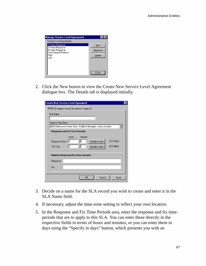
Administrative Entities
67
2. Click the New button to view the Create New Service Level Agreement dialogue box. The Details tab is displayed initially.
3. Decide on a name for the SLA record you wish to create and enter it in the SLA Name field.
4. If necessary, adjust the time-zone setting to reflect your own location.
5. In the Response and Fix Time Periods area, enter the response and fix time-periods that are to apply to this SLA. You can enter these directly in the respective fields in terms of hours and minutes, or you can enter them in days using the “Specify in days” button, which presents you with an
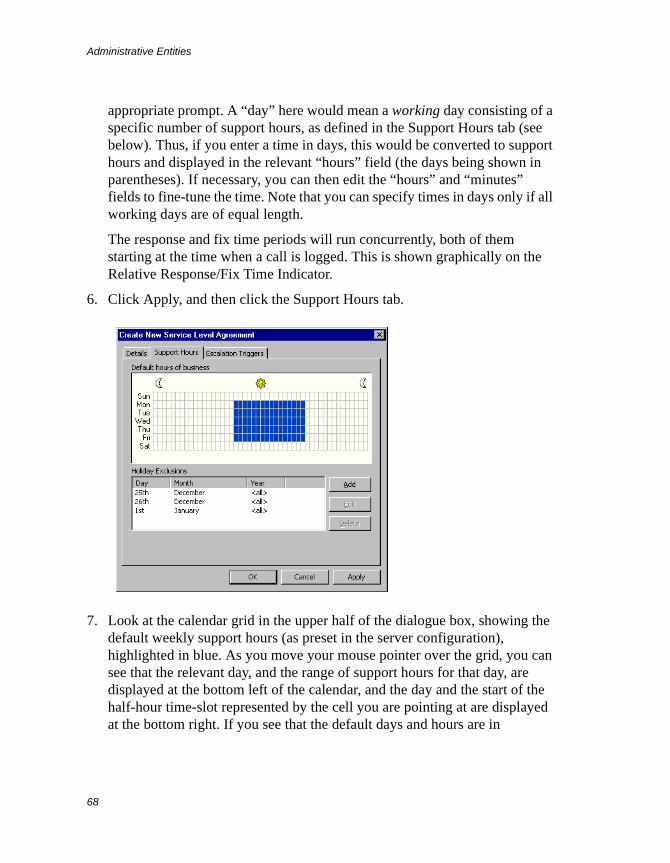
Administrative Entities
68
appropriate prompt. A “day” here would mean a working day consisting of a specific number of support hours, as defined in the Support Hours tab (see below). Thus, if you enter a time in days, this would be converted to support hours and displayed in the relevant “hours” field (the days being shown in parentheses). If necessary, you can then edit the “hours” and “minutes” fields to fine-tune the time. Note that you can specify times in days only if all working days are of equal length.
The response and fix time periods will run concurrently, both of them starting at the time when a call is logged. This is shown graphically on the Relative Response/Fix Time Indicator.
6. Click Apply, and then click the Support Hours tab.
7. Look at the calendar grid in the upper half of the dialogue box, showing the default weekly support hours (as preset in the server configuration), highlighted in blue. As you move your mouse pointer over the grid, you can see that the relevant day, and the range of support hours for that day, are displayed at the bottom left of the calendar, and the day and the start of the half-hour time-slot represented by the cell you are pointing at are displayed at the bottom right. If you see that the default days and hours are in
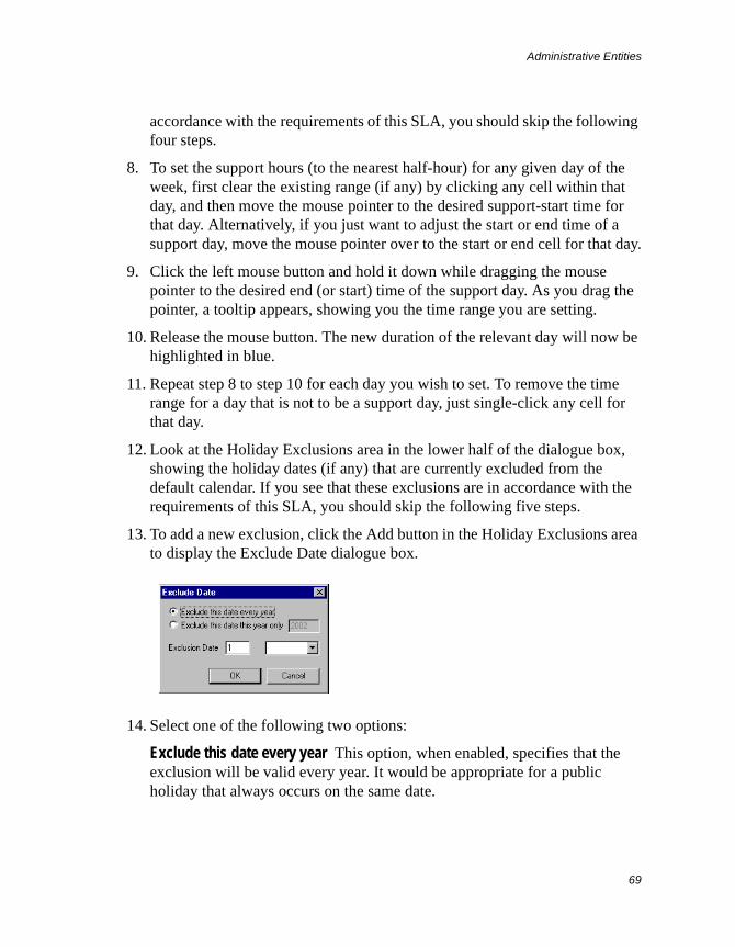
Administrative Entities
69
accordance with the requirements of this SLA, you should skip the following four steps.
8. To set the support hours (to the nearest half-hour) for any given day of the week, first clear the existing range (if any) by clicking any cell within that day, and then move the mouse pointer to the desired support-start time for that day. Alternatively, if you just want to adjust the start or end time of a support day, move the mouse pointer over to the start or end cell for that day.
9. Click the left mouse button and hold it down while dragging the mouse pointer to the desired end (or start) time of the support day. As you drag the pointer, a tooltip appears, showing you the time range you are setting.
10. Release the mouse button. The new duration of the relevant day will now be highlighted in blue.
11. Repeat step 8 to step 10 for each day you wish to set. To remove the time range for a day that is not to be a support day, just single-click any cell for that day.
12. Look at the Holiday Exclusions area in the lower half of the dialogue box, showing the holiday dates (if any) that are currently excluded from the default calendar. If you see that these exclusions are in accordance with the requirements of this SLA, you should skip the following five steps.
13. To add a new exclusion, click the Add button in the Holiday Exclusions area to display the Exclude Date dialogue box.
14. Select one of the following two options:
Exclude this date every year This option, when enabled, specifies that the exclusion will be valid every year. It would be appropriate for a public holiday that always occurs on the same date.
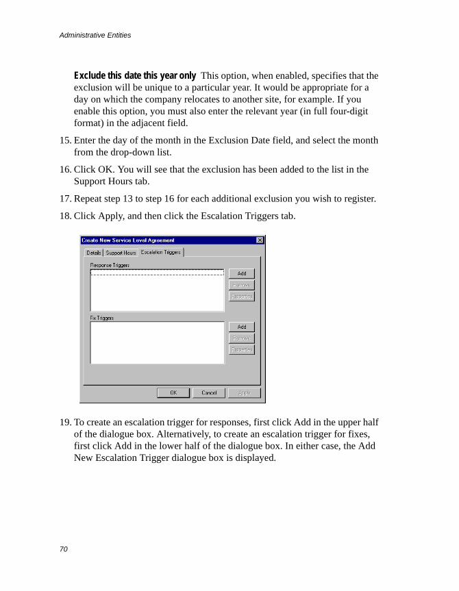
Administrative Entities
70
Exclude this date this year only This option, when enabled, specifies that the exclusion will be unique to a particular year. It would be appropriate for a day on which the company relocates to another site, for example. If you enable this option, you must also enter the relevant year (in full four-digit format) in the adjacent field.
15. Enter the day of the month in the Exclusion Date field, and select the month from the drop-down list.
16. Click OK. You will see that the exclusion has been added to the list in the Support Hours tab.
17. Repeat step 13 to step 16 for each additional exclusion you wish to register.
18. Click Apply, and then click the Escalation Triggers tab.
19. To create an escalation trigger for responses, first click Add in the upper half of the dialogue box. Alternatively, to create an escalation trigger for fixes, first click Add in the lower half of the dialogue box. In either case, the Add New Escalation Trigger dialogue box is displayed.
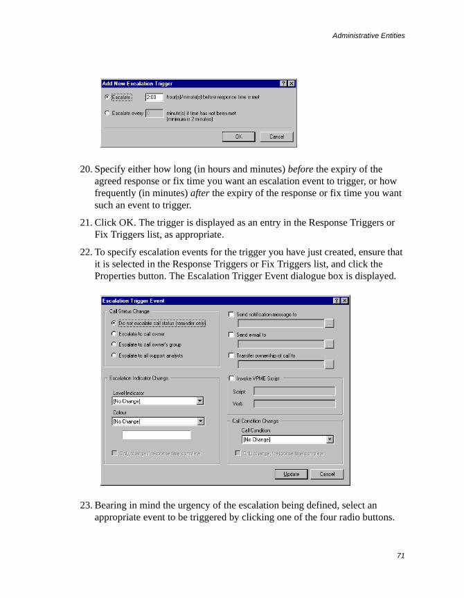
Administrative Entities
71
20. Specify either how long (in hours and minutes) before the expiry of the agreed response or fix time you want an escalation event to trigger, or how frequently (in minutes) after the expiry of the response or fix time you want such an event to trigger.
21. Click OK. The trigger is displayed as an entry in the Response Triggers or Fix Triggers list, as appropriate.
22. To specify escalation events for the trigger you have just created, ensure that it is selected in the Response Triggers or Fix Triggers list, and click the Properties button. The Escalation Trigger Event dialogue box is displayed.
23. Bearing in mind the urgency of the escalation being defined, select an appropriate event to be triggered by clicking one of the four radio buttons.
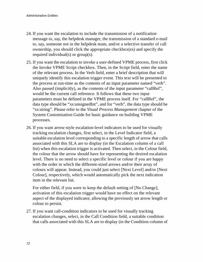
Administrative Entities
72
24. If you want the escalation to include the transmission of a notification message to, say, the helpdesk manager, the transmission of a standard e-mail to, say, someone not in the helpdesk team, and/or a selective transfer of call ownership, you should click the appropriate checkbox(es) and specify the required individual(s) or group(s).
25. If you want the escalation to invoke a user-defined VPME process, first click the Invoke VPME Script checkbox. Then, in the Script field, enter the name of the relevant process. In the Verb field, enter a brief description that will uniquely identify this escalation trigger event. This text will be presented to the process at run-time as the contents of an input parameter named “verb”. Also passed (implicitly), as the contents of the input parameter “callRef”, would be the current call reference. It follows that these two input parameters must be defined in the VPME process itself. For “callRef”, the data type should be “xs:unsignedInt”, and for “verb”, the data type should be “xs:string”. Please refer to the Visual Process Management chapter of the System Customisation Guide for basic guidance on building VPME processes.
26. If you want arrow-style escalation-level indicators to be used for visually tracking escalation changes, first select, in the Level Indicator field, a suitable escalation level corresponding to a specific length of arrow that calls associated with this SLA are to display (in the Escalation column of a call list) when this escalation trigger is activated. Then select, in the Colour field, the colour that the arrow should have for representing the desired escalation level. There is no need to select a specific level or colour if you are happy with the order in which the different-sized arrows and/or their array of colours will appear. Instead, you could just select [Next Level] and/or [Next Colour], respectively, which would automatically pick the next indication item in the relevant list.
For either field, if you were to keep the default setting of [No Change], activation of this escalation trigger would have no effect on the relevant aspect of the displayed indicator, allowing the previously set arrow length or colour to persist.
27. If you want call-condition indicators to be used for visually tracking escalation changes, select, in the Call Condition field, a suitable condition that calls associated with this SLA are to display (in the Condition column of
Administrative Entities
73
a call list) when this escalation trigger is activated. Any specific condition setting you may select here will, on activation of this escalation trigger, set the condition indicator for the call to the corresponding urgency level. Visually, a condition indicator would consist of a geometrical icon (circle, triangle, square or clock) in the chosen colour, followed by a textual label. If you were to keep the default setting of [No Change], activation of this escalation trigger would have no effect on the condition displayed, allowing the previously set condition for the call concerned to persist.
Note that, if you were to leave the call-condition setting for all escalation triggers at [No Change], you would make call conditions completely independent of escalation levels. This is what you would have to do if call conditions are to be interpreted as priorities that you expect analysts to set manually.
28. If you are configuring a fix trigger, you may want the escalation-level or call-condition indicator to change only if the response timer has stopped. In that case, check the relevant option in the appropriate area.
29. Click Update or OK, depending on whether or not you made any changes.
30. Repeat step 19 to step 29 for each additional response or fix trigger you wish to create and configure.
31. Click Apply, and then click OK. Notice that the new SLA is displayed in the list, which means that a new SLA record has been created.
32. Click Close.
Viewing and Modifying an Existing SLA
To examine and edit an SLA record, follow the instructions given here:
1. From the Administration menu, select Manage Service Level Agreements to view the Manage Service Level Agreements dialogue box.
2. Select the required SLA from the list, and click the Properties button to display the Details tab of the SLA Properties dialogue box, which looks the same as the equivalent tab of the Create New Service Level Agreement dialogue box. Make any necessary changes.
Administrative Entities
74
3. Click the Support Hours tab. To adjust the support hours for any given day of the week, follow the same procedure as when you were creating a new SLA. To add a new holiday exclusion, click the Add button in the Holiday Exclusions area and proceed as before. To modify an exclusion, select it from the list, click Edit and make the necessary changes.
4. Click the Escalation Triggers tab. To add an extra escalation trigger for responses or fixes, click the appropriate Add button and follow the same procedure as when you were creating a new SLA. To change the escalation events for a trigger, select the trigger from the relevant list, click the corresponding Properties button, and proceed as before.
Deleting SLA-related Items
To delete an SLA record, display the Manage Service Level Agreements dialogue box, select the required SLA from the list, and click Delete.
To delete a holiday exclusion, display the Support Hours tab, select the exclusion from the list and click Delete.
To remove an escalation trigger for responses or fixes, display the Escalation Triggers tab, select the trigger from the relevant list and click the corresponding Remove button.
Managing Third-Party SLAs
The setting up of third-party SLAs on the system is a three-stage process. Firstly, you have to enable this functionality for each data dictionary in whose environment there will be calls that are subject to third-party Service Level Agreements. Secondly, you have to create records for all of your third-party suppliers with whom you have these agreements. Finally, against each supplier, you will need to create records for the agreements themselves. If you wish, you can create the agreement records for any given supplier while you are creating the record for that supplier.
The first stage of the process is described in the relevant chapter of the System Customisation Guide. Instructions for the second and third stages are given in the following two subsections.
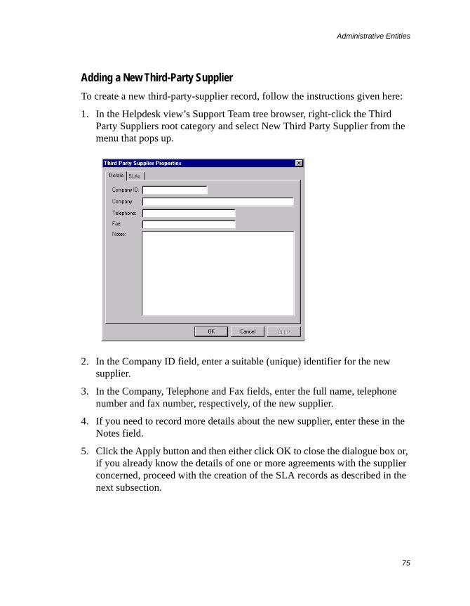
Administrative Entities
75
Adding a New Third-Party Supplier
To create a new third-party-supplier record, follow the instructions given here:
1. In the Helpdesk view’s Support Team tree browser, right-click the Third Party Suppliers root category and select New Third Party Supplier from the menu that pops up.
2. In the Company ID field, enter a suitable (unique) identifier for the new supplier.
3. In the Company, Telephone and Fax fields, enter the full name, telephone number and fax number, respectively, of the new supplier.
4. If you need to record more details about the new supplier, enter these in the Notes field.
5. Click the Apply button and then either click OK to close the dialogue box or, if you already know the details of one or more agreements with the supplier concerned, proceed with the creation of the SLA records as described in the next subsection.
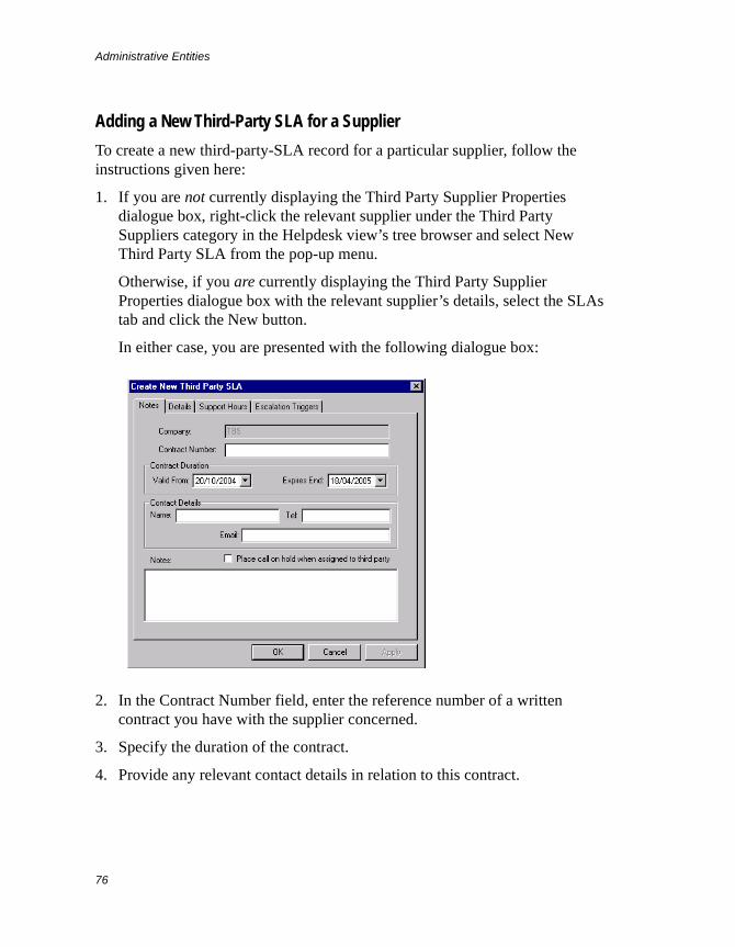
Administrative Entities
76
Adding a New Third-Party SLA for a Supplier
To create a new third-party-SLA record for a particular supplier, follow the instructions given here:
1. If you are not currently displaying the Third Party Supplier Properties dialogue box, right-click the relevant supplier under the Third Party Suppliers category in the Helpdesk view’s tree browser and select New Third Party SLA from the pop-up menu.
Otherwise, if you are currently displaying the Third Party Supplier Properties dialogue box with the relevant supplier’s details, select the SLAs tab and click the New button.
In either case, you are presented with the following dialogue box:
2. In the Contract Number field, enter the reference number of a written contract you have with the supplier concerned.
3. Specify the duration of the contract.
4. Provide any relevant contact details in relation to this contract.
Administrative Entities
77
5. If you want calls to go on hold automatically whenever they are assigned to this SLA, enable the checkbox option here. Note that on-hold placement can be automatic only where the Third Party SLAs option (in a given data dictionary’s Global Parameters) that forces the display of the Update Call dialogue whenever an analyst assigns a call to a third-party SLA is set to False (0).
6. If you wish to record more details about this contract, enter these in the Notes field.
7. Select the Details tab and follow the instructions to create a call-SLA record from step 4 of Adding a New SLA.
Modifying a Third-Party Supplier’s Details
To make changes to a third-party supplier’s record, first ensure that you are displaying the Helpdesk view’s Support Team tree browser. Then right-click the relevant supplier’s entry in the browser and select Properties from the menu that pops up. The same dialogue box as the one used for adding a supplier is displayed, and you can make the required changes there.
Removing a Third-Party Supplier
To delete a third-party supplier’s record, first ensure that you are displaying the Helpdesk view’s Support Team tree browser. Then right-click the relevant supplier’s entry in the browser and select Delete Third Party Supplier from the menu that pops up. The record is deleted immediately, without any confirmation being required. However, you will not be allowed to delete the record until you have first removed all SLAs associated with that third party.
Viewing a List of Third-Party SLAs
To display a list of third-party-SLA records associated with a given supplier, first ensure that you are displaying the Helpdesk view’s Support Team tree browser. Then right-click the relevant supplier’s entry in the browser and select Properties from the menu that pops up. Select the SLAs tab, which displays the required list as follows:
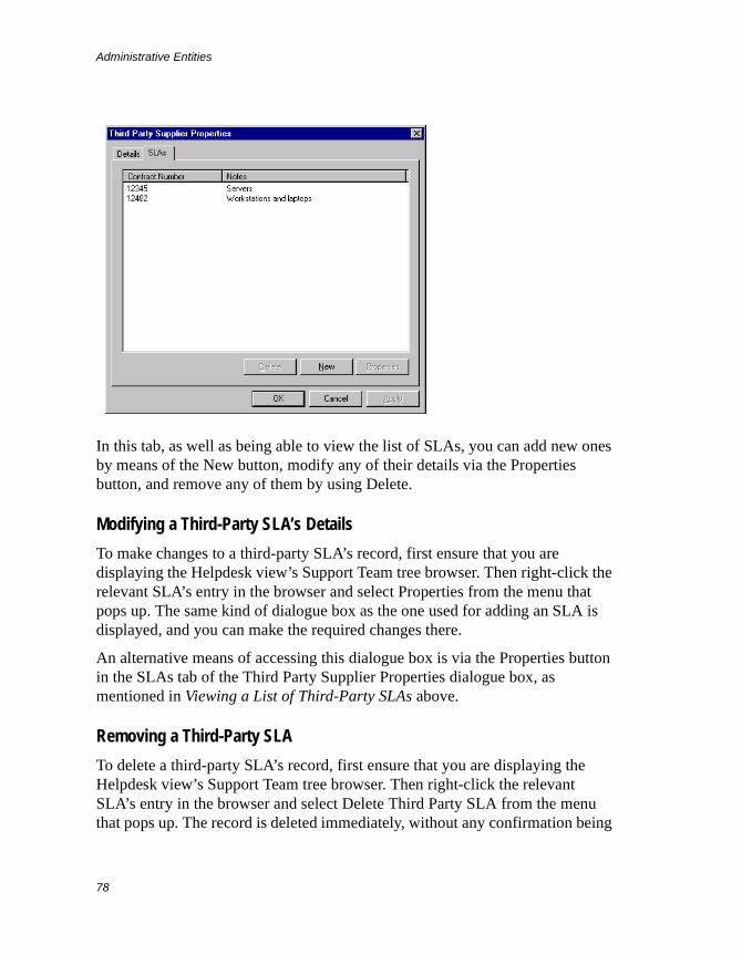
Administrative Entities
78
In this tab, as well as being able to view the list of SLAs, you can add new ones by means of the New button, modify any of their details via the Properties button, and remove any of them by using Delete.
Modifying a Third-Party SLA’s Details
To make changes to a third-party SLA’s record, first ensure that you are displaying the Helpdesk view’s Support Team tree browser. Then right-click the relevant SLA’s entry in the browser and select Properties from the menu that pops up. The same kind of dialogue box as the one used for adding an SLA is displayed, and you can make the required changes there.
An alternative means of accessing this dialogue box is via the Properties button in the SLAs tab of the Third Party Supplier Properties dialogue box, as mentioned in Viewing a List of Third-Party SLAs above.
Removing a Third-Party SLA
To delete a third-party SLA’s record, first ensure that you are displaying the Helpdesk view’s Support Team tree browser. Then right-click the relevant SLA’s entry in the browser and select Delete Third Party SLA from the menu that pops up. The record is deleted immediately, without any confirmation being
Administrative Entities
79
required. However, you will not be allowed to delete the record until all calls currently assigned to this SLA are re-assigned to analysts.
An alternative means of removing an SLA is via the Delete button in the SLAs tab of the Third Party Supplier Properties dialogue box, as mentioned in Viewing a List of Third-Party SLAs above.
Call ProfilesIn this section, you are first introduced to the idea of call profiles, and you are then shown how to perform each of the available call-profile management tasks in turn.
Introduction to Call Profiles
Supportworks has a facility for profiling support problems/requests and resolutions (fixes) by means of a hierarchical coding mechanism. A call profile is a multi-tiered thread of categories that describes a given type of problem/request or resolution. Such problems/requests and resolutions would be those that the support team has previously encountered, or is likely to encounter in the future. A profile describing a problem or request would be known as a problem/request profile, while one describing a resolution would be a resolution profile. A typical three-tier problem profile may, for example, be “Hardware > Printer > Poor Print Quality”.
You can create any number of call profiles, and these may be tiered down to any realistic level (although, for more than six tiers, you would have to increase the sizes of the relevant columns in the Open/Closed Call table and in the Call Profile tables). The profiles are held in a set of five closely-linked Call Profile tables. When you create a call profile, you construct it one tier at a time, starting at the most generic and working your way down to the most specific. You do this with the aid of a tree browser, which clearly shows the hierarchical structure of the profiles already created. You can extend an existing profile down to any permitted level. Against each tier of a profile, you can add a default text description of the problem/request or resolution, which would be more detailed than the brief text identifying each tier. You can also assign an SLA to a
Administrative Entities
80
(problem or request) profile, which would allow you to offer your customers different levels of support for different types of problem or request.
Once you have built up a set of call profiles, analysts will be able to select any of them, down to the desired level, when logging or closing/resolving a call. For call logging, it would be a problem/request profile that is allocated to the call, whereas for call closure/resolution, it would be a resolution profile. When encountering a new kind of problem/request (or registering a new kind of resolution) that is as yet unprofiled, the analyst may be able to select “Other” on any tier, or on all tiers, as a generic default. Such generic profiling is unhelpful as a future reference, and should be used only as a stopgap measure. At any time during the life of a call, it is possible for the analyst to change its profile to something more specific, provided that such a profile has been created in the meantime.
In any call-logging or call-closure/resolution situation, there is a facility available for making notes against the call. The analyst could either manually enter a suitable description of the problem/request or resolution, or could opt to instantly include the default text description associated with the selected profile, thus saving him or her the trouble of typing it out. The description could still be edited at that point, if necessary.
When you are in the process of constructing a call profile, a corresponding string of characters known as a call profile code is automatically built up at the same time. A call profile code is a shorthand representation of the associated call profile, and is used by the system internally to uniquely identify that profile (although the helpdesk administrator or group managers may need to be aware of it in some circumstances). Each tier of a call profile is represented by four characters of its profile code. Thus, a three-tier call profile would have a twelve-character call profile code. Although the profile codes are generated automatically by default, you have the option of entering them manually.
Profiling can prove invaluable for pinpointing problematic software or hardware, or areas of support weakness. Supportworks provides, for example, ready-to-run reports summarising open calls by problem type. You can also create your own reports to further extend the scope of problem analysis, and to implement any desired kind of resolution analysis. When examining or constructing reports based on problem or resolution types, you need to be aware of the meanings of all the stored profile codes.
Administrative Entities
81
Most helpdesk teams would be able to define most problems in three tiers. These, broadly, would be as follows:
(a) Hardware or software
(b) The application or machine that is malfunctioning
(c) The way in which it is malfunctioning
Similarly, fixes could typically be defined by the following three tiers:
(a) Hardware or software
(b) The application or machine that was malfunctioning
(c) The way in which the problem was resolved
It is not only problems and their fixes that need to be categorised. Customers may call to ask you questions or to ask you to do things for them. These calls and their resolutions will also require profiling. A different number of tiers may be appropriate for such profiles. For example, a resolution profile relating to the answer to a question is unlikely to be as deep as one relating to a problem fix.
For every helpdesk, there will be existing problem/request trends and corresponding resolutions that staff are already aware of, and it is these that your initially defined call profiles should reflect. Then, as the support team reports new kinds of problems/requests and resolutions, you can create call profiles for those, too, and therefore make them available for use on future calls.
Example
It has been decided that three tiers of problem profiles will be used. The first tier will indicate the two currently supported versions of FAST software, along with the two basic categories of supported in-house hardware (internal and mobile). For each version of FAST software, the second tier will indicate the main software modules: client, server and database. The third tier will indicate the actual nature of the problem, such as “incorrect result data” in relation to the database, for example. The hardware will be profiled in a similar way.
Detailed problem descriptions will be entered at the third tier for each problem profile, and auto-coding will be enabled to save time.
Administrative Entities
82
Call Profiles in Supportworks ITSM Applications
You can build call profiles for calls of all classes defined in an ITSM application. Thus, you would have Incident profiles, Problem/Known Error profiles and RFC profiles. With each of the call classes, you could typically interpret a problem/request profile as follows:
• For an Incident, it would categorise the problem as seen by the caller, or it would categorise their question or request.
• For a Problem, it would categorise the problem from an overall IT point of view. However, if you want automatic profile matching between Incidents and Problems to work, the set of Problem/Known Error profiles you make available to analysts must be the same as the set of Incident profiles.
• For an RFC, the problem profile would categorise the change that needs to be made.
A resolution profile might be interpreted as follows:
• For an Incident, it may categorise the fix, or the answer to the caller’s question. When there is an associated Problem or RFC, you would probably use the resolution profile of that.
• For a Known Error, it would categorise the fix or workaround.
• For an RFC, it would categorise the change made, in terms of whether the change was completed successfully or was failed, whether it was authorised or not, and so on.
Example
It has been decided that three tiers of call profiles will be enough. For problem/request profiles, the first tier will contain hardware, software and service exception (that is, problem) categories, along with a question category and a request category.
For each exception category, the second tier will contain various equipment, software and service types, with the relevant classes of call indicated. The question category will be subdivided into question types, and the request category will be split into hardware, software and service changes, and general actions. The change categories would be relevant to RFCs.
Administrative Entities
83
The third tier will contain the most specific subdivisions of the exception, question and request categories. For exceptions, detailed problem descriptions will be entered at the third tier of each problem/request profile. For questions and requests, the decriptions will not need to be so detailed.
Resolution profiles will broadly follow the hierarchical structure of the problem/request profiles.
Call Profiles in Supportworks CS Applications
You can build call profiles for calls of all classes defined in a Customer Support application. Thus, as well as problem profiles, you may also have analysis profiles and work profiles. With each of the call classes, you could typically interpret a problem/request profile as follows:
• For a Support Request, the problem/request profile would categorise the problem as seen by the caller, or it would categorise their question or request.
• For an Analysis Request, the analysis profile would categorise the investigation requirement.
• For a Work Request, the work profile would categorise the work that needs to be done.
A resolution profile might be interpreted as follows:
• For a Support Request, it may categorise the fix, or the answer to the caller’s question. When there is an associated Analysis or Work Request, you would probably use the resolution profile of that.
• For an Analysis Request, it would categorise the fix or workaround.
• For a Work Request, it would categorise the work done, in terms of whether the task was completed successfully or not, whether it was authorised or rejected, and so on.
Example
It has been decided that three tiers of call profiles will be enough. For problem/request profiles, the first tier will contain hardware and software exception (that is, problem) categories, along with a customer-question category and a customer-request category. These would be relevant to the Support Request call
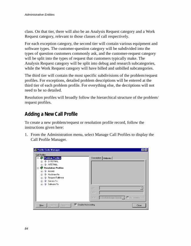
Administrative Entities
84
class. On that tier, there will also be an Analysis Request category and a Work Request category, relevant to those classes of call respectively.
For each exception category, the second tier will contain various equipment and software types. The customer-question category will be subdivided into the types of question customers commonly ask, and the customer-request category will be split into the types of request that customers typically make. The Analysis Request category will be split into debug and research subcategories, while the Work Request category will have billed and unbilled subcategories.
The third tier will contain the most specific subdivisions of the problem/request profiles. For exceptions, detailed problem descriptions will be entered at the third tier of each problem profile. For everything else, the decriptions will not need to be so detailed.
Resolution profiles will broadly follow the hierarchical structure of the problem/request profiles.
Adding a New Call Profile
To create a new problem/request or resolution profile record, follow the instructions given here:
1. From the Administration menu, select Manage Call Profiles to display the Call Profile Manager.
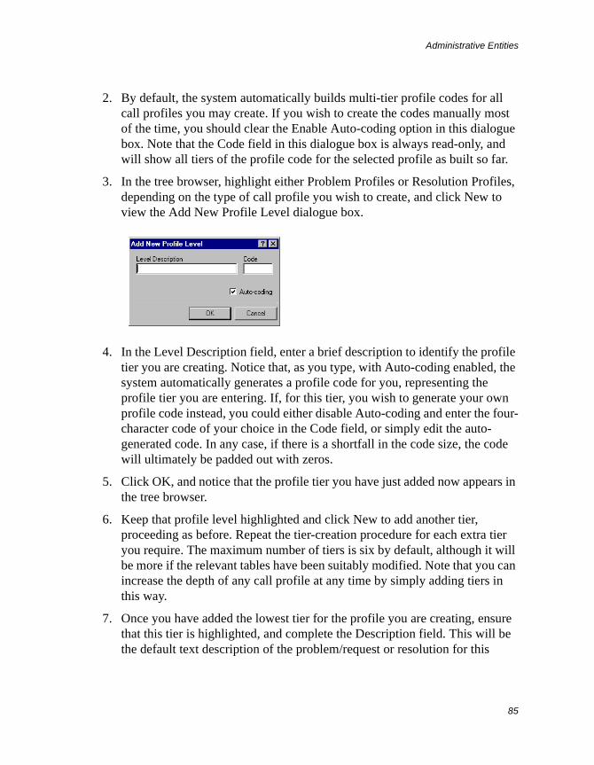
Administrative Entities
85
2. By default, the system automatically builds multi-tier profile codes for all call profiles you may create. If you wish to create the codes manually most of the time, you should clear the Enable Auto-coding option in this dialogue box. Note that the Code field in this dialogue box is always read-only, and will show all tiers of the profile code for the selected profile as built so far.
3. In the tree browser, highlight either Problem Profiles or Resolution Profiles, depending on the type of call profile you wish to create, and click New to view the Add New Profile Level dialogue box.
4. In the Level Description field, enter a brief description to identify the profile tier you are creating. Notice that, as you type, with Auto-coding enabled, the system automatically generates a profile code for you, representing the profile tier you are entering. If, for this tier, you wish to generate your own profile code instead, you could either disable Auto-coding and enter the four-character code of your choice in the Code field, or simply edit the auto-generated code. In any case, if there is a shortfall in the code size, the code will ultimately be padded out with zeros.
5. Click OK, and notice that the profile tier you have just added now appears in the tree browser.
6. Keep that profile level highlighted and click New to add another tier, proceeding as before. Repeat the tier-creation procedure for each extra tier you require. The maximum number of tiers is six by default, although it will be more if the relevant tables have been suitably modified. Note that you can increase the depth of any call profile at any time by simply adding tiers in this way.
7. Once you have added the lowest tier for the profile you are creating, ensure that this tier is highlighted, and complete the Description field. This will be the default text description of the problem/request or resolution for this
Administrative Entities
86
profile, and it can be made instantly available to any analyst logging or closing/resolving a call. Note that, although you could enter a text description at any tier (or at more than one tier) of a call profile, such text would tend to be most useful at the tier that will be used the most.
8. For a problem/request profile, assign an SLA, if required, by selection from the pick list in the SLA field. You could assign an SLA to any tier, or to more than one tier, of a call profile, depending on your specific requirements.
9. In the case of a problem/request profile, if your system is licensed to handle operator scripts, and you have created such a script, you can assign that script to the profile (at any tier, or tiers) by selecting it in the Script field. To make the script’s execution mandatory for analysts when they choose a problem/request profile to use in a call, enable the “Force execution” option.
10. If you are creating a problem/request profile and are required to specify attributes for a given tier, click the Attributes tab when highlighting the appropriate tier, and enter or select the necessary attributes. You can specify attributes at any tier, or tiers.
11. Click Close.
Viewing and Modifying an Existing Call Profile
To examine and edit a problem/request or resolution profile record, follow the instructions given here:
1. From the Administration menu, select Manage Call Profiles to view the Call Profile Manager.
2. In the tree browser, expand the relevant profile item down to the tier you want to view or modify, and ensure that this tier is highlighted.
3. If you wish, you may now edit the problem/request or resolution description.
4. If necessary, you may select another SLA or operator script, or you may want to enable or disable the “Force execution” option for the script.
5. If you wish to modify any attributes, you can do so with the Attributes tab displayed.
6. If you wish to change the brief description of the current tier, click Properties and carry out the required editing in the Level Description field of the
Administrative Entities
87
Modify Profile Description dialogue box. Note that you cannot edit the profile code displayed in the adjacent Code field. Click OK.
Deleting Existing Call Profile Tiers
To delete a previously created problem/request or resolution profile, or any lower portion of it, follow the instructions given here:
1. From the Administration menu, select Manage Call Profile Codes to view the Call Profile Manager.
2. In the tree browser, expand the relevant profile item down to the tier at which you want to delete it (including any “children” below it), and ensure that this tier is highlighted.
3. Click Delete. The selected profile tier and its children are deleted, as indicated by their disappearance from the tree.
4. Click Close.
Workflow TemplatesIn this section, you are first introduced to the idea of basic workflow in Supportworks, and to the use of workflow templates. You are then shown how to perform each of the available workflow-template management tasks in turn.
To find out about more advanced business-process management (if applicable to the particular Supportworks application you have purchased), please see the relevant template-specific Administrator Guide.
Introduction to Workflow
The organisation of any part of a business process that involves task management within a team can be represented as a workflow. In the context of actioning a helpdesk call, the workflow would procedurally specify the work that has to be carried out in order to resolve that call, and would also indicate which analyst or group is to be assigned to each individual work item. Work items would be grouped together within named worklists. A worklist can be
Administrative Entities
88
regarded as a distinct stage in the process of resolving a call. It is possible to apply one or more worklists to any given call.
A work item within a worklist applied to a call would be a specific helpdesk task that has to be performed, either by the call owner or by a team member who may not be responsible for the call as a whole. Any number of worklists, and any number of work items within them, can be included in a call. If, for example, an internal customer’s workstation has sustained widespread hardware and software damage, it may be necessary to create a “hardware” worklist and a “software” worklist against the call logged. In each worklist, several work items would be specified, each to be dealt with by perhaps a different specialist. Each specialist would be assigned responsibility for the work item(s) in their field of expertise.
Work-item assignees do not always need to be specialists, however, as work items can be defined purely for the purpose of sharing the workload necessary to resolve a call. In such a case, it would not matter very much who was assigned which work item, although it may still be useful to exercise some kind of preference. Note that support groups can be assignees as well.
You can specify a list of work items as being open or sequential. The items in an open worklist can be completed in any order, while those in a sequential worklist have to follow the stated order. The worklists themselves, on the other hand, as they represent stages in the workflow, always follow each other in sequence. Thus, in the example above, the workflow would most likely be organised such that the hardware worklist precedes the software worklist.
All worklists logged against a call must be completed before you can close or resolve the call, and a worklist will not be marked as completed until all of its constituent work items have, in their turn, been completed. When defining a work item, you can specify whether absolutely anyone in the support team will be allowed to register the task as complete, whether that action is to be restricted to members of the assignee’s group, or whether it is to be restricted to the individual assignee.
There are two possible ways in which you can create a workflow for a call:
• You can create it individually at the time of the call. This method would be appropriate for calls that are non-routine and are handled on an ad hoc basis.
Administrative Entities
89
• You can create sets of workflows in advance and save them as templates, any of which you or a member of the team can subsequently select when logging a call. This would be appropriate for routine and standardised calls.
The templates employed in the second method are in fact records held in the Workflow Template table. There is no need to populate this table when first setting the system up unless perhaps you already have some standard assignable tasks in mind.
Example
When a new employee joins DO IT, the manager of that individual’s department would normally contact the support team to arrange for the usual workstation-related new-starter procedures to be carried out. These procedures might include the connecting up of a new desktop PC, the creation of a new Windows NT Domain account, the installation of Windows NT, the installation of other applications, and so on.
As each of these work items involves a different specialist in the support team, it would make sense to include appropriate workflow elements in all such support calls. Furthermore, since the required set of work items would be the same every time, creating the workflow as a template would be the preferred way of specifying them.
A brief analysis of the work items involved in the new-starter process indicates that they are not complex enough to warrant the introduction of more than one major workflow stage. Thus, a single worklist containing all the required work items would suffice. Because the starting of each task is dependent on the previous task being completed, the work items would need to be specified as sequential.
In accordance with the DO IT support team’s usual practices, the responsibility for completing all routine work items other than the installation of standard office applications rests with the individual assigned to the job. However, for applications, the responsibility is widened to the assignee’s entire group. These responsibilities will be reflected in the workflow template.
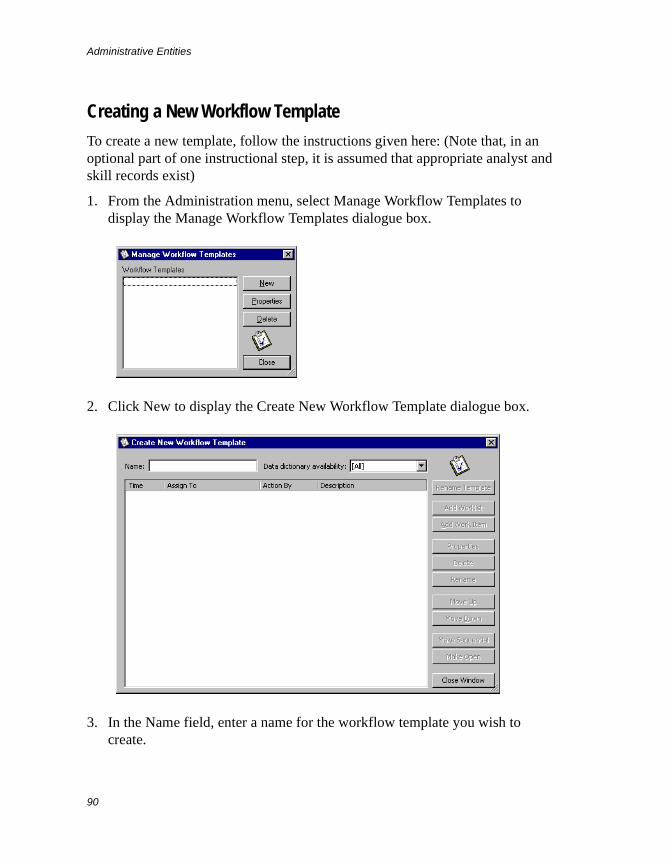
Administrative Entities
90
Creating a New Workflow Template
To create a new template, follow the instructions given here: (Note that, in an optional part of one instructional step, it is assumed that appropriate analyst and skill records exist)
1. From the Administration menu, select Manage Workflow Templates to display the Manage Workflow Templates dialogue box.
2. Click New to display the Create New Workflow Template dialogue box.
3. In the Name field, enter a name for the workflow template you wish to create.
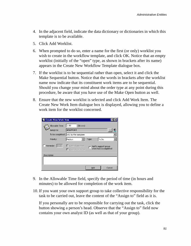
Administrative Entities
91
4. In the adjacent field, indicate the data dictionary or dictionaries in which this template is to be available.
5. Click Add Worklist.
6. When prompted to do so, enter a name for the first (or only) worklist you wish to create in the workflow template, and click OK. Notice that an empty worklist (initially of the “open” type, as shown in brackets after its name) appears in the Create New Workflow Template dialogue box.
7. If the worklist is to be sequential rather than open, select it and click the Make Sequential button. Notice that the words in brackets after the worklist name now indicate that its constituent work items are to be sequential. Should you change your mind about the order type at any point during this procedure, be aware that you have use of the Make Open button as well.
8. Ensure that the new worklist is selected and click Add Work Item. The Create New Work Item dialogue box is displayed, allowing you to define a work item for the worklist concerned.
9. In the Allowable Time field, specify the period of time (in hours and minutes) to be allowed for completion of the work item.
10. If you want your own support group to take collective responsibility for the task to be carried out, leave the content of the “Assign to” field as it is.
If you personally are to be responsible for carrying out the task, click the button showing a person’s head. Observe that the “Assign to” field now contains your own analyst ID (as well as that of your group).
Administrative Entities
92
Otherwise, click the button with three dots to display the Choose Assignee dialogue box. From the tree browser, you can select the support group or analyst to which you wish to assign the work item. If you need to base your choice on respective skills, click the Skills tab, select a group and skill as necessary, and select the required analyst. In either case, click OK, and observe that the “Assign to” field in the Create New Work Item dialogue box now contains the selected analyst or group. (Alternatively, you could have simply double-clicked the item in either the browser or the Skills list.)
11. In the next field, use the drop-down list to specify whether the work item can be completed only by the assignee, by any member of the assignee’s group, or by anyone in the support team.
12. In the Priority field, select an appropriate level of priority for the work item, indicating how important you think it is.
13. In the Type field, select the category under which the work item should fall.
14. If you want the system to send the assignee and/or the call owner an automatic reminder of the work-item deadline shortly before expiry of the allowed time, enable the relevant options and specify how long (in hours and minutes) before expiry the reminder should be sent.
15. If you want the system to notify all members of the assigned group of the completion of the work item, enable the relevant option.
16. In the Description field, type a suitable description of the work item.
17. Click Add, and notice that the work item you have just defined has been added to the selected worklist in the Create New Workflow Template dialogue box.
18. Repeat step 8 to step 17 for each additional work item you want to define.
19. If you wish to delete a work item, select it and click the Delete button.
20. If you wish to rearrange the work items in the list, you can do that by selecting individual items and clicking the Move Up or Move Down button.
21. Repeat step 5 to step 20 for each additional worklist you want to create.
22. If you wish to delete a worklist, select it and click the Delete button.
Administrative Entities
93
23. If you wish to rename a worklist, select it, click the Rename button, enter its new name at the prompt, and click OK.
24. If you have created more than one worklist in this template, and you wish to rearrange these on the list, you can do that by selecting them individually and clicking the Move Up or Move Down button.
25. If you wish to rename the template, click the Rename Template button, enter its new name at the prompt, and click OK.
26. Click Close Window, and notice the addition of the new template to the list in the Manage Workflow Templates dialogue box.
27. Click Close.
Viewing and Modifying an Existing Workflow Template
To examine and edit a template, follow the instructions given here:
1. From the Administration menu, select Manage Workflow Templates to display the Manage Workflow Templates dialogue box.
2. Select a template from the list and click Properties to display the Edit Workflow Template dialogue box. This is similar to the Create New Workflow Template dialogue box.
3. To create a new worklist for the template, click Add Worklist and proceed as before.
4. To define a new work item within a worklist, select the worklist concerned, click Add Work Item, and proceed as before.
5. To modify an existing work item, select it from the relevant worklist and click Properties. The Work Item Properties dialogue box is displayed, which is similar to the Create New Work Item dialogue box. You can change the contents of any of the fields as before. Click Update when you are done.
6. To delete a work item or worklist, use the Delete button as before.
7. To rename a worklist, use the Delete button as before.
8. To rearrange the work items or worklists, use the Move Up and Move Down buttons as before.
Administrative Entities
94
9. To rename the template, use the Rename Template button as before.
10. Click Close Window and then Close.
Note A workflow template that is empty cannot exist as a named entity. Therefore, if you have deleted all the contents of a template, the template itself will also be deleted when you close the Edit Workflow Template (or Create New Workflow Template) dialogue box.
Deleting an Existing Workflow Template
To delete a template, follow the instructions given here:
1. From the Administration menu, select Manage Workflow Templates to display the Manage Workflow Templates dialogue box.
2. To delete a template, select it from the list and click Delete.
3. Click Close.
You can also delete a template by simply deleting all of its contents, as mentioned in the note at the end of Viewing and Modifying an Existing Workflow Template.
User-Related Data and Settings
95
User-Related Data and Settings
User-related details consist of the following:
• The skills of analysts
• Support groups and their characteristics
• Support analysts and their characteristics
The details of each skill and the characteristics of each group or analyst are stored in a record in the appropriate table.
Before your Supportworks system goes live, you will have to ensure that at least all the required group and analyst records exist and contain the correct data. Equally, if your system has been live for a while, you may wish to make changes to some of these records. In either case, you will be using a relevant management facility to achieve your goal.
This chapter describes each of the user-related entities and the facilities available for managing them.
SkillsSkill records are designed to hold sets of suitably categorised skills information. The skills defined in these records would be all of those possessed by the individuals in the entire support team. Once defined, a skill can be associated with one or more analysts. Also, multiple skills can be associated with any given analyst. (Note that such associations are performed within the relevant analyst record.)
Furthermore, the administrator can give analysts a performance and experience rating with respect to each of their associated skills. The administrator or suitably authorised analysts would then be able to assign calls to individuals based on their specialist skill sets and/or their levels of competence in those areas.
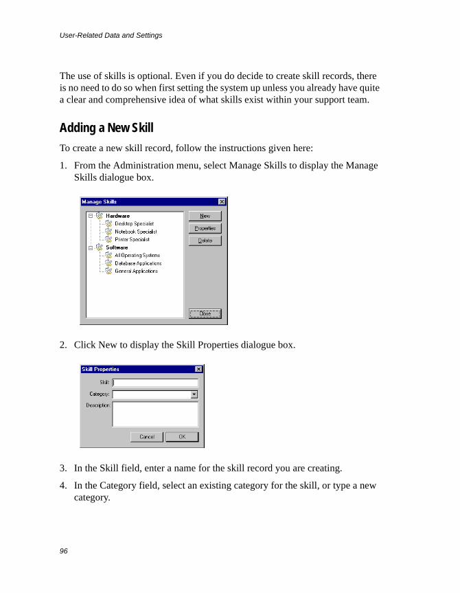
User-Related Data and Settings
96
The use of skills is optional. Even if you do decide to create skill records, there is no need to do so when first setting the system up unless you already have quite a clear and comprehensive idea of what skills exist within your support team.
Adding a New Skill
To create a new skill record, follow the instructions given here:
1. From the Administration menu, select Manage Skills to display the Manage Skills dialogue box.
2. Click New to display the Skill Properties dialogue box.
3. In the Skill field, enter a name for the skill record you are creating.
4. In the Category field, select an existing category for the skill, or type a new category.
User-Related Data and Settings
97
5. In the Description field, type some text describing the skill.
6. Click OK. The new record is created.
7. Click Close.
Viewing and Modifying the Details of an Existing Skill
To examine and edit a skill record, follow the instructions given here:
1. From the Administration menu, select Manage Skills to view the Manage Skills dialogue box.
2. In the tree browser, highlight the required skill and click Properties to display the Skill Properties dialogue box.
3. You can now edit any of the fields in the record.
4. Click OK to save your changes.
5. Click Close.
Deleting an Existing Skill
To delete a skill record, follow the instructions given here:
1. From the Administration menu, select Manage Skills to view the Manage Skills dialogue box.
2. In the tree browser, highlight the relevant skill and click Delete. The record is deleted.
3. Click Close.
Support GroupsSupportworks allows you to divide up your support organisation into groups, each having one or more support analysts and possibly further groups as members. The records in which the groups are defined are referenced by the support-analyst records.
User-Related Data and Settings
98
In a support-group record, not only can you specify a number of appropriate attributes, but you can also reserve user licences for that group.
The support groups can be differentiated from each other in any way that may be appropriate to your support operation: for example, by internal and external support responsibilities, or by skill sets. Any such classification scheme should allow easy and logical access, via the analyst-selection tree browser, to specific analysts for assigning and tracking calls.
Each Supportworks installation is provided with a default group to begin with whose ID is SUPPORT, and whose sole member is the Administrator. You can easily expand from this to build a grouping structure that is suitable for your support team.
Adding a New Support Group
To create a new support-group record, follow the instructions given here:
1. In the Support Team tree browser, select Supportworks Helpdesk or whichever group you want the new group to belong to. This selection may be a left click or a right click. (Note that if you are not in a Helpdesk view, the selection will default to Supportworks Helpdesk.)
2. From the File menu, or from the menu that pops up on a right click, select New > Support Group to display the Add New Support Group dialogue box.
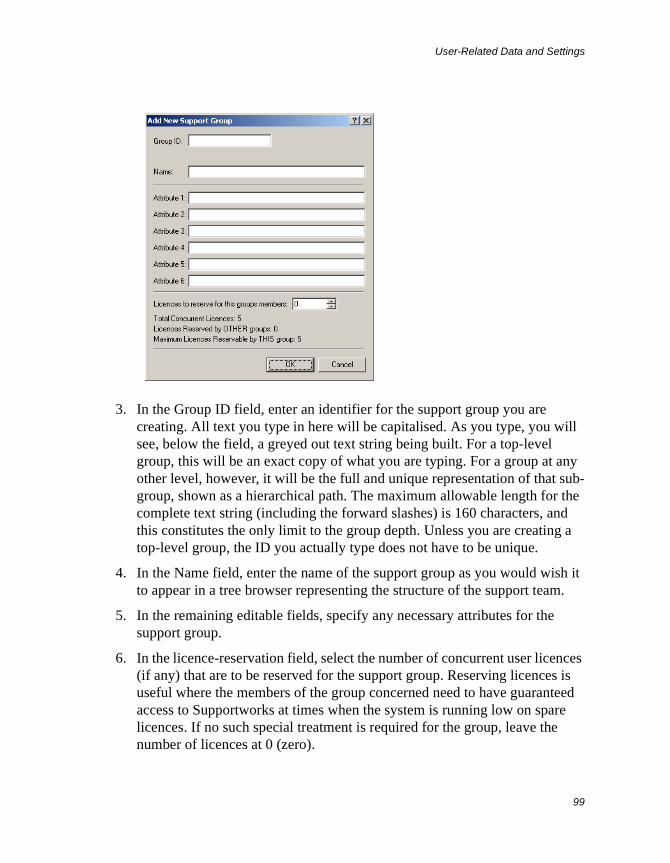
User-Related Data and Settings
99
3. In the Group ID field, enter an identifier for the support group you are creating. All text you type in here will be capitalised. As you type, you will see, below the field, a greyed out text string being built. For a top-level group, this will be an exact copy of what you are typing. For a group at any other level, however, it will be the full and unique representation of that sub-group, shown as a hierarchical path. The maximum allowable length for the complete text string (including the forward slashes) is 160 characters, and this constitutes the only limit to the group depth. Unless you are creating a top-level group, the ID you actually type does not have to be unique.
4. In the Name field, enter the name of the support group as you would wish it to appear in a tree browser representing the structure of the support team.
5. In the remaining editable fields, specify any necessary attributes for the support group.
6. In the licence-reservation field, select the number of concurrent user licences (if any) that are to be reserved for the support group. Reserving licences is useful where the members of the group concerned need to have guaranteed access to Supportworks at times when the system is running low on spare licences. If no such special treatment is required for the group, leave the number of licences at 0 (zero).
User-Related Data and Settings
100
7. Click OK. You now have a new support-group record.
Viewing and Modifying the Details of an Existing Support Group
To examine and edit a support-group record, follow the instructions given here:
1. On the Supportworks shortcut bar, select a Helpdesk view.
2. In the tree browser, right-click the support group whose details you wish to view or edit, and select Properties from the pop-up menu. The Edit Support Group dialogue box is displayed, showing the same fields as the Add New Support Group dialogue box.
3. You can now edit the contents of the Group Display Name field if you wish, or modify any of the attributes.
4. Click OK. Your changes are saved.
Deleting an Existing Support Group
To delete a support-group record, follow the instructions given here:
1. On the Supportworks shortcut bar, select a Helpdesk view.
2. In the tree browser, right-click the support group you wish to delete, and select Delete from the pop-up menu. Once you have confirmed the proposed action, the record is deleted.
Support AnalystsSupport-analyst records hold information and settings relating to every member of the support team. The information consists mainly of contact and authentication details, and indications of group membership and locale. In addition, there are settings that define the rights the individual has been given to carry out specific actions in Supportworks, and those that define the default operational options that are associated with the individual. It is also possible to set an availability status, select the individual’s skills from the skills record, and manage their library resources.
User-Related Data and Settings
101
The analyst records are actually user accounts. They govern the ability of Supportworks users to log into the system as analysts, managers or administrators, and to use the system in a manner consistent with their respective rights.
On initial system installation, you will find that one analyst record already exists: an account for the user named Administrator. You are warned not to delete the Administrator account unless you are prepared to permanently do without the rights associated with the helpdesk administrator’s role, as this account is initially the only one that possesses such rights.
Before you start creating your own analyst records, you would probably want to ensure that you have created all the required group records, and possibly all the skill records.
If third-party SLAs are enabled, the information on third-party service suppliers would be stored as analyst records.
Adding a New Support Analyst
To create a new support-analyst record, follow the instructions given here:
1. From the File menu, select New > Support Analyst to display the Add New Support Analyst dialogue box.
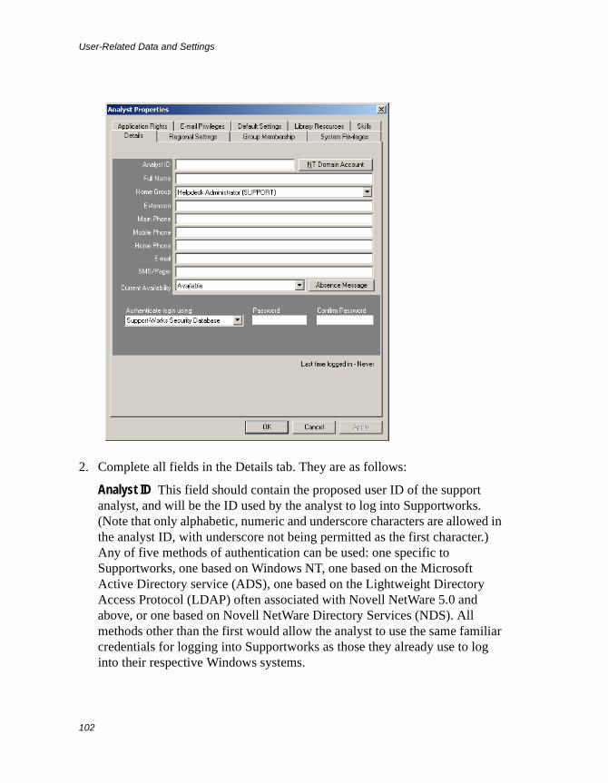
User-Related Data and Settings
102
2. Complete all fields in the Details tab. They are as follows:
Analyst ID This field should contain the proposed user ID of the support analyst, and will be the ID used by the analyst to log into Supportworks. (Note that only alphabetic, numeric and underscore characters are allowed in the analyst ID, with underscore not being permitted as the first character.) Any of five methods of authentication can be used: one specific to Supportworks, one based on Windows NT, one based on the Microsoft Active Directory service (ADS), one based on the Lightweight Directory Access Protocol (LDAP) often associated with Novell NetWare 5.0 and above, or one based on Novell NetWare Directory Services (NDS). All methods other than the first would allow the analyst to use the same familiar credentials for logging into Supportworks as those they already use to log into their respective Windows systems.
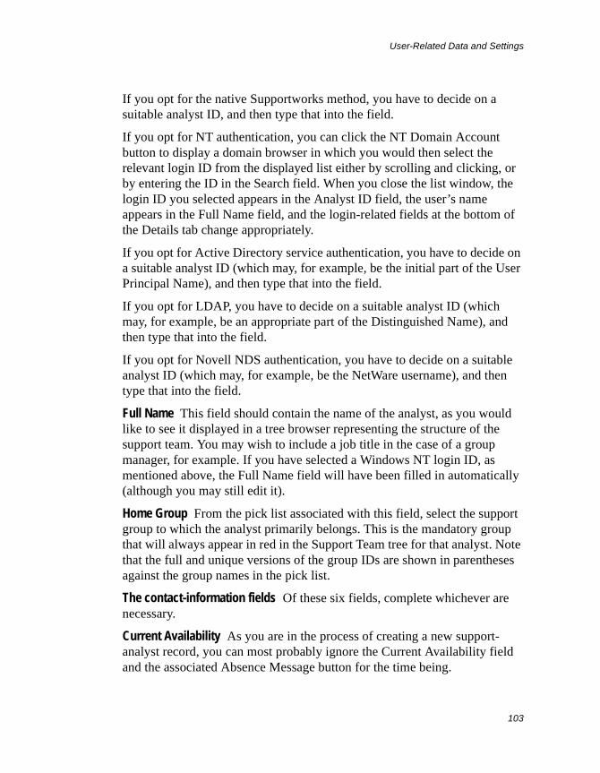
User-Related Data and Settings
103
If you opt for the native Supportworks method, you have to decide on a suitable analyst ID, and then type that into the field.
If you opt for NT authentication, you can click the NT Domain Account button to display a domain browser in which you would then select the relevant login ID from the displayed list either by scrolling and clicking, or by entering the ID in the Search field. When you close the list window, the login ID you selected appears in the Analyst ID field, the user’s name appears in the Full Name field, and the login-related fields at the bottom of the Details tab change appropriately.
If you opt for Active Directory service authentication, you have to decide on a suitable analyst ID (which may, for example, be the initial part of the User Principal Name), and then type that into the field.
If you opt for LDAP, you have to decide on a suitable analyst ID (which may, for example, be an appropriate part of the Distinguished Name), and then type that into the field.
If you opt for Novell NDS authentication, you have to decide on a suitable analyst ID (which may, for example, be the NetWare username), and then type that into the field.
Full Name This field should contain the name of the analyst, as you would like to see it displayed in a tree browser representing the structure of the support team. You may wish to include a job title in the case of a group manager, for example. If you have selected a Windows NT login ID, as mentioned above, the Full Name field will have been filled in automatically (although you may still edit it).
Home Group From the pick list associated with this field, select the support group to which the analyst primarily belongs. This is the mandatory group that will always appear in red in the Support Team tree for that analyst. Note that the full and unique versions of the group IDs are shown in parentheses against the group names in the pick list.
The contact-information fields Of these six fields, complete whichever are necessary.
Current Availability As you are in the process of creating a new support-analyst record, you can most probably ignore the Current Availability field and the associated Absence Message button for the time being.
User-Related Data and Settings
104
Authenticate login using The item in this field indicates the method of authentication that Supportworks must use when the analyst logs into the system. By default, the setting is Supportworks Security Database, which is the method specific to Supportworks. With this setting, you will have to decide on an initial password for the analyst and then enter it in both of the password fields provided.
If you have selected a Windows NT account as the analyst ID (as mentioned above), the setting will have automatically changed to NT Domain Authentication, and the password fields will have changed to a Domain field. You should check that the domain indicated is correct.
If you want the analyst to use the Microsoft Active Directory service (ADS) as the means of authentication, you should select Windows 2000 Active Directory via the drop-down list, whereupon the password fields change to one in which you must enter a valid User Principal Name (UPN). A UPN is similar in format to an Internet e-mail address.
If you want the analyst to use LDAP as the means of authentication, you should select Lightweight Directory Access Protocol via the drop-down list, whereupon the password fields change to one in which you must specify an LDAP server and a valid Distinguished Name. Enter the name or IP address of a suitable computer running LDAP (perhaps a Novell NetWare server), then type a forward slash (/), and finally enter the analyst’s Distinguished Name as recognised by the LDAP server. An example might be as follows: SERVER01/o=hornbill,cn=steve.
If you want the analyst to use Novell NDS as the means of authentication, you should select Novell NDS Authentication via the drop-down list, whereupon the password fields change to one in which you must enter a valid NDS username or, if this is not unique within your organisation, a fully qualified NDS user ID. The latter option would be in the following format:<username>.<context>.<tree>
where <username> is the lowest-level unit of the ID, <context> is any number of levels of organisational unit (separated from each other by single dots, with the lowest level first), and <tree> is the highest-level organisational unit. A typical example (with two context levels) might be: jsmith.development.acmeUK.acmecorp.
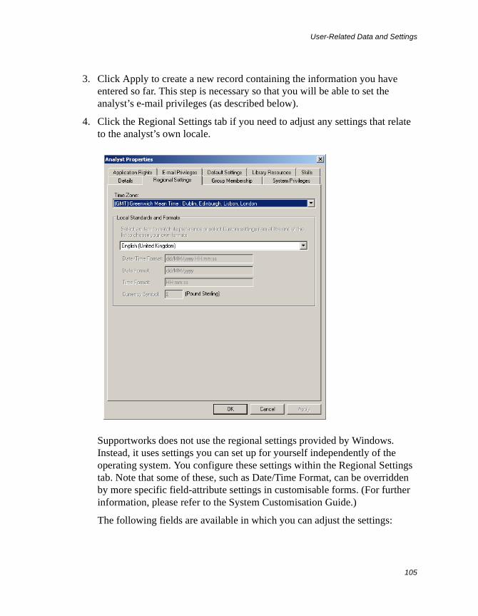
User-Related Data and Settings
105
3. Click Apply to create a new record containing the information you have entered so far. This step is necessary so that you will be able to set the analyst’s e-mail privileges (as described below).
4. Click the Regional Settings tab if you need to adjust any settings that relate to the analyst’s own locale.
Supportworks does not use the regional settings provided by Windows. Instead, it uses settings you can set up for yourself independently of the operating system. You configure these settings within the Regional Settings tab. Note that some of these, such as Date/Time Format, can be overridden by more specific field-attribute settings in customisable forms. (For further information, please refer to the System Customisation Guide.)
The following fields are available in which you can adjust the settings:
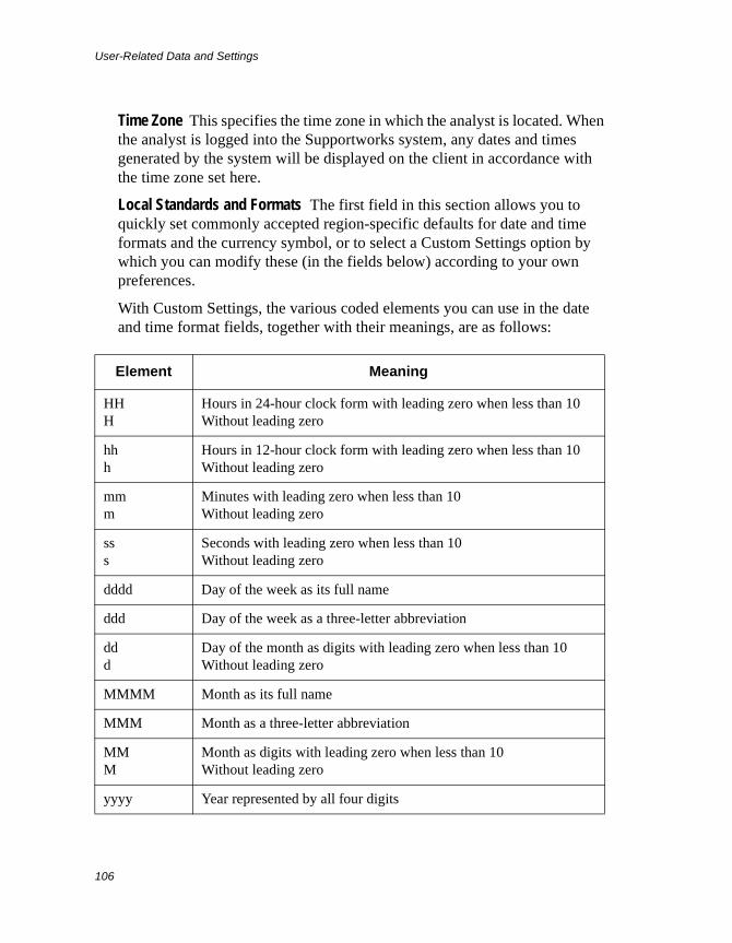
User-Related Data and Settings
106
Time Zone This specifies the time zone in which the analyst is located. When the analyst is logged into the Supportworks system, any dates and times generated by the system will be displayed on the client in accordance with the time zone set here.
Local Standards and Formats The first field in this section allows you to quickly set commonly accepted region-specific defaults for date and time formats and the currency symbol, or to select a Custom Settings option by which you can modify these (in the fields below) according to your own preferences.
With Custom Settings, the various coded elements you can use in the date and time format fields, together with their meanings, are as follows:
Element Meaning
HHH
Hours in 24-hour clock form with leading zero when less than 10Without leading zero
hhh
Hours in 12-hour clock form with leading zero when less than 10Without leading zero
mmm
Minutes with leading zero when less than 10Without leading zero
sss
Seconds with leading zero when less than 10Without leading zero
dddd Day of the week as its full name
ddd Day of the week as a three-letter abbreviation
ddd
Day of the month as digits with leading zero when less than 10Without leading zero
MMMM Month as its full name
MMM Month as a three-letter abbreviation
MMM
Month as digits with leading zero when less than 10Without leading zero
yyyy Year represented by all four digits
User-Related Data and Settings
107
Along with the elements above, you can enter any other displayable characters, which the system will interpret literally. Thus, the following time and date formats might produce respective times and dates as shown:
HH:mm:ss = 12:30:59hh:mm:ss tt = 05:25:41 PMdd-MM-yyyy = 03-09-2007dddd, dd of MMMM, yyyy = Tuesday, 03 of September, 2007
5. If the analyst is also a member of other support groups, click the Group Membership tab to define these additional memberships.
yy Year as last two digits (with leading zero when less than 10)
tt AM or PM for 12-hour clock
Element Meaning
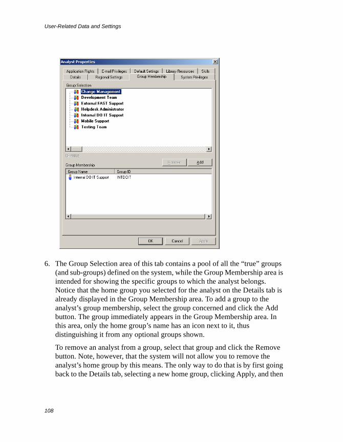
User-Related Data and Settings
108
6. The Group Selection area of this tab contains a pool of all the “true” groups (and sub-groups) defined on the system, while the Group Membership area is intended for showing the specific groups to which the analyst belongs. Notice that the home group you selected for the analyst on the Details tab is already displayed in the Group Membership area. To add a group to the analyst’s group membership, select the group concerned and click the Add button. The group immediately appears in the Group Membership area. In this area, only the home group’s name has an icon next to it, thus distinguishing it from any optional groups shown.
To remove an analyst from a group, select that group and click the Remove button. Note, however, that the system will not allow you to remove the analyst’s home group by this means. The only way to do that is by first going back to the Details tab, selecting a new home group, clicking Apply, and then
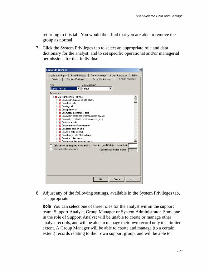
User-Related Data and Settings
109
returning to this tab. You would then find that you are able to remove the group as normal.
7. Click the System Privileges tab to select an appropriate role and data dictionary for the analyst, and to set specific operational and/or managerial permissions for that individual.
8. Adjust any of the following settings, available in the System Privileges tab, as appropriate:
Role You can select one of three roles for the analyst within the support team: Support Analyst, Group Manager or System Administrator. Someone in the role of Support Analyst will be unable to create or manage other analyst records, and will be able to manage their own record only to a limited extent. A Group Manager will be able to create and manage (to a certain extent) records relating to their own support group, and will be able to
User-Related Data and Settings
110
manage their own record to the same extent. A System Administrator will be able to create and fully manage records relating to the entire support team. See Analyst Management Capabilities Relating to Each Role on page 122 for more precise details.
Data Dictionary A data dictionary is a system look-up table that defines major elements of the Supportworks client’s appearance and operation. One or more data dictionaries (based on the Default or other templates) will have been created for you to produce customised versions of the client, suitable for your particular support operation or the different offerings available from it. Any such customised version is known as an application. If multiple applications (data dictionaries) are available, each may perhaps be intended for analysts in a different support group. It is also possible that analysts having multiple responsibilities may need to use more than one application.
For the analyst whose record you are creating, you should select here the data dictionary that is relevant to them, or (in a multi-role case) the one that is relevant most of the time. Whichever data dictionary you select will be the one that is going to be loaded by default whenever the analyst logs into their Supportworks client account.
Permissions In Supportworks, there are a large number of rights, regarding very specific client operations, that analysts can be given on an individual basis. They fall into the following categories: Call Management Rights (A and B), System Management Rights, Desktop Workspace Rights, Data Dictionary Rights, Global SQL Database Rights and Database Management Rights. By default, every new support-analyst record is initially set with most rights disabled, as depicted by the red crosses against the items in the scrollable list.
You have to examine carefully the list of permissions and decide which of these to enable for the analyst whose record you are creating. To give the right to perform a particular operation, click the item concerned. The red cross changes to a green check-mark. To subsequently revoke a right, click the item again. If you click a category, all permissions within it are enabled or disabled.
Calls cannot be assigned to this analyst If, as helpdesk administrator or group manager, you wish to prevent calls from being assigned to the analyst (for example, to reduce their workload), you should enable this option.
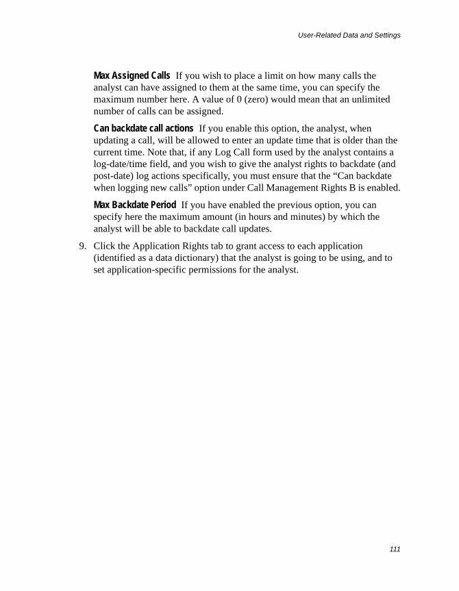
User-Related Data and Settings
111
Max Assigned Calls If you wish to place a limit on how many calls the analyst can have assigned to them at the same time, you can specify the maximum number here. A value of 0 (zero) would mean that an unlimited number of calls can be assigned.
Can backdate call actions If you enable this option, the analyst, when updating a call, will be allowed to enter an update time that is older than the current time. Note that, if any Log Call form used by the analyst contains a log-date/time field, and you wish to give the analyst rights to backdate (and post-date) log actions specifically, you must ensure that the “Can backdate when logging new calls” option under Call Management Rights B is enabled.
Max Backdate Period If you have enabled the previous option, you can specify here the maximum amount (in hours and minutes) by which the analyst will be able to backdate call updates.
9. Click the Application Rights tab to grant access to each application (identified as a data dictionary) that the analyst is going to be using, and to set application-specific permissions for the analyst.
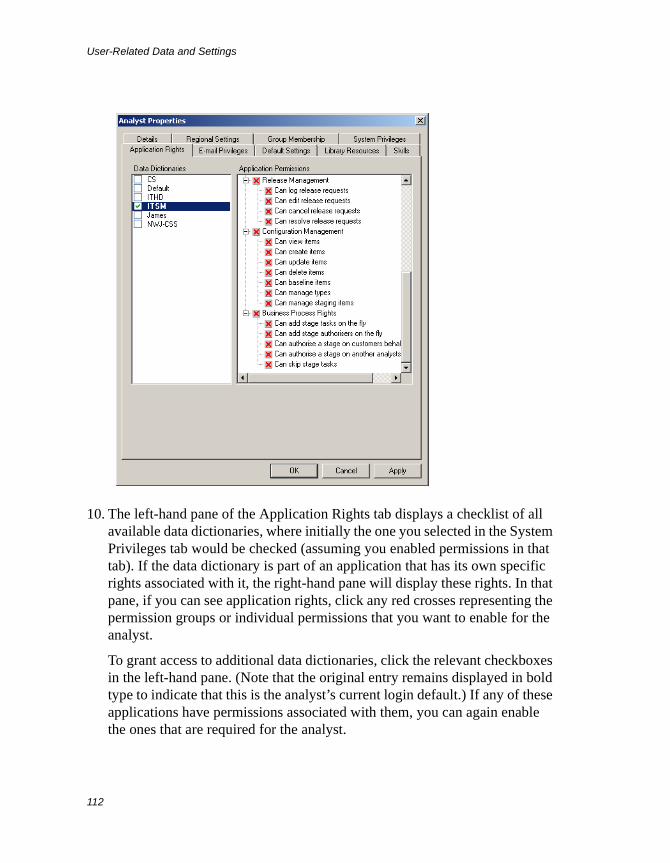
User-Related Data and Settings
112
10. The left-hand pane of the Application Rights tab displays a checklist of all available data dictionaries, where initially the one you selected in the System Privileges tab would be checked (assuming you enabled permissions in that tab). If the data dictionary is part of an application that has its own specific rights associated with it, the right-hand pane will display these rights. In that pane, if you can see application rights, click any red crosses representing the permission groups or individual permissions that you want to enable for the analyst.
To grant access to additional data dictionaries, click the relevant checkboxes in the left-hand pane. (Note that the original entry remains displayed in bold type to indicate that this is the analyst’s current login default.) If any of these applications have permissions associated with them, you can again enable the ones that are required for the analyst.
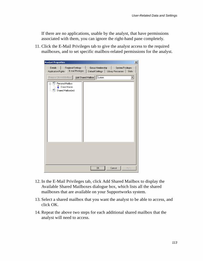
User-Related Data and Settings
113
If there are no applications, usable by the analyst, that have permissions associated with them, you can ignore the right-hand pane completely.
11. Click the E-Mail Privileges tab to give the analyst access to the required mailboxes, and to set specific mailbox-related permissions for the analyst.
12. In the E-Mail Privileges tab, click Add Shared Mailbox to display the Available Shared Mailboxes dialogue box, which lists all the shared mailboxes that are available on your Supportworks system.
13. Select a shared mailbox that you want the analyst to be able to access, and click OK.
14. Repeat the above two steps for each additional shared mailbox that the analyst will need to access.
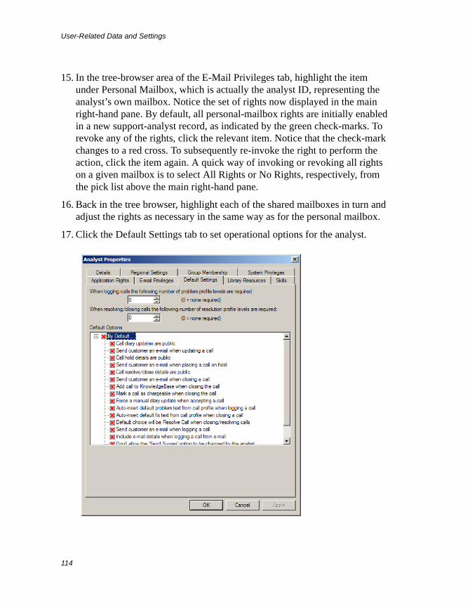
User-Related Data and Settings
114
15. In the tree-browser area of the E-Mail Privileges tab, highlight the item under Personal Mailbox, which is actually the analyst ID, representing the analyst’s own mailbox. Notice the set of rights now displayed in the main right-hand pane. By default, all personal-mailbox rights are initially enabled in a new support-analyst record, as indicated by the green check-marks. To revoke any of the rights, click the relevant item. Notice that the check-mark changes to a red cross. To subsequently re-invoke the right to perform the action, click the item again. A quick way of invoking or revoking all rights on a given mailbox is to select All Rights or No Rights, respectively, from the pick list above the main right-hand pane.
16. Back in the tree browser, highlight each of the shared mailboxes in turn and adjust the rights as necessary in the same way as for the personal mailbox.
17. Click the Default Settings tab to set operational options for the analyst.
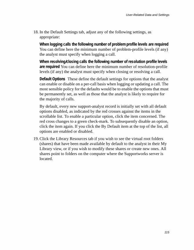
User-Related Data and Settings
115
18. In the Default Settings tab, adjust any of the following settings, as appropriate:
When logging calls the following number of problem profile levels are required You can define here the minimum number of problem-profile levels (if any) the analyst must specify when logging a call.
When resolving/closing calls the following number of resolution profile levels are required You can define here the minimum number of resolution-profile levels (if any) the analyst must specify when closing or resolving a call.
Default Options These define the default settings for options that the analyst can enable or disable on a per-call basis when logging or updating a call. The most sensible policy for the defaults would be to enable the options that must be permanently set, as well as those that the analyst is likely to require for the majority of calls.
By default, every new support-analyst record is initially set with all default options disabled, as indicated by the red crosses against the items in the scrollable list. To enable a particular option, click the item concerned. The red cross changes to a green check-mark. To subsequently disable an option, click the item again. If you click the By Default item at the top of the list, all options are enabled or disabled.
19. Click the Library Resources tab if you wish to see the virtual root folders (shares) that have been made available by default to the analyst in their My Library view, or if you wish to modify these shares or create new ones. All shares point to folders on the computer where the Supportworks server is located.
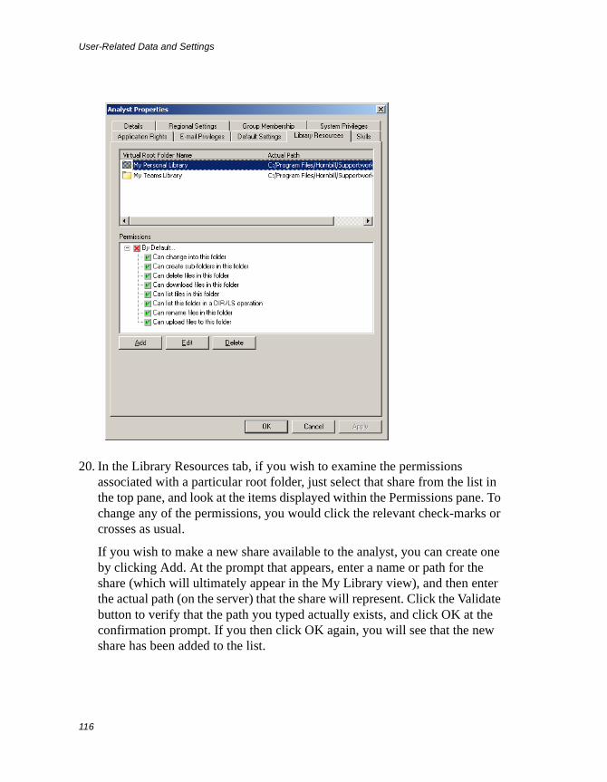
User-Related Data and Settings
116
20. In the Library Resources tab, if you wish to examine the permissions associated with a particular root folder, just select that share from the list in the top pane, and look at the items displayed within the Permissions pane. To change any of the permissions, you would click the relevant check-marks or crosses as usual.
If you wish to make a new share available to the analyst, you can create one by clicking Add. At the prompt that appears, enter a name or path for the share (which will ultimately appear in the My Library view), and then enter the actual path (on the server) that the share will represent. Click the Validate button to verify that the path you typed actually exists, and click OK at the confirmation prompt. If you then click OK again, you will see that the new share has been added to the list.
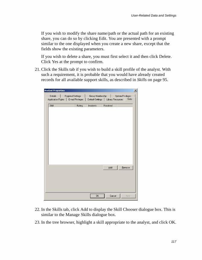
User-Related Data and Settings
117
If you wish to modify the share name/path or the actual path for an existing share, you can do so by clicking Edit. You are presented with a prompt similar to the one displayed when you create a new share, except that the fields show the existing parameters.
If you wish to delete a share, you must first select it and then click Delete. Click Yes at the prompt to confirm.
21. Click the Skills tab if you wish to build a skill profile of the analyst. With such a requirement, it is probable that you would have already created records for all available support skills, as described in Skills on page 95.
22. In the Skills tab, click Add to display the Skill Chooser dialogue box. This is similar to the Manage Skills dialogue box.
23. In the tree browser, highlight a skill appropriate to the analyst, and click OK.
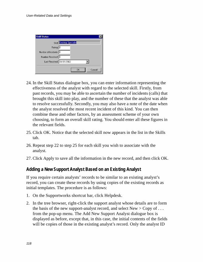
User-Related Data and Settings
118
24. In the Skill Status dialogue box, you can enter information representing the effectiveness of the analyst with regard to the selected skill. Firstly, from past records, you may be able to ascertain the number of incidents (calls) that brought this skill into play, and the number of these that the analyst was able to resolve successfully. Secondly, you may also have a note of the date when the analyst resolved the most recent incident of this kind. You can then combine these and other factors, by an assessment scheme of your own choosing, to form an overall skill rating. You should enter all these figures in the relevant fields.
25. Click OK. Notice that the selected skill now appears in the list in the Skills tab.
26. Repeat step 22 to step 25 for each skill you wish to associate with the analyst.
27. Click Apply to save all the information in the new record, and then click OK.
Adding a New Support Analyst Based on an Existing Analyst
If you require certain analysts’ records to be similar to an existing analyst’s record, you can create these records by using copies of the existing records as initial templates. The procedure is as follows:
1. On the Supportworks shortcut bar, click Helpdesk.
2. In the tree browser, right-click the support analyst whose details are to form the basis of the new support-analyst record, and select New > Copy of . . . from the pop-up menu. The Add New Support Analyst dialogue box is displayed as before, except that, in this case, the initial contents of the fields will be copies of those in the existing analyst’s record. Only the analyst ID
User-Related Data and Settings
119
and name are different, consisting of the original with an underscore and a numeral appended.
3. Complete the required fields in each of the tabs, as described in the main procedure above.
Viewing and Modifying the Details of an Existing Support Analyst
To examine and edit a support-analyst record, follow the instructions given here:
1. On the Supportworks shortcut bar, click Helpdesk.
2. In the tree browser, right-click the support analyst whose details you wish to view or edit, and select Properties from the pop-up menu. The Support Analyst Properties dialogue box is displayed, showing the same tabs as the Add New Support Analyst dialogue box.
3. You can now click any tab and view or edit the contents of its fields.
4. Click Apply to save your changes, and then click OK.
Changing the Availability Status of a Support Analyst
When a support analyst is out of the office for any reason, it is possible to arrange for other members of the team to be notified of the individual’s absence by setting his or her availability status on the system. In most organisations, it would make sense for all analysts to be given the right to set their own availability status.
Normally, the status of an analyst would be “Available”, and no absence notifications would be issued. However, if the Current Availability field in the Details tab is set to anything else, a notification indicating the status would pop up on the desktop of any other team member who tried to assign or transfer a call to the analyst.
In addition to being able to select an appropriate status to indicate absence, you can compose a suitable text message to include in the notification. You do this by means of the Absence Message button, which is located next to the Current Availability field.
User-Related Data and Settings
120
Changing a Password
If you have the appropriate rights, you can change the password of any member of your team or group who uses the “Supportworks Security Database” method of login authentication. With the Details tab displayed, double-click in the first Password field and type the new password. Repeat this in the second Password field and click Apply.
For changing your own password, there is no need to open any dialogue box showing your analyst record. Instead, you can perform the following procedure:
1. From the Tools menu, select Change My Password to display the Change My Password dialogue box.
2. In the Old Password field, enter your current password.
3. In both the New Password and Confirm fields, enter the new password.
4. Click OK.
Your password is suitably updated in the database.
Recovering an Analyst’s Password
If any member of your team or group (using the “Supportworks Security Database” method of login authentication) has forgotten their password, and you have the appropriate rights, you can quickly reset the password to the original default (password) without having to display the analyst’s record. This is known as password recovery. The procedure is as follows:
1. Click the Helpdesk icon in the shortcut bar to display the Helpdesk view.
2. In the tree browser, right-click the relevant Support Analyst and select Recover Password from the pop-up menu. A message is displayed on your desktop confirming that the password has been recovered.
3. Click OK in the confirmation window.
As an alternative to using the Helpdesk view’s tree browser as the place from which to recover a password, you could use the tree browser in the Switch Context window. You access this window by selecting Helpdesk > Switch Context.
User-Related Data and Settings
121
What Needs to Be Done After Changing System Privileges
When you change another analyst’s privileges on the system (using the options in the System Privileges tab), and the analyst is currently logged into the system, the changes will not be noticed until the analyst logs out and then logs back in again. In contrast, when you change your own privileges (assuming you have the authority to do so), you will not need to restart your client session to make the changes manifest.
Removing an Analyst’s Access to a Mailbox
If you have the appropriate rights, you can revoke an analyst’s ability to access a shared mailbox. With the E-Mail Privileges tab displayed, select the mailbox concerned and click Remove Shared Mailbox. The mailbox disappears from the tree browser and, when the analyst next logs in, the relevant icon will no longer be visible in their shortcut bar.
Updating the Details of a Skill in an Analyst’s Skill Profile
If you have the appropriate rights, you can edit the existing information that represents the effectiveness of an analyst with regard to a specific skill. With the Skills tab displayed, double-click the skill concerned to view the Skill Status dialogue box. Modify the data in any of the fields as required, and click OK.
Removing a Skill from an Analyst’s Skill Profile
If you have the appropriate rights, you can remove any skill currently associated with an analyst. With the Skills tab displayed, select the relevant skill and click Remove. Notice that the skill entry has now disappeared from the list.
Deleting an Existing Support Analyst
To delete an analyst record, follow the instructions given here:
1. On the Supportworks shortcut bar, click Helpdesk.
2. In the tree browser, right-click the support analyst you wish to delete, and select Delete from the pop-up menu. Once you have confirmed the proposed action, the record is deleted.
User-Related Data and Settings
122
Analyst Management Capabilities Relating to Each RoleWhether or not you are allowed to create and delete support-analyst and support-group records and, if so, what contexts you can perform these actions in, are governed by the role that has been assigned to you. So, too, are the limits of precisely what you can set or change in such a record.
In the System Administrator role, you will be able to create and delete analyst records of anyone in your organisation’s support team. You will also be able to create and delete support groups. For any analyst record created, you will be able to edit all fields except Analyst ID, adjust all settings, and use all buttons in the Analyst Properties dialogue box.
As a Group Manager, you can create and delete records of only those analysts who belong to your own support group. You will not be able to create or delete any support groups or sub-groups. You can make changes only in your own analyst record and in the records of the analysts in your group. There are, additionally, certain limitations on the actual changes you can make. In the Details tab, you can change everything except the Analyst ID, the Home Group setting and the login authentication. In the System Privileges tab, you can change the role to anything other than System Administrator, but you can change neither the data dictionary nor any of the permissions. In the Default Settings tab, you can modify all settings (although you will not be able to set the allowable profile detail for a member of your group to any level lower than your own).
In the Support Analyst role, you are unable to create or delete any analyst or group records, and you can make changes only in your own analyst record. However, the allowed changes are very limited and are confined to the Details and Regional Settings tabs. The Skills tab is read-only. In the Details tab, you can modify everything except your Analyst ID, your Home Group setting and your login authentication.
Managing E-Mail
123
Managing E-Mail
The Messaging System included with Supportworks is a powerful and flexible e-mail application that may be used in a number of different configurations, depending on the requirements of your helpdesk. It can operate in stand-alone and interconnecting modes, and can integrate intelligently with various aspects of Supportworks functionality.
You can set up the Messaging System to work in one or more of the following ways:
• By default, you have the ability to send e-mail (and quick pop-up messages) internally to any member of the support team whose details are recorded in the Support Analyst tables. You can also receive e-mail (and quick pop-up messages) from these analysts. Every analyst record is associated with a personal mailbox that holds the analyst’s e-mail.
• By configuring and enabling the Internet Mail Connector in the Messaging tab of the Server Configuration utility, and by setting up the relevant mailboxes in the System Mailboxes tab, you can integrate the Messaging System with any other mail system in your organisation, provided that it supports SMTP/POP3/IMAP4 Internet mail (which would therefore include Microsoft Exchange and Lotus Notes). With such a configuration, analysts should be able to send e-mail to recipients registered in the other mail environment and also over the Internet. In addition, they can be allowed access to one or more shared mailboxes so that they can handle inbound mail collectively as a group. However, analysts would not be able to receive external e-mail in their personal mailboxes via the Internet Mail Connector (therefore see the last point below).
• By configuring and enabling the Exchange Mail Connector, you can integrate the Messaging System with any Microsoft Exchange mail system used in your organisation, particularly if it is not connected to the Internet. Such a configuration would allow analysts access to only one shared mailbox. This option is not available on Supportworks Essentials systems.
• By configuring and enabling the Notes Mail Connector, you can integrate the Messaging System with any Lotus Notes mail system used in your
Managing E-Mail
124
organisation, particularly if it is not connected to the Internet. Such a configuration would allow analysts access to only one shared mailbox. This option is not available on Supportworks Essentials systems.
• By registering one or more Internet domains for your helpdesk, and then setting up a dedicated SMTP mail server for the Messaging System via the Inbound SMTP Mail Routing tab of the Server Configuration utility, you can allow Internet e-mail to be received by analysts in their personal mailboxes as well as in their shared mailboxes.
All global aspects of e-mail setup, as mentioned in the above bullet points, are covered in the Server Configuration Guide. Actual e-mail usage is detailed in the ESP User Guide. This chapter of the Administrator Guide covers specific aspects of e-mail that are usually regarded as management functions. They include managing address books, managing templates (for mail merge) and sending bulk mailshots.
Managing Address BooksAn address book, in the context of Supportworks e-mail, is a database of records containing the display name and e-mail address of every known customer, every member of the support team, and every other contact to whom you may wish to send mail. It can also contain named distribution lists of multiple contacts. A number of separate address books, all located on the Supportworks server, are accessible to you from the client:
• The Global Address Book This can contain address data from a number of different sources. Firstly, data can be obtained from various internal databases and Exchange/Notes imports, and this is re-built automatically on a daily basis to include the latest additions. Addresses can also be obtained from incoming mail by means of an automatic learning mechanism. In addition, if you are suitably authorised, you can manually create (and possibly modify and delete) entries in this address book on a selective basis, or you can manually import addresses in bulk from Microsoft Outlook. The addresses held in the Global Address Book are available to all members of the support team.
• Shared mailbox address books Each shared mailbox on the system has a specific address book associated with it. If you have access to a given
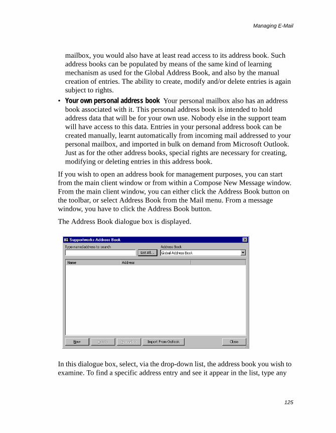
Managing E-Mail
125
mailbox, you would also have at least read access to its address book. Such address books can be populated by means of the same kind of learning mechanism as used for the Global Address Book, and also by the manual creation of entries. The ability to create, modify and/or delete entries is again subject to rights.
• Your own personal address book Your personal mailbox also has an address book associated with it. This personal address book is intended to hold address data that will be for your own use. Nobody else in the support team will have access to this data. Entries in your personal address book can be created manually, learnt automatically from incoming mail addressed to your personal mailbox, and imported in bulk on demand from Microsoft Outlook. Just as for the other address books, special rights are necessary for creating, modifying or deleting entries in this address book.
If you wish to open an address book for management purposes, you can start from the main client window or from within a Compose New Message window. From the main client window, you can either click the Address Book button on the toolbar, or select Address Book from the Mail menu. From a message window, you have to click the Address Book button.
The Address Book dialogue box is displayed.
In this dialogue box, select, via the drop-down list, the address book you wish to examine. To find a specific address entry and see it appear in the list, type any
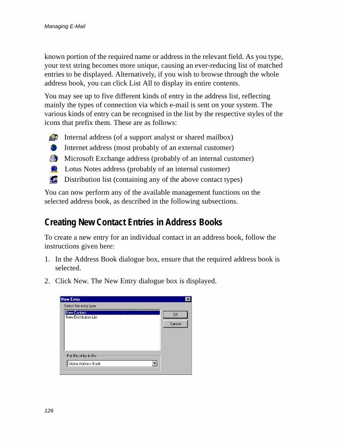
Managing E-Mail
126
known portion of the required name or address in the relevant field. As you type, your text string becomes more unique, causing an ever-reducing list of matched entries to be displayed. Alternatively, if you wish to browse through the whole address book, you can click List All to display its entire contents.
You may see up to five different kinds of entry in the address list, reflecting mainly the types of connection via which e-mail is sent on your system. The various kinds of entry can be recognised in the list by the respective styles of the icons that prefix them. These are as follows:
Internal address (of a support analyst or shared mailbox)
Internet address (most probably of an external customer)
Microsoft Exchange address (probably of an internal customer)
Lotus Notes address (probably of an internal customer)
Distribution list (containing any of the above contact types)
You can now perform any of the available management functions on the selected address book, as described in the following subsections.
Creating New Contact Entries in Address Books
To create a new entry for an individual contact in an address book, follow the instructions given here:
1. In the Address Book dialogue box, ensure that the required address book is selected.
2. Click New. The New Entry dialogue box is displayed.
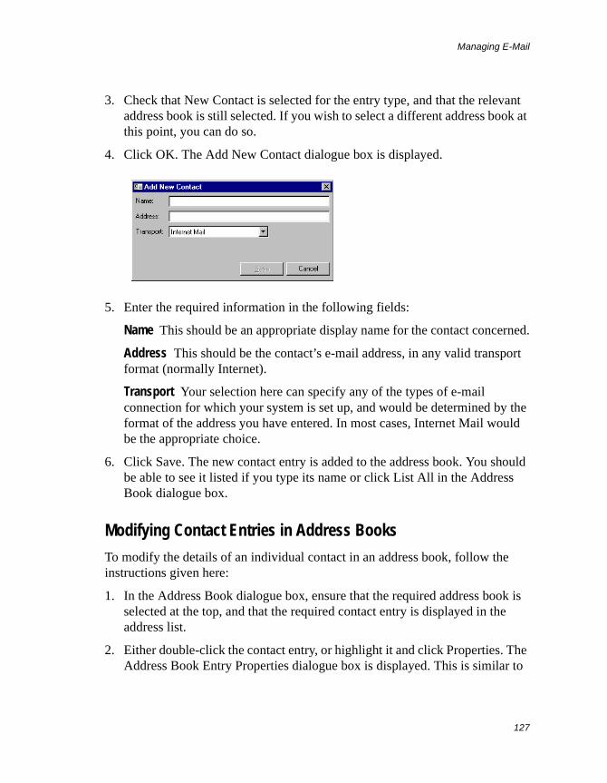
Managing E-Mail
127
3. Check that New Contact is selected for the entry type, and that the relevant address book is still selected. If you wish to select a different address book at this point, you can do so.
4. Click OK. The Add New Contact dialogue box is displayed.
5. Enter the required information in the following fields:
Name This should be an appropriate display name for the contact concerned.
Address This should be the contact’s e-mail address, in any valid transport format (normally Internet).
Transport Your selection here can specify any of the types of e-mail connection for which your system is set up, and would be determined by the format of the address you have entered. In most cases, Internet Mail would be the appropriate choice.
6. Click Save. The new contact entry is added to the address book. You should be able to see it listed if you type its name or click List All in the Address Book dialogue box.
Modifying Contact Entries in Address Books
To modify the details of an individual contact in an address book, follow the instructions given here:
1. In the Address Book dialogue box, ensure that the required address book is selected at the top, and that the required contact entry is displayed in the address list.
2. Either double-click the contact entry, or highlight it and click Properties. The Address Book Entry Properties dialogue box is displayed. This is similar to
Managing E-Mail
128
the Add New Contact dialogue box that appears when you are creating a distribution list. It displays the details of the selected contact.
3. Make the necessary changes to the relevant field(s) and click OK. The entry is now updated.
Deleting Entries from Address Books
To delete one or more contacts and/or distribution lists from an address book, follow the instructions given here:
1. In the Address Book dialogue box, ensure that the required address book is selected at the top, and that the first (or only) required contact entry is displayed in the address list.
2. Highlight the required entries by multiple selection (or just the required entry) and click Delete.
3. At the confirmation prompt, click Yes. The entries (or the single entry) would now be deleted from the address book.
Managing Distribution Lists in Address Books
A distribution list is a named address-book entry that represents a defined collection of contacts. When you address a message to a distribution list, it will be sent to each and every contact defined in that list.
Supportworks provides facilities to create, examine, update and delete distribution lists.
Creating a New Distribution List
To create an entry for a distribution list in an address book, follow the instructions given here:
1. In the Address Book dialogue box, ensure that the address book in which you wish to create the distribution list is selected.
2. Click New. The New Entry dialogue box is displayed.
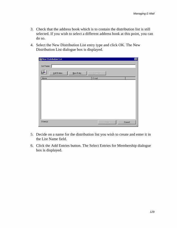
Managing E-Mail
129
3. Check that the address book which is to contain the distribution list is still selected. If you wish to select a different address book at this point, you can do so.
4. Select the New Distribution List entry type and click OK. The New Distribution List dialogue box is displayed.
5. Decide on a name for the distribution list you wish to create and enter it in the List Name field.
6. Click the Add Entries button. The Select Entries for Membership dialogue box is displayed.
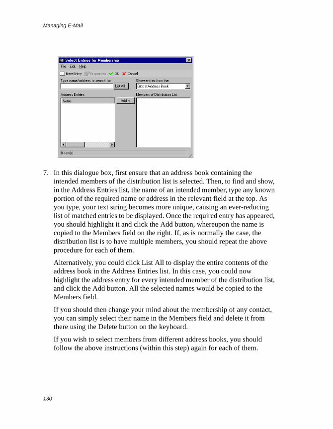
Managing E-Mail
130
7. In this dialogue box, first ensure that an address book containing the intended members of the distribution list is selected. Then, to find and show, in the Address Entries list, the name of an intended member, type any known portion of the required name or address in the relevant field at the top. As you type, your text string becomes more unique, causing an ever-reducing list of matched entries to be displayed. Once the required entry has appeared, you should highlight it and click the Add button, whereupon the name is copied to the Members field on the right. If, as is normally the case, the distribution list is to have multiple members, you should repeat the above procedure for each of them.
Alternatively, you could click List All to display the entire contents of the address book in the Address Entries list. In this case, you could now highlight the address entry for every intended member of the distribution list, and click the Add button. All the selected names would be copied to the Members field.
If you should then change your mind about the membership of any contact, you can simply select their name in the Members field and delete it from there using the Delete button on the keyboard.
If you wish to select members from different address books, you should follow the above instructions (within this step) again for each of them.
Managing E-Mail
131
Once you are satisfied with the make-up of the distribution list, you should click OK. The dialogue box closes, and the contact names appear in the New Distribution List dialogue box.
8. In the New Distribution List dialogue box, click Save. The new entry is added to the originally selected address book. You should be able to see it listed if you type its name or click List All in the Address Book dialogue box.
Hint You can define not only individual contacts, but also other distribution lists, as members of any given distribution list.
Examining and Modifying the Contents of a Distribution List
To view the members of a distribution list in a particular address book, and to add more of them or remove any of them, follow the instructions given here:
1. In the Address Book dialogue box, ensure that the address book containing the required distribution list is selected at the top, and that the required distribution-list entry is displayed in the address list.
2. Either double-click the distribution-list entry, or highlight it and click Properties. The Distribution List dialogue box is displayed. This is similar to the New Distribution List dialogue box that appears when you are creating a distribution list. It displays the current members of the selected list.
3. To add other members to the distribution list, click Add Entries. This displays the Select Entries for Membership dialogue box. Proceed as in step 7 in the subsection Creating a New Distribution List above.
4. To remove a member from the distribution list, highlight its entry in that list and click Remove.
5. Click Save to store the changes you have made to the distribution list.
Importing Addresses from Microsoft Outlook
If you also use Microsoft Outlook as your e-mail client, and you need to be able to send messages from your Supportworks environment to the recipients listed in your Outlook Personal Address Book, you can easily make these addresses
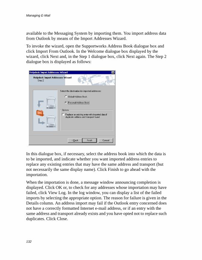
Managing E-Mail
132
available to the Messaging System by importing them. You import address data from Outlook by means of the Import Addresses Wizard.
To invoke the wizard, open the Supportworks Address Book dialogue box and click Import From Outlook. In the Welcome dialogue box displayed by the wizard, click Next and, in the Step 1 dialogue box, click Next again. The Step 2 dialogue box is displayed as follows:
In this dialogue box, if necessary, select the address book into which the data is to be imported, and indicate whether you want imported address entries to replace any existing entries that may have the same address and transport (but not necessarily the same display name). Click Finish to go ahead with the importation.
When the importation is done, a message window announcing completion is displayed. Click OK or, to check for any addresses whose importation may have failed, click View Log. In the log window, you can display a list of the failed imports by selecting the appropriate option. The reason for failure is given in the Details column. An address import may fail if the Outlook entry concerned does not have a correctly formatted Internet e-mail address, or if an entry with the same address and transport already exists and you have opted not to replace such duplicates. Click Close.
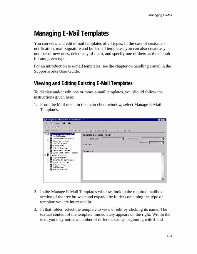
Managing E-Mail
133
Managing E-Mail TemplatesYou can view and edit e-mail templates of all types. In the case of customer-notification, mail-signature and bulk-mail templates, you can also create any number of new ones, delete any of them, and specify one of them as the default for any given type.
For an introduction to e-mail templates, see the chapter on handling e-mail in the Supportworks User Guide.
Viewing and Editing Existing E-Mail Templates
To display and/or edit one or more e-mail templates, you should follow the instructions given here:
1. From the Mail menu in the main client window, select Manage E-Mail Templates.
2. In the Manage E-Mail Templates window, look in the required mailbox section of the tree browser and expand the folder containing the type of template you are interested in.
3. In that folder, select the template to view or edit by clicking its name. The textual content of the template immediately appears on the right. Within the text, you may notice a number of different strings beginning with $ and
Managing E-Mail
134
ending with !. These are macro variables representing data held in the database or “snapshot” data to be generated by the system.
4. In the case of a customer-notificaton template, if you wish to change the call class to which the template is allocated, make the relevant selection in the Call Class field.
5. In the Subject Text and Message Text fields, make any required changes to the e-mail template content. You could edit the text itself, or you could perhaps remove or add variables. The easiest way to insert a variable is by selecting it from the drop-down list next to the Insert Variable button, placing the cursor in the required position in the text and then clicking that button. Alternatively, you could type the name of the variable within the text. See Appendix C: E-mail Template Variables on page 307 for information about template variables, and for definitions of the variables you can use in the templates.
Note that, if HTML is set as the compose-message format (in Tools > Options and Settings > E-mail), you will be able to use, on the message text, any of the Web-style formatting functions available in the Format menu and on the formatting toolbar, just as in e-mail messages composed using Microsoft Outlook. You can temporarily override the default format by selecting either Plain Text or HTML Editor in the Format menu.
6. When you have finished editing the currently displayed template, click the Save Changes button on the toolbar.
7. Repeat the above for each of the templates you wish to modify.
8. Close the Manage E-Mail Templates window.
Creating New E-Mail Templates
If any of the customer-notification e-mail templates provided with Supportworks are totally unsuitable for your purposes, or you need to have more variants of certain of the template types, or perhaps mail-signature or bulk-mail templates are required, you can create multiple new ones of your own design.
To create a new template, follow the instructions given here:
1. From the Mail menu in the main client window, select Manage E-Mail Templates.
Managing E-Mail
135
2. In the Manage E-Mail Templates window, look in the required mailbox section of the tree browser and highlight the folder that is to contain the template you wish to create.
3. Right-click that folder and select Add New from the pop-up menu.
4. At the prompt now displayed, enter a name for the new template and click OK.
5. If you now expand the highlighted folder, you will see the name of the template you just created. Initially, the template will be empty, but once you have selected it, you will be able to enter any required text and variables in the normal way. Also, if this is a customer-notification template, and you need to associate it with a particular call class, you can select that in the Call Class field. If it is a customer-notification or bulk-mail template, you should select a suitable Remote Query for it to use. For a customer notification, the Remote Query to select would normally be Call.
6. When you are satisfied with the content of the template, click the Save Changes button on the toolbar.
7. Close the Manage E-Mail Templates window.
Deleting E-Mail Templates
You can delete any e-mail templates that are of the customer-notification, mail-signature or bulk-mail type. To delete such a template, follow the instructions given here:
1. From the Mail menu in the main client window, select Manage E-Mail Templates.
2. In the Manage E-Mail Templates window, look in the required mailbox section of the tree browser and expand the folder containing the template you wish to delete.
3. Right-click the template and select Delete from the pop-up menu.
4. At the prompt now displayed, click Yes to confirm the deletion. Notice that, as the template is deleted, its name disappears from the tree browser.
5. Close the Manage E-Mail Templates window.
Managing E-Mail
136
Setting a Default E-Mail Template
Within any of the customer-notification and mail-signature e-mail template folders (as displayed in the Manage E-Mail Templates browser), there may be multiple template variants of which you perhaps only use one. This would most likely be the case where templates are maintained and provided centrally under shared mailboxes, and each analyst is expected to use the one appropriate to their own area of responsibility. In such a situation, you can specify a default template for yourself.
You can set one default per template type, and this would apply across all mailboxes (both personal and shared). If you specify a default template for any of the customer-notification template types, that template will be applied automatically at the relevant call-action time (assuming you have requested an e-mail), and you will no longer be prompted for a template. If you specify a default mail-signature template, that template will be applied automatically whenever you open the mail window to compose a new message, but you will still be able to select any alternative mail signature from the usual menu.
To set a template as the default for a particular type, follow the instructions given here:
1. From the Mail menu in the main client window, select Manage E-Mail Templates.
2. In the Manage E-Mail Templates window, look in the required mailbox section of the tree browser and expand the folder containing the type of template you wish to set a default for.
3. In that folder, find the template you wish to specify as the default, right-click its name and select Set As Default from the menu that pops up. A red spot appears on the template’s icon, indicating that this is now the default.
4. Close the Manage E-Mail Templates window.
Once you have set a default for any given type of template, you are free to change it at any time. Alternatively, you can, if you wish, revert to the original situation of not having a default specified at all for that template type. You perform such a reversion by selecting Clear Default from the menu that pops up when you right-click the default template concerned.
Managing E-Mail
137
Sending Bulk MailshotsSupportworks provides a bulk-mailshot feature that allows you to send template-based mail to all your customers whenever you wish to make a general announcement.
If a Remote Query and a set of templates have been created for bulk mail, and you have e-mail template usage rights for the mailbox concerned, you can send any one of a number of bulk mailshots to your customers. Template creation is covered in the subsection entitled Creating New E-Mail Templates on page 134. For information on how to create Remote Queries, please refer to the relevant chapter in the System Customisation Guide.
To send a mailshot, select, from the Mail menu, New Bulk Mail and then the relevant mailbox, followed by the required bulk-mail template. A window similar to the following is displayed:
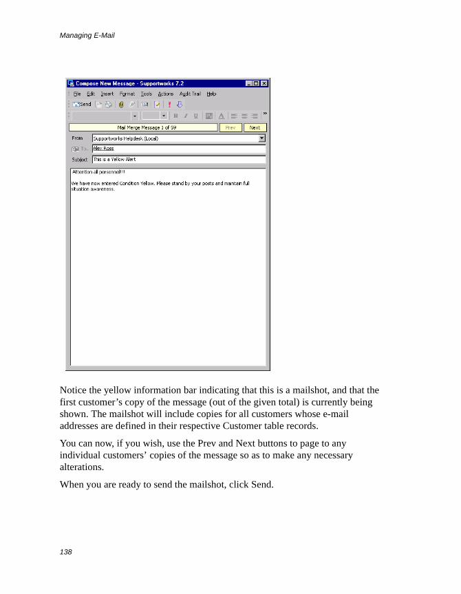
Managing E-Mail
138
Notice the yellow information bar indicating that this is a mailshot, and that the first customer’s copy of the message (out of the given total) is currently being shown. The mailshot will include copies for all customers whose e-mail addresses are defined in their respective Customer table records.
You can now, if you wish, use the Prev and Next buttons to page to any individual customers’ copies of the message so as to make any necessary alterations.
When you are ready to send the mailshot, click Send.
Managing Custom SQL Database Searches
139
Managing Custom SQL Database Searches
As indicated in the User Guide, there are a number of views in the Supportworks client that contain facilities for searching through various database tables. With most of these views, any search you conduct would be through a table that relates specifically to the view concerned, and filtering of the results is limited by what you can specify in the search fields provided.
The Database Searches view, however, gives you the flexibility to create, using SQL statements, custom searches of any of the Supportworks tables. It also allows you to subsequently edit and delete these searches. Your collection of named searches would be visible in a list, from which you can select one at any time to run or to manage.
Information on running such searches is given in the User Guide. The three sections below tell you how to use each of the management functions associated with searches.
Creating a Custom SearchTo create a custom search, follow the instructions given here:
1. Either click the Database Searches icon on the shortcut bar or select Build/Run Database Searches from the Search menu. The Database Searches view is displayed.
2. In the Custom Search Manager pane, click New. The Custom SQL Search Properties dialogue box is displayed.
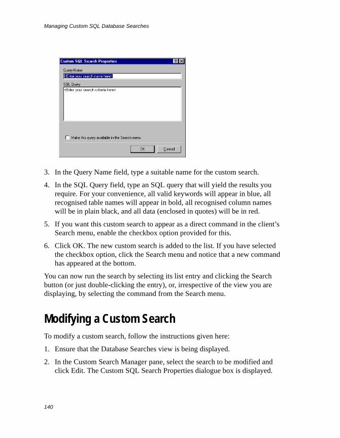
Managing Custom SQL Database Searches
140
3. In the Query Name field, type a suitable name for the custom search.
4. In the SQL Query field, type an SQL query that will yield the results you require. For your convenience, all valid keywords will appear in blue, all recognised table names will appear in bold, all recognised column names will be in plain black, and all data (enclosed in quotes) will be in red.
5. If you want this custom search to appear as a direct command in the client’s Search menu, enable the checkbox option provided for this.
6. Click OK. The new custom search is added to the list. If you have selected the checkbox option, click the Search menu and notice that a new command has appeared at the bottom.
You can now run the search by selecting its list entry and clicking the Search button (or just double-clicking the entry), or, irrespective of the view you are displaying, by selecting the command from the Search menu.
Modifying a Custom SearchTo modify a custom search, follow the instructions given here:
1. Ensure that the Database Searches view is being displayed.
2. In the Custom Search Manager pane, select the search to be modified and click Edit. The Custom SQL Search Properties dialogue box is displayed.
Managing Custom SQL Database Searches
141
3. Make the necessary changes.
4. Click OK.
Deleting a Custom SearchTo delete a custom search, first ensure that the Database Searches view is being displayed. Then select the relevant search and click Delete. No confirmation prompt is given, and the entry immediately disappears from the list.

Managing Custom SQL Database Searches
142
Managing the KnowledgeBase
143
Managing the KnowledgeBase
As indicated in the chapter of the Server Configuration Guide that covers the KnowledgeBase, and in the section of the User Guide that describes the KnowledgeBase view, the KnowledgeBase is a repository of records and documents in which support analysts and customers can look up information concerning problems (together with their fixes) that have already been encountered by your helpdesk, or access any other pertinent information. The contents of the KnowledgeBase can be any of the following:
• Problem and resolution data derived from resolved or closed calls, but probably edited (either at the time of call resolution/closure or later)
• Manually entered FAQ data, stored in the same record format as the data derived from calls
• Imported external documents, in various formats, attached to manually created header records
• Records that point to the Supportworks on-line user documents
By default, each one of these content types is held in its own, separate catalogue within the KnowledgeBase. However, it is possible to create new catalogues and save KnowledgeBase data to those as well, and you can move data between catalogues.
Placing Content into the KnowledgeBaseThere are three ways in which you can publish information in the KnowledgeBase, depending on the nature of the data concerned. These methods are described in the following subsections.
How to Publish Call Information
It is possible to submit data from any given call to the KnowledgeBase either immediately after resolving or closing the call, or at some later time. The means
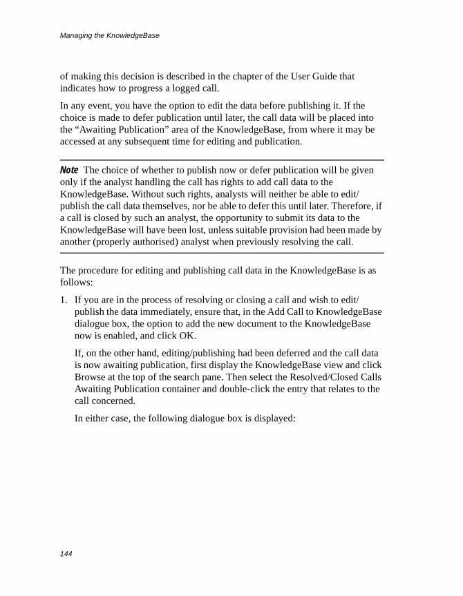
Managing the KnowledgeBase
144
of making this decision is described in the chapter of the User Guide that indicates how to progress a logged call.
In any event, you have the option to edit the data before publishing it. If the choice is made to defer publication until later, the call data will be placed into the “Awaiting Publication” area of the KnowledgeBase, from where it may be accessed at any subsequent time for editing and publication.
Note The choice of whether to publish now or defer publication will be given only if the analyst handling the call has rights to add call data to the KnowledgeBase. Without such rights, analysts will neither be able to edit/publish the call data themselves, nor be able to defer this until later. Therefore, if a call is closed by such an analyst, the opportunity to submit its data to the KnowledgeBase will have been lost, unless suitable provision had been made by another (properly authorised) analyst when previously resolving the call.
The procedure for editing and publishing call data in the KnowledgeBase is as follows:
1. If you are in the process of resolving or closing a call and wish to edit/publish the data immediately, ensure that, in the Add Call to KnowledgeBase dialogue box, the option to add the new document to the KnowledgeBase now is enabled, and click OK.
If, on the other hand, editing/publishing had been deferred and the call data is now awaiting publication, first display the KnowledgeBase view and click Browse at the top of the search pane. Then select the Resolved/Closed Calls Awaiting Publication container and double-click the entry that relates to the call concerned.
In either case, the following dialogue box is displayed:
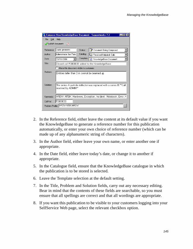
Managing the KnowledgeBase
145
2. In the Reference field, either leave the content at its default value if you want the KnowledgeBase to generate a reference number for this publication automatically, or enter your own choice of reference number (which can be made up of any alphanumeric string of characters).
3. In the Author field, either leave your own name, or enter another one if appropriate.
4. In the Date field, either leave today’s date, or change it to another if appropriate.
5. In the Catalogue field, ensure that the KnowledgeBase catalogue in which the publication is to be stored is selected.
6. Leave the Template selection at the default setting.
7. In the Title, Problem and Solution fields, carry out any necessary editing. Bear in mind that the contents of these fields are searchable, so you must ensure that all spellings are correct and that all wordings are appropriate.
8. If you want this publication to be visible to your customers logging into your SelfService Web page, select the relevant checkbox option.
Managing the KnowledgeBase
146
9. Notice the problem- and resolution-profile elements that have been generated in the Keywords field, separated from each other by a comma and a space. The contents of this field are also searchable. If you wish, you can add to this list any extra words that you think may be equally representative of the content of this publication. Likewise, you may delete words from the list.
10. The contents of the Call Ref and Problem Profile Code fields would normally stay as they are. However, you can change them if necessary.
11. If you want to close the dialogue box but have not yet finished making changes, ensure that Document Being Composed is selected in the Status field.
However, if you have finished making changes but the content has not yet been checked by the relevant people, set the status to Document Awaiting Approval.
Alternatively, if you have finished making changes and the content has now been checked (or there is no need for checking), set the status to Document Approved for Publishing.
12. Click Publish Document on the toolbar.
Irrespective of what status you have set, a copy of the publication is now created and placed in the Resolved Helpdesk Calls catalogue of the KnowledgeBase (or whichever catalogue you have chosen). The relevant entry in the Resolved/Closed Calls Awaiting Publication container is nevertheless retained, and will remain there until you delete it.
When a publication derived from a call is opened by an analyst (from the search-results list or browse list in the KnowledgeBase view), it is displayed in the analyst’s Web browser as follows:
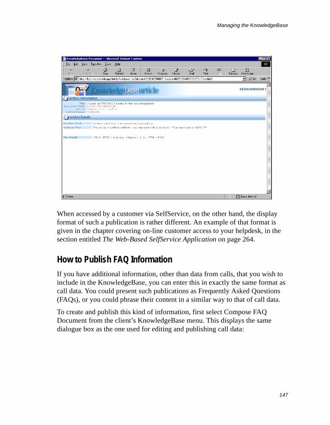
Managing the KnowledgeBase
147
When accessed by a customer via SelfService, on the other hand, the display format of such a publication is rather different. An example of that format is given in the chapter covering on-line customer access to your helpdesk, in the section entitled The Web-Based SelfService Application on page 264.
How to Publish FAQ Information
If you have additional information, other than data from calls, that you wish to include in the KnowledgeBase, you can enter this in exactly the same format as call data. You could present such publications as Frequently Asked Questions (FAQs), or you could phrase their content in a similar way to that of call data.
To create and publish this kind of information, first select Compose FAQ Document from the client’s KnowledgeBase menu. This displays the same dialogue box as the one used for editing and publishing call data:
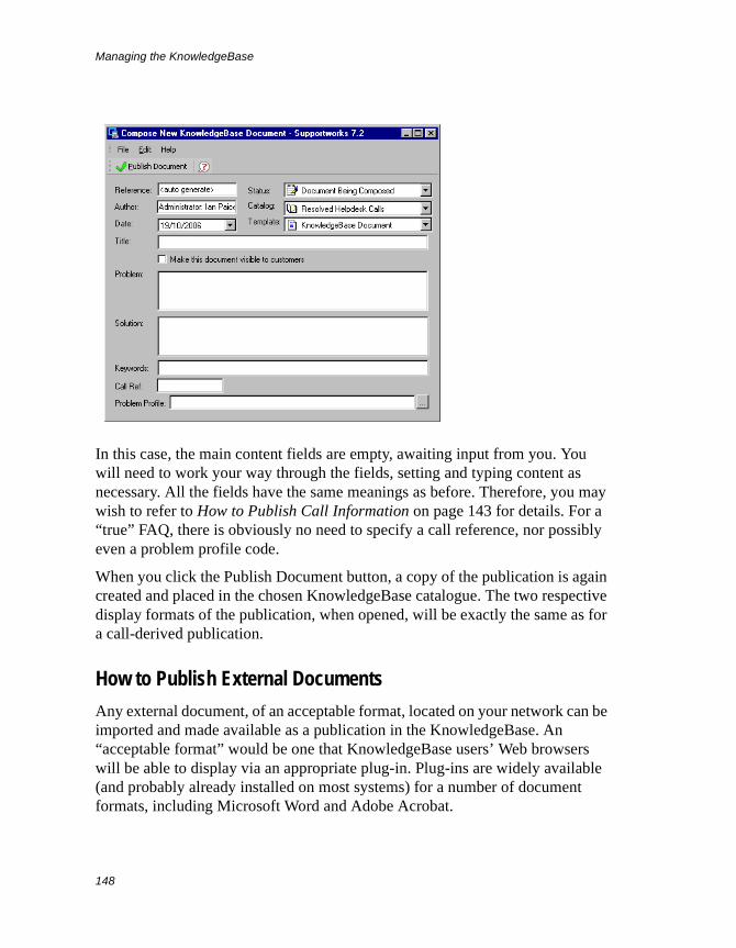
Managing the KnowledgeBase
148
In this case, the main content fields are empty, awaiting input from you. You will need to work your way through the fields, setting and typing content as necessary. All the fields have the same meanings as before. Therefore, you may wish to refer to How to Publish Call Information on page 143 for details. For a “true” FAQ, there is obviously no need to specify a call reference, nor possibly even a problem profile code.
When you click the Publish Document button, a copy of the publication is again created and placed in the chosen KnowledgeBase catalogue. The two respective display formats of the publication, when opened, will be exactly the same as for a call-derived publication.
How to Publish External Documents
Any external document, of an acceptable format, located on your network can be imported and made available as a publication in the KnowledgeBase. An “acceptable format” would be one that KnowledgeBase users’ Web browsers will be able to display via an appropriate plug-in. Plug-ins are widely available (and probably already installed on most systems) for a number of document formats, including Microsoft Word and Adobe Acrobat.
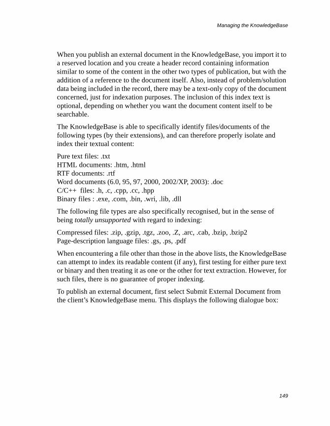
Managing the KnowledgeBase
149
When you publish an external document in the KnowledgeBase, you import it to a reserved location and you create a header record containing information similar to some of the content in the other two types of publication, but with the addition of a reference to the document itself. Also, instead of problem/solution data being included in the record, there may be a text-only copy of the document concerned, just for indexation purposes. The inclusion of this index text is optional, depending on whether you want the document content itself to be searchable.
The KnowledgeBase is able to specifically identify files/documents of the following types (by their extensions), and can therefore properly isolate and index their textual content:
Pure text files: .txtHTML documents: .htm, .htmlRTF documents: .rtfWord documents (6.0, 95, 97, 2000, 2002/XP, 2003): .docC/C++ files: .h, .c, .cpp, .cc, .hppBinary files : .exe, .com, .bin, .wri, .lib, .dll
The following file types are also specifically recognised, but in the sense of being totally unsupported with regard to indexing:
Compressed files: .zip, .gzip, .tgz, .zoo, .Z, .arc, .cab, .bzip, .bzip2Page-description language files: .gs, .ps, .pdf
When encountering a file other than those in the above lists, the KnowledgeBase can attempt to index its readable content (if any), first testing for either pure text or binary and then treating it as one or the other for text extraction. However, for such files, there is no guarantee of proper indexing.
To publish an external document, first select Submit External Document from the client’s KnowledgeBase menu. This displays the following dialogue box:
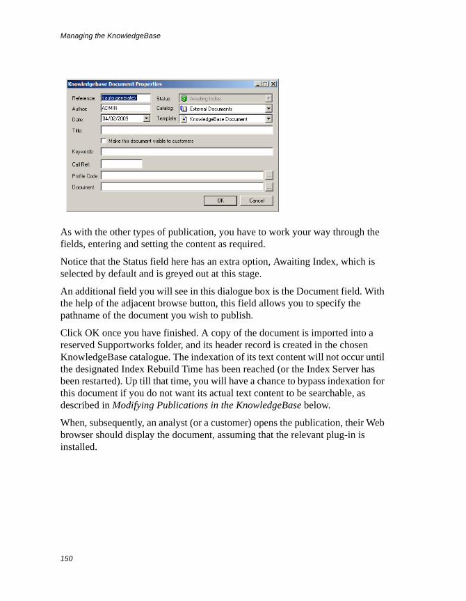
Managing the KnowledgeBase
150
As with the other types of publication, you have to work your way through the fields, entering and setting the content as required.
Notice that the Status field here has an extra option, Awaiting Index, which is selected by default and is greyed out at this stage.
An additional field you will see in this dialogue box is the Document field. With the help of the adjacent browse button, this field allows you to specify the pathname of the document you wish to publish.
Click OK once you have finished. A copy of the document is imported into a reserved Supportworks folder, and its header record is created in the chosen KnowledgeBase catalogue. The indexation of its text content will not occur until the designated Index Rebuild Time has been reached (or the Index Server has been restarted). Up till that time, you will have a chance to bypass indexation for this document if you do not want its actual text content to be searchable, as described in Modifying Publications in the KnowledgeBase below.
When, subsequently, an analyst (or a customer) opens the publication, their Web browser should display the document, assuming that the relevant plug-in is installed.
Managing the KnowledgeBase
151
Modifying Publications in the KnowledgeBaseOnce you have published an item of information in the KnowledgeBase, irrespective of which status you have set for it, you can return to it at any time to make modifications.
To amend a publication, first display the KnowledgeBase view and either conduct a search for the publication or use the browse facilities to find it. Then right-click its entry in the right-hand pane and select Properties from the menu that pops up. The same dialogue box as the one used to publish the item in the first place is now displayed, and you are free to modify any of the fields. For example, to move an item to another catalogue, you would change the selection in the Catalogue field and then click the Save Changes button.
Notice that, for an external document, the Status option is now modifiable. If you have only just published such a document and want to exclude its text from all KnowledgeBase searches, you must change its status from Awaiting Index to any of the others. Remember that performing this action will bypass indexation of the document only if you do it prior to reaching the Index Rebuild Time (or restarting the Index Server) for the first time after publishing the document.
If you have opted to bypass indexation, you must pay particular attention to the Keywords field, as KnowledgeBase searches will then not look at text in the actual body of the external document
Deleting Publications from the KnowledgeBaseYou can delete any of the items you have published in the KnowledgeBase, and you can also delete items that are awaiting publication. When you delete published items, they are not deleted completely, but are removed from the searchable area and placed into a “recycle bin” type of container called Deleted KnowledgeBase Documents. However, when you delete items still to be published, they disappear altogether and cannot be subsequently restored.
To delete a published item or a group of these, first display the KnowledgeBase view and either conduct a search for the items or use the browse facilities to find them. Then select the entries in the right-hand pane, right-click your selection and select Delete Document from the menu that pops up. Finally, click Yes at
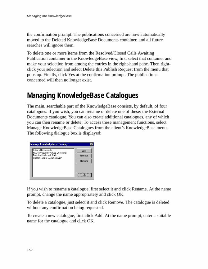
Managing the KnowledgeBase
152
the confirmation prompt. The publications concerned are now automatically moved to the Deleted KnowledgeBase Documents container, and all future searches will ignore them.
To delete one or more items from the Resolved/Closed Calls Awaiting Publication container in the KnowledgeBase view, first select that container and make your selection from among the entries in the right-hand pane. Then right-click your selection and select Delete this Publish Request from the menu that pops up. Finally, click Yes at the confirmation prompt. The publications concerned will then no longer exist.
Managing KnowledgeBase CataloguesThe main, searchable part of the KnowledgeBase consists, by default, of four catalogues. If you wish, you can rename or delete one of these: the External Documents catalogue. You can also create additional catalogues, any of which you can then rename or delete. To access these management functions, select Manage KnowledgeBase Catalogues from the client’s KnowledgeBase menu. The following dialogue box is displayed:
If you wish to rename a catalogue, first select it and click Rename. At the name prompt, change the name appropriately and click OK.
To delete a catalogue, just select it and click Remove. The catalogue is deleted without any confirmation being requested.
To create a new catalogue, first click Add. At the name prompt, enter a suitable name for the catalogue and click OK.
Managing Calendars
153
Managing Calendars
Supportworks calendars are used for storing and displaying appointments involving one or more support analysts, customers and/or non-human resources. A calendar can belong to a support analyst, to a group of support analysts, or to a non-human resource. Whenever a new analyst record is created, a personal calendar for that individual is automatically created along with it. However, each group of analysts working together who require the use of a shared calendar would need to have one created manually for them. Likewise, each non-human resource whose availability needs to be tracked would require a resource calendar to be created.
Management functions are provided that allow you to create calendars as necessary. Since calendars have various configurable properties, the management functions also allow you to set those. The properties of a calendar are as follows:
• Working hours
• Identifying details
• Specification of the analysts having rights to the calendar
• Specification of these rights
Creating a CalendarIf you are authorised to do so, you can create shared and resource calendars manually by means of the calendar-management facilities. You can also create personal calendars, although you will not need to do this manually unless the Calendar Server was not running when a given analyst record was created.
To create a calendar, follow the instructions given here:
1. Select Manage Calendars from the Administration menu on the main client window.
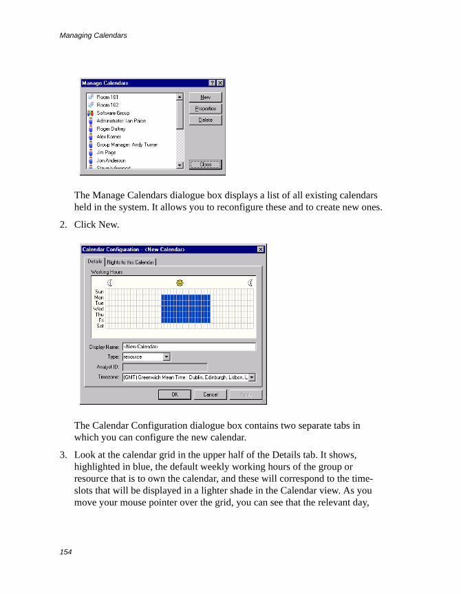
Managing Calendars
154
The Manage Calendars dialogue box displays a list of all existing calendars held in the system. It allows you to reconfigure these and to create new ones.
2. Click New.
The Calendar Configuration dialogue box contains two separate tabs in which you can configure the new calendar.
3. Look at the calendar grid in the upper half of the Details tab. It shows, highlighted in blue, the default weekly working hours of the group or resource that is to own the calendar, and these will correspond to the time-slots that will be displayed in a lighter shade in the Calendar view. As you move your mouse pointer over the grid, you can see that the relevant day,
Managing Calendars
155
and the range of working hours for that day, are displayed at the bottom left of the calendar, and the day and the start of the half-hour time-slot represented by the cell you are pointing at are displayed at the bottom right. If you see that the default days and hours are in accordance with the requirements of this calendar, you should skip the following four steps.
4. To set the working hours (to the nearest half-hour) for any given day of the week, first clear the existing range (if any) by clicking any cell within that day, and then move the mouse pointer to the desired work-start time for that day. Alternatively, if you just want to adjust the start or end time of a working day, move the mouse pointer over to the start or end cell for that day.
5. Click the left mouse button and hold it down while dragging the mouse pointer to the desired end (or start) time of the working day. As you drag the pointer, a tooltip appears, showing you the time range you are setting.
6. Release the mouse button. The new duration of the relevant day will now be highlighted in blue.
7. Repeat step 4 to step 6 for each day you wish to set. To remove the time range for a day that is not to be a working day, just single-click any cell for that day.
8. In the Display Name field, enter a suitable name for the calendar.
9. In the Type field, select the calendar type.
10. If you are creating a personal calendar, enter, in the Analyst ID field, the ID of the analyst to whom the calendar will belong.
11. Ensure that an appropriate time zone is selected. For a personal calendar, this should be the same as the time zone held in the relevant analyst’s record. For a shared or resource calendar, the time zone should again be the one that applies to the region where the participants in appointments expected to be set up in that calendar are located.
12. Click the Rights to this Calendar tab.
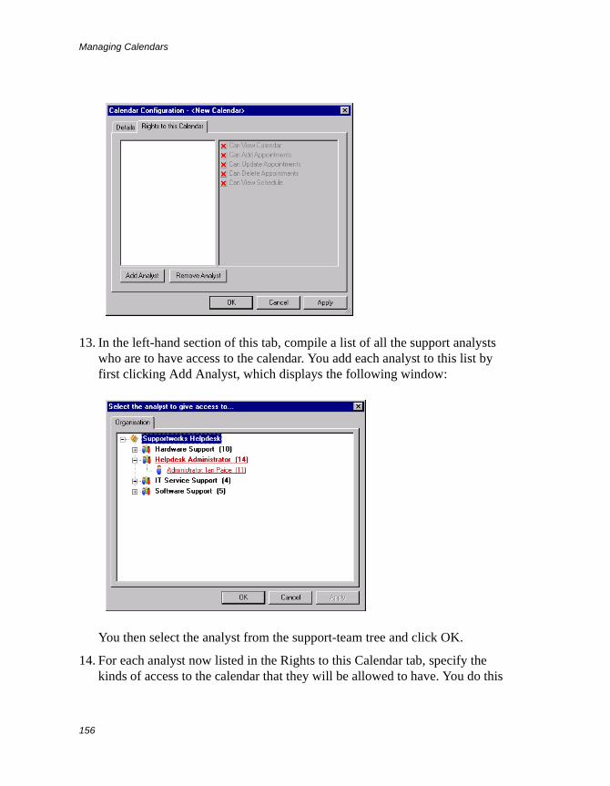
Managing Calendars
156
13. In the left-hand section of this tab, compile a list of all the support analysts who are to have access to the calendar. You add each analyst to this list by first clicking Add Analyst, which displays the following window:
You then select the analyst from the support-team tree and click OK.
14. For each analyst now listed in the Rights to this Calendar tab, specify the kinds of access to the calendar that they will be allowed to have. You do this
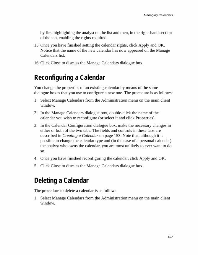
Managing Calendars
157
by first highlighting the analyst on the list and then, in the right-hand section of the tab, enabling the rights required.
15. Once you have finished setting the calendar rights, click Apply and OK. Notice that the name of the new calendar has now appeared on the Manage Calendars list.
16. Click Close to dismiss the Manage Calendars dialogue box.
Reconfiguring a CalendarYou change the properties of an existing calendar by means of the same dialogue boxes that you use to configure a new one. The procedure is as follows:
1. Select Manage Calendars from the Administration menu on the main client window.
2. In the Manage Calendars dialogue box, double-click the name of the calendar you wish to reconfigure (or select it and click Properties).
3. In the Calendar Configuration dialogue box, make the necessary changes in either or both of the two tabs. The fields and controls in these tabs are described in Creating a Calendar on page 153. Note that, although it is possible to change the calendar type and (in the case of a personal calendar) the analyst who owns the calendar, you are most unlikely to ever want to do so.
4. Once you have finished reconfiguring the calendar, click Apply and OK.
5. Click Close to dismiss the Manage Calendars dialogue box.
Deleting a CalendarThe procedure to delete a calendar is as follows:
1. Select Manage Calendars from the Administration menu on the main client window.
Managing Calendars
158
2. In the Manage Calendars dialogue box, select the name of the calendar you wish to delete and click Delete. Notice that the calendar you have chosen has now disappeared from the list.
3. Click Close to dismiss the Manage Calendars dialogue box.
Management Information and Reporting
159
Management Information and Reporting
Reports in Supportworks are organised arrangements of largely management information whose value elements are obtained from the records of appropriate tables in the Supportworks database. Supportworks has facilities by which you can display and print individual reports from the ready-made selection supplied. Supportworks will also allow you to construct your own reports, either by modifying the configuration of existing ones or by building completely new ones. With reports that fall under the category of “System Reports”, such customisation is made easy by the use of a wizard. However, if you have been supplied with any reports of the type “Custom HTML Reports”, and you wish to modify them, you will need to be familiar with PHP and HTML.
A System Report can be either fixed or interactive. When run, an interactive report presents the user with one or more data fields in which they can enter information that will suitably filter the database records being queried. A report can be interactive in two ways. Firstly, it may display configurable prompts to which the user must respond before it generates its actual output. Secondly, the report may display, above each output column, an SQL filter field into which the user can optionally enter criteria relating to the column concerned.
Users can run System Reports in real time, and they can also schedule them to run at a single specified time, or regularly at specified intervals. Only fixed-data reports can be scheduled.
Reports may be statistical in nature, or they may display a formatted list of database records. Typically, a statistical System Report will be call-related, giving the current number of open (or closed) calls grouped by support analyst, support group, customer, department (charge centre), site or SLA. The calls may, for example, be measured against call status, SLA or support analyst, or the report may be subject to a time-period constraint. A System Report containing a record list will typically obtain its data from the table of customers, assets, charge centres, manufacturers, sites and/or suppliers. The full list may be grouped or filtered by an appropriate component of the managed entity
Management Information and Reporting
160
concerned. Thus, customers could be listed by department, or the list could contain only customers within a specified department.
In a statistical System Report, results can be displayed in the form of a chart, and also as textual information. A list System Report may also be headed by a chart, but this is less common. With both types of report, each separate grouping of textual information may include a further, subsidiary chart that is simply a group-level version of the main chart. You can modify the characteristics of each chart in a given System Report by means of the Chart Constructor. Using this tool, you can set various chart dimensions, specify the chart type, change the chart’s background colour, and so on.
Textual information, such as a list of records, is generally presented in tabular form on the report output, reflecting the database table columns from which the values will have been taken. The headings of the displayed columns are always derived from the respective Display Name attributes of the table columns concerned, and are therefore data-dictionary dependent. See the chapter on the Supportworks database in the System Customisation Guide if you want to know how to modify the display names.
Each System Report is based on a PHP-scripted template defining its overall type, while its specific characteristics are determined by its configuration, which is stored in the database. It is possible to share System Reports among different Supportworks systems by saving their configurations in a file on one system using an export function, and then restoring these from the file on another system by means of an import function.
If you have any Custom HTML Reports, their role would be to meet those of your organisation’s more complex reporting requirements that System Reports are unable to fulfil. Although Custom HTML Reports have the advantage that they support multi-querying and multi-table value counting (which System Reports currently do not), there are no easy-to-use customisation facilities available for them, it is not possible to schedule them, and they have no configuration that can be shared.
Running a Report in Real TimeTo run an existing report at any time, use the following procedure:
Management Information and Reporting
161
1. Display the Management Information and Reporting view by clicking the relevant icon in the shortcut bar.
2. In the tree-browser pane, choose the appropriate information or reporting category and expand that folder. Keep expanding the sub-folders until you can see the report you wish to run.
3. Double-click the report.
4. The report may be an interactive one that prompts you for information prior to displaying the output. If, for example, it asks you to specify a date range within which the report is to apply, enter the relevant start and end date, and click Run Report. Note that clicking the “PoP” link adjacent to either field in such a case would display a calendar window from which you can select a date, which is inserted into the field when you click Use This Date/Time.
If you are asked to specify some other filter such as a department or a postcode, enter the information asked for, and click Run Report. Note that, in the case of a filter for which you have to type text, you can use the % character as a wildcard.
5. Observe the results appearing in the right-hand pane. If the output contains listed records with column headings at the top, you can click any of these headings to sort the displayed records by the column concerned. If the output contains listed call records, each call reference will be a hyper-link, which, when clicked, will display an active page showing much the same information as the Call Details form. To then redisplay the report output, you can simply click the Back arrow button on the toolbar.
6. If the report output is displaying column-related SQL filter fields above the respective columns, you can enter suitable criteria in any number of these to view only the records that are of interest to you. Within each filter field, the criteria would consist of the required WHERE expression minus the portion before the first operator (which is implied by the column to which the field relates). As a simple example, you could enter > 1120 in the filter field above a Call Reference column to limit the display to those call records whose references are greater than F0001120. You need to click Apply Filter to refresh the output pane and thus show the filtered data.
7. If you wish to generate the results as hard copy, you can invoke the print function in the usual way.
Management Information and Reporting
162
Scheduling a System Report
Note Report scheduling is not available in Supportworks Essentials.
A System Report that you schedule will run in the background at a certain time, or at certain periodic intervals, and, when complete, will package the results into a displayable file. This is then automatically e-mailed to one or more recipients, or placed into a specific location on your local network or a remote network. When the report is viewed, the formatting of the results should match the expectations of the recipients in terms of their locale.
Thus, when you schedule a report, you have to provide the following information:
• The file format into which the results are to be packaged
• The means of delivery of the results, and their destination
• When to run the report
• A specific data dictionary and set of regional settings
To schedule a report, use the following procedure:
1. Display the Management Information and Reporting view by clicking the relevant icon in the shortcut bar.
2. In the tree-browser pane, choose the appropriate information or reporting category and expand that folder. Keep expanding the sub-folders until you can see the report you wish to schedule.
3. Right-click the report and select Schedule Report from the menu that pops up.
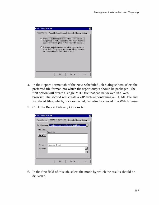
Management Information and Reporting
163
4. In the Report Format tab of the New Scheduled Job dialogue box, select the preferred file format into which the report output should be packaged. The first option will create a single MHT file that can be viewed in a Web browser. The second will create a ZIP archive containing an HTML file and its related files, which, once extracted, can also be viewed in a Web browser.
5. Click the Report Delivery Options tab.
6. In the first field of this tab, select the mode by which the results should be delivered.
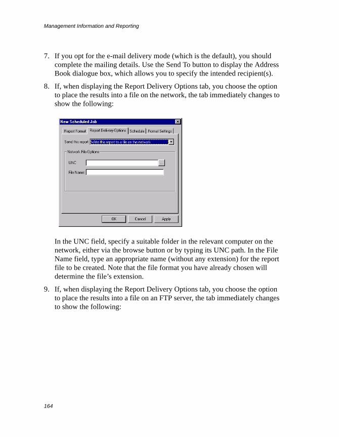
Management Information and Reporting
164
7. If you opt for the e-mail delivery mode (which is the default), you should complete the mailing details. Use the Send To button to display the Address Book dialogue box, which allows you to specify the intended recipient(s).
8. If, when displaying the Report Delivery Options tab, you choose the option to place the results into a file on the network, the tab immediately changes to show the following:
In the UNC field, specify a suitable folder in the relevant computer on the network, either via the browse button or by typing its UNC path. In the File Name field, type an appropriate name (without any extension) for the report file to be created. Note that the file format you have already chosen will determine the file’s extension.
9. If, when displaying the Report Delivery Options tab, you choose the option to place the results into a file on an FTP server, the tab immediately changes to show the following:
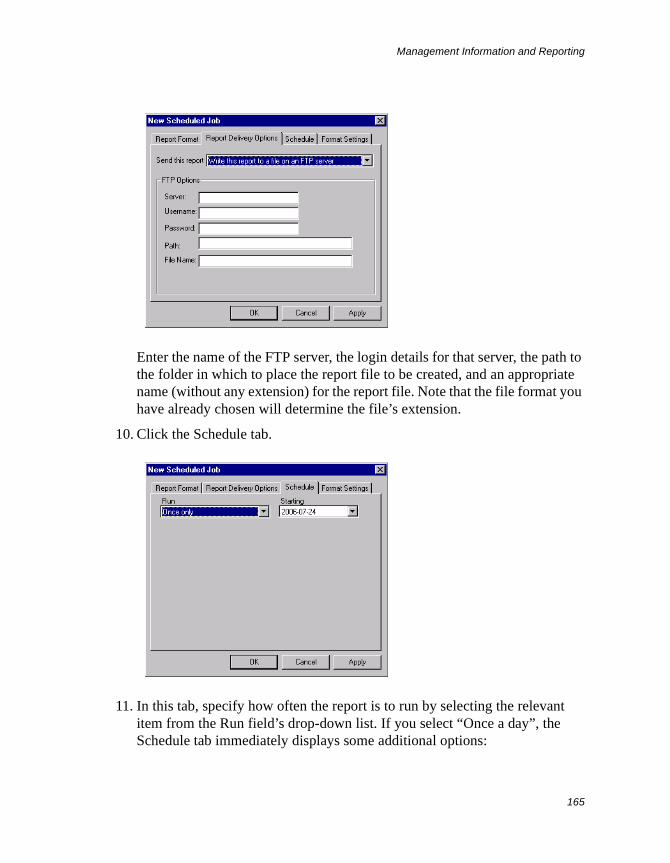
Management Information and Reporting
165
Enter the name of the FTP server, the login details for that server, the path to the folder in which to place the report file to be created, and an appropriate name (without any extension) for the report file. Note that the file format you have already chosen will determine the file’s extension.
10. Click the Schedule tab.
11. In this tab, specify how often the report is to run by selecting the relevant item from the Run field’s drop-down list. If you select “Once a day”, the Schedule tab immediately displays some additional options:
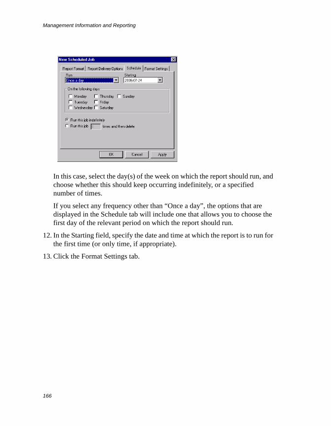
Management Information and Reporting
166
In this case, select the day(s) of the week on which the report should run, and choose whether this should keep occurring indefinitely, or a specified number of times.
If you select any frequency other than “Once a day”, the options that are displayed in the Schedule tab will include one that allows you to choose the first day of the relevant period on which the report should run.
12. In the Starting field, specify the date and time at which the report is to run for the first time (or only time, if appropriate).
13. Click the Format Settings tab.
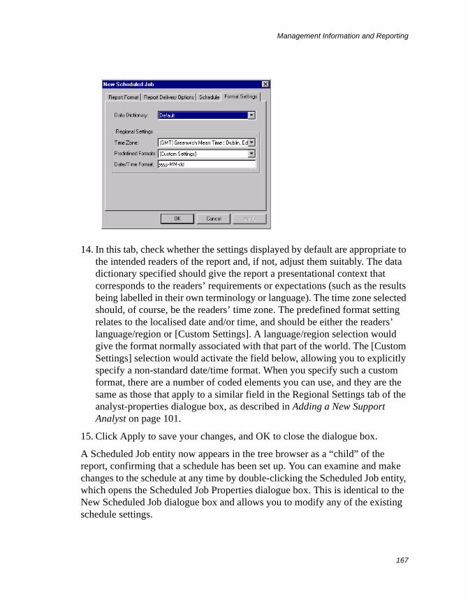
Management Information and Reporting
167
14. In this tab, check whether the settings displayed by default are appropriate to the intended readers of the report and, if not, adjust them suitably. The data dictionary specified should give the report a presentational context that corresponds to the readers’ requirements or expectations (such as the results being labelled in their own terminology or language). The time zone selected should, of course, be the readers’ time zone. The predefined format setting relates to the localised date and/or time, and should be either the readers’ language/region or [Custom Settings]. A language/region selection would give the format normally associated with that part of the world. The [Custom Settings] selection would activate the field below, allowing you to explicitly specify a non-standard date/time format. When you specify such a custom format, there are a number of coded elements you can use, and they are the same as those that apply to a similar field in the Regional Settings tab of the analyst-properties dialogue box, as described in Adding a New Support Analyst on page 101.
15. Click Apply to save your changes, and OK to close the dialogue box.
A Scheduled Job entity now appears in the tree browser as a “child” of the report, confirming that a schedule has been set up. You can examine and make changes to the schedule at any time by double-clicking the Scheduled Job entity, which opens the Scheduled Job Properties dialogue box. This is identical to the New Scheduled Job dialogue box and allows you to modify any of the existing schedule settings.
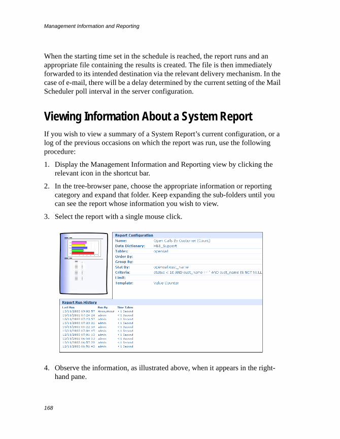
Management Information and Reporting
168
When the starting time set in the schedule is reached, the report runs and an appropriate file containing the results is created. The file is then immediately forwarded to its intended destination via the relevant delivery mechanism. In the case of e-mail, there will be a delay determined by the current setting of the Mail Scheduler poll interval in the server configuration.
Viewing Information About a System ReportIf you wish to view a summary of a System Report’s current configuration, or a log of the previous occasions on which the report was run, use the following procedure:
1. Display the Management Information and Reporting view by clicking the relevant icon in the shortcut bar.
2. In the tree-browser pane, choose the appropriate information or reporting category and expand that folder. Keep expanding the sub-folders until you can see the report whose information you wish to view.
3. Select the report with a single mouse click.
4. Observe the information, as illustrated above, when it appears in the right-hand pane.
Management Information and Reporting
169
The graphic in the top left-hand corner shows the overall format that reports based on this report’s template can have when the reports are fully configured.
The Report Configuration area displays a list of the report’s current configuration settings. It also indicates the data dictionary that was in use at the time the report was created. The relevance of the data dictionary here stems from the fact that certain customisable elements of the database schema (such as the display names of table columns) are used by reports, which means that data-dictionary dependence is possible for the display of some report characteristics.
The Report Run History area displays a log of the last ten occasions on which the report was run, showing the relevant dates and times, as well the ID of the analyst who ran it each time. The time taken for the report to run on each occasion is also shown.
Modifying System Report Chart CharacteristicsCharts embedded within System Reports can come in various shapes and sizes. If you wish to modify the visual characteristics of a particular chart in any given report to bring them into line with your own preferences, you can do so by first clicking the chart concerned. This replaces the report results with a Chart Constructor display consisting of a chart-preview image, a settings panel over the top, and another settings panel to the left.
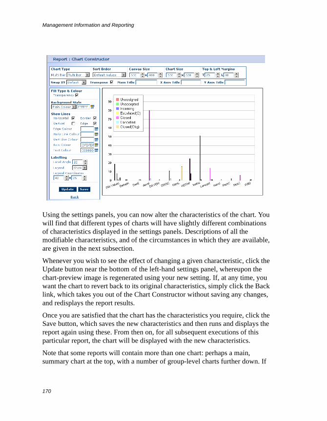
Management Information and Reporting
170
Using the settings panels, you can now alter the characteristics of the chart. You will find that different types of charts will have slightly different combinations of characteristics displayed in the settings panels. Descriptions of all the modifiable characteristics, and of the circumstances in which they are available, are given in the next subsection.
Whenever you wish to see the effect of changing a given characteristic, click the Update button near the bottom of the left-hand settings panel, whereupon the chart-preview image is regenerated using your new setting. If, at any time, you want the chart to revert back to its original characteristics, simply click the Back link, which takes you out of the Chart Constructor without saving any changes, and redisplays the report results.
Once you are satisfied that the chart has the characteristics you require, click the Save button, which saves the new characteristics and then runs and displays the report again using these. From then on, for all subsequent executions of this particular report, the chart will be displayed with the new characteristics.
Note that some reports will contain more than one chart: perhaps a main, summary chart at the top, with a number of group-level charts further down. If
Management Information and Reporting
171
you display the Chart Constructor for the main chart, any changes you make to its characteristics will affect only that chart. However, if you display the Chart Constructor for a group-level chart, your changes will affect all the other group-level charts as well, although not the main chart.
Chart Characteristics
The settings panels in the Chart Constructor allow you to alter many of the visual characteristics of a selected chart belonging to a report. Although most of the characteristics available for alteration are common to all types of chart, and will always be displayed in the panel, some will be visible only for certain chart types. In the descriptions of the characteristics given below, the circumstances under which the latter will be available are clearly stated.
Chart Type This defines the type of chart to be generated. Normally, you can select any of the following chart types:
• Pie chart
• 3D pie chart
• Bar chart
• 3D bar chart
• Line graph
• 3D line graph
• Area graph
• 3D area graph
For Grouped List reports, you can opt for the main chart to be multi-dimensional, in which case your possible chart-type choices would be as follows:
• Multi-dimensional arranged bar chart
• Multi-dimensional stacked bar chart
• Multi-dimensional area graph
• Multi-dimensional line graph
Sort Order This defines the kind of sorting that should apply to the items shown on the chart. For a bar chart, line graph or area graph, the items are ordered by
Management Information and Reporting
172
default from left to right (or from bottom to top), while for a pie chart, the default ordering is clockwise. The following kinds of sorting are available:
Default Values This option gives the chart items a fairly random distribution, as they are placed in the order in which the data is read from the database.
Reverse Values This option places the chart items in an order that is the reverse of the Default Values order.
Values Ascending This option does not apply to multi-dimensional charts. It places the chart items in ascending order, based on the count for each item.
Values Descending This option does not apply to multi-dimensional charts. It places the chart items in descending order, based on the count for each item.
Label Ascending This option places the chart items in ascending alphanumerical order, based on the label text.
Label Descending This option places the chart items in descending alphanumerical order, based on the label text.
Staggered Values This option does not apply to multi-dimensional charts. It places the chart items in an order of “alternating opposites”. The placing starts with the item that has the highest count, followed by the item with the lowest count. Then, the items with the next-highest and next-lowest counts are placed, and so on. This kind of distribution is most useful in pie charts where overlapping of item labels would otherwise occur due to adjacent segments being too thin.
Canvas Size These two settings define, in pixels, the horizontal and vertical dimensions of the “canvas” on which the chart is drawn.
Chart Size These apply to bar charts, line graphs and area graphs. They define, in pixels, the horizontal and vertical dimensions of the chart graphic itself.
Top & Left Margins These two settings apply to bar charts, line graphs and area graphs. They define, in pixels, the left and top margins of the chart, as measured between the edge of the canvas and the corresponding edge of the chart graphic (that is, the drawn chart itself, excluding any labels).
Centre Offset X & Y These two settings apply to pie charts. They define, in pixels, the position of the pie’s centre within the canvas, as measured from the centre point of the canvas.
Management Information and Reporting
173
Scaling This applies to pie charts. It defines the “flat” diameter of the pie, expressed as a percentage of the smaller dimension of the canvas.
Depth This is specific to 3D charts. It defines, in pixels, the depth of the chart graphic (that is, along the Z-axis). For a multi-depth pie chart, it would define the maximum depth (or “height”) of the pie.
Angle of View This is specific to 3D pie charts. It defines the apparent angle of view (in degrees) that the observer has of the pie, with 0 being the top view and 90 being the side view. Note that true perspective is not automatically maintained, as the pie’s depth is controlled independently of the angle.
Swap XY This applies to bar charts, line graphs and area graphs. Selection of Swap XY will switch over the X- and Y-axes of the chart. Selection of Default will switch these back to their default positions.
Main Title This defines a title for the chart. Any text typed in this field will appear, horizontally centralised, at the top of the canvas.
X Axis Title This applies to bar charts, line graphs and area graphs. It defines a title for the X-axis of the chart.
Y Axis Title This applies to bar charts, line graphs and area graphs. It defines a title for the Y-axis of the chart.
Multi Depth This option is specific to 3D pie charts. When enabled, it causes each segment of the pie to be displayed with a different depth, dropping by equal increments from maximum depth at the start angle in a clockwise direction. The respective depths therefore have no significance apart from a stylistic one.
Explode Pie This option is specific to pie charts. When enabled, it causes the specified segment (counting from the start angle) to be set apart from the remainder of the pie by the specified distance (in pixels).
Start Angle This is specific to pie charts. It defines, in degrees (relative to “12 o’clock”), the angle at which segment ordering begins, being the place in the pie where the starting edge of the first segment is located.
Fill Type & Colour These apply to all except multi-dimensional charts. The fill type defines mainly the colouring mode of the chart elements, of which there are three to choose from:
Management Information and Reporting
174
Default Palette With this option, each element is filled with a different colour from the palette provided.
One Colour This option allows you to select the single colour, of constant tone, with which all elements are to be filled. You select the actual colour by means of the adjacent Pick Colour button.
Gradient This option applies to bar charts and area graphs. It allows you to select the single colour, of gradually changing tone, with which all elements are to be filled. You select the actual colour by means of the adjacent Pick Colour button.
Another aspect of colour fill is Transparency. This option, when enabled, will make the chart’s grid lines and normally hidden parts of chart elements visible through all those elements that overlap them.
Background Style This defines the colouring style of the canvas background, of which there are three to choose from:
Plain Colour This option specifies the colouring style of the canvas background as being constant-tone and opaque. With an opaque canvas background, the colour of the canvas will stand out from that of the report as a whole. You select the actual colour by means of the adjacent Pick Colour button.
Gradient This option specifies the colouring style of the canvas background as an opaque one with repeating gradients. Again, an opaque canvas background allows the colour of the canvas to stand out from that of the report as a whole. You select the actual colour by means of the Gradient drop-down list.
Transparent This option specifies the colouring style of the canvas background as one that is transparent. When the background is transparent, it will be colourless, and the report’s background will be visible through it.
Show Lines The settings in this area govern which of the chart’s ruled lines should be displayed and, if any are, what colour they, and also the label text, should be. The enabling options are as follows:
Horizontal This option applies to bar charts, line graphs and area graphs. When enabled, it will cause horizontal grid lines to be displayed.
Vertical This option applies to bar charts, line graphs and area graphs. When enabled, it will cause vertical grid lines to be displayed.

Management Information and Reporting
175
Border This option, when enabled, will cause the canvas boundary to be made visible by the appearance of a border. Note that, if you copy a chart and paste it into another application, the border will be lost.
Edge This option, when enabled, will cause the lines defining the edges of the chart graphic to be displayed. For a pie chart, it will cause the lines defining the segment boundaries to be displayed.
Below the enabling options, there are the colour controls for these line elements, and for the text. To select a colour for a given element, use the relevant Pick Colour button. The elements are as follows:
Edge Colour This determines the colour of the lines defining the edges of the chart graphic, including the two axes (if not separately overriden). In the case of a pie chart, it determines the colour of the segment boundaries.
Horiz Line Colour This determines the colour of the horizontal grid lines on bar charts, line graphs and area graphs.
Vert Line Colour This determines the colour of the vertical grid lines on bar charts, line graphs and area graphs.
Axis Colour This determines the colour of the two axes on bar charts, line graphs and area graphs, when you want this to differ from the overall edge colour.
Text Colour This determines the colour of all label text.
Labelling The settings in this area are concerned with how the chart should be labelled. For pie charts, it is possible to display a colour-coded legend to augment the presentation. For other charts, you can specify the angle at which the X-axis labelling should be displayed. The settings available are as follows:
Legend This is specific to pie charts. By making the appropriate selection in the drop-down list, you can either show or hide the legend.
Legend Coordinates These are specific to pie charts. By entering appropriate X and Y values (which are in pixels, measured relative to the top left-hand corner of the canvas), you can position the legend anywhere on the canvas.
Label Angle This applies to bar charts, line graphs and area graphs. You specify the angle that the label text should make with the X-axis by entering an appropriate number (which is in degrees).
Management Information and Reporting
176
Discard Results This area applies to all except multi-dimensional charts. The first two fields here allow items with too high or too low a count (in comparison with the majority) to be excluded from the chart. This is useful when a few items having counts far below, or in excess of, the norm are seen to adversely affect chart readability, or when such items simply do not need to be compared with the others. If you wish to exclude high counts, type the required threshold value in the Above field. Similarly, to exclude low counts, you should type an appropriate value in the Below field.
The third field here allows you to specify the maximum number of records that are to be included in the statistics for the chart display.
System Report PromptingAn interactive System Report with configurable prompts, when run, will first prompt the user to input one or more items of information. Where multiple items are asked for, the relevant prompts are displayed one below the other. The information entered at any prompt is used by the report to limit (that is, to filter) the output appropriately. It is mandatory for the user to input data at such prompts.
In the configuration of any report, if you specify at least one filter operand as being a runtime value, you can then define the prompt(s) it should display. The data-input mechanism or format that a prompt will use defines the prompt type and can be any of the following:
• Date Range. This prompts for a start and end date.
• Time Range. This prompts for a start and end time on the day concerned.
• Date/Time Range. This prompts for a start and end date/time.
• Number Range. This prompts for a start and end number.
• Date/Time. This prompts for a specific date and time.
• Date. This prompts for a specific date.
• Time. This prompts for a specific time period in hours, minutes and seconds.
• Number. This prompts for a specific number.
• Text. This prompts for a text string.
Management Information and Reporting
177
• Database Pick List. This prompts for a database item selectable from a drop-down list. The list content would be built automatically from the values in the table column you specify for the prompt (subject to the constraints of an optional filter).
• User Defined Pick List. This prompts for an item selectable from a drop-down list. You would create the list content for the prompt yourself. Each selection item you create is made up of a display component mapped to an underlying value component, both of which would normally be the same. However, you can change the display component separately and, if you do, this would be the version that the user sees, while the underlying value would be the one that the report actually takes account of.
Creating and Configuring System ReportsYou use the Report wizard to build new System Reports and the Report Properties dialogue box to configure existing ones. When you create a new report, the wizard first asks you to choose a suitable template, and then guides you through the rest of the build process by means of an appropriate set of sequentially displayed dialogue boxes, each of which invites you to specify your requirements for a given aspect (or series of aspects) of the report concerned. When you reconfigure a report, you will find that the tabs in the Report Properties dialogue box reflect exactly the respective dialogue boxes that make up the wizard.
The precise aspects you have to define for a report will depend on the template on which the report is based. The following templates are currently available:
• Simple List
• Grouped List
• Boxed Grouped List
• Value Counter
• Grouped Value Counter
A template falls under one of two main categories: Lists or Value Counters. Lists mainly display textual lists of records (although these are sometimes augmented by graphical distributions), whereas Value Counters display numerical statistics, presented in graphical and/or textual form.
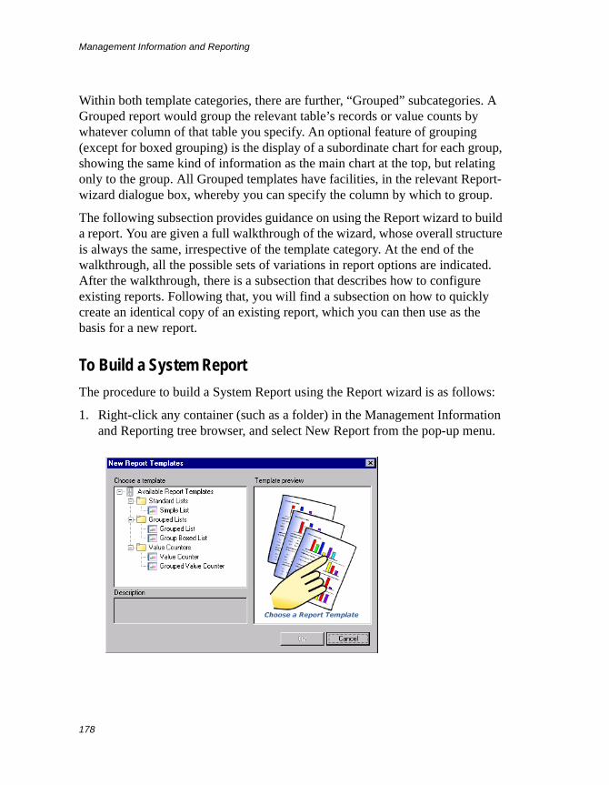
Management Information and Reporting
178
Within both template categories, there are further, “Grouped” subcategories. A Grouped report would group the relevant table’s records or value counts by whatever column of that table you specify. An optional feature of grouping (except for boxed grouping) is the display of a subordinate chart for each group, showing the same kind of information as the main chart at the top, but relating only to the group. All Grouped templates have facilities, in the relevant Report-wizard dialogue box, whereby you can specify the column by which to group.
The following subsection provides guidance on using the Report wizard to build a report. You are given a full walkthrough of the wizard, whose overall structure is always the same, irrespective of the template category. At the end of the walkthrough, all the possible sets of variations in report options are indicated. After the walkthrough, there is a subsection that describes how to configure existing reports. Following that, you will find a subsection on how to quickly create an identical copy of an existing report, which you can then use as the basis for a new report.
To Build a System Report
The procedure to build a System Report using the Report wizard is as follows:
1. Right-click any container (such as a folder) in the Management Information and Reporting tree browser, and select New Report from the pop-up menu.
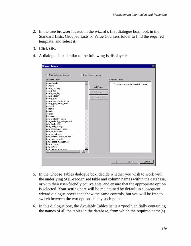
Management Information and Reporting
179
2. In the tree browser located in the wizard’s first dialogue box, look in the Standard Lists, Grouped Lists or Value Counters folder to find the required template, and select it.
3. Click OK.
4. A dialogue box similar to the following is displayed:
5. In the Choose Tables dialogue box, decide whether you wish to work with the underlying SQL-recognised table and column names within the database, or with their user-friendly equivalents, and ensure that the appropriate option is selected. Your setting here will be maintained by default in subsequent wizard dialogue boxes that show the same controls, but you will be free to switch between the two options at any such point.
6. In this dialogue box, the Available Tables list is a “pool”, initially containing the names of all the tables in the database, from which the required name(s)
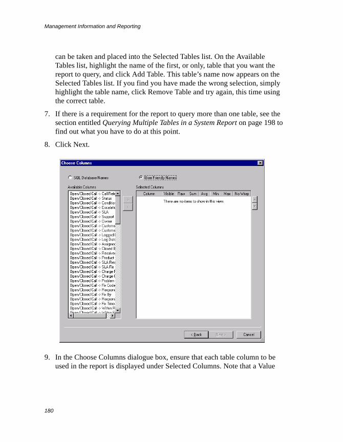
Management Information and Reporting
180
can be taken and placed into the Selected Tables list. On the Available Tables list, highlight the name of the first, or only, table that you want the report to query, and click Add Table. This table’s name now appears on the Selected Tables list. If you find you have made the wrong selection, simply highlight the table name, click Remove Table and try again, this time using the correct table.
7. If there is a requirement for the report to query more than one table, see the section entitled Querying Multiple Tables in a System Report on page 198 to find out what you have to do at this point.
8. Click Next.
9. In the Choose Columns dialogue box, ensure that each table column to be used in the report is displayed under Selected Columns. Note that a Value
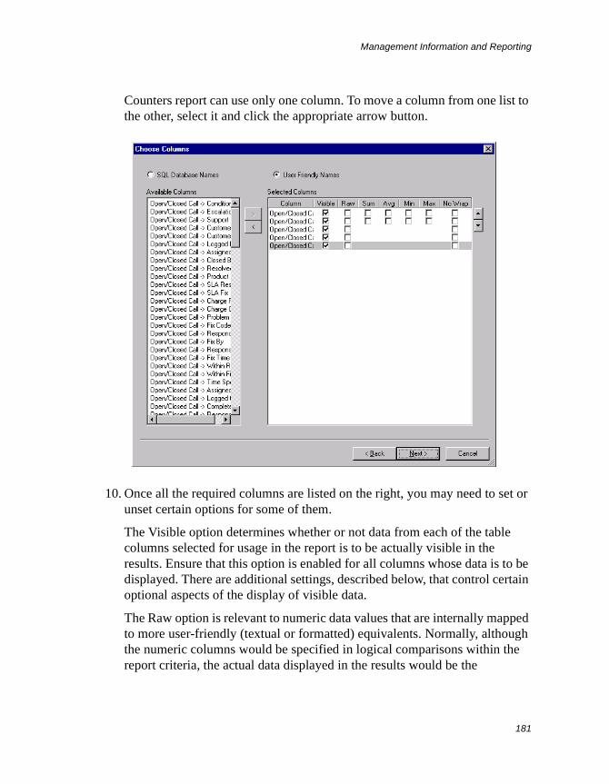
Management Information and Reporting
181
Counters report can use only one column. To move a column from one list to the other, select it and click the appropriate arrow button.
10. Once all the required columns are listed on the right, you may need to set or unset certain options for some of them.
The Visible option determines whether or not data from each of the table columns selected for usage in the report is to be actually visible in the results. Ensure that this option is enabled for all columns whose data is to be displayed. There are additional settings, described below, that control certain optional aspects of the display of visible data.
The Raw option is relevant to numeric data values that are internally mapped to more user-friendly (textual or formatted) equivalents. Normally, although the numeric columns would be specified in logical comparisons within the report criteria, the actual data displayed in the results would be the

Management Information and Reporting
182
corresponding user-friendly values. However, if you want the raw numeric values to be displayed for a given column (say, for diagnostic purposes), you should enable the relevant Raw option.
The next four options govern whether or not mechanisms are to be activated in the report to calculate value sums, value averages, minimum values and/or maximum values, respectively, for the data relating to each of the numeric columns. Ensure that the appropriate options are enabled for all numeric columns whose data is to be aggregated in these ways.
The No Wrap option determines whether or not the space taken up by the data and heading of each displayed column in the output report should be squashed and the text wrapped around when there are many columns to fit into the results page. If you wish to display a lot of columns, you should consider enabling this option for all of those whose contents will look messy when wrapped around.
If you wish to reposition any table-column entry on the list, select the entry and use the up and down buttons to the right of the list. Top and bottom on this list correspond to left and right, respectively, on the output report.
11. Click Next.
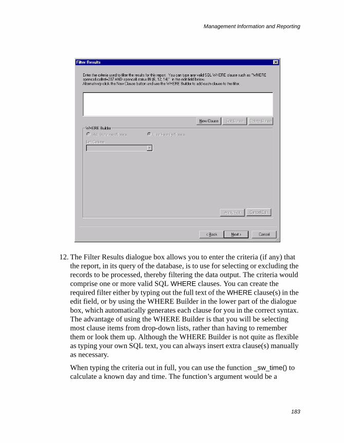
Management Information and Reporting
183
12. The Filter Results dialogue box allows you to enter the criteria (if any) that the report, in its query of the database, is to use for selecting or excluding the records to be processed, thereby filtering the data output. The criteria would comprise one or more valid SQL WHERE clauses. You can create the required filter either by typing out the full text of the WHERE clause(s) in the edit field, or by using the WHERE Builder in the lower part of the dialogue box, which automatically generates each clause for you in the correct syntax. The advantage of using the WHERE Builder is that you will be selecting most clause items from drop-down lists, rather than having to remember them or look them up. Although the WHERE Builder is not quite as flexible as typing your own SQL text, you can always insert extra clause(s) manually as necessary.
When typing the criteria out in full, you can use the function _sw_time() to calculate a known day and time. The function’s argument would be a
Management Information and Reporting
184
Supportworks standard context variable, as used in data-dictionary-based filters for customisation. For example, to refer to the start of today, you would specify the function as _sw_time(startoftoday). A full list of the context variables you can employ within the parentheses is given in an Appendix of the System Customisation Guide. Note that only the time-related variables are valid for report criteria.
For a prompted report, you would refer, in the SQL text, to the input data by means of a variable such as &[uv_arg1] or &[uv_arg2], where 1 represents the first (or only) prompt, 2 represents the second prompt, and so on. In the case of a range prompt, the variable representing the “From” data would be of the form &[uv_argf1], and the variable representing the “To” data would be of the form &[uv_argt1].
For details of how to use the WHERE Builder, see the section entitled Using the WHERE Builder in a System Report on page 192.
13. Click Next.
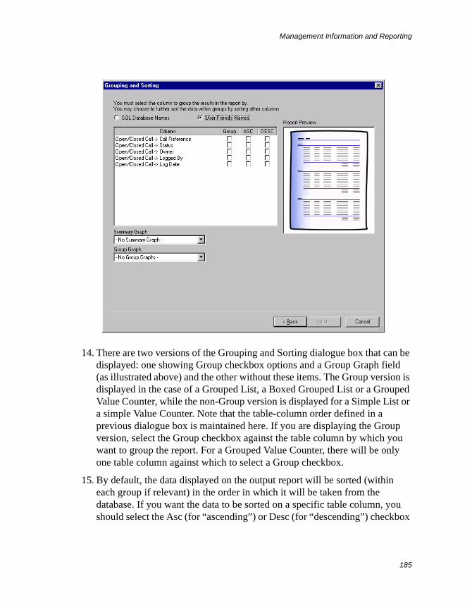
Management Information and Reporting
185
14. There are two versions of the Grouping and Sorting dialogue box that can be displayed: one showing Group checkbox options and a Group Graph field (as illustrated above) and the other without these items. The Group version is displayed in the case of a Grouped List, a Boxed Grouped List or a Grouped Value Counter, while the non-Group version is displayed for a Simple List or a simple Value Counter. Note that the table-column order defined in a previous dialogue box is maintained here. If you are displaying the Group version, select the Group checkbox against the table column by which you want to group the report. For a Grouped Value Counter, there will be only one table column against which to select a Group checkbox.
15. By default, the data displayed on the output report will be sorted (within each group if relevant) in the order in which it will be taken from the database. If you want the data to be sorted on a specific table column, you should select the Asc (for “ascending”) or Desc (for “descending”) checkbox
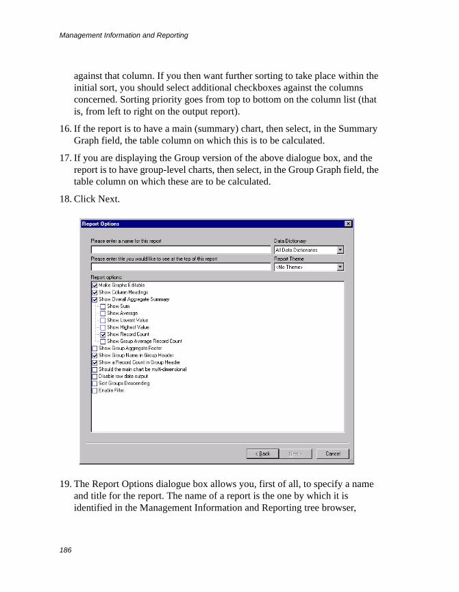
Management Information and Reporting
186
against that column. If you then want further sorting to take place within the initial sort, you should select additional checkboxes against the columns concerned. Sorting priority goes from top to bottom on the column list (that is, from left to right on the output report).
16. If the report is to have a main (summary) chart, then select, in the Summary Graph field, the table column on which this is to be calculated.
17. If you are displaying the Group version of the above dialogue box, and the report is to have group-level charts, then select, in the Group Graph field, the table column on which these are to be calculated.
18. Click Next.
19. The Report Options dialogue box allows you, first of all, to specify a name and title for the report. The name of a report is the one by which it is identified in the Management Information and Reporting tree browser,
Management Information and Reporting
187
whereas the title is what appears at the top of the report’s output display. If you leave the title field blank, the title will default to the report’s name. Enter an appropriate and accurate name and title for the report in the relevant fields. Note that you can use prompt variables such as &[uv_arg1] in the title field if you wish.
Secondly, this dialogue box allows you to allocate a specific data dictionary, or all data dictionaries, to the report. A specific data dictionary allocation ensures that the report will be visible only to those analysts that have this data dictionary loaded. (For such filtration to work, you must have the relevant criteria set up, for the data dictionary concerned, in a Global Parameters folder called “Reports”, as described in the System Customisation Guide.) In the Data Dictionary field, select the required data dictionary or leave the setting as All Data Dictionaries.
Thirdly, this dialogue box allows you to specify a theme for the output report. A theme is a preset look-and-feel that you can give to a report, affecting its displayed fonts, colours, borders and background. In the Report Theme field, select the theme you require or leave it at the default setting of <No Theme>.
Lastly, this dialogue box allows you to enable and disable various report options. The options available will differ with the report template. The different sets of possible options are described in the following subsections.
20. Click Finish. The wizard saves the configuration and then terminates. The new report will now appear at the bottom of the System Reports section of the Management Information and Reporting tree browser. You can move the report to any folder within that section by dragging it with the mouse.
The Options Available for a Simple List Report
The following options are available, in the final dialogue box of the Report wizard, for a System Report based on the Simple List template:
Make Graphs Editable This option, when enabled, allows the user to successfully save, from within the Chart Constructor, any changes made to the charts in the report.
Show Column Headings On report outputs, records are listed in tabular form, with the columns distributed horizontally across the display. If you want the
Management Information and Reporting
188
column headings to be visible, ensure that this option is enabled. The column headings will be equivalent to the display names defined for the columns in the data dictionary.
Show Overall Aggregate Summary If this option is enabled, an Overall Totals section, capable of showing overall aggregate values, will appear at the end of the report output. The aggregates would consist of value sums, value averages, minimum values and/or maximum values, shown under those numeric columns for which these aggregate figures are to be calculated (as configured in step 10 above). Another possible aggregate would be the number of records displayed. Each aggregate value is separately selected for display by enabling the appropriate child option below.
Show Sum This child option, when enabled, will cause the sum total of the values in a given column to be displayed.
Show Average This child option, when enabled, will cause the average of the values in a given column to be shown.
Show Lowest Value This child option, when enabled, will cause the minimum value in a given column to be shown.
Show Highest Value This child option, when enabled, will cause the maximum value in a given column to be shown.
Show Record Count This is the child option that allows you to enable or disable specifically the part of the Overall Totals section that shows the total number of records displayed.
Disable Row Data Output If this option is enabled, the textual part(s) of the report will be output without any data rows. Such an effect may be useful for testing purposes.
Enable Filter If you want the report output to display column-related filter fields, you should enable this option.
The Options Available for a Grouped List Report
The following options are available, in the final dialogue box of the Report wizard, for a System Report based on the Grouped List template:
Management Information and Reporting
189
Make Graphs Editable This option, when enabled, allows the user to successfully save, from within the Chart Constructor, any changes made to the charts in the report.
Show Column Headings On report outputs, records are listed in tabular form, with the columns distributed horizontally across the display. If you want the column headings to be visible, ensure that this option is enabled. The column headings will be equivalent to the display names defined for the columns in the data dictionary.
Show Overall Aggregate Summary If this option is enabled, an Overall Totals section, capable of showing overall aggregate values, will appear at the end of the report output. The aggregates would consist of value sums, value averages, minimum values and/or maximum values, shown under those numeric columns for which these aggregate figures are to be calculated (as configured in step 10 above). Other possible aggregates would be the number of records displayed, and the average number of records per group. Each aggregate value is separately selected for display by enabling the appropriate child option below.
Show Sum This child option, when enabled, will cause the sum total of the values in a given column to be displayed.
Show Average This child option, when enabled, will cause the average of the values in a given column to be shown.
Show Lowest Value This child option, when enabled, will cause the minimum value in a given column to be shown.
Show Highest Value This child option, when enabled, will cause the maximum value in a given column to be shown.
Show Record Count This child option, when enabled, will cause the number of records displayed to be shown. A similar record-count will appear at the end of each group if Show Group Aggregate Folder (see below) is also enabled.
Show Group Average Record Count This child option, when enabled, will cause the average number of records per group to be shown (in parentheses after the overall total record count), provided that Show Record Count is also enabled.
Management Information and Reporting
190
Show Group Aggregate Footer If this option is enabled, a footer section showing group-related aggregate values will appear at the end of each group in the report output. In just the same way as for the Overall Totals section, the aggregates would consist of value sums, value averages, minimum values and/or maximum values, shown under those numeric columns for which these aggregate figures are to be calculated (as configured in step 10 above). Another possible aggregate would be the number of records displayed in the group. This record count would appear only if Show Record Count is enabled as well.
Show Group Name in Group Header This option, when enabled, will cause the names of groups to be displayed in their respective headers.
Show a Record Count in Group Header This option, when enabled, will cause the number of records in each group to be displayed in the groups’ respective headers.
Should the main chart be multi-dimensional This option, when enabled, will cause group elements in the main chart to be subdivided into their respective components.
Disable Row Data Output If this option is enabled, the textual part(s) of the report will be output without any data rows. Such an effect may be useful for testing purposes.
Sort Groups Descending Normally, the report’s groups are displayed in ascending order, which means that the group name with the lowest underlying alphanumerical value would be at the top, and the name with the highest would be at the bottom. However, if you wish to reverse the order, you should enable this option.
Enable Filter If you want the report output to display column-related filter fields, you should enable this option.
The Options Available for a Boxed Grouped List Report
The only option available, in the final dialogue box of the Report wizard, for a System Report based on the Boxed Grouped List template is the following:
Show Group Name in Group Header This option, when enabled, will cause the names of groups to be displayed in their respective headers.
Note that Boxed Grouped List reports do not support charts or aggregates.
Management Information and Reporting
191
The Options Available for a Value Counter Report
The only option available, in the final dialogue box of the Report wizard, for a System Report based on the Value Counter template is the following:
Make Graphs Editable This option, when enabled, allows the user to successfully save, from within the Chart Constructor, any changes made to the charts in the report.
The Options Available for a Grouped Value Counter Report
The following options are available, in the final dialogue box of the Report wizard, for a System Report based on the Grouped Value Counter template:
Make Graphs Editable This option, when enabled, allows the user to successfully save, from within the Chart Constructor, any changes made to the charts in the report.
Show Overall Aggregate Summary If this option is enabled, an Overall Totals section, capable of showing overall aggregate values, will appear at the end of the report output. The aggregates would consist of value sums, value averages, minimum values and/or maximum values, shown under those numeric columns for which these aggregate figures are to be calculated (as configured in step 10 above). Other possible aggregates would be the number of records displayed, and the average number of records per group. Each aggregate value is separately selected for display by enabling the appropriate child option below.
Show Sum This child option, when enabled, will cause the sum total of the values in a given column to be displayed.
Show Average This child option, when enabled, will cause the average of the values in a given column to be shown.
Show Lowest Value This child option, when enabled, will cause the minimum value in a given column to be shown.
Show Highest Value This child option, when enabled, will cause the maximum value in a given column to be shown.
Show Record Count This child option, when enabled, will cause the number of records displayed to be shown. A similar record-count will appear at the
Management Information and Reporting
192
end of each group if Show Group Aggregate Folder (see below) is also enabled.
Show Group Average Record Count This child option, when enabled, will cause the average number of records per group to be shown (in parentheses after the overall total record count), provided that Show Record Count is also enabled.
Show Group Aggregate Footer If this option is enabled, a footer section showing group-related aggregate values will appear at the end of each group in the report output. In just the same way as for the Overall Totals section, the aggregates would consist of value sums, value averages, minimum values and/or maximum values, shown under those numeric columns for which these aggregate figures are to be calculated (as configured in step 10 above). Another possible aggregate would be the number of records displayed in the group. This record count would appear only if Show Record Count is enabled as well.
Using the WHERE Builder in a System Report
When you are building or configuring a System Report, you can opt to use the WHERE Builder to define the criteria by which the report should filter the queried data. By working your way through a quick and easy selection-based procedure to generate each clause, you will be able to build any required SQL WHERE expression with only minimal knowledge of SQL. The resulting expression, as it grows with the addition of each clause, will be visible in the edit field of the Filter Results dialogue. You will be able to modify the logical operators directly if necessary.
The procedure to generate a WHERE clause is as follows:
1. In the Filter Results dialogue, click the New Clause button. The WHERE Builder section of the dialogue is activated, showing the initial field to be populated.
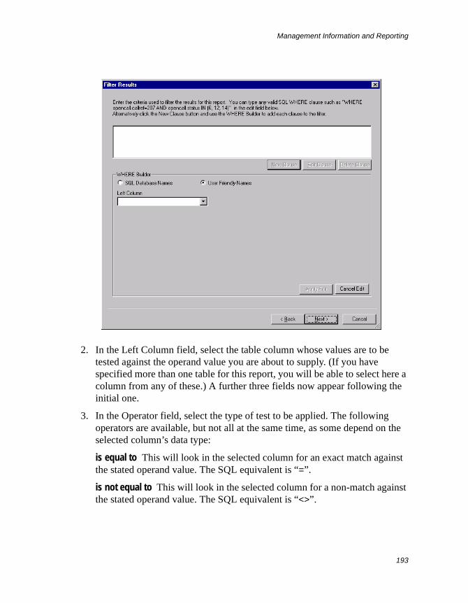
Management Information and Reporting
193
2. In the Left Column field, select the table column whose values are to be tested against the operand value you are about to supply. (If you have specified more than one table for this report, you will be able to select here a column from any of these.) A further three fields now appear following the initial one.
3. In the Operator field, select the type of test to be applied. The following operators are available, but not all at the same time, as some depend on the selected column’s data type:
is equal to This will look in the selected column for an exact match against the stated operand value. The SQL equivalent is “=”.
is not equal to This will look in the selected column for a non-match against the stated operand value. The SQL equivalent is “<>”.
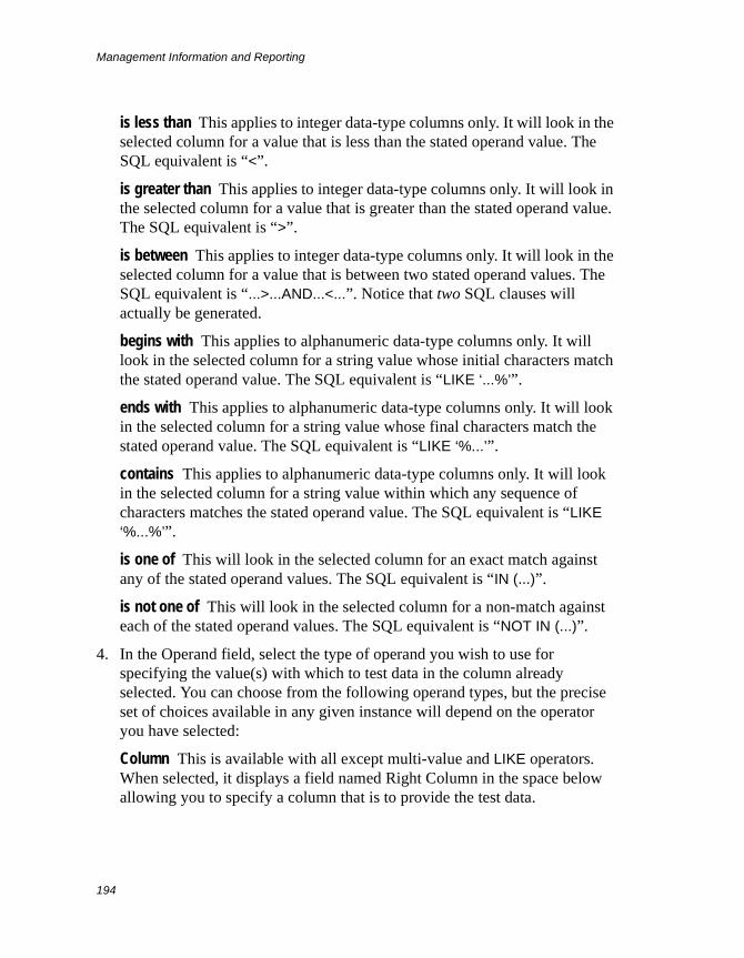
Management Information and Reporting
194
is less than This applies to integer data-type columns only. It will look in the selected column for a value that is less than the stated operand value. The SQL equivalent is “<”.
is greater than This applies to integer data-type columns only. It will look in the selected column for a value that is greater than the stated operand value. The SQL equivalent is “>”.
is between This applies to integer data-type columns only. It will look in the selected column for a value that is between two stated operand values. The SQL equivalent is “...>...AND...<...”. Notice that two SQL clauses will actually be generated.
begins with This applies to alphanumeric data-type columns only. It will look in the selected column for a string value whose initial characters match the stated operand value. The SQL equivalent is “LIKE ‘...%’”.
ends with This applies to alphanumeric data-type columns only. It will look in the selected column for a string value whose final characters match the stated operand value. The SQL equivalent is “LIKE ‘%...’”.
contains This applies to alphanumeric data-type columns only. It will look in the selected column for a string value within which any sequence of characters matches the stated operand value. The SQL equivalent is “LIKE ‘%...%’”.
is one of This will look in the selected column for an exact match against any of the stated operand values. The SQL equivalent is “IN (...)”.
is not one of This will look in the selected column for a non-match against each of the stated operand values. The SQL equivalent is “NOT IN (...)”.
4. In the Operand field, select the type of operand you wish to use for specifying the value(s) with which to test data in the column already selected. You can choose from the following operand types, but the precise set of choices available in any given instance will depend on the operator you have selected:
Column This is available with all except multi-value and LIKE operators. When selected, it displays a field named Right Column in the space below allowing you to specify a column that is to provide the test data.
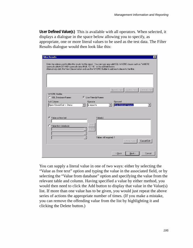
Management Information and Reporting
195
User Defined Value(s) This is available with all operators. When selected, it displays a dialogue in the space below allowing you to specify, as appropriate, one or more literal values to be used as the test data. The Filter Results dialogue would then look like this:
You can supply a literal value in one of two ways: either by selecting the “Value as free text” option and typing the value in the associated field, or by selecting the “Value from database” option and specifying the value from the relevant table and column. Having specified a value by either method, you would then need to click the Add button to display that value in the Value(s) list. If more than one value has to be given, you would just repeat the above series of actions the appropriate number of times. (If you make a mistake, you can remove the offending value from the list by highlighting it and clicking the Delete button.)
Management Information and Reporting
196
Runtime Defined Value This is available with all except IN/NOT IN operators, and allows you to set up user prompts by which the person running the report will be able to filter the query results. If you want the users of the report to be prompted in this way, see the subsection entitled Setting Up User Prompts for a System Report on page 196 for instructions on what to do at this point.
5. Once the required operand value, or set of operand values, is in place, click Apply Edit. Your configuration data is committed to the report, and the generated clause is added to the edit field at the top. If there was at least one clause displayed there already, the new clause would be prefixed with an AND by default (which you can manually change to an OR if required).
If you wish to generate any further clauses, you will need to repeat the above procedure for each of them.
Setting Up User Prompts for a System Report
When using the WHERE Builder to generate SQL clauses for a System Report filter, you can make provision for testing not only against predefined values but also against values entered by the report user at runtime.
To set up a prompt that allows users to enter filter values when running reports, follow the instructions given here:
1. In the WHERE Builder section of the Filter Results dialogue, ensure that you have chosen the table column whose data is to be tested against the data supplied by the report user, and that you have selected a suitable operator (as described in the procedure for using the WHERE Builder above).
2. In the Operand field, select Runtime Prompted Value.
3. Click the Add Prompt button that has now appeared in the space below. You are presented with the Prompt Properties dialogue box in which you can now proceed to configure the prompt.
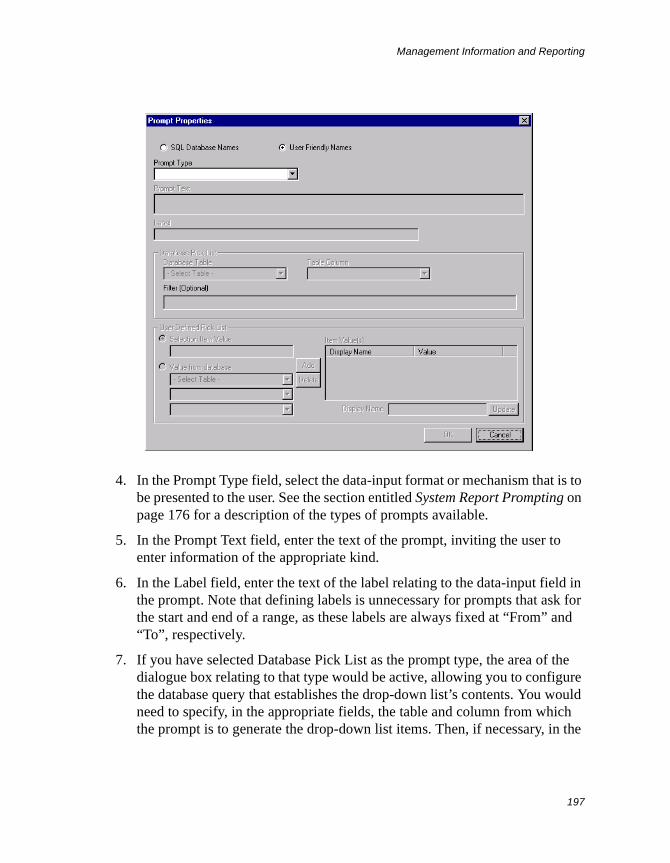
Management Information and Reporting
197
4. In the Prompt Type field, select the data-input format or mechanism that is to be presented to the user. See the section entitled System Report Prompting on page 176 for a description of the types of prompts available.
5. In the Prompt Text field, enter the text of the prompt, inviting the user to enter information of the appropriate kind.
6. In the Label field, enter the text of the label relating to the data-input field in the prompt. Note that defining labels is unnecessary for prompts that ask for the start and end of a range, as these labels are always fixed at “From” and “To”, respectively.
7. If you have selected Database Pick List as the prompt type, the area of the dialogue box relating to that type would be active, allowing you to configure the database query that establishes the drop-down list’s contents. You would need to specify, in the appropriate fields, the table and column from which the prompt is to generate the drop-down list items. Then, if necessary, in the
Management Information and Reporting
198
Filter field, you could enter an SQL expression for the purpose of limiting what will appear in the prompt field’s drop-down list.
8. If you have selected User Defined Pick List as the prompt type, the area of the dialogue box relating to that type would be active, allowing you to specify the drop-down list’s contents literally.
You can supply an item for the list in one of two ways: either by selecting the “Selection item value” option and typing the required string of characters in the associated field, or by selecting the “Value from database” option and specifying the required string from the relevant table and column. Having specified an item by either method, you would then need to click the Add button to display that item in the Item Value(s) list. As you would normally need to supply more than one item for a list, you would just repeat the above series of actions the appropriate number of times. (If you make a mistake, you can remove the offending item from the list by highlighting it and clicking the Delete button.)
For any clause where the values to be tested are non-user-friendly and therefore not suitable for use as selectable items in the prompt field’s drop-down list, you can specify display names against those underlying values. The report user would then see the display names in the drop-down list, instead of the underlying string values you have supplied for it. To specify a display name for a list item, first ensure that you have added it to the Item Value(s) list. Then highlight it and, in the Display Name field, type a suitable name. Click the Update button and observe that you now have the entered name mapped against the underlying value.
9. Click OK. The Prompt Properties dialogue box closes.
10. Back in the Filter Results dialogue, click Apply Edit as usual to commit your configuration data and to generate the corresponding WHERE clause.
If you wish to create any further prompts, you will need to repeat the above procedure, configuring each prompt in a separate WHERE clause.
Querying Multiple Tables in a System Report
Sometimes, you may require a System Report to display data from more than one table. These tables would invariably be related to each other in some way.
Management Information and Reporting
199
For example, the Open/Closed Call table contains a customer-identity column whose data values would reflect those held in a corresponding column in the Customer table. Thus, with such a relationship existing between these two tables, you may want a report designed to return a list of calls to also include various details of the customer associated with each call.
This kind of querying can be achieved by means of multi-table selection in the report’s SQL statement, which is possible only if appropriate JOIN...ON conditions are included. One JOIN...ON condition would be needed for each additional table that has to be queried. A JOIN...ON condition would be in the form of an expression that filters the data from the two tables concerned in such a way as to obtain the required combination of record-pairs in the returned results. The most useful kind of expression would be a single equality clause specifying a match between related columns in the two separate tables. This would look at each record in the left-hand table in turn and temporarily combine it with a record, from the right-hand table, that relates to it by virtue of matching values in the two related columns. If, for a given record, no related record is found, it is omitted from the results.
A variant of the JOIN...ON condition is LEFT JOIN...ON, which, instead of filtering out every record for which no related record is found, will actually include such records in the results, but with the columns added from the right-hand table indicating null values. The mechanism employed by another variant, the RIGHT JOIN...ON condition, works in reverse, in that it looks at individual records in the right-hand table and tries to find related records in the left-hand table with which to temporarily combine them. In this case, it would be the columns added from the left-hand table that would show null values when no related record can be found.
When you are building or configuring a report, you can implement JOINs by typing the necessary SQL directly into an edit field and/or by using the JOIN Builder, which is similar in operation to the WHERE Builder.
Note JOINs are currently not supported for Value Counter report templates, while for Grouped Value Counter report templates there is a limit of two tables.
To include JOINs in a report, follow the instructions given here:
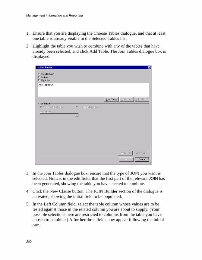
Management Information and Reporting
200
1. Ensure that you are displaying the Choose Tables dialogue, and that at least one table is already visible in the Selected Tables list.
2. Highlight the table you wish to combine with any of the tables that have already been selected, and click Add Table. The Join Tables dialogue box is displayed.
3. In the Join Tables dialogue box, ensure that the type of JOIN you want is selected. Notice, in the edit field, that the first part of the relevant JOIN has been generated, showing the table you have elected to combine.
4. Click the New Clause button. The JOIN Builder section of the dialogue is activated, showing the initial field to be populated.
5. In the Left Column field, select the table column whose values are to be tested against those in the related column you are about to supply. (Your possible selections here are restricted to columns from the table you have chosen to combine.) A further three fields now appear following the initial one.
Management Information and Reporting
201
6. In the Operator field, select the type of test to be applied. Although the same operators are available here as for the WHERE Builder, it would normally only make sense to use “is equal to”.
7. In the Operand field, select the type of operand you wish to use for specifying the value(s) with which to test data in the column already selected. You can choose from the same operand types as are available in the WHERE Builder, but normally only “Column” would make any sense here. When Column is selected, it displays a field named Right Column in the space below allowing you to specify a column that is to provide the test data. This should be a related column belonging to any of the tables that have already been selected.
8. Click Apply Edit. Your configuration data is committed to the report, and the generated clause is added to the edit field at the top. If there was at least one clause displayed there already, the new clause would be prefixed with an AND by default (which you can manually change to an OR if required).
9. If you wish to generate any further clauses, you will need to repeat the above procedure from step 4 onwards for each of them.
10. Click OK. Notice that the table you elected to combine is now listed under Selected Tables in the Choose Tables dialogue.
If you now wish to combine an additional table with any of the selected ones, you will need to repeat the entire procedure given above.
To Configure an Existing System Report
If you wish to reconfigure an existing System Report, right-click the report concerned in the Management Information and Reporting tree browser, and select Properties from the menu that pops up. The Report Properties dialogue box is displayed.
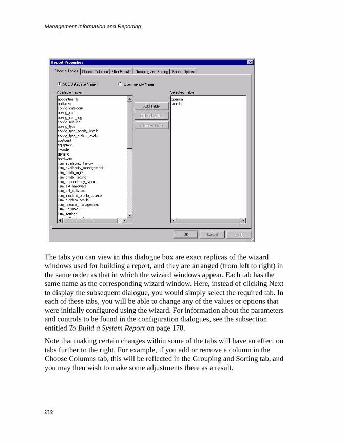
Management Information and Reporting
202
The tabs you can view in this dialogue box are exact replicas of the wizard windows used for building a report, and they are arranged (from left to right) in the same order as that in which the wizard windows appear. Each tab has the same name as the corresponding wizard window. Here, instead of clicking Next to display the subsequent dialogue, you would simply select the required tab. In each of these tabs, you will be able to change any of the values or options that were initially configured using the wizard. For information about the parameters and controls to be found in the configuration dialogues, see the subsection entitled To Build a System Report on page 178.
Note that making certain changes within some of the tabs will have an effect on tabs further to the right. For example, if you add or remove a column in the Choose Columns tab, this will be reflected in the Grouping and Sorting tab, and you may then wish to make some adjustments there as a result.
Management Information and Reporting
203
Editing Clauses in a System Report’s Filter
The Filter Results tab of the Report Properties dialogue box contains the current configuration of the report’s SQL filter. As usual, you can edit the filter one clause at a time using the WHERE Builder and also directly (outside of any generated clauses) in the edit field.
In the edit field, each generated clause in the filter expression is shown underlined. You select such a clause for editing or deletion by clicking anywhere within it.
To edit a generated clause, select it and click Edit Clause. The WHERE Builder becomes active, displaying all the relevant fields and their previously configured values. You can now make any changes you want. When you have finished, click Apply Edit to commit your changes to the report. Note that, while you are editing a clause, you can click Cancel Edit to make it revert to its previous values.
To delete a generated clause from the expression, select it and click Delete Clause. Notice that the clause has now disappeared from the edit field. You will need to remove any associated logical operator manually.
To Create a Copy of an Existing System Report
The quickest way of building a new System Report is to create a copy of an existing report that is similar to the one you require, and then make the necessary adjustments to the configuration of that copy.
To create a copy of a report, right-click it in the Management Information and Reporting tree browser and select Create Copy of Report from the menu that pops up. You are immediately prompted for the name of the new report. Enter a suitable name and click OK. The new report appears in the same expanded folder (or root container) as the one from which you copied the report.
You can now right-click the new report and select Properties from the pop-up menu to display the report’s configuration. See the previous section To Configure an Existing System Report on page 201 for details of how to adjust the configuration of a report.
Management Information and Reporting
204
Sharing System Reports with Other SystemsIf you have more than one Supportworks system and you wish to take copies of System Reports from one system and install these on another, you can use the application’s export and import facilities. The export function saves reports as an XML-formatted file, and the import function takes the content of any previously exported XML report file and installs it on the system as new reports.
To Export One or More System Reports
You can export System Reports either individually or in container-based groups. Irrespective of the number of reports exported in a given operation, just a single XML file is created.
To export an individual report, right-click it in the Management Information and Reporting tree browser and select Export Report from the menu that pops up. The Save As dialogue box is displayed. In this dialogue box, select a suitable folder in which to save the XML file, suitably edit the name of the file, and click Save. The file is created and placed in the chosen location.
To export all the reports in a particular folder, you would have to start off the process by right-clicking the folder concerned (at any level) and selecting Export Reports from the pop-up menu. To export all available reports on the system, you would start by right-clicking the System Reports container. In both of these cases, once the XML file has been created, you are presented with a summary of the numbers of folders and reports successfully exported. Just click OK to finish the process.
To Import One or More System Reports
You would import System Reports from XML report files that have previously been created by an export action.
To import a report, right-click the root container, or any existing folder in which the new report is to reside, and select Import Reports from the menu that pops up. The Open dialogue box is displayed. In this dialogue box, select the XML report file whose contents you wish to import, and click Open. The constituent reports are installed in the chosen container. If there was only one report in the XML file, you should be able to view that item immediately in the Management
Management Information and Reporting
205
Information and Reporting tree browser. However, with multiple reports and their folders, you would first have to exit from the view and then come back into it before they become visible.
Managing System ReportsThe Management Information and Reporting tree browser makes available various basic management functions that you can carry out on System Reports and their containers, including folder creation, folder and report deletion, folder renaming, and report moving. These are described in the following subsections.
Creating a New System Report Folder
To create a new System Report folder, right-click the root container, or any existing folder in which the new folder is to reside, and select New Folder from the menu that pops up. You are presented with a prompt to enter a name for the new folder. Type in a suitable name and click OK. The new folder appears in the chosen container.
Deleting a System Report Folder
To delete a System Report folder, right-click it and select Delete Folder from the pop-up menu. If the folder contains any further folders or any reports, a confirmation prompt would be displayed. At this prompt, click Yes, whereupon the folder is deleted.
Renaming a System Report Folder
To rename a System Report folder, right-click it and select Rename Folder from the pop-up menu. You are presented with a prompt to enter a new name for the folder. Suitably edit the name and click OK. The folder now has the new name.
Moving a System Report to Another Report Folder
To move a System Report to another folder, select the report item in the tree browser and drag it over to the relevant folder.

Management Information and Reporting
206
Deleting a System Report
To delete a System Report, right-click the item in the tree browser and select Delete Report from the pop-up menu. At the confirmation prompt, click Yes, whereupon the report is deleted.
Dashboard: Real-Time Data Display
207
Dashboard: Real-Time Data Display
Note Dashboard is not available in Supportworks Essentials.
Supportworks Dashboard is a stand-alone client application (running independently of the main client) whose function is to display real-time graphical statistics based on call-related data obtained from the results of predefined SQL queries that are automatically submitted to the Supportworks database. For each Dashboard instance, you can display up to six different statistical charts simultaneously, and you can specify the frequency at which the queries are submitted (and hence the rate at which the charts are refreshed). Your choice of charts to display would be from a “pool” of preconfigured charts to which you can add more at any time.
You can run Dashboard from any computer where the main Supportworks client is installed. Note that Dashboard uses a concurrent licence just like the client.
Starting UpTo run Dashboard, select Start > Programs > Supportworks Client > Supportworks Dashboard. The Dashboard window opens, displaying the currently stored configuration of charts. The first time you run Dashboard, you would have no configuration of your own, which means that it would be the default configuration supplied with Supportworks (in the file named swdashconf.xml) that is loaded and displayed, after having been automatically copied over from the server and saved locally under a different name (swdbconf.xml). All configuration changes you may make from now on within the Dashboard client (both overall and chart-specific) will be saved in this local file.
The default configuration defines a number of example charts, of which six are displayed as follows:
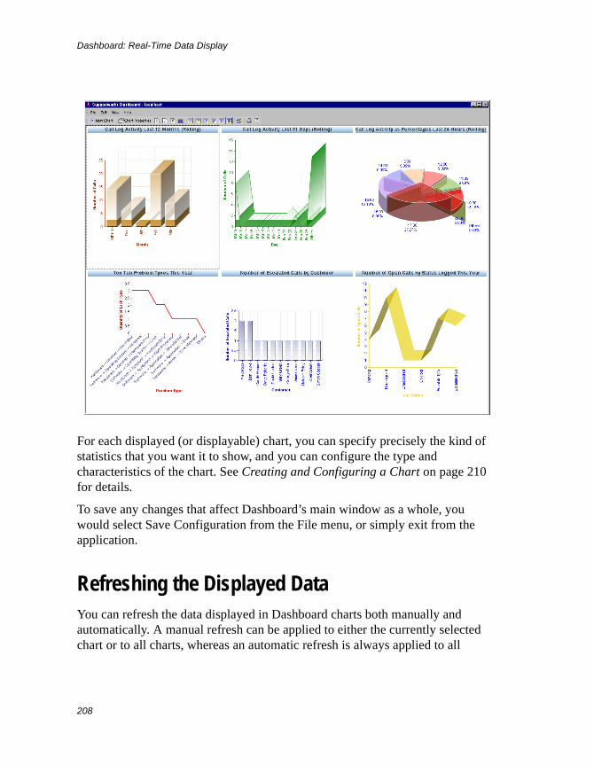
Dashboard: Real-Time Data Display
208
For each displayed (or displayable) chart, you can specify precisely the kind of statistics that you want it to show, and you can configure the type and characteristics of the chart. See Creating and Configuring a Chart on page 210 for details.
To save any changes that affect Dashboard’s main window as a whole, you would select Save Configuration from the File menu, or simply exit from the application.
Refreshing the Displayed DataYou can refresh the data displayed in Dashboard charts both manually and automatically. A manual refresh can be applied to either the currently selected chart or to all charts, whereas an automatic refresh is always applied to all
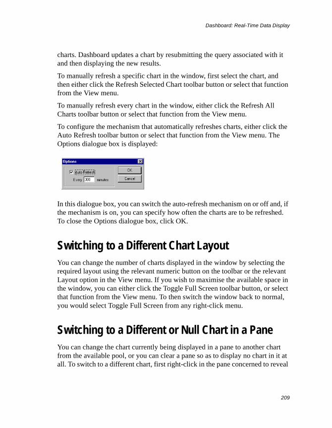
Dashboard: Real-Time Data Display
209
charts. Dashboard updates a chart by resubmitting the query associated with it and then displaying the new results.
To manually refresh a specific chart in the window, first select the chart, and then either click the Refresh Selected Chart toolbar button or select that function from the View menu.
To manually refresh every chart in the window, either click the Refresh All Charts toolbar button or select that function from the View menu.
To configure the mechanism that automatically refreshes charts, either click the Auto Refresh toolbar button or select that function from the View menu. The Options dialogue box is displayed:
In this dialogue box, you can switch the auto-refresh mechanism on or off and, if the mechanism is on, you can specify how often the charts are to be refreshed. To close the Options dialogue box, click OK.
Switching to a Different Chart LayoutYou can change the number of charts displayed in the window by selecting the required layout using the relevant numeric button on the toolbar or the relevant Layout option in the View menu. If you wish to maximise the available space in the window, you can either click the Toggle Full Screen toolbar button, or select that function from the View menu. To then switch the window back to normal, you would select Toggle Full Screen from any right-click menu.
Switching to a Different or Null Chart in a PaneYou can change the chart currently being displayed in a pane to another chart from the available pool, or you can clear a pane so as to display no chart in it at all. To switch to a different chart, first right-click in the pane concerned to reveal
Dashboard: Real-Time Data Display
210
a context menu. In that menu, pick Select Chart and then the chart you want displayed. If you simply wish to clear the pane, pick Select Chart and then No Chart from the context menu.
Creating and Configuring a ChartA Dashboard chart is a dynamic entity whose attributes are held locally in the swdbconf.xml file. It is defined completely by its attributes. You can construct a chart of your own choice either by modifying the attributes of an existing chart, or by starting with a new chart and then defining all of the required attributes. In both cases, you would specify the attributes within the appropriate Chart Properties window. You can specify attributes individually and/or by applying a suitable template.
For modifying an existing chart, you can display the Chart Properties window either by double-clicking the relevant pane, or by selecting the pane and then clicking the Chart Properties toolbar button (or selecting that function from the Edit menu).
For creating a new chart, you would display the Chart Properties window by clicking the New Chart button (or selecting that function from the File menu). If the View option “New Chart to Populate Selected Pane” is enabled, you would need, prior to opening the chart properties, to have selected the pane in which you want the chart to appear.
A typical instance of the Chart Properties window might be as follows:
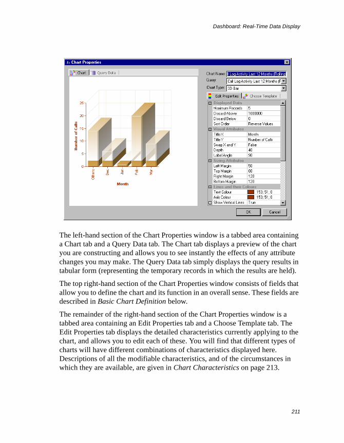
Dashboard: Real-Time Data Display
211
The left-hand section of the Chart Properties window is a tabbed area containing a Chart tab and a Query Data tab. The Chart tab displays a preview of the chart you are constructing and allows you to see instantly the effects of any attribute changes you may make. The Query Data tab simply displays the query results in tabular form (representing the temporary records in which the results are held).
The top right-hand section of the Chart Properties window consists of fields that allow you to define the chart and its function in an overall sense. These fields are described in Basic Chart Definition below.
The remainder of the right-hand section of the Chart Properties window is a tabbed area containing an Edit Properties tab and a Choose Template tab. The Edit Properties tab displays the detailed characteristics currently applying to the chart, and allows you to edit each of these. You will find that different types of charts will have different combinations of characteristics displayed here. Descriptions of all the modifiable characteristics, and of the circumstances in which they are available, are given in Chart Characteristics on page 213.
Dashboard: Real-Time Data Display
212
The Choose Template tab in the Chart Properties window displays a list of chart templates from which you can select one to make a whole set of characteristics apply to the chart instantly. You may wish to experiment with different templates to see if any are suitable for you. If you find one with a style that is quite close to what you want, you can fine-tune the characteristics in the Edit Properties tab.
To save all the changes you have made in the Chart Properties window, you must click OK. The window then closes and your changes are applied to the chart (whether displayed in a pane or not).
Basic Chart Definition
The overall definition of the chart is given by the following attributes:
Chart Name This is the title that appears at the top of the pane in which the chart is displayed, and should clearly state what information the chart is meant to convey.
Query This specifies the query whose results are to be displayed on the chart. The following queries are available:
• Call Log Activity Last 12 Months (Rolling)
• Call Log Activity Last 24 Hours (Rolling)
• Call Log Activity Last 31 Days (Rolling)
• Call Log Activity Last 7 Days (Rolling)
• Number of Escalated Calls by Customer
• Number of Escalated Calls by Site
• Number of Open Calls by Status Logged This Month
• Number of Open Calls by Status Logged This Week
• Number of Open Calls by Status Logged This Year
• Number of Open Calls by Status Logged Today
• Number of Open Calls by Status
• Top Ten Calling Customers This Month
• Top Ten Calling Customers This Week
• Top Ten Calling Customers This Year
Dashboard: Real-Time Data Display
213
• Top Ten Calling Customers Today
• Top Ten Calling Sites This Month
• Top Ten Calling Sites This Week
• Top Ten Calling Sites This Year
• Top Ten Calling Sites Today
• Top Ten Problem Types This Month
• Top Ten Problem Types This Week
• Top Ten Problem Types This Year
• Top Ten Problem Types Today
Chart Type This defines the type of chart to be displayed. You can select any of the following chart types:
• Pie chart
• 3D pie chart
• Bar chart
• 3D bar chart
• Line graph
• 3D line graph
• Area graph
• 3D area graph
Chart Characteristics
The Edit Properties tab in the Chart Properties window allows you to alter many of the visual characteristics of the chart, and to place limits on the data to be displayed. Although most of the characteristics available for alteration are common to all types of chart, and will always be displayed in the tab, some will be visible only for certain chart types. In the descriptions of the characteristics given below (grouped by category), the circumstances under which the latter will be available are clearly stated.
To enter values for these attributes, you either (as appropriate) type/edit the required text, or click in the attribute field to reveal a drop-down list (or some other control), from which you then make a selection. On making a change in a
Dashboard: Real-Time Data Display
214
type/edit field, you have to press Return or click outside that field to see the effect of your change in the preview area.
Displayed Data
The characteristics in this category relate to the data to be presented in the chart, and apply to all chart types.
Maximum Records This specifies the maximum number of result records that are to be included in the statistics for the chart display (where the actual records are those listed in the Query Data tab).
Discard Above This attribute allow items with too high a count (in comparison with the majority) to be excluded from the chart. This is useful when a few items having counts far in excess of the norm are seen to adversely affect chart readability, or when such items simply do not need to be compared with the others. If you wish to exclude high counts, type the required threshold value in this field.
Discard Below This attribute allow items with too low a count (in comparison with the majority) to be excluded from the chart. This is useful when a few items having counts far below the norm are seen to adversely affect chart readability, or when such items simply do not need to be compared with the others. If you wish to exclude low counts, type the required threshold value in this field.
Sort Order This defines the kind of sorting that should apply to the items shown on the chart. For a bar chart, line graph or area graph, the items are ordered by default from left to right (or from bottom to top), while for a pie chart, the default ordering is clockwise. The following kinds of sorting are available:
Default Values This option gives the chart items a fairly random distribution, as they are placed in the order in which the data is read from the database.
Reverse Values This option places the chart items in an order that is the reverse of the Default Values order.
Values Ascending This option places the chart items in ascending order, based on the count for each item.
Values Descending This option places the chart items in descending order, based on the count for each item.
Dashboard: Real-Time Data Display
215
Label Ascending This option places the chart items in ascending alphanumerical order, based on the label text.
Label Descending This option places the chart items in descending alphanumerical order, based on the label text.
Staggered Values This option places the chart items in an order of “alternating opposites”. The placing starts with the item that has the highest count, followed by the item with the lowest count. Then, the items with the next-highest and next-lowest counts are placed, and so on. This kind of distribution is most useful in pie charts where overlapping of item labels would otherwise occur due to adjacent segments being too thin.
Visual Attributes
The characteristics in this category relate to various aspects of how the chart is presented visually.
Title X This applies to bar charts, line graphs and area graphs. It defines a title for the X-axis of the chart.
Title Y This applies to bar charts, line graphs and area graphs. It defines a title for the Y-axis of the chart.
Swap X and Y This applies to bar charts, line graphs and area graphs. Selection of True will switch over the X- and Y-axes of the chart. Selection of False will switch these back to their default positions.
Depth This is specific to 3D charts. It defines, in pixels, the depth of the chart graphic (that is, along the Z-axis). For a multi-depth pie chart, it would define the maximum depth (or “height”) of the pie.
Multi Depth This is specific to 3D pie charts. When set to True, it causes each segment of the pie to be displayed with a different depth, dropping by equal increments from maximum depth at the start angle in a clockwise direction. The respective depths therefore have no significance apart from a stylistic one.
Label Angle This applies to bar charts, line graphs and area graphs. It specifies the angle (in degrees) that the label text should make with the X-axis.
Perspective This is specific to 3D pie charts. It defines the apparent angle of view (in degrees) that the observer has of the pie, with 0 being the top view and
Dashboard: Real-Time Data Display
216
90 being the side view. Note that true perspective is not automatically maintained, as the pie’s depth is controlled independently of the angle.
Start Angle This is specific to pie charts. It defines, in degrees (relative to “12 o’clock”), the angle at which segment ordering begins, being the place in the pie where the starting edge of the first segment is located.
Use Explode Mode This option is specific to pie charts. When enabled, it causes a specific segment to be set apart from the remainder of the pie.
Explode Segment For a pie chart, this specifies the segment to be exploded. It is expressed in terms of a clockwise count of segments, beginning with 0 at the start angle.
Explode Distance For a pie chart, this specifies the distance (in pixels) by which the exploded segment is to be separated from the rest of the pie.
Show Legend This is specific to pie charts. For such a chart, it is possible to display a colour-coded legend to augment its presentation. To enable the legend, set this attribute to True.
Legend Left For a pie chart, if you enter an appropriate value (in pixels, measured relative to the left-hand edge of the chart pane), you can position the legend horizontally anywhere within the pane.
Legend Top For a pie chart, if you enter an appropriate value (in pixels, measured relative to the top edge of the chart pane), you can position the legend vertically anywhere within the pane.
Sizing Attributes
The characteristics in this category govern the size of the chart within its pane.
Left Margin This applies to bar charts, line graphs and area graphs. It defines, in pixels, the left margin of the chart, as measured between the left-hand edge of the pane and the Y-axis of the chart (that is, ignoring all labels). Thus, as you increase the size of the left margin, the chart’s width is reduced from the left.
Top Margin This applies to bar charts, line graphs and area graphs. It defines, in pixels, the top margin of the chart, as measured between the top edge of the pane and the corresponding edge of the chart graphic. Thus, as you increase the size of the top margin, the chart’s height is reduced from the top.
Dashboard: Real-Time Data Display
217
Right Margin This applies to bar charts, line graphs and area graphs. It defines, in pixels, the right margin of the chart, as measured between the right-hand edge of the pane and the corresponding edge of the chart graphic. Thus, as you increase the size of the right margin, the chart’s width is reduced from the right.
Bottom Margin This applies to bar charts, line graphs and area graphs. It defines, in pixels, the bottom margin of the chart, as measured between the bottom edge of the pane and the X-axis of the chart (that is, ignoring all labels). Thus, as you increase the size of the bottom margin, the chart’s height is reduced from the bottom.
Scaling Factor This applies to pie charts. It defines the “flat” diameter of the pie, expressed as a percentage of the smaller dimension of the chart pane.
Lines and their Colours
The characteristics in this category relate to the various kinds of lines that can be displayed in the chart space.
Text Colour This determines the colour of all label text.
Axis Colour This determines the colour of the two axes on bar charts, line graphs and area graphs.
Show Vertical Lines This option applies to bar charts, line graphs and area graphs. When set to True, it will cause vertical grid lines to be displayed.
Vertical Line Colour This determines the colour of the vertical grid lines on bar charts, line graphs and area graphs. You select the colour by clicking the drop-down list to reveal a colour chart in which you then click the required colour.
Show Horizontal Lines This option applies to bar charts, line graphs and area graphs. When set to True, it will cause horizontal grid lines to be displayed.
Horizontal Line Colour This determines the colour of the horizontal grid lines on bar charts, line graphs and area graphs. You select the colour by clicking the drop-down list to reveal a colour chart in which you then click the required colour.
Show Edge This option applies to bar charts, line graphs and area graphs. When set to True, it will cause the lines defining the edges of the chart graphic to be displayed.
Dashboard: Real-Time Data Display
218
Edge Colour This determines the colour of the lines defining the edges of the chart graphic on bar charts, line graphs and area graphs. You select the colour by clicking the drop-down list to reveal a colour chart in which you then click the required colour.
Show Boundaries This option applies to pie charts. When set to True, it will cause the lines defining the segment boundaries to be displayed.
Boundary Colour This determines the colour of the segment boundaries on pie charts. You select the colour by clicking the drop-down list to reveal a colour chart in which you then click the required colour.
Object Fill
The characteristics in this category govern the different stylistic ways in which the chart elements can be colour-filled.
Fill Type This applies to bar charts, pie charts and area graphs. It defines the colouring mode of the chart elements, of which there are three to choose from:
Default Palette With this option, which applies to bar charts and pie charts only, each element is filled with a different colour from the palette provided.
Plain Colour This option specifies that all chart elements be filled with a single colour of constant tone. The Fill Colour attribute (see below) would specify the actual colour.
Gradient This option applies to bar charts and area graphs. It specifies that all chart elements be filled with a single colour of gradually changing tone. The Fill Colour attribute (see below) would specify the actual colour.
Fill Colour This specifies the colour to be used for the Plain Colour and Gradient types of fill. You select the colour by clicking the drop-down list to reveal a colour chart in which you then click the required colour.
Element Transparency This option, when set to True, will make the chart’s grid lines and normally hidden parts of chart elements visible through all those elements that overlap them.
Transparency Level This option specifies the precise degree of transparency that will apply to all chart elements. The available values are in the range 0 to 255, where 0 is totally opaque and 255 is fully transparent.
Dashboard: Real-Time Data Display
219
Background
The characteristics in this category govern the different stylistic ways in which the chart background can be coloured.
Background Type This defines the colouring style of the chart pane’s background, of which there are three to choose from:
Plain Colour This option specifies the colouring style of the chart pane’s background as being constant-tone and opaque. The Background Plain Colour attribute (see below) would specify the actual colour.
Gradient This option specifies the colouring style of the chart pane’s background as an opaque one with repeating gradients. The Background Gradient attribute (see below) would specify the actual colour.
Transparent This option specifies the colouring style of the chart pane’s background as colourless, which effectively means white.
Background Plain Colour This specifies the colour to be used for the Plain Colour type of background. You select the colour by clicking the drop-down list to reveal a colour chart in which you then click the required colour.
Background Gradient This specifies the colour to be used for the Gradient type of background. You can choose from the following:
• Gold
• Silver
• Red Metal
• Blue Metal
• Green Metal
Deleting a ChartIf you simply wish to make a chart disappear from a particular pane but still retain it within the pool, you should clear the pane as described in Switching to a Different or Null Chart in a Pane on page 209.
However, if you actually want to remove a chart altogether from the pool, you should first ensure that it is displayed in one of the panes. Then, you have to

Dashboard: Real-Time Data Display
220
right-click in that pane and select Delete Chart from the context menu that pops up. At the confirmation prompt, click Yes. The chart’s details are then removed from your local swdbconf.xml file.
Operator Scripts
221
Operator Scripts
Note The Operator Scripts feature is not available in Supportworks Essentials.
The Operator Scripts feature allows suitably authorised users to build, within Supportworks, a wizard-run system of troubleshooting scripts, which may include a certain amount of call-logging data-entry functionality. Once such a system has been built, analysts will be able, when scripts are run, to follow guided, decision-tree questioning on-screen as they speak to customers on the phone. Not only can the question-led scripts yield suggested resolutions to commonly encountered problems, but, at the end of script execution, the entire sequence of questions asked and answers given can be automatically logged in the problem-description field of the Log Call form. In addition, questions asking for information that analysts would normally be expected to enter in edit fields of the Log Call form can be included in scripts to provide a wizard-orientated way of completing much of the form.
The inherent ease with which the troubleshooting interface made available by Operator Scripts allows basic problems to be solved makes it particularly suitable for first-line or newly recruited support staff. It allows inexperienced staff to achieve higher fix rates at the first support level, and therefore reduces the number of calls that have to be passed to a higher level. Even if the troubleshooter fails to resolve a problem, the details of the initial process of elimination will have been recorded instantly in the call diary (without any need for typing), ready for the next line of support to pick up.
What Operator Scripts ContainOperator scripts, being fundamentally concerned with troubleshooting, are problem-profile-specific, which means that they would each be assigned to a particular profile. Basically, the script you would create for any given problem profile would consist of a series of “questions” relating to that problem, each presented in a format dependent on the nature of the question. Branching on
Operator Scripts
222
multiple-choice questions would be achieved by associating each possible answer with the appropriate question to follow. For questions that do not generate branches, the sequence is determined by simply indicating, within each question’s properties, what the next question should be.
Apart from strictly troubleshooting types of questions, a script can also contain questions that request information intended to go into edit fields in the Log Call form, or those that are not questions at all, but announcements not requiring an answer.
There are, broadly, four types of questions you can include in scripts:
• Information entry. This kind of question prompts the analyst to type textual or numerical data, such as the customer’s name, in an edit field. Textual data is alphanumeric and can be either single-line or multi-line. When creating such a question, you can choose whether or not the data input by the analyst is to be placed into the Log Call form and, if so, into which edit field on that form.
• Single-item selection. This is a multiple-choice kind of question in which only one answer is allowed. The mechanism for selecting the answer can be a drop-down list, a set of horizontally arranged radio buttons, or a set of vertically arranged radio buttons. When creating such a question, you would normally link each radio-button choice with a subsequent question relating to that answer, thus allowing you to build entire troubleshooting sequences.
• Multi-item selection. This is a multiple-choice kind of question in which more than one answer is allowed. The mechanism for selecting the answers can be a tabular list, a set of horizontally arranged checkboxes, or a set of vertically arranged checkboxes. Multi-item answers cannot be processed by the system in any way, so they would be used primarily as checklists just for the benefit of the analyst.
• Announcements. These are simply statements, directed at the analyst, that do not need an answer (other than a button click to continue). Although you can have such statements anywhere in the script, they are most appropriate at the beginning of the script, and when defined as exit points at the ends of sequences.
When creating a new question within a script, you can base it on a template containing the required typed-input format, a predefined multiple-choice set, or no answer mechanism at all. Alternatively, you could build all aspects of the question from scratch.
Operator Scripts
223
For an information-entry type of question, there are templates available that offer all three of the possible typed-input formats:
• Single-line text input
• Multi-line text input
• Numeric input
For single-item selection, the predefined multiple-choice sets available per selection mechanism are as follows:
• Yes/No
• Yes/No/Don’t Know
• True/False
• Rating (Very Poor to Excellent)
• Rating (1 to 5)
For multi-item selection, the predefined multiple-choice sets are:
• 2 choice items
• 3 choice items
• 4 choice items
• 5 choice items
For announcements, you can choose from the following predefined texts:
• Wizard introduction
• Wizard completion
How Operator Scripts Are UsedAn operator script is invoked whenever an analyst, during the process of logging a call, selects a problem profile for that call on the Log Call form. The profile concerned will have been assigned that script beforehand.
The script executes in the form of a troubleshooting wizard, each of whose pages would display a single question, with Back, Next and Cancel buttons at the bottom. Typically, the first page would be a brief introduction to the wizard concerned, indicating the nature of the problem to be investigated, and inviting
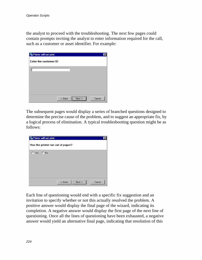
Operator Scripts
224
the analyst to proceed with the troubleshooting. The next few pages could contain prompts inviting the analyst to enter information required for the call, such as a customer or asset identifier. For example:
The subsequent pages would display a series of branched questions designed to determine the precise cause of the problem, and to suggest an appropriate fix, by a logical process of elimination. A typical troubleshooting question might be as follows:
Each line of questioning would end with a specific fix suggestion and an invitation to specify whether or not this actually resolved the problem. A positive answer would display the final page of the wizard, indicating its completion. A negative answer would display the first page of the next line of questioning. Once all the lines of questioning have been exhausted, a negative answer would yield an alternative final page, indicating that resolution of this
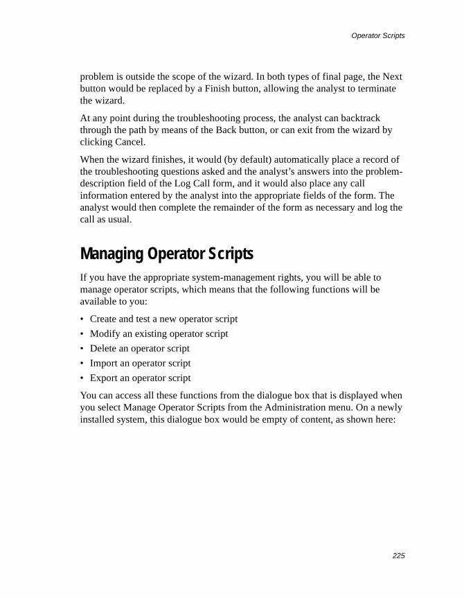
Operator Scripts
225
problem is outside the scope of the wizard. In both types of final page, the Next button would be replaced by a Finish button, allowing the analyst to terminate the wizard.
At any point during the troubleshooting process, the analyst can backtrack through the path by means of the Back button, or can exit from the wizard by clicking Cancel.
When the wizard finishes, it would (by default) automatically place a record of the troubleshooting questions asked and the analyst’s answers into the problem-description field of the Log Call form, and it would also place any call information entered by the analyst into the appropriate fields of the form. The analyst would then complete the remainder of the form as necessary and log the call as usual.
Managing Operator ScriptsIf you have the appropriate system-management rights, you will be able to manage operator scripts, which means that the following functions will be available to you:
• Create and test a new operator script
• Modify an existing operator script
• Delete an operator script
• Import an operator script
• Export an operator script
You can access all these functions from the dialogue box that is displayed when you select Manage Operator Scripts from the Administration menu. On a newly installed system, this dialogue box would be empty of content, as shown here:
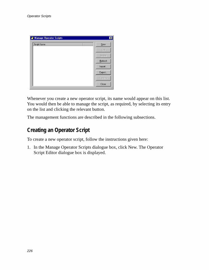
Operator Scripts
226
Whenever you create a new operator script, its name would appear on this list. You would then be able to manage the script, as required, by selecting its entry on the list and clicking the relevant button.
The management functions are described in the following subsections.
Creating an Operator Script
To create a new operator script, follow the instructions given here:
1. In the Manage Operator Scripts dialogue box, click New. The Operator Script Editor dialogue box is displayed.
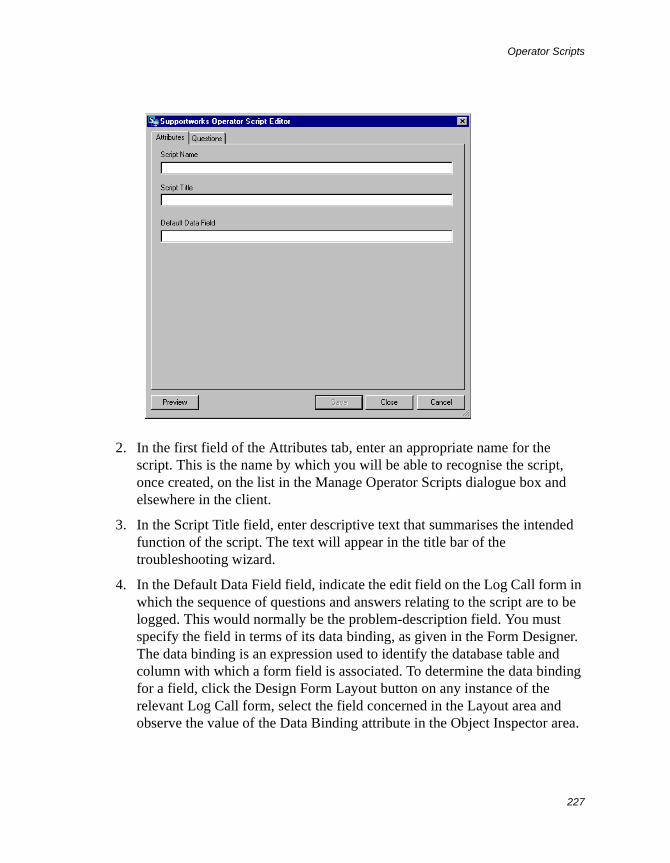
Operator Scripts
227
2. In the first field of the Attributes tab, enter an appropriate name for the script. This is the name by which you will be able to recognise the script, once created, on the list in the Manage Operator Scripts dialogue box and elsewhere in the client.
3. In the Script Title field, enter descriptive text that summarises the intended function of the script. The text will appear in the title bar of the troubleshooting wizard.
4. In the Default Data Field field, indicate the edit field on the Log Call form in which the sequence of questions and answers relating to the script are to be logged. This would normally be the problem-description field. You must specify the field in terms of its data binding, as given in the Form Designer. The data binding is an expression used to identify the database table and column with which a form field is associated. To determine the data binding for a field, click the Design Form Layout button on any instance of the relevant Log Call form, select the field concerned in the Layout area and observe the value of the Data Binding attribute in the Object Inspector area.
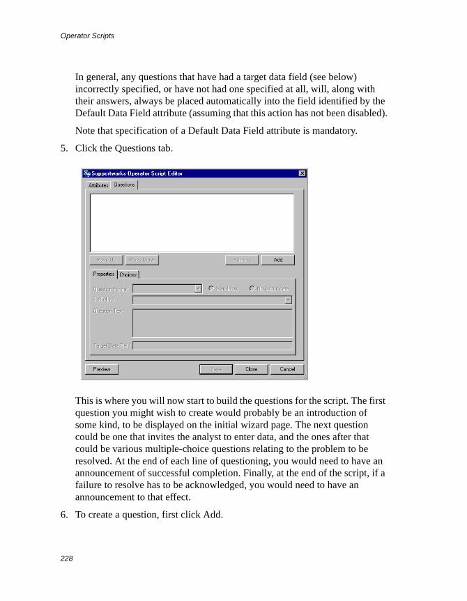
Operator Scripts
228
In general, any questions that have had a target data field (see below) incorrectly specified, or have not had one specified at all, will, along with their answers, always be placed automatically into the field identified by the Default Data Field attribute (assuming that this action has not been disabled).
Note that specification of a Default Data Field attribute is mandatory.
5. Click the Questions tab.
This is where you will now start to build the questions for the script. The first question you might wish to create would probably be an introduction of some kind, to be displayed on the initial wizard page. The next question could be one that invites the analyst to enter data, and the ones after that could be various multiple-choice questions relating to the problem to be resolved. At the end of each line of questioning, you would need to have an announcement of successful completion. Finally, at the end of the script, if a failure to resolve has to be acknowledged, you would need to have an announcement to that effect.
6. To create a question, first click Add.
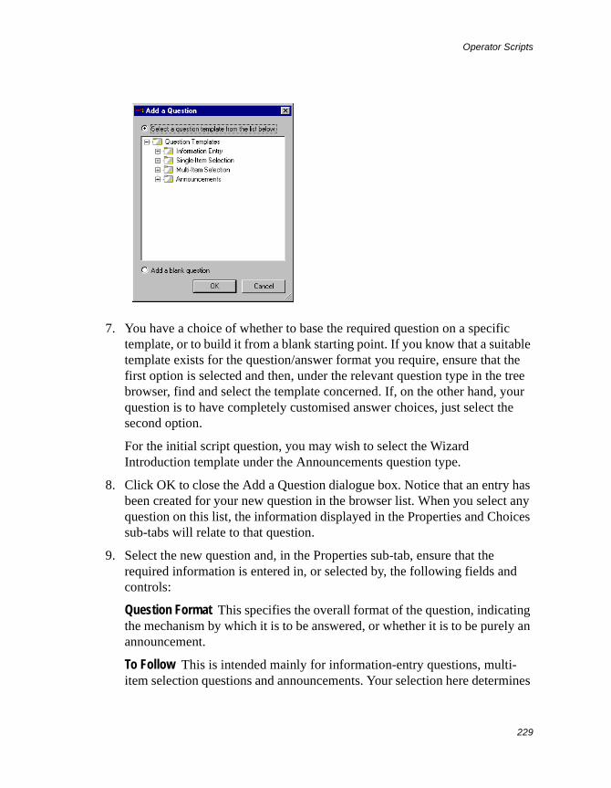
Operator Scripts
229
7. You have a choice of whether to base the required question on a specific template, or to build it from a blank starting point. If you know that a suitable template exists for the question/answer format you require, ensure that the first option is selected and then, under the relevant question type in the tree browser, find and select the template concerned. If, on the other hand, your question is to have completely customised answer choices, just select the second option.
For the initial script question, you may wish to select the Wizard Introduction template under the Announcements question type.
8. Click OK to close the Add a Question dialogue box. Notice that an entry has been created for your new question in the browser list. When you select any question on this list, the information displayed in the Properties and Choices sub-tabs will relate to that question.
9. Select the new question and, in the Properties sub-tab, ensure that the required information is entered in, or selected by, the following fields and controls:
Question Format This specifies the overall format of the question, indicating the mechanism by which it is to be answered, or whether it is to be purely an announcement.
To Follow This is intended mainly for information-entry questions, multi-item selection questions and announcements. Your selection here determines
Operator Scripts
230
the question, if any, that is to be displayed (on a wizard page) immediately after this one. If you leave the setting as the generic default “-----Next Question-----”, the next question displayed on the wizard will literally be the question immediately below this one on the browser list. However, when you are creating a single-item selection question, the meaning of “-----Next Question-----” here changes to now indicate that the following question will depend on the analyst’s choice (see step 11 below).
If you are creating a new question for a new script, you will not be able initially to specify the next question, as none will yet exist. However, once you have actually created the next question, if you come back to this one, you will find that you will now be able to make the required selection. For a single-item-selection kind of question, if you actually specify a particular following question here, this will prevail over any specified for an individual choice.
If you are creating a question that is to be displayed (with a Finish button) on one of the final pages of the wizard, you must select the generic item “-----End-----”.
Question Text This determines the text of the question.
Target Data Field This can apply to any type of question that requires an answer but would normally be used just for information-entry question types. It specifies the edit field on the Log Call form into which the answer to the question is to be placed. Note that only the answer would go into the edit field.
You specify the field in terms of its data binding, as given in the Form Designer. The data binding is an expression used to identify the database table and column with which a form field is associated. To determine the data binding for a field, click the Design Form Layout button on any instance of the relevant Log Call form, select the field concerned in the Layout area and observe the value of the Data Binding attribute in the Object Inspector area.
Note that if you fail to specify a target data field for a question requiring an answer (or you specify it incorrectly), and you have not enabled the “No output data” option (see below), both the question and the answer will be placed by default into the edit field identified by the script’s Default Data Field attribute. Thus, if you want analysts’ troubleshooting sequences to be
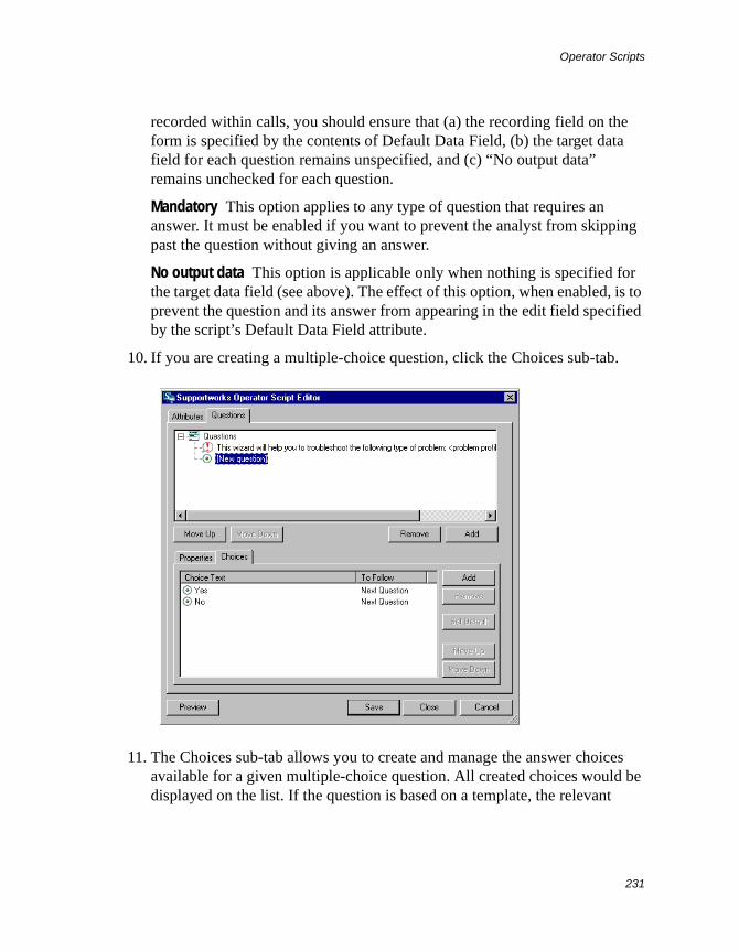
Operator Scripts
231
recorded within calls, you should ensure that (a) the recording field on the form is specified by the contents of Default Data Field, (b) the target data field for each question remains unspecified, and (c) “No output data” remains unchecked for each question.
Mandatory This option applies to any type of question that requires an answer. It must be enabled if you want to prevent the analyst from skipping past the question without giving an answer.
No output data This option is applicable only when nothing is specified for the target data field (see above). The effect of this option, when enabled, is to prevent the question and its answer from appearing in the edit field specified by the script’s Default Data Field attribute.
10. If you are creating a multiple-choice question, click the Choices sub-tab.
11. The Choices sub-tab allows you to create and manage the answer choices available for a given multiple-choice question. All created choices would be displayed on the list. If the question is based on a template, the relevant
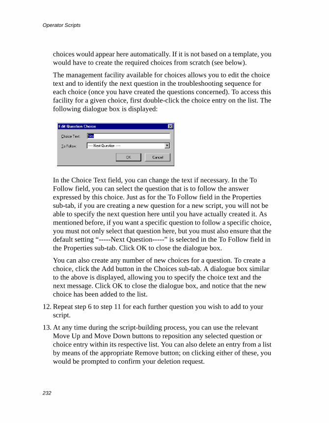
Operator Scripts
232
choices would appear here automatically. If it is not based on a template, you would have to create the required choices from scratch (see below).
The management facility available for choices allows you to edit the choice text and to identify the next question in the troubleshooting sequence for each choice (once you have created the questions concerned). To access this facility for a given choice, first double-click the choice entry on the list. The following dialogue box is displayed:
In the Choice Text field, you can change the text if necessary. In the To Follow field, you can select the question that is to follow the answer expressed by this choice. Just as for the To Follow field in the Properties sub-tab, if you are creating a new question for a new script, you will not be able to specify the next question here until you have actually created it. As mentioned before, if you want a specific question to follow a specific choice, you must not only select that question here, but you must also ensure that the default setting “-----Next Question-----” is selected in the To Follow field in the Properties sub-tab. Click OK to close the dialogue box.
You can also create any number of new choices for a question. To create a choice, click the Add button in the Choices sub-tab. A dialogue box similar to the above is displayed, allowing you to specify the choice text and the next message. Click OK to close the dialogue box, and notice that the new choice has been added to the list.
12. Repeat step 6 to step 11 for each further question you wish to add to your script.
13. At any time during the script-building process, you can use the relevant Move Up and Move Down buttons to reposition any selected question or choice entry within its respective list. You can also delete an entry from a list by means of the appropriate Remove button; on clicking either of these, you would be prompted to confirm your deletion request.
Operator Scripts
233
14. When you are ready to test your script, click Save and then click Preview. The wizard for this script is invoked, allowing you to see exactly how it would work for an analyst. If the wizard does not work in the way you would expect, keep making changes to the script until you are satisfied with the results.
15. Once the script is usable, you must assign it to the appropriate problem profile if you want the wizard to execute from the Log Call form. For details of how to assign a script, see Viewing and Modifying an Existing Call Profile on page 86.
Modifying an Operator Script
To modify an existing operator script, select its entry from the list in the Manage Operator Scripts dialogue box and click Edit (or just double-click the entry). The Operator Script Editor is displayed, giving you access to all the attributes and contents of the script. See the section Creating an Operator Script on page 226 for information on what is available in this editor.
Deleting Operator Scripts
To delete one or more operator scripts, select their entries from the list in the Manage Operator Scripts dialogue box and click Delete. Then, at the confirmation prompt, click Yes.
Exporting and Importing Operator Scripts
If your organisation has more than one Supportworks system and you want to be able to use one system’s operator scripts on another, you can achieve that by means of appropriate export and import facilities. The export function saves operator scripts as an XML-formatted file, and the import function takes the content of any previously exported XML operator-script file and, from this, restores the original scripts.
To Export One or More Operator Scripts
You can export any number of existing operator scripts into a single XML file.
Operator Scripts
234
To export the scripts, select their entries from the list in the Manage Operator Scripts dialogue box and click Export. A standard Save As dialogue box is displayed. Select the required target location for the file, enter an appropriate name for it and click Save. The dialogue box closes and the file is created and placed in the chosen location, triggering the display of a confirmation message box. Click OK to close the box.
To Import One or More Operator Scripts
You would import operator scripts from an XML operator-script file that has previously been created by an export action.
To import a set of scripts, click Import in the Manage Operator Scripts dialogue box. A standard Open dialogue box is displayed. Find and select the relevant XML file, and click Open. The dialogue box closes and you should be able to see that entries corresponding to the restored scripts have appeared on the list in Manage Operator Scripts.
Customer Satisfaction Surveys
235
Customer Satisfaction Surveys
Note The Customer Surveys feature is not licensable for Supportworks Essentials.
The Customer Surveys feature is available on any Supportworks system that is licensed for it. This feature provides a transactional survey tool that allows you to create on-line questionnaires for any number of named customer-survey campaigns. Once you have created a questionnaire for a given survey, any of the team’s support analysts, when resolving or closing a call, can select an option to have the system automatically e-mail the customer with a URL link pointing to the chosen survey page, thus giving them the option to go to that page to complete the appropriate questionnaire. With each customer-survey campaign, you can measure how your support organisation is performing against customer expectations. If necessary, you can have several different campaigns running at the same time.
A questionnaire is normally displayed in the form of one question per page, although you can, if you wish, group together any number of (perhaps related) questions on a given page. If answer-dependent branching is not required at any point, you could have the entire questionnaire on a single page.
Each survey can be reported on at any time while it is active, allowing you to see instantly, in various different views (for example, a graphical one with charts), what answers your customers have given to your questions so far. A report view may contain, for example, a full display of every respondent’s answers, or perhaps a graphically presented display of respondent totals for all the answers to every statistically computable (that is, multiple-choice) question.
Questionnaire ConstituentsThe questionnaire you would create for any given survey would consist largely of a series of questions relating to that survey, each presented in a format dependent on the type of question. Branching on multiple-choice questions
Customer Satisfaction Surveys
236
would be achieved by associating each possible answer with the appropriate question to follow. For questions that do not generate branches, the sequence is determined by simply indicating, within each question’s properties, what the next question should be.
Apart from actual questions, a questionnaire can also contain statements that do not require an answer, and those that act as headers for groups of subsidiary questions or statements.
There are, broadly, four types of questions you can include in questionnaires:
• Information entry. This kind of question prompts the respondent to type textual or numerical data, such as their own name, in an edit field. Textual data is alphanumeric and can be single-line, multi-line or password. Password fields are the same as single-line text fields, except that the entered data is hidden by asterisks in the customary way.
• Single-item selection. This is a multiple-choice kind of question in which only one answer out of two or more alternatives is allowed. The mechanism for selecting the answer can be a drop-down list, a set of horizontally arranged radio buttons, or a set of vertically arranged radio buttons. When creating such a question, you would normally link each radio-button choice with a subsequent question relating to that answer, thus allowing you to branch the questionnaire at appropriate points.
• Multi-item selection. This is a multiple-choice kind of question in which more than one answer is allowed. The mechanism for selecting the answers can be a tabular list, a set of horizontally arranged checkboxes, or a set of vertically arranged checkboxes. Multi-item answers will not alter the flow of questions within the questionnaire.
• Announcements. These are simply statements, directed at the respondent, that do not need an answer (other than a link click to continue). Although you can have such statements anywhere in the questionnaire, they are perhaps most useful at the beginning of the questionnaire, and when defined as a questionnaire exit point at the end of each possible question sequence.
All types of questions can be grouped together as subsidiary questions within a “section”, a structure that consists of a general statement as its header (known as a “section header”), with a set of individual questions below it. The contents of a given section will always be displayed together on the same page. Thus, if you
Customer Satisfaction Surveys
237
wanted to construct a single-page questionnaire, you would have to create a section and include all the questions within that.
Any series of questions whose answer mechanisms are of the horizontally arranged radio-button or checkbox type, and which have a common set of answer choices, can be grouped together in a “matrix”, which is a tabular structure consisting of a general question or statement as its header (known as a “matrix header”), with a set of subsidiary questions below it. Typically, these subsidiary questions would qualify the main question (that is, the header) in some way, or divide it up into its constituents.
When creating a new question within a questionnaire, you can base it on a template containing the required typed-input format, a predefined multiple-choice set, or no answer mechanism at all. Alternatively, you could build all aspects of the question from scratch.
For an information-entry type of question, there are templates available that offer all four of the possible typed-input formats:
• Single-line text input
• Multi-line text input
• Password input
• Numeric input
For single-item selection, the predefined multiple-choice sets available per selection mechanism are as follows:
• Yes/No
• Yes/No/Don’t Know
• True/False
• Rating (Very Poor to Excellent)
• Rating (1 to 5)
For multi-item selection, the predefined multiple-choice sets are:
• 2 choice items
• 3 choice items
• 4 choice items
• 5 choice items
Customer Satisfaction Surveys
238
For announcements, you can choose from the following predefined texts:
• Survey introduction
• Survey completion (not normally needed, as a standard, fixed-text completion announcement will always be generated at the end of a survey)
For every question you create, of a type that requires an answer, you can choose whether or not it is to be included in the survey reports.
Questionnaire UsageWhenever a support analyst, during the process of resolving or closing a customer’s call, enables the “Send customer survey” option, then selects a named survey from the adjacent field’s drop-down list, and finally clicks Resolve Call or Close Call, an e-mail message is sent to that customer inviting them to take part in the survey. When the customer clicks the URL link provided in the message, their Web browser opens, displaying the first (or only) page of the relevant questionnaire.
On any given page, the respondent would see one or more questions, followed by a Continue link at the bottom. They would be expected to answer the question(s) on that page and then click Continue. Typically, the first question might be a brief introduction to the survey, and would invite the respondent to proceed.
The subsequent pages would display a series of questions designed to elicit the respondent’s opinion on your support team’s performance, or perhaps about some other issue. A typical multiple-choice question using vertically arranged radio buttons might be as follows:
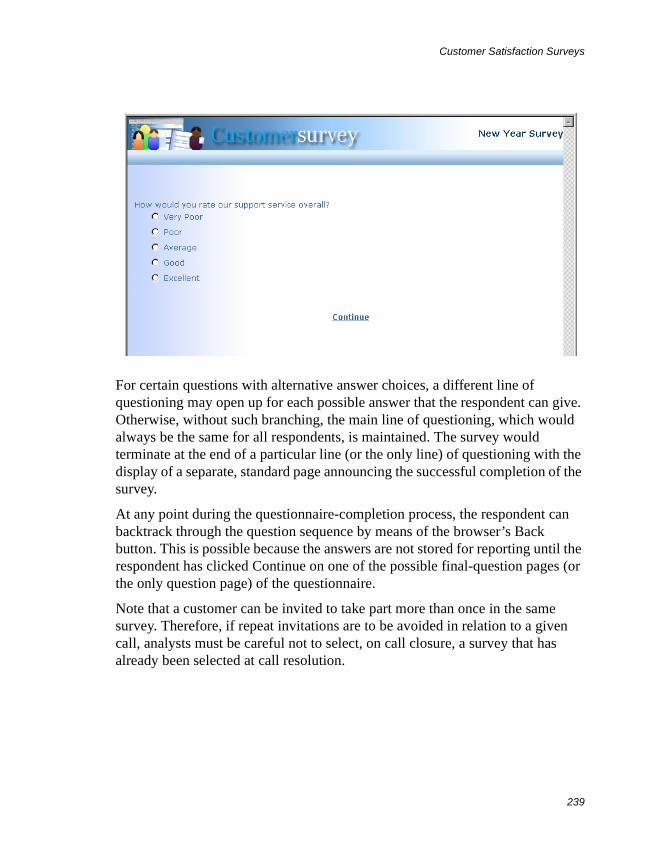
Customer Satisfaction Surveys
239
For certain questions with alternative answer choices, a different line of questioning may open up for each possible answer that the respondent can give. Otherwise, without such branching, the main line of questioning, which would always be the same for all respondents, is maintained. The survey would terminate at the end of a particular line (or the only line) of questioning with the display of a separate, standard page announcing the successful completion of the survey.
At any point during the questionnaire-completion process, the respondent can backtrack through the question sequence by means of the browser’s Back button. This is possible because the answers are not stored for reporting until the respondent has clicked Continue on one of the possible final-question pages (or the only question page) of the questionnaire.
Note that a customer can be invited to take part more than once in the same survey. Therefore, if repeat invitations are to be avoided in relation to a given call, analysts must be careful not to select, on call closure, a survey that has already been selected at call resolution.
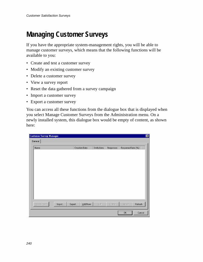
Customer Satisfaction Surveys
240
Managing Customer SurveysIf you have the appropriate system-management rights, you will be able to manage customer surveys, which means that the following functions will be available to you:
• Create and test a customer survey
• Modify an existing customer survey
• Delete a customer survey
• View a survey report
• Reset the data gathered from a survey campaign
• Import a customer survey
• Export a customer survey
You can access all these functions from the dialogue box that is displayed when you select Manage Customer Surveys from the Administration menu. On a newly installed system, this dialogue box would be empty of content, as shown here:
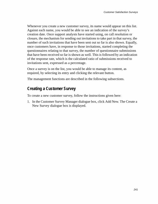
Customer Satisfaction Surveys
241
Whenever you create a new customer survey, its name would appear on this list. Against each name, you would be able to see an indication of the survey’s creation date. Once support analysts have started using, on call resolution or closure, the mechanism for sending out invitations to take part in that survey, the number of such invitations that have been sent out so far is also shown. Equally, once customers have, in response to those invitations, started completing the questionnaires relating to that survey, the number of questionnaire submissions that have been received so far is shown as well. This is followed by an indication of the response rate, which is the calculated ratio of submissions received to invitations sent, expressed as a percentage.
Once a survey is on the list, you would be able to manage its content, as required, by selecting its entry and clicking the relevant button.
The management functions are described in the following subsections.
Creating a Customer Survey
To create a new customer survey, follow the instructions given here:
1. In the Customer Survey Manager dialogue box, click Add New. The Create a New Survey dialogue box is displayed.
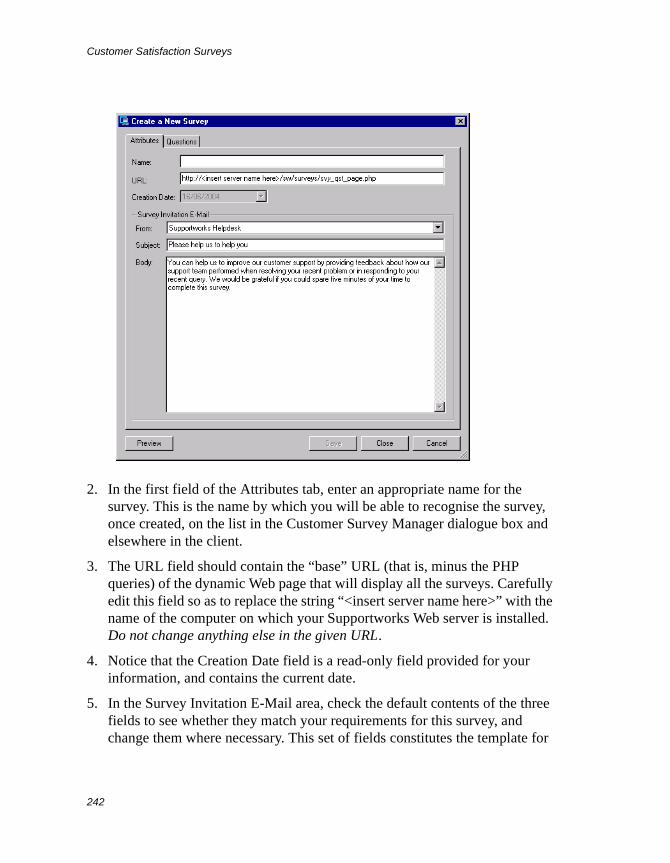
Customer Satisfaction Surveys
242
2. In the first field of the Attributes tab, enter an appropriate name for the survey. This is the name by which you will be able to recognise the survey, once created, on the list in the Customer Survey Manager dialogue box and elsewhere in the client.
3. The URL field should contain the “base” URL (that is, minus the PHP queries) of the dynamic Web page that will display all the surveys. Carefully edit this field so as to replace the string “<insert server name here>” with the name of the computer on which your Supportworks Web server is installed. Do not change anything else in the given URL.
4. Notice that the Creation Date field is a read-only field provided for your information, and contains the current date.
5. In the Survey Invitation E-Mail area, check the default contents of the three fields to see whether they match your requirements for this survey, and change them where necessary. This set of fields constitutes the template for
Customer Satisfaction Surveys
243
the e-mail messages that will be sent to customers inviting them to take part in the survey. The first field contains the originating mailbox, the second contains the subject line, and the third contains the text for the body of the message. In the subject and body-text fields, you can, if you wish, type the following variables:
• $analyst_name! to represent the name of the analyst resolving or closing the call
• $callref! to represent the relevant call reference
In the transmitted messages themselves, the full URL link to the Web page displaying the survey would be located below the body text defined in the template. If either or both of the above variables had been found in the template, these would be resolved to their current string values in the actual messages.
6. Click the Questions tab.
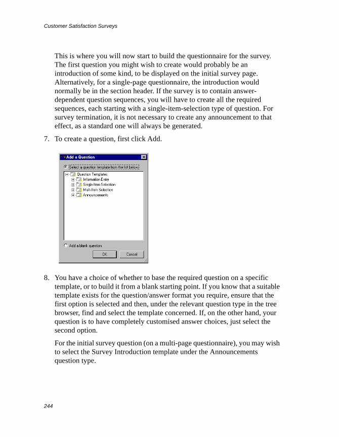
Customer Satisfaction Surveys
244
This is where you will now start to build the questionnaire for the survey. The first question you might wish to create would probably be an introduction of some kind, to be displayed on the initial survey page. Alternatively, for a single-page questionnaire, the introduction would normally be in the section header. If the survey is to contain answer-dependent question sequences, you will have to create all the required sequences, each starting with a single-item-selection type of question. For survey termination, it is not necessary to create any announcement to that effect, as a standard one will always be generated.
7. To create a question, first click Add.
8. You have a choice of whether to base the required question on a specific template, or to build it from a blank starting point. If you know that a suitable template exists for the question/answer format you require, ensure that the first option is selected and then, under the relevant question type in the tree browser, find and select the template concerned. If, on the other hand, your question is to have completely customised answer choices, just select the second option.
For the initial survey question (on a multi-page questionnaire), you may wish to select the Survey Introduction template under the Announcements question type.
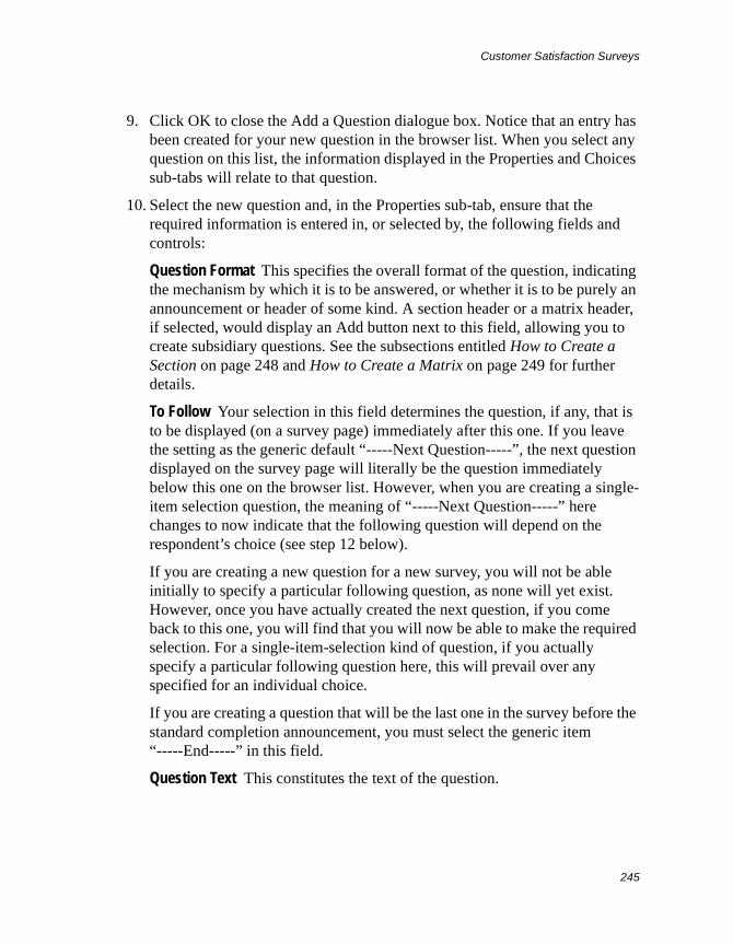
Customer Satisfaction Surveys
245
9. Click OK to close the Add a Question dialogue box. Notice that an entry has been created for your new question in the browser list. When you select any question on this list, the information displayed in the Properties and Choices sub-tabs will relate to that question.
10. Select the new question and, in the Properties sub-tab, ensure that the required information is entered in, or selected by, the following fields and controls:
Question Format This specifies the overall format of the question, indicating the mechanism by which it is to be answered, or whether it is to be purely an announcement or header of some kind. A section header or a matrix header, if selected, would display an Add button next to this field, allowing you to create subsidiary questions. See the subsections entitled How to Create a Section on page 248 and How to Create a Matrix on page 249 for further details.
To Follow Your selection in this field determines the question, if any, that is to be displayed (on a survey page) immediately after this one. If you leave the setting as the generic default “-----Next Question-----”, the next question displayed on the survey page will literally be the question immediately below this one on the browser list. However, when you are creating a single-item selection question, the meaning of “-----Next Question-----” here changes to now indicate that the following question will depend on the respondent’s choice (see step 12 below).
If you are creating a new question for a new survey, you will not be able initially to specify a particular following question, as none will yet exist. However, once you have actually created the next question, if you come back to this one, you will find that you will now be able to make the required selection. For a single-item-selection kind of question, if you actually specify a particular following question here, this will prevail over any specified for an individual choice.
If you are creating a question that will be the last one in the survey before the standard completion announcement, you must select the generic item “-----End-----” in this field.
Question Text This constitutes the text of the question.
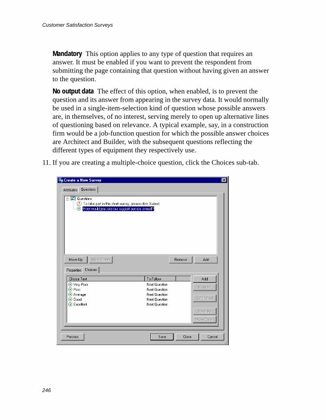
Customer Satisfaction Surveys
246
Mandatory This option applies to any type of question that requires an answer. It must be enabled if you want to prevent the respondent from submitting the page containing that question without having given an answer to the question.
No output data The effect of this option, when enabled, is to prevent the question and its answer from appearing in the survey data. It would normally be used in a single-item-selection kind of question whose possible answers are, in themselves, of no interest, serving merely to open up alternative lines of questioning based on relevance. A typical example, say, in a construction firm would be a job-function question for which the possible answer choices are Architect and Builder, with the subsequent questions reflecting the different types of equipment they respectively use.
11. If you are creating a multiple-choice question, click the Choices sub-tab.
Customer Satisfaction Surveys
247
12. The Choices sub-tab allows you to create and manage the answer choices available for a given multiple-choice question. All created choices would be displayed on the list. If the question is based on a template, the relevant choices would appear here automatically. If it is not based on a template, you would have to create the required choices from scratch (see below).
The management facility available for choices allows you to edit the choice text and to identify the next question in the sequence for each choice (once you have created the questions concerned). To access this facility for a given choice, first double-click the choice entry on the list. The following dialogue box is displayed:
In the Choice Text field, you can change the text if necessary. In the To Follow field, you can select the question that is to follow the answer expressed by this choice. Just as for the To Follow field in the Properties sub-tab, if you are creating a new question for a new survey, you will not be able to specify the next question until you have actually created it. As mentioned before, if you want a specific question to follow a specific choice, you must not only select that question here, but you must also ensure that the default setting “-----Next Question-----” is selected in the To Follow field in the Properties sub-tab. Click OK to close the dialogue box.
You can also create any number of new choices for a question. To create a choice, click the Add button in the Choices sub-tab. A dialogue box similar to the above is displayed, allowing you to specify the choice text and the next message. Click OK to close the dialogue box, and notice that the new choice has been added to the list.
13. Repeat step 8 to step 12 for each further question you wish to add to your questionnaire.
14. At any time during the questionnaire-building process, you can use the relevant Move Up and Move Down buttons to reposition any selected
Customer Satisfaction Surveys
248
question or choice entry within its respective list. You can also delete an entry from a list by means of the appropriate Remove button; on clicking either of these, you would be prompted to confirm your deletion request.
15. When you are ready to test your questionnaire, click Save and then click Preview. Your Web browser opens on the first survey page, allowing you to work through the questionnaire exactly the way a respondent would, but without any reportable data being saved. If the questionnaire does not work in the way you would expect, keep making changes to it until you are satisfied with the results. Note that, in preview mode, when you submit a terminating survey page, the survey-completion message will be prefixed with an indication that you are in that mode.
16. Once the questionnaire is usable, click Close and then OK.
17. When you are ready to launch your new survey campaign, remember to inform all relevant support analysts that the survey is available, so that they can start selecting it whenever they resolve or close a call. You will then have to wait for your customers to respond to the survey invitations.
How to Create a Section
You need to create a section whenever you want a number of questions (or all questions) in the survey to be displayed on the same page. A section starts off with, and is defined by, a section header, which is a special kind of question. Once you have created a section header, you will be able to proceed with the creation of its subsidiary questions.
The procedure for creating a section is as follows:
1. With the Questions tab of the Create a New Survey (or Survey Properties) dialogue box displayed, click Add to display the Add a Question dialogue box.
2. Select the “Add a blank question” option and click OK. Notice that a new question entry has been created in the browser list.
3. With that entry still highlighted, and the Properties sub-tab displayed, select Section Header in the Question Format field. Notice that an Add button has appeared, instead of the Mandatory option, next to this field.
Customer Satisfaction Surveys
249
4. If the section is to be on the last or only page of the questionnaire (before the standard survey-completion announcement), select “-----End-----” in the To Follow field. Otherwise, select a specific question or retain the generic “-----Next Question-----” setting, as required. In the case of a specific question, you may need to come back to this field later and make the selection if the question does not yet exist.
5. In the Question Text field, type the text you require for the section header.
6. With the section header highlighted, click the Add button next to the Question Format field. A subsidiary question entry appears as a child item beneath the section-header entry in the browser list.
7. With the subsidiary question highlighted, set its properties and, if appropriate, its answer choices in much the same way as for non-headed questions. Note, however, that, for a subsidiary question, branching is not allowed (whether answer-dependent or otherwise). Therefore, its following question will always be the next subsidiary question (if any) within the section.
8. Repeat the last two steps for each additional subsidiary question you wish to create.
You now have a new section in your questionnaire.
How to Create a Matrix
You would create a matrix in the survey whenever you want to group together various specific aspects of a general question that share the same set of possible predefined answers. A matrix starts off with, and is defined by, a matrix header, which (like a section header) is a special kind of question. Once you have created a matrix header, you will be able to proceed with the creation of its subsidiary questions. As is the case with a section, all the questions that make up a given matrix will be displayed on the same survey page.
The procedure for creating a matrix is as follows:
1. With the Questions tab of the Create a New Survey (or Survey Properties) dialogue box displayed, click Add to display the Add a Question dialogue box.
Customer Satisfaction Surveys
250
2. Select the “Add a blank question” option and click OK. Notice that a new question entry has been created in the browser list.
3. With that entry still highlighted, and the Properties sub-tab displayed, select Matrix Header in the Question Format field. Notice that an Add button has appeared, instead of the Mandatory option, next to this field.
4. If the matrix is to be on the last page of the questionnaire (before the standard survey-completion announcement), select “-----End-----” in the To Follow field. Otherwise, select a specific question or retain the generic “-----Next Question-----” setting, as required. In the case of a specific question, you may need to come back to this field later and make the selection if the question does not yet exist.
5. In the Question Text field, type the text you require for the matrix header.
6. Select the Choices sub-tab and use the Add button in that area to create each of the required answer choices for the matrix. This one set of choices will apply to all the subsidiary questions within the matrix. Note that it is not possible to define a following question for any matrix answer choice.
7. Return to the Properties sub-tab and, with the matrix header highlighted, click the Add button next to the Question Format field. A subsidiary question entry appears as a child item beneath the matrix-header entry in the browser list.
8. With the subsidiary question highlighted, set its properties in much the same way as for non-headed questions. Note, however, that, for a subsidiary question, branching is not allowed, which means that its following question will always be the next subsidiary question (if any) within the matrix. Note also that a subsidiary matrix question’s answer choices will be those defined in the header (see step 6 above).
9. Repeat the last two steps for each additional subsidiary question you wish to create.
You now have a new matrix in your questionnaire.
Modifying a Customer Survey
You can modify an existing customer survey at any time up till the moment when the first survey invitation is sent out. Once the campaign is underway, you
Customer Satisfaction Surveys
251
will obtain a warning message if you try to make changes to the survey, unless you first reset that campaign’s data, as described in Resetting the Data Gathered from Survey Campaigns on page 258. Until you have reset the data, the survey’s attributes and contents, although still viewable, will be read-only.
To modify (or just view) a customer survey, select its entry from the list in the Customer Survey Manager dialogue box and click Edit (or just double-click the entry). The Survey Properties dialogue box, which is effectively the same as the Create a New Survey dialogue box, is displayed, giving you access to all the attributes and contents of the survey concerned. See the section Creating a Customer Survey on page 241 for information on what is available in this dialogue box.
Deleting Customer Surveys
To delete one or more customer surveys, select their entries from the list in the Customer Survey Manager dialogue box and click Delete. Then, at the confirmation prompt, click Yes.
Viewing Survey Reports
Once at least one customer has responded to a particular survey, you can run a standard set of reports based on the data collected from it so far. The following reports are available:
• Full Report This displays, for every respondent in turn, the submitted answers to all the questions that the respondent was asked on the questionnaire they completed.
• List Respondents This displays a list of the customer IDs of all the respondents to the survey. From here, you can display, in the same format as the Full Report, the submitted answers to all the questions that a chosen respondent was asked.
• Graphical Report This displays, in chart form, for each multiple-choice question in turn, the number of respondents that have given each of the possible answers. You can modify the characteristics of each chart within the report in exactly the same way as for the charts found in normal Supportworks reports.
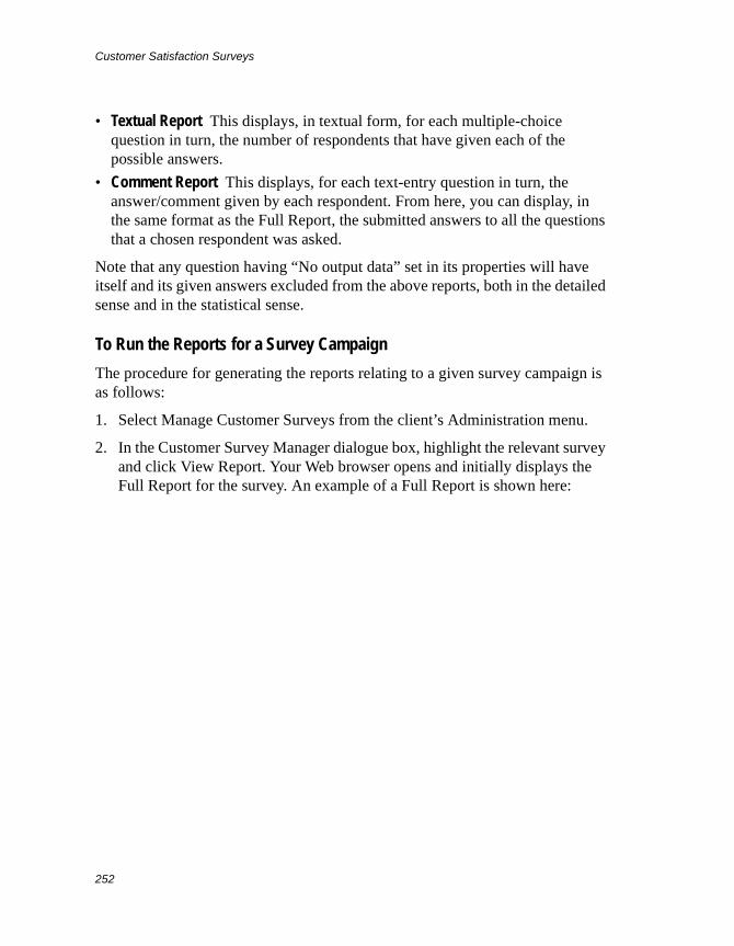
Customer Satisfaction Surveys
252
• Textual Report This displays, in textual form, for each multiple-choice question in turn, the number of respondents that have given each of the possible answers.
• Comment Report This displays, for each text-entry question in turn, the answer/comment given by each respondent. From here, you can display, in the same format as the Full Report, the submitted answers to all the questions that a chosen respondent was asked.
Note that any question having “No output data” set in its properties will have itself and its given answers excluded from the above reports, both in the detailed sense and in the statistical sense.
To Run the Reports for a Survey Campaign
The procedure for generating the reports relating to a given survey campaign is as follows:
1. Select Manage Customer Surveys from the client’s Administration menu.
2. In the Customer Survey Manager dialogue box, highlight the relevant survey and click View Report. Your Web browser opens and initially displays the Full Report for the survey. An example of a Full Report is shown here:
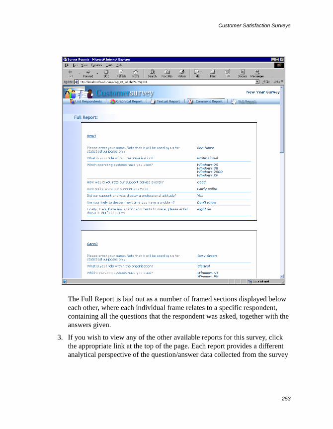
Customer Satisfaction Surveys
253
The Full Report is laid out as a number of framed sections displayed below each other, where each individual frame relates to a specific respondent, containing all the questions that the respondent was asked, together with the answers given.
3. If you wish to view any of the other available reports for this survey, click the appropriate link at the top of the page. Each report provides a different analytical perspective of the question/answer data collected from the survey
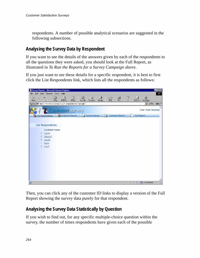
Customer Satisfaction Surveys
254
respondents. A number of possible analytical scenarios are suggested in the following subsections.
Analysing the Survey Data by Respondent
If you want to see the details of the answers given by each of the respondents to all the questions they were asked, you should look at the Full Report, as illustrated in To Run the Reports for a Survey Campaign above.
If you just want to see these details for a specific respondent, it is best to first click the List Respondents link, which lists all the respondents as follows:
Then, you can click any of the customer ID links to display a version of the Full Report showing the survey data purely for that respondent.
Analysing the Survey Data Statistically by Question
If you wish to find out, for any specific multiple-choice question within the survey, the number of times respondents have given each of the possible
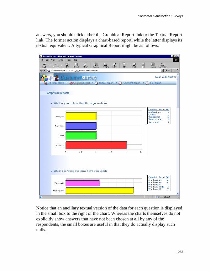
Customer Satisfaction Surveys
255
answers, you should click either the Graphical Report link or the Textual Report link. The former action displays a chart-based report, while the latter displays its textual equivalent. A typical Graphical Report might be as follows:
Notice that an ancillary textual version of the data for each question is displayed in the small box to the right of the chart. Whereas the charts themselves do not explicitly show answers that have not been chosen at all by any of the respondents, the small boxes are useful in that they do actually display such nulls.
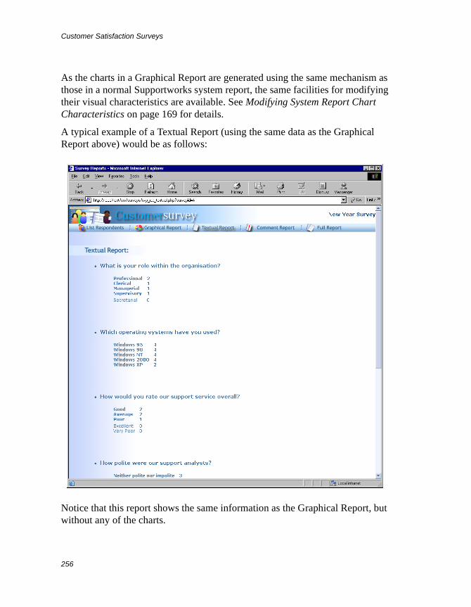
Customer Satisfaction Surveys
256
As the charts in a Graphical Report are generated using the same mechanism as those in a normal Supportworks system report, the same facilities for modifying their visual characteristics are available. See Modifying System Report Chart Characteristics on page 169 for details.
A typical example of a Textual Report (using the same data as the Graphical Report above) would be as follows:
Notice that this report shows the same information as the Graphical Report, but without any of the charts.
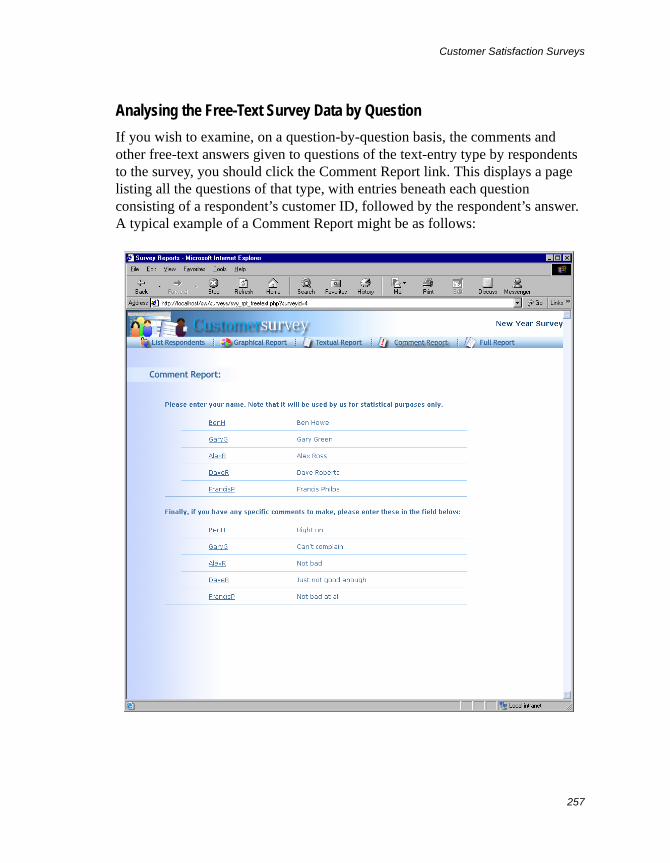
Customer Satisfaction Surveys
257
Analysing the Free-Text Survey Data by Question
If you wish to examine, on a question-by-question basis, the comments and other free-text answers given to questions of the text-entry type by respondents to the survey, you should click the Comment Report link. This displays a page listing all the questions of that type, with entries beneath each question consisting of a respondent’s customer ID, followed by the respondent’s answer. A typical example of a Comment Report might be as follows:
Customer Satisfaction Surveys
258
While you are looking at a particular respondent’s answer to a question, you may wish to quickly refer to that respondent’s answers to the multiple-choice questions in the same survey. If that is the case, all you need to do is click the relevant customer ID link, and a version of the Full Report will be displayed, showing the survey data for that respondent. You can then click Back to return to the Comment Report.
Resetting the Data Gathered from Survey Campaigns
If, once a specific survey campaign is underway, you discover a mistake in the questionnaire associated with it, you will want to correct this immediately. However, if you then try, from within the Customer Survey Manager, to open the survey for editing, a warning message will be displayed, pointing out that survey invitations have been sent out and that the survey cannot be modified.
The only way to overcome this is to reset the data for that survey. The data concerned would consist not only of the actual answers given by respondents to the survey (which are stored in the database), but also of the running totals of the number of invitations sent out and the number of questionnaires submitted, together with the figure for the survey response rate.
To reset the data, simply select the relevant survey from the list in the Customer Survey Manager dialogue box and click Reset. Then, at the confirmation prompt, click Yes. You will immediately notice that all figures shown within the listed survey entry are now set back to zero, and you will find that all the report data is deleted. If you now click Edit, you will no longer obtain the warning message, and you will be free to modify the survey.
Exporting and Importing Customer Surveys
If your organisation has more than one Supportworks system and you want to be able to use one system’s customer surveys on another, you can achieve that by means of appropriate export and import facilities. The export function saves customer surveys as an XML-formatted file, and the import function takes the content of any previously exported XML survey file and, from that, restores the original surveys.
Customer Satisfaction Surveys
259
The data exported to XML files will consist purely of the survey attributes and questions. Respondent data gathered from the survey campaign will not be included in the export.
To Export One or More Customer Surveys
You can export any number of existing customer surveys into a single XML file.
To export the surveys, select their entries from the list in the Customer Survey Manager dialogue box and click Export. A standard Save As dialogue box is displayed. Select the required target location for the file, enter an appropriate name for it and click Save. The dialogue box closes and the file is created and placed in the chosen location, triggering the display of a confirmation message box. Click OK to close the box.
To Import One or More Customer Surveys
You would import customer surveys from an XML survey file that has previously been created by an export action.
To import a set of surveys, click Import in the Customer Survey Manager dialogue box. A standard Open dialogue box is displayed. Find and select the relevant XML file, and click Open. The dialogue box closes and you should be able to see that entries corresponding to the restored surveys have appeared on the list in the Customer Survey Manager.

Customer Satisfaction Surveys
260
On-Line Customer Access to Your Helpdesk
261
On-Line Customer Access to Your Helpdesk
If your support phone lines are continually swamped with incoming calls, you may wish there were some alternative means by which your customers could contact the helpdesk without tying down valuable analysts unnecessarily. In fact, Supportworks provides two ways in which you can allow your customers to access your helpdesk system directly:
• By Auto Responder e-mail commands (if supported)
• By means of the Web-based SelfService application
Both methods are described in this chapter.
Auto Responder E-Mail Commands
Note These are not supported on Supportworks Essentials systems.
When your customers communicate with you by e-mail, not only can they tell you about their problems, but they can interact directly with your helpdesk system by typing a relevant command in the Subject (or some other) field. The Auto Responder mechanism (in conjunction with the E-Mail Routing Rules mechanism) would recognise this as an Auto Responder command and would invoke an appropriate action, invariably accompanied by a suitable response to the customer.
Messages containing Auto Responder commands would normally be submitted to the helpdesk using the same e-mail address as any other messages in which customers might be requesting support. If you have a multiple-mailbox Supportworks system, a customer would need to address command messages to the shared mailbox that belongs to the support section dealing with that customer.
On-Line Customer Access to Your Helpdesk
262
There are five Auto Responder commands that the system recognises by default, and these are as follows:
? logcall This command will automatically log a call on the system. The body of the message will be treated just like the text in the problem-description field of a Log Call form. The class, assign group, SLA and problem profile for the call will assume the defaults configured for this command (in the Log New Call rule). The status of the call will be Unassigned. The ability of a customer to use this command is governed by an option you can set in the Control tab of Customer Properties.
? updatecall Fnnnnnnn This command will automatically update the specified call (which must relate to the customer concerned). The body of the message will be treated just like the text in the action-description field of an Update Call form. The ability of a customer to use this command is governed by another option you can set in the Control tab of Customer Properties.
? callstatus Fnnnnnnn This command will generate a mailback report containing the publicly enabled contents of the call diary for the specified call (which must relate to the customer concerned). The call is identified by the argument Fnnnnnnn, which is the call reference number. The leading zeroes in the call reference number may be omitted. The ability of a customer to use this command is governed by yet another option you can set in the Control tab of Customer Properties.
? opencalls This command will generate a mailback report containing a list of currently open calls relating to the customer.
? webpassword This command will generate a mailback response containing the customer’s SelfService password.
Your Supportworks system may have been configured with additional Auto Responder commands, and/or perhaps the default commands may have been renamed, in accordance with your organisation’s requirements. For example, there may be variants of a command that respectively generate differently worded sets of responses (perhaps in different languages), depending on the mailbox to which a message containing that command is addressed.
You can see which commands are valid on your system by reference to the E-Mail Auto Responder tab in the Supportworks server configuration.
On-Line Customer Access to Your Helpdesk
263
Note that Auto Responder e-mail commands are not case-sensitive, and that (in the case of the default commands) a space is always required after the ? character. Note also that e-mail messages containing valid Auto Responder commands are always intercepted by the system before they have a chance to reach the intended mailbox, and they would therefore never be visible in the shared mail view.
Auto Responder E-Mail Templates
When the system receives a command via e-mail, it immediately mails an appropriate response back to the sender. All such responses are based on pre-built templates that you can customise to suit your organisation’s preferences, although they are perfectly usable as supplied if you are using the default command processes. Before you publicise the Auto Responder commands, you should check that the templates are suitable. If they are not, you should edit them accordingly, as described in the section entitled Viewing and Editing Existing E-Mail Templates on page 133.
The default Auto Responder e-mail templates supplied with Supportworks are used as the basis of the e-mail messages sent to customers in response to their e-mail commands to log calls, to update calls, to access information about their currently open support calls, and to obtain their SelfService passwords. A response may be a confirmation of the received command, a rejection of the command, or an appropriate mailback containing the information requested by the command. There are nine specific types of response template supported for the default commands:
• Confirmation of Logged Call
• Rejection Response to Logged Call
• Confirmation of Call Update
• Rejection Response to Call Update
• Call Status Report
• Open Calls Summary
• No Open Calls Response to Summary Request
• Response to Web Password Request
• Rejection Response to Any Information Request
On-Line Customer Access to Your Helpdesk
264
Each Supportworks shared mailbox has its own set of such response templates, which means that the response to a command message sent to one mailbox may be completely different to the response to the same command message sent to another.
Testing the Auto Responder E-Mail Commands
If you wish to demonstrate the Auto Responder facility to yourself before publicising the commands available, please refer to the appropriate chapter of the template-specific Administrator Guide.
Configuring the Auto Responder
You can make changes to existing Auto Responder commands, create new commands and delete commands by using the facilities available in the E-Mail Auto Responder tab of the Supportworks server configuration.
In the configuration, each Auto Responder command is represented as a rule with a number of properties, one of which specifies the name of that command and its expected location within the message. Other important properties include the names of the e-mail templates that are to be used for the automated replies to the command message, as well as the name of the mailbox whose address is to be used as the source address in those replies.
As every Auto Responder command is linked to the VPME process that executes it, appropriate parameter mappings to that process are also included among the properties – one set relating to the generation of positive responses (OK Action) and another relating to the generation of rejections (Fail Action).
For more details, please refer to the relevant chapter of the Supportworks Server Configuration Guide.
The Web-Based SelfService ApplicationThe SelfService Web-server application is an optional feature of Supportworks that allows supported customers to log, track and update calls to your helpdesk over the World Wide Web, and also to remotely search your KnowledgeBase. Your customers log into a specially provided helpdesk area of your website,
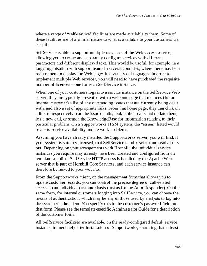
On-Line Customer Access to Your Helpdesk
265
where a range of “self-service” facilities are made available to them. Some of these facilities are of a similar nature to what is available to your customers via e-mail.
SelfService is able to support multiple instances of the Web-access service, allowing you to create and separately configure services with different parameters and different displayed text. This would be useful, for example, in a large organisation with support teams in several countries, where there may be a requirement to display the Web pages in a variety of languages. In order to implement multiple Web services, you will need to have purchased the requisite number of licences – one for each SelfService instance.
When one of your customers logs into a service instance on the SelfService Web server, they are typically presented with a welcome page that includes (for an internal customer) a list of any outstanding issues that are currently being dealt with, and also a set of appropriate links. From that home page, they can click on a link to respectively read the issue details, look at their calls and update them, log a new call, or search the KnowledgeBase for information relating to their particular problem. On a Supportworks ITSM system, the “issues” listed would relate to service availability and network problems.
Assuming you have already installed the Supportworks server, you will find, if your system is suitably licensed, that SelfService is fully set up and ready to try out. Depending on your arrangements with Hornbill, the individual service instances you require may already have been created and configured from the template supplied. SelfService HTTP access is handled by the Apache Web server that is part of Hornbill Core Services, and each service instance can therefore be linked to your website.
From the Supportworks client, on the management form that allows you to update customer records, you can control the precise degree of call-related access on an individual-customer basis (just as for the Auto Responder). On the same form, for internal customers logging into SelfService, you can choose the means of authentication, which may be any of those used by analysts to log into the system via the client. You specify this in the customer’s password field on that form. Please see the template-specific Administrator Guide for a description of the customer form.
All SelfService facilities are available, on the ready-configured default service instance, immediately after installation of Supportworks, assuming that at least
On-Line Customer Access to Your Helpdesk
266
one such instance of SelfService is included in your system’s licence. However, before you go ahead and publicise the URL of the SelfService Web server, you should first test the default service instance from the customer’s perspective, then tailor the Web pages that customers will see in accordance with the identity and requirements of your helpdesk, as well as suitably configure the default parameters that are to apply to customers’ self-logged calls. If you wish to offer more than one Web service, you must create them and repeat the configuration process for each of those instances. See the following subsections to find out how to perform all these actions.
A technical account of how SelfService works is given in Appendix E: How SelfService Works on page 323.
Testing the Default SelfService Instance
If you wish to demonstrate the SelfService facility to yourself, before publicising it, to see what may need changing, please refer to the appropriate chapter of the template-specific Administrator Guide.
Managing SelfService Configurations
Every Supportworks installation includes, subject to licensing, at least one ready-built instance of the SelfService application (appropriate to the template purchased), complete with a default configuration. If you have tested SelfService, you will have seen what the default service looks like, and you will probably have some idea of what text and what aspects of functionality you will need to modify to suit your particular helpdesk. The Manage SelfService Configurations function will allow you to carry out exactly that kind of configuration. It will also allow you, if you have purchased the requisite number of licences, to set up multiple SelfService instances, each with a different configuration.
Configuring a SelfService Instance: Settings
The first set of parameters that you will wish to configure for a SelfService instance includes website-specific settings, log-call settings, functional options and the customer table to use for look-up. To configure these settings for a given service, follow the instructions given here:
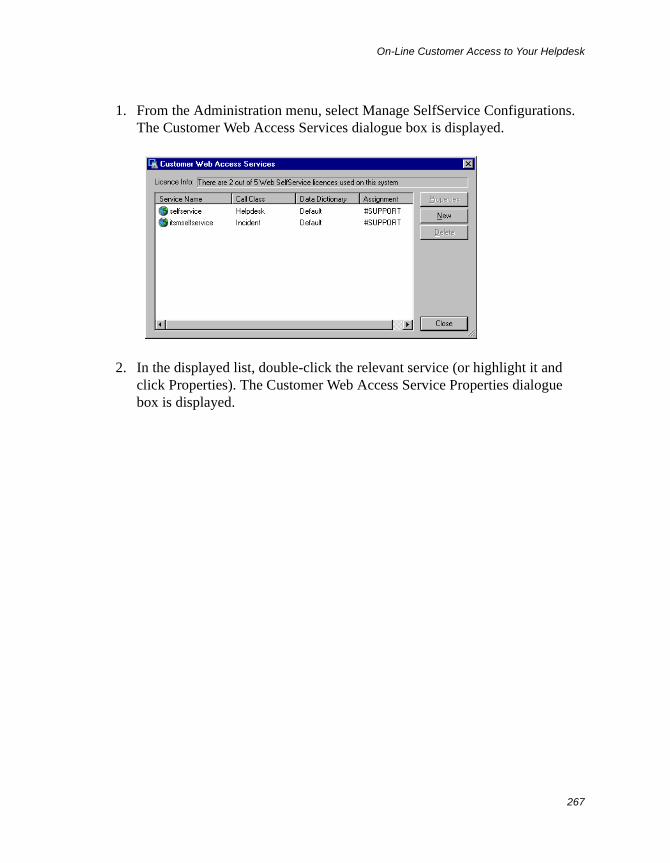
On-Line Customer Access to Your Helpdesk
267
1. From the Administration menu, select Manage SelfService Configurations. The Customer Web Access Services dialogue box is displayed.
2. In the displayed list, double-click the relevant service (or highlight it and click Properties). The Customer Web Access Service Properties dialogue box is displayed.
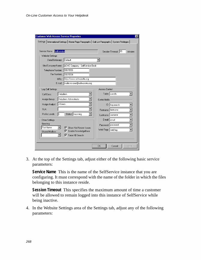
On-Line Customer Access to Your Helpdesk
268
3. At the top of the Settings tab, adjust either of the following basic service parameters:
Service Name This is the name of the SelfService instance that you are configuring. It must correspond with the name of the folder in which the files belonging to this instance reside.
Session Timeout This specifies the maximum amount of time a customer will be allowed to remain logged into this instance of SelfService while being inactive.
4. In the Website Settings area of the Settings tab, adjust any of the following parameters:
On-Line Customer Access to Your Helpdesk
269
Data Dictionary In Supportworks, a data dictionary is a customisation repository that holds a given set of field/column display names, drop-down list item names, and so on, that the application can use. Although these names normally apply to the client, some of them may also be used on the SelfService pages. You can specify which particular name set is to be used on those pages by selecting the appropriate data dictionary here.
Site/Company Name This specifies the text that will appear in the header of each Web page for this SelfService instance, on the right (and also within the contact information on the Help page). The name of your organisation and/or helpdesk would normally be appropriate here.
Telephone Number This specifies your helpdesk’s telephone number as it is to appear within the contact information on the Help page.
Fax Number This specifies your helpdesk’s fax number as it is to appear within the contact information on the Help page.
URL This specifies your helpdesk’s Web address as it is to appear within the contact information on the Help page.
E-mail This specifies your helpdesk’s e-mail address as it is to appear within the contact information on the Help page.
5. In the Log Call Settings area of the Settings tab, adjust any of the following parameters:
Call Class This determines the class of every call that will be logged via this SelfService instance. It therefore identifies the specific call forms (and possibly the call-action forms) that are to be displayed by the system when analysts properly log, examine or progress such calls using the Supportworks client.
Assign Group This specifies the analyst group to which all calls logged via this SelfService instance will be initially assigned.
Assign Analyst This specifies the analyst to which all calls logged via this SelfService instance will be initially assigned. Specification of an analyst is optional. You can only specify an analyst who belongs to the group you have specified.
SLA This determines the SLA for every call that will be logged via this SelfService instance.
On-Line Customer Access to Your Helpdesk
270
Profile Levels This specifies the maximum depth down to which SelfService users will be able to select a problem profile on the call-logging page.
Status This determines the status that every call logged via this SelfService instance will initially assume. If you select Incoming, the call status, as displayed in a call list, will literally be Incoming. This means that such calls will still need to be internally logged by analysts before they can be progressed further. If you select Logged and you did not specify an analyst for assignment, the call status will be Unassigned. If you select Logged and you did specify an analyst for assignment, the call status will be Unaccepted. Selecting Logged for the status means that the calls will already be internally logged when they enter the system, and will need no further logging by analysts.
6. In the Other Settings area of the Settings tab, adjust any of the following parameters:
Greeting This specifies the form of welcome greeting to be used at the top of the SelfService home page. You can select either a first-name or full-name greeting.
Shared Mailbox This specifies the shared mailbox from whose address the e-mail messages informing customers of their forgotten passwords are to be sent.
Show Hot/Known Issues If this option is enabled, issues marked as being publicly viewable will be displayed in the Noticeboard section of the SelfService home page. The customer will see these as a summary list of items, where the full details of each item can be displayed by means of a mouse-click. Note that this setting is only used on Supportworks applications that support Hot and Known Issues.
Enable KnowledgeBase If this option is enabled, customers will be allowed to search the KnowledgeBase from the SelfService pages.
Force KnowledgeBase Search If this option is enabled, the customer, when attempting to log a call, will first be diverted to a KnowledgeBase search page. This gives them a chance to possibly find the answer to their problem on their own, and thereby further reduce your support team’s workload.
7. If you want to change the database table that the system uses to look up information on customers logging into the service, you will need to adjust
On-Line Customer Access to Your Helpdesk
271
the parameters in the Access Control area of the Settings tab. First select the required table (which is userdb by default) from the drop-down list of the Table field, and then select the columns in this table that contain the information to be referenced (that is, the customer IDs, first names, last names, e-mail addresses, passwords and SelfService access rights). The relevant columns for userdb are as follows:
Customer ID: keysearchFirst Name: firstnameLast Name: surnameE-mail: emailPassword: passwordRights: webflag
8. When you have finished configuring the Settings tab, click Apply.
9. If you have finished configuring the service, click OK.
Configuring a SelfService Instance: International Settings
The second set of parameters that you may need to configure for a SelfService instance relate to the locale of the customers logging into the service concerned. These regional settings specify the customer’s time zone and also the format in which the date/time is to be displayed on the SelfService pages. To configure these settings for a given service, follow the instructions given here:
1. Display the Customer Web Access Service Properties dialogue box, as instructed in Configuring a SelfService Instance: Settings on page 266 above.
2. Select the International Settings tab.
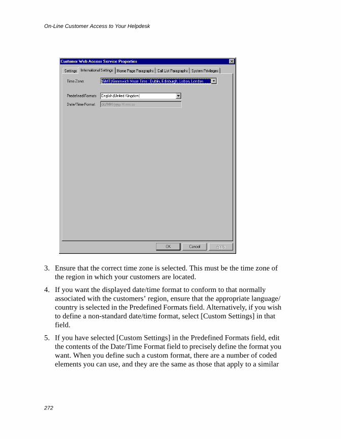
On-Line Customer Access to Your Helpdesk
272
3. Ensure that the correct time zone is selected. This must be the time zone of the region in which your customers are located.
4. If you want the displayed date/time format to conform to that normally associated with the customers’ region, ensure that the appropriate language/country is selected in the Predefined Formats field. Alternatively, if you wish to define a non-standard date/time format, select [Custom Settings] in that field.
5. If you have selected [Custom Settings] in the Predefined Formats field, edit the contents of the Date/Time Format field to precisely define the format you want. When you define such a custom format, there are a number of coded elements you can use, and they are the same as those that apply to a similar
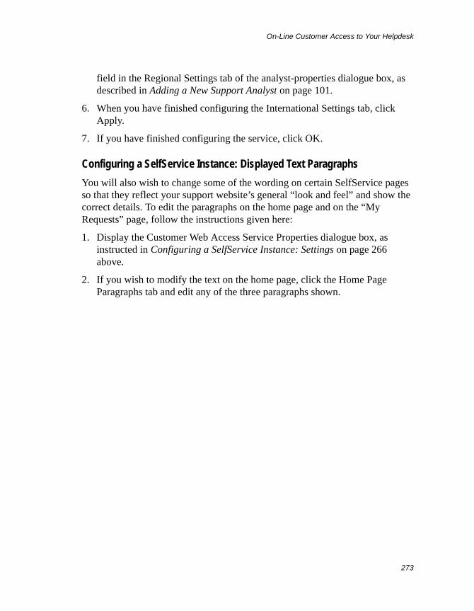
On-Line Customer Access to Your Helpdesk
273
field in the Regional Settings tab of the analyst-properties dialogue box, as described in Adding a New Support Analyst on page 101.
6. When you have finished configuring the International Settings tab, click Apply.
7. If you have finished configuring the service, click OK.
Configuring a SelfService Instance: Displayed Text Paragraphs
You will also wish to change some of the wording on certain SelfService pages so that they reflect your support website’s general “look and feel” and show the correct details. To edit the paragraphs on the home page and on the “My Requests” page, follow the instructions given here:
1. Display the Customer Web Access Service Properties dialogue box, as instructed in Configuring a SelfService Instance: Settings on page 266 above.
2. If you wish to modify the text on the home page, click the Home Page Paragraphs tab and edit any of the three paragraphs shown.
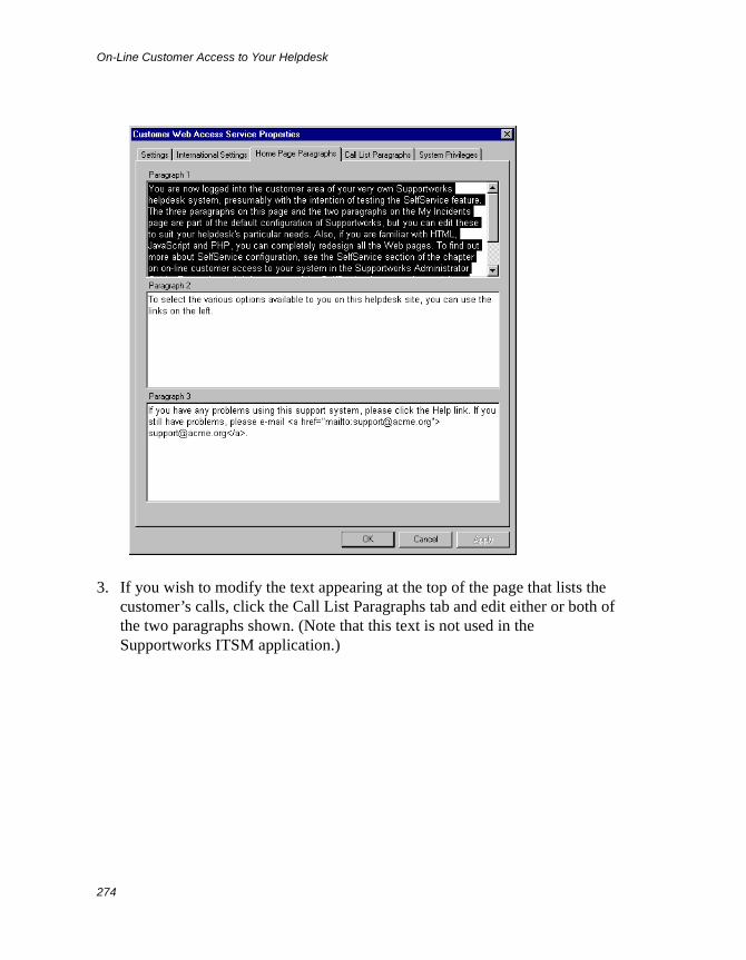
On-Line Customer Access to Your Helpdesk
274
3. If you wish to modify the text appearing at the top of the page that lists the customer’s calls, click the Call List Paragraphs tab and edit either or both of the two paragraphs shown. (Note that this text is not used in the Supportworks ITSM application.)
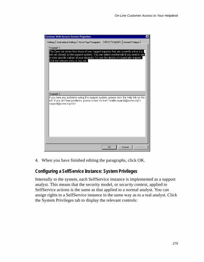
On-Line Customer Access to Your Helpdesk
275
4. When you have finished editing the paragraphs, click OK.
Configuring a SelfService Instance: System Privileges
Internally to the system, each SelfService instance is implemented as a support analyst. This means that the security model, or security context, applied to SelfService actions is the same as that applied to a normal analyst. You can assign rights to a SelfService instance in the same way as to a real analyst. Click the System Privileges tab to display the relevant controls:
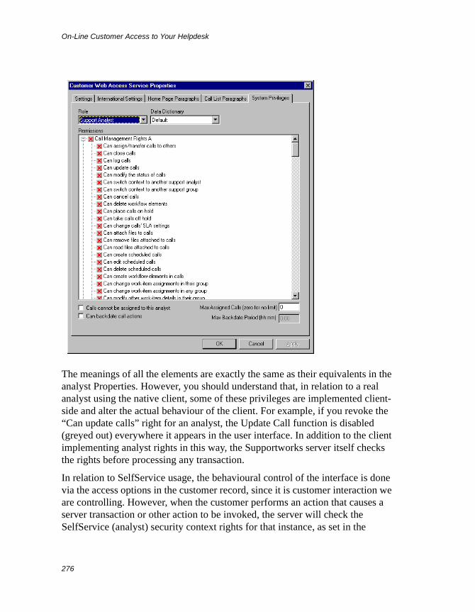
On-Line Customer Access to Your Helpdesk
276
The meanings of all the elements are exactly the same as their equivalents in the analyst Properties. However, you should understand that, in relation to a real analyst using the native client, some of these privileges are implemented client-side and alter the actual behaviour of the client. For example, if you revoke the “Can update calls” right for an analyst, the Update Call function is disabled (greyed out) everywhere it appears in the user interface. In addition to the client implementing analyst rights in this way, the Supportworks server itself checks the rights before processing any transaction.
In relation to SelfService usage, the behavioural control of the interface is done via the access options in the customer record, since it is customer interaction we are controlling. However, when the customer performs an action that causes a server transaction or other action to be invoked, the server will check the SelfService (analyst) security context rights for that instance, as set in the
On-Line Customer Access to Your Helpdesk
277
System Privileges tab of Customer Web Access Service Properties, to determine whether or not the action is allowed.
You should be aware that, currently, the server checks rights only in the following categories out of the total available on the tab:
• Call Management Rights A
• Call Management Rights B
• Database Management Rights against the Open/Closed Call and Customer tables
Thus, all rights settings other than the above will have no effect on SelfService. The reason why the rights nevertheless remain listed in their entirety is because, as functionality is developed further, as additional rights are added and as server-side checking of security rights is further refined, SelfService functionality will not inadvertently be disabled.
Creating a New SelfService Instance
If your installation is licensed for more than one SelfService instance, you can create and configure the permitted number of additional services straightaway. If, however, you require additional services but you do not have the appropriate licences, you should contact Hornbill, from whom you will be able to purchase these. Once you have obtained your new licence key, you should apply it in the usual way, and you can then proceed with the creation of the extra services.
To create and set up a new SelfService instance, follow the instructions given here:
1. Display the Customer Web Access Services dialogue box, as instructed in Configuring a SelfService Instance: Settings on page 266 above.
2. In that dialogue box, click New.
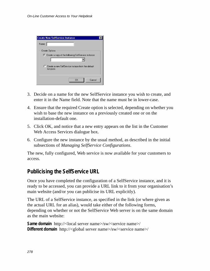
On-Line Customer Access to Your Helpdesk
278
3. Decide on a name for the new SelfService instance you wish to create, and enter it in the Name field. Note that the name must be in lower-case.
4. Ensure that the required Create option is selected, depending on whether you wish to base the new instance on a previously created one or on the installation-default one.
5. Click OK, and notice that a new entry appears on the list in the Customer Web Access Services dialogue box.
6. Configure the new instance by the usual method, as described in the initial subsections of Managing SelfService Configurations.
The new, fully configured, Web service is now available for your customers to access.
Publicising the SelfService URL
Once you have completed the configuration of a SelfService instance, and it is ready to be accessed, you can provide a URL link to it from your organisation’s main website (and/or you can publicise its URL explicitly).
The URL of a SelfService instance, as specified in the link (or where given as the actual URL for an alias), would take either of the following forms, depending on whether or not the SelfService Web server is on the same domain as the main website:
Same domain http://<local server name>/sw/<service name>/Different domain http://<global server name>/sw/<service name>/

On-Line Customer Access to Your Helpdesk
279
where <local server name> would be the intra-domain name of the computer on which the Supportworks Web-server environment is installed, <global server name> would be the fully qualified DNS name of that computer, and <service name> would be the name of the SelfService instance concerned.

On-Line Customer Access to Your Helpdesk
280
Managing Analyst Access to the Helpdesk
281
Managing Analyst Access to the Helpdesk
This chapter defines the two kinds of user licences that are available for analyst access to Supportworks. It describes how (on systems other than Supportworks Essentials) you can select analysts for usage of the Web-browser interfaces via one of these licence types, and how (on Supportworks Essentials systems) the system itself allocates licences of the other type for native-client usage.
Analyst Access LicensingThere is the possibility that any given user may be logged into more than one session simultaneously, which becomes more likely with Web-browser interface use. Conversely, there is the question of efficient usage of Supportworks when you are limited to a fixed number of concurrent sessions. This means that certain licensing issues need to be considered.
There are, basically, two kinds of user licence associated with Supportworks. The first is a concurrent licence, which is actually the standard user licence that allows any mixture of native-client and Web-browser interface usage up to the maximum number purchased. With that kind of licence, all multiple simultaneous login sessions in which a given user is engaged will count towards the total available. At the same time, though, concurrent licences allow the total number of users (if some usage is intermittent) to exceed the number of licences available.
The second type of user licence is a named licence, which is separate from, and may be additional to, the concurrent licences. Named licences would normally apply to Web-browser interfaces, except in Supportworks Essentials, where only named licences are available. Named licences are cheaper than concurrent licences, and (on systems other than Supportworks Essentials) allow named analysts to be logged into Web-browser interface sessions at the same time as being logged into native client sessions without using up any more of the valuable concurrent licences. (With Supportworks Essentials, named licences
Managing Analyst Access to the Helpdesk
282
allow multiple native-client login sessions per analyst to exist simultaneously, while using up only a single licence.) Note that a given named licence will apply only to the analyst nominated to use it, which means that the total number of possible named users will be strictly limited to the number of named licences you have purchased.
If (on a non-Essentials system) you have purchased named licences, and you wish to take advantage of these, you will need to nominate the analysts who are going to use them. The requisite procedure is given in the next section.
As far as licensing is concerned (again, on a non-Essentials system), the Supportworks server treats all Web-browser interface login sessions in exactly the same way, whether they are Analyst Portal or PDA Web Client sessions. Thus, a given named licence would apply to either of these kinds of login session.
Note Concurrent licences are assigned to client sessions from a “pool”. When you log out of a session that was assigned a licence from that pool, the licence is immediately returned back to the pool ready for use by another analyst logging into the system. In other words, the licence is not freed up until you have logged out of your session. Whenever you finish using the system via the Web in particular, it is all too easy to forget to log out. Merely closing the Web browser will leave the licence assigned to that session for four hours.
On a Supportworks Essentials system, the system allocates the named licences automatically. This happens whenever an analyst record is created.
Nominating Analysts for Named Licence Usage
Note This section applies to named Web-browser interface licences, so you can ignore it if only concurrent user licences exist on your Supportworks system, or if your system is Supportworks Essentials.
If you have named licences available, you can free up an equivalent number of your valuable concurrent licences by nominating, as named-licence users, all
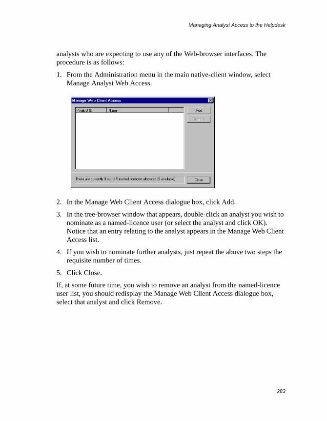
Managing Analyst Access to the Helpdesk
283
analysts who are expecting to use any of the Web-browser interfaces. The procedure is as follows:
1. From the Administration menu in the main native-client window, select Manage Analyst Web Access.
2. In the Manage Web Client Access dialogue box, click Add.
3. In the tree-browser window that appears, double-click an analyst you wish to nominate as a named-licence user (or select the analyst and click OK). Notice that an entry relating to the analyst appears in the Manage Web Client Access list.
4. If you wish to nominate further analysts, just repeat the above two steps the requisite number of times.
5. Click Close.
If, at some future time, you wish to remove an analyst from the named-licence user list, you should redisplay the Manage Web Client Access dialogue box, select that analyst and click Remove.

Managing Analyst Access to the Helpdesk
284
Analyst Rights and Default Settings
285
Appendix A Analyst Rights and Default Settings
This Appendix gives you a categorised summary of all available permissions and default system settings that you can apply to individual users via the Analyst Properties dialogue box (as described in Adding a New Support Analyst on page 101). As far as permissions are concerned, it covers the following types:
• System privileges
• E-mail privileges
• Library-resource privileges
Each set of permissions is managed in its own tab within the Properties dialogue, and there is also a tab for the default settings.
In the permission-summary tables shown within the relevant sections of this Appendix, there are indications given of whom the permissions might normally be enabled for. The following abbreviations are used for the roles suggested:
Admin – System Administrator
Man – Group Manager
All – System Administrator, Group Manager and Support Analyst
Varies – So variable that no general suggestion can be given
System PrivilegesThe permissions you can manage in this tab relate to a number of different aspects of general system functionality that the analyst concerned may or may not be allowed to access. They are displayed under the following categories:
• Call Management Rights A
• Call Management Rights B
• System Management Rights
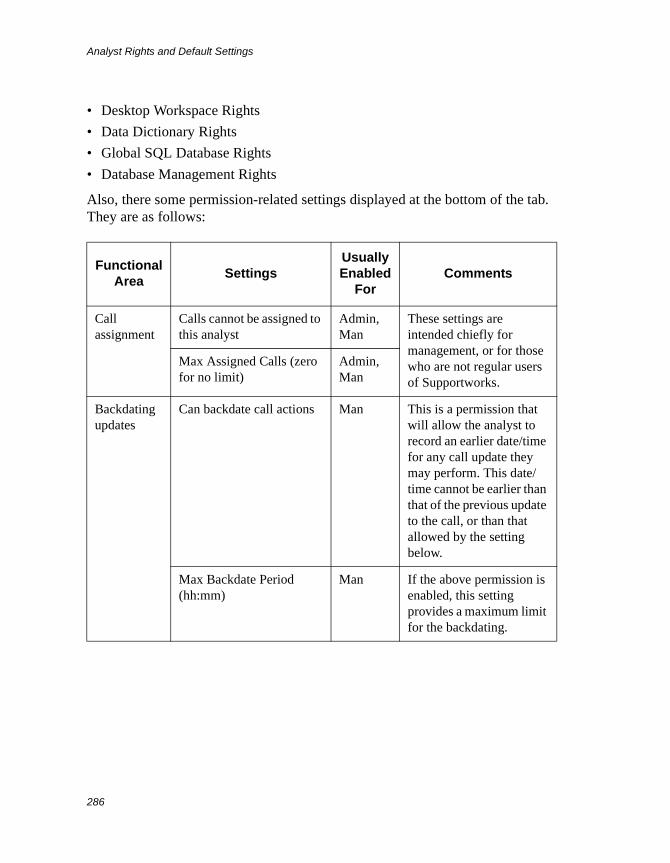
Analyst Rights and Default Settings
286
• Desktop Workspace Rights
• Data Dictionary Rights
• Global SQL Database Rights
• Database Management Rights
Also, there some permission-related settings displayed at the bottom of the tab. They are as follows:
Functional Area
SettingsUsually Enabled
ForComments
Call assignment
Calls cannot be assigned to this analyst
Admin, Man
These settings are intended chiefly for management, or for those who are not regular users of Supportworks.
Max Assigned Calls (zero for no limit)
Admin, Man
Backdating updates
Can backdate call actions Man This is a permission that will allow the analyst to record an earlier date/time for any call update they may perform. This date/time cannot be earlier than that of the previous update to the call, or than that allowed by the setting below.
Max Backdate Period (hh:mm)
Man If the above permission is enabled, this setting provides a maximum limit for the backdating.
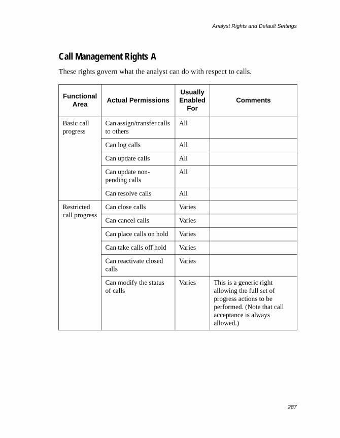
Analyst Rights and Default Settings
287
Call Management Rights A
These rights govern what the analyst can do with respect to calls.
Functional Area
Actual PermissionsUsually Enabled
ForComments
Basic call progress
Can assign/transfer calls to others
All
Can log calls All
Can update calls All
Can update non-pending calls
All
Can resolve calls All
Restricted call progress
Can close calls Varies
Can cancel calls Varies
Can place calls on hold Varies
Can take calls off hold Varies
Can reactivate closed calls
Varies
Can modify the status of calls
Varies This is a generic right allowing the full set of progress actions to be performed. (Note that call acceptance is always allowed.)
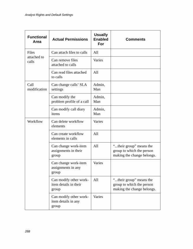
Analyst Rights and Default Settings
288
Files attached to calls
Can attach files to calls All
Can remove files attached to calls
Varies
Can read files attached to calls
All
Call modification
Can change calls’ SLA settings
Admin, Man
Can modify the problem profile of a call
Admin, Man
Can modify call diary items
Admin, Man
Workflow Can delete workflow elements
Varies
Can create workflow elements in calls
All
Can change work-item assignments in their group
All “...their group” means the group to which the person making the change belongs.
Can change work-item assignments in any group
Varies
Can modify other work-item details in their group
All “...their group” means the group to which the person making the change belongs.
Can modify other work-item details in any group
Varies
Functional Area
Actual PermissionsUsually Enabled
ForComments
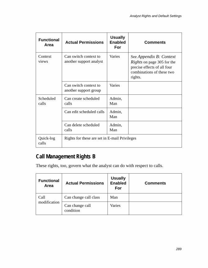
Analyst Rights and Default Settings
289
Call Management Rights B
These rights, too, govern what the analyst can do with respect to calls.
Context views
Can switch context to another support analyst
Varies See Appendix B: Context Rights on page 305 for the precise effects of all four combinations of these two rights.
Can switch context to another support group
Varies
Scheduled calls
Can create scheduled calls
Admin, Man
Can edit scheduled calls Admin, Man
Can delete scheduled calls
Admin, Man
Quick-log calls
Rights for these are set in E-mail Privileges
Functional Area
Actual PermissionsUsually Enabled
ForComments
Call modification
Can change call class Man
Can change call condition
Varies
Functional Area
Actual PermissionsUsually Enabled
ForComments
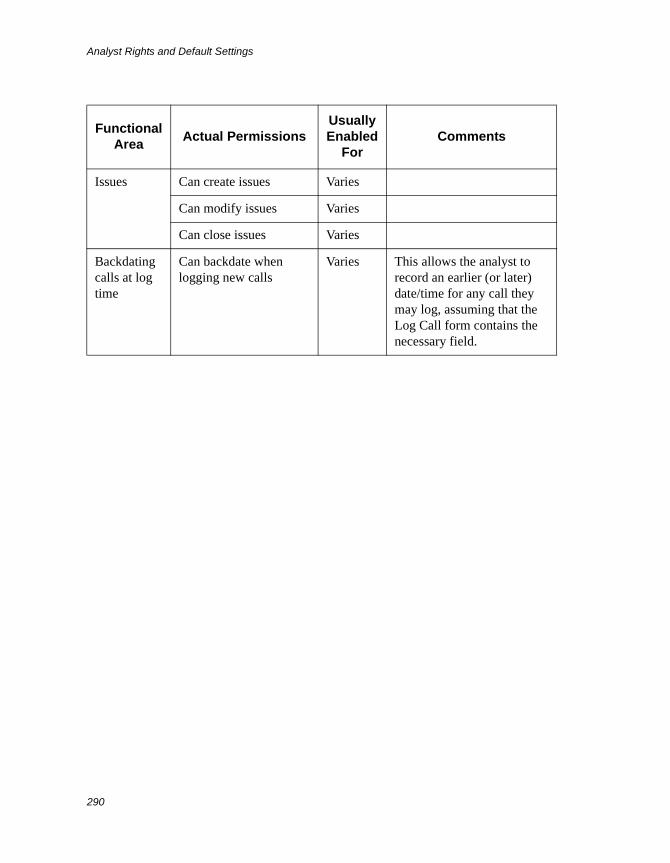
Analyst Rights and Default Settings
290
Issues Can create issues Varies
Can modify issues Varies
Can close issues Varies
Backdating calls at log time
Can backdate when logging new calls
Varies This allows the analyst to record an earlier (or later) date/time for any call they may log, assuming that the Log Call form contains the necessary field.
Functional Area
Actual PermissionsUsually Enabled
ForComments
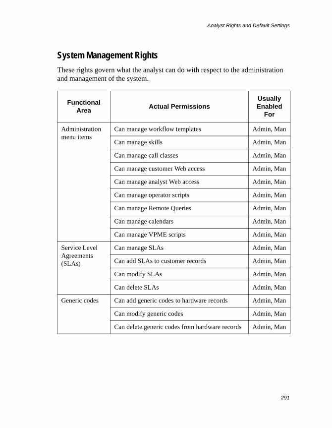
Analyst Rights and Default Settings
291
System Management Rights
These rights govern what the analyst can do with respect to the administration and management of the system.
Functional Area
Actual PermissionsUsually Enabled
For
Administration menu items
Can manage workflow templates Admin, Man
Can manage skills Admin, Man
Can manage call classes Admin, Man
Can manage customer Web access Admin, Man
Can manage analyst Web access Admin, Man
Can manage operator scripts Admin, Man
Can manage Remote Queries Admin, Man
Can manage calendars Admin, Man
Can manage VPME scripts Admin, Man
Service Level Agreements (SLAs)
Can manage SLAs Admin, Man
Can add SLAs to customer records Admin, Man
Can modify SLAs Admin, Man
Can delete SLAs Admin, Man
Generic codes Can add generic codes to hardware records Admin, Man
Can modify generic codes Admin, Man
Can delete generic codes from hardware records Admin, Man
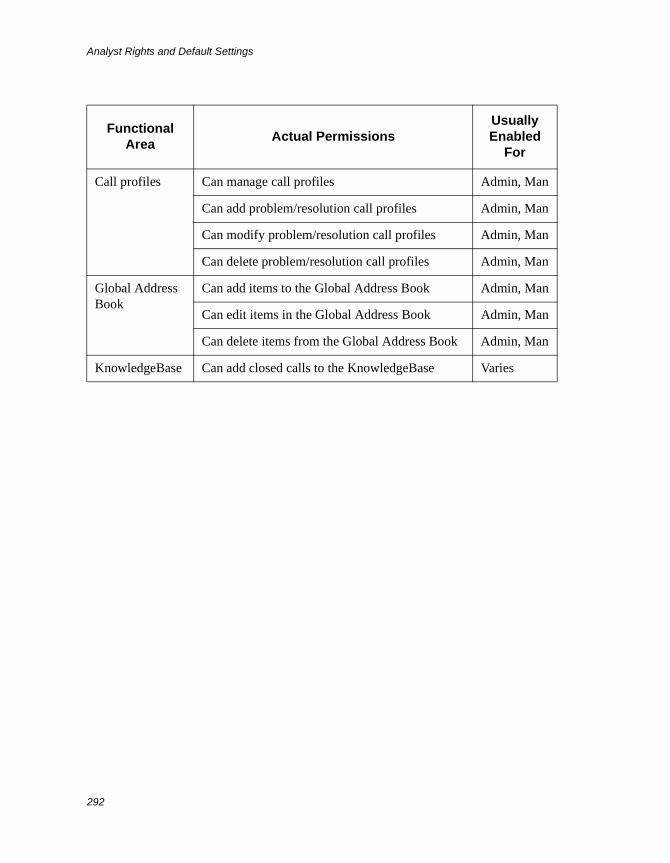
Analyst Rights and Default Settings
292
Call profiles Can manage call profiles Admin, Man
Can add problem/resolution call profiles Admin, Man
Can modify problem/resolution call profiles Admin, Man
Can delete problem/resolution call profiles Admin, Man
Global Address Book
Can add items to the Global Address Book Admin, Man
Can edit items in the Global Address Book Admin, Man
Can delete items from the Global Address Book Admin, Man
KnowledgeBase Can add closed calls to the KnowledgeBase Varies
Functional Area
Actual PermissionsUsually Enabled
For
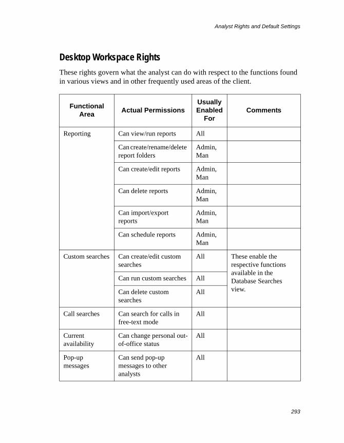
Analyst Rights and Default Settings
293
Desktop Workspace Rights
These rights govern what the analyst can do with respect to the functions found in various views and in other frequently used areas of the client.
Functional Area
Actual PermissionsUsually Enabled
ForComments
Reporting Can view/run reports All
Can create/rename/delete report folders
Admin, Man
Can create/edit reports Admin, Man
Can delete reports Admin, Man
Can import/export reports
Admin, Man
Can schedule reports Admin, Man
Custom searches Can create/edit custom searches
All These enable the respective functions available in the Database Searches view.
Can run custom searches All
Can delete custom searches
All
Call searches Can search for calls in free-text mode
All
Current availability
Can change personal out-of-office status
All
Pop-up messages
Can send pop-up messages to other analysts
All
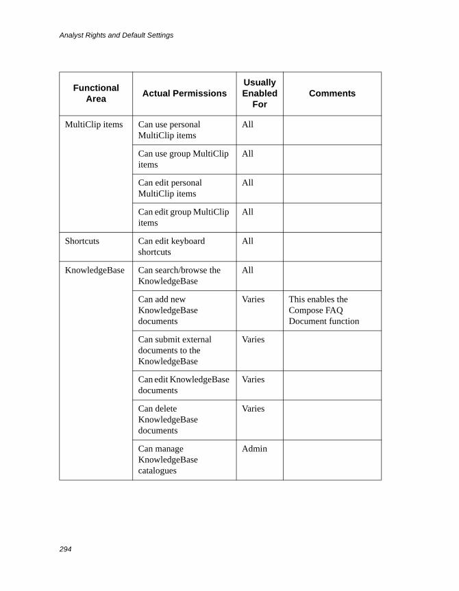
Analyst Rights and Default Settings
294
MultiClip items Can use personal MultiClip items
All
Can use group MultiClip items
All
Can edit personal MultiClip items
All
Can edit group MultiClip items
All
Shortcuts Can edit keyboard shortcuts
All
KnowledgeBase Can search/browse the KnowledgeBase
All
Can add new KnowledgeBase documents
Varies This enables the Compose FAQ Document function
Can submit external documents to the KnowledgeBase
Varies
Can edit KnowledgeBase documents
Varies
Can delete KnowledgeBase documents
Varies
Can manage KnowledgeBase catalogues
Admin
Functional Area
Actual PermissionsUsually Enabled
ForComments
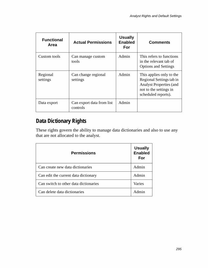
Analyst Rights and Default Settings
295
Data Dictionary Rights
These rights govern the ability to manage data dictionaries and also to use any that are not allocated to the analyst.
Custom tools Can manage custom tools
Admin This refers to functions in the relevant tab of Options and Settings
Regional settings
Can change regional settings
Admin This applies only to the Regional Settings tab in Analyst Properties (and not to the settings in scheduled reports).
Data export Can export data from list controls
Admin
PermissionsUsually Enabled
For
Can create new data dictionaries Admin
Can edit the current data dictionary Admin
Can switch to other data dictionaries Varies
Can delete data dictionaries Admin
Functional Area
Actual PermissionsUsually Enabled
ForComments
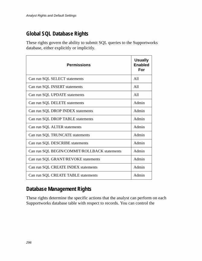
Analyst Rights and Default Settings
296
Global SQL Database Rights
These rights govern the ability to submit SQL queries to the Supportworks database, either explicitly or implicitly.
Database Management Rights
These rights determine the specific actions that the analyst can perform on each Supportworks database table with respect to records. You can control the
PermissionsUsually Enabled
For
Can run SQL SELECT statements All
Can run SQL INSERT statements All
Can run SQL UPDATE statements All
Can run SQL DELETE statements Admin
Can run SQL DROP INDEX statements Admin
Can run SQL DROP TABLE statements Admin
Can run SQL ALTER statements Admin
Can run SQL TRUNCATE statements Admin
Can run SQL DESCRIBE statements Admin
Can run SQL BEGIN/COMMIT/ROLLBACK statements Admin
Can run SQL GRANT/REVOKE statements Admin
Can run SQL CREATE INDEX statements Admin
Can run SQL CREATE TABLE statements Admin
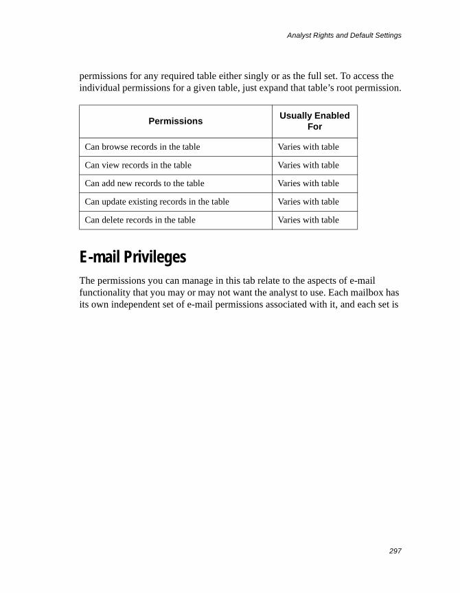
Analyst Rights and Default Settings
297
permissions for any required table either singly or as the full set. To access the individual permissions for a given table, just expand that table’s root permission.
E-mail PrivilegesThe permissions you can manage in this tab relate to the aspects of e-mail functionality that you may or may not want the analyst to use. Each mailbox has its own independent set of e-mail permissions associated with it, and each set is
PermissionsUsually Enabled
For
Can browse records in the table Varies with table
Can view records in the table Varies with table
Can add new records to the table Varies with table
Can update existing records in the table Varies with table
Can delete records in the table Varies with table
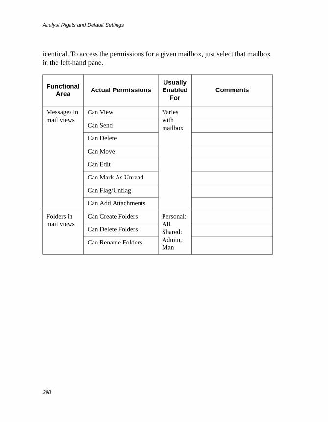
Analyst Rights and Default Settings
298
identical. To access the permissions for a given mailbox, just select that mailbox in the left-hand pane.
Functional Area
Actual PermissionsUsually Enabled
ForComments
Messages in mail views
Can View Varies with mailboxCan Send
Can Delete
Can Move
Can Edit
Can Mark As Unread
Can Flag/Unflag
Can Add Attachments
Folders in mail views
Can Create Folders Personal: AllShared: Admin, Man
Can Delete Folders
Can Rename Folders
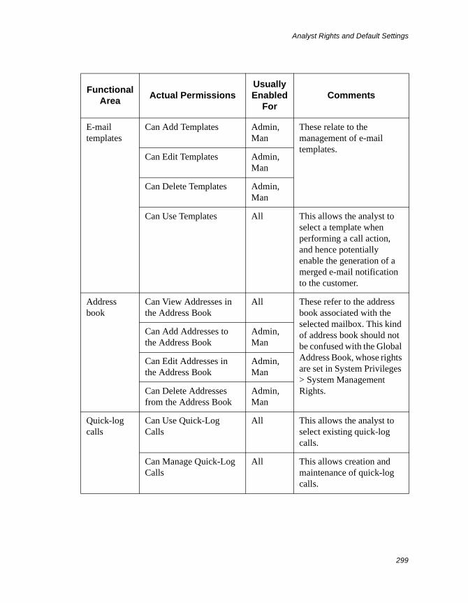
Analyst Rights and Default Settings
299
E-mail templates
Can Add Templates Admin, Man
These relate to the management of e-mail templates.
Can Edit Templates Admin, Man
Can Delete Templates Admin, Man
Can Use Templates All This allows the analyst to select a template when performing a call action, and hence potentially enable the generation of a merged e-mail notification to the customer.
Address book
Can View Addresses in the Address Book
All These refer to the address book associated with the selected mailbox. This kind of address book should not be confused with the Global Address Book, whose rights are set in System Privileges > System Management Rights.
Can Add Addresses to the Address Book
Admin, Man
Can Edit Addresses in the Address Book
Admin, Man
Can Delete Addresses from the Address Book
Admin, Man
Quick-log calls
Can Use Quick-Log Calls
All This allows the analyst to select existing quick-log calls.
Can Manage Quick-Log Calls
All This allows creation and maintenance of quick-log calls.
Functional Area
Actual PermissionsUsually Enabled
ForComments
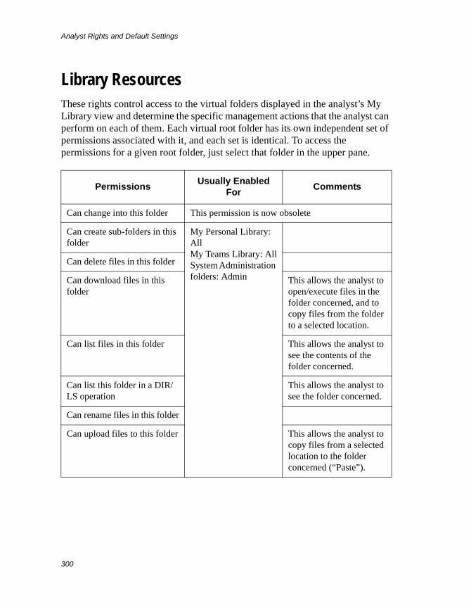
Analyst Rights and Default Settings
300
Library ResourcesThese rights control access to the virtual folders displayed in the analyst’s My Library view and determine the specific management actions that the analyst can perform on each of them. Each virtual root folder has its own independent set of permissions associated with it, and each set is identical. To access the permissions for a given root folder, just select that folder in the upper pane.
PermissionsUsually Enabled
ForComments
Can change into this folder This permission is now obsolete
Can create sub-folders in this folder
My Personal Library: AllMy Teams Library: AllSystem Administration folders: Admin
Can delete files in this folder
Can download files in this folder
This allows the analyst to open/execute files in the folder concerned, and to copy files from the folder to a selected location.
Can list files in this folder This allows the analyst to see the contents of the folder concerned.
Can list this folder in a DIR/LS operation
This allows the analyst to see the folder concerned.
Can rename files in this folder
Can upload files to this folder This allows the analyst to copy files from a selected location to the folder concerned (“Paste”).
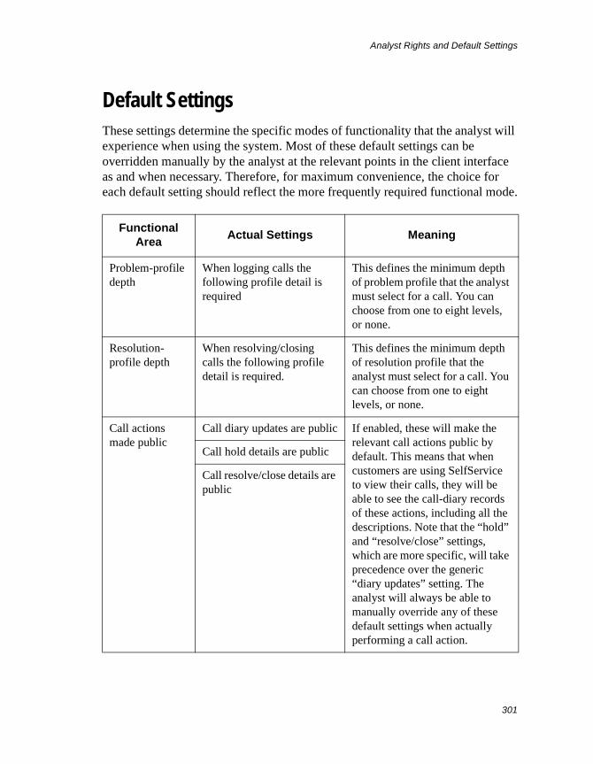
Analyst Rights and Default Settings
301
Default SettingsThese settings determine the specific modes of functionality that the analyst will experience when using the system. Most of these default settings can be overridden manually by the analyst at the relevant points in the client interface as and when necessary. Therefore, for maximum convenience, the choice for each default setting should reflect the more frequently required functional mode.
Functional Area
Actual Settings Meaning
Problem-profile depth
When logging calls the following profile detail is required
This defines the minimum depth of problem profile that the analyst must select for a call. You can choose from one to eight levels, or none.
Resolution-profile depth
When resolving/closing calls the following profile detail is required.
This defines the minimum depth of resolution profile that the analyst must select for a call. You can choose from one to eight levels, or none.
Call actions made public
Call diary updates are public If enabled, these will make the relevant call actions public by default. This means that when customers are using SelfService to view their calls, they will be able to see the call-diary records of these actions, including all the descriptions. Note that the “hold” and “resolve/close” settings, which are more specific, will take precedence over the generic “diary updates” setting. The analyst will always be able to manually override any of these default settings when actually performing a call action.
Call hold details are public
Call resolve/close details are public
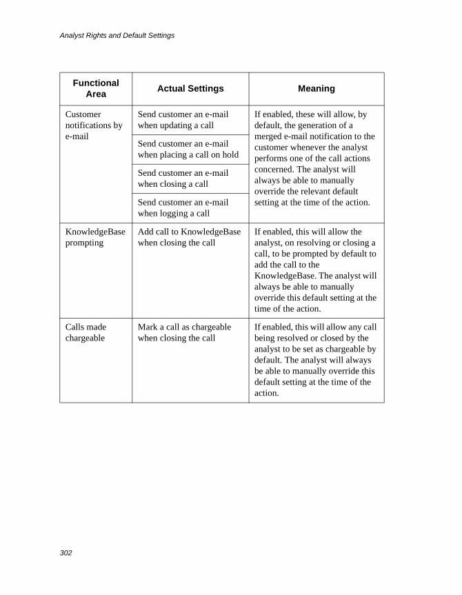
Analyst Rights and Default Settings
302
Customer notifications by e-mail
Send customer an e-mail when updating a call
If enabled, these will allow, by default, the generation of a merged e-mail notification to the customer whenever the analyst performs one of the call actions concerned. The analyst will always be able to manually override the relevant default setting at the time of the action.
Send customer an e-mail when placing a call on hold
Send customer an e-mail when closing a call
Send customer an e-mail when logging a call
KnowledgeBase prompting
Add call to KnowledgeBase when closing the call
If enabled, this will allow the analyst, on resolving or closing a call, to be prompted by default to add the call to the KnowledgeBase. The analyst will always be able to manually override this default setting at the time of the action.
Calls made chargeable
Mark a call as chargeable when closing the call
If enabled, this will allow any call being resolved or closed by the analyst to be set as chargeable by default. The analyst will always be able to manually override this default setting at the time of the action.
Functional Area
Actual Settings Meaning
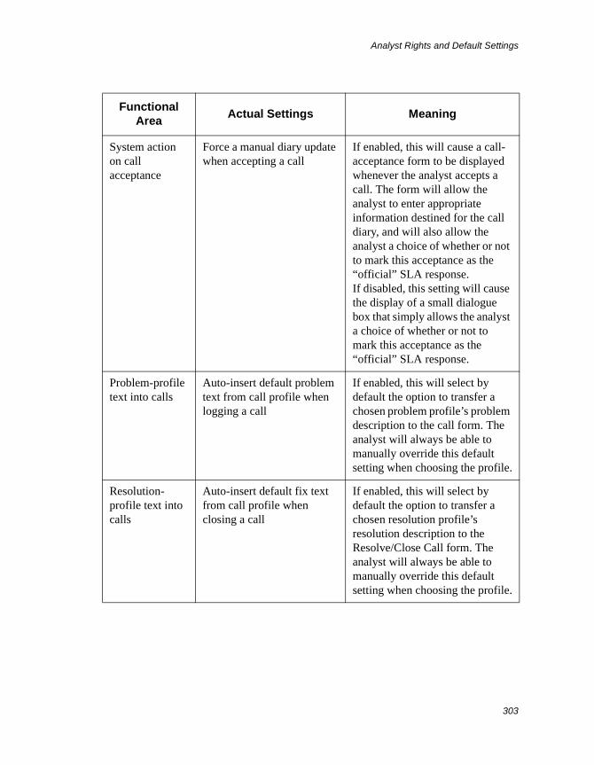
Analyst Rights and Default Settings
303
System action on call acceptance
Force a manual diary update when accepting a call
If enabled, this will cause a call-acceptance form to be displayed whenever the analyst accepts a call. The form will allow the analyst to enter appropriate information destined for the call diary, and will also allow the analyst a choice of whether or not to mark this acceptance as the “official” SLA response.If disabled, this setting will cause the display of a small dialogue box that simply allows the analyst a choice of whether or not to mark this acceptance as the “official” SLA response.
Problem-profile text into calls
Auto-insert default problem text from call profile when logging a call
If enabled, this will select by default the option to transfer a chosen problem profile’s problem description to the call form. The analyst will always be able to manually override this default setting when choosing the profile.
Resolution-profile text into calls
Auto-insert default fix text from call profile when closing a call
If enabled, this will select by default the option to transfer a chosen resolution profile’s resolution description to the Resolve/Close Call form. The analyst will always be able to manually override this default setting when choosing the profile.
Functional Area
Actual Settings Meaning
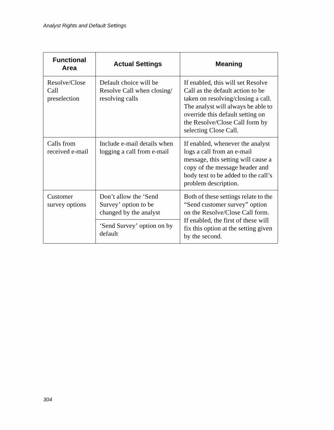
Analyst Rights and Default Settings
304
Resolve/Close Call preselection
Default choice will be Resolve Call when closing/resolving calls
If enabled, this will set Resolve Call as the default action to be taken on resolving/closing a call. The analyst will always be able to override this default setting on the Resolve/Close Call form by selecting Close Call.
Calls from received e-mail
Include e-mail details when logging a call from e-mail
If enabled, whenever the analyst logs a call from an e-mail message, this setting will cause a copy of the message header and body text to be added to the call’s problem description.
Customer survey options
Don’t allow the ‘Send Survey’ option to be changed by the analyst
Both of these settings relate to the “Send customer survey” option on the Resolve/Close Call form. If enabled, the first of these will fix this option at the setting given by the second.
‘Send Survey’ option on by default
Functional Area
Actual Settings Meaning
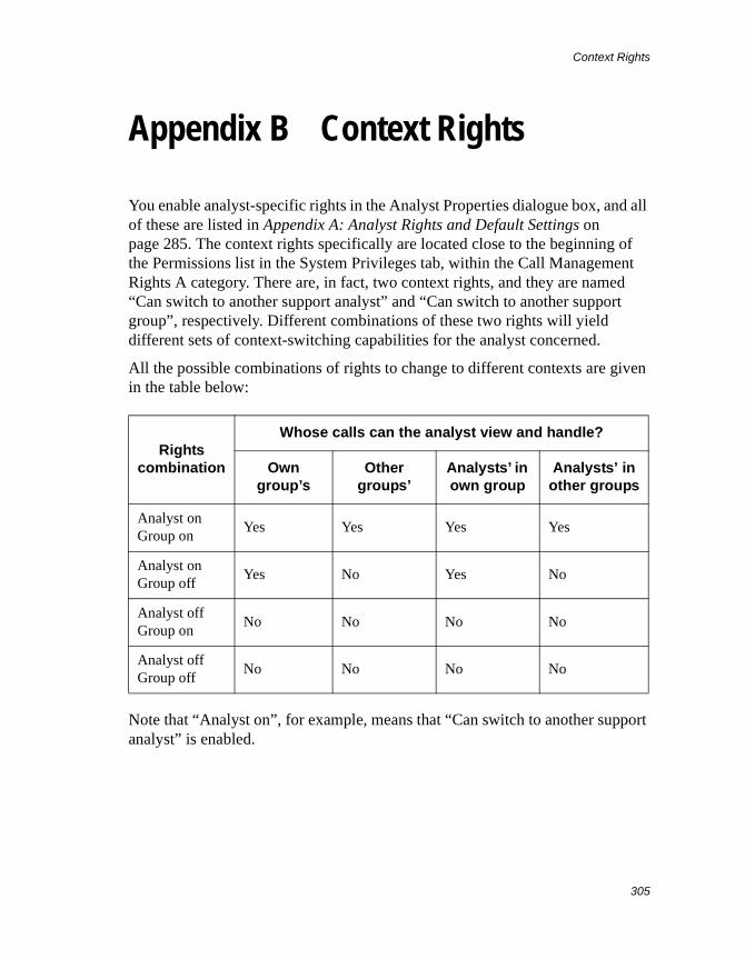
Context Rights
305
Appendix B Context Rights
You enable analyst-specific rights in the Analyst Properties dialogue box, and all of these are listed in Appendix A: Analyst Rights and Default Settings on page 285. The context rights specifically are located close to the beginning of the Permissions list in the System Privileges tab, within the Call Management Rights A category. There are, in fact, two context rights, and they are named “Can switch to another support analyst” and “Can switch to another support group”, respectively. Different combinations of these two rights will yield different sets of context-switching capabilities for the analyst concerned.
All the possible combinations of rights to change to different contexts are given in the table below:
Note that “Analyst on”, for example, means that “Can switch to another support analyst” is enabled.
Rights combination
Whose calls can the analyst view and handle?
Own group’s
Other groups’
Analysts’ in own group
Analysts’ in other groups
Analyst onGroup on
Yes Yes Yes Yes
Analyst onGroup off
Yes No Yes No
Analyst offGroup on
No No No No
Analyst offGroup off
No No No No

Context Rights
306
E-mail Template Variables
307
Appendix C E-mail Template Variables
The Supportworks customer-notification and Auto Responder e-mail templates can contain variables within the message text. These variables are replaced with the actual data they represent whenever a specific response message is generated. Most of the data would be derived from the relevant database tables, while the rest would be data generated on-the-fly by the system. The variables are, in fact, macro commands that execute the required substitution in each case.
A variable is recognisable by the fact that it starts with a dollar ($) symbol, and ends with an exclamation (!) symbol. Thus, a variable such as $Customer! may represent a customer name – for example, Fred Bloggs.
When editing a template, you can insert any of the allowed set of variables into it. You can either use the drop-down list (containing the user-friendly display names of the variables) and the Insert Variable button at the top, or you could type the names of the variables in the same way as text.
A useful property of the variable name is its ability to let you control the case of the text it represents, as displayed in the generated response. If the variable name is all upper case, then the actual output text will be all upper case. If the variable name is all lower case, then the actual text will be all lower case. If mixed case is used for the variable name, then the case of the output text will reflect that of the original text in the database table.
So, if you were to type the variable as $CUSTOMER!, that would appear as “FRED BLOGGS” in the mailed response. Conversely, if you typed the variable as $customer!, that would produce the text in the form “fred bloggs”. Finally, if you typed the variable as $Customer!, the text would be output as “Fred Bloggs”.
The tables in the following sections give you the meanings of all the variables that are available for use in each type of e-mail template. Although the variable names are shown here in the most appropriate case for each variable, they could equally be in any desired case.
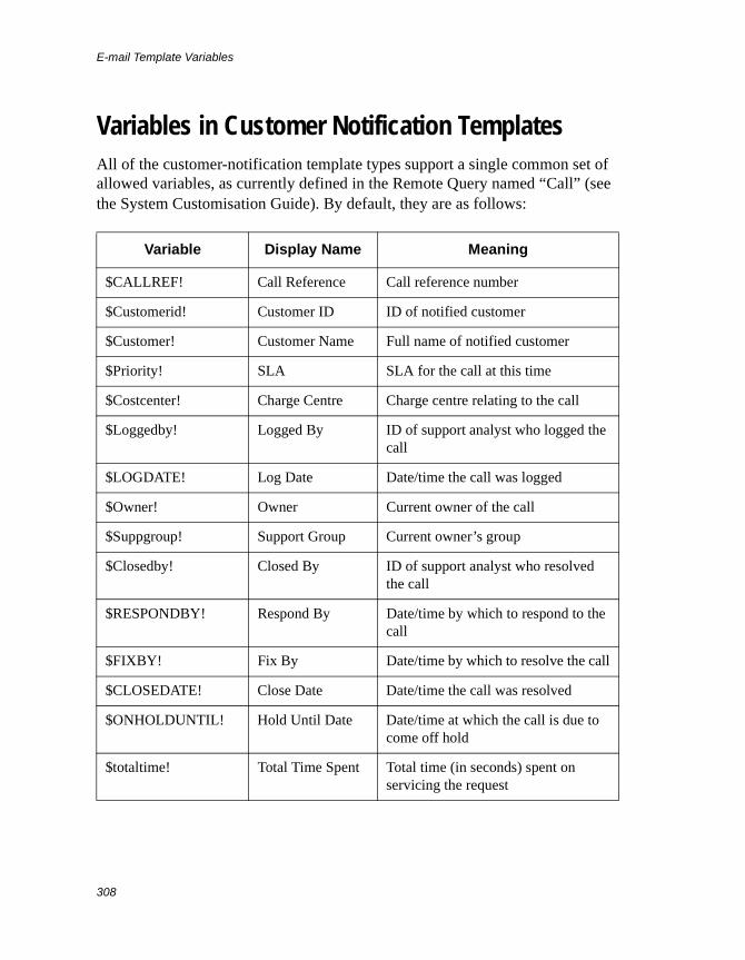
E-mail Template Variables
308
Variables in Customer Notification TemplatesAll of the customer-notification template types support a single common set of allowed variables, as currently defined in the Remote Query named “Call” (see the System Customisation Guide). By default, they are as follows:
Variable Display Name Meaning
$CALLREF! Call Reference Call reference number
$Customerid! Customer ID ID of notified customer
$Customer! Customer Name Full name of notified customer
$Priority! SLA SLA for the call at this time
$Costcenter! Charge Centre Charge centre relating to the call
$Loggedby! Logged By ID of support analyst who logged the call
$LOGDATE! Log Date Date/time the call was logged
$Owner! Owner Current owner of the call
$Suppgroup! Support Group Current owner’s group
$Closedby! Closed By ID of support analyst who resolved the call
$RESPONDBY! Respond By Date/time by which to respond to the call
$FIXBY! Fix By Date/time by which to resolve the call
$CLOSEDATE! Close Date Date/time the call was resolved
$ONHOLDUNTIL! Hold Until Date Date/time at which the call is due to come off hold
$totaltime! Total Time Spent Total time (in seconds) spent on servicing the request
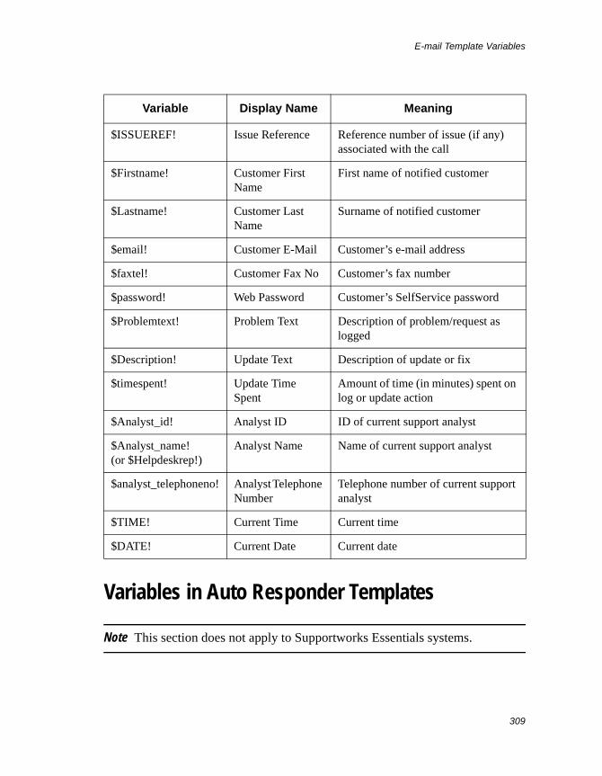
E-mail Template Variables
309
Variables in Auto Responder Templates
Note This section does not apply to Supportworks Essentials systems.
$ISSUEREF! Issue Reference Reference number of issue (if any) associated with the call
$Firstname! Customer First Name
First name of notified customer
$Lastname! Customer Last Name
Surname of notified customer
$email! Customer E-Mail Customer’s e-mail address
$faxtel! Customer Fax No Customer’s fax number
$password! Web Password Customer’s SelfService password
$Problemtext! Problem Text Description of problem/request as logged
$Description! Update Text Description of update or fix
$timespent! Update Time Spent
Amount of time (in minutes) spent on log or update action
$Analyst_id! Analyst ID ID of current support analyst
$Analyst_name!(or $Helpdeskrep!)
Analyst Name Name of current support analyst
$analyst_telephoneno! Analyst Telephone Number
Telephone number of current support analyst
$TIME! Current Time Current time
$DATE! Current Date Current date
Variable Display Name Meaning
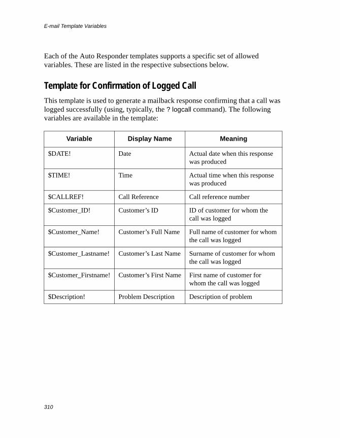
E-mail Template Variables
310
Each of the Auto Responder templates supports a specific set of allowed variables. These are listed in the respective subsections below.
Template for Confirmation of Logged Call
This template is used to generate a mailback response confirming that a call was logged successfully (using, typically, the ? logcall command). The following variables are available in the template:
Variable Display Name Meaning
$DATE! Date Actual date when this response was produced
$TIME! Time Actual time when this response was produced
$CALLREF! Call Reference Call reference number
$Customer_ID! Customer’s ID ID of customer for whom the call was logged
$Customer_Name! Customer’s Full Name Full name of customer for whom the call was logged
$Customer_Lastname! Customer’s Last Name Surname of customer for whom the call was logged
$Customer_Firstname! Customer’s First Name First name of customer for whom the call was logged
$Description! Problem Description Description of problem
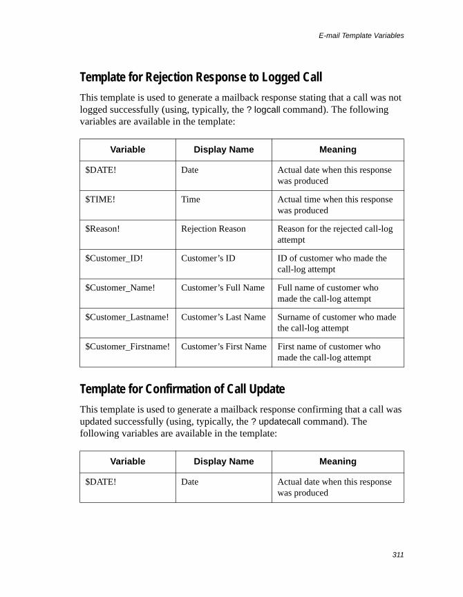
E-mail Template Variables
311
Template for Rejection Response to Logged Call
This template is used to generate a mailback response stating that a call was not logged successfully (using, typically, the ? logcall command). The following variables are available in the template:
Template for Confirmation of Call Update
This template is used to generate a mailback response confirming that a call was updated successfully (using, typically, the ? updatecall command). The following variables are available in the template:
Variable Display Name Meaning
$DATE! Date Actual date when this response was produced
$TIME! Time Actual time when this response was produced
$Reason! Rejection Reason Reason for the rejected call-log attempt
$Customer_ID! Customer’s ID ID of customer who made the call-log attempt
$Customer_Name! Customer’s Full Name Full name of customer who made the call-log attempt
$Customer_Lastname! Customer’s Last Name Surname of customer who made the call-log attempt
$Customer_Firstname! Customer’s First Name First name of customer who made the call-log attempt
Variable Display Name Meaning
$DATE! Date Actual date when this response was produced
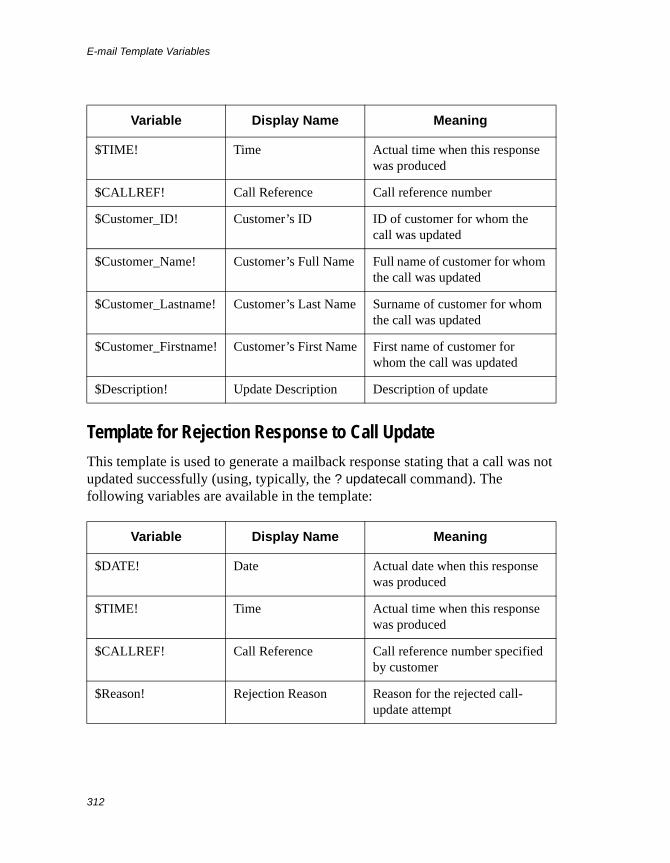
E-mail Template Variables
312
Template for Rejection Response to Call Update
This template is used to generate a mailback response stating that a call was not updated successfully (using, typically, the ? updatecall command). The following variables are available in the template:
$TIME! Time Actual time when this response was produced
$CALLREF! Call Reference Call reference number
$Customer_ID! Customer’s ID ID of customer for whom the call was updated
$Customer_Name! Customer’s Full Name Full name of customer for whom the call was updated
$Customer_Lastname! Customer’s Last Name Surname of customer for whom the call was updated
$Customer_Firstname! Customer’s First Name First name of customer for whom the call was updated
$Description! Update Description Description of update
Variable Display Name Meaning
$DATE! Date Actual date when this response was produced
$TIME! Time Actual time when this response was produced
$CALLREF! Call Reference Call reference number specified by customer
$Reason! Rejection Reason Reason for the rejected call-update attempt
Variable Display Name Meaning
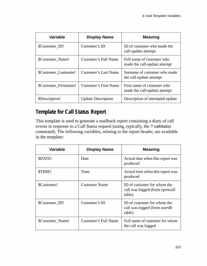
E-mail Template Variables
313
Template for Call Status Report
This template is used to generate a mailback report containing a diary of call events in response to a Call Status request (using, typically, the ? callstatus command). The following variables, relating to the report header, are available in the template:
$Customer_ID! Customer’s ID ID of customer who made the call-update attempt
$Customer_Name! Customer’s Full Name Full name of customer who made the call-update attempt
$Customer_Lastname! Customer’s Last Name Surname of customer who made the call-update attempt
$Customer_Firstname! Customer’s First Name First name of customer who made the call-update attempt
$Description! Update Description Description of attempted update
Variable Display Name Meaning
$DATE! Date Actual date when this report was produced
$TIME! Time Actual time when this report was produced
$Customer! Customer Name ID of customer for whom the call was logged (from opencall table)
$Customer_ID! Customer’s ID ID of customer for whom the call was logged (from userdb table)
$Customer_Name! Customer’s Full Name Full name of customer for whom the call was logged
Variable Display Name Meaning
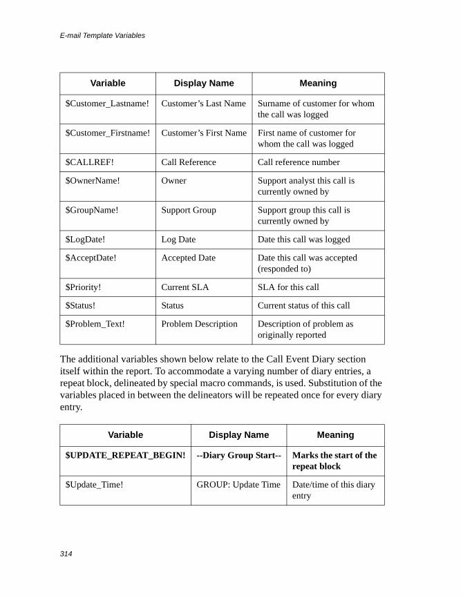
E-mail Template Variables
314
The additional variables shown below relate to the Call Event Diary section itself within the report. To accommodate a varying number of diary entries, a repeat block, delineated by special macro commands, is used. Substitution of the variables placed in between the delineators will be repeated once for every diary entry.
$Customer_Lastname! Customer’s Last Name Surname of customer for whom the call was logged
$Customer_Firstname! Customer’s First Name First name of customer for whom the call was logged
$CALLREF! Call Reference Call reference number
$OwnerName! Owner Support analyst this call is currently owned by
$GroupName! Support Group Support group this call is currently owned by
$LogDate! Log Date Date this call was logged
$AcceptDate! Accepted Date Date this call was accepted (responded to)
$Priority! Current SLA SLA for this call
$Status! Status Current status of this call
$Problem_Text! Problem Description Description of problem as originally reported
Variable Display Name Meaning
$UPDATE_REPEAT_BEGIN! --Diary Group Start-- Marks the start of the repeat block
$Update_Time! GROUP: Update Time Date/time of this diary entry
Variable Display Name Meaning
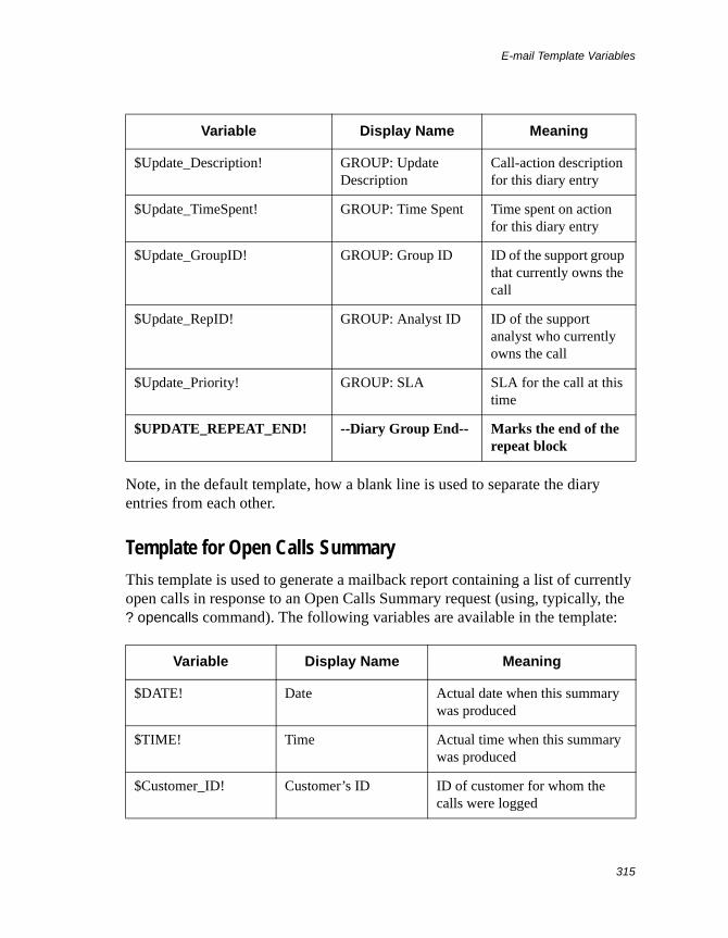
E-mail Template Variables
315
Note, in the default template, how a blank line is used to separate the diary entries from each other.
Template for Open Calls Summary
This template is used to generate a mailback report containing a list of currently open calls in response to an Open Calls Summary request (using, typically, the ? opencalls command). The following variables are available in the template:
$Update_Description! GROUP: Update Description
Call-action description for this diary entry
$Update_TimeSpent! GROUP: Time Spent Time spent on action for this diary entry
$Update_GroupID! GROUP: Group ID ID of the support group that currently owns the call
$Update_RepID! GROUP: Analyst ID ID of the support analyst who currently owns the call
$Update_Priority! GROUP: SLA SLA for the call at this time
$UPDATE_REPEAT_END! --Diary Group End-- Marks the end of the repeat block
Variable Display Name Meaning
$DATE! Date Actual date when this summary was produced
$TIME! Time Actual time when this summary was produced
$Customer_ID! Customer’s ID ID of customer for whom the calls were logged
Variable Display Name Meaning
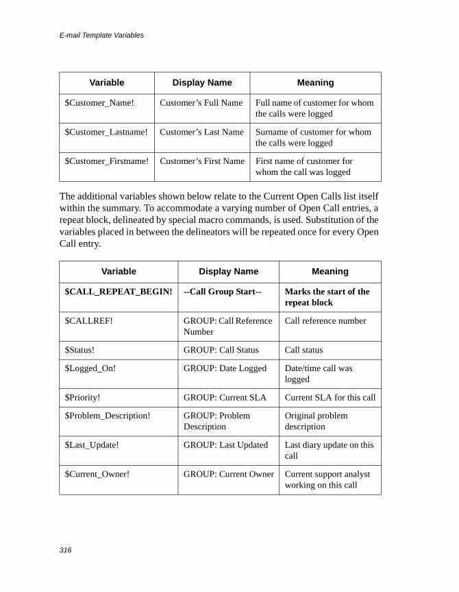
E-mail Template Variables
316
The additional variables shown below relate to the Current Open Calls list itself within the summary. To accommodate a varying number of Open Call entries, a repeat block, delineated by special macro commands, is used. Substitution of the variables placed in between the delineators will be repeated once for every Open Call entry.
$Customer_Name! Customer’s Full Name Full name of customer for whom the calls were logged
$Customer_Lastname! Customer’s Last Name Surname of customer for whom the calls were logged
$Customer_Firstname! Customer’s First Name First name of customer for whom the call was logged
Variable Display Name Meaning
$CALL_REPEAT_BEGIN! --Call Group Start-- Marks the start of the repeat block
$CALLREF! GROUP: Call Reference Number
Call reference number
$Status! GROUP: Call Status Call status
$Logged_On! GROUP: Date Logged Date/time call was logged
$Priority! GROUP: Current SLA Current SLA for this call
$Problem_Description! GROUP: Problem Description
Original problem description
$Last_Update! GROUP: Last Updated Last diary update on this call
$Current_Owner! GROUP: Current Owner Current support analyst working on this call
Variable Display Name Meaning
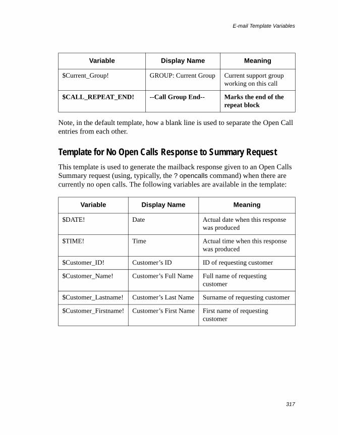
E-mail Template Variables
317
Note, in the default template, how a blank line is used to separate the Open Call entries from each other.
Template for No Open Calls Response to Summary Request
This template is used to generate the mailback response given to an Open Calls Summary request (using, typically, the ? opencalls command) when there are currently no open calls. The following variables are available in the template:
$Current_Group! GROUP: Current Group Current support group working on this call
$CALL_REPEAT_END! --Call Group End-- Marks the end of the repeat block
Variable Display Name Meaning
$DATE! Date Actual date when this response was produced
$TIME! Time Actual time when this response was produced
$Customer_ID! Customer’s ID ID of requesting customer
$Customer_Name! Customer’s Full Name Full name of requesting customer
$Customer_Lastname! Customer’s Last Name Surname of requesting customer
$Customer_Firstname! Customer’s First Name First name of requesting customer
Variable Display Name Meaning
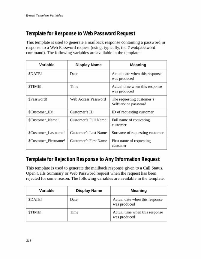
E-mail Template Variables
318
Template for Response to Web Password Request
This template is used to generate a mailback response containing a password in response to a Web Password request (using, typically, the ? webpassword command). The following variables are available in the template:
Template for Rejection Response to Any Information Request
This template is used to generate the mailback response given to a Call Status, Open Calls Summary or Web Password request when the request has been rejected for some reason. The following variables are available in the template:
Variable Display Name Meaning
$DATE! Date Actual date when this response was produced
$TIME! Time Actual time when this response was produced
$Password! Web Access Password The requesting customer’s SelfService password
$Customer_ID! Customer’s ID ID of requesting customer
$Customer_Name! Customer’s Full Name Full name of requesting customer
$Customer_Lastname! Customer’s Last Name Surname of requesting customer
$Customer_Firstname! Customer’s First Name First name of requesting customer
Variable Display Name Meaning
$DATE! Date Actual date when this response was produced
$TIME! Time Actual time when this response was produced
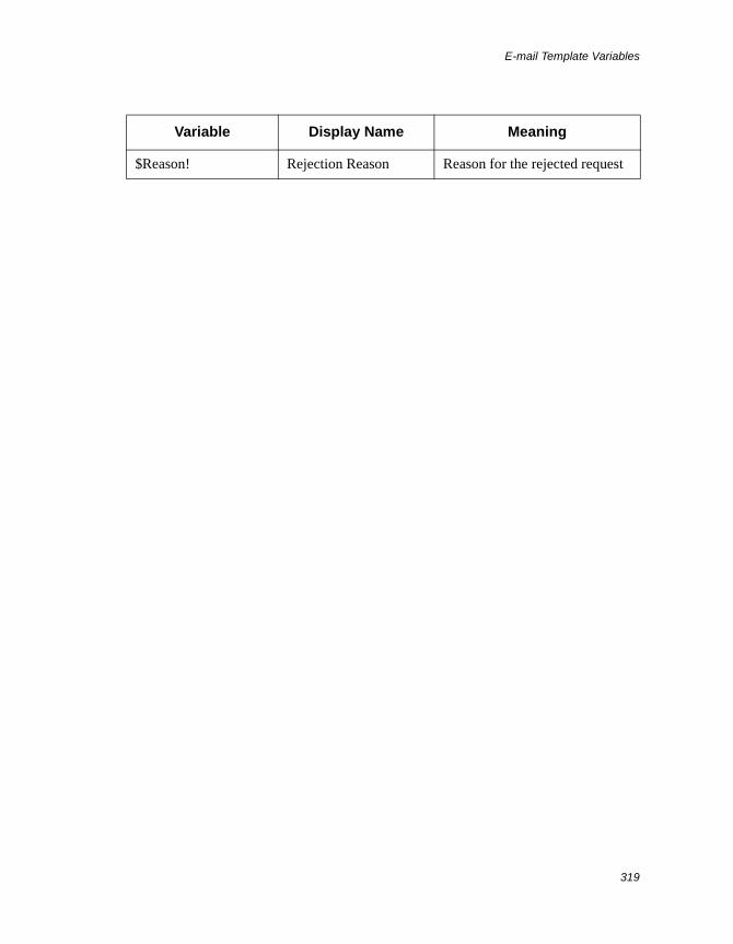
E-mail Template Variables
319
$Reason! Rejection Reason Reason for the rejected request
Variable Display Name Meaning

E-mail Template Variables
320
CTI Functionality and Number Specification
321
Appendix D CTI Functionality and Number Specification
Computer Telephony Integration (CTI), as incorporated into Supportworks, allows analysts to manage telephone communications with various parties associated with the team’s support function. These parties might include customers, manufacturers and/or suppliers. An incoming telephone call to an analyst’s CTI handset would be able to trigger a Customer-database look-up resulting in the caller’s details being displayed in the CTI Monitor window. The analyst could then initiate the logging of a call from that window. Supportworks CTI also allows an analyst to dial out to a party whose contact details are being displayed on a form or on an active page, assuming that a suitable button has been designed into that form or a suitable link has been created on that page.
Configuration (which includes enabling) of CTI is done from the Supportworks client and is applied on a per-workstation basis. See the chapter covering client-based configuration in the User Guide for details.
Telephone Number Entry on a FormWhen creating a customer record, the number you enter in the telephone-number field of the entry form will allow the system to pinpoint this customer’s record from the information contained in incoming telephone calls. When an analyst displays the customer’s record (on a form or on an active page), it is the same telephone number that will be dialled when the analyst clicks the appropriate button or link. Note that, although you are free to specify telephone numbers in manufacturer and supplier records for dial-out purposes, only the Customer table will be searched for a matching number on an incoming telephone call.
If, for a given customer, you can rely on a specific Calling Line Identifier (CLI) being submitted every time they call your helpdesk on the phone, the number to enter in the telephone-number field would be the CLI. On the other hand, if a customer has been given a unique number for calling the helpdesk that only they can use, then this would be submitted as the Called ID (or Station ID) in each of

CTI Functionality and Number Specification
322
their calls, and would therefore be the number to enter in the field. In the latter case, although the submitted Called ID would certainly identify the customer, it is obvious that the number could not be regarded as contact details, or be used to auto-dial the customer. In such instances, two separate telephone-number fields would be available for completion on the form, one whose contents would match the Called ID, and the other whose contents would be a suitable dial-out number.
When entering a telephone number in a form field, you can use any customary punctuation and spacing. If the helpdesk team is spread across different countries, you are strongly advised to use the full international format, which is as follows:
+<country code><space><number>
It is important to note that a space is required after the country code. Please also note that outgoing local or national calls will always be correctly dialled (and charged at the correct rate) even though you have specified an international number.
How SelfService Works
323
Appendix E How SelfService Works
The SelfService application has been implemented as one or more PHP-based services, each consisting of a set of PHP script files executed by the supplied script interpreter. Containing a mixture of PHP, HTML and JavaScript code, each script file generates a specific SelfService page as seen by your customers. Each set of these script files is held in a specific sub-folder whose location would typically be C:\Program Files \Hornbill \Supportworks Server \html \_selfservice. The sub-folder would have the same name as the service instance concerned. You will also see a sub-folder called _template in that location; this contains the script-file templates on which the script files of the individual service instances can be based.
Note When you upgrade your application, and the SelfService pages have been redesigned in the new version, only the template files are overwritten. Your customised script files will be unaffected.
The editable text content on the SelfService pages is held in the database and is dynamically accessed at display time via variables in the script-file code. Such a scheme allows your Web pages to be easily customised from the client, with no knowledge of PHP, HTML or JavaScript being needed. Of course, if you are familiar with these languages, you could change the entire design and functionality of the pages as well (subject to Hornbill’s agreement).
Customers will be able to access SelfService via a suitable link from somewhere on your website, or by typing a URL on their browsers, as previously documented. This causes the SelfService login page to be generated and displayed. Then, following a successful login, the SelfService home page would appear. Subsequent pages would be generated and displayed in response to specific requests made by the customer from that page, or from those subsequent SelfService pages.
Whenever SelfService is required to generate one of its pages, the following sequence of events occurs:
How SelfService Works
324
(a) The browser initiates an HTTP session, either by submitting the SelfService URL, or (subsequently) by invoking SelfService via a relevant call-related request.
(b) The Web server passes the script file relating to the requested page to the PHP interpreter for execution. In the case of the login page, for instance, this file would be index.php.
(c) As the script runs, it executes the PHP code while sending the HTML components to the Web browser. Any call-related information and editable text referenced via variables in the code is taken from the database and incorporated in the HTML stream.
(d) The SelfService application ends the HTTP session, and is then ready to accept the next request.
