sw user guide template - telit · le922a6 software user guide 1vv0301247 r0 – 2016-06-29...
TRANSCRIPT

Reproduction forbidden without written authorization from Telit Wireless Solutions Co., Ltd..- All Rights Reserved. Page 1 of 142
LE922A6 SW User Guide
1VV0301247 r0 – 2016-06-29

LE922A6 Software User Guide 1VV0301247 r0 – 2016-06-29
Reproduction forbidden without written authorization from Telit Wireless Solutions Co., Ltd..- All Rights Reserved. Page 2 of 142
APPLICABILITY TABLE
PRODUCT
LE922A6-A1
LE922A6-E1
SW Version
24.00.201 24.00.221

LE922A6 Software User Guide 1VV0301247 r0 – 2016-06-29
Reproduction forbidden without written authorization from Telit Wireless Solutions Co., Ltd..- All Rights Reserved. Page 3 of 142
SPECIFICATIONS SUBJECT TO CHANGE WITHOUT NOTICE
Notice
While reasonable efforts have been made to assure the accuracy of this document, Telit
assumes no liability resulting from any inaccuracies or omissions in this document, or from
use of the information obtained herein. The information in this document has been carefully
checked and is believed to be entirely reliable. However, no responsibility is assumed for
inaccuracies or omissions. Telit reserves the right to make changes to any products described
herein and reserves the right to revise this document and to make changes from time to time
in content hereof with no obligation to notify any person of revisions or changes. Telit does
not assume any liability arising out of the application or use of any product, software, or
circuit described herein; neither does it convey license under its patent rights or the rights of
others.
It is possible that this publication may contain references to, or information about Telit
products (machines and programs), programming, or services that are not announced in your
country. Such references or information must not be construed to mean that Telit intends to
announce such Telit products, programming, or services in your country.
Copyrights
This instruction manual and the Telit products described in this instruction manual may be,
include or describe copyrighted Telit material, such as computer programs stored in
semiconductor memories or other media. Laws in the Italy and other countries preserve for
Telit and its licensors certain exclusive rights for copyrighted material, including the
exclusive right to copy, reproduce in any form, distribute and make derivative works of the
copyrighted material. Accordingly, any copyrighted material of Telit and its licensors
contained herein or in the Telit products described in this instruction manual may not be
copied, reproduced, distributed, merged or modified in any manner without the express
written permission of Telit. Furthermore, the purchase of Telit products shall not be deemed
to grant either directly or by implication, estoppel, or otherwise, any license under the
copyrights, patents or patent applications of Telit, as arises by operation of law in the sale of a
product.
Computer Software Copyrights
The Telit and 3rd Party supplied Software (SW) products described in this instruction manual
may include copyrighted Telit and other 3rd Party supplied computer programs stored in
semiconductor memories or other media. Laws in the Italy and other countries preserve for
Telit and other 3rd Party supplied SW certain exclusive rights for copyrighted computer
programs, including the exclusive right to copy or reproduce in any form the copyrighted
computer program. Accordingly, any copyrighted Telit or other 3rd Party supplied SW
computer programs contained in the Telit products described in this instruction manual may
not be copied (reverse engineered) or reproduced in any manner without the express written
permission of Telit or the 3rd Party SW supplier. Furthermore, the purchase of Telit products
shall not be deemed to grant either directly or by implication, estoppel, or otherwise, any
license under the copyrights, patents or patent applications of Telit or other 3rd Party supplied
SW, except for the normal non-exclusive, royalty free license to use that arises by operation
of law in the sale of a product.

LE922A6 Software User Guide 1VV0301247 r0 – 2016-06-29
Reproduction forbidden without written authorization from Telit Wireless Solutions Co., Ltd..- All Rights Reserved. Page 4 of 142
Usage and Disclosure Restrictions
License Agreements
The software described in this document is the property of Telit and its licensors. It is
furnished by express license agreement only and may be used only in accordance with the
terms of such an agreement.
Copyrighted Materials
Software and documentation are copyrighted materials. Making unauthorized copies is
prohibited by law. No part of the software or documentation may be reproduced, transmitted,
transcribed, stored in a retrieval system, or translated into any language or computer language,
in any form or by any means, without prior written permission of Telit
High Risk Materials
Components, units, or third-party products used in the product described herein are NOT
fault-tolerant and are NOT designed, manufactured, or intended for use as on-line control
equipment in the following hazardous environments requiring fail-safe controls: the operation
of Nuclear Facilities, Aircraft Navigation or Aircraft Communication Systems, Air Traffic
Control, Life Support, or Weapons Systems (High Risk Activities"). Telit and its supplier(s)
specifically disclaim any expressed or implied warranty of fitness for such High Risk
Activities.
Trademarks
TELIT and the Stylized T Logo are registered in Trademark Office. All other product or
service names are the property of their respective owners.
Copyright © Telit Wireless Solutions Co., Ltd.

LE922A6 Software User Guide 1VV0301247 r0 – 2016-06-29
Reproduction forbidden without written authorization from Telit Wireless Solutions Co., Ltd..- All Rights Reserved. Page 5 of 142
Contents
1. Introduction ................................................................................................................. 11
1.1. Scope ..................................................................................................................... 11
1.2. Audience ................................................................................................................ 11
1.3. Contact Information, Support ................................................................................. 11
1.4. Document Organization ......................................................................................... 11
1.5. Text Conventions ................................................................................................... 12
1.6. Related Documents ................................................................................................ 12
2. Overview ...................................................................................................................... 13
3. LE922A6 Product Specification ................................................................................. 14
4. Basic Operations ........................................................................................................ 15
4.1. Command Syntax ................................................................................................... 15
4.2. Command Response Timeout ................................................................................ 15
4.3. Turning ON/OFF the LE922A6 family .................................................................... 17
4.4. Checking Device Functionality ............................................................................... 17
4.4.1. Baudrate .................................................................................................................... 17
4.5. USB Configuration ................................................................................................. 17
4.5.1. USB interface............................................................................................................. 18
4.5.2. USB configuration setup ............................................................................................ 19
4.6. SIM/UICC ............................................................................................................... 19
4.6.1. SIM/UICC Presence and PIN Request ....................................................................... 19
4.6.2. Enter PIN code .......................................................................................................... 20
4.6.3. Enter PUK code ......................................................................................................... 20
4.6.4. SIM/UICC Status ....................................................................................................... 20
4.6.5. SIM/UICC Detection Mode ......................................................................................... 21
4.6.6. SIM/USIM access File ................................................................................................ 23
4.6.7. MSISDN ..................................................................................................................... 24
4.6.8. Preferred Operator List .............................................................................................. 25
4.7. Network Checking .................................................................................................. 27
4.7.1. Query Network Status ................................................................................................ 27
4.7.1.1. CS network registration status in UTRAN/E-UTRAN ........................................... 27
4.7.1.2. PS network registration status in UTRAN ............................................................ 27
4.7.1.3. PS network registration status in E-UTRAN ........................................................ 28
4.7.2. Network Operator Identification .................................................................................. 28

LE922A6 Software User Guide 1VV0301247 r0 – 2016-06-29
Reproduction forbidden without written authorization from Telit Wireless Solutions Co., Ltd..- All Rights Reserved. Page 6 of 142
4.7.3. Signal Strength & Quality ........................................................................................... 30
4.7.4. Extended Signal Quality ............................................................................................. 30
4.7.5. Fast Network Status Check ........................................................................................ 32
4.7.6. Network Survey ......................................................................................................... 33
4.7.7. BCCH Survey ............................................................................................................ 34
4.8. Voice Call Establishment........................................................................................ 35
4.8.1. Set Module in Voice Mode ......................................................................................... 35
4.8.2. Dialing a Phone Number ............................................................................................ 35
4.8.3. Audio Codec Information ........................................................................................... 35
4.8.4. Setting Audio Codec .................................................................................................. 36
4.8.5. Disconnect a Call ....................................................................................................... 37
4.8.6. Answering an Incoming Call ....................................................................................... 37
5. Advanced Operations................................................................................................. 38
5.1. Accessing the Phonebook ...................................................................................... 38
5.1.1. Preliminary Phonebook Setup .................................................................................... 38
5.1.1.1. Select Phonebook Memory Storage .................................................................... 39
5.1.1.2. Search Phonebook Entries ................................................................................. 40
5.1.2. Read Phonebook Entries ........................................................................................... 41
5.1.3. Write Phonebook Entry .............................................................................................. 41
5.1.4. Delete Phonebook Entry ............................................................................................ 42
5.2. LTE Power Saving Function ................................................................................... 42
5.2.1. Enabling/Disabling the Power Saving Function .......................................................... 42
5.2.2. Power Saving Mode ................................................................................................... 43
5.2.3. URC Message in Power Saving ................................................................................. 44
5.2.4. RI Signal for the Specific Event .................................................................................. 45
5.2.4.1. RI Signal for Incoming Call ................................................................................. 45
5.2.4.2. RI Signal for Incoming SMS ................................................................................ 46
5.2.4.3. RI Signal for Socket Listen .................................................................................. 47
5.2.4.4. RI Signal for Events in Power Saving Mode ........................................................ 47
5.3. SMS Handling ........................................................................................................ 48
5.3.1. SMS Device setup ..................................................................................................... 48
5.3.1.1. Select SMS Format Type .................................................................................... 48
5.3.1.2. Check SMS Service Centre Number ................................................................... 49
5.3.1.3. Add SMS Service Centre Number (only if required) ............................................ 49
5.3.1.4. Select New Messages Indication Behavior ......................................................... 50
5.3.1.5. Set Text Mode Parameters (only in TEXT mode) ................................................ 54
5.3.1.6. Select SMS Memory and Check for Memory Space ........................................... 58
5.3.2. IRA Character Set ...................................................................................................... 59

LE922A6 Software User Guide 1VV0301247 r0 – 2016-06-29
Reproduction forbidden without written authorization from Telit Wireless Solutions Co., Ltd..- All Rights Reserved. Page 7 of 142
5.3.3. Writing a New SMS to Storage .................................................................................. 61
5.3.4. Sending an SMS Previously Stored ........................................................................... 62
5.3.5. Sending a New SMS without Storing It....................................................................... 63
5.3.6. Deleting an SMS ........................................................................................................ 64
5.3.7. Reading an SMS ........................................................................................................ 65
5.3.8. Listing a Group of SMSs ............................................................................................ 67
5.3.9. Cell Broadcast Service ............................................................................................... 69
5.3.10. Reading concatenated SMS ...................................................................................... 70
5.4. Using General Purpose Input/output pins .............................................................. 72
5.4.1. GPIO pin setup .......................................................................................................... 72
5.4.1.1. Setting GPIO pin as OUTPUT ............................................................................. 72
5.4.1.2. Setting GPIO pin as INPUT ................................................................................. 73
5.4.2. GPIO pin use ............................................................................................................. 73
5.4.2.1. Querying GPIO pin status ................................................................................... 74
5.4.2.2. Setting GPIO Pin Output Status .......................................................................... 75
5.4.2.3. Using GPIO7 pin as ALARM OUTPUT (alternate function) ................................. 76
5.5. Clock/Alarm Function ............................................................................................. 76
5.5.1. Clock Date/Time ........................................................................................................ 77
5.5.1.1. Regulate the Clock ............................................................................................. 77
5.5.1.2. Read the Current Date/Time ............................................................................... 78
5.5.2. Alarm Function ........................................................................................................... 79
5.5.2.1. Regulate the Alarm Time & Behavior .................................................................. 79
5.5.2.2. Stop the Alarm Activity ........................................................................................ 80
5.5.2.2.1. Exit from the alarm status and shutdown ......................................................... 81
5.5.2.2.2. Exit from the alarm status and enter the normal operating mode..................... 81
5.5.2.3. Querying the Alarm Status .................................................................................. 81
5.5.2.3.1. Alarm operation example ................................................................................ 81
6. Packet Switched Data operations ............................................................................. 84
6.1. Introduction ............................................................................................................ 84
6.2. Tethering Connection ............................................................................................. 86
6.2.1. Dial-Up Networking .................................................................................................... 86
6.2.2. Standard ECM/RNDIS ............................................................................................... 86
6.3. FTP AT Commands ............................................................................................... 87
6.3.1. FTP Configuration ...................................................................................................... 87
6.3.2. FTP Open and Close ................................................................................................. 88
6.3.3. FTP Uploading file ..................................................................................................... 88
6.3.4. FTP Appending file .................................................................................................... 89
6.3.5. FTP Downloading file(Online Mode) .......................................................................... 90
LE922A6 Software User Guide 1VV0301247 r0 – 2016-06-29
Reproduction forbidden without written authorization from Telit Wireless Solutions Co., Ltd..- All Rights Reserved. Page 8 of 142
6.3.6. FTP Downloading file in command mode ................................................................... 90
6.4. Email AT Commands ............................................................................................. 91
6.4.1. Email Configuration.................................................................................................... 92
6.4.2. Sending Email(Without attachment) ........................................................................... 93
6.4.3. Sending Email(With attachment) ................................................................................ 93
6.5. HTTP AT Commands ............................................................................................. 93
6.5.1. HTTP Configuration ................................................................................................... 94
6.5.2. HTTP Query............................................................................................................... 94
6.5.3. HTTP Request ........................................................................................................... 95
6.5.4. HTTP Receive ........................................................................................................... 96
6.6. IP Easy Extension – Multisocket AT Commands ................................................... 96
6.6.1. Overview .................................................................................................................... 96
6.6.2. Commands Overview ................................................................................................. 98
6.6.2.1. IP Easy Outgoing Connection ............................................................................. 98
6.6.2.1.1. Configuring the UMTS/HSPA/LTE access ....................................................... 99
6.6.2.1.2. Configuring the embedded TCP/IP stack ........................................................ 99
6.6.2.1.3. Request the context to be activated .............................................................. 100
6.6.2.1.4. Open the connection with the internet host ................................................... 102
6.6.2.1.5. Resuming a suspended connection with #SO ............................................... 104
6.6.2.1.6. Close the Socket without deactivating the context ......................................... 105
6.6.2.1.7. Sending and receiving base64 encoded data ................................................ 106
6.6.2.2. IP Easy Incoming Connection ........................................................................... 107
6.6.2.2.1. Defining the Internet Peer that can contact this device (firewall settings) ...... 108
6.6.2.2.2. Request the socket connection to be opened in listen ................................... 108
6.6.2.2.3. Accept an incoming connection with #SA ...................................................... 109
6.6.2.2.4. Checking the socket status with #SS ............................................................ 110
6.6.3. Command Mode Connections .................................................................................. 111
6.6.3.1. Overview ........................................................................................................... 112
6.6.4. This feature allows Telit’s modules to establish a socket connection in command mode. 112
6.6.4.1. Commands Overview ........................................................................................ 112
6.6.4.1.1. Opening a socket connection in command mode .......................................... 112
6.6.4.1.2. Configuring extended socket parameters ...................................................... 113
6.6.4.1.3. Send data in command mode connections .................................................... 116
6.6.4.1.4. Receive data in command mode connections ............................................... 116
6.6.4.1.5. Socket Information command ........................................................................ 117
6.6.4.2. Examples .......................................................................................................... 117
6.6.4.2.1. Open a command mode connection with Classic SRING .............................. 117
6.6.4.2.2. Open a command mode connection with Data amount SRING ..................... 118
6.6.4.2.3. Open a command mode connection with Data view SRING .......................... 118

LE922A6 Software User Guide 1VV0301247 r0 – 2016-06-29
Reproduction forbidden without written authorization from Telit Wireless Solutions Co., Ltd..- All Rights Reserved. Page 9 of 142
6.6.4.2.4. Open a command mode UDP connection with Data view UDP SRING ......... 120
6.6.4.2.5. Open a command mode connection with AT#SA .......................................... 121
6.6.4.2.6. Passing from command mode to online mode interface ................................ 121
6.6.4.2.7. ICMP / PING handling ................................................................................... 122
6.7. RNDIS/ECM commands....................................................................................... 123
6.7.1. Overview .................................................................................................................. 123
6.7.2. Commands Overview ............................................................................................... 123
6.7.2.1. Wireless Access Network Configuration............................................................ 123
6.7.2.2. ICM Connect/Disconnect .................................................................................. 125
6.7.2.3. ICM LAN Configuration ..................................................................................... 126
6.7.2.4. ICM Set Auto Connection ................................................................................. 126
6.7.2.5. Configure pair of Cid and VLAN ID ................................................................... 127
6.7.2.6. Configure VLAN mode over RNDIS .................................................................. 127
6.7.3. Procedures of VLAN tagged mode or untagged mode over RNDIS ......................... 128
6.7.3.1. Basic information of IP configuration ................................................................. 128
6.7.3.2. Untagged mode and Manual connection ........................................................... 128
6.7.3.2.1. Configure APN profiles and check it .............................................................. 128
6.7.3.2.2. Check VLAN tagged mode ............................................................................ 129
6.7.3.2.3. Start connection with proper CID for USB tethering ...................................... 129
6.7.3.2.4. Disconnection ............................................................................................... 129
6.7.3.3. Untagged mode and automatic connection ....................................................... 129
6.7.3.3.1. Configure APN profiles and check it .............................................................. 129
6.7.3.3.2. Check VLAN tagged mode ............................................................................ 129
6.7.3.3.3. Check PDP profiles and set auto connection ................................................ 129
6.7.3.3.4. Disconnection ............................................................................................... 130
6.7.3.3.5. Disable automatic connection ....................................................................... 130
6.7.3.4. VLAN Tagged mode and manual connection .................................................... 130
6.7.3.4.1. Configure APN profiles and check it .............................................................. 130
6.7.3.4.2. Configure VLAN List...................................................................................... 131
6.7.3.4.3. Configure VLAN tagged mode ...................................................................... 131
6.7.3.4.4. Reboot device ............................................................................................... 131
6.7.3.4.5. Start Connection ........................................................................................... 131
6.7.3.4.6. Disconnection ............................................................................................... 132
6.7.3.5. VLAN Tagged and automatic connection .......................................................... 132
6.7.3.5.1. Configure APN profiles and check it .............................................................. 132
6.7.3.5.2. Configure VLAN List...................................................................................... 132
6.7.3.5.3. Configure VLAN tagged mode ...................................................................... 132
6.7.3.5.4. Reboot device ............................................................................................... 133
6.7.3.5.5. Set Auto Connection and bring up data call .................................................. 133
6.7.3.5.6. Disconnection and disable auto connection .................................................. 133

LE922A6 Software User Guide 1VV0301247 r0 – 2016-06-29
Reproduction forbidden without written authorization from Telit Wireless Solutions Co., Ltd..- All Rights Reserved. Page 10 of 142
6.7.3.6. DNS Configuration on Client system ................................................................. 133
6.7.3.6.1. Carrier-assigned DNS server ........................................................................ 133
6.7.3.6.2. Other commercial DNS server ...................................................................... 134
7. Service and Firmware Update ................................................................................. 135
7.1. Step-by-Step Upgrade Procedure (TFI) ............................................................... 135
7.2. XFP Tool .............................................................................................................. 138
7.2.1. Step-by-Step Upgrade Procedure ............................................................................ 139
8. Document History ..................................................................................................... 142

LE922A6 Software User Guide 1VV0301247 r0 – 2016-06-29
Reproduction forbidden without written authorization from Telit Wireless Solutions Co., Ltd..- All Rights Reserved. Page 11 of 142
1. Introduction
1.1. Scope
The scope of this document is to provide a software description of the Telit LE922A6.
1.2. Audience
This document is intended for customers integrating LE922A6 modules in their project.
1.3. Contact Information, Support
For general contact, technical support, to report documentation errors and to order manuals,
contact Telit Technical Support Center (TTSC) at:
Alternatively, use:
http://www.telit.com/en/products/technical-support-center/contact.php
For detailed information about where you can buy the Telit modules or for recommendations
on accessories and components visit:
http://www.telit.com
To register for product news and announcements or for product questions contact Telit
Technical Support Center (TTSC).
Our aim is to make this guide as helpful as possible. Keep us informed of your comments and
suggestions for improvements.
Telit appreciates feedback from the users of our information.
1.4. Document Organization
This document contains the following chapters:
“Chapter 1: “Introduction” provides a scope for this document, target audience, contact and
support information, and text conventions.
“Chapter 2: “Overview” gives an overview of the features described in the document.

LE922A6 Software User Guide 1VV0301247 r0 – 2016-06-29
Reproduction forbidden without written authorization from Telit Wireless Solutions Co., Ltd..- All Rights Reserved. Page 12 of 142
“Chapter 3: “LE922A6 Family Products Specification” describes in details the characteristics
of the product, providing information such as power supply requirements, mechanical
dimensions and interfaces specifics.
“Chapter 4: “Basic operations”: gives an overview on the basic operations using AT
command: switch on/off, formatting, response, placing a call, etc.
“Chapter 5: “Advanced operations”: gives an overview on the advanced operations: access to
phonebook, call handling, messages, GPIO setting, alarms, power consumption management
etc.
“Chapter 6: “Packet switched data operations”: deals on the data management. It describes
Enhanced Easy features.
“Chapter 7: “Service and firmware update” describers the procedure and software tools used
to update the firmware of LE922A6.
“Chapter 8: “Document History” describers document history for LE922A6.
1.5. Text Conventions
Danger – This information MUST be followed or catastrophic equipment failure or bodily
injury may occur.
Caution or Warning – Alerts the user to important points about integrating the module, if
these points are not followed, the module and end user equipment may fail or malfunction.
Tip or Information – Provides advice and suggestions that may be useful when
integrating the module.
All dates are in ISO 8601 format, i.e. YYYY-MM-DD.
1.6. Related Documents
LE922A6 AT_Commands_Reference_Guide: 80498ST10720A
LE922A6 Hardware User Guide

LE922A6 Software User Guide 1VV0301247 r0 – 2016-06-29
Reproduction forbidden without written authorization from Telit Wireless Solutions Co., Ltd..- All Rights Reserved. Page 13 of 142
2. Overview
The purpose of this document is the description of some common AT command procedures
that may be used with the Telit LE922A6 family module. In this document, all the basic
functions of a mobile phone are taken into account and for each one of them; a proper
command sequence will be suggested. In the Advanced operation section the more useful
services and features of the LTE network supported by the Telit LE922A6 family module is
taken into account and some command sequence and usage are provided for each one of them.
This document and its suggested command sequences must not be considered mandatory;
instead, the information given must be used as a guide for properly using the Telit module.
For further commands and features that may not be explained in this document refer to the
LE922A6 family Product Description document where all the supported AT commands are
reported.
NOTE:
The integration of the LE922A6 module within user application shall be done according to the
design rules described in this manual
It would be best for debugging if you designed module’s UART2 RX/TX pins are exposed
to outside. Please refer to our H/W user guide for more details.
The information presented in this document is believed to be accurate and reliable. However,
Telit Communications S.p.A. assumes no responsibility for its use, nor any infringement of
patents or other rights of third parties, which may result from its use. No license is granted by
implication or otherwise under any patent rights of Telit Communications S.p.A. other than
for circuitry embodied in Telit products. This document is subject to change without notice.

LE922A6 Software User Guide 1VV0301247 r0 – 2016-06-29
Reproduction forbidden without written authorization from Telit Wireless Solutions Co., Ltd..- All Rights Reserved. Page 14 of 142
3. LE922A6 Product Specification
ITEM FEATURE
LE922A6-A1 LE922A6-E1
Air
interface
▪ LTE BAND
- B1,B3,B7,B28,B40
▪ WCDMA BAND
- B1,B8
▪ LTE BAND
- B3,B7,B20
Data
Service
DC-HSPA+ - FL: 42Mbps RL: 11 Mbps
LTE FDD DL: 300Mbps UL:50 Mbps LTE FDD DL: 300Mbps UL:50 Mbps
NOTE:
In the following sections, LE922A6 family refers to all LE922A6 products mentioned in the
table above. Whenever a command and/or feature is referred to a specific model, it is clearly
highlighted.
The LE922A6-A1 specific module does NOT support GSM/GPRS tech. So, it can support
only LTE and WCDMA tech. The default preferred mode of LE922A6-A1 module is LTE-
WCDMA.
The LE922A6-E1 specific module does NOT support GSM/GPRS and WCDMA tech. So, it
can support only LTE tech.

LE922A6 Software User Guide 1VV0301247 r0 – 2016-06-29
Reproduction forbidden without written authorization from Telit Wireless Solutions Co., Ltd..- All Rights Reserved. Page 15 of 142
4. Basic Operations
4.1. Command Syntax
In the next paragraphs the following notations are used:
<cr> represents the Carriage Return Character (13)
<lf> represents the Line Feed Character (10)
<xx> represents a parameter with changing name is in place of the double x. (< and >
characters are only for limiting the parameter and must not be issued to the terminal).
[<xx>] represents an optional parameter whatever name is in place of the xx.
[ and ] characters are only for limiting the optional parameter and must not be issued to the
terminal).
4.2. Command Response Timeout
Every command issued to the Telit modules returns a result response if response codes are
enabled (default). The time needed to process the given command and return the response
varies, depending on the command type. Commands that do not interact with the SIM/UICC
or the network, and involve only internal set up settings or readings, have an immediate
response, depending on SIM/UICC configuration(e.g., number of contacts stored in the
phonebook, number of stored SMS), or on the network the command may interact with.
In the table below are listed only the commands whose interaction with the SIM/UICC or the
network could lead to long response timings. When not otherwise specified, timing is referred
to set command. For phonebook and SMS writing and reading related commands, timing is
referred to commands issued after phonebook sorting is completed. For DTMF sending and
dialing commands timing is referred to module registered on network
(“AT+CREG/+CEREG?” answer is “+CREG/+CEREG: 0,1” or “+CREG/+CEREG: 0,5”).
Command Time-Out (Seconds)
+COPS 125 (test command)
+CLCK 15 (SS operation)
5 (FDN enabling/disabling)
+CPWD 15 (SS operation)
5 (PIN modification)
+CLIP 15 (read command)
+CLIR 15 (read command)
+CCFC 15
+CCWA 15
NOTE:
In case no response is received after the timeout time has been elapsed, then try repeating the
last command and if still no response is received until the timeout time, an Unconditional
Shutdown MUST be issued and the device must be powered ON again.

LE922A6 Software User Guide 1VV0301247 r0 – 2016-06-29
Reproduction forbidden without written authorization from Telit Wireless Solutions Co., Ltd..- All Rights Reserved. Page 16 of 142
Command Time-Out (Seconds)
+CHLD 60
+CPIN 30
+CPBS 5 (FDN enabling/disabling)
+CPBR 5 (single reading)
15 (complete reading of a 500 records full phonebook)
+CPBF 10 (string present in a 500 records full phonebook)
5 (string not present)
+CPBW 5
+CACM 5
+CAMM 5
+CPUC 180
+VTS 20 (transmission of full “1234567890*#ABCD” string with no delay
between tones, default duration)
+CSCA 5 (read and set commands)
+CSAS 5
+CRES 5
+CMGS 120 after CTRL-Z; 1 to get ‘>’ prompt
+CMSS 120 after CTRL-Z; 1 to get ‘>’ prompt
+CMGW 5 after CTRL-Z; 1 to get ‘>’ prompt
+CMGD 5 (single SMS cancellation)
25 (cancellation of 50 SMS)
+CNMA 120 after CTRL-Z; 1 to get ‘>’ prompt
+CMGR 5
+CMGL 100
+CGACT 150
+CGATT 90
D 120 (voice call)
Timeout set with ATS7 (data call)
A 60 (voice call)
Timeout set with ATS7 (data call)
H 60
+CHUP 60
+COPN 10
+COPL 180
+WS46 10
+CRSM 180
#MBN 10
#TONE 5 (if no duration specified)
#EMAILD 90
#STSR 30
#GPRS 150
#SKTD 140 (DNS resolution + timeout set with AT#SKTCT)
#QDNS 170
#FTPOPEN 120 (timeout set with AT#FTPTO, in case no response is received
from server)
#SGACT 150
#SH 10

LE922A6 Software User Guide 1VV0301247 r0 – 2016-06-29
Reproduction forbidden without written authorization from Telit Wireless Solutions Co., Ltd..- All Rights Reserved. Page 17 of 142
Command Time-Out (Seconds)
#SD 140 (DNS resolution + connection timeout set with AT#SCFG)
#CSURV 125
#CSURVC 125
#CSURVUC 125
#CSURVB 125
#CSURVBC 125
#CSURVP 125
#CSURVPC 125
4.3. Turning ON/OFF the LE922A6 family
Please refer to LE922A6 Hardware User Guide
4.4. Checking Device Functionality
After a proper power on, the device is ready to receive AT commands on the USB or serial
port.
Several things must be checked in order to be sure that the device is ready to send and receive
calls and SMS.
4.4.1. Baudrate LE922A6 family does not support autobauding. Users have to set the right speed for serial
communication before device initialization. If LE922A6 family set the right speed, the device
responds with OK. The default baudrate is 115200.
send command AT+IPR=<rate><cr>
wait for OK response
where rate is the port speed and can be
300, 600, 1200, 2400, 4800, 9600, 19200, 38400, 57600, 115200, 230400, 460800, 921600,
3200000, 3947500 bps.
NOTE:
The USB or serial port suggested setting is: port speed 115200, character format 8N1 (8 bit
per char, No parity bit, and 1 stop bit)
4.5. USB Configuration
The Telit LE922A6 family provides below USB compositions, USB composition can be
configured by using #USBCFG command.

LE922A6 Software User Guide 1VV0301247 r0 – 2016-06-29
Reproduction forbidden without written authorization from Telit Wireless Solutions Co., Ltd..- All Rights Reserved. Page 18 of 142
4.5.1. USB interface
Below table shows all the possible USB interfaces available on the Telit LE922A6 family.
Product ID MI Service Name
1040 0 DIAG
1 ADB
2 RMNET
3 NMEA
4 MODEM
5 MODEM
6 AUX
1041 0 DIAG
1 ADB
2,3 MBIM
4 NMEA
5 MODEM
6 MODEM
7 AUX
1042 0,1 RNDIS
2 DIAG
3 ADB
4 NMEA
5 MODEM
6 MODEM
7 AUX
1043 0 DIAG
1 ADB
2,3 ECM
4 NMEA
5 MODEM
6 MODEM
7 AUX
1044 0,1 MBIM
1045 0,1 RNDIS
2 DIAG
3 ADB
4 NMEA
5 MODEM
6 MODEM
7 AUX
8,9,10 AUDIO
Now default USB composition is 1042(PID)

LE922A6 Software User Guide 1VV0301247 r0 – 2016-06-29
Reproduction forbidden without written authorization from Telit Wireless Solutions Co., Ltd..- All Rights Reserved. Page 19 of 142
4.5.2. USB configuration setup
#USBCFG command sets USB composition.
AT#USBCFG=<mode>
For example:
set up the USB composition
command
AT#USBCFG=2
response
OK
read the current USB composition
AT#USBCFG?
response
#USBCFG: 2
4.6. SIM/UICC
4.6.1. SIM/UICC Presence and PIN Request
The following AT command checks if the device needs the PIN code:
AT+CPIN?
Examples
Assume that the SIM/UICC is inserted into the module and the PIN code is needed.
AT+CPIN?
+CPIN: SIM PIN
OK
Assume that the SIM/UICC is not inserted and Extended Error result code is not enabled.
Check if PIN code is needed, just to see the response command:
AT+CPIN?
ERROR
Assume that the SIM/UICC is not inserted and Verbose Extended error result code is enabled.
Check if PIN code is needed, just to see the response command:
AT+CPIN?
+CME ERROR: SIM not inserted

LE922A6 Software User Guide 1VV0301247 r0 – 2016-06-29
Reproduction forbidden without written authorization from Telit Wireless Solutions Co., Ltd..- All Rights Reserved. Page 20 of 142
Assume that the SIM/UICC is not inserted and Numerical Extended error result code is
enabled. Check if PIN code is needed, just to see the response command:
AT+CPIN?
+CME ERROR: 10
4.6.2. Enter PIN code
Use the following AT command to enter the PIN code:
AT+CPIN=<pin>
Examples
Assume that the SIM/UICC is inserted into the module and the PIN code is needed.
AT+CPIN=1235
OK
Now, enter the right PIN code:
AT+CPIN=1234
OK
Enable Verbose Extended error result code:
AT+CMEE=2
OK
Enter a wrong PIN code:
AT+CPIN=1235
+CME ERROR: incorrect password.
NOTE:
after 3 PIN code failed attempts, the PIN code is no longer requested and the SIM/USIM is
locked. Use SIM PUK to enter a new PIN code and unlock the SIM/USIM.
4.6.3. Enter PUK code
Enter the following AT command if PUK or PUK2 code is required:
AT+CPIN=<pin>[,<newpin>]
NOTE:
after 10 PUK code failed attempts, the SIM/UICC Card is locked and no longer available.
4.6.4. SIM/UICC Status
Use the following AT command to enable/disable the SIM/UICC Status Unsolicited
Indication.
AT#QSS = <mode>

LE922A6 Software User Guide 1VV0301247 r0 – 2016-06-29
Reproduction forbidden without written authorization from Telit Wireless Solutions Co., Ltd..- All Rights Reserved. Page 21 of 142
Example 1
Enable the unsolicited indication concerning the SIM/UICC status change.
AT#QSS=1 enable URCs: #QSS:0/1
OK
#QSS: 0 unsolicited indication: the SIM/UICC is extracted.
#QSS: 1 unsolicited indication: the SIM/UICC is inserted.
Example 2
AT#QSS=2 enable URCs: #QSS:0/1/2/3
OK
AT+IPR=19200 select the Main Serial Port speed = DTE speed
OK
AT&W0 store the setting on profile 0
OK
AT&P0 at Power on use profile 0
OK
Now, power off the module:
#QSS:0 unsolicited indication: SIM/UICC is extracted
Now, power on the module:
#QSS:1 unsolicited indication: : SIM/UICC inserted
AT+CPIN?
+CPIN: SIM PIN SIM/USIM is locked
OK
AT+CPIN=<PIN> enter PIN
OK
#QSS: 2 unsolicited indication: SIM/USIM is unlocked
#QSS: 3 unsolicited indication: SMS and Phonebook are accessible
NOTE:
the time interval between the two unsolicited indications (#QSS: 2 and #QSS: 3) depends
from the number of SMS stored on the module and the Phonebook dimension.
4.6.5. SIM/UICC Detection Mode
Use the following AT command to manage the SIM/UICC Detection Mode:
AT#SIMDET=<mode>
Or

LE922A6 Software User Guide 1VV0301247 r0 – 2016-06-29
Reproduction forbidden without written authorization from Telit Wireless Solutions Co., Ltd..- All Rights Reserved. Page 22 of 142
Use the following AT command to enable/disable the SIM/UICC Status Unsolicited
Indication.
AT#SIMPR = <mode>
Example
AT#SIMDET?
#SIMDET: 2,1
OK
2 = automatic SIM/UICC detection through SIMIN pin (Factory Setting)
1 = SIM/UICC inserted
AT#SIMPR?
#SIMPR: 0, 0, 1
#SIMPR: 0, 1, 0
OK
First Line :
0 = Disable URC
0 = Local UICC
1 = SIM/UICC inserted
Second Line:
0 = Disable URC
1 = Remote SIM/UICC
0 = Remote SIM/UICC not connected (If SIM/UICC Access Profile of BT is supported)
Enable the unsolicited indication concerning the SIM/UICC status change.
AT#QSS=1
OK
Now, extract the SIM/UICC
#QSS: 0 unsolicited indication: SIM/UICC is extracted
Now, insert the SIM/UICC
#QSS: 1 unsolicited indication: SIM/UICC is inserted
AT#SIMDET=0 simulate SIM/UICC not inserted, but it is still physically inserted
OK
#QSS: 0 unsolicited indication, but SIM/UICC is NOT physically extracted
AT#SIMDET?
#SIMDET: 0,1 0 = simulate the status SIM/UICC not inserted, 1 = SIM/UICC is
OK physically inserted
AT#SIMPR?

LE922A6 Software User Guide 1VV0301247 r0 – 2016-06-29
Reproduction forbidden without written authorization from Telit Wireless Solutions Co., Ltd..- All Rights Reserved. Page 23 of 142
#SIMPR: 0, 0, 1 0 : Disable URC, 0: Local SIM/UICC, 1: SIM/UICC inserted
#SIMPR: 0, 1, 0 0 : Disable URC, 1: Remote SIM/UICC, 0: Remote SIM/UICC not
OK inserted
Now, extract/insert the SIM/UICC, no unsolicited indication appears on DTE!
Extract the SIM/UICC again
AT#SIMDET=1 simulate SIM/UICC inserted, but it is still physically extracted
OK
AT#SIMDET?
#SIMDET: 1,0 1 = simulate the status SIM/UICC inserted, 0 = SIM/UICC is physically
OK not inserted
AT#SIMPR?
#SIMPR: 0, 0, 0 0 : Disable URC, 0: Local SIM/UICC, 0: SIM/UICC is physically not
inserted
#SIMPR: 0, 1, 0 0 : Disable URC, 1: Remote SIM/UICC, 1: Remote SIM/UICC not
inserted
OK
Now, insert/extract the SIM/UICC, no unsolicited indication appears on DTE!
AT#SIMPR=1 Enable URC
OK
Extract the SIM/UICC and set automatic SIM/UICC detection
#SIMPR: 0, 0 0 : Local SIM/UICC, 0: SIM/UICC is physically not inserted
#SIMPR: 1, 0 1 : Remote SIM/UICC, 0: Remote SIM/UICC is not connected from SAP
AT#SIMDET=2
OK
AT#SIMDET?
#SIMDET: 2,0 2 = automatic SIM/UICC detection through SIMIN pin (Factory Setting),
OK 0 = SIM/UICC not inserted
Now, insert/extract the SIM/UICC, unsolicited indication appears again on DTE!
#SIMPR: 0, 1 0 : Local SIM/UICC, 0 SIM/UICC is physically inserted
#SIMPR: 1, 0 1 : Remote SIM/UICC, 0: Remote SIM/UICC is not connected from SAP
#QSS: 1 unsolicited indication: SIM/UICC is logically activated
#QSS: 0 unsolicited indication: SIM/UICC is logically deactivated
4.6.6. SIM/USIM access File
Use the +CSIM command to read/write SIM/USIM files. The format of the +CSIM
parameters and the sequence of the +CSIM commands must be in accordance with the
required protocol device: SIM or USIM protocol. This distinction between SIM and USIM
LE922A6 Software User Guide 1VV0301247 r0 – 2016-06-29
Reproduction forbidden without written authorization from Telit Wireless Solutions Co., Ltd..- All Rights Reserved. Page 24 of 142
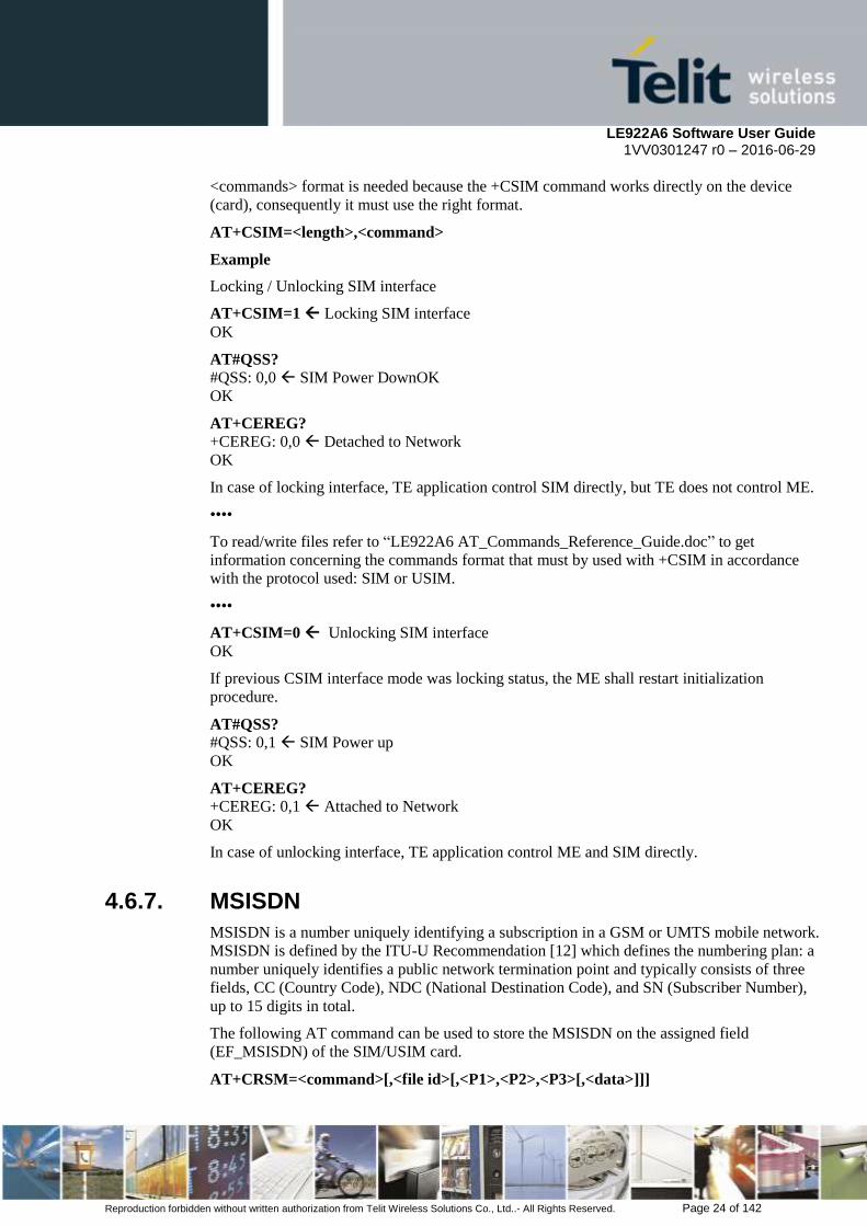
<commands> format is needed because the +CSIM command works directly on the device
(card), consequently it must use the right format.
AT+CSIM=<length>,<command>
Example
Locking / Unlocking SIM interface
AT+CSIM=1 Locking SIM interface
OK
AT#QSS?
#QSS: 0,0 SIM Power DownOK
OK
AT+CEREG?
+CEREG: 0,0 Detached to Network
OK
In case of locking interface, TE application control SIM directly, but TE does not control ME.
••••
To read/write files refer to “LE922A6 AT_Commands_Reference_Guide.doc” to get
information concerning the commands format that must by used with +CSIM in accordance
with the protocol used: SIM or USIM.
••••
AT+CSIM=0 Unlocking SIM interface
OK
If previous CSIM interface mode was locking status, the ME shall restart initialization
procedure.
AT#QSS?
#QSS: 0,1 SIM Power up
OK
AT+CEREG?
+CEREG: 0,1 Attached to Network
OK
In case of unlocking interface, TE application control ME and SIM directly.
4.6.7. MSISDN
MSISDN is a number uniquely identifying a subscription in a GSM or UMTS mobile network.
MSISDN is defined by the ITU-U Recommendation [12] which defines the numbering plan: a
number uniquely identifies a public network termination point and typically consists of three
fields, CC (Country Code), NDC (National Destination Code), and SN (Subscriber Number),
up to 15 digits in total.
The following AT command can be used to store the MSISDN on the assigned field
(EF_MSISDN) of the SIM/USIM card.
AT+CRSM=<command>[,<file id>[,<P1>,<P2>,<P3>[,<data>]]]
LE922A6 Software User Guide 1VV0301247 r0 – 2016-06-29
Reproduction forbidden without written authorization from Telit Wireless Solutions Co., Ltd..- All Rights Reserved. Page 25 of 142
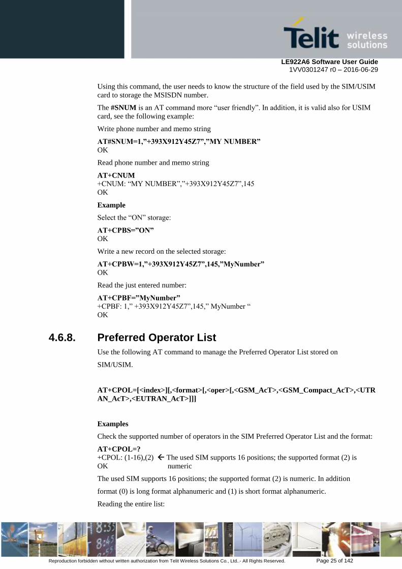
Using this command, the user needs to know the structure of the field used by the SIM/USIM
card to storage the MSISDN number.
The #SNUM is an AT command more “user friendly”. In addition, it is valid also for USIM
card, see the following example:
Write phone number and memo string
AT#SNUM=1,”+393X912Y45Z7”,”MY NUMBER”
OK
Read phone number and memo string
AT+CNUM
+CNUM: “MY NUMBER”,”+393X912Y45Z7”,145
OK
Example
Select the “ON” storage:
AT+CPBS=”ON”
OK
Write a new record on the selected storage:
AT+CPBW=1,”+393X912Y45Z7”,145,”MyNumber”
OK
Read the just entered number:
AT+CPBF=”MyNumber”
+CPBF: 1,” +393X912Y45Z7”,145,” MyNumber “
OK
4.6.8. Preferred Operator List
Use the following AT command to manage the Preferred Operator List stored on
SIM/USIM.
AT+CPOL=[<index>][,<format>[,<oper>[,<GSM_AcT>,<GSM_Compact_AcT>,<UTR
AN_AcT>,<EUTRAN_AcT>]]]
Examples
Check the supported number of operators in the SIM Preferred Operator List and the format:
AT+CPOL=?
+CPOL: (1-16),(2) The used SIM supports 16 positions; the supported format (2) is
OK numeric
The used SIM supports 16 positions; the supported format (2) is numeric. In addition
format (0) is long format alphanumeric and (1) is short format alphanumeric.
Reading the entire list:

LE922A6 Software User Guide 1VV0301247 r0 – 2016-06-29
Reproduction forbidden without written authorization from Telit Wireless Solutions Co., Ltd..- All Rights Reserved. Page 26 of 142
AT+CPOL?
+CPOL: 1,2,”20801”,1,0,0,1
+CPOL: 2,2,”20810”,1,1,0,0
+CPOL: 3,2,”23205”,1,0,1,0
+CPOL: 4,2,”22802”,0,0,0,1
+CPOL: 5,2,”29341”,1,1,1,0
…
+CPOL: 15,2,”23802”,1,1,0,1
+CPOL: 16,2,”24201”,1,0,1,1
OK
The meaning of the string “XXXYY” is: - XXX = Mobile Country Code
- YY = Mobile Network Code
The last 4 digits is GSM, GSM compact, UTRA and EUTRAN access technology
sequentially.
Delete the first entry using a non-existent <format> value just to see the response when the
Extended Error result code is enabled:
AT+CPOL=1,3
+CME ERROR: operation not supported
Now, delete the first entry using the right <format> value:
AT+CPOL=1,2
OK
AT+CPOL?
+CPOL: 2,2,”20810”,1,1,0,0
+CPOL: 3,2,”23205”,1,0,1,0
...
+CPOL: 15,2,”23802”,1,1,0,1
+CPOL: 16,2,”24201”,1,0,1,1
OK
The entry on first position is deleted
AT+CPOL=1,2,20801,1,1,1,1 Write a new entry in the first position
OK
Check if the new entry is written on first position:
AT+CPOL?
+CPOL: 1,2,”20801”,1,1,1,1 The new entry is written on first position
+CPOL: 2,2,”20810”,1,1,0,0
...
+CPOL: 16,2,”24201”,1,0,1,1
OK

LE922A6 Software User Guide 1VV0301247 r0 – 2016-06-29
Reproduction forbidden without written authorization from Telit Wireless Solutions Co., Ltd..- All Rights Reserved. Page 27 of 142
4.7. Network Checking
4.7.1. Query Network Status
4.7.1.1. CS network registration status in UTRAN/E-UTRAN
send command AT+CREG?<cr>
wait for response:
Response Reason Action
+CREG: 0,0
or
+CREG: 1,0
SIM not present or damaged or SIM is
present and PIN is required to continue
operations
Check SIM/UICC or require UICC
insertion and repeat from par.
Error! Reference source not
found.6.1 or
Repeat par. 4.6.2.
+CREG: 0,1
or
+CREG: 1,1
Mobile is registered on its home network. Proceed ahead. Ready to call
+CREG: 0,2
or
+CREG: 1,2
Mobile is currently not registered on any
network but is looking for a suitable one to
register.
Repeat procedure at par. 4.7.1 to
see if it has found a suitable
network to register in.
+CREG: 0,3
or
+CREG: 1,3
Mobile has found some networks but it is not
allowed to register on any of them, no
roaming was allowed.
Try in another place, and repeat
procedure at par. 4.7.1
+CREG: 0,4
or
+CREG: 1,4
Mobile is in an unknown network status Repeat procedure at par. 4.7.1 to
see if it has found a suitable
network to register in
+CREG: 0,5
or
+CREG: 1,5
Mobile has found some networks and is
currently registered in roaming on one of
them
Proceed ahead. Ready to call
4.7.1.2. PS network registration status in UTRAN
send command AT+CGREG?<cr>
wait for response:
Response Reason Action
+CGREG: 0,0
or
+CGREG: 1,0
SIM not present or damaged or
SIM is present and PIN is required to
continue operations
Check SIM/UICC or require UICC
insertion and repeat from par.
Error! Reference source not
found.6.1 or
Repeat par. 4.6.2.
+CGREG: 0,1
or
+CGREG: 1,1
Mobile is registered on its home network. Proceed ahead. Ready to call
+CGREG: 0,2 Mobile is currently not registered on any Repeat procedure at par. 4.7.12 to

LE922A6 Software User Guide 1VV0301247 r0 – 2016-06-29
Reproduction forbidden without written authorization from Telit Wireless Solutions Co., Ltd..- All Rights Reserved. Page 28 of 142
or
+CGREG: 1,2
network but is looking for a suitable one to
register.
see if it has found a suitable
network to register in.
+CGREG: 0,3
or
+CGREG: 1,3
Mobile has found some networks but it is not
allowed to register on any of them, no
roaming was allowed.
Try in another place, and repeat
procedure at par. 4.7.12
+CGREG: 0,4
or
+CGREG: 1,4
Mobile is in an unknown network status Repeat procedure at par. 4.7.12 to
see if it has found a suitable
network to register in
+CGREG: 0,5
or
+CGREG: 1,5
Mobile has found some networks and is
currently registered in roaming on one of
them
Proceed ahead. Ready to call
4.7.1.3. PS network registration status in E-UTRAN
send command AT+CEREG?<cr>
wait for response:
Response Reason Action
+CEREG: 0,0
or
+CEREG: 1,0
SIM not present or damaged
or
SIM is present and PIN is required to
continue operations
Check SIM/UICC or require UICC
insertion and repeat from par.
Error! Reference source not
found.6.1 or
Repeat par. 4.6.2.
+CEREG: 0,1
or
+CEREG: 1,1
Mobile is registered on its home network. Proceed ahead. Ready to call
+CEREG: 0,2
or
+CEREG: 1,2
Mobile is currently not registered on any
network but is looking for a suitable one to
register.
Repeat procedure at par. 4.7.13 to
see if it has found a suitable
network to register in.
+CEREG: 0,3
or
+CEREG: 1,3
Mobile has found some networks but it is not
allowed to register on any of them, no
roaming was allowed.
Try in another place, and repeat
procedure at par. 4.7.13
+CEREG: 0,4
or
+CEREG: 1,4
Mobile is in an unknown network status Repeat procedure at par. 4.7.13 to
see if it has found a suitable
network to register in
+CEREG: 0,5
or
+CEREG: 1,5
Mobile has found some networks and is
currently registered in roaming on one of
them
Proceed ahead. Ready to call
NOTE:
When a response +CREG/+CGREG/+CEREG: x,1 or + CREG/+CGREG/+CEREG: x,5
is received, then the device is ready to place and receive a call or SMS. It is possible to jump
directly to call setup procedures or SMS sending procedures.
4G only products like LE922A6-E1 does not support +CGREG command.

LE922A6 Software User Guide 1VV0301247 r0 – 2016-06-29
Reproduction forbidden without written authorization from Telit Wireless Solutions Co., Ltd..- All Rights Reserved. Page 29 of 142
4.7.2. Network Operator Identification
Once the mobile has registered on some network (or even if it has returned
+CREG/+CGREG/+CEREG:x,3), it is possible to query the mobile for network
identifications, codes and names:
send command AT+COPS=?<cr>
wait for response in the format:
+COPS: [list of supported (<stat>,long alphanumeric <oper>,short alphanumeric
<oper>,numeric <oper>,< AcT>)s]
[,,(list of supported <mode>s),(list of supported <format>s)]
where:
<stat> operator availability
0 - unknown
1 - Available
2 - current
3 - Forbidden
<AcT> access technology selected
0 GSM
2 UTRAN
7 E-UTRAN
NOTE:
Since with this command a network scan is done, this command may require some seconds
before the output is given.
For example:
AT Command
AT+COPS=?<cr>
Answer:
+COPS: (2,"","SKTelecom","45005",7),(3,"KT","KT","45008",7),(3,"KOR LG
Uplus","LG U+","45006",7),,(0-4),(0-2)
OK
In this case the mobile is registered on the network "SKTelecom" which is a network from
Korea, code: 450 and Network ID: 05.
The other network is not available for registration:

LE922A6 Software User Guide 1VV0301247 r0 – 2016-06-29
Reproduction forbidden without written authorization from Telit Wireless Solutions Co., Ltd..- All Rights Reserved. Page 30 of 142
NOTE:
This command issues a network request and it may require quite a long time to respond, since
the device has to wait the answer from the network (it can be as long as 60 seconds). Do not
use this command if not necessary.
4.7.3. Signal Strength & Quality
Assume that the mobile is registered on a Network that can be: GERAN or UTRAN. The
following AT command can be useful to know the received signal strength & quality to have
an indication about the radio link reliability.
AT+CSQ
Examples
Assume that the antenna is not connected to the Telit Module or Network coverage is not
present at all.
AT+CSQ
+CSQ: 99,99
OK
Now, the antenna is connected to the Telit Module and Network coverage is present. Enter
again the previous AT command:
AT+CSQ
+CSQ: 17,0
OK
17 = <rssi> = Received Signal Strength Indication
0 = <ber> = Bit Error Rate
Now, a wrong parameter is entered just to see the result format when Verbose Extended Error
result is enabled
AT+CSQ?
+CME ERROR: operation not supported
4.7.4. Extended Signal Quality
Assume that the mobile is registered on a Network that can be: GERAN ,UTRAN and
EUTRAN.
The following AT command can be useful to know the received signal strength & quality to
have an indication about the radio link reliability.
LE922A6 Software User Guide 1VV0301247 r0 – 2016-06-29
Reproduction forbidden without written authorization from Telit Wireless Solutions Co., Ltd..- All Rights Reserved. Page 31 of 142
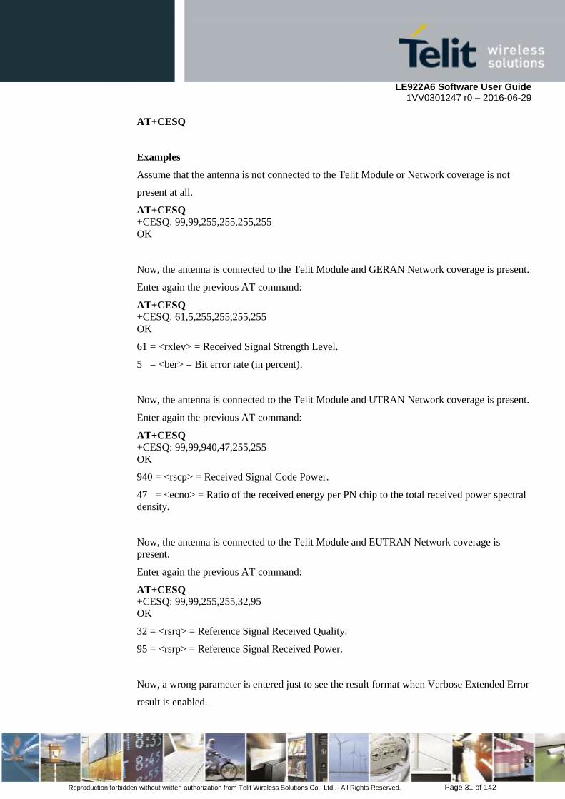
AT+CESQ
Examples
Assume that the antenna is not connected to the Telit Module or Network coverage is not
present at all.
AT+CESQ +CESQ: 99,99,255,255,255,255
OK
Now, the antenna is connected to the Telit Module and GERAN Network coverage is present.
Enter again the previous AT command:
AT+CESQ
+CESQ: 61,5,255,255,255,255
OK
61 = <rxlev> = Received Signal Strength Level.
5 = <ber> = Bit error rate (in percent).
Now, the antenna is connected to the Telit Module and UTRAN Network coverage is present.
Enter again the previous AT command:
AT+CESQ
+CESQ: 99,99,940,47,255,255
OK
940 = <rscp> = Received Signal Code Power.
47 = <ecno> = Ratio of the received energy per PN chip to the total received power spectral
density.
Now, the antenna is connected to the Telit Module and EUTRAN Network coverage is
present.
Enter again the previous AT command:
AT+CESQ +CESQ: 99,99,255,255,32,95
OK
32 = <rsrq> = Reference Signal Received Quality.
95 = <rsrp> = Reference Signal Received Power.
Now, a wrong parameter is entered just to see the result format when Verbose Extended Error
result is enabled.

LE922A6 Software User Guide 1VV0301247 r0 – 2016-06-29
Reproduction forbidden without written authorization from Telit Wireless Solutions Co., Ltd..- All Rights Reserved. Page 32 of 142
AT+CESQ?
+CME ERROR: operation not supported
4.7.5. Fast Network Status Check
Once the Telit Module is registered on a Network, doesn’t matter about the technology (GERAN or UTRAN, E-UTRAN), it could be useful to know the received signal strength and the Network on which the Telit Module is registered. This information can be gathered by means of the following standard AT commands: +CREG, +COPS and +CSQ. These commands are not fast in the response due to Network response time, especially the +COPS command. If the User objective is to keep its Software Application as general as possible, he can use the standard AT commands above mentioned and described on the previous paragraphs.
In addition, Telit Modules provide the user with proprietary AT commands to gather all the information needed in a faster and simpler way, they are:
#MONI
#SERVINFO
#MONIZIP
Use the following AT command to select cells and collect their information:
UTRAN mode
AT#MONI
#MONI: KOR SK Telecom PSC:15 RSCP:-102 LAC:21E1 Id:63809024 EcIo:0.0
UARFCN:10713 PWR:-64dbm DRX:0 SCR:240
OK
E-UTRAN mode
AT#MONI
#MONI: KOR SK Telecom RSRP:-91 RSRQ:-7 TAC:310F Id:135386691 EARFCN:200
PWR:-62dbm DRX:32
OK
UTRAN mode
Collect only the Serving Cell Network Information:
AT#SERVINFO
#SERVINFO: 10713,-64,"KOR SK Telecom","45005",15,21E1,0,3,-0,"I",01,12800
OK
E-UTRAN mode
Collect only the Serving Cell Network Information:

LE922A6 Software User Guide 1VV0301247 r0 – 2016-06-29
Reproduction forbidden without written authorization from Telit Wireless Solutions Co., Ltd..- All Rights Reserved. Page 33 of 142
AT#SERVINFO
#SERVINFO: 200,-61,"KOR SK Telecom","45005",811D643,310F,32,3,-89
OK
UTRAN mode
AT#MONIZIP
#MONIZIP: KOR SK Telecom,15,-102,21E1,63809024,0.0,10713,-64,0,240
OK
E-UTRAN mode
AT#MONIZIP
#MONIZIP: KOR SK Telecom,-91,-7,310F,135386691,200,-62,32
OK
NOTE:
#MONI, #SERVINFO and #MONIZIP commands should be used only to collect Network
Name and Signal Strength information. To check if mobile is registered or is looking for a
suitable network to register on, use +CREG or +CEREG command. In fact, if the network
signal is too weak and mobile loses the registration, until a new network is found the two
commands report the last measured valid values and not the real ones. The TA (timing
advance parameter) is valid only during a call. Check network registration with +CREG or
+CEREG command. When mobile is registered, query the mobile for network operator name
and signal strength with #MONI and #MONIZIP command.
4.7.6. Network Survey
Use the following AT command to perform a quick survey through channels belonging to the
current band.
AT#CSURV[=[<s>,<e>]]
Parameters: <s> - starting channel, <e> - ending channel
Examples
AT#CSURV
Network survey started ...
earfcn: 200 rxLev: -80 mcc: 450 mnc: 05 cellId: 501 tac: 12559
earfcn: 200 rxLev: -94 cellId: 449
earfcn: 200 rxLev: -94 cellId: 419
earfcn: 1350 rxLev: -102 cellId: 252

LE922A6 Software User Guide 1VV0301247 r0 – 2016-06-29
Reproduction forbidden without written authorization from Telit Wireless Solutions Co., Ltd..- All Rights Reserved. Page 34 of 142
earfcn: 1350 rxLev: -102 cellId: 294
earfcn: 1350 rxLev: -102 cellId: 69
uarfcn: 10713 rxLev: -59 mcc: 450 mnc: 05 scr code: 240 cellId: 63809024 lac: 86
73 cellStatus: CELL_SUITABLE rscp: -64 ecio: -5.5
uarfcn: 10836 rxLev: -61 mcc: 450 mnc: 08 scr code: 1488 cellId: 14909569 lac: 7
170 cellStatus: CELL_FORBIDDEN rscp: -66 ecio: -5.5
uarfcn: 10812 rxLev: -63 mcc: 450 mnc: 08 scr code: 1488 cellId: 14909568 lac: 7
170 cellStatus: CELL_FORBIDDEN rscp: -73 ecio: -10.0
uarfcn: 10737 rxLev: -64 mcc: 450 mnc: 05 scr code: 240 cellId: 63809028 lac: 86
73 cellStatus: CELL_SUITABLE rscp: -69 ecio: -5.5
Network survey ended
OK
4.7.7. BCCH Survey
Use the following AT command to perform a quick survey of the channels belonging to the
current band. The survey stops as soon as <n> BCCH carriers are found.
AT#CSURVB=[<n>]
Parameters: <n> - number of desired BCCH carriers.
Examples
AT#CSURVB=2
Network survey started ...
uarfcn: 10713 rxLev: -59 mcc: 450 mnc: 05 scr code: 240 cellId: 63809024 lac: 86
73 cellStatus: CELL_SUITABLE rscp: -64 ecio: -5.5
uarfcn: 10836 rxLev: -61 mcc: 450 mnc: 08 scr code: 1488 cellId: 14909569 lac: 7
170 cellStatus: CELL_FORBIDDEN rscp: -66 ecio: -5.5
Network survey ended
OK
NOTE:
4G/3G only products like LE922A6-A1 does not support GSM access technology. The
#CSURV, #CSURVB could not indicate a survey of the channels that belonging to GSM. 4G

LE922A6 Software User Guide 1VV0301247 r0 – 2016-06-29
Reproduction forbidden without written authorization from Telit Wireless Solutions Co., Ltd..- All Rights Reserved. Page 35 of 142
only products like LE922A6-E1 does not support GSM and UTRAN access technology. So
#CSURVB could not be performed on 4G only products.
4.8. Voice Call Establishment
Before setting up the Voice Call, it is assumed that Telit Module is registered on a network
and the signal strength is enough to carry on a reliable radio link.
4.8.1. Set Module in Voice Mode
Use the following AT command to set up the module for a Voice Call:
AT+FCLASS=8
OK
NOTE:
+FCLASS=8 command may be omitted if the “;” modifier is added at the end of the
ATD command, after the entered phone number.
4.8.2. Dialing a Phone Number
Use the following AT command to dial up a phone number.
ATD<number>[;]
Examples
Assume that the module is set in voice mode: AT+FCLASS=8 has been executed. After that,
call the national number 040-4X92XYX.
ATD0404X92XYX
OK
Now, call the national number 040-4X92XYX in international format +39-040-4X92XYX.
ATD+390404X92XYX
OK
Call the national number 040-4X92XYX in international format +39-040-4X92XYX. The
module is not set in voice mode (AT+FCLASS=8 has not been executed). In this case to
perform the Voice Call the User must use the “;” character at the end of the command.
ATD+390404X92XYX;
OK

LE922A6 Software User Guide 1VV0301247 r0 – 2016-06-29
Reproduction forbidden without written authorization from Telit Wireless Solutions Co., Ltd..- All Rights Reserved. Page 36 of 142
4.8.3. Audio Codec Information
This example is valid for GERAN and UTRAN standards. Use the following AT command to
get codec information about a call.
AT#CODECINFO=<format>,<mode>
OK
Example
AT#CODECINFO=1,1 enable codec information
OK
ATD<phone number>;
OK
#CODECINFO: “HAMR”,”FR”,”EFR”,”HR”,”FAMR”,”HAMR”
NO CARRIER remote hang up
#CODECINFO: “None”,”FR”,”EFR”,”HR”,”FAMR”,”HAMR”
NOTE:
4G only products like LE922A6-E1 does not support this command
4G/3G only products like LE922A6-A1 does not support GERAN standard.
4.8.4. Setting Audio Codec
This example is valid for GERAN and UTRAN standards. Use the following AT command to
select a codec during a call.
AT#CODEC=<codec>
OK
Example
AT#CODEC?
#CODEC: 0 all the codec are enabled
OK
AT#CODECINFO=1,1 enable codec information
OK
ATD<phone number>; establish the call
#CODECINFO: “HAMR”,”FR”,”EFR”,”HR”,”FAMR”,”HAMR”
OK
NO CARRIER remote hang up
#CODECINFO: “None”,”FR”,”EFR”,”HR”,”FAMR”,”HAMR”
LE922A6 Software User Guide 1VV0301247 r0 – 2016-06-29
Reproduction forbidden without written authorization from Telit Wireless Solutions Co., Ltd..- All Rights Reserved. Page 37 of 142
AT#CODEC=1 select FR mode
OK
ATD<phone number>; establish the call
#CODECINFO: “FR”,”FR”
OK
NO CARRIER remote hang up
#CODECINFO: “None”,”FR”
NOTE:
4G only products like LE922A6-E1 does not support this command
4G/3G only products like LE922A6-A1 does not support GERAN standard.
4.8.5. Disconnect a Call
Use the following AT command to hang up the current Voice Call:
ATH
OK
4.8.6. Answering an Incoming Call
When an Incoming Call is recognized, the module sends an Unsolicited Code to DTE. Use the
following AT command to answer to the call:
ATA
OK

LE922A6 Software User Guide 1VV0301247 r0 – 2016-06-29
Reproduction forbidden without written authorization from Telit Wireless Solutions Co., Ltd..- All Rights Reserved. Page 38 of 142
5. Advanced Operations
5.1. Accessing the Phonebook
The user can access, by means of dedicated AT commands, the Phonebooks stored on the
SIM/UICC card or on the module itself (NVM).
The LE922A6 family supports the following Phonebooks:
5.1.1. Preliminary Phonebook Setup
The LE922A6 family supports several SIM phonebook storages:
“SM” – SIM/UICC Phonebook: is used to store and recall phone numbers.
“FD” – SIM/USIM Fixed Dialing-Phonebook: it is accessible by means of the PIN2
code. E.g.: if the “FD” storage holds the following string numbers: 0432, 040, the module
can calls only phone numbers starting with one of the two string numbers.
“LD” – SIM/UICC Last-Dialing-Phonebook: is the list of the last dialed phone numbers,
it is updated automatically. +CPBW command can be only used to delete phone numbers.
“MC” – NVM Missed-Calls-Phonebook: is the list of the received calls not answered. It
is updated automatically. +CPBW command can be only used to delete phone numbers.
“RC” – NVM Received-Calls- Phonebook: is the list of the received and answered calls.
It is updated automatically. +CPBW command can be only used to delete phone numbers.
“MB” – SIM/USIM Mail-Box- Phonebook: is a read only list of the phone mailbox
numbers. The MB must be supported by SIM.
“DC” – NVM Last-Dialing-Phonebook: is the list of the last dialed phone numbers
stored on the module (NVM); it is updated automatically. +CPBW command can be only
used to delete phone numbers.
“ME”- NVM Module Phonebook: is used to store and recall phone numbers.
“EN”- SIM/USIM Emergency List: is a read only list of the emergency phone numbers
stored on SIM
“ON”- SIM (or MT) own numbers (MSISDNs) list (reading of this storage may be
available through +CNUM also). When storing information in the SIM/UICC, if a SIM
card is present or if a UICC with an active GSM application is present, the information in
EFMSISDN under DFTelecom is selected. If a UICC with an active USIM application is present,
the information in EFMSISDN under ADFUSIM is selected.
“SD” – SIM/USIM Service Dialling Numbers (SDN) phonebook :+CPBW is not
applicable for this storage.
To access the storage the user has to choose one. This must be the first Phonebook operation.
Once storage is selected, it is no longer needed to select it again until the desired storage
remains the same and the module is not turned off.

LE922A6 Software User Guide 1VV0301247 r0 – 2016-06-29
Reproduction forbidden without written authorization from Telit Wireless Solutions Co., Ltd..- All Rights Reserved. Page 39 of 142
5.1.1.1. Select Phonebook Memory Storage
Use the following AT command to select the Phonebook Memory Storage:
AT+CPBS=<storage>
Examples
AT+CPBS=? Read the supported range of Phonebook Storages
+CPBS: (“SM”, “FD”, “LD”, “MC”, “RC”) “MB” is not supported by the inserted
SIM/UICC
OK
AT+CPBS? Read the current Phonebook Storage
+CPBS: “SM”,10,250
OK
AT+CPBS=“FD” Select “FD” phonebook storage
ERROR
AT+CMEE=2
OK
AT+CPBS=“FD”
+CME ERROR: SIM PIN2 required
AT+CPIN=PIN2 Enter PIN2
OK
AT+CPBS=“FD” Select “FD” phonebook storage
OK
NOTE:
the last two commands can be substituted by the following one:
AT+CLCK=“FD”,1,PIN2
OK
AT+CPBS=“MC” Select “MC” Phonebook Storage
OK
AT+CPBS? +CPBS: “MC”,0,20
OK
NOTE:
after module power on and PIN authentication, the module reads the data records stored on
the SIM/UICC. During this activity the phonebook access is inhibited for a time interval
depending on various factors. If Phonebook commands are entered during this interval the
module returns an error message. In this case, retry the operations later.
LE922A6 Software User Guide 1VV0301247 r0 – 2016-06-29
Reproduction forbidden without written authorization from Telit Wireless Solutions Co., Ltd..- All Rights Reserved. Page 40 of 142
AT+CPBS=? Read the supported range of Phonebook Storages
+CPBS: (“SM”, “FD”, “LD”, “MC”, “RC”, “DC”, “ME”, “EN”, “ON”)
OK
AT+CPBS? Read the current Phonebook Storage
+CPBS: “SM”,19,250
OK
5.1.1.2. Search Phonebook Entries
Use the following AT command to search a Phonebook entry.
AT+CPBF=<findtext>
Examples
Read the current Phonebook storage and select “SM” storage:
AT+CPBS?
+CPBS: “MC”,0,20
OK
AT+CPBS=”SM”
OK
AT+CPBS?
+CPBS: “SM”,10,250
OK
Look for entries having name starting with: “FA” on the selected storage:
AT+CPBF=”FA”
+CPBF: 7,”+39404192369”,145,”Fabio” +CPBF: 9,”0404X92XYX”,129,”Fabrizio”
OK
Look for an entry not present on the selected storage. Before doing that verify if the Extended
Error result code is enabled.
AT+CMEE?
+CMEE: 2
OK
AT+CPBF=”FAUSTO”
+CME ERROR: not found
NOTE:

LE922A6 Software User Guide 1VV0301247 r0 – 2016-06-29
Reproduction forbidden without written authorization from Telit Wireless Solutions Co., Ltd..- All Rights Reserved. Page 41 of 142
the search for <name> string is not case sensitive and the string may or may not be included
in double brackets
5.1.2. Read Phonebook Entries
Use the following AT command to read a Phonebook entry:
AT+CPBR=<index1>[,<index2>]
Examples
Select “SM” storage:
AT+CPBS=”SM”
OK
Look for the entry at the position index = 7:
AT+CPBR=7
+CPBR: 7,”+39404192369”,145,”Fabio”
OK
Look for the entries from position 7 up to position 9:
AT+CPBR=7,9
+CPBR: 7,”+39404192369”,145,”Fabio”
+CPBR: 9,”0404X92XYX”,129,”Fabrizio”
OK
The position 8 is empty.
5.1.3. Write Phonebook Entry
Use the following AT command to write a Phonebook entry:
AT+CPBW=[<index>][,<number>[,<type>[,<text>]]]
Examples
Select the “SM” phonebook:
AT+CPBS=”SM”
OK
Write a new record on the first free position of the selected “SM” phonebook:
AT+CPBW=,”0404192123”,129,”NewRecord”
OK
AT+CPBF=”NEW”
+CPBF: 8,”0404192123”,129,”NewRecord”
OK

LE922A6 Software User Guide 1VV0301247 r0 – 2016-06-29
Reproduction forbidden without written authorization from Telit Wireless Solutions Co., Ltd..- All Rights Reserved. Page 42 of 142
5.1.4. Delete Phonebook Entry
First, the desired storage must be active (see par.5.1.1.1). Then:
Use the following AT command with only <index> parameter to delete a Phonebook entry:
AT+CPBW=<index>
Examples
Select the “SM” phonebook:
AT+CPBS=”SM”
OK
Delete record 7 on the “SM” phonebook:
AT+CPBW= 7
OK
Try to delete a non-existent record on the “SM” phonebook, just to see the format response:
AT+CPBF=99999999999
+CME ERROR: not found
NOTE:
The delete command overwrites the <index> record number with an empty record.
5.2. LTE Power Saving Function
The Telit LE922A6 family has a special function that reduces power consumption during idle
time, thus allowing a longer standby time with a given battery capacity.
This function monitors the DTR line and USB VBUS line indicating that the OEM
application is ready to send commands when DTR goes high and USB VBUS goes low (0V
on USB). If so, the OEM application is not going to send any commands and the LE922A6
family module can save energy by shutting down its internal serial port or USB port.
When the OEM application becomes ready again, the line DTR is tied low (0V on UART) or
VBUS is tied high; the LE922A6 family detect this condition and powers up the serial port or
USB port.
If the power saving function is activated, then the serial port must support the DTR line since
when this line is high (Data Terminal is NOT ready) and the USB port must support the
VBUS line since when this line is Low the device goes into a sleep condition and will not
respond to commands until the DTR is tied low (Data Terminal is ready) or the VBUS is tied
high.
5.2.1. Enabling/Disabling the Power Saving Function
send command AT+CFUN=<fun><cr>
LE922A6 Software User Guide 1VV0301247 r0 – 2016-06-29
Reproduction forbidden without written authorization from Telit Wireless Solutions Co., Ltd..- All Rights Reserved. Page 43 of 142
where:
<fun> is the power saving function mode, the supported values are:
0 - minimum functionality, NON-CYCLIC SLEEP mode: in this mode, the AT interface is
not accessible.
1 - mobile full functionality with power saving disabled (factory default)
4 - disable both TX and RX
5 - mobile full functionality with power saving enabled
wait for response:
Response Reason Action
OK The power save is now active
ERROR some error occurred Enable extended result codes
and retry with +CMEE
+CME ERROR: 4 operation not supported Check command syntax and <fun>
value.
5.2.2. Power Saving Mode
Power Saving Mode means that Device is in sleep mode with disabling the interface
(UART/USB).
LE922A6 FAMILY makes it possible for DTE to receive the event such as incoming
call/SMS/data while both DTE and Modem are in sleep mode with disabling all serial
interfaces.
DTE must require below specification to achieve the reduction of power consumption.
DSR/DTR/RI pin control on Main UART port.
USB VBUS control
If DTE satisfies above requirement, LE922A6 FAMILY can provide the functionalities:
Keep URC message.
Keep Incoming data during data mode, until DTE wake up from sleep mode.
LE922A6 FAMILY helps DTE to reduce their power consumption using below rules.
Use RI on Main UART to wake up DTE from sleep mode. (DTE must always
monitor RI pin during power saving mode).
Use DTR on Main UART to place Modem in sleep mode or wake up Modem from
sleep mode.
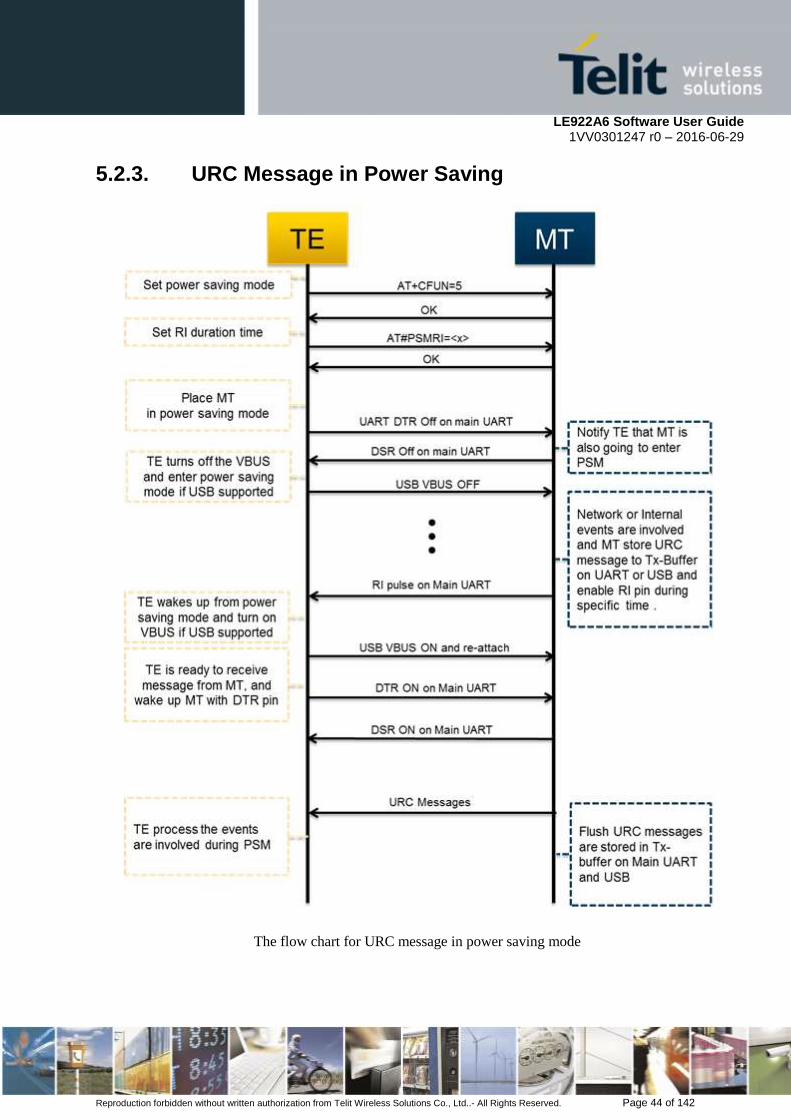
LE922A6 Software User Guide 1VV0301247 r0 – 2016-06-29
Reproduction forbidden without written authorization from Telit Wireless Solutions Co., Ltd..- All Rights Reserved. Page 44 of 142
5.2.3. URC Message in Power Saving
The flow chart for URC message in power saving mode

LE922A6 Software User Guide 1VV0301247 r0 – 2016-06-29
Reproduction forbidden without written authorization from Telit Wireless Solutions Co., Ltd..- All Rights Reserved. Page 45 of 142
Above figure illustrates the action flow to get URC messages are invoked while both DTE
and modem in sleep mode.
LE922A6 FAMILY keeps the URC messages are listed in the table below and these URCs
can be enabled or disabled by AT command.
URC message List
URC Message Enable/Disable AT Command
RING Always enabled
+CIEV +CIND
+CEREG +CEREG
+CMTI,+CMT,+CBM,+CDS,+CDSI +CNMI
#TEMPMEAS #TEMPMON
#MWI #MWI
SRING Always enabled
+CALA +CALA
#QSS #QSS
VBUS Control System
Product VBUS Master
LE922A6 FAMILY DTE ( must turn off VBUS when entering to sleep mode and turn on
VBUS when waking up from sleep mode )
NOTE:
DTE get URC messages kept on Main UART/Telit USB Modem/Aux in power saving mode.
But LE922A6 FAMILY can’t keep URC messages larger than 8K bytes. We recommend that
DTE should get the URC message as soon as RI signal is generated on Main UART.
5.2.4. RI Signal for the Specific Event
DTE can wake up from sleep mode by monitoring RI pin, while it‘s in sleep mode. LE922A6
FAMILY provides different RI signal type to DTE, according to the specific event.
This paragraph deals with the following items:
RI Signal for incoming call
RI Signal for incoming SMS
RI Signal for TCP connection request in server mode
RI Signal for URC message during power saving mode
5.2.4.1. RI Signal for Incoming Call
RI signal for incoming call has different signal in accordance with the value of \R and RING
message is sent to DTE the instance RI signal is going to is activated, periodically.
In case the value of \R is 0 or 1, RI signal and RING message like as the following figure is
generated.

LE922A6 Software User Guide 1VV0301247 r0 – 2016-06-29
Reproduction forbidden without written authorization from Telit Wireless Solutions Co., Ltd..- All Rights Reserved. Page 46 of 142
In case the value of \R is 2, RI signal and RING message is generated like as the following figure
5.2.4.2. RI Signal for Incoming SMS
RI signal for incoming SMS has two types in accordance with the value of +CNMI or
#E2SMSRI. In case +CNMI=3 (On-line data mode), the negative going pulse like as the
following figure is generated, one time.
In case #E2SMSRI = <x>, the negative going pulse like as the following figure is generated,
one time.
1000 ms
RI Signal for +CNMI=3 (On-line data mode)
4000ms 1000ms
RING
1000ms
RING
4000ms
RI signal for \R2
1000ms
RING
4000ms
RING
1000ms 4000ms
RI signal for \R0 or \R1

LE922A6 Software User Guide 1VV0301247 r0 – 2016-06-29
Reproduction forbidden without written authorization from Telit Wireless Solutions Co., Ltd..- All Rights Reserved. Page 47 of 142
Note: In case both +CNMI=3(On-line data mode) and #E2SMSRI=<x> is issued, RI signal
behavior by #E2SMSRI is ignored by +CNMI
5.2.4.3. RI Signal for Socket Listen
RI Signal is generated, when modem receive TCP connection request from remote client
during socket server mode. This signal is the negative going pulse and is generated, one time.
5.2.4.4. RI Signal for Events in Power Saving Mode
RI Signal for URC message and incoming data is generated, only when modem is in power
saving mode. #PSMRI must be set as the value is not 0. DTE issue AT+CFUN=5 and Drop
DTR pin on main UART to place modem in the power saving mode.
Note: if RI signal for Incoming Call, SMS, Socket Listen and #PSMRI are generated at the
same time in power saving mode, RI signal for #PSMRI will be ignored.
RI Signal for #PSMRI
#PSMRI value (50 ~11500 ms)
RI Signal for #E2SLRI
#E2SLRI value (50 ~11500 ms)
RI Signal for #E2SMSRI
#E2SMSRI value
(50 ~11500 ms)

LE922A6 Software User Guide 1VV0301247 r0 – 2016-06-29
Reproduction forbidden without written authorization from Telit Wireless Solutions Co., Ltd..- All Rights Reserved. Page 48 of 142
5.3. SMS Handling
The Telit LE922A6 family supports the Short Message Service, it is possible to store, delete,
write, send and receive a SMS, which is a short text message up to 160 characters long.
5.3.1. SMS Device setup
Before accessing the Short Message Service, the device has to be properly set up.
5.3.1.1. Select SMS Format Type
The LE922A6 family supports SMS in two different formats:
PDU
Text
The difference is that in the PDU mode the device returns and receives SMS encoded in the
format ready to be sent to the network; in TEXT mode the device converts automatically the
read PDU into text and vice versa. By using TEXT mode, the PDU data encoding knowledge
is not needed and operations are easier. For this reason, we are using the TEXT mode to
explain how to operate with SMS. If you are familiar with PDU encoding then you can
operate with PDU by selecting that format and using appropriate command syntax.
Send command AT+CMGF=<mode><cr>
Where:
<mode> is the SMS format type:
0 - PDU
1 - Text
wait for response OK
NOTE:
This setting is stored and remains until the device is turned off. Hence, there is no need to
issue it more than one time. For TEXT mode use <mode>=1.
For example:
1- Let us assume you want to set TEXT format for the SMS:
command
AT+CMGF=1<cr>
response:
OK
LE922A6 Software User Guide 1VV0301247 r0 – 2016-06-29
Reproduction forbidden without written authorization from Telit Wireless Solutions Co., Ltd..- All Rights Reserved. Page 49 of 142
5.3.1.2. Check SMS Service Centre Number
The SMS are sent by the LE922A6 family to a service center (SMSC) where the message is
dispatched towards its final destination or is kept until the delivery is possible. To ensure a
correct behavior of this service the number of the service center must be the one your network
operator supports.
To check which number is stored as the SMSC:
send command AT+CSCA?<cr>
wait for response in the format: +CSCA: <number>,<type>
OK
where:
<number> is the SMSC number
<type> is the SMSC number type:
145 - international numbering scheme (number begins with "+")
129 - national numbering scheme
NOTE:
This setting remains stored in the SIM/UICC card until it is changed or deleted, so this
operation may be done only once if the SIM/UICC Card is not changed. The setting is
maintained even after power down.
For example:
1- Let us assume you want to check your SMSC number:
command
AT+CSCA? <cr>
response:
+CSCA: +393359609600
OK
5.3.1.3. Add SMS Service Centre Number (only if required)
If your previously check for SMSC returned an empty field:
+CSCA: ,129
Or if the SMSC number stored does not correspond to the desired one, then the new number
has to be stored. In this way, the previously stored number will be overwritten.
send command AT+CSCA=<number>,<type><cr>
where:

LE922A6 Software User Guide 1VV0301247 r0 – 2016-06-29
Reproduction forbidden without written authorization from Telit Wireless Solutions Co., Ltd..- All Rights Reserved. Page 50 of 142
<number> is the desired SMSC number
<type> is the SMSC number type:
145 - international numbering scheme (number begins with "+")
129 - national numbering scheme
wait for OK
For example:
1- Let us assume your desired SMSC number is +39335123456 (stored in international
format):
command
AT+CSCA=+39335123456,145<cr>
response:
OK
5.3.1.4. Select New Messages Indication Behavior
When the device receives a new message an unsolicited indication is generated, this
indication may be sent to the DTE, buffered if the DTE is busy (for example during a data
call) or discarded.
To set the desired behavior:
send command
AT+CNMI=<mode>,<mt>,<bm>,<ds>,<bfr><cr>
where:
Set command selects the behaviour of the device on how the receiving of new messages from
the network is indicated to the DTE.
Parameter:
<mode> - unsolicited result codes buffering option
0 - Buffer unsolicited result codes in the TA. If TA result code buffer is full, indications can
be buffered in some other place or the oldest indications may be discarded and replaced with
the new received indications.
1 - Discard indication and reject new received message unsolicited result codes when TA-TE
link is reserved, otherwise forward them directly to the TE.
2 - Buffer unsolicited result codes in the TA in case the DTE is busy and flush them to the TE
after reservation. Otherwise forward them directly to the TE.
3 - Forward unsolicited result codes directly to the TE. The hardware Ring line Indicator for 1
second is enabled when a new message is received while the module is in EPS on-line data
mode.
<mt> - result code indication reporting for SMS-DELIVER
0 - No SMS-DELIVER indications are routed to the TE.

LE922A6 Software User Guide 1VV0301247 r0 – 2016-06-29
Reproduction forbidden without written authorization from Telit Wireless Solutions Co., Ltd..- All Rights Reserved. Page 51 of 142
1 - If SMS-DELIVER is stored into ME/TA, indication of the memory location is routed to
the TE using the following unsolicited result code:
+CMTI: <memr>,<index>
where:
<memr> - memory storage where the new message is stored
"SM"
"ME"
"SR"
<index> - location on the memory where SM is stored.
2 - SMS-DELIVERs (except class 2 messages and messages in the message waiting
indication group) are routed directly to the TE using the following unsolicited result code:
(PDU Mode)
+CMT: <alpha>,<length><CR><LF><pdu>
where:
<alpha> - alphanumeric representation of originator/destination number corresponding to the
entry found in MT phonebook
<length> - PDU length
<pdu> - PDU message
(TEXT Mode)
+CMT:<oa>,<alpha>,<scts>[,<tooa>,<fo>,<pid>,<dcs>,
<sca>,<tosca>,<length>]<CR><LF><data> (the information written in italics will be
present depending on +CSDH last setting)
where:
<oa> - originating address, string type converted in the currently selected character set (see
+CSCS)
<alpha> - alphanumeric representation of <oa>; used character set must be the one selected
with either command +CSCS.
<scts> - arrival time of the message to the SC
<tooa>, <tosca> - type of number <oa> or <sca>:
129 - number in national format
145 - number in international format (contains the "+")
<fo> - first octet of 3gpp 03.40/23.040
<pid> - Protocol Identifier
<dcs> - Data Coding Scheme
<sca> - Service Centre address, string type, converted in the currently selected character set
(see +CSCS)

LE922A6 Software User Guide 1VV0301247 r0 – 2016-06-29
Reproduction forbidden without written authorization from Telit Wireless Solutions Co., Ltd..- All Rights Reserved. Page 52 of 142
<length> - text length
<data> - TP-User-Data
Class 2 messages and messages in the message waiting indication group (stored message)
result in indication as defined in <mt>=1.
3 - Class 3 SMS-DELIVERs are routed directly to TE using unsolicited result codes defined
in <mt>=2. Messages of other data coding schemes result in indication as defined in <mt>=1.
<bm> - broadcast reporting option
0 - Cell Broadcast Messages are not sent to the DTE
2 - New Cell Broadcast Messages are sent to the DTE with the unsolicited result code:
(PDU Mode)
+CBM: <length><CR><LF><PDU>
where:
<length> - PDU length
<PDU> - message PDU
(TEXT Mode)
+CBM:<sn>,<mid>,<dcs>,<pag>,<pags><CR><LF><data>
where:
<sn> - message serial number
<mid> - message ID
<dcs> - Data Coding Scheme
<pag> - page number
<pags> - total number of pages of the message
<data> - CBM Content of Message
<ds> - SMS-STATUS-REPORTs reporting option
0 - status report receiving is not reported to the DTE
1 - the status report is sent to the DTE with the following unsolicited result code:
(PDU Mode)
+CDS: <length><CR><LF><PDU>
where:
<length> - PDU length
<PDU> - message PDU
(TEXT Mode)
+CDS: <fo>,<mr>,<ra>,<tora>,<scts>,<dt>,<st>
where:

LE922A6 Software User Guide 1VV0301247 r0 – 2016-06-29
Reproduction forbidden without written authorization from Telit Wireless Solutions Co., Ltd..- All Rights Reserved. Page 53 of 142
<fo> - first octet of the message PDU
<mr> - message reference number
<ra> - recipient address, string type, represented in the currently selected character set (see
+CSCS)
<tora> - type of number <ra>
<scts> - arrival time of the message to the SC
<dt> - sending time of the message
<st> - message status as coded in the PDU
2 - if a status report is stored, then the following unsolicited result code is sent:
+CDSI: <memr>,<index>
where:
<memr> - memory storage where the new message is stored
"SR"
<index> - location on the memory where SM is stored
<bfr> - buffered result codes handling method:
0 - TA buffer of unsolicited result codes defined within this command is flushed to the TE
when <mode>=1..3 is entered (OK response must be given before flushing the codes)
1 - TA buffer of unsolicited result codes defined within this command is cleared when
<mode>=1..3 is entered.
NOTE: Issuing AT+CNMI<CR> is the same as issuing the Read command.
NOTE: Issuing AT+CNMI=<CR> is the same as issuing the command AT+CNMI=0<CR>.
wait for OK
NOTE:
In this command description the values that are always 0 are parameter reserved for future
use, in the current software revision the only value supported is 0.
For example:
1- Let us assume you want to eliminate all the unsolicited codes that may be sent when
receiving SMS & Status Report:
Command
AT+CNMI= 0,0,0,0,0<cr>
Response:
OK
For example about a new message indication:

LE922A6 Software User Guide 1VV0301247 r0 – 2016-06-29
Reproduction forbidden without written authorization from Telit Wireless Solutions Co., Ltd..- All Rights Reserved. Page 54 of 142
1- Let us assume you receive a new SMS delivery (AT+CNMI=1,1,0,0,0) and this new
message is stored on the SIM/UICC "SM" storage at the location number 7; the unsolicited
code you will receive (if code is enabled) is:
Unsolicited code:
+CMTI: "SM",7
2- Let us assume you receive a new SMS Status Report delivery (AT+CNMI=1,0,0,2,0) and
this new message is stored on the SIM/UICC "SR" storage at the location number 8; the
unsolicited code you will receive is:
Unsolicited code:
+CDSI: "SR",8
5.3.1.5. Set Text Mode Parameters (only in TEXT mode)
When the device is set to operate with Text SMS not with PDU, the SMS parameters that
usually reside on the header of the PDU must be set apart with the command +CSMP.
The parameters to be set are:
Message Format
Validity Period
Protocol Identifier
Data Coding Scheme
The meaning and format of the parameters is:
Message format, like defined for the first octet of message according to GSM 3.40/23.040:
The format is an 8-bit parameter divided into 6 fields and then reported as an integer:
b7 b6 b5 b4 b3 b2 b1 b0
RP UDHI SRR VPF RD MTI
Where
MTI message type parameter:
0 1 - SMS Submit
0 1 - SMS DELIVER
RD rejects duplicates parameter
0 – do not reject duplicates SMS in SC
1 - reject duplicates on SC
VPF validity period format
0 0 - Validity period NOT present
1 0 - VP integer represented (relative)
1 1 - VP semi octet represented (absolute)
0 1 - reserved

LE922A6 Software User Guide 1VV0301247 r0 – 2016-06-29
Reproduction forbidden without written authorization from Telit Wireless Solutions Co., Ltd..- All Rights Reserved. Page 55 of 142
SRR status report request
0 - status report not requested
1 - status report requested
UDHI user data Header Information
0 - No Header on PDU
1 - Header present on PDU
RP reply path
0 - RP not set
1 - RP set
Validity Period numerical if in relative format or string if in absolute format
This parameter represents the validity period for the SMS after which the message must be
disregarded instead of being delivered.
If in relative format (see VPF parameter) it is an integer:
0 to 143 - corresponding to (VP + 1) x 5 minutes
144 to 167 - corresponding to 12 hours + ((VP -143) x 30 minutes)
168 to 196 - corresponding to (VP - 166) x 1 day
197 to 255 - corresponding to (VP - 192) x 1 week
If in absolute format it is a string in the format:
"gg/MM/YY,hh:mm:ss±tz"
where
gg day of expiration (2 characters)
MM month of expiration (2 characters)
YY year of expiration (2 characters)
hh hour of expiration (2 characters)
mm minute of expiration (2 characters)
ss second of expiration (2 characters)
± sign of the time zone (+ or -)
tz time zone (2 characters)
Protocol Identifier in numerical format: This parameter identifies the protocol used by the
receiver entity and informs the SC that the conversion from SMS to that protocol must be
done while delivering the message.
Protocol ID Conversion towards
0 Implicit (default)
33 telex (or teletex reduced to telex format)
34 group 3 telefax

LE922A6 Software User Guide 1VV0301247 r0 – 2016-06-29
Reproduction forbidden without written authorization from Telit Wireless Solutions Co., Ltd..- All Rights Reserved. Page 56 of 142
35 group 4 telefax
36 voice telephone (i.e. conversion to speech)
37 ERMES (European Radio Messaging
System)
38 National Paging system (known to the SC)
39 Videotex (T.100/T.101)
40 teletex, carrier unspecified
41 teletex, in PSPDN
42 teletex, in CSPDN
43 teletex, in analog PSTN
44 teletex, in digital ISDN
45 UCI (Universal Computer Interface, ETSI
DE/PS 3 01-3)
46-47 (reserved, 2 combinations)
48 a message handling facility (known to the
SC)
49 any public X.400-based message handling
system
50 Internet Electronic Mail
51-55 (reserved, 5 combinations)
56-62 values specific to each SC, usage based on
mutual agreement between the SME and
the SC (7 combinations available for each
SC)
63
A GSM mobile station. The SC converts
the SM from the received TP-Data-
Coding-Scheme to any data coding scheme
supported by that MS (e.g. the default).
64 Short Message Type 0
65 Replace Short Message Type 1
66 Replace Short Message Type 2
67 Replace Short Message Type 3
68 Replace Short Message Type 4
69 Replace Short Message Type 5
70 Replace Short Message Type 6
71 Replace Short Message Type 7
72..94 Reserved
95 Return Call Message
96..126 Reserved
127 SIM/USIM Data download
Data coding Scheme as defined by GSM 3.38 - in numerical format The DCS is an 8-bit
parameter reported as an integer, the default value is 0, otherwise for simplicity, we report
only the most useful DCS, for further Schemes refer to GSM 3.38
B7 B6 b5 b4 b3 b2 b1 b0
1 1 1 1 0 Alphabet Class
where

LE922A6 Software User Guide 1VV0301247 r0 – 2016-06-29
Reproduction forbidden without written authorization from Telit Wireless Solutions Co., Ltd..- All Rights Reserved. Page 57 of 142
Alphabet
0 - default Alphabet
1 - 8 bit
Class
0 0 - Class 0
0 1 - Class 1
1 0 - Class 2
1 1 - Class 3
NOTE:
The default value for DCS = 0 represents the default SMS sent by a mobile. If you do not
need any particular data coding scheme use DCS=0.
Not all the DCS combinations described in the 3gpp 3.38/23.038 are supported, both by the
network and by the Telit LE922A6. Some features may be not implemented at network level
or at device level, resulting in a +CME ERROR: 3 (operation not allowed) result code. If this
happens then use a different DCS.
send command AT+CSMP=<fo>,<vp>,<pid>,<dcs><cr>
where:
<fo>: Message format
<vp>: Validity Period
<pid>: Protocol Identifier
<dcs>: Data coding Scheme
wait for OK
For example:
1- Let us assume you want to set the SMS parameters to the values:
Message Format:
SMS submit
do not reject duplicates
VP Format integer (relative)
status report not requested
No Header on PDU
Reply path not set
Hence, the message format is the binary number 00010001 corresponding to the integer 17.
Validity period 24 hours corresponding to an integer value 167. 12 hours + ((167 -
143) x 30 min) = 24 hours

LE922A6 Software User Guide 1VV0301247 r0 – 2016-06-29
Reproduction forbidden without written authorization from Telit Wireless Solutions Co., Ltd..- All Rights Reserved. Page 58 of 142
Protocol ID implicit (SMS sent to a mobile terminal) corresponding to a value 0.
DCS default value 0.
command
AT+CSMP= 17,167,0,0
response:
OK
2- Let us assume you want to set the SMS parameters to the values:
Message Format:
SMS submit
do not reject duplicates
VP Format semi octet (absolute)
status report requested
No Header on PDU
Reply path not set
Hence, the message format is the binary number 00111001 corresponding to the integer 57.
Validity period format is absolute, hence it represents the expiration date of the message and
the desired expiration date is for example 29/06/02 at 02:20 in the time zone of Italy (+1).
"29/06/02,02:20:00+1"
Protocol ID implicit (SMS sent to a mobile terminal) corresponding to a value 0.
Data Coding Scheme:
Default Alphabet
Class 0 (e.g. immediate display SMS)
Corresponding to the binary number 11110000 corresponding to the integer 240.
command
AT+CSMP= 57,29/06/02,02:20:00+1,0,240
response:
OK
5.3.1.6. Select SMS Memory and Check for Memory Space
There are various types of storage where the SMS can be stored, the Telit LE922A6 family
provides two different storage:
"ME" - Mobile Equipment memory
"SM" - SIM/USIM Card memory
"SR" – Status report

LE922A6 Software User Guide 1VV0301247 r0 – 2016-06-29
Reproduction forbidden without written authorization from Telit Wireless Solutions Co., Ltd..- All Rights Reserved. Page 59 of 142
The SMS are usually stored (this is true for both the originated and the received SMS) in the
SM/ME storage.
The LE922A6 family allows the user to select a different storage for the read-delete, write-
send, and reception-saving SMS operations.
send command AT+CPMS=<memr>,<memw>,<mems><cr>
where:
<memr>: memory storage for Read and Delete commands
- "SM"
- "ME"
- "SR"
<memw>: memory storage for Write and Send commands
<mems>: memory storage for new incoming message saving
wait for response in the format:
+CPMS:<usedr>,<totalr>,<usedw>,<totalw>,<useds>,<totals>
OK
where
<usedr> - number of SMS stored into <memr>
<totalr> - max number of SMS that <memr> can contain
<usedw> - number of SMS stored into <memw>
<totalw> - max number of SMS that <memw> can contain
<useds> - number of SMS stored into <mems>
<totals> - max number of SMS that <mems> can contain
From this response you can check if the selected storage has room for new SMSs, the free
positions in the storage X (where X can be r,w,s) are <totalX> -<usedX>.
5.3.2. IRA Character Set
The character set used in SMS text mode is the IRA. This set defines each char as a 7-bit
value, hence from 0x00 to 0x7F. The table below reports all the chars supported and their
hexadecimal code. To obtain the code for a char in the table remember that in the row it is
reported the least significant nibble (4 bits) and in the column the most significant nibble. The
empty cells correspond to reserved combinations.
Most Significant Nibble
0x 1x 2x 3x 4x 5x 6x 7x
Lea
st
Sig
nif
ican
t
Nib
bl
e
x0 SP1 0 @ P p
x1 ! 1 A Q a q
x2 " 2 B R b r

LE922A6 Software User Guide 1VV0301247 r0 – 2016-06-29
Reproduction forbidden without written authorization from Telit Wireless Solutions Co., Ltd..- All Rights Reserved. Page 60 of 142
x3 # 3 C S c s
x4 $ 4 D T d t
x5 % 5 E U e u
x6 & 6 F V f v
x7 ' 7 G W g w
x8 ( 8 H X h x
x9 ) 9 I Y i y
xA LF2 * : J Z j z
xB + ; K k
xC , < L l
xD CR3 - = M m
xE . > N n
xF / ? O £ o 1 - SP stands for space character 2 - LF stands for Line Feed character 3 - CR stands for Carriage Return character
For example:
1- Let us assume you want to find the IRA code for the character '&':
From the table you find:
most significant Nibble: 2
least significant Nibble: 6
Hence the IRA code for the '&' character is the hexadecimal 0x26.
2- Let us assume you have the IRA code 0x6B and you want to find the corresponding
character:
From the table you find at the position
most significant Nibble: 6
least significant Nibble: B
Hence, the character corresponding to the 0x6B IRA code is 'k'.
NOTE:
With the command AT+CSCS is possible to select the character set; the available types are:
“GSM” - GSM 7 bit default alphabet
“IRA” - ITU-T.50
”8859-1” - ISO 8859 Latin 1
”PCCP437” - PC character set Code Page 437.
”UCS2” - 16-bit universal multiple-octet coded character set (ISO/IEC10646)
Please refer to the AT command specification for the full command description.

LE922A6 Software User Guide 1VV0301247 r0 – 2016-06-29
Reproduction forbidden without written authorization from Telit Wireless Solutions Co., Ltd..- All Rights Reserved. Page 61 of 142
5.3.3. Writing a New SMS to Storage
A new SMS can be written in the selected storage <memw> (in the current SW version only
"SM" is supported) and then can be sent to the desired destination.
To write the new SMS:
send command AT+CMGW="<da>"<cr>
where:
<da>: destination address
wait for prompt ">"
send SMS text
end command with CTRL-Z character (0x1A hexadecimal) or abort command with
ESC character (0x1B hexadecimal)
wait for response:
Response Reason Action
+CMGW: <index>
OK
Message has been successfully
written in position number
<index>
proceed ahead
ERROR some error occurred Enable the extended error codes
report and retry.
+CMS ERROR: 330 SMSC address unknown Insert SMSC address (see
par. 5.3.1.3)
+CMS ERROR: 322 Memory Full Memory is full, hence delete some
records and retry.
NOTE:
if command is aborted with ESC character, then only the OK result code is returned.
For example:
1- Let us assume you want to write a new SMS to the storage and the destination address is
the number +39338123456789. We suppose you already have set up the device for text SMS
mode as described on the previous paragraphs:
command
AT+CMGW="+39338123456789"
response:
>
now you can insert the message text in IRA format (note that the IRA format and ASCII
format coincide for the alphabet characters but not for the other).
…here will be inserted the SMS message text…
conclude text with the character CTRL-Z

LE922A6 Software User Guide 1VV0301247 r0 – 2016-06-29
Reproduction forbidden without written authorization from Telit Wireless Solutions Co., Ltd..- All Rights Reserved. Page 62 of 142
response:
+CMGW: 3
OK
In this case, the new SMS was successfully written to the location index 3 of the selected
write memory.
5.3.4. Sending an SMS Previously Stored
An already written SMS can be sent from the selected storage <memw>.
To send the written SMS its location index is needed:
send command AT+CMSS=<index><cr>
where:
<index>: SMS location index
wait for response:
Response Reason Action
+CMSS: <mr>
OK
Message has been successfully
sent. <mr> represents the message
reference number.
proceed ahead
ERROR some error occurred Enable the extended error codes
report and retry.
+CMS ERROR: 330 SMSC address unknown Insert SMSC address (see
par. 5.3.1.3)
+CMS ERROR: 41 "Temporary Failure", may be that
the device is not registered on any
network
Check for signal strength and
network registration
+CMS ERROR: 331 No network service Check for signal strength and
network registration
+CMS ERROR: 1 Unassigned number The destination address number
does not exist. Check it and repeat
command.
+CMS ERROR: 42 network congestion Retry later
+CMS ERROR: 96 Mandatory information missing Check for destination address in
the SMS, overwrite it and retry.
For example:
1- Let us assume you want to send a SMS that was written to the storage index position
number 3. We suppose you already have set up the device for text SMS mode as described on
the previous paragraphs:
command
AT+CMSS=3

LE922A6 Software User Guide 1VV0301247 r0 – 2016-06-29
Reproduction forbidden without written authorization from Telit Wireless Solutions Co., Ltd..- All Rights Reserved. Page 63 of 142
response:
+CMSS: 1
OK
In this case, the SMS was successfully sent to the destination and its network message
reference number is 1.
5.3.5. Sending a New SMS without Storing It
A new SMS can be sent directly to the network without storing it.
send command AT+CMGS="<da>"<cr>
where:
<da>: destination address
wait for prompt ">"
send SMS text
end command with CTRL-Z character (0x1A hexadecimal) or abort command with
ESC character (0x1B hexadecimal)
wait for response:
Response Reason Action
+CMGS: <mr>
OK
Message has been successfully
sent. <mr> represents the message
reference number.
proceed ahead
ERROR some error occurred Enable the extended error codes
report and retry.
+CMS ERROR: 330 SMSC address unknown Insert SMSC address (see
par. 5.3.1.3)
+CMS ERROR: 41 "Temporary Failure", may be that
the device is not registered on any
network
Check for signal strength and
network registration
+CMS ERROR: 331 No network service Check for signal strength and
network registration
+CMS ERROR: 1 Unassigned number The destination address number
does not exist. Check it and repeat
command.
+CMS ERROR: 42 network congestion Retry later
+CMS ERROR: 96 Mandatory information missing Check for destination address in
the SMS, overwrite it and retry.
OK command aborted by user you issued a ESC char
For example:

LE922A6 Software User Guide 1VV0301247 r0 – 2016-06-29
Reproduction forbidden without written authorization from Telit Wireless Solutions Co., Ltd..- All Rights Reserved. Page 64 of 142
1- Let us assume you want to directly send a new SMS to the destination address number
+39338123456789. We suppose you already have set up the device for text SMS mode as
described on the previous paragraphs:
command
AT+CMGS="+39338123456789"
response:
>
now you can insert the message text in IRA format (note that the IRA format and ASCII
format coincide for the alphabet characters but not for the other).
…here will be inserted the SMS message text to be sent…
conclude text with the character CTRL-Z
response:
+CMGS: 4
OK
In this case, the new SMS was successfully sent to the SC and its network reference number
is 4.
Do not confuse message reference with message index position, the first indicates the network
reference for identifying the sent message (the eventually requested status report will have the
same reference) while the second indicates the position where the message has eventually
been stored in the memory.
5.3.6. Deleting an SMS
An already written/received SMS can be deleted from the selected storage.
To delete the SMS its location index is needed:
send command AT+CMGD=<index>[,<delflag>]<cr>
where:
<index>: SMS location index, if <delflag> = 0
Test command shows the valid memory locations and optionally the supported values of
<delflag>.
<delflag>: an integer indicating multiple message deletion request as follows:
0 (or omitted) Delete the message specified in <index>
1 Delete all read messages from preferred message storage, leaving unread messages
and stored mobile originated messages (whether sent or not) untouched
2 Delete all read messages from preferred message storage and sent mobile originated
messages, leaving unread messages and unsent mobile originated messages untouched

LE922A6 Software User Guide 1VV0301247 r0 – 2016-06-29
Reproduction forbidden without written authorization from Telit Wireless Solutions Co., Ltd..- All Rights Reserved. Page 65 of 142
3 Delete all read messages from preferred message storage, sent and unsent mobile
originated messages leaving unread messages untouched.
4 Delete all messages from preferred message storage including unread messages.
wait for response:
Response Reason Action
OK Message has been successfully
deleted. proceed ahead
ERROR some error occurred Enable the extended error codes
report and retry.
+CMS ERROR: 321 Invalid memory index
e.g. the given record was already
empty
Check the <index> number and
retry.
For example:
1- Let us assume you want to delete a previously written SMS that was written to the storage
index position number 3. We suppose you already have set up the device for text SMS mode
as described on the previous paragraphs:
command
AT+CMGD=3
response:
OK
In this case, the SMS was successfully deleted.
2- Let us assume you want to delete a received SMS that was stored to the index position
number 7:
command
AT+CMGD=7
response:
OK
5.3.7. Reading an SMS
A new SMS can be read with the command
send command AT+CMGR=<index><cr>
where:
<index>: SMS location index
wait for response in the format:
Output format for received messages (the information written in italics will be present
depending on +CSDH last setting):
+CMGR: <stat>,<oa>,<alpha>,<scts>[,<tooa>,<fo>,<pid>,

LE922A6 Software User Guide 1VV0301247 r0 – 2016-06-29
Reproduction forbidden without written authorization from Telit Wireless Solutions Co., Ltd..- All Rights Reserved. Page 66 of 142
<dcs>,<sca>,<tosca>,<length>]<CR><LF><data>
Output format for sent messages:
+CMGR: <stat>,<da>,<alpha>[,<toda>,<fo>,<pid>,<dcs>,,
<sca>,<tosca>,<length>]<CR><LF><data>
Output format for message delivery confirm:
+CMGR: <stat>,<fo>,<mr>,,,<scts>,<dt>,<st>
where:
<stat> - status of the message
"REC UNREAD" - new received message unread
"REC READ" - received message read
"STO UNSENT" - message stored not yet sent
"STO SENT" - message stored already sent
<fo> - first octet of the message PDU
<mr> - message reference number
<scts> - arrival time of the message to the SC
<dt> - sending time of the message
<st> - message status as coded in the PDU
<pid> - Protocol Identifier
<dcs> - Data Coding Scheme
<oa> - Originator address, string type represented in the currently selected character set (see
+CSCS)
<da> - Destination address, string type represented in the currently selected character set (see
+CSCS)
<alpha> - string type alphanumeric representation of <da> or <oa>, corresponding to an
entry found in the phonebook; used character set is the one selected with command +CSCS.
NB: this optional field is currently not supported.
<sca> - Service Centre number
<tooa>,<toda >,<tosca> - type of number <oa>,<da>,<sca>
129 - number in national format
145 - number in international format (contains the "+")
<length> - text length
<data> - TP-User_data
If <dcs> indicates that GSM03.38 default alphabet is used , each character of GSM alphabet
will be converted into current TE character set (see +CSCS)
LE922A6 Software User Guide 1VV0301247 r0 – 2016-06-29
Reproduction forbidden without written authorization from Telit Wireless Solutions Co., Ltd..- All Rights Reserved. Page 67 of 142
If <dcs> indicates that 8-bit or UCS2 data coding scheme is used, each 8-bit octet will be
converted into two IRA character long hexadecimal numbers (e.g. octet 0x2A will be
converted as two characters 0x32 0x41)
Note: in both cases if status of the message is 'received unread', status in the storage changes
to 'received read'. An error result code is sent on empty record <index>.
For example:
1- Let us assume you want to read the SMS that is stored at the position index 4. We suppose
you already have set up the device for text SMS mode as described on the previous
paragraphs:
Command
AT+CMGR=4
Response:
+CMGR: "STO UNSENT","+393351234565"
Telit Test Message for Text Mode SMS.
OK
In this case the SMS was successfully read, the text contained was:
"Telit Test Message for Text Mode SMS."
The message was written to the storage by user (STO) but still not sent (UNSENT) to the
destination address with the number +393351234565
2- Let us assume you want now to read the SMS that is stored at the position index 5:
Command
AT+CMGR=5
Response:
+CMGR: "REC UNREAD","+393381234567890", ,"29/06/01,12:30:04+01"
Telit Test Message for Text Mode SMS RECEIVING.
OK
In this case the SMS was successfully read, the text contained was:
"Telit Test Message for Text Mode SMS RECEIVING."
The message was received (REC) from the number +393381234567890 at 12:30:04 the day
29/06/01 in the European time zone +1. After this read command the message at index 5
becomes REC READ.
5.3.8. Listing a Group of SMSs
The SMS can be grouped into 5 different groups depending on their status:
REC UNREAD received messages still not read
REC READ received messages already read

LE922A6 Software User Guide 1VV0301247 r0 – 2016-06-29
Reproduction forbidden without written authorization from Telit Wireless Solutions Co., Ltd..- All Rights Reserved. Page 68 of 142
STO UNSENT written messages not yet sent
STO SENT written messages already sent
ALL all types of messages
It is possible to have the list of all the messages in one group:
send command AT+CMGL=<stat><cr>
Where:
<stat> - status group of the message
"REC UNREAD" - new message
"REC READ" - read message
"STO UNSENT" - stored message not yet sent
"STO SENT" - stored message already sent
"ALL" - all messages
wait for response in the format:
For every message in the group:
+CMGL: <index>,<stat>,<oa/da> [,,,<tooa/toda>,<length>]
<CR><LF><text>
where:
<index> - message index position on the storage
<stat> - status of the message
"REC UNREAD" - new message
"REC READ" - read message
"STO UNSENT" - stored message not yet sent
"STO SENT" - stored message already sent
<oa/da> - sender number/destination number
<tooa/toda> - type of number <oa/da>
145 - international number (contains "+" character)
129 - national number
<length> - length of the message text in characters
<text> - message text
Note: If status of the message is 'received unread', status in the storage changes to 'received
read'.
For example:
1- Let us assume you want to list all the SMS received read that are stored. We suppose you
already have set up the device for text SMS mode as described on the previous paragraphs:

LE922A6 Software User Guide 1VV0301247 r0 – 2016-06-29
Reproduction forbidden without written authorization from Telit Wireless Solutions Co., Ltd..- All Rights Reserved. Page 69 of 142
command
AT+CMGL="REC READ"
response:
+CMGL: 5, "REC READ","+393381234567890"
Telit Test Message for Text Mode SMS RECEIVING.
+CMGL: 8, "REC READ","+393381234567890"
Telit Second Test Message for Text Mode SMS RECEIVING.
OK
In this case the SMS group was successfully read, the messages Received UNREAD were
two in the position indexes 5 & 8. The optional parameters <tooa/toda> and <length> were
not shown.
5.3.9. Cell Broadcast Service GSM Standard specifies two different types of SMS:
SMS Point to Point (SMS/PP),
SMS Cell Broadcast (SMS/CB).
The first type can send a text message long up to 160 characters from a module to the another
(as stated on the previous paragraphs), the second type allows the Network to send, at the
same time, a message to all modules contained in the defined area including one or more
radio cells. The availability and the implementation of the Cell Broadcast Service are strictly
connected with the Network Operator of the subscriber.
Use the following AT command to enable the Cell Broadcast Service:
AT+CSCB=[<mode>[,<mids>[,<dcss>]]]
Example
Select Text Mode.
AT+CMGF=1
OK
Select the District service.
AT+CSCB=0,50,0
OK
Select how the new received message event is indicated by the DCE to the DTE.
AT+CNMI=2,0,2,0,0
OK
After a while the “District” broadcast message is displayed on the DTE.
+CBM: 24,50,1,1,1

LE922A6 Software User Guide 1VV0301247 r0 – 2016-06-29
Reproduction forbidden without written authorization from Telit Wireless Solutions Co., Ltd..- All Rights Reserved. Page 70 of 142
TRIESTE
+CBM: 4120,50,2,1,1
TRIESTE
+CBM: 8216,50,1,1,1
TRIESTE
+CBM: 12312,50,2,1,1
TRIESTE
The following list of Services can be provided by the Network Operator, it is not mandatory:
<mids> Service name
000 Index
010 Flashes
020 Hospitals
022 Doctors
024 Pharmacy
030 Long Distant Road Reports
032 Local Road Reports
034 Taxis
040 Weather
050 District
052 Network Information
054 Operator Services
056 Directory Inquiries (national)
057 Directory Inquiries (international)
058 Customer Care (national)
059 Customer Care (international)
5.3.10. Reading concatenated SMS Use the following AT command to read concatenated SMSs:
AT#CMGLCONCINDEX
Example
Check the number of stored SMSs
AT+CPMS?
+CPMS: "SM",6,30,"SM",6,30,"SM",6,30
OK
6 SMSs are stored.
Check if concatenated SMSs are stored
AT#CMGLCONCINDEX
OK

LE922A6 Software User Guide 1VV0301247 r0 – 2016-06-29
Reproduction forbidden without written authorization from Telit Wireless Solutions Co., Ltd..- All Rights Reserved. Page 71 of 142
No concatenated SMSs are stored
Set up Text Mode
AT+CMGF=1
OK
Set SMS parameters
AT+CSMP=17,167,0,242
OK
Store two concatenated SMSs (they are indicated with two colors):
AT+CMGW= "+3932X056Y6X8"
>12345678901234567890123456789012345678901234567890123456789012345678901234
567890123456789012345678901234567890123456789012345679012345678901234567890
123456789098765432109876543210
+CMGW: 8
OK
Check the number of SMSs stored on the “SM” storage type
AT+CPMS?
+CPMS: "SM",8,30,"SM",8,30,"SM",8,30
OK
Check the concatenated SMSs presence
AT#CMGLCONCINDEX
#CMGLCONCINDEX: 2,7,8
OK
2 SMSs are concatenated. Their storage positions are: 7, 8.
AT+CMGR=7
+CMGR: "STO UNSENT","01085718504",""
05000306020162B219AD66BBE172B0986C46ABD96EB81C2C269BD16AB61B2E078BC
966B49AED86CBC162B219AD66BBE172B0986C46ABD96EB81C2C269BD16AB61B2E
078BC966B49AED86CBC162B219AD66BBE172B0986C46ABD96EB81C2C269BD16AB
61B2E078BC966B49AED86CBC162B219AD66BBE56031D98C56B3DD7039584C36A3D
56C375C0E1693CD68
OK
AT+CMGR=8
+CMGR: "STO UNSENT","01085718504",""
0500030602026AB61B2E07CBE16EB61A6D268BC172B89BAD469BC96230
OK

LE922A6 Software User Guide 1VV0301247 r0 – 2016-06-29
Reproduction forbidden without written authorization from Telit Wireless Solutions Co., Ltd..- All Rights Reserved. Page 72 of 142
5.4. Using General Purpose Input/output pins
The Telit LE922A6 family provides various General Purpose Input/output pins, these pins can
be configured via AT commands as Inputs, Outputs and two of them as "alternate function".
The "alternate function" is supported by pins GPIO7, which can be configured to become an
alarm output pin that reflects the alarm status.
With these pins your application can control external hardware directly using the Telit
LE922A6 family pins, with little or even no hardware added.
5.4.1. GPIO pin setup
Before using the GPIO pin, you must configure them to select their direction or alternate
function
5.4.1.1. Setting GPIO pin as OUTPUT
When you set a GPIO as output, you must specify also the value that the pin output must take:
send command AT#GPIO=<pin>,<value>,1<cr>
where:
<pin> is the GPIO pin number at which the command applies:
1 - GPIO1 6 - GPIO6
2 - GPIO2 7 - GPIO7
3 - GPIO3 8 - GPIO8
4 - GPIO4 9 - GPIO9
5 - GPIO5 10 - GPIO10
<value> is the GPIO pin value that the pin will assume:
0 - LOW
1 - HIGH
wait for response OK
NOTE:
The #GPIO setting is not saved and will be lost on power off, so at start-up repeat pin
initialization commands. At start-up the setting for GPIO7 instead is maintained even after a
shutdown to permit alarm feature to work always.
For example:
1- Let us assume you want to set GPIO3 pin as Output and you want it to be in LOW status:
command
AT#GPIO=3,0,1<cr>
response:

LE922A6 Software User Guide 1VV0301247 r0 – 2016-06-29
Reproduction forbidden without written authorization from Telit Wireless Solutions Co., Ltd..- All Rights Reserved. Page 73 of 142
OK
In this case, the GPIO3 pin was successfully put in output direction and its status has been set
to LOW.
5.4.1.2. Setting GPIO pin as INPUT
When you set a GPIO as input, you must specify also a dummy value for the pin state:
send command AT#GPIO=<pin>,<dummy_value>,0<cr>
where:
<pin> is the GPIO pin number at which the command applies:
1 - GPIO1 6 - GPIO6
2 - GPIO2 7 - GPIO7
3 - GPIO3 8 - GPIO8
4 - GPIO4 9 - GPIO9
5 - GPIO5 10 - GPIO10
<value> is a dummy value can be either:
0 - dummy value
1 - dummy value
wait for response OK
NOTE:
The #GPIO setting for all GPIO except from GPIO7 is not saved and will be lost on power
off, so at start-up repeat pin initialization commands.
At start-up all the GPIOs except from GPIO7 are configured by default as INPUT, but the
setting for GPIO7 instead is maintained even after a shutdown to permit alarm feature to work
always.
For example:
1- Let us assume you want to set GPIO4 pin as Input:
command
AT#GPIO=4,0,0<cr>
response:
OK
In this case, the GPIO4 pin was successfully put in input direction.
5.4.2. GPIO pin use
After having set-up the GPIO pin direction you can query the input status of an INPUT pin or
set the output status of an OUTPUT pin.

LE922A6 Software User Guide 1VV0301247 r0 – 2016-06-29
Reproduction forbidden without written authorization from Telit Wireless Solutions Co., Ltd..- All Rights Reserved. Page 74 of 142
5.4.2.1. Querying GPIO pin status
To query for the pin status:
send command AT#GPIO=<pin>,2<cr>
where:
<pin> is the GPIO pin number at which the command applies:
1 - GPIO1 6 - GPIO6
2 - GPIO2 7 - GPIO7
3 - GPIO3 8 - GPIO8
4 - GPIO4 9 - GPIO9
5 - GPIO5 10 - GPIO10
wait for response in the format:
#GPIO: <dir>,<stat>
OK
where:
<dir> - GPIO<pin> direction setting
<stat> - status of the pin
0 - LOW
1 – HIGH
NOTE:
In case the GPIO pin direction is set to ALTERNATE FUNCTION (2), then the reported
<stat> has no meaning and must not kept as valid, but must be threaten as a dummy value.
The query reports depending on the pin direction:
- the read pin status in case the direction is input;
- the previously set pin status in case the direction is output.
In any case, you can know if the pin at the query moment is high or low and the pin direction.
For example:
1- Let us assume you want to query the GPIO3 pin for its status:
command
AT#GPIO=3,2<cr>
response:
#GPIO: 0,1
OK

LE922A6 Software User Guide 1VV0301247 r0 – 2016-06-29
Reproduction forbidden without written authorization from Telit Wireless Solutions Co., Ltd..- All Rights Reserved. Page 75 of 142
In this case, the GPIO3 pin was set in input direction and its status has been measured to be
HIGH.
2- Let us assume you want to query the GPIO4 pin for its status:
command
AT#GPIO=4,2<cr>
response:
#GPIO: 1,0
OK
In this case, the GPIO4 pin was set in output direction and its status is LOW.
3- Let us assume you want to query the GPIO7 pin for its status:
command
AT#GPIO=6,2<cr>
response:
#GPIO: 2,0
OK
In this case, the GPIO7 pin was set in "alternate function" direction and therefore works as
alarm output. The reported status = LOW has no meaning.
5.4.2.2. Setting GPIO Pin Output Status
To set the pin status (when pin is set as OUTPUT):
send command AT#GPIO=<pin>,<value>,1<cr>
where:
<pin> is the GPIO pin number at which the command applies:
1 - GPIO1 6 - GPIO6
2 - GPIO2 7 - GPIO7
3 - GPIO3 8 - GPIO8
4 - GPIO4 9 - GPIO9
5 - GPIO5 10 - GPIO10
<value> is the pin value to be set and can be:
0 - LOW
1 - HIGH
wait for response OK

LE922A6 Software User Guide 1VV0301247 r0 – 2016-06-29
Reproduction forbidden without written authorization from Telit Wireless Solutions Co., Ltd..- All Rights Reserved. Page 76 of 142
For example:
1- Let us assume you want to set the GPIO3 pin HIGH:
command
AT#GPIO=3,1,1<cr>
response:
OK
In this case, the GPIO3 pin was set in output direction and its status has been set to HIGH.
5.4.2.3. Using GPIO7 pin as ALARM OUTPUT (alternate function)
When you set the GPIO7 pin as alarm output function, the pin reports the alarm state
following the +CALA settings. To set the pin in alternate function you must specify also a
dummy value for the pin state:
send command AT#GPIO=7,<dummy_value>,2<cr>
where:
<value> is a dummy value can be either:
0 - dummy value
1 - dummy value
NOTE:
Remember that the alternate function places the GPIO7 pin always in OUTPUT direction and
since the GPIO7 pin value is controlled by the internal software, the corresponding function
(+CALA) must be setup properly.
The #GPIO7 direction setting is saved and will be kept after a power off.
wait for response OK
For example:
1- Let us assume you want to set GPIO7 pin as ALARM OUTPUT:
command
AT#GPIO=7,0,2<cr>
response:
OK
In this case, the GPIO7 pin was successfully put in alarm output direction.
5.5. Clock/Alarm Function
The Telit LE922A6 family provides a Real Time Clock and Alarm embedded in the product;
it is therefore possible to set-up the proper time, check the actual time, set-up an alarm time at
which the alarm will be triggered with various behavior depending on the +CALA setting.

LE922A6 Software User Guide 1VV0301247 r0 – 2016-06-29
Reproduction forbidden without written authorization from Telit Wireless Solutions Co., Ltd..- All Rights Reserved. Page 77 of 142
The only requirement is that the power input to the Telit LE922A6 family has to be
guaranteed without interruptions, the Telit LE922A6 family has no backup battery; therefore
it will lose the time setting if its power supply is interrupted.
On Alarm trigger the Telit LE922A6 family can:
automatically Wake-up fully operative from shutdown as if the ON/OFF
automatically Wake-up from shutdown in a special status namely "alarm status"
where it will not look for or try to register into any network, as if it would be off,
except from the fact that it proceeds with the alarm action and it can receive
commands to return completely operative or shutdown immediately.
If already ON at alarm trigger time, simply proceed with the Alarm action
Once Woken-up the Telit LE922A6 family proceeds with the chosen action that can be
issue an unsolicited code "+CALA: <user_text>" on the serial port until a 90s
timeout expires or a special Wake-up command is received
play an Alarm tone until a 90s timeout expires or a special Wake-up command is
received
rise the pin GPIO7 until a 90s timeout expires or a special Wake-up command is
received
any combination of these actions
With these features, the Telit LE922A6 family for example can:
Wake-up itself and its controlling hardware by using the GPIO7 pin at the desired
time, so timely surveys can be programmed without the need to keep the any
hardware on and therefore reducing power consumption to a minimum.
Activate some special hardware on time trigger event with the GPIO7 pin.
Alert the controlling application that the alarm time has come with the unsolicited
code "+CALA:<user_text>".
Alert the user with the alarm tone played.
5.5.1. Clock Date/Time
Before using the Alarm feature, you must regulate the internal clock.
5.5.1.1. Regulate the Clock
send command AT+CCLK="<time>"<cr>
where:
<time> - current time as quoted string in the format : "yy/MM/dd,hh:mm:ss±zz"
LE922A6 Software User Guide 1VV0301247 r0 – 2016-06-29
Reproduction forbidden without written authorization from Telit Wireless Solutions Co., Ltd..- All Rights Reserved. Page 78 of 142
yy - year (two last digits are mandatory), range is 00..99
MM - month (two last digits are mandatory), range is 01..12
dd - day (two last digits are mandatory), range is 01..31 (if the month MM has less than 31
days, the clock will be set for the next month)
hh - hour (two last digits are mandatory), range is 00..23
mm - minute (two last digits are mandatory), range is 00..59
ss - seconds (two last digits are mandatory), range is 00..59
±zz - time zone (indicates the difference, expressed in quarter of an hour, between the local
time and GMT; two last digits are mandatory), range is -47..+48
Note: If the parameter is omitted the behavior of Set command is the same as Read command.
wait for response OK
NOTE:
Remember that the string time has to be encapsulated in double brackets.
The time will start immediately after the time setting command.
For example:
1- Let us assume you want to regulate your clock to 7 November 2002 at 12h 24m 30s for the
time zone +01h central Europe:
Command
AT+CCLK="02/11/07,12:24:30+04"<cr>
Response:
OK
In this case, the time was successfully set.
5.5.1.2. Read the Current Date/Time
send command AT+CCLK?<cr>
wait for response in the format:
+CCLK: <time>
OK
Note: the three last characters of <time> are not returned by +CCLK? Because the ME
doesn’t support time zone information.
For example:
1- Let us assume you want now to read the current time:
Command

LE922A6 Software User Guide 1VV0301247 r0 – 2016-06-29
Reproduction forbidden without written authorization from Telit Wireless Solutions Co., Ltd..- All Rights Reserved. Page 79 of 142
AT+CCLK?<cr>
Response:
+CCLK="02/11/07,12:26:47"<cr>
OK
In this case the current date/time is: 7 November 2002 12h 26m 47s
5.5.2. Alarm Function
Once the current time has been set, the alarm function can be setup.
5.5.2.1. Regulate the Alarm Time & Behavior
send command AT+CALA="<time>",0,<type>,"<text>"<cr>
Where:
<time> is the Alarm time string in the same format of the clock setting command
yy/MM/dd,hh:mm:ss±zz
where:
yy: two digits year (00-99)
MM: two digits month (01-12)
dd: two digits day (01-31)
hh: two digits hour (00-24)
mm: two digits minute (00-60)
ss: two digits seconds (00-60)
±zz: signed two digits timezone (-11 - +11)
<type> is the Alarm behavior:
0 - reserved for other equipment use.
1 - the MODULE simply wakes up fully operative as if the ON/OFF button had been pressed.
If the device is already ON at the alarm time, then it does nothing.
2 - the MODULE wakes up in "alarm mode" if at the alarm time it was off, otherwise it
remains fully operative. In both cases the MODULE issues an unsolicited code every 3s:
+CALA: <text>
where:
<text> is the +CALA optional parameter previously set.
The device keeps on sending the unsolicited code every 3s until a #WAKE or #SHDN
command is received or a 90s timeout occurs. If the device is in "alarm mode" and it does not
receive the #WAKE command within 90s then it shuts down. (default)

LE922A6 Software User Guide 1VV0301247 r0 – 2016-06-29
Reproduction forbidden without written authorization from Telit Wireless Solutions Co., Ltd..- All Rights Reserved. Page 80 of 142
3 - the MODULE wakes up in "alarm mode" if at the alarm time it was off, otherwise it
remains fully operative. In both cases the MODULE starts playing the alarm tone on the
selected path for the ringer (see command #SRP)
The device keeps on playing the alarm tone until a #WAKE or #SHDN command is received
or a 90s timeout occurs. If the device is in "alarm mode" and it does not receive the #WAKE
command within 90s then it shuts down.
4 - the MODULE wakes up in "alarm mode" if at the alarm time it was off, otherwise it
remains fully operative. In both cases the MODULE brings the pin GPIO7 high, provided its
<direction> has been set to alarm output, and keeps it in this state until a #WAKE or
#SHDN command is received or a 90s timeout occurs. If the device is in "alarm mode" and it
does not receive the #WAKE command within 90s then it shuts down.
5 - the MODULE will make both the actions as for <type>=2 and <type>=3.
6 - the MODULE will make both the actions as for <type>=2 and <type>=4.
7 - the MODULE will make both the actions as for <type>=3 and <type>=4.
8 - the MODULE wakes up in "alarm mode" if at the alarm time it was off, otherwise it
remains fully operative. In both cases the MODULE sets High the RI output pin. The RI
output pin remains High until next #WAKE issue or until a 90s timer expires. If the device is
in "alarm mode" and it does not receive the #WAKE command within 90s. After that it shuts
down.
<text> - unsolicited alarm code text string. It has meaning only if <type> is equal to 2 or 5 or
6.
Wait for response OK
NOTE:
If you use the GPIO7 pin as ALARM OUTPUT, then you MUST set its direction to "alternate
function" (see par. 3.7.2.4) otherwise the pin does not respond to the alarm settings.
In case the alarm mode is equal to 1,3,7 then a dummy empty text is inserted "".
If you use the unsolicited codes +CALA: <text>, then you must fix the port speed rate (see
par. 2.7.1) and store it in the active profile (see command &W), in order to make the Telit
LE922A6 family boot with the desired port speed, otherwise at the alarm wakeup, the module
starts with the default port speed that may differ from yours.
Remember that the string time has to be encapsulated in double brackets, furthermore the
Alarm time is computed for different time zone, therefore the alarm time always refers to the
same time zone as the clock setting regardless the time zone set in the +CALA command.
Note: LE922A6 doesn’t support playing the alarm tone.
5.5.2.2. Stop the Alarm Activity
When the alarm time expires, the module starts the alarm activity according to the alarm
behavior parameter <type> selected.

LE922A6 Software User Guide 1VV0301247 r0 – 2016-06-29
Reproduction forbidden without written authorization from Telit Wireless Solutions Co., Ltd..- All Rights Reserved. Page 81 of 142
To stop the Alarm activity there are three ways, you can either decide to exit from alarm and
shutdown the device or exit from alarm and entering the normal operational status; otherwise
you can leave the alarm go on until the 90s timeout is reached.
5.5.2.2.1. Exit from the alarm status and shutdown
send command AT#SHDN<cr>
wait for response OK
At the OK result code, the device will end alarm activity and shutdown.
5.5.2.2.2. Exit from the alarm status and enter the normal operating mode
send command AT#WAKE=0<cr>
wait for response OK
At the OK result code, the device will end alarm activity and enter normal operating mode. If
the device was already in normal operating mode (alarm has started when the module was
already ON), then with the command only the alarm activity is terminated.
5.5.2.3. Querying the Alarm Status
When the device awakes by means of an alarm time expire, the module starts the alarm
activity but not the network activity, permitting some operations to be done by the controlling
application without registering the mobile in the network.
To check if the mobile is in the "alarm status" and therefore no network activity is done or if
the device is in normal operating status:
send command AT#WAKE?<cr>
wait for response in the format:
+WAKE: <status>
OK
where:
<status> is the operating mode:
0 - normal operating mode
1 - alarm mode
NOTE:
If the device is in the alarm mode no network activity is done, therefore the only commands
that are accepted are the #WAKE and #SHDN ones.
When in the alarm mode, no operation is allowed towards the network, therefore it is not
possible to receive or send calls, SMS and whatever WCDMA/GSM/GPRS services.
5.5.2.3.1. Alarm operation example

LE922A6 Software User Guide 1VV0301247 r0 – 2016-06-29
Reproduction forbidden without written authorization from Telit Wireless Solutions Co., Ltd..- All Rights Reserved. Page 82 of 142
For example:
1- Let us assume you have a battery powered device, a meteorological unit that measures
every hour the conditions and therefore needs to send a new SMS every hour to the central
server, for example indicating the weather status just measured. Let say your application must
consume the absolute minimum power to achieve the job, since it will be placed in a remote
position where its battery must last as long as possible and therefore it must shutdown
completely and wake up every hour for just the time needed to measure & send the weather,
successively shutdown.
set up the time in the internal clock (only the first time)
command
AT+CCLK="02/11/07,12:24:30+01"<cr>
response
OK
set up the next alarm in order to raise the GPIO7 pin to power up the controlling application
too.
command
AT+CALA="02/11/07,13:24:30+01",0,6,"TIME TO MEASURE & SMS…!"<cr>
response
OK
- shutdown the LE922A6 family and successively the controlling application.
command
AT#SHDN<cr>
response
OK
… after an hour..
The LE922A6 family will turn itself ON in "Alarm Mode" and contemporarily both raise the
GPIO7 pin which turns on the power to the controlling application and issue every 3s an
unsolicited code +CALA: TIME TO MEASURE & SMS…!
turn on the keep alive line in the controlling application that keeps itself ON.
stop the alarm activity in the LE922A6 family (recognized by the +CALA unsolicited code)
and bring the LE922A6 family in operating mode
command
AT#WAKE=0<cr>
response
OK
take the weather measure
send the SMS with the weather data (see Sending a New SMS without Storing It par. 5.3.5).

LE922A6 Software User Guide 1VV0301247 r0 – 2016-06-29
Reproduction forbidden without written authorization from Telit Wireless Solutions Co., Ltd..- All Rights Reserved. Page 83 of 142
read the current time.
command
AT+CCLK?<cr>
response
+CCLK="02/11/07,13:24:47"<cr>
OK
calculate & set up the next alarm in order to raise the GPIO7 pin to power up the controlling
application too.
command
AT+CALA="02/11/07,14:24:47+01",0,6,"TIME TO MEASURE & SMS…!"<cr>
response
OK
shutdown the LE922A6 family and successively the controlling application.
command
AT#SHDN<cr>
response
OK
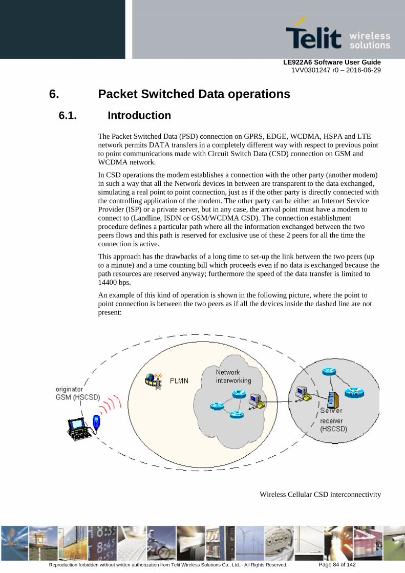
LE922A6 Software User Guide 1VV0301247 r0 – 2016-06-29
Reproduction forbidden without written authorization from Telit Wireless Solutions Co., Ltd..- All Rights Reserved. Page 84 of 142
6. Packet Switched Data operations
6.1. Introduction
The Packet Switched Data (PSD) connection on GPRS, EDGE, WCDMA, HSPA and LTE
network permits DATA transfers in a completely different way with respect to previous point
to point communications made with Circuit Switch Data (CSD) connection on GSM and
WCDMA network.
In CSD operations the modem establishes a connection with the other party (another modem)
in such a way that all the Network devices in between are transparent to the data exchanged,
simulating a real point to point connection, just as if the other party is directly connected with
the controlling application of the modem. The other party can be either an Internet Service
Provider (ISP) or a private server, but in any case, the arrival point must have a modem to
connect to (Landline, ISDN or GSM/WCDMA CSD). The connection establishment
procedure defines a particular path where all the information exchanged between the two
peers flows and this path is reserved for exclusive use of these 2 peers for all the time the
connection is active.
This approach has the drawbacks of a long time to set-up the link between the two peers (up
to a minute) and a time counting bill which proceeds even if no data is exchanged because the
path resources are reserved anyway; furthermore the speed of the data transfer is limited to
14400 bps.
An example of this kind of operation is shown in the following picture, where the point to
point connection is between the two peers as if all the devices inside the dashed line are not
present:
Wireless Cellular CSD interconnectivity

LE922A6 Software User Guide 1VV0301247 r0 – 2016-06-29
Reproduction forbidden without written authorization from Telit Wireless Solutions Co., Ltd..- All Rights Reserved. Page 85 of 142
CSD service is officially unavailable on this product but it is possible to enable the
CSD feature on 3G according to the requirement from a carrier.
It is required to discuss with chipset vendor, Qualcomm, to incorporate the CSD in this
product.
In PSD operations instead, the connection is made directly towards internet as if the PSD modem which
support GPRS/EDGE/WCDMA/HSPA/LTE was a network IP socket interface. There is no data path
reserved for the data exchange between the two peers, instead the resources are allocated dynamically
on demand and the data exchanged is organized into packets typically TCP/IP, furthermore the
maximum transfer speed can be much faster than GSM CSD.
An example of PSD connection is shown in the following picture, where the PSD connection
is between the PSD modem and the internet as if all the devices inside the dashed line are not
present:
Wireless Cellular PSD interconnectivity
Due to this kind of connection, when activating the PSD connection you must provide the
network parameters to enter through the internet point of the GPRS/EDGE/WCDMA/HSPA
/LTE network ISP (Internet Service Provider) and not the phone number to be dialed.
Therefore, it is not possible to establish a direct point-to-point PSD connection between two
modems as in CSD case. Instead an internet tunneling must be done to achieve a point to
point connection between two peers.
This approach as the immediate advantage of projecting the controlling application of the
PSD modem directly on the internet, ready to be accessed virtually from anywhere in the
world at the same cost on the GPRS/EDGE/WCDMA/HSPA/LTE network. Actually the
billing of the PSD connection is based on the amount of data exchanged (number of packets
transferred) independently from the time the connection is active or where these packets must
be delivered. Therefore, it is possible to leave the controlling application always connected
and ready to receive/send data on demand, while paying only for the data really exchanged.
The drawback of the PSD connection is that the controlling application must have its own
TCP/IP protocol stack embedded to decode the packets that arrive from
GPRS/EDGE/WCDMA/HSPA/LTE network and encode the ones to be sent through the
internet.
There are few considerations than must be done on the PSD connections:

LE922A6 Software User Guide 1VV0301247 r0 – 2016-06-29
Reproduction forbidden without written authorization from Telit Wireless Solutions Co., Ltd..- All Rights Reserved. Page 86 of 142
The WCDMA connection speed is symmetrical, 384kbps in reception and sending.
The DC-HSPA+ connection speed with release 9 device is asymmetrical, 42Mbps in
download and 11Mbps in upload.
The LTE connection speed with release 10 and cat 6 device is asymmetrical,
300Mbps in download and 50Mbps in upload.
The controlling application of the module must have a TCP/IP - PPP software stack to
interface with the PSD modems.
The controlling application must rely on some ISP that may be the Network Operator
of the SIM or USIM to gain access to the internet through the PSD connection.
Because of the dependency on ISP operator, the receiving application must have
internet access either.
Since the communication is based upon TCP/UDP/IP protocol, then it is possible to
talk contemporarily with more than one peer.
When required, the data security in internet must be guaranteed by security protocols
over the TCP/IP that must be managed by the controlling application.
6.2. Tethering Connection
This product supports 2 ways of tethering to have internet access from DTE.
6.2.1. Dial-Up Networking
It is legacy method to access internet service using public switched telephone network. The
DTE uses an attached modem to send and receive internet protocol packets. So, it is limited to
support high speed data rate over LTE technology. Not recommend to use this method for
internet access.
6.2.2. Standard ECM/RNDIS
ECM stands for Ethernet Control Model and is an Ethernet emulation protocol defined by the
USB Implementers Forum. RNDIS (Remote Network Driver Interface Specification) is a
Microsoft proprietary protocol used mostly on top of USB. It provides a virtual Ethernet link
to most versions of the Windows and Linux operating system.
To support LTE high speed data rate, this product provides CDC/ECM for USB interface
where DTE can be experienced high quality data service over LTE technology without any
limitation. ECM is used by many Linux distributions. It is recommended to use ECM /RNDIS
technology to experience LTE high speed date rate rather than dial up network.
Device acts as an Access Point which allows to connect to internet and has some features to
support connection to internet. Until now, it is only allowed to access internet service based
on USB tethering. Wi-Fi will be supported in the future.
- IPv4 NAT
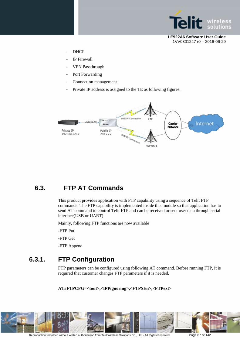
LE922A6 Software User Guide 1VV0301247 r0 – 2016-06-29
Reproduction forbidden without written authorization from Telit Wireless Solutions Co., Ltd..- All Rights Reserved. Page 87 of 142
- DHCP
- IP Firewall
- VPN Passthrough
- Port Forwarding
- Connection management
- Private IP address is assigned to the TE as following figures.
6.3. FTP AT Commands
This product provides application with FTP capability using a sequence of Telit FTP
commands. The FTP capability is implemented inside this module so that application has to
send AT command to control Telit FTP and can be received or sent user data through serial
interface(USB or UART)
Mainly, following FTP functions are now available
-FTP Put
-FTP Get
-FTP Append
6.3.1. FTP Configuration
FTP parameters can be configured using following AT command. Before running FTP, it is
required that customer changes FTP parameters if it is needed.
AT#FTPCFG=<tout>,<IPPignoring>,<FTPSEn>,<FTPext>

LE922A6 Software User Guide 1VV0301247 r0 – 2016-06-29
Reproduction forbidden without written authorization from Telit Wireless Solutions Co., Ltd..- All Rights Reserved. Page 88 of 142
Using this command, be able to configure following parameters
<tout> : Time-out to be required when opening either FTP control channel or traffic channel
<IPPignoring> : Determine if FTP client accepts private IP address assigned from server at
FTP passive mode or not.
<FTPSEn> : SSL security to FTP operation. Currently, all FTP commands use plain FTP
connection
<FTPext> : Select the extended FTP commands for ipv6 support(EPRT,EPSV) or not.
Default value is 0 (the extended FTP commands).
6.3.2. FTP Open and Close
To take advantage of FTP capability, it is required that FTP connection has to first of all be
opened to the server. Afterwards, FTP commands could be available on the connected FTP
channel.
AT#FTPOPEN=<server:port>,<username>,<password>,<mode>
<server:port> : Specify site of FTP server(IP address is also possible). If port is not added,
default FTP port(21) is used internally.
<username> : Effective FTP User ID
<password> : Effective FTP Password
<mode> : Specify FTP operation mode.
If it is failed to establish FTP connection within Time-out set by AT#FTPCFG, #FTPOPEN
command stops and return error message to DTE.
If FTP connection is no longer needed, it can be disconnected using below command
AT#FTPCLOSE
6.3.3. FTP Uploading file
Using this command, it is possible to upload a file to FTP server on the specified serial
interface mode. The serial interface mode is either online mode or command mode.
AT#FTPPUT=<filename>,<connMode>
<filename> : Specify file name to be created at FTP server
<connMode> : Select serial interface mode between module and DTE. Depending this mode,
the method how to upload a file is different.

LE922A6 Software User Guide 1VV0301247 r0 – 2016-06-29
Reproduction forbidden without written authorization from Telit Wireless Solutions Co., Ltd..- All Rights Reserved. Page 89 of 142
If <connMode> is specified “online mode”, user data can be entered on the serial port and
then those data are uploaded to FTP server. To complete FTP uploading, enter escape
sequence character set +++ and then FTP data connection is closed.
If <connMode> is specified “command mode”, user data can be uploaded using below
additional AT command. After running below command, enter the <bytestosend> size of
data on the serial port and then those data will be uploaded to FTP server
AT#FTPAPPEXT=<bytestosend>,<eof>
<bytestosend> : Specify number of bytes to be sent
<eof> : Determine if FTP uploading is to finish or not after completing to send the number of
data specified by <bytestosend> parameter.
If <eof> is 0(“normal sending of data chunk”), FTP connection for uploading triggered by
#FTPPUT command is maintained even if all <bytestosend> size of data are sent. In this
status, other FTP operation(like FTP get or append operation) could not work because FTP
put operation is in progress. To finish FTP put operation, refer to the case that <eof> is 1.
If <eof> is 1(“close data port after sending data chunk”), FTP connection for uploading is
finished once all <bytestosend> number of data are sent. Afterwards, other FTP operation is
now available.
It is possible to check if uploading file is done successfully by issuing #FTPLIST command.
It requests the list of contents of specified directory and properties of the specified file.
AT#FTPLIST=<name>
<name> : Name of directory or file.
If the <name> is not specified, content of current working directory is requested.
6.3.4. FTP Appending file
Using this command, can open FTP data connection and append data to existing file to the
FTP server.
AT#FTPAPP=<filename>,<connMode>
<filename> : Specify file name existing at FTP server
<connMode> : Select serial interface mode between module and DTE. Depending on this
mode, the method how to append a file is different.

LE922A6 Software User Guide 1VV0301247 r0 – 2016-06-29
Reproduction forbidden without written authorization from Telit Wireless Solutions Co., Ltd..- All Rights Reserved. Page 90 of 142
The module’s different behavior per <connMode> is same as the one of #FTPPUT command.
So, please refer to #FTPPUT command for more detail information how to use this command.
6.3.5. FTP Downloading file(Online Mode)
Using this command, can open FTP data connection, followed by downloading a specified
file from FTP server. The received data is transferred on the serial port which is operated at
online mode.
First of all, check if the file is existed in the FTP server or not
AT#FTPLIST=<name>
After checking the file through #FTPLIST command, run #FTPGET command.
AT#FTPGET=<filename>
<filename> : Specify existing file name at FTP server
6.3.6. FTP Downloading file in command mode
Using this command, can open FTP data connection and start downloading a file from FTP
server while serial interface is remained in command mode. Because this command triggers
FTP downloading in command mode, received data are buffered inside this module.
To retrieve the received data to application through serial interface, it is needed to run
additional AT command(AT#FTPRECV)
AT#FTPLIST=<name>
AT#FTPGETPKT=<filename>,<viewMode>
<filename> : Specify file name existing in the FTP server
<viewMode> : Determine the format of showing received data to application. If it is 0(text
format), module sends received data as plain text to application. It it is 1(hexadecimal format),
module sends received data as hexadecimal text to application
To check if file transfer is completed or not, query command is useful.
AT#FTPGETPKT?
#FTPGETPKT:<remotefile>,<viewMode>,<eof>

LE922A6 Software User Guide 1VV0301247 r0 – 2016-06-29
Reproduction forbidden without written authorization from Telit Wireless Solutions Co., Ltd..- All Rights Reserved. Page 91 of 142
<eof> : 0 means that file transfer is in progress, 1 means that file transfer is completed.
As mentioned above, following command can be used to retrieve received data in command
mode to application through serial port.
How many data is currently received from FTP server could be checked by following query
command
AT#FTPRECV?
#FTPRECV: 3000
It means that 3000 bytes are now available from module. If the response is not zero, run
following command
AT#FTPRECV=<blocksize>
<blocksize> : Max number of bytes to read from module(1 – 3000)
Once running this command, module is sent at most <blocksize> number of data to
application through serial port.
Repeat to run AT#FTPRECV? and AT#FTPRECV=<blocksize> commands until receiving
all data from FTP server.
AT#FTPGETPKT? query command is available to check if file transfer is completed
6.4. Email AT Commands
This product provides application with Email limited capability using a sequence of Telit
Email commands. The Email capability is implemented inside this module so that application
has to run AT command to control Telit Email function and send user data through serial
interface(USB or UART)
Mainly, following Email functions are now available
-Configuration
-Sending

LE922A6 Software User Guide 1VV0301247 r0 – 2016-06-29
Reproduction forbidden without written authorization from Telit Wireless Solutions Co., Ltd..- All Rights Reserved. Page 92 of 142
6.4.1. Email Configuration
It is required that customer configure this module with Email parameters prior to sending
email data using this product. Following is sequence of AT commands required in
configuring Email parameters
Configure SMTP server address used for Email sending
AT#ESMTP=<smtp>
<smtp> : It could be IP address type or host name to be solved with DNS
Configure a sender address to be seen as originator of this email
AT#EADDR=<e-addr>
<e-addr> : sender’s email address
Configure email user id authenticated by SMTP server
AT#EUSER=<e-user>
<e-user> : email User ID for authentication
Configure email password authenticated by SMTP server
AT#EPASSW=<e-pwd>
<e-pwd> : email password for authentication
If needed, save those parameters into the module permanently
AT#ESAV

LE922A6 Software User Guide 1VV0301247 r0 – 2016-06-29
Reproduction forbidden without written authorization from Telit Wireless Solutions Co., Ltd..- All Rights Reserved. Page 93 of 142
6.4.2. Sending Email(Without attachment)
With assumption of Email parameters configured and PDP cid 1 activated by #SGACT, it is
ready to send email to a specified receiver.
AT#EMAILD=<da>,<subj>
<da> : receiver email address
<subj> : subject of this email
The device responds to the command with the prompt '>' and waits for the message body text.
To complete the operation, send Ctrl-Z char (0x1A hex); to exit without writing the message,
send ESC char (0x1B hex)
6.4.3. Sending Email(With attachment)
It is possible to attach a file to email using #SMTPCL command. This command handles
attachment, managing MIME headers and encoding if required.
If attachment is not specified, command behavior is the same as #EMAILD.
Otherwise, the command works like #EMAILD regarding to message body text, then modem
goes into online mode(CONNECT indication is given) to allow the application to send the
attachment. Escape sequence has to be used to complete this command.
Encoding of data received on the serial port is performed if required.
AT#SMTPCL=<da>,<subj>,<att>,<filename>,<encod>
<da> : receiver email address
<subj> : subject of this email
<att> : file attachment. 0-no attachment, 1-text file, 2-binary file
<filename> : attached file name
<encod> : type of encoding the attachment. 0-7bit US-ASCII, 1-base 64
If txt file(<att>=1) is attached, only <encod> = 0 is possible
If binary file(<att>=2) is attached, only <encod>=1 is possible
6.5. HTTP AT Commands
This product provides application with HTTP capability using a sequence of Telit HTTP
commands. The HTTP capability is implemented inside this module so that application has to

LE922A6 Software User Guide 1VV0301247 r0 – 2016-06-29
Reproduction forbidden without written authorization from Telit Wireless Solutions Co., Ltd..- All Rights Reserved. Page 94 of 142
send AT command to control Telit HTTP and can be received or sent user data through serial
interface(USB or UART)
Mainly, following HTTP functions are now available
-HTTP Query
-HTTP Request
-HTTP Receive
6.5.1. HTTP Configuration
HTTP parameters should be configured with using the following AT command before
running HTTP operations.
AT#HTTPCFG=<prof_id>,<server_address>,<server_port>,<auth_type>,<username>,
<password>,<ssl_enable>,<timeout>,<cid>,<pkt_size>
Using this command, be able to configure following parameters
<prof_id> : The profile identifier
<server_address> : Indicating IP address of the HTTP server
<server_port> : Indicating the TCP remote port of the HTTP server
<auth_type> : The HTTP authentication type. 0 is for using authentication / 1 is for using
basic authentication
<username> : The user identification for using authentication
<password> : The authentication password
<ssl_enable> : SSL security for HTTP operation
<timeout> : The time interval to wait for receiving data from HTTP server.
<cid> : The PDP Context Identifier.
<pkt_size> : send(#HTTPSND) or recv(#HTTPRCV) size for data sending or receiving.
6.5.2. HTTP Query
Using the following command, it is possible to send a HTTP GET, HEAD or DELETE
operation to HTTP server.
AT#HTTPQRY=<prof_id>,<command>,<resource>,<extra_header_line>
<prof_id> : The profile identifier.

LE922A6 Software User Guide 1VV0301247 r0 – 2016-06-29
Reproduction forbidden without written authorization from Telit Wireless Solutions Co., Ltd..- All Rights Reserved. Page 95 of 142
<command> : Indicating the command requested to HTTP server. 0 is for HTTP GET / 1 is
for HTTP HEAD / 2 is for HTTP DELETE.
<resource> : Indicating the HTTP resource(URI).
<extra_header_line> : String parameter to be included within the optional HTTP header line.
If sending ends successfully, the response is OK, otherwise an error code is reported.
When the HTTP server answer is received, this product sent the following URC through serial
interface(USB or UART)
#HTTPRING:<prof_id>,<http_status_code>,<content_type>,<data_size>
<prof_id> : The profile identifier that is defined above.
<http_status_code> : The numeric status code received from the server(refer to RFC2616).
<content_type> : The string is in the "Content-Type" header line from the server(refer to
RFC2616).
<data_size> : The byte amount of the requested content received from the server. if server
does not report size in the "Content-Length:" header line, this parameter value is 0.
6.5.3. HTTP Request
Using the following command, it is possible to send a HTTP POST or PUT operation to
HTTP server.
AT#HTTPSND=<prof_id>,<command>,<resource>,<data_len>,<post_param>,<extra_
header_line>
<prof_id> : The profile identifier.
<command> : Indicating the command requested to HTTP server. 0 is for HTTP POST / 1 is
for HTTP PUT.
<resource> : Indicating the HTTP resource(URI).
<data_len> : Indicating the data length to input in bytes.
<post_param> : Indicating the HTTP Content-Type identifier used only for POST command.
<extra_header_line> : String parameter to be included within the optional HTTP header line.
The format of <post_param> is "Numeric[:extension]". the module supports 4 content types.
"0[:extension]" - "application/x-www-form-urlencoded" with optional extension.

LE922A6 Software User Guide 1VV0301247 r0 – 2016-06-29
Reproduction forbidden without written authorization from Telit Wireless Solutions Co., Ltd..- All Rights Reserved. Page 96 of 142
"1[:extension]" - "text/plain" with optional extension.
"2[:extension]" - "application/octet-stream" with optional extension.
"3[:extension]" - "application/form-data" with optional extension.
For example, if <post_param> is "1:charset=UTF-8", the module converts "1" to "text/plain"
and also converts ":charset=UTF-8" to "; charset=UTF-8".
So the module adds "text/plain; charset=UTF-8" into the Content-Type of HTTP Header.
If sending ends successfully, the response is OK, otherwise an error code is reported.
When the HTTP server answer is received, the module sent the URC(refer to #HTTPRING
URC in 6.4.2).
Note : When using the AT#HTTPSND command, the HTTP header always include
"Connection: close" line and it can not be removed.
6.5.4. HTTP Receive
When notified #HTTPRING URC, it is possible to read data from HTTP server to use the
AT#HTTPRCV command.
AT#HTTPRCV=<prof_id>,<maxByte>
<prof_id> : The profile identifier.
<maxByte> : Max number of bytes to read at once. Range is 0, 300-1500(default is 0 which
means infinite size).
Note : If the data are not present or the #HTTPRING <http_status_code> parameter has value
0, an error code is reported.
6.6. IP Easy Extension – Multisocket AT Commands
6.6.1. Overview
The IP Easy feature allows the Telit module users to contact a device on internet and
establish with it a raw data flow over the UMTS/HSPA/LTE and Internet networks.
This feature can be seen as a way to obtain a "virtual" serial connection between the
Application Software on the Internet machine involved and the controller of the Telit
module, regardless of all the software stacks underlying.
An example of the protocol stack involved in the devices is reported:

LE922A6 Software User Guide 1VV0301247 r0 – 2016-06-29
Reproduction forbidden without written authorization from Telit Wireless Solutions Co., Ltd..- All Rights Reserved. Page 97 of 142
This specific implementation allows the devices to interface to the Telit module via
UMTS/HSPA/LTE and Internet packets without the need of an internal TCP/IP stack since
this function is already embedded inside the module.
As a new functionality of Telit modules, multisocket is an extension of the Telit IP Easy
feature, which allows the user to have more than 1 activated PDP context (this means multiple
different IP address), more than one socket connection -- with a maximum of 6 connections --
and simultaneous FTP client and EMAIL client services.
The basic idea behind multisocket is the possibility of suspending an active socket connection
with the escape sequence +++ and resuming the connection if needed.
With the #SKTD command it is possible to open a socket connection and get online. When
the online activities are fulfilled, the +++ sequence is used to close the connection (see the
figure below).
The green part represents the module command mode while the red part is the online mode.

LE922A6 Software User Guide 1VV0301247 r0 – 2016-06-29
Reproduction forbidden without written authorization from Telit Wireless Solutions Co., Ltd..- All Rights Reserved. Page 98 of 142
Now, the online mode can be suspended with the escape sequence +++ under the multisocket
feature. During suspend mode the data received by the socket will be buffered, which data
will be displayed after socket resumption, as shown in the figure below:
This new feature allows users to switch between online mode and command mode without
closing the connection or even opening another socket (or resuming the suspended one), FTP
or EMAIL connection.
Another new feature is the possibility to associate any socket connection to a specific context.
This means that we can use different IP addresses per each PDP connection. The Socket
Identifier is called Connection Id -- selects which socket we want to use from 1 up to 6 -- and
every Connection Id is associated to a PDP context.
6.6.2. Commands Overview What follows are new AT command sequences that activate context, sets and opens the socket
connection. There will be explained a new listen command and how to use FTP and Easy
GPRS at the same time.
NOTE:
For more detailed AT commands and parameters definitions please consult the AT
Commands Reference Guides.
6.6.2.1. IP Easy Outgoing Connection The IP Easy feature provides a way to place outgoing TCP/UDP connections and keep the
same IP address after a connection is made, leaving the context active.
The steps required to open a socket and close it without closing the PDP context are:
configuring the UMTS/HSPA/LTE Access
configuring the embedded TCP/IP stack behavior
defining the Internet Peer to be contacted

LE922A6 Software User Guide 1VV0301247 r0 – 2016-06-29
Reproduction forbidden without written authorization from Telit Wireless Solutions Co., Ltd..- All Rights Reserved. Page 99 of 142
request the context to be activated
request the socket connection to be opened
exchange data
close the TCP connection while keeping the context active
All these steps are achieved through AT commands. As far as the common modem interface,
two logical statuses are involved: command mode and data traffic mode.
In Command Mode (CM), some AT commands are provided to configure the Data
Module Internet stack and to start up the data traffic.
In data traffic mode (Socket Mode, SKTM), the client can send/receive a raw data
stream which will be encapsulated in the previously configured TCP / IP packets
which will be sent to the other side of the network and vice versa. Control plane of
ongoing socket connection is deployed internally to the module.
6.6.2.1.1. Configuring the UMTS/HSPA/LTE access
The access configuration is done by setting:
the number of PDP context parameter (see +CGDCONT command)
the Authentication parameters: User Name and Password (see command #SGACT)
6.6.2.1.2. Configuring the embedded TCP/IP stack
The TCP/IP stack behavior must be configured by setting:
the packet default size
the data sending timeout
the socket inactivity timeout
Before opening a connection we have to set the socket parameters with the new #SCFG
command. It is possible to set all the timeout values and packet size for each socket
connection with a single AT command. The command syntax is:
AT#SCFG = <Conn Id>, <Cntx Id>, <Pkt sz>, <Max To>, <Conn To>, <Tx To>
Where:
Conn Id - the connection identifier

LE922A6 Software User Guide 1VV0301247 r0 – 2016-06-29
Reproduction forbidden without written authorization from Telit Wireless Solutions Co., Ltd..- All Rights Reserved. Page 100 of 142
Cntx Id - the context identifier
Pkt sz - the minimum data packet sent to the net (default 300 bytes)
Max To - inactivity timeout (default 90 sec.)
Conn To - connection timeout (default 60 sec, expressed in tenths of second)
Tx To - data sending timeout (default 5 sec, expressed in tenths of second)
The first two parameters are new and they represent the association between the socket
connection and the context set with +CGDCONT. It means that we can have socket
connection working on different IP addresses.
The other parameters replace the old IP Easy commands #DSTO, #SKTTO, #SKTCT and
#PKTSZ.
If we try to modify the socket configuration of an online connection, an error will appear. So
it’s recommended to set the socket configuration at the beginning. It is strongly recommended
to leave the first Connection Id associated to context one to allow simultaneous FTP, SMTP
and IP Easy services.
The values set with this command are saved in NVM.
Example:
We want to associate the Connection Id number 2 to the context number 3 with a minimum
packet size of 512 bytes, max timeout of 30 sec, connection timeout of 30 sec and
transmission timeout of 10 sec.
Command:
AT#SCFG = 2, 3, 512, 30, 300,100
Answer:
OK if command execution is correct
ERROR if a parameter is wrong or the connection Id is working online
6.6.2.1.3. Request the context to be activated
This command allows activation of one of the contexts defined with AT command
+CGDCONT. With multisocket it is possible to activate simultaneously two contexts of the

LE922A6 Software User Guide 1VV0301247 r0 – 2016-06-29
Reproduction forbidden without written authorization from Telit Wireless Solutions Co., Ltd..- All Rights Reserved. Page 101 of 142
five that have been set. We can write username and password directly from command line (if
required). At least one Connection Id must be associated to the context we want to activate;
otherwise an error will be appear.
The command syntax is:
#SGACT= <Cntx Id>,<Status>, [<Username>],[<Password>]
Where:
Cntx Id is the context that we want to activate/deactivate.
Status is the context status (0 means deactivation, 1 activation).
Example:
We want to activate context number two defined with +CGDCONT.
Command:
AT#SGACT = 2,1
Answer:
#SGACT: “212.195.45.65”
OK if activation success.
ERROR if activation fails.
The response code to the AT#SGACT=1 command reports the IP address obtained from the
network, allowing the user to report it to his server or application.
Deactivating the context implies freeing the network resources previously allocated to the
device.
NOTE:
Also the command AT+CGACT activates a context, but in this case the context cannot be
used for IP Easy.
In LTE network, the default PDP context is activated by piggybacking on LTE attach
procedure and maintained until detached from NW. This command is just binding or
unbinding application to the default PDP context.
It’s also possible to set authentication type through the command AT#SGACTAUTH.
The command syntax is:
LE922A6 Software User Guide 1VV0301247 r0 – 2016-06-29
Reproduction forbidden without written authorization from Telit Wireless Solutions Co., Ltd..- All Rights Reserved. Page 102 of 142
AT#SGACTAUTH=<type>
0 – no authentication
1 – PAP authentication(factory default)
2 - CHAP authentication
It’s also possible to enable automatic activation/reactivation of a specified PDP context in
case of switching off/on, in case of deactivation from Network and in case of SIM/UICC
removal.
NOTE: at least one IPEasy socket has to be previously associated to this context by command
AT#SCFG. The command syntax is:
AT#SGACTCFG=<Cntx Id>,<retry>[,<delay>[,<urcmode>]]
Where:
<Cntx Id>(1-5) is the context that we want to automatic activate/reactivate
<retry>(0-15) is the number of activation/reactivation attempts(if it fails)
<delay>(180-3600) is the delay(sec) between two successive attempts
<urcmode>(0-1) enable unsolicited result code of the local IP address obtained from
the network
Example:
AT#SGACTCFG=1,3 activation/reactivation set on context 1 with 3 attempts.
No previous setting through #SCFG is needed in this case, because socket connection
identifiers <Conn Id> 1,2,3 are already associated to <Cntx Id> 1 by default.
Furthermore it is possible to abort a context activation attempt, while waiting for AT response,
by sending a char on the serial port.
To enable this feature on a <cid> new #SGACTCFGEXT command has been implemented.
The command syntax is:
AT#SGACTCFGEXT=<cid>,<abortAttemptEnable>
By setting <abortAttemptEnable> on <cid>, attempt pre-emption
is allowed.
For more details, please refer to refer to the AT Commands Reference Guide.
6.6.2.1.4. Open the connection with the internet host
With the AT command #SD (socket Dial) the TCP/UDP request to connect with the internet
host starts:
DNS query is done to resolve the IP address of the host name internet peer if required

LE922A6 Software User Guide 1VV0301247 r0 – 2016-06-29
Reproduction forbidden without written authorization from Telit Wireless Solutions Co., Ltd..- All Rights Reserved. Page 103 of 142
Telit module establishes a TCP/UDP (depending on the parameter request)
connection with the given internet host
Once the connection is up the module reports the code: CONNECT
The command syntax is:
AT#SD = <Conn Id>,<Protocol>, <Remote Port>, <IP address> [, <Closure Type> [,
<Local Port>,[<connMode>,[<userIpType>]]]]
Where:
Conn Id is the connection identifier.
Protocol is 0 for TCP and 1 for UDP.
Remote Port is the port of the remote machine.
IP address is the remote address.
To open the remote connection the context to which the Connection Id is associated must be
active, otherwise an error will appear.
For example, if we want to connect to a web server with Connection Id number 3 the
command is:
AT#SD=3,0,80,“www.telit.com”
If the command is successful we’ll have a CONNECT message, and the socket number 3 will
be connected to the Telit webserver.
From this moment the data incoming in the serial port is packet and sent to the Internet host,
while the data received from the host is serialised and flushed to the Terminal Equipment.
The +++ sequence does not close the socket, but only suspends it.
NOTE:
Check guard time/S12 parameter before and after escape sequence.
We can suspend the connection and open another one with a different Connection Id.
A typical command sequence is:
AT#SD = 3 ,0 ,80 ,“www.telit.com”
CONNECT
(send, receive data….)

LE922A6 Software User Guide 1VV0301247 r0 – 2016-06-29
Reproduction forbidden without written authorization from Telit Wireless Solutions Co., Ltd..- All Rights Reserved. Page 104 of 142
(+++)
OK
OK is returned after the escape sequence, it means that the socket has been suspended
correctly.
Now the connection number 3 is suspended and the module is in command mode so we can
give another #SD command.
AT#SD = 2 ,0,80,“www.google.com”
CONNECT
(send, receive data….)
(+++)
OK
If we try to open a connection while the ConnId is in suspended state or online an error will
be occur.
If a suspended connection receives some data the user will receive an unsolicited SRING
indication from the module. In case we receive some data from the suspended connection
with Telit server we’ll receive this unsolicited message:
SRING: 3
where 3 is the number of the ConnId with data pending.
NOTE:
The unsolicited SRING indication appears only in command mode.
6.6.2.1.5. Resuming a suspended connection with #SO
This is the new command to resume a suspended connection, the command syntax is:
AT#SO = <Conn Id>
Example:
AT#SD=2,0,80,“www.google.com”
CONNECT
data sending
(+++)
OK

LE922A6 Software User Guide 1VV0301247 r0 – 2016-06-29
Reproduction forbidden without written authorization from Telit Wireless Solutions Co., Ltd..- All Rights Reserved. Page 105 of 142
SRING: 2
AT#SO=2
CONNECT
data sending
(+++)
In case there is data pending on this socket -- you can know this the unsolicited message
SRING has appeared before--, issuing command AT#SO these pending data will be displayed
after the CONNECT string.
It is possible to resume a suspended socket without waiting for SRING message or data
pending on that connection.
Using AT#SO on a Connection Id in idle state (no socket open or suspended) we obtain a NO
CARRIER message.
6.6.2.1.6. Close the Socket without deactivating the context
The connection can be closed for the following reasons:
remote host TCP connection close
socket inactivity timeout
Terminal Equipment by issuing the escape sequence "+++" and AT#SH that specifies
the Connection Id
Network deactivation
It is possible to get socket disconnection cause with AT command AT#SLASTCLOSURE.
The AT command syntax to use is:
AT#SLASTCLOSURE=[<connId>]
The response format is:
#SLASTCLOSURE: <connId>,<cause>
For details, please consult the AT Commands Reference Guides. With the new management
of the escape sequence we need a command to close the socket connection. The AT command
syntax to use is:
AT#SH=<conn Id>
Example:

LE922A6 Software User Guide 1VV0301247 r0 – 2016-06-29
Reproduction forbidden without written authorization from Telit Wireless Solutions Co., Ltd..- All Rights Reserved. Page 106 of 142
AT#SD=2,0,80,“www.google.com”
CONNECT
data sending
(+++)
OK
AT#SH=2
OK
Now the connection is closed. If we send this command with an idle Connection Id we obtain
in any case an OK message.
NOTE:
If there is an escape sequence in the raw data to be sent, then the TE must work it out and sent
it in a different fashion to guarantee that the connection is not closed.
The pause time is defined in the parameter S12. To avoid sending of the escape sequence a
command AT#SKIPESC should be set at the beginning.
6.6.2.1.7. Sending and receiving base64 encoded data
Through new #BASE64 command is possible to enable base64 encoding/decoding of data
sent/received on a socket.
The command syntax is: AT#BASE64=<connId>,<enc>,<dec> where <enc> and <dec>
enable respectively encoding and/or decoding on <connId> socket.
<enc> and <dec> can be set to 1 or 2 depending on MIME line feeds setting required (please
refer to the AT Commands Reference Guides)
Encoding: if enabled, all data are encoded base64 while they are received from serial port,
before to be sent on <connId> socket.
Decoding: if enabled, all data are decoded base64 while they are received from <connId>
socket, before to be sent on the serial port.
Example:
AT#SKIPESC=1
OK
AT#SD=1,0,<port>,"IP"
CONNECT

LE922A6 Software User Guide 1VV0301247 r0 – 2016-06-29
Reproduction forbidden without written authorization from Telit Wireless Solutions Co., Ltd..- All Rights Reserved. Page 107 of 142
Data received from serial port are sent directly on the socket
+++ (suspension)
AT#BASE64=1,1,0
OK
AT#SO=1
CONNECT
Data received from serial port are encoded
base64 before to be sent on the socket
+++ (suspension)
AT#BASE64=1,0,1
OK
AT#SO=1
CONNECT
Data received from socket are decoded base64 before to be sent on the serial port
+++ (suspension)
NOTE:
It is also possible to use new feature in command mode (Please refer to AT Commands
Reference Guides).
6.6.2.2. IP Easy Incoming Connection The IP Easy feature provides a way to accept incoming TCP/UDP connections and keep the
same IP address after a connection, leaving the context active.
The steps that will be required to open a socket in listen, waiting for connection requests from
remote hosts and accept these request connections only from a selected set of hosts, then close
it without closing the context are:
configuring the GPRS/UMTS/HSPA/LTE Access
configuring the embedded TCP/IP stack behavior (see par.6.7.2.1.2)
defining the Internet Peer that can contact this device (firewall settings) (see
par.6.7.2.2.1)
request the context to be activated (see par.6.7.2.1.3)

LE922A6 Software User Guide 1VV0301247 r0 – 2016-06-29
Reproduction forbidden without written authorization from Telit Wireless Solutions Co., Ltd..- All Rights Reserved. Page 108 of 142
request the socket connection to be opened in listen (see par. 6.7.2.2.2)
receive connection requests (see par.6.7.2.2.3)
exchange data
close the TCP connection while keeping the context active (see par.6.7.2.1.6)
All these steps are achieved through AT commands. As for common modem interface, two
logical statuses are involved: command mode and data traffic mode.
In Command Mode (CM), some AT commands are provided to configure the Data
Module Internet stack and to start up the data traffic.
In data traffic mode (Socket Mode, SKTM), the client can send/receive a raw data stream
which will be encapsulated in the previously configured TCP / IP packets which will be sent
to the other side of the network and vice versa. Control plane of ongoing socket connection is
deployed internally to the module.
6.6.2.2.1. Defining the Internet Peer that can contact this device (firewall settings)
The Telit module has an internal Firewall that controls the behavior of the incoming
connections to the module. The firewall applies for INCOMING (listening) connections;
OUTGOING connections will be always done regardless of the firewall settings.
Firewall General policy is DROP, therefore all packets that are not included into an ACCEPT
chain rule will be silently discarded.
When packet incomes from the IP address <incoming IP>, the firewall chain rules will be
scanned for matching with the following criteria:
<incoming IP> & <net mask> = <ip_address> ?
if the result is yes, then the packet is accepted and the rule scan is finished, otherwise the next
chain is taken into account until the end of the rules when the packet is silently dropped if no
matching was found.
For example, let’s assume we want to accept connections only from our devices which are on
the IP addresses ranging from 197.158.1.1 to 197.158.255.255
We need to add the following chain to the firewall:
AT#FRWL=1,"197.158.1.1","255.255.0.0"
6.6.2.2.2. Request the socket connection to be opened in listen
The new listen command is now extended to 6 connections; it’s possible to set from 1 to 6
socket listening on a specific port for the incoming connections. Another difference with the

LE922A6 Software User Guide 1VV0301247 r0 – 2016-06-29
Reproduction forbidden without written authorization from Telit Wireless Solutions Co., Ltd..- All Rights Reserved. Page 109 of 142
old IP Easy is that now we receive an unsolicited indication when someone tries to connect,
so we can decide to accept (AT#SA) or refuse (AT#SH) the incoming connection.
NOTE:
In case you decide to reject an incoming connection request the listening socket will be closed
and if you want to re-open it the AT command AT#SL needs to be re-issued.
The command syntax is:
AT#SL = <Conn Id>, <Listen state>, <Listen port>[, <Closure Type>]
It’s not possible to have two ConnId listening on the same port.
Example:
Suppose that we want to listen on port 6543 Connection Id number 2
AT#SL = 2, 1, 6543
OK
Now the module is listening for incoming connection on port 6543 with Connection Id
number 2, if a remote host is trying to connect we’ll receive a SRING unsolicited indication
with the listening Connection Id:
SRING: 2
6.6.2.2.3. Accept an incoming connection with #SA
After receiving the SRING indication for an incoming connection we can decide to refuse the
remote host connection with #SH command or accept the connection with #SA command.
The command syntax is:
AT#SA = <conn Id>
Example:
We are listening on Connection Id 3 and port 6543
AT#SL = 3, 1, 6543
OK
A remote host is trying to connect, we receive the unsolicited indication.
SRING: 3
LE922A6 Software User Guide 1VV0301247 r0 – 2016-06-29
Reproduction forbidden without written authorization from Telit Wireless Solutions Co., Ltd..- All Rights Reserved. Page 110 of 142
Now we accept the connection
AT#SA = 3
CONNECT
We pass in online mode and the connection is established. With the escape sequence we
suspend the socket and the module is back to command mode. To resume the suspended
connection we can use the #SO command described above.
NOTE:
It’s also possible to accept automatically the incoming connection if the <ListenAutoRsp>
parameter has been set through the command AT#SCFGEXT(for the specific connId);
see also par. 6.7.3.2.2.
In this case no unsolicited indication is received, but the connection is automatically accepted:
the CONNECT indication is given and the modem goes into online data mode.
It’s also possible to open a socket listening for an incoming UDP connection on a specified
port.
The command syntax is:
AT#SLUDP=<connId>, <listenState>, <listenPort>
Also in this case it’s possible to receive SRING unsolicited and decide to accept (AT#SA) or
refuse (AT#SH).
It is also possible to accept automatically incoming connection depending on
<ListenAutoRsp> settings.
6.6.2.2.4. Checking the socket status with #SS
With the old IP Easy socket connection the possible states were: online state or closed, while
with multi-socket suspension we have other socket states. With the new command AT#SS we
can see the status of all the six sockets.
The command syntax is:
AT#SS
[=<connId>]
Suppose that we have suspended some sockets and we are in command mode, in order to
verify which Connection Id has been opened, we can use AT#SS command to have a snapshot
of sockets status.

LE922A6 Software User Guide 1VV0301247 r0 – 2016-06-29
Reproduction forbidden without written authorization from Telit Wireless Solutions Co., Ltd..- All Rights Reserved. Page 111 of 142
The command result is:
#SS: <ConnId>,<Status>,<Local IP>,<Local Port>,<Remote IP>,<Remote Port>
For every Connection Id with have the information about our local IP address, local port,
remote IP and port if we are connected.
The Status field represents the socket status:
0 – Socket Closed.
1 – Socket with an active data transfer connection.
2 – Socket suspended.
3 – Socket suspended with pending data.
4 – Socket listening.
5 – Socket with an incoming connection. Waiting for the user accept or shutdown
command.
6 - Socket in opening process. The socket is not in closed state but still not in Active or
Suspended or Suspended with pending data state.
Example:
AT#SS
#SS: 1,4,217.201.131.110,21
#SS: 2,2,217.201.131.110,1033,194.185.15.73,10510
#SS: 3,3,217.201.131.110,1034,194.185.15.73,10510
#SS: 4,1,217.201.131.110,1035,194.185.15.73,10510
#SS: 5,0
#SS: 6,0
OK
In this case we can see Connection Id 1 in listen mode on port 21, number 2 suspended with
no data pending, number 3 suspended with pending data and number 1 is online. The last two
connections are closed
By issuing AT#SS=<connId> it’s possible to get status only of the corresponding socket.
6.6.3. Command Mode Connections

LE922A6 Software User Guide 1VV0301247 r0 – 2016-06-29
Reproduction forbidden without written authorization from Telit Wireless Solutions Co., Ltd..- All Rights Reserved. Page 112 of 142
6.6.3.1. Overview
6.6.4. This feature allows Telit’s modules to establish a socket connection in command mode. The “classic” online mode connection is described in the figure below:
With command mode feature now we have:
This means that the socket connection is created, but the user can give AT commands as
usually in command mode. If we receive some data on a socket a SRING message is raised.
6.6.4.1. Commands Overview This paragraph describes the configuration and the activation of a command mode connection
and the AT commands implemented to use the new configuration socket parameters.
For anything concerning outgoing and incoming connections, you can refer to the chapter
“Enhanced IP Easy Extension“: there are no differences at sockets level.
NOTE:
For more detailed AT commands and parameters definitions consult the AT Commands
Reference Guide.
6.6.4.1.1. Opening a socket connection in command mode

LE922A6 Software User Guide 1VV0301247 r0 – 2016-06-29
Reproduction forbidden without written authorization from Telit Wireless Solutions Co., Ltd..- All Rights Reserved. Page 113 of 142
To open a socket in command mode we must use the multisocket commands AT#SD or
AT#SA.
After a PDP context activation with AT#SGACT it is possible to open all sockets associated
to this PDP context in command mode using:
AT#SD=<connId>,<txProt>,<rPort>,<IPaddr>[,<closure type>[,<lPort>],1,[< userIpType>]]]
In case of listening, after an unsolicited indication for an incoming connection
SRING: <connId>
we have to use:
AT#SA = <connId>,1
where the last parameter of AT#SD and AT#SA is <ConnMode>. Default value is 0 which
means “classic” online mode, 1 is used for command mode.
Examples:
Open a command mode socket on connection Id number 1: AT#SD =1,0,10510,”88.37.127.146”,0,0,1
OK
After an unsolicited indication for an incoming connection on a listening connId: SRING: 1
AT#SA = 1,1
OK
In “classic” online mode, if the connection is successful we have a CONNECT message, in
this case we have only an OK message in case of success and we are still in command mode.
To check if the connection is really established we ca use the AT#SS command to control
socket status.
AT#SS
#SS: 1,2,217.202.12.22,38158,88.37.127.146,10510
#SS: 2,0
#SS: 3,0
#SS: 4,0
#SS: 5,0
#SS: 6,0
We can see that connection Id 1 is opened in suspended state.
6.6.4.1.2. Configuring extended socket parameters
Before opening socket connections it is possible to set extended configuration parameters on
each of six sockets available with multisocket.

LE922A6 Software User Guide 1VV0301247 r0 – 2016-06-29
Reproduction forbidden without written authorization from Telit Wireless Solutions Co., Ltd..- All Rights Reserved. Page 114 of 142
The main feature regards SRING unsolicited messages. These messages inform the user that
there are pending data on a specific connection Id.
We have three modes:
Classic SRING: only one message (SRING: <connId> ) when some new data arrive
on a socket connection ( like it was for a socket connection of multisocket). This
message is received also when there’s an incoming connection on listening
connection Id.
Data amount SRING: an unsolicited message is raised for every new packet received
on a socket connection. The message gives information on the connection id and on
the number of bytes pending in the socket buffer.
View data SRING: in this message we have connection Id, amount of buffered data by
the socket and a string (up to 1300 chars for HE910 product family, up to 64 chars for
all other products) with the dump of data extracted from the socket buffer. An
unsolicited is raised until the socket buffer is empty. In this specific case we can
decide to see data as text or as hex using the <recvDataMode> parameter (default
value is 0 – text).
View data UDP SRING: the message is the same as the previous one for TCP
connections, but for UDP connections it shows also the source IP and port and the
number of bytes left in the datagram.
NOTE:
The data amount is updated until the maximum TCP windows size for reception is reached.
The command syntax is:
AT#SCFGEXT = <connId>,<srMode>,<recvDataMode>,<keepalive>
[,<ListenAutoRsp> [,<sendDataMode>] ]
Where:
<connId> is the connection identifier.
<srMode> is the unsolicited Sring mode.
<recvDataMode> sets text or hex data view for received data in command mode
<KeepAlive> sets TCP keepalive parameter in minutes (up to 240), 0 means
keepalive disabled.
<ListenAutoRsp> Set the listen auto-response mode, that affects the commands
AT#SL and AT#SLUDP
<sendDataMode> sets text or hex data mode for sending data in command
mode(AT#SSEND)

LE922A6 Software User Guide 1VV0301247 r0 – 2016-06-29
Reproduction forbidden without written authorization from Telit Wireless Solutions Co., Ltd..- All Rights Reserved. Page 115 of 142
Examples:
AT#SCFGEXT = 1,1,0,0 - Socket 1 set with SRING data amount
AT#SCFGEXT = 1,2,1,0 - Socket 1 set with SRING view data mode in hex.
AT#SCFGEXT = 1,2,1,0,0,1 – Socket 1 set also with hex data mode for sending data
AT#SCFGEXT = 1,3,1,0 - Socket 1 set with SRING view UDP data mode in hex.
NOTE:
With AT command #SCFGEXT2 is possible to set other configuration parameters.
The command syntax is:
AT#SCFGEXT2 = <connId>,<bufferStart>,[,<abortConnAttempt> [,<unused_B
>[,<unused_C >[,<unused_D>]]]]
Where:
<connId> is the connection identifier of the socket on
which settings take effect
<bufferStart> sets new behavior for data sending timer
(which timeout <Tx To> is set through #SCFG):
restart every time new bytes are received from the
serial port.
Note: when enabled, old behavior for data sending timer
is automatically disabled to avoid overlapping.
<abortConnAttempt> enables connection attempt abort
(#SD/#SKTD/#SKTOP) before CONNECT(online mode) or
OK(command mode).
It is possible to abort attempt and give back control to
AT interface by pressing any key.
As soon as the control has been given to the AT interface
the ERROR message will be received on the interface itself.
To get more details on which settings are available on
different chipsets, please consult the AT Commands Reference Guide.
LE922A6 Software User Guide 1VV0301247 r0 – 2016-06-29
Reproduction forbidden without written authorization from Telit Wireless Solutions Co., Ltd..- All Rights Reserved. Page 116 of 142
6.6.4.1.3. Send data in command mode connections
To send data in command mode we can use the command AT#SSEND.
At the prompt we can write data and send immediately on the socket with CTRL-Z sequence.
Maximum number of bytes is 1500, if more characters are written they are truncated in upload.
The command syntax is:
AT#SSEND = <connId>
Where <connId> is the connection Id of the socket that we want to use to send data (socket
must be opened otherwise an error is raised).
Example:
We send the string “hello” on an echo socket with SRING mode set to Data amount.
AT#SSEND=1
> hello<CTRL-Z>
OK
SRING: 1,5
NOTE:
Through new AT#SSENDEXT command it is possible to include all bytes within data to
send, including special characters(ESC, Ctrl-Z and BS) previously reserved with #SSEND.
The command syntax is:
AT#SSENDEXT = <connId>,<bytestosend>
When <bytestosend> bytes have been sent to the serial port, operation is automatically
completed.
6.6.4.1.4. Receive data in command mode connections
To receive data in command mode it is possible to use the AT#SRECV.
If we receive an unsolicited message SRING we can extract the data from the socket buffer in
command mode. The syntax of the command is:
AT#SRECV=<connId>,<maxByte>
Where :
<connId> is the connection Id of the socket with data pending
<maxbytes> is the number of pending bytes we want to extract (maximum value is
1500).
LE922A6 Software User Guide 1VV0301247 r0 – 2016-06-29
Reproduction forbidden without written authorization from Telit Wireless Solutions Co., Ltd..- All Rights Reserved. Page 117 of 142
Example:
We receive a SRING data amount and then we extract all the five bytes pending with SRECV.
SRING: 1,5
at#srecv=1,5
#SRECV: 1,5
hello
OK
6.6.4.1.5. Socket Information command
It is possible to have additional information on every socket with the AT#SI command.
The command syntax is:
AT#SI [= <connId>]
Where connId is an optional parameter, we can see info on a specific socket or for all sockets.
The information shown by the command are:
Data sent on the socket.
Data extracted from the socket buffer.
Data pending on the socket buffer.
Data not acknowledged by the remote.
AT#SI
#SI: 1,123,400,10,50
#SI: 2,0,100,0,0
#SI: 3,589,100,10,100
#SI: 4,0,0,0,0
#SI: 5,0,0,0,0
#SI: 6,0,98,60,0
OK
Sockets 1,2,3,6 are opened with some data traffic.
For example socket 1 has 123 bytes sent, 400 bytes received, 10 byte waiting to be
read and 50 bytes waiting to be acknowledged from the remote side.
6.6.4.2. Examples
6.6.4.2.1. Open a command mode connection with Classic SRING
LE922A6 Software User Guide 1VV0301247 r0 – 2016-06-29
Reproduction forbidden without written authorization from Telit Wireless Solutions Co., Ltd..- All Rights Reserved. Page 118 of 142
Open a connection on an Echo port:
AT#SD=2,0,10510,”88.37.127.146”,0,0,1
OK
AT#SSEND=2
> hello
OK
SRING: 2
AT#SSEND=2
> hello
OK
…
Only one SRING unsolicited also if we have other data pending, the user is informed only
once.
6.6.4.2.2. Open a command mode connection with Data amount SRING
Open a connection on an Echo port:
AT#SD=2,0,10510,”88.37.127.146”,0,0,1
OK
AT#SSEND=2
> hello
OK
SRING: 2,5
AT#SSEND=2
> hello
OK
SRING: 2,10
SRING data amount unsolicited is updated every time new data arrives on the socket.
Now we use AT#SI to see info on connection Id 2:
AT#SI=2
#SI: 2,10,0,10,0
Ten bytes sent and ten pending on the socket.
6.6.4.2.3. Open a command mode connection with Data view SRING
We configure connection Id 1 for data view in text mode:
AT#SCFGEXT = 1,2,0,0
OK

LE922A6 Software User Guide 1VV0301247 r0 – 2016-06-29
Reproduction forbidden without written authorization from Telit Wireless Solutions Co., Ltd..- All Rights Reserved. Page 119 of 142
We configure connection Id 2 for data view in hex mode for received data:
AT#SCFGEXT = 2,2,1,0
OK
Open the two echo connections in command mode:
AT#SD=1,0,10510,”88.37.127.146”,0,0,1
OK
AT#SD=2,0,10510,”88.37.127.146”,0,0,1
OK
Send some data on the first, text mode:
AT#SSEND=1
> hello
OK
SRING: 1,5,hello
Send some data on the second, hex mode for received data: AT#SSEND=2
> hello
OK
SRING: 2,5,68656C6C6F
Data are extracted directly from the socket buffer. Now we send more than the
maximum number of chars for a SRING, this will cause two unsolicited SRING.
AT#SSEND=1
> testtesttesttesttesttesttesttesttesttesttesttesttesttesttesttesttest
OK
SRING: 1,64,testtesttesttesttesttesttesttesttesttesttesttesttesttesttesttest
SRING: 1,4,test
The first unsolicited contains the first 64 bytes of the socket buffer, the remaining 4 are
extracted with the second unsolicited message.
NOTE:
it’s also possible to send data in hex data mode representation.
This is possible through setting #SCFGEXT <sendDataMode> parameter to 1.The data shall
be hexadecimal format(each octet of the data is given as two IRA character long hexadecimal
number) and given in one line.
Example:

LE922A6 Software User Guide 1VV0301247 r0 – 2016-06-29
Reproduction forbidden without written authorization from Telit Wireless Solutions Co., Ltd..- All Rights Reserved. Page 120 of 142
We configure connection Id 1 for data view in hex mode for received data and also for
sending data:
AT#SCFGEXT = 1,2,1,0,0,1
OK
AT#SD=1,0,10510,”88.37.127.146”,0,0,1
OK
Send some data in hexadecimal format: AT#SSEND=1
> 68656C6C6F
OK
SRING: 1,5,68656C6C6F
6.6.4.2.4. Open a command mode UDP connection with Data view UDP SRING
We configure connection Id 1 for UDP data view in text mode:
AT#SCFGEXT = 1,3,0,0
OK
We configure connection Id 2 for data view in hex mode for received data:
AT#SCFGEXT = 2,3,1,0
OK
Open the two echo UDP connections in command mode:
AT#SD=1,1,10510,”88.37.127.146”,0,0,1,0
OK
AT#SD=2,1,10510,”88.37.127.146”,0,0,1,0
OK
Send some data on the first, text mode:
AT#SSEND=1
> hello
OK
SRING: ”88.37.127.146”,10510,1,5,0,hello
Send some data on the second, hex mode for received data:
AT#SSEND=2
> hello
OK
SRING: ”88.37.127.146”,10510,2,5,0,68656C6C6F

LE922A6 Software User Guide 1VV0301247 r0 – 2016-06-29
Reproduction forbidden without written authorization from Telit Wireless Solutions Co., Ltd..- All Rights Reserved. Page 121 of 142
Now we send more than the maximum number of chars for a SRING, this will cause
two unsolicited SRING. The first one showing also the number of bytes left in the
UDP datagram.
AT#SSEND=1
> testtesttesttesttesttesttesttesttesttesttesttesttesttesttesttesttest
OK
SRING: ”88.37.127.146”,10510,1,64,4,testtesttesttesttesttesttesttesttesttesttesttesttesttesttesttest
SRING: ”88.37.127.146”,10510,1,4,0,test
6.6.4.2.5. Open a command mode connection with AT#SA
After using AT#SL we have a <connId> listening on a specific port (only for TCP
connections).
If we receive an incoming connection an unsolicited code is raised.
AT#SL = 1,1,1000
SRING: 1
Now we can accept the incoming connection:
AT#SA = 1,1
OK
and we stay in command mode, but the connection has been opened.
6.6.4.2.6. Passing from command mode to online mode interface
It’s always possible to come back to online mode interface using the command
AT#SO = <connId>.
Open an echo socket in command mode: AT#SD=1,0,10510,”88.37.127.146”,0,0,1
OK
SRING: 1,5
Now we come back to online mode with:
AT#SO = 1
CONNECT
Hello
The AT interface is now in online mode and all characters written are interpreted as data to
send on the connection Id.

LE922A6 Software User Guide 1VV0301247 r0 – 2016-06-29
Reproduction forbidden without written authorization from Telit Wireless Solutions Co., Ltd..- All Rights Reserved. Page 122 of 142
6.6.4.2.7. ICMP / PING handling
Through AT#ICMP command it’s possible to enable ICMP Ping ECHO_REPLY to a subset
(#FRWL setting) of IP addresses pinging the module.
The command syntax is:
AT#ICMP=<mode>
0 – disable ICMP Ping support(default)
1 – enable Ping ECHO_REPLY to the subset of IP addresses set by #FRWL
2 – enable Ping ECHO_REPLY to every IP addresses pinging the module
NOTE:
Through AT#PING command is possible to send PING Echo Request messages to a
specified
host(IP address or DNS host name) and to receive the corresponding Echo Reply.
The command syntax is:
AT#PING=<Ipaddr>[,<retryNum>[,<len>[,<timeout>[,<ttl>]]]]
Where:
<Ipaddr> remote host address(IP address in dotted decimal notation or DNS host
name)
<retryNum> retries of PING Echo Request
<len> length of PING Echo Request
<timeout> timeout waiting for a single Echo Reply
<ttl> time to live
NOTE:
To use AT#PING the context has to be previously activated by AT#SGACT=1,1.
To receive the Echo Replies it’s not necessary to use AT#ICMP before AT#PING.
Example:
After #PING command:
AT#PING=”www.telit.com”
The Echo replies will be received like following string:
#PING: 01,”xxx.xxx.xxx.xxx”,6,50
Where: <Echo Reply number>,<IP address of the remote host>,<replyTime>(100 ms units),<ttl>
Subsequent Echo replies are received as follows:

LE922A6 Software User Guide 1VV0301247 r0 – 2016-06-29
Reproduction forbidden without written authorization from Telit Wireless Solutions Co., Ltd..- All Rights Reserved. Page 123 of 142
#PING: 02,”xxx.xxx.xxx.xxx”,5,50
#PING: 03,”xxx.xxx.xxx.xxx”,6,50
#PING: 04,”xxx.xxx.xxx.xxx”,5,50
OK
6.7. RNDIS/ECM commands
6.7.1. Overview
ECM stands for Ethernet Control Model and is an Ethernet emulation protocol defined by the
USB Implementers Forum. RNDIS (Remote Network Driver Interface Specification) is a
Microsoft proprietary protocol used mostly on top of USB. It provides a virtual Ethernet link
to most versions of the Windows and Linux operating system.
To support LTE high speed data rate, this product provides CDC/ECM for USB interface
where DTE can be experienced high quality data service over LTE technology without any
limitation. ECM is used by many Linux distributions. It is recommended to use ECM /RNDIS
technology to experience LTE high speed date rate rather than dial up network.
6.7.2. Commands Overview Following is description for new set of AT commands that are available to configure network
parameters and bring up or down the connectivity to Wireless Access Network(WAN).
NOTE:
For more details of AT commands and parameters, please see the AT Commands Reference
Guides.
6.7.2.1. Wireless Access Network Configuration The Internal Connection Manager(ICM) feature provides a way for the connected TE to have
an access to WAN according to the pre-defined configuration.
AT#ICMWANCFG=<autoconnection>[,<Roaming>[,< Profile_ID1>[,<Profile_ID2>]]]
This command is able to configure following parameters:
<autoconnection>: Set auto-connection similar as functionality of #ICMAUTOCONN
0 - disable auto connection (default)
1 - enable auto connection
LE922A6 Software User Guide 1VV0301247 r0 – 2016-06-29
Reproduction forbidden without written authorization from Telit Wireless Solutions Co., Ltd..- All Rights Reserved. Page 124 of 142
<Roaming>: Restrict data call in roaming area
0 - disable (default)
1 - enable
<Profile_ID1>: Set the 1st profile id(Cid) used to connect APN1 by Primary RNDIS
interface under VLAN tagged mode or untagged mode.
1 - default
2 - 5
<Profile_ID2>: Set the 2nd profile id(Cid) used to connect APN2 by VLAN interface under
tagged mode. The Cid has to be defined in pair of VLAN list. Refer to description of
#VLANLIST command
1
2 - default
3 – 5
Note: The <Profile_ID1> and <Profile_ID2> parameters are only effective when auto-
connection is enabled. Same Cids could not be configured in the both parameters
Example:
Let’s assume that DUT wants to establish connectivity to the APN1 and APN2. The PDP
profiles are configured IPv4 type using +CGDCONT command respectively
Command:
AT+CGDCONT=1,”IPV4”,”APN1”
OK
AT+CGDCONT=2,”IPV4”,”APN2”
OK
AT#ICMWANCFG=0,0,1,2
OK
This command may return ERROR if the connection is already working.

LE922A6 Software User Guide 1VV0301247 r0 – 2016-06-29
Reproduction forbidden without written authorization from Telit Wireless Solutions Co., Ltd..- All Rights Reserved. Page 125 of 142
6.7.2.2. ICM Connect/Disconnect This command establishes or tear down a data call, referring to the PDP profile specified by
the Cid and makes it possible that RNDIS or ECM could bind the activated data service into
itself and have an access to external internet
AT#ICMCONNECT=<Cid>,<Connection>
<Cid>: PDP profile identifier
1 - 5
<Connection> - connection command
0: disconnect
1: connect
This command activates a specified PDP context, so all necessary operations have to be done
before issuing the command like registering to network and configuring PDP profiles.
Note: The “OK” result code does not guarantee that RNDIS/ECM is connected successfully.
It is recommended that User should verify the status of connection by issuing read command.
Only 1 APN can be brought up when VLAN tagged mode is disabled or the associated Cid is
defined in the VLAN list. The Cid is saved at first profile (3rd argument) of #ICMWANCFG.
If Cid is defined in the VLAN list and VLAN tagged mode is enabled, VLAN interface could
be brought up by using this AT command. It is possible to bring up 2 network interfaces
simultaneously which consist of both RNDIS primary interface and VLAN interface over the
RNDIS. Both interfaces come to have dedicated data path to each APN defined by the
corresponding Cid.
Note: The Cids used by this command are automatically reflected in the 3rd and 4th
parameters of #ICMWANCFG command.
Example:
Let’s trigger RNDIS to connect to the 1st PDP profile.
AT#ICMCONNECT = 1,1
OK
AT#ICMCONNECT?
#ICMCONNECT: 1,1
#ICMCONNECT: 2,0
OK

LE922A6 Software User Guide 1VV0301247 r0 – 2016-06-29
Reproduction forbidden without written authorization from Telit Wireless Solutions Co., Ltd..- All Rights Reserved. Page 126 of 142
6.7.2.3. ICM LAN Configuration This command configures LAN parameters for gateway, subnet mask and DHCP. One
network interface(Primary interface in tagged mode) is only supported and DHCP is always
enabled.
AT#ICMLANCFG=<GWIPAddress>,<SubNetMask>,[<DHCP>,<Start_IPaddress>,<E
nd_IPaddress>[,<lease_time>]]
Using this command, be able to configure following parameters:
<GWIPAddress>: Gateway IP address inside AP subsystem of Telit module to support
packet routing.
192.168.225.1 (default)
<SubNetMask>: Subnet mask for gateway
255.255.255.0
<DHCP state>: DHCP server to automatically assign IP for RNDIS/ECM client
0 - disable
1 - enable (default)
<Start_IPaddress>: Starting point of IP range to be assigned by DHCP server to
RNDIS/ECM
192.168.225.11 (default)
<End_IPaddress >: Last of IP range to be assigned by DHCP server to RNDIS/ECM
192.168.225.20
<lease_time>: Maximum lease time for IP address assigned by DHCP. Device will be
reassigned as expired the lease time(minutes).
2592000 (default)
120 – 2592000
6.7.2.4. ICM Set Auto Connection This command is intended to setup data call automatically to access internet through RNDIS
or ECM after device power recycles.
AT#ICMAUTOCONN=<set>
Using this command, be able to configure following parameters:
<Set> :
0 - disable auto connection (default)

LE922A6 Software User Guide 1VV0301247 r0 – 2016-06-29
Reproduction forbidden without written authorization from Telit Wireless Solutions Co., Ltd..- All Rights Reserved. Page 127 of 142
1 - enable auto connection
This command activates the PDP context associated with profile IDs configured by
#ICMWANCFG command, so all necessary configuration has to be done in advance. Under
assumption that VLAN tagged mode is enabled and second Cid of #ICMWANCFG is
included in VLAN list, both APN1 and APN2 are auto-connected. On the other hand, if
VLAN tagged mode is disabled or no Cid is defined in VLAN list, the 1st APN is only
connected automatically.
6.7.2.5. Configure pair of Cid and VLAN ID Set command to configure or delete a pair of Cid and VLAN ID in its own internal list. Data
connection associated with the Cid is dedicated to a VLAN interface.
AT#VLANLIST=<Cmd>,<Cid>,<VLAN_ID>
<Cmd>: Set or delete command
1 - add
2 – remove
<Cid>: PDP profile ID. The paired VLAN is routed to the network interface indicated by the
ID when the corresponding PDP is activated and VLAN tagged mode is enabled
1 - 5
<VLAN_ID>: Identifier for added virtual LAN over RNDIS interface.
0,
2 - 4095: (1 is reserved by Linux system)
Note: Cid indicates Profile ID that is created by +CGDCONT. Refer to +CGDCONT. If the
Profile is not valid or the Cid is not matched with the 4th parameter of #ICMWANCFG
command, it could not create the VLAN list.
Note: It is required to add VLAN list prior to VLANTAGGED command executed, followed
by VLAN tag mode enabled. The configuration become effective after rebooting.
6.7.2.6. Configure VLAN mode over RNDIS The set command to configure VLAN mode over RNDIS
AT#VLANTAGGED=<mode>
<mode>:
0 : disable (default)
1 : enable

LE922A6 Software User Guide 1VV0301247 r0 – 2016-06-29
Reproduction forbidden without written authorization from Telit Wireless Solutions Co., Ltd..- All Rights Reserved. Page 128 of 142
It is required to configure the VLAN list by #VLANLIST command before enabling the
VLAN tag mode. Otherwise, the module could not create VLAN interface over RNDIS. It is
needed to power-recycle the module to make VLAN tag mode effective after issuing the
command. Under untagged mode, RNDIS only supports 1 network interface and 1 APN.
6.7.3. Procedures of VLAN tagged mode or untagged mode over RNDIS
6.7.3.1. Basic information of IP configuration Module can assign one or two subnet networks when VLAN Tagged mode is enabled.
In case of untagged mode, only one network interface, so called Primary interface USB0, is
available.
USB0
IP : 192.168.225.x (x is 11 ~ 20)
Subnet mask : 255.255.255.0
Gateway:192.168.225.1
Under VLAN tagged mode, 2 network interfaces could be brought up. One is Primary
interface USB0 and the other VLAN interface over USB0 which is called USB0.4000.
USB0.4000 (4000 is VLAN ID and defined in VLAN list)
IP:192.168.224.x (x is 11 ~ 20)
Subnet mask : 255.255.255.0
Gateway: 192.168.224.1
6.7.3.2. Untagged mode and Manual connection Under untagged mode, only primary RNDIS interface(USB0) can bring up and generate data
path to the APN specified in the configuration.
6.7.3.2.1. Configure APN profiles and check it
AT+CGDCONT=1,”IP”,”orange.fr”
AT+CGDCONT=2,”IP”,”orange.acte”
AT+CGDCONT?
+CGDCONT: 1,"IP","orange.fr","",0,0,0,0,0,0
+CGDCONT: 2,"IP","orange.acte","",0,0,0,0,0,0
OK

LE922A6 Software User Guide 1VV0301247 r0 – 2016-06-29
Reproduction forbidden without written authorization from Telit Wireless Solutions Co., Ltd..- All Rights Reserved. Page 129 of 142
6.7.3.2.2. Check VLAN tagged mode
AT#VLANTAGGED?
#VLANTAGGED: 0
OK
6.7.3.2.3. Start connection with proper CID for USB tethering
AT#ICMCONNECT=1,1
The profile ID 1(1st Parameter) is used to establish the PDN connection to the APN which is
configured in the PDP profile. The PDP profile designated by the ID should be configured in
advance with using AT+CGDCONT command.
6.7.3.2.4. Disconnection
AT#ICMCONNECT=1,0
6.7.3.3. Untagged mode and automatic connection
6.7.3.3.1. Configure APN profiles and check it
AT+CGDCONT=1,”IP”,”orange.fr”
AT+CGDCONT=2,”IP”,”orange.acte”
AT+CGDCONT?
+CGDCONT: 1,"IP","orange.fr","",0,0,0,0,0,0
+CGDCONT: 2,"IP","orange.acte","",0,0,0,0,0,0
OK
6.7.3.3.2. Check VLAN tagged mode
AT#VLANTAGGED?
#VLANTAGGED: 0
OK
6.7.3.3.3. Check PDP profiles and set auto connection
AT#ICMWANCFG?
#ICMWANCFG=0,0,1,2
OK

LE922A6 Software User Guide 1VV0301247 r0 – 2016-06-29
Reproduction forbidden without written authorization from Telit Wireless Solutions Co., Ltd..- All Rights Reserved. Page 130 of 142
AT#ICMWANCFG=1,0,1,2
OK
or
AT#ICMAUTOCONN=1
OK
Once issuing the command, DUT tries to bring up primary RNDIS interface and
corresponding APN which should be specified by the 3rd parameter of #ICMWANCFG
command.
Automatic data call mechanism is:
- Data call is retried a couple of times for 120 seconds if data call is still failed.
- Auto connection timer starts and retries to connect data call when service is available.
Check connection state
AT#ICMCONNECT?
#ICMCONNECT: 1,1
OK
If auto connection is enabled, module will bring up data call automatically even after power
recycle.
6.7.3.3.4. Disconnection
AT#ICMCONNECT=1,0
OK
6.7.3.3.5. Disable automatic connection
Data call should be disconnected once disabling auto connection.
AT#ICMAUTOCONN=0
OK
6.7.3.4. VLAN Tagged mode and manual connection
Under VLAN tagged mode, module can support 2 network interfaces which are primary
RNDIS interface(USB0) and VLAN interface(USB0.4000), and 2 APNs which are dedicated
into each interface respectively.
6.7.3.4.1. Configure APN profiles and check it

LE922A6 Software User Guide 1VV0301247 r0 – 2016-06-29
Reproduction forbidden without written authorization from Telit Wireless Solutions Co., Ltd..- All Rights Reserved. Page 131 of 142
AT+CGDCONT=1,”IP”,”orange.fr”
AT+CGDCONT=2,”IP”,”orange.acte”
AT+CGDCONT?
+CGDCONT: 1,"IP","orange.fr","",0,0,0,0,0,0
+CGDCONT: 2,"IP","orange.acte","",0,0,0,0,0,0
OK
6.7.3.4.2. Configure VLAN List
Check second profile number in the configuration of #ICMWANCFG which should be
matched with Cid of the #VLANLIST command. It cannot be set if Cid is not same as second
profile number of #ICMWANCFG.
AT#ICMWANCFG?
#ICMWANCFG=0,0,1,2
OK
AT#VLANLIST=1,2,4000
OK
6.7.3.4.3. Configure VLAN tagged mode
AT#VLANTAGGED=1
OK
VLAN tagged mode and VLAN list is effective after power recycle.
6.7.3.4.4. Reboot device
AT#REBOOT
6.7.3.4.5. Start Connection
AT#ICMCONNECT=1,1
OK
The profile ID 1(1st Parameter) is used to establish the PDN connection to the APN specified
in the profile ID 1. This PDN connection is used by Primary RNDIS interface(USB0).
AT#ICMCONNECT=2,1
OK

LE922A6 Software User Guide 1VV0301247 r0 – 2016-06-29
Reproduction forbidden without written authorization from Telit Wireless Solutions Co., Ltd..- All Rights Reserved. Page 132 of 142
The profile ID 2(2nd Parameter) is used to establish the 2nd PDN connection to the APN
specified in the profile ID 2. This PDN connection is used by USB0.4000 VLAN interface.
6.7.3.4.6. Disconnection
AT#ICMCONNECT=1,0
OK
AT#ICMCONNECT=2,0
OK
6.7.3.5. VLAN Tagged and automatic connection
6.7.3.5.1. Configure APN profiles and check it
AT+CGDCONT=1,”IP”,”orange.fr”
AT+CGDCONT=2,”IP”,”orange.acte”
AT+CGDCONT?
+CGDCONT: 1,"IP","orange.fr","",0,0,0,0,0,0
+CGDCONT: 2,"IP","orange.acte","",0,0,0,0,0,0
OK
6.7.3.5.2. Configure VLAN List
Check second profile number in the configuration of #ICMWANCFG which should be
matched with Cid of the #VLANLIST command. It cannot be set if Cid is not same as second
profile number of #ICMWANCFG.
AT#ICMWANCFG?
#ICMWANCFG=0,0,1,2
OK
AT#VLANLIST=1,2,4000
OK
6.7.3.5.3. Configure VLAN tagged mode
AT#VLANTAGGED=1
OK
VLAN tagged mode and VLAN list is effective after power recycle.

LE922A6 Software User Guide 1VV0301247 r0 – 2016-06-29
Reproduction forbidden without written authorization from Telit Wireless Solutions Co., Ltd..- All Rights Reserved. Page 133 of 142
6.7.3.5.4. Reboot device
AT#REBOOT
6.7.3.5.5. Set Auto Connection and bring up data call
AT#ICMAUTOCONN=1
Once issuing the command, DUT tries to bring up 2 network interface and corresponding
APNs.
The profile ID 1(1st Parameter) is used to establish the PDN connection to the APN specified
in the profile ID 1. This PDN connection is used by Primary RNDIS interface(USB0).
The profile ID 2(2nd Parameter) is used to establish the 2nd PDN connection to the APN
specified in the profile ID 2. This PDN connection is used by USB0.4000 VLAN interface.
Automatic data call mechanism is:
- Data call is retried a couple of times for 120 seconds if data call is still failed.
- Auto connection timer starts and retries to connect data call when service is available.
6.7.3.5.6. Disconnection and disable auto connection
AT#ICMCONNECT=1,0
AT#ICMCONNECT=2,0
AT#ICMAUTOCONN=0
OK
6.7.3.6. DNS Configuration on Client system
Under dynamic configuration with DHCP, Proxy DNS server IP address is configured in the
Linux Host PC. The proxy DNS server is running in Telit module and it could be possible to
make problem on routing DNS to VLAN interface
Recommend to configure the DNS with external DNS server. There are 2 kinds of
possibilities for the configuration.
6.7.3.6.1. Carrier-assigned DNS server
Check what DNS IPs are assigned from NW
AT#NWDNS=

LE922A6 Software User Guide 1VV0301247 r0 – 2016-06-29
Reproduction forbidden without written authorization from Telit Wireless Solutions Co., Ltd..- All Rights Reserved. Page 134 of 142
#NWDNS: 1,”223.62.230.7”,”113.217.240.31”
#NWDNS: 2,”223.62.230.7”,”113.217.240.31”
OK
The 2nd parameter is primary DNS and the 3rd one is secondary DNS.
Configure DNS IP addresses for Client system :
For primary DNS server
echo nameserver 223.62.230.7 > /etc/resolv.conf
For secondary DNS server
echo nameserver 113.217.240.31 >> /etc/resolv.con
It configures and appends secondary DNS server IP in the “resolve.conf” file
6.7.3.6.2. Other commercial DNS server
Google DNS server is 8.8.8.8 and it could be configured as DNS IP address
echo nameserver 8.8.8.8 > /etc/resolv.conf

LE922A6 Software User Guide 1VV0301247 r0 – 2016-06-29
Reproduction forbidden without written authorization from Telit Wireless Solutions Co., Ltd..- All Rights Reserved. Page 135 of 142
7. Service and Firmware Update
The Telit Modules firmware is updated through the USB Interface normally used for the AT
Commands.
It is suggested to provide an USB interface on the User Printed Circuit Board (where the Telit
Module is soldered) to perform the physical connection between the Telit module and a
Windows-based PC. That simple circuitry makes the firmware updating easy when a new
firmware version is released.
During the User Application development or evaluation phase of the Telit module, the USB
port implemented on the Telit Evaluation Kit (EVK2) [6] can be used to connect the Telit
module to a Windows-based PC on which a dedicated tool for firmware updating is running.
Telit provides the User with two tools to update the firmware of the module. The following
paragraphs describe them.
NOTE:
1. GT terminals are complete encased modems. They do not need the Telit Evaluation Kit
(EVK2) to perform testing, evaluation and Firmware Update.
7.1. Step-by-Step Upgrade Procedure (TFI)
The firmware update can be done with a specific software tool provided by Telit that runs on
Windows based PCs.
First the program will erase the content of flash memory, and then the program will write on
the flash memory. To update the firmware of the module, we suggest the following procedure:
LE922A6_xxx_TFI.exe includes binary image
Tool title is :
ex): TFI V1.x – LE922A6_xxx / xxx
Run the file LE922A6_xxx_TFI.exe. The following window must be displayed,
select the language preferred by pressing the correspondent button.
The End User License Agreement will appear. Please, read it and accept the terms if
you are going to proceed.

LE922A6 Software User Guide 1VV0301247 r0 – 2016-06-29
Reproduction forbidden without written authorization from Telit Wireless Solutions Co., Ltd..- All Rights Reserved. Page 136 of 142
Press OK to the initial message.
Note: In connection with the LE922A6 modules, charged battery has to be understood that the
power supply must not be disconnected during the firmware update.
Download ready screen – If “Diagnostic” COM Port is automatically detected then
the baudrate is fixed to 230400. But automatic port detection is depending on
Windows OS. If COM Port is not detected then you must recheck that connecting
status of USB cable of modem to PC , USB driver installation and Modem is powered
on.

LE922A6 Software User Guide 1VV0301247 r0 – 2016-06-29
Reproduction forbidden without written authorization from Telit Wireless Solutions Co., Ltd..- All Rights Reserved. Page 137 of 142
NOTE:
1. TFI program’s usable Serial Port Number is limited to COM256. You must re-enumerate
port number to under 256 if “Telit Serial Diagnostics Interface” port is enumerated over
256 on your PC.
Firmware Version displayed on Title bar is new firmware version and this version
will be updated to the module.
If port is not detected automatically, you will choose the port manually.
Click the port combo box, and select one (“Telit Diagnostics Interface”)

LE922A6 Software User Guide 1VV0301247 r0 – 2016-06-29
Reproduction forbidden without written authorization from Telit Wireless Solutions Co., Ltd..- All Rights Reserved. Page 138 of 142
Select the right COM port and speed. Note that to go faster than 115200 you need a
special hardware on the PC. Then Press the Download button.
Modem will reset automatically several times for upgrade process after click
download button. You can use modem again after TFI notice upgrade finished.
Wait for the end of programming completed message.
The Telit LE922A6 module is now programmed with the new firmware.
7.2. XFP Tool
The firmware update of the module can be performed with the Xfp Tool provided by Telit. It
runs on Windows based PCs. It erases the flash memory content, and then it downloads the
new firmware on the flash memory.

LE922A6 Software User Guide 1VV0301247 r0 – 2016-06-29
Reproduction forbidden without written authorization from Telit Wireless Solutions Co., Ltd..- All Rights Reserved. Page 139 of 142
7.2.1. Step-by-Step Upgrade Procedure
To update the Telit Module firmware, follow the procedure:
1. collect information about the Telit Module and Software version using the following AT
commands:
AT+CGMR<cr>, returns the Software version information;
AT+CGMM<cr>, returns the Telit Module identification.
2. Run the ‘Xfp.exe’, the following windows are displayed.
3. After pressing OK button on the screen is displayed only the following windows.

LE922A6 Software User Guide 1VV0301247 r0 – 2016-06-29
Reproduction forbidden without written authorization from Telit Wireless Solutions Co., Ltd..- All Rights Reserved. Page 140 of 142
4. If you want to upgrade over the usb, please select “USB” in port combobox. if you want to
upgrade over the UART, please select COM port, speed and stream file(stream files holds new
firmware) through Browse button.
5. After press Program button, a flashing blue bar will be increased during upgrade. The
following window is displayed on the screen.
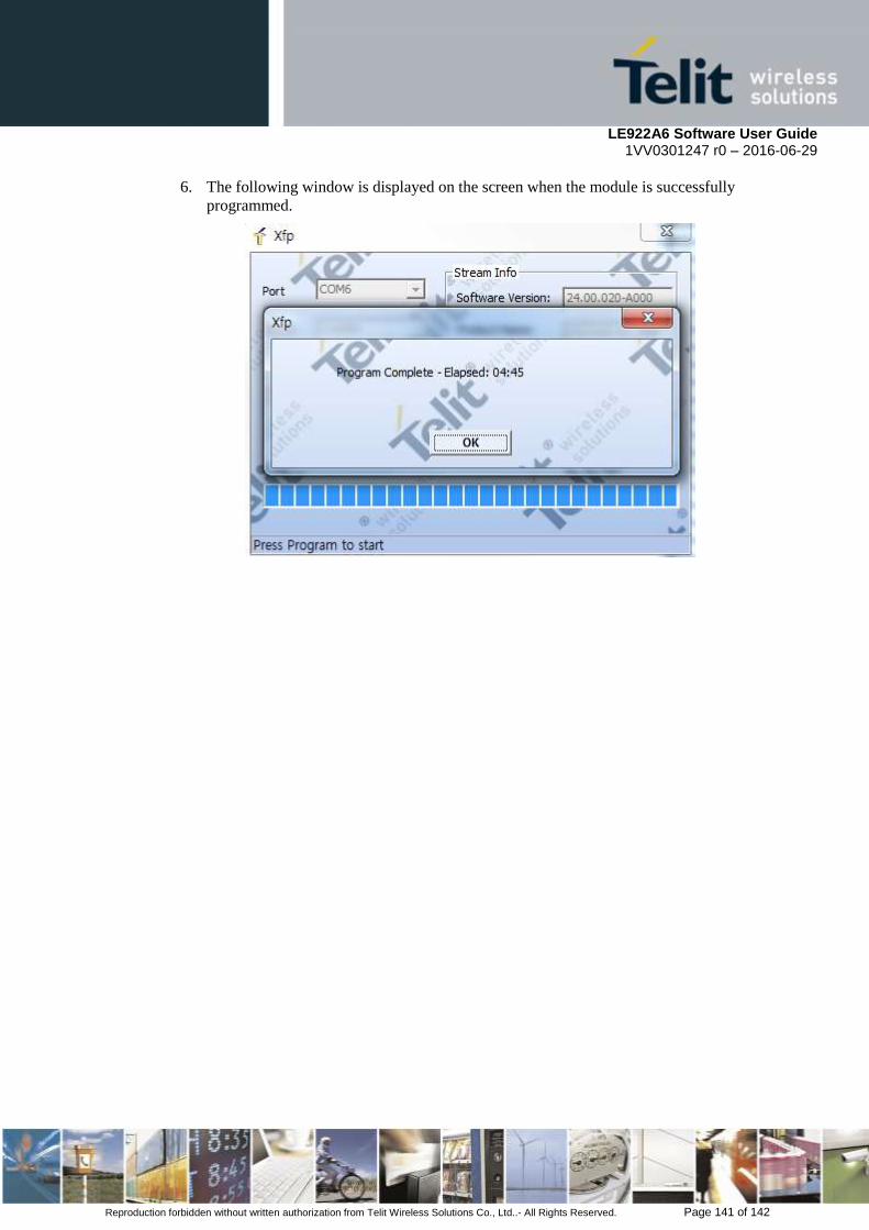
LE922A6 Software User Guide 1VV0301247 r0 – 2016-06-29
Reproduction forbidden without written authorization from Telit Wireless Solutions Co., Ltd..- All Rights Reserved. Page 141 of 142
6. The following window is displayed on the screen when the module is successfully
programmed.

LE922A6 Software User Guide 1VV0301247 r0 – 2016-06-29
Reproduction forbidden without written authorization from Telit Wireless Solutions Co., Ltd..- All Rights Reserved. Page 142 of 142
8. Document History
Revision Date Changes
0 2016-06-29 Initial version