swarm behaviour for path planning - freie universität · swarm behaviour for path planning ... is...
TRANSCRIPT

Masterarbeit
Swarm Behaviour for Path Planning(Schwarmverhalten bei der Fahrplanung)
Freie Universität Berlin
Institut für Informatik
Arbeitsgruppe Intelligente Systeme undRobotik
Studiengang Master Informatik
Vor- und Zuname: Simon Sebastian RotterMatrikelnummer: 4639055ausgegeben am: 12. Mai 2014abgegeben am: 12. November 2014Erstprüfer: Prof. Dr. Raúl RojasBetreuer: Fritz Ulbrich

Simon S. Rotter
Danksagung
Mein besonderer Dank gilt Herrn Prof. Dr. Raúl Rojas der das Projekt AutoNOMOS ander Freien Universität Berlin begründete und durch den diese Arbeit möglich wurde. Seinezahlreichen Hinweise und Einschätzungen, die aus fachlichen, ideenreichen, als auch kritischenDiskussionen über das Thema der Arbeit hervor gingen, trugen entscheidend zum vorliegendenErgebnis bei. Ich möchte mich besonders für seine Unterstützung bedanken.
Weiter möchte ich mich bei Fritz Ulbrich bedanken, der die Betreuung der vorliegenden Master-arbeit an der Freien Universität Berlin übernahm. Seine zahlreichen Hinweise und Einschätzun-gen, sein Expertenwissen zu verschiedensten Themen der Informatik und sein umfassendes Wis-sen über das Projekt mit seinen Implementierungen, trugen entscheidend zum vorliegendenErgebnis bei. Ich möchte mich besonders für seine fachkundige Unterstützung und Führungbedanken.
Auch möchte ich mich bei Dr. Daniel Göhring bedanken. Seine Hinweise, sein Wissen überdas Projekt, insbesondere die Hardware des Testträgers und die Diskussionen waren an vielenStellen hilfreich.
Dank geht auch an Tinosch Ganjineh für seine Mitentwicklung der Hard- und Software Test-plattform MadeInGermany. Weiter war die Zusammenarbeit mit den vielen Mitgliedern desTeams der AG Intelligente Systeme und Robotik am Institut für Informatik der Freien Univer-sität Berlin sehr bereichernd. Zahlreiche fachliche Diskussionen - u.a. in den Montangsmeetings- verhalfen zu Einblicken in die bisherige Implementierung des Projekts und zum Verständnisbisheriger Ansätze. Ideen wurden immer kritisch hinterfragt, was ebenfalls sehr gewinnbringendwar. Weiter möchte ich mich für den Zugang zu dem bereits vorhandenen Wissen des Projek-tes - welches über viele Jahre und durch viele Beitragende entstand - bedanken, was mir einenguten Einstieg in die Thematik meiner Arbeit ermöglichte, als auch eine Anknüpfung an Imple-mentierungen ermöglichte. Weiter möchte ich allen danken, die mich während der Anfertigungmeiner Arbeit unterstützten.
Meinen Eltern möchte ich hier auch besonders für die entgegengebrachte Unterstützung in vielerHinsicht während des gesamten Studiums und gerade in den letzten Monaten danken, womitmir sehr viel ermöglicht wurde.
Simon Sebastian RotterBerlin, Nov 2014
i
Simon S. Rotter
Acknowledgment
My special thanks go to Prof. Dr. Raúl Rojas for initiating the AutoNOMOS Project at theFreie Universität Berlin. He made this work possible. His advice and his numerous hints andevaluations were evolving from professional, imaginative and critical discussions about this the-sis. This essentially contributed to the outcome of this work. I hereby especially want to thankhim for his support.
Further I particularly want to thank Fritz Ulbrich for his great supervision. His numeroushints, evaluations, his expertise about different topics of different fields of computer science andespecially his comprehensive knowledge about the project and its implementations were con-tributing to the result of this work. I especially want to thank him for his competent supportand guidance.
I want to thank Dr. Daniel Göhring for his hints and sharing his knowledge about the project,in particular the hardware of the test carrier. The discussions were helpful at different places tounderstand the overall context of the project.
I want to thank Tinosch Ganjineh for his contribution in developing the hard and softwaretest platform MadeInGermany. Further the cooperation with the many members of the team ofthe AG Intelligente Systeme und Robotik at the Institut für Informatik of the Freie UniversitätBerlin was very rewarding. Numerous competent and technical discussions - for example theweekly sessions so called "Montagsmeetings" - were helping to get insights into current imple-mentations of the project and to understand current approaches. Ideas were always questionedin a critical way, which was very rewarding. Further I want to thank for getting access to theexisting broad knowledge of the project. It has been evolved through many contributors overmany years. This was very helpful to find a good entrance to the theme of my work in thesurroundings of the existing project. This was helpful for a connection of new implementations.Further thanks go to all people how supported me in any way during my thesis.
Many thanks go to my parents for their support in many respects. Especially during my studiesand the during last months.
Simon Sebastian RotterBerlin, Nov 2014
ii

Simon S. Rotter
Abstract
Swarms are a known and studied phenomenon in biology. In different scientific fields transferringof the swarm ideas is done to solve specific problems. In computer science swarm approaches areapplied from computer graphics till mobile robotics. The main contribution of this master thesisis to transfer swarm behaviour to the autonomous car context of the AutoNOMOS Project ofthe Freie Universität Berlin - A Swarm Behaviour for Path Planning. Therefore a processingpipeline is developed, which generates a driving plan for the autonomous car from swarm baseddata. A detailed description of the different processing steps is given. The steps include thetopics: 1) Swarm member selection, 2) velocity matching, 3) swarm member trajectory basedpath planning, 4) abstracting data from swarm member trajectories to generate clustered data,5) cluster based path planning, and 6) plan smoothing with linear regression. Furthermore thedeveloped approach is evaluated and experimental results in simulation and live tests on theautonomous car MadeInGermany are provided.
iii

Contents
1 Introduction 11.1 Motivation . . . . . . . . . . . . . . . . . . . . . . . . . . . . . . . . . . . . . . . 1
1.1.1 Limitations of Map Based Path Planning . . . . . . . . . . . . . . . . . . 11.1.2 Swarm Based Improvements . . . . . . . . . . . . . . . . . . . . . . . . . . 2
1.2 Requirements . . . . . . . . . . . . . . . . . . . . . . . . . . . . . . . . . . . . . . 41.3 Contribution . . . . . . . . . . . . . . . . . . . . . . . . . . . . . . . . . . . . . . 4
1.3.1 Application of Swarm Based Approaches in the AutoNOMOS Car . . . . 41.3.2 Testing Under Controlled Conditions . . . . . . . . . . . . . . . . . . . . . 5
2 AutoNOMOS Projekt 72.1 The AutoNOMOS Project . . . . . . . . . . . . . . . . . . . . . . . . . . . . . . . 7
2.1.1 History, Current State and Achievements . . . . . . . . . . . . . . . . . . 72.1.2 The AutoNOMOS Car . . . . . . . . . . . . . . . . . . . . . . . . . . . . . 7
2.2 Framework . . . . . . . . . . . . . . . . . . . . . . . . . . . . . . . . . . . . . . . 102.2.1 Software/System Architecture . . . . . . . . . . . . . . . . . . . . . . . . . 102.2.2 Orocos . . . . . . . . . . . . . . . . . . . . . . . . . . . . . . . . . . . . . . 112.2.3 Visualisation . . . . . . . . . . . . . . . . . . . . . . . . . . . . . . . . . . 122.2.4 Environment and Further Tools . . . . . . . . . . . . . . . . . . . . . . . . 12
3 Related Work 133.1 Swarm in Biology . . . . . . . . . . . . . . . . . . . . . . . . . . . . . . . . . . . . 133.2 Basic Swarm Approaches in Different Fields of Computer Science . . . . . . . . . 15
3.2.1 General Application of Swarm Based Ideas . . . . . . . . . . . . . . . . . 153.2.2 Application in Computer Graphics . . . . . . . . . . . . . . . . . . . . . . 15
3.3 Current Swarm Approaches in Mobile Robotics . . . . . . . . . . . . . . . . . . . 15
4 Implementation of Swarm Based Approaches for Path Planning 174.1 Basic Idea of a Swarm Behaviour Module in the AutoNOMOS Project . . . . . . 174.2 General Processing Pipeline . . . . . . . . . . . . . . . . . . . . . . . . . . . . . . 194.3 Components of the Processing Pipeline . . . . . . . . . . . . . . . . . . . . . . . . 21
4.3.1 Object Detection and Selection of Swarm Members . . . . . . . . . . . . . 214.3.2 Velocity Matching . . . . . . . . . . . . . . . . . . . . . . . . . . . . . . . 234.3.3 Swarm Member Trajectory Processing . . . . . . . . . . . . . . . . . . . . 264.3.4 Trajectory Based Path Planning . . . . . . . . . . . . . . . . . . . . . . . 284.3.5 Clustering of Swarm Member Trajectories . . . . . . . . . . . . . . . . . . 354.3.6 Building a Local Map From Clustered Swarm Member Trajectories . . . . 404.3.7 Cluster Based Path Planning . . . . . . . . . . . . . . . . . . . . . . . . . 414.3.8 Smoothing the Swarm Plan Data . . . . . . . . . . . . . . . . . . . . . . . 444.3.9 Interface to the Controller Module . . . . . . . . . . . . . . . . . . . . . . 45
5 Evaluation - Experiments and Tests 475.1 Test Cases . . . . . . . . . . . . . . . . . . . . . . . . . . . . . . . . . . . . . . . . 475.2 Evaluation of Different Heuristics in the Simulator . . . . . . . . . . . . . . . . . 475.3 Evaluation of the Clustering of Swarm Member Trajectories . . . . . . . . . . . . 52
iv

Simon S. Rotter Contents
5.4 Live Experiments with the Test Carrier . . . . . . . . . . . . . . . . . . . . . . . 55
6 Conclusion and Future Work 576.1 Conclusion . . . . . . . . . . . . . . . . . . . . . . . . . . . . . . . . . . . . . . . 576.2 Future Work and Outlook . . . . . . . . . . . . . . . . . . . . . . . . . . . . . . . 59
6.2.1 Advanced Velocity Matching . . . . . . . . . . . . . . . . . . . . . . . . . 596.2.2 Improved Static Obstacle Avoidance . . . . . . . . . . . . . . . . . . . . . 596.2.3 Improved Dynamic Obstacle Avoidance . . . . . . . . . . . . . . . . . . . 606.2.4 Building Advanced Maps . . . . . . . . . . . . . . . . . . . . . . . . . . . 606.2.5 Propagating Swarm Based Data . . . . . . . . . . . . . . . . . . . . . . . 606.2.6 Intention Recognition with Swarm Based Data . . . . . . . . . . . . . . . 616.2.7 Advanced Heuristics . . . . . . . . . . . . . . . . . . . . . . . . . . . . . . 61
v

List of Figures
1.1 Ego car, and swarm members with their trajectories . . . . . . . . . . . . . . . . 4
2.1 Autonomous test carrier - MadeInGermany (MIG) . . . . . . . . . . . . . . . . . 82.2 Basic hardware and sensor ranges of the test carrier . . . . . . . . . . . . . . . . 92.3 Autonomous car - iMiEV . . . . . . . . . . . . . . . . . . . . . . . . . . . . . . . 102.4 Overfiew of the general software architecture (taken from [Wan12, p. 64] ) . . . . 11
3.1 Different kinds of swarms in nature . . . . . . . . . . . . . . . . . . . . . . . . . . 13
4.1 Trajectories of swarm members . . . . . . . . . . . . . . . . . . . . . . . . . . . . 184.2 Schematic processing pipeline . . . . . . . . . . . . . . . . . . . . . . . . . . . . . 194.3 General architecture for swarm behaviour related tasks and interfaces . . . . . . 204.4 Processing pipeline of the swarm member classification process . . . . . . . . . . 214.5 Swarm members with their trajectories . . . . . . . . . . . . . . . . . . . . . . . 224.6 Velocity matching scenario . . . . . . . . . . . . . . . . . . . . . . . . . . . . . . . 244.7 Pipeline for extracting, managing and refinement of trajectories of swarm members 264.8 Visualization of obstacles, swarm members and trajectories . . . . . . . . . . . . 274.9 Pipeline for building a plan from trajectory data of swarm members . . . . . . . 284.10 Selection of trajectories by concerning reachability . . . . . . . . . . . . . . . . . 294.11 Definition of a "Safety Zone" . . . . . . . . . . . . . . . . . . . . . . . . . . . . . . 314.12 Selecting trajectories by investigation of one "Safety Zone" . . . . . . . . . . . . . 314.13 Selecting trajectories by using prioritized "Safety Zone"s . . . . . . . . . . . . . . 324.14 Plan generation based on trajectories of swarm members . . . . . . . . . . . . . . 344.15 Schematic idea of the clustering process . . . . . . . . . . . . . . . . . . . . . . . 364.16 Pipeline of the clustering process . . . . . . . . . . . . . . . . . . . . . . . . . . . 394.17 Cluster generation for a roundabout . . . . . . . . . . . . . . . . . . . . . . . . . 404.18 Connected Clusters . . . . . . . . . . . . . . . . . . . . . . . . . . . . . . . . . . . 424.19 "Cluster" generation with swarm based data from a roundabout . . . . . . . . . . 434.20 Smoothed swarm based plan, based on swarming data . . . . . . . . . . . . . . . 444.21 Pipeline for building a plan and handing it over to the vehicle controller . . . . . 46
5.1 Evaluation in roundabout scenario . . . . . . . . . . . . . . . . . . . . . . . . . . 485.2 Evaluation of the Clustering Process . . . . . . . . . . . . . . . . . . . . . . . . . 535.3 Evaluation of the Clustering Process - with method from [GLJ10] . . . . . . . . . 545.4 Approximating the course of the road with different methods . . . . . . . . . . . 545.5 Testarea - Tempelhofer Feld in Berlin - area, obstacles and test carrier . . . . . . 55
vi
List of Tables
1.1 Requirements . . . . . . . . . . . . . . . . . . . . . . . . . . . . . . . . . . . . . . 5
5.1 Evaluation of the "Angle Based Trajectory Selection" heuristic . . . . . . . . . . . 495.2 Evaluation of the "Trajectory Selection by Safety Zone Below the Ego Vehicle"
heuristic . . . . . . . . . . . . . . . . . . . . . . . . . . . . . . . . . . . . . . . . . 495.3 Evaluation of the "Trajectory Selection by Three Safety Zones in the Ego Vehicle
Area" heuristic . . . . . . . . . . . . . . . . . . . . . . . . . . . . . . . . . . . . . 505.4 Evaluation of the "Closest Cluster - Longest Successor" heuristic . . . . . . . . . 505.5 Evaluation of the "Closest Cluster - Most Confident Successor" heuristic . . . . . 515.6 Evaluation of the "Closest Cluster - Minimal Direction Change Successor" heuristic 515.7 Comparision of the different heuristics . . . . . . . . . . . . . . . . . . . . . . . . 52
vii

1 Introduction
1.1 Motivation1.1.1 Limitations of Map Based Path PlanningIn general, a driving car is connected with the task to know where the car can drive and howfast it can drive. Consequently one of the main problems in autonomous driving is how to find adriving plan, on which the car is able to go. A driving plan (short called plan) in this context isa planned intended future trajectory (driving path) for the car. It consists of way points in theenvironment and a speed which is given to the car controller. The car controller is responsiblefor reaching this way points with an appropriate speed. This speed must be smaller than orequal to the allowed speed. Further this speed must be below or equal the maximum speed thecar hardware can cope with. Especially in unfamiliar, dynamic and unpredictable situations thisis challenging. Different problems occur in this context:
• Is a street available where the car can drive?
• Where is this street?
• In which direction can the car go? In scenarios with different lanes, there are existingsituations with different directions at different times during a day.
• What is the current state of the traffic?
• How fast is the car able to drive?
• Are there lanes which are more preferable than others? This has to be considered fromcertain point of views: e.g. how likely is it to stay on a lane or alternatively, are often lanechanges probable? Which is the fastest lane? Which is the safest lane?
• and so on.
Current solutions are based on given maps, which are predefined. Information is pre knownabout the environment (traffic lights, number of lanes on the street, speed limits ...) and storedin these maps. The autonomous car is using this information to calculate an intended own tra-jectory at the middle of a lane. See for a current state and implementations in the AutoNOMOSProject [Wan12].
A driving plan is generated, based on this predefined information from maps, by the softwareof the autonomous car. Therefore information from sensors like GPS (Global Positioning Sys-tem), odometer or IMU (Inertial Measurement Unit) are taken into account. Thus the currentposition of the car is determined. Further the autonomous car refines points from the plan (e.g.GPS points) which it wants to reach. Velocities at this points are also given from the maps.A car controller controls the actuators of the car in a way, that the wanted aims are reached.Reactive interaction takes part during execution in the case of obstacles which may occur onthe plan and in the case that collisions could happen. This is called reactive break. For fur-ther details about the controller architecture of the AutoNOMOS Project and the usage of a
1

Simon S. Rotter Chapter 1. Introduction
controller in an autonomous car and further related ideas see [Göh12], [GWSG11] and [Wan12].See further explanations around the autonomous car in the descriptions of Chapter 2.
With this current state situations can be handled which are very static. A lot of data has tobe known exactly before execution. The GPS points of the streets are needed - a map. Anddata about the velocities at that points must be pre known - stored in that map. Reactively,obstacles are taken into account by the controller of the autonomous car. But what happens inthe case of changes and highly reactive changes in which not enough pre known data is availableabout the infrastructure? Examples for such cases are:
• Roads are connected with changes, in general: So roads can be changed or can disappearover the time. This will lead to problems in the case of autonomous driving, if the "old"known map is not up to date. Or in other words - maps have to be hold in a very currentstate.
• Highly reactive changes can happen on the streets: Accidents, changing weather conditionsand so on. This changes may happen so fast, that they cannot be inserted in a map: E.g.a new lane course after such a change: Accidents, dirty roads, snow covered roads, damageon the road surface, and so forth. In such a case the pre known lane data is suddenlyoutdated.
• No GPS data or other global propagated positioning data is available: For example intunnels. And further no Car2X communication data is available - for example becauseof obsolete technology in other cars or different communication standards between thecommunicating units. Further no lane data is present for example because of a newunknown area or outdated maps.
• Traffic situations like in roundabout traffics, where cars are taking lanes which are dif-ferent from the marked lanes. Or in general, if no lane markings are available. But carswith human drivers are orientating themselves on each other to pass through the trafficsituations. This may happen in very chaotic traffic conditions. No pre known data aboutthe "actual used" lanes is available in this situations.
In these cases a solution is preferable which copes with such situations or at least make im-provements, if it is used in addition to the solutions of the current state. So if one of theabove described conditions is present, such a solutions helps the autonomous car to continueautonomous driving. A way is findable to manage the current situation. This is object of thisthesis. To find a solution for exactly this problem.
1.1.2 Swarm Based ImprovementsAbove described problem situations mostly involve other traffic. Other cars are on the streets.Other traffic participants are still driving and are able to perceive the current traffic environ-ment (streets, lanes, ...) and the changes of the environment (construction works, snow coveredlanes, ...). The single entities of the traffic take such information into account. This definestheir own driving habit. Thus participating traffic is a valuable source for exactly the kind ofinformation, which cannot be pre known for the autonomous car through maps. So throughperceiving the habits of other traffic participants, help is given for the autonomous car to act ina way that the above described problems are solvable. For example a situation in which vehiclesare driving through a roundabout. Following vehicles will orientate itself towards the leadingvehicles. Thus driving lanes are defined by the traffic itself. This may be different from the lanemarkings. Even if no lane markings are available, "driving lanes" are defined by the traffic. If
2

Simon S. Rotter Chapter 1. Introduction
the autonomous car follows that traffic members and takes their driving habit into account todefine the own driving plan, no map data is needed to pass through the roundabout.
In this context, an important fact is, that at the moment most traffic participants are hu-mans. These participants are able to react to changes in an intuitive way. Embedded into thisenvironment it is perfect for an autonomous car to orient itself towards this traffic participantswhich are having more foresight. But this approach is not only restricted to the use case ofhuman traffic participants. Even in an environment with only autonomous vehicles, all trafficparticipants in front of the autonomous car can perceive another part of the environment orhave more vision. This is a positive effect if that information is used by the ego vehicle in anintelligent enough way. So even in the case of not human drivers an orientation towards othervehicles respectively an taking into account of the habits of the other traffic participants and aselection of them can lead to a gain.
So in that context cars in front of other cars give exactly three very essential information:
• Possible way points: If a car was driving through a certain point in the environment a fewseconds before (and given that there where no abnormal happenings like accidents afterit). Then at this point the own autonomous car can drive, too. Assumed it can reach it.
• Connection of possible way points: If a perceived car was reaching different way pointsover some time, then this is an indicator for a possible way between that way points.
• Speed: If a car is driving at a certain point with a certain speed, then it is highly probable,that the autonomous car can go through this point with the same velocity (or less if thehardware is not allowing it), because they are driving there with no problem.
• (Direction: included in above points because speed can be seen as a vector with directionand connections between points include that information)
In all points a temporal connection has to be given, which is small enough. Means that allsituations underlie the time component. If too much time is elapsing between an observation,an usage is more likely to be impossible because the situation is changing over the time.
So an orientation of the autonomous car towards other traffic participants is usable to getinformation and later solutions for coping with the current traffic situation. That informationcombined and adjusted to the needs of the current situation of the autonomous car leads to animprovement of the current state. All of the descriptions in this subsection leads to the need forresorting to current knowledge in the swarm area.
As described before, situation specific information about the environment can be obtainedfrom perceiving the surrounding of the agent. If the agent is orientating itself towards otheragents, this can be compared with a swarm (see Figure 1.1). Swarms were described in biologyand are used in different scientific fields. There have been made different approaches to describeor use the currently known insights into swarms. Facts about the current state of the swarmtopic can be read in more detail in Chapter 3. If basic concepts are understood and transferredto the area of autonomous driving cars, there will be a strong and powerful tool to handlethe described situations. An application of the swarm ideas is described in Section 4 and anevaluation is provided - Section 5.
3

Simon S. Rotter Chapter 1. Introduction
Figure 1.1: Ego car, and swarm members with their trajectories
1.2 RequirementsTo reach this aim different requirements are defined. To transfer the swarm based idea intothe autonomous car context of this project different points have to be reached. In Table 1.1basic points are summarized. The AutoNOMOS Project of the Freie Univesität Berlin has anexperimental vehicle which is able to drive autonomously (described in more detail in Chapter2). Object of this work is it to contribute a component to the software which extends the currentsolution through swarm based approaches (REQ01). In this context it is important to transferthe ideas of swarms into the context of autonomous cars in (daily) traffic (REQ02). These ideashave to be implemented in software - so algorithms are needed to realize this (REQ03). Furtherappropriate data structures are required to get to that aim (REQ04). One important task is toembed this piece of software into the current software/hardware architecture. So interfaces areneeded (REQ05). And further an appropriate way has to be found to integrate the currentlyavailable data which is already achievable through the current implementations (REQ06). Inaddition tests have to be made. On the one hand side simulations have to be done to test firstimplementations (REQ07). For the simulations, there will be need for a way to visualize theprocessing (REQ08). And on the other hand side real tests with the test carrier have to bedone to validate if it is working under real conditions (REQ09).
1.3 Contribution1.3.1 Application of Swarm Based Approaches in the AutoNOMOS CarMain part of this thesis is to implement a module with algorithms and heuristics. This mod-ule is called "Swarm Behaviour Module" and applies swarming approaches. The output of themodule is used to realize a swarm based path planning. Thus a swarm based behaviour isadded to the project. There is currently existing a non swarm based behaviour. This behaviourworks with pre given maps and reacts on dynamic obstacle changes. The "Swarm Behaviour" ofthe present work should be seen as a complement to that existing and established behaviour. Itcan be further seen as an extension for specialized circumstances as for the cases described above.
Further through the contribution of this work a "sub framework" emerged for the swarm be-haviour. This can be used in the AutoNOMOS Project and it can be further developed andadopted to new requirements concerning swarm ideas. In general, the implemented ideas canbe divided into two subcategories: Once a swarm member trajectory based path planning. And
4

Simon S. Rotter Chapter 1. Introduction
REQ01 Swarm based extension of the current software solution for the autonomoustest carrier
REQ02 Using swarm based ideas for the context of autonomous cars in traffic
REQ03 Implementation of algorithms to realize swarm based ideas for autonomousdriving
REQ04 Implementation of data structures to realize swarm based ideas forautonomous driving
REQ05 Embed implemented software into the current AutoNOMOS Project architectureand define interfaces to existing modules
REQ06 Integrate data of current project modules
REQ07 Test implementations through simulation
REQ08 Visualize the swarm based data
REQ09 Real live tests with a test carrier of the AutoNOMOS Project
Table 1.1: Requirements
further a path planning based on abstracted trajectory data. In the last case, redundant datais used in a merging process to obtain more robust swarm based data.
While the swarm behaviour part is qualified for active interaction of the car, there is anothergain for the project based on the swarm approach. Maps of current accessible traffic lanes onstreets can be obtained. This is also usable for swarm based path planning. Further it is a pos-sibility to gather information about the environment for further usage like exchange of currenttraffic data and build up of general driving maps in new locations. For this application a basicframework is provided, which can be used for applications in future work connected with swarmbased path planning.
1.3.2 Testing Under Controlled ConditionsFurther extensive testing is part of this work. As autonomous driving is connected with highsafety risks for traffic participants if the software is not working properly. It it is important totest new software modules extensively. In that way not foreseen reactions of the software canbe observed. So the software can be adapted and improved, based on that insights. Thereforea process with more steps during different phases was used to cover good testing:
Implementation
First the basic ideas were implemented. Swarm approaches were adopted to the autonomouscar context and algorithms for heuristics derived. They were basically tested so that the soft-ware was running. Further data exchange of modules was tested. Important was to test theexecutability in connection with the existing modules of the project to exchange data.
5
Simon S. Rotter Chapter 1. Introduction
Testing With Logged Data
Further logged data from past autonomous test drives were used. For that test drives a testcarrier was used which is able to log different sensor and actuator data of the car. For furtherdescriptions see Chapter 2. This was useful for the testing of the swarm behaviour implementa-tions of this work. Specialized sensor data in special situations is used as input for the swarmbehaviour implementation. So reactions of the swarm behaviour module in exactly that situ-ations could be analysed. Special test situations in traffic could be classified into different usecases:
• Straight Stretches: One ore more lanes are going straight.
• Curves: Curved course of the roads.
• Roundabouts: Most demanding tests which includes above cases.
If considered roundabouts in combination with its entry and exit it contains the other cases.This case was consequently taken as a reference for most tests. The logged data of a real testcarrier drive were used. The temporary reactions of the swarm behaviour module were analysedat certain points in the logged data. This allowed a fine tuning of the module.
Testing in a Simulator
As soon as the tests with the logged data caused a satisfying result tests with a simulator wereperformed. Here the habits of a "virtual" autonomous car can be executed and observed. Thetest is based on some logged data like in the phase before. In difference the simulator testallows to carry out longer and more complete tests. Further the logged data is used as inputand is timely connected as in real life. Processing of the swarm data takes place. The outputis given to the simulated hardware. A model car is carrying out the commands time related tothe current logged situations. In that way a pre observation of the swarm behaviour module inreal situations in connection with the autonomous car were checked.
Testing with an Autonomous Test Carrier
When the tests with the simulator were completed and reached a satisfying result, live tests withan autonomous test carrier (see Chapter 2) could be carried out. This is a similar interaction ofthe modules as in the test before but with a real car and real traffic environmental conditions.The car gets the control commands of the data processing modules and carries them out. Asafety driver observes the habits of the car and intervenes if necessary. Therefore the specialtest area Tempelhofer Feld in Berlin was used. So that normal traffic and humans cannot beendangered.
6

2 AutoNOMOS Projekt
2.1 The AutoNOMOS ProjectThis work was developed under the AutoNOMOS Project of the Artificial Intelligence Groupof the Freie Universität Berlin (see [Laba]). The project has its roots in 2006 and gainedexperience with different research topics around autonomous driving over the years till today.A more detailed description of the project and the test carrier follows.
2.1.1 History, Current State and AchievementsThe project has different test carrier vehicles which are able to drive autonomously. Firstapproaches were made with the car “Spirit of Berlin” in 2007 (see [Labc]). Later the car“MadeInGermany” were added (see [Labb]) and is applied nowadays together with an elec-tric car called “iMiEV”. These cars are used for testing new research topics and approacheslike in this work. The experimental vehicle used for testing the implementation of the swarmapproaches is “MadeInGermany” and is introduced below.
In 2007 the project was taking part in the DARPA Urban Challenge - where autonomous carsof different teams were participating [RRG+07, p. 2f.]. In that challenge real traffic scenarioshad to be managed by the autonomous car. Further one of the main tasks was to develop theautonomous car so that it is able to coexist in the daily traffic of a crowded city. This wasachieved in the city Berlin where “MadeInGermany” is able to drive (compare [Wan12, p. 49]).Over the years the basics of the project have been built out. New projects were evolving likethe “Intelligent Wheelchair”, “Pick me up!”, “iDriver” or “BrainDriver” (see [Laba]). Currentprojects are focussing on new research topics and improvements of existing approaches.
Nowadays the AutoNOMOS Project provides a framework for new sub projects and ideas.With its test carriers a hardware architecture is available. Further there was evolved a softwarearchitecture with different working modules on different abstraction layers. So new ideas can beintegrated and set up on the current foundation. Below a description follows, how the currenthardware and software architecture is used to reach the aim of this work.
2.1.2 The AutoNOMOS CarDifferent test carriers have existed in the AutoNOMOS Project. For the integration of theswarm behaviour approach into the project the autonomous car “MadeInGermany” has beenused. A picture of the test carrier can be seen in Figure 2.1. It is based on the VolkswagenPassat Variant 3c which is used as the basic driving platform (see [Labb]). It has an automaticgearbox and is extended with further hardware. Via the CAN-Bus (Controller Area NetworkBus used in vehicles to communicate data between sensors and actuators) data can be receivedfrom and given to the platform of the Passat. So an extension of the platform with furtherhardware is possible and a communication to the platform is achieved. For different built insensors see Figure 2.2a from [Labb]. The sensors can be classified into groups. So a GPS (GlobalPositioning System) module, an IMU (Inertial Measurement Unit) module and an Odometer isused for the tasks connected with the localization of the car. Vision systems, Laser scanners and
7

Simon S. Rotter Chapter 2. AutoNOMOS Projekt
Figure 2.1: Autonomous test carrier - MadeInGermany (MIG)
radar modules are used to perceive the environment of the car to enable further tasks connectedwith environmental observation. For a more detailed description of these hardware modules seebelow. For testing the swarming ideas at least one other car is needed in the test scenarios. Forthat reason the second test carrier iMiEV (see Figure 2.3) was applied.
Sensors for Self Navigation
Different sensors for self navigation are integrated. In the context of robots - especially au-tonomous cars - it is important to know the own position and further information like the ownvelocity. Such values of the own car are called "ego" data in the following. Ego data is neededfor swarm based applications because the own data (especially position and speed) is needed.This data is further essential in relation to the data of swarm members. An Odometer is usedto get data about the position and alignment of the car. Rotations of the wheels are counted.A covered distance can be calculated with that data. A GPS (Global Positioning System)antenna is integrated to additionally get position and alignment data of the car. Further thevelocity of the car is obtainable. An IMU (Inertial Measurement Unit) is built inside thecar. It is used to get more appropriate data about the position and speed of the car via mea-surement of inertia. This is required because in standard traffic contains areas where the GPSis not available e.g. in tunnels or if there is longer no GPS covering in some area.
Sensors for Environment Perception
If the own data about the car through the above described sensors is known, it is furtherimportant to percept the environment. In the swarm context it is necessary to get data aboutobstacles in the surroundings of the ego car. This information about obstacles is used to findmoving objects which can be used as swarm members. The integrated Velodyne Lidar (lightdetection and sending) unit is of type "HDL-64E LiDAR". It sends out laser beams to measurethe distance to objects in the environment. It is using a concept of a rotation of 64 laser beamsto get a relatively detailed point cloud of the environment of the car. Through rotation a 360degree view is possible. One TRW radar with a field of view of 12 degree and distance rangeof 200 meters - see [GWSG11] is further integrated. The radar is used to get object information.Further a SMS radar is used. Six ibeo Lux laser scanners are used for object information.They have a relatively wide field of view of 110 degree (horizontal) and a distance range of 200meters - see [GWSG11]. Different types of cameras are used for Vision. They are applied for
8

Simon S. Rotter Chapter 2. AutoNOMOS Projekt
(a) Autonomous car - Sensors ofMadeInGermany (from [Labb])
(b) Autonomous car - Sensorrange of Lux Laser Scannerand TRW Radar (from [GWSG11])
Figure 2.2: Basic hardware and sensor ranges of the test carrier
different advanced projects. E.g. special Object detection like traffic lights.
Sensor Data Fusion
Different sensors are used to additionally get a (nearly) 360 degree sight around the car - seeexemplary Figure 2.2b from [GWSG11]. This is important in the swarming context to perceptthe environment for possible objects usable as swarm members. For sensor data fusion used inthe project see [GWSG11]. The basic idea is to take the advantages of the different sensors andcombine them to overcome the special weaknesses of the single sensor types. Equally the coverrange of a single sensor is fixed. So combining data of more single sensors of the same type indifferent direction leads to a wider view. In that way a 360 degree panorama view (at a certaindistance to the car) can be reached. Further the distance range of sensors reaches up to 200meters. So a relatively huge area around the car can be observed. For this purpose see Figure2.2b were by way of example the combination of different Lux sensors together with the TRWradar is shown. A detailed description of the concept of the sensor fusion in the project can befound in [GWSG11]. Combining the data of the different sensor sources leads to the ability todetect obstacles and their characteristics. Examples are:
• size of obstacle
• speed
• direction
This data is fundamental for the swarm behaviour concepts. So the information gained by thesensor data fusion is basic for this work. The sensor based information is treated as abstractedfrom the sensors throughout the work.
Safety
A special safety concept is used in the project. In detail it is described in [GWSG11] and in[Wan12] (especially see Chapter 3.4 about the Software System Architecture and Chapter 7about the low level controller). A generated plan with positions and velocities is handed overto a low level controller of the autonomous car. At that level safety checks are accomplished.Positions and velocities of obstacles are used to calculate a safe own velocity and distance. Ifdistance and velocity to obstacles are not appropriate a break is performed.
9

Simon S. Rotter Chapter 2. AutoNOMOS Projekt
Figure 2.3: Autonomous car - iMiEV
2.2 Framework2.2.1 Software/System ArchitectureThe autonomous car can be seen as a robot agent. It has sensors to perceive the environment.Furthermore it has actuators to change the state of the environment - or better in this contextto navigate through the environment. Between perception and actuation there is need of someprocessing. Therefore different modules are used which are responsible for solving differenttasks. For this work a module for doing the processing for the swarm behaviour was created. Itwas integrated into the existing software architecture. Modules can be classified into differentareas connected to localization, perception and computer vision, navigation and further moduleswhich are managing the data flow to the hardware of the car. The general idea of the softwarearchitecture with data flows can be seen in Figure 2.4 from [Wan12, p. 64]. According to thework of Miao Wang [Wan12] the module categories have the following tasks:
• Vehicle Data and Localization Modules: responsible for providing data from the vehicleand data about the position - interface to the hardware of the car.
• CV (Computer Vision) Environmental Perception Modules: providing data about theenvironment based on cameras.
• 3D Environmental Perception Modules: providing data about the environment based onlaser scanner, radar and ultrasonic hardware.
• CN (Cognitive Navigation) Modules: here the the logical modules are located which areconnecting and processing the data of the different other modules described above.
• Control and Actuator Modules: are the interfaces between the logic and the vehicle. Sothat the vehicle can perform the orders of the logical processing.
The module for swarm behaviour of this work can be integrated into the CN Modules. Itneeds data from the vehicle and localization modules. Further it gets data about objects in theenvironment from the lateral modules. A communication with the hardware takes place via the"Control and Actuator Modules".
10

Simon S. Rotter Chapter 2. AutoNOMOS Projekt
Figure 2.4: Overfiew of the general software architecture (taken from [Wan12, p. 64] )
2.2.2 OrocosAs a basement for the project implementation the “Open Robot Control Software” (OROCOS)is used (see [ra13] and [ra08]). It provides the infrastructure for modules which are able tocommunicate with each other in form of C++ libraries. OROCOS is open source and used innumerous open source projects. To be flexible it has a modular structure, where the interfaceshave to be described well (see [Bru01]).
So called OROCOS-Tasks (TaskContexts) are used to enable a distribution across differentcomputers (compare [RRG+07, p. 6 f.]). These OROCOS-Tasks are code classes, which canprocess code. That tasks have different standard methods which are called at different life-times and which implement different functionalities. One of these methods is called, when theOROCOS-Task is started the first time. Here basic functionalities are implemented to organizeand manage everything so that an OROCOS-Task is able to work in the following phases. Thenthere are methods which can be called periodically or event triggered. Here the general mainfunctionality of a task is implemented. This is the code which mostly is running during themain runtime of the module. Algorithms for the later described "Swarm Behaviour Module" ofthis work are located here. Than there are further methods for functionalities like cleaning upat the end of a lifetime of a module.
An OROCOS-Task can have connections - so called ports. This ports are divided into inputand output ports and are allowing to exchange data. So modular connections between differ-ent kinds of tasks can be established and data objects can be sent between different modules.Therefore functionalities can be distributed in a very modular way which is a big advantage forthis project. For example the logic of the later described "Swarm Behaviour Module" and thevisualisation of the result of the processing can be split. This is especially valuable for testswith the test carrier: visualisation of the current processes/ decisions while execution of theautonomous driving is possible. So interpretation and evaluation of the autonomous behaviourcan take place and is accessible for the safety driver. In the OROCOS context combined withown implementations it is important to think about critical resources and possible deadlocksand use semaphores or mutual exclusions if needed.
11

Simon S. Rotter Chapter 2. AutoNOMOS Projekt
2.2.3 VisualisationFor simulation, test and presentation reasons a kind of visualisation of the implemented ideasis needed. Therefore OpenSceneGraph is used which is “[..] an open source high performance3D graphics toolkit, used by application developers in fields such as visual simulation, games,virtual reality, scientific visualisation and modelling” [Ope12]. It is based on C++ and OpenGL(see OpenGL web page: [Ope14]).
Scene graphs are modeled with the OpenSceneGraph toolkit. So a rendering of all relevantobjects for the swarm behaviour and the car is possible (see simulation pictures throughout thiswork). Connections and data transfers between the logical algorithms of the swarm implemen-tations and the visualisation with OpenSceneGraph is solved by OROCOS tasks and the portconnections (as described above).
Additional visualisation is done directly with OpenGL ([Ope14]). Throughout the work,benefit from the existing project implementations and code examples was possible. In particularthis was helpful in the context of OpenSceneGraph, OpenGL and OROCOS.
2.2.4 Environment and Further ToolsFor integrating modules into the exiting software, XML-files are used. In these files configura-tions parameters are set. Further connections between ports of modules are set. As describedabove, an OROCOS-Task can have different ports. Between ports connections can be estab-lished. Exactly this set up is defined by the XML-files. A tool called "Remotecontrolcentre" isconfigured via this files, too. It is used as a Graphical User Interface (GUI) for simulations andstarting different software modules.
Implementations of a road model are available from the existing project. This was very con-venient for testing the swarm approaches of this work. Because data for a possible visualizationof the "real" roads with its lanes could be used for comparison. Tracked and logged data ismatched onto a map via GPS information for this purpose. With the data of the road modele.g. a comparison of swarm based paths to real world infrastructure can be tested and shown.The used technology for the road model was the Route Network Definition File (RNDF). Forfurther information connected to that topic see [Cze14].
As programming language C++ with related libraries is used. To emphasise is the library"Eigen" - a powerful tool for linear algebra with matrices and vectors (see project page [Eig14]).Linux Ubuntu is the used operating system. Further different tools were used to accomplish theimplementation and the project management. For version managing the tools Git (see [Git])and Mercurial (see [Mer]) were used. Project tools for distributed compiling and simulating wereapplied.
12

3 Related Work
3.1 Swarm in BiologySwarms occur in nature. Different kinds of animals are existing which are known to appearand act in swarms - see for example birds and fishes shown in Figure 3.1. Further examplesfrom biology can be found like bacteria. Consequently swarms can be found in different livingenvironments connected to the elements water, air and land. So nature "built up" the swarmingconcept to cope with different difficulties in these areas as following described. To mentionjust some examples (compare research work dealing with this swarms and related topics e.g.[CRB12], [Rey87], [GGT07], [HW90], [BDT99], [CDF+03], [TZ13]):
• Animals like sheep, cows or horses which are in herds
• Ants (e.g. managing their food provision or building constructions)
• Birds (e.g. flying in groups)
• Fishes (e.g. swimming in schools)
• Bacteria colonies
• Bees (e.g. finding nectar)
Even research around human crowds exists (e.g. see [Cou12] and [TZ13]). A lot of work hasbeen done to try to analyse, to understand and to benefit from that part of the nature. Inthis context the term "swarm intelligence" is mentioned ([GGT07], [CRB12], [BDT99]). Thebasic idea is that many swarm members are acting in a relatively simple way, but the globalbehaviour of the swarm is relatively intelligent and brings gain to the swarm as a whole - see forexample [GGT07] and [CRB12]. An interesting point which came out from the research aboutswarm intelligence is, that individual members of a swarm have only limited knowledge aboutthe global situation (compare [GGT07, p. 5]). So the interaction in the swarm leads to a result
(a) Swarm of birds flying aligned in one direc-tion - from [Tre09]
(b) Swarm of fishes (school) - a directed move-ment can be seen - from [Wan]
Figure 3.1: Different kinds of swarms in nature
13

Simon S. Rotter Chapter 3. Related Work
which can be more than the abilities a single entity can provide. This is exactly what can beused in the autonomous car context - as described later.
Further in literature the word "Stigmergy" is used in the context of social behaviour betweenanimals or agents. It is used to describe how agents are communicating and coordinating them-selves through their actions and the resulting changes in the environment (see e.g. [GGT07,p. 5]). Corne et al. emphasize, that this kind of communication is indirect [CRB12, p. 3 ff.]and compare its fundamental "stigmergy structure" with a notepad which is used by the swarmmembers to leave cues.
Ants navigate with the help of pheromone deposition (which is a kind of stigmergy) to foodsources (see e.g. [GGT07, p. 5] or [CRB12, p. 3]): Ants can set pheromones when a path shouldbe marked. Other ants can follow that trails. In that way paths to food sources can be propa-gated and used amongst the ants. If we see the colony of ants as a swarm, that leads to advantagefor the whole swarm. Food can be transported and consumed by the swarm by using the propa-gated information of single entities. So not all agents have to use their time with searching food.This is one further example, how the "intelligent" behaviour of a swarm can lead to an advantage.
Garnier et al. define four different organising functions between the task of social insects:"Coordination" ("[..] organization in space and time of the tasks required to solve a specificproblem"), "Cooperation" ("[..] individuals achieve together a task that could not be done bya single one"), "Deliberation" ("[..] mechanisms that occur when a colony faces several oppor-tunities") and "Collaboration" ("[..] different activities are performed simultaneously by groupsof specialised individuals") [GGT07, p. 9 ff.]. Keeping that ideas in mind helps to find swarmsolutions for the autonomous car project. Especially the functions "Coordination" and "Coop-eration" were used as a inspiration for the work of this thesis.
As suggested by Garnier et al. knowledge about swarm intelligence can be used for controlalgorithms in artificial agents appearing in groups ("colonies"). So uncertain environments andchanges can be handled (see [GGT07, p. 19]). Current research on understanding "collectivedynamics" is done by P. Romanczuk. In [RSG12] a swarm formation and pattern formation withhelp of "selective attraction and repulsion" is analysed.
As we see there is existing a lot of knowledge from the biology. Research on understandingand transmitting the ideas is done. Compare in this context the descriptions and presentationof the current "research progress of swarm robotics" in [TZ13].
All of this knowledge can be used as an inspiration in the autonomous driving context:
• only locally perceptible environment for the autonomous car (surroundings of about 200meters because of sensor range)
• intended globally good solution (e.g. drive through difficult traffic situations like round-abouts while considering static and dynamic conditions)
• use information perceptible from close by traffic (swarm members)
• no global aware access to the situation
14

Simon S. Rotter Chapter 3. Related Work
3.2 Basic Swarm Approaches in Different Fields of Computer ScienceEven in the area of computer science there has been made efforts to profit from the gain ofswarms. The history of the development of this research area reaches from solving of optimizationproblems to simulations in computer graphics.
3.2.1 General Application of Swarm Based IdeasBonabeau et al. give in [BDT99] a good overview over different applications which have biologicalexamples. Chapter two of [BDT99] gives explanations for "ant-based algorithms or ant colonyoptimization". These algorithms are used for solving optimization problems. Further algorithmsfor data analysis and graph partitioning are introduced by Bonabeau et al. Further examplescan be found in [BDT99]. In this context "the most popular and successful algorithms that areassociated with swarm intelligence" are described in [CRB12] with focus on natural inspiration:"ant colony optimization", "particle swarm optimization" and "foraging algorithms".
3.2.2 Application in Computer GraphicsOne of the fundamental works for the scope of the present thesis is originated in the special fieldof computer graphics. Current works (e.g. [BLLG11]) connected with swarm ideas are usingor discussing Craig W. Reynolds fundamental ideas to describe a swarm in their work. The socalled Reynolds Rules - see [Rey87]. The basic idea was to animate different kinds of swarms likeflocks, herds, schools of animals (in the following the different occurrences are subsumed underthe word swarm) with computers. In his work Reynolds defined three rules which are basic fora swarm model (see [Rey87, p. 4]):
1. Collision Avoidance: avoid collisions with nearby flockmatesshort called separation
2. Velocity Matching: attempt to match velocity with nearby flockmatesshort called alignment
3. Flock Centering: attempt to stay close to nearby flockmatesshort called cohesion
When agents are interacting in a swarm it is important not to collide with other agents.Therefore rule 1 is in the model. Further a swarm has to be kept up. Rule 2 includes thedemand to move and act in a way that the same direction is obtained. To add a rule whichtries to center the swarm rule number 3 is inserted. In combination this rules allows to simulatea swarm and as already mentioned above are basic for current works which are engaged in thetopic swarm and were published after the years of 1987 (see for example [OS06]).
3.3 Current Swarm Approaches in Mobile RoboticsIn the field of mobile robots current approaches have been made to achieve a swarming behaviourof different robots. A. S. Barrera et. al are discussing an approach, based on a method calledParticle Swarm Optimization (PSO), to get a model for swarm behaviour [BLLG11]. Importantfor that method is a given single target, which an agent wants to reach. In their future workthey want to focus on a multi target approach. They see applications in multi-robot systemsand unmanned aerial vehicles (UAV), see [BLLG11, p. 1]. Basics about Particle Swarm Opti-mization can be found in [KE95]. D. H. Kim shows an approach in [Kim10] to obtain a swarmbehaviour in a group of mobile unicycle robots. In his work a modification of the Particle Swarm
15

Simon S. Rotter Chapter 3. Related Work
Optimization technique is shown. He uses an approach were the robots want to reach a certaintarget. See also [KS06].
Existing projects with mobile flying robots show approaches of swarm ideas. In [NFJ+14]a project of the University of Glasgow with quadrotors in the micro unmanned aerial vehi-cle area is described. Simulations and ideas concerning swarm basics with multiple unmannedareal vehicles are shown. The work of Parunak et. al [PBO03] deals with solutions for ad-vanced cooperation tasks by using a swarm of unmanned aerial vehicles. Formations and pathplanning are two of the discussed challenges. Further an inspiration from biology is described.Here an idea for coordinating of agents is used which is comparable to the pheromones usedby "[..] colonies of social insects [..]" [PBO03, p. 8] like the pheromones of ants. The usedidea is called a "Pheromone map". It is highlighted that the used method is well suitable fordynamic environments. Further ideas can additionally be read in [PPO02]. Where basics andthoughts to coordination of UAVs by pheromones are explained. A transfer of the biologicalpheromones to a digital model is described and advantages are given. Ideas can be used in theautonomous car context. The NASA Dryden Flight Research Center published in 2005 infor-mation about their experiments about two UAVs (unmanned aerial vehicles) in a swarm. Inthe experiments basic ideas from fish and bird motions were used to coordinate the UAVs "..forairborne monitoring and surveillance of natural disasters and for atmospheric sampling" [HD05].
In this work will be introduced how the idea of swarms can be used for mobile robotics in aspecial field: Autonomous cars (especially connected with path planning). Here mobile robotsare bounded to streets. On the streets there can be many cars which can act as swarm members.In this context, situations like many cars following a curve can be considered as an example.From all detectable cars these swarm members have to be selected and their data has to beevaluated. From this information valuable deductions can be made for the own decisions of theautonomous car - as it will be shown in this work. To reach this aim there was lot of inspira-tion from the very basics published by Craig W. Reynolds [Rey87]. However, approaches likethe ideas around PSO, are having the limitation that they are requiring a target. This canbe hindering in the autonomous car context as elaborated later. Still the work around PSO(e.g.[BLLG11] and [Kim10]) influenced the ideas of this work in sense of a starting point ofthoughts how to transmit the biological idea of swarms into the field of robotics and further intothe use case of the autonomous car of the Freie Universität Berlin.
16
4 Implementation of Swarm Based Approachesfor Path Planning
4.1 Basic Idea of a Swarm Behaviour Module in the AutoNOMOSProject
A basic daily traffic scene is visualized in Figure 4.1a. The scene is based on real logged datafrom a traffic scenario in Berlin. It is visualized with help of the existing project implemen-tations. The red lines are trajectories of dynamic obstacles. The arrows mark different kindsof obstacles in the environment of the car. The information about obstacles, trajectories andego vehicle state were obtained from sensors of the test carrier and preprocessed. In the secondFigure 4.1b for reason of comparison a road model is visualized. It is located with help of GPSdata. The comparison shows: If the trajectories of other traffic participants are tracked andprocessed, data about possible driving possibilities (like lanes in this example) can be extracted- see one trajectory on both, the ego vehicle lane and the next lane right to the ego vehicle(in driving direction) and further two trajectories on the third lane. Other traffic participantsare a valuable source of information about the infrastructure and the current situation. Bear-ing in mind the remarks about swarms in the introduction of this work, traffic participantscan be considered as a swarm. The swarm can be used for planning of the ego vehicle’s driv-ing plan - see as an example the green line in Figure 4.1. Thus it is a valuable possibility toextend the current state of the autonomous driving implementations. Consequently if a toolin the autonomous car is available which processes the data of obstacles in the environmentof the ego vehicle in a swarming context this lead to an improvement of the current state ofautonomous driving. The word "lane" is used throughout the following chapters as a term tocompare the swarm based "driving possibilities" with the real lanes of the traffic. "Lane" in theswarm context of this work does not mandatorily mean that a real marked lane is on the road.It can also mean that a lane is defined by the swarm. In this case the flow of traffic defines lanes.
To realize swarm behaviour for path planning such a framework is introduced in this work.The implementations are inserted into the AutoNOMOS Project via the "Swarm BehaviourModule". The schematic processing pipeline is visualised in Figure 4.2. Module names are usedas in the project. The basic input comes from sensors and connected preprocessing. It is usedto get current data about the ego vehicle - like the ego position, speed and direction of driving.That input comes from the project module "Ego State Snapshot Generator". Therefore GPS,IMU or odometer data is used. This part is abstracted from the architecture of this work.Further information about the environment is needed. Here obstacles are of interest. Data ofdifferent sensors is fused to get abstract information about obstacles. In the current projectthis is abstracted through the module "Obstacle Fusion". Obstacle information like positionand velocity is important for swarming approaches. The general task of the "Swarm BehaviourModule" is to process that input data to get swarm related information about the environment.That information includes data about where to drive and what speeds are currently possiblewith respect to the current situation. Therewith a swarm based plan has to be generated whichis given to the controller of the vehicle. So swarm behaviour for path planning is obtained.This plan gives the values of positions and corresponding velocities to the controller so thatthe hardware of the autonomous vehicle performs tasks to reach this values. The plan has to
17

Simon S. Rotter Chapter 4. Implementation of Swarm Based Approaches for Path Planning
(a) Trajectories of swarm members (b) Trajectory data of swarm members incomparison to a road model
Figure 4.1: Trajectories of swarm members are usable to generate information about "lanes"
18

Simon S. Rotter Chapter 4. Implementation of Swarm Based Approaches for Path Planning
Figure 4.2: Schematic processing pipeline with abstraction layers and connections to projectmodules
be smooth enough to allow comfortable driving. So autonomous driving through swarm baseddata and processing is accomplished. Further visualization is implemented to test, evaluate andcontrol the processes. Visualizations for obstacle data and generated swarm based plans areimplemented.
4.2 General Processing PipelineThe Swarm Behaviour Module is main object of this work. Its task is to apply swarm behaviourfor path planning. One functionality is to generate a swarm based plan which is used by thecontroller of the vehicle to perform autonomous driving. Further, swarm based maps of theimmediate environment are built to give drivable way options and velocities. A visualisation isneeded to test and evaluate the algorithms.
An overview of all processing tasks can be seen in Figure 4.3. The input is on the left side,processing direction is from left to right and the output to the vehicle hardware is on the rightside. The main input concerns basic "Ego Vehicle Data", data about objects in the environment("Object Data") and "Trajectory Data" about moving objects. The "Ego Vehicle Data" is usedfrom several modules on different places thus the input arrow in 4.3 is not connected to onecertain module. It is used for getting a reference point in the environment. A visualization isrealized in parallel to this processing. Therefore the modules in the "Display Swarm BehaviourModule" are used. Data from all processing steps from the above modules is used. The processingtasks can be categorized into 3 main tasks:
• Preprocessing: Input data is analysed, swarm relevant data is extracted and selections ofcertain data takes place. A clustering of trajectories of moving objects is done.
• Swarm Heuristics: Uses the data of the preprocessing step and applies heuristics to gener-ate swarm based plans. Important values are positions in the environment and velocitiesat certain positions.
• Plan Processing: Generated swarm plans are post processed. Maintenance for plans andvelocities takes place. Data formats have to be used thus communication to the carhardware is possible.
That general architecture is used to solve the tasks described in the following. In the "ObstacleProcessing", object data is used. A classification takes place to distinguish between differentkinds of objects in the environment. Swarm members are identified. The module "Trajectory
19

Simon S. Rotter Chapter 4. Implementation of Swarm Based Approaches for Path Planning
Swarm Behaviour Modul
Object Data
Trajectory Data
Display Swarm Behaviour Modul
Preprocessing
Vehicle Controller
Plan ProcessingSwarm Heuristics
Swarm Plan Heuristics
Velocity Matching
Plan Generation and
Maintenance
Velocity Extraction
Swarm Utility
Ego Vehicle Data
Display Swarm Behaviour Data
Display Clustered Swarm Data
Obstacle Processing
Trajectory Processing
Trajectory Clustering
Figure 4.3: General architecture for swarm behaviour related tasks and interfaces
Processing" is needed to process and manage actual data about trajectories. Maintenance takesplace for further usage of position data. In "Trajectory Clustering" relevant way points are ex-tracted from trajectory data and merged after certain spatial criterions. A clustering process isapplied to abstract the trajectory data. So "Clusters" are generated. They contain informationabout possible ways in the environment of the ego vehicle. The module "Swarm Utility" is usedfor general methods which implement general algorithms. That algorithms are used in differentmodules.
In the "Swarm Heuristics" category different heuristics are applied to generate driving plansbased on swarming concepts. The presented heuristics reach from simple greedy ideas to morecomplex swarm member trajectory selection ideas and further to approaches working on the"Clusters" of the abstracted data. Further a "Velocity Matching" is performed, to get swarmrelated values for possible velocities in a certain area.
The output data is used as an input for the "Plan Processing". In the "Plan Generation andMaintenance" module the swarm based plan is used to generate and maintain a plan which canbe forwarded to the controller of the hardware. It consists if position data and velocity data,which is ascertained in the "Velocity Extraction" module. Via the output data of the "PlanProcessing", communication with the ego vehicle controller takes place. This already existingmodule converts that plan into control commands for the hardware. So autonomous drivingbased on swarm ideas is performed.
20

Simon S. Rotter Chapter 4. Implementation of Swarm Based Approaches for Path Planning
Figure 4.4: Processing pipeline of the swarm member classification process
4.3 Components of the Processing PipelineA detailed description of the tasks of the pipeline from Figure 4.3 follows. Specialised processingpipelines are provided. Thus a general idea is given of how the swarm based path planning isimplemented in this thesis. So an understanding is given of how the swarm based driving of theautonomous car in this project is performed. Further how a map of drivable ways of the egovehicle surrounding environment is created from swarm data, which is further usable for swarmbased path planning.
4.3.1 Object Detection and Selection of Swarm MembersSwarm members have to be identified. In swarm related approaches it is important to detectobjects in the surroundings of the ego vehicle. A selection has to be made: Relevant swarmmembers have to be identified and obstacles have to be considered.
From the previous existing project implementations, obstacle data can be used. In Figure4.4 the processing pipeline for the object classification is shown. The interaction and data ex-change of the old project modules with the new augmentations of this work can be seen. Fromthe previous state of the project, a module called "Obstacle Fusion" was available. It providesdata about obstacles. The data type is called "Base Obstacle" - summarized in Figure 4.4 with"Objects" in the lower bright red box. That data contains information about objects which aredetected through the sensors. In the current state data from different modules are used as inputfor the "Obstacle Fusion". The sources are currently lidar and radar sensors. The obtained datais preprocessed through connected modules - the left dotted box with the sensor data processingmodules in Figure 4.4. Here, an abstraction layer can be seen. In general different types ofsensors helps to deduce information about objects in the surroundings of the car. Through com-binations of different sensors as well as sensor data fusion, more accurate data can be produced.The modules of this work need information about objects, which are in the surroundings of thecar. How this data is produced - via radar, ultra sonic, laser or other sensors and how it isfused - lies beyond the abstraction level. See in Figure 4.4 the dotted line for the abstractionlevel. The modules of this work are located on the right side of that line. The "Base Obstacles"(Objects) provide data like an id. So a tracking of obstacles is possible. This is very valuablein the swarming context because objects can be observed at different locations over the timeand selections can be made. This is important for the later described path planning. Furtherinformation like the size of an object can be retrieved.
21

Simon S. Rotter Chapter 4. Implementation of Swarm Based Approaches for Path Planning
Figure 4.5: Swarm members with their trajectories (red), static obstacles (dark grey) and un-classified objects (green) and their trajectories
A classification process has to be applied to distinguish between different objects - see the"Object Classification" module in Figure 4.4. For ideas about different kinds of classified ob-jects see also [Rey87]. In the current implementation a very simple method is used. This iscurrently enough, to identify relevant "Swarm Members" and other objects like "Static Obsta-cles" or currently "Unclassified Objects" - the output of the classification module in Figure 4.4.The "Base Obstacles" (Objects) from the "Obstacle Fusion" provide a "Movement State" of theobject. Through the intern implementation of that module and tracking processes, it is possibleto check, if an object was moving in a certain way in its past. So a statement about its stateof movement is obtainable. A moving object is identified as a potential "Swarm Member" - seethe red markers in Figure 4.5. An object which has not been significantly moving is a "StaticObstacle". See the dark grey marker in the Figure 4.5. And an object about which currently nostatement can be made is called a "Unclassified Object" - see the green markers in Figure 4.5.
In general for the swarming approach in this work, the moving objects are of relevance. InFigure 4.5, a typical scene can be observed. The scene is based on real log data of the sensordata of an test drive with the test carrier through the traffic of Berlin. The general movingdirection is from left to right. The Swarm Members provide data about their trajectories -the red lines, which are behind the red moving markers. These trajectories are used as de-scribed in the later sections of this work. A static obstacle can be seen in the top left thirdof the picture. It is important to consider these obstacles in the context of a swarming approach.
Further the swarm members and the unclassified objects can be obstacles, too and have to beconsidered in the sense of obstacles. Considering the ideas around Reynolds Rules (see Chapter3) collisions have to be avoided. Here the previous implementation of the project gave a valuablebasis. It has a controller which checks if obstacles (no matter if dynamic or static) are on thecurrent planned way. If this is the case, it reduces the velocity, up to a stop. So collisions areavoided which is fundamental for the swarming approach. For the basic work of the controllerin the project see the work of D. Göhring [Göh12] - especially ideas about static and dynamicobstacles and velocity calculations (pages 14-17).
22

Simon S. Rotter Chapter 4. Implementation of Swarm Based Approaches for Path Planning
With the object classification of this work an integration of detected objects in the surround-ings of the autonomous car into further processing is possible. This was meant to be interestingfor a first approach of the path planning using an aim (target). This approach was discarded- see following explanations: A spatial aim was set where the autonomous car should drive to.E.g. a point at a certain distance into the future of the current position following the currentalignment of the car. This could be used to further make a selection of swarm members. Someliterature connected to the ideas of Reynolds Rules, dealing with mobile robots used an ap-proach with an aim (target) like [Kim10] and [KS06] and also [BLLG11]. It turned out that inthe use case of the autonomous car, a fixed or dynamical self defined aim is hindering in somesituations. Instead it is more preferable to follow any flow of vehicles in the surroundings. Thisflow implicitly gives the aim. Consequently a target has not to be defined by the autonomouscar itself. Only the current surroundings of the autonomous car is observed and an aim is givenby the dynamic of the swarm which is selected. In the scenario of traffic it is important tomove. If no other information is given than the observed vehicles, then an orientation by those"swarm members" is happening. E.g. in a roundabout scenario. If a huge roundabout is given,where no further information is available. Concerning the current traffic situation, it may beimpossible to define an aim. In case of no lane data it is hard to decide where to lay an aim intothe environment: Should it be put a few meters into the driving direction, into the first exitof a roundabout, or behind the exit? This often depends on the traffic situation and the giveninfrastructure. In the approach of this work, the swarm has to be seen as a support to continuethe autonomous drive. Even in a situation in which no aim is given, a continuation of drivingshould be reached. If no swarm members are detectable (no vehicles in the surroundings) it isbetter to slow down the car and break and wait until swarm members appear and an orientationis possible. In this use case this is considered to be the better action, instead of following a predefined aim into an area where absolutely no information is given.
For that reason a more advanced classification of swarm members was not applied in thecurrent work. The movement of objects is enough to define swarm members. With the currentwork, a pipeline exists, which allows other classification possibilities. This can be used for furtherwork. E.g. for special situations and other swarm based approaches. This is left open for futurework and may be connected with a specialized situation detection. In such a work swarmmembers can be selected based on special situations. Further the integration of swarm membersinto the implementation is intended for checking of the swarm approaches at visualisation level.This data structure and pipeline can be used for further work, too.
4.3.2 Velocity MatchingThe velocity of the ego vehicle is essential to enable autonomous driving. Thus in this approach,the velocity has to be decided on basis of the swarm. The Reynolds Rules are described inChapter 3. The second rule - alignment - is important for the autonomous driving in the swarmcontext. So it can be used as an example in the context of this work. It is not only importantfor the car to orientate itself by positions of the swarm members, it also has to be consideredtheir velocities. In the context of driving in traffic, it is important to drive not too fast or tooslow - according to the current traffic situation. Furthermore it is important to take heed ofdangerous situations like narrow curves or construction works. At such positions the velocityhas to be lower than in secure "standard situations" like straight lanes if the traffic state allowsit. This information can be retrieved from the swarm members.
23

Simon S. Rotter Chapter 4. Implementation of Swarm Based Approaches for Path Planning
Figure 4.6: Scenario with velocity changes - autonomous car (blue) following a swarm membervehicle (red) in arrow direction
Current Speed of Swarm Members
In one approach the immediate surroundings of the ego car is observed. This approach is verysimilar to the Reynolds Rules idea. E.g. the mean of the surrounding swarm member velocitiesor the velocity of the closest swarm member can be used to define the own velocity. An advan-tage of that approach is, that an orientation of the ego velocity is happening very reactively tothe current situation. If close by vehicles are slowing down, this can be an indicator for the egovehicle that the current situation requires a lower velocity.
This approach was tested in a first live test with the test carrier and other vehicles as swarmmembers at the Tempelhofer Feld in Berlin. It was shown that major problems can occur incertain situations: If only certain swarm members are detectable, a velocity orienting problemevolves. So trajectories of vehicles at some distance in the front of the ego vehicle are available.This can be used in the swarming context to define the own way points for the planned egotrajectory (see explanations in later sections). But except the far distant swarm members, cur-rently no swarm members in the immediate surroundings are observable. An orientation of thecurrent ego car velocity by relatively far away swarm member velocities can lead to problems asin the following example described:
Example situations are as visualized in Figure 4.6. The blue box represents the autonomouscar following one swarm member vehicle - the red box. A long straight lane (see "Section 1"in Figure 4.6) on which high velocities are possible with a narrow curve which requires lowvelocities (see "Section 2" in Figure 4.6). Followed by a long straight lane with possible highvelocities ("Section 3" in Figure 4.6). If the described approach was used and the ego car followedthe distant vehicle in the front with an velocity orientation of its current speed, the followingsituation occurred:
1. The leading vehicle was driving fast until the curve was close. At that point it was breakingto drive slow (transition from "Section 1" to "Section 2"). Consequently the ego car (stillin "Section 1" and thus far away from the curve) was driving slow on a straight lane wheremuch higher velocities were possible.
2. As soon as the leading vehicle was around the curve it accelerated to high velocities becauseof the reached straight part of the lane ("Section 3"). Hence the ego car (still located before
24

Simon S. Rotter Chapter 4. Implementation of Swarm Based Approaches for Path Planning
or in the curve) started to accelerate, too. Because it oriented itself on the only swarmmember in the surrounding. Leading to the fact that the curve was passed through witha much too high velocity which was not appropriate for this situation.
The low level controller of the ego car admittedly was keeping the velocity to a safe number.Further situations with a higher degree of complexity, where such problems occur, are transfer-able e.g. a roundabout. According to the information, which can be derived from a swarm, thissolution is not enough. The swarm gives more information, as shown in the next approach.
Way Point Related Velocities
Consequently another approach is applied to cope with that velocity problem. A location basedvelocity has to be used. For that idea the velocity and its direction of a swarm member at acertain point has to be stored. So this information is dependant from the location. Thus foreach observed and used trajectory, position and information about the speed and the directionat that point is usable. The used speed for the ego vehicle in this case is the speed and direction,stored at the closest position to the ego vehicle. So a location based velocity is used.
Further Velocity Matching Ideas
A better solution may lay in a combination of both approaches to benefit from both advantages:
1. very reactive situation awareness, if enough close by swarm members are observable and
2. awareness of more static current lane restrictions through storing and merging velocitiesof leading swarm members.
A combination can be reached by application of a formula with different weighting terms. Sucha solution was currently not tested and is left open for future work. Further situations haveto be considered, which are not only solvable with the current swarming approach. E.g. sit-uations with crossings combined with a traffic light. If the leading vehicle is halting but thetraffic light switches to green at that time, the ego car is arriving. Then no slowing down of theego car velocity is needed. A first approach can be the combination of the above described ideas.
Further Reynolds third rule gives basis for discussion in the velocity context. To maintain anexisting swarm, the cohesion rule is very important. Considering the fact that the ego car canonly follow vehicles, which are at some distance to the front of the ego car, it can be desirableto add some offset to the observed velocity of the relevant swarm members for calculating theown velocity. This would lead to a reduction of the distance between the ego car and leadingswarm members on average over the time. Under consideration of a fixed swarm this would beof gain because it can happen, that the swarm members are reaching some distance (e.g. due toacceleration), which is out of the scope of the sensors of the ego car. Consequently a reductionof the distance over the time would be better than an enlargement and could be obtained by asmall offset. Nevertheless in special situations a loss of the leading swarm members can happen.E.g. a long lane with slow velocity followed by a long lane with a much higher velocity. If leadingswarm members are accelerating at the second part, the distance is enlarged because the egovehicle still has to drive slow. A loss of sight can happen if the ego car is not catching up fastenough. In consideration of that still existing disadvantage and the fact that a higher velocitythan the observed velocity can lead to safety problems, an adoption of the approach was rejected.
Further the swarm in the context of this work is seen as a dynamically changing configurationof vehicles (as the surrounding traffic). For the autonomous ego car, decisions are calculated on
25

Simon S. Rotter Chapter 4. Implementation of Swarm Based Approaches for Path Planning
Figure 4.7: Pipeline for extracting, managing and refinement of trajectories of swarm membersfrom "Track"s
basis of the current situation. So based on this situation, swarm members and relevant trajec-tories and velocities are selected. If old swarm members disappear then new swarm membershave to be found. In the worst case - if no swarm member is detectable - the car is slowing downtill it stops. As long as no new swarm members are detected, which lead to a new swarm basedorientation. In future work appropriate behaviour has to be evaluated to integrate this habitinto the traffic. An idea is to drive to the right of the street, as far as possible and stop, as soonas the swarm is lost and no orientation can be found.
4.3.3 Swarm Member Trajectory ProcessingAn essential task is finding positions for the autonomous car. These positions are basis for usageof driving plans. In the swarming context trajectories of swarm members can be used to getideas where the autonomous car can drive. So it is important to get and process position dataof objects. Thus position data is relevant in the context of the trajectories. In Figure 4.7, therelevant steps of processing of trajectories of swarm members are visualized. As described beforean abstraction level can be seen on how the relevant data is preprocessed and from which sensorit comes from. On the left side in the figure, that is signalized through the dotted line and thedotted blue box which can be seen as a prototype of any sensor preprocessing. In the currentimplementation, again tracked object data, based on sensors like radar and lidar, are handedover to the modules of the trajectory processing. Different "Track"s are containing that dataabout objects over the time. The processing pipeline is tried to be applied with a relative highfrequency of 10 Hz. In cases of more input, data processing takes longer. With that frequencygood results in simulations and tests were reached.
In each call updated sensor data (if available) is processed. Assignment of data happens viaids of tracked objects. At first an extraction of the latest data takes place. Only the newestpositions are of relevance. Because of the relative high frequency of updates, new data pointsare only dislocated of small distances to the last ones. That is still accurate. Enough datapoints over the time are stored to build trajectories with an accuracy, which is sufficient forthe application in traffic. Here a new data type called "Swarm Object Track" is used to storethe relevant data about different objects and their trajectories for the autonomous car context.Further a managing of that data is applied. Updates of old "Swarm Object Track"s are doneand new ones are added. Irrelevant trajectories are managed. If a trajectory is too small to useit, it is still important. It is stored for the case, that it will become relevant after some timeif the length has increased. Therefore the data structure of "Swarm Object Tracks" is used. A
26

Simon S. Rotter Chapter 4. Implementation of Swarm Based Approaches for Path Planning
(a) Swarm members and their trajectories in a roundabout (Berlin - Ernst-Reuter-Platz)
(b) Swarm membersand their trajecto-ries
Figure 4.8: Visualization of obstacles, swarm members and trajectories
further maintenance takes place to keep only relevant data stored for efficiency of later appliedalgorithms on the data points of the "Swarm Object Tracks"s:
1. Distance of trajectories: Traffic can change very dynamically. The distance between thetrajectories and the current ego position of the car should be small. If the distance is toohuge, the trajectory of the "Swarm Object Track" is not relevant for the near future and itis deleted. Here a heuristic is used: The euclidean distance is calculated between the egoposition and the latest point of the trajectory. If the distance is beyond a certain threshold,the trajectory can be deleted. In a test this showed good habits and the calculation timefor later algorithms is kept smaller because the size of stored data is reduced comparedto keeping all far away trajectories. A good applied value is a threshold between the egoposition and the latest trajectory position of 300 meters. So a bit more than the sensorrange of the current modules.
2. Distance of old stored positions: Distance differences of all points of trajectories, whichare more far than a certain distance from the ego position. Trajectories can be kept, butbecome recut. This is important for spatial long trajectories. After a principle of localityonly the closest positions of that trajectory are relevant. Far away positions are deleted.This again reduces the size of stored data. Again a good value is a threshold of 300 meters.
3. Length of trajectories: Trajectories of small length have to be sorted out. They appearbecause of sensor errors or mismatches and sometimes because of occlusions. If the lengthof a trajectory is too small, it is be marked as irrelevant. So a threshold for the lengthis keeping trajectories for further processing at a certain length. Small trajectories willeither stay irrelevant or their length will increase over the time and their status will bechanged to relevant. That leads to improvements for later used approaches. Because smalltrajectories based on sensorial errors are sorted out. Further only trajectories of significantlength are stored. Later usage of that reduced trajectory data in algorithms consequentlyleads to more stability. A good value is a threshold of 5 meters.
4. Distance between consecutive positions in trajectories: Too small distances between posi-tions can lead to a lot of data points which lead to longer processing times for following
27
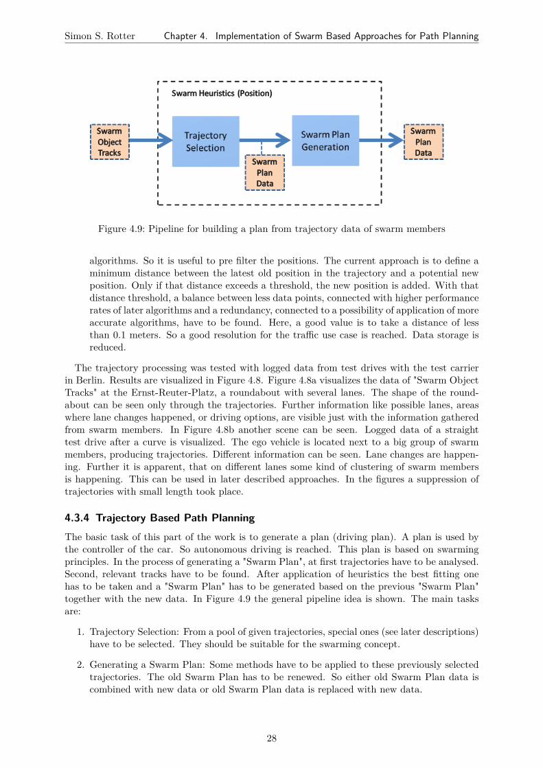
Simon S. Rotter Chapter 4. Implementation of Swarm Based Approaches for Path Planning
Figure 4.9: Pipeline for building a plan from trajectory data of swarm members
algorithms. So it is useful to pre filter the positions. The current approach is to define aminimum distance between the latest old position in the trajectory and a potential newposition. Only if that distance exceeds a threshold, the new position is added. With thatdistance threshold, a balance between less data points, connected with higher performancerates of later algorithms and a redundancy, connected to a possibility of application of moreaccurate algorithms, have to be found. Here, a good value is to take a distance of lessthan 0.1 meters. So a good resolution for the traffic use case is reached. Data storage isreduced.
The trajectory processing was tested with logged data from test drives with the test carrierin Berlin. Results are visualized in Figure 4.8. Figure 4.8a visualizes the data of "Swarm ObjectTracks" at the Ernst-Reuter-Platz, a roundabout with several lanes. The shape of the round-about can be seen only through the trajectories. Further information like possible lanes, areaswhere lane changes happened, or driving options, are visible just with the information gatheredfrom swarm members. In Figure 4.8b another scene can be seen. Logged data of a straighttest drive after a curve is visualized. The ego vehicle is located next to a big group of swarmmembers, producing trajectories. Different information can be seen. Lane changes are happen-ing. Further it is apparent, that on different lanes some kind of clustering of swarm membersis happening. This can be used in later described approaches. In the figures a suppression oftrajectories with small length took place.
4.3.4 Trajectory Based Path PlanningThe basic task of this part of the work is to generate a plan (driving plan). A plan is used bythe controller of the car. So autonomous driving is reached. This plan is based on swarmingprinciples. In the process of generating a "Swarm Plan", at first trajectories have to be analysed.Second, relevant tracks have to be found. After application of heuristics the best fitting onehas to be taken and a "Swarm Plan" has to be generated based on the previous "Swarm Plan"together with the new data. In Figure 4.9 the general pipeline idea is shown. The main tasksare:
1. Trajectory Selection: From a pool of given trajectories, special ones (see later descriptions)have to be selected. They should be suitable for the swarming concept.
2. Generating a Swarm Plan: Some methods have to be applied to these previously selectedtrajectories. The old Swarm Plan has to be renewed. So either old Swarm Plan data iscombined with new data or old Swarm Plan data is replaced with new data.
28

Simon S. Rotter Chapter 4. Implementation of Swarm Based Approaches for Path Planning
Figure 4.10: Selecting trajectories by defining a valid area (green) with an angle in front of theego vehicle. Trajectory 1 is selected because the last point lies inside the valid area.So Trajectory 1 is reachable in terms of the heuristic.
The data about trajectories is given by the swarm member trajectory processing describedbefore (see Section 4.3.3). It contains information about swarm member positions. All together,these are trajectories which indicate used ways in the environment of the ego vehicle. In the firsttask - "Trajectory Selection" - different ideas can be applied. A simple greedy idea is describedand different complexer selection ideas are presented.
"Greedy" Selection of Trajectories
The simplest idea is to select the first trajectory which is found in the environment. With this"greedy" approach a swarm plan is generated as soon as a moving swarm member is detected.But this has some disadvantages. There are cases in which a "greedy" selected trajectory is shortor far away from the ego position. This means inconveniences compared to longer or closer tra-jectories. So selection of shorter trajectories results in more often changes of trajectories. Thisleads in some situations to a chaotic behaviour because of often changes. Further this meansmore often uncertain movements through parts of the environment which have no trajectories.Because areas between trajectory changes are mostly uncovered of swarm trajectories. Thesegaps without information from swarm members have to be bridged by the autonomous car it-self. That gaps occur in the cases of a longer trajectory selection not so often. More distantsuccessive trajectories implicate the same problem with gaps. So farther and consequently moredangerous position changes of the autonomous car are likely with the "greedy" approach. Butthese disadvantages can be solved better if more "intelligence" is put into the selection process.
The application of the greedy approaches is not adequate for real traffic situations. Con-sequently following a trajectory, which is very close to the ego position, is the basic idea foradvanced heuristics. Here different selection ideas are implemented. Different ideas have beenapplied and tested as shown in the following parts. Disadvantages and advantages of differentmethods are explained and a final solution for path planning based on a swarm member trajec-tory selection is given.
Selection of Trajectories by Concerning Reachability
This approach has the property to be more oriented towards a more applicable solution. Com-paring the reachability of trajectories, gives a criterion for a good trajectory in terms of using itas a basis for a swarm plan. If the trajectory is reachable from the current ego position of thecar, the ego car is able to drive onto this trajectory and use it from this position on as its ownplan. To reach this aim a heuristic is used which compares just the last position of the trajec-
29

Simon S. Rotter Chapter 4. Implementation of Swarm Based Approaches for Path Planning
tories of swarm members. If that point is reachable, then the trajectory is reachable (at leastthe last point of it). Through movement of the swarm member, additional positions will followin the future, which are reachable from the current last point, since the last point is currentlythe latest position of the trajectory generating swarm member. So a selected trajectory in thatway gives a good heuristic for finding followable trajectories. To implement these heuristics twomain questions concerning selection have to be answered positive:
1. Lies the last position of the swarm trajectory in a plain in front of the ego car and not inthe back?
2. Lies the last position of the swarm trajectory in a certain area in front of the car. Thiscertain area should be reachable through steering options.
Both question can be solved by applying a simple heuristical idea using angular mathematics:A certain angle is defined. The origin of the angle is located at the current ego position. Fromthis point the angle between two vectors is measured: the vehicle y-axis (corresponds to theforward direction of the ego vehicle) and the vector from the ego position to the last trajectoryposition. Compare the visualisation in Figure 4.10. The swarm trajectory position is reachableif this angle is a very acute angle. Compare the green area in Figure 4.10.
The selection process is now accomplished by iterating over all trajectories and checking ifit is reachable. If the old selected trajectory is still in the pool of reachable trajectories, it isprioritized and it is further used. Else new trajectories are selected by the process. To solve thistask a helper method was defined in Swarm Utilities to reuse that kind of processing.
This is a relative fast method because the last position of a trajectory is quickly retrievable.For each trajectory calculations for one point has to be made. Experiments showed good resultswith acute angles of four degrees. Two degrees to each side of the y-axis. The very acute anglehelps to avoid strong steering. This approach is very inflexible. The very small area is a disad-vantage which can be solved in a better way as described below.
Once having such a toolkit for selecting trajectories it can be further used. If one selectedswarm trajectory is ending, a following trajectory is searched to get a longer plan. For thattask exactly the same method can be applied. Always the last point of the plan is the newreference point for evaluating following trajectories. In that case for the calculation process,the ego position is exchanged with the last position of the last used old swarm trajectory. Thevector in that case is defined by the last point of that trajectory to the last point on the newtrajectory. For the direction not the ego y-axis is used. Instead the alignment of the last part ofthe old trajectory is applied. That is calculable through computing the vector between the lasttwo positions stored in the old selected trajectory. In tests angles of 40 degrees were applied toboth sides to get good results. Successively swarm member trajectories are selected in this way,which are connectible.
Selection of Trajectories by Different "Safety Zones"
Selecting a swarm member trajectory based on the idea above, makes a prioritisation of differenttrajectories difficult because distant endpoints are treated equally. This problem is tackled withthe help of "Safety Zones". A "Safety Zone" is a predefined area in the environment of the car.Trajectories are searched in this area. The usage of these "Safety Zones" leads to a more complexbut more precise selection of trajectories. Reference point of such a zone, is the ego position ofthe car (in the front part of the vehicle). The ego vehicle front direction is the reference direction.
30

Simon S. Rotter Chapter 4. Implementation of Swarm Based Approaches for Path Planning
Figure 4.11: Definition of a "Safety Zone" relative to the ego vehicle position. Through the"Distance" vector the area can be defined at any place in the environment of thecar. Later application puts the "Safety Zone" below the car. Other positions likein front of the car (see figure) are possible. With help of the "Extend" vector therectangular size of the area is defined.
Figure 4.12: Selecting trajectories by investigation of one "Safety Zone" (green) below the car.Trajectory 1 is chosen. Because it has positions inside of the "Safety Zone".
From this reference point on, a "Distance" vector defines the position of the lower left corner ofthe rectangular "Safety Zone". Thus this point can be located at any place of the environmentrelative to the ego car. The left lower corner of the zone is the second reference point. The sizeof the zone is defined with a second vector "Extend". It points from the left lower corner to theright upper corner of the rectangular zone. The definition of a "Safety Zone" is visualized in 4.11.
In the simplest implementation, the safety zone is exactly that area of the environment whichis covered by the shapes of the autonomous car on the ground (see Figure 4.12). A swarmmember trajectory, which contains points at the current ego position of the car, is advantageousif selected. The ego vehicle takes immediately that trajectory for swarm plan generation. It isexpected to be good because of the fact that the car is already at one position of the trajectory(at least one position is lying inside the green "Safety Zone"). It is very safe because no positionchanging manoeuvres have to be made. The already contacted trajectory is continued. Thusthis approach has a very strong safety aspect.
One problem may occur in this context. Only few or no trajectories are selected because ofthe very strict definition of the "Safety Zone" below the ego vehicle. For that case the approachis extended to a more generalized idea: Different zones are defined and evaluations for each zoneare happening after the same idea. Each zone gets a confidence value. Selections are made afterpriority of the different safety zones. So only if no trajectory is found in the zone located directlybelow the car, a search takes place in the next preferable zone and so on. See visualizations inFigure 4.13.
That was implemented and a toolkit for "Safety Zones" evolved which can be defined generi-cally and checked. In that approach degrees of safety can be defined. It is a generic approach.Very "safe" zones can be created. More relaxed zones can be defined for the case no trajectory
31

Simon S. Rotter Chapter 4. Implementation of Swarm Based Approaches for Path Planning
Figure 4.13: Selecting trajectories by using prioritized "Safety Zone"s: Per example three dif-ferent "Safety Zones" are defined. "Safety Zone A" is below the car. Tests for"Safety Zone B" and C are applied, if no trajectory is found in the previous area.In the example Trajectory 2 is chosen because it lies in the closer area B (insteadof Trajectory 1, which lies in area C).
is found in the optimal area. By the described definition with the vectors for "Distance" and"Extend" - see Figure 4.11 - a rectangular "Safety Zone" can be located at any place in the en-vironment of the ego car with any size. This creates a powerful tool for building new heuristicsbased on this concept.
The algorithm is more complex. Dependant on the situation, more calculations have to bemade. In a worst case for all trajectories all positions have to be examined. And further for allof this points all zones have to be checked if the point lies inside. With logged data, at verycrowded situations (e.g. Ernst-Reuter-Platz roundabout in Berlin) the approach with threezones located around the car, still showed real time calculated plans for the autonomous car.
First real-life tests have been made with constellations like in Figure 4.13. Three areas with aincreasing degree of relaxation have been used. Results are convincing. Live test with the testcarrier showed good results. Further more application-oriented heuristics are possible with thedescribed approach. An example is the additional consideration of the trends of trajectories. Inthat case defining "Safety Zones" in the directions of curves have to be made. Complexer zonescan be created through definition of smaller zones of different size which lie close to each other.Sets of zones can be combined for different priorities. Experiments have not been applied insuch far applications, yet.
An application of the different "Safety Zones" takes the different zones (described by the vec-tors for "Distance" and "Extend") and iterates over them as long as either a track is found withinan area or no track can be found. The basic idea can be seen in Algorithm 1. For the checkingif a point lies in a "Safety Zone" a specialized method is used which uses the dot product for xand y direction for efficient checking.
Complexity of the Algorithm 1 depends on the number of "Safety Zones", the number of tra-jectories and the number of stored positions in the trajectories. The algorithm stops as soon asone point is found. As searching takes place from the safest zone to the unsafe zones, this bringsthe best solution. In worst case (e.g. no trajectory in any zone) for each zone all trajectories withall stored positions are checked. Tests in real-life showed still real time Swarm Plan generation.
32

Simon S. Rotter Chapter 4. Implementation of Swarm Based Approaches for Path Planning
Current Safety Zone is the most restrictive one;while not all Safety Zones checked AND no Swarm Member Trajectory for Swarm Planfound do
get vector descriptions for current Safety Zone;// check all Swarm Member Trajectories with current Safety Zone:while not all Trajectories checked AND no Point Found in current Safety Zone do
get current Trajectory;// check all stored Positions in current Trajectorywhile not all Points of Trajectory checked AND no Point Found in current SafetyZone do
get current Point;if current Point in Safety Zone then
set Point Found in current Safety Zone;return current Trajectory for Swarm Plan;
elseendset next Point in Trajectory to current;
endset next Trajectory to current;
endset next Safety Zone to current;
endAlgorithm 1: Trajectory Selection Algorithm: to select usable swarm trajectories by usingdifferent "Safety Zone"s
Trajectory Merging and Plan Generation
For all described heuristics one question is still open. What happens if in the selection processmore swarm member trajectories are relevant? Here further fine granular ideas can be used tofurther prioritize trajectories. Again the first one found can be chosen which is currently imple-mented because of less calculations (timing aspects). But if enough time or calculation poweris available, possible further prioritisation should be done: take the longest trajectory or takethe trajectory with the most far away last position. In both situations it has to be considered,that most trajectories in traffic situations are evolving. So calculations are made on a current"Snap Shot" of the environment and only the "Current Best" can be chosen. Further selectionideas under consideration of more information are explained in the following sections.
One approach for generating Swarm Plans by using "Safety Zone" Heuristics, is described inAlgorithm 2. It is a generic Swarm Plan generation process, which is reusing the old generatedSwarm Plan of the last iteration step. A "Fixed Planning Horizon" is defined. This is a certaindistance in front of the ego vehicle. The current Swarm Plan, up to that distance, is fixedand will not be changed. At that distance, again new swarm member trajectories are searched.Therefore, again the "Safety Zone" Heuristics or others can be applied. If a new last part forthe Swarm Plan is found, a new assembling is done: The old Swarm Plan is cut at the "FixedPlanning Horizon" - only the first part is relevant. The new found trajectory is cut at the closestposition to the "Fixed Planning Horizon", too. But here the last part is relevant. Now bothparts are stuck together and a new actualized Swarm Plan is generated. Consequently, at eachstep dynamic changes in the environment are taken into account to enhance the last part of thecurrent Swarm Plan. This is one advantage of this method. Further the car is not "jumping"around because of harsh Swarm Plan changes. The "Fixed Planning Horizon" keeps a minimumplan constant. This leads to robustness.
33

Simon S. Rotter Chapter 4. Implementation of Swarm Based Approaches for Path Planning
(a) Swarm member trajectories in a round-about for plan generation (Berlin - Ernst-Reuter-Platz)
(b) Generated plan (green) from trajectories ina roundabout based on logged data (Berlin- Ernst-Reuter-Platz)
Figure 4.14: Plan generation based on trajectories of swarm members
if Swarm Plan is not available OR Swarm Plan is not long enough then// take a safe basis swarm trajectory if availablerebuild Swarm Plan (e.g. with one Safety Zone below the car);
else// given Swarm Plan from last step is used and extended:1. find closest point on Swarm Plan to ego position;2. find next point on Swarm Plan in forward direction in planning distance(Reference Point);3. find a swarm trajectory from this Reference Point on, which is most suitable(e.g. use Heuristics with Safety Zones at Reference Point);4. process found trajectory: get last part behind Reference Point(new Swarm Plan part);5. resize old Swarm Plan: Discard part behind Reference Point;6. stick new Swarm Plan part onto the old Swarm Plan at end;7. return;
endAlgorithm 2: Trajectory Selection Algorithm: to select usable swarm trajectories and stickthem together after certain planning distance
As soon as the plan generation is completed the controller of the autonomous car is able touse it. Autonomous driving in the environment is possible. In Figure 4.14 a scene is visualized:A plan (green) was generated on basis of the swarm data.
Solution for the Velocity Matching Problem
For solving the velocity problem described in Section 4.3.2 the processing pipeline (see pipelinein Figure 4.9) was extended. Positions of the observed obstacles, which were used for the swarmdata, are stored. Additionally to their trajectory data, to each position the current velocity vec-tor of that position is stored. The velocity is stored in that way, that it includes the movement
34

Simon S. Rotter Chapter 4. Implementation of Swarm Based Approaches for Path Planning
direction of the vehicle, which was observed at that point. Thus for each observed and usedtrajectory, not only the position is retrievable, also information about the possible speed anddirection at a certain point is available. Consequently the movement direction of each storedpoint is retrievable - trajectories have a given direction. The processing pipeline is in principleas in Figure 4.9. In the application, the swarm based velocity, the autonomous ego car wants,is read out from the stored position. To give back the wanted velocity to the autonomous carhardware it is taken the ego position of the car. For that position the closest point on the se-lected swarm trajectory is searched and the velocity at that point of the swarm member, whichproduced that trajectory is given back to the car’s controller.
4.3.5 Clustering of Swarm Member TrajectoriesMerged information of swarm based data brings further gain. Storing of advanced data andfurther processing through using redundancy is helping for higher approaches. As discussed inChapter 3 one basic advantage of swarms is that the relatively "simple" habit of different agentscan lead to a globally good "complex" habit. Comparable with pheromones from ants, reusedways can be stored. So some kind of higher information about usable ways is stored in this work.
Concerning the data available from the current framework, a swarm approach can bring fur-ther gain if a clustering takes place. That means redundant information is merged and clustered.Thus structures of usable ways evolve during the application of this processing. In this case againthe data of trajectories of objects is taken as a basis. The trajectory of an object can be seenas a sequence of points. Those points were successively reached by that object over some time.Consequently the points and their relations among themselves provide possible driving data:From which point can be reached a certain other point in the environment. Further informationcan be deduced, if additionally more trajectories are available, which are subtending other tra-jectories or which are locally very close to some other trajectories in certain points: This can beseen as general possible connections between different trajectories.
Therefore in the context of clustering, in this work, the above described information, storedin the given trajectories, is extracted and stored in a new data structure (see Figure 4.15 for theschematic idea and Figure 4.16 for the processing pipeline). In Figure 4.15a two possible tra-jectories are shown. They can have its origin from swarm members and they can be perceived.As discussed above a trajectory is represented through reached points in the environment - seeFigure 4.15b. The data points can have different distances, depending on the sensor whichtracked them, the sampling rate and the speed of the objects. In a first extraction phase (seeFigure 4.15c) that points are stored separately - each one in a so called "Way Point". To preservethe information about connections between points, contained in the trajectory, predecessor andsuccessor point relations are stored - shown in the pictures through arrows pointing to the nextneighbouring Way Point. Further information like the speed of the objects that was observed atthis position and an identification number of the trajectory that Way Point belongs to, is stored.In a next step different Way Points are merged in a merging process after certain criterions. Aspatial checking algorithm is used to identify Way Points which are lying close by each other -see Algorithm 3 and Algorithm 4 and explanations below. Possible merges in the example areshown with dotted circles in Figure 4.15d. The two points in the middle (close to the crossingpoint of the two trajectories) are possible candidates for merging because they are of a relativelysmall spatial distance. In Figure 4.15e the output of the merging process is shown - the new"Merged Way Points". The two points in the middle have been merged in one new Merged WayPoint while all other Way Points are building a separate new Merged Way Point. Merged WayPoints store the information of all of their included Way Points. So predecessor and successor
35

Simon S. Rotter Chapter 4. Implementation of Swarm Based Approaches for Path Planning
(a) Two tracked trajectoriesfrom swarm members
(b) Data points of the trajecto-ries
(c) Extracted data point infor-mation - points and pre-decessor, successor relations:Way Points
(d) Possible merge of WayPoints located close by eachother
(e) Way Points located close byeach other are merged withpredecessor and successor re-lations: Merged Way Points
(f) Clustered Merged WayPoints with final predecessorand successor relations:Clusters
Figure 4.15: Schematic idea of the clustering process
relations and trajectory ids are further used. With help of all stored Way Points advancedprocessing is applied. Different merging techniques are used e.g. the mean for the position orvelocity of all containing points is build to find a representative value for the Merged Way Point.
while not all Way Points assigned dotake a not assigned Way Point;if at least one Merged Way Point does exist then
while unchecked Merged Way Points AND current Way Point is not assigned docalculate distance to unchecked current Merged Way Point (e.g. to mean ofMerged Way Point), consider area with lateral and forward distance;mark the unchecked Merged Way Point as checked;if distance is smaller than Threshold then
assign current Way Point to current Merged Way Point;mark current Way Point as assigned;
elsedo nothing;
endend
elsecreate a new Merged Way Point for the current Way Point;
endend
Algorithm 3: Spatial Checking Algorithm
As marked in Algorithm 3 different distance checking methods for the merging process can
36

Simon S. Rotter Chapter 4. Implementation of Swarm Based Approaches for Path Planning
be applied. Through testing with logged data it was found out, that good results are obtainedif a representative value of the Merged Way Point is used. In a first approach the distance ofan unassigned Way Point is calculated to all Way Points of a Merged Way Point. Distancechecking is implemented by testing if one of the points lies in an area defined by lateral andforward extension around the new point. If the distance to one of the Way Points is smallerthan the threshold, the new Way Point is assigned. In certain cases this leads to a blurringeffect. In these cases distances successively become longer. E.g. a Way Point is added whichlies in the threshold distance. In the next step again a Way Point is added which lies in thethreshold distance of the last added point. In this way in worst case in each step the mergingarea is extended by the threshold distance. That leads to bad results - an accumulation offar distributed points. This has the effect of imprecise Merged Way Points. So solutions weresearched to cope with that blurring effect.
Thus the second approach is to calculate a representative value for the Merged Way Pointevery time a new Way Point is added. In the implementation the mean of all current Way Pointsis taken. Distances of new Way Points are checked to that representative mean value. Thatlead to far better and clearer results. This method has still the disadvantage that once assignedWay Points have influence to the Merged Way Point, even if the mean value of the Merged WayPoint is wandering out of an assigning distance (through distant new points) to recently addedWay Points over the time.
Therefore a another method for further improvement is implemented. It works with a precalculation of representative points: D. Guo et al. introduce an algorithm for "Extractingrepresentatives of GPS points" [GLJ10]. In this method a "circular window" is used to find rep-resentative values for data points. An assignment of all data points to that representative pointstakes place. The representative values ("centroids") are pre calculated via a special method (seealgorithm below) which considers unassigned points. The assignment of points to a new "cen-troid" considers already assigned points: It is checked if the new "centroid" fits better. Throughthe related problem an adaptation of the algorithm for the context of the clustering problem ofthis work is implemented - see Algorithm 4:
37

Simon S. Rotter Chapter 4. Implementation of Swarm Based Approaches for Path Planning
for all Way Points wp doif Way Point wp is NOT assigned to any representative centroid then
currentWPsForCentroid;store wp in currentWPsForCentroid;for all Way Points wp2 do
if Way Point wp2 is NOT assigned to any representative centroid thenif Way Point wp2 is close enough to wp (inside euclidean distance) then
store wp2 in currentWPsForCentroid;end
elsedo nothing;
endendcalculate centroid (mean of all positions which are in currentWPsForCentroid);for all Way Points wp3 do
if Way Point wp3 is NOT assigned to any representative centroid thenif Way Point wp3 is close enough to centroid(inside euclidean distance) then
assign wp3 to current representative centroid;end
elsefind representative centroid to which wp3 is assigned to;compare distances of wp3 to old and current representative centroid;if distances is smaller then
delete wp3 from old representative centroid;assign wp3 to current representative centroid;
elseleave current assignment;
endend
endend
endAlgorithm 4: Spatial Checking Algorithm Through Representatives - adaptation of the "Ex-tracting representatives of GPS points" algorithm (see [GLJ10, p. 7 f.]) to the context of thiswork
After building Merged Way Points, in a last step "Clusters" are built. Therefore all MergedWay Points are compared and joined if certain criterions are fulfilled: Merged Way Pointscontain the information about the trajectories they are based on. In a situation in whichdifferent Way Points were inserted into one Merged Way Point, these Merged Way Points storethe trajectory ids of each Way Point. Successive Merged Way Points are stored in one Clusterif they are belonging exactly to the same original trajectories. If at least one trajectory id fromtwo different Merged Way Points is different, then that Merged Way Points are belonging todifferent Clusters. The idea of this constraint is, that a Cluster has only parts of exactly thesame trajectories. A further criterion is that all Merged Way Points in a Cluster have to besuccessive. That means a predecessor or successor relation has to exist between the Merged WayPoints in that way, that a connection from the first Merged Way Point of the Cluster to the lastMerged Way Point of the Cluster (possible via other Merged Way Points of the Cluster) doesexist - if its size is bigger than one. A Cluster consequently stores related information of paths.Thus a Cluster contains information about a drivable structure. In Figure 4.15f the example ofthe two crossing trajectories shows five final Clusters:
38

Simon S. Rotter Chapter 4. Implementation of Swarm Based Approaches for Path Planning
Figure 4.16: Pipeline of the clustering process: Trajectories are refined to "Clusters"
• Four Clusters containing successive Merged Way Points with their fundamental Way Pointsand
• One Cluster with the Merged Way Point of the two basic Way Points in the crossing areaof the trajectories.
A Cluster stores predecessor and successor relations at the Cluster level. Clusters can be mergedaccording to their front and back relations. If two Clusters have a predecessor/ successor re-lation they can be stuck together. That means their original trajectories have a direct spatialconnection to each other. Those paths have more fine granular information than the originaltrajectories. This is because the clustering of different Way Points from different trajectorieswas performed to build the Cluster. And further the connections to other Clusters are stored.So connections between Clusters are usable for further processing. E.g. Clusters are connectablefor a swarm plan generation or for a map generation. The clustering processing pipeline is sum-marized in Figure 4.16. The blue boxes show the different processing steps. The red boxes areshowing different data states of the processing and where the input and output happens. Thetrajectory data of all relevant objects is the basic input and the refined Clusters are the output.
Through the Clustering pipeline a tool is created to refine the "simple" swarm data, which canbe redundant and exhaustive. As input the trajectories of different swarm members comes un-related into the pipeline. The combination of the different data leads to the following advantages:
• Confidence: The clusters in some cases base on one trajectory, but in the other cases theybase on more trajectories. If more vehicles take the same way this means more confidencein terms of a good usable way for the ego vehicle. Additionally the velocities are calculatedmore appropriate because e.g. a mean of all vehicle velocities, which are relevant for theown velocity is built. This is done per Merged Way Point. This information is retrievablefrom the Clusters.
• Degree of Detail: A detailed graph of accessible paths and connections between them isbuilt. The Clusters contain information about different possible ways through the storageof the predecessor/ successor relations. Thus different way options are available.
These advantages of the Clustering idea are usable for different applications. Two applica-tions, which bring gain to the AutoNOMOS Project are explained in the following parts. Avisualization of results of the current implementation can be seen in Figures 4.17, 4.18, and4.19. The underlying road map model (black) is visualized to allow a comparison. In the round-about scenarion (Figure 4.17) the basis red trajectories (see Figure 4.17a) are shown togetherwith the generated Clusters with and without the road map (see Figure 4.17b and 4.17c). TheClusters alone show different traces of the roundabout with possible connections (see Figure
39

Simon S. Rotter Chapter 4. Implementation of Swarm Based Approaches for Path Planning
(a) Captured trajectories (red) of objects in aroundabout scenario with underlying roadmodel
(b) Generated "Clusters" (blue) based on the cap-tured trajectories (red) with underlying roadmodel
(c) Blue "Clusters" and red trajectories withoutunderlying road model
(d) Only blue "Clusters" without underlying roadmodel - drivable parts of tracks are visible
Figure 4.17: Generation of "Clusters" from tracked position data of swarm members with com-parable underlying road model
4.17d). On some positions connections between different roundabout traces can be observed.Here are possible lane changes because a tracked object did a lane change or because Way Pointsof different Clusters are close by each other.
4.3.6 Building a Local Map From Clustered Swarm Member TrajectoriesThe Clusters are used to build a "map", which is used for path planning. The map contains thedata of the current situation in the surroundings of the car and shows driving position and veloc-ity possibilities. From a swarming perspective, many vehicles mean better conditions. The morevehicles are detectable in the environment, the more swarming data is produced, which can beused for further processing. In general traffic scenarios, vehicles are on the streets surroundingthe ego car. In daily situations other vehicles are in front of the ego vehicle. All of these trafficparticipants are used in the clustering process to get information about the environment. Thus,the information is not restricted to only one trajectory or one velocity. Through the suggestedalgorithms, which cluster close by trajectories, this redundancy is processed and stored. So alocal map of the current surroundings of the ego vehicle is built. The latest data is restricted tothe sensor range. But recent stored data gives a map of the whole stored past. So a situationbased map is generated over the time about the observed environment. That map is dependanton the swarm members, which were detected during that time. The current implementation isat the state that the "map" is the set of currently stored Clusters.
Following ideas are not implemented but show how Clusters can be used. The Clusteringproceeding can be used to generate general maps of long-term relevance. First very actual mapscan be generated. A new unknown street can be taken by the autonomous test carrier. Throughthe storing of the cluster based map the information about lanes and speeds can be used forfollowing drives. This information can be stored, extended and updated through new drives atother times on the same street. Applied over different days more redundancy is used. Further ifapplied massively, statistics about streets can be generated. Therefore the processing on differ-ent days and times is applied successively. So on the one hand a more robust map can be built.
40

Simon S. Rotter Chapter 4. Implementation of Swarm Based Approaches for Path Planning
On the other hand very precise maps for different times can be produced via massive redundantdata. For example, a main traffic connection into an industrial area of a city is highly frequentedonly at certain daytimes. At that times congestions may occur and accidents are more likelythan on other day times because of more traffic. Through a time-based statistic that data canbe stored. Pattern recognition can be used to find relations. Local- and time-based maps canbe generated and used for later path planning. Implementations are at the Cluster level andsuch advanced ideas are still open. This was further not tested and is left open for future work.
Further short-term relevance of the map is given. A such generated map is storing all currentsituations. If accidents are happening or road works are taking place, such new dynamic eventslead to changes in the driving possibilities of the environment. Even with pre known static mapsthis cannot be stored in such a time close way. The timespan reaches from seconds (suddenaccidents) to minutes (barriers) and to a few hours (roadworks) and even days (prolongedworks). The cluster based local maps contain that information. So accurate current maps forsuch timespans are available. That maps can be used by the autonomous car itself to make itvery reactive. Further such maps can be propagated to other traffic entities (e.g. C2C). Mappropagation was not part of this work and is left for future work.
4.3.7 Cluster Based Path PlanningThe generated Clusters, described in the last sections, are used for path planning. Clusters givepossible ways through the environment of the autonomous car. These basic ways (Way Points)and their connections (successor and predecessor relations) are stored in the Clusters and areused as a basis for a plan. Further Clusters bring gain to the swarm based path planning becauseof the redundant data.
Through the predecessor / successor relations, information about possible connection betweenthe Clusters are stored. So joining of Clusters is used to generate usable ways. Given one Cluster,a following Cluster has to be found considering some selection criterion. A decision has to bemade, if more than one succeeding Cluster is available. Different Cluster heuristics are appliedin that way. Here different heuristics have been implemented and tested. A description follows:
Longest Successor
A preferable long plan is intended in context of plan generation. The planned autonomousdrive should be long enough to allow a comfortable driving. For that reason the selection ofthe longest possible succeeding cluster is implemented and is called the "Longest Successor"heuristic. To reach that aim, different methods were applied and tested. One approach is tochoose the succeeding Cluster which has the most number of containing Merged Way Points.This is retrievable fast from the Clusters. It has to be read out the size of the set of MergedWay Points in the Cluster. It is mostly right to generate long plans. Another tested approachwhich is cheap in terms of calculation, is to calculate the euclidean distance between start andend point of a Cluster. Then that one with the longest distance is taken. Both approachesshowed similar habits. So that one with less calculation steps is taken for this heuristic - thusthe current implementation prefer the Cluster with most Merged Way Points.
The "Longest Successor" is a heuristic approach because the longest local Cluster does notnecessarily mean that the global generated plan is the longest possible plan. But through thefact that a long Cluster often leads to other long succeeding Clusters it generates long plans.
41

Simon S. Rotter Chapter 4. Implementation of Swarm Based Approaches for Path Planning
(a) Captured traces of swarm members on a straight lane with traces of swarm members (red)
(b) Generated "Clusters" of way points (blue) and their connections together with the swarm data anda road model
(c) Generated "Clusters" of way points (blue) and their connections together with a road model
(d) Only Information of "Clusters" without road model
Figure 4.18: Generating connected "Clusters" from tracked position data of swarm members
42

Simon S. Rotter Chapter 4. Implementation of Swarm Based Approaches for Path Planning
(a) Tracked data of swarmmembers in a roundabout
(b) Tracked data together withgenerated "Clusters"
(c) Generated "Clusters" ofroundabout
Figure 4.19: "Cluster" generation with swarm based data from a roundabout
Most Confident Successor
A plan in autonomous driving context has to be safe. In the swarming context, a path is prefer-able which is taken by more individuals than others. This signalizes safety and confidence. Intraffic context, a lane, which is taken by more vehicles, signalizes to be more manageable thenlanes, which are only taken by less vehicles - in extreme case only one or no vehicle. Here theswarm is an indicator for confidence and safety. Concerning difficult situations like roadworks,or narrow curves this is very helpful to drive in a safe way.
The confidence information is retrievable from the Clusters. Each Cluster stores the ids ofthe trajectories it is based on. Thus a heuristic for a most confident succeeding Cluster is totake that succeeding Cluster, which has the most stored distinct trajectory ids. More trajectoryids are representing a way, which is used by more swarm members which were driving at thatpositions and their Way Points were merged.
The "Most Confident Successor" is also only a heuristic because the stored number of basedtrajectory ids differs in special situations e.g. when occlusion appears. Further a swarm is wrongin some situations. Because of limited sight in some situations the most swarm members take amore difficult lane than others. But in most situations the heuristic is right. In tested situationsthis heuristic showed good results.
Minimal Direction Change Successor
A problem of driving plans are lane changes and in general not continuing the driving habitrespectively harsh interruptions of the driving continuity. An approach is to keep the changeof direction of the driving plan as small as possible. This heuristic selects succeeding clustersafter this criterion. The driving direction of the last point in the current cluster is taken. Thenthe absolute value of the deviation from this direction to the direction of the last points of thesucceeding clusters is calculated. The cluster which has the smallest absolute deviation in itslast point is taken as the succeeding Cluster.
The "Minimal Direction Change Successor" is a heuristic selection because deviation of direc-tion of the last cluster point depends in some cases on the size of the cluster: Clusters with longdistances in some situations have more curved parts than shorter Clusters. So the success ofthe heuristic depends on the size and the curve habit of the Cluster. The heuristic showed goodresults in tests with the simulator.
43

Simon S. Rotter Chapter 4. Implementation of Swarm Based Approaches for Path Planning
Figure 4.20: Smoothed swarm based plan, based on swarming data (Cluster based with selectionof most confidence)
Advanced Heuristics
The implemented heuristics give a basic solution for swarm behaviour for path planning. Tra-jectory based heuristics can be used for accurate path planning. Further the Cluster basedheuristics are usable for advanced path planning. These ideas can be extended, combined andfurther improved to advanced heuristics as described in Chapter 6.
4.3.8 Smoothing the Swarm Plan DataFurther action has to be done to generate smooth driving plans for the autonomous car. CurrentSwarm Plan Data is based on many different points. Either these points are positions, which areextracted from trajectories. Or these points are positions stored in clusters. In both cases theyare originally from sensors which produce many points in small distances to each other. Re-spectively imprecision of the sensors and produced outlier points, this leads to a current SwarmPlan Data state which is not usable to generate smooth driving plans.
In that context, redundancy of data points is a positive aspect. This is exploited in a smoothen-ing way. Through inaccuracy around real positions, the redundant data together gives a goodapproximation for the real positions in a trajectory. Smoothening is reached with help of linearregression. Position data points of a part of the Swarm Plan Data is taken. Then a model forthat part is created with linear regression methodology. The model is used to sample all pointsof the taken part and get corresponding values from the model. These values are smooth becausethey are basing on a polynomial. The values are further used for generation of a smooth drivingplan. Furthermore an algorithm is applied which uses redundant data to delete outliers forsmoothing the driving data. Here an adaptation of the RANSAC method with linear regressionwas used (see [FB81] and application of the RANSAC method in the project [Zei13]).
One problem arises in that context. To get an usable model for linear regression the datapoints have to be in a coordinate system in that way, that no clustering of most points at smallx-value distances is happening. This means, in an extreme case all y-values are located alongone x-value. For a good model a distribution along the x-axis is needed. The Swarm Plan Datais appearing along the road. All data points in the project are given in a world coordinate
44

Simon S. Rotter Chapter 4. Implementation of Swarm Based Approaches for Path Planning
system, so different from the car perspective. Through the fact that a road can run along they-axis direction of the world coordinate system, exactly that problem occurs. All y-values of thedata points are clustered along x-values of small deviation. In such a case a good polynomialapproximation to the data points is not possible. To cope with this problem a transformationof all relevant points into the car coordinate system is done. This helps because the car’s direc-tion in general is going into the direction of the street (at least a few meters). Further curvescan happen, but even concerning a 90 degree curve, some distance is between the coordinateorigin at the car’s position and the data points which are distributed in 90 degree to the carsdirection. Further if the car is following the course of the curve that problem is disappearingthe closer it comes to the problematical data points. So this method helps to get at least inthe immediate surrounding of the car data points in a representation which helps to create anusable linear regression model. And through the fact that the car is following the direction of thestreet an always latest transformation into the car coordinate system is keeping this constraintfor the immediate surroundings of the car upright. Transformations in the implementation aredone with help of a affine transformation and with help of the C++ library "Eigen" (see [Eig14]).
After the transformation of the data points into the car coordinate system is done, the linearregression model is built. Here a method was implemented to test different degrees for the usedpolynomials. For the described small distances (because of possible narrow curves) polynomialsof degree two or degree three are good applicable. With help of the model a sampling in therelevant area for which the model was created is done. The new data points, based on thesampling with the model, have to be re-transformed into the world coordinate system. This isdone with the inverse matrix from the first transformation.
In Figure 4.20 the resulting driving plan based on the smoothing with linear regression isvisualized with help of the simulator. The basic heuristic for swarm plan generation is basedon the clustering method with a merging size of 2 meters into the front and 3 lateral meters.The succeeding cluster selection is based on the most confidence criterion - means the clusterwhich has most basic trajectory ids. The linear regression model is based on a polynomial ofthird degree. A sample rate of four meters was applied on the model. Additionally for localplan generation only the closest data points in a distance of a maximum of 60 meters to thefront and the back of the car were considered. This lead to a consideration of data points in arange in which a good approximation via a polynomial of third degree is possible. Further thesuccessive consideration of the area behind the car leads to a smoother application of the planfor driving. Jumping plan positions below the car are avoided. In that way, old data pointswhich influenced the current plan have impact on the plan generation of the current situation.
4.3.9 Interface to the Controller ModuleThe planned positions and velocities have to be handed over to the car’s hardware. Thereforethe basic tasks and pipeline of Figure 4.21 is applied. The dotted black line is signalizing theinterface to the existing project modules which are abstracting from the vehicle hardware. Basicideas for planned positions and velocities are described in the following.
To apply the wanted swarm based plan, generated by the heuristics, to the autonomous carhardware, a communication between the swarming modules and the car controller is needed.Plan data contain that information which is used by the car’s controller to reach positionswith velocities. So the main data is a sequence of positions and corresponding directions (analignment of the car). Further in the swarming context, wanted velocities at certain points arerelevant. So a new data structure for managing all of this relevant data is used. It furtherprovides specialized methods to manage the swarm plan data. Methods for adding new data
45

Simon S. Rotter Chapter 4. Implementation of Swarm Based Approaches for Path Planning
Figure 4.21: Pipeline for building a plan from Swarm Plan Data and handing it over to the vehiclecontroller. The interface to the next abstraction level is marked by the dotted blackline. Once a special plan for the vehicle controller is generated. Second the velocityis extracted. Both is handed over.
or integrating new planned data into an old existing plan (new planned parts of the plan) areprovided.
To get the autonomous car to drive to the planned points, generated by the heuristic imple-mentations, a communication between the swarm modules and the hardware is needed. Herethe fundamentals of the current project were useful because the communication to the controllercan run via a given data type which is sent over a module connection. The new data structureprovides a method which generates data for the controller and hands it over. The controller isresponsible for calculating parameters to reach the plan.
Additionally the velocity calculated via the velocity matching is given to the controller viaa new module connection which was established. So parallel to the position data a way wasimplemented to get the controller to try to obtain a wanted speed. This is sent in real time.Therefore the work of the velocity matching was used, which stored a wanted speed for everyposition of a planned trajectory (see Section 4.3.2). For each step for getting a wanted speed outof the stored planned Swarm Plan Data, the following idea is applied: The closest point on theplanned trajectory to the current position of the ego car is searched. Therefore the euclideandistance is taken. Then the stored velocity of that point is used. It is sent via the established newmodule connection to the controller of the vehicle. The controller tries to obtain this velocitywith respect to safety aspects (centrifugal accelerations, obstacles, etc.).
46

5 Evaluation - Experiments and Tests
5.1 Test CasesDifferent aspects for test cases are interesting in the context of this work. The general idea isto evaluate the approaches of this work. Two different general kinds of tests were applied:
• Evaluations based on the simulator of the project
• Evaluations based on test drives with the autonomous test carrier of the project
These tests are described in the following sections. Different ways of generating driving plansfor the autonomous car are introduced in this work. The best heuristics (trajectory based pathplanning with angle, "Safety Zones" and Cluster based path planning) were used in tests withthe simulator to compare their success rates after special criterion. Therefore different standardtraffic situations were selected. First, it is important to be able to generate swarm based planson straight areas. Second, curves on streets have to be managed. And third a combination ofboth: A roundabout traffic scenario. Here straight parts (e.g. at the exit) are combined withcurvy parts.
The tests in the simulator were applied with logged data. The behaviour of a simulatedautonomous car with the swarm behaviour module was observed. All situations were testedwith logged data, stored from real traffic. In all situations swarm members were available.Heuristics are compared with help of the roundabout scenario as it represents a combinationof the different situations. The simulator from the existing project was used for accomplishment.
Further it is important to evaluate, if the swarming approach is applicable in real-life scenarios.Therefore an experiment with the test carrier (introduced in Section 2.1.2) in combination withreal traffic participating cars in a test area is designated. Here the general applicability of theSwarm Behaviour module is evaluated against real sensor input and real hardware output.
5.2 Evaluation of Different Heuristics in the SimulatorAn evaluation was carried out with help of the simulator of the project. Success between thedifferent heuristics was measured. The object of comparison is a driving plan. The general ideabehind all approaches is to be able to generate a plan which is sent to the autonomous car’shardware. Consequently the generated plan directly effects the behaviour of the autonomouscar. So it affects the quality of autonomous driving. Thus the generated plan of the differentapproaches is compared (also see ideas in [Wan12] Chapter five for evaluating plans). Differentaspects have been taken into account as a criterion for a good plan:
1. Length and continuity: The possibility to drive through a certain traffic situation withoutstopping. A stop is connected with a replanning or an intervention of the safety driver. Astop is connected with a plan of smaller length. The longer a autonomous drive, based ona plan, without intervention of the safety driver is, the better is the plan.
47

Simon S. Rotter Chapter 5. Evaluation - Experiments and Tests
Figure 5.1: Evaluation in roundabout scenario in the simulator of the project. A generatedexample plan is visualized in green and red.
2. Small number of changes of continuity: If the plan makes relatively sharp curves whichare not necessary. Comparable with a lane change in a situation were the current lane isgood and has not be changed.
As a basic traffic situations which covers all difficulties which were discussed in this work(straight lanes, curves, and combinations of both cases) a roundabout is used. In Figure 5.1 theused scene in the simulator is visualized. The evaluation measurements start from the positionof the beginning of the green line (Point A) at the left side till the number 17 at the end of theroundabout (Point B). Logged data from a live test drive with the test carrier was taken forthe scenario. The data is from the Ernst-Reuter-Platz Roundabout in Berlin and was logged atdate 14.11.2013. That data was applied with the simulator. The input form the logged data wastaken by the "Swarm Behaviour Module". It was processed. Plans and velocities were generatedby the "Swarm Behaviour Module". The plans were forwarded to the simulator. The simulatorof the project used a such created plan to steer a virtual car with the simulated behaviour of thereal test carriers hardware. Plans and a road map were visualized. This visualization was usedas a basis for the above described evaluation points. Each lane change of the plan was penalizedwith one point - in the example in Figure 5.1 in the considered segment three lane changes arevisualized. This equals three penalty points. Further a replanning and a replacement of thecar in the simulated environment was penalized with one point. A replanning was carried out,when the simulated car was not continuing with driving, but the tested scenario segment wasnot driven off. When replanning was not helping to continue the drive, an replacement of thecar was done in the simulator. This also counted one penalty point. In real both, replanning andreplacement means, an intervention of the safety driver is necessary to continue the drive. Foreach started test a replacement to the start position of the scenario segment and a replanningwas carried out to start planning from comparable positions. This is equally counted for allheuristics with one penalty point for replacement and one penalty point for replanning. Threedifferent lanes were used as a starting point for each heuristic. So an evaluation for data withdifferent frequented lanes was carried out. Success is measured with the sum of penalty points.An approach is more successful than another one, if its sum is smaller than the sum of the otherapproach. Less penalty points equals a better plan. In Figure 5.1 the referencing numbers ofthe lanes are visualized on the left side. The inner roundabout lane is number 1, the middlenumber 2 and the outer roundabout lane is lane number 3. The Tables 5.1 till 5.6 show thecounted evaluation of this scenario.
In the following the different evaluated heuristics are specified in more detail. The term "lane"is used in the following for comparability. In the swarming context driving can be considereddetached from marked lanes on the road. Nevertheless lanes are suited as a measure for com-parison and as a fundamental term for discussion. As discussed before the greedy approach
48

Simon S. Rotter Chapter 5. Evaluation - Experiments and Tests
Different lanes 1 2 3=========
Different CriterionsNumber of Replacements 4 5 2Number of Replannings 4 4 2Number of Lane Changes 4 4 5
Table 5.1: Evaluation of the "Angle Based Trajectory Selection" heuristic
Different lanes 1 2 3=========
Different CriterionsNumber of Replacements 3 1 2Number of Replannings 1 1 2Number of Lane Changes 1 0 1
Table 5.2: Evaluation of the "Trajectory Selection by Safety Zone Below the Ego Vehicle" heuris-tic
of trajectory selection is not further used. Because it showed no applicability in daily trafficsituations. So it is not appearing in the following evaluation.
Angle Based Trajectory Selection:
As described in Section 4.3.4 - "Selection of Trajectories by Concerning Reachability" an anglebased checking of trajectories is applied. An opening angle of four degrees in the y-direction ofthe vehicle is used. As depicted in Table 5.1 compared to other approaches many replannings,replacements and lane changes happened. One main problem of the approach is to find an initialtrajectory in a curvy area. Further, as soon as the ego vehicle is driving a curve the referencechecking area defined by the angle in forward direction is looking to side lanes. This results inlane changes, if other trajectories are discovered in these areas. Or a stopping of the car if notrajectories were in that area. Through curves this happens often and declares the high penaltyvalues.
Trajectory Selection by Safety Zone Below the Ego Vehicle:
This heuristic selects trajectories by considering a defined area below the car - see explanationsin Section 4.3.4 - "Selection of Trajectories by Different ’Safety Zones’". In the tests, in somecases, no trajectories can be found for selection. This is explainable through the very precisedefinition of the area below the car. It is a very strict definition and if no trajectory data ofswarm members is available for this area, an intervention by replacement and replanning has tobe done - see values in Table 5.2. This is the cost of the "safety" of this method. Otherwise,few lane changes are happening. The fact that a once taken trajectory (which already is locatedbelow the car) is followed to the end, leads to the consequence, that a realistic (human like)drive is happening. So less lane changes according to the drive of the selected trajectory isperformed. Best results are achieved by initially taking the middle lane (number 2). That is thelocation were most vehicles produced trajectories. Consequently an ending trajectory is morelikely located to other close by located trajectories than this is the case on other lanes. In thatcase no further replanning and replacements (except the initial ones) has to be made.
49

Simon S. Rotter Chapter 5. Evaluation - Experiments and Tests
Different lanes 1 2 3=========
Different CriterionsNumber of Replacements 1 1 3Number of Replannings 1 1 1Number of Lane Changes 1 1 0
Table 5.3: Evaluation of the "Trajectory Selection by Three Safety Zones in the Ego VehicleArea" heuristic
Different lanes 1 2 3=========
Different CriterionsNumber of Replacements 1 1 1Number of Replannings 1 1 1Number of Lane Changes 1 2 2
Table 5.4: Evaluation of the "Closest Cluster - Longest Successor" heuristic
Trajectory Selection by Three Safety Zones in the Ego Vehicle Area:
In this heuristic again "Safety Zones" are applied - see explanations in Section 4.3.4 - "Selectionof Trajectories by Different ’Safety Zones’". Here not only one area below the car is defined.Three areas are used: The first "Safety Zone" is defined exactly below the car. It is comparableto the heuristics described before and represents the "safest" zone. The second "safest" zone isan extension of that area to each side. This means that the lateral respectively the forwardand backward boundaries of that zone is at distances of about double distance to the ego carposition than the boundaries of the first zone. A third zone is defined in the front of the carand afterwards to the front of both other zones. This is the "unsafest" defined zone because itlies in a farther distance than the other zones. But still it covers an reachable are, because itis in some distance to the front of the car. With that application of the "Safety Zones" resultsare as depicted in Table 5.3. Again comparable good results for lane changes were reached.Here the explanation is as above for the usage of one zone. Once selected a good trajectoryand followed, this is comparable to a human drive related to less lane changes. Further, betterresults, concerning replanning and replacement, were reached than in the "Trajectory Selectionby Safety Zone Below the Ego Vehicle" heuristic. This is explainable through the more relaxeddefinition of further "unsafer" zones which are applied if no appropriate trajectory could befound in the safest zone. So a way is described how to define better trajectory selection basedheuristics with the usage of zones: A fine enough arrangement of the number and positions ofthe "Safety Zones" have to be applied.
Closest Cluster - Longest Successor:
This cluster based heuristic showed relatively good results in the test scenario - compare table5.4. In Section 4.3.7 the "Longest Successor" heuristics was introduced. The closest cluster tothe ego position is initial selected. Succeeding Clusters are distinguished by length. The longestis taken as successor. In all cases good results were reached. After starting no replanning andno replacement - so no intervention of the safety driver - has to be done. Few lane changes arehappening. This is explainable through the kind of selection: If a longer cluster was detected ona close by lane then this is preferred. Through following long clusters, only fewer opportunitiesfor changes are existing.
50

Simon S. Rotter Chapter 5. Evaluation - Experiments and Tests
Different lanes 1 2 3=========
Different CriterionsNumber of Replacements 1 1 1Number of Replannings 1 1 1Number of Lane Changes 1 1 1
Table 5.5: Evaluation of the "Closest Cluster - Most Confident Successor" heuristic
Different lanes 1 2 3=========
Different CriterionsNumber of Replacements 1 1 1Number of Replannings 1 1 1Number of Lane Changes 1 0 0
Table 5.6: Evaluation of the "Closest Cluster - Minimal Direction Change Successor" heuristic
Closest Cluster - Most Confident Successor:
The cluster based heuristic, which is selecting the most confident successor, even showed betterresults (see 5.5 in the scenario. Again, once taken the closest cluster no replanning and noreplacement has to be done. This time less lane changes happened than in the test before.This is explainable through the definition of confidence in this context. Always the succeedingCluster which represents most trajectories is taken. Once found such a Cluster it is probablethat following clusters with most confidence are at the same lane. In the roundabout scenariothe second lane (middle one) is highly frequented. So once taken a Cluster which leads to thatlane, it can be stayed on it and continued. Thus in the current consideration the most confidenceheuristic idea is evaluated as very good usable for daily traffic situations.
Closest Cluster - Minimal Direction Change Successor:
The cluster based heuristic selecting succeeding Clusters, which have the minimal directionchange, showed very few lane changes and no need for intervention. In the results of the testshown in Table 5.6 only one lane change was carried out if started on the inner lane of theroundabout scenario. The explanation is that the direction change of Clusters of other lanes areso different from the direction change from the current Cluster that concerning this heuristic itis mostly better to stay on the lane of the current Cluster and take a following Cluster on thatlane.
Comparison of Different Applied Heuristics
A comparison of the different results from the test is depicted in Table 5.7. The results of thedifferent heuristics of the previous evaluation tables are taken. Per lane the sum of the penaltypoints in the tests are listed. The result column is showing the sum of all penalty points perheuristic in all tests. Angle based trajectory selections has a very high penalty sum. So thisapproach is compared to the other approaches very weak. Cluster based selection approacheshave best results (small penalty sums). Future work should focus on that ideas. Further theapplication of different "Safety Zones" show good results. Approaches should lead to a finerdefinition of "Safety Zones" if a clustering is not trusted and a exact following of trajectories isrequired.
51

Simon S. Rotter Chapter 5. Evaluation - Experiments and Tests
Different test 1 2 3 Result========= (Sum)
Different HeuristicsAngle Based Trajectory Selection 12 13 9 34
Trajectory Selection by Safety Zone Below the Ego Vehicle 5 2 5 12Trajectory Selection by Three Safety Zones (Ego Vehicle Area) 3 3 4 10
Closest Cluster - Longest Successor 3 4 4 11Closest Cluster - Most Confident Successor 3 3 3 9
Closest Cluster - Minimal Direction Change Successor 3 2 2 7
Table 5.7: Comparision of the different heuristics - per lane sum of points from evaluations andresult (sum of points over all lanes)
5.3 Evaluation of the Clustering of Swarm Member TrajectoriesClustering of Swarm Member Trajectories is usable to generate a Possible driving map. Thismap can be used for path planning. To evaluate the generated clusters in a map context, loggeddata were used. For this a test drive with the test carrier was logged. The logged data of theobstacles were stored together with its GPS data. This was usable to match map data withthe obstacle data and the data of the clustering output. Data from a roundabout in Berlinwas used: The Ernst-Reuter-Platz. In Figures 5.2 and 5.3 the results are visualized. A goodapproximation of the different lanes of the Ernst-Reuter-Platz roundabout is reached.
To show the different steps of the clustering process compared to a map, in Figure 5.2a thelogged data is visualized. The red lines are the trajectories of tracked obstacles. Under the datathe GPS matched data of the map is shown. So the part of the Ernst-Reuter-Platz in Berlin isin the figure. In the second Figure 5.2b the output of the clustering module is shown togetherwith the basic logged obstacle trajectory data. The last Figure 5.2c shows the generated clustersalone. They are matching the lanes of the roundabout in most areas. It has to be consideredthat the clusters were generated based on the current situation of the logging process. So thislanes which are seen are showing a kind of "snap shot" of that situation, how the lanes (definedby the swarm members) were located at that time. If no traffic participants were at that timeat a certain lane, that lane is not detected. It can be seen that a good approximation of thebasic lanes of the Ernst-Reuter-Platz are taking place. On some parts are lane changes. Basedon the matching of GPS data of the Cluster positions and the map data, a good result can beseen. The visualized results are based on the clustering process which uses a merging area withforward and lateral area definition. For comparison, Figure 5.3 has to be considered. Here theimplementation of the described adaptation of the "Extracting representatives of GPS points"[GLJ10] method was used.
First using the method described in Section 4.3.5 was applied with using a continuously adop-tion of the representative value each time a point is added to a Merged Way Point. Here amerging distance of seven meters in forward direction and three meters of a total lateral dis-tance (a bit less than a lane width) showed good results (compare Figure 5.2). So the lanes of atraffic scene were re-creatable by using the swarm based trajectory data. By using a very highlateral distance for merging (e.g. ten to 15 meters of total lateral distance and forward distancesof about 6 meters) a good approximation of the middle of the street was obtained. Through thedistinction between forward and lateral merging distances this was possible and showed good
52

Simon S. Rotter Chapter 5. Evaluation - Experiments and Tests
(a) Raw tracked data of swarm members
(b) Raw tracked data of swarm members and generated "Clusters"
(c) "Clusters" generated from the tracked swarm data
Figure 5.2: Evaluation of the Clustering Process: Generated "Clusters" based on swarm data atthe Ernst-Reuter-Platz in Berlin
53

Simon S. Rotter Chapter 5. Evaluation - Experiments and Tests
Figure 5.3: "Clusters" generated from the tracked swarm data using the described adaptation ofthe "Extracting representatives of GPS points" method from [GLJ10]
(a) Application of a merging of Way Points witha lateral and forward defined area for buildingClusters
(b) Application of a merging of Way Pointswith an adaptation of the "Extracting rep-resentatives of GPS points" method from[GLJ10] with a "circular window"
Figure 5.4: Approximating the course of the road with different methods and high merging values
results - compare 5.4a. This method can be used if a general course of the road is wanted to beextracted from swarm data.
With the adopted method based on the approach of D. Guo et al. "Extracting representativesof GPS points" [GLJ10] good results were reached with application of a "circular window" of asize of 1.8 till 2.2 meters (radius) to extract relevant lanes. It showed better and clearer resultsthan the previous method in cases of overlapping trajectories - see 5.3. This is explainablethrough the more precise selection idea of representative points. Points are assigned in a clearerway to get Merged Way Points in this method. An application of this method with a high value(six to ten meters) for the "circular window" showed relatively good approximations for the gen-eral course of the road - compare 5.4b. Nevertheless some inaccuracy at points in curves wereobservable. The other method showed better result in terms of accuracy but also some noise(parallel close by lane parts) was detected. Both is explainable through the distinction betweenforward and lateral merging distances in the above method compared to the "circular window"of the current method. It is left open for future work to combine both ideas and evaluate anapplication of forward and lateral distances to the second method.
54

Simon S. Rotter Chapter 5. Evaluation - Experiments and Tests
(a) Test area Tempelhofer Feld (b) Test area Tempelhofer Feld with test carrier
Figure 5.5: Testarea - Tempelhofer Feld in Berlin - area, obstacles and test carrier
5.4 Live Experiments with the Test CarrierDuring development of the Swarm Behaviour Module in addition to tests with logged data inthe simulator as well testing in real life took place. The special test area Tempelhofer Feld wasused for this purpose. The autonomous test carrier of the project (see Section 2.1.2) was usedas the autonomous ego vehicle. The test area is a big field with obstacles. Some areas have lanemarkings. So suitable to simulate traffic scenarios. Other vehicles were used to get data aboutobstacles and possible swarm members. The test area can be seen in the pictures of Figure 5.5.Different experiments were carried out to simulate real traffic situations were the implementedswarming approaches were applied. Tests were performed till speeds of 30 km/h. Failures andunexpected habits of the implemented software were discovered during the tests. This was usedfor improvements through out the development of this work. Different implemented develop-ments are basing on the insights of the live tests. E.g. improvements of the swarm based planlike smoothing before handing it over to the vehicle controller. Further a range of improvementswere done to stabilize the habit of the software and reaching a good maintainability.
Different test scenarios with swarm members were performed. In the simplest test configura-tion the autonomous test carrier was located behind one other car - the leading vehicle. Theleading car performed different driving manoeuvres. The test carrier should detect the leadingcar, and percept all of its relevant values: the trajectory (positions) and velocities with directionat this positions. Additionally with the current ego state this was the input into the swarmmodule as described in the previous Chapter. Swarm algorithms were performed and the testcarrier followed the leading car. The different manoeuvres included straight drives, averagecurves and sharp curves. Accelerations and brake applications were tested.
In further test scenarios two vehicles were used as swarm members. In one case both ve-hicle started in front of the ego car. Again the autonomous car had to perceive the relevantswarm information. The swarm behaviour was performed and the habit of the ego vehicle wasobserved in the situations of straight drives, curves and speed differences. A good performancewas accomplished. In a further case the two swarm member cars were performing manoeuvresin a more unpredictable way. So their trajectories were crossing over. Occlusions of the carshappened. So parts of the trajectories were vanishing for the ego vehicle’s point of view. Soonly one trajectory was usable. In this case again a good swarm behaviour was observed. Ina third case at the beginning only one car was detectable as a swarm member. A second carwas appearing after some time, overtook the ego car and provided swarm data which was asgood as the first swarm member’s data. Again in this tests good swarming results were observed.
55

Simon S. Rotter Chapter 5. Evaluation - Experiments and Tests
Further a test was accomplished to find out how accurate the autonomous car can followanother leading car. Therefore a test lane was used with several curves and straight parts. Theleading car was accelerating at different positions. The autonomous car was following the lead-ing car and was keeping the velocities of the leading car at the appropriate positions. Throughthe lane markings the accuracy of the actual reached positions of the autonomous car werecomparable. The result was very good. A good swarm based driving performance over a largerdistance (several straight and several curvy parts with a roundabout similar situation at theend) was achieved. Velocity and positions were accurate. Thus the swarm based autonomousdriving with the implemented approaches in the tested traffic situation is evaluated as possible.
56

6 Conclusion and Future Work
6.1 ConclusionSwarm behaviour for path planning is object of this thesis. With this work swarm based ap-proaches for path planning are implemented. To get a context to the topic, an introductionto swarm based ideas is given. The AutoNOMOS Project is introduced. Further, a transferof swarming ideas to the autonomous driving context is discussed. Implementations with focuson the topics swarm member selection, velocity matching, processing of swarm member trajec-tories, trajectory based path planning, further processing of swarm member trajectories to getabstracted Clusters, path planning based on Clusters, smoothing of a swarm based plan andhanding the processed swarm based plan to the vehicle controller are described and discussed.
With the usage of this approach it is not only possible to generate better autonomous driv-ing solutions in unknown or dynamic areas. It is also usable to generate better street mapsconcerning current situations like roadworks, if swarm data is available. These maps are fur-ther usable for autonomous path planning. So this work helps to bypass limitations in currentapproaches for the map based planning of driving through swarm approaches. It also suggestsan improvement to generate maps appropriate to current situations. These maps are basis forfurther swarm based path planning. Advanced implementations around this topic are still open.Implementations are at the state of Clusters and Cluster based heuristics. In the following adetailed explanation of the fulfilled requirements of Table 1.1 is given:
REQ01 Swarm Based Extension of Current Software Solution
Throughout Chapter 4, a description of the implementations of this work is given. It describesthe software which was developed in this work. Swarm based ideas are introduced - see Chapter1 and Chapter 3 - and the current AutoNOMOS Project is described - see Chapter 2. Swarmbased ideas are further used as basis for implementations. A basic idea is given how to integrateswarm based ideas into the current state of the software of the AutoNOMOS Project. First aswarm member selection is introduced. Further different applications and their implementationsof swarm member based trajectories are described. So swarm based path planning is possible.Further an abstraction of swarm based trajectory data is introduced - the Clusters. An descrip-tion is given how these Clusters can be used for swarm based maps which are a foundation foradvanced swarm based path planning. Different heuristics and their implementation for suchswarm based path planning are given. With the smoothing of the swarm based plan and theimplemented connection to the vehicle controller of the current AutoNOMOS Project an integra-tion of swarm based driving plans is given. Thus a swarm based autonomous driving is possible.Consequently a swarm based extension of the current software solution for the autonomous testcarrier is reached.
REQ02 Swarm Based Ideas
A transfer of swarm based ideas towards traffic is given at different parts of the work. Allimplementations and described ideas were examined under the consideration of swarms. Thusin a traffic situation swarm members are extracted. Therefore moving obstacles are consid-ered. They are considered as swarm members, which are giving valuable information for the
57
Simon S. Rotter Chapter 6. Conclusion and Future Work
ego autonomous car. With help of their trajectories swarm based data is given. That is funda-mental for implemented algorithms and data structures. Implementations allow a swarm basedautonomous driving. Consequently this aim is reached.
REQ03 Implementation of Swarm Based Algorithms
In Chapter 4 implemented ideas are described. Processing pipelines are given to reach a swarmbased behaviour of the autonomous car. Implementations start with object detection and swarmmember selection in the context of traffic and the autonomous vehicle. Velocity matching is im-plemented and described. Implemented ideas of the processing of trajectories of swarm membersare described. Further the different ideas of a swarm trajectory based path planning are given:a greedy approach, a more advanced approach working with a reachability area, and well suitedapproaches with "Safety Zones" with algorithmic described ideas. Further algorithms for a clus-tering of the swarm data is given. Different implemented ideas are described using differentideas to merge data. Different implemented heuristics for swarm Cluster based path planningare given: "Longest Successor", "Most Confident Successor" and "Minimal Direction ChangeSuccessor". With further described implementations an autonomous driving with that swarmbased algorithms is realized.
REQ04 Implementation of Swarm Based Data Structures
Throughout the work different implemented data structures are mentioned. They were necessaryto reach the swarm based autonomous driving. Besides the algorithms described before that isnecessary to maintain and store current data. So data structures like "Swarm Object Tracks"and the data structure of "Clusters" which contains "Merged Way Points" and "Way Points" areimplemented. Further a data structure for managing "Swarm Objects" with "Swarm Members","Swarm Static Obstacles" and "Swarm Unclassified Obstacles" and a data structure for a "SwarmBased Plan"s are implemented.
REQ05 Embed Software into Current Project
Section 4.1 gives a basic idea how the "Swarm Behaviour Module" can be integrated into thecurrent architecture. See especially Figure 4.2. Detailed names of the used existing projectmodules and connections are given. Further Section 4.2 gives a more detailed idea, which existingproject modules are connected with which processing swarm tasks as input. And further howthe processing is applied to generate the output which is given to the vehicle controller module ofthe existing project. See the Figure 4.3, describing the general architecture with its connectionsto the existing project. In more detail in Section 4.3.1 and Figure 4.4 and further in Section4.3.3 and Figure 4.7 the input interfaces are described and how data of the existing project isused for further processing in this work. The output data of the "Swarm Behaviour Module"is given to the vehicle controller of the autonomous car. This implementation and interface isdescribed in Section 4.3.9 and visualized in Figure 4.21. To make a drivable swarm based planpossible, a smoothing of the generated driving plan is integrated - see Section 4.3.8.
REQ06 Integrate Data of Current Project Modules
As described under REQ05 the interfaces to the existing implementations of the AutoNOMOSProject are implemented and described. In this way, the input data of the existing module"Obstacle Fusion" is used to get data about potential swarm members. Further existing modulesproviding data about the current ego state are used. All processing of this work is based on thisdata. So REQ06 is fulfilled.
58

Simon S. Rotter Chapter 6. Conclusion and Future Work
REQ07 Simulation Tests
Throughout the work testing was done. Therefore the simulator of the project was used. Theautonomous car was simulated. Input data was given to the "Swarm Behaviour Module", process-ing was done and output was generated for the simulated hardware. Observation of the habitsof the "Swarm Behaviour Module" was done through the simulator. For detail see Chapter 5.
REQ08 Visualization
A visualization of data is done. This is done with help of the simulator. Swarm Members, theirtrajectories and generated swarm based driving plans are visualized. Further the generatedClusters are visualized. See figures throughout this work.
REQ09 Real Live Tests with the Test Carrier
The test carrier of the AutoNOMOS Project of the Freie Universität Berlin was used to test the"Swarm Behaviour Module" in real live. Experiments and results are described in Section 5.4.
6.2 Future Work and OutlookA starting point is set with the current work. Basic data structures for swarm members, tra-jectories, swarm based plans and clustered trajectories are implemented. At each step of theprocessing pipeline new ideas can be implemented and tested. The processed data of previoussteps can be used. The swarm member selection process can be improved to allow more detaileddistinction of swarm members. For the swarm based path planning, the basic following ideascan be extended. The cluster based map building process should be of main interest. New mapscan be easily built and propagated. Situation based applications of swarm based solutions haveto be analysed. Further ideas are given in the following:
6.2.1 Advanced Velocity MatchingSwarm members give information about the possible velocity in an area. In combination withspecial traffic scenarios like crossroads with traffic lights advanced usage of the swarm basedvelocity data is needed. Currently the stored velocity of the past situation is stored at certainWay Points. Even that data is from a timespan of seconds to minutes, in some situations it maybe outdated. An example is the scenario with a crossroad and with traffic lights. In the case of aswitched light to red, but the stored velocity is from a time where the traffic light was green. Insuch situations it is helpful to orient the ego vehicle on the direct surroundings in addition to theorientation on the stored velocity at a Way Point some time ago. The closest cars in the front,back and lateral give additional information. Both values, the current immediate surroundingsand the stored velocities of the past, can be considered in future approaches to calculate theown velocity.
6.2.2 Improved Static Obstacle AvoidanceStatic obstacles can be used for further advanced heuristics. It has to be investigated if trajec-tories which are more far away from static obstacles are more preferable than others. This isinteresting in different traffic situations, e.g. in cities: Parking cars which start driving changefrom static to dynamic obstacles. So a planned driving trajectory for the ego vehicle, whichconsiders such kind of uncertainty, can be preferable. Traffic scenarios with high velocities mayinclude other necessities. Therefore advanced experiments has to be made.
59

Simon S. Rotter Chapter 6. Conclusion and Future Work
6.2.3 Improved Dynamic Obstacle AvoidanceCurrent implementations are considering (dynamic) obstacle avoidance only in a very basicmanner. The plan is given to the controller and there are basic implementations which checkif obstacles are on the plan. A break is accomplished if the controller is detecting a possiblecrash. A consideration of fully dynamic obstacles can lead to an improvement. These obstaclesare objects which are currently not on the plan but through their movement can touch theplan in any manner in the future. Through observing dynamic obstacles and through trying torecognize their intention, gain can be reached. An example application is to take all dynamicobjects (in this case obstacles) and calculate/predict their positions into the future. This canbe reached by observing their trajectories - e.g. the last observed ten meters - and extrapolatethem into the future. Through the current implementation the velocity is stored in the pointsof the trajectories. Thus direction and speed can be extracted. In further use Clustered mapsof future situations can be generated. So Clusters of different time states can be built. ThatClusters could store time based information. A suggested time classification of the Clusters:
• currently real observed
• a few seconds ago observed - maybe outdated
• possible future extrapolated
That information can be used for advanced path planning. Implementations and experimentsin that context have to be analysed.
6.2.4 Building Advanced MapsThe implemented Clusters are providing data about positions, velocities, possible driving waysand connections. This data can be used for building advanced maps. See the ideas in Section4.3.6.
6.2.5 Propagating Swarm Based DataFurther it would be interesting to investigate if and how propagation of swarm data is bringinga gain for traffic situations. Here ideas like Car2X (Communication between cars and otherobjects) especially Car2Car (Communication between cars) are becoming interesting. Scenarioswhere cars are propagating their detected swarm based maps and trajectories to following carsare interesting. So the scope sight of a single car can be extended. Current information can bepropagated over distances more than a few hundred meters and around corners. Current sensorrestrictions which lead to a very local and reactive approach can be overcome. Interesting isthe question if it is better to keep the information local (a defined relative small area) or topropagate it over far distances to give the possibility to make good global decisions. On the onehand a good point for keeping it local is the fact, that swarm data is good in reactive and verydynamic scenarios (like current trajectories in a roundabout). So propagating this data overlonger distances would not be advisable because the data can already be outdated if relevantfor the receiver. On the other hand swarm data can lead to higher decisions. E.g. if the trafficis very crowded at one place or if the mean driving velocity is very low it can be advisable toavoid a certain zone on the streets. Therefore the swarm data can be used if it is propagatedover longer distances. In this context it is interesting how far this data can influence high levelplanning of driving. In general experiments and tests in this context has to be made.
60
Simon S. Rotter Chapter 6. Conclusion and Future Work
6.2.6 Intention Recognition with Swarm Based DataThe framework, especially the clustering part of this work gives a tool to the AutoNOMOSProject which clusters in a very basic way the data which is obtainable. The clustering processcan be improved with further advanced ideas. One point would be an intention recognition.Here we can combine current data like position, velocity and direction of obstacles to a situationrecognition. The data is already stored in the Clusters and retrievable per Way Point (via theMerged Way Points). This is illustrated by the following example: A cross-road or two laneson the autobahn are recognized. This is connected to a set of possible actions. If data likeacceleration of other cars (calculable through the successive observation of the velocities, storedin the Way Points) in the current situation is known, we can detect if the car is speeding up etc.With this information we can extract further information, for example if a car wants to overtakeanother one. This data can be stored in a Cluster. The Cluster data structure is appropriateto be extended for processing and storing data like this. This can influence the decision makingprocess. E.g. a certain lane, respectively a certain Cluster, may not be interesting when anovertaking process is taking place at positions connected to that Cluster. For implementing thisidea the framework described in this thesis can be extended, e.g. the Way Points can be extendedwith information like intentions. This can lead to more complex data structures. e.g. enrichedClusters with intention data (e.g. stored in each single Way Point and further abstracted tothe Cluster). One problem connected with that idea is how to cope with the time component.Information like described above, is relatively fast outdated (overtaking processes are fast andintentions can vary over the time). Time has to be stored in such a data structure. Further, anextension of the current Cluster idea is connected to advanced managing algorithms. So data hasto be managed via time and id of the data producing obstacle. That algorithms are responsiblefor keeping stored intentions up to date and deleting old ones. Surrounding intentions in suchan approach can be extracted and restricted through knowledge about the own position. Ideaslike this can be inserted into the current implementations. Further tests have to be made. Thework around intention recognition is left open for future work.
6.2.7 Advanced HeuristicsFurther advanced heuristics can be built like calculating the mean of the velocity in each cluster.Through selection of the cluster with the highest mean value a heuristic is built which gives theswarm based "fastest" way through the environment. A selection of the Cluster with the highestnumber of successors stands for a way with most opportunities connected with likely changes ofthe driving direction. Implementations are left open for future work. The advantageous resultof such Cluster based advanced heuristics is that the solution of a plan bases not only on onetrajectory. It is based on the best parts of trajectories (according to the used heuristic) of allknown parts of trajectories. All kind of retrievable information can be used and combined tobuild advanced heuristics. Through the appearing redundancy, coming with the swarming as-pects, gain in confidence and possibilities is reached.
All described heuristics show good results in the test scenarios. Nevertheless some heuristicsare better suitable for special use cases: In situations with long steady parts the, "LongestSuccessor" is appropriate. In difficult situations like in road work areas, safety and confidenceis important. So a selection of a "Most Confident Successor" is preferable. Selecting "MinimalDirection Change Successors" is convenient on straight parts in the traffic habit. Unnecessarylane changes in such cases are inconvenient. A situation specific selection of heuristics is notpart of this thesis and is left open for future work. A combination method for above describedheuristics has to be found. A weight function has to be found to combine the heuristics. Machinelearning methods can be applied to get good results.
61

Bibliography
[BDT99] Bonabeau, Eric ; Dorigo, Marco ; Theraulaz, Guy: From Natural to ArtificialSwarm Intelligence. Oxford University Press, 1999. – ISBN 0195131584
[BLLG11] Barrera, A.S. ; López-López, A. ; Gómez, G.R.: Self-organization of agentsfor collective movement based on particle swarm optimization: A qualitative anal-ysis. In: Electrical Communications and Computers (CONIELECOMP), 2011 21stInternational Conference on, 2011, S. 71–76
[Bru01] Bruyninckx, H.: Open robot control software: the OROCOS project. In: Roboticsand Automation, 2001. Proceedings 2001 ICRA. IEEE International Conference onBd. 3, 2001. – ISSN 1050–4729, S. 2523–2528 vol.3
[CDF+03] Camazine, S. ; Deneubourg, J.-L. ; Franks, N. R. ; J., Sneyd ; Theraulaz, G.; Bonabeau, Eric: Self-organization in Biological Systems. Princeton UniversityPress, 2003 (Princeton studies in complexity). http://books.google.de/books?id=zMgyNN6Ufj0C. – ISBN 9780691116242
[Cou12] CouzinLab: Collective Animal Behaviour - PNAS: Information trans-fer in human crowds. 2012. – found: http://icouzin.princeton.edu/follow-my-eyes-information-transfer-in-human-crowds/ (06.11.2014, 21:43)
[CRB12] Corne, David W. ; Reynolds, Alan ; Bonabeau, Eric: Swarm Intelligence.Version: 2012. http://dx.doi.org/10.1007/978-3-540-92910-9_48. In: Rozen-berg, Grzegorz (Hrsg.) ; Bäck, Thomas (Hrsg.) ; Kok, Joost N. (Hrsg.): Handbookof Natural Computing. Springer Berlin Heidelberg, 2012. – ISBN 978–3–540–92909–3, 1599-1622
[Cze14] Czerwionka, Paul: A Three Dimensional Map Format for Autonomous Vehicles -Diploma Thesis. 2014
[Eig14] Eigen: Eigen is a C++ template library for linear algebra: matrices, vectors, nu-merical solvers, and related algorithms. 2014. – found: http://eigen.tuxfamily.org/index.php?title=Main_Page (30.10.2014, 11:25)
[FB81] Fischler, Martin A. ; Bolles, Robert C.: Random Sample Consensus: AParadigm for Model Fitting with Applications to Image Analysis and AutomatedCartography. In: Commun. ACM 24 (1981), Juni, Nr. 6, 381–395. http://dx.doi.org/10.1145/358669.358692. – DOI 10.1145/358669.358692. – ISSN0001–0782
[GGT07] Garnier, Simon ; Gautrais, Jacques ; Theraulaz, Guy: The biologicalprinciples of swarm intelligence. In: Swarm Intelligence 1 (2007), Nr. 1, 3-31.http://dx.doi.org/10.1007/s11721-007-0004-y. – DOI 10.1007/s11721–007–0004–y. – ISSN 1935–3812
[Git] GitHub: git –distributed-even-if-your-workflow-isnt. – found: http://git-scm.com/ (04.11.2014, 08:42)
62

Simon S. Rotter Bibliography
[GLJ10] Guo, Diansheng ; Liu, Shufan ; Jin, Hai: A graph-based approach to ve-hicle trajectory analysis. In: Journal of Location Based Services 4 (2010),Nr. 3-4, 183-199. http://dx.doi.org/10.1080/17489725.2010.537449. – DOI10.1080/17489725.2010.537449
[Göh12] Göhring, Daniel: Controller Architecture for the Autonomous Cars: MadeInGer-many and e-Instein. (2012). – Freie Universität Berlin
[GWSG11] Göhring, Daniel ; Wang, Miao ; Schnürmacher, Michael ; Ganjineh,Tinosch: Radar / Lidar Sensor Fusion for Car-Following on Highways. In:Proceedings of 5th IEEE International Conference on Automation, Roboticsand Applications (ICARA) (2011). – found: http://bib.drgoehring.de/goehring-icara11radarlidarfusion.pdf (25.08.2014, 16:57)
[HD05] Hagenauer, Beth ; Dino, Jonas: New Flight Software Allows UAVs ToTeam Up For Virtual Fire Experiment. NASA - Dryden Flight Research Cen-ter, 2005. – found: http://www.nasa.gov/centers/dryden/news/NewsReleases/2005/05-12.html#.VCQIt3WSxm5 (25.09.2014, 14:47)
[HW90] Hölldobler, Bert ; Wilson, Edward O.: The ants. Harvard University Press,1990
[KE95] Kennedy, J. ; Eberhart, R.: Particle swarm optimization. In: Neural Networks,1995. Proceedings., IEEE International Conference on Bd. 4, 1995, S. 1942–1948vol.4
[Kim10] Kim, DongHun: Self-organization of unicycle swarm robots based on a modified par-ticle swarm framework. In: International Journal of Control, Automation and Sys-tems 8 (2010), Nr. 3, 622-629. http://dx.doi.org/10.1007/s12555-010-0315-4.– DOI 10.1007/s12555–010–0315–4. – ISSN 1598–6446
[KS06] Kim, DongH. ; Shin, Seiichi: Self-organization of Decentralized Swarm AgentsBased on Modified Particle Swarm Algorithm. In: Journal of Intelligent andRobotic Systems 46 (2006), Nr. 2, 129-149. http://dx.doi.org/10.1007/s10846-006-9047-3. – DOI 10.1007/s10846–006–9047–3. – ISSN 0921–0296
[Laba] Labs, AutoNOMOS: AutoNOMOS Project. AutoNOMOS. – found: http://autonomos.inf.fu-berlin.de/ (25.08.2014, 17:16)
[Labb] Labs, AutoNOMOS: MadeInGermany. AutoNOMOS. – found: http://www.autonomos.inf.fu-berlin.de/made-in-germany (20.08.2014, 11:33)
[Labc] Labs, AutoNOMOS: Spirit of Berlin. AutoNOMOS. – found: http://autonomos.inf.fu-berlin.de/technology/spirit-of-berlin (26.08.2014, 10:03)
[Mer] Mercurial community: Mercurial. – found: http://mercurial.selenic.com/(04.11.2014, 08:42)
[NFJ+14] Ng, Alvin ; Foo, Qiwang ; Jumat, Ridhwan ; Victor, Tony R. ; Koh,Wei C. ; Srigrarom, Sutthiphong: Design and Build of Swarm Quadro-tor UAVs at UGS. In: IMAV 2014: International Micro Air Vehicle Confer-ence and Competition 2014, Delft, The Netherlands, August 12-15, 2014 DelftUniversity of Technology, 2014. – found: http://dx.doi.org/10.4233/uuid:0b4853bc-a25e-44be-af7c-a15428ff9c5b (25.09.2014, 16:30)
63

Simon S. Rotter Bibliography
[Ope12] OpenSceneGraph: The OpenSceneGraph Project Website. OpenSceneGraph,2012. – found: http://www.openscenegraph.org/ (27.08.2014, 14:30)
[Ope14] OpenGL: OpenGL - The Industry’s Foundation for High Performance Graphics.OpenGL, 2014. – found: http://www.opengl.org/ (22.09.2014, 13:57)
[OS06] Olfati-Saber, R.: Flocking for multi-agent dynamic systems: algorithmsand theory. In: Automatic Control, IEEE Transactions on 51 (2006), March,Nr. 3, S. 401–420. http://dx.doi.org/10.1109/TAC.2005.864190. – DOI10.1109/TAC.2005.864190. – ISSN 0018–9286
[PBO03] Parunak, H Van D. ; Brueckner, Sven ; Odell, James J.: Swarming coordina-tion of multiple UAV’s for collaborative sensing. In: Proceedings of Second AIAA"Unmanned Unlimited" Systems, Technologies, and Operations Conference, 2003. –found: http://arc.aiaa.org/doi/pdf/10.2514/6.2003-6525 (25.09.2014, 18:32)
[PPO02] Parunak, Dr. H Van D. ; Purcell, LCDR M. ; O’Connell, Mr. R.: Digi-tal pheromones for autonomous coordination of swarming UAV’s. In: AIAA’s 1stTechnical Conference and Workshop on Unmanned Aerospace Vehicles, S 20-23 May2002, Portsmouth, Virginia 1001 (2002)
[ra08] robotics, The Orocos Project S. i. ; automation: Autonomous car uses Orocosmiddleware. The Orocos Project, 2008. – found: http://www.orocos.org/node/632 (26.08.2014, 13:08)
[ra13] robotics, The Orocos Project S. i. ; automation: OROCOS. The Orocos Project,2013. – found: http://www.orocos.org/ (26.08.2014, 13:08)
[Rey87] Reynolds, C. W.: Flocks, Herds, and Schools: A Distributed Behavioral Model.In: Computer Graphics, Volume 21, Number 4, 1987, S. 25–34
[RRG+07] Rojo, Javier ; Rojas, Raúl ; Gunnarsson, Ketill ; Simon, Mark ; Wiesel, Fabian; Ruff, Fabian ; Wolter, Lars ; Zilly, Frederik ; Santrac, Neven ; Ganjineh,Tinosch ; Sarkohi, Arash ; Ulbrich, Fritz ; Latotzky, David ; Jankovic, Ben-jamin ; Hohl, Gretta ; Wisspeintner, Thomas ; May, Stefan ; Pervölz, Kai; Nowak, Walter ; Maurelli, Francesco ; Dröschel, David: Spirit of Berlin:An Autonomous Car for the DARPA Urban Challenge Hardware and Software Ar-chitecture. In: Technical report (2007). – found: http://archive.darpa.mil/grandchallenge/techpapers/team_berlin.pdf (25.08.2014, 17:46)
[RSG12] Romanczuk, Pawel ; Schimansky-Geier, Lutz: Swarming and pattern formationdue to selective attraction and repulsion. In: Interface Focus (2012). http://dx.doi.org/10.1098/rsfs.2012.0030. – DOI 10.1098/rsfs.2012.0030
[Tre09] Trepte, Andreas: Great cormorant. www.photo-natur.de, 21. Mrz 2009.– found: http://en.wikipedia.org/wiki/File:Great_cormorant_flock.jpg(13.04.2014, 18:31 Uhr)
[TZ13] Tan, Ying ; Zheng, Zhong yang: Research Advance in Swarm Robotics. In: DefenceTechnology 9 (2013), Nr. 1, 18 - 39. http://dx.doi.org/http://dx.doi.org/10.1016/j.dt.2013.03.001. – DOI http://dx.doi.org/10.1016/j.dt.2013.03.001. –ISSN 2214–9147
[Wan] Wang, Klarke. – found: http://klarkewang.wordpress.com/software/processing-_-continuous-matterswarm-intelligence/ (3.04.2014, 18:31 Uhr)
64

Simon S. Rotter Bibliography
[Wan12] Wang, Miao: A Cognitive Navigation Approach for Autonomous Vehicles - DoctoralDissertation. 2012
[Zei13] Zeißler, Knut: Bachelorarbeit - Fahrspurerkennung in LIDAR-Punktwolken.(2013), 3
65

Erklärung - Declaration
Ich erkläre hiermit, dass ich die Arbeit selbständig verfasst, noch nicht anderweitig für Prü-fungszwecke vorgelegt, keine anderen als die angegebenen Quellen oder Hilfsmittel benützt sowiewörtliche und sinngemäße Zitate als solche gekennzeichnet habe.
I hereby confirm, that I have written this thesis on my own, that it has not been submit-ted for a degree at this or any other university and that I have not used any other sources andmaterials and citations than the ones referred to.
Berlin,(Date)
(Signature)Simon Rotter