swaybarfinal
DESCRIPTION
How to install TR6 sway bar bushingsTRANSCRIPT
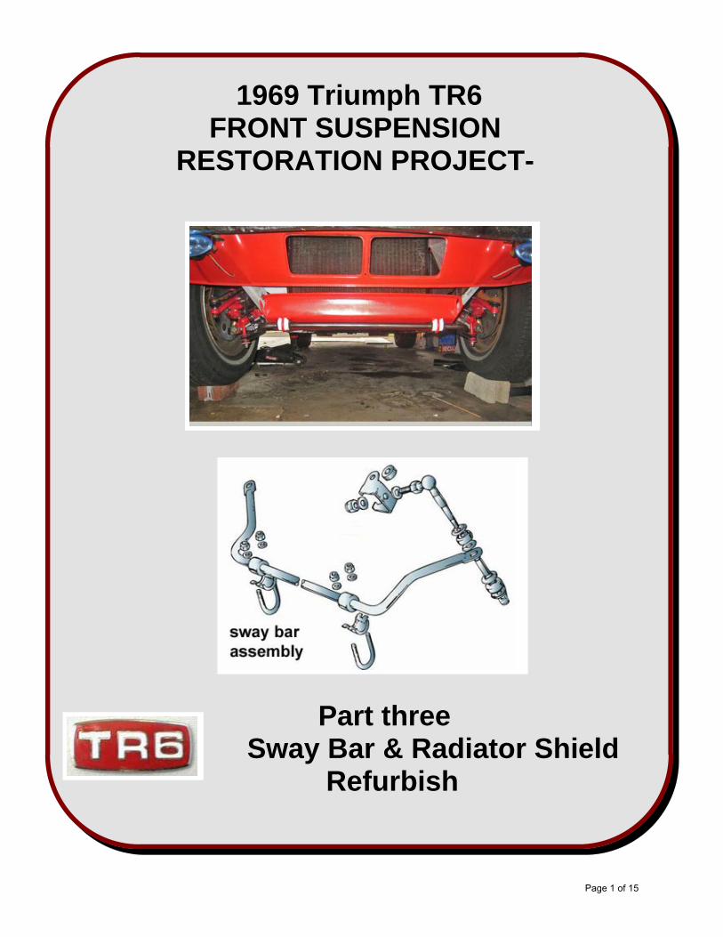
1969 Triumph TR6FRONT SUSPENSION
RESTORATION PROJECT-
Part three Sway Bar & Radiator Shield Refurbish
Page 1 of 15
SAFE HARBOUR STATEMENT:This “How I installed it” essay is presented asgeneral information and has been prepared by aTriumph TR6 owner with very limited auto mechanicknowledge. The installation procedures shown in thisdocument are not professional instructions and arenot intended to be such. The front suspension of a1969 Triumph TR6 was successfully refurbished withthese amateur procedures and I was not injuredduring the process.
The following brief essay documents the proceduresused to complete the refurbishing of the front swaybar assembly and the radiator shield component.Therefore these procedures can be used also in theroutine maintenance task of changing out the twobushings on the front of the sway bar or the verticallinks.
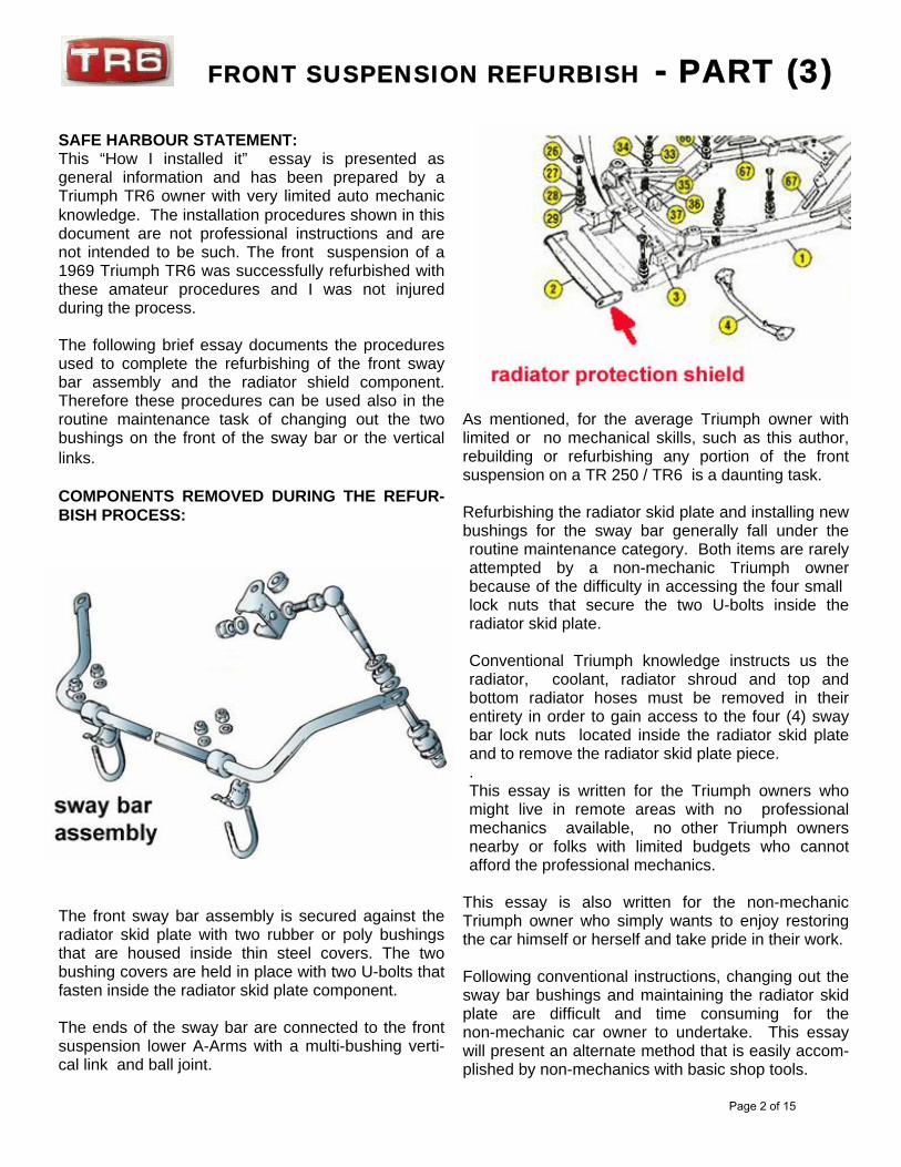
COMPONENTS REMOVED DURING THE REFUR-BISH PROCESS:
The front sway bar assembly is secured against theradiator skid plate with two rubber or poly bushingsthat are housed inside thin steel covers. The twobushing covers are held in place with two U-bolts thatfasten inside the radiator skid plate component.
The ends of the sway bar are connected to the frontsuspension lower A-Arms with a multi-bushing verti-cal link and ball joint.
As mentioned, for the average Triumph owner withlimited or no mechanical skills, such as this author,rebuilding or refurbishing any portion of the frontsuspension on a TR 250 / TR6 is a daunting task.
Refurbishing the radiator skid plate and installing newbushings for the sway bar generally fall under theroutine maintenance category. Both items are rarelyattempted by a non-mechanic Triumph ownerbecause of the difficulty in accessing the four small lock nuts that secure the two U-bolts inside theradiator skid plate.
Conventional Triumph knowledge instructs us theradiator, coolant, radiator shroud and top andbottom radiator hoses must be removed in theirentirety in order to gain access to the four (4) swaybar lock nuts located inside the radiator skid plateand to remove the radiator skid plate piece.. This essay is written for the Triumph owners whomight live in remote areas with no professionalmechanics available, no other Triumph ownersnearby or folks with limited budgets who cannotafford the professional mechanics.
This essay is also written for the non-mechanicTriumph owner who simply wants to enjoy restoringthe car himself or herself and take pride in their work.
Following conventional instructions, changing out thesway bar bushings and maintaining the radiator skidplate are difficult and time consuming for thenon-mechanic car owner to undertake. This essaywill present an alternate method that is easily accom-plished by non-mechanics with basic shop tools.
FRONT SUSPENSION REFURBISH - PART (3)
Page 2 of 15
Safety First:
SWAY BAR / SKID PLATE REMOVAL:
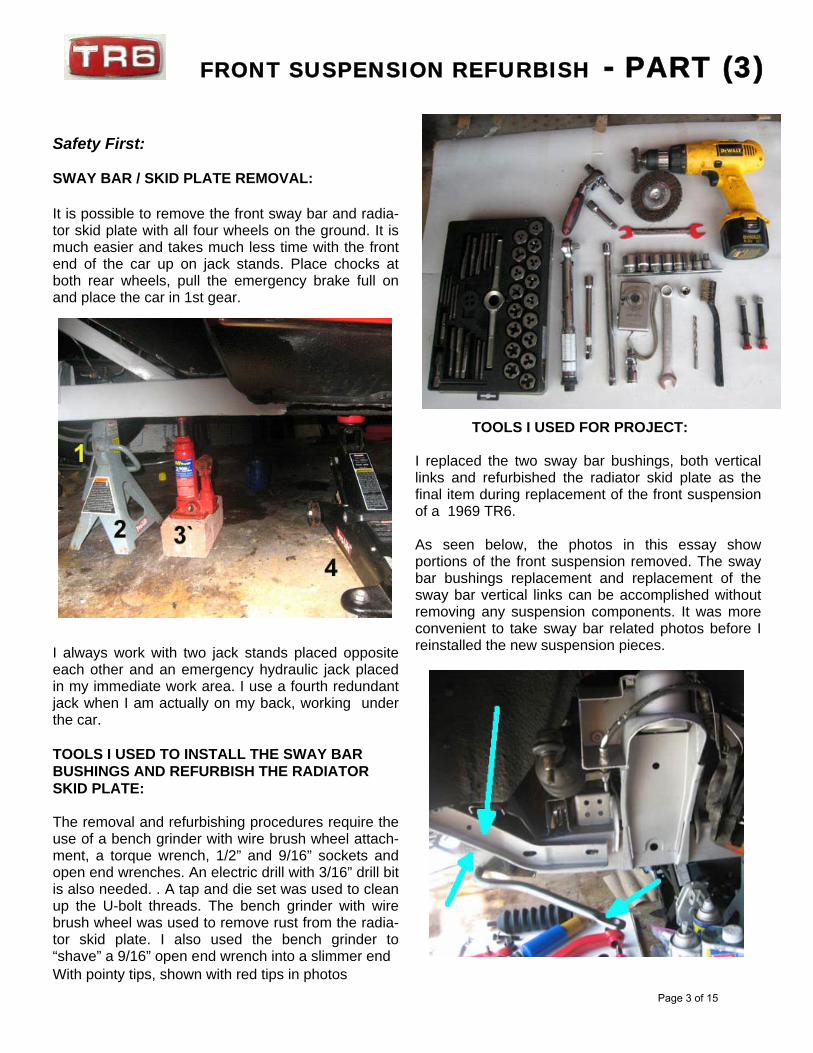
It is possible to remove the front sway bar and radia-tor skid plate with all four wheels on the ground. It ismuch easier and takes much less time with the frontend of the car up on jack stands. Place chocks atboth rear wheels, pull the emergency brake full onand place the car in 1st gear.
I always work with two jack stands placed oppositeeach other and an emergency hydraulic jack placedin my immediate work area. I use a fourth redundantjack when I am actually on my back, working underthe car.
TOOLS I USED TO INSTALL THE SWAY BARBUSHINGS AND REFURBISH THE RADIATORSKID PLATE:
The removal and refurbishing procedures require theuse of a bench grinder with wire brush wheel attach-ment, a torque wrench, 1/2” and 9/16” sockets andopen end wrenches. An electric drill with 3/16” drill bitis also needed. . A tap and die set was used to cleanup the U-bolt threads. The bench grinder with wirebrush wheel was used to remove rust from the radia-tor skid plate. I also used the bench grinder to“shave” a 9/16” open end wrench into a slimmer endWith pointy tips, shown with red tips in photos
TOOLS I USED FOR PROJECT:
I replaced the two sway bar bushings, both verticallinks and refurbished the radiator skid plate as thefinal item during replacement of the front suspensionof a 1969 TR6.
As seen below, the photos in this essay showportions of the front suspension removed. The swaybar bushings replacement and replacement of thesway bar vertical links can be accomplished withoutremoving any suspension components. It was moreconvenient to take sway bar related photos before Ireinstalled the new suspension pieces.
FRONT SUSPENSION REFURBISH - PART (3)
Page 3 of 15
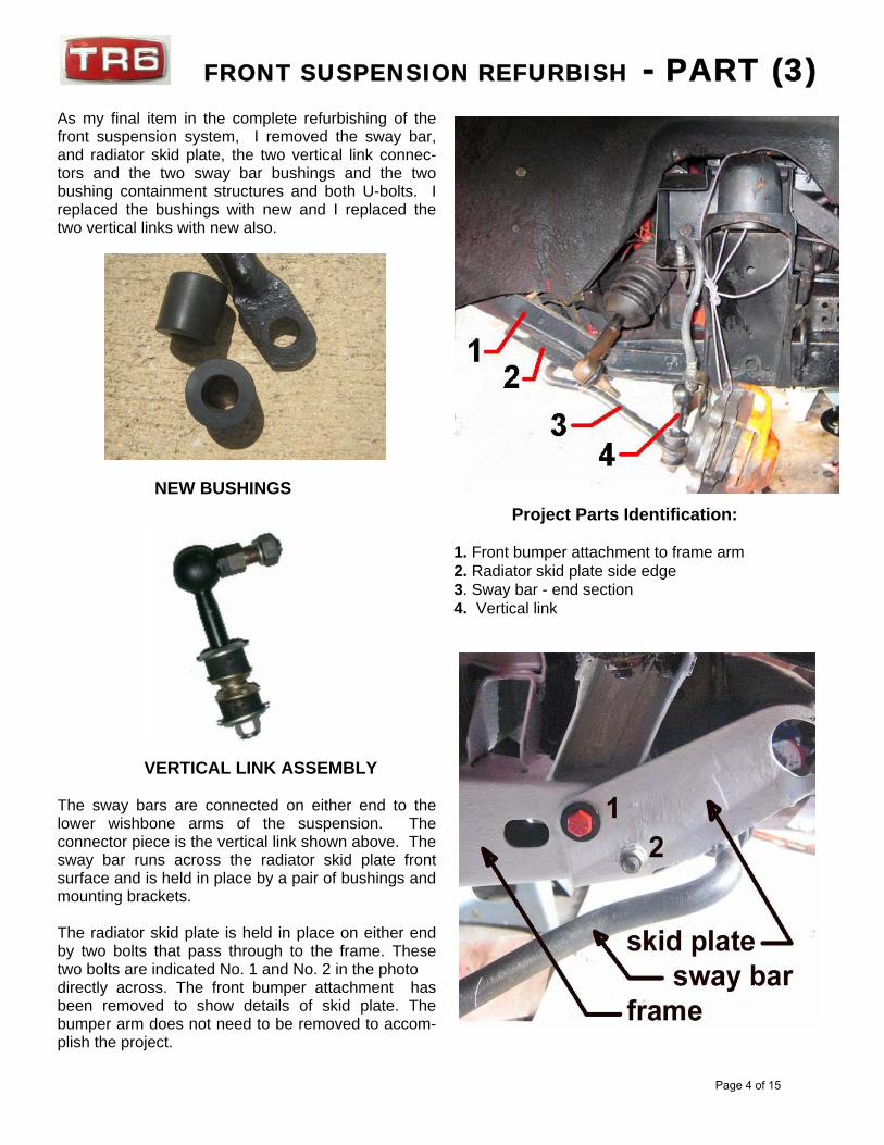
As my final item in the complete refurbishing of thefront suspension system, I removed the sway bar,and radiator skid plate, the two vertical link connec-tors and the two sway bar bushings and the twobushing containment structures and both U-bolts. Ireplaced the bushings with new and I replaced thetwo vertical links with new also.
NEW BUSHINGS
VERTICAL LINK ASSEMBLY
The sway bars are connected on either end to thelower wishbone arms of the suspension. Theconnector piece is the vertical link shown above. Thesway bar runs across the radiator skid plate frontsurface and is held in place by a pair of bushings andmounting brackets.
The radiator skid plate is held in place on either endby two bolts that pass through to the frame. Thesetwo bolts are indicated No. 1 and No. 2 in the photodirectly across. The front bumper attachment hasbeen removed to show details of skid plate. Thebumper arm does not need to be removed to accom-plish the project.
Project Parts Identification:
1. Front bumper attachment to frame arm2. Radiator skid plate side edge3. Sway bar - end section4. Vertical link
FRONT SUSPENSION REFURBISH - PART (3)
Page 4 of 15
OK, the car is safely on jack stands, the project partsare identified, new replacement parts are on handand both front wheels have been removed and setaside. It’s time to begin taking things apart.
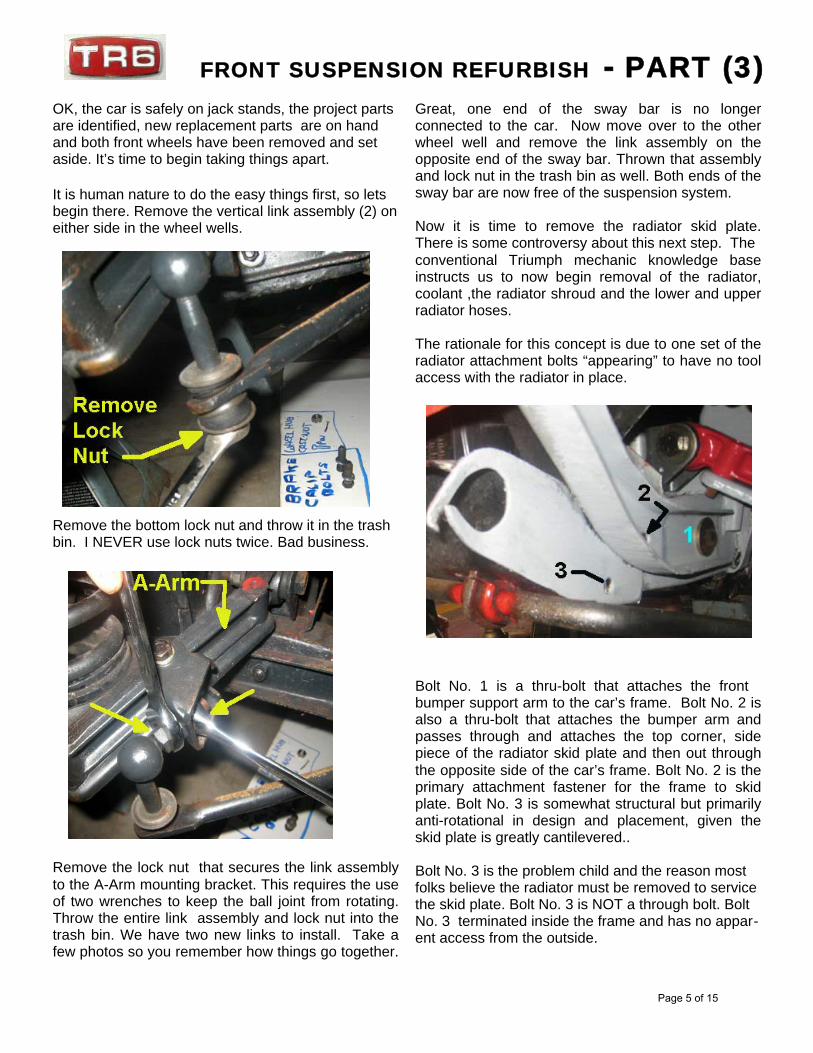
It is human nature to do the easy things first, so letsbegin there. Remove the vertical link assembly (2) oneither side in the wheel wells.
Remove the bottom lock nut and throw it in the trashbin. I NEVER use lock nuts twice. Bad business.
Remove the lock nut that secures the link assemblyto the A-Arm mounting bracket. This requires the useof two wrenches to keep the ball joint from rotating.Throw the entire link assembly and lock nut into thetrash bin. We have two new links to install. Take afew photos so you remember how things go together.
Great, one end of the sway bar is no longerconnected to the car. Now move over to the otherwheel well and remove the link assembly on theopposite end of the sway bar. Thrown that assemblyand lock nut in the trash bin as well. Both ends of thesway bar are now free of the suspension system.
Now it is time to remove the radiator skid plate.There is some controversy about this next step. Theconventional Triumph mechanic knowledge baseinstructs us to now begin removal of the radiator,coolant ,the radiator shroud and the lower and upperradiator hoses.
The rationale for this concept is due to one set of theradiator attachment bolts “appearing” to have no toolaccess with the radiator in place.
Bolt No. 1 is a thru-bolt that attaches the front bumper support arm to the car’s frame. Bolt No. 2 isalso a thru-bolt that attaches the bumper arm andpasses through and attaches the top corner, sidepiece of the radiator skid plate and then out throughthe opposite side of the car’s frame. Bolt No. 2 is theprimary attachment fastener for the frame to skidplate. Bolt No. 3 is somewhat structural but primarilyanti-rotational in design and placement, given theskid plate is greatly cantilevered..
Bolt No. 3 is the problem child and the reason mostfolks believe the radiator must be removed to servicethe skid plate. Bolt No. 3 is NOT a through bolt. BoltNo. 3 terminated inside the frame and has no appar-ent access from the outside.
FRONT SUSPENSION REFURBISH - PART (3)
Page 5 of 15
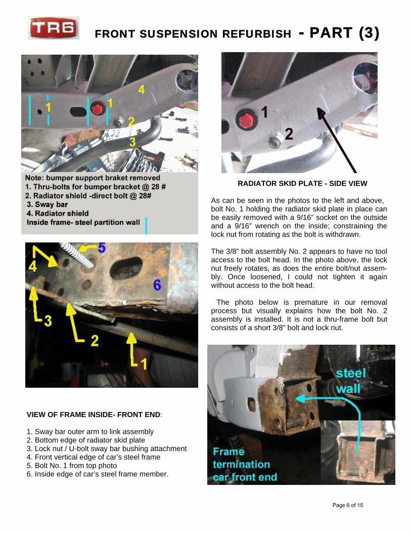
VIEW OF FRAME INSIDE- FRONT END:
1. Sway bar outer arm to link assembly2. Bottom edge of radiator skid plate3. Lock nut / U-bolt sway bar bushing attachment4. Front vertical edge of car’s steel frame5. Bolt No. 1 from top photo6. Inside edge of car’s steel frame member.
RADIATOR SKID PLATE - SIDE VIEW
As can be seen in the photos to the left and above, bolt No. 1 holding the radiator skid plate in place canbe easily removed with a 9/16” socket on the outsideand a 9/16” wrench on the inside; constraining thelock nut from rotating as the bolt is withdrawn.
The 3/8” bolt assembly No. 2 appears to have no toolaccess to the bolt head. In the photo above, the locknut freely rotates, as does the entire bolt/nut assem-bly. Once loosened, I could not tighten it againwithout access to the bolt head.
The photo below is premature in our removalprocess but visually explains how the bolt No. 2assembly is installed. It is not a thru-frame bolt butconsists of a short 3/8” bolt and lock nut.
FRONT SUSPENSION REFURBISH - PART (3)
Page 6 of 15
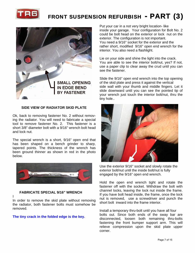
SIDE VIEW OF RADIATOR SKID PLATE
Ok, back to removing fastener No. 2 without remov-ing the radiator. You will need to fabricate a specialtool to remove fastener No. 2. This fastener is ashort 3/8” diameter bolt with a 9/16” wrench bolt headand lock nut.
The special wrench is a short, 9/16” open end thathas been shaped on a bench grinder to sharp,tapered points. The thickness of the wrench hasbeen ground thinner as shown in red in the photobelow.
FABRICATE SPECIAL 9/16” WRENCHIIn order to remove the skid plate without removingthe radiator, both fastener bolts must somehow beremoved.
The tiny crack in the folded edge is the key.
Put your car in a not very bright location- likeinside your garage. Your configuration for Bolt No. 2could be bolt head on the exterior or lock nut on theexterior. The configuration is not important.You need a 9/16" socket for the exterior and therather short, modified 9/16" open end wrench for theinterior. You also need a flashlight.
Lie on your side and shine the light into the crack.You are able to see the interior bolt/nut, yes? If not,use a paper clip to clear away the crud until you cansee the fastener.
Slide the 9/16” open end wrench into the top openingof the skid plate and press it against the verticalside wall with your thumb and middle fingers. Let itslide downward until you can see the pointed tip ofyour wrench just touch the interior bolt/nut, thru thetiny hole..
Use the exterior 9/16" socket and slowly rotate theexterior bolt/nut until the inside bolt/nut is fullyengaged by the 9/16" open end wrench.
Hold the open end wrench tight and rotate thefastener off with the socket. Withdraw the bolt withchannel locks, leaving the lock nut inside the frame.If you have bolt head inside, the frame, once the locknut is removed, use a screwdriver and punch theshort bolt inward into the frame interior.
Install a temporary thru-bolt until you have all fourbolts out. Since both ends of the sway bar aredisconnected, loosen both remaining thru-boltsfastening the front bumper support arm. This willrelieve compression upon the skid plate uppercorner.
FRONT SUSPENSION REFURBISH - PART (3)
Page 7 of 15
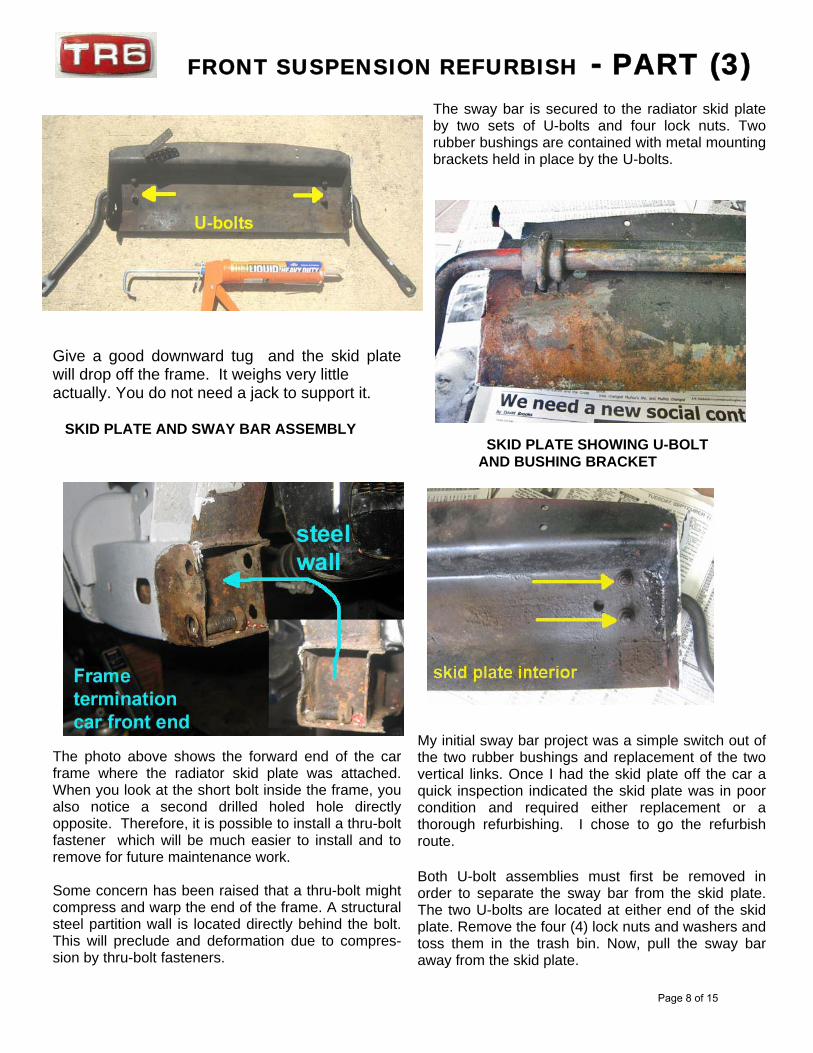
Give a good downward tug and the skid platewill drop off the frame. It weighs very littleactually. You do not need a jack to support it.
SKID PLATE AND SWAY BAR ASSEMBLY
The photo above shows the forward end of the carframe where the radiator skid plate was attached.When you look at the short bolt inside the frame, youalso notice a second drilled holed hole directlyopposite. Therefore, it is possible to install a thru-boltfastener which will be much easier to install and toremove for future maintenance work.
Some concern has been raised that a thru-bolt mightcompress and warp the end of the frame. A structuralsteel partition wall is located directly behind the bolt.This will preclude and deformation due to compres-sion by thru-bolt fasteners.
The sway bar is secured to the radiator skid plateby two sets of U-bolts and four lock nuts. Tworubber bushings are contained with metal mountingbrackets held in place by the U-bolts.
SKID PLATE SHOWING U-BOLT AND BUSHING BRACKET
My initial sway bar project was a simple switch out ofthe two rubber bushings and replacement of the twovertical links. Once I had the skid plate off the car aquick inspection indicated the skid plate was in poorcondition and required either replacement or athorough refurbishing. I chose to go the refurbishroute.
Both U-bolt assemblies must first be removed inorder to separate the sway bar from the skid plate.The two U-bolts are located at either end of the skidplate. Remove the four (4) lock nuts and washers andtoss them in the trash bin. Now, pull the sway baraway from the skid plate.
FRONT SUSPENSION REFURBISH - PART (3)
Page 8 of 15
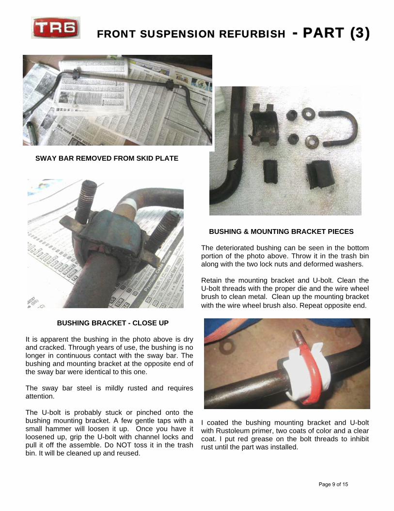
SWAY BAR REMOVED FROM SKID PLATE
BUSHING BRACKET - CLOSE UP
It is apparent the bushing in the photo above is dryand cracked. Through years of use, the bushing is nolonger in continuous contact with the sway bar. Thebushing and mounting bracket at the opposite end ofthe sway bar were identical to this one.
The sway bar steel is mildly rusted and requiresattention.
The U-bolt is probably stuck or pinched onto thebushing mounting bracket. A few gentle taps with asmall hammer will loosen it up. Once you have itloosened up, grip the U-bolt with channel locks andpull it off the assemble. Do NOT toss it in the trashbin. It will be cleaned up and reused.
BUSHING & MOUNTING BRACKET PIECES
The deteriorated bushing can be seen in the bottomportion of the photo above. Throw it in the trash binalong with the two lock nuts and deformed washers.
Retain the mounting bracket and U-bolt. Clean theU-bolt threads with the proper die and the wire wheelbrush to clean metal. Clean up the mounting bracketwith the wire wheel brush also. Repeat opposite end.
I coated the bushing mounting bracket and U-boltwith Rustoleum primer, two coats of color and a clearcoat. I put red grease on the bolt threads to inhibitrust until the part was installed.
FRONT SUSPENSION REFURBISH - PART (3)
Page 9 of 15
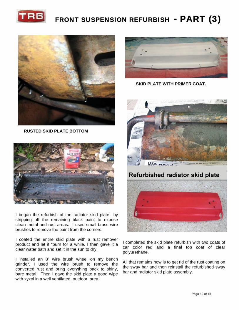
RUSTED SKID PLATE BOTTOM
I began the refurbish of the radiator skid plate bystripping off the remaining black paint to exposeclean metal and rust areas. I used small brass wirebrushes to remove the paint from the corners.
I coated the entire skid plate with a rust removerproduct and let it “burn for a while. I then gave it aclear water bath and set it in the sun to dry.
I installed an 8” wire brush wheel on my benchgrinder. I used the wire brush to remove theconverted rust and bring everything back to shiny,bare metal. Then I gave the skid plate a good wipewith xyxol in a well ventilated, outdoor area.
SKID PLATE WITH PRIMER COAT.
I completed the skid plate refurbish with two coats ofcar color red and a final top coat of clearpolyurethane.
All that remains now is to get rid of the rust coating onthe sway bar and then reinstall the refurbished swaybar and radiator skid plate assembly.
FRONT SUSPENSION REFURBISH - PART (3)
Page 10 of 15
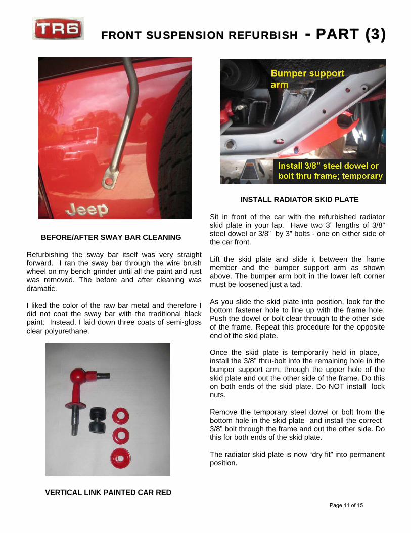
BEFORE/AFTER SWAY BAR CLEANING
Refurbishing the sway bar itself was very straightforward. I ran the sway bar through the wire brushwheel on my bench grinder until all the paint and rustwas removed. The before and after cleaning wasdramatic.
I liked the color of the raw bar metal and therefore Idid not coat the sway bar with the traditional blackpaint. Instead, I laid down three coats of semi-glossclear polyurethane.
VERTICAL LINK PAINTED CAR RED
INSTALL RADIATOR SKID PLATE
Sit in front of the car with the refurbished radiatorskid plate in your lap. Have two 3” lengths of 3/8”steel dowel or 3/8” by 3” bolts - one on either side ofthe car front.
Lift the skid plate and slide it between the framemember and the bumper support arm as shownabove. The bumper arm bolt in the lower left cornermust be loosened just a tad.
As you slide the skid plate into position, look for thebottom fastener hole to line up with the frame hole.Push the dowel or bolt clear through to the other sideof the frame. Repeat this procedure for the oppositeend of the skid plate.
Once the skid plate is temporarily held in place, install the 3/8” thru-bolt into the remaining hole in thebumper support arm, through the upper hole of theskid plate and out the other side of the frame. Do thison both ends of the skid plate. Do NOT install locknuts.
Remove the temporary steel dowel or bolt from thebottom hole in the skid plate and install the correct 3/8” bolt through the frame and out the other side. Dothis for both ends of the skid plate.
The radiator skid plate is now “dry fit” into permanentposition.
FRONT SUSPENSION REFURBISH - PART (3)
Page 11 of 15
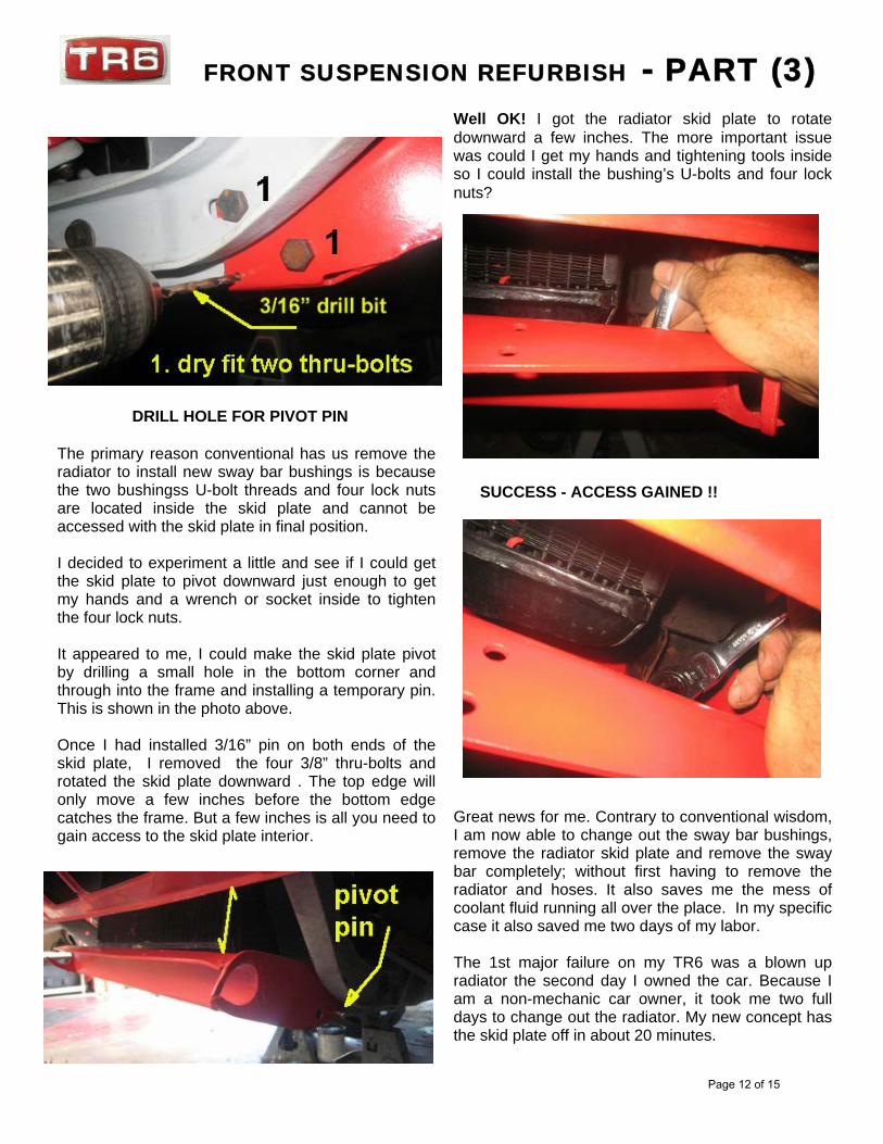
DRILL HOLE FOR PIVOT PIN
The primary reason conventional has us remove theradiator to install new sway bar bushings is becausethe two bushingss U-bolt threads and four lock nutsare located inside the skid plate and cannot beaccessed with the skid plate in final position.
I decided to experiment a little and see if I could getthe skid plate to pivot downward just enough to getmy hands and a wrench or socket inside to tightenthe four lock nuts.
It appeared to me, I could make the skid plate pivotby drilling a small hole in the bottom corner andthrough into the frame and installing a temporary pin.This is shown in the photo above.
Once I had installed 3/16” pin on both ends of theskid plate, I removed the four 3/8” thru-bolts androtated the skid plate downward . The top edge willonly move a few inches before the bottom edgecatches the frame. But a few inches is all you need togain access to the skid plate interior.
Well OK! I got the radiator skid plate to rotatedownward a few inches. The more important issuewas could I get my hands and tightening tools insideso I could install the bushing’s U-bolts and four locknuts?
SUCCESS - ACCESS GAINED !!
Great news for me. Contrary to conventional wisdom,I am now able to change out the sway bar bushings,remove the radiator skid plate and remove the swaybar completely; without first having to remove theradiator and hoses. It also saves me the mess ofcoolant fluid running all over the place. In my specificcase it also saved me two days of my labor.
The 1st major failure on my TR6 was a blown upradiator the second day I owned the car. Because Iam a non-mechanic car owner, it took me two fulldays to change out the radiator. My new concept hasthe skid plate off in about 20 minutes.
FRONT SUSPENSION REFURBISH - PART (3)
Page 12 of 15
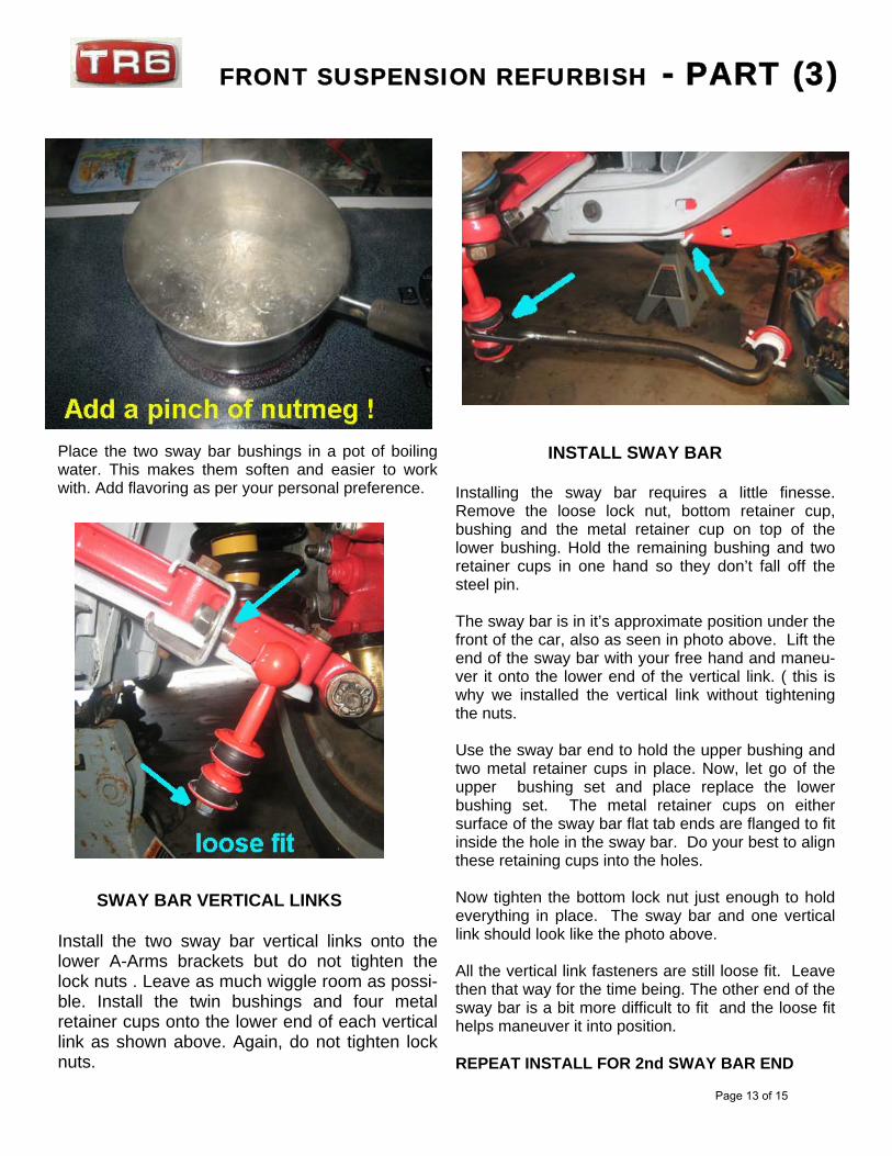
Place the two sway bar bushings in a pot of boilingwater. This makes them soften and easier to workwith. Add flavoring as per your personal preference.
SWAY BAR VERTICAL LINKS
Install the two sway bar vertical links onto thelower A-Arms brackets but do not tighten thelock nuts . Leave as much wiggle room as possi-ble. Install the twin bushings and four metalretainer cups onto the lower end of each verticallink as shown above. Again, do not tighten locknuts.
INSTALL SWAY BAR
Installing the sway bar requires a little finesse.Remove the loose lock nut, bottom retainer cup,bushing and the metal retainer cup on top of thelower bushing. Hold the remaining bushing and tworetainer cups in one hand so they don’t fall off thesteel pin.
The sway bar is in it’s approximate position under thefront of the car, also as seen in photo above. Lift theend of the sway bar with your free hand and maneu-ver it onto the lower end of the vertical link. ( this iswhy we installed the vertical link without tighteningthe nuts.
Use the sway bar end to hold the upper bushing andtwo metal retainer cups in place. Now, let go of theupper bushing set and place replace the lowerbushing set. The metal retainer cups on eithersurface of the sway bar flat tab ends are flanged to fitinside the hole in the sway bar. Do your best to alignthese retaining cups into the holes.
Now tighten the bottom lock nut just enough to holdeverything in place. The sway bar and one verticallink should look like the photo above.
All the vertical link fasteners are still loose fit. Leavethen that way for the time being. The other end of thesway bar is a bit more difficult to fit and the loose fithelps maneuver it into position.
REPEAT INSTALL FOR 2nd SWAY BAR END
FRONT SUSPENSION REFURBISH - PART (3)
Page 13 of 15
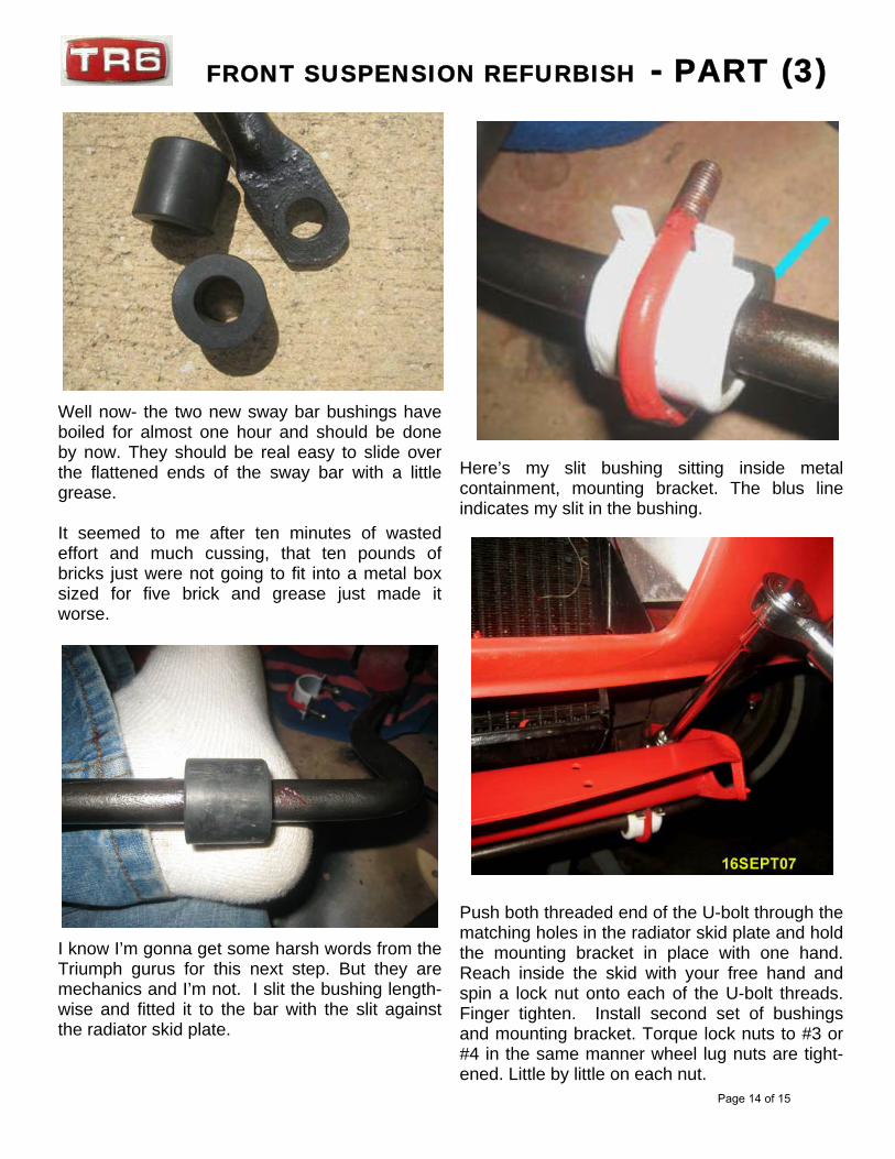
Well now- the two new sway bar bushings haveboiled for almost one hour and should be doneby now. They should be real easy to slide overthe flattened ends of the sway bar with a littlegrease.
It seemed to me after ten minutes of wastedeffort and much cussing, that ten pounds ofbricks just were not going to fit into a metal boxsized for five brick and grease just made itworse.
I know I’m gonna get some harsh words from theTriumph gurus for this next step. But they aremechanics and I’m not. I slit the bushing length-wise and fitted it to the bar with the slit againstthe radiator skid plate.
Here’s my slit bushing sitting inside metalcontainment, mounting bracket. The blus lineindicates my slit in the bushing.
Push both threaded end of the U-bolt through thematching holes in the radiator skid plate and holdthe mounting bracket in place with one hand.Reach inside the skid with your free hand andspin a lock nut onto each of the U-bolt threads.Finger tighten. Install second set of bushingsand mounting bracket. Torque lock nuts to #3 or#4 in the same manner wheel lug nuts are tight-ened. Little by little on each nut.
FRONT SUSPENSION REFURBISH - PART (3)
Page 14 of 15
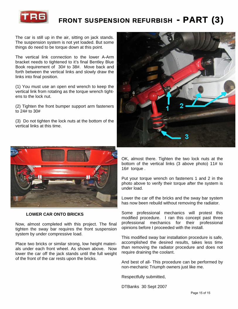
The car is still up in the air, sitting on jack stands.The suspension system is not yet loaded. But somethings do need to be torque down at this point.
The vertical link connection to the lower A-Armbracket needs to tightened to it’s final Bentley BlueBook requirement of 30# to 38#. Move back andforth between the vertical links and slowly draw thelinks into final position.
(1) You must use an open end wrench to keep thevertical link from rotating as the torque wrench tight-ens to the lock nut.
(2) Tighten the front bumper support arm fastenersto 24# to 30#
(3) Do not tighten the lock nuts at the bottom of thevertical links at this time.
LOWER CAR ONTO BRICKS
Now, almost completed with this project. The finaltighten the sway bar requires the front suspensionsystem by under compressive load.
Place two bricks or similar strong, low height materi-als under each front wheel. As shown above. Nowlower the car off the jack stands until the full weightof the front of the car rests upon the bricks.
OK, almost there. Tighten the two lock nuts at thebottom of the vertical links (3 above photo) 11# to16# torque .
Put your torque wrench on fasteners 1 and 2 in thephoto above to verify their torque after the system isunder load.
Lower the car off the bricks and the sway bar systemhas now been rebuild without removing the radiator.
Some professional mechanics will protest thismodified procedure. I ran this concept past threeprofessional mechanics for their professionalopinions before I proceeded with the install.
This modified sway bar installation procedure is safe,accomplished the desired results, takes less timethan removing the radiator procedure and does notrequire draining the coolant.
And best of all- This procedure can be performed bynon-mechanic Triumph owners just like me.
Respectfully submitted,
DTBanks 30 Sept 2007
FRONT SUSPENSION REFURBISH - PART (3)
Page 15 of 15