swg 11.7 user guide - trustwavemeaning blue underline a blue underline indicates a web site or email...
TRANSCRIPT

Secure Web GatewayVersion 11.7User Guide

Secure Web Gateway 11.7 User Guide
Legal Notice
Copyright © 2015 Trustwave Holdings, Inc.
All rights reserved. This document is protected by copyright and any distribution, reproduction, copying, or decompilation is strictly prohibited without the prior written consent of Trustwave. No part of this document may be reproduced in any form or by any means without the prior written authorization of Trustwave. While every precaution has been taken in the preparation of this document, Trustwave assumes no responsibility for errors or omissions. This publication and features described herein are subject to change without notice.
While the authors have used their best efforts in preparing this document, they make no representation or warranties with respect to the accuracy or completeness of the contents of this document and specifically disclaim any implied warranties of merchantability or fitness for a particular purpose. No warranty may be created or extended by sales representatives or written sales materials. The advice and strategies contained herein may not be suitable for your situation. You should consult with a professional where appropriate. Neither the author nor Trustwave shall be liable for any loss of profit or any commercial damages, including but not limited to direct, indirect, special, incidental, consequential, or other damages.
The most current version of this document may be obtained by contacting:
Trustwave Technical Support:Phone: +1.800.363.1621Email: [email protected]
Trademarks
Trustwave and the Trustwave logo are trademarks of Trustwave. Such trademarks shall not be used,copied, or disseminated in any manner without the prior written permission of Trustwave.
Revision History
Version Date Changes
1.0 March 2013 Version 11.0 Release
2.0 November 2013 Version 11.5 Release
3.0 November 2014 Version 11.6 Release
4.0 March 2015 Version 11.7 Release
Legal NoticeCopyright © 2015 Trustwave Holdings, Inc. All rights reserved. ii
Secure Web Gateway 11.7 User Guide
Formatting Conventions
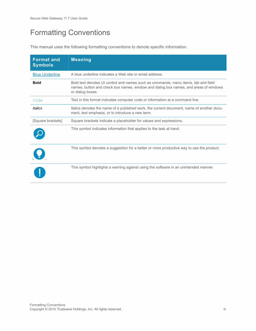
This manual uses the following formatting conventions to denote specific information.
Format and Symbols
Meaning
Blue Underline A blue underline indicates a Web site or email address.
Bold Bold text denotes UI control and names such as commands, menu items, tab and field names, button and check box names, window and dialog box names, and areas of windows or dialog boxes.
Code Text in this format indicates computer code or information at a command line.
Italics Italics denotes the name of a published work, the current document, name of another docu-ment, text emphasis, or to introduce a new term.
[Square brackets] Square brackets indicate a placeholder for values and expressions.
This symbol indicates information that applies to the task at hand.
This symbol denotes a suggestion for a better or more productive way to use the product.
This symbol highlights a warning against using the software in an unintended manner.
Formatting ConventionsCopyright © 2015 Trustwave Holdings, Inc. All rights reserved. iii

Secure Web Gateway 11.7 User Guide
About This Guide
The SWG User Guide describes the procedures that you perform on the Management Console to implement, use, and maintain Secure Web Gateway (SWG) in your organization. The Management Console is your interface to SWG.
It is important to note that this guide is not a reference guide. It does not provide a detailed description of all Management Console screens, or fields. Nor does it provide a detailed description of concepts that apply to SWG and the Management Console. For that information, see the SWG Management Console
Reference Guide.
This guide assumes that:
• you have already installed the Secure Web Gateway in your organization. For installation instructions, see the Secure Web Gateway Installation Guide.
• you have set up the SWG using the Limited Shell. For setup instructions, see the Secure Web Gateway Setup Guide.
• you have already planned out your security needs.
This guide is divided into Parts and Chapters. These parts and chapters are organized in the sequence in which you are likely to use them when first implementing SWG. You can, of course, use any procedure at any time that you need.
• PART 1: Initial Management Console Tasks - describes how to perform preliminary and basic tasks in the Management Console, and manage devices and device groups.
• PART 2: Implementing User Security Policies - describes how to define and manage security policies and users.
• PART 3: Configuring Advanced Network Settings - describes how to define and assign Identification, Proxy, and Caching policies.
• PART 4: Configuring Logging and Alert Settings - describes how to define Logging policy, configure the Log Server, and configure alerts.
• PART 5: Performing Monitoring and Maintenance - describes how to view the security status, and manage logs and reports.
• PART 6: Performing Advanced Configuration - describes additional advanced configuration tasks such as enabling HTTPS scanning, and implementing Cloud security and ICAP services.
About This GuideCopyright © 2015 Trustwave Holdings, Inc. All rights reserved. iv
Secure Web Gateway 11.7 User Guide
SWG Documentation Set
The SWG documentation set includes the following guides:
• Secure Web Gateway Installation Guide
• Secure Web Gateway Setup Guide
• Management Console Reference Guide
• Secure Web Gateway User Guide
• Secure Web Gateway User Security Policies In-Depth Guide
• Secure Web Gateway User Identification Guide
SWG Documentation SetCopyright © 2015 Trustwave Holdings, Inc. All rights reserved. v

Secure Web Gateway 11.7 User Guide
Table of ContentsLegal Notice . . . . . . . . . . . . . . . . . . . . . . . . . . . . . . . . . . . . . . . . . . . . . . . . . . . . . . . . . . . . . . . . . . . . . . . . ii
Revision History . . . . . . . . . . . . . . . . . . . . . . . . . . . . . . . . . . . . . . . . . . . . . . . . . . . . . . . . . . . . . . . . . . . . . ii
Formatting Conventions . . . . . . . . . . . . . . . . . . . . . . . . . . . . . . . . . . . . . . . . . . . . . . . . . . . . . . . . . . . . . . . iii
About This Guide . . . . . . . . . . . . . . . . . . . . . . . . . . . . . . . . . . . . . . . . . . . . . . . . . . . . . . . . . . . . . . . . . . . . iv
SWG Documentation Set . . . . . . . . . . . . . . . . . . . . . . . . . . . . . . . . . . . . . . . . . . . . . . . . . . . . . . . . . . . . . . v
PART 1: Initial Management Console Tasks . . . . . . . . . . . . . . . . . . . . . . . . . . . . . . . . . . . . . . . . . . . . . . 10
1 Getting Started 11
1.1 Performing Preliminary Tasks . . . . . . . . . . . . . . . . . . . . . . . . . . . . . . . . . . . . . . . . . . . . . . . . . . . 111.2 General Screen Usage and Navigation. . . . . . . . . . . . . . . . . . . . . . . . . . . . . . . . . . . . . . . . . . . . 131.3 Performing Basic Tasks in the Management Console . . . . . . . . . . . . . . . . . . . . . . . . . . . . . . . . 15
2 Configuring/Adding Scanning Servers 18
2.1 Configuring Device General Settings . . . . . . . . . . . . . . . . . . . . . . . . . . . . . . . . . . . . . . . . . . . . . 182.2 Adding Devices and Device Groups . . . . . . . . . . . . . . . . . . . . . . . . . . . . . . . . . . . . . . . . . . . . . . 202.3 Moving Scanning Servers to a Different Group. . . . . . . . . . . . . . . . . . . . . . . . . . . . . . . . . . . . . . 22
PART 2: Implementing User Security Policies . . . . . . . . . . . . . . . . . . . . . . . . . . . . . . . . . . . . . . . . . . . . . 23
3 Defining and Customizing Security Policies 24
3.1 Defining a Rule in a Security Policy . . . . . . . . . . . . . . . . . . . . . . . . . . . . . . . . . . . . . . . . . . . . . . 253.2 Defining Conditions in a Security Policy Rule . . . . . . . . . . . . . . . . . . . . . . . . . . . . . . . . . . . . . . . 263.3 Testing Security Policies . . . . . . . . . . . . . . . . . . . . . . . . . . . . . . . . . . . . . . . . . . . . . . . . . . . . . . . 283.4 Creating a Block/Warn Message. . . . . . . . . . . . . . . . . . . . . . . . . . . . . . . . . . . . . . . . . . . . . . . . . 293.5 Editing a Message Template. . . . . . . . . . . . . . . . . . . . . . . . . . . . . . . . . . . . . . . . . . . . . . . . . . . . 30
4 Defining and Managing Users 31
4.1 Setting Default User Policy Assignments . . . . . . . . . . . . . . . . . . . . . . . . . . . . . . . . . . . . . . . . . . 324.2 Defining and Managing LDAP Users . . . . . . . . . . . . . . . . . . . . . . . . . . . . . . . . . . . . . . . . . . . . . 324.3 Defining and Managing Trustwave (Non-LDAP) Users. . . . . . . . . . . . . . . . . . . . . . . . . . . . . . . . 374.4 Defining User Lists . . . . . . . . . . . . . . . . . . . . . . . . . . . . . . . . . . . . . . . . . . . . . . . . . . . . . . . . . . . 40
Copyright © 2015 Trustwave Holdings, Inc. All rights reserved. vi

Secure Web Gateway 11.7 User Guide
PART 3: Configuring Advanced Network Settings . . . . . . . . . . . . . . . . . . . . . . . . . . . . . . . . . . . . . . . . . . 42
5 Implementing Identification Policy 43
5.1 Defining and Customizing Identification Policy . . . . . . . . . . . . . . . . . . . . . . . . . . . . . . . . . . . . . . 435.2 Defining a Realm. . . . . . . . . . . . . . . . . . . . . . . . . . . . . . . . . . . . . . . . . . . . . . . . . . . . . . . . . . . . . 46
6 Implementing Authentication 47
6.1 Configuring Default and Scanning Server Authentication . . . . . . . . . . . . . . . . . . . . . . . . . . . . . . 47
7 Working with Kerberos 50
7.1 Terminology . . . . . . . . . . . . . . . . . . . . . . . . . . . . . . . . . . . . . . . . . . . . . . . . . . . . . . . . . . . . . . . . 507.2 Kerberos Requirements . . . . . . . . . . . . . . . . . . . . . . . . . . . . . . . . . . . . . . . . . . . . . . . . . . . . . . . 517.3 Setting up Kerberos . . . . . . . . . . . . . . . . . . . . . . . . . . . . . . . . . . . . . . . . . . . . . . . . . . . . . . . . . . 51
8 Defining and Customizing Upstream Proxy Policy 54
8.1 Defining an Upstream Proxy Policy. . . . . . . . . . . . . . . . . . . . . . . . . . . . . . . . . . . . . . . . . . . . . . . 548.2 Defining a Rule in an Upstream Proxy Policy . . . . . . . . . . . . . . . . . . . . . . . . . . . . . . . . . . . . . . . 558.3 Defining Conditions in an Upstream Proxy Rule . . . . . . . . . . . . . . . . . . . . . . . . . . . . . . . . . . . . . 56
9 Enabling and Customizing Caching 57
9.1 Enabling Caching . . . . . . . . . . . . . . . . . . . . . . . . . . . . . . . . . . . . . . . . . . . . . . . . . . . . . . . . . . . . 579.2 Defining a Caching Policy . . . . . . . . . . . . . . . . . . . . . . . . . . . . . . . . . . . . . . . . . . . . . . . . . . . . . . 589.3 Defining a Rule in a Caching Policy . . . . . . . . . . . . . . . . . . . . . . . . . . . . . . . . . . . . . . . . . . . . . . 599.4 Defining Conditions in a Caching Rule . . . . . . . . . . . . . . . . . . . . . . . . . . . . . . . . . . . . . . . . . . . . 60
10 Assigning Policies To Devices 61
10.1 Setting Device Policy Defaults . . . . . . . . . . . . . . . . . . . . . . . . . . . . . . . . . . . . . . . . . . . . . . . . . 6110.2 Assigning Policies to Specific Devices . . . . . . . . . . . . . . . . . . . . . . . . . . . . . . . . . . . . . . . . . . . 61
PART 4: Configuring Logging and Alert Settings . . . . . . . . . . . . . . . . . . . . . . . . . . . . . . . . . . . . . . . . . . . 62
11 Defining and Customizing Logging Policy 63
11.1 Defining a Logging Policy . . . . . . . . . . . . . . . . . . . . . . . . . . . . . . . . . . . . . . . . . . . . . . . . . . . . . 6311.2 Defining a Rule in a Logging Policy . . . . . . . . . . . . . . . . . . . . . . . . . . . . . . . . . . . . . . . . . . . . . 6411.3 Defining Conditions in a Logging Rule . . . . . . . . . . . . . . . . . . . . . . . . . . . . . . . . . . . . . . . . . . . 65
12 Configuring the Log Server 67
12.1 Configuring Log Server Settings . . . . . . . . . . . . . . . . . . . . . . . . . . . . . . . . . . . . . . . . . . . . . . . . 67
vii Copyright © 2015 Trustwave Holdings, Inc. All rights reserved.

Secure Web Gateway 11.7 User Guide
13 Configuring Alerts 75
13.1 Assigning Alert Channels to Event Types . . . . . . . . . . . . . . . . . . . . . . . . . . . . . . . . . . . . . . . . . 7513.2 Configuring SNMP Settings . . . . . . . . . . . . . . . . . . . . . . . . . . . . . . . . . . . . . . . . . . . . . . . . . . . 7613.3 Setting Thresholds for Security Alert Notifications . . . . . . . . . . . . . . . . . . . . . . . . . . . . . . . . . . 78
PART 5: Performing Monitoring and Maintenance . . . . . . . . . . . . . . . . . . . . . . . . . . . . . . . . . . . . . . . . . . 79
14 Viewing Security and Component Statuses 80
14.1 Viewing Security Status Information (Dashboard) . . . . . . . . . . . . . . . . . . . . . . . . . . . . . . . . . . 8014.2 Viewing Dynamic Component Information . . . . . . . . . . . . . . . . . . . . . . . . . . . . . . . . . . . . . . . . 81
15 Viewing Logs 82
15.1 Viewing Logs. . . . . . . . . . . . . . . . . . . . . . . . . . . . . . . . . . . . . . . . . . . . . . . . . . . . . . . . . . . . . . . 8215.2 Creating, Editing, and Managing Log Views . . . . . . . . . . . . . . . . . . . . . . . . . . . . . . . . . . . . . . . 8415.3 Viewing Transaction Details (Web Log only) . . . . . . . . . . . . . . . . . . . . . . . . . . . . . . . . . . . . . . 86
16 Viewing and Working With Reports 87
16.1 Running and Viewing Reports. . . . . . . . . . . . . . . . . . . . . . . . . . . . . . . . . . . . . . . . . . . . . . . . . . 8716.2 Creating or Modifying Report Definitions . . . . . . . . . . . . . . . . . . . . . . . . . . . . . . . . . . . . . . . . . 8816.3 Managing Reports. . . . . . . . . . . . . . . . . . . . . . . . . . . . . . . . . . . . . . . . . . . . . . . . . . . . . . . . . . . 89
17 Maintaining Your System 94
17.1 Performing Manual Backup and Restore . . . . . . . . . . . . . . . . . . . . . . . . . . . . . . . . . . . . . . . . . 9417.2 Viewing and Installing Updates . . . . . . . . . . . . . . . . . . . . . . . . . . . . . . . . . . . . . . . . . . . . . . . . . 9517.3 Importing From and Exporting Policy Databases . . . . . . . . . . . . . . . . . . . . . . . . . . . . . . . . . . . 96
PART 6: Performing Advanced Configuration . . . . . . . . . . . . . . . . . . . . . . . . . . . . . . . . . . . . . . . . . . . . . 99
18 Defining Administrators 100
18.1 Creating/Editing an Administrator Group . . . . . . . . . . . . . . . . . . . . . . . . . . . . . . . . . . . . . . . . 10018.2 Creating/Editing an Administrator . . . . . . . . . . . . . . . . . . . . . . . . . . . . . . . . . . . . . . . . . . . . . . 10118.3 Setting Access Permissions . . . . . . . . . . . . . . . . . . . . . . . . . . . . . . . . . . . . . . . . . . . . . . . . . . 10218.4 Configuring RADIUS Server Authentication . . . . . . . . . . . . . . . . . . . . . . . . . . . . . . . . . . . . . . 104
19 Performing Additional Configuration Tasks 105
19.1 Adjusting Network Settings for a Device . . . . . . . . . . . . . . . . . . . . . . . . . . . . . . . . . . . . . . . . . 10519.2 Configuring a Device to Use an NTP Server. . . . . . . . . . . . . . . . . . . . . . . . . . . . . . . . . . . . . . 10719.3 Enabling Dynamic URL Categorization. . . . . . . . . . . . . . . . . . . . . . . . . . . . . . . . . . . . . . . . . . 10719.4 Configuring Administrative Settings . . . . . . . . . . . . . . . . . . . . . . . . . . . . . . . . . . . . . . . . . . . . 10819.5 Importing Digital Certificates . . . . . . . . . . . . . . . . . . . . . . . . . . . . . . . . . . . . . . . . . . . . . . . . . . 109
Copyright © 2015 Trustwave Holdings, Inc. All rights reserved. viii

Secure Web Gateway 11.7 User Guide
19.6 Configuring Backup Settings. . . . . . . . . . . . . . . . . . . . . . . . . . . . . . . . . . . . . . . . . . . . . . . . . . 10919.7 Configuring Automatic Update Handling . . . . . . . . . . . . . . . . . . . . . . . . . . . . . . . . . . . . . . . . . 11119.8 Defining and Customizing Device Logging Policy. . . . . . . . . . . . . . . . . . . . . . . . . . . . . . . . . . 11219.9 Configuring Default and Device-Specific Access Lists . . . . . . . . . . . . . . . . . . . . . . . . . . . . . . 11419.10 Configuring Transparent Proxy Mode . . . . . . . . . . . . . . . . . . . . . . . . . . . . . . . . . . . . . . . . . . 11619.11 Scheduling Configuration and Security Updates for Scanning Server Device Groups . . . . . 11719.12 Implementing High Availability . . . . . . . . . . . . . . . . . . . . . . . . . . . . . . . . . . . . . . . . . . . . . . . 11819.13 Implementing Disaster Recovery . . . . . . . . . . . . . . . . . . . . . . . . . . . . . . . . . . . . . . . . . . . . . 11919.14 Modifying LDAP Directory Advanced Settings . . . . . . . . . . . . . . . . . . . . . . . . . . . . . . . . . . . 120
20 Enabling HTTPS Scanning 122
20.1 Defining an HTTPS Policy. . . . . . . . . . . . . . . . . . . . . . . . . . . . . . . . . . . . . . . . . . . . . . . . . . . . 12220.2 Configuring and Certifying HTTPS . . . . . . . . . . . . . . . . . . . . . . . . . . . . . . . . . . . . . . . . . . . . . 125
21 Implementing Cloud Security 128
21.1 Implementing Cloud Security Outline . . . . . . . . . . . . . . . . . . . . . . . . . . . . . . . . . . . . . . . . . . . 12921.2 Setting the Certificate Management Mode . . . . . . . . . . . . . . . . . . . . . . . . . . . . . . . . . . . . . . . 13021.3 Configuring Cloud Settings in Identification Only Mode . . . . . . . . . . . . . . . . . . . . . . . . . . . . . 13021.4 Configuring Cloud Settings in Internal Certification Mode. . . . . . . . . . . . . . . . . . . . . . . . . . . . 13421.5 Configuring Cloud Settings in PKI Mode. . . . . . . . . . . . . . . . . . . . . . . . . . . . . . . . . . . . . . . . . 13821.6 Certifying and Managing Cloud Users . . . . . . . . . . . . . . . . . . . . . . . . . . . . . . . . . . . . . . . . . . 14121.7 Defining a Private Cloud Scanner . . . . . . . . . . . . . . . . . . . . . . . . . . . . . . . . . . . . . . . . . . . . . . 144
22 Implementing ICAP 146
22.1 Configuring SWG to Provide ICAP Services. . . . . . . . . . . . . . . . . . . . . . . . . . . . . . . . . . . . . . 14622.2 Configuring SWG to Use External ICAP Services . . . . . . . . . . . . . . . . . . . . . . . . . . . . . . . . . 147
ix Copyright © 2015 Trustwave Holdings, Inc. All rights reserved.
Secure Web Gateway 11.7 User Guide
PART 1: Initial Management Console TasksCopyright © 2015 Trustwave Holdings, Inc. All rights reserved. 10
PART 1: Initial Management Console Tasks
This part contains the following chapters:
• Chapter 1: Getting Started
• Chapter 2: Configuring/Adding Scanning Servers

Secure Web Gateway 11.7 User Guide
1 Getting Started
The Secure Web Gateway (SWG) Management Console provides administrators with a tool for managing the entire SWG deployment using a Web browser.
This section contains the following topics:
• Performing Preliminary Tasks
• General Screen Usage and Navigation
• Performing Basic Tasks in the Management Console
1.1 Performing Preliminary TasksBefore performing any preliminary tasks, ensure that:
• SWG is installed. For installation instructions, see the Secure Web Gateway Installation Guide.
• SWG is set up using the Limited Shell. For setup instructions, see the Secure Web Gateway Setup
Guide.
• The License key for SWG is available.
• The Policy Server IP is added to the Proxy Server Exceptions in the Internet settings to ensure optimum performance (optional).
• The organization’s security requirements are defined and prepared for implementation.
This section contains the following topics:
• Performing First Time Login, Password Change, and License Installation
• Configuring the Mail Server
1.1.1 Performing First Time Login, Password Change, and License InstallationWhen logging into the Management Console for the first time:
1. In your Web browser, enter https://<appliance IP address>.
If an alert message identifies a problem with the Website (for example, its security certificate), continueto the Website, even if the message warns that this is not recommended.
The Login window is displayed.
2. Enter the administrator user name (default: admin) and password (default: TrustwaveSWG).
The Change Password window is displayed.
The password must be changed when logging in to SWG for the first time.
Getting Started11 Copyright © 2015 Trustwave Holdings, Inc. All rights reserved.

Secure Web Gateway 11.7 User Guide
3. Enter the following:
• Old Password — The current administrator password
• New Password — A new password
• Confirm Password — Reenter the new password
4. Click Change Password.
The License window is displayed.
5. In the License window, enter the License key and click Continue.
The Trustwave SWG Welcome Screen is displayed.
1.1.1.1 Welcome ScreenThe Welcome screen opens only at the first login after installation, or if the user does not have permissions to access the Home page.
This screen provides quick links to several frequently-used activities. Note that you can also display these links in the Home page, if required. For more information, see Customizing the Home Page.
1.1.2 Configuring the Mail ServerThe Mail Server controls the sending of emails for system events, application events, and software updates. The server uses Simple Mail Transfer Protocol (SMTP).
You define the settings for the Mail Server in the Mail Server Setting Screen.
To configure the Mail Server:
1. Select Administration | System Settings | Mail Server and click the Edit button.
2. To enable the sending of email, ensure that the Enable Sending Email check box is selected.
3. In the Hostname/IP field, specify the IP address, or hostname, of the SMTP Server you are using (for example, mail.Trustwave.com).
4. In the Port field, specify the number of the port that the SMTP Server uses, usually 25 is specified.
5. In the User Name and Password fields, specify the User name and Password used for SMTP Authentication. This is optional, depending on your SMTP requirements.
6. In the Originating Domain field, specify the domain from which emails will be sent.
7. In the Test Recipient field, specify the email address to which the test email will be sent, to validate that the messages are being received (for example, [email protected]).
8. Click Test. A sample email alert will be sent to the Test Recipient email address.
9. Click Save.
10. If you are ready to distribute and implement the changes in your system devices, click Commit .
Getting StartedCopyright © 2015 Trustwave Holdings, Inc. All rights reserved. 12

Secure Web Gateway 11.7 User Guide
1.2 General Screen Usage and NavigationMost windows are used for defining and configuring. Some windows provide only information, and cannot be updated. A grayed-out field or button (for example, the Edit button) means that the user is not allowed to perform the relevant update. Some windows provide lists of information that are editable.
1.2.1 Main WindowThe Main Window is where you define or view the details of a feature. Note the following:
• Right Pane and Left Pane: Most sections of the SWG GUI display a Right Pane containing detailed information about the item selected in the Left Pane. Many definition/configuration windows in the right pane contain tabs, with each tab containing relevant fields or information.
• Data refresh: Clicking the Refresh button at the top right of the pane manually refreshes the GUI to display current information.
• Quick-access icons: Many tree panes have action icons to the left of the tree entries. You can select an entry in the tree, and then click the appropriate action icon. Pop-up tooltips provide a description of each icon. You can also right-click a tree item to open a context-sensitive menu.
• Tabs: Using tabs can save time when switching back and forth between commonly used areas of the GUI.
• Clicking the tab opens another window instance. By default, the Home page is displayed. You can navigate to another location in the new window.
• You can define the tabs that open when SWG is launched after a refresh or logout. Go to Administration | System Settings | Administrative Settings and edit the Startup Tabs tab.
• Item Detail: Some list screens have an icon that displays the details of the item when clicked.
• Editing: Most windows used for editing provide Edit, Save, and Cancel buttons. To edit an existing definition, you must click the Edit button first; until you do, the definition fields are displayed in protected mode and cannot be modified.
• Mandatory fields appear in yellow when empty (or in some cases, if they contain invalid data). In
multi-tab screens, if mandatory data is missing, the symbol appears at the top of the tab.
• Commit Changes: After defining or configuring a component and performing a Save, you must click
Commit Changes in the toolbar to synchronize the Policy Server and the scanners. The Commit Changes window that opens contains two tabs:
• General: Enables you to add a note describing the change. The note will appear in the Audit Log View.
• Changes: All uncommitted changes made by users that match your permissions level or to which you have authority to view are listed here.
Click OK to commit the changes.
Getting Started13 Copyright © 2015 Trustwave Holdings, Inc. All rights reserved.

Secure Web Gateway 11.7 User Guide
• Windows that can contain long lists of information generally have a Previous/Next button to allow you to scroll. Some of them allow you to perform a search on a value.
• Toolbar: Click the toolbar icons to save time accessing commonly used functions. You can customize
which icons are displayed by clicking the Edit Toolbar Buttons icon .
• Status Bar: The Status bar at the bottom of the Console shows the path to the currently displayed view. The Status Bar also provides information on system status, and login and version details.
• Context-Sensitive Help: Click the Help button (or press F1) for help relating to the currently displayed GUI section. Note that Help content is online – you will need Internet connectivity to view it.
1.2.2 Tree PaneMany screens display a tree structure pane to the left of the main window.
Note the following points about the tree:
• Different levels in the tree generally represent different items, and therefore selecting different levels in a tree will generally change the screen display in the main window.
• Right-clicking a tree item often presents a context menu of action options. These might vary according to the level of the clicked item.
• A grayed-out right-click option or icon means that the user is not allowed to perform the operation.
• Many tree panes have action icons to the left of the tree entries. You can select an entry in the tree, and then click the appropriate action icon. Pop-up tooltips provide a description of each icon.
Getting StartedCopyright © 2015 Trustwave Holdings, Inc. All rights reserved. 14

Secure Web Gateway 11.7 User Guide
1.2.3 Using Keyboard ShortcutsThe following table indicates the keyboard shortcuts that you can use to perform various actions in the Management Console.
1.3 Performing Basic Tasks in the Management ConsoleThis section describes the following tasks:
• Logging In and Logging Out
• Changing Your Password
• Committing Changes
• Working in Multiple Windows
• Customizing the Home Page
• Relocating an Item in a Tree
• Customizing the Management Console Toolbar
1.3.1 Logging In and Logging OutTo log into the Management Console:
1. In your Web browser, enter https://<appliance IP address>.
If an alert message identifies a problem with the Website (for example, its security certificate), continueto the Website, even if the message warns that this is not recommended.
The Login window is displayed.
2. Enter the user name and password, and click Login.
To log out of the Management Console:
1. Click the Logout main menu option and at the confirmation prompt, click OK.
Keyboard Shortcut What it does
F2 Activates (same as clicking) Edit
ESC Activates (same as clicking) Cancel
Alt+u Opens the Users menu
Alt+p Opens the Policies menu
Alt+s Opens the Logs and Reports menu
Alt+n Opens the Administration menu
Alt+l Opens the Help menu
Keyboard arrows When used in a menu, navigates inside the menu
When used in a tree, navigates inside the tree
Getting Started15 Copyright © 2015 Trustwave Holdings, Inc. All rights reserved.

Secure Web Gateway 11.7 User Guide
1.3.2 Changing Your PasswordAll users can use this procedure to change their own passwords.
To change your password:
1. Select Administration | Change Password.
2. Enter your old password.
3. Enter your new password. Then reenter the new password in the Confirm Password field.
4. Click Change Password.
1.3.3 Committing Changes
To distribute and implement changes that you have saved, you must click the Commit icon.
The Commit Changes window that opens contains two tabs:
• General: Enables you to add a note describing the change. The note will appear in the Audit Log View.
• Changes: All uncommitted changes made by users that match your permissions level or to which you have authority to view are listed here.
Click OK to commit the changes.
Depending on how you prefer to work, you can click the Commit icon after each Save, or to avoid interrupting your work, you can wait and then click the icon only when it is convenient to distribute and implement the changes.
1.3.4 Working in Multiple WindowsIf you are working in a window and need to access another window, you do not need to close your current window. You can open multiple tabs, each acting as a self-contained window.
To open and work in multiple windows:
1. To open a tab that contains a window, click the icon.
Another tab containing a window opens. By default, it opens the Home page.
2. Navigate to the required location in the new window.
3. To move to a different window, click the tab of that window.
4. To close a tab, click in the right corner of the tab.
Administrators can change the passwords of the administrators under them in the Administrator definition screen, accessed via Administration | Administrators.
Getting StartedCopyright © 2015 Trustwave Holdings, Inc. All rights reserved. 16

Secure Web Gateway 11.7 User Guide
1.3.5 Customizing the Home PageThe Home page, or Application Dashboard, provides quick access to frequently-used SWG features and
reports. Click Home in the toolbar to open the page. The page comprises three panes that you can customize according to your needs.
Click the icon in one or more panes and select an option from the drop down menu. These selections will be available the next time you open the Home page.
You can also click the link at the top right of a pane to open the selected view as a full page.
1.3.6 Relocating an Item in a TreeDepending on the item and tree, you can sometimes move an item to a different location in a tree.
To move an item to a different location in a tree:
1. Right-click the item and select Move or Move to.
2. Right-click the item above or below the location where you want to place the item being moved.
3. Select either Before or After, depending on your requirement.
1.3.7 Customizing the Management Console ToolbarToolbar icons provide quick access to commonly used functions. You can customize which icons are displayed.
To display or hide Toolbar icon shortcuts:
1. In the main menu, select Administration | System Settings | Administrative Settings.
2. In the main window, select the Toolbar tab.
3. Click Edit.
4. Ensure that only the icons that you want displayed are selected.
5. Click Save.
Alternatively, you can click the icon and, in the drop down list, select only those items that you want displayed. Then click Update.
Getting Started17 Copyright © 2015 Trustwave Holdings, Inc. All rights reserved.

Secure Web Gateway 11.7 User Guide
2 Configuring/Adding Scanning Servers
SWG comes with default device settings that you can modify if required. Default settings are automatically applied to all new devices that you add. You can then modify the values for specific devices.
SWG also comes with a default Scanning Server device group, Management Devices Group. You can create other device groups, and add scanning servers to any scanning server device group. For each Scanning Server device group, you can define schedules for automatic configuration and update of the devices in the group.
You can move devices from one group to another.
This chapter contains the following procedures:
• Configuring Device General Settings
• Adding Devices and Device Groups
• Moving Scanning Servers to a Different Group
2.1 Configuring Device General SettingsUse the procedure to modify default settings, and after you have added devices, to configure settings for specific devices.
To configure Device General Settings:
1. Select Administration | System Settings | SWG Devices.
2. In the Devices tree, do either of the following under the Devices (root) node:
• To configure Default settings, select Default Values | Device Settings | General. Values you define here will apply to all new devices that you create.
• To configure the settings for a specific Scanning Server, select <device_group> | <device_ip> | Scanning Server | General.
The main window displays tabs for configuring the following: Downloads, Timeouts, TransparentProxy Mode, and Device Policies.
3. Click Edit.
To ensure that optimal defaults values are applied to new devices, you should modify the default values before adding new devices.
You can also:• configure default and device-specific access lists, which can limit access to specific IPs or IP
ranges. For instructions, see Configuring Default and Device-Specific Access Lists.
• select Scanning Servers for automatic update. For instructions, see Configuring Automatic Update Handling.
Configuring/Adding Scanning ServersCopyright © 2015 Trustwave Holdings, Inc. All rights reserved. 18

Secure Web Gateway 11.7 User Guide
4. In the Downloads tab, specify in megabytes the maximum scannable sizes for files downloaded or uploaded via the proxy.
5. In the Timeouts tab, you can specify the following timeout values:
• Client Side Timeout — the maximum lapse time between consecutive requests within the cli-ent-proxy connection before a timeout is declared.
• Server Side Timeout — the maximum lapse time between reception of consecutive pieces of data from the server before a timeout is declared.
6. To enable and configure Transparent Proxy Mode, follow the instructions in Configuring Transparent Proxy Mode.
7. In the Device Policies tab, you can assign Identification, Device Logging, Upstream Proxy, ICAP Request and Response Modification, and Caching policies, as defaults or to a specific device. If the needed policies are not yet defined, you can perform the policy assignments later. For instructions, see Assigning Policies To Devices.
8. If you want to apply all default settings to existing devices, right-click Default Values in the tree and then click Reset all with default values.
9. Click Save.
10. If you are ready to distribute and implement the changes in your system devices, click .
11. Test that your scanner is performing security checks during browsing, as follows:
a. Browse to an adult site (for example, www.playboy.com).
b. Browse to and download a test virus, as follows:
i. Browse to http://www.trustwave.com/EVG/eicar.com.txt
ii. Connect to the site by entering the user name getevg and password HurNoc45, and clicking OK.
Each of these tests should result in an appropriate Page Blocked message from the scanner.
It is highly recommended that you do NOT modify the default timeout values in the Timeouts tab.
In addition to the General parameters, you can also define other scanning server related options, depending on particular features that you use. Instructions for configuring Authentication and Caching, ICAP implementation, and for enabling HTTPS scanning, are described in this guide.
For information on configuring HTTP, WCCP, and FTP settings, see the SWG Management Console Reference Guide.
Configuring/Adding Scanning Servers19 Copyright © 2015 Trustwave Holdings, Inc. All rights reserved.
Secure Web Gateway 11.7 User Guide
2.2 Adding Devices and Device GroupsSWG comes with a default group, Management Devices Group, for adding Scanning Servers, but you can add additional groups for holding scanning servers.
This section contains the following procedures:
• To add a Scanning Server Device Group:
• To add a Scanning Server Device:
To add a Scanning Server Device Group:
1. Select Administration | System Settings | SWG Devices.
2. In the Devices tree, right-click the Devices root and click Add Group.
The New Group window displays two tabs for defining the group.
3. Specify a mandatory group name and optionally add a description.
4. Select a radio button for the required communications protocol format - IPv4 or IPv6. A Scanning Server Group cannot include both IPv4 and IPv6 addresses.
5. In the Commit Scheduling tab, define the schedule by which configuration changes will be committed and applied to the devices in the group.
You can choose between:
• immediately upon commit
• specific interval in number of days, at a specified time
• specific days of the week at a specified time
• specific day of the month at a specified time
6. In the Update Scheduling tab, define the schedule by which security updates will be committed and applied to the devices in the group.
You can choose between:
• immediately
• at a specified time. In this case, you also specify the time window in minutes in which the update must begin; if the update does not begin within that time, it will be attempted again the next day.
The schedule that you define goes according to the time of the Policy Server, not local client time.
The schedule that you define goes according to the time of the Policy Server, not the local client time.
Configuring/Adding Scanning ServersCopyright © 2015 Trustwave Holdings, Inc. All rights reserved. 20
Secure Web Gateway 11.7 User Guide
7. Click Save.
8. If you are ready to distribute and implement the changes in your system devices, click .
To add a Scanning Server Device:
You should perform this procedure when you add devices for either local Scanning Servers or cloud Scanning Servers. You can identify the device by a specific IP or a range of IPs.
1. Select Administration | System Settings | SWG Devices.
2. In the Devices tree, right-click the Scanning Server Device Group to which the device should be added, and choose either of the following:
a. If you will associate the device with a specific IP, choose Add Device.
b. If you add multiple devices within a specific IP range, choose Add Device by Range.
The New Device screen is displayed in the main window. It contains several fields and tabs forconfiguring the device. The Status tab is informational; you do not define any values in this tab.
3. Specify the device IP, or device IP range after specifying the initial IP in the range, specify the last 3-digit set in the range in the field on the right.
4. Select the device Type. You can choose between Scanning Server (local) or Cloud Scanning Server. The All-in-One option is not available because the Policy server is on a different device.
5. (Optional) Add a description of the server.
6. (Optional) In the Access List tab, define an Access List to limit access to specific IPs. For more information and instructions, see Configuring Default and Device-Specific Access Lists.
7. Click Save.
8. Configure the device’s General settings. For instructions, see Configuring Device General Settings.
9. If you are ready to distribute and implement the changes in your system devices, click .
Before you can add a scanner, you must ensure that the device is accessible and that you have its IP address.
If you are defining the device as a cloud scanner, when you are done with the device configuration, you must perform cloud implementation if you have not previously done so. For instructions, see Implementing Cloud Security.
Configuring/Adding Scanning Servers21 Copyright © 2015 Trustwave Holdings, Inc. All rights reserved.

Secure Web Gateway 11.7 User Guide
2.3 Moving Scanning Servers to a Different GroupTo move scanning server devices from one group to another:
1. Select Administration | System Settings | SWG Devices.
2. In the Devices tree, right-click the source Scanning server device group, and choose Move Devices.
3. In the displayed window, select the check boxes of the devices to be moved.
4. In the To drop down list, select the target group.
5. Click OK.
6. If you are ready to distribute and implement the changes in your system devices, click .
Configuring/Adding Scanning ServersCopyright © 2015 Trustwave Holdings, Inc. All rights reserved. 22
Secure Web Gateway 11.7 User Guide
PART 2: Implementing User Security Policies23 Copyright © 2015 Trustwave Holdings, Inc. All rights reserved.
PART 2: Implementing User Security Policies
This part contains the following chapters:
• Chapter 3: Defining and Customizing Security Policies
• Chapter 4: Defining and Managing Users

Secure Web Gateway 11.7 User Guide
3 Defining and Customizing Security Policies
SWG provides a number of pre-defined policies for different purposes. A main purpose is setting security - determining how content is handled. Policies consist of three basic components: the Policy itself, Rules, which determine how to handle the content (for example, block or allow), and Conditions, which determine whether a particular rule is activated (for example, if a particular type of content is detected).
Trustwave also provides special purpose Security policies for different users and situations. These include:
• Trustwave X-Ray Policy — allows the potential effect of the policy on the system to be evaluated without implementing its security actions. For non-X-ray policies, you can define rules as X-ray rules, also for purposes of evaluation. You can make a policy an X-ray policy by selecting the X-Ray check box in the policy definition.
• Full Bypass Policy — permits users to surf through the Trustwave SWG Appliance without any scanning.
• Cloud User Policies — Trustwave Blocked Cloud Users Policy and Trustwave Revoked Cloud Users Policy for temporarily blocking or revoking the permissions of specific cloud users.
• Trustwave Emergency Policy — allows immediate site-wide implementation of special emergency measures.
You cannot edit a pre-supplied Security Policy. However, you can duplicate a pre-supplied Security Policy and then edit the duplicate; you can also create a Security Policy from scratch.
You can also create customized Block/Warn messages for use in Conditions, and edit Message templates.
This chapter contains the following procedures:
• Defining a Rule in a Security Policy
• Defining Conditions in a Security Policy Rule
• Creating a Block/Warn Message
• Editing a Message Template
The process of implementing security for users at your site involves performing the following tasks:• Defining Security Policy, as described in this chapter.
• Defining User Groups and Users, and assigning them security policies. For instructions, see Defining and Managing Users.
• Defining Identification policy. For instructions, see Implementing Identification Policy.
Because of the order in which security policies are implemented, some policies might not be implemented due the nature of a preceding policy, which can affect subsequent policies.
Defining and Customizing Security PoliciesCopyright © 2015 Trustwave Holdings, Inc. All rights reserved. 24
Secure Web Gateway 11.7 User Guide
3.1 Defining a Rule in a Security PolicyWhen you duplicate a policy, it has the same rules as were found in the original policy. You can edit these rules or create new rules from scratch.
You can specify if the rule should be applied to specific users, or if specific users should be excluded. One method is by specifying User Lists to which the rule should or should not apply.
To define a rule in a Security Policy:
1. In the Policy tree, expand the policy so that you display its existing rules. Ensure you are working in a duplicated policy.
2. Do any of the following:
• To edit an existing rule, select the rule in the tree and in the main pane, click Edit.
• To add a rule to a policy that has no rules, or to add a rule to the bottom of the rule list in the policy, right-click the policy and choose Add Rule.
• To add a rule directly above an existing rule, right-click the existing rule, and select Insert New Rule.
The main window displays the Rule Definition screen. The screen contains three tabs: General, Applyto, and Exception.
3. Fill in the General tab as follows.
a. Enter a name for the rule.
b. (Optional) Provide a description of the rule.
c. For a rule that has an Enable Rule check box: Ensure that the check box is appropriately selected or cleared depending on whether the rule should be enabled after being committed.
d. If the rule should be an X-ray rule, but the policy is not an X-ray policy, select the X-Ray check box.
e. Select the Action for the rule: Allow, Block, or Coach.
f. Do the following, as appropriate:
• If you chose Allow as the action, select the appropriate Advanced Action.
• If you chose Block or Coach as the action, select the required End-User Message. For informa-tion on creating/editing End User Messages, see Creating a Block/Warn Message.
If you are using User Lists to identify users to which the rule should or should not apply, be sure to define those lists. For instructions, see Defining User Lists.
Rules in a policy are checked sequentially from the top, and the first rule to be activated in a policy determines the handling of the content. Therefore, the sequential placement of rules in a policy is significant.
For instructions on moving a rule within a policy, see Relocating an Item in a Tree.
Defining and Customizing Security Policies25 Copyright © 2015 Trustwave Holdings, Inc. All rights reserved.

Secure Web Gateway 11.7 User Guide
• For Block actions only: If the End User Message should not be displayed, select the Do Not Dis-play End-User Message check box.
4. To apply the rule to specific users, select the Apply to tab, and select the radio button for the category of users to which the rule should apply. Note the following:
• All Users is the default.
• All Recognized Users are all users identified by the system.
• All Unrecognized Users are Unknown users and/or Unassigned LDAP users. For more informa-tion, see the SWG Management Console Reference Guide.
• If you chose Select User Lists, select the check boxes of the User Lists that contain the users to which the rule should apply.
5. To exclude specific users from application of the rule, select the Exception tab, and select the check boxes of the User Lists which contain the users who should be excluded.
6. Click Save.
7. To set conditions that should trigger the rule, continue with Defining Conditions in a Security Policy Rule.
8. To define additional rules in this policy, repeat this procedure.
9. If you are ready to distribute and implement the changes in your system devices, click .
3.2 Defining Conditions in a Security Policy RuleTo define conditions in a Security Policy Rule:
1. In the Policy tree, expand the relevant policy and rule.
2. Do either of the following:
• To edit an existing condition, click the condition in the tree, and then in the main pane, click Edit.
• To add a new condition to a rule, right-click the rule and choose Add Condition.
The main window displays the New Condition definition screen.
3. In the Condition Name field, select the type of condition in the drop down list.
For any selected condition type, the window displays an appropriate check box list.
4. If you chose Malware Entrapment Profile, skip to Step 8.
• You can also edit each set of Condition Options via Policies | Condition Elements. For more information, see the SWG Management Console Reference Guide.
• For more information on Application Control, see Implementing Application Control.
• For detailed information on condition types and the particular items in a condition list, see the SWG Management Console Reference Guide.
Defining and Customizing Security PoliciesCopyright © 2015 Trustwave Holdings, Inc. All rights reserved. 26
Secure Web Gateway 11.7 User Guide
5. If the window displays an Applies To area above the list, select whether the condition will apply to the items you select or to the items you do not select.
6. Select the appropriate check boxes in the list. If the window displays a Select/Deselect All check box, you can use this if it will be useful.
7. If the condition has any other special fields or requirements to fill in, fill them in appropriately, skip Step 8 and then continue with Step 9.
8. Perform this step only if you chose Malware Entrapment Profile as the condition name. The window displays a Security Level setting slider. The default setting is None. Depending on the policy type, it might also display an HTML repair check box. Do the following:
a. To change the security level setting, use the slider to set the appropriate value for example, Basic or Strict.
9. Click Save.
10. If you want to test the default security policy, see Testing Security Policies.
11. If you are ready to distribute and implement the changes in your system devices, click .
3.2.1 Implementing Application ControlSWG enables granular control of common social media applications by providing default Application Control profiles to define how users can interact with the applications. Profiles contain Action Groups of relevant social media actions for each supported social media application. Once a profile is defined, it can be used as a policy condition in rules with type "Application Control".
You cannot edit a pre-supplied profile or action list, but you can duplicate a profile and edit the duplicate, or create your own profile from scratch.
This procedure comprises:
1. Create a profile:
a. Go to Policies > Condition Elements > Application Control, right-click the relevant profile in the tree and select Duplicate Profile.
b. Add or delete Action Groups as required.
c. Click the Edit button and for each Action Group, make the changes you require by selecting and clearing the check boxes according to the required controls.
To view the Common Vulnerabilities and Exposures (CVEs) covered under a security level, click the relevant level link (for example, Medium). The Secure Web Gateway Rule Updates window opens in your browser. The window provides relevant information on covered vulnerabilities for the selected level and lower - For example, selecting Medium will display CVEs for security levels Medium and Basic.
Defining and Customizing Security Policies27 Copyright © 2015 Trustwave Holdings, Inc. All rights reserved.
Secure Web Gateway 11.7 User Guide
2. Go to Policies > User Policies > Security and in the relevant policy, create and enable a new Block or Coach rule.
3. Add an Application Control Condition and then select the check box of the profile you created.
For more information, see the Management Console Reference Guide or SWG Help.
3.3 Testing Security PoliciesYou can test the default security policy using an actual URL or specified file for a specific user or user IP and for a specific or random device.
To test the default security policy:
1. Select Policies | Policy Test.
2. In the Content area, enter a URL (mandatory). The test is run by simulating browsing to the specified URL.
3. Select the Upload File check box if a simulation on the file content is to be used. Click the Browse button and navigate to the relevant file. The file will be loaded to the destination URL.
4. If a user is entered, results will be based on their assigned policy. User exceptions will be taken into account.
5. You can select a specific device to force the test to run on that device. If Any device is selected in the Device drop down list, the Policy Server will choose a device randomly.
6. Click Test. (Press Enter or click somewhere else on the Test page to enable the Test button.)
A Test Results page will open automatically when the test is complete. See Policy Test Results. If the Test Results page does not open, check it is not blocked by the popup blocker in your browser.
• The policy definition in the Policy Server and the Scanner must be consistent in order for results to be accurate, meaning that the policy must be committed and replicated to the scanners.
• It is important that the device is synchronized with the Policy Server. Running tests on an unsynchronized device may provide inaccurate results.
• When using an IPv6 address within a URL, the IPv6 address must be enclosed in square brackets. For example, http://[fc00:1::90:100].
• FTP URLs should be in the format ftp://[user[:password]@]domain[/path], including the user or password (as shown in the square brackets) if the FTP server requires it.
Defining and Customizing Security PoliciesCopyright © 2015 Trustwave Holdings, Inc. All rights reserved. 28

Secure Web Gateway 11.7 User Guide
3.3.1 Policy Test ResultsThe Test Results page opens automatically when a Policy Test is complete. If the Test Results page does not open, check it is not blocked by the popup blocker in your browser.
The page provides a results tree comprising Request and Response sub nodes under the Details policy trace node.
The Test Results tree contains a main node, named Details, and lower nodes for request and response, as appropriate. Select an item in the Test Results tree to view details of the results or the underlying test configuration. The display in the main window depends on the selection in the tree:
• When Details is selected in the tree, the main window is the Details pane, containing several tabs displaying information about the transaction.
• When Request or Response is displayed, the main window displays the appropriate Request or Response information.
For more information, see the SWG Management Console Reference Guide.
3.4 Creating a Block/Warn MessageBlock/Warn messages are sent to end-users in the event that the URL site they are surfing to has been blocked by the Secure Web Gateway or designated as a site requiring user approval or coaching action. User approval and coaching messages are referred to collectively as Warn Messages. The messages include Place Holders which are replaced with real values when displayed to the end-user.
These messages are then selected for each Block, Coach, or User Approval rule in the Security or HTTPS Policies as required.
To create a new Block/Warn message:
1. Select Policies | End User Messages | Block/Warn Messages.
2. Right-click the top level in the tree and select Add Message.
3. Type in a Message Name. This field is mandatory.
4. In the Message section, enter the required message text.
5. Use the Place-Holders drop down menu to provide the end-user with more information within the message. For example, select Client IP, Malware Entrapment profile names, and Domain; be sure to click Add between each.
6. Click Save.
7. If you are ready to distribute and implement the changes in your system devices, click .
The new message can now be selected from the Rule Details screen, in the End-User Message dropdown list.
8. To modify this message in the future, click Edit and make your changes.
Defining and Customizing Security Policies29 Copyright © 2015 Trustwave Holdings, Inc. All rights reserved.

Secure Web Gateway 11.7 User Guide
The end result of this message page is either a Coach/User Approval Warning message or a PageBlocked message sent to the end-user.
3.5 Editing a Message Template
To edit a message page:
1. Select Policies | End User Messages | Message Template.
2. In the main pane, click Edit.
3. In the Rule Action drop down list, which displays the Select Rule Action to Edit instruction, select one of the listed block or warn rule actions.
The Preview window displays the actual message as it will appear on the end-user computer.
4. To add elements to the message:
a. Place the cursor at the location in the preview where you want the element added.
b. Select the element in the drop down list. Element options include:
• Back Button — Adds a Back button, used for returning control to the previous location.
• Redirect Button — Adds an OK button, used for redirecting control to the next appropriate loca-tion.
• Notification — Adds a placeholder (USER-NOTIF), that will be replaced with the user notification issued in the message.
c. Click Add.
5. To check how the message will look to the user, click Preview.
6. To delete an element that you added, select the element and press the keyboard Delete button.
7. Click Save.
8. If you are ready to distribute and implement the changes in your system devices, click .
For a full list of the predefined Block/Warn messages that will appear in the Page Blocked/Coach/User Approval messages and their corresponding Security Rule where applicable, see the Management Console Reference Guide.
It is recommended that you do not change message templates. Editing the Block/Warn pages may result in security vulnerabilities.
If you do make changes, make them carefully and preview them before applying them. Also, do not use non-Trustwave form elements or JavaScript commands.
Defining and Customizing Security PoliciesCopyright © 2015 Trustwave Holdings, Inc. All rights reserved. 30

Secure Web Gateway 11.7 User Guide
4 Defining and Managing Users
The process for bringing users into the system and assigning them policies, depends on the category to which users belong:
• LDAP Users
• Trustwave non-LDAP Users
Before bringing users into the system and assigning policies, you can alter which policies are set as the user defaults.
The rules of certain Security, Logging, and HTTPS policies allow you specify to which users the rule should apply, and which users should be excluded from the application of the rule. One of the methods for identifying these users is by defining User Lists, which can then be specified in the rule definitions.
This chapter contains procedures for the following tasks:
• Setting Default User Policy Assignments
• Defining and Managing LDAP Users
• Defining and Managing Trustwave (Non-LDAP) Users
• Defining User Lists
The process of implementing security for users at your site involves performing the following tasks:• Defining Security Policy, as described in Defining and Managing Users.
• Defining User Groups and Users, and assigning them security policies, as described in this chapter.
• Defining Identification policy. For instructions, see Implementing Identification Policy.
Defining and Managing Users31 Copyright © 2015 Trustwave Holdings, Inc. All rights reserved.

Secure Web Gateway 11.7 User Guide
4.1 Setting Default User Policy Assignments
To change which policies are set as the User defaults:
1. Select Policies | User Policies | Default Policies Settings.
The Default Policies Settings screen is displayed. This screen lists the types of policies for whichdefaults can be set at the site level, and for each type it provides a drop down list of all defined policies.The currently displayed policy for each type is the current default.
2. Click Edit.
3. In the Default Policy Values area, set which policy will be the default for the particular policy types. Do not set a Master Policy unless you intend to implement Master Policy usage.
4. When done, click Save.
5. If you are ready to distribute and implement the changes in your system devices, click .
4.2 Defining and Managing LDAP UsersThis section contains the following topics:
• Adding and Configuring LDAP Directories
• Importing LDAP Groups
• Configuring LDAP Group Settings
• Importing LDAP Users
• Setting a Schedule For LDAP Directory Update
• Assigning Policies to Unassigned LDAP Users
You can set default user policies for the following types of policies: Emergency, Master, Security, Logging, and HTTPS. Note the following:• Security, Logging and HTTPS policies are automatically applied to all User Groups, LDAP
Groups, and Unknown Users, except where you assign different policies of those types to specific groups or users.
• HTTPS and HTTPS Emergency policies are relevant only if HTTPS is licensed.
• Master Policy applies to Super Administrators. Most sites do not use this feature or policy. For information on Super Administrators, see Defining Administrators.
• Emergency Policies — Emergency, and HTTPS Emergency when licensed apply across the board. You cannot assign a different Emergency policy to different user groups or users.
Ensure that the Enable Emergency Policy check box is NOT selected. You should only select this check box in an emergency. Selecting this check box implements Emergency policy that overrides all other Security policies defined for all devices, user groups, and independent users.
Defining and Managing UsersCopyright © 2015 Trustwave Holdings, Inc. All rights reserved. 32
Secure Web Gateway 11.7 User Guide
4.2.1 Adding and Configuring LDAP DirectoriesTo add and configure an LDAP Directory:
1. Select Users | LDAP.
Decide which type of LDAP directory to add (for example, add a Microsoft Active Directory). Then,right-click the corresponding node (for example, Microsoft AD) in the LDAP Directory tree in the leftpane, and choose Add Directory.
The main window displays a field for specifying a name for the directory, and two tabs for defining thedirectory: General and Advanced Settings.
2. Specify a unique, descriptive directory name in the Name field. Two LDAP directories cannot have the same name.
Fill in the details of the General tab, as follows:
3. In the Address field, specify the IP address or host name. If the LDAP server does not listen to the default LDAP port, you can specify the port by adding: <port_number> after the IP address or hostname. For example: 10.194.20.15:636.
4. For each additional needed address, click to add a new entry row.
5. In the Base DN field, enter the DNS domain component name (for example, dc=trustwave, dc=com).
6. Enter the Realm/Domain name, the directory’s identifier in the authentication process between the browser and the scanning server; for example, Trustwave.
7. In the User field, enter the Authorized User DN for connecting to the directory.
8. In the Password field, enter the password for logging into your organization's directory.
It is recommended that you NOT modify the default values in the Advanced Settings tab, so instructions for doing so are omitted from this procedure. However, if you do want to change those settings, see Modifying LDAP Directory Advanced Settings for instructions.
If the directory type is Microsoft Active Directory, you cannot specify a Realm/Domain.
If the directory type is Microsoft Active Directory, enter the user’s account name, that is, the name that appears on emails before the @company.com, instead of its DN.
LDAP passwords cannot include the <, > or space characters. Do not use non-English characters if you will be using the Kerberos authentication method.
Defining and Managing Users33 Copyright © 2015 Trustwave Holdings, Inc. All rights reserved.

Secure Web Gateway 11.7 User Guide
9. To enable the import of LDAP groups over SSL, select the Use Secure Connection check box. If you selected this check box:
• If the Policy Server should not perform certificate validation before starting the SSL session, select the Ignore Certificate Validation check box.
• If the Policy Server should validate the certificate on each connection, leave the Ignore Certifi-cate Validation check box cleared. In this case, if the certificate is invalid, user import fails and an event such as a log, trap, or email is created.
10. If you do not want the connection to the server to be checked after you save the definition, make sure that the Do not check configuration settings on next save check box at the bottom of the window is NOT selected.
11. Click Save.
12. If you are ready to distribute and implement the changes in your system devices, click .
The directory will appear in the LDAP Servers tree. You can also check in the logs for verification.
4.2.2 Importing LDAP Groups
To import LDAP Groups:
1. Display the list of LDAP directories by selecting Users | LDAP.
2. If multiple LDAP directories have the same Base DN, to import the users from an LDAP directory in the set that was not created first, right-click that directory and select Set Importable.
3. Right-click the LDAP directory and choose Add Groups.
4. In the main pane:
a. If the list of LDAP Groups in the directory is not displayed, retrieve the list by clicking Import LDAP Groups.
b. Select the Select check box.
c. In the list of LDAP Groups, select each group that should be imported.
d. When done, click OK.
5. If you are ready to distribute and implement the changes in your system devices, click .
To check that the connection to the server was successful, right-click the LDAP server in tree, and select Check Connection from the menu. If there was a problem connecting to the servers, an error message is displayed.
This procedure assumes that the required LDAP directories are defined.
Defining and Managing UsersCopyright © 2015 Trustwave Holdings, Inc. All rights reserved. 34

Secure Web Gateway 11.7 User Guide
4.2.3 Configuring LDAP Group Settings
When you add an LDAP Group, it is automatically assigned default Security, Logging and HTTPS policies. When configuring the group’s settings, you can change the policy assignments for the group.
To configure an LDAP group’s settings:
1. Select Users | LDAP.
2. In the LDAP tree, click the group.
3. In the LDAP Group policy screen, click Edit.
4. For each of the listed policy types Security, Logging, or HTTPS that you want to change, select the required policy in the drop down list.
5. If in Internal mode, follow the procedure To enable automatic certification of all new users in a group, and to prevent disabling of the Mobile Security Client:.
6. Click Save.
7. If you are ready to distribute and implement the changes in your system devices, click .
4.2.4 Importing LDAP UsersLDAP users can only be imported into LDAP directories that you have already created.
This section describes how to manually import LDAP users. You can also define a schedule for automatically updating LDAP directories with users. For more information, see Setting a Schedule For LDAP Directory Update.
When LDAP users are imported, those users belonging to groups that are already imported are placed in, and assigned the policies of, those groups. LDAP users whose groups are not already imported are treated as Unassigned LDAP users.
You can import LDAP users at any of several levels.
Several LDAP Group parameters are relevant only if your site supports a Cloud in Internal mode. In this case, you must configure the cloud. For instructions, see Configuring Cloud Settings in Internal Certification Mode before you configure the relevant LDAP Group parameters.
It is highly recommended that you import and configure relevant LDAP Groups before LDAP users are imported.
Users can be assigned only to LDAP groups that exist in SWG at the time the users are imported. Users must therefore be reimported whenever one or more groups are imported from the LDAP Server.
Defining and Managing Users35 Copyright © 2015 Trustwave Holdings, Inc. All rights reserved.

Secure Web Gateway 11.7 User Guide
To import LDAP Users:
1. Select Users | LDAP.
2. Do any of the following:
• To import all LDAP Users into all LDAP directories, right-click the Directories root node, and select Import LDAP Users.
• To import LDAP Users into a specific LDAP directory, right-click the LDAP directory and select Import LDAP Users.
• To import LDAP Users into a specific LDAP group, right-click the LDAP group and select Import LDAP Users.
3. If you are ready to distribute and implement the changes in your system devices, click .
4. To verify that the import was performed, navigate to Logs and Reports | System Logs, and check the log.
4.2.5 Setting a Schedule For LDAP Directory UpdateYou can define an import schedule for LDAP, which will schedule automatic import of LDAP users into LDAP directories.
To define an LDAP user Import Schedule:
1. Select Users | LDAP.
2. Under the Directories tree, select Settings and Defaults.
3. Click Edit.
4. In the Scheduled Settings tab, set when the import should be run by specifying a time when the import should be run each day, or by specifying an interval between import runs which generates multiple imports each day.
5. Click Save.
6. If you are ready to distribute and implement the changes in your system devices, click .
4.2.6 Assigning Policies to Unassigned LDAP UsersUnassigned LDAP Users refers to imported LDAP users whose groups have not been imported. Therefore, instead of having policy assignments specific to their group, they will be subject to the policies that you assign to Unassigned LDAP Users.
To assign policies to Unassigned LDAP Users:
1. Select Users | LDAP.
2. Under the Directories tree, select Settings and Defaults.
3. Click Edit.
Defining and Managing UsersCopyright © 2015 Trustwave Holdings, Inc. All rights reserved. 36
Secure Web Gateway 11.7 User Guide
4. Select the Unassigned LDAP Users tab.
5. For each of the listed Security, Logging, or HTTPS policy types that you want to change, select the required policy in the drop down list.
6. Click Save.
7. If you are ready to distribute and implement the changes in your system devices, click .
4.3 Defining and Managing Trustwave (Non-LDAP) Users This section contains the following topics:
• Creating/Configuring User Groups
• Adding and Defining Users
• Moving Users To a Different Group
4.3.1 Creating/Configuring User GroupsSWG comes with a number of predefined User Groups. However, you can create additional user groups according to need.
This section contains the following tasks:
• Defining and Assigning Policies to User-Defined User Groups
• Assigning Policies to Trustwave-Predefined User Groups
4.3.1.1 Defining and Assigning Policies to User-Defined User Groups
You can create and define user-defined User Groups according to need.
To define a user-defined User Group and assign it policies:
1. Select Users | Users/User Groups.
2. In the tree, do either of the following:
• To create a user group, right-click the User Groups main node and select Add Group. The User Group Details screen is displayed in the main window.
• To edit an existing user-created user group, select the group. Then, in the User Group Details screen that is displayed in the main pane, click Edit.
3. Specify or edit a name for the group.
Several user-defined User Group parameters are relevant only if your site supports a Cloud in Internal mode. In this case, you must configure the cloud. For instructions, see Configuring Cloud Settings in Internal Certification Mode before you configure the relevant user-defined User Group parameters.
Defining and Managing Users37 Copyright © 2015 Trustwave Holdings, Inc. All rights reserved.

Secure Web Gateway 11.7 User Guide
4. To assign the group different Security, Logging, and HTTPS policies, select the required policies in the drop down lists.
5. If in Internal mode, follow the procedure To enable automatic certification of all new users in a group, and to prevent disabling of the Mobile Security Client:.
6. In the IP Ranges section, displayed for all groups except the Unknown Users group, specify the From IP/To IP address ranges for the group. Click to add a row.
7. Click Save.
8. If you are ready to distribute and implement the changes in your system devices, click .
4.3.1.2 Assigning Policies to Trustwave-Predefined User GroupsSWG comes with the following predefined User Groups:
• Cloud User groups Blocked Cloud Users and Revoked Cloud Users do not hold users, but the policies you assign to these groups are applied to users whose certificates are blocked or revoked.
• Independent Users group — used to create users who do not belong to a User Group. You can therefore assign Security, Logging, and HTTPS policies to each independent user.
• Unknown Users group — used to assign appropriate Security, Logging and HTTPS policies to unidentified users who are browsing through SWG.
To assign policies to Trustwave-predefined User Groups:
1. Select Users | Users/User Groups.
2. In the tree, select the group. Then, in the User Group Details screen that is displayed in the main pane, click Edit.
3. For user-created groups only: If you are creating a new group, specify a name for the group. If you previously created the group, you can edit the name, if required.
4. To assign the group different Security, Logging, and/or HTTPS policies, select the required policies in the drop down lists.
5. For the predefined Unknown Users group only: If you want unidentified User IDs or IP addresses added to the Unknown Users group, select the check box in the New Users area.
6. Click Save.
7. If you are ready to distribute and implement the changes in your system devices, click .
The Independent Users group does not have a details screen, because you assign it policies. Rather, you can only assign policies individually to the users within the group.
Defining and Managing UsersCopyright © 2015 Trustwave Holdings, Inc. All rights reserved. 38

Secure Web Gateway 11.7 User Guide
4.3.2 Adding and Defining UsersYou can create users in the relevant user-defined User Groups, or in the pre-supplied Independent Users group if the user should not belong to a group.
Users in user-defined User Groups are automatically assigned the group’s Security, Logging, and HTTPS policies; these assignments cannot be changed at the user level.
Users in the Independent Users group are automatically assigned the site-default Security, Logging, and/or HTTPS policies. You can, however, change these assignments individually for each user.
To add/define a user:
1. Select Users | Users/User Groups.
2. In the tree, do either of the following:
• To create a user, right-click the user-defined User Group to which the user will belong or the Inde-pendent Users node if the user will not belong to a group, and select Add User. The User Details screen is displayed in the main window.
• To edit an existing use, select the user. Then, in the User Details screen that is displayed in the main pane, click Edit.
3. Specify a User Name and email address for the user. Note that you can supply a descriptive name instead of a real or full name. You can specify the real or full name in the Identifiers area below.
4. In the Identifiers section, specify the identifiers that can be used to uniquely identify the user to the system. You can choose to specify an IP address or range, and/or a user name in the Type drop down list: Select the identifier type and specify the value. Click to add a row. For user name, you can specify an appropriate domain_name\user_name.
5. For Independent Users only: If the user should be assigned Security, Logging, and/or HTTPS policies other than those defined as the site defaults, select the required policies in the drop down lists.
6. Click Save.
7. If you are ready to distribute and implement the changes in your system devices, click .
4.3.3 Moving Users To a Different GroupTo move a user from one Group to another:
1. If the User Group is not displayed, select Users | Users/User Groups.
2. In the tree, right-click the node of the source User Group from which you want to move users, and select Move Users.
In the main window, the Move Users screen displays the Users in the selected group.
Defining and Managing Users39 Copyright © 2015 Trustwave Holdings, Inc. All rights reserved.
Secure Web Gateway 11.7 User Guide
3. Select the check boxes of the users that should be moved. Note the following:
• To select all the users, select the check box in the gray Name header line.
• If the user list spans multiple pages, you can page through using the Next/Previous buttons.
• You can search on a user name prefix by entering the prefix in the Find All field and clicking Search. Note that the search is case-sensitive. To clear the search results and re-display the full list, click Clear.
4. In the To field, select the destination User Group.
5. Click OK.
6. If you are ready to distribute and implement the changes in your system devices, click .
4.4 Defining User ListsYou can define and use User Lists to identify to which users Security, Logging, and HTTPS policy rules should apply, and to identify which users should be excluded from those rules.
User lists can contain LDAP Groups and Users, and Trustwave User Groups and Users.
To define a User List:
1. Select Users | User Lists.
2. In the tree, do either of the following:
• To create a new user list, right-click the User Lists main node and select Add List. The User List definition window is displayed in the main pane.
• To edit an existing user list, select the list. Then, in the User List pane, click Edit.
The User List definition window contains 5 tabs, in addition to a Name field:
• The Selected Members tab displays a summary of the details that you selected in the other lists.
• The other tabs, LDAP Groups, LDAP Users, Trustwave User Groups, and Trustwave Users, allow you to select existing values from those respective categories. Each of the tabs has the same format and works the same as the others. You can select values using any combination of the tabs.
3. Specify a name for the User List.
Defining and Managing UsersCopyright © 2015 Trustwave Holdings, Inc. All rights reserved. 40
Secure Web Gateway 11.7 User Guide
4. In any combination of tabs according to need, select the check boxes of the items that you want to include in the list. For any tabs, select items or edit a name for the list. To simplify the selection process, you can do the following:
• To filter the display on a specific value, specify the value in the Find All field and click .
To clear the filter, click .
• If useful, you can select/clear the Select check box to select/clear all items in the list, and then adjust the selected items as needed.
5. When done, click Save.
6. If you are ready to distribute and implement the changes in your system devices, click .
Defining and Managing Users41 Copyright © 2015 Trustwave Holdings, Inc. All rights reserved.

Secure Web Gateway 11.7 User Guide
PART 3: Configuring Advanced Network SettingsCopyright © 2015 Trustwave Holdings, Inc. All rights reserved. 42
PART 3: Configuring Advanced Network Settings
This part contains the following chapters:
• Chapter 5: Implementing Identification Policy
• Chapter 6: Implementing Authentication
• Chapter 7: Working with Kerberos
• Chapter 8: Defining and Customizing Upstream Proxy Policy
• Chapter 9: Enabling and Customizing Caching
• Chapter 10: Assigning Policies To Devices

Secure Web Gateway 11.7 User Guide
5 Implementing Identification Policy
Identification policies define whether and how Scanning Servers identify end-users who are browsing via the Secure Web Gateway system. SWG has a number of pre-supplied Identification policies that use different mechanisms to perform Identification. If you choose an Authentication-type Identification policy, you must also define a Realm.
Regardless of the type of Identification policy, as soon as the Secure Web Gateway identifies a user by confirming a matching identifier, the assigned Security policy is enforced.
This chapter includes the following procedures:
• Defining and Customizing Identification Policy
• Defining a Realm
5.1 Defining and Customizing Identification PolicySWG provides several predefined Identification Policies.
Possible Identification Policies are:
• Authentication — authenticates end-users using an Authentication Server.
• Default Cloud Scanners Read Headers Policy — identifies users based on pre-authenticated HTTP headers for regular and Cloud scanners.
• Get User Credentials — identifies users via USERID information using the NTLM protocol without verifying user passwords against the authentication server.
• Read Headers — identifies users based on pre-authenticated HTTP headers for regular scanners only.
• Source IP Only — identifies users by Source IP. This is the default policy.
For more information, see the SWG User Identification Guide.
The process of implementing security for users at your site involves performing the following tasks:
• Defining Security Policy. For instructions, see Defining and Customizing Security Policies.
• Defining User Groups and Users, and assigning them security policies. For instructions, see Defining and Managing Users.
• Defining the Identification policy, as described in this chapter.
Unlike other pre-supplied policies, you can directly edit some pre-supplied Identification Policies.
Implementing Identification Policy43 Copyright © 2015 Trustwave Holdings, Inc. All rights reserved.

Secure Web Gateway 11.7 User Guide
To set and customize Identification Policy:
1. Decide which policy should be used for the Identification Policy.
2. If you choose Authentication as the policy, before proceeding with the rest of the steps in this procedure, define the Realm. For instructions, see Defining a Realm.
3. Select Policies | Device Policies | Identification.
4. In the tree, expand the Policies root, and expand the policy that you are implementing.
5. To edit the rules in the policy, do the following:
a. Select the rule and click Edit.
b. Choose the Action according to the following table. Then fill in the relevant fields which vary according to the action chosen.
For more information, see the SWG Management Console Reference Guide.
6. Click Save.
Rules in a policy are checked sequentially from the top, and the first rule to be activated in a policy determines the handling of the content. Therefore, the sequential placement of rules in a policy is significant.
For instructions on moving a rule within a policy, see Relocating an Item in a Tree.
If... Then...
...the end-user should be identified by source IP:
Choose the default Identify by source IP. There are no accompanying fields.
...SWG should communicate with the client to get User ID information, and then validate the information against an external Authentication site:
Choose Authenticate.
Then, in the accompanying displayed fields:
1 Select the Authentication Protocols Basic, NTLM, or Negotiate.2 Select the Authentication site. The drop down list includes all
customer Authentication domains defined in the Authentication Directories.
...the SWG should get user identification via NTLM or other method:
Choose Get user credentials.
Then, in the accompanying displayed field, select the Authentication Protocols Basic, or NTLM.
...a downstream device proxy provides user information by forwarding device specific HTTP headers within the request:
Choose Identify by headers.
Then, in the accompanying displayed field, select the type of pre-authenticated headers. The drop down list includes the headers that have been pre-authenti-cated. SWG comes with default pre-authenticated values. You can modify these values via Policies | Condition Elements | Pre Authenticated Headers.
Implementing Identification PolicyCopyright © 2015 Trustwave Holdings, Inc. All rights reserved. 44
Secure Web Gateway 11.7 User Guide
7. Add Conditions to extend authentication functionality, for example where a header field condition is used to exclude a specific user agent.
a. To edit an existing condition, click the condition in the tree, and in the main pane, click Edit.
b. To add a new condition to a rule:
i. Right-click the rule and choose Add Condition. The main window displays the New Condition definition screen.
ii. In the Condition Name field, select the type of condition in the drop down list. The list contains the following Condition types:
• Destination Port Range — distinguishes client application connecting to SWG by the target destination port. The default rule allows the administrator to exclude a list of Port ranges.
• Header Fields — limits direct internet access according to header name and value.
• IP Range — limits direct internet access according to IP ranges.
• Location — limits direct internet access according to location of the scanning server both for Cloud or Local.
• URL Lists — limits direct internet access according to the target URL.
For any selected condition type, the window displays an appropriate check box list. For detailed infor-mation on condition types and the particular items in a condition list, see the SWG Management Con-
sole Reference Guide.
8. Click Save.
9. Set the defined policy as the Identification Policy, as follows:
a. Select Administration | System Settings | SWG Devices.
b. Expand the tree for the device and choose Scanning Server | General.
c. In the main pane on the right, click the Device Policies tab, and then click Edit.
d. In the Identification Policy field, select the policy.
e. Click Save.
10. If you are implementing an Authentication-type Identification policy, you should configure device Authentication parameters (for example, if and how long to retain Authentication data). For instructions, see Implementing Authentication.
11. If you are ready to distribute and implement the changes in your system devices, click .
12. Test the identification policy by having a user browse, and then check the log to ensure that the Identification Policy has been enforced.
Implementing Identification Policy45 Copyright © 2015 Trustwave Holdings, Inc. All rights reserved.

Secure Web Gateway 11.7 User Guide
5.2 Defining a Realm
1. Select Users | Realm.
2. In the tree, right-click the Realm root branch, and click Add Site.
3. Define the Site as follows:
• In the General tab:
a. Assign a name to the site.
b. Ensure that the Active check box is selected unless there is a reason why you would not want it active.
c. Specify the Domain Name.
d. In the Domain Controller Selection Method, select the appropriate value: Primary-Backup or Load Balancing.
e. For each Domain Controller, do the following:
i. Click the icon.
ii. Enter the Controller Name.
iii. If the Authentication Server requires it, select the Force NTLM v2 check box.
f. For each Trusted Domain, do the following:
i. Click the icon.
ii. Enter the domain name.
• If required for Kerberos implementation, import the keytab to the relevant realm of the Identification policy assigned to the scanner. In the Kerberos tab:
a. Right-click the realm Site node and select Add Keytab.
b. Enter the Keytab name and click Upload SPN from keytab file.
c. Browse to the file location, select the file and click Import. The SPN details are listed in the Kerberos tab.
4. Click Save.
5. If you are ready to distribute and implement the changes in your system devices, click .
This procedure needs to be performed only if you are defining an Authentication type policy as your Identification Policy. In this case, it should be performed before defining the Identification Policy.
For more information about Kerberos and Kerberos implementation, see Working with Kerberos.
Implementing Identification PolicyCopyright © 2015 Trustwave Holdings, Inc. All rights reserved. 46

Secure Web Gateway 11.7 User Guide
6 Implementing Authentication
Authentication is a type of Identification policy. When a scanning server is assigned an Authentication-type Identification policy, it matches user identifiers with available user credentials.
If you will be assigning a Scanning Server an Authentication-type Identification policy, you must configure Authentication parameters for that Scanning Server (for example, if and for how long to retain Authentication data). The actual set of parameters depends in part on whether the Scanning server is configured to work in Transparent Proxy mode or in Explicit Proxy mode.
You can configure default Authentication settings, and then alter the defaults for specific Scanners, as needed.
6.1 Configuring Default and Scanning Server Authentication
To configure Authentication Settings:
1. Select Administration | System Settings | SWG Devices.
2. Do either of the following in the tree:
• To configure Default Authentication settings, choose Devices | Default Values | Device Settings | Authentication.
• To configure Authentication settings for a specific Scanning Server, choose <device_group> | <device_ip> | Scanning Server | Authentication.
3. In the main pane on the right, click Edit.
Before performing the following procedures, ensure that you:
• Created an Active Directory. For instructions, see Defining a Realm.
• Defined/customized an Authentication-type Identification Policy. For instructions, see Defining and Customizing Identification Policy.
For instructions on configuring NTLM Authentication on Windows 7, 2008 Server, and Vista, see the SWG Identification Guide.
Implementing Authentication47 Copyright © 2015 Trustwave Holdings, Inc. All rights reserved.
Secure Web Gateway 11.7 User Guide
4. In the Configuration tab, configure the Authentication Retention Method parameters by doing one of the following:
• If the Scanning server should not retain authentication data but should instead request authentica-tion for each call, select No Retention, and then continue with Step 5.
• If during the session the Scanning server should only authenticate the first transaction from the IP address and treat the remaining transactions from that address as already authenticated:
i. Select IP Caching.
ii. Set the time-out interval in seconds that ends the session.
iii. Continue with Step 5.
• If during the session the Scanning server should perform authentication for different Web sites:
i. Click Cookie.
ii. If the cookie should be encrypted, select the Use Encryption check box.
iii. If the cookie should be retained for the duration of the time-out interval, select the Persistent check box and set the time-out interval.
iv. Continue with Step 5.
5. In the Advanced tab, configure the Advanced Authentication Settings, as follows:
a. To enable token reuse, select the Enable Challenge Token Reuse (NTLM Settings) check box.
i. In the Random Challenge Token Reuse Number field, specify the number of times a Challenge Token can be reused.
ii. In the Challenge Token Lifetime field, specify the time in seconds before SWG generates a new Challenge Token.
b. In the Realm Connection to Authentication Servers area, set the time-out and retry values for situations where the Active Directory does not respond to the Scanning Server requests for authentication:
i. In the Connection Timeout field, set the time-out, in seconds, before the Scanning Server considers the Active Directory as not in service.
ii. In the Try Reconnect After field, set the time-out, in seconds, before the Scanning Server re-tries to connect to the Active Directory.
If the Scanning Server is configured to work in Transparent mode, No Retention is not a valid option.
Using this option, and increasing the token usage number and time interval, saves authentication time and proxy resources, but decreases the system security level.
Implementing AuthenticationCopyright © 2015 Trustwave Holdings, Inc. All rights reserved. 48

Secure Web Gateway 11.7 User Guide
c. If using transparent and Kerberos/NTLM authentication, SWG requires two different hosts, one for IPv4 and another for IPv6. Each should be resolvable only to ONE IPv4 and ONE IPv6 address respectively. Do the following in the Transparent Authentication area:
i. In the Virtual Redirection Hostname fields, specify the IPv4 and IPv6 host names to which browsers in the system should be redirected. Note that the host names do not have to be real host names, but they must be resolvable by the DNS.
ii. In the Virtual Redirection Port field, specify the TCP port number to be used for redirection.
d. In the Replace Domain With field, specify the correct domain that should be used to replace erroneously-specified “domains” by the user (for example, if the user specified a computer name instead of a domain name).
e. If an upstream proxy can and should authenticate users through the Secure Web Gateway system, select the Forward Upstream Proxy Authentication check box. In this case, Secure Web Gateway will not perform authentication, but will instead forward proxy authentication from the downstream client.
6. Click Save.
7. If you are ready to distribute and implement the changes in your system devices, click .
Implementing Authentication49 Copyright © 2015 Trustwave Holdings, Inc. All rights reserved.

Secure Web Gateway 11.7 User Guide
7 Working with Kerberos
SWG supports the Kerberos authentication mechanism, a network protocol that provides more secure and more effective user authentication for client/server applications than legacy protocols such as NTLM. Kerberos uses tickets to allow nodes communicating over a non-secure network to prove their identity to one another in a secure manner. Kerberos is primarily a client–server model that provides mutual authentication—both the user and the server verify each other's identity.
Kerberos is an integral part of Windows 2000 Active Directory implementations and newer server versions. Free MIT implementation is available for Unix/Linux systems. In heterogeneous networks, Windows KDC can serve Mac/Unix/Linux clients and vice versa.
7.1 TerminologyRealm - an authentication administrative domain.
Cross-Authentication - two objects that are part of different realms with a trust relationship between them.
Ticket – presented by a client to an application server to demonstrate the authenticity of its identity. Tickets are issued by the authentication server and are encrypted using the secret key of the service they are intended for. Since this key is shared only between the authentication server and the server providing the service, not even the client that requested the ticket can know it or change its contents.
The main information contained in a ticket includes:
• The requesting user's principal (generally the username)
• The principal of the service it is intended for
• The IP address of the client machine from which the ticket can be used. In Kerberos 5 this field is optional and may also be multiple in order to be able to run clients under NAT or multi-homed
• The date and time (in timestamp format) when the ticket validity commences
• The ticket's maximum lifetime
• The session key
SPN – Service Principal Name. A unique identifier for services running on servers. Clients can identify the service on the network.
UPN – User Principal Name. A User or a computer defined the Active Directory.
KDC - Key Distribution Center. The KDC has 2 services:
• AS - Authentication Server, that issues the TGT (Ticket Granting Ticket)
• TGS - Ticket Granting Server, that issues the service ticket on UPN request for service
Working with KerberosCopyright © 2015 Trustwave Holdings, Inc. All rights reserved. 50

Secure Web Gateway 11.7 User Guide
• Key Version Number (KVNO) - When a user changes a password or an administrator updates the secret key for an application server, the change is logged by advancing a counter. The current value of the counter identifying the key version is the Key Version Number.
• Keytab - a file containing pairs of Kerberos principals and encrypted keys.
7.2 Kerberos Requirements• Kerberos requires the continuous availability of a central server. When the Kerberos server is down,
no one can log in. As this is a single point of failure, it is usually mitigated by using multiple Kerberos servers.
• Kerberos has strict time requirements, which means the clocks of involved hosts must be synchronized within configured limits. Tickets have a time availability period and if the host clock is not synchronized with the Kerberos server clock, authentication will fail. If Negotiate protocol is chosen in the UI, the appliance clock must be in sync with the machine running the KDC (In windows it is the Domain Controller). The default configuration provided by MIT requires that clock times are no more than five minutes apart. In practice, Network Time Protocol daemons are usually used to keep the host clocks synchronized. Setting Time on the SWG appliance can be done using config_time from the Limited Shell.
7.3 Setting up Kerberos
7.3.1 Configuring the Backend (Domain Controller)1. Create a UPN:
a. On the Active Directory Domain Controller, create a user account for the Authentication Service. This account will communicate with the KDC service and authenticate users.
b. Make sure that the user belongs to the Domain users group and in the user properties Account tab, set the password to never expires.
2. Choose an SPN - This be any name, but it must be in FQDN (Full Qualified Domain Name) form.
3. Make sure the SPN is resolvable by both the Domain Controller client and the SWG appliance.
4. Map the UPN to the SPN and deploy the keytab file:
On the Domain Controller, run the following command:
Important Note: If the local security policy does not permit the “never expires” password setting, run steps 5 and 6 below whenever the password is changed.
Working with Kerberos51 Copyright © 2015 Trustwave Holdings, Inc. All rights reserved.
Secure Web Gateway 11.7 User Guide
ktpass /out c:/krb5.keytab /mapuser <domain\UPN user name> /princ HTTP/<swg-spn-FQDN@REALM> /crypto RC4-HMAC-NT /ptype KRB5_NT_PRINCIPAL /pass <UPN password>
5. Use the SWG GUI to import the keytab to the relevant realm of the Identification policy assigned to the scanner:
a. In the Kerberos tab (Users > Realm), right-click the realm Site node and select Add Keytab.
b. Enter the Keytab name and click Upload SPN from keytab file.
c. Browse to the file location, select the file and click Import. The SPN details are listed in the Kerberos tab.
d. Click Save and then click Commit.
7.3.2 Topologies• Explicit without Load Balancer– SPN per Scanner. Clients in the same authentication domain using
an explicit proxy without Load Balancing need an SPN (and keytab) per explicit scanning device. Use the specific SPN naming scheme as follows:
"hostf-" + "fqdn", such as "hostf-vs-90-24.nty.trustwave.local"
Or
"hosts-" + "hostname", such as "hosts-vs-90-24".
• Explicit with Load Balancer – SPN for Load Balancer
• Transparent: SPN for redirection host - (HTTP/[email protected])
7.3.3 Configuring the Frontend
7.3.3.1 Mozilla Firefox1. Open Firefox, and browse to about:config.
2. Click through the warning message, if displayed, to access the Advanced Settings page.
3. Double-click the following options, and add the Authentication Service domain URL to each:
• network.negotiate-auth.trusted-uris
The SPN name format is crucial; the template is:HTTP/fqdn@DOMAIN_IN_UPPERCASE.ORG
Important: • Enter HTTP and the realm in UPPERCASE.
• Enter fqdn in lowercase.
Working with KerberosCopyright © 2015 Trustwave Holdings, Inc. All rights reserved. 52

Secure Web Gateway 11.7 User Guide
• network.negotiate-auth.delegation-uris
7.3.3.2 Internet Explorer 81. Log on to a Windows account that belongs to the trusted domain.
2. Go to Settings > Internet Options > Advanced tab and in the Security section, ensure that Enable Integrated Windows Authentication is selected. This confirms that Internet Explorer is allowed to pass the Windows authentication to the trusted site.
3. Open the Security tab. Select Local intranet and click Sites. Check that Automatically detect intranet network is selected.
4. If the option is already selected, click Advanced and add the SPN (FQDN form) to the list of intranet sites. Make sure that the protocol is correct, i.e. HTTPS or HTTP.
7.3.4 Configuring Frontend Transparent Mode
7.3.4.1 Mozilla Firefox1. Open Firefox, and browse to about:config.
2. Search for network.negotiate-auth.trusted-uris
3. Add the redirection host vhost.trustwave.com.
7.3.4.2 Internet Explorer 81. Go to Internet Options and select the Security tab. Select Trusted sites and click Sites.
2. Add the redirection host http://vhost.trustwave.com.
You should include the port as part of the URL. For example:https://authserv.mycompany.com:8080
For full HTTPS support (in browsers such as Chrome), the client should install the SWG root certificate.
Working with Kerberos53 Copyright © 2015 Trustwave Holdings, Inc. All rights reserved.
Secure Web Gateway 11.7 User Guide
8 Defining and Customizing Upstream Proxy Policy
By default, that is when using the only pre-supplied Upstream Proxy policy, Scanning servers are allowed direct access to the internet in every situation.
To limit Scanning server direct access in certain situations, and instead direct the Scanning server to an Upstream Proxy, you must define and assign it an appropriate Upstream Proxy policy.
This chapter contains the following procedures:
• Defining an Upstream Proxy Policy
• Defining a Rule in an Upstream Proxy Policy
• Defining Conditions in an Upstream Proxy Rule
8.1 Defining an Upstream Proxy Policy
To define an Upstream Proxy Policy:
1. Select Policies | Device Policies | Upstream Proxy.
2. Do one of the following:
• To create a policy from scratch, right-click the Policies root node in the tree, and choose Add Policy.
• To duplicate an Upstream Proxy policy, right-click the policy in the tree that you want to duplicate, and choose Duplicate Policy.
• To edit a policy that you previously created from scratch or created by duplicating, select the policy in the tree, and then in the main window, click the Edit button.
The Policy Definition screen is displayed in the main window.
3. If adding a policy, enter a name for the policy.
4. If adding a policy, enter the policy description, and if duplicating or editing a policy, the policy description can be modified.
5. When done, click Save.
6. Continue with Defining a Rule in an Upstream Proxy Policy.
You cannot edit a pre-supplied Upstream Proxy Policy. However, you can duplicate such a policy and edit the duplicate; you can also create an Upstream Proxy policy from scratch.
Defining and Customizing Upstream Proxy PolicyCopyright © 2015 Trustwave Holdings, Inc. All rights reserved. 54

Secure Web Gateway 11.7 User Guide
8.2 Defining a Rule in an Upstream Proxy PolicyIf you duplicated a policy, it already has the same rules as were found in the original policy. You can edit these rules. You can also create new rules from scratch.
To define a rule in an Upstream Proxy policy:
1. In the Policy tree, expand the policy so that you display its existing rules. For instructions on displaying the Policy tree, see Step 1 in the procedure Defining an Upstream Proxy Policy.
2. Do any of the following:
• To edit an existing rule, click the rule in the tree, and then in the main pane, click Edit.
• To add a rule to a policy that has no rules, or to add a rule to the bottom of the rule list in the policy, right-click the policy and choose Add Rule.
• To add a rule directly above an existing rule, right-click the existing rule, and select Insert New Rule.
The main window displays the Rule Definition screen.
3. Enter a name for the rule.
4. (Optional) Provide a description of the rule.
5. If the rule has an Enable Rule check box, ensure that the check box is appropriately selected or cleared, depending on whether the rule should be enabled after being committed.
6. Choose the Action. The only allowed action is Direct.
7. Click Save.
8. To make triggering of the rule conditional, continue with Defining Conditions in an Upstream Proxy Rule.
9. To define additional rules in this policy, repeat this procedure.
10. If you are ready to distribute and implement the changes in your system devices, click .
Rules in a policy are checked sequentially from the top, and the first rule to be activated in a policy determines the handling of the content. Therefore, the sequential placement of rules in a policy is significant.
For instructions on moving a rule within a policy, see Relocating an Item in a Tree.
Defining and Customizing Upstream Proxy Policy55 Copyright © 2015 Trustwave Holdings, Inc. All rights reserved.

Secure Web Gateway 11.7 User Guide
8.3 Defining Conditions in an Upstream Proxy RuleTo define conditions in an Upstream Proxy Rule:
1. In the Policy tree, expand the relevant policy and rule. For instructions on displaying the Policy tree, see Step 1 in the procedure To define an Upstream Proxy Policy:.
2. Do either of the following:
• To edit an existing condition, click the condition in the tree, and in the main pane, click Edit.
• To add a new condition to a rule:
a. Right-click the rule and choose Add Condition.
The main window displays the Condition Definition screen.
b. In the Condition Name field, select the type of condition in the drop down list. The list contains the following Condition types:
• Header Fields — limits direct internet access according to header name and value.
• IP Range — limits direct internet access according to IP ranges.
• Location — limits direct internet access according to location of the scanning server for both Cloud or Local.
• URL Lists — limits direct internet access according to the target URL.
For any selected condition type, the window displays an appropriate check box list.
For detailed information on condition types and the particular items in a condition list, see the SWG
Management Console Reference Guide.
3. If the condition has any other special fields or requirements, fill them in appropriately.
4. Click Save.
5. If you are ready to distribute and implement the changes in your system devices, click .
Defining and Customizing Upstream Proxy PolicyCopyright © 2015 Trustwave Holdings, Inc. All rights reserved. 56

Secure Web Gateway 11.7 User Guide
9 Enabling and Customizing Caching
You can enable caching as the device defaults or enable caching for specific Scanning Servers. When caching is enabled, content is stored in the Server for future use, thereby speeding up performance time.
Before enabling caching, the pre-requisites of installing the Caching Kit with the relevant licenses must be completed.
After you enable caching, you must ensure that an appropriate caching policy is set.
By default, when caching is enabled, all content is cached. However, you can use Caching policies to bypass caching or to determine which URLS or File extensions are cached.
This chapter contains the following procedures:
• Enabling Caching
• Defining a Caching Policy
• Defining a Rule in a Caching Policy
• Defining Conditions in a Caching Rule
9.1 Enabling CachingTo enable caching:
1. Select Administration | System Settings | SWG Devices.
2. In the Devices tree, do either of the following:
• To configure caching as the device default, select Devices | Default Values | Device Settings | Cache.
• To configure caching for a specific Scanning Server, select <device_group> | <device_ip> | Scan-ning Server | Cache.
3. In the Cache main pane, click Edit.
4. Select the Enable Caching check box.
5. Click Save.
6. If you are ready to distribute and implement the changes in your system devices, click .
Only HTTP responses are cached.
Enabling and Customizing Caching57 Copyright © 2015 Trustwave Holdings, Inc. All rights reserved.

Secure Web Gateway 11.7 User Guide
9.2 Defining a Caching Policy
To define or duplicate and edit a Caching Policy:
1. Select Policies | Device Policies | Caching.
2. Do one of the following:
• To create a policy from scratch, right-click the Policies root node in the tree, and choose Add Pol-icy.
• To duplicate a Caching policy, right-click the policy in the tree that you want to duplicate, and choose Duplicate Policy.
• To edit a policy that you previously created from scratch or created by duplicating, select the policy in the tree, and then in the main window, click the Edit button.
The Policy Definition screen is displayed in the main window.
3. Enter a name for the policy.
4. (Optional) Add or modify the policy description.
5. Click Save.
6. Continue with Defining a Rule in a Caching Policy.
You cannot edit a pre-supplied Caching Policy. However, you can duplicate such a policy and edit the duplicate; you can also create a Caching policy from scratch.
Enabling and Customizing CachingCopyright © 2015 Trustwave Holdings, Inc. All rights reserved. 58

Secure Web Gateway 11.7 User Guide
9.3 Defining a Rule in a Caching PolicyIf you duplicate a policy, it will have the same rules as in the original policy. You can edit these rules or create new rules from scratch.
To define a rule in a Caching policy:
1. In the Policy tree, expand the policy so that you display its existing rules. For instructions on displaying the Policy tree, see Step 1 in the procedure Defining a Caching Policy.
2. Do any of the following:
• To edit an existing rule, click the rule in the tree, and then in the main pane, click Edit.
• To add a rule to a policy that has no rules, or to add a rule to the bottom of the rule list in the policy, right-click the policy and choose Add Rule.
• To add a rule directly above an existing rule, right-click the existing rule, and select Insert New Rule.
The main window displays the Rule Definition screen.
3. Enter a name for the rule.
4. (Optional) Provide a description of the rule.
5. If the rule has an Enable Rule check box, ensure that the check box is appropriately selected or cleared, depending on whether the rule should be enabled after being committed.
6. Choose the Rule Action, as follows:
• If Web content should be cached, choose Cache.
• If Web content should not be cached, choose Bypass Cache.
7. Click Save.
8. To make triggering of the rule conditional, continue with Defining Conditions in a Caching Rule.
9. To define additional rules in this policy, repeat this procedure.
10. If you are ready to distribute and implement the changes in your system devices, click .
Rules in a policy are checked sequentially from the top, and the first rule to be activated in a policy determines the handling of the content. Therefore, the sequential placement of rules in a policy is significant.
For instructions on moving a rule within a policy, see Relocating an Item in a Tree.
Enabling and Customizing Caching59 Copyright © 2015 Trustwave Holdings, Inc. All rights reserved.
Secure Web Gateway 11.7 User Guide
9.4 Defining Conditions in a Caching RuleTo define conditions in a Caching Rule:
1. In the Policy tree, expand the relevant policy and rule. For instructions on displaying the Policy tree, see Step 1 in the procedure To define or duplicate and edit a Caching Policy:.
2. Do either of the following:
• To edit an existing condition, click the condition in the tree, and in the main pane, click Edit.
• To add a new condition to a rule:
a. Right-click the rule and choose Add Condition.
The main window displays the Condition Definition screen.
b. In the Condition Name field, select the type of condition in the drop down list.
For any selected condition type, the window displays an appropriate check box list.
For detailed information on condition types and the particular items in a condition list, see the SWG
Management Console Reference Guide.
3. If the condition has any other special fields or requirements, fill them in appropriately.
4. Click Save.
5. If you are ready to distribute and implement the changes in your system devices, click .
Enabling and Customizing CachingCopyright © 2015 Trustwave Holdings, Inc. All rights reserved. 60

Secure Web Gateway 11.7 User Guide
Assigning Policies To Devices61 Copyright © 2015 Trustwave Holdings, Inc. All rights reserved.
10 Assigning Policies To Devices
The following types of policies are relevant at the device level: Identification, Device Logging (described in Performing Additional Configuration Tasks), Upstream Proxy, Caching, and ICAP Request/Response.
SWG comes with specific policies of the above types assigned as the device defaults. You can set different policies as defaults, and you can assign other policies to specific devices.
This chapter contains the following procedures:
• Setting Device Policy Defaults
• Assigning Policies to Specific Devices
10.1 Setting Device Policy DefaultsTo assign device default policies:
1. Select Administration | System Settings | SWG Devices.
2. In the Devices tree, expand the Devices root node, and select Devices | Default Values | Device Settings | General.
3. In the main pane, click Edit.
4. In the Device Policies tab, set which policy will be the default for the particular policy types.
5. When done, click Save.
6. In the Devices tree, right-click General, then click Reset all General modules with default values.
7. If you are ready to distribute and implement the changes in your system devices, click .
10.2 Assigning Policies to Specific DevicesTo assign policies for specific devices:
1. Select Administration | System Settings | SWG Devices.
2. In the Devices tree, expand the Devices root node, and select <device_group> | <device_ip> | Scanning Server | General.
3. In the main pane, click Edit.
4. In the Device Policies tab, set which policy will be the default for the particular policy types.
5. When done, click Save.
6. If you are ready to distribute and implement the changes in your system devices, click .
Some policy types (for example, Caching) require that relevant functionality be enabled and defined. For details, see the SWG Management Console Reference Guide.
Secure Web Gateway 11.7 User Guide
PART 4: Configuring Logging and Alert SettingsCopyright © 2015 Trustwave Holdings, Inc. All rights reserved. 62
PART 4: Configuring Logging and Alert Settings
This part contains the following chapters:
• Chapter 11: Defining and Customizing Logging Policy
• Chapter 12: Configuring the Log Server
• Chapter 13: Configuring Alerts
Secure Web Gateway 11.7 User Guide
11 Defining and Customizing Logging Policy
Logging policy determines, at the user level, what types of user transaction events, either blocked, allowed or all, will be logged, and where the information is sent (to logs, archives, reports, etc.). The only action that a Logging Policy rule can perform is to log the transaction or not log it. You can set different logging policies for different user groups and independent users.
This chapter contains the following procedures:
• Defining a Logging Policy
• Defining a Rule in a Logging Policy
• Defining Conditions in a Logging Rule
11.1 Defining a Logging Policy
To define a Logging Policy:
1. Select Policies | User Policies | Logging.
2. Do one of the following:
• To create a policy from scratch, select the Policies root node in the tree, and click the Add Policy icon on the left.
• To duplicate a Logging policy, select the policy in the tree that you want to duplicate, and click the Duplicate Policy icon on the left.
• To edit a Logging policy that you previously created from scratch or created by duplicating, select the policy in the tree, and then in the main window, click the Edit button.
The Policy Definition is displayed in the main window.
3. Enter a name for the policy.
4. (Optional) Add or modify the policy description.
5. When done, click Save.
6. Continue with Defining a Rule in a Logging Policy.
You cannot edit a pre-supplied Logging Policy. However, you can duplicate such a policy and edit the duplicate; you can also create a Logging policy from scratch.
Defining and Customizing Logging Policy63 Copyright © 2015 Trustwave Holdings, Inc. All rights reserved.

Secure Web Gateway 11.7 User Guide
11.2 Defining a Rule in a Logging PolicyIf you duplicated a policy, it already has the same rules as were found in the original policy. You can edit these rules or create new rules from scratch.
You can specify if the rule should be applied to specific users and/or if specific users should be excluded. One method is by specifying User Lists to which the rule should or should not apply.
To define a rule in a Logging policy:
1. In the Policy tree, expand the policy so that you display its existing rules. For instructions on displaying the Policy tree, see Step 1 in the procedure Defining a Logging Policy.
2. Do any of the following:
• To edit an existing rule, click the rule in the tree, and then in the main pane, click Edit.
• To add a rule to a policy that has no rules, or to add a rule to the bottom of the rule list in the policy, right-click the policy and choose Add Rule.
• To add a rule directly above an existing rule, right-click the existing rule, and select Insert New Rule. The main window displays the Rule Definition screen.
The screen contains three tabs: General, Apply to, and Exception.
3. Complete the General tab as follows.
a. Enter a name for the rule.
b. (Optional) Provide a description of the rule.
c. If the rule has an Enable Rule check box, ensure that the check box is appropriately selected or cleared, depending on whether the rule should be enabled after being committed.
d. In the Send To area, check the locations to which the transaction data should be sent. The options are as follows:
• Weblog — Sends information to the Log database, which is viewable via the Log View.
• Archive — Sends log information in files to an external remote location. This selection ensures that relevant information is archived.
• Report — Sends information to the Reports database.
• Syslog — Sends information to one or two UNIX Syslog facilities logging data.
If you will be using User Lists to identify users to which the rule should or should not apply, be sure to define those lists. For instructions, see Defining User Lists.
Rules in a policy are checked sequentially from the top, and the first rule to be activated in a policy determines the handling of the content. Therefore, the sequential placement of rules in a policy is significant.
For instructions on moving a rule within a policy, see Relocating an Item in a Tree.
Defining and Customizing Logging PolicyCopyright © 2015 Trustwave Holdings, Inc. All rights reserved. 64
Secure Web Gateway 11.7 User Guide
4. To apply the rule to specific users, select the Apply to tab, and click the radio button for the category of users to which the rule should apply. Note the following:
• All Users is the default.
• All Recognized Users All users identified by the system.
• All Unrecognized Users are all transactions that have only IP address information and belong to the unknown users groups. For more information, see the Management Console User Guide.
• If you chose Select User Lists, select the check boxes of the User Lists that contain the users to which the rule should apply.
5. To exclude specific users from application of the rule, select the Exception tab, and select the check boxes of the User Lists which contain the users who should be excluded.
6. Click Save.
7. To make triggering of the rule conditional, continue with Defining Conditions in a Logging Rule.
8. To define additional rules in this policy, repeat this procedure.
9. If you are ready to distribute and implement the changes in your system devices, click .
11.3 Defining Conditions in a Logging RuleTo define conditions in a Logging Rule:
1. In the Policy tree, expand the relevant policy and rule. For instructions on displaying the Policy tree, see Step 1 in the procedure To define a Logging Policy:.
2. Do either of the following:
• To edit an existing condition, click the condition in the tree, and in the main pane, click Edit.
• To add a new condition to a rule:
a. Right-click the rule and choose Add Condition.
b. The main window displays the Condition Definition screen.
c. In the Condition Name field, select the type of condition in the drop down list.
d. For any selected condition type except Malware Entrapment Profile, the window displays an appropriate check box list.
For detailed information on condition types and the particular items in a condition list, see the SWG Man-agement Console Reference Guide.
3. If the condition is Malware Entrapment Profile, skip to Step 7.
4. If the window displays an Applies to area above the list, select whether the condition will apply to the items you check or to the items you do not check.
Defining and Customizing Logging Policy65 Copyright © 2015 Trustwave Holdings, Inc. All rights reserved.
Secure Web Gateway 11.7 User Guide
5. Select the appropriate check boxes in the list. If the window displays a Select/Deselect all check box, you can use this if it will be useful.
6. If the condition has any other special fields or requirements, fill them in appropriately. Then skip Step 7, and continue with Step 8.
7. Perform this step only if the condition name is Malware Entrapment Profile. The window displays a Security level setting line with the default setting; None. Depending on the policy type, it might also display an HTML repair check box. Do the following:
a. To change the Security level setting, move the sliding button to the appropriate value (for example, Basic or Strict).
For information about the level, click the relevant level link (for example, Medium). The Secure WebGateway Rule Updates window opens. This window provides relevant information.
b. If HTML pages should be repaired if needed, and the HTML Repair check box is displayed, select the check box.
8. Click Save.
9. If you are ready to distribute and implement the changes in your system devices, click .
For Logging policy rules:
• The conditions selected must match those of the Security Policy rule in order for the relevant transactions to appear in the Log View.
• The condition type called Rule Action logs transactions based on checked end-user actions (for example, Allow, Block).• To select more than one Rule Action, but not all of them, in the Rule Action list,
you must add a separate rule for each action you want to select.• To log all end-user actions do not include the condition called Rule Action.
Defining and Customizing Logging PolicyCopyright © 2015 Trustwave Holdings, Inc. All rights reserved. 66
Secure Web Gateway 11.7 User Guide
12 Configuring the Log Server
A lone Log Server always resides on the Policy Server machine.
Log Relays resident on each device receive the following types of information, which is then collected from the relays by the Log Server, and routed to appropriate locations: Web transaction information from the Scanner, system message information from the System log, and Audit message information.
By default, the Log Server sends this information to the Log file and the Reports file, both of which are internal files. However, depending on the Logging Policy definition, the Log Server can also:
• send Scanner, System log and/or Audit information to the Syslog file
• send Scanner information to an Archive (zip) file
12.1 Configuring Log Server SettingsThis section consists of the following procedures:
• To configure the Log Server:
• To configure Log Relays and their schedules:
• To have log messages sent to the Syslog:
• To configure Scanner Messages sent to a Syslog:
• To have Web Log messages sent to Archive:
• To connect SWG to Security Reporter via archiving:
• To enable and configure log retention:
To configure the Log Server:
1. Select Administration | System Settings | SWG Devices.
2. In the Devices tree, under the device that contains the Log Server, select Log Server | Log Properties.
The main window displays the Log Server Properties screen. This screen displays the Enable Logfield and the following tabs: Collect Logs From, Syslog Targets, Syslog Fields, Log Archiving,Web Log Retention and Forensics.
3. Click Edit.
4. Do either of the following:
• To configure the Log Server, fill in the relevant tabs in sequence, as described below:
• If your site has multiple scanners, configure their Log Relays and their schedules in the Col-lect Logs From tab. For instructions, see To configure Log Relays and their schedules:.
Configuring the Log Server67 Copyright © 2014 Trustwave Holdings, Inc. All rights reserved.

Secure Web Gateway 11.7 User Guide
• To have log messages sent to the Syslog, configure the target Syslog files in the Syslog Tar-gets tab. For instructions, see To have log messages sent to the Syslog:.
• If you are sending Scanning Server messages to a Syslog, define the configuration options for those messages in the Syslog Fields tab. For instructions, see To configure Scanner Mes-sages sent to a Syslog:.
• To have Scanner Web Log messages sent to the Archive, define the Archiving configuration in the Log Archiving tab. For instructions, see To have Web Log messages sent to Archive:.
• To enable log retention and configure how many weeks logs should be retained, define the configuration in the Web Log Retention tab. For instructions, see To enable and configure log retention:.
• To enable Forensics and configure the Forensics file location and permissions, define the con-figuration in the Forensics tab. For instructions, see To enable and configure Forensics:.
• To disable the Log Server, clear the Enable Log check box. Then click Save. If you are ready to distribute and implement the changes in your system devices, click .
To configure Log Relays and their schedules:
By default, the Log Server collects the information from each Log Relay every few seconds. However you can limit the collection times to specific time frames that you can define for each Log Relay.
You can also deactivate specific Log Relays.
In the Collect Logs From tab of the Log Properties screen, do the following:
1. To stop the passage of logs from a particular Log Relay, clear the Active check box.
2. To define a time frame during which the Log Server will collect logs from the Log Relay:
a. Click the icon in the Scheduling column.
b. In the displayed time frame definition area, specify a From time and a To time. To define multiple ranges, click the icon.
3. If the connection to a Log Relay should be secure, select Secured.
This procedure is relevant only if your site is using multiple scanning servers.
These time frames only apply to Web log messages collected based on Logging Policy. Other types of logs are still retrieved every few seconds.
Configuring the Log ServerCopyright © 2014 Trustwave Holdings, Inc. All rights reserved. 68
Secure Web Gateway 11.7 User Guide
4. To have log messages sent to the Syslog, continue with To have log messages sent to the Syslog:. Otherwise, do either of the following:
• To have log messages sent to Archive, continue with To have Web Log messages sent to Archive:.
• If you have completed Log Configuration, click Save, and then if you are ready to distribute and implement the changes in your system devices, click .
To have log messages sent to the Syslog:
In the Syslog Targets tab of the Log Properties screen, do the following for each message type, System Log, Scanner, and/or Audit, that you plan to send to a Syslog:
1. In the top set of entry fields, on a Facility line, beginning with Facility1, define a facility, as follows:
a. In the Facility Mode field, select a mode label — use this label to differentiate Trustwave logs from each other and from other platforms’ logs on the remote Syslog server.
b. In the Primary IP field, specify the Primary Syslog Server target address.
c. In the Primary Port field, specify the Primary port to which the Syslogs will be sent.
d. In the Primary Protocol field, specify the primary traffic protocol, UDP or TCP.
e. Optionally, specify the Secondary Syslog Server target address, secondary protocol, and secondary port in the Secondary IP, Secondary Protocol, and Secondary Port fields, respectively.
2. In the bottom set of entry fields, for each message type to be sent to the Syslog, select its check box, and select the facility that you defined for it.
3. Continue with To configure Scanner Messages sent to a Syslog:.
To configure Scanner Messages sent to a Syslog:
In the Syslog Fields tab of the Log Properties screen, do the following:
1. In the Syslog format, select the format that will be used to present information to the user:
• Legacy — Empty fields will not be shown in Syslog messages.
• Standard — Empty fields will be shown in Syslog messages
• ArcSight — For sites using the external ArcSight server. If you choose this option, you must con-figure the IP and Port fields in the Syslog Targets tab with the IP and Port of the ArcSight server.
This procedure is relevant and mandatory only if you are sending Scanner messages to the Syslog.
Also, ensure that the Send To: Syslog check box is selected in the Logging Policy rules for logging information to be sent to Syslog, and that logging policy is assigned to users. If a rule’s Syslog check box is not selected, its logging information will not be sent to Syslog.
To verify that Send To: Syslog is selected, see To define a rule in a Logging policy:.
Configuring the Log Server69 Copyright © 2014 Trustwave Holdings, Inc. All rights reserved.

Secure Web Gateway 11.7 User Guide
2. Select the Syslog transaction fields that should be logged.
Note: Values are strings unless stated otherwise:
Data Field Description Value
Transaction Time The Time the transaction took place. MM/DD/YYYY HH:MM:SS
Example: 07/17/2014 06:13:27
Transaction ID The unique ID of the transaction. 20 character Hexa-decimal string
Client IP The IP of the client that used the proxy (displayed only if the trans-action was identified by IP).
xxx.xxx.xxx.xxx (where x is a digit) Example: 192.168.120.128
Authenticated Domain / Authenti-cated User name
These fields are filled only if the transaction was identified by Authentication (e.g. LDAP, Realm).
User Name The User name as recognized by the scanning engine.
Protocol HTTP/FTP/HTTPS
URL Transaction URL
Site The Site of the transaction (part of the URL).
File Name Displays the File Name if the URL includes file name.
Action Allow/Block/Coach/Nothing, and several other options.
Identification Policy Name
The Name of the Identification policy that was used for scanning the transaction.
Identification Rule Name
The Name of the Identification rule that was used for scanning the transaction.
HTTPS Policy Name The Name of the HTTPS policy that was used for scanning the transaction.
Master Policy Name The Name of the Master policy that was used for scanning the transaction.
Security Policy Name
The Name of the security policy that was used for scanning the transaction.
Block Reason The reason the transaction was blocked. This is the reason that appeared in the browser during the block. Note: This message can be configured.
ICAP Block Reason The reason the ICAP Service blocked the transaction.
Configuring the Log ServerCopyright © 2014 Trustwave Holdings, Inc. All rights reserved. 70
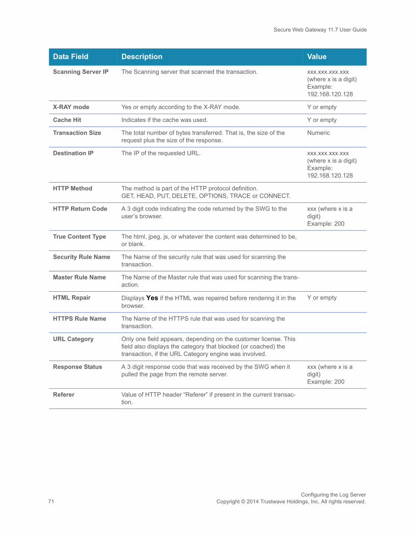
Secure Web Gateway 11.7 User Guide
Scanning Server IP The Scanning server that scanned the transaction. xxx.xxx.xxx.xxx (where x is a digit) Example: 192.168.120.128
X-RAY mode Yes or empty according to the X-RAY mode. Y or empty
Cache Hit Indicates if the cache was used. Y or empty
Transaction Size The total number of bytes transferred. That is, the size of the request plus the size of the response.
Numeric
Destination IP The IP of the requested URL. xxx.xxx.xxx.xxx (where x is a digit) Example: 192.168.120.128
HTTP Method The method is part of the HTTP protocol definition. GET, HEAD, PUT, DELETE, OPTIONS, TRACE or CONNECT.
HTTP Return Code A 3 digit code indicating the code returned by the SWG to the user’s browser.
xxx (where x is a digit) Example: 200
True Content Type The html, jpeg, js, or whatever the content was determined to be, or blank.
Security Rule Name The Name of the security rule that was used for scanning the transaction.
Master Rule Name The Name of the Master rule that was used for scanning the trans-action.
HTML Repair Displays Yes if the HTML was repaired before rendering it in the browser.
Y or empty
HTTPS Rule Name The Name of the HTTPS rule that was used for scanning the transaction.
URL Category Only one field appears, depending on the customer license. This field also displays the category that blocked (or coached) the transaction, if the URL Category engine was involved.
Response Status A 3 digit response code that was received by the SWG when it pulled the page from the remote server.
xxx (where x is a digit) Example: 200
Referer Value of HTTP header “Referer” if present in the current transac-tion.
Data Field Description Value
Configuring the Log Server71 Copyright © 2014 Trustwave Holdings, Inc. All rights reserved.

Secure Web Gateway 11.7 User Guide
3. Do either of the following:
• To have log messages sent to Archive, continue with To have Web Log messages sent to Archive:.
• If you have completed Log Configuration, click Save, and then if you are ready to distribute and implement the changes in your system devices, click .
To have Web Log messages sent to Archive:
An additional archiving option is to integrate SWG to Security Reporter (SR). For more information on integrating SWG with SR, see To connect SWG to Security Reporter via archiving:.
In the Log Archiving tab of the Log Properties screen, do the following:
1. Specify the Log Archiving Locations as follows. Repeat these steps for each Archive location:
a. Click the icon.
b. If archiving should be enabled to this Archive, select the Enable check box.
c. In the Connection Method field, select the method that the Log Server uses to connect to the Archive location:
• FTP — connect using regular File Transfer Protocol.
• FTP Passive — connect using File Transfer Protocol. This is where there is a firewall located between the Policy Server and the remote FTP site.
• Samba — connect using Server Message Block (SMB) communication protocol.
• SFTP — connect using Secure File Transfer Protocol.
Ensure that the Send To: Archive check box is selected in the Logging Policy rules for logging information to be sent to Archive, and that logging policy is assigned to users. If a rule’s Archive check box is not selected, its logging information will not be sent to archive.
To verify that Send To: Archive is selected, see To define a rule in a Logging policy:.
Configuring the Log ServerCopyright © 2014 Trustwave Holdings, Inc. All rights reserved. 72

Secure Web Gateway 11.7 User Guide
d. Specify the Archive file Location, the User Name, and the Password. The format of these values that you specify depends on the connection method:
2. Select the Archive Format:
• Extended — includes all available information on each logged transaction. Required when work-ing with Trustwave Security Reporter.
• Basic — includes only a subset of details on each logged transaction.
For more details on each format, see the SWG Management Console Reference Guide.
3. To have the Archive location tested when you save the definition, select the Test location settings on next save check box. Otherwise, ensure that the check box is cleared.
4. In the Log Archive Scheduling area, specify when archiving should be performed. You can specify a daily time or an interval between archive processing.
5. Do either of the following:
• To have log messages sent to Archive, continue with To enable and configure log retention:.
• If you have completed Log Configuration, click Save, and then if you are ready to distribute and implement the changes in your system devices, click .
Connection Method Archive Location Format, User Name and Password
FTP, FTP Passive, or SFTP
Archive Location format is:• For FTP or FTP Passive: <server_ip_address>/dir (for example,
10.194.5.104/Sarah_FTP).
• For SFTP: <server_ip_address> (for example, 10.194.5.104/).
User to connect with is the user name used when connecting to the Archive Location.
Password should be the password of the above user.
Samba Archive Location must include the server IP address and directory for your selected location, in the following format:
//<server_ip_address>/dir, (for example, //192.168.1.10/archive).
User to connect with must include the workgroup name and the user name used when connecting to the Archive Location, in the following format: workgroup/user, for example, marketing/nicole.
Password should be the password of the above user.
Configuring the Log Server73 Copyright © 2014 Trustwave Holdings, Inc. All rights reserved.

Secure Web Gateway 11.7 User Guide
To connect SWG to Security Reporter via archiving:
In addition to the SWG Internal Reporting Tool, Trustwave provides support for integration with the Security Reporter. The Security Reporter (SR) is an advanced external reporter offering organizational, security, and productivity reports.
1. Select Administration | System Settings | SWG Devices.
2. In the tree, under Devices, select Management Devices Group, then the default IP node, then Log Server, and then Log Properties.
3. Click Edit. The main window is opened for editing.
4. Click the Log Archiving tab.
5. In the Log Archiving Location area click to add a new entry row.
6. Complete the Security Reporter details in the new row.
7. In the Archive format list, select Extended Format.
8. Click Save.
9. If you are ready to distribute and implement the changes in your system devices, click .
To enable and configure log retention:
To enable log retention, do the following in the Web Log Retention tab of the Log Properties screen:
1. Select the Enable Web Log Retention check box.
2. In the Retention period field, specify the number of weeks that logs should be retained.
3. When you have completed Log Configuration, click Save.
4. If you are ready to distribute and implement the changes in your system devices, click .
To enable and configure Forensics:
The Forensics feature collects data such as transaction details and the description of threats gathered by the Entrapper engine when a transaction is blocked. The report is saved securely and can be accessed when required.
The Forensics tab of the Log Properties window is used to define and test the location of archived forensic reports and to define the password to open the zipped reports.
To enable Forensics, do the following in the Forensics tab of the Log Properties screen:
1. Select the Enable Forensics check box.
2. Enter the required fields as described in the table below.
3. When complete, click Save.
4. If you are ready to distribute and implement the changes, click .
Configuring the Log ServerCopyright © 2014 Trustwave Holdings, Inc. All rights reserved. 74

Secure Web Gateway 11.7 User Guide
Fields in the Forensics Tab
Field Description
Enable Log check box (at the top of the window)
To activate this functionality, ensure that this check box is selected.
Enable Forensics check box To activate use of Forensic reports, select this check box.
Forensics Location Define the details of where the Forensics report is saved in this area.
Connection Method
Select the method that the Log Server should use to connect to the Forensics location:
• FTP — Connect using regular File Transfer Protocol.
• FTP Passive — Connect using File Transfer Protocol (there is a firewall located between the Policy Server and the remote FTP site).
• Samba — Connect using Server Message Block (SMB) communication protocol.
• SFTP — Connect using Secure File Transfer Protocol.
User Name, Password, Location
The details for these fields depend on the selected Connection Method. For a description of these details, see Archive Location Format, User Name and Password.
Test Forensics Location on next save check box
To have the location tested when you save the definition, ensure this check box is selected; otherwise, ensure that the check box is cleared.
If you test the location, an attempt is made to send a test file to the forensic location. If the attempt fails, a message pops up. If the operation is successful, an Operation Succeeded message displays in the bar on the bottom left of the screen.
Forensic Files Archive Enter and confirm the password to open the saved report file.
Configuring the Log Server75 Copyright © 2014 Trustwave Holdings, Inc. All rights reserved.

Secure Web Gateway 11.7 User Guide
13 Configuring Alerts
Through the Alerts mechanism, SWG can notify you of system events, application events, update events, and security events. SWG can send alerts through two different communication channels, besides System Log messages: Email messages, and SNMP notification.
If alerts notification will go through SNMP, you must configure SNMP settings.
You can also enable and configure alert notifications if certain security thresholds are passed by incoming or outgoing traffic.
The task of configuring Alerts consists of the following procedures:
• Assigning Alert Channels to Event Types
• Configuring SNMP Settings
• Setting Thresholds for Security Alert Notifications
13.1 Assigning Alert Channels to Event TypesTo assign Alert Channels to Event Types:
1. Select Administration | Alerts | Alert Settings.
The Alert Settings window is displayed.
2. Click Edit.
3. For each type of Event, check the type of alert notification, SNMP and/or Email, that should be sent.
4. For each event type for which you requested email alerts, specify the target email address. To specify
more than one email address for an event type, click the icon, and select Add Row.
5. Click Save.
6. To distribute and implement the changes in your system devices, click .
Administrators can view Alerts sent via SNMP in the Dashboard, accessed by clicking
the icon. For more information, see the SWG Management Console Reference
Guide.
For Email alerts to be sent, you must configure the Mail Server, including selecting the Enable Sending Email check box. For instructions, see Configuring the Mail Server.
For SNMP alerts to be sent, you must configure SNMP settings, including selecting the Enable Trap Sending check box. For instructions, see Configuring SNMP Settings.
Configuring Alerts75 Copyright © 2015 Trustwave Holdings, Inc. All rights reserved.

Secure Web Gateway 11.7 User Guide
13.2 Configuring SNMP SettingsIf you are sending SNMP alerts, you must configure SNMP settings.
To configure SNMP settings:
1. Select Administration | Alerts | SNMP Settings.
The General tab of the SNMP Settings window is displayed.
In this tab, you configure the SNMP protocol for MIB monitoring/Trap sending, as well as the ports. Youalso configure the Hostname/IP destination servers for receiving the SNMP traps.
2. Click Edit.
3. To enable SWG to perform MIB monitoring:
a. Ensure that the Enable MIB Monitoring check box is selected.
b. In the Listening Port (input) field, specify the port against which SWG should perform SNMP queries. The default port is 161.
4. To enable SWG to send traps:
a. Ensure that the Enable Trap Sending check box is selected.
b. In the Trap Port (output) field, specify the corresponding Trap Port. The default port is 162.
5. If the Policy server should be the Trap Destination Server, select the Set Policy Server as Trap Destination Server check box.
6. In the three entry fields to the right of associated check boxes, optionally specify up to three possible destination servers. Note: If the device is set up to query a Domain Name System (DNS) server, you are permitted to specify a host name instead of an IP address for the trap destination.To have the traps sent to any or all of these servers, select the check box beside the server.
7. Select the SNMP Version tab. In this tab, you select with which version of SNMP the system will work, and define any needed parameters.
8. Choose the SNMP version, and do one of the following as appropriate:
• If you chose SNMPv2, in the Community field define the group to which the devices and manage-ment stations running SNMP belong. The default string is “Trustwave”. Then skip to Step 10.
Configuring AlertsCopyright © 2015 Trustwave Holdings, Inc. All rights reserved. 76
Secure Web Gateway 11.7 User Guide
• If you chose SNPMv3, do the following:
a. Define the SNMP MIB Monitoring parameters, as follows.
i. In the Security Name field, specify the SNMP user name.
ii. In the Security Level field, select whether the messages should be sent unauthenticated (None), authenticated, or authenticated and encrypted.
iii. If you specified that the messages should be sent unauthenticated, that is, you specified None, skip to Step b below; otherwise, enter the remaining parameters in the SNMP MIB Monitoring area as instructed in the following sub-steps.
iv. In the Authentication Protocol field, select the Authentication Protocol — either verification checksums MD5 or SHA.
v. In the Authentication Key field, specify the user’s authentication key, which signs the message being sent. There is a minimum 8 character requirement.
vi. In the Encryption Key field, specify the user’s encryption key, which encrypts the data portion of the message being sent. There is a minimum 8 character requirement.
b. Define the SNMP Traps parameters, by doing either of the following:
• To supply the same Security parameters (name, level, etc.) for SNMP Traps that you used for MIB Monitoring, select the Use SNMP MIB Monitoring information check box.
• Otherwise, enter a Security name, Security level, Authentication Protocol, Authentication Key and Encryption Key for SNMP Traps. The same as MIB Monitoring in Step 8a.
9. To test that the traps are successfully sent to the SNMP servers, click the Test button in the General tab. A test message will be sent to the defined server with the SNMP name, IP and SWG Software Version.
10. Click Save.
11. If you are ready to distribute and implement the changes in your system devices, click .
The Monitoring parameters define the security protocol and encryption methods used to obtain information from the SNMP agent on the machine. The information retrieved is part of a MIB.
The encryption mode or privacy protocol used is DES encryption algorithm.
SNMPv3 mandates that trap messages are rejected unless the SNMPv3 user sending the trap already exists in the user database. The user database in an SNMPv3 application is referenced by a combination of the user's name or Security Name, and an automatically supplied identifier for the given SNMP application or engineID.
Configuring Alerts77 Copyright © 2015 Trustwave Holdings, Inc. All rights reserved.
Secure Web Gateway 11.7 User Guide
13.3 Setting Thresholds for Security Alert NotificationsYou can have administrators alerted when blocked incoming events such as Malicious Activities, Viruses, Scripts, and Binary Content, and/or blocked outgoing events such as URL Categorization, URL Lists, and Blocked Files according to file types, reach certain thresholds.
To set security thresholds for Alert Notifications:
1. Select Administration | Alerts | Security Alerts Settings.
2. In the Security Alerts Settings screen, click Edit.
3. Select the Enable Security Alerts When check box.
4. To enable alerts based on incoming traffic, select the check box dealing with incoming traffic notification and specify the following blocked incoming traffic figures:
• alert-triggering percentage — the amount of blocked incoming traffic, as a percentage of total incoming traffic, that will trigger an alert.
• minutes — the number of minutes over which the percentages should be measured.
• alert-clearing percentage — the amount of blocked incoming traffic, as a percentage of total incoming traffic, below which the alert will be cleared, and it must be lower than the alert-triggering percentage.
5. To enable alerts based on outgoing traffic, select the check box dealing with outgoing traffic notification and specify the following blocked outgoing traffic figures:
• alert-triggering percentage — the amount of blocked outgoing traffic, as a percentage of total outgoing traffic, that will trigger an alert.
• minutes — the number of minutes over which the percentages should be measured.
• alert-clearing percentage — the amount of blocked outgoing traffic, as a percentage of total out-going traffic, below which the alert will be cleared, and it must be lower than the alert-triggering percentage.
6. Click Save.
7. If you are ready to distribute and implement the changes in your system devices, click .
An average percentage of blocked incoming events would be approximately 1%-5%. Above 7% percent of blocked data might indicate that there is some kind of security breach.
Configuring AlertsCopyright © 2015 Trustwave Holdings, Inc. All rights reserved. 78
Secure Web Gateway 11.7 User Guide
PART 5: Performing Monitoring and Maintenance79 Copyright © 2015 Trustwave Holdings, Inc. All rights reserved.
PART 5: Performing Monitoring and Maintenance
This part contains the following chapters and procedures:
• Chapter 14: Viewing Security and Component Statuses
• Chapter 15: Viewing Logs
• Chapter 16: Viewing and Working With Reports
• Chapter 17: Maintaining Your System
Secure Web Gateway 11.7 User Guide
14 Viewing Security and Component Statuses
The Dashboard enables you to view security status information at a glance. In addition, the configuration screens for some components allow you to view certain dynamic information about the components.
This chapter contains the following topics:
• Viewing Security Status Information (Dashboard)
• Viewing Dynamic Component Information
14.1 Viewing Security Status Information (Dashboard)To view Security Status information at a glance:
1. Click in the toolbar to display the Dashboard.
2. In the title bar of the Performance area, select the device and time period for which you want to display the information. The values you select affect the other graphs displayed in the window.
3. Alternatively, you can adjust the time period by moving the period slider that appears in a number of graphs. The time period can range from as far back as the last 12 months, or as recently as the last 12 hours.
4. To display details about the threat level, click the Threat Level link under the threat level gauge.
5. To display additional utilization details for a device, click the More Information button for the device in the Device Utilization area.
For information about the gauges and graphs in the Dashboard, see the SWG Management Console
Reference Guide.
If the Updates Available icon in the Dashboard toolbar is enabled, there are Security or other updates for your system. You should download them from Administration | Updates and Upgrades | Management. For more information, see Viewing and Installing Updates.
The button is red if alert messages are available for the device; otherwise, the button is green.
Viewing Security and Component StatusesCopyright © 2015 Trustwave Holdings, Inc. All rights reserved. 80

Secure Web Gateway 11.7 User Guide
14.2 Viewing Dynamic Component InformationThe following table lists the components for which you can view dynamic information, what information is displayed, and where and how to access it. For descriptions of the displayed information, see the SWG Management Console Reference Guide.
Component Information Displayed How to Access
Device — status Sync status, Connection Status, Committing Status, Last connection time, and Device Role and Activity Status
Select Administration | System Settings | SWG Devices.
In the Devices tree, click the device. Information is displayed in the Status tab.
Logs —Web, System and Audit
See Viewing Logs See Viewing Logs.
Scanning Engine
URL Filtering (Trustwave, IBM, Websense)
Version, DAT version Select Administration | System Settings | Scanning | Scanning Engines.
In the Scanning Engine tree, click the engine.
Lists of Available Updates and Installed Updates
Status, type, release date and time, description
Select Administration | Updates and Upgrades | Management. For more instructions, see Viewing and Installing Updates.
System Info:
General
Licensed Modules
Installed Components
Appliance MAC, Licensed seats, Licensed virtual cores, license expiration
List of modules
Component List, Version, Release Date, Install date
Select Administration | System Information.
Viewing Security and Component Statuses81 Copyright © 2015 Trustwave Holdings, Inc. All rights reserved.

Secure Web Gateway 11.7 User Guide
15 Viewing Logs
The Log Server logs all transactions, according to the configuration settings that you define.
When viewing a log, you can perform a search for relevant IDs or other parameter values. You can also create filters, and create, edit, and manage views for each log type.
There are three types of logs:
• Web Logs — record Web-surfing transactions of users in your network, according to your logging policy.
• System Logs — record events that have taken place in the system, for example, updates that have been installed, a module that is not responding, and so on.
• Audit Logs — record all changes made or actions taken from the Management Console, including tracking the creation of and changes to, policies, as well as system configuration.
This chapter contains the following topics:
• Viewing Logs
• Creating, Editing, and Managing Log Views
• Viewing Transaction Details (Web Log only)
15.1 Viewing Logs Each log type comes with one or more pre-defined views, which define which log data columns to display and filtering specifications for each log entry.
The information displayed in each column for the log entries is generally self-explanatory. For a detailed description of the data, see the SWG Management Console Reference Guide.
To view a log:
1. Choose Logs and Reports | <logtype>.
2. If more than one view is available, select the required view.
You cannot edit a pre-supplied default Log view. However, you can duplicate such a view and edit the duplicate; you can also create a Log view from scratch. See Creating, Editing, and Managing Log Views.
• In the displayed table, drag and drop column headers to change their order according to your viewing preferences.
• To adjust the width of a column to fully view the contents or the header name, double-click the column header.
• Optionally, you can display a different view by changing the columns displayed and the filtering of the current display. See Creating, Editing, and Managing Log Views.
Viewing LogsCopyright © 2015 Trustwave Holdings, Inc. All rights reserved. 82
Secure Web Gateway 11.7 User Guide
3. For System and Audit Logs only:
a. To find a specific log entry, specify a search parameter type and value in the Find By fields. For System and Audit logs, you can specify a Log ID or Device IP.
b. Click Apply.
• To re-display the full display, click in the parameter value field.
4. For Web Logs only:
a. To find a specific log entry, specify a search parameter type and value in the Find By fields. For Web logs, you can specify a Transaction ID, Client IP address, SWG or other Authenticated User name, or URL Category.
b. To display the logs of a different Admin Group, select the Admin Group. Note that you must have permissions to see the logs of the group.
c. To limit the Web log display to a specific time frame, either select a time frame value in the drop down list, or select a Date Range.
d. Click Apply.
• To re-display the full display, click .
• To display the details of a Web Log only transaction, see Viewing Transaction Details (Web Log only).
• To add a URL that appears in a Web log entry to the URL list, click the icon for the particular entry, and choose Add to URL List. This will enable it to be blocked or allowed in the User policy.
• To delete all current log entries in the Log table, click and select Log Cleanup.
Caution: You cannot stop or reverse Log Cleanup once you request it.
Viewing Logs83 Copyright © 2015 Trustwave Holdings, Inc. All rights reserved.
Secure Web Gateway 11.7 User Guide
15.2 Creating, Editing, and Managing Log ViewsA View defines which columns to display in the Log view, and filtering specifications for each log entry. Each Web, System, and Audit log type comes with one or more default profiles. You can define additional profiles.
To create or edit a log view:
1. Select Logs and Reports | <logtype>.
2. Do either of the following:
• To create a view, select the Views root in the tree and click Add View on the left of the tree, or right-click the Views root in the tree and choose Add View.
• To edit an existing view, click View Settings on the left of the tree, or right-click the view in the tree and select View Settings. Then click Edit.
3. Enter or edit the name for the view. You can optionally add a description.
The Profile definition screen contains two tabs:
• General — determines which data columns will be displayed.
• Filter — sets filtering criteria for the data
4. In the General tab, define which data will be displayed as follows:
a. If applicable, set the refresh interval in seconds.
b. Set the number of entries to display. The maximum number of entries is 100.
c. Select the check boxes of the data columns that you want displayed.
The list of data columns varies with the type of log you are defining.
Viewing LogsCopyright © 2015 Trustwave Holdings, Inc. All rights reserved. 84
Secure Web Gateway 11.7 User Guide
5. In the Filter tab, define filtering criteria as follows:
a. To add a new row, click in the header row and select Add Filter.
b. In the Field drop down list, select the required filter type.
c. In the Operator drop down list, select the relevant parameter (for example, Equals). The Operator drop down list varies according to the selected filter type.
d. Depending on your selections, the Value field displays either a drop down list or a blank field.
e. Select or specify a value in the Value field to complete your initial filter selection.
f. To define multiple filter criteria:
i. If an Or relationship is needed between any of the filters, click Switch to Advanced mode.
ii. Repeat steps Step a through Step f for each filter. If you are in Advanced mode, be sure to select the appropriate relationship operators, and add any needed parentheses.
g. To delete a filtering row, click the icon if it is displayed. Otherwise, click the icon of the row, and choose Delete Filter.
6. Click Save.
At the bottom of the Filter tab is a toggle button Switch To Advanced mode | Switch To Simple mode.• Simple Mode, which is the default mode, is useful when you define either a single filter, or
when you define multiple filters that all have an AND relationship. This mode:
• allows only AND relational operators; it does not allow OR operators.• does not display parentheses columns for defining complex relationships.• displays a Delete icon to the left of the Filter definition.
• Advanced Mode is useful when you are defining multiple filters having at least one OR relationship. This mode:
• allows specification of AND and OR operators.• displays parentheses columns for defining complex relationships.
The procedures for defining filters for Logs and for Reports are very similar.
A filter with parentheses cannot be switched back to Simple mode.
Viewing Logs85 Copyright © 2015 Trustwave Holdings, Inc. All rights reserved.
Secure Web Gateway 11.7 User Guide
15.3 Viewing Transaction Details (Web Log only)To view the transaction details of an entry in the Web Log:
1. In the Web Logs display, click the icon or double-click the selected transaction for the particular entry, and choose Details or Open in a new window.
The Transaction Entry Details window is displayed. The window contains a number of tabs, Transac-tion, User, Policy, and so on, that display information related to the transaction. For an explanation ofthe information displayed in the tabs, see the SWG Management Console Reference Guide.
The transaction is automatically scanned for Request and Response details, and if found, the typesRequest and/or Response are displayed in the tree under the Detail root.
2. To display the details of a request or response, select the Request or Response entry that is in the tree.
3. If you opened the Details display in the same window as the Web log, to return to the log, click Back.
Viewing LogsCopyright © 2015 Trustwave Holdings, Inc. All rights reserved. 86
Secure Web Gateway 11.7 User Guide
16 Viewing and Working With Reports
The Trustwave Reporting Tool comes with a number of predefined reports that enable enterprises to analyze the activity and performance of the SWG system based on data stored in the Reports database.
This chapter contains the following topics:
• Running and Viewing Reports
• Creating or Modifying Report Definitions
• Managing Reports
16.1 Running and Viewing ReportsYou can run reports on demand — that is, at any time, as needed. You can also define regular schedules for running reports. For details, see Defining Report Schedules.
To run a report on demand:
1. Select Logs and Reports | Reporting Tool | Reports.
2. Expand the tree of report types as needed and locate the report name; if you previously added it to your Favorites folder in the tree, you can find it there. For instructions on adding a report to the Favorites folder, see Adding Report Shortcuts to the Favorites Folder.
3. Right-click the report in the tree or Favorites folder, and choose Run Report.
4. In the main window, modify any parameters as needed, according to the following steps:
5. In the General tab:
a. Make any desired changes to the report format in the View As, Name and Description fields.
b. To save the report run results in the report’s History, ensure that the Run in Background check box is selected. If this check box is not selected, the results are not automatically saved.
6. To change which columns are displayed in the report, and/or the report filtering criteria, make the changes in the Columns and Filters tabs. For instructions, see Creating or Modifying Report Definitions.
7. Click the Run Report button at the bottom of the main window.
• If the Run in Background check box was NOT selected, the results of the report run are dis-played in a report window. To print or export the report, right-click the report and choose the desired action.
• If the Run in Background check box was selected, to view the report you must access the Report History. For instructions, see Viewing a Report’s History.
Viewing and Working With Reports87 Copyright © 2015 Trustwave Holdings, Inc. All rights reserved.

Secure Web Gateway 11.7 User Guide
16.2 Creating or Modifying Report DefinitionsSWG comes with a number of predefined reports, listed by category in the Reports tree.
You can, of course, run a report as is. But you also can edit the definition of any report before running it, or duplicate a report and edit the definition of the duplicate, enabling you to define as many versions of the report as will be useful.
To create a report or modify an existing report:
1. Select Logs and Reports | Reporting Tool | Reports.
The Reports tree displays the list of report categories. Under each category are the currently existingreports of that type.
2. Do either of the following:
• To edit the attributes of an existing report in the tree, select the report in the tree and when its attri-butes are displayed in the main window, click Edit.
• To create a report, right-click a similar report and select Duplicate Report.
The Report definition details appear in the main window. The definition consists of three tabs: General,Columns, and Filters.
3. In the General tab, define the general details about the report: Name, Description, and format in the View As field.
4. In the Columns tab, select the data columns that should be displayed in the report.
5. In the Filters tab, define filtering criteria as follows:
a. To add a new row, click , and select Add Filter.
b. In the Field drop down list, select the required filter type.
c. In the Operator drop down list, select the relevant parameter (for example, Equals). Note that the Operator drop down list varies according to the selected filter type.
Depending on your selections, the Value field displays either a drop down list or a blank field.
At the bottom of the Filters tab is a toggle button Switch To Advanced mode | Switch To Simple mode.• Simple Mode, which is the default mode, is useful when you define either a single filter, or
when you define multiple filters that all have an AND relationship. This mode:
• allows only AND relational operators; it does not allow OR operators.• does not display parentheses columns for defining complex relationships.• displays a Delete icon to the left of the Filter definition.
• Advanced Mode is useful when you are defining multiple filters having at least on OR relationship. This mode:
• allows specification of AND and OR operators.• display parentheses columns for defining complex relationships.
The procedures for defining filters for Logs and for Reports are very similar.
Viewing and Working With ReportsCopyright © 2015 Trustwave Holdings, Inc. All rights reserved. 88
Secure Web Gateway 11.7 User Guide
d. Select or specify a value in the Value field to complete your initial filter selection.
e. To define multiple filter criteria:
i. If an Or relationship is needed between any of the filters, click Switch to Advanced Mode.
ii. Repeat steps Step a through Step d for each filter. If you are in Advanced mode, be sure to select the appropriate relationship operators, and add any needed parentheses.
f. To delete a filtering row, click the icon if it is displayed. Otherwise, click the icon of the row, and choose Delete Filter.
6. Click Save.
16.3 Managing ReportsThis topic include procedures for the following:
• Defining Report Schedules
• Adding Report Shortcuts to the Favorites Folder
• Viewing a Report’s History
• Exporting Reports
16.3.1 Defining Report SchedulesYou can define multiple schedules for any report. When you define the schedule, you can also modify which columns are displayed and the filtering criteria, as part of the schedule.
When you define a schedule for a report, it appears in the tree under the report name.
To define a schedule for a report:
1. Do either of the following:
• To define a new schedule, right-click the report name and choose Add New Schedule.
• To modify an existing schedule, click the schedule name under the report name in the tree, and in the main window, click Edit.
The Scheduling dialog box is displayed. It contains the following tabs: Report Schedule, Report Tar-get, Columns, and Report Parameters.
2. Specify a name for the report schedule in the Schedule Name field. Specifying a name is mandatory.
3. To activate the report schedule you are defining, select the Enable Scheduling check box at the top of the screen. To suspend the automatic report scheduling for any reason, clear the check box.
A filter with parentheses cannot be switched back to Simple mode.
Viewing and Working With Reports89 Copyright © 2015 Trustwave Holdings, Inc. All rights reserved.

Secure Web Gateway 11.7 User Guide
4. In the Report Schedule tab, define the actual schedule. You can specify any combination of the following scheduling criteria, though you must specify at least one set of criteria:
• run the report once at a specified date and time.
• run the report daily, weekly, and/or monthly, at the specified times.
5. In the Report Target tab, which allows you to send the report to one or more recipients, specify the following information:
a. If the report should be stored on the appliance and appear in the Available Reports screen, select the Enable Available Reports check box. Note that there is a space limitation of 1 GB for locally saved reports and that older reports will be erased once this limit is reached.
b. If the report should be exported to the network location defined in Exported Reports Location, select the Export report check box.
c. To email the report to specific recipients, select the Email to check box, and for each recipient, click the icon and specify the email address.
6. In the Columns tab, ensure that only the data items that should be in the report are selected.
7. In the Report Parameters tab, define the filtering criteria as follows. Note that this tab is very similar to the Filters tab in the Report definition, and works in essentially the same way:
a. To add a new row, click . If a popup menu appears, select Add Filter.
b. In the Field drop down list, select the required filter type.
c. In the Operator drop down list, select the relevant parameter (for example, Equals). The Operator drop down list varies according to the selected filter type.
Depending on your selections, the Value field displays either a drop down list or a blank field.
d. Select or specify a value in the Value field to complete your initial filter selection.
The icon is inactive and emails cannot be sent until mail server configuration is complete. You can navigate to Administration | System Settings | Mail Server to complete the configuration.
At the bottom of the Filters tab is a toggle button Switch To Advanced mode | Switch To Simple mode.• Simple Mode, which is the default mode, is useful when you define either a single filter, or
when you define multiple filters that all have an AND relationship. This mode:
• allows only AND relational operators; it does not allow OR operators.• does not display parentheses columns for defining complex relationships.• displays a Delete icon to the left of the Filter definition.
• Advanced Mode is useful when you are defining multiple filters having at least on OR relationship. This mode:
• allows specification of AND and OR operators.• display parentheses columns for defining complex relationships.
The procedures for defining filters for Logs and for Reports are very similar.
Viewing and Working With ReportsCopyright © 2015 Trustwave Holdings, Inc. All rights reserved. 90

Secure Web Gateway 11.7 User Guide
e. To define multiple filter criteria:
i. If an Or relationship is needed between any of the filters, click Switch to Advanced mode.
ii. Repeat steps Step a through Step d for each filter. If you are in Advanced mode, be sure to select the appropriate relationship operators, and add any needed parentheses.
f. To delete a filtering row, click the icon if it is displayed. Otherwise, click the icon of the row, and choose Delete Filter.
8. Click Save.
16.3.2 Adding Report Shortcuts to the Favorites FolderThe Favorites folder serves as a repository for a selected group of reports created per Policy Server. It is designed to enable the administrator to view, schedule, or delete frequently-used reports without scrolling through all Report Categories.
To add a report shortcut to the Favorites folder
1. If you are not already there, navigate to Logs and Reports | Reporting Tool | Reports.
2. Find the report in its category, and then right-click the report and choose Add to Favorites.
3. Clicking the report link in the Favorites folder will open the report editing screen, which provides all the same functionality used to configure original reports such as; Filters, Columns, and General report information.
4. To remove a report from the Favorites folder, right-click the report in the Favorites folder, and choose Remove from Favorites.
16.3.3 Viewing a Report’s HistoryThe history of scheduled report runs is automatically saved.
You can also save the history of a report that you run on demand by running the report as a background process.
You can then view the report’s history and any report saved in that history. The History screen provides the following report run details: Name, Recurrence, Status, Date, Time, and Format.
To view a report’s history:
1. If it is not already selected, select Logs and Reports | Reporting Tool | Reports.
2. Do either of the following:
• To display the full report history, right-click the report either in the tree or in the Favorites folder, and choose History.
A filter with parentheses cannot be switched back to Simple mode.
Viewing and Working With Reports91 Copyright © 2015 Trustwave Holdings, Inc. All rights reserved.

Secure Web Gateway 11.7 User Guide
• To display the list of reports generated from a particular schedule of the report, right-click the schedule and choose History.
The History window provides report details such as Name, Recurrence, Status, and so on.
3. To view an actual report run from the history, click the icon for the specific run, and choose Show Report. The report opens in a new window.
16.3.4 Exporting ReportsYou can manually export reports that are currently open in a Report window. This applies to reports that were run on demand, and to reports that you opened from the History file.
You can also define that scheduled reports be automatically exported. As part of this definition process, you must first define the Exported Reports Location. This requires that you choose a connection method. The chosen connection method, in turn, determines the content used to define your Report Location, User to connect with and Password fields
This section contains the following procedures:
• To manually export a currently-opened HTML report
• To define automatic export of a scheduled report:
• To define the Exported Reports Location:
To manually export a currently-opened HTML report
1. Place the cursor in the report area. A toolbar providing additional options is displayed.
2. Click . A standard Windows Explorer window opens.
3. Save the file as needed.
To define automatic export of a scheduled report:
1. In the General tab of the report’s schedule, select the Export report check box, and save and commit the change.
2. Define the Exported Reports Location, as described below in To define the Exported Reports Location:
To define the Exported Reports Location:
1. Navigate to Logs and Reports | Reporting Tool | Exported Reports Location. The Exported Scheduled Reports Location window is displayed.
2. In the main window, click Edit.
3. In the Connection Method field, select the connection method. Possible values:
• FTP — connect using regular File Transfer Protocol.
• FTP Passive — connect using File Transfer Protocol where there is a firewall located between the Policy Server and the remote FTP site.
Viewing and Working With ReportsCopyright © 2015 Trustwave Holdings, Inc. All rights reserved. 92
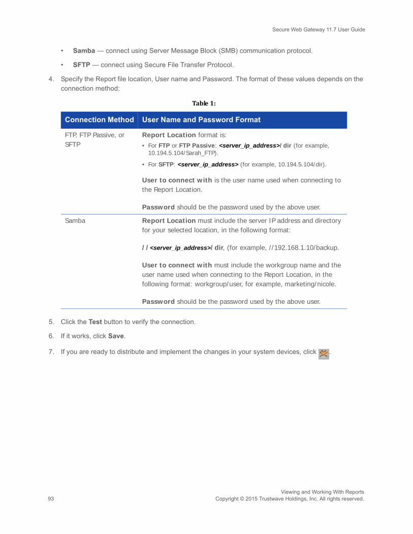
Secure Web Gateway 11.7 User Guide
• Samba — connect using Server Message Block (SMB) communication protocol.
• SFTP — connect using Secure File Transfer Protocol.
4. Specify the Report file location, User name and Password. The format of these values depends on the connection method:
5. Click the Test button to verify the connection.
6. If it works, click Save.
7. If you are ready to distribute and implement the changes in your system devices, click .
Table1:
Connection Method User Name and Password Format
FTP, FTP Passive, or SFTP
Report Location format is:• For FTP or FTP Passive: <server_ip_address>/dir (for example,
10.194.5.104/Sarah_FTP).
• For SFTP: <server_ip_address> (for example, 10.194.5.104/dir).
User to connect with is the user name used when connecting to the Report Location.
Password should be the password used by the above user.
Samba Report Location must include the server IP address and directory for your selected location, in the following format:
//<server_ip_address>/dir, (for example, //192.168.1.10/backup.
User to connect with must include the workgroup name and the user name used when connecting to the Report Location, in the following format: workgroup/user, for example, marketing/nicole.
Password should be the password used by the above user.
Viewing and Working With Reports93 Copyright © 2015 Trustwave Holdings, Inc. All rights reserved.

Secure Web Gateway 11.7 User Guide
17 Maintaining Your System
This section contains the following topics and procedures:
• Performing Manual Backup and Restore
• Viewing and Installing Updates
• Importing From and Exporting Policy Databases
17.1 Performing Manual Backup and RestoreThis section contains the following procedures:
• To manually backup your system:
• To restore a System backup:
• To manually backup your Reports database:
• To restore a Reports database backup:
To manually backup your system:
1. Select Administration | Policy Server DB Backup | Backup Now.
2. In the Backup Now window, specify a name or description for the backup file.
3. Click Backup.
To restore a System backup:
1. Select Administration | Policy Server DB Backup | Backup Restore.
2. In the Restore window, click Edit.
3. Click the icon next to the backup that to be restored, and select Restore from the drop down menu.
4. Confirm that you want to perform the restore.
To manually backup your Reports database:
1. Select Administration | Reports DB Backup | Backup Settings.
2. Ensure that the backup configuration parameters are set. See Configuring Backup Settings.
3. Click Backup Now.
Before performing backup, ensure that the backup settings have been configured. For instructions, see Configuring Backup Settings.
If you have implemented the High Availability Policy Server feature, you must disable it before performing a restore.
Maintaining Your SystemCopyright © 2015 Trustwave Holdings, Inc. All rights reserved. 94
Secure Web Gateway 11.7 User Guide
To restore a Reports database backup:
1. Select Administration | Reports DB Backup | Backup Restore.
2. In the Restore window, click Edit.
3. Click the icon next to the backup to be restored, and select Restore from the drop down menu.
A confirmation prompt with the following message will appear: “Clicking restore will overwrite any pre-existing partition. Are you sure you want to restore this partition?”
4. Click OK in response to the Confirmation prompt.
The Reports data will be restored to the system.
5. To verify that the operation was successful, check the System log.
17.2 Viewing and Installing UpdatesIn the Updates Management window, you can:
• view the list of updates available for installation, and upload and install the updates, as needed
• view the list of updates which are already installed
• generate a key, if needed for downloading updates
This section contains the following procedures:
• To upload and/or install an update:
• To view the list of installed updates:
• To generate a download key:
To upload and/or install an update:
1. Select Administration | Updates and Upgrades | Management.
The Updates Management window displays the list of available updates in the Available Updates tab.
The following icons in the Status column indicates the retrieval status of the available updates:
— indicates that an available update has been retrieved successfully.
— indicates that an available update is in the process of being uploaded/installed.
— indicates that an upload/install has failed.
The Generate a Key feature is intended for customers who use the appliance in an isolated network not connected to the Internet, and who must instead download updates using an Offline Updates application. For more information on Offline Updates, contact your Trustwave representativeand/or refer to the Offline Updates Technical Brief.
Maintaining Your System95 Copyright © 2015 Trustwave Holdings, Inc. All rights reserved.
Secure Web Gateway 11.7 User Guide
2. To upload an update, do either of the following as appropriate:
• If you are working remotely, click the Retrieve Updates button. It might take some time for the updates to be retrieved.
• To upload local updates, do the following:
i. Click Import Updates.
ii. In the displayed Import Local Update dialog box, click Browse and browse to the local location containing the updates provided by Trustwave.
iii. Click Import.
3. To view relevant details about an update, click the icon next to the update.
4. To install an update, click next to the update, and select Install Now.
The Status icon for the update will change as the install progresses. Once the update is installed, it isremoved from the Available Updates tab and is displayed in the Installed Updates tab.
To view the list of installed updates:
1. Select Administration | Updates and Upgrades | Management.
2. Display the Installed Updates tab. The tab lists both automatically installed and manually installed updates.
3. To view relevant details about an update, click the icon next to the update.
To generate a download key:
1. Select Administration | Updates and Upgrades | Management.
2. Select the Update Key tab.
3. Click Generate Key.
The key is generated and appears in the tab. This feature requires that you have a special license touse the Offline Update application.
17.3 Importing From and Exporting Policy DatabasesAdministrators can export Security, HTTPS, Identification and Logging policy databases on a Policy Server to a file. They can then import policies, rules, conditions, and condition options from the exported database file into another Policy server. This only refers to administrator-created Policies, Rules and Conditions, not to Trustwave default Policies, Rules and Conditions.
If you are using Internet Explorer, you can copy the key to the clipboard. Firefox users do not have this option.
Maintaining Your SystemCopyright © 2015 Trustwave Holdings, Inc. All rights reserved. 96

Secure Web Gateway 11.7 User Guide
When exporting, the exported files are encrypted and saved to a location specified by the administrator such as the local disk or network drive.
When importing items that have the same name as existing items, to avoid potential conflicts, you can choose to leave the existing items in place. overwrite existing items, or save the imported items under different names.
This task contains the following procedures:
• To export a policy database to a file:
• To import policies, rules, and conditions from an exported database file:
• To import condition options from an exported database file:
To export a policy database to a file:
1. Select Administration | Export/Import | Export.
The File Download message appears.
2. Click Save and choose the location to save this file.
To import policies, rules, and conditions from an exported database file:
1. Select Administration | Export/Import | Import.
The Import window is displayed.
2. Select the exported database file, as follows:
a. In the tree pane, right-click the Database Files (root) entry, and choose Import Policies.
Alternatively, you can click the icon to the left of the Database Files entry.
b. In the Import Policy screen, click Browse and select the file to be imported.
c. Click Import. The nodes for import appear in the Import Policies tree.
3. Select and import the policy as follows:
a. Expand the tree pane, right-click the policy that you want to import and choose Import.
The policy import window is displayed.
b. Select the desired action:
• To change one or more policy conditions while leaving the remaining unchanged, choose Leave original.
• To completely overwrite the existing policy with the imported policy having the same name, choose Overwrite.
Items for which the administrator does not have write permissions will not be exported.
Maintaining Your System97 Copyright © 2015 Trustwave Holdings, Inc. All rights reserved.

Secure Web Gateway 11.7 User Guide
• To rename the policy so as not to overwrite the existing policy with the same name, choose Rename, and specify the new name for the policy.
c. For individual conditions that are displayed in the Conditions table, select the desired actions where the same actions available for the policy in Step b are available for conditions.
d. If you chose to rename conditions, specify their new names in the New Component Name column.
e. Click OK.
4. If you are ready to distribute and implement the changes in your system devices, click .
To import condition options from an exported database file:
The procedure is used to import sets of condition options such as appear under Policies | Condition Elements; for example, File Extension lists and URL Lists, from an exported database file.
1. Select Administration | Export/Import | Import.
The Import window is displayed.
2. Expand the tree pane, right-click the condition that you want to import and choose Import.
The component import window is displayed.
3. Select the desired action:
• To leave the original conditions unchanged, choose Leave original.
• To overwrite the existing condition with the imported condition of the same name, choose Over-write.
• To rename the condition so as not to overwrite the condition with the same name, choose Rename, and specify the new name for the condition.
4. Click OK.
5. If you are ready to distribute and implement the changes in your system devices, click .
After importing any policy, be sure to check that it reflects the new licensed engine.
When importing a Condition from one Policy Server to another, if one of the components in the Condition does not exist on the target Policy Server, an error message is displayed. Depending on the cause, solve the problem as follows:• If Trustwave added a new component to a Trustwave predefined list, make sure that you
have the latest Security Update Version installed on the target Policy Server, and repeat the Import process.
• If a customer-defined list has an added component, save the list in the source Policy Server under a different name.
Maintaining Your SystemCopyright © 2015 Trustwave Holdings, Inc. All rights reserved. 98

Secure Web Gateway 11.7 User Guide
PART 6: Performing Advanced Configuration99 Copyright © 2015 Trustwave Holdings, Inc. All rights reserved.
PART 6: Performing Advanced Configuration
This part contains the following chapters and procedures:
• Chapter 18: Defining Administrators
• Chapter 19: Performing Additional Configuration Tasks
• Chapter 20: Enabling HTTPS Scanning
• Chapter 21: Implementing Cloud Security
• Chapter 22: Implementing ICAP

Secure Web Gateway 11.7 User Guide
18 Defining Administrators
SWG supports multiple administrators and administrator groups. Administrator groups are characterized by the permissions that they are granted to access different items (for example, Alert Settings, or Block and Warn messages). Administrators are automatically assigned the permissions of the group to which they belong.
At least one administrator must be designated as a Super Administrator. A Super Administrator is authenticated locally in the system even when RADIUS authentication is enabled, and has maximum allowable permissions. Super Administrators must belong to a predefined Super Administrators group.
If you are connected to a RADIUS Server, that server authenticates all administrators except Super Administrators. In this case, new administrators, that is, those not assigned to another group, are automatically placed in a group called the RADIUS Default Group.
If your site has implemented Master Policy usage, you can also assign a Master Policy to the Administrator Group.
This chapter contains the following sections:
• Creating/Editing an Administrator Group
• Creating/Editing an Administrator
• Setting Access Permissions
• Configuring RADIUS Server Authentication
18.1 Creating/Editing an Administrator GroupTo create or edit an Administrator Group:
1. Select Administration | Administrators.
2. Do either of the following:
• To create an Administrator Group: In the tree pane, select the Default Permissions (root) node, and click the icon. Alternatively, you can right-click the Default Permissions node, and choose Add Administrators Group. The Administrator Group details screen is displayed.
• To edit an existing Administrator Group: In the tree pane, select the group, and then, in the Admin-istrator Group Details screen, click Edit.
The Administrator Group Details screen has three tabs. The current tab is General.
3. Specify a Group Name, and optionally add any useful notes about this group that you want.
4. Select the appropriate check boxes for any desired password requirements and for expiration, set the number of days.
Defining AdministratorsCopyright © 2015 Trustwave Holdings, Inc. All rights reserved. 100

Secure Web Gateway 11.7 User Guide
Note that enforcing a secure password means that the password will have to satisfy at least 3 of thefollowing criteria:
• contains at least one uppercase alphabetic character (A-Z)
• contains at least one lowercase alphabetic character (a-z)
• contains at least one numeric character (0-9)
• contains at least one of the following characters !@#$%^&*( )
5. Edit the Permission definitions. For instructions, see Setting Access Permissions.
6. Click Save.
7. If you are ready to distribute and implement the changes in your system devices, click .
18.2 Creating/Editing an AdministratorTo create or edit an administrator:
1. Select Administration | Administrators.
2. Do either of the following:
• To create an Administrator: In the tree pane, select the Administrator Group to which the Adminis-trator should be added, and click the icon. Alternatively, you can right-click the administrator group, and choose Add Administrator. The New Administrator definition screen is displayed.
• To edit an existing Administrator definition: In the tree pane, select the administrator, and then, in the administrator’s definition screen, click Edit.
The Administrator definition screen has three tabs. The current tab is General.
3. Specify a name for the Administrator.
4. Enter or edit any desired General details of this administrator. Note the following:
• Regarding Master Policy: You should not change the Use Default Settings value unless you have a Master Policy assigned to the site and you want the administrator to use a different policy.
• For new administrators, except RADIUS administrators, you must assign and confirm a password.
• For RADIUS administrators, the Password field has no meaning. The field becomes a protected field so that you cannot enter a value once the RADIUS server is activated, as instructed in Step 4 in Configuring RADIUS Server Authentication.
If you plan to assign privileges higher than View Only to a new administrator who will be authenticated by a RADIUS server, it is recommended that you manually create that administrator in the appropriate Administrator group prior to the administrator’s first login.
Defining Administrators101 Copyright © 2015 Trustwave Holdings, Inc. All rights reserved.
Secure Web Gateway 11.7 User Guide
5. Edit the Permission definitions. For instructions, see Setting Access Permissions.
6. Click Save.
7. If you are ready to distribute and implement the changes in your system devices, click .
18.3 Setting Access PermissionsYou can assign access permissions using either the Categories View tab or the Grid View tab. The procedure is the same for both Administrator Group definitions and Administrator definitions.
• Assigning permissions using the Categories View tab:
• Assigning permissions using the Grid View tab:
Assigning permissions using the Categories View tab:
1. If the Administration Group or Administrator definition screen is not displayed:
a. Select Administration | Administrators.
b. In the tree pane, select the Administrator or Group for which you want to define access permissions.
c. In the main window, click Edit.
2. Select the Permissions - Categories View tab.
3. In the Category drop down list, select the appropriate category.
4. In the Sub-category drop down list, select the appropriate sub-category.
Depending on the selection, beneath the Category/Subcategory fields, the screen displays either:
• a table of object types/objects, or
• a set of two radio-button options. The first option keeps the default permissions; the second option lets you change the permissions.
5. If the set of radio button options is displayed, to change the permissions, select the second radio button and choose the desired permission.
6. If the a table of object types/objects is displayed:
a. Adjust the permissions for any object types as necessary by selecting the needed permission in the drop down list to the right of the object type. Note that when Default is the selected permission in the drop down list, the column to its right displays what the default value translates to (for example, = update).
It is recommended that the RADIUS Default Group be assigned View Only permissions, so that higher permissions are not granted to every administrator authenticated by the RADIUS server.
Defining AdministratorsCopyright © 2015 Trustwave Holdings, Inc. All rights reserved. 102

Secure Web Gateway 11.7 User Guide
b. If the object type has a icon next to it, click the icon to display the objects under it.
c. To assign an object a different permission than its object type, select the Override check box, and select the permission.
7. Repeat as necessary.
8. Click Save.
9. If you are ready to distribute and implement the changes in your system devices, click .
Assigning permissions using the Grid View tab:
1. If the Administration Group or Administrator definition screen is not displayed:
a. Select Administration | Administrators.
b. In the tree pane, select the Administrator or Group for which you want to define access permissions.
c. In the main window, click Edit.
2. Select the Permissions - Grid View tab.
3. Scroll to the desired class. If the Class has a icon next to it, click the icon to display the details under it.
The Default column displays the default permission value at each data level.
4. Where necessary, adjust the permission value, beginning with the highest data level, and then moving down data levels, by selecting the desired level in the Access column.
5. Repeat as necessary.
6. Click Save.
7. If you are ready to distribute and implement the changes in your system devices, click .
To allow Administrator Groups to view Web Logs for users belonging to other Administrator Groups, click Override and set View Access permission to the groups that should be granted permission, under Category: Logs and Reports, Sub Category: Web Log Admin Group / Objects created by Other Groups.
It is recommended that the RADIUS Default Group be assigned View Only permissions, so that higher permissions are not granted to every administrator authenticated by the RADIUS server.
To allow Administrator Groups to view Web Logs for users belonging to other Administrator Groups, set View Access permission to those groups that should be granted permission, under the Class: Web Log Admin Group / Sub Class: Others.
Defining Administrators103 Copyright © 2015 Trustwave Holdings, Inc. All rights reserved.

Secure Web Gateway 11.7 User Guide
18.4 Configuring RADIUS Server AuthenticationYou configure RADIUS Server Authentication on the Policy Server.
To configure the RADIUS Server connection and authentication:
1. Select Administration | System Settings | SWG Devices.
2. In the Devices tree, select Management Devices Group | <device_ip> | Policy Server | RADIUS Authentication.
3. In the RADIUS Authentication window, click Edit.
4. Select the Active check box.
5. According to your RADIUS server configuration, select the Authentication Method from the drop down menu.
6. In the Primary Authentication Host field, enter the host name, which is the server name or IP.
7. In the accompanying Port field, enter the RADIUS authentication port. This is the port on which the servers will communicate.
8. Optionally, enter Secondary Authentication host and port values.
9. In the Shared Secret field, enter a password to define a shared string to authenticate the client and the server.
10. Select a number from the Retry Limit drop down menu. For example, retry limit is 6 times.
11. Select a number from the Retry Interval drop down menu to define the interval, in seconds, between each attempt.
12. Click Save.
13. If you are ready to distribute and implement the changes in your system devices, click .
To ensure that the process runs efficiently, it is highly recommended that your SWG use NTP synchronization. For more information, refer to Limited Shell command in the SWG Setup Guide.
If your browser, specifically in IE6, freezes during login, you should try solving the problem by reducing the number of seconds set in the Retry Interval field.
Defining AdministratorsCopyright © 2015 Trustwave Holdings, Inc. All rights reserved. 104

Secure Web Gateway 11.7 User Guide
19 Performing Additional Configuration Tasks
This chapter includes the following configuration tasks and procedures:
• Adjusting Network Settings for a Device
• Configuring a Device to Use an NTP Server
• Enabling Dynamic URL Categorization
• Configuring Administrative Settings
• Importing Digital Certificates
• Configuring Backup Settings
• Configuring Automatic Update Handling
• Defining and Customizing Device Logging Policy
• Defining a Device Logging Policy
• Defining a Rule in a Device Logging Policy
• Configuring Default and Device-Specific Access Lists
• Configuring Transparent Proxy Mode
• Scheduling Configuration and Security Updates for Scanning Server Device Groups
• Implementing High Availability
• Implementing Disaster Recovery
• Modifying LDAP Directory Advanced Settings
19.1 Adjusting Network Settings for a DeviceThis procedure explains how to use the config_network Limited Shell command to modify a device’s network settings, such as IP addresses, routing information, and DNS parameters.
To adjust network settings for a device:
1. Log in to the Limited Shell. You can connect using either SSH client, serial cable, connecting keyboard and monitor or, in case of VM, vSphere client.
The Limited Shell works by prompting you to enter a value, often in response to displayed information.For example, it might display a numbered list and ask that you enter the number of the item you wantto choose; or it might request that you enter specific information.
2. At the prompt, enter the config_network command.
Once you have completed device setup in the Limited Shell, you should NOT use the setup Limited Shell command to make changes. Instead, you should use the config_network command, as instructed in this procedure.
Performing Additional Configuration Tasks105 Copyright © 2015 Trustwave Holdings, Inc. All rights reserved.

Secure Web Gateway 11.7 User Guide
The current network configuration is displayed. The following data is displayed:
• interfaces, and the status of each, Enabled or Disabled.
• DNS cache status, DNS Search Domain, and nameserver. A nameserver is a network server that provides a naming or directory service and Hostname configuration.
A prompt asks if you would like to change the configuration.
3. Enter y to change the network configuration.
The Limited Shell then displays several numbered options. The following table lists these options, anddescribes the edits that each option allows you to perform.
4. Depending on the action that you want to perform:
a. Enter the number of the main configure_network option.
b. At each successive prompt, enter the expected information, for example, item number or specific value.
c. To move back to the previous prompt, press Enter. This will enable you to perform additional actions before leaving the Limited Shell.
5. When you are done, enter q to quit the Limited Shell.
Option Edits you can perform from this option:
1. View none
2. Interface Choose a particular interface, and then:• Change, Add, or Remove its IP Address
• Add, Remove, or change its route. Format: <ip_address>/[<netmask>|<prefix>] via <prefix_ip>. For example: 1.1.1.1/32 via 10.0.3.
• Enable or Disable it.
3. Gateway Set/change the default gateway IP address. Format: <ip_address>/[<netmask>|<prefix>]. For example, 192.168.120.32/24.
Note: A default gateway is mandatory, and its IP address must be a local IP address.
4. DNS • Change DNS search domains
• Add or Remove DNS server.
Note: There must be a DNS Server that has the ability to resolve external IP addresses.
5. Hostname Configure the device’s hostname.
6. Hosts Configure the device’s host file.
Performing Additional Configuration TasksCopyright © 2015 Trustwave Holdings, Inc. All rights reserved. 106

Secure Web Gateway 11.7 User Guide
19.2 Configuring a Device to Use an NTP Server This procedure describes how to use the Limited Shell to configure a device to use an NTP server.
To configure a device to use an NTP Server:
1. Log in to the Limited Shell. You can connect using either SSH client, serial cable, connecting keyboard and monitor or, in case of VM, vSphere client.
2. Enter the config_time command.
A prompt is displayed asking if you would like to change the time configuration.
3. Enter y to change the time configuration. The screen displays a number of Time and Date configuration options.
4. Enter 3, the option for NTP server.
5. At the prompt to type in the NTP server, type in the URL of the NTP server that you want to use, and press Enter. A message confirms that the NTP Server is configured to the specified URL.
6. Enter q to exit.
The device is configured to use the specified NTP server.
19.3 Enabling Dynamic URL Categorization SWG can classify the content of URL pages using TextCensor in cases where the URL Categorization engine fails to classify them specifically.
To configure SWG to use dynamic URL categorization:
1. Select Administration | System Settings | Scanning | Scanning Engines.
2. In the tree, click URL Filtering and select the Enable dynamic URL categorization check box.
You can see if actions taken by SWG were as a result of Dynamic Categorization by checking the Web Logs. The Contents details tab will include the URL Category and whether the item was dynamically categorized.
For more information on URL Filtering, see the SWG Management Console Reference Guide.
Before exiting, you can make other changes to the Date and Time and/or Time Zone if needed, by entering the option number and then providing the details at the prompts.
If the Enable sending customer feedback information check box is selected (via Administration| System Settings | Administrative Settings), relevant dynamic categorization data will be provided to the Malware team at Trustwave for review.
Performing Additional Configuration Tasks107 Copyright © 2015 Trustwave Holdings, Inc. All rights reserved.

Secure Web Gateway 11.7 User Guide
19.4 Configuring Administrative SettingsThis procedure explains how the administrator can:
• Set the amount of idle time, in minutes, after which the current session times out and requires the user to re-log in.
• Force the administrator to provide a relevant comment to be sent to the Audit log whenever a configuration change is committed.
• Enable the automatic sending of blocked transaction and browsing habit data to the Trustwave SpiderLabs Research team, according to a specified schedule.
• Determine which icons to show in the Management Console toolbar.
To configure Administrative Settings:
1. Select Administration | System Settings | Administrative Settings.
2. Click Edit.
3. In the Administrative Settings screen, ensure the General tab is displayed.
4. In the Console Timeout field, set the number of idle minutes that will result in the current session timing out.
5. Set the default for how grids are displayed when accessed by users.
• Display all values shows all available options whether or not they are selected.
• Display only selected values shows only the options that are currently selected, or that have sub-options selected.
Irrespective of this default setting, users can change the display in view by selecting either DisplaySelected or Display All above each grid.
6. If the administrator should be required to provide a relevant comment for the Audit Log whenever a configuration change is committed, select the Mandatory Audit log note on commit changes check box.
7. To enable the sending of customer feedback information, mainly blocked transaction and browse habit data, to the Trustwave SpiderLabs Research team:
a. Select the Enable sending customer feedback information check box.
b. Set the schedule either a daily time, or a weekly day and time, for the information to be forwarded.
8. To set which icons are displayed in the Management Console toolbar:
a. Display the Toolbar tab.
b. In the Toolbar Icon list, ensure that only the icons that should be displayed are selected.
This check box is also available in the License agreement screen.
Performing Additional Configuration TasksCopyright © 2015 Trustwave Holdings, Inc. All rights reserved. 108

Secure Web Gateway 11.7 User Guide
9. Click Save.
10. If you are ready to distribute and implement the changes in your system devices, click .
19.5 Importing Digital CertificatesThis section explains how to import digital certificates, how to edit their details, and how to check to what rules and policies the certificates are applied.
The Trustwave Certificate Store is used to maintain imported digital certificates. Managing the Trustwave Certificate Store includes adding root CAs, adding Certificate Revocation Lists (CRL), adding untrusted CAs and then applying them to specified rules.
To import and edit a digital certificate:
1. Select Administration | System Settings | Digital Certificates.
2. In the tree, right-click the Digital Certificate, and select Import Certificate in the drop down menu. The Import Digital Certificate screen is displayed in the main window.
3. Browse to the required file location and then click Import, making sure that the file has the correct PEM extension. The imported certificate appears in the Digital Certificate list.
4. To edit the details, click Edit and make the needed changes. Note the following about the details in the screen:
• For root certification authorities or self-signed certificates, the Issued By and Issued To names are the same.
• Friendly name is the name of the certificate presented externally.
• The fields displayed for certificate revocation lists, Customer Certificate Revocation List and Trustwave Certificate Revocation List, differ from those displayed for certificate lists. For more information, see the SWG Management Console Reference Guide.
5. Click Save.
6. If you are ready to distribute and implement the changes in your system devices, click .
19.6 Configuring Backup SettingsTwo kinds of backups can be configured and run:
• System backups — these backups save, to an external location, all data that an administrator can customize in the Management Console including Policies, settings etc. System backups do not include information in the Log Server database, Report Server database and Updates.
• Reports DB backups — these backups save, to an external location, data in the Reports database.
As part of configuration, you can enable automatic backup. Once backup is configured, you can also run backups manually as the need arises (for example, before applying updates, or before performing major configuration or setting changes to your system).
Performing Additional Configuration Tasks109 Copyright © 2015 Trustwave Holdings, Inc. All rights reserved.

Secure Web Gateway 11.7 User Guide
To configure backup settings:
1. Do either of the following:
• To configure System Backup, select Administration | Policy Server DB Backup | Settings.
• To configure Reports DB Backup, select Administration | Reports DB Backup | Backup Set-tings.
2. In the main window, click Edit.
3. In the Connection Method field, select the method that SWG should use to connect to the Backup file storage location:
• FTP — connect using regular File Transfer Protocol.
• FTP Passive — connect using File Transfer Protocol where there is a firewall located between the Policy Server and the remote FTP site.
• Samba — connect using Server Message Block (SMB) communication protocol.
• SFTP — connect using Secure File Transfer Protocol. This is available for System backups only.
4. Specify the Backup file location, User name and Password. The format of these values depends on the connection mode:
5. For Reports DB backup only: To enable the Reports DB to be automatically backed up according to a predefined SWG schedule, select the Enable Automatic Backup check box.
6. For System backup only: To enable automatic scheduling and configure the schedule as follows:
Table1:
Connection Method User Name and Password Format
FTP, FTP Passive, or SFTP
Backup Location format is:• For FTP or FTP Passive: <server_ip_address>/dir (for example,
10.194.5.104/Sarah_FTP).
• For SFTP: <server_ip_address> (for example, 10.194.5.104/).
User to connect with is the user name used when connecting to the Backup Location.
Password should be the password used by the above user.
Performing Additional Configuration TasksCopyright © 2015 Trustwave Holdings, Inc. All rights reserved. 110
Secure Web Gateway 11.7 User Guide
7. Select the Enable Scheduling check box.
8. Set the interval in days between successive backups.
9. Set the time of day that the backup should be started.
10. To check the connection to the specified location, select the Check connection check box. The connection to the location will be verified after you save the definition.
11. Click Save.
12. If you are ready to distribute and implement the changes in your system devices, click .
19.7 Configuring Automatic Update HandlingUsing the Updates Configuration window (Administration | Updates and Upgrades | Configuration), you can define:
• the proxy to be used for update routing if the Internet connection is blocked for the SWG appliance.
• whether updates should be checked for automatically or manually; and if automatically, how often.
• the install policy for available updates; Download (automatically), Download and Install (automatically), or Do nothing (download and install manually).
• exceptions to the check for updates configuration and the install policy - by update type.
Note that if the Internet connection is blocked for the SWG appliance, you can still receive updates by routing them through a proxy.
To configure automatic update handling:
1. Select Administration | Updates and Upgrades | Configuration.
2. Click Edit.
3. To route the update information through a proxy, useful if SWG is blocked from Internet connections, enter the following details about the Next Proxy Server, in the Proxy Configuration area:
Samba Backup Location must include the server IP address and directory for your selected location, in the following format:
//<server_ip_address>/dir, (for example, //192.168.1.10/backup.
User to connect with must include the workgroup name and the user name used when connecting to the Backup Location, in the following format: workgroup/user, for example, marketing/nicole.
Password should be the password used by the above user.
Table1:
Connection Method User Name and Password Format
Performing Additional Configuration Tasks111 Copyright © 2015 Trustwave Holdings, Inc. All rights reserved.

Secure Web Gateway 11.7 User Guide
• IP of the next proxy server
• Port of the next proxy server
• User Name and Password required to access that proxy server
4. In the Scheduling Configuration area, configure the default and exception check schedule and install policy for available updates:
• Select the relevant Check for Updates radio button to configure how often the check is performed automatically, or whether the check is performed manually only.
5. From the Install Policy drop down list, select how available updates must be handled: Downloaded automatically, downloaded and installed automatically, or downloaded and installed manually.
6. If applicable, in the Except for area, use the Add Exception button to configure any update types that should NOT follow the default Check for Updates and Install Policy settings. Then specify a unique install policy for that type.
You can click Revert to default to restore an exception update type to the default check scheduleand install policy.
7. Click Save.
8. If you are ready to distribute and implement the changes in your system devices, click .
19.8 Defining and Customizing Device Logging PolicyDevice Logging policy determines, at the device level, what types of transactions carried out by the Identification and Upstream Proxy Policies will be logged.
Trustwave provides a single, predefined Device Logging Policy having several rules.
You can set different device logging policies for different devices.
This task consists of the following procedures:
• Defining a Device Logging Policy
• Defining a Rule in a Device Logging PolicyIf you are ready to distribute and implement the changes in your system devices, click .
19.8.1 Defining a Device Logging Policy
To define a Device Logging Policy:
1. Select Policies | User Policies | Logging.
You cannot edit a pre-supplied Device Logging Policy. However, you can duplicate such a policy and edit the duplicate; you can also create a Device Logging policy from scratch.
Performing Additional Configuration TasksCopyright © 2015 Trustwave Holdings, Inc. All rights reserved. 112
Secure Web Gateway 11.7 User Guide
2. Do one of the following:
• To create a policy from scratch, right-click the Policies root node in the tree, and choose Add Pol-icy.
• To duplicate a Device Logging policy, right-click the policy in the tree that you want to duplicate, and choose Duplicate Policy.
• To edit a Device Logging policy that you previously created from scratch or created by duplicating, select the policy in the tree, and then in the main window, click the Edit button.
The Policy Definition is displayed in the main window.
3. Enter a name for the policy.
4. (Optional) Add or modify the policy description.
5. When done, click Save.
6. Continue with Defining a Rule in a Device Logging Policy.
19.8.2 Defining a Rule in a Device Logging PolicyIf you duplicated a policy, it already has the same rules as were found in the original policy. You can edit these rules or create new rules from scratch.
To define a rule in a Device Logging policy
1. In the Policy tree, expand the policy so that you display its existing rules. For instructions on displaying the Policy tree, see Step 1 in the procedure Defining a Device Logging Policy.
2. Do any of the following:
• To edit an existing rule, click the rule in the tree, and then in the main pane, click Edit.
• To add a rule to a policy that has no rules, or to add a rule to the bottom of the rule list in the policy, right-click the policy and choose Add Rule.
• To add a rule directly above an existing rule, right-click the existing rule, and select Insert New Rule.
The main window displays the Rule Definition screen.
3. Enter a name for the rule.
4. (Optional) Provide a description of the rule.
5. If the rule has an Enable Rule check box, ensure that the check box is appropriately selected or cleared, depending on whether the rule should be enabled after being committed.
Rules in a policy are checked sequentially from the top, and the first rule to be activated in a policy determines the handling of the content. Therefore, the sequential placement of rules in a policy is significant.
For instructions on moving a rule within a policy, see Relocating an Item in a Tree.
Performing Additional Configuration Tasks113 Copyright © 2015 Trustwave Holdings, Inc. All rights reserved.

Secure Web Gateway 11.7 User Guide
6. In the Send To area, check the locations to which the device logging data should be sent.
7. Click Save.
8. To make triggering of the rule conditional, continue with To define conditions in a Device Logging Rule:
9. To define additional rules in this policy, repeat this procedure.
10. If you are ready to distribute and implement the changes in your system devices, click .
To define conditions in a Device Logging Rule:
1. In the Policy tree, expand the relevant policy and rule. For instructions on displaying the Policy tree, see Step 1 in the procedure To define a Device Logging Policy:.
2. Do either of the following:
• To edit an existing condition, click the condition in the tree, and in the main pane, click Edit.
• To add a new condition to a rule:
a. Right-click the rule and choose Add Condition.
The main window displays the Condition Definition screen.
b. In the Condition Name field, select the type of condition in the drop down list.
For any selected condition type, the window displays an appropriate check box list.
For detailed information on condition types and the particular items in a condition list, see the SWG
Management Console Reference Guide.
3. If the window displays an Applies To area above the list, select whether the condition will apply to the items you check or to the items you do not check.
4. Select the appropriate check boxes in the list. If the window displays a Select/Deselect All check box, you can use this if it will be useful.
5. If the condition has any other special fields or requirements, fill them in appropriately.
6. Click Save.
7. If you are ready to distribute and implement the changes in your system devices, click .
19.9 Configuring Default and Device-Specific Access ListsThe Access List feature enables you to limit access to an SWG device. The following Access List definitions provide three access limitation options:
• Management Access List — Used to specify the IPs of administrators who can access Management Console, SSH, and SNMP. For example, to block access to the Management Console for certain administrators, specify only the relevant IP addresses of authorized administrators.
Performing Additional Configuration TasksCopyright © 2015 Trustwave Holdings, Inc. All rights reserved. 114
Secure Web Gateway 11.7 User Guide
If Access Lists are enabled, that is, the Use Access List check box is selected (in the Access Listscreen - Administration | System Settings | SWG Devices), at least one IP must be specified in thislist, preferably the IP of the machine accessing the Management Console. This will ensure that accessis not totally blocked to the Management appliances.
• Users Access List — Used to control which Scanning Servers end-users can browse through. You specify the IP ranges that are allowed to use the SWG Scanning Server. Users whose IPs are in the allowed range can browse; other users are blocked.
• Access to Trustwave SWG system ports — Used to control which device IPs have access to the SWG system.
It is recommended that you use the procedure to modify default settings, and after adding devices, to configure settings for specific devices.
To limit IP access by defining Access Lists:
1. Select Administration | System Settings | SWG Devices.
2. In the Devices tree, do either of the following:
• To define or alter the default Access Lists, select Devices | Default Values | Device General Set-tings | Access Lists. Values you define here will apply to all new devices that you create. You can then modify the values for specific devices, as described in the next bullet.
• To define different Access Lists, that is, to override default Scanning Server values defined in the previous bullet for a particular device, select <device_ip>, and then in the main window, click the Access List tab. This is relevant only if you added additional devices. For instructions on adding additional devices, see Adding Devices and Device Groups.
3. Click Edit and select the Use Access List check box.
4. In the appropriate area, depending on whether you are defining IP Access Lists for Management, Users, and/or Trustwave SWG system ports, do the following:
a. Click the icon.
b. Enter the IP range From IP and To IP.
c. Repeat for each IP range.
5. Click Save.
6. If you are ready to distribute and implement the changes in your system devices, click .
Performing Additional Configuration Tasks115 Copyright © 2015 Trustwave Holdings, Inc. All rights reserved.

Secure Web Gateway 11.7 User Guide
19.10 Configuring Transparent Proxy ModeBy default, Explicit Proxy Mode is used. However, to enable FTP, HTTPS, and HTTP requests to be intercepted, you should enable and configure Transparent Proxy Mode. Working in transparent mode requires a network environment that can support transparent mode, for example an external switch/router that redirects the traffic to SWG or setting SWG in bridge mode or as a default gateway.
To configure Transparent Proxy Mode:
1. Select Administration | System Settings | SWG Devices.
2. In the Devices tree, do either of the following:
• To configure Default settings, select Devices | Default Values | Device Settings | General. Val-ues you define here will apply to all new devices that you create.
• To configure the settings for a specific Scanning Server, select <device_group> | <device_ip> | Scanning Server | General.
3. In the main window, click Edit.
4. Select the Transparent Proxy Mode tab.
5. Select the Enable Transparent Proxy Mode check box.
6. Specify the FTP, HTTPS, and HTTP ports ranges. Note the following:
• To add a new port or range, click the icon.
• For HTTPS, if the hostname should be extracted from the certificate, select the check box at the bottom of the HTTPS port range area.
7. To ensure the blocking of services that were not enabled, that is, services whose Enable <service> check box is not selected in modules under the Scanning server, click the Block Disabled Services check box.
8. Click Save.
9. If you are ready to distribute and implement the changes in your system devices, click .
Selecting Enable Transparent Proxy Mode sets, or changes, the Authentication Retention Method to IP Caching, which authenticates only the first transaction from the IP address and treats the remaining transactions from that address as already authenticated. For more information, see Configuring Default and Scanning Server Authentication.
Performing Additional Configuration TasksCopyright © 2015 Trustwave Holdings, Inc. All rights reserved. 116
Secure Web Gateway 11.7 User Guide
19.11 Scheduling Configuration and Security Updates for Scanning Server Device GroupsYou can define schedules to apply configuration and security updates to the devices in Scanning Server Device Groups.
To define configuration and security update schedules for the devices in a Scanning Server Device Group:
1. Select Administration | System Settings | SWG Devices.
2. In the Devices tree, select a Scanning server devices group, Default Devices Group or a user-defined Devices Group.
3. In the main window, click Edit.
4. In the Commit Scheduling tab, define the schedule by which configuration changes will be committed and applied to the devices in the group.
You can choose between:
• Immediately upon commit.
• Specific interval in number of days, at a specified time.
• Specific days of the week at a specified time.
• Specific day of the month at a specified time.
5. In the Update Scheduling tab, define the schedule by which security updates will be committed and applied to the devices in the group.
You can choose between:
• Immediately upon commit.
• At a specified time. In this case, you also specify the time window in minutes in which the update must begin; if the update does not begin within that time, it will be attempted again the next day.
6. Click Save.
7. If you are ready to distribute and implement the changes in your system devices, click .
The schedules that you define go according to the time of the Policy Server, not local client time.
Performing Additional Configuration Tasks117 Copyright © 2015 Trustwave Holdings, Inc. All rights reserved.
Secure Web Gateway 11.7 User Guide
19.12 Implementing High Availability You can implement Policy Server High Availability by dedicating an additional device as a secondary Passive Policy Server.
Implementation of High Availability requires that:
• Your Active primary and secondary Policy Server be on its own device, NOT on an All-In-One device.
• The device that will house the secondary Passive Policy Server is accessible and that you know its IP address.
• To be able to use a virtual IP address which will automatically route to the Active Policy Server, see Step 6 below. Both Policy Servers must be on the same network.
In the event of failure of the Active Policy Server, SWG automatically fails over to the secondary Policy Server, making it the primary Active Policy server.
When the failed server can again be used, SWG designates it as the Passive Policy server. To switch it back to being the Active policy server, you must manually perform the change using the Limited Shell command failover. For more information on Limited Shell commands, see the SWG Management
Console Reference Guide.
To implement High Availability
1. Select Administration | System Settings | SWG Devices.
2. In the Devices tree, right-click the Management Devices Group node and choose Add HA Device.
3. In the main window, enter the mandatory Device IP, and optionally enter a description
4. Select the device type High Availability Server. Note that the device type is automatically set to Passive Policy Server.
5. Click Save.
6. Optionally, specify a virtual device IP, which will automatically route to whichever Policy Server is active at any given time, as follows:
a. In the tree pane, select Management Devices Group.
b. In the main window, specify a virtual Device IP and click Save.
7. To complete implementation of High Availability, including synchronization of the database and configuration files, click .
A Disaster Recovery deployment is recommended rather than a High Availability deployment.
The Management Console GUI does not work on the Passive Policy server device.
Performing Additional Configuration TasksCopyright © 2015 Trustwave Holdings, Inc. All rights reserved. 118

Secure Web Gateway 11.7 User Guide
19.13 Implementing Disaster RecoveryYou can enable SWG Disaster Recovery by dedicating an additional device as a Disaster Recovery Policy Server.
To define the Recovery Server, click Edit and enter the relevant device IP. After editing, click Save. To commit the changes, click Commit Changes in the toolbar.
In the event of failure of the Active Policy Server, you can manually switch between the previously active Policy Server and the Disaster Recovery Server using the dr_make_active Limited Shell command. The dr_switch Limited Shell command can be used to switch between the active Policy Server and the Disaster Recovery Server when both devices are up.
Implementation of Disaster Recovery requires that:
• the primary (Active) Policy Server be on its own device, NOT on an All-In-one device.
• the device that will house the passive Disaster Recovery Policy Server has the same SWG version as the primary Policy Server, is accessible, and you know its IP address.
Note that the Management Console GUI is inaccessible on the Passive Policy server device.
To implement Disaster Recovery
1. Select Administration | System Settings | SWG Devices.
2. In the Devices tree, right-click the Management Devices Group node and choose Add DR Device.
3. In the main window, enter the mandatory Device IP, and optionally enter a description.
4. Select the device type Disaster Recovery Server.
5. Click Save.
6. To complete implementation of Disaster Recovery, click .
Status Tab Fields in the Disaster Recovery Device IP Window
The following table describes the fields in the DR Device window of the Disaster Recovery Server:
A Disaster Recovery deployment is recommended rather than a High Availability deployment.
• You can attach an IPv4-configured device to an IPv6-configured Policy Server.
• You cannot attach an IPv6-configured device to an IPv4-configured Policy Server.
Field Description
Sync Status Indicates whether the Device is synchronized with the Policy Server.
Connection Status Indicates if the device is available (Active).
Performing Additional Configuration Tasks119 Copyright © 2015 Trustwave Holdings, Inc. All rights reserved.
Secure Web Gateway 11.7 User Guide
19.14 Modifying LDAP Directory Advanced SettingsTo modify Advanced LDAP settings:
1. Select Users | LDAP.
2. In the tree, under the type of LDAP server, select the LDAP directory.
3. In the LDAP Directory definition screen, display the Advanced Settings tab.
4. In the User Identifier Attribute field, specify the attribute that is used to indicate a user’s unique identifier. The value of this attribute will be compared to the user name provided by the proxy authentication.
If left blank, users will be identified by their DNs.
5. In the Email Attribute field, specify the attribute that is used to indicate a user’s email.
6. In the User Object Filter field, define in LDAP query syntax the filter that can be optionally used to identify user objects.
7. In the Group Identifier Attribute field, specify the attribute that is used to indicate a group’s unique identifier. The Management Console will use the value of this attribute when displaying group names and assigning policies.
If left blank, users will be identified by their DNs.
8. In the Group Object Filter field, define in LDAP query syntax the filter that will be used to identify group objects.
9. In the Connection Timeout field, set the maximum number of seconds for an unanswered LDAP query, after which, users will not be imported. If set to 0, it will use the system default, which is 120 seconds.
10. In the Group User Hierarchy Method area, select how the group-user relationship is implemented in the LDAP directory. The attribute types are follows:
• memberOf Attribute — Means that each user has zero or more memberOf attributes, each spec-ifying a group to which the user belongs.
• member Attribute — Means that each group has zero or more “member” attributes, each specify-ing a user, or a group, belonging to this group.
Committing Status Indicates whether the device is undergoing a Preparing to Commit status, Committing Changes status, or is Stable.
Replication Status Whether database replication between the devices is active.
Last Connection Time Indicates the last time this device was connected to the Policy Server.
IPv6 The IPv6 status; Configured or Not configured.
Field Description
Performing Additional Configuration TasksCopyright © 2015 Trustwave Holdings, Inc. All rights reserved. 120

Secure Web Gateway 11.7 User Guide
11. If Custom directory type is used and member Attribute is used as the hierarchy method, there is an additional check box Use "User Identifier" attribute value for group-user relationship. Usually the member attributes hold member DNs as a reference. In some LDAP directories, instead of holding the DN, they hold the value designated by the “User Identifier” attribute. Selecting this check box enables handling such configurations.
12. To not check the connection to the server, select the Do not check configuration settings on next save check box at the bottom of the window.
13. When done, click Save.
14. If you already have some LDAP groups/users imported into the system and you have changed some of the above values except for Connection Timeout:
a. Remove all LDAP groups that were already imported into the system.
b. Right-click the LDAP directory node in the tree and select Add Groups.
c. After the right pane page is displayed, click Import LDAP Groups. The group LDAP list is displayed.
d. From the LDAP list, select the LDAP groups.
e. Import all LDAP users again.
15. After all the LDAP users are imported, and you are ready to distribute and implement the changes in your system devices, click .
Performing Additional Configuration Tasks121 Copyright © 2015 Trustwave Holdings, Inc. All rights reserved.
Secure Web Gateway 11.7 User Guide
20 Enabling HTTPS Scanning
If your site will be using HTTPS scanning, you must perform the following tasks:
• Defining an HTTPS Policy
• Defining a Rule in an HTTPS Policy
• Defining Conditions in an HTTPS Rule
• Configuring and Certifying HTTPS
20.1 Defining an HTTPS PolicyHTTP Policies define which HTTPS sites are fully bypassed, which are inspected, which request user approval to continue, and which are blocked. The blocking mechanism is based on Black Lists, URL categorization, and checking to see if Certificates have errors or comply with validation criteria.
You can customize both a regular HTTPS policy and an HTTPS Emergency policy.
To define an HTTPS Policy:
1. Select Policies | User Policies | HTTPS.
2. Do one of the following:
• To create a policy from scratch, right-click the Policies root node in the tree, and choose Add Pol-icy.
• To duplicate an HTTPS policy, right-click the policy in the tree that you want to duplicate, and choose Duplicate Policy.
• To edit an HTTPS policy that you previously created from scratch or created by duplicating, select the policy in the tree, and then in the main window, click the Edit button.
The Policy Definition is displayed in the main window.
3. Enter a name for the policy.
4. (Optional) Add or modify the policy description.
5. When done, click Save.
6. Continue with Defining a Rule in an HTTPS Policy.
HTTPS must be licensed at your site in order for you to enable HTTPS scanning.
You cannot edit a pre-supplied HTTPS Policy. However, you can duplicate such a policy and edit the duplicate; you can also create an HTTPS policy from scratch.
Enabling HTTPS ScanningCopyright © 2015 Trustwave Holdings, Inc. All rights reserved. 122
Secure Web Gateway 11.7 User Guide
20.1.1 Defining a Rule in an HTTPS PolicyIf you duplicated a policy, it already has the same rules as were found in the original policy. You can edit these rules or create new rules from scratch.
You can specify if the rule should be applied to specific users and/or if specific users should be excluded. One method is by specifying User Lists to which the rule should or should not apply.
To define a rule in an HTTPS policy:
1. In the Policy tree, expand the policy so that you display its existing rules. For instructions on displaying the Policy tree, see Step 1 in the procedure Defining an HTTPS Policy.
2. Do any of the following:
• To edit an existing rule, click the rule in the tree, and then in the main pane, click Edit.
• To add a rule to a policy that has no rules, or to add a rule to the bottom of the rule list in the policy, right-click the policy and choose Add Rule.
• To add a rule directly above an existing rule, right-click the existing rule, and select Insert New Rule.
The main window displays the Rule Definition screen. The screen contains three tabs: General, Applyto, and Exception.
3. Complete the General tab as follows.
a. Enter a name for the rule.
b. (Optional) Provide a description of the rule.
c. If the rule has an Enable Rule check box, ensure that the check box is appropriately selected or cleared depending on whether the rule should be enabled after being committed.
d. Choose the rule Action, as follows. Depending on your selection, the fields in the rest of the rule display vary:
• To block HTTPS sites, choose Block HTTPS.
• If user approval is required to decrypt traffic for this site, choose User Approval. This will send an approval page to the end-user for each new HTTPS site that is accessed. If the end-user chooses not to approve the transaction, the connection is closed.
If you will be using User Lists to identify users to which the rule should or should not apply, be sure to define those lists. For instructions, see Defining User Lists.
Rules in a policy are checked sequentially from the top, and the first rule to be activated in a policy determines the handling of the content. Therefore, the sequential placement of rules in a policy is significant. If no rules fire, the default action is to Inspect Content. For instructions on moving a rule within a policy, see Relocating an Item in a Tree.
Enabling HTTPS Scanning123 Copyright © 2015 Trustwave Holdings, Inc. All rights reserved.

Secure Web Gateway 11.7 User Guide
• If no HTTPS or Security scanning is needed, choose Bypass.Note: The Bypass rule must be the first rule in the policy.
• If scanning is needed, choose Inspect Content, and scanning will be performed first by HTTPS rules and then by Security rules. This is the default value.
e. If you chose Block HTTPS or User Approval, select the End User Message from the list.
f. For Block HTTPS rule action only: If the blocked page message should not be displayed to the end user, select the Do Not Display End-User Message check box.
4. To apply the rule to specific users, select the Apply to tab, and click the radio button for the category of users to which the rule should apply. Note the following:
• All Users is the default.
• All Recognized Users All users identified by the system.
• All Unrecognized Users are Unknown users and/or Unassigned LDAP users. For more informa-tion, see the SWG Management Console Reference Guide.
• If you chose Select User Lists, select the check boxes of the User Lists that contain the users to which the rule should apply.
5. To exclude specific users from application of the rule, select the Exception tab, and select the check boxes of the User Lists which contain the users who should be excluded.
6. Click Save.
7. To make triggering of the rule conditional, continue with Defining Conditions in an HTTPS Rule.
8. To define additional rules in this policy, repeat this procedure.
9. If you are ready to distribute and implement the changes in your system devices, click .
20.1.2 Defining Conditions in an HTTPS RuleTo define conditions in an HTTPS Rule:
1. In the Policy tree, expand the relevant policy and rule. For instructions on displaying the Policy tree, see Step 1 in the procedure To define an HTTPS Policy:.
2. Do either of the following:
• To edit an existing condition, click the condition in the tree, and in the main pane, click Edit.
• To add a new condition to a rule:
a. Right-click the rule and choose Add Condition.
The main window displays the Condition Definition screen.
b. In the Condition Name field, select the type of condition in the drop down list.
For any selected condition type, the window displays an appropriate check box list.
Enabling HTTPS ScanningCopyright © 2015 Trustwave Holdings, Inc. All rights reserved. 124
Secure Web Gateway 11.7 User Guide
For detailed information on condition types and the particular items in a condition list, see the SWG
Management Console Reference Guide.
3. If the window displays an Applies To area above the list, select whether the condition will apply to the items you check or to the items you do not check, or use the Exception tab to define exceptions.
4. Select the appropriate check boxes in the list. If the window displays a Select/Deselect All check box, you can use this if it will be useful.
5. If the condition has any other special fields or requirements, fill them in appropriately.
6. Click Save.
7. If you are ready to distribute and implement the changes in your system devices, click .
20.2 Configuring and Certifying HTTPSBefore HTTPS policy can be effective, you must:
• ensure that HTTPS is enabled in the HTTPS module, and
• obtain a certificate, and ensure that it is propagated to the scanners and users.
Scanning server devices have an HTTPS module with pre-configured settings. You should also make any desired adjustments to the settings in the HTTPS module.
It is recommended that you perform these HTTPS-related tasks for Device Default settings, and then propagate them to the HTTP modules in all Scanning servers.
This section contains the following procedures:
• To configure device HTTPS settings:
• To obtain and propagate an HTTPS certificate:
To configure device HTTPS settings:
1. Select Administration | System Settings | SWG Devices.
2. Choose Devices | Default Values | Device Settings | HTTPS. To alter settings for a specific device, choose <device_group> | <device_ip> | Scanning Server | HTTPS.
3. In the main window, click Edit.
4. Select the Enable HTTPS check box.
5. If needed, modify the IPv4 and IPv6 Listening Port values in the HTTPS Service tab.
6. If other configuration adjustments are needed in any of the tabs, perform them. For information on the fields in each tab, see the SWG Management Console Reference Guide.
7. Click Save.
8. Continue with the procedure To obtain and propagate an HTTPS certificate:.
Enabling HTTPS Scanning125 Copyright © 2015 Trustwave Holdings, Inc. All rights reserved.

Secure Web Gateway 11.7 User Guide
To obtain and propagate an HTTPS certificate:
1. If the Devices tree is not displayed, select Administration | System Settings | SWG Devices.
2. Depending on how you plan to obtain the needed certificate, do one of the following:
• To use a Trustwave-generated certificate, do the following:
a. Go to Devices | Default Values | Device Settings | HTTPS. Right-click and choose Generate Certificate.
b. In the Type field, select Self Signed. Self Signed is the default.
c. In the Common Name field, specify a name for the CA. The name is mandatory.
d. In the remaining fields, enter all relevant data as needed.
e. Click OK. Then continue with Step 3.
• To obtain a certificate by issuing a Certificate Signing Request (CSR) to an external CA, and then importing the certificate generated by the CA, do the following:
a. Go to Devices | Default Values | Device Settings | HTTPS. Right-click and choose Generate Certificate.
b. In the Type field, select CSR.
c. In the Common Name field, specify a name for the CA. The name is mandatory.
d. In the remaining fields, enter all relevant data as needed.
e. Click OK.
f. Copy the entire certificate request, including the BEGIN ... and END ... lines, and provide them to the CA.
g. When the CA provides the certificate, copy the certificate details.
h. Go to Devices | Default Values | Device Settings | HTTPS. Right-click and choose Import Certificate.
i. In the Certificate Type field, select CSR.
j. In the Certificate field, paste the Certificate details.
k. Click OK. Then continue with Step 3.
• To import a Root CA certificate from an external CA without issuing a CSR, do the following:
a. Go to Devices | Default Values | Device Settings | HTTPS. Right-click and choose Import Certificate.
b. In the Certificate Type field, select Root CA The Root CA is the default.
c. In the Certificate field, paste the Certificate Public key.
Enabling HTTPS ScanningCopyright © 2015 Trustwave Holdings, Inc. All rights reserved. 126
Secure Web Gateway 11.7 User Guide
d. In the Private Key field, paste the Private Key.
e. Enter the Password.
f. Click OK. Then continue with Step 3.
3. Propagate the certificate and the defaults you set in To configure device HTTPS settings: to the HTTPS module on all devices by right-clicking Devices | Default Values | Device Settings | HTTPS and choosing Reset all HTTPS modules with default values.
4. Export the certificate to a file so that it can be propagated to all users, by right-clicking Devices | Default Values | Device Settings | HTTPS and choosing Export Certificate. Then perform the export.
5. Ensure that IT propagates the exported certificate to all users.
6. If you are ready to distribute and implement the changes in your system devices, click .
To alter values for specific scanners, choose <device_group> | <device_ip> | Scanning Server | HTTPS, and then perform the steps in To configure device HTTPS settings: and make the needed adjustments.
Enabling HTTPS Scanning127 Copyright © 2015 Trustwave Holdings, Inc. All rights reserved.

Secure Web Gateway 11.7 User Guide
21 Implementing Cloud Security
This chapter is relevant only if implementing a Hybrid SWG deployment.
Hybrid deployment is an SWG feature providing Web security for users when working off-site, for example, when connecting to the internet from hotels, airports, internet cafes, home or even working from remote offices.
An SWG Hybrid deployment combines normal SWG Scanning Servers to protect internal network users, SWG Cloud Scanners to protect roaming/mobile/remote users and Trustwave Mobile Security Client software. The client software directs Web traffic to the appropriate and optimal scanner, on-premise or cloud, depending on the user location and available scanners. The client also provides mutual certificate authentication between the user and the target Cloud Scanner. Multiple Cloud Scanners can be deployed to cover the geographic locations from which users work.
Cloud Scanners are virtualized SWG Scanning Servers configured to support connections only from user computers running the Trustwave Mobile Security Client, or specifically defined proxy servers, for example in remote offices. Cloud Scanners can be run on a number of different platforms and although the platform set-up varies, the Management Console configuration is the same for each server.
Setting up details for the different platforms are as follows:
When one or more Cloud Scanners are deployed in a customer’s own data centre, or a business partner’s data centres using the Trustwave Hardware Appliance or Trustwave Virtual Appliance platform types, then this is termed a Private Cloud. Typically a Private Cloud is linked to the customer network by high bandwidth network connections.
For more information on Hybrid deployment scope and planning, see the SWG Hybrid Deployment Guide.
For more information on the client software, see the MSC Administrator Guide.
Cloud Scanner Platform Type Setup Procedure
Trustwave Hardware Appliance Private Cloud This document
Trustwave Virtual Appliance Private Cloud This document
Trustwave Secure Web Services - Hybrid
Trustwave managed platform See the Hybrid Deployment Guide
Amazon Web Services EC2 Infrastructure as a Service See the Hybrid Deployment Guide
Implementing Cloud SecurityCopyright © 2015 Trustwave Holdings, Inc. All rights reserved. 128

Secure Web Gateway 11.7 User Guide
21.1 Implementing Cloud Security OutlineThis is to be read in conjunction with the overall hybrid deployment process.
Outlining a Hybrid deployment requires the following:
• Deployment decisions
• Certificate management method: Identification Only, Enterprise PKI, or Internal Certification Mode?
• Number of Cloud Scanners per region?
• Client types to be used PC and/or Mac?
• Cloud Scanner Platform set-up
• Private Cloud Scanner set-up
• Other Cloud Scanner set-up
• SWG Policy Service Configuration
• Configure Cloud Settings in Identification Only Mode, or
• Configure Cloud Settings in Internal Mode, or
• Configure Cloud Settings in PKI Mode
• Client Deployment
• Certification and Management of Hybrid Users
Cloud Scanning Servers can be implemented in one of three modes:
• Internal Certification Mode — In this mode, the policy server acts as the Certificate Authority for all certificate management (creation and signing). In Internal mode, you designate which users are cloud users, and manage user certificates and certification status.
You can also designate specific User Groups and LDAP Groups as dedicated Cloud groups, that is, allusers in such a group are cloud users, and configure how certain cloud/certification activities should behandled for the group.
• Enterprise PKI (Public Key Infrastructure) Mode — In this mode, the policy server integrates Cloud configuration with an external Public Key Infrastructure. In PKI mode, identification and certification of cloud users is performed externally and independently of SWG.
Therefore, in PKI mode, you do not manage cloud users or their certificates, and there is no designa-tion or configuration of groups as cloud groups.
• Identification Only Mode — In this mode, the policy server acts as the Certificate Authority for the server and generic user certificates only. There is no distribution of user certificates - identity information is automatically gathered from the system for the currently logged in user.
You can also define a private cloud scanner.
Implementing Cloud Security129 Copyright © 2015 Trustwave Holdings, Inc. All rights reserved.

Secure Web Gateway 11.7 User Guide
This chapter contains the following procedures:
• Setting the Certificate Management Mode
• Configuring Cloud Settings in Identification Only Mode
• Configuring Cloud Settings in Internal Certification Mode
• Configuring Cloud Settings in PKI Mode
• Certifying and Managing Cloud Users
• Defining a Private Cloud Scanner
21.2 Setting the Certificate Management ModeThe certificate management method can be Identification Only, Internal Certification or Enterprise PKI Mode.
Select Administration | Cloud | Certificate Mgmt Mode.
To change modes, click Edit and select the relevant radio button.
After editing, click Save. To commit the change, click Commit Changes in the toolbar.
21.3 Configuring Cloud Settings in Identification Only Mode
To configure Cloud Settings in Identification Only Mode:
1. Select Administration | Cloud | Configuration and make sure you are in Identification Only mode. If not, see Setting the Certificate Management Mode.
2. Click Edit.
Important: Before configuring cloud settings, ensure that you have added the required cloud scanning server(s). For instructions, see Configuring/Adding Scanning Servers.
Warning: After defining cloud configuration settings, switching between modes will lose the settings, and you will have to re-define them (even if you do NOT save the changes).
Before configuring cloud settings, ensure that you have added the needed cloud scanning servers. For instructions, see Configuring/Adding Scanning Servers.
Implementing Cloud SecurityCopyright © 2015 Trustwave Holdings, Inc. All rights reserved. 130

Secure Web Gateway 11.7 User Guide
3. In the Proxies (Cloud) tab, configure Cloud Proxies, as follows:
a. In the Server Side area, define the following details:
i. In the Cloud Proxy HTTP Port field, specify the server-side HTTP port number on which all cloud proxies and cloud-based load balancers will listen, and to which all clients will connect.
ii. In the Cloud Proxy HTTPS Port field, specify the server-side HTTPS port number on which all cloud proxies and cloud-based load balancers will listen, and to which all clients will connect.
b. In the Client Side area, for each Cloud Scanner or Load Balancer that the client can use, define the identifying details, as follows:
i. Click the icon.
ii. In the Instance identifier field, specify an internal label for this scanner/load balancer, for example a suggested name could include the scanner type, and/or the scanner location.
iii. In the Address field, specify the IP Address or Hostname of the scanner/load balancer.
iv. In the Client HTTP Port field, specify the client-side port number used to uniquely identify a specific cloud proxy or cloud-based load balancer for HTTP.
v. In the Client HTTPS Port field, specify the client-side port number used to uniquely identify a specific cloud proxy or cloud-based load balancer for HTTPS.
4. In the Proxies (On-premise) tab, configure On-premise Proxies and On-premise/Off-premise indicators, as follows:
a. In the On-premise Proxy Details area, for each explicit proxy server to which roaming users can connect while on premise, configure the details as follows:
i. Click the icon.
ii. In the Address field, specify the IP or Hostname of the on-premise proxy server.
iii. In the Proxy HTTP Port field, specify the HTTP port to which roaming users will connect when on-premise.
iv. In the Proxy HTTPS Port field, specify the HTTPS port to which roaming users will connect when on-premise.
• Be sure not to confuse the Local Client ports and Listening Server ports.
• It is recommended that you not change the port value from the default unless you use the default for a different application.
Implementing Cloud Security131 Copyright © 2015 Trustwave Holdings, Inc. All rights reserved.
Secure Web Gateway 11.7 User Guide
b. In the On-Premise/Off-Premise Indicator area, do the following:
i. In the Corporate Hostname field, specify the corporate address (for example, www.trustwave.com). When the user is within the corporate network, this name must be resolvable to the Internal Hostname IP, which is specified in the next sub-step. When the user is outside the corporate network, this name should not be resolvable to the Internal Hostname IP.
ii. In the Internal Hostname IP field, specify the IP of the corporate hostname, using either of the following methods:
• Click the Resolve IP button. The application will look up the IP address of the internal host-name and display the results in the Internal Hostname IP field.
• Manually specify the Internal Hostname IP.
c. In the Enable On-premise PAC File area, select the check box to optimize the MSC configuration by using the customer’s standard PAC file when on-premise and the SWG-maintained PAC file when off-premise.
d. If required, in the PAC File URL box, enter the URL address of the PAC file.
5. Select Administration | Cloud | Certificate Management and generate Certificates as follows:
a. Ensure the Generate Certificates check box is selected and click Save to automatically generate the CA Certificate, Server Certificate and Generic Certificate.
All information provided by the CA is displayed in the appropriate fields.
6. In the Bypass tab (Administration | Cloud | Configuration), according to need, define Non-Routable Network Bypass and Trusted URL Bypass settings, as follows.
a. For each network or domain to be bypassed while the Mobile Security Client agent is browsing in Cloud proxy or local proxy, add it to the bypass list, as follows:
i. Click the icon, and in the opened detail line, specify the IPv4 Network IP and IPv4 Network Mask.
ii. Click the icon, and in the opened detail line, specify the IPv6 network IP in CIDR notation.
iii. To delete a network bypass, click the icon and choose Delete Row.
b. To enable security to bypass the URLs appearing in a particular type of URL list (for example, Customer Defined White List), select the URL type in the Trusted URLs drop down list.
Note the following about the On-Premise Proxy:• If the Corporate Hostname is resolvable, the PAC file will include instructions to use the
local, on-premise proxy, since it recognizes you are within the local network.
• If the Corporate Hostname is not resolvable, it will use the nearest available Cloud proxy region.
The On-premise Proxy Details area can be left empty in a situation where the administrator determines for users which proxy to use.
Implementing Cloud SecurityCopyright © 2015 Trustwave Holdings, Inc. All rights reserved. 132

Secure Web Gateway 11.7 User Guide
7. In the Client Configuration tab, set Client Configuration, as follows:
a. By default, users can only browse using a Trustwave client and PAC file. To eliminate either or both of these restrictions, clear the Prevent user from disabling client check box.
b. Select the Enforce PAC file usage via the Mobile Security Client check box to ensure that the PAC file being used is a Trustwave PAC file. Administrators must keep this check box cleared if a third-party PAC file is used.
c. To ensure that a warning is issued if a user tries to uninstall the client, ensure that the Enable Client Uninstall Warning Text check box is selected, and if desired, edit the message text in the accompanying text box.
d. You can enable the administrator to control how the MSC behaves when it cannot connect to any Cloud Scanners or there is no Cloud Scanner available. In the Client unable to connect to Cloud Proxies when off premise area, select one of the options provided:
• Disable web access
• Enable ‘hotel mode’ and enter a specified duration
• Allow direct web access
e. To tune Client connectivity behavior according to company policy if a User certificate is not present, select a Security Policy from the Enforce drop down list.
f. If you want the client to write to system logs, select Allow the Mobile Security Client to send system logs.
8. In the Provisioning tab, select the Enable automatic client upgrade check box if all upgrades should be applied automatically. This option increases control of the roll-out of client code (MSC) by allowing the Administrator to enable or disable automatic client code updates globally.
9. Select Administration | Cloud | Downloads and download the appropriate Agent Installer for Windows or Mac, so that you can later distribute it for installation.
10. Click Save.
11. Click .
Disabling the Mobile Security Client agent might contravene your site’s Acceptable Use Policy. Therefore, consider carefully before clearing this check box, which gives users the ability to disable the agent. This can also be done as a group configuration affecting all clients in the group. For more information, seeDefining and Assigning Policies to User-Defined User Groups.
Before you can download these files, you must ensure that you have saved and committed the mandatory information in the other tabs. Download buttons are disabled until all mandatory information in the other tabs is saved and successfully committed. Warning icons and/or yellow field backgrounds in the other tabs indicate which fields are mandatory.
Implementing Cloud Security133 Copyright © 2015 Trustwave Holdings, Inc. All rights reserved.
Secure Web Gateway 11.7 User Guide
21.4 Configuring Cloud Settings in Internal Certification Mode
To configure Cloud Settings in Internal Mode:
1. Select Administration | Cloud | Configuration and make sure you are in Internal mode. If not, see Setting the Certificate Management Mode.
2. Click Edit.
3. Select Administration | Cloud | Certificate Management. In the CA Management tab, define the system Certificate Authority using one of the following methods:
• Import a CSR-based CA:
i. Select the Import check box.
ii. Click the Generated CSR link that is under the CSR-based CA radio button. The window displays fields for defining the Certificate Authority.
iii. In the Common Name field, specify a name for the CA. It is mandatory to specify a CA name.
iv. Optionally, enter relevant data in the other fields.
v. Click OK. A CA Certificate request is generated and displayed.
vi. Copy the Certificate request to provide to the trusted CA for signing.
vii. Click OK.
viii. Have the trusted CA sign the Certificate Request.
ix. Select the CSR-based CA radio button.
x. In the displayed Certificate field, paste the signed Certificate and click OK.
• Import a CA:
i. Select the CA radio button.
ii. Paste the certificate information into the appropriate entry fields in the window. Then click OK.
Regardless of the method you chose to define the system CA, the CA Management tab isre-displayed, and all information provided is displayed in the appropriate column and fields.
4. In the Bypass tab (Administration | Cloud | Configuration), according to need, define Non-Routable Network Bypass and Trusted URL Bypass settings, as follows.
Before configuring cloud settings, ensure that you have:
• added the needed cloud scanning servers. For instructions, see Configuring/Adding Scanning Servers.
• configured the Mail Server. For instructions, see Configuring the Mail Server.
• You can also configure a provisioning Email Template. For more information, see the SWG Management Console Reference Guide.
Implementing Cloud SecurityCopyright © 2015 Trustwave Holdings, Inc. All rights reserved. 134
Secure Web Gateway 11.7 User Guide
a. For each network or domain to be bypassed while the Mobile Security Client agent is browsing in Cloud proxy or local proxy, add it to the bypass list, as follows:
i. Click the icon, and in the opened detail line, specify the IPv4 Network IP and IPv4 Network Mask.
ii. Click the icon, and in the opened detail line, specify the IPv6 network IP in CIDR notation.
iii. To delete a network bypass, click the icon and choose Delete Row.
b. To enable security to bypass the URLs appearing in a particular type of URL list (for example, Customer Defined White List), select the URL type in the Trusted URLs drop down list.
5. In the Proxies (On-premise) tab, configure On-premise Proxies and On-premise/Off-premise indicators, as follows:
a. In the On-premise Proxy Details area, for each explicit proxy server to which roaming users can connect while on premise, configure the details as follows:
i. Click the icon.
ii. In the Address field, specify the IP or Hostname of the on-premise proxy server.
iii. In the Proxy HTTP Port field, specify the HTTP port to which roaming users will connect when on-premise.
iv. In the Proxy HTTPS Port field, specify the HTTPS port to which roaming users will connect when on-premise.
b. In the On-Premise/Off-Premise Indicator area, do the following:
i. In the Corporate Hostname field, specify the corporate address (for example, www.trustwave.com). When the user is within the corporate network, this name must be resolvable to the Internal Hostname IP, which is specified in the next sub-step. When the user is outside the corporate network, this name should not be resolvable to the Internal Hostname IP.
ii. In the Internal Hostname IP field, specify the IP of the corporate hostname, using either of the following methods:
• Click the Resolve IP button. The application will look up the IP address of the internal host-name and display the results in the Internal Hostname IP field.
• Manually specify the Internal Hostname IP.
Note the following about the On-Premise Proxy:• If the Corporate Hostname is resolvable, the PAC file will include instructions to use the
local, on-premise proxy, since it recognizes you are within the local network.
• If the Corporate Hostname is not resolvable, it will use the nearest available Cloud proxy region.
The On-premise Proxy Details area can be left empty in a situation where the administrator determines for users which proxy to use.
Implementing Cloud Security135 Copyright © 2015 Trustwave Holdings, Inc. All rights reserved.

Secure Web Gateway 11.7 User Guide
c. In the Enable On-premise PAC File area, select the check box to optimize the MSC configuration by using the customer’s standard PAC file when on-premise and the SWG-maintained PAC file when off-premise.
d. If required, in the PAC File URL box, enter the URL address of the PAC file.
6. In the Proxies (Cloud) tab, configure Cloud Proxies, as follows:
a. In the Server Side area, define the following details:
i. In the Cloud Proxy HTTP Port field, specify the server-side HTTP port number on which all cloud proxies and cloud-based load balancers will listen, and to which all clients will connect.
ii. In the Cloud Proxy HTTPS Port field, specify the server-side HTTPS port number on which all cloud proxies and cloud-based load balancers will listen, and to which all clients will connect.
b. In the Client Side area, for each Cloud Scanner or Load Balancer that the client can use, define the identifying details, as follows:
i. Click the icon.
ii. In the Instance identifier field, specify an internal label for this scanner/load balancer, for example a suggested name could include the scanner type, and/or the scanner location.
iii. In the Address field, specify the IP Address or Hostname of the scanner/load balancer.
iv. In the Client HTTP Port field, specify the client-side port number used to uniquely identify a specific cloud proxy or cloud-based load balancer for HTTP.
v. In the Client HTTPS Port field, specify the client-side port number used to uniquely identify a specific cloud proxy or cloud-based load balancer for HTTPS.
7. In the Client Configuration tab, set Client Configuration, as follows:
a. By default, users can only browse using a Trustwave client and PAC file. To eliminate either or both of these restrictions, clear the Prevent user from disabling client check box.
b. Select the Enforce PAC file usage via the Mobile Security Client check box to assure that the PAC file being used is a Trustwave PAC file. Administrators must keep this check box cleared if a third-party PAC file is used.
• Be sure not to confuse the Local Client ports and Listening Server ports.
• It is recommended that you not change the port value from the default unless you use the default for a different application.
Disabling the Mobile Security Client agent might contravene your site’s Acceptable Use Policy. Therefore, consider carefully before clearing this check box, which gives users the ability to disable the agent. This can also be done as a group configuration affecting all clients in the group. For more information, seeDefining and Assigning Policies to User-Defined User Groups.
Implementing Cloud SecurityCopyright © 2015 Trustwave Holdings, Inc. All rights reserved. 136

Secure Web Gateway 11.7 User Guide
c. To ensure that a warning is issued if a user tries to uninstall the client, ensure that the Enable Client Uninstall Warning Text check box is selected, and if desired, edit the message text in the accompanying text box.
d. You can enable the administrator to control how the MSC behaves when it cannot connect to any Cloud Scanners or there is no Cloud Scanner available. In the Client unable to connect to Cloud Proxies when off premise area, select one of the options provided:
• Disable web access
• Enable ‘hotel mode’ and enter a specified duration
• Allow direct web access
e. To tune Client connectivity behavior according to company policy if a User certificate is not present, select a Security Policy from the Enforce drop down list.
f. If you want the client to write to system logs, select Allow the Mobile Security Client to send system logs.
8. In the Provisioning tab, configure Provisioning parameters and perform downloads, as follows:
a. In the Client Installer URL field, specify the address chosen by the administrator where the Agent Installation Package is saved.
b. If the Policy Server should automatically send emails with enabling instructions to new cloud users, select the Automatically send an email with provision instructions to new cloud members check box.
c. If the Policy Server should automatically send emails to existing cloud users notifying them that configuration changes have been committed, select the Send an email update upon configuration changes check box.
d. In the Mobile User Private Key Password field, specify the password that the end user will use when installing the certificate. Specifying the password is mandatory.
e. Confirm the password.
f. Select the Enable automatic client upgrade check box if all upgrades should be applied automatically. This option increases control of the roll-out of client code (MSC) by allowing the Administrator to enable or disable automatic client code updates globally.
g. Select the Enable automatic distribution of certificates check box if certificates should be distributed automatically.
h. Click Save.
i. Click .
Implementing Cloud Security137 Copyright © 2015 Trustwave Holdings, Inc. All rights reserved.

Secure Web Gateway 11.7 User Guide
j. Select Administration | Cloud |Downloads and download the appropriate Agent Installer for Windows or Mac, so that you can later distribute it for installation.
21.5 Configuring Cloud Settings in PKI Mode
To configure Cloud Settings in PKI Mode:
1. Select Administration | Cloud | Configuration and make sure you are in PKI mode. If not, see Setting the Certificate Management Mode.
2. Click Edit.
3. In the Proxies (Cloud) tab, configure Cloud Proxies, as follows:
a. In the Server Side area, define the following details:
i. In the Cloud Proxy HTTP Port field, specify the server-side HTTP port number on which all cloud proxies and cloud-based load balancers will listen, and to which all clients will connect.
ii. In the Cloud Proxy HTTPS Port field, specify the server-side HTTPS port number on which all cloud proxies and cloud-based load balancers will listen, and to which all clients will connect.
b. In the Client Side area, for each Cloud Scanner or Load Balancer that the client can use, define the identifying details, as follows:
i. Click the icon.
ii. In the Instance identifier field, specify an internal label for this scanner/load balancer, for example a suggested name could include the scanner type, and/or the scanner location.
iii. In the Address field, specify the IP Address or Hostname of the scanner/load balancer.
iv. In the Client HTTP Port field, specify the client-side port number used to uniquely identify a specific cloud proxy or cloud-based load balancer for HTTP.
v. In the Client HTTPS Port field, specify the client-side port number used to uniquely identify a specific cloud proxy or cloud-based load balancer for HTTPS.
Before you can download these files, you must ensure that you have saved and committed the mandatory information in the other tabs. Download buttons are disabled until all mandatory information in the other tabs is saved and successfully committed. Warning icons and/or yellow field backgrounds in the other tabs indicate which fields are mandatory.
Before configuring cloud settings, ensure that you have added the needed cloud scanning servers. For instructions, see Configuring/Adding Scanning Servers.
• Be sure not to confuse the Local Client ports and Listening Server ports.
• It is recommended that you not change the port value from the default unless you use the default for a different application.
Implementing Cloud SecurityCopyright © 2015 Trustwave Holdings, Inc. All rights reserved. 138

Secure Web Gateway 11.7 User Guide
4. In the Proxies (On-premise) tab, configure On-premise Proxies and On-premise/Off-premise indicators, as follows:
a. In the On-premise Proxy Details area, for each explicit proxy server to which roaming users can connect while on premise, configure the details as follows:
i. Click the icon.
ii. In the Address field, specify the IP or Hostname of the on-premise proxy server.
iii. In the Proxy HTTP Port field, specify the HTTP port to which roaming users will connect when on-premise.
iv. In the Proxy HTTPS Port field, specify the HTTPS port to which roaming users will connect when on-premise.
b. In the On-Premise/Off-Premise Indicator area, do the following:
i. In the Corporate Hostname field, specify the corporate address (for example, www.trustwave.com). When the user is within the corporate network, this name must be resolvable to the Internal Hostname IP, which is specified in the next sub-step. When the user is outside the corporate network, this name should not be resolvable to the Internal Hostname IP.
ii. In the Internal Hostname IP field, specify the IP of the corporate hostname, using either of the following methods:
• Click the Resolve IP button. The application will look up the IP address of the internal host-name and display the results in the Internal Hostname IP field.
• Manually specify the Internal Hostname IP.
c. In the Enable On-premise PAC File area, select the check box to optimize the MSC configuration by using the customer’s standard PAC file when on-premise and the SWG-maintained PAC file when off-premise.
d. If required, in the PAC File URL box, enter the URL address of the PAC file.
5. Select Administration | Cloud | Certificate Management and generate Certificates as follows:
a. Enter the EKU (Extended Key Usage) Object ID provided by the domain administrator. This property allows the client to identify the certificate with which it should connect to cloud scanners. The domain administrator defines this EKU and must use it in the certificate template from which all cloud users certificates are created.
Note the following about the On-Premise Proxy:• If the Corporate Hostname is resolvable, the PAC file will include instructions to use the
local, on-premise proxy, since it recognizes you are within the local network.
• If the Corporate Hostname is not resolvable, it will use the nearest available Cloud proxy region.
The On-premise Proxy Details area can be left empty in a situation where the administrator determines for users which proxy to use.
Implementing Cloud Security139 Copyright © 2015 Trustwave Holdings, Inc. All rights reserved.
Secure Web Gateway 11.7 User Guide
b. Ensure the Generate Certificates check box is selected and click Save to automatically generate the CA Certificate, Server Certificate and Generic Certificate.
All information provided by the CA is displayed in the appropriate fields under the CA Certificate col-umn. Note that only the Common Name field is mandatory, that is, that the CA must provide the infor-mation required for this field; other fields will be filled in or empty according to the information that isembedded within the certificate.
c. Select the CRL Handling tab. In this tab, you specify the location of the CRL (Certificate Revocation List) and configure an optional schedule for automatically retrieving the latest CRL list.
i. In the Enterprise CA CRL location field, specify the HTTP or HTTPS location of the CRL. LDAP is not an option in this field. (For example, http://ntydc2.ila.sun85.local/certenroll/nty-ca.crl)
ii. You can click the Test Location button to test that the location of the address entered in the Enterprise CA CRL location field is accessible.
iii. Choose one of the scheduling options and set its values.
iv. Click the Retrieve Now button to issue a manual retrieval request. Note that this button is only active when not in Edit mode.
6. In the Bypass tab (Administration | Cloud | Configuration), according to need, define Non-Routable Network Bypass and Trusted URL Bypass settings, as follows.
a. For each network or domain to be bypassed while the Mobile Security Client agent is browsing in Cloud proxy or local proxy, add it to the bypass list, as follows:
i. Click the icon, and in the opened detail line, specify the IPv4 Network IP and IPv4 Network Mask.
ii. Click the icon, and in the opened detail line, specify the IPv6 network IP in CIDR notation.
iii. To delete a network bypass, click the icon and choose Delete Row.
b. To enable security to bypass the URLs appearing in a particular type of URL list (for example, Customer Defined White List), select the URL type in the Trusted URLs drop down list.
7. In the Client Configuration tab, set Client Configuration, as follows:
a. By default, users can only browse using a Trustwave client and PAC file. To eliminate either or both of these restrictions, clear the Prevent user from disabling client check box.
b. Select the Enforce PAC file usage via the Mobile Security Client check box to assure that the PAC file being used is a Trustwave PAC file. Administrators must keep this check box cleared if a third-party PAC file is used.
Disabling the Mobile Security Client agent might contravene your site’s Acceptable Use Policy. Therefore, consider carefully before clearing this check box, which gives users the ability to disable the agent. This can also be done as a group configuration affecting all clients in the group. For more information, seeDefining and Assigning Policies to User-Defined User Groups.
Implementing Cloud SecurityCopyright © 2015 Trustwave Holdings, Inc. All rights reserved. 140

Secure Web Gateway 11.7 User Guide
c. To ensure that a warning is issued if a user tries to uninstall the client, ensure that the Enable Client Uninstall Warning Text check box is selected, and if desired, edit the message text in the accompanying text box.
d. You can enable the administrator to control how the MSC behaves when it cannot connect to any Cloud Scanners or there is no Cloud Scanner available. In the Client unable to connect to Cloud Proxies when off premise area, select one of the options provided:
• Disable web access
• Enable ‘hotel mode’ and enter a specified duration
• Allow direct web access
e. To tune Client connectivity behavior according to company policy if a User certificate is not present, select a Security Policy from the Enforce drop down list.
f. If you want the client to write to system logs, select Allow the Mobile Security Client to send system logs.
8. In the Provisioning tab, select the Enable automatic client upgrade check box if all upgrades should be applied automatically. This option increases control of the roll-out of client code (MSC) by allowing the Administrator to enable or disable automatic client code updates globally.
9. Select Administration | Cloud | Downloads and download the appropriate Agent Installer for Windows or Mac, so that you can later distribute it for installation.
10. Click Save.
11. Click .
21.6 Certifying and Managing Cloud Users
Cloud users must be properly certified.
When the cloud is configured to work in Internal mode, it is the administrator that must ensure the issuance of certificates to cloud users. They must also manage cloud users — for example, if there are problems with specific users or certificates, the administrator must take appropriate action such as blocking or revoking a certificate.
Before you can download these files, you must ensure that you have saved and committed the mandatory information in the other tabs. Download buttons are disabled until all mandatory information in the other tabs is saved and successfully committed. Warning icons and/or yellow field backgrounds in the other tabs indicate which fields are mandatory.
This section is relevant only when the cloud is configured to work in Internal Certification mode. In Enterprise PKI mode, cloud users are certified and managed externally.
Furthermore, many of the options and features described in this section are non-operational if the cloud is not configured to work in Internal mode.
Implementing Cloud Security141 Copyright © 2015 Trustwave Holdings, Inc. All rights reserved.
Secure Web Gateway 11.7 User Guide
These actions are generally performed in the Cloud User Certificate Management screen, accessed under the Users main menu option.
To simplify certificate issuance, administrators can dedicate specific User Groups and LDAP Groups to cloud use, and configure those groups so that certificates are automatically issued to all new users added to the group. This eliminates the need to issue certificates individually to each new user in the group.
Such configuration, however, will not apply to any user who belonged to such a group before it was so configured. For these users, as an alternative to individual, manual requests for certification, you can make a group-level request to issue certificates to all non-provisioned users in the group.
You can also, at the group level, download all certificates issued to provisioned users, and request that needed instructions be sent by email to all users.
This section contains the following procedures:
• To certify and manage cloud users:
• To enable automatic certification of all new users in a group, and to prevent disabling of the Mobile Security Client:
• To manually issue or download certificates or emails at the Group level
To certify and manage cloud users:
The Cloud User Certificate Management screen is the main screen for manually handing the issuance and management of certificates for users.
1. Select Users | User Grouping and Certificate Management.
2. Filter the display, as follows:
• To leave the display unfiltered, that is, to display the complete list of cloud users, click the icon.
• To filter the display:
Select any desired filtering values in the filtering fields that appear in the same row as the Filter button.
Note that the Domain filtering field contains the following selection values:
• a domain value for each LDAP user.
• the value Local Users, which includes all users belonging to User Groups.
• the value All, which includes all users belonging to User Groups and LDAP groups.
Note that Pending status displays cloud users who will get certificates after you click as opposedto Non-issued status, which displays cloud users who have not been issued a certificate.
a. Click the Filter button.
The list of users, as filtered, is displayed below the filter row.
Implementing Cloud SecurityCopyright © 2015 Trustwave Holdings, Inc. All rights reserved. 142
Secure Web Gateway 11.7 User Guide
3. To manually issue a certificate to an uncertified user which makes the user a cloud user, click the icon for the user and choose Issue New Certificate.
4. To manage the certificates of a particular user, click the icon for the user and choose the action to perform. Note the following about possible actions:
• Block certificate temporarily blocks, but does not revoke a certificate. It is intended for use where a certificate is suspected of being compromised. If the certificate proves not to be compromised, you can unblock it via the Allow certificate option; if the certificate has been compromised, you can permanently revoke it via the Revoke certificate option.
• Revoke certificate is permanent; it cannot be reversed. Instead a new certificate would have to be issued via the Issue new certificate option, as described in Step 3.
• The Send provisioning email action re-sends previously issued certificate information. This option is useful if the initial certificate was lost.
• You can export a user’s certificate to an external file via the Export Certificate option.
5. To export all certificates for all users who have valid certificates, click the Export All Certificates button at the bottom of the window.
To enable automatic certification of all new users in a group, and to prevent disabling of the Mobile Security Client:
You can configure any User Group or LDAP Group so that all new users added to the group are automatically issued certificates. This is especially useful if you are dedicating the group to cloud users. You can also ensure the users in the group cannot disable the Mobile Security Client agent on their machines.
1. Display the list of user/LDAP groups as follows:
• For a regular user group, select Users | Users/User Groups.
• For an LDAP group, select Users | LDAP.
2. In the tree, select the group.
3. In the group definition screen, click Edit.
4. To ensure that each new user added to the group automatically becomes a cloud user, that is issued a certificate, select the Issue Mobile Security Client Certificates to new group members check box. To issue certificates to all users who were in this group before you performed this configuration, see To manually issue or download certificates or emails at the Group level.
This step is not necessary for new users added to a User Group or LDAP Group that automatically ensures issuance of certificates to new users. For more information, see To enable automatic certification of all new users in a group, and to prevent disabling of the Mobile Security Client:.
This step is necessary, however, for users who belonged to the group before it was so configured, and for users in such a group whose certification has been revoked.
Implementing Cloud Security143 Copyright © 2015 Trustwave Holdings, Inc. All rights reserved.
Secure Web Gateway 11.7 User Guide
5. To ensure that new users cannot disable the Mobile Security Client agent installed on their machines, ensure that the Prevent user from disabling Mobile Security Client check box is selected. The selected check box is the default.
6. Click Save.
7. If you are ready to distribute and implement the changes in your system devices, click .
To manually issue or download certificates or emails at the Group level
You can use a single operation to perform any of the following operations:
• manually issue certificates to all unprovisioned users in a User Group/LDAP group.
• download the certificates for all provisioned users in a group
• issue instruction emails to all users in a User Group/ LDP Group via a single operation.
1. Display the list of user/LDAP groups as follows:
• For a regular user group, select Users | Users/User Groups.
• For an LDAP group, select Users | LDAP.
2. In the tree, do any of the following:
• To issue certificates to unprovisioned users in a group, right-click the group in the tree and choose Issue Mobile Security Client cert to non-provisioned users.
• To download the certificates for all provisioned users in the group, which you can then distribute, right-click the group in the tree and choose Download Group Users Certificates.
• To issue emails with instructions to provisioned users in a group, right-click the group in the tree and choose Send emails to provisioned users.
21.7 Defining a Private Cloud Scanner
To define a Private cloud scanner
1. Using the Limited Shell commands, define the device as a private cloud, as follows:
This option is only relevant if you selected the check box in Step 4.
The Prevent user from disabling Mobile Security Client option is only relevant if the site supports a Cloud in Internal mode. For more information, see Configuring Cloud Settings in Internal Certification Mode.
Before defining a private cloud scanner, ensure that you have added and set up the needed device.
Implementing Cloud SecurityCopyright © 2015 Trustwave Holdings, Inc. All rights reserved. 144

Secure Web Gateway 11.7 User Guide
a. Log in to the Limited Shell on the device that will be used for the private cloud. The default user name and password for the Limited Shell command line are admin and TrustwaveSWG respectively.
b. Enter the setup command. The current configuration is displayed.
c. Enter the line command config_cloud.
d. When prompted whether to enable the cloud, enter Y.
You will then get a completed message.
2. If the device that you are defining as a private cloud scanner is already defined in the system as a cloud scanner, skip the remaining steps.
3. Select Administration | System Settings | SWG Devices.
4. If the device that you are defining as a private cloud scanner is currently defined as a local scanner, delete the device from the Device list by right-clicking the device and choosing Delete Device.
5. Add the device to the device list and define it as a cloud scanner as follows:
a. In the Devices tree, right-click the Devices root and choose Add Device. The New Device screen is displayed in the main window.
b. Specify the device IP.
c. Select Cloud Scanning Server as the Device type.
d. In the various tabs in the window, perform the rest of the device configuration. For instructions, see Adding Devices and Device Groups.
6. Click Save.
7. Configure the device’s General settings. For instructions, see Configuring Device General Settings.
8. If you are ready to distribute and implement the changes in your system devices, click .
Instructions for configuring Authentication and Caching are described in this guide.
For information on configuring HTTP, ICAP, WCCP, FTP, and HTTPS settings, see the SWG Management Console Reference Guide.
Implementing Cloud Security145 Copyright © 2015 Trustwave Holdings, Inc. All rights reserved.

Secure Web Gateway 11.7 User Guide
22 Implementing ICAP
Beginning with SWG release 10.2.0, SWG can provide ICAP Services and use external ICAP Services. Prior to this release, SWG could only provide ICAP Services.
This chapter contains the following main topics:
• Configuring SWG to Provide ICAP Services
• Configuring SWG to Use External ICAP Services
22.1 Configuring SWG to Provide ICAP ServicesTo enable SWG to provide ICAP Services, you must configure the ICAP Service module, previously called just “ICAP”, on the relevant scanning servers.
To configure the ICAP Service module:
1. Select Administration | System Settings | SWG Devices.
2. Do either of the following:
• To configure ICAP Service module defaults, choose Devices | Default Values | Device Settings | ICAP Service.
• To configure ICAP Service settings for a specific non-cloud scanning server, choose <device_group> | <device_ip> | Scanning Server | ICAP Service.
The ICAP Service module window contains five tabs, in addition to an Enable ICAP Service checkbox.
3. In the main window, click Edit.
4. To enable the ICAP Service, select the Enable ICAP Service check box.
5. In the ICAP Service tab, specify the following, as needed:
• Listening IP — The IPv4 and IPv6 local IPs on which the ICAP Service listens.
• Listening Port — local port through which the ICAP Service listens.
6. In the ICAP Clients tab, define the details of each ICAP client that can request ICAP Services from SWG as follows:
a. Click the icon to add an ICAP Client detail line.
Cloud scanning servers do NOT have or need an ICAP Service module.
Implementing ICAPCopyright © 2015 Trustwave Holdings, Inc. All rights reserved. 146

Secure Web Gateway 11.7 User Guide
b. Select the client type. Valid values:
• Blue Coat
• NetApp
• Generic
c. Specify the Source IP — IP from which the ICAP client can use this scanner for the ICAP Services. Mandatory.
d. In the Weight field, specify the percentage of resources allowed to this client. The weighted range is 1 to 100.
7. Click Save.
8. If you are ready to distribute and implement the changes in your system devices, click .
22.2 Configuring SWG to Use External ICAP ServicesTo configure SWG to use external ICAP Services, that is, for SWG to act as an ICAP client, you must configure the ICAP Client module on the relevant scanning servers, and define ICAP Request Modification Policy. However, before you can define ICAP Request Modification Policy, you must define the ICAP Service Groups and their ICAP Services that will be identified in the ICAP Request Modification Policy rules.
This section contains the following topics:
• Configuring the ICAP Client
• Defining ICAP Service Groups
• Defining ICAP Services
• Defining an ICAP Request Modification Policy
22.2.1 Configuring the ICAP ClientTo enable SWG to receive ICAP Services, you must configure the ICAP Client module.
You can enable ICAP and configure ICAP Client parameters in the Default ICAP Client module, and/or the ICAP Client module for specific scanning server devices.
The ICAP Client module contains two tabs, in addition to the Enable check box.
To configure the ICAP Client module
1. Select Administration | System Settings | SWG Devices.
It is mandatory that the sum of all weights specified for all clients totals 100, because the weighting is calculated as a percentage.
Implementing ICAP147 Copyright © 2015 Trustwave Holdings, Inc. All rights reserved.

Secure Web Gateway 11.7 User Guide
2. Do either of the following:
• To configure ICAP Client module defaults, choose Devices | Default Values | Device Settings | ICAP Client.
• To configure ICAP Client settings for a specific scanning server, choose <device_group> | <device_ip> | Scanning Server | ICAP Client.
3. In the main window, click Edit.
4. To enable the ICAP client, select the Enable ICAP Client check box.
5. In the Connection Behavior tab, adjust the following values, as needed:
• Connecting Timeout — Maximum number of seconds to wait for a connection to be established. Default: 60.
• Input/Output Timeout — Maximum number of seconds to wait for completion of a message transmission. Default: 120.
• Connection Reuse Timeout — Maximum number of seconds that the connection will be alive on idle after its previous use. Default: 300.
6. In the Keepalive Services tab, specify the number of seconds between each health check of ICAP Services. The health check determines if the service is up and running. The default is 180 seconds.
7. Click Save.
8. If you are ready to distribute and implement the changes in your system devices, click .
22.2.2 Defining ICAP Service GroupsYou must identify/define the ICAP Services that SWG as an ICAP client can request. However, each ICAP Service must belong to an ICAP Service Group; therefore, before you can define an ICAP Service, you must define the group to which it will belong.
To define an ICAP Service Group:
1. Select Policies | Condition Elements | ICAP Service Groups.
2. Do either of the following:
• To create an ICAP Service Group, right-click the ICAP Service Groups (root) node, and choose Add Group. The main window for defining the group is displayed.
• To edit an existing group, select the group node, and in the main window click Edit.
The ICAP Service Group window is displayed. This window contains two tabs:
• General tab — for defining basic parameters of the group.
• Health Check tab — for defining timeout parameters for the group.
3. Complete the General tab, as follows:
a. In the Name field, specify a name for the ICAP Service Group.
Implementing ICAPCopyright © 2015 Trustwave Holdings, Inc. All rights reserved. 148

Secure Web Gateway 11.7 User Guide
b. In the Method field, select the mode in which the ICAP protocol works.
• REQMOD — Request Modification. This mode processes the Client request to a distant server while it is being sent to the internet, that is, before it reaches the internet. An example of a ser-vice in this mode is a DLP (Data Leakage Prevention) scan.
• RESPMOD — Response Modification. This mode processes the response from a distant server before it reaches the Client. An example of a service in this mode is an Anti-Virus scan.
c. In the Load Balancing Algorithms field, select the type of algorithm that should be used for distributing the load. Note: Currently, only one algorithm is supported.
• Round Robin — Distributes the load between servers sequentially in a circular pattern.
4. Complete the Health Check tab, as follows:
a. In the Health Check URL field, specify the URL to which the SWG scanner sends health check requests through the ICAP Service to ensure that the ICAP Service server is alive, or up and running.
b. In the Expected Return Code field, specify the return code expected from the Health Check URL. If this return code is received it is an indication that the ICAP Service is alive.
c. In the Connecting Timeout field, specify the maximum number of seconds to wait for a health check connection to be established. Default: 60.
d. In the Input/Output Timeout field, specify the maximum number of seconds to wait for completion of a health check transmission. Default: 30.
5. When done, click Save.
6. If you are ready to distribute and implement the changes in your system devices, click .
22.2.2.1 Defining ICAP ServicesTo define an ICAP Service:
1. Select Policies | Condition Elements | ICAP Service Groups.
2. Do either of the following:
• To create an ICAP Service, right-click the node of the ICAP Service Group to which the ICAP ser-vice should be added, and choose Add Service. The main window for defining the ICAP Service is displayed.
These requests are sent at the interval defined in the Keep Alive tab in the ICAP Client module.
You do NOT have to commit the ICAP Service Group before using it in an ICAP Forward policy rule.
Implementing ICAP149 Copyright © 2015 Trustwave Holdings, Inc. All rights reserved.

Secure Web Gateway 11.7 User Guide
• To edit an existing ICAP Service, select the service node, and in the main window click Edit.
The ICAP Service window is displayed.
3. Perform the following steps in the ICAP Service window.
a. Specify a name for the service.
b. To enable use of this external ICAP Service, ensure that the Enable ICAP Service check box is selected.
c. In the URL field, specify the URL of the ICAP Service and Server, as follows:
i. In the first entry field (icap://), specify the address of the server hosting the ICAP service.
ii. In the second entry field, following the “:”, specify the port on which the ICAP Service is listening.
iii. In the third entry field, following the “/”, specify the URL of the ICAP Service on the hosting server. For example: icap://10.10.10.10:1344/Trustwave_REQMOD
4. To perform discovery of the ICAP Service’s Connection Items through a particular scanner, do the following in the Scanner area. For more information on Discovery, see the SWG Management
Console Reference Guide.
a. In the Scanner field, select the scanner device through which discovery should be performed.
b. Click the Discovery button.
The remaining fields in the Scanner area display the returned Connection Option values:
• Max Connections — Maximum number of simultaneous connections to the Service.
• Supports preview — When checked, that is, indicating that the ICAP Service supports Preview, the ICAP Service will initially look at a portion of the request before determining if it has enough information to continue or if it needs to view the full request.
• Preview Window — number of bytes the ICAP Service will preview when supported. The default is 4096 bytes.
• The values returned by Discovery replace the current values, and if the returned values are different to the ones they replace, the field is marked with a green asterisk.
• You can return the defaults by clicking the Cancel button, and you can override the returned values with your own.
• The ICAP client and ICAP Discovery can even work through a scanner that is not enabled as an ICAP client. This means that you can perform discovery through a scanner before defining the Scanner's ICAP Client module, and use the results to determine if you want the scanner to be an ICAP client.
Implementing ICAPCopyright © 2015 Trustwave Holdings, Inc. All rights reserved. 150

Secure Web Gateway 11.7 User Guide
22.2.3 Defining an ICAP Request Modification PolicyICAP Request Modification Policy identifies the ICAP Service Groups from which SWG can request ICAP Services, and defines behavior in case of an error.
To define an ICAP Request Modification Policy:
1. Select Policies | Device Policies | ICAP Request Modification.
2. Do one of the following:
• To create a policy from scratch, right-click the Policies root node in the tree, and choose Add Pol-icy.
• To duplicate an ICAP Request Modification policy, right-click the policy to be duplicated, and choose Duplicate Policy.
• To edit an ICAP Request Modification policy that you previously created from scratch or created by duplicating, select the policy in the tree, and then in the main window, click the Edit button.
The Policy Definition is displayed in the main window.
3. Enter a name for the policy.
4. (Optional) Add or modify the policy description.
5. When done, click Save.
6. Continue with Defining a Rule in an ICAP Request Modification Policy.
22.2.3.1 Defining a Rule in an ICAP Request Modification PolicyIf you duplicated a policy, it already has the same rules as were found in the original policy. You can edit these rules or create new rules from scratch.
To define a rule in an ICAP Request Modification policy:
1. In the Policy tree, expand the policy so that you display its existing rules. For instructions on displaying the Policy tree, see Step 1 in the procedure Defining an ICAP Request Modification Policy.
You cannot edit the pre-supplied Default ICAP Request Modification policy. However, you can duplicate the policy and edit the duplicate; you can also create an ICAP Request Modification policy from scratch.
Before defining a rule, ensure that the ICAP Service Group that will be associated with the rule has already been created. You can use the group before it has been committed. For instructions, see Defining ICAP Service Groups.
Implementing ICAP151 Copyright © 2015 Trustwave Holdings, Inc. All rights reserved.
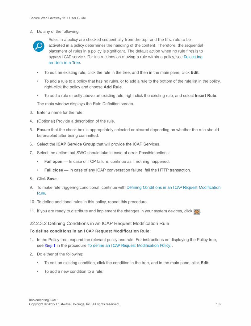
Secure Web Gateway 11.7 User Guide
2. Do any of the following:
• To edit an existing rule, click the rule in the tree, and then in the main pane, click Edit.
• To add a rule to a policy that has no rules, or to add a rule to the bottom of the rule list in the policy, right-click the policy and choose Add Rule.
• To add a rule directly above an existing rule, right-click the existing rule, and select Insert Rule.
The main window displays the Rule Definition screen.
3. Enter a name for the rule.
4. (Optional) Provide a description of the rule.
5. Ensure that the check box is appropriately selected or cleared depending on whether the rule should be enabled after being committed.
6. Select the ICAP Service Group that will provide the ICAP Services.
7. Select the action that SWG should take in case of error. Possible actions:
• Fail open — In case of TCP failure, continue as if nothing happened.
• Fail close — In case of any ICAP conversation failure, fail the HTTP transaction.
8. Click Save.
9. To make rule triggering conditional, continue with Defining Conditions in an ICAP Request Modification Rule.
10. To define additional rules in this policy, repeat this procedure.
11. If you are ready to distribute and implement the changes in your system devices, click .
22.2.3.2 Defining Conditions in an ICAP Request Modification RuleTo define conditions in an ICAP Request Modification Rule:
1. In the Policy tree, expand the relevant policy and rule. For instructions on displaying the Policy tree, see Step 1 in the procedure To define an ICAP Request Modification Policy:.
2. Do either of the following:
• To edit an existing condition, click the condition in the tree, and in the main pane, click Edit.
• To add a new condition to a rule:
Rules in a policy are checked sequentially from the top, and the first rule to be activated in a policy determines the handling of the content. Therefore, the sequential placement of rules in a policy is significant. The default action when no rule fires is to bypass ICAP service. For instructions on moving a rule within a policy, see Relocating an Item in a Tree.
Implementing ICAPCopyright © 2015 Trustwave Holdings, Inc. All rights reserved. 152

Secure Web Gateway 11.7 User Guide
a. Right-click the rule and choose Add Condition.
The main window displays the Condition Definition screen.
b. In the Condition Name field, select the type of condition in the drop down list.
For any selected condition type, the window displays an appropriate check box list.
For detailed information on condition types and the particular items in a condition list, see the SWG
Management Console Reference Guide.
3. If the condition has any other special fields or requirements, fill them in appropriately.
4. Click Save.
5. If you are ready to distribute and implement the changes in your system devices, click .
Implementing ICAP153 Copyright © 2015 Trustwave Holdings, Inc. All rights reserved.

Secure Web Gateway 11.7 User Guide
Implementing ICAPCopyright © 2015 Trustwave Holdings, Inc. All rights reserved. 154

About Trustwave®
Trustwave is a leading provider of compliance, Web, application, network and data security solutions delivered through the cloud, managed security services, software and appliances. For organizations faced with today's challenging data security and compliance environment, Trustwave provides a unique
approach with comprehensive solutions that include its TrustKeeper® portal and other proprietary security solutions. Trustwave has helped hundreds of thousands of organizations — ranging from Fortune 500 businesses and large financial institutions to small and medium-sized retailers — manage compliance and secure their network infrastructures, data communications and critical information assets. Trustwave is headquartered in Chicago with offices worldwide.
For more information, visit https://www.trustwave.com.