swimming pool pump · to your clarke dealer immediately. description this centrifugal swimming pool...
TRANSCRIPT

OPERATING & MAINTENANCEINSTRUCTIONS
GC0414
SWIMMING POOL PUMPModel SPPT1
Part No: 7175040
2
Parts & Service: 020 8988 7400/E-mail:[email protected] or [email protected]
INTRODUCTION
Thank you for purchasing this CLARKE pump.
Before attempting to operate the pump, it is essential that you read thismanual thoroughly and carefully follow all instructions given. In doing so youwill ensure the safety of yourself and that of others around you, and you canalso look forward to the pump giving you long and satisfactory service.
Upon receipt of the product, any damage or deficiency should be reportedto your CLARKE dealer immediately.
DESCRIPTIONThis centrifugal swimming pool pump is designed for the filtration of small tomedium size swimming pools and for pumping clean water only andoperating with contaminated or salt water should be avoided.
When used with permanently installed pools, the pump should be fixed in ahorizontal position and the use of a non-return valve will facilitate immediatepriming. The pump inlet is higher than the impeller inlet so that it can startoperating when only the pump body is filled with water.
The SPPT1 incorporates an integral timer which can be set to operate for apre-determined time between 2 and 24 hrs. The timer has a back up batteryto save the settings in case of loss of electrical power, allowing the pump tostart again once power is restored.
GUARANTEEThis CLARKE product is guaranteed against faulty manufacture for a period of12 months from the date of purchase. Please keep your receipt as proof ofpurchase.
This guarantee is invalid if the product is found to have been abused ortampered with in any way, or not used for its intended purpose.
Faulty goods should be returned to their place of purchase, no product canbe returned to us without prior permission.
This guarantee does not effect your statutory rights.
3
Parts & Service: 020 8988 7400/E-mail:[email protected] or [email protected]
GENERAL SAFETY PRECAUTIONS
WARNING: This swimming pool pump is not a submersible pump. Onno account should it ever be immersed in water.
WARNING: Always connect the pump to an earthed power supply viaan RCD.
1. ALWAYS keep the pump room clean and well lit. Floors should always bekept clear. Cluttered or dark areas invite accidents.
2. NEVER over-reach. Keep your proper footing and balance at all timeswhen installing or maintaining the pump.
3. NEVER direct any water discharge towards electrical wiring or equipment.
4. ALWAYS thoroughly familiarise yourself with this pump & its operation, andfollow all instructions in this manual. Never allow persons unfamiliar withthese instructions to operate the pump.
5. ALWAYS ensure that the pump is properly installed to prevent it frommoving during operation, and that the immediate area surrounding thepump is kept clear.
6. ALWAYS maintain the pump with care and keep it clean for best / safestperformance.
7. NEVER use this product if any part is damaged. Have it inspected andrepaired by your local Clarke dealer. Always turn the pump off beforecarrying out any maintenance.
8. NEVER modify this pump in any way. Use it ONLY for the purpose for whichit is designed.
9. NEVER use for pumping flammable liquids or corrosive chemicals. Thispump is designed to pump clean water only.
10. NEVER switch the pump ON when the pool is in use. ALWAYS disconnectthe pump from the electrical supply when the pool is in use.
11. ALWAYS have the pump serviced by your local CLARKE dealer, using onlyidentical replacement parts. This will ensure the safety of the pump ismaintained. The use of non standard parts could be hazardous.
12. NEVER allow the pump to run dry.
Your CLARKE water pump has been designed to give long and trouble freeservice. If, however, having followed the instructions in this booklet carefully,you encounter problems, take the unit to your local CLARKE dealer.
Please keep these instructions in a safe place for future reference.
4
Parts & Service: 020 8988 7400/E-mail:[email protected] or [email protected]
ELECTRICAL CONNECTIONS
WARNING! Read these electrical safety instructions thoroughlybefore connecting the product to the mains supply.
Before switching the product on, make sure that the voltage of yourelectricity supply is the same as that indicated on the rating plate. Thisproduct is designed to operate on 230VAC 50Hz. Connecting it to any otherpower source may cause damage.
This product may be fitted with a non-rewireable plug. If it is necessary tochange the fuse in the plug, the fuse cover must be refitted. If the fuse coverbecomes lost or damaged, the plug must not be used until a suitablereplacement is obtained.
If the plug has to be changed because it is not suitable for your socket, ordue to damage, it should be cut off and a replacement fitted, following thewiring instructions shown below. The old plug must be disposed of safely, asinsertion into a mains socket could cause an electrical hazard.
WARNING! The wires in the power cable of this product arecoloured in accordance with the following code:
Blue = Neutral Brown = Live Yellow & Green = Earth
If the colours of the wires in the power cable of this product do notcorrespond with the terminal markings of your plug, proceed as follows:
• The wire which is coloured Blue must be connected to the terminalwhich is marked N or coloured Black.
• The wire which is coloured Brown must be connected to theterminal which is marked L or coloured Red.
• The wire which is coloured Yellow & Green must be connected tothe terminal which is marked E or or coloured Green.
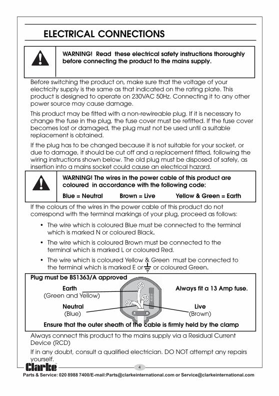
Plug must be BS1363/A approved
Earth Always fit a 13 Amp fuse.(Green and Yellow)
Neutral Live (Blue) (Brown)
Ensure that the outer sheath of the cable is firmly held by the clamp
Always connect this product to the mains supply via a Residual CurrentDevice (RCD)
If in any doubt, consult a qualified electrician. DO NOT attempt any repairsyourself.

5
Parts & Service: 020 8988 7400/E-mail:[email protected] or [email protected]
INSTALLATION
Because of the variety of possible installations, no plumbing accessories aresupplied with your pump, however accessories are available from yournearest CLARKE dealer. Contact your CLARKE dealer for further information,or CLARKE International Sales Department on 01992 565333.
Note: It is recommended that the end user should consult a qualified installerif there are any doubts as to the suitability of this product for a particularinstallation.
IMPORTANT: The pump MUST NOT be connected to the mains power supplyuntil all hose/pipe installation is completed.
INSTALLATION OF THE PUMP
A typical installation of a swimming pool pump is shown in Fig 1. The pumpmust always be installed and operated in a horizontal position i.e. with theoutlet port facing vertically upwards. The fixing holes in the base should beused to secure the pump firmly in it’s operating position. Mount the pump onraised blocks or a purpose built platform to protect it from flooding. Somekind of anti-vibration mounting is also desirable.
Always ensure there is adequate air circulation around the motor. The pumpshould be installed in a dry, well ventilated enclosure, sheltered from rain,such as a purpose built pump room.
The pump is usually installed between the pool skimmer and the pool filterand should be positioned as near to the pool water level as possible. In otherapplications, a suction strainer should be used to protect the pump fromingress of foreign matter.
Fig 1
Pool
Skimmeroutlet
Pool FilterPool Side
Remote PowerConnection

6
Parts & Service: 020 8988 7400/E-mail:[email protected] or [email protected]
ELECTRICAL CONNECTIONThe pump should be located at a safe distance, (usually 2 metres), awayfrom the pool, and the power supply should be at least 3.5 metres from thepool. If in doubt, please contact your electrical specialist and refer to theInternational Electrical Commission (IEC) standard, (Electrical Installations forBuildings-part 7), referring to ‘swimming pools and other basins’.
Avoid situations where the pump could become drenched with water asneither the motor or terminal box are designed to be waterproof. Ensure thepump & its cable do not create a safety hazard for people walking past it.
PIPE/HOSE CONNECTIONSThe pump inlet will be connected to any pool skimmer and/or pool drainconnection, depending upon the installation layout, and the dischargeoutlet should be connected to your water filter.
The diameter of the inlet/outlet connectors is 40 mm. Therefore hoses with thesame nominal diameter should be used and secured with a worm drive clip.Ensure all connections are air tight. Tighten them enough to secure the hoseduring pressurised operation, but not so tight as to crack the plastic inlet/outlet connectors.
Where the pump is to be a permanent fixture, vibration and strain onadjacent parts can be reduced by the insertion of a short flexible section ofhose between any rigid pipework and the immediate area of the pump.
Any air leaks in the suction line will inhibit priming and reduce the capacity ofthe pump. Ensure there are no kinks in any flexible hose used.
The performance of your pump will be affected by the diameter of the inletpipe - any restriction will greatly reduce the flow. We recommend that youalways use a pipe diameter at least equal to, or greater than the diameter ofthe pump connections.
To prevent unnecessary strain or possible distortion to the pump, ensure thatadequate support is provided to the hoses and or pipes. They will beconsiderably heavier when filled with water.
It is suggested that suction and delivery isolation valves are fitted in order toisolate the pump. A gate valve may be installed in-line on the delivery side(outlet port) of the pump which can be adjusted as required to regulate theflow of water and can assist in priming the pump.
Protect the pump and pipework from freezing with the addition of suitablelagging. The formation of ice may cause serious damage.

7
Parts & Service: 020 8988 7400/E-mail:[email protected] or [email protected]
SUCTION LIFT OR GRAVITY FEEDThe schematic diagrams, figs. 2 and 3, illustrate possible methods of pipeworkinstallation. This pump is designed primarily to be gravity fed, that is, drawingwater from an above ground pool. However, it is possible to draw water froma sunken pool, providing the suction lift does not exceed the distancespecified for your pump. The suction lift i.e. the vertical distance between thewater level and the pump should not exceed 7 metres.
A foot valve/filter must be fitted to the lowerend of the suction hose, (as illustrated in fig2), so as to help retain water in the suctionsystem. Remember.... this is NOT a self primingpump.
When suction lift is used to draw water intothe pump it is essential that all connectionsand hoses are completely air tight, otherwisethe system will not work.
Before pumping it is essential to completely fillthe suction side with water. This is known aspriming the pump and is carried out asfollows:-
1. With the pump, all inlet pipes/hoses and the foot valve in position, slowlypour water into the outlet port. Wait until all air is expelled...this may take aminute or two...and fill to the brim before connecting the outlet hose tothe outlet port. The hose is then connected to the water filter.
2. Switch on the pump. Water should start to flow through the system. Checkfor leaks and repair as necessary.
Do not allow the pump to run dry, otherwise the seal between the pump andmotor may be damaged. If a leak is noticed at this point it may indicate thatthe seal is worn and therefore in need of replacement. Contact your CLARKEdealer, or the Clarke International Service Department for advice.
Do not place any restriction on the inletside of the pump.
Remember - this pump is designed forpumping CLEAN WATER with small solidsin suspension, ONLY. DO NOT USE forpumping chemicals or other corrosiveliquids (other than pool purificationchemicals in their correct mix ratio).
Fig 2:-Suction Lift
FIG 3:- Gravity Feed
8
Parts & Service: 020 8988 7400/E-mail:[email protected] or [email protected]
OPERATION1. Open any valves in the pipeline.
2. If operating the pump for the first time, disconnect the top hose and primethe pump by filling completely with water.
Note: The pump is only self- priming when filled with water. Refilling is onlynecessary if the pump has been drained, or if all the water has been lost.
3. Connect to the power supply and switch on. Water should start to flowthrough the system. Check for any leaks and repair as necessary.
4. If the motor fails to start, or the pump does not deliver water, refer toTROUBLESHOOTING on page 9. Never operate the pump when not filledwith water or if the inlet is blocked.
Note: Filling the suction pipe with water will speed up the priming process,and it is suggested that a non-return valve be fitted to the end of thesuction pipe.
5. Stop the pump by switching off the power supply.
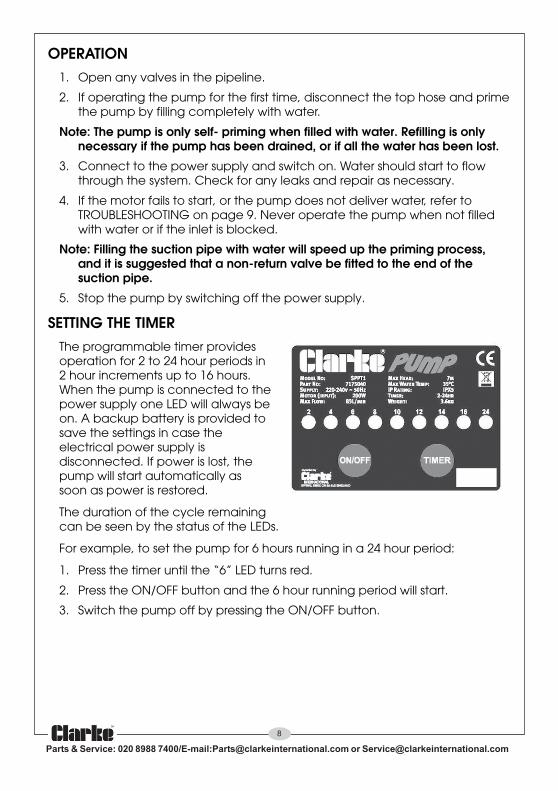
SETTING THE TIMERThe programmable timer providesoperation for 2 to 24 hour periods in2 hour increments up to 16 hours.When the pump is connected to thepower supply one LED will always beon. A backup battery is provided tosave the settings in case theelectrical power supply isdisconnected. If power is lost, thepump will start automatically assoon as power is restored.
The duration of the cycle remainingcan be seen by the status of the LEDs.
For example, to set the pump for 6 hours running in a 24 hour period:
1. Press the timer until the “6” LED turns red.
2. Press the ON/OFF button and the 6 hour running period will start.
3. Switch the pump off by pressing the ON/OFF button.
9
Parts & Service: 020 8988 7400/E-mail:[email protected] or [email protected]
CARE DURING USE1. Do not allow the pump to run dry, otherwise the seal between the pump
and motor may be damaged. If a leak is noticed at this point, it mayindicate that the seal is worn and therefore in need of replacement.Contact your CLARKE dealer, or the Clarke International ServiceDepartment for advice.
2. In the event of a blockage, where debris has entered the suctionchamber, it can be cleaned out as described under MAINTENANCE.
3. Should contaminants come into contact with the pump, flush through withcold water as soon as possible to prevent damage to the pump. DO NOTUSE for pumping chemicals or other corrosive liquids (other than poolpurification chemicals in their correct mix ratio).
4. If the pump is being used to drain the pool, ensure there is adequatedrainage and there is no risk of damage to property as a result of waterbeing discharged. If a flexible hose must be laid across a roadway,protect it with wooden planking.
MAINTENANCEThe only maintenance required is a regular inspection to ensure that debris isnot blocking the passage of water through the pump.
If you suspect the pump is blocked by silt, leaf debris etc, disconnect it fromthe mains supply and back-flush to clear any blockage using a hose. You willneed to disconnect the outlet hose to do this.
Always keep the pump in a clean condition, checking regularly for loose boltsor a damaged power cable etc.
The pump should not be taken apart by the user in the case of overhaulbeing required, but should be taken to your nearest Clarke dealer forspecialist repair.
AFTER USEAfter use, and if the pump will not be used over the winter period, orwhenever there is danger of freezing, always drain the pump body. If thepump has been used with contaminated or salty water, it should bethoroughly flushed with clean water following use, both inside and out. Itshould then be drained and covered over, if not already installed in a clean,dry environment sheltered from the weather.
Remember to re-prime the pump when returning to service.
In the event that dismantling and overhaul of the pump is necessary, contactyour CLARKE International Service Department on 020-8988-7400.

10
Parts & Service: 020 8988 7400/E-mail:[email protected] or [email protected]
THE TIMER BATTERYThe timer is equiped with a re-chargable battery which should re-chargewhen the pump is running. Tamper-proof screws are used to secure the topcover requiring a Y-type screwdriver. If one is not available and the batteryhas failed, take the pump to your Clarke dealer.
ENVIRONMENTAL PROTECTIONAny redundant accessories and packaging should be sorted and takento a recycling centre to be disposed of appropriately.
Through the purchase of this product, the customer is taking on theobligation to deal with the WEEE in accordance with the WEEE regulations inrelation to the treatment, recycling & recovery and environmentally sounddisposal of the WEEE.
In effect, this means that this product must not be disposed of with generalhousehold waste. It must be disposed of according to the laws governingWaste Electrical and Electronic Equipment (WEEE) at a recognised disposalfacility.
TECHNICAL DATADimensions (L x W x H): 307 x 142 x 220 mm
Weight: 3.6 kg (8 Lb)
Inlet/Outlet Size: 40 mm
Max Flow: 83 L/min
Max Head: 7 m
Max Water Temperature: 35ºC
Suitable Water Type: Swimming pools/clean water
Power Supply: 220-240V @50 Hz
Sound Pressure Level: 68.6 dB LpA
Sound Power Level: 69.3 dB LwA
Guaranteed Sound Power: 73 dB LwA
Timer Run Times: 2 hour increments - 24 hours
Power Cable Length: 1.8 m
Please note that the details and specifications contained herein, are correct at thetime of going to print. However, CLARKE International reserve the right to changespecifications at any time without prior notice.

11
Parts & Service: 020 8988 7400/E-mail:[email protected] or [email protected]
TROUBLESHOOTING
MELBORP ESUAC NOITULOS
tonseodpmuP.nur
ylppussniamoN dnaylppusrewopdesufkcehCkcehc(yrassecenfiesufecalper
tiucrickcehC.)gnitaresuf.rekaerb
.dekcolb/deziesrellepmI sniammorfpmuptcennocsiDdnaesuacetagitsevnI.ylppus
.egakcolbraelc
otsliafpmuP.emirp
noitcushguorhtskaelriAdegamad(stniojesoh,pmalcnekorb,esoh
)teksaggnittif-lli/degamad
esohecalper/snoitcennocriapeR.yrassecensa
.esohtelnidekcolB remmiksloopdnaenilepipkcehCtelniynakcehC.egakcolbrof
.nepoyllufsidettifevlav
tubsnurpmuProopsevig
.tuptuo
edisnilairetamdetsegnoC.pmup
.pmuphsulfkcab&tuonaelC
enilyreviledronoitcuS.detcurtsbo
erusnednanoitcurtsboevomeR.enilyrevilednisknikoneraereht
.egakaelepiptelnI rotcennocdnaepiptelnikcehC.deriuqersanethgiT.skaelrof
hguorhtskaelriA.laesdegamad
.laesweneR
dnadegamadrellepmI.laesroopgnikam
rofrelaedEKRALCruoyotnruteR.riaper
laeslacinahcem/rellepmI.nrowyldabsi
rofrelaedEKRALCruoyotnruteR.riaper
ehtnisessolnoitcirfhgiH.enilnoitcus
,sevrucyrassecennudiovA.sevlavrosnoitcirtser
gnitluserdetisyldabpmuP.hgihoottfilnoitcusni
otelbissopsaesolcsapmupteSebotretawehtfoleveleht
.depmup
fossolnedduS.wolf
.epiptelnifoegakcolB remmiksloopdnaenilepipkcehC.egakcolbrof
12
Parts & Service: 020 8988 7400/E-mail:[email protected] or [email protected]
TROUBLESHOOTING
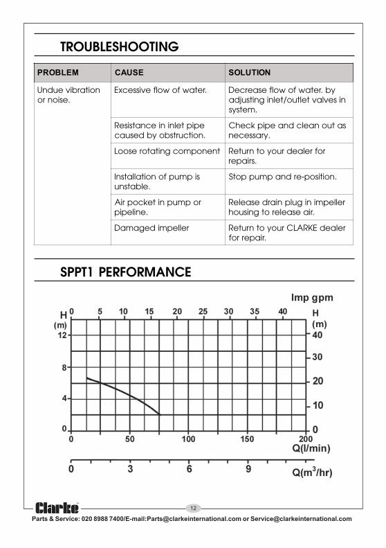
SPPT1 PERFORMANCE
MELBORP ESUAC NOITULOS
noitarbiveudnU.esionro
.retawfowolfevissecxE yb.retawfowolfesaerceDnisevlavteltuo/telnignitsujda
.metsys
epiptelniniecnatsiseRybdesuac .noitcurtsbo
satuonaelcdnaepipkcehC.yrassecen
tnenopmocgnitatoresooL rofrelaedruoyotnruteR.sriaper
sipmupfonoitallatsnI.elbatsnu
.noitisop-erdnapmuppotS
ropmupnitekcopriA.enilepip
rellepminigulpniardesaeleR.riaesaelerotgnisuoh
rellepmidegamaD relaedEKRALCruoyotnruteR.riaperrof
13
Parts & Service: 020 8988 7400/E-mail:[email protected] or [email protected]
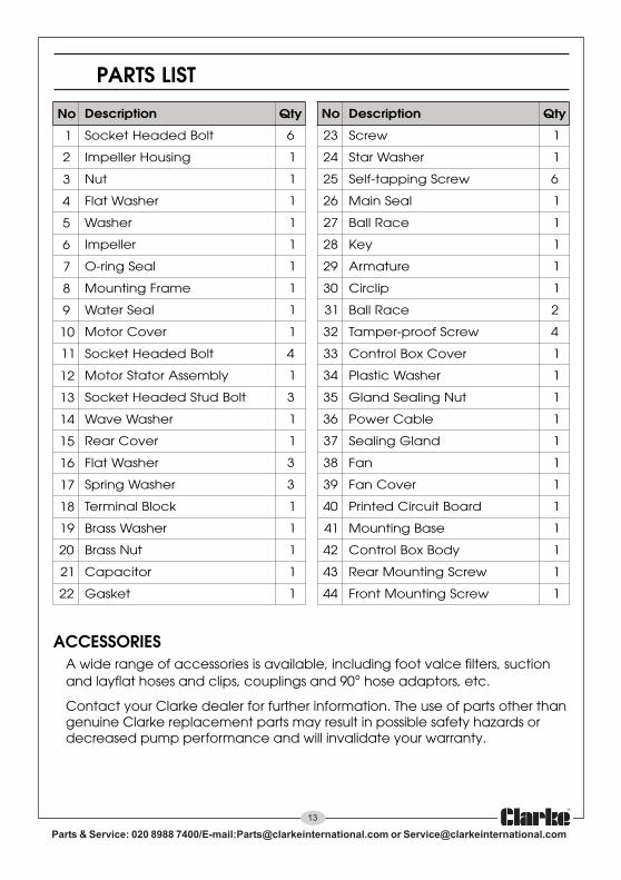
PARTS LIST
oN noitpircseD ytQ oN noitpircseD ytQ
1 tloBdedaeHtekcoS 6 32 wercS 1
2 gnisuoHrellepmI 1 42 rehsaWratS 1
3 tuN 1 52 wercSgnippat-fleS 6
4 rehsaWtalF 1 62 laeSniaM 1
5 rehsaW 1 72 ecaRllaB 1
6 rellepmI 1 82 yeK 1
7 laeSgnir-O 1 92 erutamrA 1
8 emarFgnitnuoM 1 03 pilcriC 1
9 laeSretaW 1 13 ecaRllaB 2
01 revoCrotoM 1 23 wercSfoorp-repmaT 4
11 tloBdedaeHtekcoS 4 33 revoCxoBlortnoC 1
21 ylbmessArotatSrotoM 1 43 rehsaWcitsalP 1
31 tloBdutSdedaeHtekcoS 3 53 tuNgnilaeSdnalG 1
41 rehsaWevaW 1 63 elbaCrewoP 1
51 revoCraeR 1 73 dnalGgnilaeS 1
61 rehsaWtalF 3 83 naF 1
71 rehsaWgnirpS 3 93 revoCnaF 1
81 kcolBlanimreT 1 04 draoBtiucriCdetnirP 1
91 rehsaWssarB 1 14 esaBgnitnuoM 1
02 tuNssarB 1 24 ydoBxoBlortnoC 1
12 roticapaC 1 34 wercSgnitnuoMraeR 1
22 teksaG 1 44 wercSgnitnuoMtnorF 1
ACCESSORIESA wide range of accessories is available, including foot valce filters, suctionand layflat hoses and clips, couplings and 90° hose adaptors, etc.
Contact your Clarke dealer for further information. The use of parts other thangenuine Clarke replacement parts may result in possible safety hazards ordecreased pump performance and will invalidate your warranty.

14
Parts & Service: 020 8988 7400/E-mail:[email protected] or [email protected]
PARTS DIAGRAM
SPARE PARTSWhen requesting spare/replacement parts for these pumps from CLARKEParts & Service, please quote the prefix ‘ZG’ followed by the model number(SPPT1) and the item number from the parts list/diagram.

15
Parts & Service: 020 8988 7400/E-mail:[email protected] or [email protected]
DECLARATION OF CONFORMITY