swimming pools design 2011
DESCRIPTION
Swimming Pools Design 2011TRANSCRIPT

February Revision 003 © Sport England 2011
DesignGuidance Note
Updated & Combined guidance
DRAFT FOR DISCUSSION
Creating sporting opportunities in every community
Swimming Pools
Updated Guidance for 2011

Swimming Pools DesignGuidance Note
February Revision 003 1 © Sport England 2011
Foreword
Sport England believes that good facilities are fundamental to developing sporting opportunities for everyone, from the youngest beginner to the international class athlete. The buildings, whether large or small, can encourage civic pride and assist the process of revitalising deprived neighbourhoods. Facilities that are well designed, built to last and well maintained are a pleasure to use and give an ample return on the time and money invested in their construction and day to day use.
Good design needs to be based on a sound understanding of issues such as the current trends and practices within individual sports, developments in the sport and leisure industry and the lessons to be learnt from previously built schemes.
Good design needs to be embraced within the earliest vision statement for a particular project and enshrined in the initial briefing stage through to the final detailed specifications and operational arrangements.
Sport England Design Guidance notes aim to promote a greater general understanding of overall design concepts, an appreciation of technical issues as well as the critical factors that need to be considered in reaching the appropriate solution for a particular project. They also advise where further information, advice and expertise may be found and point to benchmark examples.
A well designed pool can attract swimmers
Increase awareness of good design in sports facilities.
Help key building professions, clients, user representatives and other stakeholders to follow best practice.
Encourage well designed sports facilities that meet the needs of sports and are a pleasure to use.
•
•
•
Sport England’s Design Guidance Notes aim to:

Swimming Pools DesignGuidance Note
February Revision 003 2 © Sport England 2011
Contents1.0 Introduction 3
National statistics•Trends•Condition and public expectation•Partnership and cooperation•
2.0 Early considerations 5
Financial sustainability•Strategic issues•Size and shape of water•Level of competition•Pool capacity•Leisure features•
3.0 Site 12
Location and site evaluation•Site planning•External design•
4.0 Organising the building 16
4.1 Relationship of spaces 16
4.2 First impressions 19Entrance area•Reception desk•Refreshment areas•Public toilets•Accommodation for children•
4.3 Pool hall 23Structural approach•Glazing•Artificial lighting•Signs•
4.4 Pool tank(s) 26Configuration•Main pool•Combining two pools in one hall•Learner and training pools•Diving pools•Easy access to the water•Privacy for some user groups•Movable floors and bulkheads•
4.5 Changing facilities 41Key design issues•General planning principles•Changing layouts•Analysis of types of changing rooms•Calculating numbers•Benches, coat hooks and lockers•Toilets•Showers•Vanity areas•
4.6 Ancillary accommodation 49Office accommodation•Staff rooms and changing•Cleaners store•External service yard•First aid room•Pool equipment store•
4.7 Typical fixtures and fittings 52
4.8 Spectator & competitor provision 55
5.0 Servicing the building 57
Energy implications•Energy efficiency•Renewable energy•Water efficiency•Pool water quality•Disinfection •Chemical dosing•Water softness•Filtration systems•Turnover rates•Water temperature•Air temperature and humidity•Electrical installations•Size of plant room•Plant room spaces•Air distribution systems•
6.0 Constructing the building 65
Types of pool tank design and surround•Pool edge details•Finishes to wet areas•Structural frame•Roof enclosure•External walls•Glazing•Internal walls•Movable floors and bulkheads•Fixed pool equipment•Stainless steel in the pool hall environment•Doors and frames•Acoustics•
7.0 Operating the building 79
Key operational / design issues•Key maintenance issues•
8.0 Appendices 81
Related organisations 811. Standards and legislation 822. Changing room calculations example 853. Improvement and alterations to existing 4. swimming pools 87Further information on leisure pools 935. Further information and references 6. 95

Swimming Pools DesignGuidance Note
February Revision 003 3 © Sport England 2011
1.0 Introduction
This guidance note outlines the basic principles and concepts of good swimming pool design. It is aimed at all those involved in developing swimming provision, points to further information and gives a number of best practice examples.
Swimming is second only to walking as the nation’s most popular physical activity with over 22% of adults and 50% of young people taking part on a regular basis 1. It can be enjoyed by people of both sexes and by all ages and abilities and is recognised as being uniquely beneficial to the nation’s health and well being. It is ideally suited for people with disabilities and the elderly or infirm who might have difficulties with other forms of exercise.
Swimming and water safety is an essential life skill. As part of the National Curriculum, it can encourage fitness and good health practices amongst young people. It is regarded as an essential part of children’s education of the safe enjoyment of most water activities and an understanding of the wider environment around them.
Swimming, like all other sports, can play a significant part in community regeneration and new or refurbished pools can provide much valued facilities that make an important contribution to community cohesion and general health and well being.
National statistics
It is estimated 2 that there are almost 1,400 swimming clubs and associations in England ranging from small clubs which concentrate on the teaching of swimming to the very large clubs involved in competition in swimming, diving, synchronised swimming, water polo, open water and disabled swimming. These voluntary organisations provide the foundations for competitions at all levels and the development of talent. Swimming pools also provide for a wide range of other activities from aqua-aerobics to sub-aqua training, and most commonly simple recreational and fitness swimming.
It is also estimated 3 that there are almost 4,614 separate swimming pools sites in England with a total water 872,910m2. Approximately 25% of this water area is provided by the education sector, 46% by local authorities (or trusts) and 26% by the commercial sector. The stock of pools is in various forms:
Indoor or outdoors•
Free form or rectangular•
Heated or unheated•
Associated with hotels, health clubs, water •parks, beaches and other private operations.
Trends
In recent years England has seen a growth of commercial pools to the point that in numerical terms they are now almost equal to the numbers of Local Authority pools. However the commercial pools tend to be small in size and with shallower water, being aimed primarily at the fitness / aerobic / recreation market. They tend to offer a reduced
1 Sport England Active People Survey.
2 ASA ‘From Arm Bands to Gold Medals’ 2001/2.3 State of the Nation Facility Report – Swimming Pools – November 2007.
Swimming can be enjoyed by people of both sexes across all ages and abilities and is recognised as being uniquely beneficial to the nation’s health and well being.

Swimming Pools DesignGuidance Note
February Revision 003 4 © Sport England 2011
programme of activities and have restrictive pricing. They are less likely to allow for competition swimming or teaching. The trend for the education sector is to be a diminishing provider of swimming facilities.
Condition and public expectation
It has been acknowledged by Government that public swimming facilities in England have generally suffered from under funding and need constant maintenance and repair, placing many under threat of closure 4.
Only a few of the Victorian municipal baths, once the pride of Britain’s big cities, remain. In addition, hundreds of council pools built in the 1960s and 1970s are close to the end of their economic life span. Local Authorities are often faced with the difficult decisions to close pools with strong local opposition. In some cases these are buildings of historical and architectural importance 5.
There are also considerable pressures on schools where the majority of pools were built in the 60’s and early 70’s, many to a poor standard. Schools face logistical problems, additional costs, health & safety issues and time and staff training issues in delivering the national curriculum. The Government’s ‘Building Schools for the Future programme’, to rebuild or refurbish all secondary schools over a 15 year period may result in many existing pools not being refurbished or replaced 6.
Best practice includes:
New community pools •that cater for school needs
Existing public and •commercial pools being shared between schools and the wider community.
4 DCMS Spending review 2004.
5 Great Lengths: The historic indoor swimming pools of Britain. English Heritage.6 Building Schools for the Future: Adding value with swimming. ASA.
7 Programmes of swimming activities are also drawn up within the National Curriculum for Key Stages 1, 3 and 4.
In contrast, the last decade saw a growing number of lottery funded swimming pools. Modern design, together with more attractive internal features and greater attention to customer’s needs has created a step change in pool provision. The Active Places database shows that since 1996 some 56% of the national stock has been built or benefited from some degree of refurbishment. However, the likelihood of significant lottery funding being available in the immediate future is doubtful.
Partnership and cooperation
Careful consideration needs to be given to the overall justification and briefing for swimming provision.
Schools, Local Education Authorities, health agencies and local government should seek to work with members of the wider community to capitalise on knowledge, experience and resources. They should seek to establish clear swimming strategies.
Existing pool provision in any particular area may need to be rationalised; schools with existing pools might share them with other schools and the wider community; pools being refurbished or replaced should consider the needs of the entire community.
The ‘Swimming Charter 2003’ published by Department of Children, Schools & Families (DCSF) and the Department of Culture, Media and Sport (DCMS) gives various case studies where swimming has been provided on a community basis to allow school swimming to move beyond the essential minimum requirement of Key Stage 2 of the National Curriculum 7.
There is also an impressive core of organisations concerned with development, management and safety issues. See Appendix 1.

Swimming Pools DesignGuidance Note
February Revision 003 5 © Sport England 2011
Good design can:
Maximise customer appeal•Allow flexibility for •maximum programme options
Provide efficient and well •organised circulation
Minimise staffing levels •whilst allowing the effective management of health and safety
Help achieve sustainability •and be responsive to environmental issues
Minimise cleaning and •maintenance requirements
Reduce the footprint and •volume
Help achieve financial •sustainability.
2.0 Early Considerations
Public swimming pools are unusually demanding buildings that require considerable investment to design, build and operate. Much of the plant must operate continuously 24 hours a day over 365 days a year under stringent health and safety requirements to ensure safe, supervised use. They have high energy needs in operation and must be carefully designed to conserve energy. They contain aggressive chemicals in moisture-laden atmospheres that require careful design and high quality materials, plant and equipment and well qualified staff.
The full environmental impact of such buildings through their life cycle should be carefully considered and it is recommended that the BREEAM assessment method be adopted 8.
Pools outside the public sector, though possibly less intensively used, must also achieve safe and acceptable operating conditions.
All new pools will need to be designed in line with the new European standard BSEN 15288-1:2008. See Appendix 2. Existing Health & Safety documentation will also need to be carefully considered in respect of both design and operation of a pool 9.
The Construction (Design and Management) Regulations 2007 (CDM 2007) which, in conjunction with the Heath and Safety at Work Act and BSEN 15288-1:2008, identifies the need to establish a strong project team. This team should include designers, client, operators and contractors with sound experience and expertise with similar projects in both scale and type from the outset of any project. Refer also to the Sport England / CABE document ‘Better Places for Sport’ available from the Sport England website.
8 The Building Research Establishment Environmental Assessment Method (BREEAM) includes leisure buildings. http://www.breeam.org/page.jsp?id=14 9 Health & Safety Executive’s (HSE) document HSG179Managing Health & Safety in Swimming Pools’ , PAS 39,PAS 65 and PWTAG Guide.

Swimming Pools DesignGuidance Note
February Revision 003 6 © Sport England 2011
Establish a strong project team including client, designers, operator and contractors with sound experience and expertise from the outset.
Financial sustainability
Even the best designed public pools are likely to be run on a subsidised basis and it is important to consider the long term financial sustainability from the outset. The initial capital costs and the ongoing operational costs should be balanced with the benefits that will be offered.
There are strong arguments for swimming pools to be combined with other facilities such as health and fitness facilities. This way they produce an income stream without incurring excessive additional running costs in order to offset subsidies and to achieve economies of scale. It is essential that realistic business planning runs in tandem with the planning and design processes.
Leisure features
A number of pools include some leisure water area that includes features designed to increase appeal and attract custom. There are ranges of possible options that may include:
Varying water depths, with extensive shallow •or beach areas
Wave pools and surfing pools•
Water slides & flumes•
Fast flowing river rides & rapids•
Water jets & water cannons•
Water features e.g. rain showers•
Spa facilities, including varying temperatures•
Children’s wet play equipment•
Feature lighting and sound – to introduce a •more theatrical environment
Theming to increase excitement and appeal.•
Larger scale leisure centres are usually planned as ‘destination’ facilities that attract people from a wide catchment for a ‘day out’ experience.
Leisure features are outside the scope of this guidance note, but further information is included in Appendix 5.
Strategic Issues
The following strategic questions need to be considered:
The fit with the local authority’s leisure/•recreation strategy and sports development initiatives?
Sporting objectives: for example the impact •on local community participation or the significance on a wider catchment of specialist training and competition features?
Cost pyramid: Value for money is essential - Invest in good design and specification to reduce whole life costs (staff, maintenance, repair and running cost)-Ensure adequate maintenance budgets are available.
Design team fees
Construction costs
Heating, lightingcleaning andmaintenance
Staff
Capital costs
Revenue costs

Swimming Pools DesignGuidance Note
February Revision 003 7 © Sport England 2011
The user profile of the catchment area: who •will use it and when?
Whether the need can be met elsewhere or by •other means, for example by upgrading or extending an existing pool?
The impact on existing facilities• 10?
It is crucial that client groups liaise with their •local authority, their regional Sport England office, and advisory bodies such as the Amateur Swimming Association (ASA) to determine:
Whether there is a local strategy for O
swimming pool provision that covers the area?
What is the best size and type of facility O
recommended for their particular location?
On the Sport England website there is a section aimed at those involved in the development of sport in their local community and sustainable community strategy. This is a new tool that replaces the 1999 Sport England publication ‘Planning Across Boundaries’.
A swimming development strategy is essential to set out the context of sporting and management objectives for any new provision.
Ensure that balanced decisions are made about need and financial resources.
Key questions
Who will be the principal users? •
What activities need to be accommodated?•
Type, size and depth of pool(s) required?•
Number of people who will use the pool at any •one time?
Will the pool be used for competitive •swimming? – (What activities and to what standard?)
Is spectator viewing required and what level •can be justified?
Pool users will comprise a combination of the following groups:
Local community including ethnic / cultural •groups
Schools•
Swimming clubs•
People with disabilities•
Older people•
Carers with babies and young children. •
The main types of activity are likely to be:
Recreational swimming •
Learning to swim, including water- •acclimatisation for young children
Fitness swimming: e.g. lane swimming and •aqua aerobics
Training•
Competitive swimming.•
Other activities may include:
Diving •
Water polo•
Synchronised swimming•
Canoe practice•
Life saving practice•
Sub-aqua training•
Underwater hockey•
Leisure activities•
Private parties.•
Nearly all of these activities can be accommodated in a standard 25m (or 20m11) community pool with depths ranging from 0.9m–1.8m, by simply dividing the area with floating lane markers. For example, teaching swimming and shallow dives, recreational and fitness swimming, aqua aerobics, life saving practice and sub-aqua training.
10 The Sport England Active People website has segmentation data available from late 2007. 11 More suitable for school sites or remote rural locations.

Swimming Pools DesignGuidance Note
February Revision 003 8 © Sport England 2011
It should be recognised that new, replacement or refurbished pools, which meet present day standards, have the effect of increasing use. If the proposed pool water
area is too small it will be under constant pressure during busy periods.
Conversely pools that are oversized may be under used, less cost-effective and likely to result in greater financial deficit.S
Wet Change
Plant room
RZAST
PT
FA
SwimmingPool
Refreshment and viewing area
LearnerPool
Key:AST: Attendant staff accommodationFA: First AidPT: Public toiletsR: ReceptionRZ: Refreshement Zone e.g. vending, kitchenS: Store
R
Diagrammatic layout of a 4-lane 25m community pool with minimum circulation and good visibility of all key features incorporating viewing area.
Size and shape of water
Many small pools will be used solely for recreational and fitness swimming and will not necessarily need to strictly follow the ASA recommendations. However, it is generally recommended that standard dimensions should be used to allow appropriate levels of competition and training and to help meet safety standards. On the other hand relatively few pools need be designed to full competition standards and include spectator facilities 12.
Single community pools should have a minimum shallow water depth of 0.9m (if there is no learner pool) and a deep end of 1.8m or 2.0m. Where a learner pool is provided the shallow water depth of the main pool should be increased to 1.0m in order to better cope with tumble turns.
12 Further advice on spectator seating is given on page 55. 13 Also referred to as booms.
Training for competition, low level synchronised swimming, and water polo can all take place in a 25m pool and with modest spectator seating the pool will also be able to accommodate competitive events in these activities.
Diving from boards, advanced synchronised swimming and more advanced sub-aqua training require deeper water. These can all be accommodated in one pool tank, which ideally should be in addition to the main swimming pool. A dedicated tank for deep-water use may be an essential requirement for some activities at certain levels of competition.
The provision of separate water areas for different activities is, however, unlikely to be a cost-effective solution and difficult to justify, except where competition is a specific requirement. A more economical approach is to include a movable floor(s) and bulkhead(s) 13 to divide a single pool tank and create separate pool water areas of different depths. This allows greater use and programming flexibility. There are many ways such features can be configured and these are discussed in more detail from page 39.
Early advice should be sought from a range of manufacturers/suppliers on the overall design implications of integrating their plant / equipment into a design and a cost comparison carried out to determine the most appropriate option.

Swimming Pools DesignGuidance Note
February Revision 003 9 © Sport England 2011
Levels of competition
A new pool should be designed to meet the various needs of all the community it serves and in most instances designing for community use will allow the pool to be used by one or more of the 1,400 clubs which are a member of the Amateur Swimming Association (ASA). Where the pool is to be used for higher levels of competition it may be necessary to consider the specific needs of the ASA and for major competitions the requirements of the Federation Internationale de Natation Amateur (FINA)14. However these requirements do not prevent use by the general community.
Building elements affected include:
Dimensions and tolerances of the pool tank(s) •and pool surrounds
Sectional profile and water depths•
Provision of ancillary water areas – e.g. learner •pool that can double as a swim down pool
Poolside equipment including timing and •score board
Diving facilities•
Spectator seating•
Support accommodation•
Standards of illumination and water •treatment.
Consultation should occur early in the design process with the ASA and FINA as appropriate. FINA facility rules are available from their website.
ASA National Hierarchy 15
The ASA National Hierarchy identifies where a swimming facility may sit in respect of national swimming development as follows:
Swimming
50m major competition pools •
50m (or 25m) national/regional competition •pools
50m (or 25m) national intensive training •centres *
25m 8-lane county competition pools•
25m 6 lane community pools•
20m 4 lane small community or school pool•
Teaching/learner pools.•
Diving
High performance centres *•
World-class training centres *•
County and sub regional development centres.*•
Water Polo
International* sized playing areas•
County and sub regional development centres •25 x 12.5m deep water.
Synchronised swimming
International competition pools•
County and sub regional development centres •minimum 2.5 m depth.
* It should be noted that terms such as high performance, world class, international, national and regional, often refer more to the coaches and standard of athletes in development programmes run in particular facilities.
14 International Amateur Swimming Federation.15 Source: ‘From Armbands to Gold Medals’ - The National Facilities Strategy for Swimming.

Swimming Pools DesignGuidance Note
February Revision 003 10 © Sport England 2011
20m
8.5m
17m
8.5m
10.5
m13
m
25m
4 lane
8 lane
4 lane
5 lane
6 lane
10 - 20m
7m
25m 8 lanes
50m
side margin (or additional lane)
side margin (or additional lane)
50m Max competition pool + **
50m training pool - Width varies depending on need.
25m County Standard pool + **
25m recommended community swimming pool +**
25m 5 lane community swimming pool **
25m 4 lane community swimming pool **
20m 4 lane community pool **
7 x 10 - 20m learner pool **
Pool Type Length (m)
Width (m)
No of Lanes
Lane Width
Side Margin (m)
Depth (m)
Learner Pool ** 10 - 20 7 2 2.0 N/A 0.6 – 0.9
* Lengths given for competition include an allowance for timing pads.** Provision of a movable �oor allows the pool to be put to multi-purpose community use.+ Spectator & competitior seating provision should be discussed with the ASA/FINA appropriate to level of competition.
Minimum width of 10m - 4 lanes x 2.5m or 5 lanes x 2m. **
Community 20m ** 20 8.5 10.5
4 5
2.0 0.25 0.8 – 1.0
Community 25m ** 25 8.5 10.5 12.5
4 5 6
2.0 0.25 0.9 – 1.5 min 1.0 - 2.0 pref
Competition + 25.02* 13 6 2.0 0.5 1.0 - 1.80 min
Short Course Championship + 25.02* 17 8 2.0 0.5 1.80
Training Pool 50 10 - 17 4 - 8 2.0 0.5 1.0 - 1.80 min
ASA National Competition + 50.02* 19 21
8 2.25 § 2.5
0.5 1.0 - 1.80 min2.0 pref
FINA National Competition + 50.02* 21 8 2.5 0.2min 0.5pref
1.35min2.0 pref
§ Standard timing pad widths are 1.9m (2m lanes) or 2.4m (2.5m lanes). 2.25m wide lanes require bespoke timing panels.
50.02* 25 8 2.5 2.5 2.0 min FINA International Competition +
For water depths of 0.8m or less, changes in pool depths should be achieved with gradients of 1 in 20 (5%). For water depths between 0.8m and 1.35m, changes in pool depths should be achieved with gradients no steeper than 1 in 17 (6%). Where pool depths continue down to 1.5 or 1.8m the same gradient should preferably be continued. See diagram for tank pro�les, depths and gradients on page 32.
Table 1 Main pools - layouts and dimensions

Swimming Pools DesignGuidance Note
February Revision 003 11 © Sport England 2011
Pool capacity
The numbers of people likely to use the pool at any one time needs to be estimated early in the planning and design process. The figure can be used to assess the number of changing room places that are required and for more technical issues such as the design of the pool water filtration plant. It will therefore be a key factor in establishing the total floor area of the building.
Pool operators often refer to the maximum number of bathers estimated to be able to use a pool at any one time as the ‘bathing load’.
The pool capacity will vary according to the particular programme session/activity and will be a function of the available water area. It will also be dependent on water depth and configuration, and there being in place appropriate risk assessments and operational arrangements to ensure safety.
For un-programmed recreational swimming a minimum water area (occupancy ratio) of 3m2 per bather should be allowed to ensure physical safety
16.
16 Health & Safety Executive’s (HSE) document HSG179Managing Health & Safety in Swimming Pools’ 3rd Edition.
17 The Sport England Facility Planning Model uses a figure of 6m2 per bather. The ASA use a figure of 13m2 of water per population of 1000 as a bench mark guide to Local Authorities for urban locations. (Assuming a ’pay and play pool’ is open to the public and discounting open air pools and teaching pools).
Theoretically, therefore, a 25 x 8.5m 4-lane pool with a water area of 212.5m2 would accommodate a maximum swimmer capacity or ‘bathing load’ of 71 bathers.
However such figures should be used with caution and careful consideration should be given to the proposed programme of activities and likely demand. For example, for a strategic planning exercise or in the development of a realistic business plan and estimating the annual throughput of the building a lower figure might be assumed
17.
Maximising customer appeal should be a primary objective of any swimming pool
Swimming Pools DesignGuidance Note
February Revision 003 12 © Sport England 2011
3.0 Site
Location and site evaluation
Before finally selecting a site it is essential that it is fully evaluated in terms of catchment, potential market and user demographics, as mentioned under ‘Strategic Issues’.
A technical analysis should also assess:
Space for the proposed facility and for future •expansion
Site constraints such as shape and contours •and whether they can be used to reduce excavation or the visual impact of the proposed building
The bearing capacity of the ground, soil •condition and depth of the water table, particularly in relation to the pool tank and neighbouring buildings that may be linked to or be close to the pool building
Accessibility for pedestrians, cyclists, cars, •coaches, service and emergency vehicles and public transport
Potential car parking for users and staff•
Location of existing public services, especially •the capacity for waste water drainage
Links with existing recreational/sports and •educational facilities in order to benefit from shared management and grouped facilities.
Site planning
Once a site has been selected the position of the pool will depend on a range of factors:
Position of existing and new access roads and •public utility services
Orientation in relation to natural lighting and •solar glare
Visibility of the facility and how it complements •its surroundings
Car parking, including potential for overflow •parking
Access for service and emergency vehicles•
Soil sub-strata conditions and depth of the •water table from the soil survey.
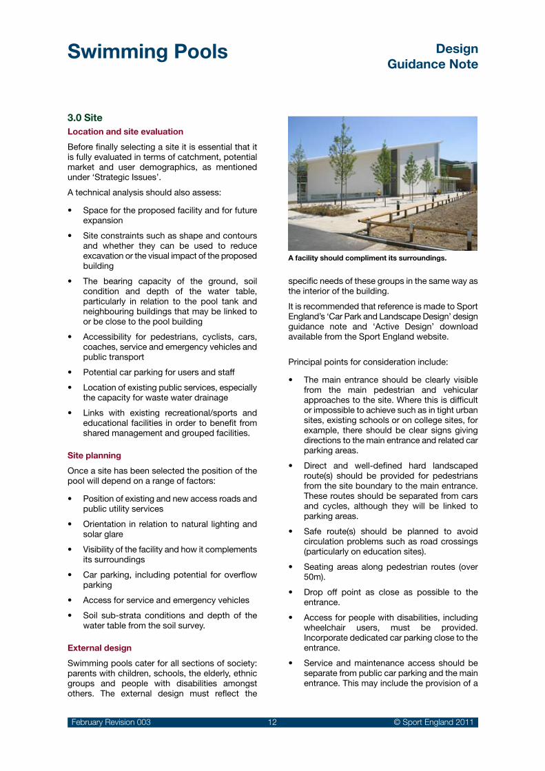
External design
Swimming pools cater for all sections of society: parents with children, schools, the elderly, ethnic groups and people with disabilities amongst others. The external design must reflect the
specific needs of these groups in the same way as the interior of the building.
It is recommended that reference is made to Sport England’s ‘Car Park and Landscape Design’ design guidance note and ‘Active Design’ download available from the Sport England website.
Principal points for consideration include:
The main entrance should be clearly visible •from the main pedestrian and vehicular approaches to the site. Where this is difficult or impossible to achieve such as in tight urban sites, existing schools or on college sites, for example, there should be clear signs giving directions to the main entrance and related car parking areas.
Direct and well-defined hard landscaped •route(s) should be provided for pedestrians from the site boundary to the main entrance. These routes should be separated from cars and cycles, although they will be linked to parking areas.
Safe route(s) should be planned to avoid •circulation problems such as road crossings (particularly on education sites).
Seating areas along pedestrian routes (over •50m).
Drop off point as close as possible to the •entrance.
Access for people with disabilities, including •wheelchair users, must be provided. Incorporate dedicated car parking close to the entrance.
Service and maintenance access should be •separate from public car parking and the main entrance. This may include the provision of a
A facility should compliment its surroundings.

Swimming Pools DesignGuidance Note
February Revision 003 13 © Sport England 2011
screened service yard for the delivery of goods and refuse collection 18.
Access to a first aid room with a dedicated •space for emergency vehicle parking and adequately sized doors for stretcher access.
Security for users with well lit public parking, •appropriate landscaping and pedestrian routes located away from areas of potential concealment.
Coach parking spaces and/or turning space, •particularly if the facility serves children from local schools or if it is a ‘destination’ venue for a wider catchment.
Secure and separate bicycle parking with •racks located under cover close to the main entrance and, preferably, visible from the office / reception.
Carefully considered evergreen planting and/•or trees to prevent unacceptable levels of glare in the pool hall.
The following factors have an impact on the external appearance of pool buildings:
Swimming pools are generally large volume •spaces. The massing, scale and volume of the
building will be key planning considerations, especially in relation to its location and context.
Activities such as diving, where high diving •boards are provided could substantially increase the overall height of the building and its scale.
Water slides or flumes (if included) can be used as an external feature to express their ‘fun’ element and provide a further visual attraction. They should form an integral part of the overall design and, ideally, be visible from the main approach to the building.
The choice of an appropriate structural •approach and material for the large spans covering the pool hall and ancillary accommodation.
It is essential that the glazing design is carefully •considered to avoid glare and specular reflection inside the pool hall 19.
The aim is to provide the optimum balance of •natural lighting that avoids gloomy conditions in the pool hall.
Windows allowing views in and out of the pool •hall need careful consideration and should be considered in relation to the need for privacy.
Windows can provide dramatic effects both •internally and externally, particularly at night.
A well positioned and landscaped pool building
18 Delivery of pool treatment chemicals will require careful consideration – see the Pool Water Treatment Advisory Group (PWTAG) publication ‘Swimming Pool Water – Treatment and Quality Standards’ and the Health & Safety Executive’s (HSE) document HSG179 ‘Managing Health & Safety in Swimming Pools’ 3rd Edition – IRSM Industry Guidance.
19 See section 4.3 on glazing and the safety implications of glare and direct sun penetration into the building and methods of mitigation.

Swimming Pools DesignGuidance Note
February Revision 003 14 © Sport England 2011
Set down point
Clear direct pedestrian footpathswith clearly de�ned cross-over points where vehicle and pedestrian routes intersect
Separate staff parkingincluding disabledparking provision
Outdoor sun bathing areas, when provided, should be positioned so that they have sunlight throughout the day
Orientation of the pool hall may becritical depending upon planning,site constraints and the needfor controlled natural lightingthroughout the day minimisingthe risk of specular glare
Consider need for space for additional car parking provision for 'specialist events' or for future expansion of centre
Screened service yard
Potential future expansion
Separate access for plant, chemical delivery and �rst aid
Access for emergencyvehicle parking
Main entrance given visual emphasis and protection by canopy
Well lit car park with simple
vehicle circulation Coa
ch p
arki
ng
Seat
road
of main entrance
Exit for use at peak times
Main
Bus stop
Bus stop
Of�ce has views
BicyclesVie
ws
out
from
poo
l hal
l
approach and bicycle parking
Assistance dogrest area Seat
Low planting allowing
Pedestrain crossing
car parking to be clearly visible
boundary
Main entrance visible from main road/ site
Prominently positioned sign indicating name of centre, facilities provided and other information
Notional site layout indicating desirable features (not to scale)

Swimming Pools DesignGuidance Note
February Revision 003 15 © Sport England 2011
Clear signage raises the profile of a building. Where possible signage should be incorporated into the overall design rather than be applied separately
An example of successful location, massing and use of materials for a small community pool

Swimming Pools DesignGuidance Note
February Revision 003 16 © Sport England 2011
4.0 Organising the building
This section considers the main elements of a swimming pool building.
4.1 Relationship of spaces
Vehicularaccess
Pool hall
FA
Cl
Admin.Entrancefoyer
Stafffacilities
S
PT
Plantroom
Serviceyard
Publicparking
Staffparking
Viewing
Social &refreshment
area
Poolchanging
R
T
Coachparking
Key:S: StoreCl: Cleaner's storeFA: First AidP: Pre/post swim showersT: ToiletsR: ReceptionPT: Public toilets
Vehicularaccess
Pool hall Sportshall
FA SCl
PT
Admin.
Entrancefoyer
Stafffacilities
Drychanging
SCl
PT
Plantroom
Serviceyard
PublicparkingStaff
parking
Viewing
Social &refreshment
area
Poolchanging
R
Future expansion
T
Relationship between main areas of a typical pool building
Relationship between main areas of a wet and dry sports centre

Swimming Pools DesignGuidance Note
February Revision 003 17 © Sport England 2011
S
Sports hall
PT
'Dry' change
Pool hall
Adminof�ces
Refreshment& viewing area
Futureextension
R
AST
FA
Futureextension
S
'Wet' change
Secondary sports spaces could be provided at �rst �oor level above the changing area
Plant room (at deep end of pool)
Sha
llow
end
Dee
p e
nd
Key:
AST
C
FA
PT
R
S
SH
T
Attendant staff accommodation
Cleaner's store
First Aid
Public toilets
Reception
Store
Showers
Toilets
Diagrammatic layout for single storey ‘wet and dry’ sports centre

Swimming Pools DesignGuidance Note
February Revision 003 18 © Sport England 2011
Diagrammatic layouts for a two storey swimming pool building
Plantroom
S
Fitnessequipment room
Space over pool hall
Admin.of�ces
Exercisestudio
'Dry'changing& toilets
Plantroom
C S
Wet change
Pool hall
PT
Refreshment& viewing area
Futureextension
R
AST
Key:
AST
C
FA
PT
R
S
SH
T
Attendant staff accommodation
Cleaner's store
First Aid
Public toilets
Reception
Store
Showers
Toilets
Spectator seating
FA

Swimming Pools DesignGuidance Note
February Revision 003 19 © Sport England 2011
4.2 First impressions
Swimming pool buildings should be attractive and well maintained to ensure lasting customer appeal. The customer experience starts with the approach to the building. The position of the building on the site and the quality of the surrounding landscaping are important elements. Scale and identity are also important design factors in both rural and urban environments.
Signage and lighting can also assist greatly in promoting the building and may be used to reinforce its external identity.
The entrance should have sufficient space to create clear orientation for customers and be inviting and non-threatening. It should also allow effective and unobtrusive supervision by staff. A positive first impression will influence visitors’ perceptions of the facility as a whole. The materials and colours will also influence the overall image of the reception area and can provide a theme for the rest of the building.
Open arrangements work well with good levels of transparency into the main areas of the building, such as the pool hall, refreshment areas and any associated fitness facilities. However, appropriate security measures will be required to avoid unauthorised access. In addition, an effective environmental separation should be maintained with pool/wet areas that have high temperature, humidity and air-borne chemicals.
A dedicated welcome area may be provided in larger centres enabling staff to provide new customers with key information on the services available.
The need to create a good first impression begins at the entrance.A positive first impression will influence visitors’ perceptions of the facility as a whole.
A well proportioned entrance with clear and direct access from the roadside
Entrance area
The entrance area should provide sufficient space for groups of people to circulate, view notices or wait for friends. At peak times the sudden influx of customers may require managed space for queuing.
An open and uncluttered reception area eases circulation and customer orientation. The entrance area should include:
Clear and easily accessed ‘in’ and ‘out’ •circulation routes
A draught lobby to reduce heat loss provided •with suitable dirt removing surface and automatic doors designed for easy access for all
A prominently positioned and instantly •identifiable reception desk
A clearly signed and direct circulation route •from the main entrance to the changing rooms via the reception desk
Key information should be provided using •clear signage to explain, for example, if changing rooms are separate ‘male and female’ or ‘shared’.
In addition:
Automatic doors need to be carefully positioned •as they can cause draughts when both sets of doors are open at the same time
Notice boards and signs are required to •indicate opening times and promote activities and services available to users
A public telephone accessible to all users.•

Swimming Pools DesignGuidance Note
February Revision 003 20 © Sport England 2011
Reception desk
Location and layout
The reception desk is of prime importance and its location, appearance and lighting will impact on the whole area. There are two main types:
Island:• Its central location occupies more space but can suit larger centres with both wet and dry facilities, where separate circulation and space for queuing are required. The arrangement can be confusing to new customers and more difficult to control. It’s isolation from offices and stores can complicate operation.
Sidewall:• located to one side of the entrance area and usually linked directly to an office/store. This option is more suitable for smaller centres allowing the counter to be unmanned during quiet periods leaving office staff to deal with the occasional customer.
The reception desk should be located to allow:
Visual supervision of the entrance/exits routes •and all adjoining areas.
Restriction of unsupervised access by •arranging the circulation pattern to pass the reception desk.
Where security is a high priority security •barriers/screens should be integrated into the design and be in close proximity to the reception. In some cases a position for a security guard may be required. Mobile or adjustable barriers might also be used at peak times.
Suitable artificial lighting for reception staff at •all times of day.
Direct access to other parts of the building •including the pool hall, social and changing areas.
Adequate queuing space between the point of •entry and the desk based on estimated numbers of users.
Cross-circulation in front of the reception desk or through queuing areas should be avoided.
Vending
Publictoilets
Seating /viewing area
Reception
Of�cesViewingarea
Glazedscreen
Poolhall
Noticeboard
S
T
Of�cesoverlookforecourt
Views of socialarea from mainapproach
Turnstile /gate
ADW
WBS
WBS Wheelchair / buggy storage areaKey
ADW Assistance dog waiting area.T Public telephone at low levelS Store
Entrance and foyer arrangement for a typical small pool building with upper floor accommodation

Swimming Pools DesignGuidance Note
February Revision 003 21 © Sport England 2011
Cash handling
The design of the reception area should take account of issues associated with handling cash. A secure area will be required for cashing up at the end of the day and possible overnight cash storage. In larger facilities, a pneumatic cash handling system may be included between remote cash points and the cash storage area.
Ventilation
Adequate ventilation should be provided to create comfortable working conditions, particularly when rooflights are sited above the reception desk.
Access Control
The initial design should anticipate the need for access control appropriate to the scale and nature of the facility. A system may include the provision of gates, turnstiles or barriers and allowance should be made for suitable access and egress for wheelchairs and pushchairs.
The access system may also incorporate a combination of control systems based upon:
Magnetic swipe/smart card or PIN code •through a membership control system.
Pay as you Go system using paper tickets, •magnetic swipe tickets and/or tokens either pre-purchased or obtained from reception.
Manually controlled access by reception staff •or a security guard.
‘Accessible Sports Facilities’ design guidance note available from the Sport England website gives details of space requirements and other requirements.
Large café/reception area overlooking pool area
Refreshment areas
A refreshment area is often located close to the main entrance with views of the pool hall. They are usually intended for those who use the pool or other activity areas, but may also be located before the reception desk in order to attract passing trade. However, in smaller centres it may not be possible to justify more than a few vending machines in association with some informal viewing areas.
The social/refreshment area should be positioned on a primary route so that it will attract visitors’ attention as they enter and leave the facility. If locating the refreshment area on an upper level is unavoidable, it should be linked by prominent stairs to the foyer and be clearly visible from the foyer area.
The size and scale of refreshment provision will depend on:
Signage begins at the entrance and should display:
Opening times and •emergency numbers
Clear directions to •help circulation and orientation
Remember that many users, in addition to partially sighted people, remove their glasses and contact lenses to swim.
Signage should be large with contrasting colours and be easily read.
See page 26 for signage required on the pool surrounds.

Swimming Pools DesignGuidance Note
February Revision 003 22 © Sport England 2011
The number of people expected to use the •building and whether the pool is linked to, or is part of, a larger centre containing dry activity areas?
Whether the pool is part of a community centre •with a bar and kitchen?
The location of the pool building and whether •the neighbouring area already has adequate refreshment facilities?
The type of menu to be offered?•
Opportunities for brand sponsorship?•
Consider the following points in the design/layout for all pool refreshment areas:
Regardless of the scale of the facility, allow •space for at least two or three vending machines positioned in a wall recess to reduce bulk and integrate within the overall design of the area. They should also be positioned to avoid repetitive/cross-circulation problems and allow space for people to stand in front of the machine. Avoid positioning machines close to door swings.
Select easily cleaned, impervious floor finishes •in areas subjected to heavy trafficking, soiling and likely spillage in order to meet hygiene regulations and minimise the risk of accidents.
Ensure that lockable storage space for vending •machine products is close by.
Provide seating and table space appropriate •to the size of facility, with good views of the pool hall and located adjacent to public toilets.
Ensure that catering facilities meet with the •requirements of the Food Safety (General Food Hygiene) Regulations 1995, including any provision for staff sanitary accommodation.
Refreshment areas can be planned as integral parts of the pool hall, or separated from it by a glazed screen. This will stop spectators distracting children during swimming lessons and avoid humidity and smells making the space uncomfortable. It will also stop drinks and food getting on to the pool side.
A barrier may, however, be sufficient, if the pool environment is well controlled and designed to provide comfortable conditions for spectators 20.
A small community pool will require sufficient space in the refreshment area for up to 20 people.
Snack bar: advice on design and layout should •be sought from a catering specialist. It is likely to include a seating area, counter and servery, food preparation area/kitchen, food storage area(s) and waste disposal facility.
Licensed bar: legal advice must be sought and •great care taken to meet the appropriate licensing requirements, particularly if the centre is run by a charity. It may need to be physically separated from other areas. Most breweries will give advice on the layout/design of the bar, including storage, if they have agreement to act as supplier.
Public toilets
Ideally toilet facilities should include male and female accessible toilets for users with disabilities. At least one unisex accessible toilet should also be provided.
For small community pools with a limited social/viewing area, a unisex WC compartment should be provided, accessible to disabled users, in addition to any accessible provision within the changing areas. For larger facilities, the provision of accessible toilets should be considered in respect of an overall access strategy. Refer to regulations and standards 21.
The social/refreshment area should be positioned so that it will attract visitors’ attention as they enter and leave the facility.
20 See Section 4.8.
21 BS8300:2001 Design of buildings and their approaches to meet the needs of disabled people.
Building Regulations - Approved Document Part M 2004 and the ‘Accessible Sports Facilities’ design guidance note available from the Sport England website.
For some programme sessions, it may be necessary to close blinds or curtains to create privacy in the pool.

Swimming Pools DesignGuidance Note
February Revision 003 23 © Sport England 2011
Cafe area can be passively supervised from reception and offers views to the pool and the building surroundings
Accommodation for children
Pushchair and pram storage: a baby buggy storage with security locks should be located close to the entrance preferably in sight of the reception area. In addition there should be sufficient space in the changing rooms for carers who prefer to use the buggies whilst changing themselves or their children.
Baby change facilities: Baby changing facilities should be easily accessible. They should be well ventilated and equipped with an adjustable changing shelf, a large purpose made nappy disposal bin and an adjacent washbasin. Provision can be within the male and female toilets and/or by providing one or more unisex accessible rooms with enough space for a parent, 2 children and a push chair (See BS 6465 and BS 8300). This may be integrated into a unisex accessible changing room with toilet or by providing a dedicated unisex accessible parent and child toilet.
Childcare facilities: Accommodation for crèches or playgroups should be located at ground level and have direct access to a secure fire exit. The best facilities are linked to the outside with a secure and protected courtyard providing outdoor play facilities.
Levels of provision vary significantly depending on whether crèche, playgroup, nursery or day-care facilities are required and the length of stay.
A licensed childcare facility will need to comply with current Ofsted National Standards 22.
4.3 Pool hall
Structural approach
The sectional profile and height of the pool hall and adjoining areas such as changing areas, may impact upon the scale of the spaces making them feel either: light and spacious; or claustrophobic and oppressive. There are a number of structural roof options that may be considered:
Simple pitched roofs•
Curved roofs with the high point centered over •the pool width
Sloping or curved mono-pitch•
Staggered or ‘saw tooth’ roofs•
Flat roofs.•
Each option has advantages and disadvantages related to the specific site, internal volume and environmental requirements.
The internal height of the pool hall may vary•
Where the ceiling or roof is flat, for a 25 x 8.5m •(4 lane) pool a minimum clear height of 3.5m should be considered
For a profiled ceiling or roof, the minimum •height for a similarly sized pool, should be between 4.5 and 6.0m at the highest point, dropping to 3.5m at the lowest point.
The volume of the swimming pool hall will have an influence on the acoustic environment and the extent of acoustic absorption material that is required to limit the reverberation time to an acceptable level. See page 75 for more details.
It helps backstroke swimmers if there are exposed structural elements or rooflights running parallel to the length of the pool, to provide a visual reference.
Glazing
Natural lighting can give life and sparkle to the pool hall interior, but it needs to be carefully controlled and considered with the general orientation of the building. Roof glazing over the length of the pool hall can provide good natural light allowing sunlight to be reflected off internal side walls whilst keeping glare, solar gain and heat loss to acceptable levels.
22 Refer to Ofsted publication ‘Crèches: Guidance to the National Standards’ published by DfES: Standard 4 – Physical Environment. Similar publications are available for other levels of childcare.

Swimming Pools DesignGuidance Note
February Revision 003 24 © Sport England 2011
Carefully controlled day lighting can add character and a connection with nature and the outside environment. However, specular reflection should be avoided.
Areas of poorly positioned direct side and/or end wall glazing can create excessive glare and solar gain. All side glazing has the potential to cause specular reflection on the water surface, from light being reflected at a low angle on to the pool water and causing the surface to appear mirrored.
In pools with large external glazed areas, particularly facing south, solar gain can also impact upon life guards, affecting comfort and effectiveness. The design of the pool hall should take this into account, by including measures to reduce or control solar gain e.g. provide shading, or effective solar control glass.
The problem can be particularly difficult when the sun is at a low angle in the winter or during the evening. The glare can mask the water below the surface and can make it extremely difficult to observe swimmers below. This has critical implications on the positioning and number of lifeguards required 23.
Specular reflection and glare can also have a serious implication for spectator seating 24.
In some instances large glazed areas have been successful. Options for controlling or minimising the impact of specular glare include:
Limiting glazing to a north facing length of the •pool, in conjunction with a reasonable amount of roof-lighting (up to 25% say)
Use of evergreen foliage or trees to significantly •reduce the amount of light and glare
Provisions of an external active solar shading •system that adjusts automatically for optimum lighting and glare control
Provision of manually operated blinds•
Automated interstitial blinds mounted within •double glazed units, linked to light sensors
Use of proprietary translucent insulated •sandwich panels that diffuse daylight and also provide some thermal insulation
The addition of underwater lighting in the pool •tank.
Capital cost and maintenance factors will need to be considered for each option.
23 The HSE publication HSG179 ‘Managing Health & Safety in Swimming Pools’ makes particular reference to the need to avoid specular reflection and minimum numbers of life guards.24
It is suggested that light from glazing or light fittings should have an angle of incident with the water surface of above 70º to avoid this problem.
Top glazing will not create reflection on the water for spectators. However side glazing may need to be screened
Glazing in a mono-pitch roof can allow safe sun penetration into the pool hall
Side lighting can cause specular glare on the pool surface limiting visibility below the water’s surface. Careful positioning of lifeguards can minimise the impact of the glare

Swimming Pools DesignGuidance Note
February Revision 003 25 © Sport England 2011
Community pool hall with an exposed roof structure top-lighting and low level windows
Artificial lighting
Artificial lighting and colour schemes will impact upon the general ambience of the space, and can affect the colour of bathers’ flesh tones and the appearance of the water.
Light fittings should be located above pool surrounds for ease of access or alternatively access from a gantry if over the pool water. Light fittings should be directed so they cause minimal glare or reflection to bathers in the water and staff on the pool surrounds. Up-lighting rather than direct lighting is preferred for general illumination as this allows a more even distribution of light, and obviates glare.
Fittings should generally be of the discharge type as the lower wattage type fittings are unlikely to meet the lighting needs. The type of discharge fitting should be selected on illumination performance, colour rendering, lamp life and energy efficiency. It is important that the fittings do not cause significant spectral change to the colour of finishes with the pool hall.
Providing reliable and evenly spread artificial underwater lighting can be difficult to achieve. Underwater areas left in shadow can be detrimental to the ability to see objects clearly in the pool. Although there are currently no regulations relating to underwater lighting, CIE* 62: 1984 Technical Report: ‘Lighting for Swimming Pools’ provides guidance. However compliance with this report can result in high capital and running costs, particularly for high end installations.
Underwater lighting therefore requires careful specialist design. This will need to take into account:
The building design characteristics, type of •pool, competition standards etc (to determine the level of illumination required).
The characteristics of the proposed fittings •(e.g. direct or indirect fittings),
The light output, angle of light distribution and •number of fittings required.
A well designed underwater artificial lighting system can provide several benefits:
Improve the appearance of the pool and pool •hall – particularly at night
Improve visibility below water level•
Improve safety within the pool • 25.
Up lighter accessible from pool side. Or alternatively for larger pools an overhead gantry. Underwater lighting should be selected based on speed and ease of re-lamping.
The use of light colours, particularly on walls and ceiling surfaces close to the pool tank, will contribute to a warm and ‘sunny’ atmosphere.
Artificial Lighting:300 lux* for most activities
500 lux* for competition
International events require higher levels:
FINA: 600 lux at the turn and start ends
Olympics: 1500 lux over the entire pool**.* Refer to CIBSE Lighting Guide 4: Sports Lighting
** Television requirements that will rarely be used in most 50m pools
25 CIE – International Commission of Lighting

Swimming Pools DesignGuidance Note
February Revision 003 26 © Sport England 2011
Well designed up-lighting can provide good overall illumination whilst achieving an attractive space. Avoid locating fittings above the pool unless accessible from a gantry
In deeper water, e.g. diving tanks, it may be necessary to provide additional light fittings in the lower pool wall, in order to illuminate the pool base.
The use of light colours, particularly on walls and ceiling surfaces close to the pool tank, will contribute to an enhanced atmosphere. Light colours are less likely to be distorted by artificial light, are more easily maintained and can aid the distribution of light through reflection, for example, from the roof soffit.
See Section 6 for more details.
Signs
It is essential that safety, directional and information signage is clear, concise, well designed and suitably positioned in all areas of the swimming pool facility. Consider all aspects that are likely to impact upon the safety of both users and members of staff. It may be necessary to undertake a risk assessment to establish what provisions are needed, particularly in respect of any unusual facilities or features.
In addition to general signage, specific signs must be provided to warn users in respect of:
Water depth – visible from the surround and •the water – to warn users of deep (>1.2m deep) or shallow water (<0.9m deep). The actual depth must be indicated – simply saying the water is shallow or deep is not adequate.
Where diving/jumping is NOT permitted.•
Restrictions on the use of features such as •diving facilities.
Ideally, information should be given pictorially as well as textually. As an example, people may not be aware of their height, and a pictorial sign at the entrance reading ‘check your height’, may prevent people getting into the water at an unsuitable place. Lettering must be big enough to be clear for those with limited vision and use contrasting colours to assist visibility.
The colour, size and style of lettering are extremely important if it is to contribute to the overall building design. Signs may be a part of the wall design and be incorporated into ceramic tiling.
The BSEN 15288-1 2008 sets out considerations for Safety–Information–Systems (5.3) in relationship to pool function, water depths and emergency routes and Health and Safety (Safety Signs and Signals) Regulation 1996 covering the design of ‘Hazard’, ‘Protection’ and ‘Mandatory’ safety categories 26.
There is scope for facility-specific signs that contribute to the corporate identity provided they conform to the general principles in the regulations.
Generally, the use of internationally recognised sport symbols and compliance with BS 5499 is recommended.
4.4 Pool tank(s)
Configuration
The various ASA classifications for swimming pools and standard dimensions are indicated in the previous section on ‘levels of competition’ on page 10. Many projects will have a 25m main pool and depending on need may have a separate learner pool/training pool. These can be in the same pool hall area or in separate spaces.
Diving from springboards and platforms should only take place in a dedicated water area that is not being used by other swimmers. Ideally this should be provided as a separate ‘diving’ pool, although such pools can also be programmed for a range of other aquatic activities, particularly if provided with a moveable floor. If, because of space or financial limitations, diving facilities have to be integrated into a 25m or 50m pool a movable bulkhead can also give the necessary physical separation.
There are general planning principles that apply:
Access to the pool hall should be at the •shallow end of the pool and must not be located near water deeper than 1.2m. A suitable safety barrier leading to shallow water should be provided if this is not possible.
Access to the pool should be arranged from •the changing room, through the toilet area and then the pre-swim shower area to promote hygiene.
26 See also HSE Health and Safety: Legal Series L 64 Guide to the Health and Safety (Safety Signs and Signals) Regulations 1996 and British Standard BS 5499: Parts 1, 2, 4, 5, 6, 10, and in particular Part 11: 2002 Water Safety Signage.

Swimming Pools DesignGuidance Note
February Revision 003 27 © Sport England 2011
Table 2 Pool surround widths preferred by the Amateur Swimming Association (ASA)
Table 3 Minimum requirements for widths of pool surrounds from BS EN 15288: Part 1: 2008 (See diagram)
Main Pool Start End Turn End Sides
20m Community
2m 2m 1.5m
25m Community
3m 2m 2m
25m Competition
4m 3m 2–3m
50m International
7m 5m 4-6m
Learner PoolAccess Side
2m
Other Side
1.5-2m
Diving Pool Board EndOpposite
EndSides
Generally 4–6m 2–4m 3–4m
International 6–7m 3–5m 4–6m
Dim ref
Location Clearance (minimum)
A Entrance wall to pool 3.0m
B Pool to wall at exit points (ladders / steps)
2.5m
C Pool to wall in areas of diving boards / platforms
3.0m
D Diving pool to wall 4.5m
E Minimum circulation space around installations / features
1.25m
F1 Distance between a diving /swimmers pool and a non swimmers pool area, in the absence of separation
4.0m
F2 Main pool to diving pool in the absence of separation
3.0m
G1 Pool to wall for pools under 300m2
1.25m
G2 Pool to wall for pools over 300m2
1.5m
Notes:
Subject to overall pool design, the ASA’s preferred 1 . general dimensions for the pool surrounds may need to be increased to meet the minimum requirements for certain prescribed areas around the pool as set out in BS EN 15288 Part 1 2008. See Table 3 below.
For international, world or Olympic competitive events 2. the pool surround widths would also need to meet the requirements of the Federation International de Natation (FINA).
Where the main pool is to be used to stage even low key 3. events with competitors sitting on the pool surrounds, the pool to wall dimension G2 should be a minimum of 2m.
Main Pool
Learner Pool
Diving Pool
EN
TRA
NC
E
A
E
G2 G2
B
F1
F2
E
C
D
G1
G1
Width ‘A’ maintained for min 2m on either side of the access point
Width ‘B’ maintained for min 1m on either side of the ladder

Swimming Pools DesignGuidance Note
February Revision 003 28 © Sport England 2011
Consideration should be given to the width of •pool surrounds separating pools. Assess whether there is a need for physical separation. A barrier can reduce the possibility of a child straying from one pool to another and can also give privacy and limit sound transmission. Separation can also enable an operator to safely shut one pool during off-peak periods to reduce lifeguard provision.
It compromises the privacy that some user •groups require e.g. people with disabilities, cultural or faith groups or single sex sessions.
It could restrict control of environmental •conditions for the different areas.
Some of these issues could be addressed by the use of a glazed screen with built in blinds or a sliding opening section. Screening with planting, or simply by increasing the acoustic attenuation of the pool hall could also be considered.
Where two types of pool are provided separately, for example, a learner and main pool, circulation to the main pool should not be via the learner pool surrounds as this may disturb users. Similarly the changing room design should achieve an appropriate degree of separation to create privacy and direct access to a learner pool.
If a separate diving pool is planned in the same pool hall as the main pool it should be positioned at the deep end of the main pool.
Privacy for some user groups
Many users will be quite relaxed to swim in a public area, but equally there may be personal, religious or cultural reasons that make people/groups uncomfortable about being visible in their swimming costumes. To engage with the whole community consideration should be given to providing a greater degree of privacy for some users groups.
It may be appropriate to provide separate changing rooms with direct access to a screened-off pool. The alternative to programme the use of the whole swimming pool(s) for dedicated sessions at certain times may be cost prohibitive (refer to Section 4.5).
Access is normally required around the •complete pool tank perimeter, and pool surrounds should conform to the minimum sizes in the table below.
Any wall buttresses or pillars on the pool •surround should have rounded corners and not restrict the required width.
There should be no changes in floor level. If •this is unavoidable, ramps with a maximum gradient in accordance with current standards and regulations should be provided, with handrails on both sides 27.
If provided, ‘fixed’ staff control points should •have good overall views of the entire pool hall and be subject to a risk assessment at the design stage.
The first aid room must be directly accessible •from the pool surround with direct access to an external hard standing area for emergency vehicles.
Pool equipment and cleaners’ stores should •be directly accessible from the pool surround.
Appropriate viewing is required for spectators •(refer to Section 4.8).
Combining two pool tanks in one hall
Combining two water areas in the same hall may be economical in capital terms but the following should be considered:
It will not necessarily reduce the numbers of •lifeguards required.
It limits the possibility to close off one pool and •leaving it unsupervised.
27 British Standard BS 8300. Building Regulations Approved Document Part M: 2004.
Refer to page 69 of this guidance note regarding slip resistance to the pool surround.
For pool floor refer to BS EN 15288 Part 1 which requires slip resisting tiles to the pool floor to a depth of at least 1.35m.

Swimming Pools DesignGuidance Note
February Revision 003 29 © Sport England 2011
Main pool The following criteria apply for competition pools:
Length of pool tank:• competitions are held in 25 and 50m pools with end walls that are parallel, and at right angles to both the swimming course and water surface. Maximum tolerances to the finished surfaces are measured from 0.3m above + 0.8m below the water surface and must be as follows:
25m pool: 25.000m (-0.00m + 0.030m) 50m pool: 50.000m (-0.00m + 0.030m)
However, when removable touch panels are used in the pool (as part of an automatic officiating timing system) the above tolerances must not be exceeded and the dimensions to the tiled wall faces need to be adjusted to:
25m pool: 25.020m (-0.00m + 0.010m) 50m pool: 50.020m (-0.00m + 0.010m)
Dimensions will need to be certified by a surveyor proposed or accepted by the governing body 28.
Width of pool tank:• depends on number and width of swimming lanes and extra margins of water required for the two outer lanes to improve swimming conditions. The minimum lane width is 2.0m for 25m pools. Competition pools used at regional, national and
international levels should be provided with lanes of 2.5m width.
Water depth:• should be not less than 0.9m in shallow water areas of small 20m and 25m community pools. However, where a learner pool is provided and in larger pools, the depth should be increased to a minimum of 1m to facilitate tumble turns.
The depth of the water can also affect the speed that swimmers can attain. Pools used for swimming competition under FINA rules, require a minimum water depth of 1.35m extending from 1m to at least 6.0m from the end wall for pools with starting blocks and elsewhere a minimum depth of 1m is required. However 1.8m 29 is preferred, increasing to 2m minimum or 3m preferred for World and Olympic events. Dedicated competition pools may be set at a constant depth.
Colour of tank finish:• white or pale blue finishes are preferred as they have high reflectance factors. This makes it easier to see swimmers below the water and to judge by eye the clarity of the water.
28 Federation International de Natation Amateur (FINA) http://www.fina.org/ and the Amateur Swimming Association (ASA) http://www.britishswimming.org/
D
S
P P
Primary Unisex Access Route
Sensitive Group Access Route (e.g. women / ethnic use)
C - ChangingS - Sauna SuiteD - Dedicated Fitness SuiteP - Swimming Pool
C
C
C D
S
P P
Primary Unisex Access Route
Sensitive Group Access Route (e.g. women / ethnic use)
C - ChangingS - Sauna SuiteD - Dedicated Fitness SuiteP - Swimming Pool
C
C
C
A layout designed with a dedicated suite of changing, fitness and sauna for sensitive groups
29 The ASA and ISRM stipulate a minimum depth of 1.8m for the teaching of shallow entry dives from the pool side. See ISRM publication “Diving and Jumping into Swimming Pools and Open Water Areas” which also has advice on the use of Starting Platforms and the ASA Competitive Start Award. For the teaching of shallow dives where the freeboard is greater than 0.38m the FINA standards for the depth of water under a 1m platform should apply.

Swimming Pools DesignGuidance Note
February Revision 003 30 © Sport England 2011
Pool tank profile:• should be considered in relation to the range of activities to be accommodated and whether movable floors and bulkheads are planned (see from page 32).
For safety, variations in water depths below 0.8m should be achieved through gradients of 1 in 20 (5%). For variations between 0.8m and 1.35m, gradients should be no steeper than 1 in 17 (6%) 30. Where pool depths continue down to 1.5m or 1.8m the same gradient should preferably be continued. See diagram for tank profiles, depths and gradients on page 32.
The 1.35m depth line should be conspicuously marked on the pool floor by a contrasting line to identify the start of deeper water.
Dedicated competition pools may be set at a constant depth of 1.8m preferred, or 2.0m minimum for World or Olympic competition (see FINA handbook).
Pool edge detail:• a ‘deck level’ edge is the most effective and attractive option. This allows pool water to constantly overflow the edges of the pool tank and drain into a continuous channel set into the pool surround. The channel can be positioned at the pool edge or set back behind a tiled margin of approximately 0.30m.
Deck level edge pools have advantages over the older freeboard (scum channel) pools:
Easier pool access/egress O
Improved surveillance of the pool tank from O
the poolside
Improved air movement across the surface O
of the pool, enabling more effective removal of airborne chemical pollutants
Improved surface draw-off removing O
pollutants from the water surface more efficiently
Reduction in water turbulence, improving O
conditions for swimmers in the outer lanes and people learning to swim.
The deck level edge must be designed to allow swimmers to obtain a grip and also have a dark coloured edge demarcation to allow the edge of the water to be more easily seen by swimmers and those on the pool surround.
Raised pool ends:• provide a clearly visible vertical surface in deck level pools for tumble turns to be safely executed and remove the need for separate turning panels. The ends should be 0.3m above the water level and incorporate a hand grip. Where the water depth permits they can be used to teach diving. They are an advantage for competitions and training, but are not required for fitness swimming. They allow easier integration of automatic officiating equipment for competitive events. For occasional competition use, temporary starting platforms and turning boards should be used. The ASA advocates that turning boards should be installed during lane swimming sessions for fitness in all lanes but particularly in the fast and medium pace lanes.
Lane markings:• positioned on the pool tank floor and end walls in the centre of each swimming lane, they help swimmers judge the end of the pool tank when turning and are required for competition. They should be dark blue or black, contrast with the pool tank finish, and be set out to meet ASA/FINA standards.
Vertical access steps and ladders:• should be recessed flush with the pool tank walls and positioned at each end of the pool tank about 1m from the end walls. Extra steps can be provided mid-way along the sidewalls. For diving tanks, steps should be positioned to allow divers to swim away from rather than towards the diving boards after a dive.
Rest ledges:• are useful where the water depth is greater than 1.8m. They should be fully recessed into the finished surface of the tank wall at a water depth of not less than 1.2m.
Underwater lighting:• can contribute to a pleasant atmosphere and if of sufficient intensity 31 can help staff see people beneath the water more easily. Lighting should only be installed in the sidewalls of the tank.
Underwater windows:• are useful for surveillance in those pools used for serious training and competition. These are normally installed in the side walls of the tank. However they can be installed in the end walls if more than 0.8m below the water surface to avoid interfering with turning.
30 BSEN15288:1:2008 - Sport England have adopted the ‘preferred’ gradients (rather than the ‘minimum’ gradients) as their standard.
31 CIE 62 suggests that an underwater lighting intensity of 1000-1500 lm/m2 would be required to help reduce the veiling effect of reflected light on the water surface.

Swimming Pools DesignGuidance Note
February Revision 003 31 © Sport England 2011
Lane ropes
300
B
A C
End wall target
A
D
F
Raised pool end
E
E/2 E/2
E
Racing Lane width
H
H
see table
Lane markings
15m
to
cros
s lin
e
Detail 1
Key plan
Detail 1
Detail 2
Touch panel J
Elevation of end walls
ASA/FINA competition pool dimensional requirements.
All sizes in metres ASA ASA FINA
Pool Length X 25.02 50.02 50.02
Pool Width Y 8.5/10.5/13/17 17/18/19/21/25 21/25
Width of lane markings, end lines, targets A 0.2 0.25 0.25
Length of end wall targets B 0.5 0.5 0.5
Depth of centre of end wall targets C 0.3 0.3 0.3
Length of lane marker cross line D 0.8 1.0 1.0
Width of racing lanes (Pool widths 8.5 - 17m ) E 2.0 2.0 -
Width of racing lanes (Pool width 18m ) E 2.125 2.125 -
Width of racing lanes (Pool width 19m ) E 2.125 2.25 -
Width of racing lanes (Pool widths 21m / 25m ) E - 2.50 2.50
Distance from cross line to end wall F 2.0 2.0 2.0
No of Lanes (Pool width 8.5m) G 4 - -
No of Lanes (Pool width 10.5m) G 5 - -
No of Lanes (Pool widths 17 - 25m) G 8 8 8/10
Outer Margin (Pool widths 8.5m / 10.5m)) H 0.25 - -
Outer Margin (Pool widths 13 - 21m) H 0.50 0.50 0.50
Outer Margin (Pool width 25m) H - 2.50 2.50
Touch Panels J 1.90 2.40 2.40
Dimensions A, B, C, D, F and J are subject to a +/- 0.05m tolerance.
FINA 50m pool
ASA 25 or 50m poolLane widths of 2m relate to 17m wide pools used for training purposes.
Touch panels for lane widths other than 2.0 and 2.5m (e.g. 2.125 or 2.25m) will require bespoke manufacture.
15m
to
cros
s lin
e
X
Y
Detail 2
Depth to centre of end wall target
The lane markings are centred on each swimming lane at E centres
4
2 3
1
1
1
1
1
1
2
2
5
2
1
3
4
5
5
Lane ropes
300
B
A C
End wall target
A
D
F
Raised pool end
E
E/2 E/2
E
Racing Lane width
H
H
see table
Lane markings
15m
to c
ross
line
Detail 1
Key plan
Detail 1
Detail 2
Touch panel J
Elevation of end walls
ASA/FINA competition pool dimensional requirements.
All sizes in metres ASA ASA FINA
Pool Length X 25.02 50.02 50.02
Pool Width Y 8.5/10.5/13/17 17/18/19/21/25 21/25
Width of lane markings, end lines, targets A 0.2 0.25 0.25
Length of end wall targets B 0.5 0.5 0.5
Depth of centre of end wall targets C 0.3 0.3 0.3
Length of lane marker cross line D 0.8 1.0 1.0
Width of racing lanes (Pool widths 8.5 - 17m ) E 2.0 2.0 -
Width of racing lanes (Pool width 18m ) E 2.125 2.125 -
Width of racing lanes (Pool width 19m ) E 2.125 2.25 -
Width of racing lanes (Pool widths 21m / 25m ) E - 2.50 2.50
Distance from cross line to end wall F 2.0 2.0 2.0
No of Lanes (Pool width 8.5m) G 4 - -
No of Lanes (Pool width 10.5m) G 5 - -
No of Lanes (Pool widths 17 - 25m) G 8 8 8/10
Outer Margin (Pool widths 8.5m / 10.5m)) H 0.25 - -
Outer Margin (Pool widths 13 - 21m) H 0.50 0.50 0.50
Outer Margin (Pool width 25m) H - 2.50 2.50
Touch Panels J 1.90 2.40 2.40
Dimensions A, B, C, D, F and J are subject to a +/- 0.05m tolerance.
FINA 50m pool
ASA 25 or 50m poolLane widths of 2m relate to 17m wide pools used for training purposes.
Touch panels for lane widths other than 2.0 and 2.5m (e.g. 2.125 or 2.25m) will require bespoke manufacture.
15m
to c
ross
line
X
Y
Detail 2
Depth to centre of end wall target
The lane markings are centred on each swimming lane at E centres
4
2 3
1
1
1
1
1
1
2
2
5
2
1
3
4
5
5
Table 4 ASA/FINA competition pool dimensional requirements

Swimming Pools DesignGuidance Note
February Revision 003 32 © Sport England 2011
Examples of tank profiles for 20m and 25m pools
0.9m 0.9m 1.5m1.5m1.35m
4.0m 5.8m20.0m
10.2m**
Water depth
Water depth 1.0m* (0.9m dotted)
1.8m2.0m
6.01m
4.31m 2.01m@ 1:10
25.02m +/-0.01m (25.0m if no timing pads)
1.35m
For small rural community pools without a separate learner pool, the shallow water depth can be reduced from 1.0m to 0.9m which is considered more appropriate for young children and teaching.
1.5m water depth allows basic life saving / teaching /training and water based aerobics to be practiced.
Teaching recreational bathing, �tness swimming and training can be accommodated in this pro�le.
Slopes should not exceed 1 in 17 in water depths less than 1.35m - the gradient should be continued down to depths of 1.5m where possible.
1.0 to 1.35m is the most useful depth for teaching.
1.8m is the advisable minimum depth for life saving practice.
Races should be started from the deep end of the pool, subject to it being more than 1.35m deep for 6.0m.
Slopes should not exceed 1 in 17 in water depths less than 1.35m - the gradient should be continued down to depths of 1.5m / 1.8m where possible.
The contour of the �oor allows the pool to be used for the teaching of shallow entry dives at the deep end but is not suitable for other types of diving or the use of diving boards. If diving boards are to be provided then �rstly, the water depth will need to comply with FINA Facilities Rules and secondly the area under the boards will need to be physically separated from the other activities taking place in the pool, for example, by the use of a bulkhead and lastly, the separated area will need its own supervision.
Pool surfaces should be clearly marked to indicate the 1.35m water depth location
Raised ends for signi�cant competition use shown dotted
Pool surfaces should be clearly marked to indicate the 1.35m water depth location
18.7m**@1:17 gradient
17.0m**@1:17 gradient
** Pool �oor gradients in shallow water areas < 1.35m deep should be as gentle as possible but should be < 1:17 (6%)
** Pool �oor gradients in shallow water areas < 1.35m deep should be as gentle as possible but should be < 1:17 (6%)
20m pools - general guidance
25m pools - general guidance
* 1.0m is the preferred minimum depth for tumble turns. 0.9m is acceptable where a separate learner pool is not provided.

Swimming Pools DesignGuidance Note
February Revision 003 33 © Sport England 2011
Lane ropes spaced at 2 m centresfor combined teaching/learner pools
13m
7 m
7-13m
13 - 20 m
A
A
0.8m 0.8m
0.6m 0.6m
0.6m0.9m
7 m
Steps should be divided by handrails and a barrier rail provided at the ends to prevent children from jumping onto the steps
0.6m
0.9m
0.6m
0.9m
Decorative tiles spaced at 1.5m centres along the centre of each lane
Lane rope
Example of a stand alone learner pool layout
Example of a combined teaching/learner pool typical layout
Section A - A Pool Pro�le.
A
A
Learner and learner/training pools
The ASA recommend that Learner Pools are provided with an integral movable floor to increase programme flexibility for community use. Refer to page 39 for further details.
The following criteria apply:
Length:• not critical although 13.0m should be the preferred minimum length and 20.0m is a preferred length if the pool is also used for training.
Width:• should be wide enough for learners to
make several strokes to get from one side to the other – 7.0m is acceptable.
Water depth: • 0.6m sloping to 0.8m or 0.9m preferred across the width if the pool is used for training. This can be accommodated in various layouts.
Colour of tank finish:• white or pale blue.
Pool tank profile:• the shallowest part of the pool should be at the base of the pool access steps, with the pool bottom sloping to its deepest point, preferably across the pool width.

Swimming Pools DesignGuidance Note
February Revision 003 34 © Sport England 2011
Pool tank gradient:• should be no steeper than 1 in 17 (6%) for water of less than 1.35m and 1:20 (5%) for water less than 0.8m 32.
Pool tank markings:• can be provided for interest and to space school groups evenly throughout the pool. These should not be a colour or a shape that could be confused with a child in the water. Markings in lines can help a child to learn to swim in straight lines.
Access steps and ladders:• ladders must be fully recessed. Steps should be positioned along the length of the pool rather than at the pool end and should be recessed within the pool surround. Steps should be gently graded with treads of not less than 0.3m and risers of approximately 0.14m. There is a need for handrails to help children and ambulant disabled people walk down the steps into the pool.
Pool edge detail:• It is generally agreed that a deck level pool, with the water level the same as the surround, has advantages. A hand grip for swimmers and an edge with a distinctive colour contrast should be provided.
32 ‘BSEN 15288: Part 1: 2008 Swimming Pools: Safety requirements for design.’
Learner/training pool with handrails and shallow steps
Diving pools
‘Managing Health and Safety in Swimming Pools’ states that as a general principle, when new pools are being designed, diving stages and springboards
should only be installed over a separate purpose designed pool.
However, if diving boards are incorporated into a swimming pool then the area of pool needed for safe diving will need to:
Be physically separated from all other activities •taking place in the pool e.g. a movable bulkhead
The water depth will need to comply with FINA •Facilities Rules for Diving
The diving area will need its own independent •supervision.
The addition of a movable floor can also increase flexibility.
The following criteria apply:
Minimum dimensions:• the tank and the boards should conform to the minimum dimensions set out in the FINA Facilities Rules for Diving. However, the preferred dimensions should be adopted where possible. For Olympic pools, the preferred dimensions become the minimum requirement.
A movable floor will allow the pool to be used for a wider range of activities but if provided, the tank depth should be increased to accommodate the movable floor. The overall dimensions could be increased to suit the other activities, such as synchronised swimming and water polo.

Swimming Pools DesignGuidance Note
February Revision 003 35 © Sport England 2011
ASA/FINA Diving Requirements (Plan)
3m springboard
3m springboard
1m springboard
1m springboard
3m & 7.5m platforms(stacked)
10m platform
1m & 5m platforms(stacked)
Examples of dedicated diving tank layouts (incorporating synchronised diving)
FINA standards recommend that diving platforms are not stacked above each other, but in the event that this is unavoidable, clearances and set-back of plummet lines need to be provided. This maybe a requirement where pool size does not allow springboards to be located opposite the platforms.
3m springboard
3m springboard
1m springboard
1m springboard
7.5m platform
10m platform
5m platform
3m platform
1m platform
Preferred diving pool size 25 x 21 or 25m for two sided use (right hand example above). Other formats depend upon available space - a minimum diving tank to accommodate a full range of diving platforms and twin 1m and 3m springboards will be 25 x 15.75m based upon minimum FINA standards and stacking (left hand example above).
1m springboard
3m springboard
The ASA required diving provision is for: 3m wide platforms at 3, 5, 7.5 and 10m levels. There should also be 3 No x 1m and 3m springboards where possible2 No x 1m and 3m springboards is the minimum requirement to accommodate synchronised diving at training and competition levels. However the level of provision will depend upon the pool size and space available. Harness rigs should be provided for 1 x 1m and 1 x 3m springboard for training purposes.
Examples of dedicated diving tank layouts (incorporating synchronised diving).
FINA standards recommend that diving platforms are not stacked above each other, but in the event that this is unavoidable, clearances and set-back of plummet lines need to be provided. This maybe a requirement where pool size does not allow springboards to be located opposite the platforms.
Preferred diving pool size 25m x 21m or 25m for two sided use (right hand example above). Other formats depend upon available space - a minimum diving tank to accommodate a full range of diving platforms and twin 1m and 3m springboards will be 25m x 15.75m based upon minimum FINA standards and stacking (left hand example above).
The ASA required diving provision is for 3m wide platforms at 3, 5, 7.5 and 10m levels and 2No. 1m and 3m springboards being the minimum requirement to accommodate synchronised diving at training and competition levels but preferably there should be 3No. 1m and 3m springboards where possible. However the level of provision will depend upon the pool size and space available. Harness rigs should be provided for one 1m and one 3m springboards for training purposes.
Colour of tank finish:• walls can be white or pale blue. A dark-blue floor is preferred as this, in conjunction with agitation of the water surface by water sprays, assists divers in seeing the water surface and will minimise accidents.
Pool tank profile:• dimensions will be determined by FINA requirements and whether a movable floor is installed. Where the diving tank also acts as a 25m training pool, the lane markings should be provided in a colour which contrasts with the floor of the pool. The makings should be 0.2/0.3m in width and each lane shall end 2m from the end walls of the pool with a distinctive cross line 1.0m long. Target lines should be provided on the end walls in the centre of each lane. These should extend without interuption to the floor of the pool and have a cross line 0.5m long 0.3m below the surface of the water.
Pool edge details:• Should be level with the water (i.e. without a raised hand grip lip) to help swimmers maintain contact and balance before diving. Raised sections of the surround
with a flat edge can also be helpful for teaching and coaching.
Ladders and steps:• should be recessed. They should be positioned to encourage divers to follow a safe route to rapidly exit the water after completing their dives, while avoiding the danger areas of other boards.
The type and positioning of steps will be affected by the board layout, other activities accommodated in the pool and whether a movable floor is planned.
Rest ledges:• if provided, must be fully recessed at a water depth of not less than 1.2m.
Surface agitators: • a FINA requirement to help divers in their visual perception of the water surface. Normally the agitation is made via water sprays and directed on to the surface of the water.
Bubbler:• a ‘bubbler’ is installed on the pool floor to provide a compressed air cushion of bubbles to help protect divers from injury.

Swimming Pools DesignGuidance Note
February Revision 003 36 © Sport England 2011
platform
platform
Lifeguard Position
Danger area
Danger area
Danger areaplatform
*
ASA/FINA diving requirements (Section)
Platform
Platform
Plummetline
Plummetline
3m Springboard
1m Springboard
ASA/Fina diving pool requirements vary depending upon diving height and board/platform layout and setting out - refer to tables produced by the ASA/FINA. It is common for a rectangular diving tank to be used with a movable �oor to allow more �exible use of the pool, rather than the pro�le shown within the ASA/FINA standards, provided that the pool full�ls the dimensional requirements.
ASA/FINA recommend that diving platforms are not stacked aboveeach other. However, where this is unavoidable the lower platformsare set back up to 1.25m, whilst still maintaining the distance back to the pool wall. This may impact upon the pool tank size.
0.75 - 1.25m
0.75 - 1.80m
9 - 13.5m
Lateral spacings between platforms, springboards and pool sides vary substantially anddepend upon FINA standards and board heights
Platform under platform
Platform orspringboard
Ensure that ASA/FINA headroom clearancestandards (shown dotted) are followed as these are substantial, and will impact on diving layoutand roof structure design & height.
Underwater lighting, windows and •surveillance: see page 30.
Training Harnesses: • consideration should be given to the provision of training harnesses attached to the roof structure for some of the boards.
Shower and spa pool: • used by divers to warm up and relax muscles while out of the water for long periods.
Dry land training area:• an estimated 30% of diver training is in a dry springboard training area. Ideally situated adjacent to the diving pool and equipped with trampolines, dry boards with foam landing areas, weight
The diving pool overall dimensions could be increased to suit other activities, such as synchronised swimming and water polo.
Arrows show the quickest and safest route from the danger areas.
training area and training harnesses.
Lighting:• should be an even level of 600 lux measured at 1.0m above the surface of the water. Glare/specular reflection on the water surface must be avoided. A similar standard of lighting should be provided in the dry land training area.
See FINA web site for current dimensions for diving facilities.

Swimming Pools DesignGuidance Note
February Revision 003 37 © Sport England 2011
Easy access to the water
An appropriate combination of recessed ‘easy going’ steps, recessed ladders, ramp, submersible platform and / or hoist should be provided to allow easy access to and from the water for all users. In this respect deck level pool surrounds are preferred.
See separate Sport England Design Guidance Note ‘Accessible Sports Facilities’ for further details.
Pool transfer aids should be provided for all pools. The type of aid will depend on the needs of the user, however all pools should provide a demountable hoist and a metal socket fixing mounted into the pool surround.
A permanent ramp or walk-in steps are the preferred option to assist wheelchair users and people with walking difficulties. Portable steps/stairs should not be seen as an alternative, but part of the standard equipment to help particular people with disabilities.
Recessed ‘easy going’ steps allow easy access to and from the water for all users
Ramp access and projecting platform adjacent to a teaching area in a specialist pool

Swimming Pools DesignGuidance Note
February Revision 003 38 © Sport England 2011
Table 5 Pool Equipment taken from Sport England Guidance Note: Accessible Sports Facilities
Typical assisted pool hoist to provide access to the water
A submersible pool surround lift integrated into the pool as part of the pool surround can provide a dignified access to the pool for wheelchair users
Self-propelling waterproof 1 2 3 * * chairs (min)
Poolside hoist l l m (single position)
Poolside hoist m m l l l (multiple position)
surround lift m m mmm
Mobile hoist m m mmm
Portable easy going steps m l l l
Minimum number of 4 4 8 * * full-height lockers
chair accessible lockers 4 4 8 * *
Changing mats l l l * *
Key: lRequired m Recommended * As main pool provision
20m
sw
imm
ing
pool
25m
sw
imm
ing
pool
50m
sw
imm
ing
pool
Lear
ner p
ool
Div
ing
tank
Submersible pool
Minimum number of wheel-

Swimming Pools DesignGuidance Note
February Revision 003 39 © Sport England 2011
Movable floors and bulkheads
Movable floors are being used more extensively to change the water depth over part or all of the pool tank area in order to achieve greater programming flexibility. They allow more activities to be accommodated within a single pool area or improve activities that may be compromised by a fixed depth of water.
There is evidence of greater through-put and reduced net operating cost where they are used, particularly for 50m pools.
The use of this technique to create a ‘dry’ activities space is usually limited by the wet humid conditions within the pool hall. However learner pool floors, which can be raised to the level of the pool deck surround, are sometimes used as a holding area for competitors when an event is taking place in the main pool.
Movable floors can be adjusted from a depth of a few centimetres for carer and baby classes to a safe depth of 5.0m for a person diving from a 10.0m diving board.
With a main pool and learner pool configuration as recommended by the ASA there are a number of locations in which a movable floor can provide benefits.
Where a movable floor is provided as part of a learner pool, automatically folding steps (as shown
in the illustration) can be integrated with the movable floor to allow mother and child, or those with ambulant disabilities, to access the pool with greater ease, regardless of its set depth.
There are two types of bulkheads – those which traverse laterally and when not in use are stationed at one end of a pool, and those which move vertically and when in their lowered position are housed in a recess in the pool floor.
Bulkheads can be used to:
Divide the water area so it can be used for •different activities simultaneously. This is often desirable for safety reasons.
Reduce the length of an existing pool to 25m, •
The bulkhead allows divided simultaneous use of two areas of a single swimming pool
Movable floors allow a wide variety of uses

Swimming Pools DesignGuidance Note
February Revision 003 40 © Sport England 2011
which is the length recognised by the ASA for training and competition.
Provide measurable distances where accuracy •is important.
Provide a safety barrier to the edge of a •movable floor.
See Section 6 for construction issues.
Self depositing steps can be integrated into a movable floor providing easy access whilst maintaining a fully flexible pool
Examples of flexible pool use where a bulkhead and movable floor is provided
Depending upon the movable floor selected, it may be possible to adjust the floor from level to an inclined gradient. However any gradient must be limited to 1 in 15 and be provided with a slip resistant surface.
Stage 1
Stage 2
Stage 3Depending upon the movable �oor selected, it may be possibleto adjust the �oor from level to a inclined gradient. However any gradient must be limited to 1 in 15 and be provided with a slipresistant surface.
Examples of flexible pool use where a bulkhead and movable floor is provided.
Varie
s
16.66m 1.0m
25m
Fitness swimmingClub trainingAdvanced lessons
Casual lengthsOver 50's
Parent/toddler lessonsUnder 5's quiet swim
Casual lengthsImprover lessons
Aqua FitSub-Aqua/Diving
Casual lengthsAdult quiet swim
Parent/toddler lessonsJunior lessons
Wheelchair entryDry land exercise
Mode 1
Mode 2
Mode 3
Mode 4
Mode 5
Pool Plan
Bul
khea
d
Self depositing steps

Swimming Pools DesignGuidance Note
February Revision 003 41 © Sport England 2011
4.5 Changing facilities
Swimming pool changing can be designed with either open-plan single-sex areas or as a ‘village changing’ unisex area with individual cubicles.
The village changing arrangement is usually preferred for the various modes of use. Village changing can provide:
Greater flexibility to accommodate varying •mixes of male and female users, including family changing and changing for people with disabilities.
Flexibility to allow staff of either sex to •supervise, clean and maintain the area 33.
Minimise any perceived sense of insecurity for •sensitive users 34 by well designed changing rooms that offer privacy through adequately sized, good quality cubicles.
There is scope for variations in both systems with the addition of group single sex changing rooms, buffer rooms and additional cubicles that are discussed later. This can give a degree of choice for user groups. It is recommended that early consultation takes place with stakeholder groups with a view to understanding the full requirements of all user groups.
Changing areas often attract criticism in otherwise well-designed facilities. The key issues are:
Adequate spatial allowance for users to •maintain a sense of personal space
Capacity to cope with peak times, without •pinch points, particularly between cubicles and lockers
A flexible layout for varying ratios of male and •female users
Areas that can be closed off for privacy for •sensitive groups with direct access to toilets /pre-cleanse / pool water
A suitable environment avoiding extremes of •humidity, air movement (draughts) and temperature
Simple and clear circulation routes between •point of entry and the pool hall
Well designed cubicles and lockers with •suitable materials and robust fittings which, together with good supervision, help to resist vandalism
A number of hose points to limit the length of •hoses and adequate falls to drain to aid efficient cleaning and maintenance of the changing, toilet and shower areas.
Design features that can help to achieve bright, crisp and airy surroundings for users include:
A strategic use of natural top lighting e.g. roof •lights can improve the appearance of the changing area and may minimise the use of artificial lighting.
Bright and warm artificial lighting and •maximising the ceiling height.
Use of bright contrasting colours to walls, •cubicles, lockers, signage and graphics.
33 A variation, used in some European facilities separates wet and dry circulation. This needs more space and the layout can be confusing but has advantages in reducing the migration of dirt into wet areas, selection of appropriate flooring and the cleaning of the floor.
34 See Women Sports Foundation UK.http://www.wsf.org.uk/ http://www.whatworksforwomen.org.uk/
It is recommended that early consultation takes place with stakeholder groups with a view to understanding the full requirements of all users.
Village changing with view from the pool side

Swimming Pools DesignGuidance Note
February Revision 003 42 © Sport England 2011
General planning principles
For ease of operation and supervision organise •the route from reception to the pool in a logical sequence.
Make vanity areas spacious enough to prevent •congestion close to the entrance. Take into account bathers entering and leaving in addition to those using the vanity area.
Make space close to the entry point and within •sight of the reception for storage and parking of baby buggies, prams and wheelchairs. Also make adequate space allowance for their storage within the changing area.
Ensure that single-sex changing areas and •toilet provision are well screened from common areas for privacy.
Plan the layout to allow effective surveillance •by staff.
Through routes need to be clearly defined and •lockers should be positioned in close proximity to the changing benches or cubicles.
Position toilets on the access route to the pool •and ensure pre-swim showers are located after the toilets and immediately prior to the entry into the pool hall.
Pool changing should not be combined with dry changing. Pool changing areas generally have higher temperatures and humidity, lack individual showers, and are more difficult and expensive to keep clean.
To avoid cleaning problems, minimise repetitive circulation where users from the wet side use the same routes as those from the dry side.
Changing layouts
The following diagrams show typical arrangement for single sex changing and changing village.
Single-sex open-plan changing accommodation should allow flexibility to manage variations in male/female mix ratios. This can be achieved with group changing rooms located between the changing rooms, with interlinking lockable doors, to become ‘buffer’ changing that can be quickly allocated to either male or female use.
Some user groups will have specific requirements. For example, a school pool will require more group changing rooms, a specialist pool for people with disabilities will require mainly large accessible changing cubicles with minimal group changing. Specific requirements should be determined by appropriate consultation prior to preparation of the brief.
A standard changing village with cubicles could be divided up into dedicated zones for male or female use for particular programme sessions.
Lockable group or team changing rooms for school classes, competition and club use can be included as an additional facility. They can also be used as an overflow facility during busy periods.
At off-peak times, the buffer or group rooms will remain locked unless needed for school or group use. At peak times they can be opened up to provide overspill male or female changing.
The changing village is the preferred option for most new pools and a number of existing pools have converted from single-sex changing to mixed-sex changing villages. For most community swimming pools a mixed-sex changing village with at least two lockable group changing rooms offers the most cost-effective and easily managed arrangement.
Signs must give clear information using lettering which contrasts clearly with it’s background to improve visibility and reassurance to users. Braille should be incorporated and imagery is also beneficial

Swimming Pools DesignGuidance Note
February Revision 003 43 © Sport England 2011
Table 6 Analysis of types of changing room layouts
Function Mixed-sex village changing Single-sex, open plan changing areas
UsabilityAdvantages
Simple, direct circulation routes with views to and from the pool and other areas.Individual privacy.Cubicles popular with women (if designed to allowing sufficient personal space and feeling secure and well supervised).Layout can be designed to ensure users pass toilets and showers.Adjacent lockable group changing rooms can also give additional capacity at busy times.
At quiet times, users may use as much spaces as they wish.Vacant changing spaces can easily be identified.School groups can be more easily supervised.Layout can be designed to ensure users pass toilets and showers.Buffer rooms can be used for lockable groups changing. Popular with club groups.
Disadvantages Can be difficult to find a vacant cubicle.Might be difficult for school groups to be supervised and there is the additional complication of storing pupils clothes in the lockers. More mingling of fully clothed and wet users.
Less open circulation routes to and from the pool and other areas.Lack of individual privacy.Cubicles may be required in addition.Privacy barriers required at point of entry to the changing room and at the pool hall and makes more complex and restricted circulation pattern.
Flexibility Advantages
All changing spaces and lockers are available to all users giving flexibility to accommodate any proportion of male and female users. Parents can share a cubicle with children of opposite sex.Family groups can change together.
Individual bench changing spaces are not defined making it possible to accommodate more users during busy periods.
Disadvantages Location of toilets may cause repetitive/cross-circulation where rows of cubicles and lockers open directly into the pool hall.
Unless buffer changing rooms are provided, there is no flexibility to accommodate different proportions of male and females.Family changing with parents and children of opposite sex is impossible, except for young children. Provision may need to be provided elsewhere.
Accessibility Advantages
Helpers can accompany people with disabilities of opposite sex.Some cubicles can be sized to give privacy to people with disabilities.
Sufficient free space can be provided so that people with disabilities can move easily around the changing area.
Disadvantages It can be difficult for people with disabilities to move around in the cubicles and changing areas.
People with disabilities require an assistant of their own sex.More complex circulation caused by privacy screens can restrict circulation.
Cleanability Advantages
Row of cubicles can be taken out of use during cleaning (subject to the layout and the location of floor drainage gullies).
Large, relatively uncluttered floor areas should be easier and quicker to clean.If buffer changing rooms are provided these can be locked during off peak times.
Disadvantages Cleaning has to be confined to relatively small areas at a time and may take longer because of the need to work around cubicles and their supports.
Large open-plan areas may be more difficulty to close off at times of low demand.
Manageability Advantages
Staff of either sex can supervise, clean and manage the entire changing area.
The entire changing area is normally visible and can be easily supervised.
Disadvantages There can be hidden areas that are difficult to supervise.
Requires two members of staff of opposite sex to supervise the two areas and to deal with problems such as the opening of lockers.
Capital cost Advantages
Minimum number of lockers required. Additional lockers required for different peak demands of a particular sex.
Disadvantages More space per person for a cubicle based layout.
Operating costs Advantages
Reduced staffing cost for supervision.
Disadvantages Cubicles require additional maintenance. Staff of both sexes required for supervision.Cannot be supervised from the pool side.

Swimming Pools DesignGuidance Note
February Revision 003 44 © Sport England 2011
Calculating numbers
The standard methodology for assessing the maximum number of changing spaces required is based on:
Number of spaces required for a steady state •condition i.e. when there is a steady flow of bathers into and out of the pool.
Additional spaces to accommodate call-out •groups: more commonly referred to as session groups. During peak periods the time spent in the pool may have to be limited and this is normally achieved by giving bathers a coloured wrist or ankle band. Each session has a set minimum time after which the users are ‘called out’ of the pool depending on their band colour to make way for others.
Table 7 Accessible changing and toilet provision
20m
Com
mun
ity P
ool
25m
Com
mun
ity /
Com
petit
ion
Poo
l
50m
Com
petit
ion
Poo
l
Accessible Changing Provision for Pool Use
Unisex accessible changing room with wc l l 2*
In addition provide an accessible changing cubicle within the main changing area m l l
In addition to provide a unisex ‘Changing Places’ changing room that can be accessed from the pool changing area
m l l
Disabled / Family cubicles within the main changing area 2 4-6 6-8
Accessible Toilet Provision in Pool Changing Areas
Dedicated Unisex Accessible WC compartment on each floor (in addition to any provision within unisex accessible changing above)*
m l l
Provide a minimum of at least one cubicle each within the general male and female toilets suitable for an ambulant disabled person
m l l
Accessible Toilet Provision serving Public / Non-changing Areas
Unisex Accessible WC compartment on each floor (in addition to any provision within unisex accessible changing above)*
l l l
Changing Places provision: accessible from public spaces m l l
Key: l Required m Recommended
Notes:
See ‘Accessible Sports Facilities’ for details of the layouts for the above facilities.
* The above figures are the minimum and should be increased if necessary to reflect the anticipated amount of use and the relationship to the individual facilities. Unisex accessible changing facilites must be located wherever there is general changing provision.
An allowance of 10% for changing spaces •temporarily out of use, for example for cleaning during busy times.
Deciding upon the proportions of single, •double and family/disabled changing cubicles and single sex areas with buffer changing zones.
Additional group changing for schools and •swimming clubs or as an additional buffer area.
A typical calculation is shown in Appendix 3.
The operator’s views should be sought on factors such as:
Proposed programme of activities•
Appropriate pool capacity•
Average swim-time•
Number of session call-out groups to be •accommodated.
The general disposition of spaces for a changing village should allow for equal numbers of single and double sized cubicles and for changing rooms for family groups and people with disabilities.
Village changing circulation areas should be generous to allow circulation during peak times

Swimming Pools DesignGuidance Note
February Revision 003 45 © Sport England 2011
The dispersal of locker is the preferred option, located close to where people change. However, concentration allows staff supervision and better security, but bathers have to carry their clothes a greater distance and with children in particular there is a risk of dropping them on a wet floor.
Clear views from changing cubicles and lockers assist customer orientation.
Locating lockers opposite cubicles reduces the risk of dropping clothes onto a wet floor.
With a single-sex, open-plan arrangement a certain amount of concentration is inevitable as the only way to cater for varying numbers of male and female users is to provide single-sex changing with a mixed-sex locker area.
If this is not provided each open-plan area will need sufficient lockers to accommodate the maximum possible number of users in the pool, taking into account people using buffer changing during public sessions.
Lockers in buffer or group changing rooms are not recommended since they cannot easily be supervised and may be a target for vandalism.
Benches, coat hooks and lockers
Benches should be cantilevered wherever possible as it is difficult to clean floor areas around bench feet. Proprietary systems with cast aluminium or galvanised steel supporting brackets are available with either hardwood or solid laminate slats.
Vandal-resistant clothes hooks with short projections should be selected and securely fixed to the walls.
The number of lockers required should be calculated based upon:
75% of maximum pool occupancy (up to 25% •of pool users will share a locker)
Add 100% of the changing room occupancy•
Add 10% to cover for lockers out of use e.g. •through broken locks or lost keys.
See typical calculation example in Appendix 3.
Lockers are generally manufactured in columns of approximately 1.8m high x 0.3m wide x 0.5–0.6m deep. This will provide a full-height unit or can be split by intermediate dividers into smaller, individual lockers: half, third or quarter height units. However, in order to accommodate sports bags a proportion of the lockers should be at least 0.4m wide.
A general rule is to provide half-height units for 50–70% of the total locker provision with the balance split equally between quarter and full height units.
Some lockers should be large enough to store a collapsed pushchair or for people with disabilities wishing to store artificial limbs or walking aids 35.
Cantilevered benches in a group changing room allow easy cleaning of the floor. A wall hung heating source is located under the bench
35 See Separate Sport England Design Guidance Note ‘Accessible Sports Facilities’ for recommendations on the numbers of full height lockers.
See www.inclusivefitness.org for approved locker manufacturers.

Swimming Pools DesignGuidance Note
February Revision 003 46 © Sport England 2011
Example 2:
Separate male and female changing areas with integrated accessible changing and toilets and individual cubicles for families and wheelchair users
Example 1:
Alternative example of a changing village (unisex cubicle changing) with integrated accessible changing and toilets including the unisex ‘Changing Places’ room
Note:
Changing areas may be open to the pool area to allow direct views. However barriers should be incorporated to prevent smaller children accessing deeper pool water areas straight from the changing room and users having direct access without passing through the pre-cleanse shower zone.
Key:
Family / disabled accessible changing cubicle
F/D
Unisex accessible changing room with WC
D.Ch/WC
Changing Places FacilityCPF
Unisex accessible WCDWC
Unisex accessible shower cubicle
D.Sh
Cleaners store
Baby change
Cl. St
BC
Pre-swim showers
Post-swim shower
Vanity area
Pre.S/Sh
Sh
V
F/D
F/D
D.Sh
FWCF/D
Sh Sh
Pre.S.Sh Pre.S.Sh
Sh Sh Sh
Sh
Sh
V
DWC
/ BC
BC
BC
D.Ch/ WC
MWC
Cl.St
Poss. M/F separation point
Female zone Male zone
V
Main pool Learner pool
to enable separate group ch.
V V V
Optional returns wallsto preswim showers
Group Changing(20p)
Group Changing(20p)
CPFF/D
F/D
F/D
D.Sh
FWCF/D
V
DWC/ BC
Dis.Ch/ WC
MWC
Cl.St
Poss. M/F separation point
Female zone Male zone
V
Main pool Learner pool
to enable separate group ch.
V V V
Optional returns topreswim shower walls?
Group Changing(20p)
Group Changing(20p)
CPFF/D
MWCFWC
Group 01(20p)
Group 02(20p)
VV
Changing Placesfacility separatedfrom mainchanging
F/D
F/D
F/D
F/D
FemaleChanging (42p)
MaleChanging (42p)
D.Sh D.ShSh
Pre.S.Sh
Sh Sh Sh
DWC
D.BC
BC BC
BCCh/WC D.Ch/WC
DWC CPFCl.St.
Learner PoolMain Pool
The additional ‘Changing Places changing room’ (as tables 8/9 in Accessible Sports Facilities design guidance note) is separated with direct access to the pool side.
F/D
F/D
D.Sh
FWCF/D
V
DWC/ BC
Dis.Ch/ WC
MWC
Cl.St
Poss. M/F separation point
Female zone Male zone
V
Main pool Learner pool
to enable separate group ch.
V V V
Optional returns topreswim shower walls?
Group Changing(20p)
Group Changing(20p)
CPFF/D
MWCFWC
Group 01(20p)
Group 02(20p)
VV
Changing Placesfacility separatedfrom mainchanging
F/D
F/D
F/D
F/D
FemaleChanging (42p)
MaleChanging (42p)
D.Sh D.ShSh
Pre.S.Sh
Sh Sh Sh
DWC
D.BC
BC BC
BCCh/WC D.Ch/WC
DWC CPFCl.St.
Learner PoolMain Pool
The additional ‘Changing Places changing room’ (as tables 8/9 in Accessible Sports Facilities design guidance note) is separated with direct access to the pool side.

Swimming Pools DesignGuidance Note
February Revision 003 47 © Sport England 2011
1.5m
1.5m
2m
2.5m
1.5m
1.5mMinimum
2m 1.5m
2.6m minimum3.1m preferred
2m
1.5m
2.5m
1.5m
1.25m
2m
2.2m1m1m
2m
300mmpreferably 500mm
1m widedoor set
3.1m
0.6m
0.6m
0.5m
Buffer locker
Buffer change
LockersLockers
SeatingSeating
Seating
1m widedoor set
VanityVanity
0.9m
Buggystoragearea
Buggystoragearea
Single personcubicles 1.0 x 1.1m
Family/Accessible sizedcubicles 2 x 2.2m, preferably 2 x 2.6m
Shower heads at750mm centres
1.5m
1.5m
Lockers
Two person cubicle1.1m x 1.5m
Disabled shower cubicle
Lockers
2.4m min
2.5m
Preferred minimum dimensions for changing/locker room layouts

Swimming Pools DesignGuidance Note
February Revision 003 48 © Sport England 2011
BS 6465: Part 1: 2006 – Table 12 – Minimum provision of sanitary appliances for swimming poolsSee Appendix 3 for an example
Sanitary appliance For male pool users For female pool users
WC 2 for up to 100 males; plus 1 for every additional 100 males or part thereof
1 per 5 females up to 50 females1; plus 1 for every additional 10 females or part thereof up to 100 females; plus 1 per 50 females or part thereof thereafter.
Ambulant WC cubicle At least 1 ambulant accessible WC cubicle (min 800 mm wide) for ambulant disabled people should be provided in separate sex toilets.
Wider ambulant WC cubicle
Additionally to the above ambulant accessible WC cubicle provision, where there are four or more WC cubicles in a toilet (in addition to the unisex facility), 1 wider WC cubicle 1200 mm wide, for people who need extra space should be provided in both male and female separate sex toilets.
Urinal 1 per 20 males up to 100; and 1 per 80 males or part thereafter
–
Washbasin 1 per WC, plus 1 per 5 urinals or part thereof 1, plus 1 per 2 WCs or part thereof
Shower 1 per 10 males or part thereof 1 per 10 females or part thereof
Nappy changing This may be a nappy changing bench and disposal bin in an area adjacent to a WC and washbasin, or in one or more dedicated parent and child toilets. Where baby changing facilities are provided, they should be accessible to disabled people.
Cleaners sinks and storage 1 per each 100m2
Vanity places 1 per 30 lockers for men and 1 per 20 lockers for women.1 Where female pool users will not be using the pool in timed sessions, i.e. will not be changing at the same time, 1 WC per 10
females will be acceptable.
Toilets
Toilets should generally be provided in accordance with BS 6465: 2006 Part 1 table 12 36. They should be sited in a prominent position on the route from the changing area to the pool hall, before any pre-swim showers. This can be difficult to achieve with a mixed-sex changing village layout where the circulation routes between rows of changing cubicles may lead directly onto the pool surround. Some repetitive circulation is inevitable as the toilets are normally located to one side of the changing area.
Separate-sex toilets are required and need to be designed to accommodate users with disabilities. In small pools it is more economical to provide a separate accessible unisex WC compartment. This can be planned with access from the pool surround. The toilet design/layout should ensure:
The toilet and urinal area is screened for privacy•
There are no hidden areas to hinder staff •supervision
There is sufficient circulation space to enable •easy access for wheelchair users
Regular cleaning with a hose•
Robust and vandal proof fittings.•
Showers
Shower provision should be in accordance with BS 6465 Part 1 Table 12 and based on a 50% male and 50% female use of the pool. For reasons of swimming water hygiene, pre-swim showers should be positioned to encourage them to be used prior to pool entry.
In contrast post-swim shower cubicles should be positioned as close as possible to the lockers in a unisex village change area or within individual male and female changing areas so that swimmers can conveniently retrieve their soap and towels. In a mixed sex changing village the pre and post swim showers can be positioned close to each other, adjacent to the pool surround.
Where cost is a factor, showers can cater for both pre and post swim needs in one area. They can be planned close to the pool hall or in a recess off the pool surround to allow indirect staff supervision.
Attention should be given to adequate drainage and slip resistance of the floors to shower areas to prevent soap creating a hazard 37.
37 Slip resistance should take into account the HSE Slips and Trips Information Sheet: ‘Assessing the slip resistance of flooring’.
36 This version of the standard creates some anomalies and some reductions may be appropriate subject to agreement with the Local Authorities. See notes in Appendix 3.
Table 8

Swimming Pools DesignGuidance Note
February Revision 003 49 © Sport England 2011
Footbaths are not considered an effective method of cleaning feet and are an impediment to disabled people. Foot sprays are an alternative, although well-positioned showers that encourage use prior to swimming are the best option. The shower design and layout should ensure:
Adequate warm water consistent with water •economy.
Dirty water is prevented from entering the pool •or, in a deck level pool, the surround channel.
Showers are not planned with stepped •thresholds and use good falls and floor drainage channels or gullies to remove water.
Vanity areas
Vanity areas are also covered by BS 6465 Part 1 being calculated as a proportion of the locker provision. They can operate as mixed sex-areas, but should be generously sized to cater for through traffic and peak use.
The following equipment should be provided:
Hand-held hair dryers•
Well-lit mirrors•
A shelf, at least 300mm deep, to accommodate •bags and small items such as combs.
Mirrors and shelves should be located for ease of access by people of all heights including wheelchair users.
4.6 Ancillary accommodation
Office accommodation
The extent of office accommodation will vary according to the size of the building, the level of administrative duties and whether other on-site accommodation can be used, for example, school and college offices or the staffroom.
A local neighbourhood/community centre housing a 20 or 25m pool and sports hall requires:
Manager’s office large enough to accommodate •up to six people.
Duty officer’s accommodation with work •stations for up to three people.
General office, either separate or linked to the •reception desk, with a workstation for one person.
A number of fully enclosed showers for •post-swim showering.
There are waste receptacles close to the •shower area for empty shampoo bottles and sachets.
Drop-down shower seats are provided for •users with disabilities.
Showers en route to the pool with banks of lockers
Circulation areas associated with changing facilities should not be restricted
Solid laminate panels for use in shower areas
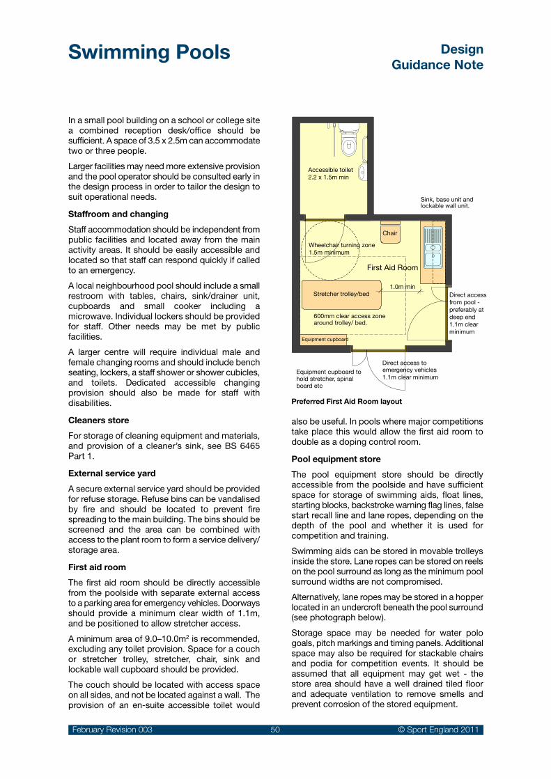
Swimming Pools DesignGuidance Note
February Revision 003 50 © Sport England 2011
In a small pool building on a school or college site a combined reception desk/office should be sufficient. A space of 3.5 x 2.5m can accommodate two or three people.
Larger facilities may need more extensive provision and the pool operator should be consulted early in the design process in order to tailor the design to suit operational needs.
Staffroom and changing
Staff accommodation should be independent from public facilities and located away from the main activity areas. It should be easily accessible and located so that staff can respond quickly if called to an emergency.
A local neighbourhood pool should include a small restroom with tables, chairs, sink/drainer unit, cupboards and small cooker including a microwave. Individual lockers should be provided for staff. Other needs may be met by public facilities.
A larger centre will require individual male and female changing rooms and should include bench seating, lockers, a staff shower or shower cubicles, and toilets. Dedicated accessible changing provision should also be made for staff with disabilities.
Cleaners store
For storage of cleaning equipment and materials, and provision of a cleaner’s sink, see BS 6465 Part 1.
External service yard
A secure external service yard should be provided for refuse storage. Refuse bins can be vandalised by fire and should be located to prevent fire spreading to the main building. The bins should be screened and the area can be combined with access to the plant room to form a service delivery/storage area.
First aid room
The first aid room should be directly accessible from the poolside with separate external access to a parking area for emergency vehicles. Doorways should provide a minimum clear width of 1.1m, and be positioned to allow stretcher access.
A minimum area of 9.0–10.0m2 is recommended, excluding any toilet provision. Space for a couch or stretcher trolley, stretcher, chair, sink and lockable wall cupboard should be provided.
The couch should be located with access space on all sides, and not be located against a wall. The provision of an en-suite accessible toilet would
also be useful. In pools where major competitions take place this would allow the first aid room to double as a doping control room.
Pool equipment store
The pool equipment store should be directly accessible from the poolside and have sufficient space for storage of swimming aids, float lines, starting blocks, backstroke warning flag lines, false start recall line and lane ropes, depending on the depth of the pool and whether it is used for competition and training.
Swimming aids can be stored in movable trolleys inside the store. Lane ropes can be stored on reels on the pool surround as long as the minimum pool surround widths are not compromised.
Alternatively, lane ropes may be stored in a hopper located in an undercroft beneath the pool surround (see photograph below).
Storage space may be needed for water polo goals, pitch markings and timing panels. Additional space may also be required for stackable chairs and podia for competition events. It should be assumed that all equipment may get wet - the store area should have a well drained tiled floor and adequate ventilation to remove smells and prevent corrosion of the stored equipment.
Stretcher trolley/bed
Equipment cupboard
Direct access toemergency vehicles1.1m clear minimum
Sink, base unit and lockable wall unit.
Chair
600mm clear access zone around trolley/ bed.
Accessible toilet2.2 x 1.5m min
Equipment cupboard to hold stretcher, spinal board etc
First Aid Room
Preferred First Aid room layout
Wheelchair turning zone1.5m minimum
1.0m minDirect access from pool - preferably at deep end 1.1m clear minimum
Preferred First Aid Room layout

Swimming Pools DesignGuidance Note
February Revision 003 51 © Sport England 2011
Other items such as inflatable play equipment can require a lot of space. Canoes can be hung from wall-mounted brackets in the pool store, or in the absence of adequate space, wall mounted near the pool. Transfer equipment and wheel chairs may also need to be accommodated.
Access doors should have a clear width of at least 1.1m and there should be sufficient space for easy access.
Pools with bulkheads will require additional storage for lane ropes of differing lengths, e.g. 50m pools with a bulkhead will require storage for 50m and 25m ropes. Additionally, 50m pools will require adequate storage for floating goals.
The overall size of the store will depend on the range of activities scheduled and a comprehensive schedule of equipment required.
The pool equipment store area can be estimated at an early stage of a project to be between 10 and 20% of the area of the pool water. Many of the items will be put away when wet and a tiled floor with drainage should be provided. In small pools the store may also be used to accommodate pool cleaning equipment.
A hose down point should be located in the store or inside a cupboard in the pool hall.
An alternative to storing lane ropes in a Pool Store – lane ropes can be stored in hoppers in the pool undercroft and accessed through stainless steel covers set into the pool end surround
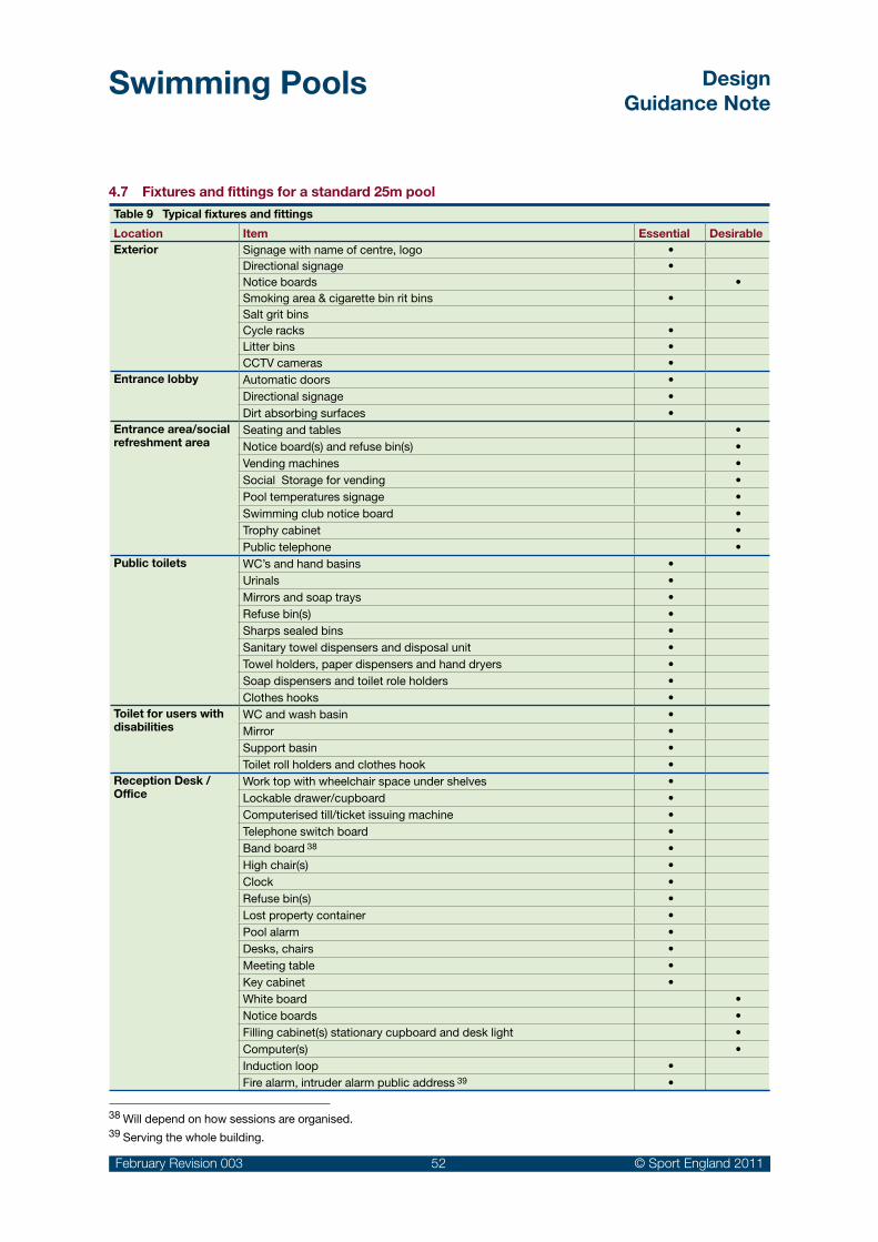
Swimming Pools DesignGuidance Note
February Revision 003 52 © Sport England 2011
Table 9 Typical fixtures and fittings
Location Item Essential Desirable Exterior Signage with name of centre, logo •
Directional signage •Notice boards •Smoking area & cigarette bin rit bins •Salt grit binsCycle racks •Litter bins •CCTV cameras •
Entrance lobby Automatic doors •Directional signage •Dirt absorbing surfaces •
Entrance area/social refreshment area
Seating and tables •Notice board(s) and refuse bin(s) •Vending machines •Social Storage for vending •Pool temperatures signage •Swimming club notice board •Trophy cabinet •Public telephone •
Public toilets WC’s and hand basins •Urinals •Mirrors and soap trays •Refuse bin(s) •Sharps sealed bins •Sanitary towel dispensers and disposal unit •Towel holders, paper dispensers and hand dryers •Soap dispensers and toilet role holders •Clothes hooks •
Toilet for users with disabilities
WC and wash basin •Mirror •Support basin •Toilet roll holders and clothes hook •
Reception Desk / Office
Work top with wheelchair space under shelves •Lockable drawer/cupboard •Computerised till/ticket issuing machine •Telephone switch board •Band board 38 •High chair(s) •Clock •Refuse bin(s) •Lost property container •Pool alarm •Desks, chairs •Meeting table •Key cabinet •White board •Notice boards •Filling cabinet(s) stationary cupboard and desk light •Computer(s) •Induction loop •Fire alarm, intruder alarm public address 39 •
4.7 Fixtures and fittings for a standard 25m pool
38 Will depend on how sessions are organised.39 Serving the whole building.

Swimming Pools DesignGuidance Note
February Revision 003 53 © Sport England 2011
40 For securing lane ropes, starting blocks, turning panels, backstroke warning flags and false start warning equipment.
Location Item Essential DesirableMale and female toilets and showers
WC’s •Urinals •Washbasins •Washbasins set within vanity units •Showers •Soap trays •Refuse bin(s) •Towel holders, paper dispensers and hand dryers •Soap dispensers •Toilet roll holders •Hat and coat hooks •Sanitary towel dispensers •Mobile hoist in changing rooms •
Vanity areas Hair dryers •Mirrors and shelves •Refuse bins •
Changing areas Bench seating for open plan and group roomsHat and coat hooks •Changing cubicles and clothes storage lockers •Real time clock •Cleaning materials •Wash down point & hosepipe •Speakers for PA •Nappy changing units •Refuse bin(s) •
Staff changing/toilets Lockers •Bench seating •Shower / toilet •
Staff rest room Table •Chairs •Work top, sink and drainer •Kettle, microwave, toaster, waste bin, clock •
Pool hall Pool cover •Sockets 40 •Lane ropes and storage wheels •Dividing (lane) ropes •Sweep hand timing clock •Life saving poles •Life saving resuscitation and other equipment •Life guards chair •Pool step ladders / grab rail •Water depth and safety signs •Automatic officiating system (for competition use) •White boards •Real time clock •Speakers for PA •Drowning alarms with repeaters at Reception and Plantroom •

Swimming Pools DesignGuidance Note
February Revision 003 54 © Sport England 2011
Location Item Essential DesirableFirst aid room Couch •
First aid cupboard •First aid equipment inc sealed sharps bins •Respirator spinal board and stretcher •Dressing trolley •Chair •Mirror •Screen •Sink with integral base unit •Refuse bin •Pin board •Accessible toilet inc WC & washbasin •
Pool equipment store Shelves •Teaching aids •Lane line reels •Pool equipment 41 •Portable seats 42 •Canoes 43 •Waterproof wheelchairs •Portable transfer equipment •Lockable cupboards •
Cleaners store Sink •Shelving for storing cleaning material •Brush for dragging pool •Long handled brush •‘Wet’ and ‘dry’ vacuum cleaner •Floor scrubber •Pool vacuum cleaner •Hosepipe •
Plant room(s) Work bench and tool rack •Speakers for PA •Real time clock •White boards •Pin board •
41 May include starting blocks, turning panels, backstroke warning flags and false start warning equipment and water polo equipment.42 If required for competitions.43 If required and not stored in pool hall.

Swimming Pools DesignGuidance Note
February Revision 003 55 © Sport England 2011
Spectator seating should be designed to meet:
Guide to Safety at Sports •Grounds - (The Green Guide)
BSEN 13200 Part 1•BS 9999: 2008 Code of •practice for fire safety in the design, management and use of buildings.
44 See page 9 of Section 2.0 ‘Early Considerations’.
Pool size Spectator seating
Competitor seating *
50m -10 lanes 500/600 300
50m - 8 lanes 350/400 300
50m - 6 lanes 200 200
25m - 8 lanes 250 min 250
25m - 6 lanes 150 min 180
Where pools are designed to stage Regional or National events on a regular basis the number of seats for spectators and/or swimmers may need to be increased.
* Poolside seating
4.8 Spectator & competitor provision
The provision in a swimming pool building generally falls into the following broad categories:
Informal viewing: •
Views from one area to another, for user understanding of the layout and visual interest. It can also help in the operation of the building and allow a degree of supervision. Viewing can be from both external and internal circulation routes or from supporting areas such as the café or reception area.
Formal viewing:•
Viewing from fixed seating, often in stepped tiers along the long side of the main pool, usually provided where there will be a significant element of competitive swimming.
Pool surrounds:•
Seating along the pool surround is usually limited to use for swimmers or for competitors during events. Subject to location, operational issues and accessibility, the surrounds may be used as occasional temporary spectator seating for small galas although careful consideration should be given to the control of foot traffic on the pool surround.
Spectator seating can add significantly to the cost of a project. Advice from the ASA Facilities Department should be sought in establishing justification 44 and appropriate capacity.
Table 10 Guide to seating capacity if swimming competitions are held on a regular basis
Cost increases are likely due to a range of issues including additional floor area and volume, impact upon sanitary, heating and ventilation systems,
additional access requirements, fire escapes, parking and storage within the building.
Sight line geometry
It is important that spectators have a good view of the whole pool water, the pool ends and score board(s). The design of the sight line geometry needs to be carefully considered.
The ‘Green Guide’ states the maximum angle of seating rake should not exceed 34˚.
The ‘C value’ or distance of the sight line above the head of the person in the row in front and the ‘focus point’ are indicated in the diagram on page 56. The minimum C value should be 0.090m, but 0.120m is preferred.
The ability to achieve an adequate ‘C value’ can become progressively more difficult with each tier of seating. The worst case location should therefore be checked.
Generally, the higher the spectator seating, the further the seating will need to be from the focus point. The space below the seating might be useable for changing rooms or pool storage depending on the layout of a particular project and the height the seating is installed at. The provision of vomitories may be necessary to allow height clearance at access points to the pool.
Ideally, sight lines should relate to a focus point at the edge of the pool, particularly in 10 lane pools where all lanes may be used (See red on the following example).

Swimming Pools DesignGuidance Note
February Revision 003 56 © Sport England 2011
C
R
D
N
T
T = Seating Row depth
N = Riser height
R = Vertical distance from focus point to eye
D = Horizontal distance from focus point to eye
C = ‘C’ Value
Focus point at water level - preferred at pool edge (Red) or if impossible at centre of �rst swimming lane (Blue)
However, where this is not possible the sight lines should be taken from a focus point located at the centre of the first lane at water level (blue lines on the following example).
Riser heights and seating row depths will generally be a function of multiples of 0.28m minimum goings and 0.19m maximum risers in order to comply with BS 9999:2008 and the ‘Green Guide’ for radial gangways.
Accessibility
Accessibility for wheelchair users needs to be considered early in the design. In very large facilities wheelchair accessibility should be distributed across the seating levels 45. However for smaller facilities, accessibility may only be practical at pool side and/or the uppermost level of the seating.
The position and height of wheelchair spaces should also take into account the likelihood of spectators standing in the rows in front, as shown in the above diagram.
Seating types
The type of seating will depend on use and scale of the seating provision. Competitor pool side
seating is commonly a ceramic tiled ledge, possibly heated for bather comfort.
Spectator seating for small pools may be formed from a simple continuous laminate slat usually without a back rest, fixed to each concrete tier.
Intermediate spectator seating will generally be as for small pools, but be provided with a fixed backrest, or individual moulded plastic seat squabs with integral backrest, directly fixed to each concrete tier.
Larger pools will generally include individual spectator seats consisting of a coated metal support frame, fixed plastic back rest and tilting seat squab, to allow easy access between rows. All framing materials should resist a pool hall environment.
Conflict with the need for privacy
There is a potential conflict between open views into the pool water areas and the need for privacy for certain sensitive user groups. The addition of easily operated blinds or other screening devices should be considered for all the glazing to the pool hall and or the learner pool.
Environmental conditions
See the building services Section 5.0 (page 57) for environmental conditions that should be created for formal spectator seating when located within a pool hall enclosure.
Example of spectator seating design
45 Refer to ‘Accessible Sports Facilities’ design guidance note available from the Sport England website.

Swimming Pools DesignGuidance Note
February Revision 003 57 © Sport England 2011
5.0 Servicing the building
A safe, comfortable and attractive internal environment is essential in order to attract and sustain high levels of use. Good conditions are also required for the lifeguards, teachers and spectators as well as achieving a reasonable life expectancy from the building 46.
The engineering challenge in achieving the functional requirements in a sustainable manner is substantial 47:
Large volumes of swimming pool water needs •to be kept warm and continually treated to deal with the pollution from bathers.
Air temperature, moisture content and air •quality in the pool hall need to be carefully controlled.
Issues include the containment and control of •a potentially corrosive atmosphere in the appropriate areas, internal acoustic conditions, and noise breakout to surrounding areas.
It is estimated 48 that the building services installation can account for between 35 and 50% of the capital costs of a modern pool. The operational sustainability is therefore critical.
The full pattern of use, operation and maintenance regimes of the swimming pool should be allowed for within the services design. The operator’s requirements should be obtained at an early stage in the design process.
Energy implications
Swimming pools use high levels of energy. It is imperative that the building footprint is minimised at the design stage and internal volumes carefully modulated to give an appropriate feeling of space and airiness. The building fabric should also be well insulated and effectively sealed from the outside environment and any adjoining building elements.
Energy efficiency
At the initial planning stage a range of energy saving measures and the overall energy environmental sustainability must be considered 49. In deciding the most appropriate strategy, whole life cost rather than only capital costs should be assessed.
The plant requirements can be considered in the following groups:
Incoming services: Water, •electricity, gas and meters
Pool water treatment •system: Water filter(s) circulation pumps and pipework, chemical dosing equipments and backwash disposal
Foul water disposal /•drainage
Heating system: To heat •the pool water, areas of the building and domestic water supply including storage vessels and pressurisation systems
Energy / resource recovery •equipment: Heat exchangers, CHP plant, water re-use
Air-handling plant: Heating •and conditioning the pool hall air and associated spaces
Electrical distribution •equipment
Water storage•Movable floor and / or •bulkhead systems.
46 The HSE book Managing Health and Safety in Swimming Pools is a key reference.
47 CIBSE Guide G Public health engineering: Swimming pools.
48 Sports Council Guidance Note Swimming Pool - Building Services Nov 1994.
49 The UK national planning system has recently been amended to make sustainability its underlying principle (PPS1).
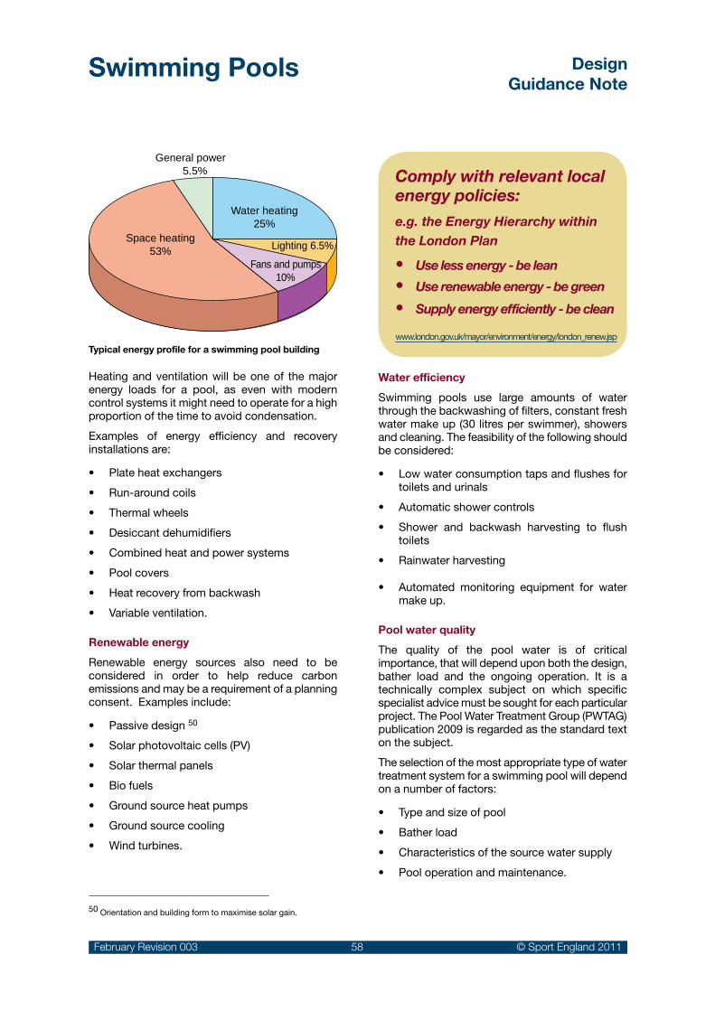
Swimming Pools DesignGuidance Note
February Revision 003 58 © Sport England 2011
Heating and ventilation will be one of the major energy loads for a pool, as even with modern control systems it might need to operate for a high proportion of the time to avoid condensation.
Examples of energy efficiency and recovery installations are:
Plate heat exchangers •
Run-around coils•
Thermal wheels•
Desiccant dehumidifiers •
Combined heat and power systems•
Pool covers•
Heat recovery from backwash•
Variable ventilation.•
Renewable energy
Renewable energy sources also need to be considered in order to help reduce carbon emissions and may be a requirement of a planning consent. Examples include:
Passive design • 50
Solar photovoltaic cells (PV)•
Solar thermal panels•
Bio fuels•
Ground source heat pumps•
Ground source cooling•
Wind turbines.•
Water efficiency
Swimming pools use large amounts of water through the backwashing of filters, constant fresh water make up (30 litres per swimmer), showers and cleaning. The feasibility of the following should be considered:
Low water consumption taps and flushes for •toilets and urinals
Automatic shower controls•
Shower and backwash harvesting to flush •toilets
Rainwater harvesting•
Automated monitoring equipment for water •make up.
Pool water quality
The quality of the pool water is of critical importance, that will depend upon both the design, bather load and the ongoing operation. It is a technically complex subject on which specific specialist advice must be sought for each particular project. The Pool Water Treatment Group (PWTAG) publication 2009 is regarded as the standard text on the subject.
The selection of the most appropriate type of water treatment system for a swimming pool will depend on a number of factors:
Type and size of pool•
Bather load•
Characteristics of the source water supply•
Pool operation and maintenance.•
General power 5.5%
Space heating53%
Water heating25%
Fans and pumps10%
Lighting 6.5%
Comply with relevant local energy policies:e.g. the Energy Hierarchy within the London Plan
Use less energy - be lean•Use renewable energy - be green •Supply energy efficiently - be clean•
www.london.gov.uk/mayor/environment/energy/london_renew.jsp
50 Orientation and building form to maximise solar gain.
Typical energy profile for a swimming pool building

Swimming Pools DesignGuidance Note
February Revision 003 59 © Sport England 2011
Pool type/ bather load
Conventional disinfection
UV* O3*
Conventional/low 6Conventional/medium 6 6Leisure/high 6 6*Residual disinfection is required in addition to prevent cross infection in the pool.
*O3 = Ozone
Disinfection
A ‘conventional’ chlorine system has generally been considered to give an appropriate balance of capital costs, water and air quality, bather comfort, ease of control, maintenance and economy of operation. Sodium hypochlorite or calcium hypochlorite are commonly used to maintain a ‘free chlorine level’ in the pool water to deal with the pollution from bathers or other sources. Automatic control and dosing systems are regarded as essential to maintain safety, and give obvious staffing and operational benefits.
However, water purification based on Ultra-Violet (UV) and to a lesser extent Ozone (O3) equipment is commonly added into modern public pool installations. This involves additional equipment within the plant room areas, to treat the circulating water and make subsequent disinfection easier. The benefits of such systems are:
Reduction in chlorine levels in the pool.•
Improved water quality – particularly where •high bather load is expected.
Improved air quality in the pool hall – through •reduction in airborne chloramines associated with red eyes, sore throats aggravation of asthma and bronchitis, particularly beneficial to asthma sufferers, pool staff and long term pool users.
However these systems can add significantly to the capital and running costs of providing a conventional chemical only system. Both systems can also require increased expertise from the operator.
There are particular safety and technical issues with all water treatment systems but as a general guide the use of purification systems are as follows:
Chemical dosing
Chlorine is used in the pool water to kill bacteria and prevent cross infections between bathers. The most common chlorine donors are:
Sodium Hypochlorite ( NaOCI)•
Calcium Hypochlorite ( Ca (OCI)2)•
These individually produce ‘free chlorine’ a chlorine compound for disinfection, and ‘combined chlorine’ when free chlorine is combined with pollutants - the cause of the typical chlorine smell in swimming pools.
It is necessary to control the acidity (pH) balance of the treated water. For example, diluted hydrochloric acid (HCI) is added when sodium hypochlorite is used.
Using other chemical treatments should be discussed in detail with the water treatment engineer. In particular the use of Sodium BiSulphate (NaHSO4) should be avoided due to the risk of sulphate attack on cementitious grouts, renders and concrete. See the PWTAG publications for more detail.
Pool water chemicals should always be dosed and monitored by automatic equipment. Additional manual testing of samples of water from the pool should be undertaken regularly, at least twice a day as an additional check on the system.
Water softness
The use of calcium hypochlorite is often preferred in areas of ‘soft water’ since it is a calcium hardness donor to the pool. This will minimise the effects of soft water on cementitious materials used in the pool construction.
See the PWTAG 2009 publication for more more details and the appropriate design standards.
Ozone contact vessel and de-ozonising
Table 11

Swimming Pools DesignGuidance Note
February Revision 003 60 © Sport England 2011
Filtration systems
An effective filtration system is required to maintain the clarity of the swimming pool water. For public pools sand filters are most commonly used. In order to maintain their effectiveness these will need to be backwashed regularly. This is achieved by reversing the flow through the sand beds and then discharging the backwash water to a foul drain.
The discharge to the drains is classified as trade effluent and the consent may place restrictions on the timing, volume and/or flow rate discharge per day. Backwash tanks to hold the back wash water may be required to allow a controlled discharge to the foul drainage system.
The overall hydraulics of the system, the rating of pumps and the position of inlet and outlet grills in the pool tank need to be carefully designed to ensure contaminants are effectively removed from the water. Deck level systems are most effective in removing contaminants from the water surface.
To assist the filtration process chemicals known as flocculants are automatically added to the water prior to it passing through the filters. Poly aluminium chloride is most commonly used and it forms a ‘floc’ that helps trap fine particles, microbes and pollutants in the water.
UV filtration system
Turnover rates
The time for the total volume of pool water to circulate through the treatment plant and return to the pool is known as the turnover rate. The period depends on the shape size and use of the pool and should be considered early in the design process as part of the water treatment system performance requirements.
See the PWTAG 2009 publication for more details and the appropriate design standards
Typical filter installation
Pool Type Depth (Metres)
Pool Turnover Rate (Hours)
Diving N/A 4 - 8
Swimming N/A 2.5 – 3
Leisure <0.5m 0.5
0.5 to 1.0 0.5 - 1
1.0 to 1.5 1 to 1.5
>1.5 2 to 2.5
Table 12 Recommended turnover rates
The risk of contamination of the pool water can be minimised through:
Careful design and •location of showers and toilets
Good house keeping•
Bather education. •
(See showers and changing room layout in Section 4.5)

Swimming Pools DesignGuidance Note
February Revision 003 61 © Sport England 2011
Extract Fan
Heat Exchanger
Main air handling unit
Frost coil
Fresh airsupply
Exhaust
Heatherbattery
vel'
Temperature & humidity
Monitoring sensor
29 degC
Pool 28 degC
Of�ce
Changing rooms
Toilets
Circulation pumps
DisinfectionPool calori�er
Time switch controlled damper
Time switch controlled valve
Filters
Boiler
Radiators* & pipe coils
* Some radiators have thermostatic valves. All coils havethermostatic valves with remote sensors.
Extractfan
Exhaust
CO2
Temperature & humidity
CO2
Temperature & humidity
Pool 28 degC
Environmental sustainability needs to be considered in the building services design, with opportunities for heat recovery, grey water harvesting and low energy systems.
Ventilation system
Filtration systemHeating system
Water puri�cation (i.e. uv or ozone)
Time switch controlled valve
Hotwatersupply
WP
WP
Schematic services diagram for a typical small pool
Sodium hypochlorite bulk and day tanks
Water temperature
Over the years there has been a steady trend to increase water temperatures to increase customer satisfaction. This is demonstrated in the latest update of the PWTAG publication (2009)51 that quotes maximum temperatures for swimming pools that are 1-2 degrees higher than the previous edition of 1999. However the energy usage implications should be carefully considered and it should be noted that the PWTAG document also advises that operators may run their pool satisfactorily at temperatures 1-2 degrees lower.
Recommended maximum pool water temperatures
PWTAG 1999
PWTAG 2009
Competitive swimming and diving, fitness training 27°C 28°C
Recreational, adult teaching, conventional main pool 28°C 29°C
Leisure pools 29°C 30°C
Children’s swimming As above 31°C
Babies, young children, disabled 30°C 32°C
Hydrotherapy 35°C
Spa pools 40°C
Higher water temperatures may be attractive to recreational swimmers, disability groups and children, but be less suitable for fitness swimming or competition. Higher water temperatures may also have an adverse impact on the water treatment and environmental control systems. See notes on the PWTAG web site on the problems associated with operators running pools at higher temperatures.
Table 13
51 ‘Swimming pool water treatment and quality standards’ Pool Water Treatment Advisory Group (PWTAG).

Swimming Pools DesignGuidance Note
February Revision 003 62 © Sport England 2011
Air temperatures and humidity
Pool hall
High temperature and humidity are required in the pool hall to maintain comfortable conditions for bathers. Air temperatures are usually kept at one degree above the pool water temperature and relative humidity and air velocity values as follows:
Air temperature: approx 30°C •(assuming 29°C water temperature)
Relative humidity: 60% ± 10%•
Air velocity: Approx. 0.1m/s in the • occupied areas of the pool hall
Min fresh air supply: 8-10 air changes/hour•
There should be even distribution and extraction of warm air from the pool hall so there are no draughts on the pool surrounds or in the shallow end where people may be standing up.
The above conditions assume that the mean radiant temperature is approximately equal to or slightly higher than the air temperature. The atmospheric conditions within an enclosed space are never homogeneous and vary with time and location. They are particularly influenced by bather activity.
Care should be taken that moisture and smells from the pool hall cannot pass to adjoining areas. Effective moisture vapour barriers are required and gaps should be sealed to avoid potential damage to the building elements, particularly where services and ducts pass through walls. A negative pressure difference between the pool hall and adjoining areas such as changing areas can be used to help contain the pool environment.
See PWTAG 2009 for the importance of the ventilation system in removing air born disinfectant by-products and contaminants from the pool hall and ensuring an adequate distribution of fresh air.
Spectator area
Spectators in adjacent seating and viewing areas will require a lower temperature created by an increased fresh air supply as follows:
Air temperature: approx 25°C• 52
Relative humidity: 60% ± 10%•
Air velocity: approx 0.3m/s•
Min fresh air supply: 10 air changes/hour•
Additional comfort cooling systems may also be considered for spectators, but care should be taken to avoid cooler air dropping into bather areas and causing discomfort.
Changing and clothes storage areas
The airflow should be evenly distributed and designed to remove smells, particularly in changing areas and toilet areas. There should be no draughts caused by airflow. In order to provide comfortable conditions as people change and move back into the public areas the following conditions should be provided:
Air temperature: approx 24-25º C•
Min fresh air supply: 10 air changes/hour•
This is often arranged as a separate system from that for the main pool hall. Some additional comfort cooling within the system could be beneficial in vanity areas where people would in their normal clothing.
Baby changing accommodation should have separate rates of ventilation.
Electrical services
Special care should be taken with electrical services in view of the damp warm and corrosive atmosphere 53. Mains voltage must not be accessible within the pool hall.
Light fittings
See Section 4.3 general design issues for artificial lighting in the pool hall.
There are particular issues with underwater lighting:
Size/type needs to suit the pool to be •illuminated
Reliability•
Expected lamp life/replacement cost•
Ease of re-lamping•
Water safety – no fitting should exceed 20V •operating current – need for transformers located relatively close to each fitting.
Where moveable floors are used, the underwater light fittings will need to be flush with the pool wall.
Some underwater light fittings may also suffer from high temperatures at the glass lens, and in
52 20°C is recommended for ancillary areas. Managing Health and Safety in Swimming Pools.
53 IEE guide and Electricity at work regulation1989.

Swimming Pools DesignGuidance Note
February Revision 003 63 © Sport England 2011
order to avoid the risk of bather injury, the operational temperature of the surface of the glass should never become so hot as to be uncomfortable or dangerous.
Sizes of plant rooms
Plant rooms should be sized to give good access to the equipment that they house and allow for operation, maintenance, replacement and deliveries.
Typically the pool water treatment plant room should be between 15-30%
54 of the water area that it serves.
An economical solution is to locate the air-handling plant at high level providing there is adequate access. A ‘rule of thumb’ to calculate the overall area required is to allow approximately 15% of the pool building area.
Plant room spaces
The location, size and distribution of the plant within the building needs to be considered early in the design process along with the operation and maintenance factors.
The plant room spaces should:
Allow the plant and equipment to be installed, •commissioned, operated and maintained safely and efficiently.
Allow for service access and removal/•replacement of all individual elements including bulky items such as filters.
Minimise service runs, with water treatment •plant located close to the deep end of the pool tank.
Locate pool water circulation pumps at the •same level as the bottom of the deepest water so that they are continually flooded.
Allow for the delivery and storage of chemicals •in a separate, ventilated area. Include appropriate safety arrangements such as bund walls for chemical storage tanks and dosing equipment and emergency drencher and eye wash facilities.
Ensure adequate ventilation rates to all plant •room areas. If ozone treatment is used, provide an automatic ozone detection alarm system and consider the need for similar systems for chlorine and carbon dioxide.
Ensure adequate floor drainage in the plant •room and provide a hosepipe point.
Provide an accessible balance tank to •accommodate water displaced by bathers (for deck level pools only). Access should be via lateral access ways from the plant room rather than manholes in the pool surround floor.
Provide holding tanks if required for the main •drainage system to deal with the quantity of filter backwashing water (can be separate from plant room).
Allow space for new technology such as housings •for underwater camera control panels.
Provide adequate space for a workbench, •desk and chair, tools, maintenance manuals and so on.
Ensure flues, air intakes, ventilation and extract •louvers/cowls are positioned away from public and residential areas.
Ensure safe access to all plant/equipment •requiring regular inspection.
Allow for control equipment and underwater •pool windows associated with computer assisted underwater pool supervision.
Plant rooms should be connected to all •emergency alarms.
Access to plant rooms
Access to the plant room should be available both internally via a controlled access point and externally via delivery entrance. All doors leading to the plant room must have secure locking mechanisms fitted to prevent access by untrained staff and members of the public.
If an external service yard is provided, the external access should incorporate the provision of a steel shutter door system. The door should be fitted with a high security locking system and be connected to the centre’s security alarm. The ideal opening size is 3.0m wide by 2.5m high. There should also be an additional side door for external access to the plant room to reduce wear and tear on the steel shutter and the probability of it being left open during a period of frequent use.
Doors in the plant room should be of a heavy duty nature and have a minimum opening width of 1.0m (1.5 m preferred).
Air distribution systems in the pool hall
There is a marked move away from supplying air through overhead ducted systems to the use of ducts incorporated at low level into the pool tank design. These systems either sit adjacent to the
54 PWTAG / Sports Council Guidance Note : Swimming pools Building Services.

Swimming Pools DesignGuidance Note
February Revision 003 64 © Sport England 2011
pool water overflow system or are set at low level around the perimeter of the pool hall. If located under glazed curtain walling they have the additional benefit of reducing the condensation that can form on the windows.
The low level systems do have drawbacks – poorly designed systems can become flooded if the pool water spills over the pool deck surround or from ground water. If no drainage system is incorporated into the air duct then, at worst extensive damage to the air handling plant ensues, at best the flood water is very difficult to remove.
Over head ducting is still specified in some pool designs and as with direct lighting units it can prove difficult to avoid positioning directly over water and maintenance becomes very problematic.
The ductwork fixings must be carefully selected as there have been several cases of ducting sections falling from height due to corrosion and subsequent failure of the fixings studs etc. Regular inspection of all ventilation ductwork and fixing must take place. This requires suitable access.

Swimming Pools DesignGuidance Note
February Revision 003 65 © Sport England 2011
6.0 Constructing the building
The need to pay particular attention to the detailed construction specification for swimming pools can scarcely be overstated. The building must withstand a warm, humid and aggressive internal environment and external temperatures expected in the winter season. This can be a highly technical, complicated and demanding subject, requiring the services of specialist consultants. Key factors include:
Heavy wear and tear and possible abuse •during use.
Avoidance of interstitial and surface •condensation that can lead to corrosion/rot and failure of various elements - particularly those concealed within the structure.
Ease of maintenance to ensure a clean and •hygienic environment that eliminates dust, dirt and water traps.
The creation of safe conditions for users.•
The following notes are intended to illustrate the range of potential problem areas and point to the need to ensure experienced professional expertise is available in all areas of the project team and that due account is taken of current research and recommendations.
Types of pool tank design
The pool tank and the pool surround need to be designed as water retaining structures. There are two main types:
Concrete pool tanks
These would normally be constructed from shuttered in-situ reinforced concrete to BS 8007. They can be formed with or without a screed /render and normally have a ceramic tile finish.
Waterproofing additives can be used to reduce the risk of leakage. The tank structure should be thoroughly tested for water tightness, through a full depth tank test before finishes are applied. Any faults should be remedied after allowing the pool tank to dry out thoroughly, and before tiling or lining work is undertaken. Any repair is more effective from the wet side.
Pre-cast concrete panels should generally be avoided due to problems of guaranteeing water tightness at the joints. Permanent shuttering should also be avoided due to risks of deterioration if leakage does occur over the life of the pool tank or problems identifying any leakage path for repair.
Structural movement joints in the pool tank should be avoided where possible. Joints between the tank and the pool surround should also be minimised where possible. If joints are unavoidable, these must have an effective proprietary water bar system suitable for their application.
Pool surrounds should be designed to the same standard as the pool tank, and provision made to prevent lateral water travel to other areas.
Other concrete pool construction forms include sprayed concrete (gunnite) and concrete blockwork formwork filled with reinforced concrete. These forms are primarily associated with private and hotel pools, and there are considerations in respect of their use in larger pools that will require very careful attention. Expert independent advice should be sought before considering these forms of pool construction.
The use of tanking membranes in the pool surrounds, as an alternative to water retaining concrete should generally be avoided. However if tanking is unavoidable great care must be taken in the selection, detailing and testing of the membrane. The risk of damage due to thermal shock when the pool is emptied or filled with water and heated is a critical issue. This must be taken into account and integrated into the design, construction and operation of the building as follows:
Activity Rate 55
Max fill/empty rate 0.03m/hour (0.75m/day)
Max heating rate 0.25°C/hour (6°C/day)
Table 14
Materials – should be selected with regard to their environmental sustainability, whilst also ensuring durability and lifecycle qualities:
Recyclable content•
BRE green guide rating•
Environmental profile.•
55 BS5385: Part 4: 2009 Wall and floor tiling – Part 4: Design and installation of ceramic and mosaic tiling in special conditions – Code of practice.

Swimming Pools DesignGuidance Note
February Revision 003 66 © Sport England 2011
Stainless steel pool tanks
Prefabricated sectional stainless steel tank structures are becoming more common, although in the UK these are still an emergent market. They are supported on a concrete slab and are either site welded to form a complete tank structure or are bolted together. A welded reinforced plastic liner may also be used for the walls and/or floor of the tank.
Advantages of the stainless steel pool:
Quicker to assemble and install (but will require •an extensive period for design and offsite fabrication).
Elimination of issues associated with a •conventional concrete pool tank.
Finished quality and dimensional tolerances of •the tank can be more closely controlled.
Tank under construction in stainless steel panels with an integrated overflow and raised end
Issues to be carefully considered as part of the system selection and design process include:
The need for independent structures for the •steel pool tank support framework and pool surround retaining walls, allowing periodic checks for potential leaks and degradation.
Selection of the support structure and panel •materials and their fixings to avoid or minimise the risk of corrosion.
Establish that the pool system will last the •intended design life of the building. A cost in use appraisal for the proposed life of the building is recommended.
Provision of a watertight joint at the junction •between the steel tank and the pool surround needs careful consideration. The pool perimeter details are critical: a tanked pool surround may be required, and the interface of the pool and surround needs careful detailing in order to avoid leakage. Where pool liners are used, the pool wall panel liner should be fully bonded to the metal panel.
Fixed pool equipment: As discussed in section •4.4 the pool surrounds require a number of fixing points for temporary equipment associated with the various elements of the swimming progamme. Refer to section 6.0 for details.
The length of manufacturer’s guarantees for •the polymer liner and the risk of mechanical damage.

Swimming Pools DesignGuidance Note
February Revision 003 67 © Sport England 2011
Pool tank constructions
A comparison of the essential key differences (assuming other factors can be treated as equal)
Concrete Stainless Steel
Structural Option 1:
Monolithic design for whole of tank and •pool surrounds when constructed from insitu water retaining concrete to BS 8007/ BS EN 1992 Part 3 gives a highly stable structure
Option 1:
Stainless steel side walls incorporating •structural back framing fixed to a reinforced concrete floor
Option 2: 56
Gunnite sprayed reinforced concrete•
Reinforced concrete block work with •waterproof renders /coatings
An Integral transfer channel is the most common option
Fixtures and fittings need to be integrated into the tank design
Option 2:
Polished stainless steel side walls and •floors incorporating structural back framing and welded seams
Stainless steel wall panels are generally available up to 3m depth only – deeper pools will need a composite wall of concrete (lower) and stainless steel (upper)
An integral stainless steel transfer channel can be part of these systems
Some fixtures and fitting can be integrated into an integrated transfer channel
Junction with pool surrounds and floor structure need special care
Waterproofing Inherent within well constructed insitu •reinforced concrete pools meeting BS 8007/ BS EN 1992 Part 3
Can be augmented by waterproof liner •and/or render
Option 1
Factory bonded PVC faced galvanised •or stainless steel wall panels and loose PVC floor liner with all seams thermally welded
Option 2
Bare polished stainless steel wall and •floor panels with welded panel joints
Option 3
Structure as option 1 with loose fitted •PVC water proof pool liner with thermally welded seams
Finishes Option 1
Fully ceramic tiles on render backing is •the preferred finish
Option 1
PVC factory applied finish to wall panels •and loose PVC liner sheet to floor
Option 2
Specialist finish renders and paint •finishes have been used where long term durability is not so important
Option 2
Ceramic tile option to upper wall sections •subject to design and stiffening
Option 3
Loose PVC liner•
56 Gunnite and reinforced concrete construction are more commonly used for private /hotel/fitness centre pools and are unlikely to achieve the long term life of an in-situ RC pool.

Swimming Pools DesignGuidance Note
February Revision 003 68 © Sport England 2011
Concrete Stainless Steel
Robustness Robust - minimal risk of damage from •vandalism or pool hall activities.
Durable •
Stable construction•
Workmanship is critical to waterproofing •and long term life of the pool
PVC lining is liable to mechanical •damage from sharp objects. e.g. puncture resulting in leakage.
Potential movement issues at the •junctions with loose linings and more rigid wall/floor and wall/ surround
Workmanship is critical to •waterproofing and long term life of the pool
Service life Proven long service life. Examples c 100 years +
Periodic replacement of liners required •( c 10 years )
Oldest examples c 40 years•
Maintenance Minimal long term maintenance of pool tank structure. Re-grouting of ceramic tiles may be required c 20 year intervals. Life of finishes will depend upon quality of materials, maintenance of pool water quality, wave action and chemicals utilized
Regular inspection and quick repair of •PVC liner damage required
Annual inspection of stainless steel •structure to check for pitting/corrosion
Construction Long construction period for building the •concrete shell
Wet trade for pool finishes require an •extensive period for application and curing
Lack of a long term warranty. •(Depending on type of contract the latent defects period will be 6/12 years and the patent defects period will be12 months)
Long overall construction program•
Lengthy off site design and •prefabrication time requires early placement of the contract
Short installation period•
Maximum warranty period 15 years•
Reductions in programme time are •possible compared to a concrete pool. (Likely to be more appropriate for temporary and portable facilities)
Quality control Resolution of severe defects and leakage •can be complex requiring potential drainage of pool and resulting in extended closure
Dimensional control dependant on •quality of workmanship on site
Resolution of severe defects and •leakage can be complex requiring potential drainage of pool and resulting in extended closure
Dimensional control achieved through •factory prefabrication and site control
Costs
Tank construction Normally used as benchmark Cheaper in terms of capital costs and short term expenditure
Other associated costs in the construction process
Dependant on the under-croft and basements plant room configurations and the contractors allowances for preliminaries.
Dependant on the under-croft and basements plant room configurations and the contractors allowances for preliminaries
Shorter contract prelims are likely•
Periodic lining replacement and closedown costs (over a 60 years period)
Over a period of 60 years periodic close down of the pool would be expected for repairs to tiles and grouting. Possibility of retiling in refurbishment terms from 25 years
Over a period of 60 years periodic close down of the pool would be expected for replace the lining from 10 years
Other maintenance costs
Mechanical damage to lining would require urgent repair

Swimming Pools DesignGuidance Note
February Revision 003 69 © Sport England 2011
Pool edge details
The pool edge detail can be formed with proprietary solid, pre-cast ceramic units, or cast as part of the concrete pool edge profile, where the deck level channel is set back away from the pool edge. In both cases the channels are covered with a slotted plastic grille. The following are important factors regarding finishes to a pool:
An appropriate surface treatment to concrete •pool tanks is required to provide a key for applied finishes. This is usually achieved through mechanical keying the concrete surface to expose the coarse aggregate.
Compatibility of the tiling specification with the •tile adhesive and grouting.
Soft water, aggressive chemicals, rapidly •moving water or heavy wear may require tiling to receive epoxy based adhesives and/or grouts in lieu of cementitious based ones.
However for cost, application and programme reasons, the use of epoxy grouts should be minimised.
Waterproof membranes should generally not •be used between pool tiling and a concrete pool structure, as these can be the cause of subsequent failure of the finishes if there is any shocking of the tank during emptying or heating of the pool. The pool tank should be designed to be waterproof.
The noise of the circulating water continuously •falling into the deck level channel can be distracting. In order to minimise the impact of water flow, the pool side of the deck level channel should be set at an angle so that the water runs down the channel side face rather than tumbles into the channel. See Section B-B overleaf.
Typical low voltage recessed underwater light fitting
654m
m
Pool underwaterlight �tting should beselected on lamp lifeease of re-lamping andcost in addition to anyperformance criteria.
Deck level channel.
Conduit cast into concrete betweenpool light and deck box mounted 0.3mabove water level.
Pool underwaterlight �tting set intoniche cast into poolwall with thickened concrete behind.
Pool lights in pools �tted with movable �oors will need to be �ush with the tiled wall.
Max gradient 1:10Pool Surround Foul Drain
Pool Suround Max gradient 1:40
Note:
Refer to page 80 for further information regarding drainage of pool surrounds.

Swimming Pools DesignGuidance Note
February Revision 003 70 © Sport England 2011
B
B
B
B
AA
AA
525mm min
300
Section A - A - Alternative example of raised end with integrated ceramic filtration ‘scum’ channel providing a finger grip at water level
Separate pool surround foul drainage
Section A - A - Example of builders work raised end excludingfiltration channel and with finger grip provided at top
Examples of pool edge details.
Note: The provision of permament raised ends should be limited to pools where extensive competitive use is an essential requirement. Lifeguard supervision will also need to take account of any additional risks the provision of raised ends may present to bathers .
Note: For inexperienced swimmers the channel may present a hazard during tumble turns. For poor swimmers and older people however, particularly those with limited shoulder mobility taking part in length swimming, the channel is of considerable help and gives con�dence to swimmers.
Note: rake to front face of channel to reduce water generated noise.
B
B
CC
CC
B
B
Note: The Weisbaden pool edge detail is unlikely to be suitable for larger pools due to the limited capacity of the channel. Advice should be obtained from the services consultant before selecting this detail.
Example plan of a general purpose swimming pool showing deck level edge channel provided to the perimeter of the pool tank. For competition use removable turning boards and starting platform can be used
Example plan of a competition pool with permanent raised pool ends with deck level edge channels provided along the sides of the pool tank
Note: Rake to front face of channel to reduce water generated noise. Twin channels built into pool surround - one to take pool water return to �ltration the other to provide independent drainage of the pool surround to prevent poluted water entering the pool.
Section B - B - Alternative example of deck level edge channel (’Weisbaden’ ceramic channel).
Section B - B - Example of deck level twin edge channel (Builders work)
Section C - C - Example of deck level pool end with twin edge channel and removable starting platform with integral turning boards (if required - bolted to pool surround)
300
Starting platform
Separate pool surround foul drainage
870
B
B
B
B
AA
AA
525mm min
300
Section A - A - Alternative example of raised end with integrated ceramic filtration ‘scum’ channel providing a finger grip at water level
Separate pool surround foul drainage
Section A - A - Example of builders work raised end excludingfiltration channel and with finger grip provided at top
Examples of pool edge details.
Note: The provision of permament raised ends should be limited to pools where extensive competitive use is an essential requirement. Lifeguard supervision will also need to take account of any additional risks the provision of raised ends may present to bathers .
Note: For inexperienced swimmers the channel may present a hazard during tumble turns. For poor swimmers and older people however, particularly those with limited shoulder mobility taking part in length swimming, the channel is of considerable help and gives con�dence to swimmers.
Note: rake to front face of channel to reduce water generated noise.
B
B
CC
CC
B
B
Note: The Weisbaden pool edge detail is unlikely to be suitable for larger pools due to the limited capacity of the channel. Advice should be obtained from the services consultant before selecting this detail.
Example plan of a general purpose swimming pool showing deck level edge channel provided to the perimeter of the pool tank. For competition use removable turning boards and starting platform can be used
Example plan of a competition pool with permanent raised pool ends with deck level edge channels provided along the sides of the pool tank
Note: Rake to front face of channel to reduce water generated noise. Twin channels built into pool surround - one to take pool water return to �ltration the other to provide independent drainage of the pool surround to prevent poluted water entering the pool.
Section B - B - Alternative example of deck level edge channel (’Weisbaden’ ceramic channel).
Section B - B - Example of deck level twin edge channel (Builders work)
Section C - C - Example of deck level pool end with twin edge channel and removable starting platform with integral turning boards (if required - bolted to pool surround)
300
Starting platform
Separate pool surround foul drainage
870
Examples of pool edge details

Swimming Pools DesignGuidance Note
February Revision 003 71 © Sport England 2011
Finish tolerances
Floors generally < 0.005m *
Floors laid to falls < 0.003m *
Finished tile level of leading edge of deck level pool channel consistent datum level
0.000m *
* The greatest distance between the straightedge and the tile surface measuring over a distance of 3m.
Table 15
Points to consider:
Permanent raised ends •help to prevent swimmers misjudging the end of the pool and avoid the need for turning boards for competitions
A drainage channel is still •required to drain the pool surround behind the raised ends if the surrounds fall towards the pool edge
A hand hold is required•
Fixings for lane lines, •starting platforms, turn boards (if no raised ends), touch panels and automatic timing equipment.
Finishes to wet areas
Tiling to all wet areas should be laid to a fall. A gradient of 1:40 is generally adopted, but should not be steeper than 1:35 or flatter than 1:55 for safety and proper drainage.
A consistent datum level around the deck level channels is particularly important to ensure a consistent flow of water over the weir and the proper functioning of the deck water circulation system. Structural movement joints must be coordinated with tile joints, and sealants must be selected on their suitability for use in a pool.
Stress relieving joints in the tiling must also be carefully considered. BS 5385 Part 4 recommends stress relief joints at all changes of direction and every 6m where tile grout joints are less than 5mm wide. However, for the purposes of good practice stress relief joints should be considered in any pool regardless of joint size.
The selection of slip resistant tiles can be complex in the UK. The majority of ceramic tiles are tested for slip resistance under the German DIN Standards, DIN 51097 (bare foot) and DIN 51130 (shot foot) 57 both of which are excellent for establishing a tile’s inherent slip performance. However these are tests undertaken in a laboratory, and it is not possible to assess tile performance once installed.
In the UK the HSE pendulum and micro-roughness tests 58 are increasingly used to establish insitu slip performance. This is mainly due to the HSE slip resistance test being portable and is being used in legal injury compensation cases.
Slip resistance tests can be influenced by a number of factors, including surface profile, extent of tile joints in addition to any inherent slip resistant properties of the tile. Also, slip resistance can degenerate due to poor care during construction or poor cleaning techniques during use.
It may be necessary for the tiles to be additionally tested at specification, post-installation and during use to enable comparison in actual performance.
The primary benefit of the HSE tests are that they can be undertaken to test a particular tile insitu, to enable a comparison of the tile’s performance and assist in identifying the potential cause of any slip problem as supplied, installed or maintained.
Generally, bare foot only trafficked areas such as the pool surround should have the highest grade of slip resistance. These would include pool surrounds, flume towers, showers, shallow water areas (less than 1.35m) where the buoyancy is low and anywhere where barefoot users might be tempted to run. In other areas where barefoot and shod foot traffic is shared the ability to easily clean and maintain the tiles also needs to be considered.
Note: The slip resistance requirements of tiling in the pool tank is specified in BSEN 15288-1:2008.
57 HSE Technical Information Sheet ‘Assessing the Slip Resistance of Flooring.
58 See Appendix 2 and BSEN 15288: Part 1: 2008 Swimming Pools: Safety requirements for design.

Swimming Pools DesignGuidance Note
February Revision 003 72 © Sport England 2011
When selecting tiles avoid selecting on the basis of marginal passes in tests, as construction and use will inevitably allow some degradation in performance.
A mid tone colour is usually considered most practical for keeping a clean appearance. Avoid white and dark colours on pool surrounds or any heavily trafficked areas as these can show stains and are difficult to clean.
Structural frame
The structural spans involved in a swimming pool design usually involve a framed structure. Steel or timber laminated beams and columns are commonly used. However, load bearing masonry and steel or timber beams can be a feasible solution on small projects.
The protection of the structure from corrosion and/or rot is of the utmost importance, particularly as the material’s strength and stability can also be impaired. For example, some adhesives in laminated timber can be adversely affected by the pool atmosphere and steelwork can be badly corroded when concealed within the wall construction.
Steel work must be protected with an elaborate proprietary paint system that involves specified thicknesses of zinc rich paints that are often epoxy or polyurethane based. All protective coatings should be carefully discussed with the specialist coating company and be based upon intended use, expected environment, exposure and a life to first maintenance, normally not less than 10 – 15 years.
Roof structures will need to support:
Suspended services such as ventilation ducts •and light fittings
Equipment such as safety harnesses in diving •pools.
Tile manufacturers should be asked to provide slip resistance test data in accordance with HSE guidance in addition to DIN standard test data.
Roof enclosure
Critical factors are the avoidance of interstitial and surface condensation and material corrosion. Key design checks should assess condensation risk, vapour resistance gradient, thermal insulation gradient, and ventilation.
The roof construction/ceiling finish should be designed to:
Provide high levels of insulation and to prevent •condensation
Be resistant to the pool environment•
Provide sound absorption•
Have no effect on the colour of the pool water•
Withstand ball impact if the pool is used for •water polo
Provide a good surface reflector for the spread •of light.
A number of proprietary systems are available that are a composite of an outer weathering sheet, insulation, a vapour barrier and aluminium inner lining sheet. They can eliminate internal voids and use the self finish lining layer as a vapour barrier. However, other factors such as the need for fixings for an acoustic underlining need to be considered.
Roof-lights should be of the double glazed diffusing type, not more than 25% (approximately) of the total roof area.
Where suspended ceilings are considered, it is important that the space is not subject to a risk of condensation. This can be done by designing the roof structure as a ‘warm roof’. Care must be taken to avoid piercing vapour barriers with fixings. For ceiling hangers or suspended services protected fixing systems are available to hold the roof to the structure.
External walls
The principles of design to avoid cold bridging and avoiding interstitial condensation in the roof apply equally to the walls.
External walls should be constructed to:
Provide high levels of insulation•
Withstand damage from vandalism•
Provide an attractive, durable, low maintenance •finish
Allow for structural movement as required by •the structural engineer
Be resistant to the pool environment.•

Swimming Pools DesignGuidance Note
February Revision 003 73 © Sport England 2011
Masonry and metal cladding systems as external materials are very common. Increasingly common is timber cladding, which should be designed in accordance with the TRADA publication ‘External Timber Cladding’.
The Building Regulations New AD Part L requires higher levels of insulation and special consideration should be given to thermal bridging, vapour barriers and dew point control due to enhanced risk of condensation.
Internal skins of external walls should preferably be of masonry or concrete block work (with or without applied finishes).
Lightweight structural framed systems are being used for some conventional construction projects, but due to the aggressive pool environment (including condensation and corrosion risks) specialist advice must be sought before considering as this may impact upon the building’s expected life.
Gypsum walling products (e.g. plasterboard) should be avoided.
Glazing
Glazing will need to be double or triple glazed. Large areas of glass can cause cold radiation which can be reduced by local ventilation or electrically heated glass (expensive). High thermal performance glass may be a requirement to meet current Building Regulations 59, particularly for large glazed elements.
Where areas of thermally insulated glazing are used, particularly if including solar control glass, thermal shading coefficient checks should be made.
Glazing adjacent to the pool surrounds must be able to resist body impact and if the pool is to accommodate water polo - ball impact. Refer to BS6262 and BS 6399: Part 1. The risk of injury if glass is broken should be given careful consideration in all barefoot areas. In addition, glass when immersed can be very difficult to see, therefore glass should be laminated. Consider toughening glass prior to lamination for maximum safety.
For resistance against rot, glazed assemblies are commonly aluminium proprietary framed units with a powder coated finish and integral thermal break.
59 Building Regulations Approved Document Part L.
Where the glazing is formed using structural glazing e.g. planar type systems, great care must be taken in respect of material use – stainless steel glass support fittings in particular need consideration due to corrosion risks.
If timber windows are to be used, select from a proprietary range with known performance in pools. Important considerations include:
Timber species & grade•
Method of rot protection•
Finish•
Exposure rating•
Structural requirements•
Fire requirements•
Life to first maintenance.•
Roof lights – There are a wide range of rooflight materials that are suited for use in a pool environment. The primary considerations for their selection should be:
Structural requirements – span and impact •upon the primary roof structure – particularly vaults or stressed skin systems (e.g. inflated ETFE – Ethyl-tetra-fluoro-ethylene) where lateral tension or compressive loads can be transferred.
Resistance to corrosion – selection of materials •and finishes.
Condensation through framework – need for •a thermally broken system, or through the glazing – avoid glazing with separate skin multiple units where condensation can become trapped between the glazed skins.
Curtain walling – in addition to the requirements for glazing above, large areas of curtain walling will require a secondary support structure, normally of steel hollow section or possibly laminated timber, attached back to main structural frame members. Steel secondary framework will need similar corrosion protection as the main structure and dissimilar materials must be isolated to minimize risk of galvanic action resulting in corrosion of metals in contact with each other.
Glass balustrades are a common feature in swimming pool facilities that provide spectator viewing to the pool area. However, the glass must be designed to BS6262 and BS 6399: Part 1. Structural supports must be designed to obviate the risk of corrosion and bare stainless steel should be avoided (see page 76).

Swimming Pools DesignGuidance Note
February Revision 003 74 © Sport England 2011
Internal walls
The internal construction / finish should:
Withstand body impact and ball impact if the •pool is used for water polo.
Prevent water penetration at low level from •regular hosing down of pool surrounds.
Allow for structural movement as required by •the structural engineer.
Resist staining and absorption of body fats.•
Have no effect on the colour of the pool •water.
Provide sound absorption above 2m from pool •surround level.
Be capable of supporting loads, including •services, pool cover, bench seating, including the loading of person(s) standing on them.
Avoid use of ‘stud’ partitions – particularly •those with gypsum wallboard products. Where studwork is unavoidable ensure all framework is of galvanised steel, further coated in severe locations – not timber and select wall boards suitable for constant wetting without deformation, absorption or degradation. Avoid use where fittings are to be fixed to the wall.
Provide horizontal dpc’s at top of skirting level •to prevent rising damp into the wall.
Movable floors and bulkheads
The movable floor/bulkhead design, construction and installation should:
Comply with the recommendations of BS EN •13451; Part 11 and the HSE publication HSG 179 - Managing Health & Safety in Swimming Pools’ section Physical Environment.
Allow for easy movement of the floor/bulkhead.•
Not interfere with or compromise in any way •the circulation of the water in the pool.
Bulkheads that are part of a deck level surround should have a black line to denote the edge.
Bulkheads that are used to separate pools of different depths or are used for access by swimming officials during an event should have portable stainless steel hand or barrier rails and a handhold at water level.
The floor/bulkhead manufacturer should provide detailed information regarding installation requirements and accuracy of the pool tank necessary for their proper operation.
Fixed pool equipment
For competition use a pool will require a range of fittings and equipment. (See also Section 4.7):
Automatic officiating system (timing) including •timing pads, electronic interface to special starting platforms, connections for starting with both audible and visual signals and computer interface for scoring
Electronic scoring board(s), timing clocks•
Starting platforms and (for pools without •permanent raised ends) turning boards
Lane ropes•
False start rope posts•
Water polo goals•
Back stroke warning flags and posts•
Diving boards (spring boards and platforms).•
The officiating equipment and score boards can be temporary or permanent systems depending upon use. For regular use a system including permanent wiring and ducts should be considered. Specialist advice should be sought at an early stage to identify builder’s work needed to be incorporated. The selected system should meet ASA/FINA requirements.
Diving boards will need to comply with the ASA/FINA requirements. Springboards are generally required of an approved type and manufacturer. (See also section 4.4).
The remainder of the equipment noted above is normally mirror polished grade 316 stainless steel and re-movable, but would require stainless steel permanent sockets to be fitted into the pool and pool surrounds. Examples of these are shown on the following diagram. These are normally core drilled into the finished floor/wall and set in epoxide grout rather than cast-in, in order to achieve accuracy of placement. However the pool structure will need to be designed to accommodate the fittings without undermining any water proofing and the sockets may in some cases need to resist pull-out loads.
BS EN 13451 Parts 1 to 11 inclusive covers the safety requirements for items of all equipment used in a swimming pool. Refer to Appendix 2 for a complete list of the various parts.

Swimming Pools DesignGuidance Note
February Revision 003 75 © Sport England 2011
Fixed Pool Equipment
150
min
38mm diameterstainless steelcylindrical socket
Stainless steel cap seals socket when equipment removed
150
min
48mm polished stainless steel removable tubular rail
Platform secured by stainless steel bolt screwed into socket
Stainless steel boltseals socket whenequipment removed
75 m
in
150
Support bracket bolted into socket
150
Lane rope attaches to removable stainless steel eye bolt �xedinto socket
Stainless steel socket withintegral coverplate resinanchored intopocket cast inor core drilledinto concrete
Stainless steel tubedrops into socket
‘E’ type socket - turning boards
‘D’ type socket - False start/backstroke warning poles
‘B’ type socket - Pool entry step handrails
Stainless steel socketresin anchored intopocket cast in or coredrilled into concrete
‘A’ type socket - Lane Ropes(Deck Level Detail)
150
Lane rope attaches to stainless steeleye bolt �xedinto socket
Stainless steel socketresin anchored intopocket cast in or coredrilled into concrete
Stainless steel socket resinanchored intopocket cast inor core drilledinto concrete
5m
5m
10m
5m
Lane ropes at 2m centres0.5m 0.5m
Back stroke warning �ag line
Back stroke warning �ag line
False start recall line
C/E
B
D
D
D
A
Location of equipment
Start ing platforms
Pool equipment locations and fixing details for a 25m x 6 lane swimming pool
Stainless steel socket resinanchored intopocket cast inor core drilledinto concrete
‘C’ type socket - Starting platform
‘A’ type socket - Lane Ropes(Freeboard Detail)

Swimming Pools DesignGuidance Note
February Revision 003 76 © Sport England 2011
Stainless steel in the pool hall environment
Stainless steel is not corrosion proof and needs special consideration for swimming pool applications. There has been a marked increase in premature failures of the material in recent years that has been linked to the way swimming pools are being constructed and used. This includes:
Higher pool water operating temperatures at •(30oC+) and thermal gain through glazing that creates air temperatures that are considerably higher.
Pool features such as flumes and water sprays •increase levels of water vapour and chloramine pollutants in the atmosphere.
Increased use of stainless steel in highly •stressed structures – particularly under tension.
Inadequate control of ventilation and moisture •content.
Increased use of cold formed stainless steel •components – or mixture of cold and hot formed materials in components such as bolts.
These conditions cause degradation of the passivating layer stainless steel normally produces to protect itself from corrosion. If left unchecked pitting and crevice corrosion quickly occur. This can lead to stress corrosion cracking (SCC) and premature failure of components.
This can be particularly serious if stainless steel components are used for structural support – such as roof trusses and ventilation ductwork.
If stainless steel is essential in structural situations avoid details in which key components are under high stress 60. Avoid bare stainless steel components and consider a protective coating.
Operators should instigate a regular inspection routine and put in place maintenance practices to make good any visible corrosion before it becomes serious.
Only use bare stainless •steel in situations within the pool splash zone and where it can be easily and regularly cleaned and inspected.
Consider grade of •stainless steel and finish to minimise maintenance and risk of corrosion.
Consult with the Nickel •Development Institute (NiDI) and the British Stainless Steel Association (BSSA) regarding ideal grade for each application.
In other situations, •stainless steel should be given a factory applied protection e.g. powder/epoxy coated.
60 NiDi document 12 010 ‘Stainless Steel in Swimming Pool Buildings’.

Swimming Pools DesignGuidance Note
February Revision 003 77 © Sport England 2011
Corrosion of stainless steel balustrading and control panel exposed to pool atmosphere
Corrosion to stainless steel fittings
Doors and frames
External doors need to be well insulated and avoid cold bridges. Robust timber doors treated with preservative have been commonly used, but thermally insulated steel or aluminium powder coated doors are preferred. The door specification must withstand severe temperature variations, damp conditions and will need adequate corrosion protection.
Internal door construction should be solid-core, rot protected, water and boil proof grade doors with plastic laminate facing and lipped on all sides suitable for a swimming pool environment. Door frames should also be heavily protected particularly the end grain near to or in contact with the floor.
However in very wet locations or where the operator is likely to wash/hose down surfaces timber doors should be avoided in favour of more robust doors and frames such as proprietary glass reinforced polyester (GRP) encapsulated non-timber cored door sets.
Hinges and screw fixings must be corrosion- resistant, and if stainless steel, should be powder coated.
Acoustics
The acoustic environment of the swimming pool hall should be considered from the earliest stage of the design. There are potential conflicts between the acoustic absorption qualities of finishes and the resilience required to withstand the exacting atmospheric conditions and heavy wear and tear.
Large areas of hard impervious finishes, glazing and the water’s surface are all efficient reflectors of sound. The roof deck provides the largest potential area for sound absorption although it may be broken up by service ducts, fittings or roof-lights. The control of reverberant noise requires relatively large areas of sound absorbing material.
Many pools are built with a proprietary profiled metal roof deck with a degree of perforation. In some instances, proprietary sound-absorbent baffles or panels are used. In all instances moisture penetration must be avoided.
Reverberation times:
The overall hall construction should provide control of the reverberation time (RT) to between 1.5 and 2.0 seconds at 500Hz 61. It is essential that advice is sought from an acoustic engineer in respect of the acoustic performance of a pool hall, not just for the comfort of all swimmers, coaches, lifeguards and spectators, but also for the ability to hear audible fire alarms, public address and evacuation calls. This is vitally important in swimming pool halls
61 BSEN 15288: Part 1: 2008 recommendations.

Swimming Pools DesignGuidance Note
February Revision 003 78 © Sport England 2011
with large internal volumes, particularly where formal spectator seating is included. During swimming competitions and galas a very high background noise level can be expected.
Ambient noise levels/ sound insulation:
Control of ambient noise levels in the pool hall from the building services and external noise is also an important part of creating an acceptable environment and the building fabric should include appropriate sound insulation. Noise from building services (heating, ventilation and electrical) and external break-in noise should be limited to NR40 in terms of dBL Aeq30 62.
Breakout noise:
In some situations the sound that maybe emitted from the swimming pool may also be an issue that will have implications for the overall building structure and envelope.
Pools on school sites are required under the building regulations to comply with DfES Building Bulletin 93: 2003 and this is also recommended for all pools in which swimming instruction and coaching will take place.
62 See ‘Accessible Sports Facilities’ available from the Sport England website for issues for people with hearing difficulties.

Swimming Pools DesignGuidance Note
February Revision 003 79 © Sport England 2011
7.0 Operating the building
Key operational /design issues
The following issues are often overlooked in new projects and should be the subject of early discussion with operators.
Reception as the hub of both normal and emergency communications
• Pool alarms, security, fire etc (all with different sounds)
• Publicaddressandradiosystem (audible in all areas)
• Backgroundmusicmustbelinked to a fire alarm override
• Allturnstilesneedtobelinkedto the fire alarm system to allow an unrestricted flow in an emergency or power failure
• Firealarmindicationpanel
• Fireman’sswitch
Zones of supervisions for staff
• Closingoffareasnotinuse
• Staffalarmpoints
• Extentofvisualsupervision
Safe demarcation of deep water
BS EN 15288 Part 1 requires a 100mm wide demarcation line in a conspicuous colour across the pool tank floor at the 1.2m depth point to aid lifeguard supervision
Maintenance of lights at high level
Scaffold towers or ‘cherry pickers’ often require the use of stabilising out riggers or anchorage points to cope with the gradient of the floor on pool surrounds
Delivery of bulk chemicals
The pool chemical supplier needs to be contacted in the early stages of the design to ensure that the safe delivery of bulk chemicals is considered including:• Accesswidth
• Pipecouplingdetails
• Washdownandhosepoints
• Additionalsafetyfeatures
Key Maintenance Issues
Swimming pools are generally subjected to continuous heavy and prolonged use having to cope with high levels of pollution and aggressive environmental conditions that can significantly increase wear and tear and affect the life of the facilities.
The ability to keep the building looking attractive, fresh and clean for its life will depend upon:
The standard of the design of the facility.•
The quality and suitability of materials selected •in the construction and finishes.
Attainment of high quality workmanship during •construction.
The occupancy of the facility within the range •identified at the design stage. If a pool attracts a higher number of users than expected or designed for, this can lead to accelerated wear and tear requiring more regular maintenance and repair.
Regular servicing and correct operation of all •environmental systems.
Regular and appropriate cleaning and •maintenance of the building necessary for the level of use and to include making good damage or faults at early stages so that they do not contribute to long term degradation of finishes.
Training of staff in cleaning and maintenance •duties and appropriate work schedules and supervision.
All of the above points are important, but regardless of the quality of the design or construction, if the building is not maintained at levels appropriate to its use, the life of the building can be rapidly degraded.
During the design stages it is important that the operator is consulted to ensure that the design does not require unreasonable levels of maintenance once in use. Equally, on completion of any project, clear cleaning and maintenance strategies should be established to advise the operator on how best to maintain the building and obtain the best use from it.
There are a number of important issues that should be particularly considered by pool operators. These include:
Entrance Control
Entry mats/floor surfaces at the main building entrances should be kept effective and regularly cleaned to minimise the influx of shoe borne debris etc.
During periods of extended inclement weather the operator may need to initiate additional measures to improve removal of debris from shoes prior to entry to the changing rooms. Increased cleaning measures may also be needed.
Table 16
Inappropriate levels of maintenance can rapidly shorten the life expectancy of the building.

Swimming Pools DesignGuidance Note
February Revision 003 80 © Sport England 2011
Ceramic Tiling
Ceramic tile slip resistance can be substantially degraded by the build up of debris, pollutants (including dead skin, body fats, bacteria and lime scale).
The operator’s cleaning and maintenance regime must take into account the recommendations of the Tiling Association literature ‘The Cleaning of Ceramic Tiles’ 63 in maintaining the tiles.
Showers
The operator should effectively promote a pre-swim shower regime for bathers to minimise body pollutants being carried into the pool hall and the pool itself.
Use of shower gels and shampoos should be limited to enclosed shower cubicles and not be used in open showers, particularly those forming part of a circulation route.
Washing Down
Wet tiled floor areas may be washed down with a hose after the surface chemical cleaning is complete. Appropriate lockable hose points and drainage channels or gullies should be provided. Alternatively, it is common practice in small and medium sized pools to use pool water to wash down surrounds and provide mild disinfection. However jet or pressure washers must not be used as these will have deleterious effects upon tile grout and other surrounding materials.
Washing down should be used in conjunction with a regular cleaning regime using appropriate cleaning materials to remove surface pollutants and limescale, as noted for ceramic tiling above.
Wash down water should not be sprayed indiscriminately, as this can have detrimental effects upon fixtures and fittings including doors, door frames, lockers etc.
Drainage Channels
Pool surrounds: Drainage should be independent of the deck •level pool water recirculation channel 64.
Careful selection of suitable gratings over the •drainage channels must be specified to maintain slip resistance.
Changing rooms: Gratings should be lifted at the end of each day and the channels should be hosed down to flush away hair / body fat build up. Use of bactericide recommended for use within pool environments should be used regularly to further improve hygiene.
Inadequate falls on floors and badly located drainage gullies can mean that water is left to pond on the floor and increase the risk of accidents and clothing accidentally dropped into standing water.
Stainless Steel
Stainless steel will need to be regularly cleaned and the following should be taken into account
All bare stainless steel elements around the •pool should be washed down on a daily basis with clean water.
The stainless steel should be wiped over with •a clean cloth on a monthly basis.
The recommendations of the British Stainless •Steel Association (BSSA) and Nickel Development Institute (NiDI) should be followed.
Carbon steel brushes of wire wool, or any •abrasives (including abrasive cleaning compounds) should not be used as this will damage the surface and increase surface staining.
Any chemical cleaning products must be •suitable for use on stainless steel.
Designed environmental conditions within the •pool hall must be maintained.
Fall
To sewer
To sewer
Water treatment system and back to pool
Water treatment system and back to pool
Fall
Example pool channel drainage to meet BSEN 15288 Part 1 2008
63 The Tile Association http://www.tiles.org.uk
64 BSEN 15288-1: 2008 requires the pool surround to be designed to avoid contamination of the pool water by water flowing on to the floor.

Swimming Pools DesignGuidance Note
February Revision 003 81 © Sport England 2011
Appendix 1: Related organisations
Amateur Swimming Association (ASA)http://www.swimming.org/asa/
The ASA is the national governing body in England for swimming, diving, water polo, open water and synchronised swimming and provides extensive training programmes for all those involved in teaching swimming.
Association for Physical Education (AFPE)http://www.afpe.org.uk
In 2006 Physical Education Association of the United Kingdom (PEAUK) joined with The British Association of Advisers and Lecturers in Physical Education (BAALPE) to become the Association for Physical Education becoming the UK's Physical Education subject association.
British Swimming Coaches Association (BSCA)http://www.gbswimcoaches.co.uk/
The BSCA is the representative organisation for swimming coaches which gives employment, legal and educational support.
Health and Safety Executive (HSE)http://www.hse.gov.uk
The HSE and the Health and Safety Commission (HSC) are responsible for regulating almost all the risks to health and safety arising from work activity in the UK.
Institute of Sport, Parks and Leisure (ISPAL)http://www.ispal.org.uk
ISPAL (formerly ILAM) represents every aspect of leisure, culture and recreation management and is committed to the improvement of management standards.
Institute of Sport and Recreation Management (ISRM)http://www.isrm.co.uk
ISRM aims to lead, develop and promote professionalism in the management of sport and recreation and provide opportunities to encourage participation in sport and other recreational activities.
National curriculum swimming and water safetyhttp://curriculum.qcda.gov.uk
This site provides guidance and ideas for teachers in planning and teaching swimming activities and water safety as part of the PE national curriculum.
Royal Life Saving Society (RLS)http://www.lifesavers.org.uk
The Royal Life Saving Society is the leading drowning prevention organisation in the UK and is the national governing body for Life Saving and Life Guarding in the UK.
Royal Society for the prevention of Accidents (RoSPA)http://www.rospa.co.uk
The Royal Society for the Prevention of Accidents is a registered charity to promote safety and the prevention of accidents including on (or near) water.
Sport Englandhttp://www.sportengland.org
Sport England is responsible for providing the strategic lead for sport in England. It develops the framework for the country’s sporting infrastructure and distributes lottery funding to where it will deliver most value.
Sports Coach UKhttp://www.sportscoachuk.org
Sports Coach UK is dedicated to guiding the development and implementation of a coaching system, for all coaches at every level in the UK.
Sport + Recreation Alliancehttp://www.sportandrecreation.org.uk/
The Sport + Recreation Alliance is the umbrella body for 270 sport and recreation organisations. They have published a charter for PE and School Sport and a guide leaflet ‘Safety at the Water Margins’ – both available on the website.

Swimming Pools DesignGuidance Note
February Revision 003 82 © Sport England 2011
Appendix 2: Standards and legislation
Legislation:
Operational Issues / Health & Safety
The Construction (Design and Management) Regulations 2007 places duties on designers to illuminate hazards and risk during design, and to advise on those risks that remain. The term ‘designer’ is used broadly and may include a client, contractor and anyone involved in the preparation and modification of a design or the instruction of others 65.
The HSE/SE document HSG179 – Managing Health and Safety in Swimming Pools set out the health and safety legislation with which all pool operators must comply. Operators have a general duty to ensure, as far as practicable that the public and employees are not exposed to health and safety risks, and make suitable and sufficient risk assessments. It contains practical advice and guidance to help pool operators meet their responsibilities based on best practice agreed across the industry.
Standards for equipment used in swimming pools
BS EN 13451 which covers the safety requirements for items of equipment used in a swimming pool. Published originally in 2001 the standard includes the following:
Part 1 General safety requirements and test methods.
Part 2 Additional specific requirements and test methods for ladders, step ladders and handle bends.
Part 3 Additional specific requirements and test methods for equipment for water treatment purposes.
Part 4 Additional specific safety requirements for test methods for starting platforms.
Part 5 Additional safety requirements and test methods for lane lines.
Part 6 Additional safety requirements and test methods for turning boards.
Part 7 Additional specific safety requirements and test methods for water polo goals.
Part 8 Additional specific safety requirements and test methods for leisure water features.
Part 9 Safety signs.
Part 10 Additional specific safety requirements and test methods for diving platforms, diving spring boards and associated equipment.
Part 11 Additional specific safety requirements and test methods for movable pool floors and movable bulkheads.
New European standards:
Swimming pools
The Swimming Pools standard BS EN 15288: 2008 was published by the British Standard Institute in January 2009 as part of the long process to unify standards across Europe in the interest of free trade. The standard is in two parts:
Part 1: Safety requirements for design
Part 2: Safety requirements for operation
The standard applies to all new pools and refurbishments within three types:
Type 1 Public pools where the water-related activities are the main business (e.g. communal pools).
Type 2 Public Pools which are an additional service to the main business (e.g. hotel pools).
Type 3 All other public pools that are not Type 1 or 2.
The standard does not apply to Private pools designated solely for the owner’s/proprietor’s/operator’s family and guests including use connected with renting houses for family use.
The standard will not apply to:
Pools used for medical or therapeutic •purposes
Private pools used solely by owners, family •and friends.
It has limited application to segregated areas of rivers, lakes and the sea.
It is important to note that Part 1 of the document is not in line with some established minimum safety standards in the UK. The National Foreword to the document advises users to ‘consider closely’ the contents of a number of existing UK documents
65 http:/www.opsi.gov.uk/si/si2007/uksi_20070320_en_1
http:/www.hse.gov.uk/pubns/books/l144.htm

Swimming Pools DesignGuidance Note
February Revision 003 83 © Sport England 2011
with the ‘intention of maintaining current levels of swimming pool safety’:
The Handbook of Sport and Recreational •Building Design (Sports Council)
The Swimming Pool Water Guide (Pool Water •Treatment Advisory Group – PWTAG)
HSG 179 Managing Health and Safety in •Swimming Pools (Health and Safety Executive)
PAS 39 Management of public swimming •pools – water treatment systems, water treatment plant and heating and ventilation systems – Code of Practice
PAS 65 Management of public swimming •pools – General management – Code of Practice.
Part 1 of the document identifies design features for public swimming pools that are required to create a safe environment and the introduction
stresses the following general principles:
Safety of swimming pools starts with design.•
Everyone in the design process should be •familiar with ‘specific sources of information’ and ‘recommendations’.
Everyone in the design process should be •aware of operational implications. Safety design can reduce risks of accidents and operational costs.
An experienced facility manager should be •part of the project team.
Other areas the standard represents are increases over existing UK standards.
These are noted in the text of this guidance note and can be summarised as:
Depth of water requiring slip resistant tiles has •increased from 1.2m to 1.35m
Width of surround where there are exit points •from the pool

Swimming Pools DesignGuidance Note
February Revision 003 84 © Sport England 2011
Pool side drainage to waste drainage•
Conspicuous line on pool floor at 1.2m depth•
Minimum dimensions of separation barriers •between pools
Dimensions of rest ledges, and steps in •pools.
Equipotential net•
Lightning protection•
Requirement for pool covers•
Dimensions of first aid rooms•
Requirements of pool side control points•
Requirements for water treatment chemicals•
Size and location of signage of pool depth.•
Waterslides
Waterslide design, installation and operation should take into account the following standards:
‘Waterslides – A code of practice for their safe •Operation’ - Institute of Sport and Recreation Management (ISRM)
BS EN 1069: Part 1: 2000 Water slides of 2m •height and more - Part 1: Safety requirements and test methods
BS EN 1069: Part 2: 2000 Water slides of 2m •height and more - Part 1: Instructions
BS EN ISO 13857:2008 Safety of Machinery •- Safety distances to prevent danger zones being reached by upper and lower limbs
BS EN 1176: Part 1: 2008 Playground •Equipment - General Safety Requirements and Test Methods
BS EN 22768: Part 1: 1993 General Tolerances •- Tolerances for Linear and angular dimensions without individual tolerance indications.

Swimming Pools DesignGuidance Note
February Revision 003 85 © Sport England 2011
Appendix 3: Changing room calculation example
Standard Method 66 (See section 4.5)
Pool Water AreaPool 1 Main pool 25 x 13m 325.00 m2
Pool 2 Learner pool 13 x 7m 91.00 m2
416.00 m2 - Total water area to be served by the changing rooms
Step 1 Steady state conditiona Any one time capacity = water area ÷ 3 138.66 3 3m2/ person is recommended for calculating
maximum numbers for un-programmed swimming. However any use of a pool should be subject to a full risk assessment.
HSE publication HSG179 ‘Managing Health & Safety in Swimming Pools. Para 203
b Assumed time in pool hall (hours) 0.75 3 To be discussed with operator. Longer times of say 1 hour are likely in leisure pools
c Number changing per hour = a ÷ b 184.88
d Number of places required = c ÷ 4.5 41.09 3 4.5 is calculated by assuming an average time for changing of approx 13 minutes and dividing it into 1 hour
Step 2 Call-out groupse Number of groups (Operators policy) 5
f Number in call out groups = a ÷ e 27.73
g Discount call out group by 20% = f x 80% 22.18 Allowing for swimmers who do not stay in pool for the full call out session
h Add 50% of d 20.54 Allowing for new people coming into changing rooms
i Number of spaces required = g + h 42.72
Step 3 Spaces out of usej Add 10% for spaces out of use 4.27
k Total number of spaces required = 47
Step 4 Decide on the mix of changing space types
Option 1 See typical plan (Example 1) on page 46
Mixed sex area / Village changing
l Single cubicles required k ÷ 3 15.67 16 people
m Double cubicles required k ÷ 3 15.67 32 people
n Four person family / disabled 4 See Sport England Design Guidance Note ‘Accessible Sports Facilities’
o Equality provision: unisex changing room 1 See Sport England Design Guidance Note ‘Accessible Sports Facilities’
p Flexibility to give privacy for sensitive groups See typical plan page 29
66 From Handbook of Sport and Recreation Building Design. Volume 3: Swimming Pools and Ice Rinks.
Table 17
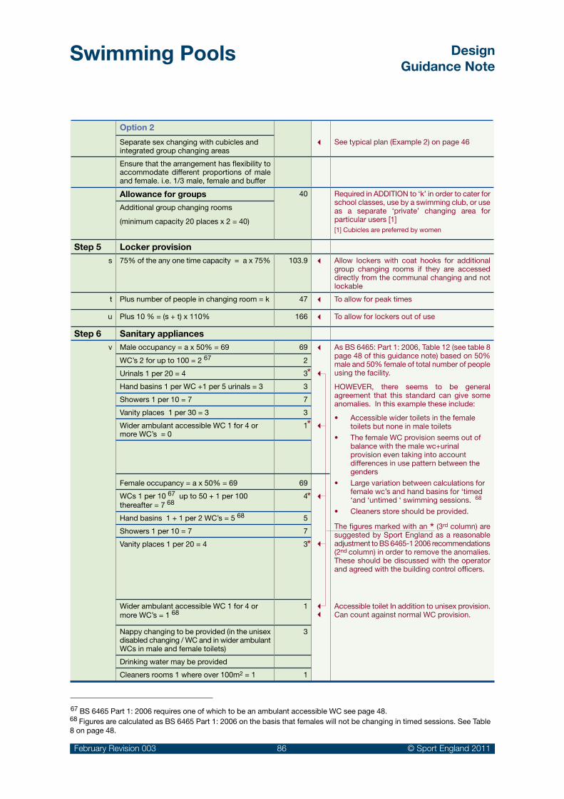
Swimming Pools DesignGuidance Note
February Revision 003 86 © Sport England 2011
Option 2
3 See typical plan (Example 2) on page 46Separate sex changing with cubicles and integrated group changing areas
Ensure that the arrangement has flexibility to accommodate different proportions of male and female. i.e. 1/3 male, female and buffer
Allowance for groups 40 Required in ADDITION to ‘k’ in order to cater for school classes, use by a swimming club, or use as a separate ‘private’ changing area for particular users [1][1] Cubicles are preferred by women
Additional group changing rooms
(minimum capacity 20 places x 2 = 40)
Step 5 Locker provisions 75% of the any one time capacity = a x 75% 103.9 3 Allow lockers with coat hooks for additional
group changing rooms if they are accessed directly from the communal changing and not lockable
t Plus number of people in changing room = k 47 3 To allow for peak times
u Plus 10 % = (s + t) x 110% 166 3 To allow for lockers out of use
Step 6 Sanitary appliancesv Male occupancy = a x 50% = 69 69 3
3
3
3
3
33
As BS 6465: Part 1: 2006, Table 12 (see table 8 page 48 of this guidance note) based on 50% male and 50% female of total number of people using the facility.
HOWEVER, there seems to be general agreement that this standard can give some anomalies. In this example these include:
• Accessiblewidertoiletsinthefemaletoilets but none in male toilets
• ThefemaleWCprovisionseemsoutofbalance with the male wc+urinal provision even taking into account differences in use pattern between the genders
• Largevariationbetweencalculationsforfemale wc’s and hand basins for ‘timed ‘and ‘untimed ‘ swimming sessions. 68
• Cleanersstoreshouldbeprovided.
The figures marked with an * (3rd column) are suggested by Sport England as a reasonable adjustment to BS 6465-1 2006 recommendations (2nd column) in order to remove the anomalies. These should be discussed with the operator and agreed with the building control officers.
Accessible toilet In addition to unisex provision. Can count against normal WC provision.
WC’s 2 for up to 100 = 2 67 2
Urinals 1 per 20 = 4 3
Hand basins 1 per WC +1 per 5 urinals = 3 3
Showers 1 per 10 = 7 7
Vanity places 1 per 30 = 3 3
Wider ambulant accessible WC 1 for 4 or more WC’s = 0
1
Female occupancy = a x 50% = 69 69
WCs 1 per 10 67 up to 50 + 1 per 100 thereafter = 7 68
4
Hand basins 1 + 1 per 2 WC’s = 5 68 5
Showers 1 per 10 = 7 7
Vanity places 1 per 20 = 4 3
Wider ambulant accessible WC 1 for 4 or more WC’s = 1 68
1
Nappy changing to be provided (in the unisex disabled changing / WC and in wider ambulant WCs in male and female toilets)
3
Drinking water may be provided
Cleaners rooms 1 where over 100m2 = 1 1
*
*
*
*
67 BS 6465 Part 1: 2006 requires one of which to be an ambulant accessible WC see page 48.68 Figures are calculated as BS 6465 Part 1: 2006 on the basis that females will not be changing in timed sessions. See Table 8 on page 48.

Swimming Pools DesignGuidance Note
February Revision 003 87 © Sport England 2011
Appendix 4: Improvement and alterations to existing swimming pools
General
These notes give a general overview of issues to be considered in a swimming pool refurbishment project.
Projects will vary greatly and depend on the age, levels of maintenance and the location of the particular building. Many historic swimming pool buildings from the late 1800’s and the early 1900’s may have had a number of alterations over their lifetime, but still justify a major investment to ensure a continued future role as valued public facilities and local landmarks. Swimming pools that have been built more recently will also need various degrees of alteration and refurbishment to keep abreast of changes in legislation, user/operator needs and maintain customer appeal.
69 Ref. Sport Council Guidance Note ‘Swimming Pools- Improvement and Alterations to Existing Pools’ and Sport Scotland Digest ‘Pool Refurbishment V Pool Replacement’.
Strategic review:
Consult with ASA / Sport England / •Stakeholders
Design and options appraisals:Cost / benefits / risks•
Defining scope of project
Project initiation
Technical appraisals:
Building condition •
Record information•
Development constraints•
Initial appraisal of desirable upgrades:
Benchmarking •
Visioning•
Market research / user surveys / •stakeholder consultation
Process Diagram
Refurbishment should be seen as an ongoing part of the process to maintain the national stock of swimming pools.
Subject to individual maintenance regimes, many swimming pool buildings are likely to require major replacement of their services after 20 to 30 years and this can be a trigger for a more general upgrade of the facility.
Historic renovation together with sensitive upgrade to meet current standards
With appropriate expertise and advice most swimming pools can be successfully improved and remodelled, but this may not always be the right answer. It is recommended that a strategic review is carried out every 5 to 10 years 69 to determine whether it is advisable to revitalise the existing building or to demolish and replace it.

Swimming Pools DesignGuidance Note
February Revision 003 88 © Sport England 2011
Fundamental questions
See previous Section 2 and the planning advice on the Sport England website to help address such fundamental questions as:
Is the building in a suitable location and easily •accessed from the surrounding communities?
Does it still meet the needs of the local community? •
What additional new facilities might be beneficial? •
Does the building have the potential to be •altered to provide these?
What are the implications of competing •facilities in the immediate area that might attract the same market?
How does the performance of the existing •building fabric and services rate against current standards?
Is there the potential to reduce the building •operating cost?
Can the cost of improvement or alteration, •possibly with a long period of closure, be justified compared with a new build option?
Should the existing building be closed, or •converted to some other use?
Initial assessments
See Sport England web site for a separate ‘Swimming Pools Audit Checklist’ for making an initial assessment of desirable upgrades and refurbishments under the following headings:
Site•
Building organisation•
Building services•
Building construction•
Building operation•
Feasibility work
It is advisable that a detailed feasibility study should be undertaken by specialist consultants with experience of swimming pool design, construction and refurbishment before deciding on the scope of a particular project. This should be in conjunction with a market assessment and user surveys and consultations, to ascertain user’s perceptions of the facility. Any constraints such as planning or historic building considerations should also be fully identified and their implications understood.
Image for public consultation on proposals to restore and upgrade an historic swimming pool building

Swimming Pools DesignGuidance Note
February Revision 003 89 © Sport England 2011
Pool tank construction:
Understanding the form of construction and the potential life expectancy of key elements of the building is critical:
Pool tanks•Roof structure•Environmental services•
Measured Survey:
The study should include a measured survey of the building. If the original as built drawings and specifications are available, they can provide useful guidance. It may also be useful to contact the original design team, if possible, for further information or clarification of details. However, a physical check will always be essential, as few buildings remain unaltered during their life span.
Condition survey:
A thorough survey of the building fabric and structure, including the services (electrical, mechanical and engineering) should be undertaken. This should be carefully assessed to create a detailed schedule of the remedial work that will be required to keep the facility in use, whether or not other improvements are made. This will entail detailed inspection of key areas of the building to identify potential defects e.g. roof voids, concealed steelwork and may involve invasive testing.
It is also important to ascertain the cause of any defect discovered during the survey.
Construction appraisal:
A constructional appraisal should be carried out on a building elemental basis - working through each of the external and internal spaces, checking the roof, wall and floor construction, including any fixtures and fittings, and deciding which part of the construction needs to be upgraded and how. This appraisal should include the condition of the existing pool tank(s). Additional specialist surveys and investigations may be required for key issues such as the construction/condition of the pool tanks or underground drainage.
Analysis of improvement options
It is recommended that a systematic approach is followed to the development of options for addressing the identified shortcomings in the building. The overall planning and design can be examined by tracing the route different user groups would take from the site boundary to the pool hall and identifying any potential problems. A similar exercise can assess how easy the building is to operate. The quality for the ‘user’s experience’ can be gauged from surveys/questionnaires of existing users and consultation with interested groups.
Typical items:
Upgrade the overall image: •
To increase the appeal and viability of the facility through elements such as graphics, colour or planting.
Making the facility more accessible to all •sections of the community:
For example family/accessible changing cubicles, easy going access steps to the pool(s) and submersible wheelchair lifts.
Alterations to the layout:•
To increase customer appeal, and make the planning more efficient, and possibly save on staffing costs.
Alterations to key areas:•
For example - to upgrade the changing areas to make them more comfortable and attractive to users.
Elimination of planning or detailed design •features that adversely affects the facility:
To meet current safety and best practice standards.
Upgrade the building fabric and replace •services:
To improve the internal environmental conditions and meet energy efficiency standards.
Alterations of the pool tank configuration and •profile:
To increase capacity and range of users, and for more flexible programming of uses (for instance by introducing a movable floor, bulkhead, easy going steps and submersible lift).
Extension of the existing building to provide •additional sports and recreation facilities:
To increase the appeal and viability of the facility.

Swimming Pools DesignGuidance Note
February Revision 003 90 © Sport England 2011
70 From SE Guidance Note ‘Changing and related Amenities in Public Indoor Swimming Pools.
D.Ch/WC
MaleChange
FemaleChange
Maleroute
Unisexroute
Femaleroute
CPFF/D
F/D
F/D
F/DSh
Sh
Sh
D.Sh
Cl.St DWC
Shallow water Shallow water
To allow new uses to be made of the existing facilities - say, by upgrading the specification of a school pool to permit use by the wider community or providing essential accommodation such as community changing, a reception or an office.
Project Constraints
All the various constraints will need to be understood and factored into the design appraisals for the project. The following will normally be among them:
The estimated cost of the work, including VAT •and professional fees.
If the cost of improving the pool building is •greater than 60% of the cost of building new, then a rebuild may be a better option 70.
The implications of refurbishment may require •a prolonged period of closure, resulting in reduction in public services and income.
The physical constraints imposed by the •existing building - for example, structural and dimensional limitations, structural form and method of construction.
The physical constraints imposed by the •surrounding site, including access roads, car parking, electricity and gas supply lines, drainage, existing buildings, trees and site boundary.
Existing ground conditions and water table •level (if the building is to be extended or alterations are to be made to the ground floor and pool tank construction).
The requirements of specific user groups such •as schools and people with disabilities. If there are changes in floor level, it can be difficult to provide wheelchair access to various public areas. A compromise solution may have to found, so it may be necessary to involve the key user groups in establishing what can or cannot be achieved to meet their particular needs.
The retention of some or all of the existing •historical building features that are worthy of preservation.
Any planning constraints that have a bearing •on the existing design.
Changing:
User’s perception of changing rooms can be improved in many projects by fresh decoration and replacement of lockers, benches and other items of equipment. However, there may be other challenges in relation to the space and circulation necessary to meet currents standards. For example, the ease of disabled access, the number of showers and toilets and the safety of the entrance / egress to the swimming pool hall might also need to be considered.
There may be opportunities for a major reorganisation into a ‘village’ changing or the incorporation of a unisex route with family changing cubicles and disabled changes to be incorporated into the traditional male and female changing layout.
The separate male and female changing room layout is re-organised and refurbished to allow wheelchair access and a unisex zone that has family / disabled changing
Key:
F/D Disabled / family accessible changing cubicle
D.Ch/WC Unisex accessible changing room with WC
CPF Changing Places Facility
DWC Unisex accessible WC
D.Sh Unisex accessible shower cubicle
Cl. St Cleaners store
Sh Shower
Examples of typical refurbishment projects

Swimming Pools DesignGuidance Note
February Revision 003 91 © Sport England 2011
33.3m main pool modified to include a movable bulkhead to divide into two pool areas and ‘easy access steps’, submersible lift and recessed ladders added
New slip-resistant tile floor, lockers and accessible cubicles to upgrade a 1980’s changing area
Floating boom to divide the pool into separate areas
Pool configuration
A 33.3m main pool can be re-configured by the inclusion of a movable bulkhead that allows 25m training and the option of a separate learner pool. The access ladders are also recessed into the pool side wall and ‘easy access stairs’ and a submersible lift can also be included.
20m
Recessed ladders
Submersible LiftEasy access stairs
25m
Movable bulkhead to give 20/25m lengths and learner area

Swimming Pools DesignGuidance Note
February Revision 003 92 © Sport England 2011
Refurbishment systems
Typically, refurbishment systems consist of stainless steel wall panels with a factory applied PVC finish and a loose laid PVC sheet to the floor. Such pool linings will marginally reduce the dimensions of the pool and it may then not conform to the necessary length for competition.
New pool equipment
The upgrade of fixed and loose pool equipment can also have an impact on the use, flexibility and customer appeal of a pool.
Portable diving boards can add an interesting ‘fun’ element to a traditional pool that has sufficient depth of water in an area that can be segregated from other bathers
Temporary turning boards fixed to lane ropes to allow competition training
Pool Edge:
Subject to the pool construction, the pool edge might be changed from ‘freeboard’ to ‘deck level’ to achieve better water hygiene (by removing a higher proportion of the polluted water from the surface) and to allow easier access / egress by swimmers.
There are proprietary pre-fabricated stainless steel re-lining systems that have an integrated deck level feature that can fit in the space of a conventional scum channel. Alternatively the same result can be achieved with conventional BS 8007 concrete and tiling.
Some systems offer a deck level channel to replace an existing scum channel

Swimming Pools DesignGuidance Note
February Revision 003 93 © Sport England 2011
Appendix 5: Further information on Leisure Pools
The Sports Council Handbook of Sport and Recreational Building Design: Volume 3 is still a useful reference to the provision of leisure pool facilities. However, discussion with experienced specialist consultants should take place to establish new trends and changes since the handbook was written.
The concept of leisure pools goes back to the 70’s where free-form shaped pools and various water features started to be used to widen customer appeal.
Leisure pools aim more towards recreational swimming, with water play features, and a more interesting environment that attract all the family. Individual buildings vary greatly and some show considerable inventiveness and complexity: Large areas of shallow water or beaches with wave machines; moving water rides; geysers; water cannons and theming to create a strong facility brand such as ‘Coral Reef’, ‘Splash’ or ‘the Time Capsule’.
Some larger centres have become popular ‘destination’ centres where families travel considerable distance for a ‘day out’. Others are conceived as regional tourist attractions.
Alternatively, leisure features can be seen as a way to complement a conventional swimming pool 71. For example, the overall leisure pool shape can accommodate 25m lane swimming and at the same time have linking areas to a beach or shallow water. Similarly a 25m or 50m rectangular pool might be complemented by the provision of a learner pool which contains some water play features.
The use of colour, internal planting and exciting design has had a steady influence on general swimming pool design and to some extent raised the level of customer expectation.
Leisure water/features can add significantly to the complexity and costs of a project. Key issues include:
The increase on the overall size of the facility: •wider surrounds, beach areas and planting areas.
Increased height requirement for facilities such •as flumes and water rides.
Increased circulation space to cope with very •large numbers of users. Particularly during school holidays.
The time bathers spend in the pool can be up •to several hours.
Careful consideration of the safe occupancy •rate for the pool in the context of HSE / SE recommendations 72.
The need for increased catering facilities.•
Increased requirements of car and coach •parking and external site areas.
High bathing loads due to high number of •bathers being concentrated in shallow water areas 73.
71 Sport Council Policy document ‘Provision for Swimming’.
72 The HSE/SE guide HSG179 ‘Managing Health & Safety in Swimming Pools’ uses 3m2/ person as the base point for safe maximum occupancy for un-programmed sessions. The depth, size, shape and number of swimmers congregating around some features all need to be factored into the risk assessment for a leisure pool.
73 The PWTAG ‘Swimming Pool Water – Treatment & Quality Standards’ refers to water treatment rates being based on a bathing loads of 2.2m2/person for water less than 1m deep.
Leisure pools can combine a wide range of exciting water rides attracting the public in large numbers
Water rides can be highly complex requiring a clear understanding of their three dimensional paths through a building during design stages

Swimming Pools DesignGuidance Note
February Revision 003 94 © Sport England 2011
Appropriate water treatment and environmental •systems to reduce the levels of water and airborne chemicals, to minimise unwanted effects on bathers.
Higher water temperatures, particularly in the •shallow water areas.
Need for cooling and dehumidification to •maintain comfort conditions for spectators.
Features are increasingly sophisticated to cater for users who expect thrills and excitement rather than exercise and may include:
Wave pools with beach•
Complex pool shapes•
Lazy Rivers or falling rapids (usually with •rubber rings)
Fast moving water e.g. Rapids, whirlpools•
Warm spa pools•
Water features: e.g. water jets and canon, •geysers, water sprays
Water based specialist play equipment e.g. •small slides, pirate ships etc
Outdoor pool links•
Surfing pools or laminar flow water rides•
Water slides and flumes, some of which can •be more like roller coasters.
The majority of Leisure Pools are designed and developed by specialist design consultants who have built up extensive knowledge, experience and expertise over many years.
Early design consultations should take place with well-established specialist equipment suppliers and installers, particularly those experienced in water treatment and features design, as these have specific area and volume impacts on the building.
Theming is an integral part of the leisure pool, adding to the user’s enjoyment and excitement
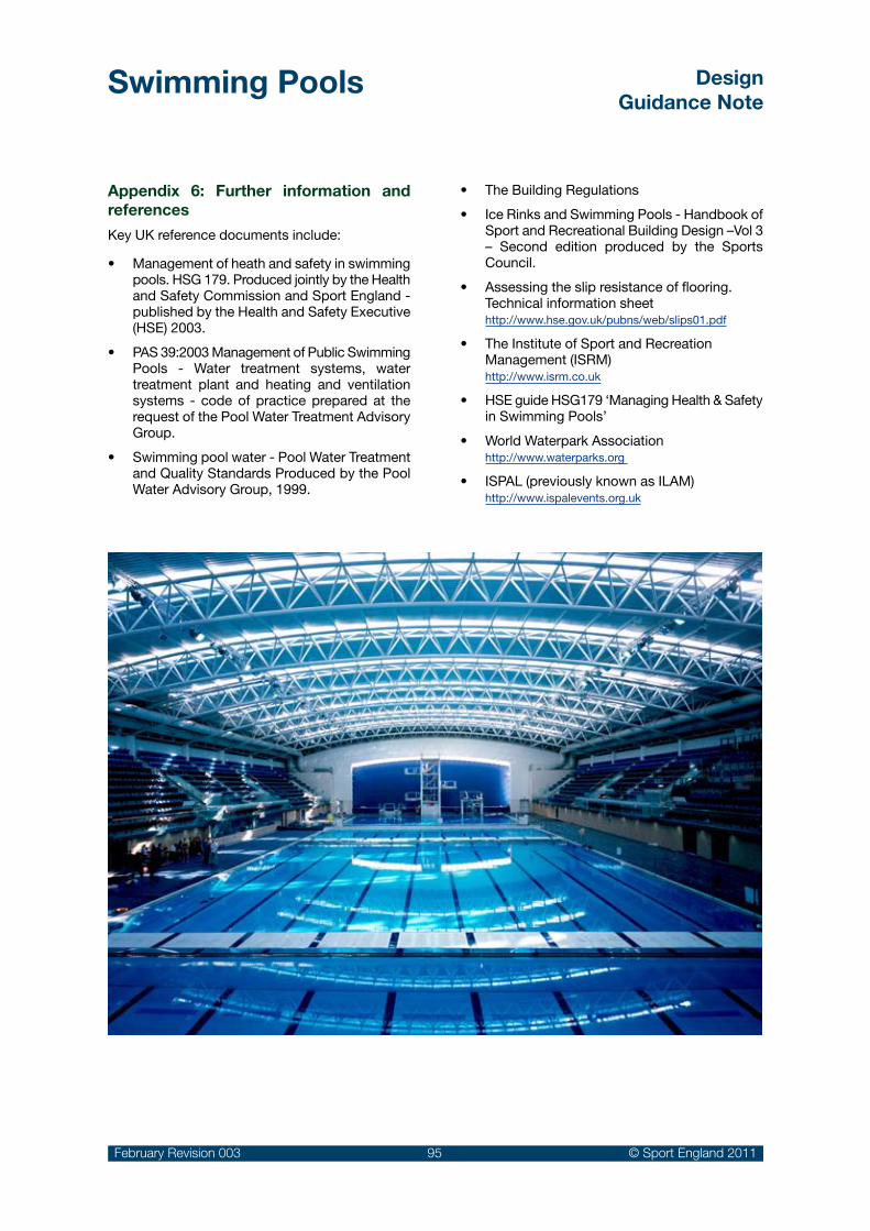
Swimming Pools DesignGuidance Note
February Revision 003 95 © Sport England 2011
Appendix 6: Further information and references
Key UK reference documents include:
Management of heath and safety in swimming •pools. HSG 179. Produced jointly by the Health and Safety Commission and Sport England - published by the Health and Safety Executive (HSE) 2003.
PAS 39:2003 Management of Public Swimming •Pools - Water treatment systems, water treatment plant and heating and ventilation systems - code of practice prepared at the request of the Pool Water Treatment Advisory Group.
Swimming pool water - Pool Water Treatment •and Quality Standards Produced by the Pool Water Advisory Group, 1999.
The Building Regulations•
Ice Rinks and Swimming Pools - Handbook of •Sport and Recreational Building Design –Vol 3 – Second edition produced by the Sports Council.
Assessing the slip resistance of flooring. •Technical information sheet http://www.hse.gov.uk/pubns/web/slips01.pdf
The Institute of Sport and Recreation •Management (ISRM) http://www.isrm.co.uk
HSE guide HSG179 ‘Managing Health & Safety •in Swimming Pools’
World Waterpark Association •http://www.waterparks.org
ISPAL (previously known as ILAM) •http://www.ispalevents.org.uk

Swimming Pools DesignGuidance Note
February Revision 003 96 © Sport England 2011
Alternative languages and Formats:
This document can be provided in alternative languages, or alternative formats such as large print, Braille, tape and on disk upon request.Call the Sport England switchboard on 08458 508 508 for more details.
Information Prepared By:Sport England, Robin Wilson Consulting & S&P Architects
Acknowledgements:Sport England is indebted to the individuals and organisations that have contributed to this guidance notewith excellent advice, information and photographic material. In particular (in alphabetical order):
DisclaimerAmendments, alterations and updates to this document may take place from time to time. When using Sport England Design Guidance you should always download the documents at the time of use in order to ensure that you are referring to the most up-to-date information. The term Design Guidance should be taken to imply the minimum standards required to produce best practice solutions acceptable to Sport England.
This document is for information only. Whilst every effort has been made to ensure the accuracy of this Design Guidance Note and all information contained herein, Sport England, or its agents, shall not be held responsible or liable to any party in respect of any loss, damage or costs of any nature arising directly or indirectly from reliance placed on this information. The views expressed are not intended to take away or diminish the responsibility of the user to comply with current or future legislation and if there are any conflicts between the views expressed in this document and legislation, the latter takes precedence.
Issue Tracker003 – Updated guidance: February 2011002 – Minor text amendments: April 2008001 – Initial Publications: April 2008
Sport England3rd Floor Victoria House Bloomsbury SquareLondonWC1B 4SE
© Sport England, February 2011
Tel : +44 (0)8458 508 508 Fax: +44 (0)20 7383 5740
Email: [email protected]: http://www.sportengland.org
ADM Floors ISRM/ PWTAG: Ralph RileyAmateur Swimming Association LA Architects: Mike LawlessArcblue MSG Consult: Malcolm GrahamArjo UK Myrtha PoolsAustin Design & Manufacture Ltd Power Master Ltd.Barr + Wray Roberts Limbrick: Philip DrydenDavid Bosher Andrew SouthallCarlos Dublanc S&P ArchitectsFeilden Clegg Bradley: Andy Couling The Access Consultancy: Brian TowersHealth & Safety Executive Tim Ronalds ArchitectsKirby Swim Equip Pty Limited Charlotte WoodGreenwich Leisure Ltd: Roy Clarke John Whitby
ISBN 978-1-86078-270-1