swing thruster - lewmar swing thruster... · lewmar swing thruster product and installation manual...
TRANSCRIPT

Swing ThrusterProduct and Installation Manual
500106 -Issue 1

2
2- Safety Notice
1- IntroductionThank you for choosing Lewmar. Lewmar products are world renowned for their quality, technical innovation and proven performance. With a Lewmar product you will be provided with many years of outstanding service.
Product supportLewmar products are supported by a worldwide network of distributors and Authorised Service Repre-sentatives. If you encounter any difficulties with this product, please contact your national distributor, or your local Lewmar dealer. Details are available at: www.lewmar.com
CE ApprovalsFor CE approval certificates contact Lewmar.
Important information about this manualThroughout this manual, you will see safety and product damage warnings. You must follow these warnings carefully to avoid possible injury or damage.
WARNING! IMPORTANT: Read these notes before continuing.
• Read this manual thoroughly and ensure that you fully understand the operation and safety requirements of the thruster before commencing the installation and operating the product.
• Only persons who are completely familiar with the controls and those who have been fully made aware of the correct use of the thruster should be allowed to use it. If there is any doubt of how to install or operate this unit please seek advice from a suitably qualified engineer.
• Please ensure that you thoroughly understand the operation and safety requirements of the thruster.• Your thruster should not be operated close to swimmers, as a powerful suction of water is generated
when in use.• The thruster must not be used at speeds above 6 knots, and must be retracted at that speed.• The tunnel installation and any hull modifications should only be carried out by a specialist. This manual
is based on a GRP tunnel installation.• Do not use the thruster for ANY purpose other than mooring aid. • We recommend that a qualified person install the thruster. Faulty installation will place the boat and crew
in danger and make the warranty invalid.• A circuit breaker/isolator should always be used with the thruster to protect the motor and cables from
overheating and damage.• Always switch off the thruster at circuit breaker/isolator when not in use.• It is the unavoidable responsibility of the captain (owner, master or other responsible party) to assess
the risk of any operation on the vessel. the captain is responsible for the safety of the vessel, the crew, passengers and any thid party at all times.
• Thrusters must not be operated whilst under the influence of alcohol or drugs.
3.2 Fitting• This equipment must be installed and operated in accordance with the instructions contained in this
manual. Failure to do so could result in poor product performance, personal injury and/or damage to your boat.
• Consult the boat manufacturer if you have any doubt about the strength or suitability of the mounting location.
3.3 Electrical• Make sure you have switched off the power before you start installing this product.• This product requires installation by a suitably qualified electrical engineer.

Lewmar Swing Thruster Product and Installation Manual ref 500146 iss.1 | 3
3- Installation instructions
Kit includes the following parts:
Description NumberHandbook 1Installation instructions 1Bowthruster with motor and tube 1Bolts for connecting the motor 4Washers for connecting the motor 4Stop plate for brace* 1
Description NumberDrive shaft 1Plastic shear pin for actuator (spare) 1Metal shear pin for thruster (spare)* 1Fuse holder 1Fuse 1
*Not for model 250.
Start by marking out the centre line on the outside of the hull, e.g. by sighting between a point right forward and the keel. Measure of the position of the hatch using the 3 mm hole drilled in step 2. The size of the hatch is shown in the table below.
140 tunnel B=220 mm L=274 mm185 tunnel B=255 mm L=346 mm250 tunnel B=375 mm L=480 mm
The bowthruster should be placed as far forward as possible, without the top of the box coming above the waterline, otherwise it could be difficult to fit or remove the motor. Measure out the most suitable location from inside the boat. Drill a 3 mm hole as close as possible to the centre line, within the area in which the hatch will be taken up. This hole will be used as a reference point for locating the mould on the outside of the hull. The installation kit does not include the mould, since the mould must be manu-factured on site in order to fit the shape of the hull of your boat.
3.1 Mark out the position fore and aft
3.2 Placing the mould

4
Cut the marked up hole in the hull with a jigsaw. We recommend you cut with an angle of 40 degrees to the hull (see picture below).
40°
Hull
Centre line
Hull
A
Box
140 tunnel A=160-170 mm185 tunnel A=200-210 mm250 tunnel A=300 mm
Locate the box with the inside of the after edge a maximum of the width of the flange (10 mm) aft of the hole. Measure out dimension A and calculate the difference between the measured dimension A and the value for A given in the table. Transfer this measurement to the fore-and-aft side of the box using a marking gauge. Cut the box to this line. The thwartships sides (fore and aft) are fitted to the shape of the inside of the hull. Put the box in place and check that dimension A has been accurately marked.
3.3 Fitting the box
Sand the outside of the box for a height of about 10 cm all-round to ensure good adhesion to the plastic.
Locate the internal rear edge of the box a maximum of the width of the flange (10 mm) aft of the open-ing. Adjust the lateral position of the box until the thruster tunnel goes down through the hole and the clearance on each side of the tunnel is the same, so that it is centred athwartships. Then attach the box using a little rapid-curing filler. Check carefully that the sides of the box are not concave. If they have become concave, the sides of the box must be pushed out with a strut while the box is being glassed-in.
Then check that the tunnel can move freely, and that, when it is deployed, the thruster wash will miss the hull.
NB! Do not apply the final laminations until the hatch has been fitted. Check carefully that the hatch clears the hull
3.4a Installing the box (standard)

Lewmar Swing Thruster Product and Installation Manual ref 500146 iss.1 | 5
A flange base version is available for high volume customers performing installations in the same loca-tion repetitively. This requires an appropriate recess moulding in the hull and a custom box producing by Lewmar to fit it. Please contact Lewmar for further information on this facility.
3.4b Installing the box (flange base)
The flange base thruster is supplied as a complete unit. The bottom flange is custom made to match the contour of the hull. The hatch is also pre-fitted to the tunnel.
Ensure moulded recess in hull is clean and ready for bonding. Exact details on preparatory steps should be taken from the instructions from the bonding agent to be used.
Perform the recommended preparatory work to the flange of the thruster box itself. Apply the chosen bonding agent as instructed and position the box into the recess, holding in place using strapping or suitable support for the duration of the stated curing time.
Once the bonding agent has cured, finish and fair the installation as required to achieve a seamless blend between flange and hull.
Proceed to step 3.9
6
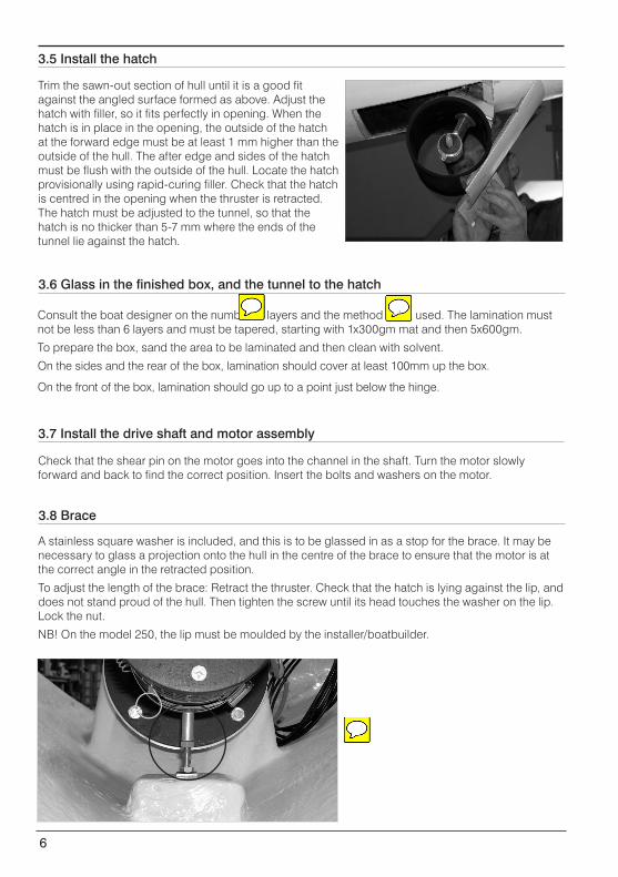
Trim the sawn-out section of hull until it is a good fit against the angled surface formed as above. Adjust the hatch with filler, so it fits perfectly in opening. When the hatch is in place in the opening, the outside of the hatch at the forward edge must be at least 1 mm higher than the outside of the hull. The after edge and sides of the hatch must be flush with the outside of the hull. Locate the hatch provisionally using rapid-curing filler. Check that the hatch is centred in the opening when the thruster is retracted. The hatch must be adjusted to the tunnel, so that the hatch is no thicker than 5-7 mm where the ends of the tunnel lie against the hatch.
A stainless square washer is included, and this is to be glassed in as a stop for the brace. It may be necessary to glass a projection onto the hull in the centre of the brace to ensure that the motor is at the correct angle in the retracted position.
To adjust the length of the brace: Retract the thruster. Check that the hatch is lying against the lip, and does not stand proud of the hull. Then tighten the screw until its head touches the washer on the lip. Lock the nut.
NB! On the model 250, the lip must be moulded by the installer/boatbuilder.
3.5 Install the hatch
Consult the boat designer on the number of layers and the method to be used. The lamination must not be less than 6 layers and must be tapered, starting with 1x300gm mat and then 5x600gm.
To prepare the box, sand the area to be laminated and then clean with solvent.
On the sides and the rear of the box, lamination should cover at least 100mm up the box.
On the front of the box, lamination should go up to a point just below the hinge.
3.6 Glass in the finished box, and the tunnel to the hatch
Check that the shear pin on the motor goes into the channel in the shaft. Turn the motor slowly forward and back to find the correct position. Insert the bolts and washers on the motor.
3.7 Install the drive shaft and motor assembly
3.8 Brace
Lewmar Swing Thruster Product and Installation Manual ref 500146 iss.1 | 7
The panel must be installed in a dry location. The rear of the panel is not watertight, and must be protected against water entry.
Yellow
White
Green
Brown
Heat fuse
Contactor
White
Circuit diagram Electric motor
Panel
Win
dlas
s
Aut
o
Motor Cable Bat
tery
Isol
ator
1. Pink2. Grey3. Blue4. Red5. Yellow6. Brown7. White8. Green
1. Red2. Yellow3. Green4. Brown5. Pink6. Grey7. White8. Blue
1. White2. Brown3. green4. Yellow
White Common plusBrown Up/DownYellow Up/Down
Red +12/24VBlue GNDPink not in useGrey not in use
1. White2. Brown
Brown
White
Green
Yellow
Battery power
White
Battery isolator
Contactor
Windlass
PanelOn/Off
PRTSTB
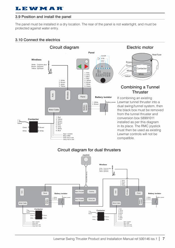
3.9 Position and install the panel
3.10 Connect the electrics
Combining a Tunnel Thruster
If combining an existing Lewmar tunnel thruster into a dual swing/tunnel system, then the black box must be removed from the tunnel thruster and conversion box 58991011 installed as per this diagram in its place. The RMC joystick must then be used as existing Lewmar controls will not be compatible.
PanelAut
o
Motor Cable Bat
tery
Isol
ator
Red +12/24VBlue GNDPink not in useGrey not in use
1. White2. Brown
Brown
White
Green
Yellow
Battery power
White
Battery isolator
Contactor
Joystick
Panel
Win
dlas
s
Aut
o
Motor Cable Bat
tery
Isol
ator
1. Red2. Yellow3. Green4. Brown5. Pink6. Grey7. White8. Blue
1. White2. Brown3. green4. Yellow
White Common plusBrown Up/DownYellow Up/Down
Red +12/24VBlue GNDPink not in useGrey not in use
1. White2. Brown
Brown
White
Green
Yellow
Battery power
White
Battery isolator
Contactor
Windlass
Bow Thruster
Stern Thruster
Drive Unit
Comms.
To rear plugs of box
Circuit diagram for dual thrusters

8
If, after the installation has been completed, the tunnel is not sufficiently clear of the hull in the deployed position, you can adjust the vertical position of the tunnel using an adjustment screw. Slacken the nut (1) on the forward edge of the fitting slightly and tighten the nyloc nut (2) on the after edge of the fitting until the water flow through the tunnel is not disturbed by the hull. Then lock the adjustment by tightening the nut (1) again.
12
3.11 Adjustments
Next, adjust bracket (3) so that the side support bolt (4) is centred on its surface when the thruster is in the fully deployed position. To do this, loosen the nut holding on the bracket (3), move position and re-tighten nut.
3
4
Finally, adjust bolt 4 so that there is a gap between the end of the bolt and the side support bracket of 0.5-1mm. The bolts on either should not press on to the brackets when the thruster is not running.

Lewmar Swing Thruster Product and Installation Manual ref 500146 iss.1 | 9
4- Operation
1. On/off2. Starboard3. Port4. Green LED
1
23
41
23
4
WARNING! The protective cover should be in place when the panel is not in use.
WARNING! The main switch must be in the off position if the thruster is to be serviced from outside.
Deploy the thruster by holding down the on/off button (1) for about two seconds. The green LED (4) will start flashing. The thruster is ready for use when the LED shines continuously. Hold down the on/off but-ton to retract the thruster when you are finished.
4.1 Manoeuvring
The thruster can be set to auto-retract automatically after 2 or 5 minutes after the last button press. This auto-retract function can be set as follows:1. Check that the panel is switched off, i.e. the LED is not lit.2. Press the PT button or move the joystick to port. You will hear a single buzz which indicates that the
auto-retract is OFF.3. Press the PT button or move the joystick to port. You will hear two buzzes which indicates that the
auto-retract is now set after 2 minutes.4. Press the PT button or move the joystick to port. You will hear three buzzes which indicates that the
auto-retract is now set after 5 minutes.The auto-retract function can be changed at any time. Repeat steps 2 to 4 above.
4.4 Auto-retract function settings
An alarm will sound when the thruster is deployed. This alarm can be set at interval of 5, 15 or 60 sec-onds as follows:1. Check that the panel is switched off, i.e. the LED is not lit.2. Press the SB button or move the joystick to starboard. You will hear a single buzz which indicates that
the interval is now 5 s.3. Press the SB button or move the joystick to starboard. You will hear two buzzes which indicates that
the interval is now 15 s.4. Press the SB button or move the joystick to starboard. You will hear three buzzes which indicates that
the interval is now 60 s.The alarm interval can be changed at any time. Repeat steps 2 to 4 above.
4.3 Alarm settings
OverheatingThe bowthruster is fitted with an overheating switch, which shuts off the current if the bowthruster is run for too long and the electric motor overheats. If this happens, the green LED will flash rapidly. When the motor has cooled, the system will reset to normal function automatically. Even if the motor has over-heated, the thruster can still be retracted using the on/off button.
4.2 Error Message

10
5- Accessories and spare parts
Remote controlThe remote control is a useful accessory which makes mooring easier, especially if you are short-handed.
Installation requires the addition of an extra circuit board within the bow thruster electronics box.
Instructions are included in the package. Control panelAnchor windlassAuto
Battery switchElectrical motor
Antenna connectionActuator
connection
Water alarm connection
JoystickA joystick is available for the system. It connects to the rear of the panel.
Foot switchA foot switch with light can be connected simply to a socket on the rear of the panel.
Water detectorThe water detector is installed immediately forward of the box, and sets off an alarm if there is a leak. The alarm sounds a steady signal. The bowthruster can be used normally.

Lewmar Swing Thruster Product and Installation Manual ref 500146 iss.1 | 11
List of parts
PART NO DESCRIPTION58990001 Touch panel
58990002 Joystick panel
58990003 Joystick (small)
68001027 Foot switch
58991003 Control cable 10m to main switch
58992003 Water detector
58992001 Remote control for Swingthruster and anchor windlass
589150 Anode, 140
589350 Anode, 185
589550 Anode, 250
559018 Drive shear pin for model 140
559017 Drive shear pin for model 185
589151 140 propeller
589351 185 propeller
589552 250 propeller, starboard
589551 250 propeller, port
Installing an extra panelThe control panels can be installed in parallel, in which case they will both indicate alike. When the system is activated from one panel, the system starts with both panels active.

12
6 Maintenance
Annual maintenance1. Clean thruster and tunnel as necessary.2. Replace anode if necessary.3. Check that all nuts and bolts are tight.4. Check that the battery cables are still firmly connected.5. Run the bowthruster up and down and check that everything is moving freely.6. Check that the connectors are not corroded.7. Inspect the rubber bellows in the bowthruster articulation. Replace if necessary.
The manufacturer recommends replacement every 5 years.
Other maintenanceReplacement of the drive shear pin on models 140 and 185 only. The shear pin is located below the electric motor. Remove the electric motor, replace the shear pin and fit a new cable tie to lock the shear pin. Refit the electric motor.Replacement of the actuator shear pin. Deploy the bowthruster and switch off the electrical power before the bowthruster is fully extended. This reduces the load on the shear pin. Remove the shear pin and fit the new one. Reconnect the power and run the bowthruster up and down.
Replacement of rubber bellows (RMC Branded Thrusters Only)
The rubber bellows must be replaced every 5 years.1. Remove the drive motor by unscrewing the 4 screws.2. Unscrew the central nut.3. Unscrew the hexagonal screw on the upper side of the motor yoke.4. Deploy the thruster with the actuator.5. Slacken the two hose-clips and lower the hatch, pipe and the sup-
porting arm as one unit.6. Unscrew the eight M6 nuts on the inside of the ring fastener. A
support will then be needed on the outside.7. Lift off the ring fastener.8. Take out the old bellows and fit the new one.9. Place the ring fastener over the rubber bellow, so that the bellows
sits correctly in the ring profile. Attach nuts and washers. If the screws were removed, new sealant (butyl) must be applied under the washers on the outside.
10. Apply a little grease to the threads on the supporting arm, thread on the hose-clips and locate them so that they can be tightened.
11. Pass the supporting arm through the bellows and the motor yoke, and fit the central nut.
12. Tighten the hose-clips round the supporting arm.13. Retract the thruster and tighten the hexagonal screw on the motor
supporting arm. Use Loctite.14. Refit the drive motor.15. Test run the up/down function.

Lewmar Swing Thruster Product and Installation Manual ref 500146 iss.1 | 13
If the panel functions are not operating correctly- Check that the extension cable is fitted correctly.- Check the fuse for the electronics.- Check that the power for the electronics is connected correctly.- Check that any circuit-breakers are turned on.
The boat is moving in the wrong direction- Swap over the green and brown cables on the electric motor.
The panel lights up, but the thruster does not work- Check that the battery is charged.- Check that the motor cables are connected correctly.
The thruster does not provide sufficient power or operates in one direction only - The battery is not sufficiently powerful. - Battery cables are too thin. The voltage drop in the cable is excessive. Voltage drop over the
complete wiring run must not exceed 10%. - The thruster is jammed in the tunnel.
The fuse blows repeatedly- Wrong fuse inserted.- The thruster is jammed in the tunnel.
The motor rotates but the thruster does not- The shear pin is broken and needs to be replaced. The shear pin is located below the electric motor.
System voltage:12/24 V
Control system fuse: 5 A
Meets the relevant standards on electromagnetic compatibility
under EN 55 012, EN 60 945, EN 61 000-4-2 and ISO 7637-1/2.
8- Fault finding
7- Technical data

© Copyright 2013 Lewmar Ltd. All rights reserved.
www.lewmar.com
UK & International Distribution
Lewmar / Navtec Southmoor Lane Havant Hampshire PO9 1JJ England
Tel: +44 (0)23 9247 1841 Fax: +44 (0)23 9248 5720 Email: [email protected]
USA
Lewmar / Navtec 351 New Whitfield Street Guilford, CT 06437 USA
Tel: +1 203 458 6200 Fax: +1 203 453 5669 Email: [email protected]
Part No 500106 iss.1