switch 2600 series switch 2600-pwr series...
TRANSCRIPT
Switch 2600 Series Switch 2600-PWR Series Management andSwitch 2800 Series Configuration GuideSwitch 4100 Series Switch 6108
ProCurve Switches
www.procurve.com


ProCurve Switch 2600 Series Switch 2600-PWR Series Switch 2800 Series Switch 4100gl Series Switch 6108
October 2005
Management and Configuration Guide
© Copyright 2000-2005 Hewlett-Packard Development Company, L.P. The information contained herein is subject to change without notice.
Publication Number
5990-6023 October 2005
Applicable Products
ProCurve Switch 2626 ProCurve Switch 2650 ProCurve Switch 2600-8-PWR ProCurve Switch 2626-PWR ProCurve Switch 2650-PWR ProCurve Switch 2824 ProCurve Switch 2848 ProCurve Switch 4104GL ProCurve Switch 4108GL ProCurve Switch 4140GL ProCurve Switch 4148GL ProCurve Switch 4160GL ProCurve Switch 6108
Trademark Credits
(J4900A/B) (J4899A/B) (J8762A) (J8164A) (J8165A) (J4903A) (J4904A) (J4887A) (J4861A/J4865A) (J8151A) (J4888A) (J8152A) (J4902A)
Microsoft, Windows, and Windows NT are US registered trademarks of Microsoft Corporation.
Disclaimer
HEWLETT-PACKARD COMPANY MAKES NO WARRANTY OF ANY KIND WITH REGARD TO THIS MATERIAL, INCLUDING, BUT NOT LIMITED TO, THE IMPLIED WARRANTIES OF MERCHANTABILITY AND FITNESS FOR A PARTICULAR PURPOSE. Hewlett-Packard shall not be liable for errors contained herein or for incidental or consequential damages in connection with the furnishing, performance, or use of this material.
The only warranties for HP products and services are set forth in the express warranty statements accompanying such products and services. Nothing herein should be construed as constituting an additional warranty. HP shall not be liable for technical or editorial errors or omissions contained herein.
Hewlett-Packard assumes no responsibility for the use or reliability of its software on equipment that is not furnished by Hewlett-Packard.
Warranty
See the Customer Support/Warranty booklet included with the product.
A copy of the specific warranty terms applicable to your Hewlett-Packard products and replacement parts can be obtained from your HP Sales and Service Office or authorized dealer.
Hewlett-Packard Company
8000 Foothills Boulevard, m/s 5551
Roseville, California 95747-5551
http://www.procurve.com
Contents
Product Documentation
About Your Switch Manual Set . . . . . . . . . . . . . . . . . . . . . . . . . . . . . . . . . . . . . xv
Feature Index . . . . . . . . . . . . . . . . . . . . . . . . . . . . . . . . . . . . . . . . . . . . . . . . . . xvi
1 Getting Started
Contents . . . . . . . . . . . . . . . . . . . . . . . . . . . . . . . . . . . . . . . . . . . . . . . . . . . . . . . 1-1
Introduction . . . . . . . . . . . . . . . . . . . . . . . . . . . . . . . . . . . . . . . . . . . . . . . . . . . 1-2
Conventions . . . . . . . . . . . . . . . . . . . . . . . . . . . . . . . . . . . . . . . . . . . . . . . . . . . 1-2
Feature Descriptions by Model . . . . . . . . . . . . . . . . . . . . . . . . . . . . . . . . 1-2
Command Syntax Statements . . . . . . . . . . . . . . . . . . . . . . . . . . . . . . . . . 1-3
Command Prompts . . . . . . . . . . . . . . . . . . . . . . . . . . . . . . . . . . . . . . . . . . 1-3
Screen Simulations . . . . . . . . . . . . . . . . . . . . . . . . . . . . . . . . . . . . . . . . . . 1-4
Port Identity Examples . . . . . . . . . . . . . . . . . . . . . . . . . . . . . . . . . . . . . . . 1-4
Sources for More Information . . . . . . . . . . . . . . . . . . . . . . . . . . . . . . . . . . . . 1-4
Need Only a Quick Start? . . . . . . . . . . . . . . . . . . . . . . . . . . . . . . . . . . . . . . . . 1-6
IP Addressing . . . . . . . . . . . . . . . . . . . . . . . . . . . . . . . . . . . . . . . . . . . . . . . 1-6
To Set Up and Install the Switch in Your Network . . . . . . . . . . . . . . . . 1-6
2 Selecting a Management Interface
Contents . . . . . . . . . . . . . . . . . . . . . . . . . . . . . . . . . . . . . . . . . . . . . . . . . . . . . . . 2-1
Overview . . . . . . . . . . . . . . . . . . . . . . . . . . . . . . . . . . . . . . . . . . . . . . . . . . . . . . 2-2
Advantages of Using the Menu Interface . . . . . . . . . . . . . . . . . . . . . . . . . . . . 2-3
Advantages of Using the CLI . . . . . . . . . . . . . . . . . . . . . . . . . . . . . . . . . . . . . . 2-4
Advantages of Using the Web Browser Interface . . . . . . . . . . . . . . . . . . . . . 2-5
Advantages of Using ProCurve Manager or ProCurve Manager Plus . . . . 2-6
iii
3 Using the Menu Interface
Contents . . . . . . . . . . . . . . . . . . . . . . . . . . . . . . . . . . . . . . . . . . . . . . . . . . . . . . . 3-1
Overview . . . . . . . . . . . . . . . . . . . . . . . . . . . . . . . . . . . . . . . . . . . . . . . . . . . . . . 3-2
Starting and Ending a Menu Session . . . . . . . . . . . . . . . . . . . . . . . . . . . . . . . 3-3
How To Start a Menu Interface Session . . . . . . . . . . . . . . . . . . . . . . . . . 3-4
How To End a Menu Session and Exit from the Console: . . . . . . . . . . 3-5
Main Menu Features . . . . . . . . . . . . . . . . . . . . . . . . . . . . . . . . . . . . . . . . . . . . . 3-7
Screen Structure and Navigation . . . . . . . . . . . . . . . . . . . . . . . . . . . . . . . . . . 3-9
Rebooting the Switch . . . . . . . . . . . . . . . . . . . . . . . . . . . . . . . . . . . . . . . . . . . 3-12
Menu Features List . . . . . . . . . . . . . . . . . . . . . . . . . . . . . . . . . . . . . . . . . . . . . 3-14
Where To Go From Here . . . . . . . . . . . . . . . . . . . . . . . . . . . . . . . . . . . . . . . . 3-15
4 Using the Command Line Interface (CLI)
Contents . . . . . . . . . . . . . . . . . . . . . . . . . . . . . . . . . . . . . . . . . . . . . . . . . . . . . . . 4-1
Overview . . . . . . . . . . . . . . . . . . . . . . . . . . . . . . . . . . . . . . . . . . . . . . . . . . . . . . 4-2
Accessing the CLI . . . . . . . . . . . . . . . . . . . . . . . . . . . . . . . . . . . . . . . . . . . . . . . 4-2
Using the CLI . . . . . . . . . . . . . . . . . . . . . . . . . . . . . . . . . . . . . . . . . . . . . . . . . . . 4-2
Privilege Levels at Logon . . . . . . . . . . . . . . . . . . . . . . . . . . . . . . . . . . . . . 4-3
Privilege Level Operation . . . . . . . . . . . . . . . . . . . . . . . . . . . . . . . . . . . . . 4-4Operator Privileges . . . . . . . . . . . . . . . . . . . . . . . . . . . . . . . . . . . . . . 4-4Manager Privileges . . . . . . . . . . . . . . . . . . . . . . . . . . . . . . . . . . . . . . . 4-5
How To Move Between Levels . . . . . . . . . . . . . . . . . . . . . . . . . . . . . . . . 4-7
Listing Commands and Command Options . . . . . . . . . . . . . . . . . . . . . . 4-8Listing Commands Available at Any Privilege Level . . . . . . . . . . . 4-8Command Option Displays . . . . . . . . . . . . . . . . . . . . . . . . . . . . . . . 4-10
Displaying CLI "Help" . . . . . . . . . . . . . . . . . . . . . . . . . . . . . . . . . . . . . . . 4-11
Configuration Commands and the Context Configuration Modes . . 4-13
CLI Control and Editing . . . . . . . . . . . . . . . . . . . . . . . . . . . . . . . . . . . . . . . . . 4-16
5 Using the Web Browser Interface
Contents . . . . . . . . . . . . . . . . . . . . . . . . . . . . . . . . . . . . . . . . . . . . . . . . . . . . . . . 5-1
Overview . . . . . . . . . . . . . . . . . . . . . . . . . . . . . . . . . . . . . . . . . . . . . . . . . . . . . . 5-2
General Features . . . . . . . . . . . . . . . . . . . . . . . . . . . . . . . . . . . . . . . . . . . . . . . 5-3
iv
Starting a Web Browser Interface Session with the Switch . . . . . . . . . . . . 5-4
Using a Standalone Web Browser in a PC or UNIX Workstation . . . . 5-4
Using ProCurve Manager (PCM) or ProCurve Manager Plus (PCM+) . . . . . . . . . . . . . . . . . . . . . . . . . . . . . . . . . . . . . . . . . . . . . . . . . . . . 5-5
Tasks for Your First Web Browser Interface Session . . . . . . . . . . . . . . . . . 5-7
Viewing the “First Time Install” Window . . . . . . . . . . . . . . . . . . . . . . . . 5-7
Creating Usernames and Passwords in the Browser Interface . . . . . . 5-8Using the Passwords . . . . . . . . . . . . . . . . . . . . . . . . . . . . . . . . . . . . 5-10Using the User Names . . . . . . . . . . . . . . . . . . . . . . . . . . . . . . . . . . . 5-10If You Lose a Password . . . . . . . . . . . . . . . . . . . . . . . . . . . . . . . . . . 5-11
Online Help for the Web Browser Interface . . . . . . . . . . . . . . . . . . . . 5-11
Support/Mgmt URLs Feature . . . . . . . . . . . . . . . . . . . . . . . . . . . . . . . . . . . . 5-12
Support URL . . . . . . . . . . . . . . . . . . . . . . . . . . . . . . . . . . . . . . . . . . . . . . 5-13
Help and the Management Server URL . . . . . . . . . . . . . . . . . . . . . . . . 5-13
Status Reporting Features . . . . . . . . . . . . . . . . . . . . . . . . . . . . . . . . . . . . . . . 5-15
The Overview Window . . . . . . . . . . . . . . . . . . . . . . . . . . . . . . . . . . . . . . 5-15
The Port Utilization and Status Displays . . . . . . . . . . . . . . . . . . . . . . . 5-16Port Utilization . . . . . . . . . . . . . . . . . . . . . . . . . . . . . . . . . . . . . . . . . 5-16Port Status . . . . . . . . . . . . . . . . . . . . . . . . . . . . . . . . . . . . . . . . . . . . . 5-18
The Alert Log . . . . . . . . . . . . . . . . . . . . . . . . . . . . . . . . . . . . . . . . . . . . . . 5-19Sorting the Alert Log Entries . . . . . . . . . . . . . . . . . . . . . . . . . . . . . 5-19Alert Types and Detailed Views . . . . . . . . . . . . . . . . . . . . . . . . . . . 5-20
The Status Bar . . . . . . . . . . . . . . . . . . . . . . . . . . . . . . . . . . . . . . . . . . . . . 5-22
Setting Fault Detection Policy . . . . . . . . . . . . . . . . . . . . . . . . . . . . . . . . 5-23
6 Switch Memory and Configuration
Contents . . . . . . . . . . . . . . . . . . . . . . . . . . . . . . . . . . . . . . . . . . . . . . . . . . . . . . . 6-1
Overview . . . . . . . . . . . . . . . . . . . . . . . . . . . . . . . . . . . . . . . . . . . . . . . . . . . . . . 6-2
Overview of Configuration File Management . . . . . . . . . . . . . . . . . . . . . . . . 6-2
Using the CLI To Implement Configuration Changes . . . . . . . . . . . . . . . . . 6-5
Using the Menu and Web Browser Interfaces To Implement Configuration Changes . . . . . . . . . . . . . . . . . . . . . . . . . . . . . . . . . . . . . . . . . . 6-8
Configuration Changes Using the Menu Interface . . . . . . . . . . . . . . . . 6-8Using Save and Cancel in the Menu Interface . . . . . . . . . . . . . . . . 6-9Rebooting from the Menu Interface . . . . . . . . . . . . . . . . . . . . . . . 6-10
Configuration Changes Using the Web Browser Interface . . . . . . . . 6-11
v
Using Primary and Secondary Flash Image Options . . . . . . . . . . . . . . . . . 6-12
Displaying the Current Flash Image Data . . . . . . . . . . . . . . . . . . . . . . 6-12
Switch Software Downloads . . . . . . . . . . . . . . . . . . . . . . . . . . . . . . . . . 6-14
Local Switch Software Replacement and Removal . . . . . . . . . . . . . . 6-15
Rebooting the Switch . . . . . . . . . . . . . . . . . . . . . . . . . . . . . . . . . . . . . . . 6-17
Operating Notes . . . . . . . . . . . . . . . . . . . . . . . . . . . . . . . . . . . . . . . . . . . . 6-19
7 Interface Access and System Information
Contents . . . . . . . . . . . . . . . . . . . . . . . . . . . . . . . . . . . . . . . . . . . . . . . . . . . . . . . 7-1
Overview . . . . . . . . . . . . . . . . . . . . . . . . . . . . . . . . . . . . . . . . . . . . . . . . . . . . . . 7-2
Interface Access: Console/Serial Link, Web, and Telnet . . . . . . . . . . . . . . . 7-3
Menu: Modifying the Interface Access . . . . . . . . . . . . . . . . . . . . . . . . . . 7-4
CLI: Modifying the Interface Access . . . . . . . . . . . . . . . . . . . . . . . . . . . . 7-5
Denying Interface Access by Terminating Remote Management Sessions . . . . . . . . . . . . . . . . . . . . . . . . . . . . . . . . . . . . . . . . . . . . . . . . . . . . . . . 7-9
System Information . . . . . . . . . . . . . . . . . . . . . . . . . . . . . . . . . . . . . . . . . . . . 7-10
Menu: Viewing and Configuring System Information . . . . . . . . . . . . . 7-11
CLI: Viewing and Configuring System Information . . . . . . . . . . . . . . 7-12
Web: Configuring System Parameters . . . . . . . . . . . . . . . . . . . . . . . . . 7-15
8 Configuring IP Addressing
Contents . . . . . . . . . . . . . . . . . . . . . . . . . . . . . . . . . . . . . . . . . . . . . . . . . . . . . . . 8-1
Overview . . . . . . . . . . . . . . . . . . . . . . . . . . . . . . . . . . . . . . . . . . . . . . . . . . . . . . 8-2
IP Configuration . . . . . . . . . . . . . . . . . . . . . . . . . . . . . . . . . . . . . . . . . . . . . . . . 8-3
Just Want a Quick Start with IP Addressing? . . . . . . . . . . . . . . . . . . . . 8-4
IP Addressing with Multiple VLANs . . . . . . . . . . . . . . . . . . . . . . . . . . . . 8-4
IP Addressing in a Stacking Environment . . . . . . . . . . . . . . . . . . . . . . . 8-5
Menu: Configuring IP Address, Gateway, and Time-To-Live (TTL) . . 8-5
CLI: Configuring IP Address, Gateway, and Time-To-Live (TTL) . . . . 8-7
Web: Configuring IP Addressing . . . . . . . . . . . . . . . . . . . . . . . . . . . . . . 8-11
How IP Addressing Affects Switch Operation . . . . . . . . . . . . . . . . . . . 8-11DHCP/Bootp Operation . . . . . . . . . . . . . . . . . . . . . . . . . . . . . . . . . . 8-12Network Preparations for Configuring DHCP/Bootp . . . . . . . . . 8-15
vi
IP Preserve: Retaining VLAN-1 IP Addressing Across Configuration File Downloads . . . . . . . . . . . . . . . . . . . . . . . . . . . . . . . . . . . . . . . . . . . . . . . . 8-16
Operating Rules for IP Preserve . . . . . . . . . . . . . . . . . . . . . . . . . . . . . . 8-16
9 Time Protocols
Contents . . . . . . . . . . . . . . . . . . . . . . . . . . . . . . . . . . . . . . . . . . . . . . . . . . . . . . . 9-1
Overview . . . . . . . . . . . . . . . . . . . . . . . . . . . . . . . . . . . . . . . . . . . . . . . . . . . . . . 9-2
TimeP Time Synchronization . . . . . . . . . . . . . . . . . . . . . . . . . . . . . . . . . . 9-2
SNTP Time Synchronization . . . . . . . . . . . . . . . . . . . . . . . . . . . . . . . . . . 9-2
Overview: Selecting a Time Synchronization Protocol or Turning OffTime Protocol Operation . . . . . . . . . . . . . . . . . . . . . . . . . . . . . . . . . . . . . . . . . 9-3
General Steps for Running a Time Protocol on the Switch . . . . . . . . . 9-3
Disabling Time Synchronization . . . . . . . . . . . . . . . . . . . . . . . . . . . . . . . 9-4
SNTP: Viewing, Selecting, and Configuring . . . . . . . . . . . . . . . . . . . . . . . . . 9-4
Menu: Viewing and Configuring SNTP . . . . . . . . . . . . . . . . . . . . . . . . . . 9-5
CLI: Viewing and Configuring SNTP . . . . . . . . . . . . . . . . . . . . . . . . . . . . 9-8Viewing the Current SNTP Configuration . . . . . . . . . . . . . . . . . . . . 9-8Configuring (Enabling or Disabling) the SNTP Mode . . . . . . . . . . 9-9
TimeP: Viewing, Selecting, and Configuring . . . . . . . . . . . . . . . . . . . . . . . . 9-14
Menu: Viewing and Configuring TimeP . . . . . . . . . . . . . . . . . . . . . . . . 9-15
CLI: Viewing and Configuring TimeP . . . . . . . . . . . . . . . . . . . . . . . . . . 9-16Viewing the Current TimeP Configuration . . . . . . . . . . . . . . . . . . 9-17Configuring (Enabling or Disabling) the TimeP Mode . . . . . . . . 9-18
SNTP Unicast Time Polling with Multiple SNTP Servers . . . . . . . . . . . . . 9-21
Address Prioritization . . . . . . . . . . . . . . . . . . . . . . . . . . . . . . . . . . . . . . . 9-22
Adding and Deleting SNTP Server Addresses . . . . . . . . . . . . . . . . . . . 9-22
Menu Interface Operation with Multiple SNTP Server Addresses Configured . . . . . . . . . . . . . . . . . . . . . . . . . . . . . . . . . . . . . . . . . . . . . . . . 9-24
SNTP Messages in the Event Log . . . . . . . . . . . . . . . . . . . . . . . . . . . . . . . . . 9-24
10 Port Status and Basic Configuration
Contents . . . . . . . . . . . . . . . . . . . . . . . . . . . . . . . . . . . . . . . . . . . . . . . . . . . . . . 10-1
Overview . . . . . . . . . . . . . . . . . . . . . . . . . . . . . . . . . . . . . . . . . . . . . . . . . . . . . 10-3
Viewing Port Status and Configuring Port Parameters . . . . . . . . . . . . . . . 10-3
vii

Menu: Viewing Port Status and Configuring Port Parameters . . . . . 10-6
CLI: Viewing Port Status and Configuring Port Parameters . . . . . . . 10-7
Manual Auto-MDIX Override on the Series 2600/2600-PWR
Configuring Port-Based Priority for Incoming Packets on the
Using the CLI To View Port Status . . . . . . . . . . . . . . . . . . . . . . . . 10-8Displaying Spanning Tree Configuration Details . . . . . . . . . . . . 10-10Using the CLI To Configure Ports . . . . . . . . . . . . . . . . . . . . . . . . 10-10Using the CLI To Configure a Broadcast Limit . . . . . . . . . . . . . . 10-11Configuring HP Auto-MDIX . . . . . . . . . . . . . . . . . . . . . . . . . . . . . 10-13
and 2800 Switches . . . . . . . . . . . . . . . . . . . . . . . . . . . . . . . . . . . . . 10-14
Web: Viewing Port Status and Configuring Port Parameters . . . . . 10-17
Jumbo Packets on the Series 2800 Switches . . . . . . . . . . . . . . . . . . . . . . 10-17
Terminology . . . . . . . . . . . . . . . . . . . . . . . . . . . . . . . . . . . . . . . . . . . . . . 10-18
Operating Rules . . . . . . . . . . . . . . . . . . . . . . . . . . . . . . . . . . . . . . . . . . . 10-18
Configuring Jumbo Packet Operation . . . . . . . . . . . . . . . . . . . . . . . . 10-19Overview . . . . . . . . . . . . . . . . . . . . . . . . . . . . . . . . . . . . . . . . . . . . . 10-19Viewing the Current Jumbo Configuration . . . . . . . . . . . . . . . . . 10-20Enabling or Disabling Jumbo Traffic on a VLAN . . . . . . . . . . . . 10-22
Operating Notes for Jumbo Traffic-Handling . . . . . . . . . . . . . . . . . . 10-22
Troubleshooting . . . . . . . . . . . . . . . . . . . . . . . . . . . . . . . . . . . . . . . . . . 10-24
QoS Pass-Through Mode on the Series 2800 and 4100gl Switches . . . . 10-25General Operation . . . . . . . . . . . . . . . . . . . . . . . . . . . . . . . . . . . . . 10-25Priority Mapping With and Without QoS Pass-Through Mode . 10-26How to enable/disable QoS Pass-Through Mode . . . . . . . . . . . . 10-26
4100gl and 6108 Switches . . . . . . . . . . . . . . . . . . . . . . . . . . . . . . . . . . . . . . 10-28
The Role of 802.1Q VLAN Tagging . . . . . . . . . . . . . . . . . . . . . . . . . . . 10-28
Outbound Port Queues and Packet Priority Settings . . . . . . . . . . . . 10-29
Operating Rules for Port-Based Priority . . . . . . . . . . . . . . . . . . . . . . 10-30
Configuring and Viewing Port-Based Priority . . . . . . . . . . . . . . . . . . 10-31
Messages Related to Prioritization . . . . . . . . . . . . . . . . . . . . . . . . . . . 10-32
Troubleshooting Prioritization . . . . . . . . . . . . . . . . . . . . . . . . . . . . . . 10-32
Using Friendly (Optional) Port Names . . . . . . . . . . . . . . . . . . . . . . . . . . . 10-33
Configuring and Operating Rules for Friendly Port Names . . . . . . . 10-33
Configuring Friendly Port Names . . . . . . . . . . . . . . . . . . . . . . . . . . . . 10-34
Displaying Friendly Port Names with Other Port Data . . . . . . . . . . 10-36
viii
11 Power Over Ethernet (PoE) Operation for the Series
2600-PWR Switches
Contents . . . . . . . . . . . . . . . . . . . . . . . . . . . . . . . . . . . . . . . . . . . . . . . . . . . . . . 11-1
Overview . . . . . . . . . . . . . . . . . . . . . . . . . . . . . . . . . . . . . . . . . . . . . . . . . . . . . 11-2
Configuration Options . . . . . . . . . . . . . . . . . . . . . . . . . . . . . . . . . . . . . . 11-2
Related Publications . . . . . . . . . . . . . . . . . . . . . . . . . . . . . . . . . . . . . . . . 11-3
Terminology . . . . . . . . . . . . . . . . . . . . . . . . . . . . . . . . . . . . . . . . . . . . . . . 11-3
Power Availability and Provisioning . . . . . . . . . . . . . . . . . . . . . . . . . . . . . . 11-4
Powered Device (PD) Support . . . . . . . . . . . . . . . . . . . . . . . . . . . . . . . 11-4
Power Priority . . . . . . . . . . . . . . . . . . . . . . . . . . . . . . . . . . . . . . . . . . . . . 11-5
Configuring PoE Operation . . . . . . . . . . . . . . . . . . . . . . . . . . . . . . . . . . . . . . 11-7
Cycling Power on a Port . . . . . . . . . . . . . . . . . . . . . . . . . . . . . . . . . . . . . 11-8
PoE for Pre-802.3af-standard PDs (Switch 2600-8-PWR) . . . . . . . . . . 11-9
Viewing PoE Configuration and Status . . . . . . . . . . . . . . . . . . . . . . . . . . . 11-10
Displaying the Switch’s Global PoE Power Status . . . . . . . . . . . . . . 11-10
Displaying an Overview of PoE Status on All Ports . . . . . . . . . . . . . 11-11
Displaying the PoE Status on Specific Ports . . . . . . . . . . . . . . . . . . . 11-12
Planning and Implementing a PoE Configuration . . . . . . . . . . . . . . . . . . 11-13
Assigning PoE Ports to VLANs . . . . . . . . . . . . . . . . . . . . . . . . . . . . . . 11-13
Applying Security Features to PoE Configurations . . . . . . . . . . . . . 11-13
PoE Event Log Messages . . . . . . . . . . . . . . . . . . . . . . . . . . . . . . . . . . . . . . . 11-14
12 Port Trunking
Contents . . . . . . . . . . . . . . . . . . . . . . . . . . . . . . . . . . . . . . . . . . . . . . . . . . . . . . 12-1
Overview . . . . . . . . . . . . . . . . . . . . . . . . . . . . . . . . . . . . . . . . . . . . . . . . . . . . . 12-2
Port Status and Configuration . . . . . . . . . . . . . . . . . . . . . . . . . . . . . . . . . . . 12-2
Trunk Group Boundary Requirement with IP Routing Enabled
Trunk Group Boundary Requirement for the Series 4100gl
Port Connections and Configuration . . . . . . . . . . . . . . . . . . . . . . . . . . 12-3Link Connections . . . . . . . . . . . . . . . . . . . . . . . . . . . . . . . . . . . . . . . 12-3
on the Series 2800 Switch . . . . . . . . . . . . . . . . . . . . . . . . . . . . . . . . 12-3
Switch 10/100/1000 Module (J4908A) . . . . . . . . . . . . . . . . . . . . . . 12-4
Port Trunk Options and Operation . . . . . . . . . . . . . . . . . . . . . . . . . . . . 12-5
Trunk Configuration Methods . . . . . . . . . . . . . . . . . . . . . . . . . . . . . . . . 12-5
ix
Menu: Viewing and Configuring a Static Trunk Group . . . . . . . . . . . 12-10
CLI: Viewing and Configuring a Static or Dynamic PortTrunk Group . . . . . . . . . . . . . . . . . . . . . . . . . . . . . . . . . . . . . . . . . . . . . 12-12
Using the CLI To View Port Trunks . . . . . . . . . . . . . . . . . . . . . . . 12-12Using the CLI To Configure a Static or Dynamic Trunk Group 12-15
Web: Viewing Existing Port Trunk Groups . . . . . . . . . . . . . . . . . . . . 12-18
Trunk Group Operation Using LACP . . . . . . . . . . . . . . . . . . . . . . . . . 12-18Default Port Operation . . . . . . . . . . . . . . . . . . . . . . . . . . . . . . . . . 12-21LACP Notes and Restrictions . . . . . . . . . . . . . . . . . . . . . . . . . . . . 12-23
Trunk Group Operation Using the “Trunk” Option . . . . . . . . . . . . . . 12-25
How the Switch Lists Trunk Data . . . . . . . . . . . . . . . . . . . . . . . . . . . . 12-25
Outbound Traffic Distribution Across Trunked Links . . . . . . . . . . . 12-26
13 Configuring for Network Management Applications
Contents . . . . . . . . . . . . . . . . . . . . . . . . . . . . . . . . . . . . . . . . . . . . . . . . . . . . . . 13-1
Using SNMP Tools To Manage the Switch . . . . . . . . . . . . . . . . . . . . . . . . . 13-3
Overview . . . . . . . . . . . . . . . . . . . . . . . . . . . . . . . . . . . . . . . . . . . . . . . . . . 13-3
SNMP Management Features . . . . . . . . . . . . . . . . . . . . . . . . . . . . . . . . . 13-4
Configuring for SNMP Access to the Switch . . . . . . . . . . . . . . . . . . . . 13-4
Configuring for SNMP Version 3 Access to the Switch . . . . . . . . . . . 13-5
SNMP Version 3 Commands . . . . . . . . . . . . . . . . . . . . . . . . . . . . . . . . . 13-6SNMPv3 Enable . . . . . . . . . . . . . . . . . . . . . . . . . . . . . . . . . . . . . . . . 13-7
SNMP Version 3 Users . . . . . . . . . . . . . . . . . . . . . . . . . . . . . . . . . . . . . . 13-8Group Access Levels . . . . . . . . . . . . . . . . . . . . . . . . . . . . . . . . . . . 13-11
SNMP Communities . . . . . . . . . . . . . . . . . . . . . . . . . . . . . . . . . . . . . . . 13-12Menu: Viewing and Configuring non-SNMP version 3 Communities . . . . . . . . . . . . . . . . . . . . . . . . . . . . . . . . . . . . . . . . . . 13-14CLI: Viewing and Configuring SNMP Community Names . . . . 13-16
SNMP Notification and Traps . . . . . . . . . . . . . . . . . . . . . . . . . . . . . . . 13-18Trap Features . . . . . . . . . . . . . . . . . . . . . . . . . . . . . . . . . . . . . . . . . 13-20Using the CLI To Enable Authentication Traps . . . . . . . . . . . . . 13-23
Advanced Management: RMON . . . . . . . . . . . . . . . . . . . . . . . . . . . . . . 13-24
LLDP (Link-Layer Discovery Protocol) . . . . . . . . . . . . . . . . . . . . . . . . . . . 13-25
Introduction . . . . . . . . . . . . . . . . . . . . . . . . . . . . . . . . . . . . . . . . . . . . . . 13-25
LLDP Terminology . . . . . . . . . . . . . . . . . . . . . . . . . . . . . . . . . . . . . . . . 13-26
General LLDP Operation . . . . . . . . . . . . . . . . . . . . . . . . . . . . . . . . . . . 13-27Packet Boundaries in a Network Topology . . . . . . . . . . . . . . . . 13-27
x
LLDP Configuration Options . . . . . . . . . . . . . . . . . . . . . . . . . . . . . . . . 13-27
Options for Reading LLDP Information Collected by the Switch . . 13-30
LLDP Standards Compatibility . . . . . . . . . . . . . . . . . . . . . . . . . . . . . . 13-30
LLDP Operating Rules . . . . . . . . . . . . . . . . . . . . . . . . . . . . . . . . . . . . . 13-31
LLDP Operation and Commands . . . . . . . . . . . . . . . . . . . . . . . . . . . . . 13-32Viewing the Current LLDP Configuration . . . . . . . . . . . . . . . . . . 13-32Configuring Global LLDP Packet Controls . . . . . . . . . . . . . . . . . 13-34Configuring SNMP Notification Support . . . . . . . . . . . . . . . . . . . 13-37Configuring Per-Port LLDP Transmit and Receive Modes . . . . 13-39Configuring LLDP Per-Port Advertisement Content . . . . . . . . . 13-39
Displaying Advertisement Data . . . . . . . . . . . . . . . . . . . . . . . . . . . . . . 13-41Displaying Switch Information Available for OutboundAdvertisements . . . . . . . . . . . . . . . . . . . . . . . . . . . . . . . . . . . . . . . . 13-42Displaying LLDP Statistics . . . . . . . . . . . . . . . . . . . . . . . . . . . . . . 13-46
LLDP Operating Notes . . . . . . . . . . . . . . . . . . . . . . . . . . . . . . . . . . . . . 13-49
LLDP and CDP Data Management . . . . . . . . . . . . . . . . . . . . . . . . . . . 13-50LLDP and CDP Neighbor Data . . . . . . . . . . . . . . . . . . . . . . . . . . . 13-50CDP Operation and Commands . . . . . . . . . . . . . . . . . . . . . . . . . . 13-52
A File Transfers
Contents . . . . . . . . . . . . . . . . . . . . . . . . . . . . . . . . . . . . . . . . . . . . . . . . . . . . . . A-1
Overview . . . . . . . . . . . . . . . . . . . . . . . . . . . . . . . . . . . . . . . . . . . . . . . . . . . . . A-2
Downloading Switch Software . . . . . . . . . . . . . . . . . . . . . . . . . . . . . . . . . . . A-2
General Switch Software Download Rules . . . . . . . . . . . . . . . . . . . . . A-3
Using TFTP To Download Switch Software from a Server . . . . . . . . A-3Menu: TFTP Download from a Server to Primary Flash . . . . . . . A-4CLI: TFTP Download from a Server to Primary or Secondary Flash . . . . . . . . . . . . . . . . . . . . . . . . . . . . . . . . . . . . . . . . A-6
Using Secure Copy and SFTP
Using Xmodem to Download Switch Software From a PC or UNIX
. . . . . . . . . . . . . . . . . . . . . . . . . . . . . . . . A-7How It Works . . . . . . . . . . . . . . . . . . . . . . . . . . . . . . . . . . . . . . . . . . A-8The SCP/SFTP Process . . . . . . . . . . . . . . . . . . . . . . . . . . . . . . . . . . A-9Command Options . . . . . . . . . . . . . . . . . . . . . . . . . . . . . . . . . . . . . . A-9Authentication . . . . . . . . . . . . . . . . . . . . . . . . . . . . . . . . . . . . . . . . A-10SCP/SFTP Operating Notes . . . . . . . . . . . . . . . . . . . . . . . . . . . . . A-10
Workstation . . . . . . . . . . . . . . . . . . . . . . . . . . . . . . . . . . . . . . . . . . . . . . A-11Menu: Xmodem Download to Primary Flash . . . . . . . . . . . . . . . A-11CLI: Xmodem Download from a PC or Unix Workstation toPrimary or Secondary Flash . . . . . . . . . . . . . . . . . . . . . . . . . . . . . A-12
xi
Switch-to-Switch Download . . . . . . . . . . . . . . . . . . . . . . . . . . . . . . . . A-14Menu: Switch-to-Switch Download to Primary Flash . . . . . . . . A-14CLI: Switch-To-Switch Downloads . . . . . . . . . . . . . . . . . . . . . . . A-15
Using ProCurve Manager Plus to Update Switch Software . . . . . . . A-16
Troubleshooting TFTP Downloads . . . . . . . . . . . . . . . . . . . . . . . . . . . . . . A-17
Transferring Switch Configurations . . . . . . . . . . . . . . . . . . . . . . . . . . . . . . A-18
Copying Diagnostic Data to a Remote Host, PC, or Unix Workstation . A-21Copying Command Output to a Destination Device . . . . . . . . . A-21Copying Event Log Output to a Destination Device . . . . . . . . . A-22Copying Crash Data Content to a Destination Device . . . . . . . A-22Copying Crash Log Data Content to a Destination Device . . . . A-23
B Monitoring and Analyzing Switch Operation
Contents . . . . . . . . . . . . . . . . . . . . . . . . . . . . . . . . . . . . . . . . . . . . . . . . . . . . . . B-1
Overview . . . . . . . . . . . . . . . . . . . . . . . . . . . . . . . . . . . . . . . . . . . . . . . . . . . . . B-3
Status and Counters Data . . . . . . . . . . . . . . . . . . . . . . . . . . . . . . . . . . . . . . . B-4
Menu Access To Status and Counters . . . . . . . . . . . . . . . . . . . . . . . . . B-5
General System Information . . . . . . . . . . . . . . . . . . . . . . . . . . . . . . . . . B-6Menu Access . . . . . . . . . . . . . . . . . . . . . . . . . . . . . . . . . . . . . . . . . . . B-6CLI Access . . . . . . . . . . . . . . . . . . . . . . . . . . . . . . . . . . . . . . . . . . . . . B-6
Switch Management Address Information . . . . . . . . . . . . . . . . . . . . . . B-7Menu Access . . . . . . . . . . . . . . . . . . . . . . . . . . . . . . . . . . . . . . . . . . . B-7CLI Access . . . . . . . . . . . . . . . . . . . . . . . . . . . . . . . . . . . . . . . . . . . . . B-7
Module Information . . . . . . . . . . . . . . . . . . . . . . . . . . . . . . . . . . . . . . . . B-8Menu: Displaying Port Status . . . . . . . . . . . . . . . . . . . . . . . . . . . . . B-8CLI Access . . . . . . . . . . . . . . . . . . . . . . . . . . . . . . . . . . . . . . . . . . . . . B-8
Port Status . . . . . . . . . . . . . . . . . . . . . . . . . . . . . . . . . . . . . . . . . . . . . . . . B-9Menu: Displaying Port Status . . . . . . . . . . . . . . . . . . . . . . . . . . . . . B-9CLI Access . . . . . . . . . . . . . . . . . . . . . . . . . . . . . . . . . . . . . . . . . . . . . B-9Web Access . . . . . . . . . . . . . . . . . . . . . . . . . . . . . . . . . . . . . . . . . . . . B-9
Viewing Port and Trunk Group Statistics and Flow Control Status B-10Menu Access to Port and Trunk Statistics . . . . . . . . . . . . . . . . . B-11CLI Access To Port and Trunk Group Statistics . . . . . . . . . . . . B-12Web Browser Access To View Port and Trunk Group Statistics B-12
Viewing the Switch’s MAC Address Tables . . . . . . . . . . . . . . . . . . . . B-13Menu Access to the MAC Address Views and Searches . . . . . . B-14CLI Access for MAC Address Views and Searches . . . . . . . . . . B-16
xii
Spanning Tree Protocol (STP) Information . . . . . . . . . . . . . . . . . . . . B-18Menu Access to STP Data . . . . . . . . . . . . . . . . . . . . . . . . . . . . . . . B-18CLI Access to STP Data . . . . . . . . . . . . . . . . . . . . . . . . . . . . . . . . . B-19
Internet Group Management Protocol (IGMP) Status . . . . . . . . . . . B-20
VLAN Information . . . . . . . . . . . . . . . . . . . . . . . . . . . . . . . . . . . . . . . . . B-21
Web Browser Interface Status Information . . . . . . . . . . . . . . . . . . . . B-23
Port and Static Trunk Monitoring Features . . . . . . . . . . . . . . . . . . . . . . . B-24
Switch 6108 and Series 4100gl Switches . . . . . . . . . . . . . . . . . . . . . . B-24
Series 2600, 2600-PWR, and 2800 Switches . . . . . . . . . . . . . . . . . . . . B-24
Menu: Configuring Port and Static Trunk Monitoring . . . . . . . . . . . B-25
CLI: Configuring Port and Static Trunk Monitoring . . . . . . . . . . . . . B-27
Web: Configuring Port Monitoring . . . . . . . . . . . . . . . . . . . . . . . . . . . B-29
C Troubleshooting
Contents . . . . . . . . . . . . . . . . . . . . . . . . . . . . . . . . . . . . . . . . . . . . . . . . . . . . . . C-1
Overview . . . . . . . . . . . . . . . . . . . . . . . . . . . . . . . . . . . . . . . . . . . . . . . . . . . . . C-3
Troubleshooting Approaches . . . . . . . . . . . . . . . . . . . . . . . . . . . . . . . . . . . . C-3
Chassis Over-Temperature Detection . . . . . . . . . . . . . . . . . . . . . . . . . . . . . C-5
Browser or Telnet Access Problems . . . . . . . . . . . . . . . . . . . . . . . . . . . . . . C-6
Unusual Network Activity . . . . . . . . . . . . . . . . . . . . . . . . . . . . . . . . . . . . . . . C-8
General Problems . . . . . . . . . . . . . . . . . . . . . . . . . . . . . . . . . . . . . . . . . . C-8
Prioritization Problems . . . . . . . . . . . . . . . . . . . . . . . . . . . . . . . . . . . . . C-9
IGMP-Related Problems . . . . . . . . . . . . . . . . . . . . . . . . . . . . . . . . . . . . . C-9
LACP-Related Problems . . . . . . . . . . . . . . . . . . . . . . . . . . . . . . . . . . . . C-10
Port-Based Access Control (802.1X)-Related Problems . . . . . . . . . C-10
Radius-Related Problems . . . . . . . . . . . . . . . . . . . . . . . . . . . . . . . . . . . C-13
Spanning-Tree Protocol (STP) and Fast-Uplink Problems . . . . . . . C-15
SSH-Related Problems . . . . . . . . . . . . . . . . . . . . . . . . . . . . . . . . . . . . . C-16
Stacking-Related Problems . . . . . . . . . . . . . . . . . . . . . . . . . . . . . . . . . C-17
TACACS-Related Problems . . . . . . . . . . . . . . . . . . . . . . . . . . . . . . . . . C-18
TimeP, SNTP, or Gateway Problems . . . . . . . . . . . . . . . . . . . . . . . . . C-20
VLAN-Related Problems . . . . . . . . . . . . . . . . . . . . . . . . . . . . . . . . . . . . C-20
Using Logging To Identify Problem Sources . . . . . . . . . . . . . . . . . . . . . . . C-23
xiii
Event Log Operation . . . . . . . . . . . . . . . . . . . . . . . . . . . . . . . . . . . . . . . C-23Menu: Entering and Navigating in the Event Log . . . . . . . . . . . C-25CLI: . . . . . . . . . . . . . . . . . . . . . . . . . . . . . . . . . . . . . . . . . . . . . . . . . . C-26
Debug and Syslog Operation . . . . . . . . . . . . . . . . . . . . . . . . . . . . . . . . C-27
Diagnostic Tools . . . . . . . . . . . . . . . . . . . . . . . . . . . . . . . . . . . . . . . . . . . . . . C-34
Port Auto-Negotiation . . . . . . . . . . . . . . . . . . . . . . . . . . . . . . . . . . . . . . C-34
Ping and Link Tests . . . . . . . . . . . . . . . . . . . . . . . . . . . . . . . . . . . . . . . . C-35Web: Executing Ping or Link Tests . . . . . . . . . . . . . . . . . . . . . . . C-36CLI: Ping or Link Tests . . . . . . . . . . . . . . . . . . . . . . . . . . . . . . . . . C-37
Displaying the Configuration File . . . . . . . . . . . . . . . . . . . . . . . . . . . . C-39CLI: Viewing the Configuration File . . . . . . . . . . . . . . . . . . . . . . C-39Web: Viewing the Configuration File . . . . . . . . . . . . . . . . . . . . . . C-39Listing Switch Configuration and Operation Details for Helpin Troubleshooting . . . . . . . . . . . . . . . . . . . . . . . . . . . . . . . . . . . . . C-40
CLI Administrative and Troubleshooting Commands . . . . . . . . . . . C-42
Restoring the Factory-Default Configuration . . . . . . . . . . . . . . . . . . . . . . C-43Using the CLI . . . . . . . . . . . . . . . . . . . . . . . . . . . . . . . . . . . . . . . . . C-43Using the Clear/Reset Buttons . . . . . . . . . . . . . . . . . . . . . . . . . . . C-43
Restoring a Flash Image . . . . . . . . . . . . . . . . . . . . . . . . . . . . . . . . . . . . . . . C-44
D MAC Address Management
Contents . . . . . . . . . . . . . . . . . . . . . . . . . . . . . . . . . . . . . . . . . . . . . . . . . . . . . . D-1
Overview . . . . . . . . . . . . . . . . . . . . . . . . . . . . . . . . . . . . . . . . . . . . . . . . . . . . . D-2
Determining MAC Addresses in the Switch . . . . . . . . . . . . . . . . . . . . . . . . D-2
Menu: Viewing the Switch’s MAC Addresses . . . . . . . . . . . . . . . . . . . . D-3
CLI: Viewing the Port and VLAN MAC Addresses . . . . . . . . . . . . . . . . D-4
Viewing the MAC Addresses of Connected Devices on Series 2600/2600-PWR, 2800 and 4100gl Switches . . . . . . . . . . . . . . . . . . . D-6
E Daylight Savings Time on ProCurve Switches
Configuring Daylight Savings Time . . . . . . . . . . . . . . . . . . . . . . . . . . . . . . . E-1
xiv
Product Documentation
About Your Switch Manual Set
The switch manual set includes the following:
■ Read Me First - a printed guide shipped with your switch. Provides software update information, product notes, and other information.
■ Installation and Getting Started Guide - a printed guide shipped with your switch. This guide explains how to prepare for and perform the physical installation and connection to your network.
■ Management and Configuration Guide - included as a PDF file on the Documentation CD. This guide describes how to configure, manage, and monitor basic switch operation.
■ Advanced Traffic Management Guide - included as a PDF file on the Documentation CD. This guide explains the configuration and operation of traffic management features such as spanning tree, VLANs, and IP routing.
■ Access Security Guide - included as a PDF file on the Documentation CD. This guide explains the configuration and operation of access security and user authentication features on the switch.
■ Release Notes - posted on the ProCurve web site to provide information on software updates. The release notes describe new features, fixes, and enhancements that become available between revisions of the above guides.
Note For the latest version of all ProCurve switch documentation, including release notes covering recently added features, visit the ProCurve Networking website at http://www.procurve.com. Click on Technical support, and then click on Product manuals.
xv
Product Documentation
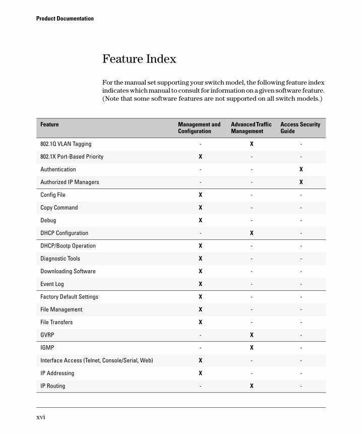
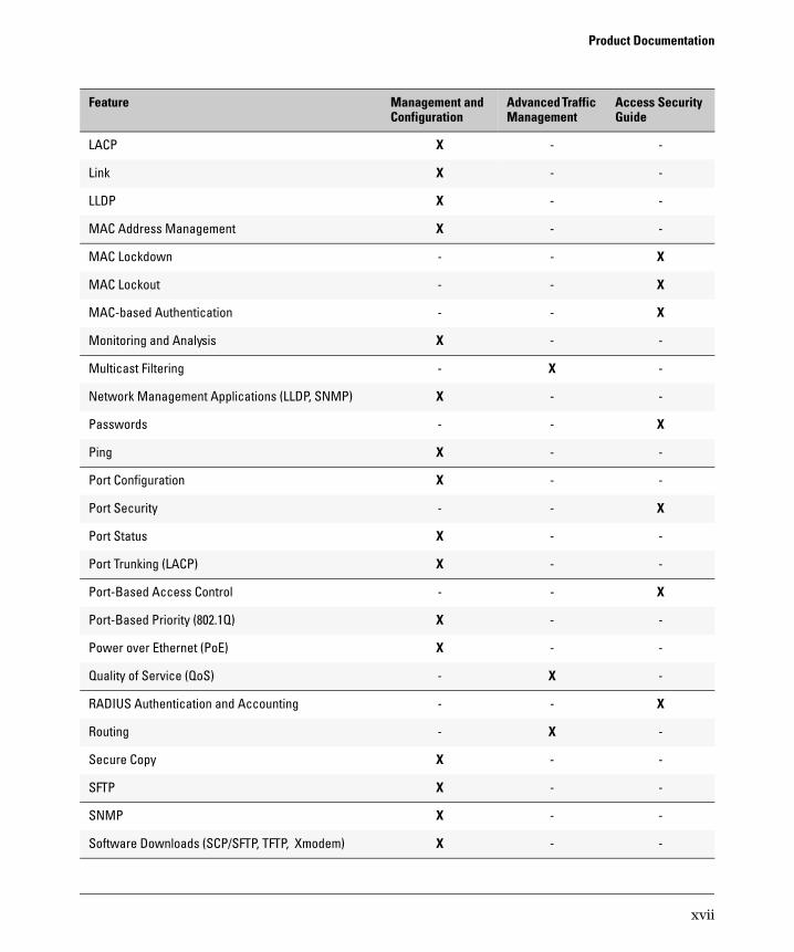
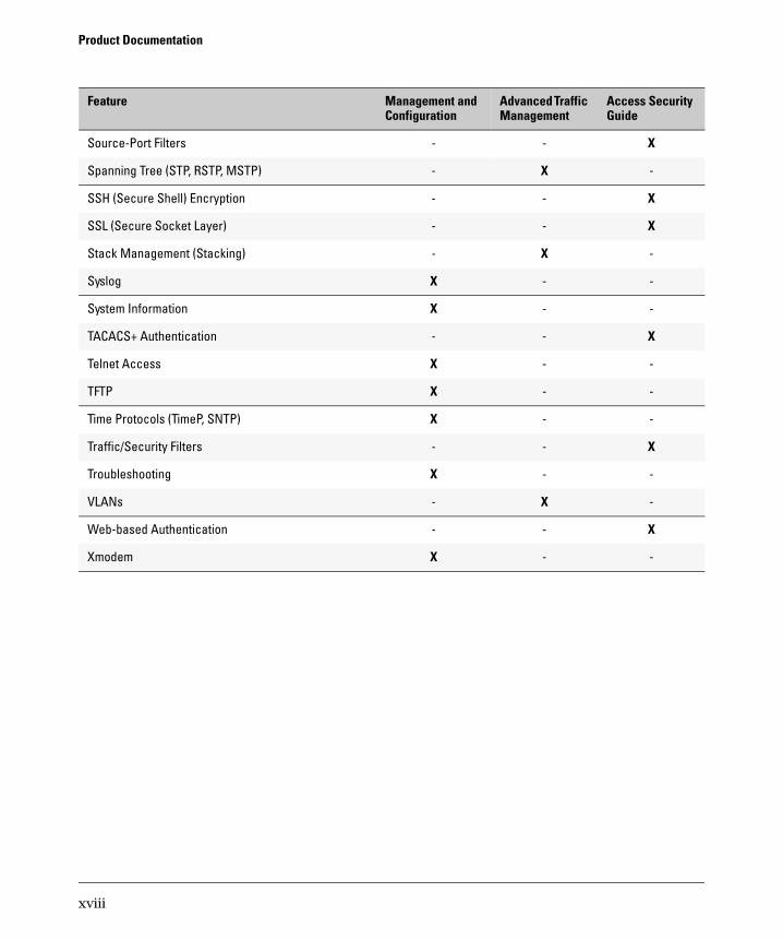
Feature Index
For the manual set supporting your switch model, the following feature index indicates which manual to consult for information on a given software feature. (Note that some software features are not supported on all switch models.)
Configuration Feature Management and Advanced Traffic
Management Access Security Guide
802.1Q VLAN Tagging - X -
802.1X Port-Based Priority X - -
Authentication - - X
Authorized IP Managers - - X
Config File X - -
Copy Command X - -
Debug X - -
DHCP Configuration - X -
DHCP/Bootp Operation X - -
Diagnostic Tools X - -
Downloading Software X - -
Event Log X - -
Factory Default Settings X - -
File Management X - -
File Transfers X - -
GVRP - X -
IGMP - X -
Interface Access (Telnet, Console/Serial, Web) X - -
IP Addressing X - -
IP Routing - X -
xvi
Product Documentation
Configuration Feature Management and Advanced Traffic
Management Access Security Guide
LACP X - -
Link X - -
LLDP X - -
MAC Address Management X - -
MAC Lockdown - - X
MAC Lockout - - X
MAC-based Authentication - - X
Monitoring and Analysis X - -
Multicast Filtering - X -
Network Management Applications (LLDP, SNMP) X - -
Passwords - - X
Ping X - -
Port Configuration X - -
Port Security - - X
Port Status X - -
Port Trunking (LACP) X - -
Port-Based Access Control - - X
Port-Based Priority (802.1Q) X - -
Power over Ethernet (PoE) X - -
Quality of Service (QoS) - X -
RADIUS Authentication and Accounting - - X
Routing - X -
Secure Copy X - -
SFTP X - -
SNMP X - -
Software Downloads (SCP/SFTP, TFTP, Xmodem) X - -
xvii
Product Documentation
Configuration Feature Management and Advanced Traffic
Management Access Security Guide
Source-Port Filters - - X
Spanning Tree (STP, RSTP, MSTP) - X -
SSH (Secure Shell) Encryption - - X
SSL (Secure Socket Layer) - - X
Stack Management (Stacking) - X -
Syslog X - -
System Information X - -
TACACS+ Authentication - - X
Telnet Access X - -
TFTP X - -
Time Protocols (TimeP, SNTP) X - -
Traffic/Security Filters - - X
Troubleshooting X - -
VLANs - X -
Web-based Authentication - - X
Xmodem X - -
xviii
1
Getting Started
Contents
Introduction . . . . . . . . . . . . . . . . . . . . . . . . . . . . . . . . . . . . . . . . . . . . . . . . . . . 1-2
Conventions . . . . . . . . . . . . . . . . . . . . . . . . . . . . . . . . . . . . . . . . . . . . . . . . . . . 1-2
Feature Descriptions by Model . . . . . . . . . . . . . . . . . . . . . . . . . . . . . . . . 1-2
Command Syntax Statements . . . . . . . . . . . . . . . . . . . . . . . . . . . . . . . . . 1-3
Command Prompts . . . . . . . . . . . . . . . . . . . . . . . . . . . . . . . . . . . . . . . . . . 1-3
Screen Simulations . . . . . . . . . . . . . . . . . . . . . . . . . . . . . . . . . . . . . . . . . . 1-4
Port Identity Examples . . . . . . . . . . . . . . . . . . . . . . . . . . . . . . . . . . . . . . . 1-4
Sources for More Information . . . . . . . . . . . . . . . . . . . . . . . . . . . . . . . . . . . . 1-4
Need Only a Quick Start? . . . . . . . . . . . . . . . . . . . . . . . . . . . . . . . . . . . . . . . . 1-6
IP Addressing . . . . . . . . . . . . . . . . . . . . . . . . . . . . . . . . . . . . . . . . . . . . . . . 1-6
To Set Up and Install the Switch in Your Network . . . . . . . . . . . . . . . . 1-6
1-1
Getting Started Introduction
Introduction
This Management and Configuration Guide is intended to support the following switches:
■ ProCurve Series 2600
■ ProCurve Series 2600-PWR
■ ProCurve Series 2800
■ ProCurve Series 4100gl
■ ProCurve Switch 6108
This guide describes how to use the command line interface (CLI), menu interface, and web browser interface to configure, manage, and monitor switch operation. A troubleshooting chapter is also included.
For an overview of other product documentation for the above switches, refer to “Product Documentation” on page xv.
The Product Documentation CD-ROM shipped with the switch includes a copy of this guide. You can also download a copy from the ProCurve website, http://www.procurve.com.
Conventions
This guide uses the following conventions for command syntax and displayed information.
Feature Descriptions by Model
In cases where a software feature is not available in all of the switch models covered by this guide, the section heading specifically indicates which product or product series offer the feature.
For example (the switch model is highlighted here in bold italics):
“QoS Pass-Through Mode on the Series 2800 and 4100gl Switches”.
1-2
Getting Started Conventions
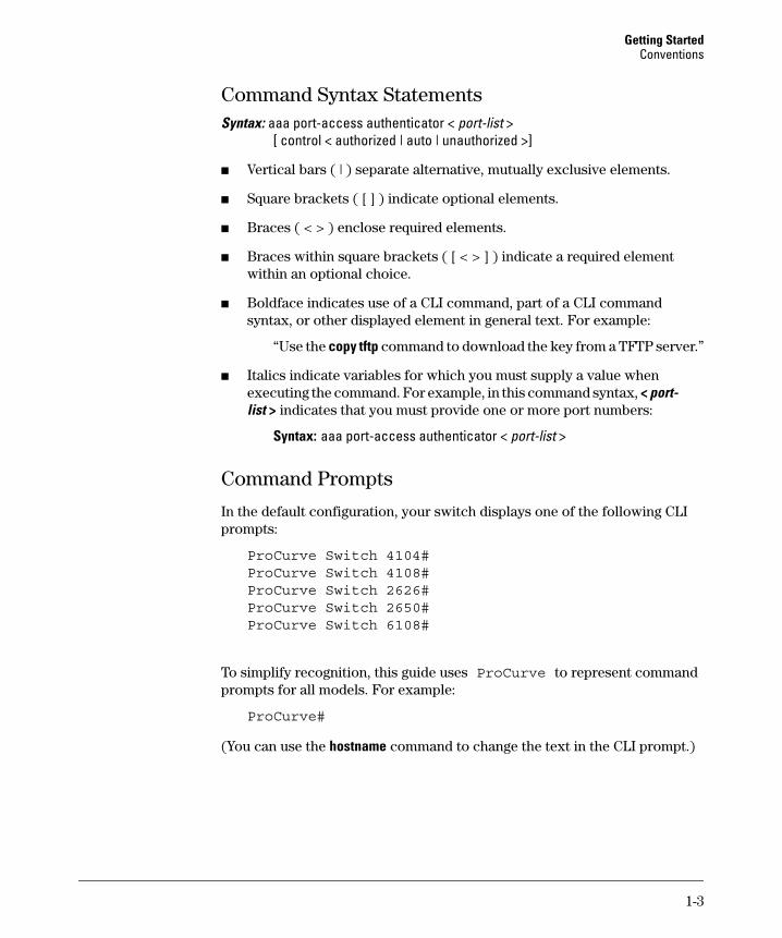
Command Syntax Statements Syntax: aaa port-access authenticator < port-list >
[ control < authorized | auto | unauthorized >]
■ Vertical bars ( | ) separate alternative, mutually exclusive elements.
■ Square brackets ( [ ] ) indicate optional elements.
■ Braces ( < > ) enclose required elements.
■ Braces within square brackets ( [ < > ] ) indicate a required element within an optional choice.
■ Boldface indicates use of a CLI command, part of a CLI command syntax, or other displayed element in general text. For example:
“Use the copy tftp command to download the key from a TFTP server.”
■ Italics indicate variables for which you must supply a value when executing the command. For example, in this command syntax, < port-list > indicates that you must provide one or more port numbers:
Syntax: aaa port-access authenticator < port-list >
Command Prompts
In the default configuration, your switch displays one of the following CLI prompts:
ProCurve Switch 4104#ProCurve Switch 4108#ProCurve Switch 2626#ProCurve Switch 2650#ProCurve Switch 6108#
To simplify recognition, this guide uses ProCurve to represent command prompts for all models. For example:
ProCurve#
(You can use the hostname command to change the text in the CLI prompt.)
1-3
Getting Started Sources for More Information
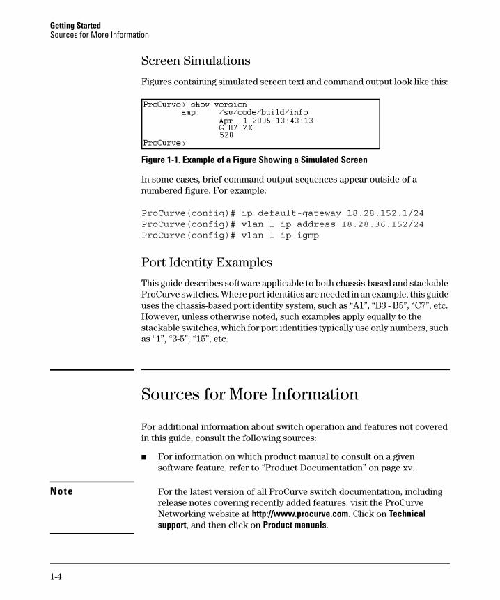
Screen Simulations
Figures containing simulated screen text and command output look like this:
Figure 1-1. Example of a Figure Showing a Simulated Screen
In some cases, brief command-output sequences appear outside of a numbered figure. For example:
ProCurve(config)# ip default-gateway 18.28.152.1/24ProCurve(config)# vlan 1 ip address 18.28.36.152/24ProCurve(config)# vlan 1 ip igmp
Port Identity Examples
This guide describes software applicable to both chassis-based and stackable ProCurve switches. Where port identities are needed in an example, this guide uses the chassis-based port identity system, such as “A1”, “B3 - B5”, “C7”, etc. However, unless otherwise noted, such examples apply equally to the stackable switches, which for port identities typically use only numbers, such as “1”, “3-5”, “15”, etc.
Sources for More Information
For additional information about switch operation and features not covered in this guide, consult the following sources:
■ For information on which product manual to consult on a given software feature, refer to “Product Documentation” on page xv.
Note For the latest version of all ProCurve switch documentation, including release notes covering recently added features, visit the ProCurve Networking website at http://www.procurve.com. Click on Technical support, and then click on Product manuals.
1-4
Getting Started Sources for More Information
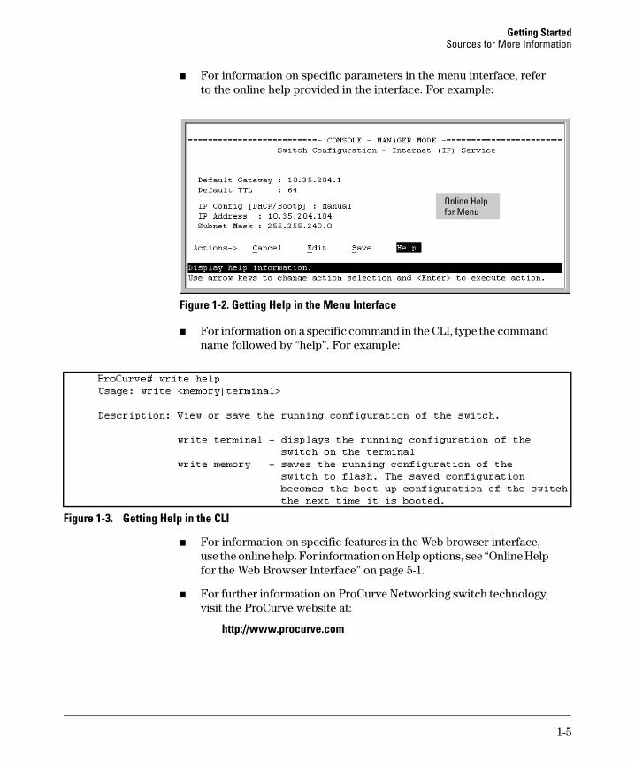
■ For information on specific parameters in the menu interface, refer to the online help provided in the interface. For example:
for Menu Online Help
Figure 1-2. Getting Help in the Menu Interface
■ For information on a specific command in the CLI, type the command name followed by “help”. For example:
Figure 1-3. Getting Help in the CLI
■ For information on specific features in the Web browser interface, use the online help. For information on Help options, see “Online Help for the Web Browser Interface” on page 5-1.
■ For further information on ProCurve Networking switch technology, visit the ProCurve website at:
http://www.procurve.com
1-5
Getting Started Need Only a Quick Start?
Need Only a Quick Start?
IP Addressing
If you just want to give the switch an IP address so that it can communicate on your network, or if you are not using multiple VLANs, ProCurve recommends that you use the Switch Setup screen to quickly configure IP addressing. To do so, do one of the following:
■ Enter setup at the CLI Manager level prompt.
ProCurve# setup
■ In the Main Menu of the Menu interface, select
8. Run Setup
For more on using the Switch Setup screen, see the Installation and Getting
Started Guide you received with the switch.
To Set Up and Install the Switch in Your Network
Imp o r tant! Use the Installation and Getting Started Guide shipped with your switch for the following:
■ Notes, cautions, and warnings related to installing and using the switch and its related modules
■ Instructions for physically installing the switch in your network
■ Quickly assigning an IP address and subnet mask, setting a Manager password, and (optionally) configuring other basic features.
■ Interpreting LED behavior.
For the latest version of the Installation and Getting Started Guide and other documentation for your switch, visit the ProCurve website. (Refer to “Product Documentation” on page xv of this guide for further details.)
1-6
2
Selecting a Management Interface
Contents
Overview . . . . . . . . . . . . . . . . . . . . . . . . . . . . . . . . . . . . . . . . . . . . . . . . . . . . . . 2-2
Advantages of Using the Menu Interface . . . . . . . . . . . . . . . . . . . . . . . . . . . . 2-3
Advantages of Using the CLI . . . . . . . . . . . . . . . . . . . . . . . . . . . . . . . . . . . . . . 2-4
Advantages of Using the Web Browser Interface . . . . . . . . . . . . . . . . . . . . . 2-5
Advantages of Using ProCurve Manager or ProCurve Manager Plus . . . . . . . . . . . . . . . . . . . . . . . . . . . . . . . . . . . . . . . . . . 2-6
2-1
Selecting a Management Interface Overview
Overview
Management interfaces enable you to reconfigure the switch and to monitor switch status and performance. Interface types include:
■ Menu interface—a menu-driven interface offering a subset of switch commands through the built-in VT-100/ANSI console—page 2-3
■ CLI—a command line interface offering the full set of switch commands through the VT-100/ANSI console built into the switch—page 2-4
■ Web browser interface --a switch interface offering status information and a subset of switch commands through a standard web browser (such as Netscape Navigator or Microsoft Internet Explorer)—page 2-5
■ ProCurve Manager (PCM)—a windows-based network management solution included in-box with all manageable ProCurve devices. Features include automatic device discovery, network status summary, topology and mapping, and device management.
■ ProCurve Manager Plus (PCM+)—a complete windows-based network management solution that provides both the basic features offered with PCM, as well as more advanced management features, including in-depth traffic analysis, group and policy management, configuration management, device software updates, and advanced VLAN management. (ProCurve includes a copy of PCM+ in-box for a free 30-day trial.)
This manual describes how to use the menu interface (chapter 3), the CLI (chapter 4), the web browser interface (chapter 5), and how to use these interfaces to configure and monitor the switch.
For information on how to access the web browser interface Help, refer to “Online Help for the Web Browser Interface” on page 5-11.
To use ProCurve Manager or ProCurve Manager Plus, refer to the Getting
Started Guide and the Administrator’s Guide, which are available electronically with the software for these applications. For more information, visit the ProCurve web site at http://www.procurve.com.
2-2
Selecting a Management Interface Advantages of Using the Menu Interface
Advantages of Using the Menu Interface
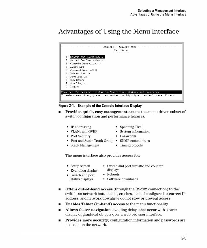
Figure 2-1. Example of the Console Interface Display
■ Provides quick, easy management access to a menu-driven subset of switch configuration and performance features:
• IP addressing • Spanning Tree • VLANs and GVRP • System information • Port Security • Passwords • Port and Static Trunk Group • SNMP communities • Stack Management • Time protocols
The menu interface also provides access for:
• Setup screen • Switch and port statistic and counter • Event Log display displays
• Switch and port • Rebootsstatus displays • Software downloads
■ Offers out-of-band access (through the RS-232 connection) to the switch, so network bottlenecks, crashes, lack of configured or correct IP address, and network downtime do not slow or prevent access
■ Enables Telnet (in-band) access to the menu functionality.
■ Allows faster navigation, avoiding delays that occur with slower display of graphical objects over a web browser interface.
■ Provides more security; configuration information and passwords are not seen on the network.
2-3
Selecting a Management Interface Advantages of Using the CLI
Advantages of Using the CLI
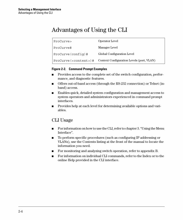
ProCurve> Operator Level
ProCurve# Manager Level
ProCurve(config)# Global Configuration Level
ProCurve(<context>)# Context Configuration Levels (port, VLAN)
Figure 2-2. Command Prompt Examples
■ Provides access to the complete set of the switch configuration, performance, and diagnostic features.
■ Offers out-of-band access (through the RS-232 connection) or Telnet (inband) access.
■ Enables quick, detailed system configuration and management access to system operators and administrators experienced in command prompt interfaces.
■ Provides help at each level for determining available options and variables.
CLI Usage
■ For information on how to use the CLI, refer to chapter 3. “Using the Menu Interface”.
■ To perform specific procedures (such as configuring IP addressing or VLANs), use the Contents listing at the front of the manual to locate the information you need.
■ For monitoring and analyzing switch operation, refer to appendix B.
■ For information on individual CLI commands, refer to the Index or to the online Help provided in the CLI interface.
2-4
Selecting a Management Interface Advantages of Using the Web Browser Interface
Advantages of Using the Web Browser Interface
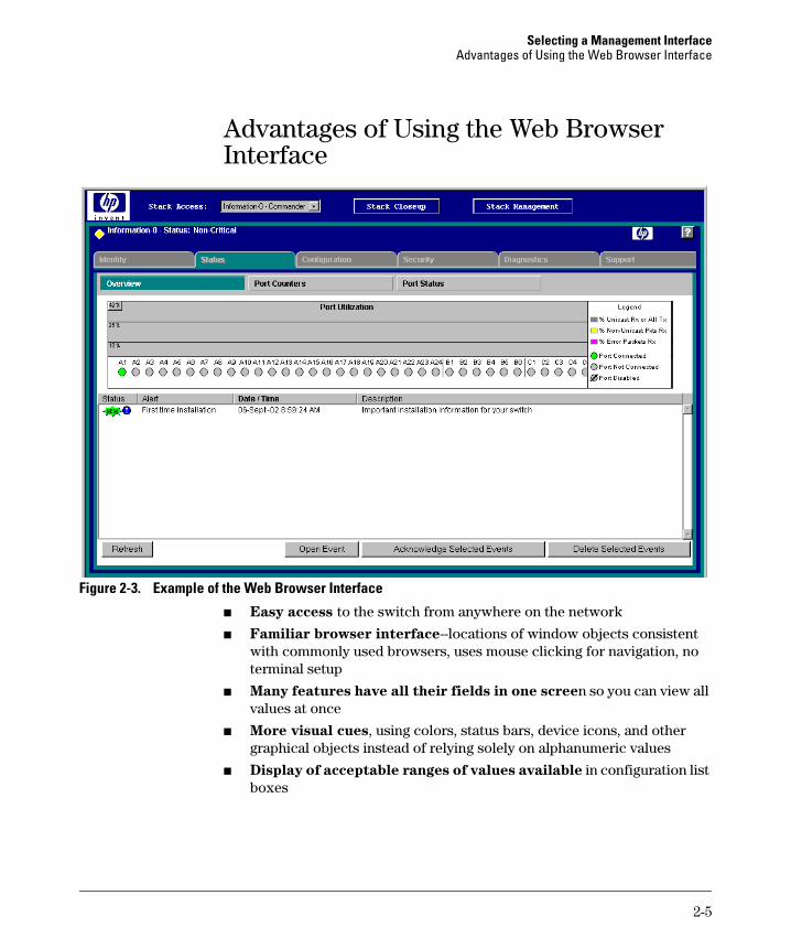
Figure 2-3. Example of the Web Browser Interface
■ Easy access to the switch from anywhere on the network
■ Familiar browser interface--locations of window objects consistent with commonly used browsers, uses mouse clicking for navigation, no terminal setup
■ Many features have all their fields in one screen so you can view all values at once
■ More visual cues, using colors, status bars, device icons, and other graphical objects instead of relying solely on alphanumeric values
■ Display of acceptable ranges of values available in configuration list boxes
2-5
Selecting a Management Interface Advantages of Using ProCurve Manager or ProCurve Manager Plus
Advantages of Using ProCurve Manager or ProCurve Manager Plus
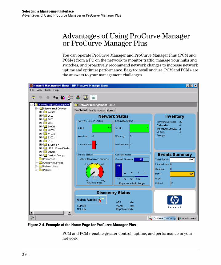
You can operate ProCurve Manager and ProCurve Manager Plus (PCM and PCM+) from a PC on the network to monitor traffic, manage your hubs and switches, and proactively recommend network changes to increase network uptime and optimize performance. Easy to install and use, PCM and PCM+ are the answers to your management challenges.
Figure 2-4. Example of the Home Page for ProCurve Manager Plus
PCM and PCM+ enable greater control, uptime, and performance in your network:
2-6
Selecting a Management Interface Advantages of Using ProCurve Manager or ProCurve Manager Plus
■ Features and benefits of ProCurve Manager:
• Network Status Summary: Upon boot-up, a network status screen displays high-level information on network devices, end nodes, events, and traffic levels. From here, users can research any one of these areas to get more details.
• Alerts and Troubleshooting: An events summary screen displays alerts to the user and categorizes them by severity, making it easier to track where bottlenecks and issues exist in the network. Alerts present detailed information on the problem, even down to the specific port.
• Automatic Device Discovery: This feature is customized for fast discovery of all ProCurve manageable network devices. The user can define which IP subnets to discover.
• Topology and Mapping: This feature automatically creates a map of discovered network devices. Maps are color-coded to reflect device status and can be viewed at multiple levels (physical view, subnet view, or VLAN view).
• Device Management: Many device-focused tasks can be performed directly by the software, or the user can access web-browser and command-line interfaces with the click of a button to manage individual devices from inside the tool.
■ Features and benefits of ProCurve Manager Plus:
• All of the Features of ProCurve Manager: Refer to the above listing.
• In-Depth Traffic Analysis: An integrated, low-overhead traffic monitor interface shows detailed information on traffic throughout the network. Using enhanced traffic analysis protocols such as Extended RMON and sFlow, users can monitor overall traffic levels, segments with the highest traffic, or even the top users within a network segment.
• Group and Policy Management: Changes in configuration are tracked and logged, and archived configurations can be applied to one or many devices. Configurations can be compared over time or between two devices, with the differences highlighted for users.
• Advanced VLAN Management: A new, easy-to-use VLAN management interface allows users to create and assign VLANs across the entire network, without having to access each network device individually.
2-7
Selecting a Management Interface Advantages of Using ProCurve Manager or ProCurve Manager Plus
• Device Software Updates: This feature automatically obtains new device software images from ProCurve and updates devices, allowing users to download the latest version or choose the desired version. Updates can be scheduled easily across large groups of devices, all at user-specified times.
• Investment Protection: The modular software architecture of ProCurve Manager Plus enables ProCurve to offer network administrators add-on software solutions that complement their needs.
2-8
3
Using the Menu Interface
Contents
Overview . . . . . . . . . . . . . . . . . . . . . . . . . . . . . . . . . . . . . . . . . . . . . . . . . . . . . . 3-2
Starting and Ending a Menu Session . . . . . . . . . . . . . . . . . . . . . . . . . . . . . . . 3-3
How To Start a Menu Interface Session . . . . . . . . . . . . . . . . . . . . . . . . . 3-4
How To End a Menu Session and Exit from the Console: . . . . . . . . . . 3-5
Main Menu Features . . . . . . . . . . . . . . . . . . . . . . . . . . . . . . . . . . . . . . . . . . . . . 3-7
Screen Structure and Navigation . . . . . . . . . . . . . . . . . . . . . . . . . . . . . . . . . . 3-9
Rebooting the Switch . . . . . . . . . . . . . . . . . . . . . . . . . . . . . . . . . . . . . . . . . . . 3-12
Menu Features List . . . . . . . . . . . . . . . . . . . . . . . . . . . . . . . . . . . . . . . . . . . . . 3-14
Where To Go From Here . . . . . . . . . . . . . . . . . . . . . . . . . . . . . . . . . . . . . . . . 3-15
3-1
Using the Menu Interface Overview
Overview This chapter describes the following:
■ Overview of the Menu Interface
■ Starting and ending a Menu session (page 3-3))
■ The Main Menu (page 3-7))
■ Screen structure and navigation (page 3-9))
■ Rebooting the switch (page 3-12))
The menu interface operates through the switch console to provide you with a subset of switch commands in an easy-to-use menu format enabling you to:
■ Perform a quick configuration of basic parameters, such as the IP addressing needed to provide management access through your network
■ Configure these features:
• Manager and Operator pass- • A network monitoring port words • Stack Management
• System parameters • Spanning Tree operation • IP addressing • SNMP community names • Time protocol • IP authorized managers • Ports • VLANs (Virtual LANs) and • Trunk groups GVRP
■ View status, counters, and Event Log information
■ Update switch software
■ Reboot the switch
For a detailed list of menu features, see the “Menu Features List” on page 3-14).
Privilege Levels and Password Security. ProCurve strongly recom
mends that you configure a Manager password to help prevent unauthorized
access to your network. A Manager password grants full read-write access to the switch. An Operator password, if configured, grants access to status and counter, Event Log, and the Operator level in the CLI. After you configure passwords on the switch and log off of the interface, access to the menu interface (and the CLI and web browser interface) will require entry of either the Manager or Operator password. (If the switch has only a Manager password, then someone without a password can still gain read-only access.)
3-2
Using the Menu Interface Starting and Ending a Menu Session
N o t e If the switch has neither a Manager nor an Operator password, anyone
having access to the console interface can operate the console with full
manager privileges. Also, if you configure only an Operator password,
entering the Operator password enables full manager privileges.
For more information on passwords, see the chapter on local passwords in the Access Security Guide for your switch.
■ The menu interface displays the current running-config parameter settings. You can use the menu interface to save configuration changes made in the CLI only if the CLI changes are in the running config when you save changes made in the menu interface. (For more on how switch memory manages configuration changes, see Chapter 6, “Switch Memory and Configuration”.)
■ A configuration change made through any switch interface overwrites earlier changes made through any other interface.
■ The Menu Interface and the CLI (Command Line Interface) both use the switch console. To enter the menu from the CLI, use the menu command. To enter the CLI from the Menu interface, select Command Line (CLI) option.)
Starting and Ending a Menu Session
You can access the menu interface using any of the following:
■ A direct serial connection to the switch’s console port, as described in the installation guide you received with the switch
■ A Telnet connection to the switch console from a networked PC or the switch’s web browser interface. Telnet requires that an IP address and subnet mask compatible with your network have already been configured on the switch.
■ The stack Commander, if the switch is a stack member
N o t e This section assumes that either a terminal device is already configured and connected to the switch (see the Installation and Getting Started Guide
shipped with your switch) or that you have already configured an IP address on the switch (required for Telnet access).
3-3
Using the Menu Interface Starting and Ending a Menu Session
How To Start a Menu Interface Session
In its factory default configuration, the switch console starts with the CLI prompt. To use the menu interface with Manager privileges, go to the Manager level prompt and enter the menu command.
1. Use one of these methods to connect to the switch:
• A PC terminal emulator or terminal
• Telnet
(You can also use the stack Commander if the switch is a stack member ).
2. Do one of the following:
• If you are using Telnet, go to step 3.
• If you are using a PC terminal emulator or a terminal, press [Enter] one or more times until a prompt appears.
3. When the switch screen appears, do one of the following:
• If a password has been configured, the password prompt appears.
Password: _
Type the Manager password and press [Enter]. Entering the Manager password gives you manager-level access to the switch. (Entering the Operator password gives you operator-level access to the switch. Refer to the chapter on local manager and operator usernames and passwords in the Access Security Guide for your switch.)
• If no password has been configured, the CLI prompt appears. Go to the next step.
4. When the CLI prompt appears, display the Menu interface by entering the menu command. For example:
ProCurve# menu [Enter]
results in:
3-4
Using the Menu Interface Starting and Ending a Menu Session
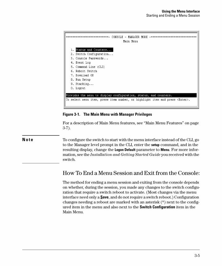
Figure 3-1. The Main Menu with Manager Privileges
For a description of Main Menu features, see “Main Menu Features” on page 3-7).
N o t e To configure the switch to start with the menu interface instead of the CLI, go to the Manager level prompt in the CLI, enter the setup command, and in the resulting display, change the Logon Default parameter to Menu. For more information, see the Installation and Getting Started Guide you received with the switch.
How To End a Menu Session and Exit from the Console:
The method for ending a menu session and exiting from the console depends on whether, during the session, you made any changes to the switch configuration that require a switch reboot to activate. (Most changes via the menu interface need only a Save, and do not require a switch reboot.) Configuration changes needing a reboot are marked with an asterisk (*) next to the configured item in the menu and also next to the Switch Configuration item in the Main Menu.
3-5
Using the Menu Interface Starting and Ending a Menu Session
ii
ito activate.
Aster sk indicates a configurat on change that requ res a reboot
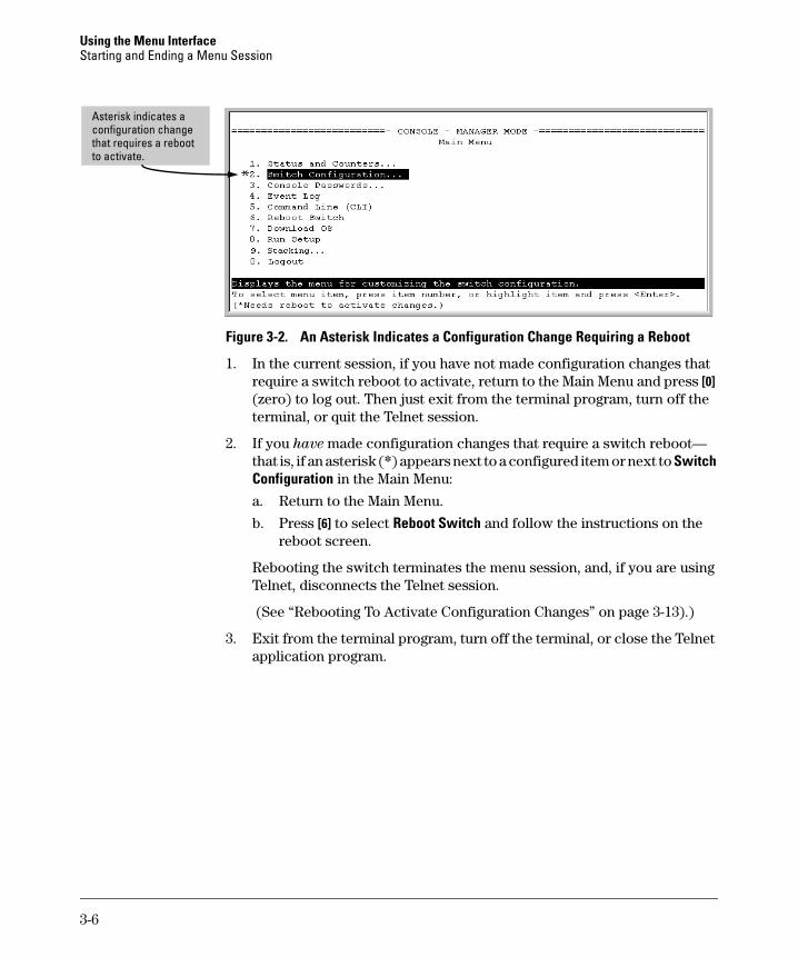
Figure 3-2. An Asterisk Indicates a Configuration Change Requiring a Reboot
1. In the current session, if you have not made configuration changes that require a switch reboot to activate, return to the Main Menu and press [0] (zero) to log out. Then just exit from the terminal program, turn off the terminal, or quit the Telnet session.
2. If you have made configuration changes that require a switch reboot— that is, if an asterisk (*) appears next to a configured item or next to Switch Configuration in the Main Menu:
a. Return to the Main Menu.
b. Press [6] to select Reboot Switch and follow the instructions on the reboot screen.
Rebooting the switch terminates the menu session, and, if you are using Telnet, disconnects the Telnet session.
(See “Rebooting To Activate Configuration Changes” on page 3-13).)
3. Exit from the terminal program, turn off the terminal, or close the Telnet application program.
3-6
Using the Menu Interface Main Menu Features
Main Menu Features
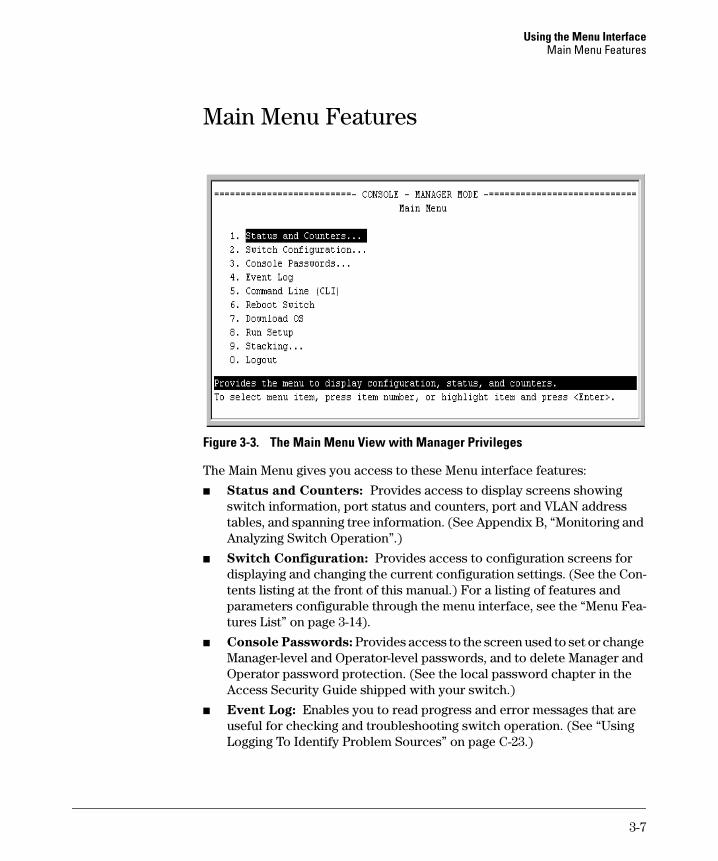
Figure 3-3. The Main Menu View with Manager Privileges
The Main Menu gives you access to these Menu interface features:
■ Status and Counters: Provides access to display screens showing switch information, port status and counters, port and VLAN address tables, and spanning tree information. (See Appendix B, “Monitoring and Analyzing Switch Operation”.)
■ Switch Configuration: Provides access to configuration screens for displaying and changing the current configuration settings. (See the Contents listing at the front of this manual.) For a listing of features and parameters configurable through the menu interface, see the “Menu Features List” on page 3-14).
■ Console Passwords: Provides access to the screen used to set or change Manager-level and Operator-level passwords, and to delete Manager and Operator password protection. (See the local password chapter in the Access Security Guide shipped with your switch.)
■ Event Log: Enables you to read progress and error messages that are useful for checking and troubleshooting switch operation. (See “Using Logging To Identify Problem Sources” on page C-23.)
3-7
Using the Menu Interface Main Menu Features
■ Command Line (CLI): Selects the Command Line Interface at the same level (Manager or Operator) that you are accessing in the Menu interface. (See chapter 4, “Using the Command Line Interface (CLI)”.)
■ Reboot Switch: Performs a “warm” reboot of the switch, which clears most temporary error conditions, resets the network activity counters to zero, and resets the system up-time to zero. A reboot is required to activate a change in the VLAN Support parameter. (See “Rebooting from the Menu Interface” on page 6-10.)
■ Download OS: Enables you to download a new software version to the switch. (See Appendix A, “File Transfers”.)
■ Run Setup: Displays the Switch Setup screen for quickly configuring basic switch parameters such as IP addressing, default gateway, logon default interface, spanning tree, and others. (See the Installation and
Getting Started guide shipped with your switch.)
■ Stacking: Enables you to use a single IP address and standard network cabling to manage a group of up to 16 switches in the same subnet (broadcast domain). See the chapter on stack management in the Advanced Traffic Management Guide.
■ Logout: Closes the Menu interface and console session, and disconnects Telnet access to the switch. (See “How to End a Menu Session and Exit from the Console” on page 3-5).)
3-8
Using the Menu Interface Screen Structure and Navigation
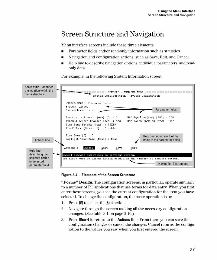
Screen Structure and Navigation Menu interface screens include these three elements:
■ Parameter fields and/or read-only information such as statistics
■ Navigation and configuration actions, such as Save, Edit, and Cancel
■ Help line to describe navigation options, individual parameters, and read-only data
For example, in the following System Information screen:
items i l
i
Screen title – identifies the location within the
Help line describing the selected action or selected parameter field
Parameter fields
Help describing each of the n the parameter fie ds
Navigation nstructions
Actions line
menu structure
Figure 3-4. Elements of the Screen Structure
“Forms” Design. The configuration screens, in particular, operate similarly to a number of PC applications that use forms for data entry. When you first enter these screens, you see the current configuration for the item you have selected. To change the configuration, the basic operation is to:
1. Press [E] to select the Edit action.
2. Navigate through the screen making all the necessary configuration changes. (See table 3-1 on page 3-10.)
3. Press [Enter] to return to the Actions line. From there you can save the configuration changes or cancel the changes. Cancel returns the configuration to the values you saw when you first entered the screen.
3-9
Using the Menu Interface Screen Structure and Navigation
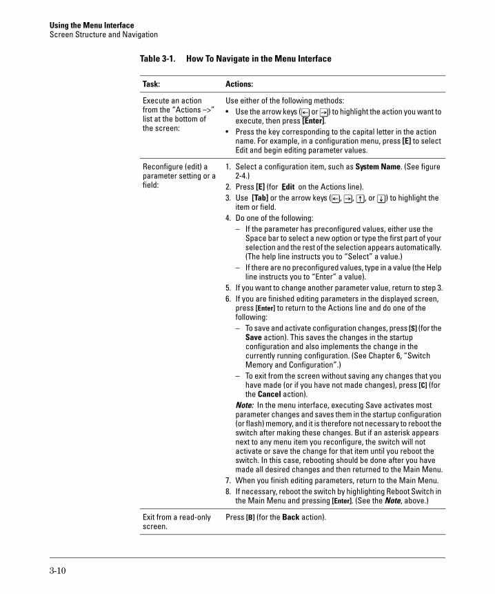
Table 3-1. How To Navigate in the Menu Interface
Task: Actions:
Execute an action Use either of the following methods:from the “Actions –>” • Use the arrow keys ([<] or [>]) to highlight the action you want to list at the bottom of execute, then press [Enter].the screen: • Press the key corresponding to the capital letter in the action
name. For example, in a configuration menu, press [E] to select Edit and begin editing parameter values.
Reconfigure (edit) a parameter setting or a field:
1. Select a configuration item, such as System Name. (See figure 2-4.)
2. Press [E] (for Edit on the Actions line). 3. Use [Tab] or the arrow keys ([<], [>], [^], or [v]) to highlight the
item or field. 4. Do one of the following:
– If the parameter has preconfigured values, either use the Space bar to select a new option or type the first part of your selection and the rest of the selection appears automatically. (The help line instructs you to “Select” a value.)
– If there are no preconfigured values, type in a value (the Help line instructs you to “Enter” a value).
5. If you want to change another parameter value, return to step 3. 6. If you are finished editing parameters in the displayed screen,
press [Enter] to return to the Actions line and do one of the following: – To save and activate configuration changes, press [S] (for the
Save action). This saves the changes in the startup configuration and also implements the change in the currently running configuration. (See Chapter 6, “Switch Memory and Configuration”.)
– To exit from the screen without saving any changes that you have made (or if you have not made changes), press [C] (for the Cancel action).
Note: In the menu interface, executing Save activates most parameter changes and saves them in the startup configuration (or flash) memory, and it is therefore not necessary to reboot the switch after making these changes. But if an asterisk appears next to any menu item you reconfigure, the switch will not activate or save the change for that item until you reboot the switch. In this case, rebooting should be done after you have made all desired changes and then returned to the Main Menu.
7. When you finish editing parameters, return to the Main Menu. 8. If necessary, reboot the switch by highlighting Reboot Switch in
the Main Menu and pressing [Enter]. (See the Note, above.)
Exit from a read-only Press [B] (for the Back action). screen.
3-10
Using the Menu Interface Screen Structure and Navigation
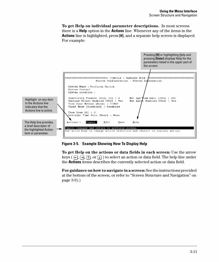
To get Help on individual parameter descriptions. In most screens there is a Help option in the Actions line. Whenever any of the items in the Actions line is highlighted, press [H], and a separate help screen is displayed. For example:
[H] i] di
Hi
i i
l
li
Pressing or h ghlighting Help and pressing [Enter splays Help for the parameters listed in the upper part of the screen
ghlight on any item in the Actions line nd cates that the
Actions line is active.
The He p line provides a brief descriptor of the high ghted Action item or parameter.
Figure 3-5. Example Showing How To Display Help
To get Help on the actions or data fields in each screen: Use the arrow keys ( [<], [>], [^], or [v] ) to select an action or data field. The help line under the Actions items describes the currently selected action or data field.
For guidance on how to navigate in a screen: See the instructions provided at the bottom of the screen, or refer to “Screen Structure and Navigation” on page 3-9).)
3-11
Using the Menu Interface Rebooting the Switch
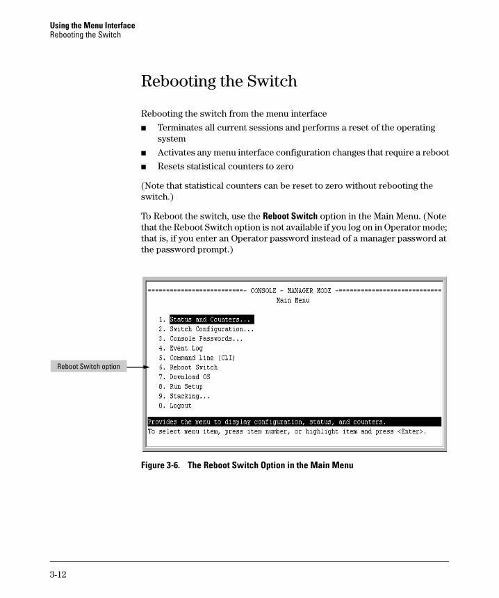
Rebooting the Switch
Rebooting the switch from the menu interface
■ Terminates all current sessions and performs a reset of the operating system
■ Activates any menu interface configuration changes that require a reboot
■ Resets statistical counters to zero
(Note that statistical counters can be reset to zero without rebooting the switch.)
To Reboot the switch, use the Reboot Switch option in the Main Menu. (Note that the Reboot Switch option is not available if you log on in Operator mode; that is, if you enter an Operator password instead of a manager password at the password prompt.)
Reboot Switch option
Figure 3-6. The Reboot Switch Option in the Main Menu
3-12
Using the Menu Interface Rebooting the Switch
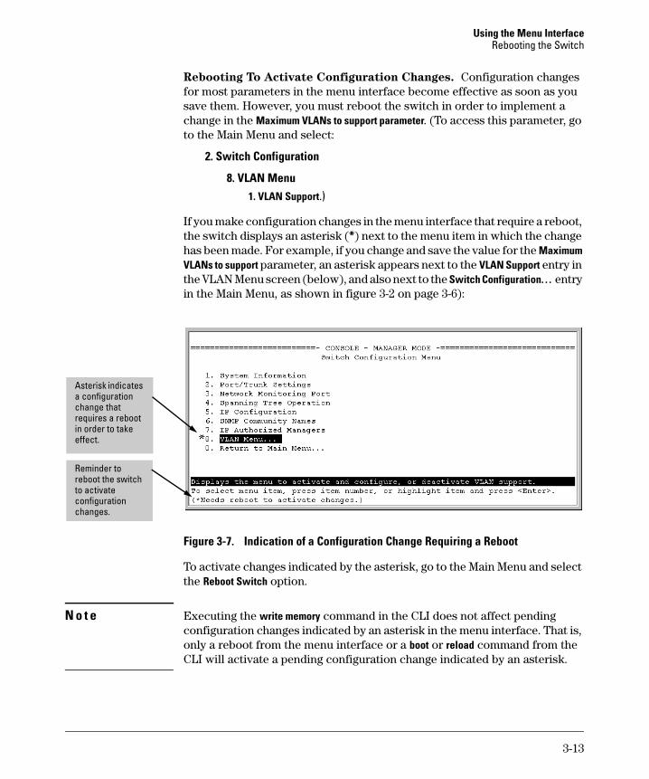
Rebooting To Activate Configuration Changes. Configuration changes for most parameters in the menu interface become effective as soon as you save them. However, you must reboot the switch in order to implement a change in the Maximum VLANs to support parameter. (To access this parameter, go to the Main Menu and select:
2. Switch Configuration
8. VLAN Menu1. VLAN Support.)
If you make configuration changes in the menu interface that require a reboot, the switch displays an asterisk (*) next to the menu item in which the change has been made. For example, if you change and save the value for the Maximum VLANs to support parameter, an asterisk appears next to the VLAN Support entry in the VLAN Menu screen (below), and also next to the Switch Configuration. . . entry in the Main Menu, as shown in figure 3-2 on page 3-6):
i
Asteri
effect.
Reminder to reboot the switch to act vate configuration changes.
sk indicates a configuration change that requires a reboot in order to take
Figure 3-7. Indication of a Configuration Change Requiring a Reboot
To activate changes indicated by the asterisk, go to the Main Menu and select the Reboot Switch option.
N o t e Executing the write memory command in the CLI does not affect pending configuration changes indicated by an asterisk in the menu interface. That is, only a reboot from the menu interface or a boot or reload command from the CLI will activate a pending configuration change indicated by an asterisk.
3-13
Using the Menu Interface Menu Features List
Menu Features List
Status and Counters
• General System Information
• Switch Management Address Information
• Port Status
• Port Counters
• Address Table
• Port Address Table
• Spanning Tree Information
Switch Configuration
• System Information
• Port/Trunk Settings
• Network Monitoring Port
• Spanning Tree Operation
• IP Configuration
• SNMP Community Names
• IP authorized Managers
• VLAN Menu
Console Passwords
Event Log
Command Line (CLI)
Reboot Switch
Download OS
Run Setup
Stacking
• Stacking Status (This Switch)
• Stacking Status (All)
• Stack Configuration
• Stack Management (Available in Stack Commander Only)
• Stack Access (Available in Stack Commander Only)
Logout
3-14
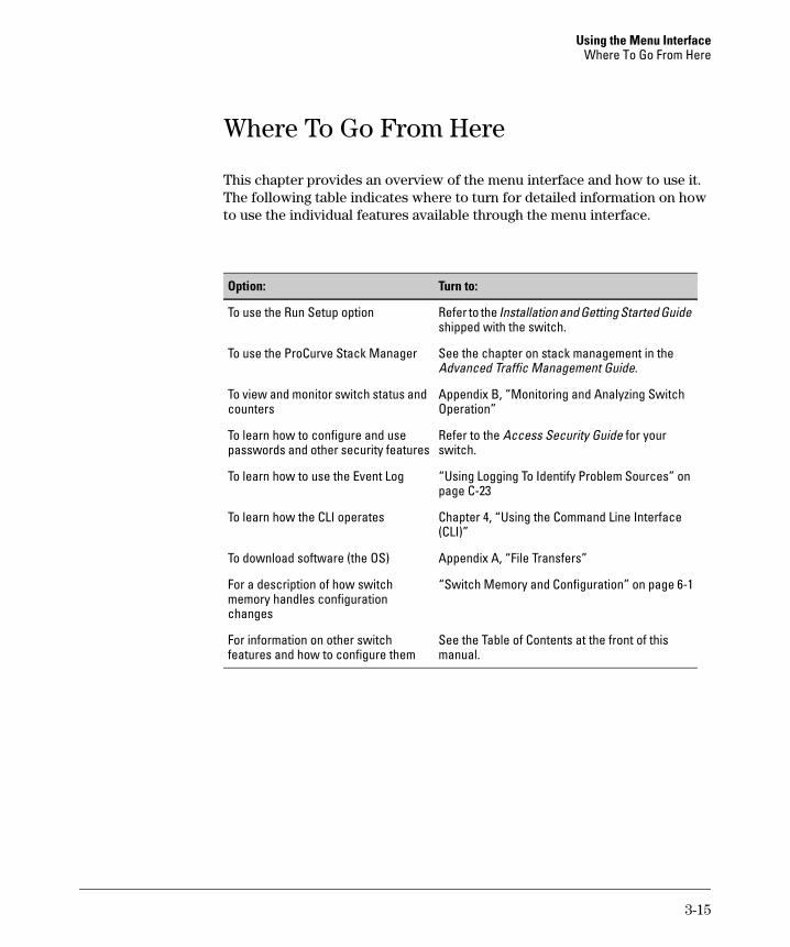
Using the Menu Interface Where To Go From Here
Where To Go From Here
This chapter provides an overview of the menu interface and how to use it. The following table indicates where to turn for detailed information on how to use the individual features available through the menu interface.
Option: Turn to:
To use the Run Setup option
To use the ProCurve Stack Manager
To view and monitor switch status and counters
To learn how to configure and use passwords and other security features
To learn how to use the Event Log
To learn how the CLI operates
To download software (the OS)
For a description of how switch memory handles configuration changes
For information on other switch features and how to configure them
Refer to the Installation and Getting Started Guide shipped with the switch.
See the chapter on stack management in the Advanced Traffic Management Guide.
Appendix B, “Monitoring and Analyzing Switch Operation”
Refer to the Access Security Guide for your switch.
“Using Logging To Identify Problem Sources” on page C-23
Chapter 4, “Using the Command Line Interface (CLI)”
Appendix A, “File Transfers”
“Switch Memory and Configuration” on page 6-1
See the Table of Contents at the front of this manual.
3-15

Using the Menu Interface Where To Go From Here
— This page is intentionally unused. —
3-16
4
Using the Command Line Interface (CLI)
Contents
Overview . . . . . . . . . . . . . . . . . . . . . . . . . . . . . . . . . . . . . . . . . . . . . . . . . . . . . . 4-2
Accessing the CLI . . . . . . . . . . . . . . . . . . . . . . . . . . . . . . . . . . . . . . . . . . . . . . . 4-2
Using the CLI . . . . . . . . . . . . . . . . . . . . . . . . . . . . . . . . . . . . . . . . . . . . . . . . . . . 4-2
Privilege Levels at Logon . . . . . . . . . . . . . . . . . . . . . . . . . . . . . . . . . . . . . 4-3
Privilege Level Operation . . . . . . . . . . . . . . . . . . . . . . . . . . . . . . . . . . . . . 4-4Operator Privileges . . . . . . . . . . . . . . . . . . . . . . . . . . . . . . . . . . . . . . 4-4Manager Privileges . . . . . . . . . . . . . . . . . . . . . . . . . . . . . . . . . . . . . . . 4-5
How To Move Between Levels . . . . . . . . . . . . . . . . . . . . . . . . . . . . . . . . 4-7
Listing Commands and Command Options . . . . . . . . . . . . . . . . . . . . . . 4-8Listing Commands Available at Any Privilege Level . . . . . . . . . . . 4-8Command Option Displays . . . . . . . . . . . . . . . . . . . . . . . . . . . . . . . 4-10
Displaying CLI "Help" . . . . . . . . . . . . . . . . . . . . . . . . . . . . . . . . . . . . . . . 4-11
Configuration Commands and the Context Configuration Modes . . 4-13
CLI Control and Editing . . . . . . . . . . . . . . . . . . . . . . . . . . . . . . . . . . . . . . . . . 4-16
4-1
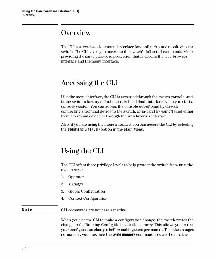
Using the Command Line Interface (CLI) Overview
Overview
The CLI is a text-based command interface for configuring and monitoring the switch. The CLI gives you access to the switch’s full set of commands while providing the same password protection that is used in the web browser interface and the menu interface.
Accessing the CLI
Like the menu interface, the CLI is accessed through the switch console, and, in the switch’s factory default state, is the default interface when you start a console session. You can access the console out-of-band by directly connecting a terminal device to the switch, or in-band by using Telnet either from a terminal device or through the web browser interface.
Also, if you are using the menu interface, you can access the CLI by selecting the Command Line (CLI) option in the Main Menu.
Using the CLI
The CLI offers these privilege levels to help protect the switch from unauthorized access:
1. Operator
2. Manager
3. Global Configuration
4. Context Configuration
N o t e CLI commands are not case-sensitive.
When you use the CLI to make a configuration change, the switch writes the change to the Running-Config file in volatile memory. This allows you to test your configuration changes before making them permanent. To make changes permanent, you must use the write memory command to save them to the
4-2
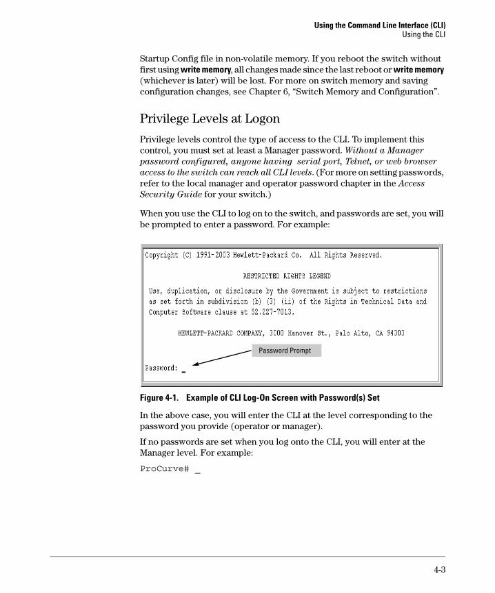
Using the Command Line Interface (CLI) Using the CLI
Startup Config file in non-volatile memory. If you reboot the switch without first using write memory, all changes made since the last reboot or write memory (whichever is later) will be lost. For more on switch memory and saving configuration changes, see Chapter 6, “Switch Memory and Configuration”.
Privilege Levels at Logon
Privilege levels control the type of access to the CLI. To implement this control, you must set at least a Manager password. Without a Manager
password configured, anyone having serial port, Telnet, or web browser
access to the switch can reach all CLI levels. (For more on setting passwords, refer to the local manager and operator password chapter in the Access
Security Guide for your switch.)
When you use the CLI to log on to the switch, and passwords are set, you will be prompted to enter a password. For example:
Password Prompt
Figure 4-1. Example of CLI Log-On Screen with Password(s) Set
In the above case, you will enter the CLI at the level corresponding to the password you provide (operator or manager).
If no passwords are set when you log onto the CLI, you will enter at the Manager level. For example:
ProCurve# _
4-3
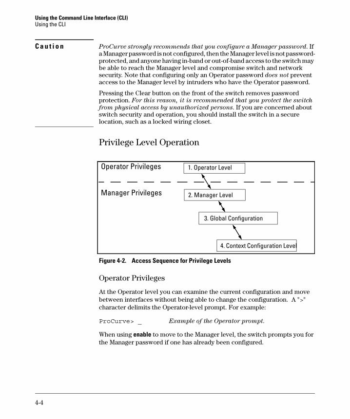
Using the Command Line Interface (CLI) Using the CLI
C a u t i o n ProCurve strongly recommends that you configure a Manager password. If a Manager password is not configured, then the Manager level is not password-protected, and anyone having in-band or out-of-band access to the switch may be able to reach the Manager level and compromise switch and network security. Note that configuring only an Operator password does not prevent access to the Manager level by intruders who have the Operator password.
Pressing the Clear button on the front of the switch removes password protection. For this reason, it is recommended that you protect the switch
from physical access by unauthorized persons. If you are concerned about switch security and operation, you should install the switch in a secure location, such as a locked wiring closet.
Privilege Level Operation
Operator Privileges
Manager Privileges
1. Operator Level
2. Manager Level
3. Global Configuration
4. Context Configuration Level
Figure 4-2. Access Sequence for Privilege Levels
Operator Privileges
At the Operator level you can examine the current configuration and move between interfaces without being able to change the configuration. A ">" character delimits the Operator-level prompt. For example:
ProCurve> _ Example of the Operator prompt.
When using enable to move to the Manager level, the switch prompts you for the Manager password if one has already been configured.
4-4
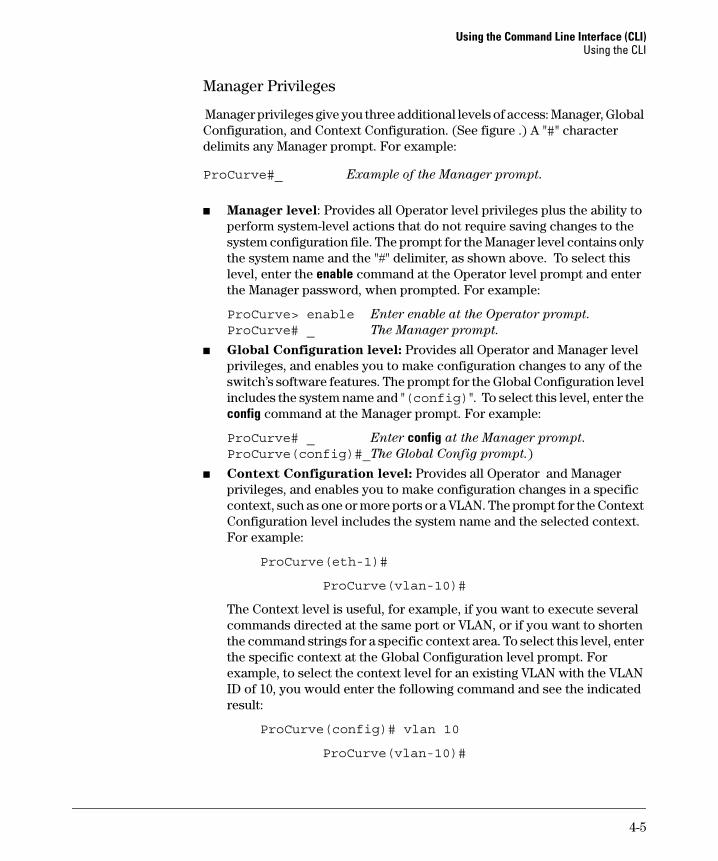
Using the Command Line Interface (CLI) Using the CLI
Manager Privileges
Manager privileges give you three additional levels of access: Manager, Global Configuration, and Context Configuration. (See figure .) A "#" character delimits any Manager prompt. For example:
ProCurve#_ Example of the Manager prompt.
■ Manager level: Provides all Operator level privileges plus the ability to perform system-level actions that do not require saving changes to the system configuration file. The prompt for the Manager level contains only the system name and the "#" delimiter, as shown above. To select this level, enter the enable command at the Operator level prompt and enter the Manager password, when prompted. For example:
ProCurve> enable Enter enable at the Operator prompt. ProCurve# _ The Manager prompt.
■ Global Configuration level: Provides all Operator and Manager level privileges, and enables you to make configuration changes to any of the switch’s software features. The prompt for the Global Configuration level includes the system name and "(config)". To select this level, enter the config command at the Manager prompt. For example:
ProCurve# _ Enter config at the Manager prompt. ProCurve(config)#_The Global Config prompt.)
■ Context Configuration level: Provides all Operator and Manager privileges, and enables you to make configuration changes in a specific context, such as one or more ports or a VLAN. The prompt for the Context Configuration level includes the system name and the selected context. For example:
ProCurve(eth-1)#
ProCurve(vlan-10)#
The Context level is useful, for example, if you want to execute several commands directed at the same port or VLAN, or if you want to shorten the command strings for a specific context area. To select this level, enter the specific context at the Global Configuration level prompt. For example, to select the context level for an existing VLAN with the VLAN ID of 10, you would enter the following command and see the indicated result:
ProCurve(config)# vlan 10
ProCurve(vlan-10)#
4-5
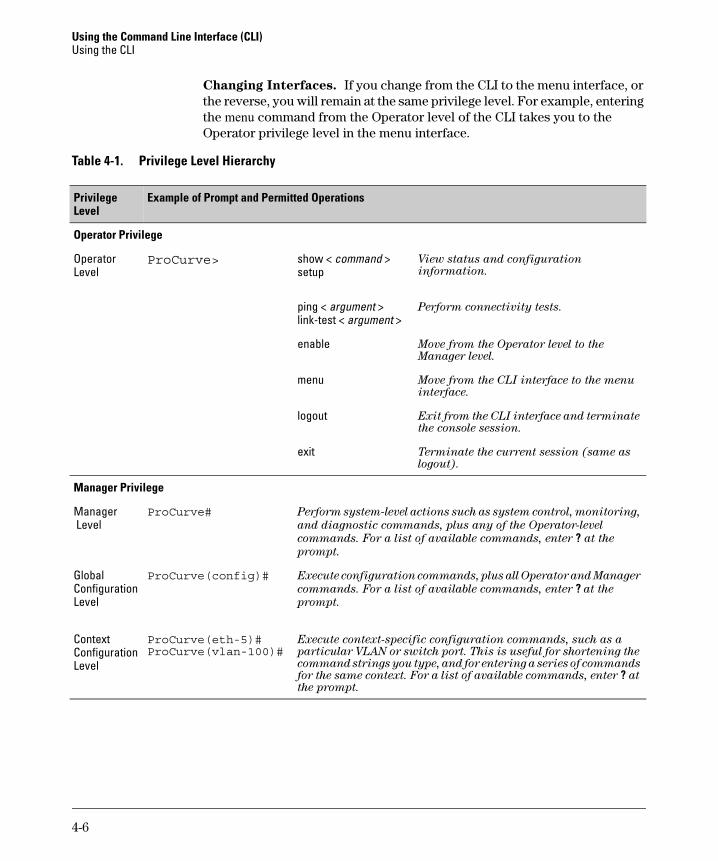
Using the Command Line Interface (CLI) Using the CLI
Changing Interfaces. If you change from the CLI to the menu interface, or the reverse, you will remain at the same privilege level. For example, entering the menu command from the Operator level of the CLI takes you to the Operator privilege level in the menu interface.
Table 4-1. Privilege Level Hierarchy
Privilege Level
Example of Prompt and Permitted Operations
Operator Privilege
Operator ProCurve> show < command > View status and configuration
Level setup information.
ping < argument > Perform connectivity tests.
link-test < argument >
enable Move from the Operator level to the Manager level.
menu Move from the CLI interface to the menu interface.
logout Exit from the CLI interface and terminate the console session.
exit Terminate the current session (same as logout).
Manager Privilege
Manager ProCurve# Perform system-level actions such as system control, monitoring,
Level and diagnostic commands, plus any of the Operator-level
commands. For a list of available commands, enter ? at the
prompt.
Global ProCurve(config)# Execute configuration commands, plus all Operator and Manager
Configuration commands. For a list of available commands, enter ? at the
Level prompt.
Context ProCurve(eth-5)# Execute context-specific configuration commands, such as a
Configuration ProCurve(vlan-100)# particular VLAN or switch port. This is useful for shortening the
Level command strings you type, and for entering a series of commands for the same context. For a list of available commands, enter ? at the prompt.
4-6
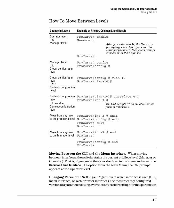
Using the Command Line Interface (CLI) Using the CLI
How To Move Between Levels
Change in Levels Example of Prompt, Command, and Result
Operator level to
Manager level
Manager level to
Global configuration level
Global configuration level
to a Context configuration level
Context configuration level
to another Context configuration level
Move from any level to the preceding level
Move from any level to the Manager level
ProCurve> enablePassword:_
After you enter enable, the Password prompt appears. After you enter the Manager password, the system prompt appears with the # symbol:
ProCurve#_
ProCurve# configProCurve(config)#
ProCurve(config)# vlan 10ProCurve(vlan-10)#
ProCurve(vlan-10)# interface e 3ProCurve(int-3)#
The CLI accepts "e" as the abbreviated form of "ethernet".
ProCurve(int-3)# exitProCurve(config)# exitProCurve# exitProCurve>
ProCurve(int-3)# endProCurve#
—or— ProCurve(config)# end ProCurve#
Moving Between the CLI and the Menu Interface. When moving between interfaces, the switch retains the current privilege level (Manager or Operator). That is, if you are at the Operator level in the menu and select the Command Line Interface (CLI) option from the Main Menu, the CLI prompt appears at the Operator level.
Changing Parameter Settings. Regardless of which interface is used (CLI, menu interface, or web browser interface), the most recently configured version of a parameter setting overrides any earlier settings for that parameter.
4-7
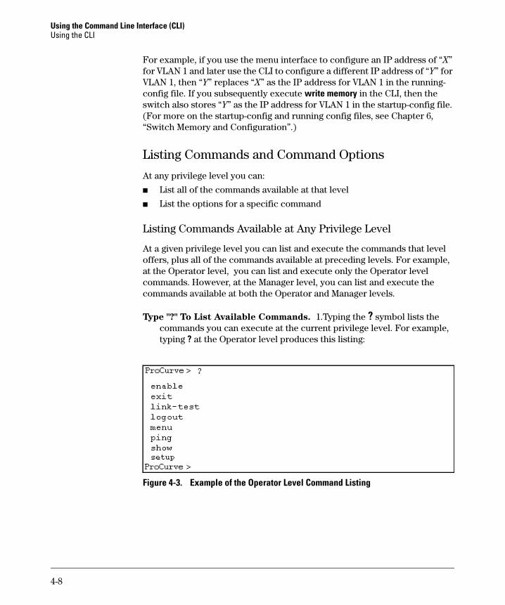
Using the Command Line Interface (CLI) Using the CLI
For example, if you use the menu interface to configure an IP address of “X” for VLAN 1 and later use the CLI to configure a different IP address of “Y” for VLAN 1, then “Y” replaces “X” as the IP address for VLAN 1 in the runningconfig file. If you subsequently execute write memory in the CLI, then the switch also stores “Y” as the IP address for VLAN 1 in the startup-config file. (For more on the startup-config and running config files, see Chapter 6, “Switch Memory and Configuration”.)
Listing Commands and Command Options
At any privilege level you can:
■ List all of the commands available at that level
■ List the options for a specific command
Listing Commands Available at Any Privilege Level
At a given privilege level you can list and execute the commands that level offers, plus all of the commands available at preceding levels. For example, at the Operator level, you can list and execute only the Operator level commands. However, at the Manager level, you can list and execute the commands available at both the Operator and Manager levels.
Type "?" To List Available Commands. 1.Typing the ? symbol lists the commands you can execute at the current privilege level. For example, typing ? at the Operator level produces this listing:
Figure 4-3. Example of the Operator Level Command Listing
4-8
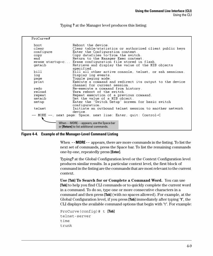
Using the Command Line Interface (CLI) Using the CLI
Typing ? at the Manager level produces this listing:
or When - - MORE - - appears, use the Space bar
[Return] to list additional commands.
Figure 4-4. Example of the Manager-Level Command Listing
When - - MORE - - appears, there are more commands in the listing. To list the next set of commands, press the Space bar. To list the remaining commands one-by-one, repeatedly press [Enter].
Typing? at the Global Configuration level or the Context Configuration level produces similar results. In a particular context level, the first block of command in the listing are the commands that are most relevant to the current context.
Use [Tab] To Search for or Complete a Command Word. You can use [Tab] to help you find CLI commands or to quickly complete the current word in a command. To do so, type one or more consecutive characters in a command and then press [Tab] (with no spaces allowed). For example, at the Global Configuration level, if you press [Tab] immediately after typing "t", the CLI displays the available command options that begin with "t". For example:
ProCurve(config)# t [Tab] telnet-server time trunk
4-9
Using the Command Line Interface (CLI) Using the CLI
telnetterminalProCurve(config)# t
As mentioned above, if you type part of a command word and press [Tab], the CLI completes the current word (if you have typed enough of the word for the CLI to distinguish it from other possibilities), including hyphenated extensions. For example:
ProCurve(config)# port [Tab] ProCurve(config)# port-security _
Pressing [Tab] after a completed command word lists the further options for that command.
ProCurve(config)# stack [Tab] commander <commander-str> join <mac-addr> auto-join transmission-interval <integer> <cr> ProCurve(config)# stack
Command Option Displays
Conventions for Command Option Displays. When you use the CLI to list options for a particular command, you will see one or more of the following conventions to help you interpret the command data:
■ Braces (< >) indicate a required choice.
■ Square brackets ([]) indicate optional elements.
■ Vertical bars (|) separate alternative, mutually exclusive options in a command.
4-10
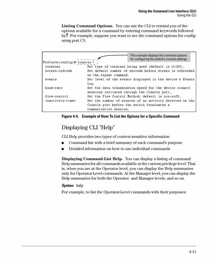
Using the Command Line Interface (CLI) Using the CLI
Listing Command Options. You can use the CLI to remind you of the options available for a command by entering command keywords followed by?. For example, suppose you want to see the command options for configuring port C5:
i lThis example displays the command options for configur ng the switch’s conso e settings.
Figure 4-5. Example of How To List the Options for a Specific Command
Displaying CLI "Help"
CLI Help provides two types of context-sensitive information:
■ Command list with a brief summary of each command’s purpose
■ Detailed information on how to use individual commands
Displaying Command-List Help. You can display a listing of command Help summaries for all commands available at the current privilege level. That is, when you are at the Operator level, you can display the Help summaries only for Operator-Level commands. At the Manager level, you can display the Help summaries for both the Operator and Manager levels, and so on.
Syntax: help
For example, to list the Operator-Level commands with their purposes:
4-11
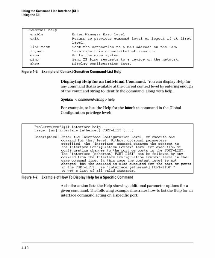
Using the Command Line Interface (CLI) Using the CLI
Figure 4-6. Example of Context-Sensitive Command-List Help
Displaying Help for an Individual Command. You can display Help for any command that is available at the current context level by entering enough of the command string to identify the command, along with help.
Syntax: < command-string > help
For example, to list the Help for the interface command in the Global Configuration privilege level:
Figure 4-7. Example of How To Display Help for a Specific Command
A similar action lists the Help showing additional parameter options for a given command. The following example illustrates how to list the Help for an interface command acting on a specific port:
4-12
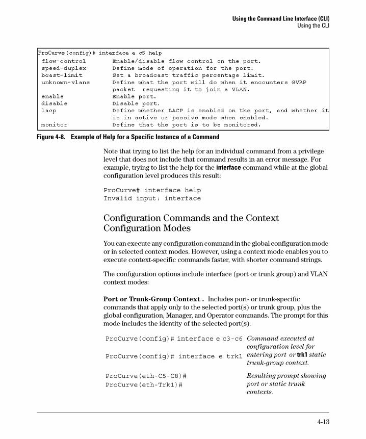
Using the Command Line Interface (CLI) Using the CLI
Figure 4-8. Example of Help for a Specific Instance of a Command
Note that trying to list the help for an individual command from a privilege level that does not include that command results in an error message. For example, trying to list the help for the interface command while at the global configuration level produces this result:
ProCurve# interface helpInvalid input: interface
Configuration Commands and the Context Configuration Modes
You can execute any configuration command in the global configuration mode or in selected context modes. However, using a context mode enables you to execute context-specific commands faster, with shorter command strings.
The configuration options include interface (port or trunk group) and VLAN context modes:
Port or Trunk-Group Context . Includes port- or trunk-specific commands that apply only to the selected port(s) or trunk group, plus the global configuration, Manager, and Operator commands. The prompt for this mode includes the identity of the selected port(s):
ProCurve(config)# interface e c3-c6 Command executed at
configuration level for
ProCurve(config)# interface e trk1 entering port or trk1 static
trunk-group context.
ProCurve(eth-C5-C8)# Resulting prompt showing
ProCurve(eth-Trk1)# port or static trunk
contexts.
4-13
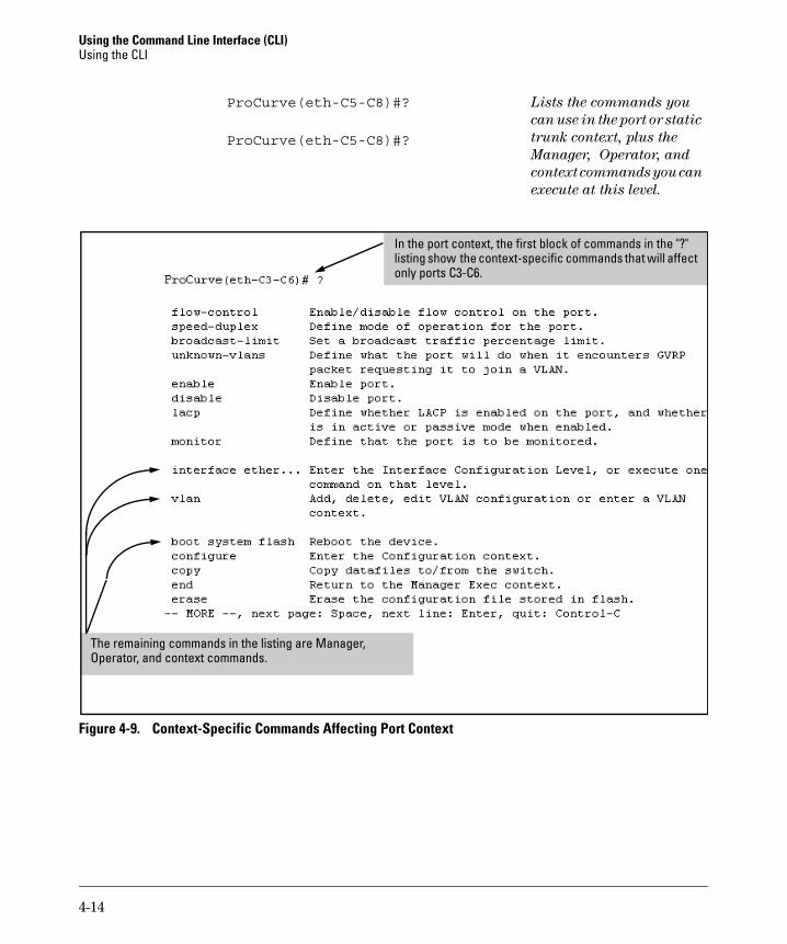
Using the Command Line Interface (CLI) Using the CLI
ProCurve(eth-C5-C8)#? Lists the commands you
can use in the port or static
ProCurve(eth-C5-C8)#? trunk context, plus the
Manager, Operator, and
context commands you can
execute at this level.
listing show only ports C3-C6.
In the port context, the first block of commands in the "?" the context-specific commands that will affect
The remaining commands in the listing are Manager, Operator, and context commands.
Figure 4-9. Context-Specific Commands Affecting Port Context
4-14
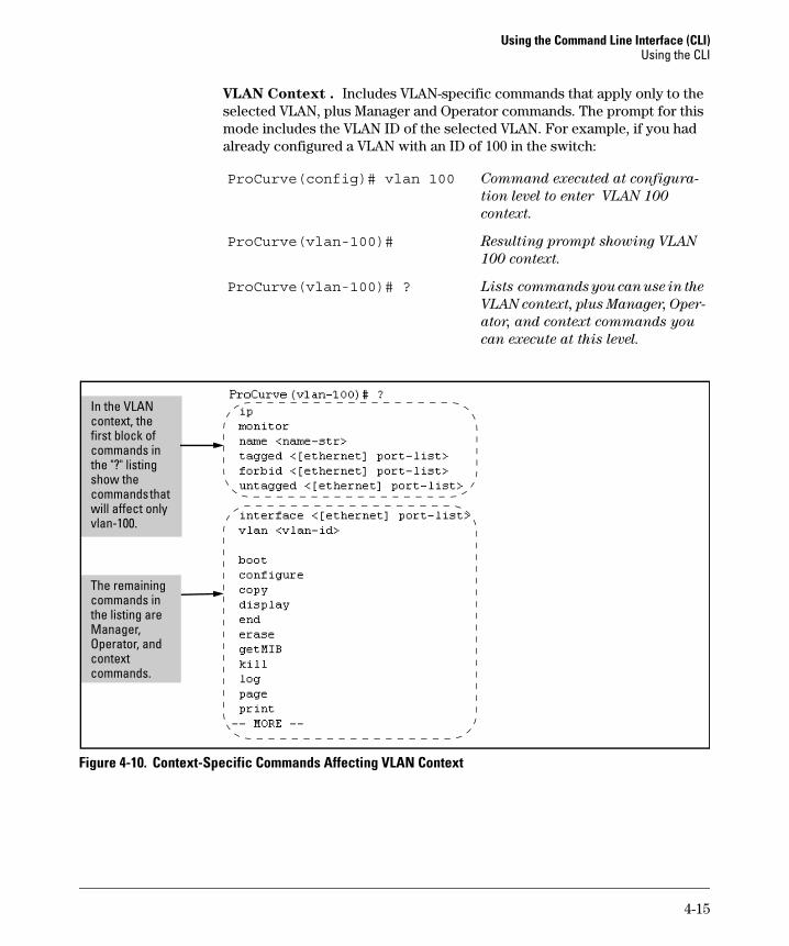
Using the Command Line Interface (CLI) Using the CLI
VLAN Context . Includes VLAN-specific commands that apply only to the selected VLAN, plus Manager and Operator commands. The prompt for this mode includes the VLAN ID of the selected VLAN. For example, if you had already configured a VLAN with an ID of 100 in the switch:
ProCurve(config)# vlan 100 Command executed at configura
tion level to enter VLAN 100
context.
ProCurve(vlan-100)# Resulting prompt showing VLAN
100 context.
ProCurve(vlan-100)# ? Lists commands you can use in the
VLAN context, plus Manager, Oper
ator, and context commands you
can execute at this level.
In the VLAN context, the first blcommands in
show the commands that
vl
The remaining commands in
context commands.
ock of
the "?" listing
will affect only an-100.
the listing are Manager, Operator, and
Figure 4-10. Context-Specific Commands Affecting VLAN Context
4-15
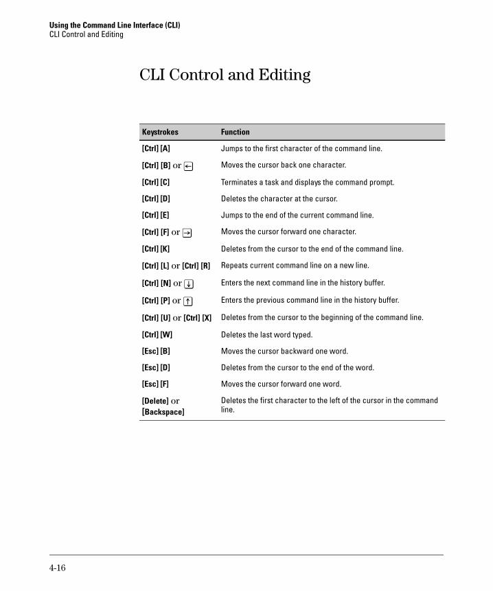
Using the Command Line Interface (CLI) CLI Control and Editing
CLI Control and Editing
FunctionKeystrokes
[Ctrl] [A]
[Ctrl] [B] or [<]
[Ctrl] [C]
[Ctrl] [D]
[Ctrl] [E]
[Ctrl] [F] or [>]
[Ctrl] [K]
[Ctrl] [L] or [Ctrl] [R]
[Ctrl] [N] or [v]
[Ctrl] [P] or [^]
[Ctrl] [U] or [Ctrl] [X]
[Ctrl] [W]
[Esc] [B]
[Esc] [D]
[Esc] [F]
[Delete] or[Backspace]
Jumps to the first character of the command line.
Moves the cursor back one character.
Terminates a task and displays the command prompt.
Deletes the character at the cursor.
Jumps to the end of the current command line.
Moves the cursor forward one character.
Deletes from the cursor to the end of the command line.
Repeats current command line on a new line.
Enters the next command line in the history buffer.
Enters the previous command line in the history buffer.
Deletes from the cursor to the beginning of the command line.
Deletes the last word typed.
Moves the cursor backward one word.
Deletes from the cursor to the end of the word.
Moves the cursor forward one word.
Deletes the first character to the left of the cursor in the command line.
4-16
5
Using the Web Browser Interface
Contents
Overview . . . . . . . . . . . . . . . . . . . . . . . . . . . . . . . . . . . . . . . . . . . . . . . . . . . . . . 5-2
General Features . . . . . . . . . . . . . . . . . . . . . . . . . . . . . . . . . . . . . . . . . . . . . . . 5-3
Starting a Web Browser Interface Session with the Switch . . . . . . . . . . . . 5-4
Using a Standalone Web Browser in a PC or UNIX Workstation . . . . 5-4
Using ProCurve Manager (PCM) or ProCurve Manager Plus (PCM+) . . . . . . . . . . . . . . . . . . . . . . . . . . . . . . . 5-5
Tasks for Your First Web Browser Interface Session . . . . . . . . . . . . . . . . . 5-7
Viewing the “First Time Install” Window . . . . . . . . . . . . . . . . . . . . . . . . 5-7
Creating Usernames and Passwords in the Browser Interface . . . . . . 5-8Using the Passwords . . . . . . . . . . . . . . . . . . . . . . . . . . . . . . . . . . . . 5-10Using the User Names . . . . . . . . . . . . . . . . . . . . . . . . . . . . . . . . . . . 5-10If You Lose a Password . . . . . . . . . . . . . . . . . . . . . . . . . . . . . . . . . . 5-11
Online Help for the Web Browser Interface . . . . . . . . . . . . . . . . . . . . 5-11
Support/Mgmt URLs Feature . . . . . . . . . . . . . . . . . . . . . . . . . . . . . . . . . . . . 5-12
Support URL . . . . . . . . . . . . . . . . . . . . . . . . . . . . . . . . . . . . . . . . . . . . . . 5-13
Help and the Management Server URL . . . . . . . . . . . . . . . . . . . . . . . . 5-13
Status Reporting Features . . . . . . . . . . . . . . . . . . . . . . . . . . . . . . . . . . . . . . . 5-15
The Overview Window . . . . . . . . . . . . . . . . . . . . . . . . . . . . . . . . . . . . . . 5-15
The Port Utilization and Status Displays . . . . . . . . . . . . . . . . . . . . . . . 5-16Port Utilization . . . . . . . . . . . . . . . . . . . . . . . . . . . . . . . . . . . . . . . . . 5-16Port Status . . . . . . . . . . . . . . . . . . . . . . . . . . . . . . . . . . . . . . . . . . . . . 5-18
The Alert Log . . . . . . . . . . . . . . . . . . . . . . . . . . . . . . . . . . . . . . . . . . . . . . 5-19Sorting the Alert Log Entries . . . . . . . . . . . . . . . . . . . . . . . . . . . . . 5-19Alert Types and Detailed Views . . . . . . . . . . . . . . . . . . . . . . . . . . . 5-20
The Status Bar . . . . . . . . . . . . . . . . . . . . . . . . . . . . . . . . . . . . . . . . . . . . . 5-22
Setting Fault Detection Policy . . . . . . . . . . . . . . . . . . . . . . . . . . . . . . . . 5-23
5-1
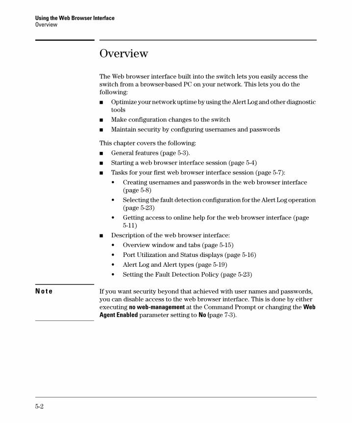
Using the Web Browser Interface Overview
Overview
The Web browser interface built into the switch lets you easily access the switch from a browser-based PC on your network. This lets you do the following:
■ Optimize your network uptime by using the Alert Log and other diagnostic tools
■ Make configuration changes to the switch
■ Maintain security by configuring usernames and passwords
This chapter covers the following:
■ General features (page 5-3).
■ Starting a web browser interface session (page 5-4)
■ Tasks for your first web browser interface session (page 5-7):
• Creating usernames and passwords in the web browser interface (page 5-8)
• Selecting the fault detection configuration for the Alert Log operation (page 5-23)
• Getting access to online help for the web browser interface (page 5-11)
■ Description of the web browser interface:
• Overview window and tabs (page 5-15)
• Port Utilization and Status displays (page 5-16)
• Alert Log and Alert types (page 5-19)
• Setting the Fault Detection Policy (page 5-23)
N o t e If you want security beyond that achieved with user names and passwords, you can disable access to the web browser interface. This is done by either executing no web-management at the Command Prompt or changing the Web Agent Enabled parameter setting to No (page 7-3).
5-2
Using the Web Browser Interface General Features
General Features
The switch includes these web browser interface features:
Switch Configuration:
• Ports
• VLANs and Primary VLAN
• Fault detection
• Port monitoring (mirroring)
• System information
• Enable/Disable Multicast Filtering (IGMP) and Spanning Tree
• IP
• Stacking
• Support and management URLs
Switch Security: Usernames and passwords
Switch Diagnostics:
• Ping/Link Test
• Device reset
• Configuration report
Switch status
• Port utilization
• Port counters
• Port status
• Alert log
Switch system information listing
5-3
Using the Web Browser Interface Starting a Web Browser Interface Session with the Switch
Starting a Web Browser Interface Session with the Switch
You can start a web browser session in the following ways:
■ Using a standalone web browser on a network connection from a PC or UNIX workstation:
• Directly connected to your network
• Connected through remote access to your network
■ Using a management station running ProCurve Manager on your network
Using a Standalone Web Browser in a PC or UNIX Workstation
This procedure assumes that you are using a compatible web browser (see the software Release Notes for more information) and that the switch is configured with an IP address accessible from your PC or workstation. (For more on assigning an IP address, refer to “IP Configuration” on page 8-3.)
1. Ensure that the JavaTM applets are enabled for your browser. For more information on this topic, refer to your browser’s online Help.
2. Use the web browser to access the switch. If your network includes a Domain Name Server (DNS), your switch’s IP address may have a name associated with it (for example, switch5308) that you can type in the Location or Address field instead of the IP address. Using DNS names typically improves browser performance. Contact your network administrator to enquire about DNS names associated with your ProCurve switch.
Type the IP address (or DNS name) of the switch in the browser Location or Address (URL) field and press [Enter]. (It is not necessary to include http://.)
switch5308 [Enter] (example of a DNS-type name)
10.11.12.195 [Enter] (example of an IP address)
5-4
Using the Web Browser Interface Starting a Web Browser Interface Session with the Switch
Using ProCurve Manager (PCM) or ProCurve Manager Plus (PCM+)
ProCurve Manager and ProCurve Manager Plus are designed for installation on a network management workstation. For this reason, the system requirements are different from the system requirements for accessing the switch’s web browser interface from a non-management PC or workstation. For ProCurve PCM and PCM+ requirements, refer to the information provided with the software.
This procedure assumes that:
■ You have installed the recommended web browser on a PC or workstation that serves as your network management station.
■ The networked device you want to access has been assigned an IP address and (optionally) a DNS name, and has been discovered by PCM or PCM+. (For more on assigning an IP address, refer to “IP Configuration” on page 8-3.)
To establish a web browser session with ProCurve PCM or PCM+ running, do the following on the network management station:
1. Make sure the JavaTM applets are enabled for your web browser. If they are not, refer to the web browser online Help for specific information on enabling the Java applets.
2. In the Interconnected Devices listing under Network Manager Home (in the PCM/PCM+ sidebar), right-click on the model number of the device you want to access.
3. The web browser interface automatically starts with the Status Overview window displayed for the selected device, as shown in figure 5-1.
N o t e If the Registration window appears, click on the Status tab.
5-5
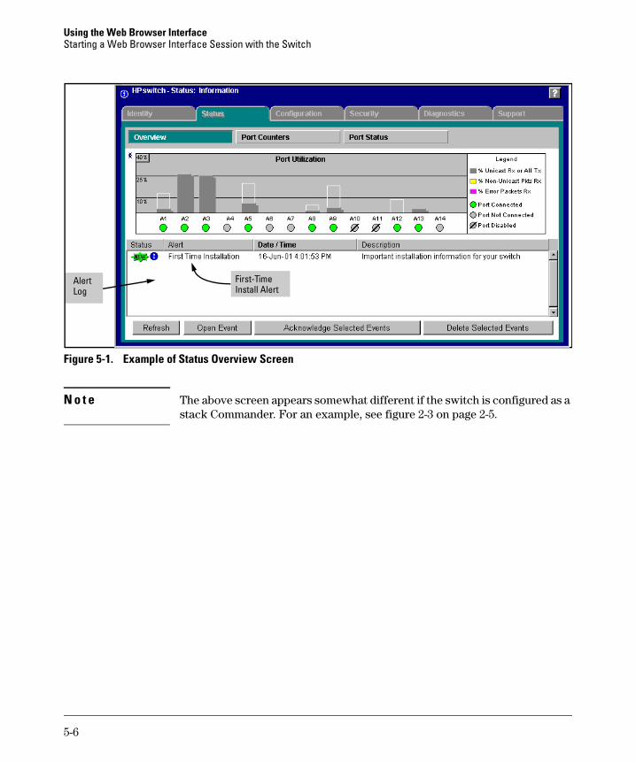
Using the Web Browser Interface Starting a Web Browser Interface Session with the Switch
Log iAlert First-T me
Install Alert
Figure 5-1. Example of Status Overview Screen
N o t e The above screen appears somewhat different if the switch is configured as a stack Commander. For an example, see figure 2-3 on page 2-5.
5-6
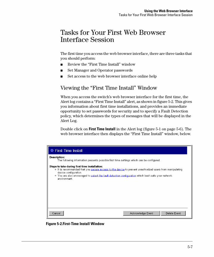
Using the Web Browser Interface Tasks for Your First Web Browser Interface Session
Tasks for Your First Web Browser Interface Session
The first time you access the web browser interface, there are three tasks that you should perform:
■ Review the “First Time Install” window
■ Set Manager and Operator passwords
■ Set access to the web browser interface online help
Viewing the “First Time Install” Window
When you access the switch’s web browser interface for the first time, the Alert log contains a “First Time Install” alert, as shown in figure 5-2. This gives you information about first time installations, and provides an immediate opportunity to set passwords for security and to specify a Fault Detection policy, which determines the types of messages that will be displayed in the Alert Log.
Double click on First Time Install in the Alert log (figure 5-1 on page 5-6). The web browser interface then displays the “First Time Install” window, below.
Figure 5-2.First-Time Install Window
5-7
Using the Web Browser Interface Tasks for Your First Web Browser Interface Session
This window is the launching point for the basic configuration you need to perform to set web browser interface passwords to maintain security and Fault Detection policy, which determines the types of messages that will be displayed in the Alert Log.
To set web browser interface passwords, click on secure access to the device to display the Device Passwords screen, and then go to the next page. (You can also access the password screen by clicking on the Security tab.)
To set Fault Detection policy, click on select the fault detection configuration in the second bullet in the window and go to the section, “Setting Fault Detection Policy” on page 5-23. (You can also access the password screen by clicking on the Configuration tab, and then [Fault Detection] button.)
Creating Usernames and Passwords in the Browser Interface
You may want to create both a username and password to create access security for your switch. There are two levels of access to the interface that can be controlled by setting user names and passwords:
■ Operator. An Operator-level user name and password allows read-only access to most of the web browser interface, but prevents access to the Security window.
■ Manager. A Manager-level user name and password allows full read/ write access to the web browser interface.
5-8
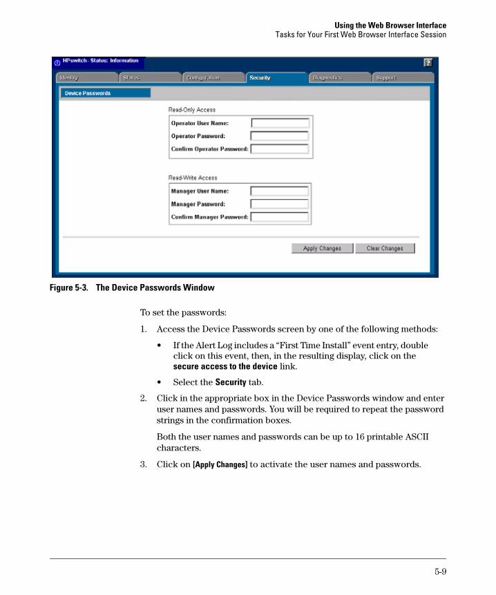
Using the Web Browser Interface Tasks for Your First Web Browser Interface Session
Figure 5-3. The Device Passwords Window
To set the passwords:
1. Access the Device Passwords screen by one of the following methods:
• If the Alert Log includes a “First Time Install” event entry, double click on this event, then, in the resulting display, click on the secure access to the device link.
• Select the Security tab.
2. Click in the appropriate box in the Device Passwords window and enter user names and passwords. You will be required to repeat the password strings in the confirmation boxes.
Both the user names and passwords can be up to 16 printable ASCII characters.
3. Click on [Apply Changes] to activate the user names and passwords.
5-9
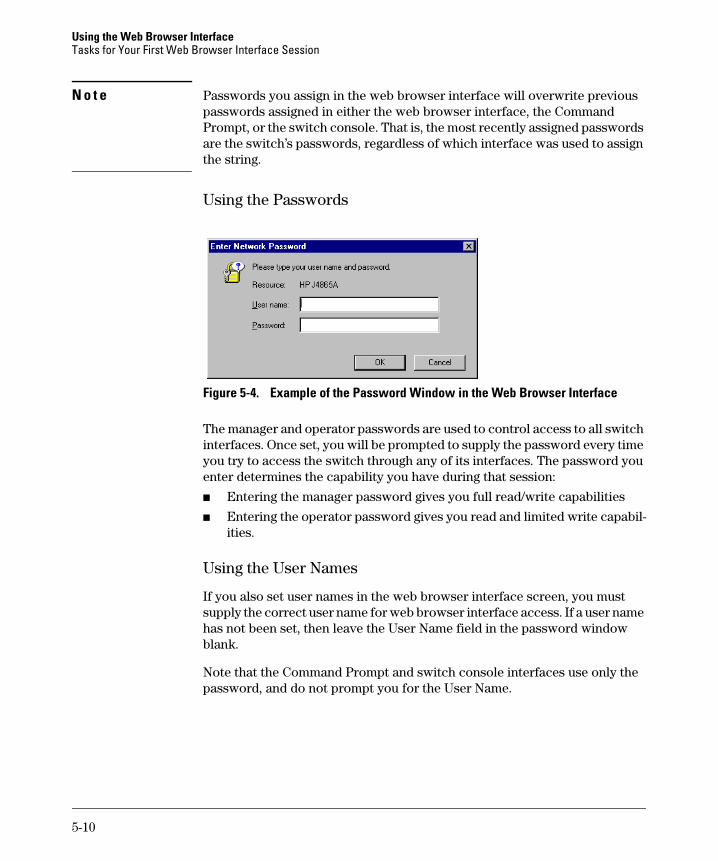
Using the Web Browser Interface Tasks for Your First Web Browser Interface Session
N o t e Passwords you assign in the web browser interface will overwrite previous passwords assigned in either the web browser interface, the Command Prompt, or the switch console. That is, the most recently assigned passwords are the switch’s passwords, regardless of which interface was used to assign the string.
Using the Passwords
Figure 5-4. Example of the Password Window in the Web Browser Interface
The manager and operator passwords are used to control access to all switch interfaces. Once set, you will be prompted to supply the password every time you try to access the switch through any of its interfaces. The password you enter determines the capability you have during that session:
■ Entering the manager password gives you full read/write capabilities
■ Entering the operator password gives you read and limited write capabilities.
Using the User Names
If you also set user names in the web browser interface screen, you must supply the correct user name for web browser interface access. If a user name has not been set, then leave the User Name field in the password window blank.
Note that the Command Prompt and switch console interfaces use only the password, and do not prompt you for the User Name.
5-10
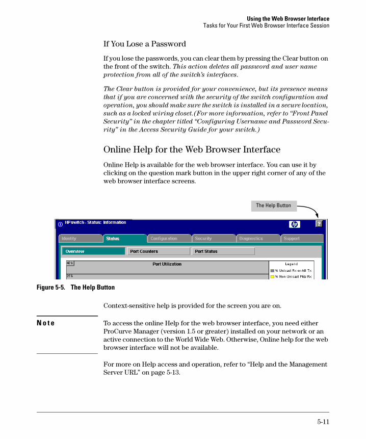
Using the Web Browser Interface Tasks for Your First Web Browser Interface Session
If You Lose a Password
If you lose the passwords, you can clear them by pressing the Clear button on the front of the switch. This action deletes all password and user name
protection from all of the switch’s interfaces.
The Clear button is provided for your convenience, but its presence means
that if you are concerned with the security of the switch configuration and
operation, you should make sure the switch is installed in a secure location,
such as a locked wiring closet.(For more information, refer to “Front Panel
Security” in the chapter titled “Configuring Username and Password Secu
rity” in the Access Security Guide for your switch.)
Online Help for the Web Browser Interface
Online Help is available for the web browser interface. You can use it by clicking on the question mark button in the upper right corner of any of the web browser interface screens.
lThe He p Button
Figure 5-5. The Help Button
Context-sensitive help is provided for the screen you are on.
N o t e To access the online Help for the web browser interface, you need either ProCurve Manager (version 1.5 or greater) installed on your network or an active connection to the World Wide Web. Otherwise, Online help for the web browser interface will not be available.
For more on Help access and operation, refer to “Help and the Management Server URL” on page 5-13.
5-11
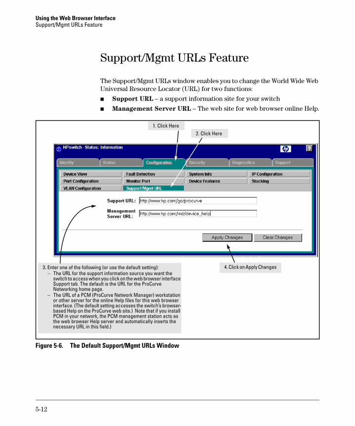
Using the Web Browser Interface Support/Mgmt URLs Feature
Support/Mgmt URLs Feature
The Support/Mgmt URLs window enables you to change the World Wide Web Universal Resource Locator (URL) for two functions:
■ Support URL – a support information site for your switch
■ Management Server URL – The web site for web browser online Help.
– i
–
i i l
lly i
1. Cl
3. Enter one of the following (or use the default setting): The URL for the support information source you want the switch to access when you click on the web browser nterface Support tab. The default is the URL for the ProCurve Networking home page. The URL of a PCM (ProCurve Network Manager) workstation or other server for the online Help files for this web browser nterface. (The default setting accesses the switch’s browser-based Help on the ProCurve web site.) Note that if you nstalPCM in your network, the PCM management station acts as the web browser Help server and automatica nserts the necessary URL in this field.)
ick Here 2. Click Here
4. Click on Apply Changes
Figure 5-6. The Default Support/Mgmt URLs Window
5-12
Using the Web Browser Interface Support/Mgmt URLs Feature
Support URL
This is the site that the switch accesses when you click on the Support tab on the web browser interface. The default URL is:
http://www.procurve.com
which is the web site for ProCurve’s networking products.
Click on the [Support] button on that page and you can get to support information regarding your switch, including white papers, operating system (OS) updates, and more.
You could instead enter the URL for a local site that you use for entering reports about network performance, or whatever other function you would like to be able to easily access by clicking on the [Support] tab.
Help and the Management Server URL
The Management Server URL field specifies the URL the switch uses to find online Help for the web browser interface.
■ If you install PCM (ProCurve Manager) in your network, the PCM management station acts as the web browser Help server for the switch and automatically inserts the necessary URL in this field.)
■ In the default configuration (and if PCM is not running on your network) this field is set to the URL for accessing online Help from the ProCurve Networking Website:
http://www.procurve.com Using this option, the Help files are automatically available if your workstation can access the World Wide Web. In this case, if Online Help fails to operate, ensure that the above URL appears in the Management Server URL field shown in figure 5-7:
5-13
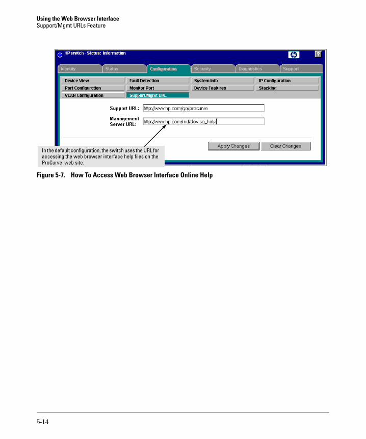
Using the Web Browser Interface Support/Mgmt URLs Feature
i lIn the default configuration, the switch uses the URL for accessing the web browser nterface he p files on the ProCurve web site.
Figure 5-7. How To Access Web Browser Interface Online Help
5-14
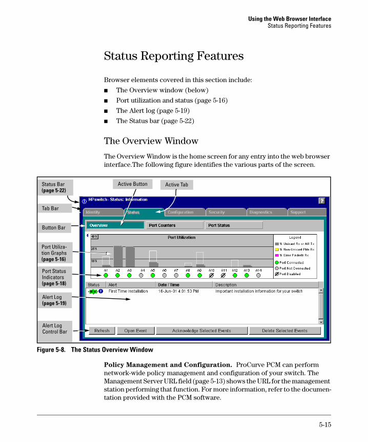
Using the Web Browser Interface Status Reporting Features
Status Reporting Features
Browser elements covered in this section include:
■ The Overview window (below)
■ Port utilization and status (page 5-16)
■ The Alert log (page 5-19)
■ The Status bar (page 5-22)
The Overview Window
The Overview Window is the home screen for any entry into the web browser interface.The following figure identifies the various parts of the screen.
l
Port Status
Alert Log Contro Bar
Port Utilization Graphs (page 5-16)
Active Tab Active Button
Alert Log (page 5-19)
Indicators (page 5-18)
Button Bar
Tab Bar
Status Bar (page 5-22)
Figure 5-8. The Status Overview Window
Policy Management and Configuration. ProCurve PCM can perform network-wide policy management and configuration of your switch. The Management Server URL field (page 5-13) shows the URL for the management station performing that function. For more information, refer to the documentation provided with the PCM software.
5-15
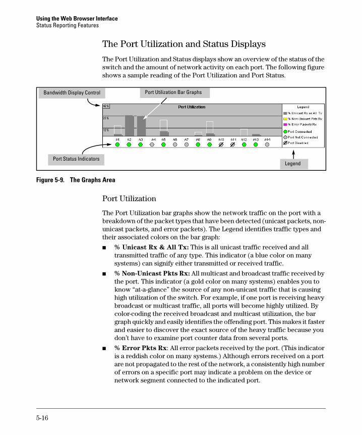
Using the Web Browser Interface Status Reporting Features
The Port Utilization and Status Displays
The Port Utilization and Status displays show an overview of the status of the switch and the amount of network activity on each port. The following figure shows a sample reading of the Port Utilization and Port Status.
Port Utilil
Port Status Indicators
zation Bar Graphs Bandwidth Display Contro
Legend
Figure 5-9. The Graphs Area
Port Utilization
The Port Utilization bar graphs show the network traffic on the port with a breakdown of the packet types that have been detected (unicast packets, nonunicast packets, and error packets). The Legend identifies traffic types and their associated colors on the bar graph:
■ % Unicast Rx & All Tx: This is all unicast traffic received and all transmitted traffic of any type. This indicator (a blue color on many systems) can signify either transmitted or received traffic.
■ % Non-Unicast Pkts Rx: All multicast and broadcast traffic received by the port. This indicator (a gold color on many systems) enables you to know “at-a-glance” the source of any non-unicast traffic that is causing high utilization of the switch. For example, if one port is receiving heavy broadcast or multicast traffic, all ports will become highly utilized. By color-coding the received broadcast and multicast utilization, the bar graph quickly and easily identifies the offending port. This makes it faster and easier to discover the exact source of the heavy traffic because you don’t have to examine port counter data from several ports.
■ % Error Pkts Rx: All error packets received by the port. (This indicator is a reddish color on many systems.) Although errors received on a port are not propagated to the rest of the network, a consistently high number of errors on a specific port may indicate a problem on the device or network segment connected to the indicated port.
5-16

Using the Web Browser Interface Status Reporting Features
■ Maximum Activity Indicator: As the bars in the graph area change height to reflect the level of network activity on the corresponding port, they leave an outline to identify the maximum activity level that has been observed on the port.
Utilization Guideline. A network utilization of 40% is considered the maximum that a typical Ethernet-type network can experience before encountering performance difficulties. If you observe utilization that is consistently higher than 40% on any port, click on the Port Counters button to get a detailed set of counters for the port.
To change the amount of bandwidth the Port Utilization bar graph
shows. Click on the bandwidth display control button in the upper left corner of the graph. (The button shows the current scale setting, such as 40%.) In the resulting menu, select the bandwidth scale you want the graph to show (3%, 10%, 25%, 40%, 75%, or 100%), as shown in figure figure 5-10.
Note that when viewing activity on a gigabit port, you may want to select a lower value (such as 3% or 10%). This is because the bandwidth utilization of current network applications on gigabit links is typically minimal, and may not appear on the graph if the scale is set to show high bandwidth utilization.
Figure 5-10. Changing the Graph Area Scale
To display values for each graph bar. Hold the mouse cursor over any of the bars in the graph, and a pop-up display is activated showing the port identification and numerical values for each of the sections of the bar, as shown in figure 5-11 (next).
Figure 5-11. Display of Numerical Values for the Bar
5-17
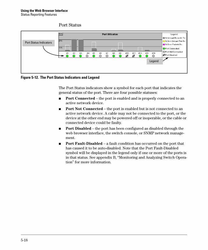
Using the Web Browser Interface Status Reporting Features
Port Status
Port Status Indicators
Legend
Figure 5-12. The Port Status Indicators and Legend
The Port Status indicators show a symbol for each port that indicates the general status of the port. There are four possible statuses:
■ Port Connected – the port is enabled and is properly connected to an active network device.
■ Port Not Connected – the port is enabled but is not connected to an active network device. A cable may not be connected to the port, or the device at the other end may be powered off or inoperable, or the cable or connected device could be faulty.
■ Port Disabled – the port has been configured as disabled through the web browser interface, the switch console, or SNMP network management.
■ Port Fault-Disabled – a fault condition has occurred on the port that has caused it to be auto-disabled. Note that the Port Fault-Disabled symbol will be displayed in the legend only if one or more of the ports is in that status. See appendix B, “Monitoring and Analyzing Switch Operation” for more information.
5-18
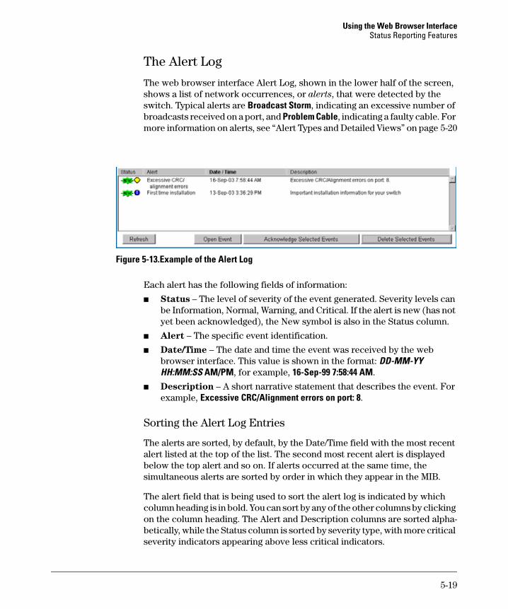
Using the Web Browser Interface Status Reporting Features
The Alert Log
The web browser interface Alert Log, shown in the lower half of the screen, shows a list of network occurrences, or alerts, that were detected by the switch. Typical alerts are Broadcast Storm, indicating an excessive number of broadcasts received on a port, and Problem Cable, indicating a faulty cable. For more information on alerts, see “Alert Types and Detailed Views” on page 5-20
Figure 5-13.Example of the Alert Log
Each alert has the following fields of information:
■ Status – The level of severity of the event generated. Severity levels can be Information, Normal, Warning, and Critical. If the alert is new (has not yet been acknowledged), the New symbol is also in the Status column.
■ Alert – The specific event identification.
■ Date/Time – The date and time the event was received by the web browser interface. This value is shown in the format: DD-MM-YY HH:MM:SS AM/PM, for example, 16-Sep-99 7:58:44 AM.
■ Description – A short narrative statement that describes the event. For example, Excessive CRC/Alignment errors on port: 8.
Sorting the Alert Log Entries
The alerts are sorted, by default, by the Date/Time field with the most recent alert listed at the top of the list. The second most recent alert is displayed below the top alert and so on. If alerts occurred at the same time, the simultaneous alerts are sorted by order in which they appear in the MIB.
The alert field that is being used to sort the alert log is indicated by which column heading is in bold. You can sort by any of the other columns by clicking on the column heading. The Alert and Description columns are sorted alphabetically, while the Status column is sorted by severity type, with more critical severity indicators appearing above less critical indicators.
5-19

Using the Web Browser Interface Status Reporting Features
Alert Types and Detailed Views
As of April, 2004, the web browser interface generates the following alert types:
• Auto Partition • High collision or drop rate • Backup Transition • Loss of Link • Excessive broadcasts • Mis-Configured SQE • Excessive CRC/alignment errors • Network Loop • Excessive jabbering • Polarity Reversal • Excessive late collisions • Security Violation • First Time Install • Stuck 10BaseT Port • Full-Duplex Mismatch • Too many undersized (runt)/giant • Half-Duplex Mismatch packets
• Transceiver Hot Swap
N o t e When troubleshooting the sources of alerts, it may be helpful to check the switch’s Port Status and Port Counter windows and the Event Log in the console interface.
By double clicking on Alert Entries, the web browser interface displays a Detail View or separate window detailing information about the events. The Detail View contains a description of the problem and a possible solution. It also provides four management buttons:
■ Acknowledge Event – removes the New symbol from the log entry
■ Delete Event – removes the alert from the Alert Log
■ Cancel Button – closes the detail view with no change to the status of the alert and returns you to the Overview screen.
A sample Detail View describing an Excessive CRC/Alignment Error alert is shown here.
5-20
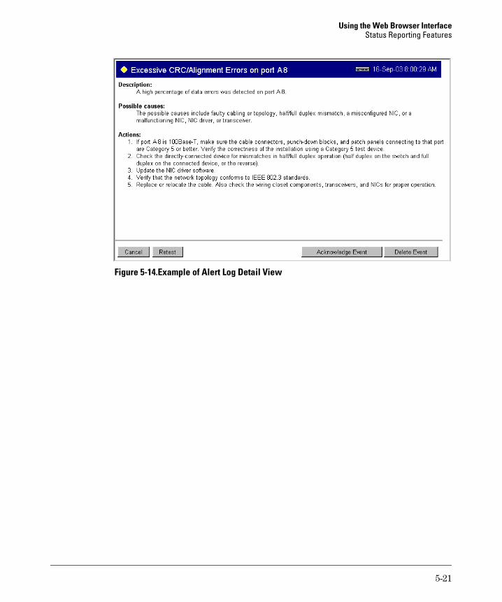
Using the Web Browser Interface Status Reporting Features
Figure 5-14.Example of Alert Log Detail View
5-21
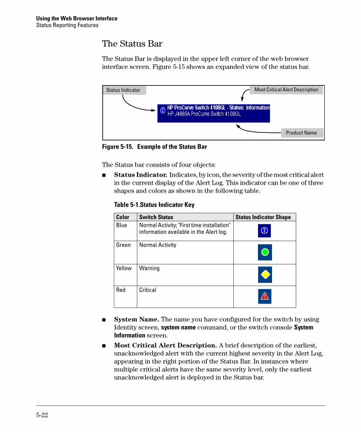
Using the Web Browser Interface Status Reporting Features
The Status Bar
The Status Bar is displayed in the upper left corner of the web browser interface screen. Figure 5-15 shows an expanded view of the status bar.
iStatus Indicator Most Critical Alert Descr ption
Product Name
Figure 5-15. Example of the Status Bar
The Status bar consists of four objects:
■ Status Indicator. Indicates, by icon, the severity of the most critical alert in the current display of the Alert Log. This indicator can be one of three shapes and colors as shown in the following table.
Table 5-1.Status Indicator Key
Color Switch Status Status Indicator Shape Blue Normal Activity; "First time installation"
information available in the Alert log.
Green Normal Activity
Yellow Warning
Red Critical
■ System Name. The name you have configured for the switch by using Identity screen, system name command, or the switch console System Information screen.
■ Most Critical Alert Description. A brief description of the earliest, unacknowledged alert with the current highest severity in the Alert Log, appearing in the right portion of the Status Bar. In instances where multiple critical alerts have the same severity level, only the earliest unacknowledged alert is deployed in the Status bar.
5-22
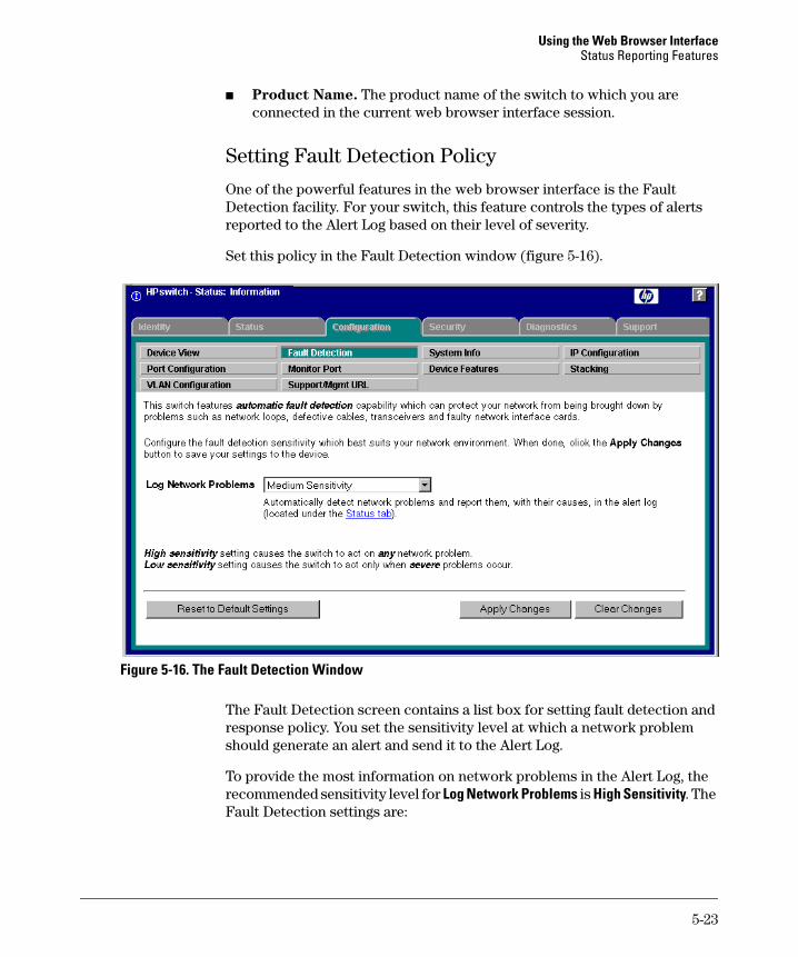
Using the Web Browser Interface Status Reporting Features
■ Product Name. The product name of the switch to which you are connected in the current web browser interface session.
Setting Fault Detection Policy
One of the powerful features in the web browser interface is the Fault Detection facility. For your switch, this feature controls the types of alerts reported to the Alert Log based on their level of severity.
Set this policy in the Fault Detection window (figure 5-16).
Figure 5-16. The Fault Detection Window
The Fault Detection screen contains a list box for setting fault detection and response policy. You set the sensitivity level at which a network problem should generate an alert and send it to the Alert Log.
To provide the most information on network problems in the Alert Log, the recommended sensitivity level for Log Network Problems is High Sensitivity. The Fault Detection settings are:
5-23
Using the Web Browser Interface Status Reporting Features
■ High Sensitivity. This policy directs the switch to send all alerts to the Alert Log. This setting is most effective on networks that have none or few problems.
■ Medium Sensitivity. This policy directs the switch to send alerts related to network problems to the Alert Log. If you want to be notified of problems which cause a noticeable slowdown on the network, use this setting.
■ Low Sensitivity. This policy directs the switch to send only the most severe alerts to the Alert Log. This policy is most effective on a network that normally has a lot of problems and you want to be informed of only the most severe ones.
■ Never. Disables the Alert Log and transmission of alerts (traps) to the management server (in cases where a network management tool such as ProCurve Manager is in use). Use this option when you don’t want to use the Alert Log.
The Fault Detection Window also contains three Change Control Buttons:
■ Apply Changes. This button stores the settings you have selected for all future sessions with the web browser interface until you decide to change them.
■ Clear Changes. This button removes your settings and returns the settings for the list box to the level it was at in the last saved detection-setting session.
■ Reset to Default Settings. This button reverts the policy setting to Medium Sensitivity for Log Network Problems.
5-24
6
Switch Memory and Configuration
Contents
Overview . . . . . . . . . . . . . . . . . . . . . . . . . . . . . . . . . . . . . . . . . . . . . . . . . . . . . . 6-2
Overview of Configuration File Management . . . . . . . . . . . . . . . . . . . . . . . . 6-2
Using the CLI To Implement Configuration Changes . . . . . . . . . . . . . . . . . 6-5
Using the Menu and Web Browser Interfaces To Implement Configuration Changes . . . . . . . . . . . . . . . . . . . . . . . . . . . . . . . . . . . . . . . . . . . . . . . . . . . . . . . 6-8
Configuration Changes Using the Menu Interface . . . . . . . . . . . . . . . . 6-8Using Save and Cancel in the Menu Interface . . . . . . . . . . . . . . . . 6-9Rebooting from the Menu Interface . . . . . . . . . . . . . . . . . . . . . . . 6-10
Configuration Changes Using the Web Browser Interface . . . . . . . . 6-11
Using Primary and Secondary Flash Image Options . . . . . . . . . . . . . . . . . 6-12
Displaying the Current Flash Image Data . . . . . . . . . . . . . . . . . . . . . . 6-12
Switch Software Downloads . . . . . . . . . . . . . . . . . . . . . . . . . . . . . . . . . 6-14
Local Switch Software Replacement and Removal . . . . . . . . . . . . . . 6-15
Rebooting the Switch . . . . . . . . . . . . . . . . . . . . . . . . . . . . . . . . . . . . . . . 6-17
Operating Notes . . . . . . . . . . . . . . . . . . . . . . . . . . . . . . . . . . . . . . . . . . . . 6-19
6-1
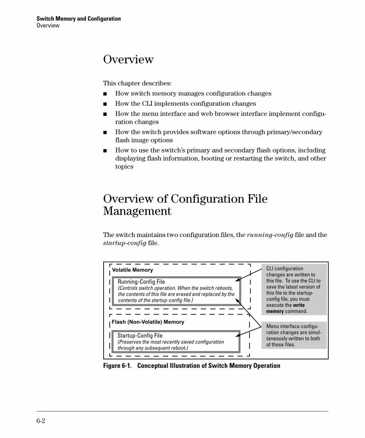
Switch Memory and Configuration Overview
Overview
This chapter describes:
■ How switch memory manages configuration changes
■ How the CLI implements configuration changes
■ How the menu interface and web browser interface implement configuration changes
■ How the switch provides software options through primary/secondary flash image options
■ How to use the switch’s primary and secondary flash options, including displaying flash information, booting or restarting the switch, and other topics
Overview of Configuration File Management
The switch maintains two configuration files, the running-config file and the startup-config file.
Running-Config File
)
this file.
config file, you must write
memory
(Controls switch operation. When the switch reboots, the contents of this file are erased and replaced by the contents of the startup-config file.
Startup-Config File (Preserves the most recently saved configuration through any subsequent reboot.)
Volatile Memory
Flash (Non-Volatile) Memory
CLI configuration changes are written to
To use the CLI to save the latest version of this file to the startup
execute the command.
Menu interface configuration changes are simultaneously written to both of these files.
Figure 6-1. Conceptual Illustration of Switch Memory Operation
6-2
Switch Memory and Configuration Overview of Configuration File Management
■ Running Config File: Exists in volatile memory and controls switch operation. If no configuration changes have been made in the CLI since the switch was last booted, the running-config file is identical to the startup-config file.
■ Startup-config File: Exists in flash (non-volatile) memory and is used to preserve the most recently-saved configuration as the "permanent" configuration.
Rebooting the switch replaces the current running-config file with a new running-config file that is an exact copy of the current startup-config file.
N o t e Any of the following actions reboots the switch:
• Executing the boot or the reload command in the CLI
• Executing the Reboot command in the menu interface
• Pressing the Reset button on the front of the switch
• Removing, then restoring power to the switch
For more on reboots and the switch’s dual-flash images, see “Using Primary and Secondary Flash Image Options” on page 6-12.
Options for Saving a New Configuration. Making one or more changes to the running-config file creates a new operating configuration. Saving a new configuration means to overwrite (replace) the current startup-config file with the current running-config file. This means that if the switch subsequently reboots for any reason, it will resume operation using the new configuration instead of the configuration previously defined in the startup-config file. There are three ways to save a new configuration:
■ In the CLI: Use the write memory command. This overwrites the current startup-config file with the contents of the current running-config file.
■ In the menu interface: Use the Save command. This overwrites both the running-config file and the startup-config file with the changes you have specified in the menu interface screen.
■ In the web browser interface: Use the Apply Changes button or other appropriate button. This overwrites both the running-config file and the startup-config file with the changes you have specified in the web browser interface window.
Note that using the CLI instead of the menu or web browser interface gives you the option of changing the running configuration without affecting the startup configuration. This allows you to test the change without making it
6-3
Switch Memory and Configuration Overview of Configuration File Management
“permanent”. When you are satisfied that the change is satisfactory, you can make it permanent by executing the write memory command. For example, suppose you use the following command to disable port 5:
ProCurve(config)# interface ethernet 5 disable
The above command disables port 5 in the running-config file, but not in the startup-config file. Port 5 remains disabled only until the switch reboots. If you want port 5 to remain disabled through the next reboot, use write memory to save the current running-config file to the startup-config file in flash memory.
ProCurve(config)# write memory
If you use the CLI to make a configuration change and then change from the CLI to the Menu interface without first using write memory to save the change to the startup-config file, then the switch prompts you to save the change. For example, if you use the CLI to create VLAN 20, and then select the menu interface, VLAN 20 is configured in the running-config file, but not in the startup-config file. In this case you will see:
ProCurve(config)# vlan 20ProCurve(config)# menuDo you want to save current configuration [y/n]?
If you type [Y], the switch overwrites the startup-config file with the runningconfig file, and your configuration change(s) will be preserved across reboots. If you type [N], your configuration change(s) will remain only in the runningconfig file. In this case, if you do not subsequently save the running-config file, your unsaved configuration changes will be lost if the switch reboots for any reason.
Storing and Retrieving Configuration Files. You can store or retrieve a backup copy of the startup-config file on another device. For more information, see appendix A, “File Transfers” .
6-4
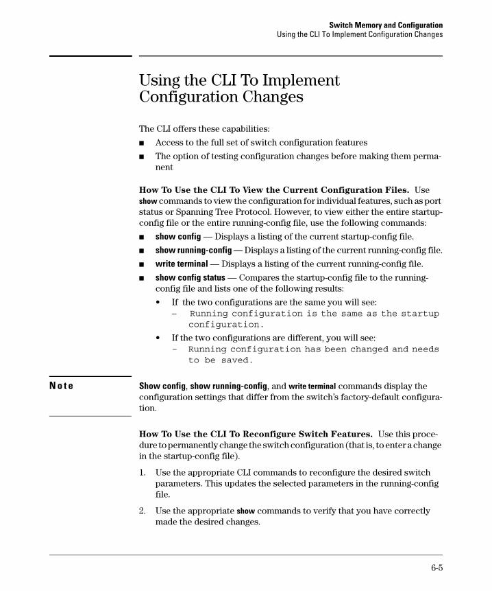
Switch Memory and Configuration Using the CLI To Implement Configuration Changes
Using the CLI To Implement Configuration Changes
The CLI offers these capabilities:
■ Access to the full set of switch configuration features
■ The option of testing configuration changes before making them permanent
How To Use the CLI To View the Current Configuration Files. Use show commands to view the configuration for individual features, such as port status or Spanning Tree Protocol. However, to view either the entire startupconfig file or the entire running-config file, use the following commands:
■ show config — Displays a listing of the current startup-config file.
■ show running-config — Displays a listing of the current running-config file.
■ write terminal — Displays a listing of the current running-config file.
■ show config status — Compares the startup-config file to the runningconfig file and lists one of the following results:
• If the two configurations are the same you will see: – Running configuration is the same as the startup
configuration.
• If the two configurations are different, you will see: – Running configuration has been changed and needs
to be saved.
N o t e Show config, show running-config, and write terminal commands display the configuration settings that differ from the switch’s factory-default configuration.
How To Use the CLI To Reconfigure Switch Features. Use this procedure to permanently change the switch configuration (that is, to enter a change in the startup-config file).
1. Use the appropriate CLI commands to reconfigure the desired switch parameters. This updates the selected parameters in the running-config file.
2. Use the appropriate show commands to verify that you have correctly made the desired changes.
6-5

Switch Memory and Configuration Using the CLI To Implement Configuration Changes
3. Observe the switch’s performance with the new parameter settings to verify the effect of your changes.
4. When you are satisfied that you have the correct parameter settings, use the write memory command to copy the changes to the startup-config file.
Syntax: write memory
For example, the default port mode setting is auto. Suppose that your network uses Cat 3 wiring and you want to connect the switch to another autosensing device capable of 100 Mbps operation. Because 100 Mbps over Cat 3 wiring can introduce transmission problems, the recommended port mode is auto-10, which allows the port to negotiate full- or half-duplex, but restricts speed to 10 Mbps. The following command configures port A5 to auto-10 mode in the running-config file, allowing you to observe performance on the link without making the mode change permanent.
ProCurve(config)# interface e a5 speed-duplex auto-10
After you are satisfied that the link is operating properly, you can save the change to the switch’s permanent configuration (the startup-config file) by executing the following command:
ProCurve(config)# write memory
The new mode (auto-10) on port A5 is now saved in the startup-config file, and the startup-config and running-config files are identical. If you subsequently reboot the switch, the auto-10 mode configuration on port A5 will remain because it is included in the startup-config file.
How To Cancel Changes You Have Made to the Running-Config File.
If you use the CLI to change parameter settings in the running-config file, and then decide that you don’t want those changes to remain, you can use either of the following methods to remove them:
■ Manually enter the earlier values you had for the changed settings. (This is recommended if you want to restore a small number of parameter settings to their previous boot-up values.)
■ Update the running-config file to match the startup-config file by rebooting the switch. (This is recommended if you want to restore a larger number of parameter settings to their previous boot-up values.)
If you use the CLI to change a parameter setting, and then execute the boot command without first executing the write memory command to save the change, the switch prompts you to specify whether to save the changes in the current running-config file. For example:
6-6
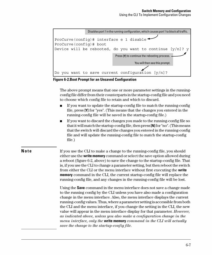
Switch Memory and Configuration Using the CLI To Implement Configuration Changes
Disables port 1 in the running configuration, which causes port 1 to block all traffic.
ProCurve(config)# interface e 1 disableProCurve(config)# bootDevice will be rebooted, do you want to continue [y/n]? y
Press [Y]
ill i
Do you want to save current configuration [y/n]?
to continue the rebooting process.
You w then see th s prompt.
Figure 6-2.Boot Prompt for an Unsaved Configuration
The above prompt means that one or more parameter settings in the runningconfig file differ from their counterparts in the startup-config file and you need to choose which config file to retain and which to discard.
■ If you want to update the startup-config file to match the running-config file, press [Y] for "yes". (This means that the changes you entered in the running-config file will be saved in the startup-config file.)
■ If you want to discard the changes you made to the running-config file so that it will match the startup-config file, then press [N] for "no". (This means that the switch will discard the changes you entered in the running-config file and will update the running-config file to match the startup-config file.)
N o t e If you use the CLI to make a change to the running-config file, you should either use the write memory command or select the save option allowed during a reboot (figure 6-2, above) to save the change to the startup-config file. That is, if you use the CLI to change a parameter setting, but then reboot the switch from either the CLI or the menu interface without first executing the write memory command in the CLI, the current startup-config file will replace the running-config file, and any changes in the running-config file will be lost.
Using the Save command in the menu interface does not save a change made to the running config by the CLI unless you have also made a configuration change in the menu interface. Also, the menu interface displays the current running-config values. Thus, where a parameter setting is accessible from both the CLI and the menu interface, if you change the setting in the CLI, the new value will appear in the menu interface display for that parameter. However,
as indicated above, unless you also make a configuration change in the
menu interface, only the write memory command in the CLI will actually
save the change to the startup-config file.
6-7
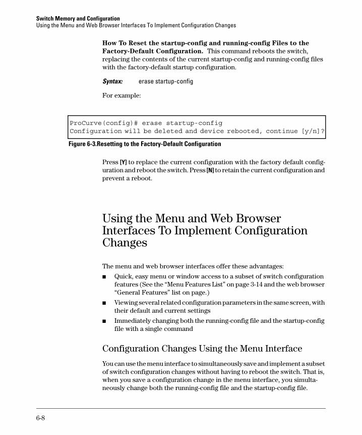
Switch Memory and Configuration Using the Menu and Web Browser Interfaces To Implement Configuration Changes
How To Reset the startup-config and running-config Files to the
Factory-Default Configuration. This command reboots the switch, replacing the contents of the current startup-config and running-config files with the factory-default startup configuration.
Syntax: erase startup-config
For example:
ProCurve(config)# erase startup-configConfiguration will be deleted and device rebooted, continue [y/n]?
Figure 6-3.Resetting to the Factory-Default Configuration
Press [Y] to replace the current configuration with the factory default configuration and reboot the switch. Press [N] to retain the current configuration and prevent a reboot.
Using the Menu and Web Browser Interfaces To Implement Configuration Changes
The menu and web browser interfaces offer these advantages:
■ Quick, easy menu or window access to a subset of switch configuration features (See the “Menu Features List” on page 3-14 and the web browser “General Features” list on page.)
■ Viewing several related configuration parameters in the same screen, with their default and current settings
■ Immediately changing both the running-config file and the startup-config file with a single command
Configuration Changes Using the Menu Interface
You can use the menu interface to simultaneously save and implement a subset of switch configuration changes without having to reboot the switch. That is, when you save a configuration change in the menu interface, you simultaneously change both the running-config file and the startup-config file.
6-8
Switch Memory and Configuration Using the Menu and Web Browser Interfaces To Implement Configuration Changes
N o t e The only exception to this operation are two VLAN-related parameter changes that require a reboot—described under “Rebooting To Activate Configuration Changes” on page 6-11.
Using Save and Cancel in the Menu Interface
For any configuration screen in the menu interface, the Save command:
1. Implements the changes in the running-config file.
2. Saves your changes to the startup-config file.
If you decide not to save and implement the changes in the screen, select Cancel to discard them and continue switch operation with the current operation. For example, suppose you have made the changes shown below in the System Information screen:
l
[S] (for Save). l
[C] (for C )
To save and implement the changes for alparameters in this screen, press the [Enter] key, then press To cancel alchanges, press the [Enter] key, then press ancel
Figure 6-4. Example of Pending Configuration Changes that Can Be Saved or Cancelled
6-9
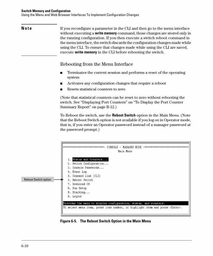
Switch Memory and Configuration Using the Menu and Web Browser Interfaces To Implement Configuration Changes
N o t e If you reconfigure a parameter in the CLI and then go to the menu interface without executing a write memory command, those changes are stored only in the running configuration. If you then execute a switch reboot command in the menu interface, the switch discards the configuration changes made while using the CLI. To ensure that changes made while using the CLI are saved, execute write memory in the CLI before rebooting the switch.
Rebooting from the Menu Interface
■ Terminates the current session and performs a reset of the operating system
■ Activates any configuration changes that require a reboot
■ Resets statistical counters to zero
(Note that statistical counters can be reset to zero without rebooting the switch. See “Displaying Port Counters” on “To Display the Port Counter Summary Report” on page B-12.)
To Reboot the switch, use the Reboot Switch option in the Main Menu. (Note that the Reboot Switch option is not available if you log on in Operator mode, that is, if you enter an Operator password instead of a manager password at the password prompt.)
Reboot Switch option
Figure 6-5. The Reboot Switch Option in the Main Menu
6-10
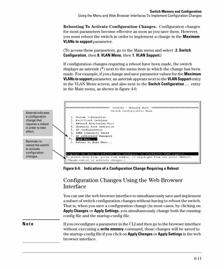
Switch Memory and Configuration Using the Menu and Web Browser Interfaces To Implement Configuration Changes
Rebooting To Activate Configuration Changes. Configuration changes for most parameters become effective as soon as you save them. However, you must reboot the switch in order to implement a change in the Maximum VLANs to support parameter.
(To access these parameters, go to the Main menu and select 2. Switch Configuration, then 8. VLAN Menu, then 1. VLAN Support.)
If configuration changes requiring a reboot have been made, the switch displays an asterisk (*) next to the menu item in which the change has been made. For example, if you change and save parameter values for the Maximum VLANs to support parameter, an asterisk appears next to the VLAN Support entry in the VLAN Menu screen, and also next to the Switch Configuration . . . entry in the Main menu, as shown in figure 4-6:
i
Asteri
effect.
Reminder to reboot the switch to act vate configuration changes.
sk indicates a configuration change that requires a reboot in order to take
Figure 6-6. Indication of a Configuration Change Requiring a Reboot
Configuration Changes Using the Web Browser Interface
You can use the web browser interface to simultaneously save and implement a subset of switch configuration changes without having to reboot the switch. That is, when you save a configuration change (in most cases, by clicking on Apply Changes or Apply Settings, you simultaneously change both the runningconfig file and the startup-config file.
N o t e If you reconfigure a parameter in the CLI and then go to the browser interface without executing a write memory command, those changes will be saved to the startup-config file if you click on Apply Changes or Apply Settings in the web browser interface.
6-11
Switch Memory and Configuration Using Primary and Secondary Flash Image Options
Using Primary and Secondary Flash Image Options
The switch features two flash memory locations for storing switch software image files:
■ Primary Flash: The default storage for a switch software image.
■ Secondary Flash: The additional storage for either a redundant or an alternate switch software image.
With the Primary/Secondary flash option you can test a new image in your system without having to replace a previously existing image. You can also use the image options for troubleshooting. For example, you can copy a problem image into Secondary flash for later analysis and place another, proven image in Primary flash to run your system. The switch can use only one image at a time.
The following tasks involve primary/secondary flash options:
■ Displaying the current flash image data and determining which switch software versions are available
■ Switch software downloads
■ Replacing and removing (erasing) a local switch software version
■ System booting
Displaying the Current Flash Image Data
Use the commands in this section to:
■ Determine whether there are flash images in both primary and secondary flash
■ Determine whether the images in primary and secondary flash are the same
■ Identify which switch software version is currently running
Viewing the Currently Active Flash Image Version. This command identifies the software version on which the switch is currently running, and whether the active version was booted from the primary or secondary flash image.
Syntax: show version
6-12
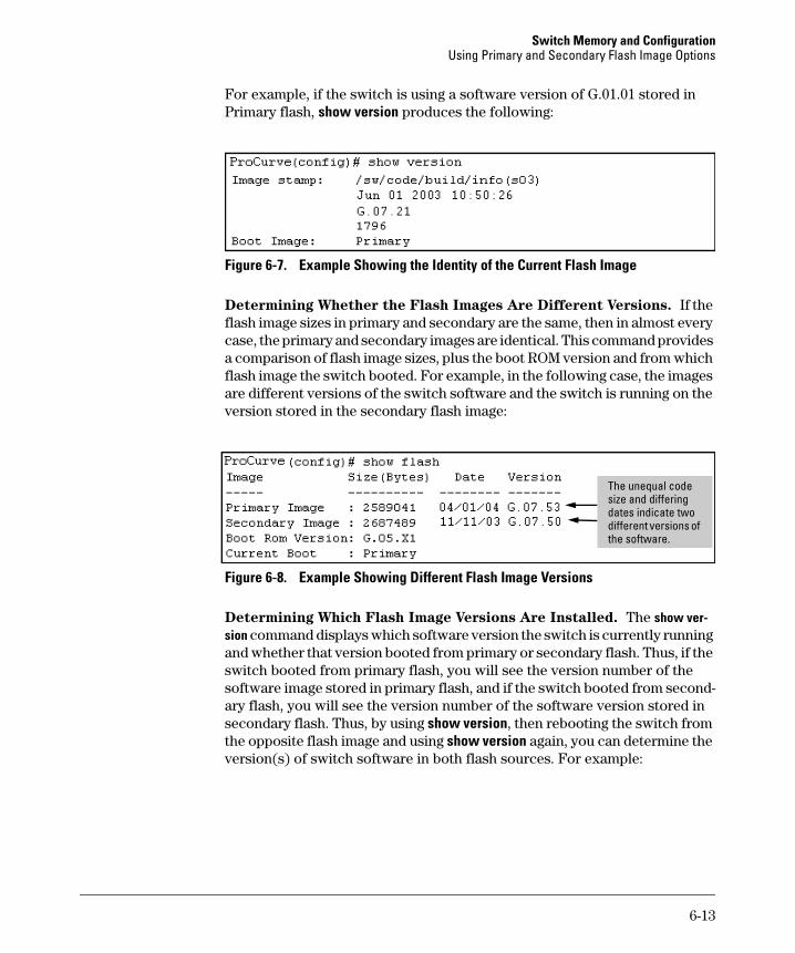
Switch Memory and Configuration Using Primary and Secondary Flash Image Options
For example, if the switch is using a software version of G.01.01 stored in Primary flash, show version produces the following:
Figure 6-7. Example Showing the Identity of the Current Flash Image
Determining Whether the Flash Images Are Different Versions. If the flash image sizes in primary and secondary are the same, then in almost every case, the primary and secondary images are identical. This command provides a comparison of flash image sizes, plus the boot ROM version and from which flash image the switch booted. For example, in the following case, the images are different versions of the switch software and the switch is running on the version stored in the secondary flash image:
i
di
The unequal code size and d ffering dates indicate two
fferent versions of the software.
Figure 6-8. Example Showing Different Flash Image Versions
Determining Which Flash Image Versions Are Installed. The show version command displays which software version the switch is currently running and whether that version booted from primary or secondary flash. Thus, if the switch booted from primary flash, you will see the version number of the software image stored in primary flash, and if the switch booted from secondary flash, you will see the version number of the software version stored in secondary flash. Thus, by using show version, then rebooting the switch from the opposite flash image and using show version again, you can determine the version(s) of switch software in both flash sources. For example:
6-13
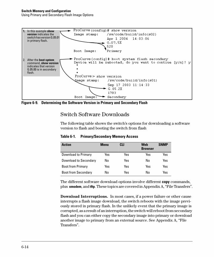
Switch Memory and Configuration Using Primary and Secondary Flash Image Options
1. show indicates the
.
2. command, indi
iflash.
In this example versionswitch has version G.05.01 in primary flash
After the boot system show version
cates that version G.05.00 is n secondary
Figure 6-9. Determining the Software Version in Primary and Secondary Flash
Switch Software Downloads
The following table shows the switch’s options for downloading a software version to flash and booting the switch from flash
Table 6-1. Primary/Secondary Memory Access
Menu CLI Browser
SNMPAction Web
Download to Primary Yes Yes Yes Yes
Download to Secondary No Yes No Yes
Boot from Primary Yes Yes Yes Yes
Boot from Secondary No Yes No Yes
The different software download options involve different copy commands, plus xmodem, and tftp. These topics are covered in Appendix A, “File Transfers”.
Download Interruptions. In most cases, if a power failure or other cause interrupts a flash image download, the switch reboots with the image previously stored in primary flash. In the unlikely event that the primary image is corrupted, as a result of an interruption, the switch will reboot from secondary flash and you can either copy the secondary image into primary or download another image to primary from an external source. See Appendix A, “File Transfers”.
6-14
Switch Memory and Configuration Using Primary and Secondary Flash Image Options
Local Switch Software Replacement and Removal
This section describes commands for erasing a software version and copying an existing software version between primary and secondary flash.
N o t e It is not necessary to erase the content of a flash location before downloading another software file. The process automatically overwrites the previous file with the new file. If you want to remove an unwanted software version from flash, HP recommends that you do so by overwriting it with the same software version that you are using to operate the switch, or with another acceptable software version. To copy a software file between the primary and secondary flash locations, see “Copying a Switch Software Image from One Flash Location to Another” , below.
The local commands described here are for flash image management within the switch. To download a software image file from an external source, see Appendix A, “File Transfers”.
Copying a Switch Software Image from One Flash Location to
Another. When you copy the flash image from primary to secondary or the reverse, the switch overwrites the file in the destination location with a copy of the file from the source location. This means you do not have to erase the current image at the destination location before copying in a new image.
C a u t i o n Verify that there is an acceptable software version in the source flash location from which you are going to copy. Use the show flash command or, if necessary, the procedure under “Determining Which Flash Image Versions Are Installed” on page 6-13 to verify an acceptable software version. Attempting to copy from a source image location that has a corrupted flash image overwrites the image in the destination flash location. In this case, the switch will not have a valid flash image in either flash location, but will continue running on a temporary flash image in RAM. Do not reboot the switch. Instead, immediately download another valid flash image to primary or secondary flash. Otherwise, if the switch is rebooted without a software image in either primary or secondary flash, the temporary flash image in RAM will be cleared and the switch will go down. To recover, see “Restoring a Flash Image” on page C-44 (in the Troubleshooting chapter).
Syntax: copy flash flash <destination flash>
where: destination flash = primary or secondary:
For example, to copy the image in secondary flash to primary flash:
6-15
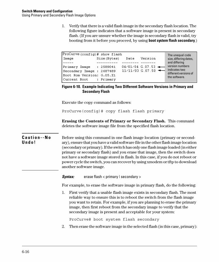
Switch Memory and Configuration Using Primary and Secondary Flash Image Options
1. Verify that there is a valid flash image in the secondary flash location. The following figure indicates that a software image is present in secondary flash. (If you are unsure whether the image is secondary flash is valid, try booting from it before you proceed, by using boot system flash secondary.)
C a u t i o n - - N o U n d o !
sii
i
The unequal code ze, differing dates,
and differ ng version numbers ndicates two
different versions of the software.
Figure 6-10. Example Indicating Two Different Software Versions in Primary and Secondary Flash
Execute the copy command as follows:
ProCurve(config)# copy flash flash primary
Erasing the Contents of Primary or Secondary Flash. This command deletes the software image file from the specified flash location.
Before using this command in one flash image location (primary or secondary), ensure that you have a valid software file in the other flash image location (secondary or primary). If the switch has only one flash image loaded (in either primary or secondary flash) and you erase that image, then the switch does not have a software image stored in flash. In this case, if you do not reboot or power cycle the switch, you can recover by using xmodem or tftp to download another software image.
Syntax: erase flash < primary | secondary >
For example, to erase the software image in primary flash, do the following:
1. First verify that a usable flash image exists in secondary flash. The most reliable way to ensure this is to reboot the switch from the flash image you want to retain. For example, if you are planning to erase the primary image, then first reboot from the secondary image to verify that the secondary image is present and acceptable for your system:
ProCurve# boot system flash secondary
2. Then erase the software image in the selected flash (in this case, primary):
6-16
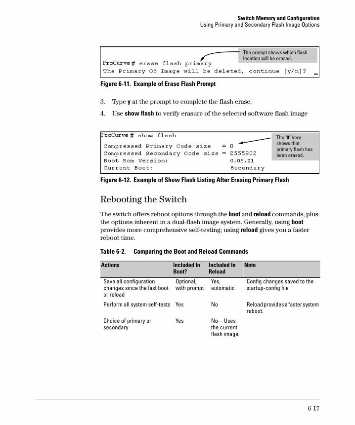
Switch Memory and Configuration Using Primary and Secondary Flash Image Options
l lThe prompt shows which flash ocation wil be erased.
Figure 6-11. Example of Erase Flash Prompt
3. Type y at the prompt to complete the flash erase.
4. Use show flash to verify erasure of the selected software flash image
0The " " here shows that primary flash has been erased.
Figure 6-12. Example of Show Flash Listing After Erasing Primary Flash
Rebooting the Switch
The switch offers reboot options through the boot and reload commands, plus the options inherent in a dual-flash image system. Generally, using boot provides more comprehensive self-testing; using reload gives you a faster reboot time.
Table 6-2. Comparing the Boot and Reload Commands
Actions Included In Boot? Reload
NoteIncluded In
Save all configuration Optional, Yes, Config changes saved to the changes since the last boot with prompt automatic startup-config file or reload
Perform all system self-tests Yes No Reload provides a faster system reboot.
Choice of primary or Yes No—Uses secondary the current
flash image.
6-17
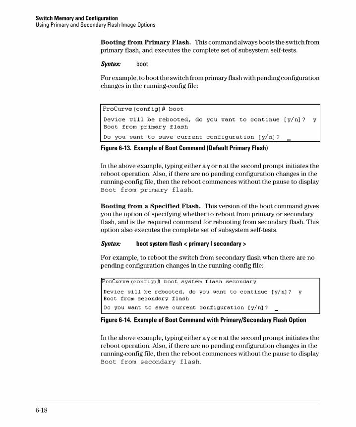
Switch Memory and Configuration Using Primary and Secondary Flash Image Options
Booting from Primary Flash. This command always boots the switch from primary flash, and executes the complete set of subsystem self-tests.
Syntax: boot
For example, to boot the switch from primary flash with pending configuration changes in the running-config file:
Figure 6-13. Example of Boot Command (Default Primary Flash)
In the above example, typing either a y or n at the second prompt initiates the reboot operation. Also, if there are no pending configuration changes in the running-config file, then the reboot commences without the pause to display Boot from primary flash.
Booting from a Specified Flash. This version of the boot command gives you the option of specifying whether to reboot from primary or secondary flash, and is the required command for rebooting from secondary flash. This option also executes the complete set of subsystem self-tests.
Syntax: boot system flash < primary | secondary >
For example, to reboot the switch from secondary flash when there are no pending configuration changes in the running-config file:
Figure 6-14. Example of Boot Command with Primary/Secondary Flash Option
In the above example, typing either a y or n at the second prompt initiates the reboot operation. Also, if there are no pending configuration changes in the running-config file, then the reboot commences without the pause to display Boot from secondary flash.
6-18
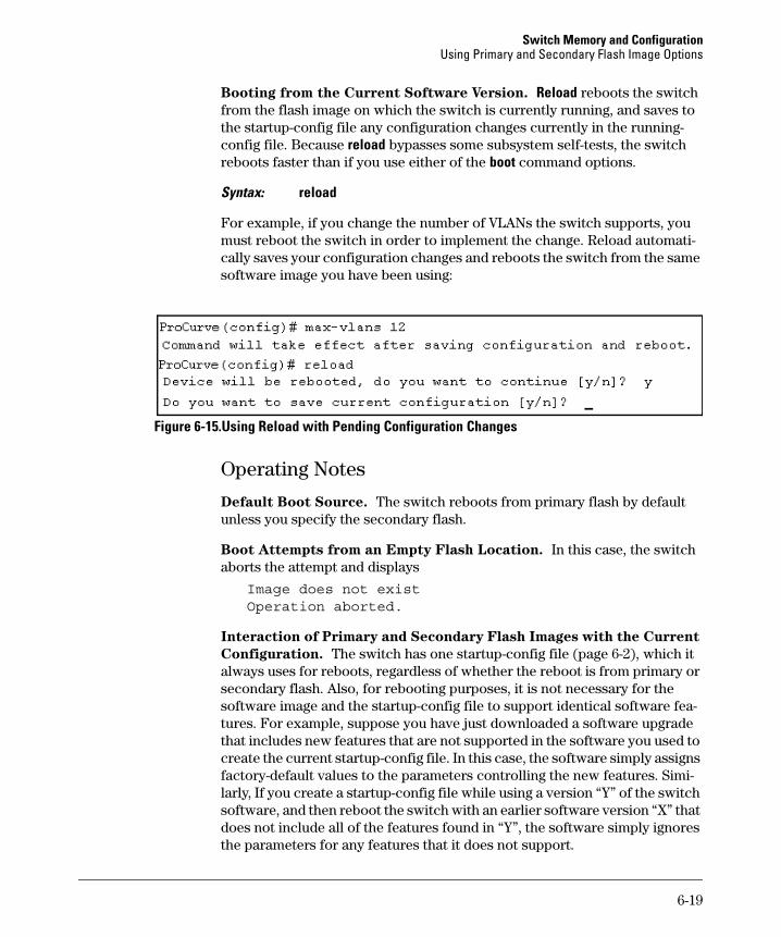
Switch Memory and Configuration Using Primary and Secondary Flash Image Options
Booting from the Current Software Version. Reload reboots the switch from the flash image on which the switch is currently running, and saves to the startup-config file any configuration changes currently in the runningconfig file. Because reload bypasses some subsystem self-tests, the switch reboots faster than if you use either of the boot command options.
Syntax: reload
For example, if you change the number of VLANs the switch supports, you must reboot the switch in order to implement the change. Reload automatically saves your configuration changes and reboots the switch from the same software image you have been using:
Figure 6-15.Using Reload with Pending Configuration Changes
Operating Notes
Default Boot Source. The switch reboots from primary flash by default unless you specify the secondary flash.
Boot Attempts from an Empty Flash Location. In this case, the switch aborts the attempt and displays
Image does not existOperation aborted.
Interaction of Primary and Secondary Flash Images with the Current
Configuration. The switch has one startup-config file (page 6-2), which it always uses for reboots, regardless of whether the reboot is from primary or secondary flash. Also, for rebooting purposes, it is not necessary for the software image and the startup-config file to support identical software features. For example, suppose you have just downloaded a software upgrade that includes new features that are not supported in the software you used to create the current startup-config file. In this case, the software simply assigns factory-default values to the parameters controlling the new features. Similarly, If you create a startup-config file while using a version “Y” of the switch software, and then reboot the switch with an earlier software version “X” that does not include all of the features found in “Y”, the software simply ignores the parameters for any features that it does not support.
6-19

Switch Memory and Configuration Using Primary and Secondary Flash Image Options
— This page is intentionally unused. —
6-20
7
Interface Access and System Information
Contents
Overview . . . . . . . . . . . . . . . . . . . . . . . . . . . . . . . . . . . . . . . . . . . . . . . . . . . . . . 7-2
Interface Access: Console/Serial Link, Web, and Telnet . . . . . . . . . . . . . . . 7-3
Menu: Modifying the Interface Access . . . . . . . . . . . . . . . . . . . . . . . . . . 7-4
CLI: Modifying the Interface Access . . . . . . . . . . . . . . . . . . . . . . . . . . . . 7-5
Denying Access by Terminating Remote Management Sessions . . . . . . . . 7-9
System Information . . . . . . . . . . . . . . . . . . . . . . . . . . . . . . . . . . . . . . . . . . . . 7-10
Menu: Viewing and Configuring System Information . . . . . . . . . . . . . 7-11
CLI: Viewing and Configuring System Information . . . . . . . . . . . . . . 7-12
Web: Configuring System Parameters . . . . . . . . . . . . . . . . . . . . . . . . . 7-15
7-1
Interface Access and System Information Overview
Overview
This chapter describes how to:
■ View and modify the configuration for switch interface access
■ Use the CLI kill command to terminate a remote session
■ View and modify switch system information
For help on how to actually use the interfaces built into the switch, refer to:
■ Chapter 2, “Using the Menu Interface”
■ Chapter 4, “Using the Command Line Interface (CLI)”
■ Chapter 5, “Using the Web Browser Interface”
Why Configure Interface Access and System Information? The interface access features in the switch operate properly by default. However, you can modify or disable access features to suit your particular needs. Similarly, you can choose to leave the system information parameters at their default settings. However, modifying these parameters can help you to more easily distinguish one device from another in your network.
7-2
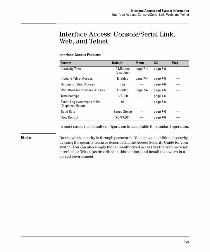
Interface Access and System Information Interface Access: Console/Serial Link, Web, and Telnet
Interface Access: Console/Serial Link, Web, and Telnet
Interface Access Features
Feature Default Menu CLI Web
Inactivity Time
Inbound Telnet Access
Outbound Telnet Access
Web Browser Interface Access
Terminal type
Event Log event types to list(Displayed Events)
Baud Rate
Flow Control
0 Minutes page 7-4 page 7-6 — (disabled)
Enabled page 7-4 page 7-5 —
n/a — page 7-6 —
Enabled page 7-4 page 7-6 —
VT-100 — page 7-6 —
All — page 7-6 —
Speed Sense — page 7-6 —
XON/XOFF — page 7-6 —
In most cases, the default configuration is acceptable for standard operation.
N o t e Basic switch security is through passwords. You can gain additional security by using the security features described in the Access Security Guide for your switch. You can also simply block unauthorized access via the web browser interface or Telnet (as described in this section) and install the switch in a locked environment.
7-3
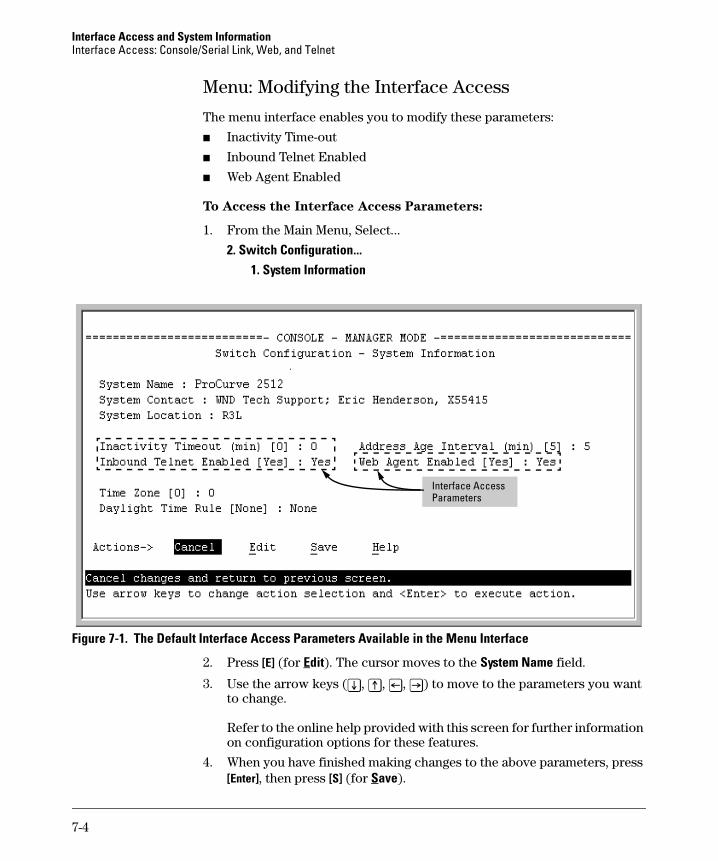
Interface Access and System Information Interface Access: Console/Serial Link, Web, and Telnet
Menu: Modifying the Interface Access
The menu interface enables you to modify these parameters:
■ Inactivity Time-out
■ Inbound Telnet Enabled
■ Web Agent Enabled
To Access the Interface Access Parameters:
1. From the Main Menu, Select...
2. Switch Configuration... 1. System Information
Parameters Interface Access
Figure 7-1. The Default Interface Access Parameters Available in the Menu Interface
2. Press [E] (for Edit). The cursor moves to the System Name field.
3. Use the arrow keys ([v], [^], [<], [>]) to move to the parameters you want to change.
Refer to the online help provided with this screen for further information on configuration options for these features.
4. When you have finished making changes to the above parameters, press [Enter], then press [S] (for Save).
7-4
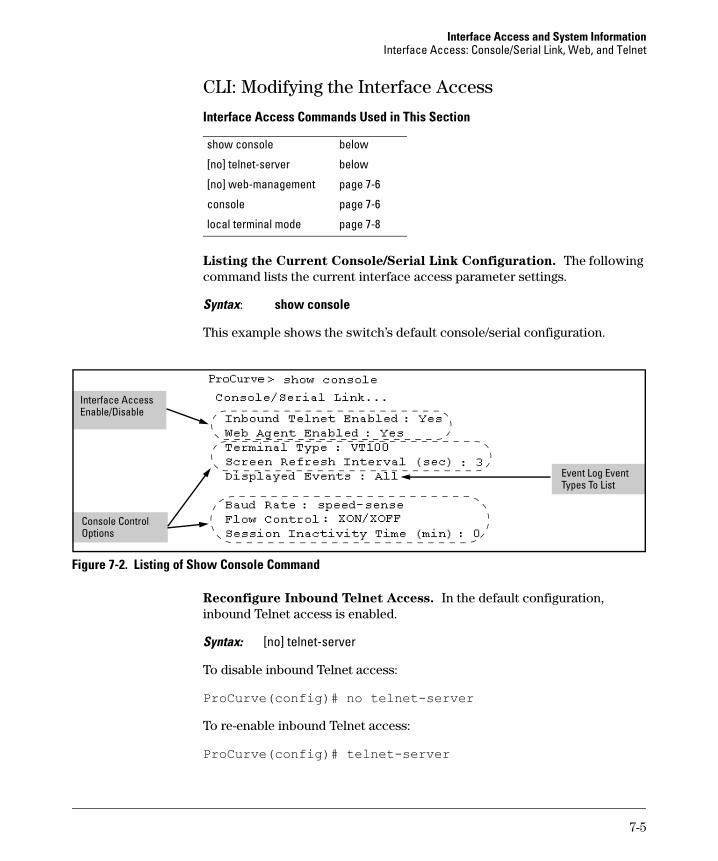
Interface Access and System Information Interface Access: Console/Serial Link, Web, and Telnet
CLI: Modifying the Interface Access
Interface Access Commands Used in This Section
show console below
[no] telnet-server below
[no] web-management page 7-6
console page 7-6
local terminal mode page 7-8
Listing the Current Console/Serial Link Configuration. The following command lists the current interface access parameter settings.
Syntax: show console
This example shows the switch’s default console/serial configuration.
isable
l
Interface Access Enable/D
Console ControOptions
Event Log Event Types To List
Figure 7-2. Listing of Show Console Command
Reconfigure Inbound Telnet Access. In the default configuration, inbound Telnet access is enabled.
Syntax: [no] telnet-server
To disable inbound Telnet access:
ProCurve(config)# no telnet-server
To re-enable inbound Telnet access:
ProCurve(config)# telnet-server
7-5
Interface Access and System Information Interface Access: Console/Serial Link, Web, and Telnet
Outbound Telnet to Another Device. This feature operates independently of the telnet-server status and enables you to Telnet to another device that has an IP address.
Syntax: telnet < ip-address >
For example:
ProCurve# telnet 10.28.27.204
Reconfigure Web Browser Access. In the default configuration, web browser access is enabled.
Syntax: [no] web-management
To disable web browser access:
ProCurve(config)# no web-management
To re-enable web browser access:
ProCurve(config)# web-management
Reconfigure the Console/Serial Link Settings. You can reconfigure one or more console parameters with one console command.
Syntax: console [terminal <vt100 | ansi>] [screen-refresh <1 | 3 | 5 | 10 | 20 | 30 | 45 | 60>] [baud-rate
<speed-sense | 1200 | 2400 | 4800 | 9600 | 19200 |38400 | 57600>] [flow-control <xon/xoff | none>] [inactivity-timer <0 1 5 10 15 20 30 60 120>] [events <none | all | non-info | critical | debug]
N o t e If you change the Baud Rate or Flow Control settings for the switch, you should make the corresponding changes in your console access device. Otherwise, you may lose connectivity between the switch and your terminal emulator due to differences between the terminal and switch settings for these two parameters.
Changes to console parameters require that you perform a write memory and then execute boot before the new console configuration will take effect. To enable temporary and non-disruptive changes to the terminal mode without requiring a reboot, use the console local terminal command (see page 7-8).
7-6
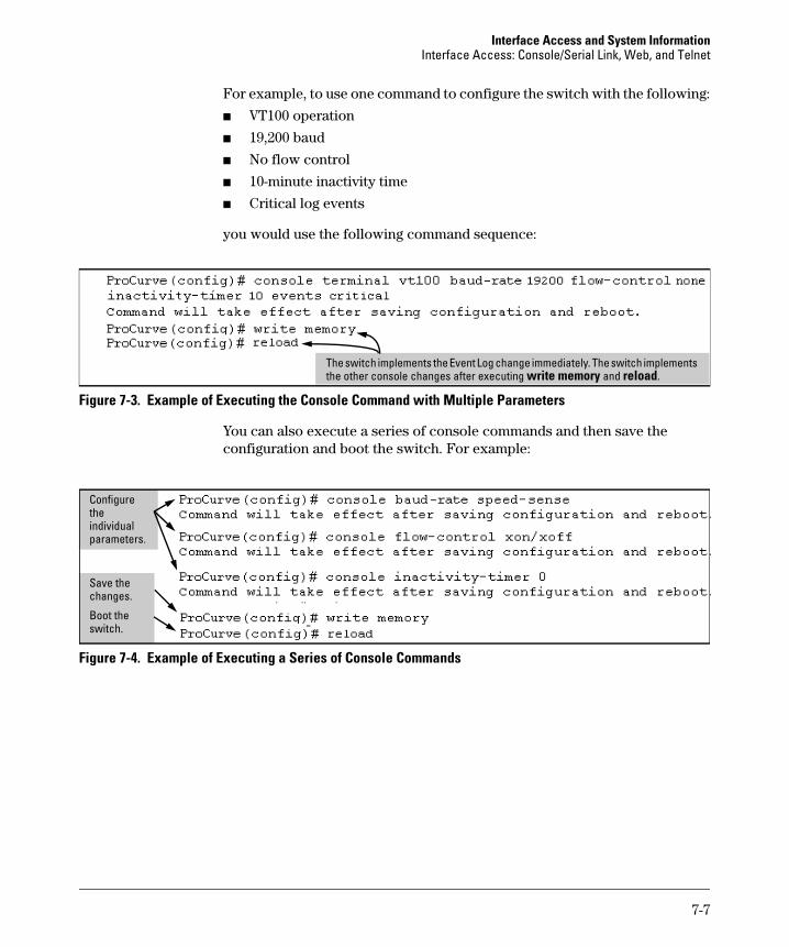
Interface Access and System Information Interface Access: Console/Serial Link, Web, and Telnet
For example, to use one command to configure the switch with the following:
■ VT100 operation
■ 19,200 baud
■ No flow control
■ 10-minute inactivity time
■ Critical log events
you would use the following command sequence:
The switch implements the Event Log change immediately. The switch implements the other console changes after executing write memory and reload.
Figure 7-3. Example of Executing the Console Command with Multiple Parameters
You can also execute a series of console commands and then save the configuration and boot the switch. For example:
the l
Save the
switch.
Configure
individuaparameters.
changes.
Boot the
Figure 7-4. Example of Executing a Series of Console Commands
7-7
Interface Access and System Information Interface Access: Console/Serial Link, Web, and Telnet
CLI Local Terminal Mode (Series 2800 switches). To enable temporary and non-disruptive changes to the terminal mode without forcing a change in the switch’s terminal mode configuration, use the console local-terminal command. This command dynamically changes only the console session from which it is executed. Unlike the console terminal command, it does not require write memory and a reboot, and does not persist across a reboot.
Syntax: console local-terminal < vt100 | none | ansi >
Dynamically converts the terminal mode of a console session to the
selected mode. Executing console local-terminal affects only the console
session from which it is executed. Rebooting the switch returns the
terminal mode for the affected console session to the configured
terminal mode. This command does not change the configured console
terminal mode configuration. (To change the configured terminal
mode, use the console terminal < vt100 | none | ansi > command, which
requires execution of write memory, followed by a switch reboot, to take
effect.)
vt100
When invoked in a console session, changes the terminal mode to VT-100 for that console session. Use this option when the configured terminal mode is either none (scripting mode) or ansi, and you want to temporarily use the VT-100 mode. (VT-100 is the default terminal mode configuration setting.)
none
When invoked in a console session, changes the terminal mode to “raw” (scripting mode) for that console session. (Scripting mode eliminates unwanted control characters that may appear in some scripting languages.) Use this option when the configured terminal mode is either vt100 or ansi, and you want to temporarily use the scripting mode.
ansi
When invoked in a console session, changes the terminal mode to ANSI for that console session. Use this option when the configured terminal mode is either vt100 (scripting mode) or none, and you want to temporarily use the ANSI mode.
7-8
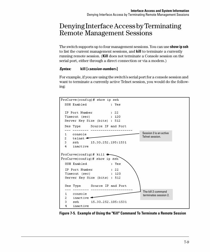
Interface Access and System Information Denying Interface Access by Terminating Remote Management Sessions
Denying Interface Access by Terminating Remote Management Sessions
The switch supports up to four management sessions. You can use show ip ssh to list the current management sessions, and kill to terminate a currently running remote session. (Kill does not terminate a Console session on the serial port, either through a direct connection or via a modem.)
Syntax: kill [<session-number>]
For example, if you are using the switch’s serial port for a console session and want to terminate a currently active Telnet session, you would do the following:
l
Session 2 is an active Telnet session.
The kil 2 command terminates session 2.
Figure 7-5. Example of Using the "Kill" Command To Terminate a Remote Session
7-9
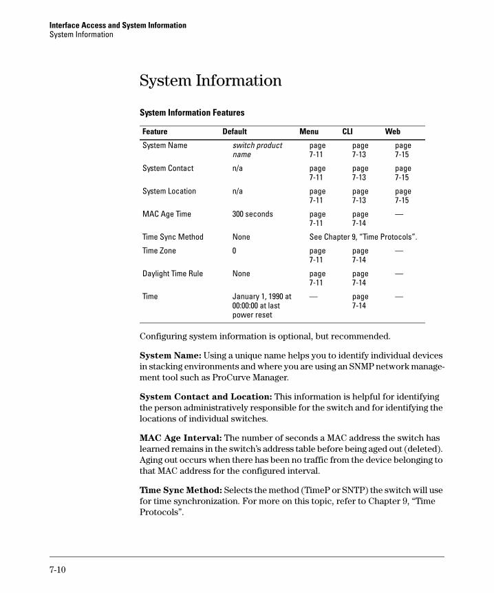
Interface Access and System Information System Information
System Information
System Information Features
Feature Default Menu CLI Web
System Name switch product page page page name 7-11 7-13 7-15
System Contact n/a page page page 7-11 7-13 7-15
System Location n/a page page page 7-11 7-13 7-15
MAC Age Time 300 seconds page page — 7-11 7-14
Time Sync Method None See Chapter 9, “Time Protocols”.
Time Zone 0 page page — 7-11 7-14
Daylight Time Rule None page page — 7-11 7-14
Time January 1, 1990 at — page — 00:00:00 at last 7-14 power reset
Configuring system information is optional, but recommended.
System Name: Using a unique name helps you to identify individual devices in stacking environments and where you are using an SNMP network management tool such as ProCurve Manager.
System Contact and Location: This information is helpful for identifying the person administratively responsible for the switch and for identifying the locations of individual switches.
MAC Age Interval: The number of seconds a MAC address the switch has learned remains in the switch’s address table before being aged out (deleted). Aging out occurs when there has been no traffic from the device belonging to that MAC address for the configured interval.
Time Sync Method: Selects the method (TimeP or SNTP) the switch will use for time synchronization. For more on this topic, refer to Chapter 9, “Time Protocols”.
7-10
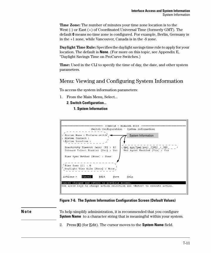
Interface Access and System Information System Information
Time Zone: The number of minutes your time zone location is to the West (-) or East (+) of Coordinated Universal Time (formerly GMT). The default 0 means no time zone is configured. For example, Berlin, Germany is in the +1 zone, while Vancouver, Canada is in the -8 zone.
Daylight Time Rule: Specifies the daylight savings time rule to apply for your location. The default is None. (For more on this topic, see Appendix E, “Daylight Savings Time on ProCurve Switches.)
Time: Used in the CLI to specify the time of day, the date, and other system parameters.
Menu: Viewing and Configuring System Information
To access the system information parameters:
1. From the Main Menu, Select...
2. Switch Configuration... 1. System Information
System Information
Figure 7-6. The System Information Configuration Screen (Default Values)
N o t e To help simplify administration, it is recommended that you configure System Name to a character string that is meaningful within your system.
2. Press [E] (for Edit). The cursor moves to the System Name field.
7-11
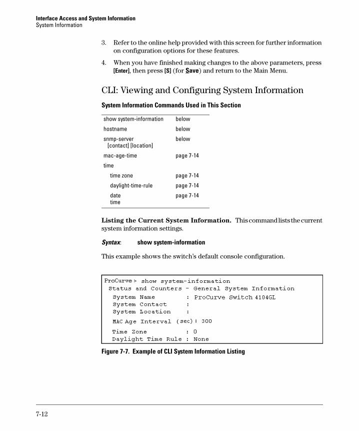
Interface Access and System Information System Information
3. Refer to the online help provided with this screen for further information on configuration options for these features.
4. When you have finished making changes to the above parameters, press [Enter], then press [S] (for Save) and return to the Main Menu.
CLI: Viewing and Configuring System Information
System Information Commands Used in This Section
show system-information below
hostname below
snmp-server below [contact] [location]
mac-age-time page 7-14
time
time zone page 7-14
daylight-time-rule page 7-14
date page 7-14 time
Listing the Current System Information. This command lists the current system information settings.
Syntax: show system-information
This example shows the switch’s default console configuration.
Figure 7-7. Example of CLI System Information Listing
7-12
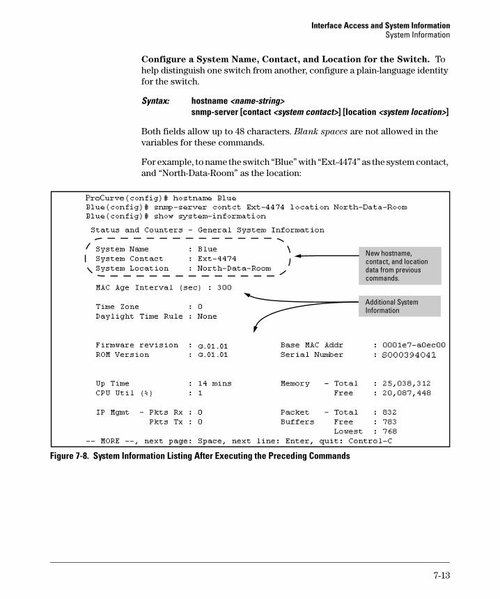
Interface Access and System Information System Information
Configure a System Name, Contact, and Location for the Switch. To help distinguish one switch from another, configure a plain-language identity for the switch.
Syntax: hostname <name-string> snmp-server [contact <system contact>] [location <system location>]
Both fields allow up to 48 characters. Blank spaces are not allowed in the variables for these commands.
For example, to name the switch “Blue” with “Ext-4474” as the system contact, and “North-Data-Room” as the location:
commands.
Information
New hostname, contact, and location data from previous
Additional System
Figure 7-8. System Information Listing After Executing the Preceding Commands
7-13

Interface Access and System Information System Information
Reconfigure the Age Time for Learned MAC Addresses. This command corresponds to the MAC Age Interval in the menu interface, and is expressed in seconds.
Syntax: mac-age-time <10 . . 1000000> (seconds)
For example, to configure the age time to seven minutes:
ProCurve(config)# mac-age-time 420
Configure the Time Zone and Daylight Time Rule. These commands:
■ Set the time zone you want to use
■ Define the daylight time rule for keeping the correct time when daylight-saving-time shifts occur.
Syntax: time timezone <-720 . . 840> time daylight-time-rule <none | alaska | continental-us-and-canada | middle-europe-and-portugal | southern-hemisphere | western-europe | user-defined>
East of the 0 meridian, the sign is “+”. West of the 0 meridian, the sign is “-”.
For example, the time zone setting for Berlin, Germany is +60 (zone +1, or 60 minutes), and the time zone setting for Vancouver, Canada is -480 (zone -8, or -480 minutes). To configure the time zone and daylight time rule for Vancouver, Canada:
ProCurve(config)# time timezone -480 daylight-time-rule continental-us-and-canada
Configure the Time and Date. The switch uses the time command to configure both the time of day and the date. Also, executing time without parameters lists the switch’s time of day and date. Note that the CLI uses a 24-hour clock scheme; that is, hour (hh) values from 1 p.m. to midnight are input as 13 - 24, respectively.
Syntax: time [hh:mm[:ss]] [mm/dd/ [yy]yy]
For example, to set the switch to 9:45 a.m. on November 17, 2002:
ProCurve(config)# time 9:45 11/17/02
N o t e Executing reload or boot resets the time and date to their default startup values.
7-14
Interface Access and System Information System Information
Web: Configuring System Parameters
In the web browser interface, you can enter the following system information:
■ System Name
■ System Location
■ System Contact
For access to the MAC Age Interval and the Time parameters, use the menu interface or the CLI.
Configure System Parameters in the Web Browser Interface.
1. Click on the Configuration tab.
2. Click on System Info.
3. Enter the data you want in the displayed fields.
4. Implement your new data by clicking on Apply Changes.
To access the web-based help provided for the switch, click on [?] in the web browser screen.
7-15

Interface Access and System Information System Information
— This page is intentionally unused. —
7-16
8
Configuring IP Addressing
Contents
Overview . . . . . . . . . . . . . . . . . . . . . . . . . . . . . . . . . . . . . . . . . . . . . . . . . . . . . . 8-2
IP Configuration . . . . . . . . . . . . . . . . . . . . . . . . . . . . . . . . . . . . . . . . . . . . . . . . 8-3
Just Want a Quick Start with IP Addressing? . . . . . . . . . . . . . . . . . . . . 8-4
IP Addressing with Multiple VLANs . . . . . . . . . . . . . . . . . . . . . . . . . . . . 8-4
IP Addressing in a Stacking Environment . . . . . . . . . . . . . . . . . . . . . . . 8-5
Menu: Configuring IP Address, Gateway, and Time-To-Live (TTL) . . 8-5
CLI: Configuring IP Address, Gateway, and Time-To-Live (TTL) . . . . 8-7
Web: Configuring IP Addressing . . . . . . . . . . . . . . . . . . . . . . . . . . . . . . 8-11
How IP Addressing Affects Switch Operation . . . . . . . . . . . . . . . . . . . 8-11DHCP/Bootp Operation . . . . . . . . . . . . . . . . . . . . . . . . . . . . . . . . . . 8-12Network Preparations for Configuring DHCP/Bootp . . . . . . . . . 8-15
IP Preserve: Retaining VLAN-1 IP Addressing Across Configuration File Downloads . . . . . . . . . . . . . . . . . . . . . . . . . . . . . . . . . . . . . . . . . . . . . . . . 8-16
8-1
Configuring IP Addressing Overview
Overview
You can configure IP addressing through all of the switch’s interfaces. You can also:
■ Easily edit a switch configuration file to allow downloading the file to multiple switches without overwriting each switch’s unique gateway and VLAN 1 IP addressing.
■ Assign up to seven secondary IP addresses to a VLAN (multinetting)
Why Configure IP Addressing? In its factory default configuration, the switch operates as a multiport learning bridge with network connectivity provided by the ports on the switch. However, to enable specific management access and control through your network, you will need IP addressing. Table 8-1 on page 8-12 shows the switch features that depend on IP addressing to operate.
8-2
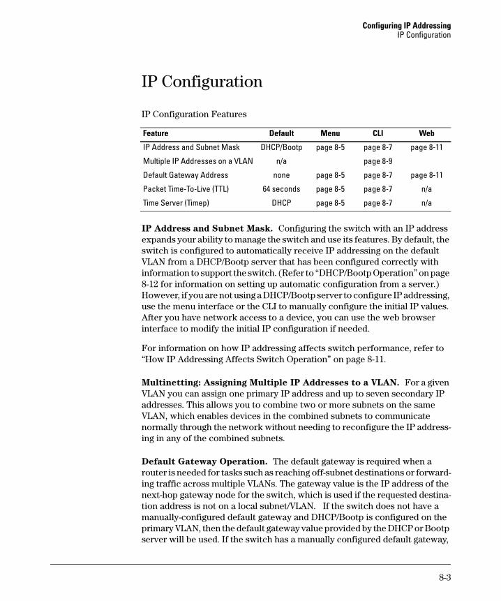
Configuring IP Addressing IP Configuration
IP Configuration
IP Configuration Features
Feature Default Menu CLI Web
IP Address and Subnet Mask DHCP/Bootp page 8-5 page 8-7 page 8-11
Multiple IP Addresses on a VLAN n/a page 8-9
Default Gateway Address none page 8-5 page 8-7 page 8-11
Packet Time-To-Live (TTL) 64 seconds page 8-5 page 8-7 n/a
Time Server (Timep) DHCP page 8-5 page 8-7 n/a
IP Address and Subnet Mask. Configuring the switch with an IP address expands your ability to manage the switch and use its features. By default, the switch is configured to automatically receive IP addressing on the default VLAN from a DHCP/Bootp server that has been configured correctly with information to support the switch. (Refer to “DHCP/Bootp Operation” on page 8-12 for information on setting up automatic configuration from a server.) However, if you are not using a DHCP/Bootp server to configure IP addressing, use the menu interface or the CLI to manually configure the initial IP values. After you have network access to a device, you can use the web browser interface to modify the initial IP configuration if needed.
For information on how IP addressing affects switch performance, refer to “How IP Addressing Affects Switch Operation” on page 8-11.
Multinetting: Assigning Multiple IP Addresses to a VLAN. For a given VLAN you can assign one primary IP address and up to seven secondary IP addresses. This allows you to combine two or more subnets on the same VLAN, which enables devices in the combined subnets to communicate normally through the network without needing to reconfigure the IP addressing in any of the combined subnets.
Default Gateway Operation. The default gateway is required when a router is needed for tasks such as reaching off-subnet destinations or forwarding traffic across multiple VLANs. The gateway value is the IP address of the next-hop gateway node for the switch, which is used if the requested destination address is not on a local subnet/VLAN. If the switch does not have a manually-configured default gateway and DHCP/Bootp is configured on the primary VLAN, then the default gateway value provided by the DHCP or Bootp server will be used. If the switch has a manually configured default gateway,
8-3
Configuring IP Addressing IP Configuration
N o t e s
then the switch uses this gateway, even if a different gateway is received via DHCP or Bootp on the primary VLAN. (This is also true for TimeP and a non-default Time-To-Live.) See “Notes” on page 8-4 and refer to the chapter on Virtual LANs in the Advanced Traffic Management Guide.
Packet Time-To-Live (TTL) . This parameter specifies how long in seconds an outgoing packet should exist in the network. In most cases, the default setting (64 seconds) is adequate.
Just Want a Quick Start with IP Addressing?
If you just want to give the switch an IP address so that it can communicate on your network, or if you are not using VLANs, HP recommends that you use the Switch Setup screen to quickly configure IP addressing. To do so, do one of the following:
■ Enter setup at the CLI Manager level prompt.
ProCurve# setup
■ Select 8. Run Setup in the Main Menu of the menu interface.
For more on using the Switch Setup screen, see the Installation and Getting
Started Guide you received with the switch.
IP Addressing with Multiple VLANs
In the factory-default configuration, the switch has one, permanent default VLAN (named DEFAULT_VLAN) that includes all ports on the switch. Thus, when only the default VLAN exists in the switch, if you assign an IP address and subnet mask to the switch, you are actually assigning the IP addressing to the DEFAULT_VLAN.
■ If multiple VLANs are configured, then each VLAN can have its own IP address. This is because each VLAN operates as a separate broadcast domain and requires a unique IP address and subnet mask. A default gateway (IP) address for the switch is optional, but recommended.
■ In the factory-default configuration, the default VLAN (named DEFAULT_VLAN) is the switch’s primary VLAN. The switch uses the primary VLAN for learning the default gateway address, (packet) Time-To-Live (TTL), and Timep via DHCP or Bootp. (Other VLANs can also use DHCP or BootP to acquire IP addressing. However, the switch’s gateway, TTL, and TimeP values will be acquired through the primary VLAN only.) For more on VLANs, see the Advanced Traffic Management Guide.
8-4
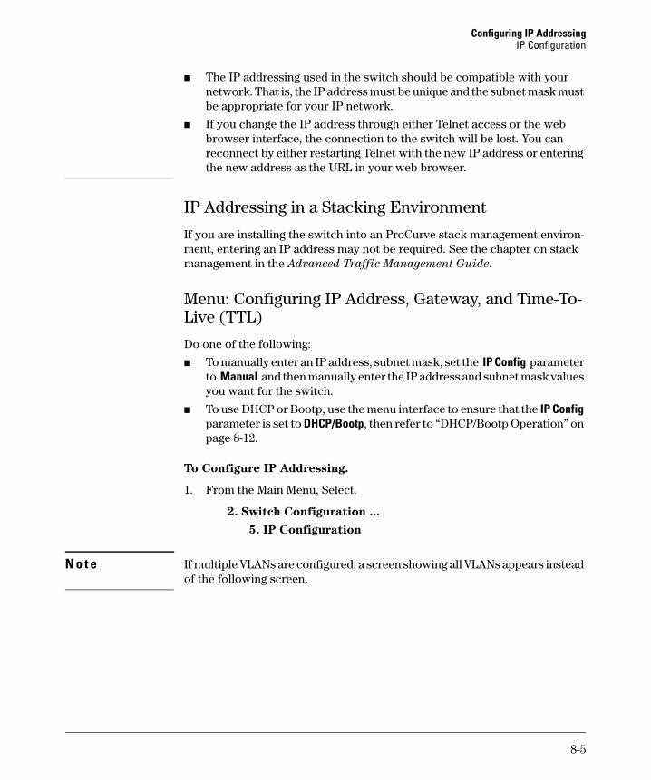
Configuring IP Addressing IP Configuration
■ The IP addressing used in the switch should be compatible with your network. That is, the IP address must be unique and the subnet mask must be appropriate for your IP network.
■ If you change the IP address through either Telnet access or the web browser interface, the connection to the switch will be lost. You can reconnect by either restarting Telnet with the new IP address or entering the new address as the URL in your web browser.
IP Addressing in a Stacking Environment
If you are installing the switch into an ProCurve stack management environment, entering an IP address may not be required. See the chapter on stack management in the Advanced Traffic Management Guide.
Menu: Configuring IP Address, Gateway, and Time-To-Live (TTL)
Do one of the following:
■ To manually enter an IP address, subnet mask, set the IP Config parameter to Manual and then manually enter the IP address and subnet mask values you want for the switch.
■ To use DHCP or Bootp, use the menu interface to ensure that the IP Config parameter is set to DHCP/Bootp, then refer to “DHCP/Bootp Operation” on page 8-12.
To Configure IP Addressing.
1. From the Main Menu, Select.
2. Switch Configuration ...
5. IP Configuration
N o t e If multiple VLANs are configured, a screen showing all VLANs appears instead of the following screen.
8-5
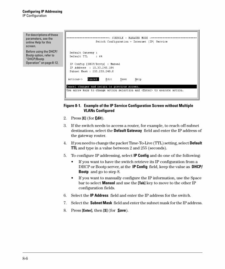
Configuring IP Addressing IP Configuration
For descriptions of these parameters, see the online Help for this screen.
Before using the DHCP/ Bootp option, refer to “DHCP/Bootp Operation” on page 8-12.
Figure 8-1. Example of the IP Service Configuration Screen without Multiple VLANs Configured
2. Press [E] (for Edit).
3. If the switch needs to access a router, for example, to reach off-subnet destinations, select the Default Gateway field and enter the IP address of the gateway router.
4. If you need to change the packet Time-To-Live (TTL) setting, select Default TTL and type in a value between 2 and 255 (seconds).
5. To configure IP addressing, select IP Config and do one of the following:
• If you want to have the switch retrieve its IP configuration from a DHCP or Bootp server, at the IP Config field, keep the value as DHCP/ Bootp and go to step 8.
• If you want to manually configure the IP information, use the Space bar to select Manual and use the [Tab] key to move to the other IP configuration fields.
6. Select the IP Address field and enter the IP address for the switch.
7. Select the Subnet Mask field and enter the subnet mask for the IP address.
8. Press [Enter], then [S] (for Save).
8-6
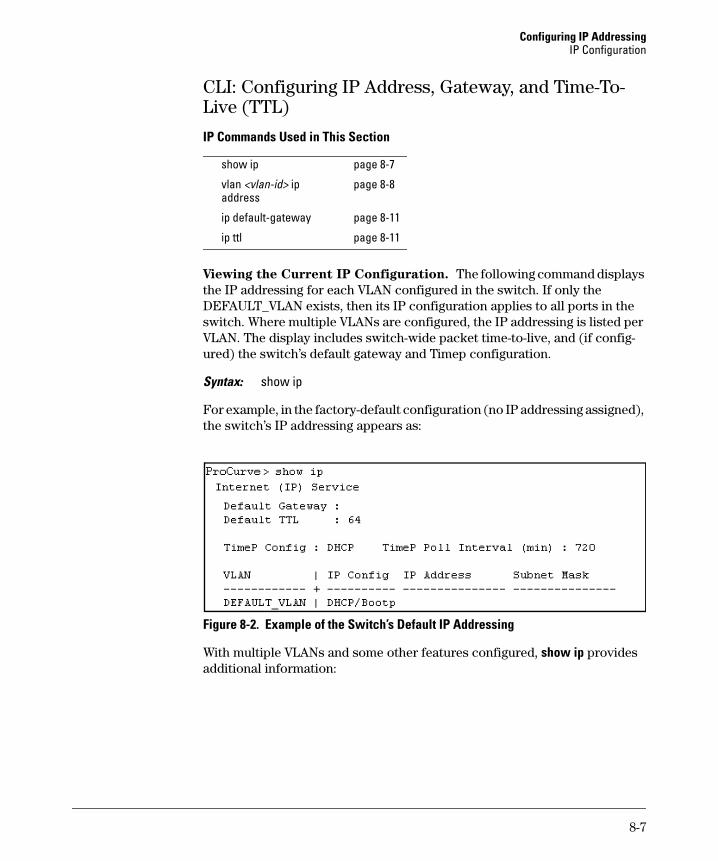
Configuring IP Addressing IP Configuration
CLI: Configuring IP Address, Gateway, and Time-To-Live (TTL)
IP Commands Used in This Section
show ip page 8-7
vlan <vlan-id> ip page 8-8address
ip default-gateway page 8-11
ip ttl page 8-11
Viewing the Current IP Configuration. The following command displays the IP addressing for each VLAN configured in the switch. If only the DEFAULT_VLAN exists, then its IP configuration applies to all ports in the switch. Where multiple VLANs are configured, the IP addressing is listed per VLAN. The display includes switch-wide packet time-to-live, and (if configured) the switch’s default gateway and Timep configuration.
Syntax: show ip
For example, in the factory-default configuration (no IP addressing assigned), the switch’s IP addressing appears as:
Figure 8-2. Example of the Switch’s Default IP Addressing
With multiple VLANs and some other features configured, show ip provides additional information:
8-7
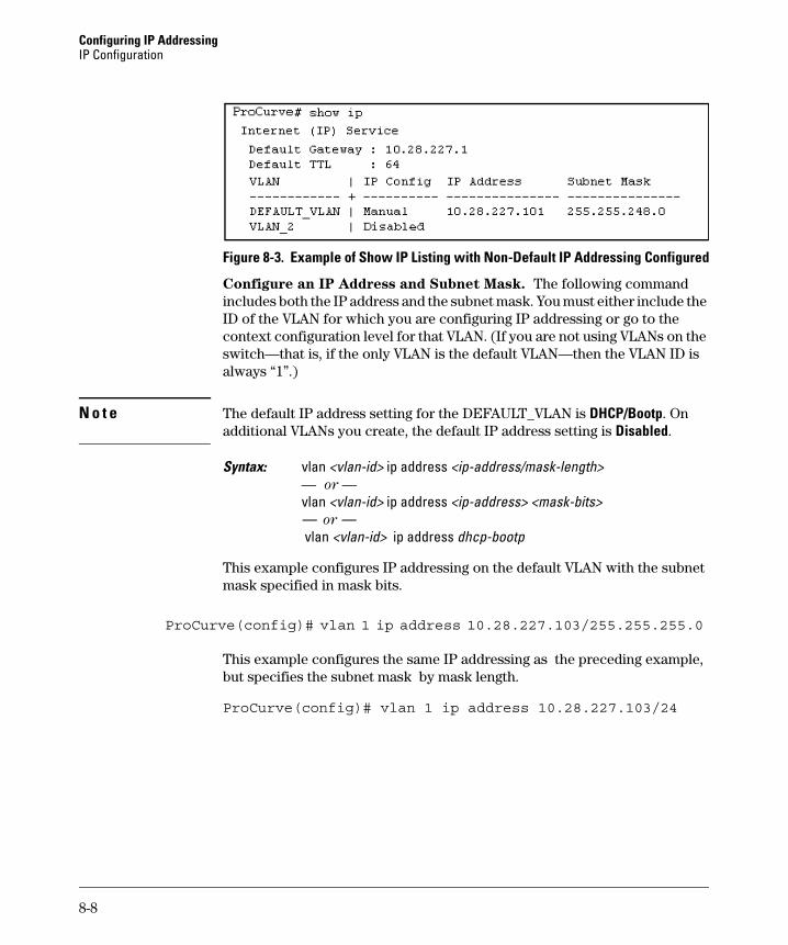
Configuring IP Addressing IP Configuration
Figure 8-3. Example of Show IP Listing with Non-Default IP Addressing Configured
Configure an IP Address and Subnet Mask. The following command includes both the IP address and the subnet mask. You must either include the ID of the VLAN for which you are configuring IP addressing or go to the context configuration level for that VLAN. (If you are not using VLANs on the switch—that is, if the only VLAN is the default VLAN—then the VLAN ID is always “1”.)
N o t e The default IP address setting for the DEFAULT_VLAN is DHCP/Bootp. On additional VLANs you create, the default IP address setting is Disabled.
Syntax: vlan <vlan-id> ip address <ip-address/mask-length> — or —
vlan <vlan-id> ip address <ip-address> <mask-bits> — or — vlan <vlan-id> ip address dhcp-bootp
This example configures IP addressing on the default VLAN with the subnet mask specified in mask bits.
ProCurve(config)# vlan 1 ip address 10.28.227.103/255.255.255.0
This example configures the same IP addressing as the preceding example, but specifies the subnet mask by mask length.
ProCurve(config)# vlan 1 ip address 10.28.227.103/24
8-8
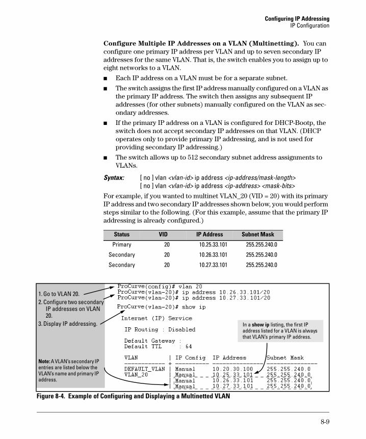
Configuring IP Addressing IP Configuration
Configure Multiple IP Addresses on a VLAN (Multinetting). You can configure one primary IP address per VLAN and up to seven secondary IP addresses for the same VLAN. That is, the switch enables you to assign up to eight networks to a VLAN.
■ Each IP address on a VLAN must be for a separate subnet.
■ The switch assigns the first IP address manually configured on a VLAN as the primary IP address. The switch then assigns any subsequent IP addresses (for other subnets) manually configured on the VLAN as secondary addresses.
■ If the primary IP address on a VLAN is configured for DHCP-Bootp, the switch does not accept secondary IP addresses on that VLAN. (DHCP operates only to provide primary IP addressing, and is not used for providing secondary IP addressing.)
■ The switch allows up to 512 secondary subnet address assignments to VLANs.
Syntax: [ no ] vlan <vlan-id> ip address <ip-address/mask-length> [ no ] vlan <vlan-id> ip address <ip-address> <mask-bits>
For example, if you wanted to multinet VLAN_20 (VID = 20) with its primary IP address and two secondary IP addresses shown below, you would perform steps similar to the following. (For this example, assume that the primary IP addressing is already configured.)
Status VID Subnet MaskIP Address
Primary 20 10.25.33.101 255.255.240.0
Secondary 20 10.26.33.101 255.255.240.0
Secondary 20 10.27.33.101 255.255.240.0
lii
In a show ip listing, the first IP
1. Go to VLAN 20. 2. Configure two secondary
IP addresses on VLAN 20.
3. Display IP addressing.
Note: A VLAN’s secondary IP entries are sted below the VLAN’s name and pr mary IP address.
address listed for a VLAN is always that VLAN’s primary IP address.
Figure 8-4. Example of Configuring and Displaying a Multinetted VLAN
8-9
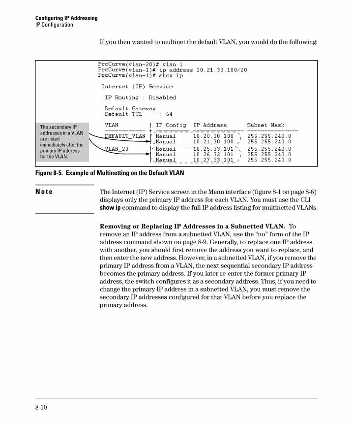
Configuring IP Addressing IP Configuration
If you then wanted to multinet the default VLAN, you would do the following:
isted
The secondary IP addresses in a VLAN are limmediately after the primary IP address for the VLAN.
Figure 8-5. Example of Multinetting on the Default VLAN
N o t e The Internet (IP) Service screen in the Menu interface (figure 8-1 on page 8-6) displays only the primary IP address for each VLAN. You must use the CLI show ip command to display the full IP address listing for multinetted VLANs.
Removing or Replacing IP Addresses in a Subnetted VLAN. To remove an IP address from a subnetted VLAN, use the “no” form of the IP address command shown on page 8-9. Generally, to replace one IP address with another, you should first remove the address you want to replace, and then enter the new address. However, in a subnetted VLAN, if you remove the primary IP address from a VLAN, the next sequential secondary IP address becomes the primary address. If you later re-enter the former primary IP address, the switch configures it as a secondary address. Thus, if you need to change the primary IP address in a subnetted VLAN, you must remove the secondary IP addresses configured for that VLAN before you replace the primary address.
8-10
Configuring IP Addressing IP Configuration
Configure the Optional Default Gateway. Using the Global configuration level, you can assign one default gateway to the switch.
Syntax: ip default-gateway <ip-address>
For example:
ProCurve(config)# ip default-gateway 10.28.227.115
Note The switch uses the IP default gateway only while operating as a Layer 2 device. While routing is enabled on the switch, the IP default gateway is not used. Thus, to avoid loss of Telnet access to off-subnet management stations, you should use the ip route command to configure a static (default) route before enabling routing. Refer to chapter 16, “IP Routing Features”, for more information.
Configure Time-To-Live (TTL). Use this command at the Global config prompt to set the time that a packet outbound from the switch can exist on the network. The default setting is 64 seconds.
Syntax: ip ttl <number-of-seconds>
ProCurve(config)# ip ttl 60
In the CLI, you can execute this command only from the global configuration level. The TTL range is 2 - 255 seconds.
Web: Configuring IP Addressing
You can use the web browser interface to access IP addressing only if the switch already has an IP address that is reachable through your network.
1. Click on the Configuration tab.
2. Click on [IP Configuration].
3. If you need further information on using the web browser interface, click on [?] to access the web-based help available for the Switch 2512/2524.
How IP Addressing Affects Switch Operation
Without an IP address and subnet mask compatible with your network, the switch can be managed only through a direct terminal device connection to the Console RS-232 port. You can use direct-connect console access to take advantage of features that do not depend on IP addressing. However, to realize the full performance capabilities HP proactive networking offers through the
8-11
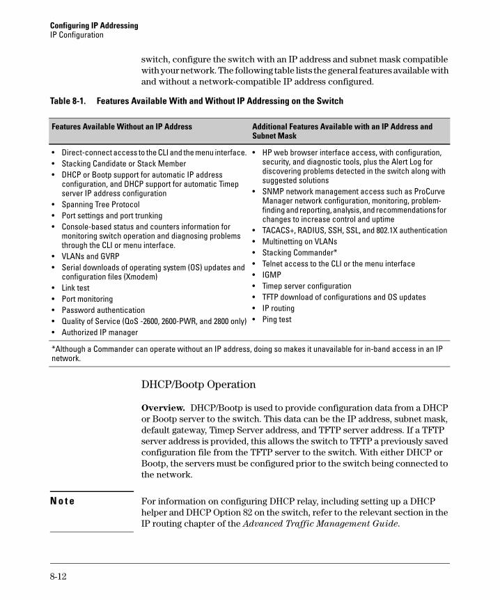
Configuring IP Addressing IP Configuration
switch, configure the switch with an IP address and subnet mask compatible with your network. The following table lists the general features available with and without a network-compatible IP address configured.
Table 8-1. Features Available With and Without IP Addressing on the Switch
Subnet Mask Features Available Without an IP Address Additional Features Available with an IP Address and
• Direct-connect access to the CLI and the menu interface. • Stacking Candidate or Stack Member • DHCP or Bootp support for automatic IP address
configuration, and DHCP support for automatic Timep server IP address configuration
• Spanning Tree Protocol • Port settings and port trunking • Console-based status and counters information for
monitoring switch operation and diagnosing problems through the CLI or menu interface.
• VLANs and GVRP • Serial downloads of operating system (OS) updates and
configuration files (Xmodem) • Link test • Port monitoring • Password authentication • Quality of Service (QoS -2600, 2600-PWR, and 2800 only) • Authorized IP manager
• HP web browser interface access, with configuration, security, and diagnostic tools, plus the Alert Log for discovering problems detected in the switch along with suggested solutions
• SNMP network management access such as ProCurve Manager network configuration, monitoring, problem-finding and reporting, analysis, and recommendations for changes to increase control and uptime
• TACACS+, RADIUS, SSH, SSL, and 802.1X authentication • Multinetting on VLANs • Stacking Commander* • Telnet access to the CLI or the menu interface • IGMP • Timep server configuration • TFTP download of configurations and OS updates • IP routing • Ping test
*Although a Commander can operate without an IP address, doing so makes it unavailable for in-band access in an IP network.
DHCP/Bootp Operation
Overview. DHCP/Bootp is used to provide configuration data from a DHCP or Bootp server to the switch. This data can be the IP address, subnet mask, default gateway, Timep Server address, and TFTP server address. If a TFTP server address is provided, this allows the switch to TFTP a previously saved configuration file from the TFTP server to the switch. With either DHCP or Bootp, the servers must be configured prior to the switch being connected to the network.
N o t e For information on configuring DHCP relay, including setting up a DHCP helper and DHCP Option 82 on the switch, refer to the relevant section in the IP routing chapter of the Advanced Traffic Management Guide.
8-12
Configuring IP Addressing IP Configuration
The DHCP/Bootp Process. Whenever the IP Config parameter in the switch or in an individual VLAN in the switch is configured to DHCP/Bootp (the default), or when the switch is rebooted with this configuration:
1. DHCP/Bootp requests are automatically broadcast on the local network. (The switch sends one type of request to which either a DHCP or Bootp server can respond.)
2. When a DHCP or Bootp server receives the request, it replies with a previously configured IP address and subnet mask for the switch. The switch also receives an IP Gateway address if the server has been configured to provide one. In the case of Bootp, the server must first be configured with an entry that has the MAC address of the switch. (To determine the switch’s MAC address, see Appendix D, "MAC Address Management". The switch properly handles replies from either type of server. If multiple replies are returned, the switch will use the first reply.)
N o t e If you manually configure a gateway on the switch, it will ignore any gateway address received via DHCP or Bootp.
If the switch is initially configured for DHCP/Bootp operation (the default), or if it is rebooted with this configuration, it immediately begins sending request packets on the network. If the switch does not receive a reply to its DHCP/Bootp requests, it continues to periodically send request packets, but with decreasing frequency. Thus, if a DHCP or Bootp server is not available or accessible to the switch when DHCP/Bootp is first configured, the switch may not immediately receive the desired configuration. After verifying that the server has become accessible to the switch, reboot the switch to re-start the process immediately.
DHCP Operation. Depending on how the DHCP server is configured, the switch may receive an ip address that is temporarily leased. Periodically the switch may be required to renew its lease of the IP configuration. Thus, the IP addressing provided by the server may be different each time the switch reboots or renews its configuration from the server. However, you can fix the address assignment for the switch by doing either of the following:
■ Configure the server to issue an “infinite” lease.
■ Using the switch’s MAC address as an identifier, configure the server with a “Reservation” so that it will always assign the same IP address to the switch. (For MAC address information, refer to Appendix D, "MAC Address Management".)
For more information on either of these procedures, refer to the documentation provided with the DHCP server.
8-13
Configuring IP Addressing IP Configuration
Bootp Operation. When a Bootp server receives a request it searches its Bootp database for a record entry that matches the MAC address in the Bootp request from the switch. If a match is found, the configuration data in the associated database record is returned to the switch. For many Unix systems, the Bootp database is contained in the /etc/bootptab file. In contrast to DHCP operation, Bootp configurations are always the same for a specific receiving device. That is, the Bootp server replies to a request with a configuration previously stored in the server and designated for the requesting device.
Bootp Database Record Entries. A minimal entry in the Bootp table file /etc/bootptab to update an IP address and subnet mask to the switch or a VLAN configured in the switch would be similar to this entry:
j4108switch:\ ht=ether:\ ha=0030c1123456:\ ip=10.66.77.88:\ sm=255.255.248.0:\ gw=10.66.77.1:\ hn:\ vm=rfc1048
An entry in the Bootp table file /etc/bootptab to tell the switch or VLAN where to obtain a configuration file download would be similar to this entry:
j4108switch:\ ht=ether:\ ha=0030c1123456:\ ip=10.66.77.88:\ sm=255.255.248.0:\ gw=10.66.77.1:\ lg=10.22.33.44:\ T144=”switch.cfg”:\vm=rfc1048
where:
j4108switch is a user-defined symbolic name to help you find the correct section of the bootptab file. If you have multiple switches that will be using Bootp to get their IP configuration, you should use a unique symbolic name for each switch.
ht is the “hardware type”. For the switches covered in this guide, set this to ether (for Ethernet). This tag must precede the ha tag.
ha is the “hardware address”. Use the switch's (or VLAN's) 12-digit MAC address.
ip is the IP address to be assigned to the switch (or VLAN).
sm is the subnet mask of the subnet in which the switch (or VLAN) is installed.
gw is the IP address of the default gateway.
8-14
Configuring IP Addressing IP Configuration
lg TFTP server address (source of final configuration file)
T144 is the vendor-specific “tag” identifying the configuration file to download.
vm is a required entry that specifies the Bootp report format. For the switches described in this guide, set this parameter to rfc1048.
N o t e The above Bootp table entry is a sample that will work for the switch when the appropriate addresses and file names are used.
Network Preparations for Configuring DHCP/Bootp
In its default configuration, the switch is configured for DHCP/Bootp operation. However, the DHCP/Bootp feature will not acquire IP addressing for the switch unless the following tasks have already been completed:
■ For Bootp operation:
• A Bootp database record has already been entered into an appropriate Bootp server.
• The necessary network connections are in place
• The Bootp server is accessible from the switch
■ For DHCP operation:
• A DHCP scope has been configured on the appropriate DHCP server.
• The necessary network connections are in place
• A DHCP server is accessible from the switch
N o t e Designating a primary VLAN other than the default VLAN affects the switch’s use of information received via DHCP/Bootp. For more on this topic, see the chapter on Virtual LANs in the Advanced Traffic Management Guide.
After you reconfigure or reboot the switch with DHCP/Bootp enabled in a network providing DHCP/Bootp service, the switch does the following:
■ Receives an IP address and subnet mask and, if configured in the server, a gateway IP address and the address of a Timep server.
■ If the DHCP/Bootp reply provides information for downloading a configuration file, the switch uses TFTP to download the file from the designated source, then reboots itself. (This assumes that the switch or VLAN has connectivity to the TFTP file server specified in the reply, that the configuration file is correctly named, and that the configuration file exists in the TFTP directory.)
8-15
Configuring IP Addressing IP Preserve: Retaining VLAN-1 IP Addressing Across Configuration File Downloads
IP Preserve: Retaining VLAN-1 IP Addressing Across Configuration File Downloads
IP Preserve enables you to copy a configuration file to multiple switches that use the same operating-system software while retaining the individual IP address and subnet mask on VLAN 1 in each switch, and the Gateway IP address assigned to the switch. This enables you to distribute the same configuration file to multiple switches without overwriting their individual IP addresses.
Operating Rules for IP Preserve
When ip preserve is entered as the last line in a configuration file stored on a TFTP server:
■ If the switch’s current IP address for VLAN 1 was not configured by DHCP/ Bootp, IP Preserve retains the switch’s current IP address, subnet mask, and IP gateway address when the switch downloads the file and reboots. The switch adopts all other configuration parameters in the configuration file into the startup-config file.
■ If the switch’s current IP addressing for VLAN 1 is from a DHCP server, IP Preserve is suspended. In this case, whatever IP addressing the configuration file specifies is implemented when the switch downloads the file and reboots. If the file includes DHCP/Bootp as the IP addressing source for VLAN 1, the switch will configure itself accordingly and use DHCP/ Bootp. If instead, the file includes a dedicated IP address and subnet mask for VLAN 1 and a specific gateway IP address, then the switch will implement these settings in the startup-config file.
■ The ip preserve statement does not appear in show config listings. To verify IP Preserve in a configuration file, open the file in a text editor and view the last line. For an example of implementing IP Preserve in a configuration file, see figure 8-6, below.
To set up IP Preserve, enter the ip preserve statement at the end of a configuration file. (Note that you do not execute IP Preserve by entering a command from the CLI).
8-16
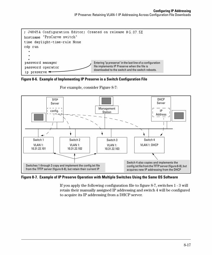
Configuring IP Addressing IP Preserve: Retaining VLAN-1 IP Addressing Across Configuration File Downloads
Figure 8-6. Example of Implementing IP Preserve in a Switch Configuration File
For example, consider Figure 8-7:
Figure 8-7. Example of IP Preserve Operation with Multiple Switches Using the Same OS Software
If you apply the following configuration file to figure 8-7, switches 1 - 3 will retain their manually assigned IP addressing and switch 4 will be configured to acquire its IP addressing from a DHCP server.
ing "il
Enter p preserve" in the last line of a configuration file imp ements IP Preserve when the file is downloaded to the switch and the switch reboots.
Switch 3Switch 1
Server
IP
i i l
Station
Switch 4
VLAN 1: DHCP VLAN 1: 10.31.22.103
VLAN 1: 10.31.22.101
DHCP
Switch 2
VLAN 1: 10.31.22.102
config. Address
Switches 1 through 3 copy and implement the config.txt file from the TFTP server (figure 8-8), but retain their current IP
Switch 4 also cop es and mp ements the config.txt file from the TFTP server (figure 8-8), but acquires new IP addressing from the DHCP
TFTP Server
Management
8-17
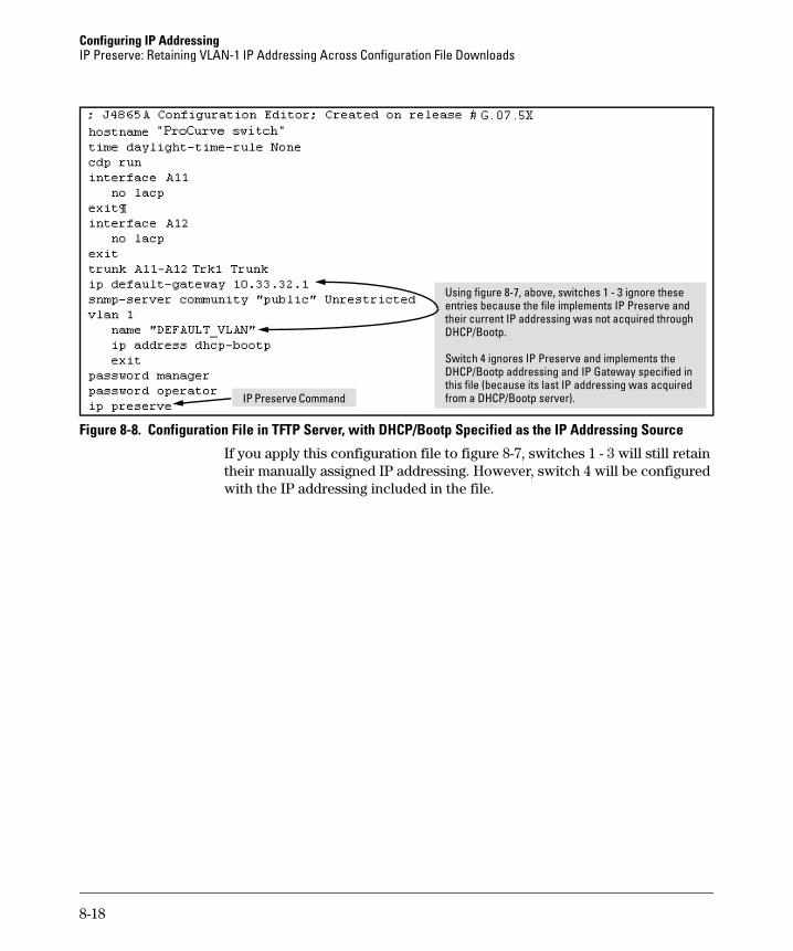
Configuring IP Addressing IP Preserve: Retaining VLAN-1 IP Addressing Across Configuration File Downloads
entri l
i in
Using figure 8-7, above, switches 1 - 3 ignore these es because the file imp ements IP Preserve and
their current IP addressing was not acquired through DHCP/Bootp.
Switch 4 ignores IP Preserve and implements the DHCP/Bootp addressing and IP Gateway spec fied this file (because its last IP addressing was acquired from a DHCP/Bootp server). IP Preserve Command
Figure 8-8. Configuration File in TFTP Server, with DHCP/Bootp Specified as the IP Addressing Source
If you apply this configuration file to figure 8-7, switches 1 - 3 will still retain their manually assigned IP addressing. However, switch 4 will be configured with the IP addressing included in the file.
8-18
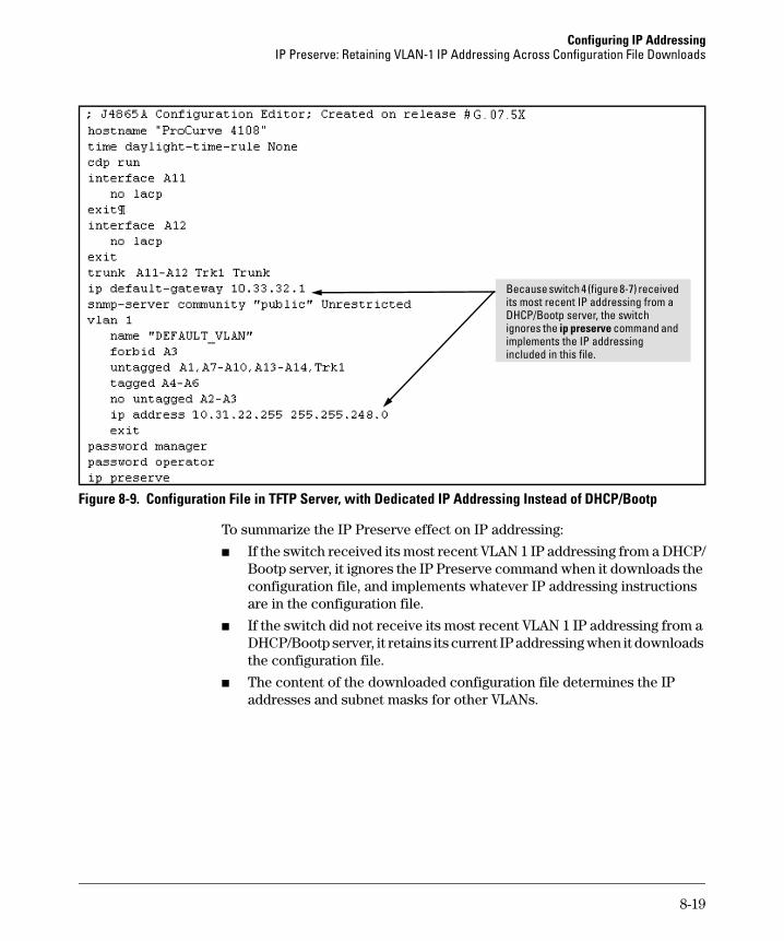
Configuring IP Addressing IP Preserve: Retaining VLAN-1 IP Addressing Across Configuration File Downloads
i
incl
Because switch 4 (figure 8-7) received ts most recent IP addressing from a
DHCP/Bootp server, the switch ignores the ip preserve command and implements the IP addressing
uded in this file.
Figure 8-9. Configuration File in TFTP Server, with Dedicated IP Addressing Instead of DHCP/Bootp
To summarize the IP Preserve effect on IP addressing:
■ If the switch received its most recent VLAN 1 IP addressing from a DHCP/ Bootp server, it ignores the IP Preserve command when it downloads the configuration file, and implements whatever IP addressing instructions are in the configuration file.
■ If the switch did not receive its most recent VLAN 1 IP addressing from a DHCP/Bootp server, it retains its current IP addressing when it downloads the configuration file.
■ The content of the downloaded configuration file determines the IP addresses and subnet masks for other VLANs.
8-19

Configuring IP Addressing IP Preserve: Retaining VLAN-1 IP Addressing Across Configuration File Downloads
— This page is intentionally unused. —
8-20
9
Time Protocols
Contents
Overview . . . . . . . . . . . . . . . . . . . . . . . . . . . . . . . . . . . . . . . . . . . . . . . . . . . . . . 9-2
TimeP Time Synchronization . . . . . . . . . . . . . . . . . . . . . . . . . . . . . . . . . . 9-2
SNTP Time Synchronization . . . . . . . . . . . . . . . . . . . . . . . . . . . . . . . . . . 9-2
Overview: Selecting a Time Synchronization Protocol or Turning OffTime Protocol Operation . . . . . . . . . . . . . . . . . . . . . . . . . . . . . . . . . . . . . . . . . 9-3
General Steps for Running a Time Protocol on the Switch . . . . . . . . . 9-3
Disabling Time Synchronization . . . . . . . . . . . . . . . . . . . . . . . . . . . . . . . 9-4
SNTP: Viewing, Selecting, and Configuring . . . . . . . . . . . . . . . . . . . . . . . . . 9-4
Menu: Viewing and Configuring SNTP . . . . . . . . . . . . . . . . . . . . . . . . . . 9-5
CLI: Viewing and Configuring SNTP . . . . . . . . . . . . . . . . . . . . . . . . . . . . 9-8Viewing the Current SNTP Configuration . . . . . . . . . . . . . . . . . . . . 9-8Configuring (Enabling or Disabling) the SNTP Mode . . . . . . . . . . 9-9
TimeP: Viewing, Selecting, and Configuring . . . . . . . . . . . . . . . . . . . . . . . . 9-14
Menu: Viewing and Configuring TimeP . . . . . . . . . . . . . . . . . . . . . . . . 9-15
CLI: Viewing and Configuring TimeP . . . . . . . . . . . . . . . . . . . . . . . . . . 9-16Viewing the Current TimeP Configuration . . . . . . . . . . . . . . . . . . 9-17Configuring (Enabling or Disabling) the TimeP Mode . . . . . . . . 9-18
SNTP Unicast Time Polling with Multiple SNTP Servers . . . . . . . . . . . . . 9-21
Address Prioritization . . . . . . . . . . . . . . . . . . . . . . . . . . . . . . . . . . . . . . . 9-22
Adding and Deleting SNTP Server Addresses . . . . . . . . . . . . . . . . . . . 9-22
Menu Interface Operation with Multiple SNTP Server Addresses Configured . . . . . . . . . . . . . . . . . . . . . . . . . . . . . . . . . . . . . . . . . . . . . . . . 9-24
SNTP Messages in the Event Log . . . . . . . . . . . . . . . . . . . . . . . . . . . . . . . . . 9-24
9-1
Time Protocols Overview
Overview
This chapter describes:
■ SNTP Time Protocol Operation
■ Timep Time Protocol Operation
Using time synchronization ensures a uniform time among inter operating devices. This helps you to manage and troubleshoot switch operation by attaching meaningful time data to event and error messages.
The switch offers TimeP and SNTP (Simple Network Time Protocol) and a timesync command for changing the time protocol selection (or turning off time protocol operation).
Notes ■ Although you can create and save configurations for both time proto
cols without conflicts, the switch allows only one active time protocol at any time.
■ In the factory-default configuration, the time synchronization option is set to TimeP, with the TimeP mode itself set to Disabled.
TimeP Time Synchronization
You can either manually assign the switch to use a TimeP server or use DHCP to assign the TimeP server. In either case, the switch can get its time synchronization updates from only one, designated Timep server. This option enhances security by specifying which time server to use.
SNTP Time Synchronization
SNTP provides two operating modes:
■ Broadcast Mode: The switch acquires time updates by accepting the time value from the first SNTP time broadcast detected. (In this case, the SNTP server must be configured to broadcast time updates to the network broadcast address. Refer to the documentation provided with your SNTP server application.) Once the switch detects a partic
9-2
Time Protocols Overview: Selecting a Time Synchronization Protocol or Turning Off Time Protocol Operation
ular server, it ignores time broadcasts from other SNTP servers unless the configurable Poll Interval expires three consecutive times without an update received from the first-detected server.
Note To use Broadcast mode, the switch and the SNTP server must be in the same subnet.
■ Unicast Mode: The switch requests a time update from the configured SNTP server. (You can configure one server using the menu interface, or up to three servers using the CLI sntp server command.) This option provides increased security over the Broadcast mode by specifying which time server to use instead of using the first one detected through a broadcast.
Overview: Selecting a Time Synchronization Protocol or Turning Off Time Protocol Operation
General Steps for Running a Time Protocol on the Switch
1. Select the time synchronization protocol: SNTP or TimeP (the default).
2. Enable the protocol. The choices are:
• SNTP: Broadcast or Unicast
• TimeP: DHCP or Manual
3. Configure the remaining parameters for the time protocol you selected.
The switch retains the parameter settings for both time protocols even if you change from one protocol to the other. Thus, if you select a time protocol, the switch uses the parameters you last configured for the selected protocol.
9-3
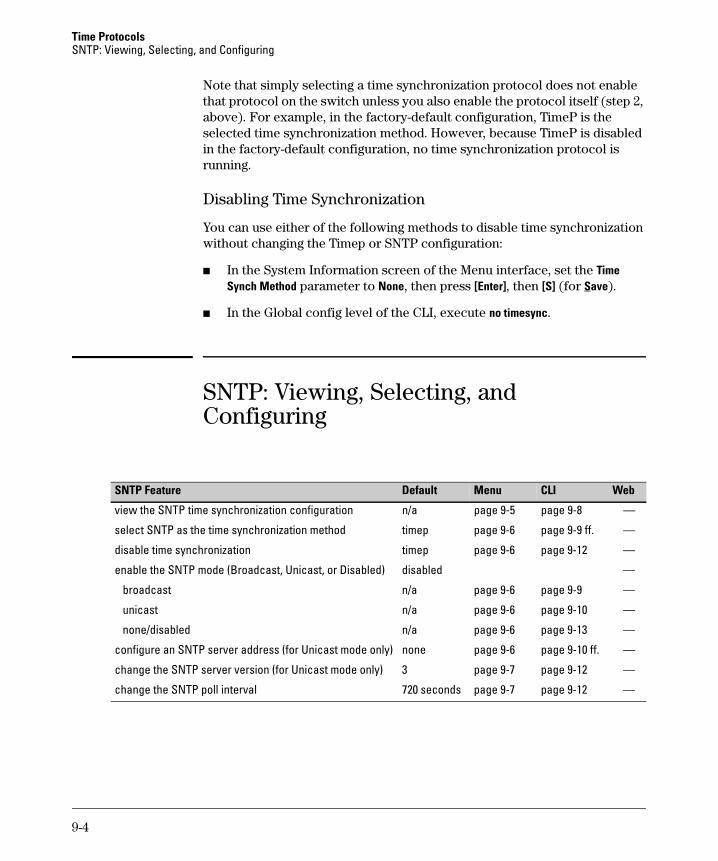
Time Protocols SNTP: Viewing, Selecting, and Configuring
Note that simply selecting a time synchronization protocol does not enable that protocol on the switch unless you also enable the protocol itself (step 2, above). For example, in the factory-default configuration, TimeP is the selected time synchronization method. However, because TimeP is disabled in the factory-default configuration, no time synchronization protocol is running.
Disabling Time Synchronization
You can use either of the following methods to disable time synchronization without changing the Timep or SNTP configuration:
■ In the System Information screen of the Menu interface, set the Time Synch Method parameter to None, then press [Enter], then [S] (for Save).
■ In the Global config level of the CLI, execute no timesync.
SNTP: Viewing, Selecting, and Configuring
SNTP Feature Default Menu
page 9-5 page 9-8 —
CLI Web
view the SNTP time synchronization configuration n/a
select SNTP as the time synchronization method timep page 9-6 page 9-9 ff. —
disable time synchronization timep page 9-6 page 9-12 —
enable the SNTP mode (Broadcast, Unicast, or Disabled) disabled —
broadcast n/a page 9-6 page 9-9 —
unicast n/a page 9-6 page 9-10 —
none/disabled n/a page 9-6 page 9-13 —
configure an SNTP server address (for Unicast mode only) none page 9-6 page 9-10 ff. —
change the SNTP server version (for Unicast mode only) 3 page 9-7 page 9-12 —
change the SNTP poll interval 720 seconds page 9-7 page 9-12 —
9-4
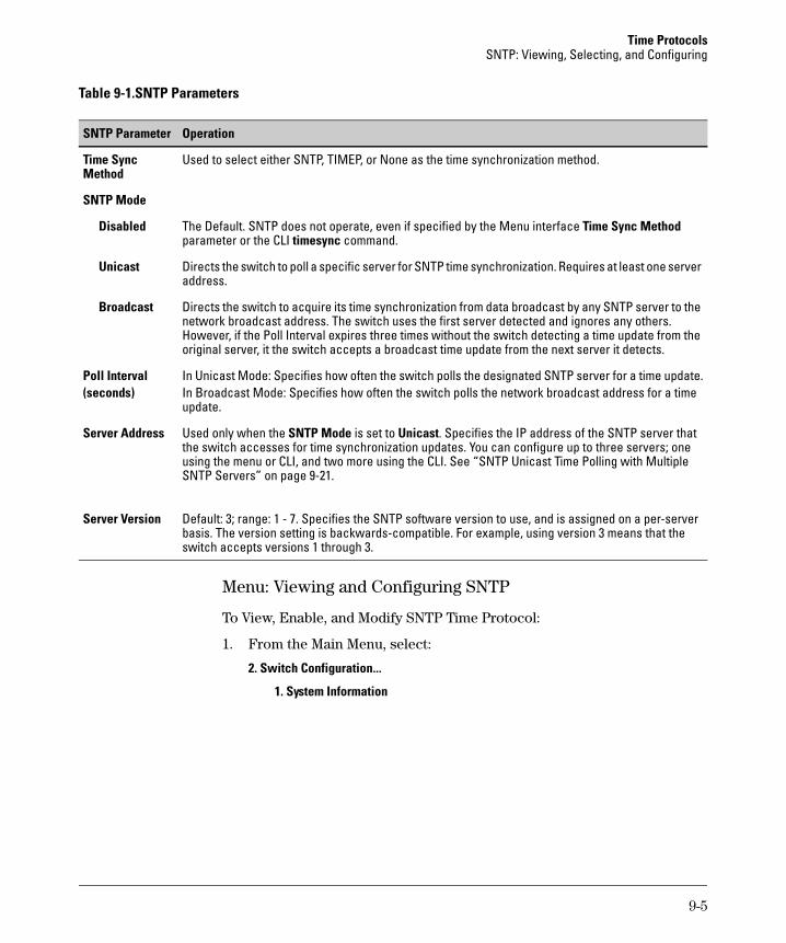
Time Protocols SNTP: Viewing, Selecting, and Configuring
Table 9-1.SNTP Parameters
OperationSNTP Parameter
Time Sync Used to select either SNTP, TIMEP, or None as the time synchronization method. Method
SNTP Mode
Disabled The Default. SNTP does not operate, even if specified by the Menu interface Time Sync Method parameter or the CLI timesync command.
Unicast Directs the switch to poll a specific server for SNTP time synchronization. Requires at least one server address.
Broadcast Directs the switch to acquire its time synchronization from data broadcast by any SNTP server to the network broadcast address. The switch uses the first server detected and ignores any others. However, if the Poll Interval expires three times without the switch detecting a time update from the original server, it the switch accepts a broadcast time update from the next server it detects.
Poll Interval In Unicast Mode: Specifies how often the switch polls the designated SNTP server for a time update. (seconds) In Broadcast Mode: Specifies how often the switch polls the network broadcast address for a time
update.
Server Address Used only when the SNTP Mode is set to Unicast. Specifies the IP address of the SNTP server that the switch accesses for time synchronization updates. You can configure up to three servers; one using the menu or CLI, and two more using the CLI. See “SNTP Unicast Time Polling with Multiple SNTP Servers” on page 9-21.
Server Version Default: 3; range: 1 - 7. Specifies the SNTP software version to use, and is assigned on a per-server basis. The version setting is backwards-compatible. For example, using version 3 means that the switch accepts versions 1 through 3.
Menu: Viewing and Configuring SNTP
To View, Enable, and Modify SNTP Time Protocol:
1. From the Main Menu, select:
2. Switch Configuration...
1. System Information
9-5
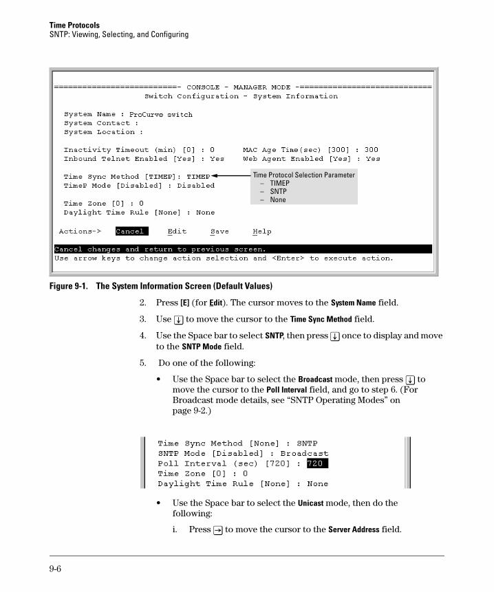
Time Protocols SNTP: Viewing, Selecting, and Configuring
Ti
–
me Protocol Selection Parameter – TIMEP – SNTP
None
Figure 9-1. The System Information Screen (Default Values)
2. Press [E] (for Edit). The cursor moves to the System Name field.
3. Use [v] to move the cursor to the Time Sync Method field.
4. Use the Space bar to select SNTP, then press [v] once to display and move to the SNTP Mode field.
5. Do one of the following:
• Use the Space bar to select the Broadcast mode, then press [v] to move the cursor to the Poll Interval field, and go to step 6. (For Broadcast mode details, see “SNTP Operating Modes” on page 9-2.)
• Use the Space bar to select the Unicast mode, then do the following:
i. Press [>] to move the cursor to the Server Address field.
9-6
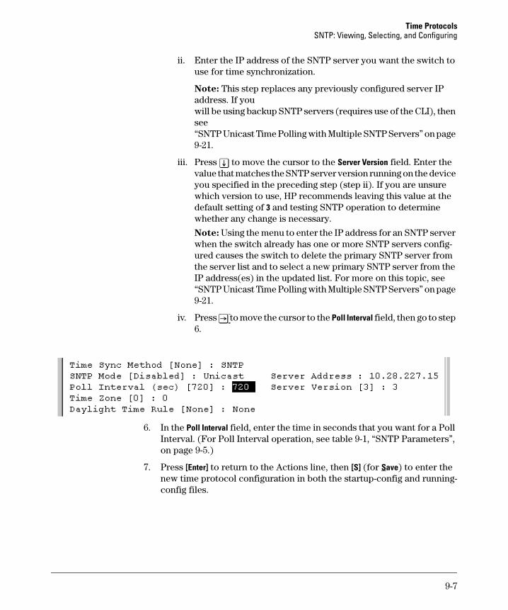
Time Protocols SNTP: Viewing, Selecting, and Configuring
ii. Enter the IP address of the SNTP server you want the switch to use for time synchronization.
Note: This step replaces any previously configured server IP address. If you will be using backup SNTP servers (requires use of the CLI), then see “SNTP Unicast Time Polling with Multiple SNTP Servers” on page 9-21.
iii. Press [v] to move the cursor to the Server Version field. Enter the value that matches the SNTP server version running on the device you specified in the preceding step (step ii). If you are unsure which version to use, HP recommends leaving this value at the default setting of 3 and testing SNTP operation to determine whether any change is necessary.
Note: Using the menu to enter the IP address for an SNTP server when the switch already has one or more SNTP servers configured causes the switch to delete the primary SNTP server from the server list and to select a new primary SNTP server from the IP address(es) in the updated list. For more on this topic, see “SNTP Unicast Time Polling with Multiple SNTP Servers” on page 9-21.
iv. Press [>] to move the cursor to the Poll Interval field, then go to step 6.
6. In the Poll Interval field, enter the time in seconds that you want for a Poll Interval. (For Poll Interval operation, see table 9-1, “SNTP Parameters”, on page 9-5.)
7. Press [Enter] to return to the Actions line, then [S] (for Save) to enter the new time protocol configuration in both the startup-config and runningconfig files.
9-7
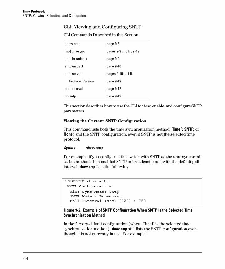
Time Protocols SNTP: Viewing, Selecting, and Configuring
CLI: Viewing and Configuring SNTP
CLI Commands Described in this Section
show sntp page 9-8
[no] timesync pages 9-9 and ff., 9-12
sntp broadcast page 9-9
sntp unicast page 9-10
sntp server pages 9-10 and ff.
Protocol Version page 9-12
poll-interval page 9-12
no sntp page 9-13
This section describes how to use the CLI to view, enable, and configure SNTP parameters.
Viewing the Current SNTP Configuration
This command lists both the time synchronization method (TimeP, SNTP, or None) and the SNTP configuration, even if SNTP is not the selected time protocol.
Syntax: show sntp
For example, if you configured the switch with SNTP as the time synchronization method, then enabled SNTP in broadcast mode with the default poll interval, show sntp lists the following:
Figure 9-2. Example of SNTP Configuration When SNTP Is the Selected Time Synchronization Method
In the factory-default configuration (where TimeP is the selected time synchronization method), show sntp still lists the SNTP configuration even though it is not currently in use. For example:
9-8
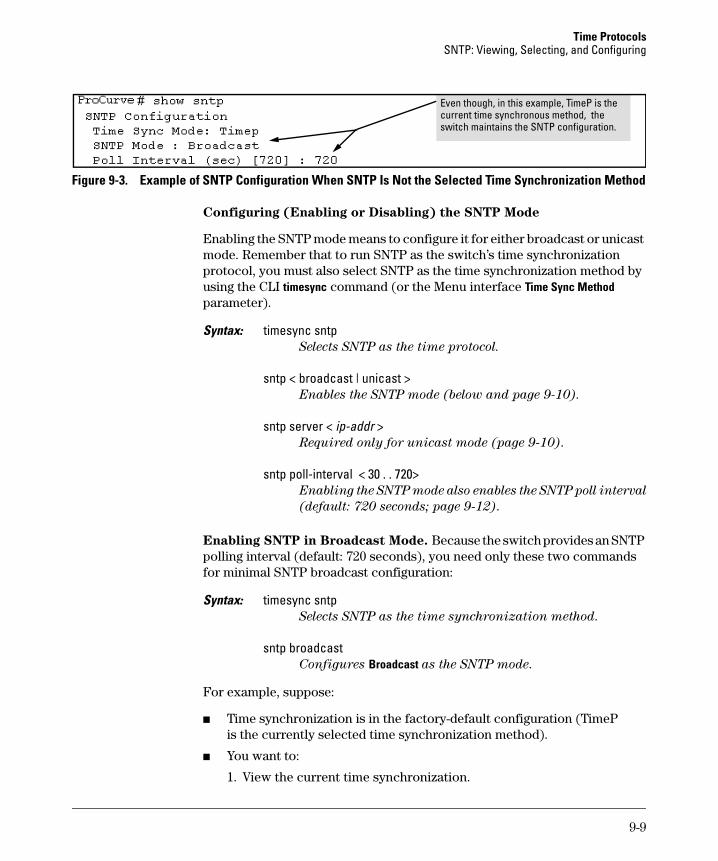
Time Protocols SNTP: Viewing, Selecting, and Configuring
Even though, in this example, TimeP is the current time synchronous method, the switch maintains the SNTP configuration.
Figure 9-3. Example of SNTP Configuration When SNTP Is Not the Selected Time Synchronization Method
Configuring (Enabling or Disabling) the SNTP Mode
Enabling the SNTP mode means to configure it for either broadcast or unicast mode. Remember that to run SNTP as the switch’s time synchronization protocol, you must also select SNTP as the time synchronization method by using the CLI timesync command (or the Menu interface Time Sync Method parameter).
Syntax: timesync sntp Selects SNTP as the time protocol.
sntp < broadcast | unicast > Enables the SNTP mode (below and page 9-10).
sntp server < ip-addr > Required only for unicast mode (page 9-10).
sntp poll-interval < 30 . . 720> Enabling the SNTP mode also enables the SNTP poll interval
(default: 720 seconds; page 9-12).
Enabling SNTP in Broadcast Mode. Because the switch provides an SNTP polling interval (default: 720 seconds), you need only these two commands for minimal SNTP broadcast configuration:
Syntax: timesync sntp Selects SNTP as the time synchronization method.
sntp broadcast Configures Broadcast as the SNTP mode.
For example, suppose:
■ Time synchronization is in the factory-default configuration (TimeP is the currently selected time synchronization method).
■ You want to:
1. View the current time synchronization.
9-9
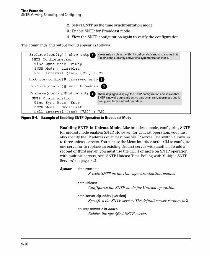
Time Protocols SNTP: Viewing, Selecting, and Configuring
2. Select SNTP as the time synchronization mode.
3. Enable SNTP for Broadcast mode.
4. View the SNTP configuration again to verify the configuration.
The commands and output would appear as follows:
1 show sntp displays the SNTP configuration and also shows that TimeP is the currently active time synchronization mode.
2
3
4 show sntp again displays the SNTP configuration and shows that SNTP is now the currently active time synchronization mode and is configured for broadcast operation.
4
Figure 9-4. Example of Enabling SNTP Operation in Broadcast Mode
Enabling SNTP in Unicast Mode. Like broadcast mode, configuring SNTP for unicast mode enables SNTP. However, for Unicast operation, you must also specify the IP address of at least one SNTP server. The switch allows up to three unicast servers. You can use the Menu interface or the CLI to configure one server or to replace an existing Unicast server with another. To add a second or third server, you must use the CLI. For more on SNTP operation with multiple servers, see “SNTP Unicast Time Polling with Multiple SNTP Servers” on page 9-21.
Syntax: timesync sntp Selects SNTP as the time synchronization method.
sntp unicast Configures the SNTP mode for Unicast operation.
sntp server <ip-addr> [version] Specifies the SNTP server. The default server version is 3.
no sntp server < ip-addr > Deletes the specified SNTP server.
9-10
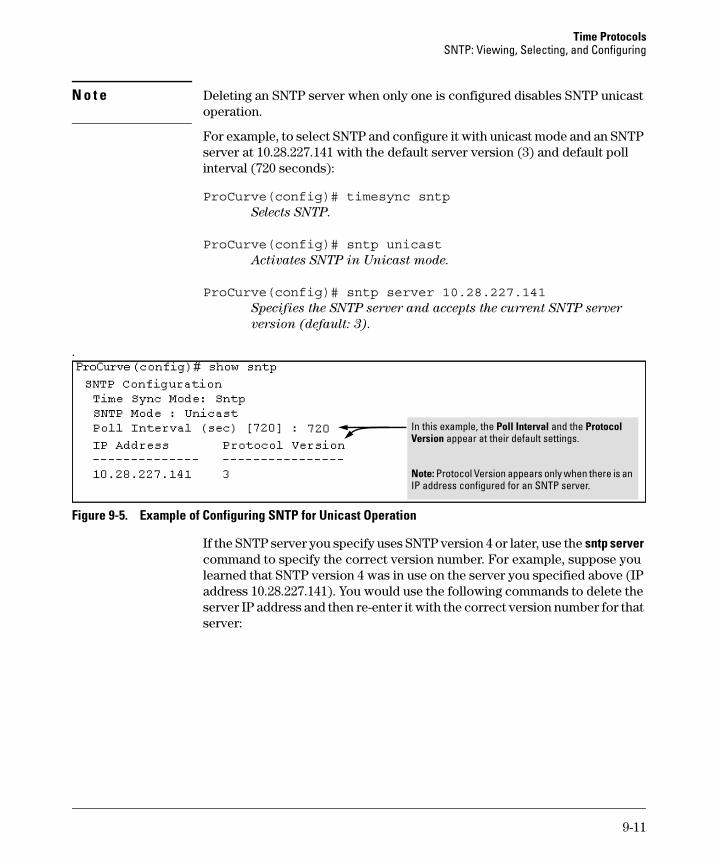
Time Protocols SNTP: Viewing, Selecting, and Configuring
N o t e Deleting an SNTP server when only one is configured disables SNTP unicast operation.
For example, to select SNTP and configure it with unicast mode and an SNTP server at 10.28.227.141 with the default server version (3) and default poll interval (720 seconds):
ProCurve(config)# timesync sntpSelects SNTP.
ProCurve(config)# sntp unicastActivates SNTP in Unicast mode.
ProCurve(config)# sntp server 10.28.227.141Specifies the SNTP server and accepts the current SNTP server
version (default: 3).
.
In this example, the Poll Interval and the Protocol Version appear at their default settings.
Note: Protocol Version appears only when there is an IP address configured for an SNTP server.
Figure 9-5. Example of Configuring SNTP for Unicast Operation
If the SNTP server you specify uses SNTP version 4 or later, use the sntp server command to specify the correct version number. For example, suppose you learned that SNTP version 4 was in use on the server you specified above (IP address 10.28.227.141). You would use the following commands to delete the server IP address and then re-enter it with the correct version number for that server:
9-11
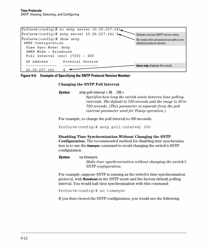
Time Protocols SNTP: Viewing, Selecting, and Configuring
Deletes unicast SNTP server entry.
Re-enters the unicast server with a non-default protocol version.
show sntp displays the result.
Figure 9-6. Example of Specifying the SNTP Protocol Version Number
Changing the SNTP Poll Interval.
Syntax: sntp poll-interval < 30 . . 720 > Specifies how long the switch waits between time polling
intervals. The default is 720 seconds and the range is 30 to
720 seconds. (This parameter is separate from the poll
interval parameter used for Timep operation.)
For example, to change the poll interval to 300 seconds:
ProCurve(config)# sntp poll-interval 300
Disabling Time Synchronization Without Changing the SNTP
Configuration. The recommended method for disabling time synchronization is to use the timesync command to avoid changing the switch’s SNTP configuration.
Syntax: no timesync Halts time synchronization without changing the switch’s
SNTP configuration
For example, suppose SNTP is running as the switch’s time synchronization protocol, with Broadcast as the SNTP mode and the factory-default polling interval. You would halt time synchronization with this command:
ProCurve(config)# no timesync
If you then viewed the SNTP configuration, you would see the following:
9-12
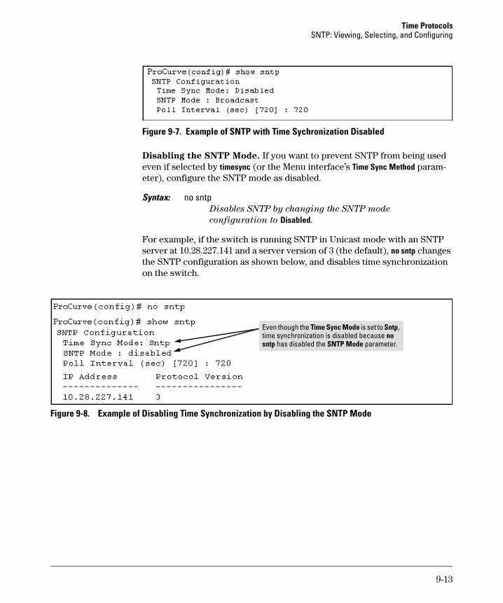
Time Protocols SNTP: Viewing, Selecting, and Configuring
Figure 9-7. Example of SNTP with Time Sychronization Disabled
Disabling the SNTP Mode. If you want to prevent SNTP from being used even if selected by timesync (or the Menu interface’s Time Sync Method parameter), configure the SNTP mode as disabled.
Syntax: no sntp Disables SNTP by changing the SNTP mode
configuration to Disabled.
For example, if the switch is running SNTP in Unicast mode with an SNTP server at 10.28.227.141 and a server version of 3 (the default), no sntp changes the SNTP configuration as shown below, and disables time synchronization on the switch.
Sntp, i no
sntp
Even though the Time Sync Mode is set to time synchronization s disabled because
has disabled the SNTP Mode parameter.
Figure 9-8. Example of Disabling Time Synchronization by Disabling the SNTP Mode
9-13
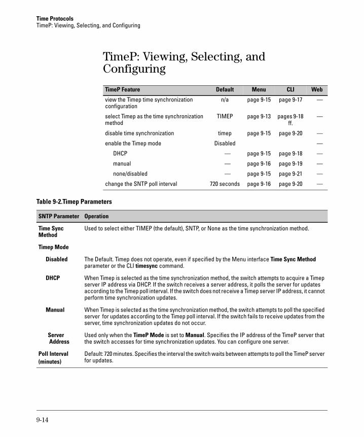
Time Protocols TimeP: Viewing, Selecting, and Configuring
TimeP: Viewing, Selecting, and Configuring
Default Menu CLITimeP Feature Web
view the Timep time synchronization n/a page 9-15 page 9-17 — configuration
select Timep as the time synchronization TIMEP page 9-13 pages 9-18 — method ff.
disable time synchronization timep page 9-15 page 9-20 —
enable the Timep mode Disabled —
DHCP — page 9-15 page 9-18 —
manual — page 9-16 page 9-19 —
none/disabled — page 9-15 page 9-21 —
change the SNTP poll interval 720 seconds page 9-16 page 9-20 —
Table 9-2.Timep Parameters
OperationSNTP Parameter
Time Sync Used to select either TIMEP (the default), SNTP, or None as the time synchronization method. Method
Timep Mode
Disabled The Default. Timep does not operate, even if specified by the Menu interface Time Sync Method parameter or the CLI timesync command.
DHCP When Timep is selected as the time synchronization method, the switch attempts to acquire a Timep server IP address via DHCP. If the switch receives a server address, it polls the server for updates according to the Timep poll interval. If the switch does not receive a Timep server IP address, it cannot perform time synchronization updates.
Manual When Timep is selected as the time synchronization method, the switch attempts to poll the specified server for updates according to the Timep poll interval. If the switch fails to receive updates from the server, time synchronization updates do not occur.
Server Used only when the TimeP Mode is set to Manual. Specifies the IP address of the TimeP server that Address the switch accesses for time synchronization updates. You can configure one server.
Poll Interval Default: 720 minutes. Specifies the interval the switch waits between attempts to poll the TimeP server (minutes) for updates.
9-14
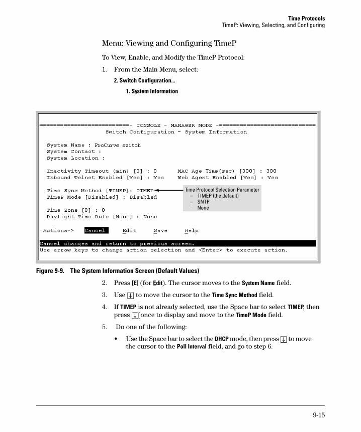
Time Protocols TimeP: Viewing, Selecting, and Configuring
Menu: Viewing and Configuring TimeP
To View, Enable, and Modify the TimeP Protocol:
1. From the Main Menu, select:
2. Switch Configuration...
1. System Information
Ti–
–
me Protocol Selection Parameter TIMEP (the default)
– SNTP None
Figure 9-9. The System Information Screen (Default Values)
2. Press [E] (for Edit). The cursor moves to the System Name field.
3. Use [v] to move the cursor to the Time Sync Method field.
4. If TIMEP is not already selected, use the Space bar to select TIMEP, then press [v] once to display and move to the TimeP Mode field.
5. Do one of the following:
• Use the Space bar to select the DHCP mode, then press [v] to move the cursor to the Poll Interval field, and go to step 6.
9-15
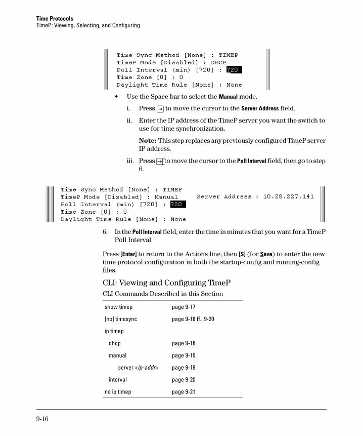
Time Protocols TimeP: Viewing, Selecting, and Configuring
• Use the Space bar to select the Manual mode.
i. Press [>] to move the cursor to the Server Address field.
ii. Enter the IP address of the TimeP server you want the switch to use for time synchronization.
Note: This step replaces any previously configured TimeP server IP address.
iii. Press [>] to move the cursor to the Poll Interval field, then go to step 6.
6. In the Poll Interval field, enter the time in minutes that you want for a TimeP Poll Interval.
Press [Enter] to return to the Actions line, then [S] (for Save) to enter the new time protocol configuration in both the startup-config and running-config files.
CLI: Viewing and Configuring TimeP CLI Commands Described in this Section
show timep page 9-17
[no] timesync page 9-18 ff., 9-20
ip timep
dhcp page 9-18
manual page 9-19
server <ip-addr> page 9-19
interval page 9-20
no ip timep page 9-21
9-16
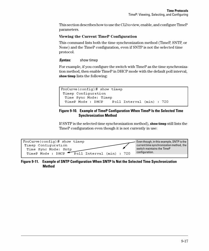
Time Protocols TimeP: Viewing, Selecting, and Configuring
This section describes how to use the CLI to view, enable, and configure TimeP parameters.
Viewing the Current TimeP Configuration
This command lists both the time synchronization method (TimeP, SNTP, or None) and the TimeP configuration, even if SNTP is not the selected time protocol.
Syntax: show timep
For example, if you configure the switch with TimeP as the time synchronization method, then enable TimeP in DHCP mode with the default poll interval, show timep lists the following:
Figure 9-10. Example of TimeP Configuration When TimeP Is the Selected Time Synchronization Method
If SNTP is the selected time synchronization method), show timep still lists the TimeP configuration even though it is not currently in use:
i
i i
Even though, n this example, SNTP is the current time synchronization method, the switch ma ntains the T meP configuration.
Figure 9-11. Example of SNTP Configuration When SNTP Is Not the Selected Time Synchronization Method
9-17
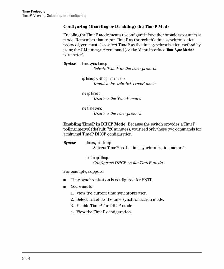
Time Protocols TimeP: Viewing, Selecting, and Configuring
Configuring (Enabling or Disabling) the TimeP Mode
Enabling the TimeP mode means to configure it for either broadcast or unicast mode. Remember that to run TimeP as the switch’s time synchronization protocol, you must also select TimeP as the time synchronization method by using the CLI timesync command (or the Menu interface Time Sync Method parameter).
Syntax: timesync timep Selects TimeP as the time protocol.
ip timep < dhcp | manual > Enables the selected TimeP mode.
no ip timep Disables the TimeP mode.
no timesync Disables the time protocol.
Enabling TimeP in DHCP Mode. Because the switch provides a TimeP polling interval (default: 720 minutes), you need only these two commands for a minimal TimeP DHCP configuration:
Syntax: timesync timep Selects TimeP as the time synchronization method.
ip timep dhcp Configures DHCP as the TimeP mode.
For example, suppose:
■ Time synchronization is configured for SNTP.
■ You want to:
1. View the current time synchronization.
2. Select TimeP as the time synchronization mode.
3. Enable TimeP for DHCP mode.
4. View the TimeP configuration.
9-18
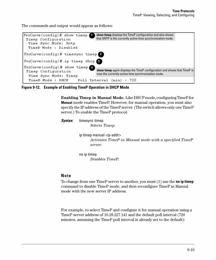
Time Protocols TimeP: Viewing, Selecting, and Configuring
The commands and output would appear as follows:
1 show timep displays the TimeP configuration and also shows that SNTP is the currently active time synchronization mode.
show timep again displays the TimeP configuration and shows that TimeP is now the currently active time synchronization mode.
2
3
4
Figure 9-12. Example of Enabling TimeP Operation in DHCP Mode
Enabling Timep in Manual Mode. Like DHCP mode, configuring TimeP for Manual mode enables TimeP. However, for manual operation, you must also specify the IP address of the TimeP server. (The switch allows only one TimeP server.) To enable the TimeP protocol:
Syntax: timesync timep Selects Timep.
ip timep manual <ip-addr> Activates TimeP in Manual mode with a specified TimeP
server.
no ip timep Disables TimeP.
Note To change from one TimeP server to another, you must (1) use the no ip timep command to disable TimeP mode, and then reconfigure TimeP in Manual mode with the new server IP address.
For example, to select TimeP and configure it for manual operation using a TimeP server address of 10.28.227.141 and the default poll interval (720 minutes, assuming the TimeP poll interval is already set to the default):
9-19
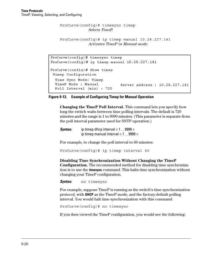
Time Protocols TimeP: Viewing, Selecting, and Configuring
ProCurve(config)# timesync timepSelects TimeP.
ProCurve(config)# ip timep manual 10.28.227.141Activates TimeP in Manual mode.
Figure 9-13. Example of Configuring Timep for Manual Operation
Changing the TimeP Poll Interval. This command lets you specify how long the switch waits between time polling intervals. The default is 720 minutes and the range is 1 to 9999 minutes. (This parameter is separate from the poll interval parameter used for SNTP operation.)
Syntax: ip timep dhcp interval < 1 . . 9999 >ip timep manual interval < 1 . . 9999 >
For example, to change the poll interval to 60 minutes:
ProCurve(config)# ip timep interval 60
Disabling Time Synchronization Without Changing the TimeP
Configuration. The recommended method for disabling time synchronization is to use the timesync command. This halts time synchronization without changing your TimeP configuration.
Syntax: no timesync
For example, suppose TimeP is running as the switch’s time synchronization protocol, with DHCP as the TimeP mode, and the factory-default polling interval. You would halt time synchronization with this command:
ProCurve(config)# no timesync
If you then viewed the TimeP configuration, you would see the following:
9-20
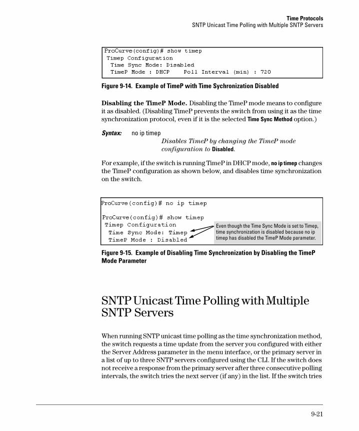
Time Protocols SNTP Unicast Time Polling with Multiple SNTP Servers
Figure 9-14. Example of TimeP with Time Sychronization Disabled
Disabling the TimeP Mode. Disabling the TimeP mode means to configure it as disabled. (Disabling TimeP prevents the switch from using it as the time synchronization protocol, even if it is the selected Time Sync Method option.)
Syntax: no ip timep Disables TimeP by changing the TimeP mode
configuration to Disabled.
For example, if the switch is running TimeP in DHCP mode, no ip timep changes the TimeP configuration as shown below, and disables time synchronization on the switch.
i iisabl
isabl i
Even though the T me Sync Mode is set to T mep, time synchronization is d ed because no ip timep has d ed the T meP Mode parameter.
Figure 9-15. Example of Disabling Time Synchronization by Disabling the TimeP Mode Parameter
SNTP Unicast Time Polling with Multiple SNTP Servers
When running SNTP unicast time polling as the time synchronization method, the switch requests a time update from the server you configured with either the Server Address parameter in the menu interface, or the primary server in a list of up to three SNTP servers configured using the CLI. If the switch does not receive a response from the primary server after three consecutive polling intervals, the switch tries the next server (if any) in the list. If the switch tries
9-21
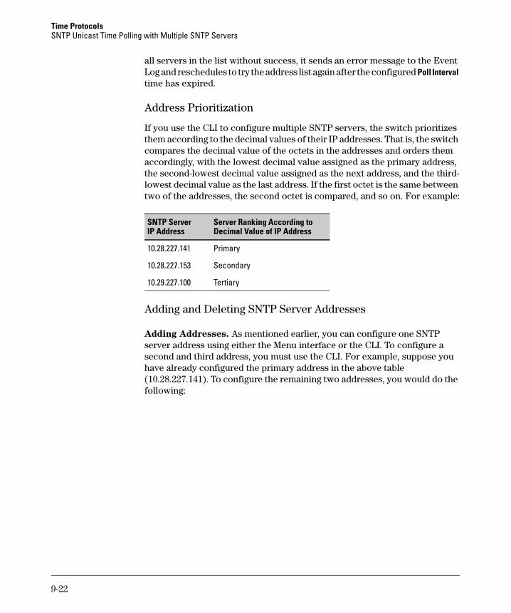
Time Protocols SNTP Unicast Time Polling with Multiple SNTP Servers
all servers in the list without success, it sends an error message to the Event Log and reschedules to try the address list again after the configured Poll Interval time has expired.
Address Prioritization
If you use the CLI to configure multiple SNTP servers, the switch prioritizes them according to the decimal values of their IP addresses. That is, the switch compares the decimal value of the octets in the addresses and orders them accordingly, with the lowest decimal value assigned as the primary address, the second-lowest decimal value assigned as the next address, and the third-lowest decimal value as the last address. If the first octet is the same between two of the addresses, the second octet is compared, and so on. For example:
SNTP Server IP Address
Server Ranking According to Decimal Value of IP Address
10.28.227.141 Primary
10.28.227.153 Secondary
10.29.227.100 Tertiary
Adding and Deleting SNTP Server Addresses
Adding Addresses. As mentioned earlier, you can configure one SNTP server address using either the Menu interface or the CLI. To configure a second and third address, you must use the CLI. For example, suppose you have already configured the primary address in the above table (10.28.227.141). To configure the remaining two addresses, you would do the following:
9-22
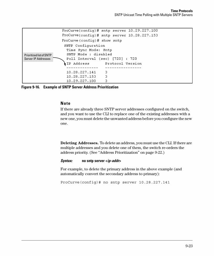
Time Protocols SNTP Unicast Time Polling with Multiple SNTP Servers
Prioritized list of SNTP Server IP Addresses
Figure 9-16. Example of SNTP Server Address Prioritization
Note If there are already three SNTP server addresses configured on the switch, and you want to use the CLI to replace one of the existing addresses with a new one, you must delete the unwanted address before you configure the new one.
Deleting Addresses. To delete an address, you must use the CLI. If there are multiple addresses and you delete one of them, the switch re-orders the address priority. (See “Address Prioritization” on page 9-22.)
Syntax: no sntp server <ip-addr>
For example, to delete the primary address in the above example (and automatically convert the secondary address to primary):
ProCurve(config)# no sntp server 10.28.227.141
9-23
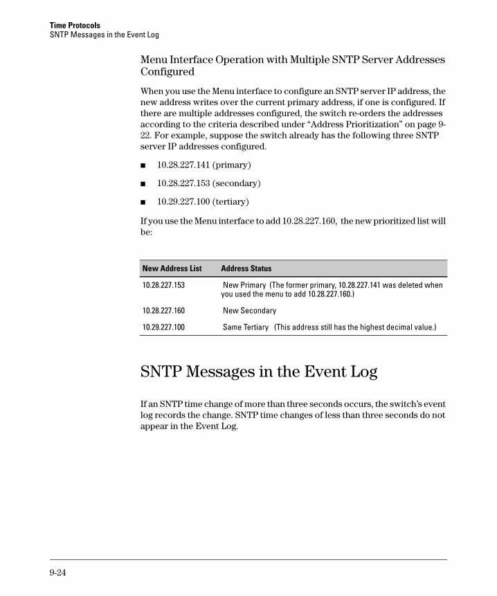
Time Protocols SNTP Messages in the Event Log
Menu Interface Operation with Multiple SNTP Server Addresses Configured
When you use the Menu interface to configure an SNTP server IP address, the new address writes over the current primary address, if one is configured. If there are multiple addresses configured, the switch re-orders the addresses according to the criteria described under “Address Prioritization” on page 922. For example, suppose the switch already has the following three SNTP server IP addresses configured.
■ 10.28.227.141 (primary)
■ 10.28.227.153 (secondary)
■ 10.29.227.100 (tertiary)
If you use the Menu interface to add 10.28.227.160, the new prioritized list will be:
New Address List Address Status
10.28.227.153 New Primary (The former primary, 10.28.227.141 was deleted when you used the menu to add 10.28.227.160.)
10.28.227.160 New Secondary
10.29.227.100 Same Tertiary (This address still has the highest decimal value.)
SNTP Messages in the Event Log
If an SNTP time change of more than three seconds occurs, the switch’s event log records the change. SNTP time changes of less than three seconds do not appear in the Event Log.
9-24
10
Port Status and Basic Configuration
Contents
Overview . . . . . . . . . . . . . . . . . . . . . . . . . . . . . . . . . . . . . . . . . . . . . . . . . . . . . 10-3
Viewing Port Status and Configuring Port Parameters . . . . . . . . . . . . . . . 10-3
Menu: Viewing Port Status and Configuring Port Parameters . . . . . 10-6
CLI: Viewing Port Status and Configuring Port Parameters . . . . . . . 10-7Using the CLI To View Port Status . . . . . . . . . . . . . . . . . . . . . . . . 10-8Displaying Spanning Tree Configuration Details . . . . . . . . . . . . 10-10Using the CLI To Configure Ports . . . . . . . . . . . . . . . . . . . . . . . . 10-10Using the CLI To Configure a Broadcast Limit . . . . . . . . . . . . . . 10-11Configuring HP Auto-MDIX . . . . . . . . . . . . . . . . . . . . . . . . . . . . . 10-13Manual Auto-MDIX Override on the Series 2600/2600-PWR and 2800 Switches . . . . . . . . . . . . . . . . . . . . . . . . . . . . . . . . . . . . . 10-14
Web: Viewing Port Status and Configuring Port Parameters . . . . . 10-17
Jumbo Packets on the Series 2800 Switches . . . . . . . . . . . . . . . . . . . . . . 10-17
Terminology . . . . . . . . . . . . . . . . . . . . . . . . . . . . . . . . . . . . . . . . . . . . . . 10-18
Operating Rules . . . . . . . . . . . . . . . . . . . . . . . . . . . . . . . . . . . . . . . . . . . 10-18
Configuring Jumbo Packet Operation . . . . . . . . . . . . . . . . . . . . . . . . 10-19Overview . . . . . . . . . . . . . . . . . . . . . . . . . . . . . . . . . . . . . . . . . . . . . 10-19Viewing the Current Jumbo Configuration . . . . . . . . . . . . . . . . . 10-20Enabling or Disabling Jumbo Traffic on a VLAN . . . . . . . . . . . . 10-22
Operating Notes for Jumbo Traffic-Handling . . . . . . . . . . . . . . . . . . 10-22
Troubleshooting . . . . . . . . . . . . . . . . . . . . . . . . . . . . . . . . . . . . . . . . . . 10-25
QoS Pass-Through Mode on the Series 2800 and 4100gl Switches . . . . 10-25General Operation . . . . . . . . . . . . . . . . . . . . . . . . . . . . . . . . . . . . . 10-25Priority Mapping With and Without QoS Pass-Through Mode . 10-26How to enable/disable QoS Pass-Through Mode . . . . . . . . . . . . 10-27
Configuring Port-Based Priority for Incoming Packets on the 4100gl and 6108 Switches . . . . . . . . . . . . . . . . . . . . . . . . . . . . . . . . . . . . . . 10-29
The Role of 802.1Q VLAN Tagging . . . . . . . . . . . . . . . . . . . . . . . . . . . 10-29
10-1
Port Status and Basic Configuration Contents
Outbound Port Queues and Packet Priority Settings . . . . . . . . . . . . 10-30
Operating Rules for Port-Based Priority . . . . . . . . . . . . . . . . . . . . . . 10-31
Configuring and Viewing Port-Based Priority . . . . . . . . . . . . . . . . . . 10-32
Messages Related to Prioritization . . . . . . . . . . . . . . . . . . . . . . . . . . . 10-33
Troubleshooting Prioritization . . . . . . . . . . . . . . . . . . . . . . . . . . . . . . 10-33
Using Friendly (Optional) Port Names . . . . . . . . . . . . . . . . . . . . . . . . . . . 10-34
Configuring and Operating Rules for Friendly Port Names . . . . . . . 10-34
Configuring Friendly Port Names . . . . . . . . . . . . . . . . . . . . . . . . . . . . 10-35
Displaying Friendly Port Names with Other Port Data . . . . . . . . . . 10-37
10-2
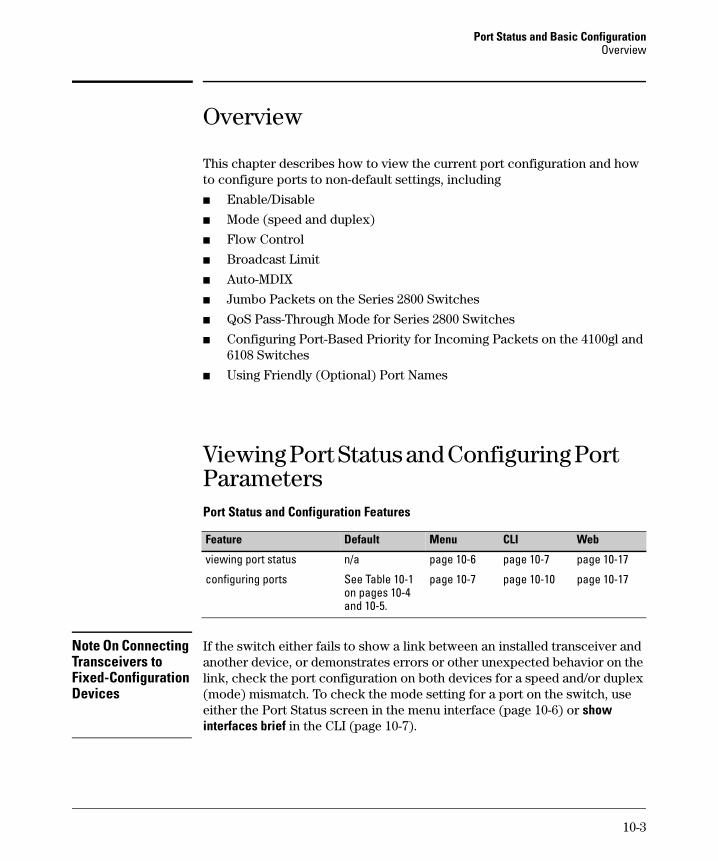
Port Status and Basic Configuration Overview
Overview
Note On Connecting Transceivers to Fixed-Configuration Devices
This chapter describes how to view the current port configuration and how to configure ports to non-default settings, including
■ Enable/Disable
■ Mode (speed and duplex)
■ Flow Control
■ Broadcast Limit
■ Auto-MDIX
■ Jumbo Packets on the Series 2800 Switches
■ QoS Pass-Through Mode for Series 2800 Switches
■ Configuring Port-Based Priority for Incoming Packets on the 4100gl and 6108 Switches
■ Using Friendly (Optional) Port Names
Viewing Port Status and Configuring Port Parameters Port Status and Configuration Features
Feature Default Menu CLI Web
viewing port status n/a page 10-6 page 10-7 page 10-17
configuring ports See Table 10-1 page 10-7 page 10-10 page 10-17 on pages 10-4 and 10-5.
If the switch either fails to show a link between an installed transceiver and another device, or demonstrates errors or other unexpected behavior on the link, check the port configuration on both devices for a speed and/or duplex (mode) mismatch. To check the mode setting for a port on the switch, use either the Port Status screen in the menu interface (page 10-6) or show interfaces brief in the CLI (page 10-7).
10-3
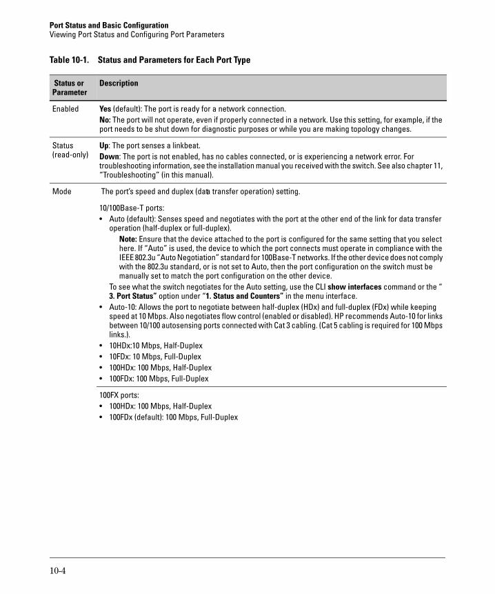
Port Status and Basic Configuration Viewing Port Status and Configuring Port Parameters
Table 10-1. Status and Parameters for Each Port Type
Parameter Status or Description
Enabled Yes (default): The port is ready for a network connection.No: The port will not operate, even if properly connected in a network. Use this setting, for example, if the port needs to be shut down for diagnostic purposes or while you are making topology changes.
Status Up: The port senses a linkbeat. (read-only) Down: The port is not enabled, has no cables connected, or is experiencing a network error. For
troubleshooting information, see the installation manual you received with the switch. See also chapter 11, “Troubleshooting” (in this manual).
Mode The port’s speed and duplex (data transfer operation) setting.
10/100Base-T ports: • Auto (default): Senses speed and negotiates with the port at the other end of the link for data transfer
operation (half-duplex or full-duplex). Note: Ensure that the device attached to the port is configured for the same setting that you select here. If “Auto” is used, the device to which the port connects must operate in compliance with the IEEE 802.3u “Auto Negotiation” standard for 100Base-T networks. If the other device does not comply with the 802.3u standard, or is not set to Auto, then the port configuration on the switch must be manually set to match the port configuration on the other device.
To see what the switch negotiates for the Auto setting, use the CLI show interfaces command or the “ 3. Port Status” option under “1. Status and Counters” in the menu interface.
• Auto-10: Allows the port to negotiate between half-duplex (HDx) and full-duplex (FDx) while keeping speed at 10 Mbps. Also negotiates flow control (enabled or disabled). HP recommends Auto-10 for links between 10/100 autosensing ports connected with Cat 3 cabling. (Cat 5 cabling is required for 100 Mbps links.).
• 10HDx:10 Mbps, Half-Duplex • 10FDx: 10 Mbps, Full-Duplex • 100HDx: 100 Mbps, Half-Duplex • 100FDx: 100 Mbps, Full-Duplex
100FX ports: • 100HDx: 100 Mbps, Half-Duplex • 100FDx (default): 100 Mbps, Full-Duplex
10-4
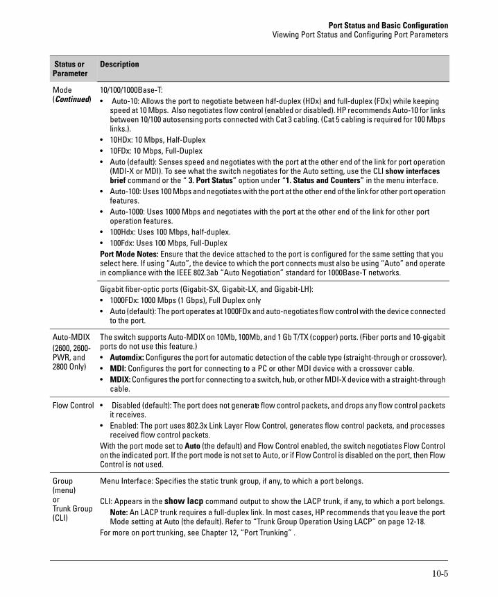
Port Status and Basic Configuration Viewing Port Status and Configuring Port Parameters
Parameter Status or Description
Mode 10/100/1000Base-T: (Continued) • Auto-10: Allows the port to negotiate between half-duplex (HDx) and full-duplex (FDx) while keeping
speed at 10 Mbps. Also negotiates flow control (enabled or disabled). HP recommends Auto-10 for links between 10/100 autosensing ports connected with Cat 3 cabling. (Cat 5 cabling is required for 100 Mbps links.).
• 10HDx: 10 Mbps, Half-Duplex • 10FDx: 10 Mbps, Full-Duplex • Auto (default): Senses speed and negotiates with the port at the other end of the link for port operation
(MDI-X or MDI). To see what the switch negotiates for the Auto setting, use the CLI show interfaces brief command or the “ 3. Port Status” option under “1. Status and Counters” in the menu interface.
• Auto-100: Uses 100 Mbps and negotiates with the port at the other end of the link for other port operation features.
• Auto-1000: Uses 1000 Mbps and negotiates with the port at the other end of the link for other port operation features.
• 100Hdx: Uses 100 Mbps, half-duplex. • 100Fdx: Uses 100 Mbps, Full-Duplex Port Mode Notes: Ensure that the device attached to the port is configured for the same setting that you select here. If using “Auto”, the device to which the port connects must also be using “Auto” and operate in compliance with the IEEE 802.3ab “Auto Negotiation” standard for 1000Base-T networks.
Gigabit fiber-optic ports (Gigabit-SX, Gigabit-LX, and Gigabit-LH): • 1000FDx: 1000 Mbps (1 Gbps), Full Duplex only • Auto (default): The port operates at 1000FDx and auto-negotiates flow control with the device connected
to the port.
Auto-MDIX The switch supports Auto-MDIX on 10Mb, 100Mb, and 1 Gb T/TX (copper) ports. (Fiber ports and 10-gigabit (2600, 2600- ports do not use this feature.)PWR, and • Automdix: Configures the port for automatic detection of the cable type (straight-through or crossover).2800 Only) • MDI: Configures the port for connecting to a PC or other MDI device with a crossover cable.
• MDIX: Configures the port for connecting to a switch, hub, or other MDI-X device with a straight-through cable.
Flow Control • Disabled (default): The port does not generate flow control packets, and drops any flow control packets it receives.
• Enabled: The port uses 802.3x Link Layer Flow Control, generates flow control packets, and processes received flow control packets.
With the port mode set to Auto (the default) and Flow Control enabled, the switch negotiates Flow Control on the indicated port. If the port mode is not set to Auto, or if Flow Control is disabled on the port, then Flow Control is not used.
Group Menu Interface: Specifies the static trunk group, if any, to which a port belongs.(menu) or CLI: Appears in the show lacp command output to show the LACP trunk, if any, to which a port belongs.Trunk Group Note: An LACP trunk requires a full-duplex link. In most cases, HP recommends that you leave the port (CLI) Mode setting at Auto (the default). Refer to “Trunk Group Operation Using LACP” on page 12-18.
For more on port trunking, see Chapter 12, “Port Trunking” .
10-5
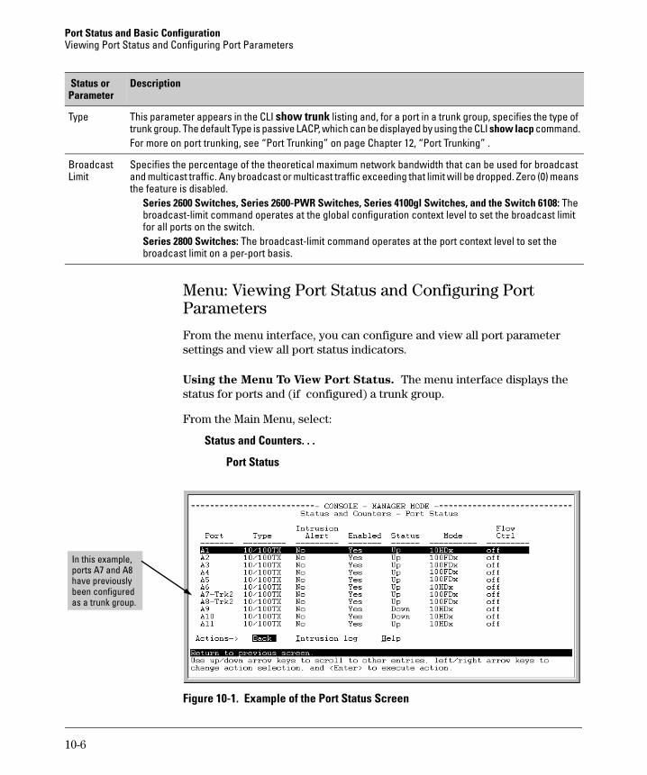
Port Status and Basic Configuration Viewing Port Status and Configuring Port Parameters
Parameter Status or Description
Type This parameter appears in the CLI show trunk listing and, for a port in a trunk group, specifies the type of trunk group. The default Type is passive LACP, which can be displayed by using the CLI show lacp command. For more on port trunking, see “Port Trunking” on page Chapter 12, “Port Trunking” .
Broadcast Specifies the percentage of the theoretical maximum network bandwidth that can be used for broadcast Limit and multicast traffic. Any broadcast or multicast traffic exceeding that limit will be dropped. Zero (0) means
the feature is disabled. Series 2600 Switches, Series 2600-PWR Switches, Series 4100gl Switches, and the Switch 6108: The broadcast-limit command operates at the global configuration context level to set the broadcast limit for all ports on the switch. Series 2800 Switches: The broadcast-limit command operates at the port context level to set the broadcast limit on a per-port basis.
Menu: Viewing Port Status and Configuring Port Parameters
From the menu interface, you can configure and view all port parameter settings and view all port status indicators.
Using the Menu To View Port Status. The menu interface displays the status for ports and (if configured) a trunk group.
From the Main Menu, select:
Status and Counters. . .
Port Status
In this example, ports A7 and A8 have previously been configured as a trunk group.
Figure 10-1. Example of the Port Status Screen
10-6
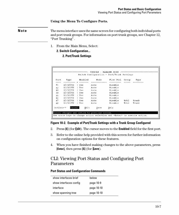
Port Status and Basic Configuration Viewing Port Status and Configuring Port Parameters
Using the Menu To Configure Ports.
N o t e The menu interface uses the same screen for configuring both individual ports and port trunk groups. For information on port trunk groups, see Chapter 12, “Port Trunking” .
1. From the Main Menu, Select:
2. Switch Configuration... 2. Port/Trunk Settings
Figure 10-2. Example of Port/Trunk Settings with a Trunk Group Configured
2. Press [E] (for Edit). The cursor moves to the Enabled field for the first port.
3. Refer to the online help provided with this screen for further information on configuration options for these features.
4. When you have finished making changes to the above parameters, press [Enter], then press [S] (for Save).
CLI: Viewing Port Status and Configuring Port Parameters
Port Status and Configuration Commands
show interfaces brief below
show interfaces config page 10-9
interface page 10-10
show spanning tree page 10-10
10-7
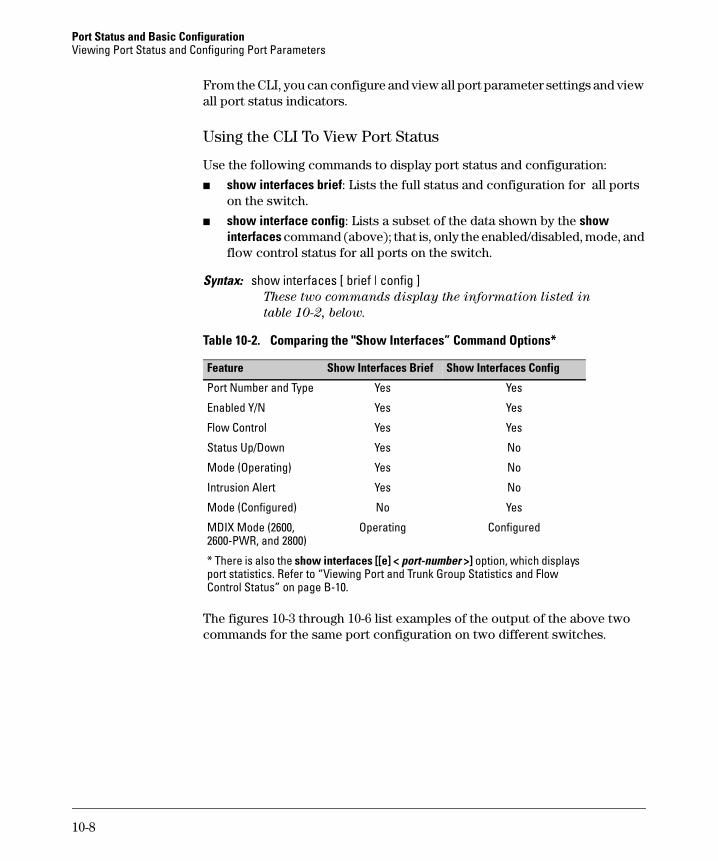
Port Status and Basic Configuration Viewing Port Status and Configuring Port Parameters
From the CLI, you can configure and view all port parameter settings and view all port status indicators.
Using the CLI To View Port Status
Use the following commands to display port status and configuration:
■ show interfaces brief: Lists the full status and configuration for all ports on the switch.
■ show interface config: Lists a subset of the data shown by the show interfaces command (above); that is, only the enabled/disabled, mode, and flow control status for all ports on the switch.
Syntax: show interfaces [ brief | config ] These two commands display the information listed in
table 10-2, below.
Table 10-2. Comparing the "Show Interfaces” Command Options*
Feature Show Interfaces ConfigShow Interfaces Brief
Port Number and Type Yes Yes
Enabled Y/N Yes Yes
Flow Control Yes Yes
Status Up/Down Yes No
Mode (Operating) Yes No
Intrusion Alert Yes No
Mode (Configured) No Yes
MDIX Mode (2600, Operating Configured 2600-PWR, and 2800)
* There is also the show interfaces [[e] < port-number >] option, which displays port statistics. Refer to “Viewing Port and Trunk Group Statistics and Flow Control Status” on page B-10.
The figures 10-3 through 10-6 list examples of the output of the above two commands for the same port configuration on two different switches.
10-8
Port Status and Basic Configuration Viewing Port Status and Configuring Port Parameters
Current Operating Mode
Figure 10-3. Example Show Interface Command Listing, 4100gl Switch
Current Configured Mode
Figure 10-4. Example Show Interface Config Command Listing, 4100gl Switch
ProCurve(config)# show interface brief
Status and Counters - Port Status
| Intrusion MDI Flow Port Type | Alert Enabled Status Mode Mode Ctrl ------- --------- + --------- ------- ------ ---------- ----- -----1 10/100TX | No Yes Up 100FDx MDI off 2 10/100TX | No Yes Down 100FDx MDI off 3 10/100TX | No Yes Down 100FDx MDI off 4 10/100TX | No Yes Down 100FDx MDI off 5 10/100TX | No Yes Down 100FDx MDI off 6 10/100TX | No Yes Down 100FDx MDI off 7 10/100TX | No Yes Down 100FDx MDIX off 8 10/100TX | No Yes Down 100FDx MDI off 9 10/100TX | No Yes Up 100FDx MDI off 10 10/100TX | No Yes Down 100FDx MDI off
Current Operating Mode
Figure 10-5. Example Show Interface Brief Command Listing, 2600 Switch
10-9
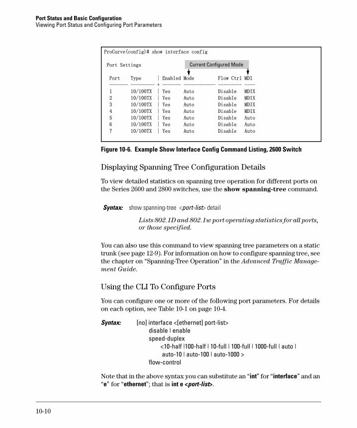
Port Status and Basic Configuration Viewing Port Status and Configuring Port Parameters
ProCurve(config)# show interface config
Port Settings Current Configured Mode
Port Type | Enabled Mode Flow Ctrl MDI
------- --------- + ------- ------------ --------- ----
1 10/100TX | Yes Auto Disable MDIX
2 10/100TX | Yes Auto Disable MDIX
3 10/100TX | Yes Auto Disable MDIX
4 10/100TX | Yes Auto Disable MDIX
5 10/100TX | Yes Auto Disable Auto
6 10/100TX | Yes Auto Disable Auto
7 10/100TX | Yes Auto Disable Auto
Figure 10-6. Example Show Interface Config Command Listing, 2600 Switch
Displaying Spanning Tree Configuration Details
To view detailed statistics on spanning tree operation for different ports on the Series 2600 and 2800 switches, use the show spanning-tree command.
Syntax: show spanning-tree <port-list> detail
Lists 802.1D and 802.1w port operating statistics for all ports,
or those specified.
You can also use this command to view spanning tree parameters on a static trunk (see page 12-9). For information on how to configure spanning tree, see the chapter on “Spanning-Tree Operation” in the Advanced Traffic Manage
ment Guide.
Using the CLI To Configure Ports
You can configure one or more of the following port parameters. For details on each option, see Table 10-1 on page 10-4.
Syntax: [no] interface <[ethernet] port-list> disable | enable speed-duplex
<10-half |100-half | 10-full | 100-full | 1000-full | auto | auto-10 | auto-100 | auto-1000 >
flow-control
Note that in the above syntax you can substitute an “int” for “interface” and an “e” for “ethernet”; that is int e <port-list>.
10-10
Port Status and Basic Configuration Viewing Port Status and Configuring Port Parameters
For example, to configure ports C1 through C3 and port C6 for 100 Mbps full-duplex, you would enter these commands:
ProCurve(config)# int e c1-c3,c6 speed-duplex 100-full
Similarly, to configure a single port with the settings in the above command, you could either enter the same command with only the one port identified, or go to the context level for that port and then enter the command. For example, to enter the context level for port C6 and then configure that port for 100FDx:
ProCurve(config)# int e c6ProCurve(eth-C6)# speed-duplex 100-full
If port C8 was disabled, and you wanted to enable it and configure it for 100FDx with flow-control active, you could do so with either of the following command sets.
■ These commands enable and configure port C8 from the config level: ProCurve(config)# int e c8 enable ProCurve(config)# int e c8 speed-duplex 100-fullProCurve(config)# int e c8 flow-control
■ These commands select the context level for port C8 and then apply all of the configuration commands to port C8: ProCurve(config)# int e c8ProCurve(eth-C8)# enable ProCurve(eth-C8)# speed-duplex 100-full ProCurve(eth-C8)# flow-control
Using the CLI To Configure a Broadcast Limit
The Series 2800 Switches use per-port broadcast-limit settings. The Switch 6108, Series 2600, Series 2600-PWR, and Series 4100GL Switches use a single broadcast-limit setting for all ports on the switch.
Broadcast Limit on the Switch 6108, Series 2600, Series 2600-PWR,
and Series 4100gl Switches. This command operates at the global configuration level to configure one global instance of the broadcast limit for all ports on the switch. To implement the command you must also execute write-memory and reboot the switch.
N o t e You must execute write memory and reboot the switch to implement the new broadcast-limit setting. Even though the broadcast-limit setting appears in the show running output and (after write memory) in the startup-config output, the switch does not implement the new setting until rebooted.
10-11
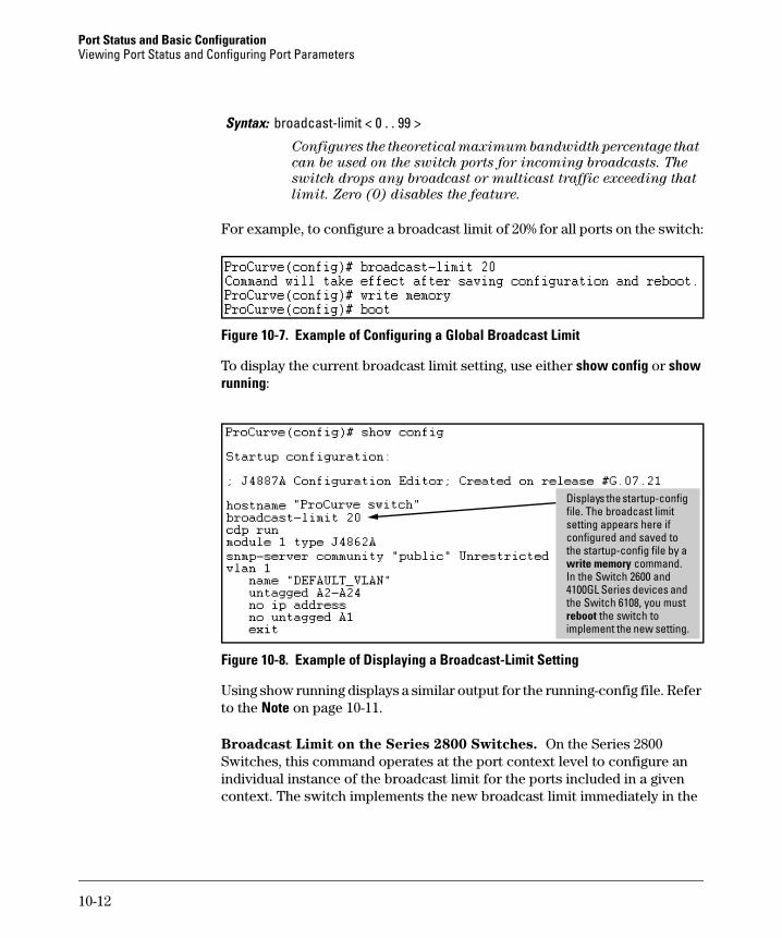
Port Status and Basic Configuration Viewing Port Status and Configuring Port Parameters
Syntax: broadcast-limit < 0 . . 99 >
Configures the theoretical maximum bandwidth percentage that
can be used on the switch ports for incoming broadcasts. The
switch drops any broadcast or multicast traffic exceeding that
limit. Zero (0) disables the feature.
For example, to configure a broadcast limit of 20% for all ports on the switch:
Figure 10-7. Example of Configuring a Global Broadcast Limit
To display the current broadcast limit setting, use either show config or show running:
Di
In the Switch 2600 and
splays the startup-config file. The broadcast limit setting appears here if configured and saved to the startup-config file by a write memory command.
4100GL Series devices and the Switch 6108, you must reboot the switch to implement the new setting.
Figure 10-8. Example of Displaying a Broadcast-Limit Setting
Using show running displays a similar output for the running-config file. Refer to the Note on page 10-11.
Broadcast Limit on the Series 2800 Switches. On the Series 2800 Switches, this command operates at the port context level to configure an individual instance of the broadcast limit for the ports included in a given context. The switch implements the new broadcast limit immediately in the
10-12
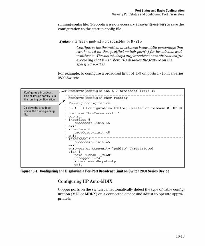
Port Status and Basic Configuration Viewing Port Status and Configuring Port Parameters
running-config file. (Rebooting is not necessary.) Use write-memory to save the configuration to the startup-config file.
Syntax: interface < port-list > broadcast-limit < 0 - 99 >
Configures the theoretical maximum bandwidth percentage that
can be used on the specified switch port(s) for broadcasts and
multicasts. The switch drops any broadcast or multicast traffic
exceeding that limit. Zero (0) disables the feature on the
specified port(s).
For example, to configure a broadcast limit of 45% on ports 1 - 10 in a Series 2800 Switch:
i
ifile.
Conf gures a broadcast limit of 45% on ports 5 - 7 in the running configuration.
Displays the broadcast-limit in the runn ng-config
Figure 10-1. Configuring and Displaying a Per-Port Broadcast Limit on Switch 2800 Series Device
Configuring HP Auto-MDIX
Copper ports on the switch can automatically detect the type of cable configuration (MDI or MDI-X) on a connected device and adjust to operate appropriately.
10-13
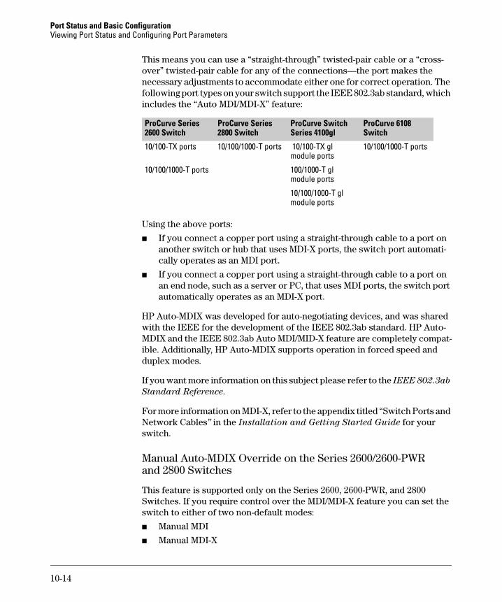
Port Status and Basic Configuration Viewing Port Status and Configuring Port Parameters
This means you can use a “straight-through” twisted-pair cable or a “crossover” twisted-pair cable for any of the connections—the port makes the necessary adjustments to accommodate either one for correct operation. The following port types on your switch support the IEEE 802.3ab standard, which includes the “Auto MDI/MDI-X” feature:
ProCurve Series ProCurve Series ProCurve Switch ProCurve 6108 2600 Switch 2800 Switch Series 4100gl Switch
10/100-TX ports 10/100/1000-T ports 10/100-TX gl 10/100/1000-T portsmodule ports
10/100/1000-T ports 100/1000-T gl module ports
10/100/1000-T gl module ports
Using the above ports:
■ If you connect a copper port using a straight-through cable to a port on another switch or hub that uses MDI-X ports, the switch port automatically operates as an MDI port.
■ If you connect a copper port using a straight-through cable to a port on an end node, such as a server or PC, that uses MDI ports, the switch port automatically operates as an MDI-X port.
HP Auto-MDIX was developed for auto-negotiating devices, and was shared with the IEEE for the development of the IEEE 802.3ab standard. HP Auto-MDIX and the IEEE 802.3ab Auto MDI/MID-X feature are completely compatible. Additionally, HP Auto-MDIX supports operation in forced speed and duplex modes.
If you want more information on this subject please refer to the IEEE 802.3ab
Standard Reference.
For more information on MDI-X, refer to the appendix titled “Switch Ports and Network Cables” in the Installation and Getting Started Guide for your switch.
Manual Auto-MDIX Override on the Series 2600/2600-PWR and 2800 Switches
This feature is supported only on the Series 2600, 2600-PWR, and 2800 Switches. If you require control over the MDI/MDI-X feature you can set the switch to either of two non-default modes:
■ Manual MDI
■ Manual MDI-X
10-14
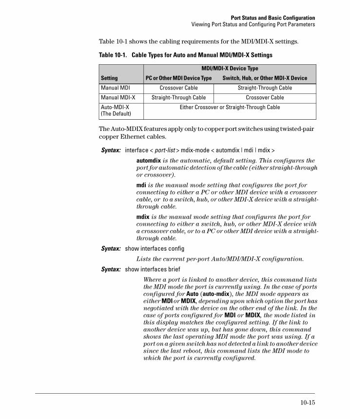
Port Status and Basic Configuration Viewing Port Status and Configuring Port Parameters
Table 10-1 shows the cabling requirements for the MDI/MDI-X settings.
Table 10-1. Cable Types for Auto and Manual MDI/MDI-X Settings
MDI/MDI-X Device Type
Setting PC or Other MDI Device Type Switch, Hub, or Other MDI-X Device
Manual MDI Crossover Cable Straight-Through Cable
Manual MDI-X Straight-Through Cable Crossover Cable
Auto-MDI-X (The Default)
Either Crossover or Straight-Through Cable
The Auto-MDIX features apply only to copper port switches using twisted-pair copper Ethernet cables.
Syntax: interface < port-list > mdix-mode < automdix | mdi | mdix >
automdix is the automatic, default setting. This configures the
port for automatic detection of the cable (either straight-through
or crossover).
mdi is the manual mode setting that configures the port for
connecting to either a PC or other MDI device with a crossover
cable, or to a switch, hub, or other MDI-X device with a straight-
through cable.
mdix is the manual mode setting that configures the port for
connecting to either a switch, hub, or other MDI-X device with
a crossover cable, or to a PC or other MDI device with a straight-
through cable.
Syntax: show interfaces config
Lists the current per-port Auto/MDI/MDI-X configuration.
Syntax: show interfaces brief
Where a port is linked to another device, this command lists
the MDI mode the port is currently using. In the case of ports
configured for Auto (auto-mdix), the MDI mode appears as
either MDI or MDIX, depending upon which option the port has
negotiated with the device on the other end of the link. In the
case of ports configured for MDI or MDIX, the mode listed in
this display matches the configured setting. If the link to
another device was up, but has gone down, this command
shows the last operating MDI mode the port was using. If a
port on a given switch has not detected a link to another device
since the last reboot, this command lists the MDI mode to
which the port is currently configured.
10-15
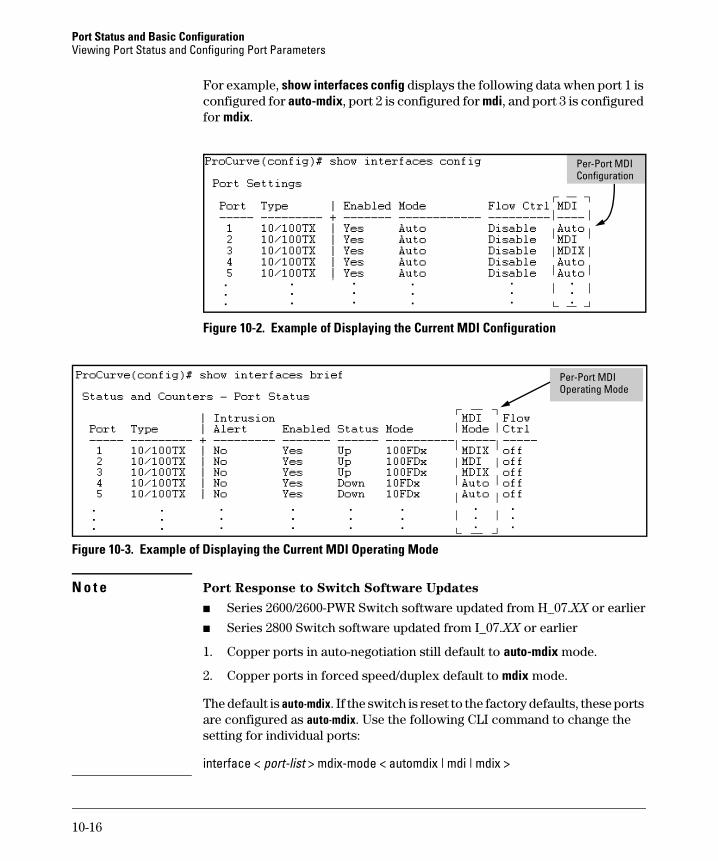
Port Status and Basic Configuration Viewing Port Status and Configuring Port Parameters
For example, show interfaces config displays the following data when port 1 is configured for auto-mdix, port 2 is configured for mdi, and port 3 is configured for mdix.
Per-Port MDI Configuration
Figure 10-2. Example of Displaying the Current MDI Configuration
Per-Port MDI Operating Mode
Figure 10-3. Example of Displaying the Current MDI Operating Mode
N o t e Port Response to Switch Software Updates
■ Series 2600/2600-PWR Switch software updated from H_07.XX or earlier
■ Series 2800 Switch software updated from I_07.XX or earlier
1. Copper ports in auto-negotiation still default to auto-mdix mode.
2. Copper ports in forced speed/duplex default to mdix mode.
The default is auto-mdix. If the switch is reset to the factory defaults, these ports are configured as auto-mdix. Use the following CLI command to change the setting for individual ports:
interface < port-list > mdix-mode < automdix | mdi | mdix >
10-16
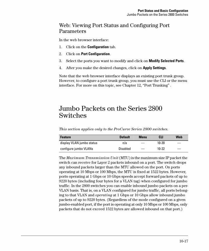
Port Status and Basic Configuration Jumbo Packets on the Series 2800 Switches
Web: Viewing Port Status and Configuring Port Parameters
In the web browser interface:
1. Click on the Configuration tab.
2. Click on Port Configuration.
3. Select the ports you want to modify and click on Modify Selected Ports.
4. After you make the desired changes, click on Apply Settings.
Note that the web browser interface displays an existing port trunk group. However, to configure a port trunk group, you must use the CLI or the menu interface. For more on this topic, see Chapter 12, “Port Trunking” .
Jumbo Packets on the Series 2800 Switches
This section applies only to the ProCurve Series 2800 switches.
Default Menu
n/a — 10-20 —
Feature CLI Web
display VLAN jumbo status
configure jumbo VLANs Disabled — 10-22 —
The Maximum Transmission Unit (MTU) is the maximum size IP packet the switch can receive for Layer 2 packets inbound on a port. The switch drops any inbound packets larger than the MTU allowed on the port. On ports operating at 10 Mbps or 100 Mbps, the MTU is fixed at 1522 bytes. However, ports operating at 1 Gbps or 10 Gbps speeds accept forward packets of up to 9220 bytes (including four bytes for a VLAN tag) when configured for jumbo traffic. In the 2800 switches you can enable inbound jumbo packets on a per-VLAN basis. That is, on a VLAN configured for jumbo traffic, all ports belonging to that VLAN and operating at 1 Gbps or 10 Gbps allow inbound jumbo packets of up to 9220 bytes. (Regardless of the mode configured on a given jumbo-enabled port, if the port is operating at only 10 Mbps or 100 Mbps, only packets that do not exceed 1522 bytes are allowed inbound on that port.)
10-17
Port Status and Basic Configuration Jumbo Packets on the Series 2800 Switches
Terminology
Jumbo Packet: On the Series 2800 switches, an IP packet exceeding 1522 bytes in size. The maximum Jumbo packet size is 9220 bytes. (This size includes 4 bytes for the VLAN tag.)
Jumbo VLAN: A VLAN configured to allow inbound jumbo traffic. All ports belonging to a jumbo and operating at 1 Gbps or higher can receive jumbo packets from external devices.
MTU (Maximum Transmission Unit): This is the maximum-size IP packet the switch can receive for Layer 2 packets inbound on a port. The switch allows jumbo packets of up to 9220 bytes.
Standard MTU: On the Series 2800 switches, an IP packet of 1522 bytes in size. (This size includes 4 bytes for the VLAN tag.)
Operating Rules
■ Required Port Speed: The Series 2800 switches allow inbound and outbound jumbo packets on ports operating at speeds of 1 gigabit or higher. At lower port speeds, only standard (1522-byte or smaller) packets are allowed, regardless of the jumbo configuration.
■ Flow Control: Disable flow control (the default setting) on any ports or trunks through which you want to transmit or receive jumbo packets. Leaving flow control enabled on a port can cause a high rate of jumbo drops to occur on the port.
■ GVRP Operation: A VLAN enabled for jumbo traffic cannot be used to create a dynamic VLAN. A port belonging to a statically configured, jumbo-enabled VLAN cannot join a dynamic VLAN.
■ Port Adds and Moves: If you add a port to a VLAN that is already configured for jumbo traffic, the switch enables that port to receive jumbo traffic. If you remove a port from a jumbo-enabled VLAN, the switch disables jumbo traffic capability on the port only if the port is not currently a member of another jumbo-enabled VLAN. This same operation applies to port trunks.
■ Jumbo Traffic Sources: A port belonging to a jumbo-enabled VLAN can receive inbound jumbo packets through any VLAN to which it belongs, including non-jumbo VLANs. For example, if VLAN 10 (without jumbos enabled) and VLAN 20 (with jumbos enabled) are both configured on a switch, and port 1 belongs to both VLANs, then port 1 can receive jumbo
10-18
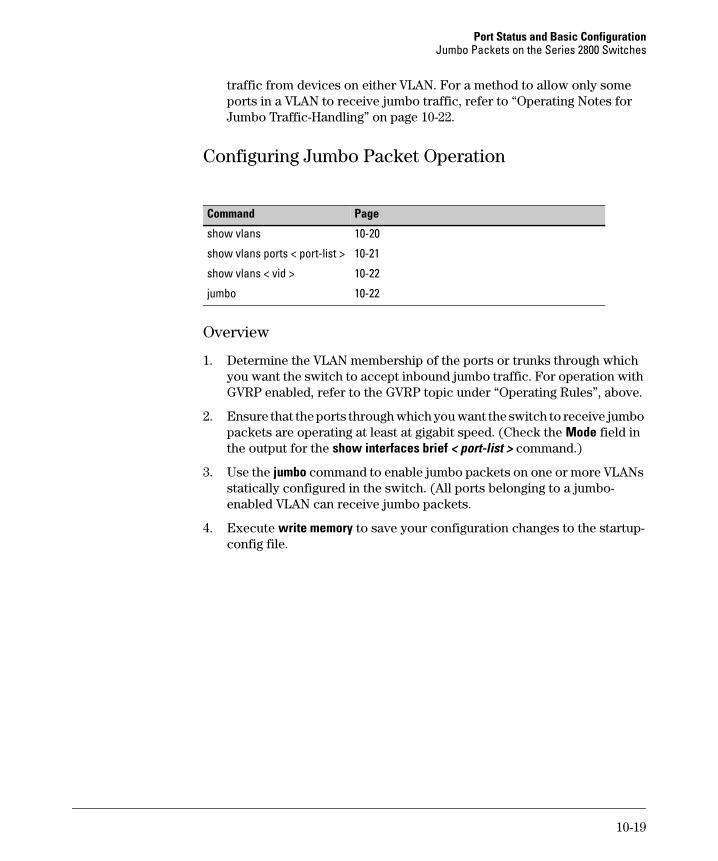
Port Status and Basic Configuration Jumbo Packets on the Series 2800 Switches
traffic from devices on either VLAN. For a method to allow only some ports in a VLAN to receive jumbo traffic, refer to “Operating Notes for Jumbo Traffic-Handling” on page 10-22.
Configuring Jumbo Packet Operation
Command Page
show vlans 10-20
show vlans ports < port-list > 10-21
show vlans < vid > 10-22
jumbo 10-22
Overview
1. Determine the VLAN membership of the ports or trunks through which you want the switch to accept inbound jumbo traffic. For operation with GVRP enabled, refer to the GVRP topic under “Operating Rules”, above.
2. Ensure that the ports through which you want the switch to receive jumbo packets are operating at least at gigabit speed. (Check the Mode field in the output for the show interfaces brief < port-list > command.)
3. Use the jumbo command to enable jumbo packets on one or more VLANs statically configured in the switch. (All ports belonging to a jumbo-enabled VLAN can receive jumbo packets.
4. Execute write memory to save your configuration changes to the startupconfig file.
10-19
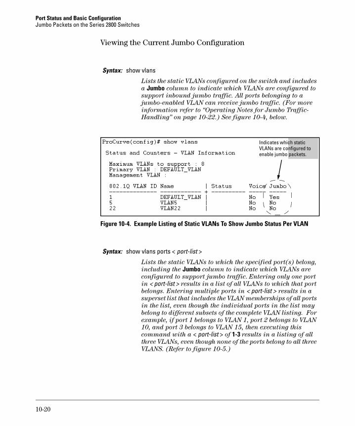
Port Status and Basic Configuration Jumbo Packets on the Series 2800 Switches
Viewing the Current Jumbo Configuration
Syntax: show vlans
Lists the static VLANs configured on the switch and includes
a Jumbo column to indicate which VLANs are configured to
support inbound jumbo traffic. All ports belonging to a
jumbo-enabled VLAN can receive jumbo traffic. (For more
information refer to “Operating Notes for Jumbo Traffic-
Handling” on page 10-22.) See figure 10-4, below.
iIndicates wh ch static VLANs are configured to enable jumbo packets.
Figure 10-4. Example Listing of Static VLANs To Show Jumbo Status Per VLAN
Syntax: show vlans ports < port-list >
Lists the static VLANs to which the specified port(s) belong,
including the Jumbo column to indicate which VLANs are
configured to support jumbo traffic. Entering only one port
in < port-list > results in a list of all VLANs to which that port
belongs. Entering multiple ports in < port-list > results in a
superset list that includes the VLAN memberships of all ports
in the list, even though the individual ports in the list may
belong to different subsets of the complete VLAN listing. For
example, if port 1 belongs to VLAN 1, port 2 belongs to VLAN
10, and port 3 belongs to VLAN 15, then executing this
command with a < port-list > of 1-3 results in a listing of all
three VLANs, even though none of the ports belong to all three
VLANS. (Refer to figure 10-5.)
10-20
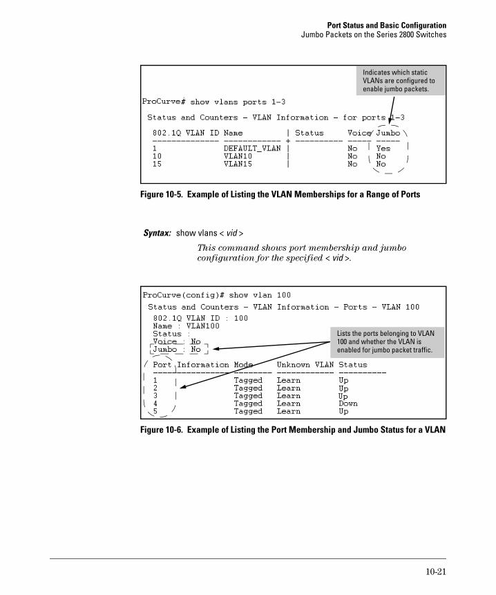
Port Status and Basic Configuration Jumbo Packets on the Series 2800 Switches
j
Indicates which static VLANs are configured to enable umbo packets.
Figure 10-5. Example of Listing the VLAN Memberships for a Range of Ports
Syntax: show vlans < vid >
This command shows port membership and jumbo
configuration for the specified < vid >.
Lists the ports belonging to VLAN 100 and whether the VLAN is enabled for jumbo packet traffic.
Figure 10-6. Example of Listing the Port Membership and Jumbo Status for a VLAN
10-21
Port Status and Basic Configuration Jumbo Packets on the Series 2800 Switches
Enabling or Disabling Jumbo Traffic on a VLAN
Syntax: vlan < vid > jumbo[ no ] vlan < vid > jumbo
Configures the specified VLAN to allow jumbo packets on all
ports on the switch that belong to that VLAN. If the VLAN is
not already configured on the switch, vlan < vid > jumbo also
creates the VLAN. Note that a port belonging to one jumbo
VLAN can receive jumbo packets through any other VLAN
statically configured on the switch, regardless of whether the
other VLAN is enabled for jumbo packets. The [no] form of the
command disables inbound jumbo traffic on all ports in the
specified VLAN that do not also belong to another VLAN that
is enabled for jumbo traffic. In a VLAN context, the command
forms are jumbo and no jumbo. (Default: Jumbos disabled on
the specified VLAN.)
Operating Notes for Jumbo Traffic-Handling
■ ProCurve does not recommend configuring a voice VLAN to accept jumbo packets. Voice VLAN packets are typically small, and allowing a voice VLAN to accept jumbo packet traffic can degrade the voice transmission performance.
■ You can configure the default, primary, and/or (if configured) the management VLAN to accept jumbo packets on all ports belonging to the VLAN.
■ When the switch applies the default MTU (1522-bytes) to a VLAN, all ports in the VLAN can receive incoming packets of up to 1522 bytes in length. When the switch applies the jumbo MTU (9220 bytes) to a VLAN, all ports in that VLAN can receive incoming packets of up to 9220 bytes in length. A port receiving packets exceeding the applicable MTU drops such packets, causing the switch to generate an Event Log message and increment the “Giant Rx” counter (displayed by show interfaces < port-list >).
■ The switch does not allow flow control and jumbo packet capability to co-exist on a port. Attempting to configure both on the same port generates an error message in the CLI and sends a similar message to the Event Log.
■ The default MTU on the Series 2800 switches is 1522 bytes (including 4 bytes for the VLAN tag). The jumbo MTU is 9220 bytes (including 4 bytes for the VLAN tag).
10-22
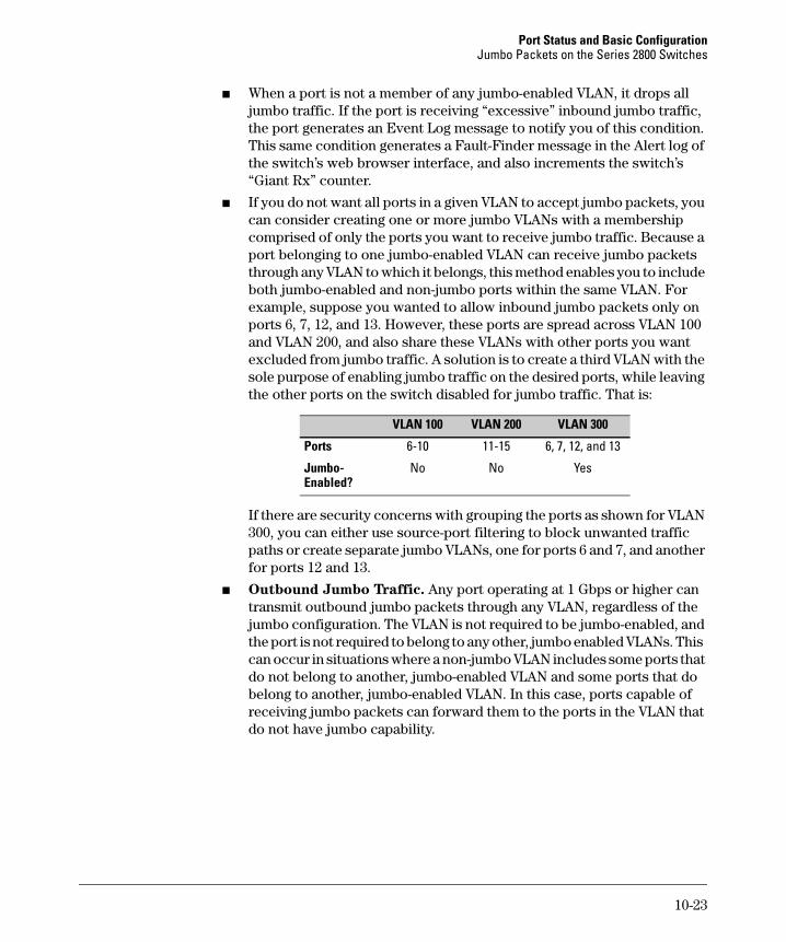
Port Status and Basic Configuration Jumbo Packets on the Series 2800 Switches
■ When a port is not a member of any jumbo-enabled VLAN, it drops all jumbo traffic. If the port is receiving “excessive” inbound jumbo traffic, the port generates an Event Log message to notify you of this condition. This same condition generates a Fault-Finder message in the Alert log of the switch’s web browser interface, and also increments the switch’s “Giant Rx” counter.
■ If you do not want all ports in a given VLAN to accept jumbo packets, you can consider creating one or more jumbo VLANs with a membership comprised of only the ports you want to receive jumbo traffic. Because a port belonging to one jumbo-enabled VLAN can receive jumbo packets through any VLAN to which it belongs, this method enables you to include both jumbo-enabled and non-jumbo ports within the same VLAN. For example, suppose you wanted to allow inbound jumbo packets only on ports 6, 7, 12, and 13. However, these ports are spread across VLAN 100 and VLAN 200, and also share these VLANs with other ports you want excluded from jumbo traffic. A solution is to create a third VLAN with the sole purpose of enabling jumbo traffic on the desired ports, while leaving the other ports on the switch disabled for jumbo traffic. That is:
6-10 11-15
VLAN 100 VLAN 200 VLAN 300
Ports 6, 7, 12, and 13
Jumbo- No No Yes Enabled?
If there are security concerns with grouping the ports as shown for VLAN 300, you can either use source-port filtering to block unwanted traffic paths or create separate jumbo VLANs, one for ports 6 and 7, and another for ports 12 and 13.
■ Outbound Jumbo Traffic. Any port operating at 1 Gbps or higher can transmit outbound jumbo packets through any VLAN, regardless of the jumbo configuration. The VLAN is not required to be jumbo-enabled, and the port is not required to belong to any other, jumbo enabled VLANs. This can occur in situations where a non-jumbo VLAN includes some ports that do not belong to another, jumbo-enabled VLAN and some ports that do belong to another, jumbo-enabled VLAN. In this case, ports capable of receiving jumbo packets can forward them to the ports in the VLAN that do not have jumbo capability.
10-23
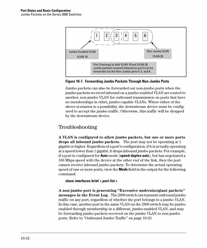
Port Status and Basic Configuration Jumbo Packets on the Series 2800 Switches
1 52 3 4 6
Jumbo-Enabled VLAN
VLAN 10
Non-Jumbo VLAN
VLAN 20
Port 3 belongs to both VLAN 10 and VLAN 20. Jumbo packets received inbound on port 3 can be forwarded out the Non-Jumbo ports 4, 5, and 6.
Figure 10-7. Forwarding Jumbo Packets Through Non-Jumbo Ports
Jumbo packets can also be forwarded out non-jumbo ports when the jumbo packets received inbound on a jumbo-enabled VLAN are routed to another, non-jumbo VLAN for outbound transmission on ports that have no memberships in other, jumbo-capable VLANs. Where either of the above scenarios is a possibility, the downstream device must be configured to accept the jumbo traffic. Otherwise, this traffic will be dropped by the downstream device.
Troubleshooting
A VLAN is configured to allow jumbo packets, but one or more ports
drops all inbound jumbo packets. The port may not be operating at 1 gigabit or higher. Regardless of a port’s configuration, if it is actually operating at a speed lower than 1 gigabit, it drops inbound jumbo packets. For example, if a port is configured for Auto mode (speed-duplex auto), but has negotiated a 100 Mbps speed with the device at the other end of the link, then the port cannot receive inbound jumbo packets. To determine the actual operating speed of one or more ports, view the Mode field in the output for the following command:
show interfaces brief < port-list >
A non-jumbo port is generating “Excessive undersize/giant packets”
messages in the Event Log. The 2800 switch can transmit outbound jumbo traffic on any port, regardless of whether the port belongs to a jumbo VLAN. In this case, another port in the same VLAN on the 2800 switch may be jumbo-enabled through membership in a different, jumbo-enabled VLAN, and may be forwarding jumbo packets received on the jumbo VLAN to non-jumbo ports. Refer to “Outbound Jumbo Traffic” on page 10-23.
10-24

Port Status and Basic Configuration QoS Pass-Through Mode on the Series 2800 and 4100gl Switches
QoS Pass-Through Mode on the Series 2800 and 4100gl Switches
QoS Pass-Through mode is designed to enhance the performance of line-rate traffic transfers through the Series 2800 and 4100gl switches. This feature should only be used in environments where Quality of Service (QoS) is not of major importance, but where lossless data transfers are key. This command disables any discrimination of QoS queues for traffic, consolidating packet buffer memory to provide line-rate flows with no loss of data.
General Operation
The port buffering design for the switch has been optimized for gigabit-to-gigabit traffic flows. For this reason, some flows from Gigabit-to-100Base or even 100Base-to-10Base may not perform as well as would be expected. The QoS Pass-Through mode enhancement can provide a significant performance improvement for high-bandwidth traffic flows through the switch, particularly when running traffic flows from 1000Base to either 100Base or 10Base connections.
QoS Pass-Through mode is OFF by default, and must be enabled via the “config” context of the CLI by entering the CLI command qos-passthrough-mode, followed by write memory and rebooting the switch.
QoS Pass-Through mode, when enabled, results in the following general changes to switch operation:
■ Alters the switch's default outbound priority queue scheme from four queues (low, normal, medium, and high), to two queues (normal & high).
■ Optimizes outbound port buffers for a two-queue scheme.
■ All packets received with an 802.1p priority tag of 0 to 5 (low, normal, or medium priorities), or tagged by the switch's QOS feature, will be serviced by the (now larger) "normal" priority queue.
■ All packets received with an 802.1p priority tag of 6 or 7 (high priority), or tagged by the switch's QoS feature, will be serviced by the "high" priority queue.
■ High priority packets sourced by the switch itself, such as Spanning Tree packets, will be serviced in the "high" priority queue.
10-25
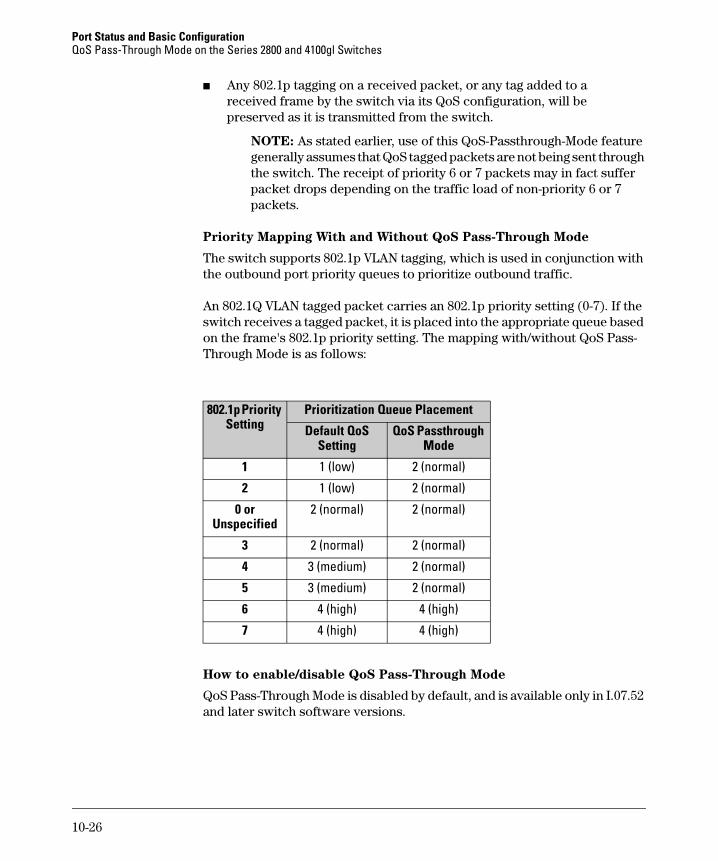
Port Status and Basic Configuration QoS Pass-Through Mode on the Series 2800 and 4100gl Switches
■ Any 802.1p tagging on a received packet, or any tag added to a received frame by the switch via its QoS configuration, will be preserved as it is transmitted from the switch.
NOTE: As stated earlier, use of this QoS-Passthrough-Mode feature generally assumes that QoS tagged packets are not being sent through the switch. The receipt of priority 6 or 7 packets may in fact suffer packet drops depending on the traffic load of non-priority 6 or 7 packets.
Priority Mapping With and Without QoS Pass-Through Mode
The switch supports 802.1p VLAN tagging, which is used in conjunction with the outbound port priority queues to prioritize outbound traffic.
An 802.1Q VLAN tagged packet carries an 802.1p priority setting (0-7). If the switch receives a tagged packet, it is placed into the appropriate queue based on the frame's 802.1p priority setting. The mapping with/without QoS Pass-Through Mode is as follows:
802.1p Priority Setting
Prioritization Queue Placement
Default QoS Setting
QoS Passthrough Mode
1 1 (low) 2 (normal)
2 1 (low) 2 (normal)
0 or Unspecified
2 (normal) 2 (normal)
3 2 (normal) 2 (normal)
4 3 (medium) 2 (normal)
5 3 (medium) 2 (normal)
6 4 (high) 4 (high)
7 4 (high) 4 (high)
How to enable/disable QoS Pass-Through Mode
QoS Pass-Through Mode is disabled by default, and is available only in I.07.52 and later switch software versions.
10-26
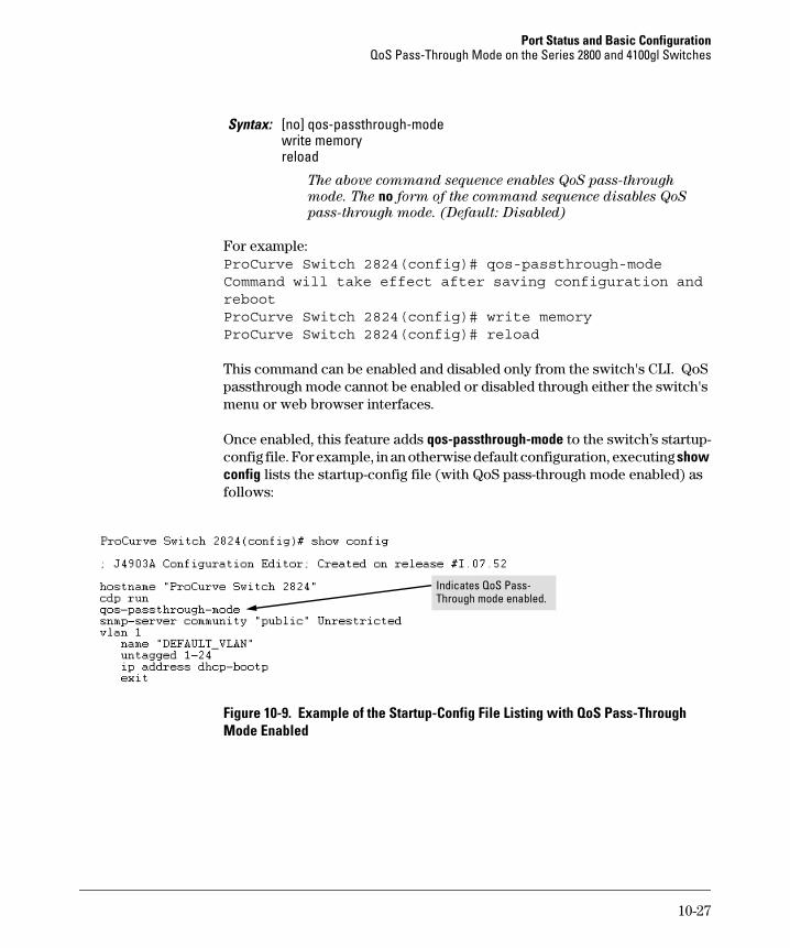
Port Status and Basic Configuration QoS Pass-Through Mode on the Series 2800 and 4100gl Switches
Syntax: [no] qos-passthrough-modewrite memoryreload
The above command sequence enables QoS pass-through
mode. The no form of the command sequence disables QoS
pass-through mode. (Default: Disabled)
For example: ProCurve Switch 2824(config)# qos-passthrough-modeCommand will take effect after saving configuration and rebootProCurve Switch 2824(config)# write memoryProCurve Switch 2824(config)# reload
This command can be enabled and disabled only from the switch's CLI. QoS passthrough mode cannot be enabled or disabled through either the switch's menu or web browser interfaces.
Once enabled, this feature adds qos-passthrough-mode to the switch’s startupconfig file. For example, in an otherwise default configuration, executing show config lists the startup-config file (with QoS pass-through mode enabled) as follows:
Indicates QoS Pass-Through mode enabled.
Figure 10-9. Example of the Startup-Config File Listing with QoS Pass-Through Mode Enabled
10-27
Port Status and Basic Configuration Configuring Port-Based Priority for Incoming Packets on the 4100gl and 6108 Switches
Configuring Port-Based Priority for Incoming Packets on the 4100gl and 6108 Switches
Default MenuFeature CLI Web
Assigning a priority level to traffic on the basis Disabled n/a page 10-31 n/a of incoming port
When network congestion occurs, it is important to move traffic on the basis of relative importance. However, without prioritization:
■ Traffic from less important sources can consume bandwidth and slow down or halt delivery of more important traffic.
■ Most traffic from all ports is forwarded as normal priority, and competes for bandwidth with all other normal-priority traffic, regardless of its relative importance.
Traffic received in tagged VLAN packets carries a specific 802.1p priority level (0 - 7) that the switch recognizes and uses to assign packet priority at the outbound port. With the default port-based priority, the switch handles traffic received in untagged packets as “Normal” (priority level = 0).
You can assign a priority level to:
■ Inbound, untagged VLAN packets
■ Inbound, tagged VLAN packets having a priority level of 0 (zero)
(The switch does not alter the existing priority level of inbound, tagged VLAN packets carrying a priority level of 1-7.)
Thus, for example, high-priority tagged VLAN traffic received on a port retains its priority in the switch. However, you have the option of configuring the port to assign a priority level to untagged traffic and 0-priority tagged traffic the port receives.
The Role of 802.1Q VLAN Tagging
An 802.1Q-tagged VLAN packet carries the packet’s VLAN assignment and the 802.1p priority setting (0 - 7). (By contrast, an untagged packet does not have a tag and does not carry a priority setting.) Generally, the switch preserves and uses a packet’s priority setting to determine which outbound queue the packet belongs in on the outbound port. If the outbound port is a tagged
10-28
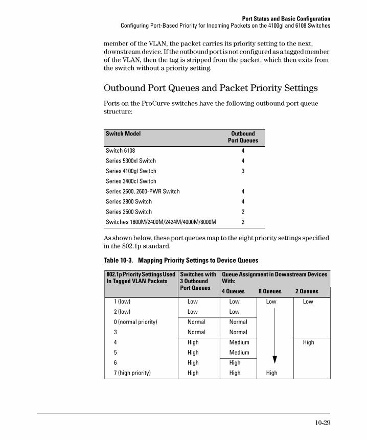
Port Status and Basic Configuration Configuring Port-Based Priority for Incoming Packets on the 4100gl and 6108 Switches
member of the VLAN, the packet carries its priority setting to the next, downstream device. If the outbound port is not configured as a tagged member of the VLAN, then the tag is stripped from the packet, which then exits from the switch without a priority setting.
Outbound Port Queues and Packet Priority Settings
Ports on the ProCurve switches have the following outbound port queue structure:
Port Queues
4
Switch Model Outbound
Switch 6108
Series 5300xl Switch 4
Series 4100gl Switch 3
Series 3400cl Switch
Series 2600, 2600-PWR Switch 4
Series 2800 Switch 4
Series 2500 Switch 2
Switches 1600M/2400M/2424M/4000M/8000M 2
As shown below, these port queues map to the eight priority settings specified in the 802.1p standard.
Table 10-3. Mapping Priority Settings to Device Queues
802.1p Priority Settings Used Switches with Queue Assignment in Downstream Devices In Tagged VLAN Packets 3 Outbound With:
Port Queues 4 Queues 8 Queues 2 Queues
1 (low) Low Low Low Low
2 (low) Low Low
0 (normal priority) Normal Normal
3 Normal Normal
4 High Medium High
5 High Medium
6 High High
7 (high priority) High High High
10-29
Port Status and Basic Configuration Configuring Port-Based Priority for Incoming Packets on the 4100gl and 6108 Switches
For example, suppose you have configured port A10 to assign a priority level of 1 (low):
■ An untagged packet coming into the switch on port A10 and leaving the switch through any other port configured as a tagged VLAN member would leave the switch as a tagged packet with a priority level of 1.
■ A tagged packet with an 802.1p priority setting of 0 (zero) coming into the switch on port A10 and leaving the switch through any other port configured as a tagged VLAN member would leave the switch as a tagged packet with a priority level of 1.
■ A tagged packet with an 802.1p priority setting (1 - 7) coming into the switch on port A10 and leaving the switch through any other port configured as a tagged VLAN member would keep its original priority setting (regardless of the port-based priority setting on port A10).
N o t e For a packet to carry a given 802.1p priority level from end-to-end in a network, the VLAN for the packet must be configured as tagged on all switch-to-switch links. Otherwise the tag is removed and the 802.1p priority is lost as the packet moves from one switch to the next.
Operating Rules for Port-Based Priority
These rules apply to the operation of port-based priority on the switch.
■ In the switch’s default configuration, port-based priority is configured as “0” (zero) for inbound traffic on all ports.
■ On a given port, when port-based priority is configured as 0 - 7, an inbound, untagged packet adopts the specified priority and is sent to the corresponding outbound queue on the outbound port. (See table 10-3, “Mapping Priority Settings to Device Queues”, on page 10-29.) If the outbound port is a tagged member of the applicable VLAN, then the packet carries a tag with that priority setting to the next downstream device.
■ On a given port, when port-based priority is configured as 0 - 7, an inbound, tagged packet with a priority of 0 (zero) adopts the specified priority and is sent to the corresponding outbound queue on the outbound port. (See table 10-3, “Mapping Priority Settings to Device Queues”, on page 10-29.) If the outbound port is a tagged member of the applicable VLAN, then the packet carries a tag with that priority setting to the next downstream device.
10-30
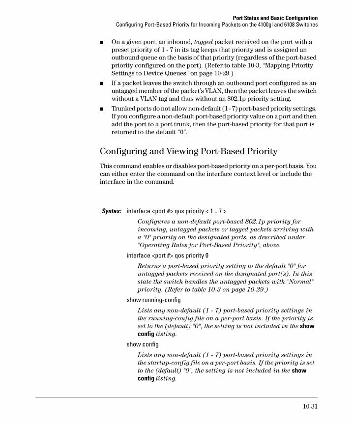
Port Status and Basic Configuration Configuring Port-Based Priority for Incoming Packets on the 4100gl and 6108 Switches
■ On a given port, an inbound, tagged packet received on the port with a preset priority of 1 - 7 in its tag keeps that priority and is assigned an outbound queue on the basis of that priority (regardless of the port-based priority configured on the port). (Refer to table 10-3, “Mapping Priority Settings to Device Queues” on page 10-29.)
■ If a packet leaves the switch through an outbound port configured as an untagged member of the packet’s VLAN, then the packet leaves the switch without a VLAN tag and thus without an 802.1p priority setting.
■ Trunked ports do not allow non-default (1 - 7) port-based priority settings. If you configure a non-default port-based priority value on a port and then add the port to a port trunk, then the port-based priority for that port is returned to the default “0”.
Configuring and Viewing Port-Based Priority
This command enables or disables port-based priority on a per-port basis. You can either enter the command on the interface context level or include the interface in the command.
Syntax: interface <port #> qos priority < 1 .. 7 >
Configures a non-default port-based 802.1p priority for
incoming, untagged packets or tagged packets arriving with
a "0" priority on the designated ports, as described under
"Operating Rules for Port-Based Priority", above.
interface <port #> qos priority 0
Returns a port-based priority setting to the default "0" for
untagged packets received on the designated port(s). In this
state the switch handles the untagged packets with "Normal"
priority. (Refer to table 10-3 on page 10-29.)
show running-config
Lists any non-default (1 - 7) port-based priority settings in
the running-config file on a per-port basis. If the priority is
set to the (default) "0", the setting is not included in the show config listing.
show config
Lists any non-default (1 - 7) port-based priority settings in
the startup-config file on a per-port basis. If the priority is set
to the (default) "0", the setting is not included in the show config listing.
10-31
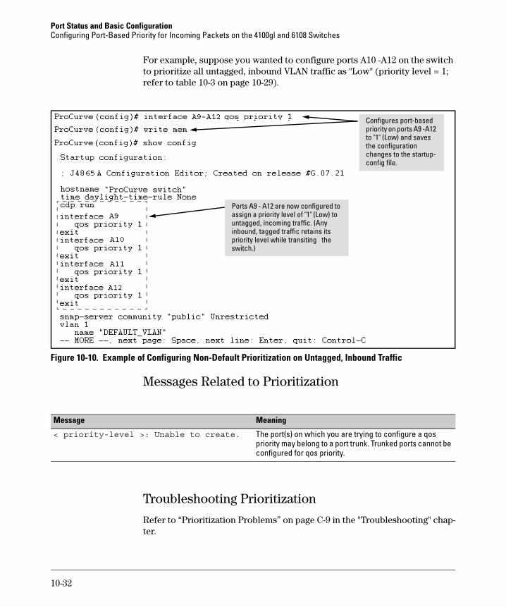
Port Status and Basic Configuration Configuring Port-Based Priority for Incoming Packets on the 4100gl and 6108 Switches
For example, suppose you wanted to configure ports A10 -A12 on the switch to prioritize all untagged, inbound VLAN traffic as "Low" (priority level = 1; refer to table 10-3 on page 10-29).
Ports A9 - A12 are now configured to assign a priority level of "1" (Low) to untagged, incoming traffic. (Any inbound, tagged traffic retains its priority level while transiting the switch.)
Configures port-based priority on ports A9 -A12 to "1" (Low) and saves the configuration changes to the startupconfig file.
Figure 10-10. Example of Configuring Non-Default Prioritization on Untagged, Inbound Traffic
Messages Related to Prioritization
Message Meaning
< priority-level >: Unable to create. The port(s) on which you are trying to configure a qos priority may belong to a port trunk. Trunked ports cannot be configured for qos priority.
Troubleshooting Prioritization
Refer to “Prioritization Problems” on page C-9 in the "Troubleshooting" chapter.
10-32
Port Status and Basic Configuration Using Friendly (Optional) Port Names
Using Friendly (Optional) Port Names
Feature Menu CLIDefault Web
Configure Friendly Port Names Standard Port n/a page 34 n/a Numbering
Display Friendly Port Names n/a n/a page 36 n/a
This feature enables you to assign alphanumeric port names of your choosing to augment automatically assigned numeric port names. This means you can configure meaningful port names to make it easier to identify the source of information listed by some Show commands. (Note that this feature augments
port numbering, but does not replace it.)
Configuring and Operating Rules for Friendly Port Names
■ At either the global or context configuration level you can assign a unique name to any port on the switch. You can also assign the same name to multiple ports.
■ The friendly port names you configure appear in the output of the show name [port-list], show config, and show interface <port-number> commands. They do not appear in the output of other show commands or in Menu interface screens. (See “Displaying Friendly Port Names with Other Port Data” on page 10-36.)
■ Friendly port names are not a substitute for port numbers in CLI commands or Menu displays.
■ Trunking ports together does not affect friendly naming for the individual ports. (If you want the same name for all ports in a trunk, you must individually assign the name to each port.)
■ A friendly port name can have up to 64 contiguous alphanumeric characters.
■ Blank spaces within friendly port names are not allowed, and if used, cause an invalid input error. (The switch interprets a blank space as a name terminator.)
■ In a port listing, not assigned indicates that the port does not have a name assignment other than its fixed port number.
10-33
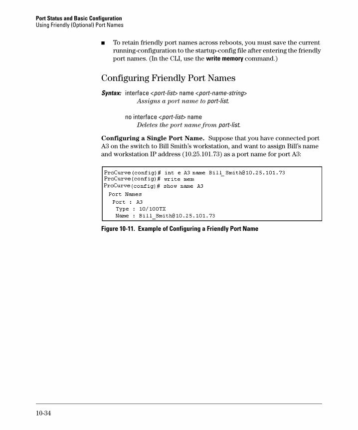
Port Status and Basic Configuration Using Friendly (Optional) Port Names
■ To retain friendly port names across reboots, you must save the current running-configuration to the startup-config file after entering the friendly port names. (In the CLI, use the write memory command.)
Configuring Friendly Port Names
Syntax: interface <port-list> name <port-name-string> Assigns a port name to port-list.
no interface <port-list> name Deletes the port name from port-list.
Configuring a Single Port Name. Suppose that you have connected port A3 on the switch to Bill Smith’s workstation, and want to assign Bill’s name and workstation IP address (10.25.101.73) as a port name for port A3:
Figure 10-11. Example of Configuring a Friendly Port Name
10-34
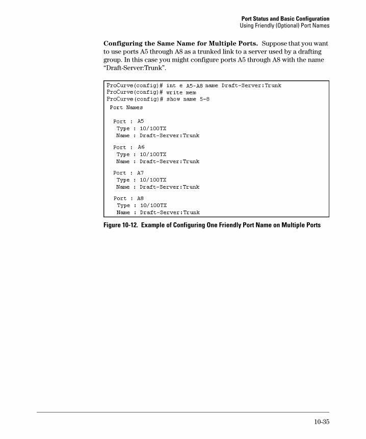
Port Status and Basic Configuration Using Friendly (Optional) Port Names
Configuring the Same Name for Multiple Ports. Suppose that you want to use ports A5 through A8 as a trunked link to a server used by a drafting group. In this case you might configure ports A5 through A8 with the name “Draft-Server:Trunk”.
Figure 10-12. Example of Configuring One Friendly Port Name on Multiple Ports
10-35
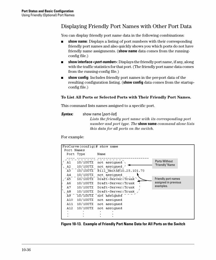
Port Status and Basic Configuration Using Friendly (Optional) Port Names
Displaying Friendly Port Names with Other Port Data
You can display friendly port name data in the following combinations:
■ show name: Displays a listing of port numbers with their corresponding friendly port names and also quickly shows you which ports do not have friendly name assignments. (show name data comes from the runningconfig file.)
■ show interface <port-number>: Displays the friendly port name, if any, along with the traffic statistics for that port. (The friendly port name data comes from the running-config file.)
■ show config: Includes friendly port names in the per-port data of the resulting configuration listing. (show config data comes from the startupconfig file.)
To List All Ports or Selected Ports with Their Friendly Port Names.
This command lists names assigned to a specific port.
Syntax: show name [port-list] Lists the friendly port name with its corresponding port
number and port type. The show name command alone lists
this data for all ports on the switch.
For example:
Fri i
Ports Without "Fri l
endly port names assigned n previous examples.
end y" Name
Figure 10-13. Example of Friendly Port Name Data for All Ports on the Switch
10-36
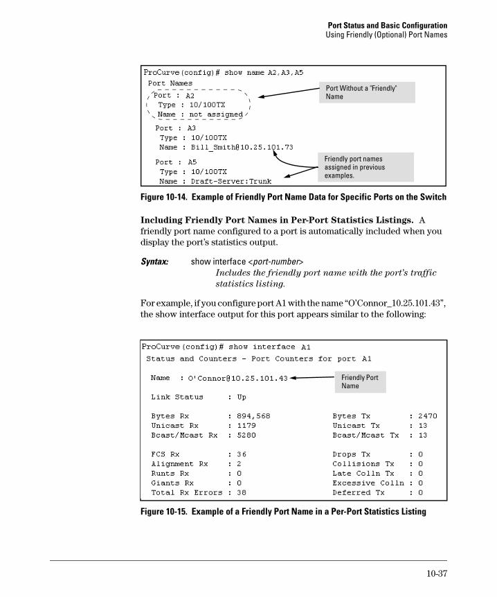
Port Status and Basic Configuration Using Friendly (Optional) Port Names
iPort Without a "Fr endly" Name
l
les.
Friend y port names assigned in previous examp
Figure 10-14. Example of Friendly Port Name Data for Specific Ports on the Switch
Including Friendly Port Names in Per-Port Statistics Listings. A friendly port name configured to a port is automatically included when you display the port’s statistics output.
Syntax: show interface <port-number> Includes the friendly port name with the port’s traffic
statistics listing.
For example, if you configure port A1 with the name “O’Connor_10.25.101.43”, the show interface output for this port appears similar to the following:
Friendly Port Name
Figure 10-15. Example of a Friendly Port Name in a Per-Port Statistics Listing
10-37
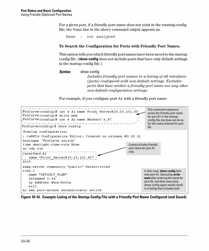
Port Status and Basic Configuration Using Friendly (Optional) Port Names
For a given port, if a friendly port name does not exist in the running-config file, the Name line in the above command output appears as:
Name : not assigned
To Search the Configuration for Ports with Friendly Port Names.
This option tells you which friendly port names have been saved to the startupconfig file. (show config does not include ports that have only default settings in the startup-config file.)
Syntax: show config Includes friendly port names in a listing of all interfaces
(ports) configured with non-default settings. Excludes
ports that have neither a friendly port name nor any other
non-default configuration settings.
For example, if you configure port A1 with a friendly port name:
In this case,
mem i
ii i l
l
This command sequence saves the friendly port name for port A1 in the startupconfig file, but does not do so for the name entered for port A2.
show config lists only port A1. Executing write
after enter ng the name for port A2, and then executing show config aga n would result n a l sting that inc udes both
Listing inc udes friendly port name for port A1 only.
Figure 10-16. Example Listing of the Startup-Config File with a Friendly Port Name Configured (and Saved)
10-38
11
Power Over Ethernet (PoE) Operation for the Series 2600-PWR Switches
Contents
Overview . . . . . . . . . . . . . . . . . . . . . . . . . . . . . . . . . . . . . . . . . . . . . . . . . . . . . 11-2
Configuration Options . . . . . . . . . . . . . . . . . . . . . . . . . . . . . . . . . . . . . . 11-2
Related Publications . . . . . . . . . . . . . . . . . . . . . . . . . . . . . . . . . . . . . . . . 11-3
Terminology . . . . . . . . . . . . . . . . . . . . . . . . . . . . . . . . . . . . . . . . . . . . . . . 11-3
Power Availability and Provisioning . . . . . . . . . . . . . . . . . . . . . . . . . . . . . . 11-4
Powered Device (PD) Support . . . . . . . . . . . . . . . . . . . . . . . . . . . . . . . 11-4
Power Priority . . . . . . . . . . . . . . . . . . . . . . . . . . . . . . . . . . . . . . . . . . . . . 11-5
Configuring PoE Operation . . . . . . . . . . . . . . . . . . . . . . . . . . . . . . . . . . . . . . 11-7
Cycling Power on a Port . . . . . . . . . . . . . . . . . . . . . . . . . . . . . . . . . . . . . 11-8
PoE for Pre-802.3af-standard PDs (Switch 2600-8-PWR) . . . . . . . . . . 11-9
Viewing PoE Configuration and Status . . . . . . . . . . . . . . . . . . . . . . . . . . . 11-10
Displaying the Switch’s Global PoE Power Status . . . . . . . . . . . . . . 11-10
Displaying an Overview of PoE Status on All Ports . . . . . . . . . . . . . 11-11
Displaying the PoE Status on Specific Ports . . . . . . . . . . . . . . . . . . . 11-12
Planning and Implementing a PoE Configuration . . . . . . . . . . . . . . . . . . 11-13
Assigning PoE Ports to VLANs . . . . . . . . . . . . . . . . . . . . . . . . . . . . . . 11-13
Applying Security Features to PoE Configurations . . . . . . . . . . . . . 11-13
PoE Event Log Messages . . . . . . . . . . . . . . . . . . . . . . . . . . . . . . . . . . . . . . . 11-14
11-1
Power Over Ethernet (PoE) Operation for the Series 2600-PWR Switches Overview
Overview Power Over Ethernet (PoE) technology allows IP telephones, wireless LAN access points, and other powered devices (PDs) to receive power and transfer data over existing LAN cabling.
The PoE feature described in this chapter operates on the following switches (referred to collectively as the Series 2600-PWR switches):
■ ProCurve Switch 2600-8-PWR (J8762A)
■ ProCurve Switch 2626-PWR (J8164A)
■ ProCurve Switch 2650-PWR (J8165A)
The switches provision their 10/100Base-TX ports with power for PoE applications compatible with the IEEE 802.3af standard. The PoE ports on your switch support both standard networking links and PoE links. Thus, you can connect either a non-PoE device or a powered device (PD) to a PoE-enabled port without reconfiguring the port.
Configuration Options
In the default configuration, all 10/100Base-TX ports on the switch support PoE operation. Using the commands described in this chapter, you can:
■ Configure a power threshold for SNMP and Event Log reporting of PoE consumption on the switch.
■ Configure per-port priority for allocating power in case the switch becomes oversubscribed and must drop power for some lower-priority ports to support the demand on other, higher-priority ports.
■ Disable or re-enable per-port PoE operation on some ports to help control power usage and avoid oversubscribing PoE on the switch. (In the default configuration, the switch enables PoE on all 10/100-TX ports, subject to PoE priority in the case of oversubscription of PoE resources.)
■ Disable or re-enable PoE for pre-802.3af-standard powered devices (Switch 2600-8-PWR only).
■ Monitor PoE status and performance on the switch.
See “Configuring PoE Operation” on page 11-7 for further details.
11-2
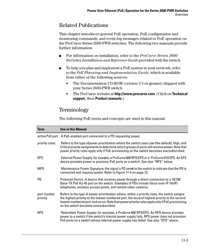
Power Over Ethernet (PoE) Operation for the Series 2600-PWR Switches Overview
Related Publications
This chapter introduces general PoE operation, PoE configuration and monitoring commands, and event log messages related to PoE operation on the ProCurve Series 2600-PWR switches. The following two manuals provide further information:
■ For information on installation, refer to the ProCurve Series 2600
Switches Installation and Reference Guide provided with the switch.
■ To help you plan and implement a PoE system in your network, refer to the PoE Planning and Implementation Guide, which is available from either of the following sources:
• The Documentation CD-ROM (version 3.5 or greater) shipped with your Series 2600-PWR switch
• The ProCurve website at http://www.procurve.com. (Click on Technical support, then Product manuals.)
Terminology
The following PoE terms and concepts are used in this manual.
Term Use in this Manual
active PoE port A PoE-enabled port connected to a PD requesting power.
priority class Refers to the type of power prioritization where the switch uses Low (the default), High, and Critical priority assignments to determine which groups of ports will receive power. Note that power priority rules apply only if PoE provisioning on the switch becomes oversubscribed.
EPS External Power Supply; for example, a ProCurve 600 RPS/EPS or a ProCurve 610 EPS. An EPS device provides power to provision PoE ports on a switch. See also “RPS” below.
MPS Maintenance Power Signature; the signal a PD sends to the switch to indicate that the PD is connected and requires power. Refer to Figure 11-4 on page 13.
PD Powered Device. A device that receives power through a direct connection to a 10/100 Base-TX PoE RJ-45 port on the switch. Examples of PDs include Voice-over-IP (VoIP) telephones, wireless access points, and remote video cameras.
port-number Refers to the type of power prioritization where, within a priority class, the switch assigns priority the highest priority to the lowest-numbered port, the second-highest priority to the second
lowest-numbered port, and so-on. Note that power priority rules apply only if PoE provisioning on the switch becomes oversubscribed.
RPS Redundant Power Supply; for example, a ProCurve 600 RPS/EPS. An RPS device provides power to a switch if the switch’s internal power supply fails. RPS power does not provision PoE ports on a switch whose internal power supply has failed. See also “EPS” above.
11-3
Power Over Ethernet (PoE) Operation for the Series 2600-PWR Switches Power Availability and Provisioning
Power Availability and Provisioning
Powered Device (PD) Support The switch must have a minimum of 15.4 watts of unused PoE power available when you connect an 802.3af-compliant PD, regardless of how much power the PD actually uses. On the Switch 2626-PWR and Switch 2600-8-PWR, there will always be enough power available to connect and support 802.3af PoE operation on all 10/100-TX ports. On the Switch 2650-PWR, however, it is possible to oversubscribe the available PoE power. In this case, one or more PoE devices connected to the switch will lose power. That is:
■ Sufficient PoE Power Available: When a Switch 2650-PWR detects a new PD, and if the switch has a minimum of 15.4 watts of PoE power available, the switch supplies power to the port for that PD.
■ Insufficient PoE Power Available: When a Switch 2650-PWR detects a new PD, and if the switch does not have a minimum of 15.4 watts of unused PoE power available:
• If the new PD is connected to a port “X” having a higher PoE priority than another port “Y”, the switch removes PoE power from port “Y” and delivers it to port “X”. In this case the PD on port “X” receives power and the PD on port “Y” is denied power.
• If the new PD is connected to a port “X” having a lower priority than all other PoE ports currently providing power to PDs, then the switch does not deliver PoE power to port “X”.
Note that once a PD connects to a port and begins operating, the port retains only enough PoE power to support the PD’s operation. Unneeded power becomes available for supporting other PD connections. Thus, while 15.4 watts must be available for the switch to begin supplying power to a port with a PD connected, 15.4 watts per port is not continually required if the connected PD requires less power.
For example, with 20 watts of PoE power remaining available on the switch, you can connect one new PD without losing power to any currently connected PDs. If that PD draws only 3 watts, then 17 watts remain available and you can connect at least one more PD without interrupting power to any other devices. If the next PD you connect draws 5 watts, then only 12 watts remain unused. With only 12 watts available, if you connect yet another PD, the lowest-priority port will lose PoE power until the switch once again has 15.4 or more watts available. (For information on power priority, refer to “Power Priority” on page 11-5.)
11-4

Power Over Ethernet (PoE) Operation for the Series 2600-PWR Switches Power Availability and Provisioning
Disconnecting a PD from a port causes the switch to stop providing PoE power to that port and makes the power available to other ports configured for PoE operation. If the PoE demand becomes greater than the available power, the switch transfers power from lower-priority ports to higher-priority ports. (Ports not currently providing power to PDs are not affected.)
Note 15.4 watts of available power is required for the switch to begin delivering power to a port, such as when a newly connected PD is detected or when power is released from higher priority ports. Depending on power demands, lower-priority ports on a switch with high PoE power demand may occasionally lose power due to the demands of higher-priority ports. (Refer to “Power Priority” for further details.)
Power Priority
In the default configuration PoE power priority is determined by port number, with the lowest numbered port having the highest priority.
When Does the Switch Prioritize Power Allocations? If the switch can provide power for all existing PD demands, it does not use its power priority settings to allocate power. However, if the PD power demand oversubscribes the available power, then the switch prioritizes the power allocation to the ports that present a PD power demand. This causes the switch to remove power from one or more lower-priority ports to meet the power demand on other, higher-priority ports. (This operation occurs, regardless of the order in which PDs connect to the switch’s PoE-configured ports.)
How Does the Switch Prioritize Power Allocations? The switch simultaneously uses two priority methods:
■ The priority class method enables port PoE priority class assignments of Low (the default), High, and Critical.
■ The port-number priority method gives a lower-numbered port priority over a higher-numbered port within the same configured priority class.
On the Switch 2650-PWR, the ports configured with the highest priority of either bank (1-24 or 25-48) will receive PoE power, regardless of position. There is also an option to provision ports 1-24 with 406 watts of internal power and ports 25-48 with 408 watts of external power by adding an external power supply. For more information on using external power supplies with PoE-capable switches, refer to the PoE Planning and Implementation Guide.
11-5

Power Over Ethernet (PoE) Operation for the Series 2600-PWR Switches Power Availability and Provisioning
Table 11-1 provides examples of how PoE priority settings impact operation.
Table 11-1. Example of PoE Priority Operation
Port 1Priority Setting
Configuration Command and Resulting Operation
25 - 48 Critical This priority class always receives power. If there is not enough power to provision PDs on all of the ports configured for this class, then no power goes to ports configured for High and Low priority. If there is enough power to provision PDs on only some of the “Critical” ports, then power is allocated to the “Critical” ports in ascending order, beginning with the lowest-numbered port in the class, which, in this case, is port 25. For this example, the CLI command to set ports to “Critical” is:
ProCurve(config)# interface e 25-48 power critical
9 - 12 High This priority class receives power only if all PDs on ports with a Critical priority setting are receiving full power. If there is not enough power to provision PDs on all ports with a High priority, then no power goes to ports with a Low priority. If there is enough power to provision PDs on only some of the “High” ports, then power is allocated to the “High” ports in ascending order, beginning, in this example, with port 9, until all available power is in use. For this example, the CLI command to set ports to “High” is:
ProCurve(config)# interface e 9-12 power high
1 - 8 Low This priority class receives power only if all PDs on ports with High and Critical priority settings are receiving power. If there is enough power to provision PDs on only some Low priority ports, then power is allocated to the ports in ascending order, beginning with the lowest-numbered port in the class (port 1, in this case), until all available power is in use. For this example, the CLI command to set ports to “Low”2 is:
ProCurve(config)# interface e 1-8 power low
13 - 24 - n/a For this example, PoE is disabled on these ports. The CLI command for this setting is:
ProCurve(config)# no interface e 13-24 power
1 For a listing of PoE configuration commands, with descriptions, refer to “Configuring PoE Operation” on page 11-7. 2 In the default PoE configuration, the ports are already set to the low priority. In this case, the command is not necessary.
11-6
Power Over Ethernet (PoE) Operation for the Series 2600-PWR Switches Configuring PoE Operation
Configuring PoE Operation
By default, PoE support is enabled on the switch’s 10/100Base-TX ports, with the power priority set to Low and the power threshold set to 80 (%). The following commands allow you to adjust these settings.
Syntax: power threshold < 1 - 99 >
The power threshold is a configurable percentage of the total
PoE power available on the switch. When PoE consumption
exceeds the threshold, the switch automatically generates an
SNMP trap and also sends a message to the Event Log. For
example, if the power threshold is set to 80% (the default), and
an increasing PoE power demand crosses this threshold, the
switch sends an SNMP trap and generates this Event Log
message:
PoE usage has exceeded threshold of 80 %.If the switch is configured for debug logging, it also sends the
same message to the configured debug destination(s).
The switch automatically invokes the power threshold at the
global configuration level with a default setting of 80%. You
can configure the power threshold to a value in the range of
1% to 99%.
If an increasing PoE power load (1) exceeds the configured
power threshold (which triggers the log message and SNMP
trap), and then (2) later begins decreasing and drops below
the threshold again, the switch generates another SNMP trap,
plus a message to the Event Log and any configured Debug
destinations. To continue the above example:
PoE usage is below configured threshold of 80 %.
(Refer to “PoE Event Log Messages” on page 11-14.)
Syntax: [no] interface [e] < port-list > power
Re-enables PoE operation on < port-list > and restores the
priority setting in effect when PoE was disabled on
< port-list >. The [no] form of the command disables PoE
operation on < port-list >. (Default: All 10/100Base-TX ports on
the switch enabled for PoE operation at Low priority.)
11-7

Power Over Ethernet (PoE) Operation for the Series 2600-PWR Switches Configuring PoE Operation
Syntax: interface [e] < port-list > power [ critical | high | low ]
Reconfigures the PoE priority level on < port-list >. For a given
level, the switch automatically prioritizes ports by port
number (in ascending order). If there is not enough power
available to provision all active PoE ports at a given priority
level, then the lowest-numbered port at that level will be
provisioned first, and so on. The switch invokes configured
PoE priorities only when it cannot provision all active PoE
ports.
• Critical: Specifies the highest priority PoE support for < port-list >. The switch provisions active PoE ports at this level
before PDs connected to any other ports.
• High: Specifies the second highest priority PoE support for
< port-list >. The switch provisions active PoE ports at this
level before PDs connected to Low-priority ports.
• Low (the default): Specifies the lowest priority PoE support
for < port-list >. The switch provisions active PoE ports at
this level only if there is power available after provisioning
any active PoE ports at the higher priority levels.
Cycling Power on a Port
Simply disabling a PoE port does not affect power delivery through that port. To cycle the power on a PD receiving power from a PoE port on the switch, disable, then re-enable the power to that port.
For example, to cycle the power on a PoE device connected to port 1 on a 2600-PWR switch:
ProCurve(config)# no interface 1 powerProCurve(config)# interface 1 power
11-8
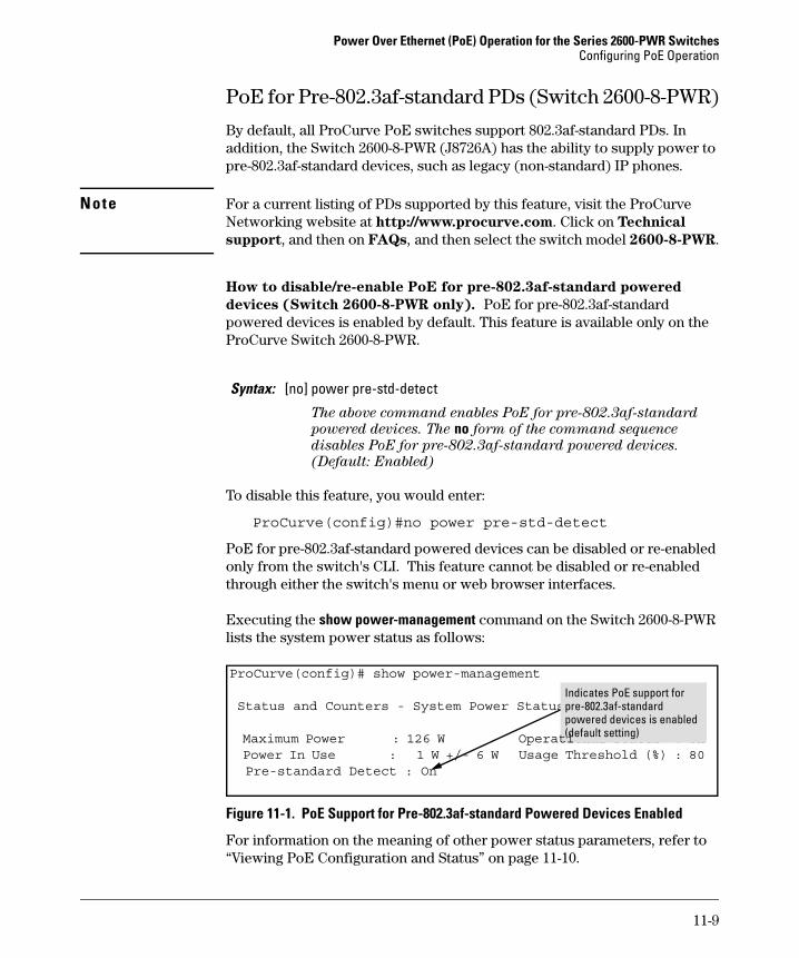
Power Over Ethernet (PoE) Operation for the Series 2600-PWR Switches Configuring PoE Operation
onal Status : On
PoE for Pre-802.3af-standard PDs (Switch 2600-8-PWR)
By default, all ProCurve PoE switches support 802.3af-standard PDs. In addition, the Switch 2600-8-PWR (J8726A) has the ability to supply power to pre-802.3af-standard devices, such as legacy (non-standard) IP phones.
Note For a current listing of PDs supported by this feature, visit the ProCurve Networking website at http://www.procurve.com. Click on Technical
support, and then on FAQs, and then select the switch model 2600-8-PWR.
How to disable/re-enable PoE for pre-802.3af-standard powered
devices (Switch 2600-8-PWR only). PoE for pre-802.3af-standard powered devices is enabled by default. This feature is available only on the ProCurve Switch 2600-8-PWR.
Syntax: [no] power pre-std-detect
The above command enables PoE for pre-802.3af-standard
powered devices. The no form of the command sequence
disables PoE for pre-802.3af-standard powered devices.
(Default: Enabled)
To disable this feature, you would enter:
ProCurve(config)#no power pre-std-detect
PoE for pre-802.3af-standard powered devices can be disabled or re-enabled only from the switch's CLI. This feature cannot be disabled or re-enabled through either the switch's menu or web browser interfaces.
Executing the show power-management command on the Switch 2600-8-PWR lists the system power status as follows:
ProCurve(config)# show power-management
Status and Counters - System Power Status
)
Pre-standard Detect : On
Indicates PoE support forpre-802.3af-standard powered devices is enabled (default setting Maximum Power : 126 W Operati
Power In Use : 1 W +/- 6 W Usage Threshold (%) : 80
Figure 11-1. PoE Support for Pre-802.3af-standard Powered Devices Enabled
For information on the meaning of other power status parameters, refer to “Viewing PoE Configuration and Status” on page 11-10.
11-9

Power Over Ethernet (PoE) Operation for the Series 2600-PWR Switches Viewing PoE Configuration and Status
Viewing PoE Configuration and Status
Displaying the Switch’s Global PoE Power Status
Syntax:show power-management
Displays the switch’s global PoE power status, including:
• Max Power: Lists the maximum PoE wattage available to
provision active PoE ports on the switch.
• Power In Use: Lists the amount of PoE power presently in use.
• Operational Status: Indicates whether PoE power is available
on the switch. (Default: On ; shows Off if PoE power is not
available. Shows Faulty if internal or external PoE power is
oversubscribed or faulty.)
• Usage Threshold (%): Lists the configured percentage of
available PoE power provisioning the switch must exceed to
generate a usage notice in the form of an Event Log message
and an SNMP trap. If this event is followed by a drop in power
provisioning below the threshold, the switch generates
another SNMP trap and Event Log message. Event Log
messages are also sent to any optionally configured debug
destinations. (Default: 80%)
• Pre-standard Detect (Switch 2600-8-PWR only): Shows whether
PoE for pre-802.3af-standard powered devices is enabled on
the switch. (Default: On ; shows Off when PoE for
pre-802.3af-standard powered devices has been disabled.)
For example, in the default PoE configuration, when the switch is running with several ports supporting PD loads, show power-management displays data similar to the following on a Switch 2626-PWR device:
Figure 11-2. Example of Show Power-Management Output
11-10
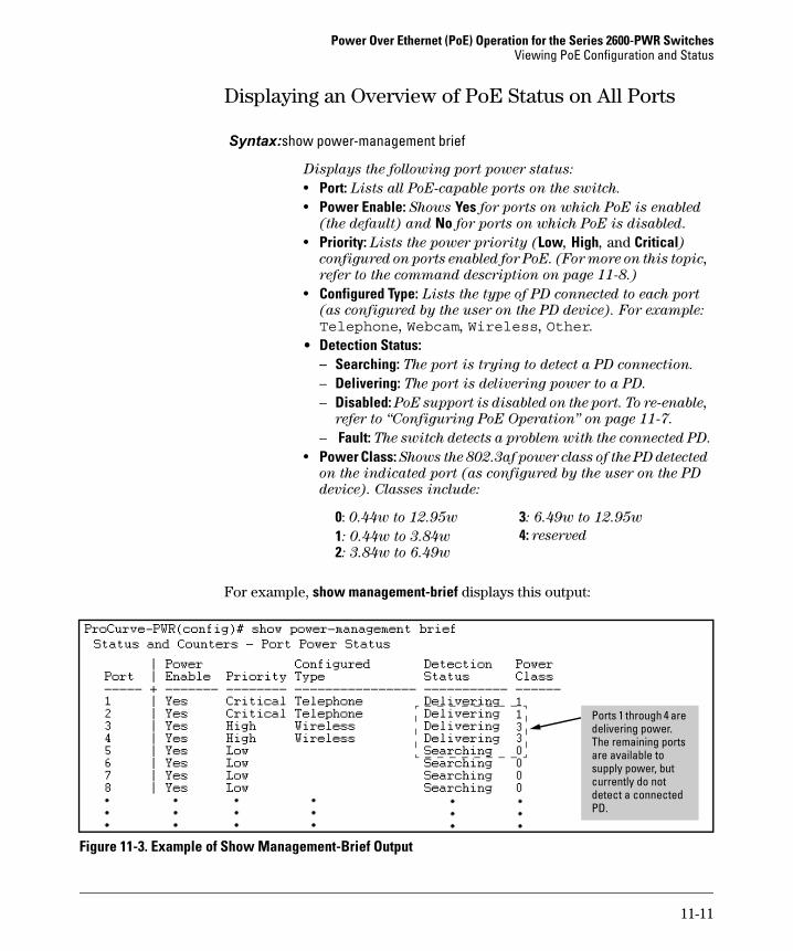
Power Over Ethernet (PoE) Operation for the Series 2600-PWR Switches Viewing PoE Configuration and Status
Displaying an Overview of PoE Status on All Ports
Syntax:show power-management brief
Displays the following port power status:
• Port: Lists all PoE-capable ports on the switch.
• Power Enable: Shows Yes for ports on which PoE is enabled
(the default) and No for ports on which PoE is disabled. • Priority: Lists the power priority (Low, High, and Critical)
configured on ports enabled for PoE. (For more on this topic,
refer to the command description on page 11-8.)
• Configured Type: Lists the type of PD connected to each port
(as configured by the user on the PD device). For example:
Telephone, Webcam, Wireless, Other.
• Detection Status: – Searching: The port is trying to detect a PD connection.
– Delivering: The port is delivering power to a PD.
– Disabled: PoE support is disabled on the port. To re-enable,
refer to “Configuring PoE Operation” on page 11-7.
– Fault: The switch detects a problem with the connected PD. • Power Class: Shows the 802.3af power class of the PD detected
on the indicated port (as configured by the user on the PD
device). Classes include:
0: 0.44w to 12.95w 3: 6.49w to 12.95w
1: 0.44w to 3.84w 4: reserved
2: 3.84w to 6.49w
For example, show management-brief displays this output:
Ports 1 through 4 are delivering power. The remaining ports are available to supply power, but currently do not detect a connected PD.
Figure 11-3. Example of Show Management-Brief Output
11-11
Power Over Ethernet (PoE) Operation for the Series 2600-PWR Switches Viewing PoE Configuration and Status
Displaying the PoE Status on Specific Ports
Syntax:show power-management [e] < port-list >
Displays the following PoE status and statistics (since the last
reboot) for each port in < port-list >: • Power Enable: Shows Yes for ports enabled to support PoE (the
default) and No for ports on which PoE is disabled. • Priority: Lists the power priority (Low, High, and Critical)
configured on ports enabled for PoE. (For more on this topic,
refer to the power command description under “Configuring
PoE Operation” on page 11-7.)
• Detection Status: – Searching: The port is available to support a PD connection.
– Delivering: The port is delivering power to a PD.
– Disabled: PoE support is disabled on the port. To re-enable
PoE support, refer to “Configuring PoE Operation” on
page 11-7.
– Fault: The switch detects a problem with the connected PD.
• Over Current Cnt: Shows the number of times a connected PD
has attempted to draw more than 15.4 watts. Each
occurrence generates an Event Log message.
• Power Denied Cnt: Shows the number of times PDs requesting
power on the port have been denied due to insufficient power
available. Each occurrence generates an Event Log message.
• Voltage: The total voltage, in dV, being delivered to PDs. • Power: The total power, in mW, being delivered to PDs. • Configured Type: Shows the type of PD detected on the port.
• Power Class: Shows the power class of the PD detected on the indicated port. Classes include:
0: 0.44w to 12.95w 3: 6.49w to 12.95w
1: 0.44w to 3.84w 4: reserved
2: 3.84w to 6.49w
• MPS Absent Cnt: This value shows the number of times a
detected PD has no longer requested power from the port.
Each occurrence generates an Event Log message. (“MPS”
refers to the “Maintenance Power Signature”. Refer to
“Terminology” on page 11-3.)
• Short Cnt: Shows the number of times the switch provided
insufficient current to a connected PD.
• Current: The total current, in mA, being delivered to PDs.
11-12
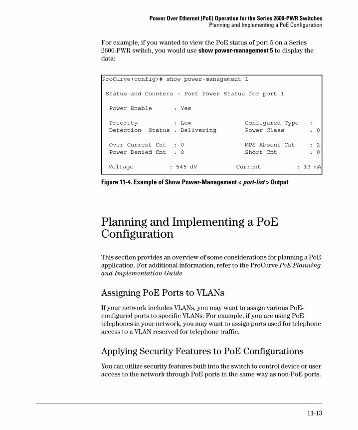
Power Over Ethernet (PoE) Operation for the Series 2600-PWR Switches Planning and Implementing a PoE Configuration
For example, if you wanted to view the PoE status of port 5 on a Series 2600-PWR switch, you would use show power-management 5 to display the data:
ProCurve(config)# show power-management 1
Status and Counters - Port Power Status for port 1
Power Enable : Yes
Priority : Low Configured Type : Detection Status : Delivering Power Class : 0
Over Current Cnt : 0 MPS Absent Cnt : 2 Power Denied Cnt : 0 Short Cnt : 0
Voltage : 545 dV Current : 13 mA
Figure 11-4. Example of Show Power-Management < port-list > Output
Planning and Implementing a PoE Configuration
This section provides an overview of some considerations for planning a PoE application. For additional information, refer to the ProCurve PoE Planning
and Implementation Guide.
Assigning PoE Ports to VLANs
If your network includes VLANs, you may want to assign various PoEconfigured ports to specific VLANs. For example, if you are using PoE telephones in your network, you may want to assign ports used for telephone access to a VLAN reserved for telephone traffic.
Applying Security Features to PoE Configurations
You can utilize security features built into the switch to control device or user access to the network through PoE ports in the same way as non-PoE ports.
11-13
Power Over Ethernet (PoE) Operation for the Series 2600-PWR Switches PoE Event Log Messages
■ MAC Address Security: Using Port Security, you can configure each switch port with a unique list of up to eight MAC addresses for devices that are authorized to access the network through that port. For more information, refer to the chapter titled “Configuring and Monitoring Port Security” in the Access Security Guide for your switch.
■ Username/Password Security: If you are connecting a device that allows you to enter a username and password that is forwarded to a networked server for authentication, then you can also configure the following security features:
– TACACS+ – RADIUS Authentication and Accounting – 802.1X Authentication
For more information, refer to the Access Security Guide for your switch.
PoE Event Log Messages
PoE operation generates these Event Log messages. You can also configure the switch to send these messages to a configured debug destination (terminal device or Syslog server).
I 1MM/DD/YY HH:MM:SS chassis:
Message header, with severity, date, system time, and system
module type. For more information on Event Log operation, refer
to the “Troubleshooting” appendix in the Management and
Configuration Guide for your switch.
Ext Power Supply connected, supplying < actual-power > W of < avail-power > W max.
The switch detected an EPS (External Power Supply) and began
receiving the wattage indicated by < actual-power >. The < avail-power > field indicates the maximum power (wattage) the
detected EPS is capable of delivering
Ext Power Supply disconnected
The switch has lost contact with an external power supply.
11-14

Power Over Ethernet (PoE) Operation for the Series 2600-PWR Switches PoE Event Log Messages
POE usage is below configured threshold of <1 - 99> % < slot-# > POE usage is below configured threshold of<1-99> %
Indicates that POE usage in the switch or indicated slot (if the
switch includes module slots) has decreased below the threshold
specified by the last execution of the global power threshold <1 - 99> command. This message occurs if, after the last reboot, the PoE
demand on the switch exceeded the power threshold and then later
dropped below the threshold value.
Port < port-# > applying power to PD.
A PoE device is connected to the port and receiving power.
Port < port-# > PD detected.
The switch has detected a PoE device connected to the port.
W MM/DD/YY HH:MM:SS chassis:
Message header, with severity, date, system time, and system
module type. For more information on Event Log operation, refer
to the “Troubleshooting” appendix in the Management and
Configuration Guide for your switch.
Ext Power Supply connected but not responding.
The switch detects an external power supply, but is not receiving
power from the device.
Ext Power Supply failure: < fault-type > Failures:
Indicates an external power supply failure where < fault-type > is
one of the following:
• Over Current fault: The ProCurve 600 RPS/EPS or ProCurve
610 EPS reported a fault condition. Contact your ProCurve
support representative.
• Fan fault: A fan in an external power supply has failed.
• Temperature fault: The operating temperature in an external
power supply has exceeded the normal operating range.
• 50V fault: The ProCurve 600 RPS/EPS or ProCurve 610 EPS
reported a fault condition. Contact your ProCurve support
representative.
• 12V fault: The ProCurve 600 RPS/EPS or ProCurve 610 EPS
reported a fault condition. Contact your ProCurve support
representative.
11-15

Power Over Ethernet (PoE) Operation for the Series 2600-PWR Switches PoE Event Log Messages
POE usage has exceeded threshold of < 1 - 99 > % < slot-# > POE usage has exceeded threshold of < 1 - 99 > %
Indicates that POE usage in the switch or indicated slot (if the
switch includes module slots) has exceeded the configured
threshold for the switch, as specified by the last execution of the
power threshold < 1 - 99 > command. (Note that the switch also
generates an SNMP trap for this event.)
Port < port-# > PD Denied power due to insufficient power allocation.
There is insufficient power available to power the PD on the
indicated port and the port does not have sufficient PoE priority
to take power from another active PoE port.
Port < port-# > PD Invalid Signature indication.
The switch has detected a non 802.3af-compliant load.
Port < port-# > PD MPS Absent indication.
The switch no longer detects a device on < port-# >. The device
may have been disconnected, powered down, or stopped
functioning.
Port < port-# > PD Other Fault indication.
There is a problem with the PD connected to the port.
Port < port-# > PD Over Current indication.
The PD connected to < port-# > has requested more than 15.4 watts
of power. This may indicate a short-circuit or other problem in
the PD.
11-16
12
Port Trunking
Contents
Overview . . . . . . . . . . . . . . . . . . . . . . . . . . . . . . . . . . . . . . . . . . . . . . . . . . . . . 12-2
Port Status and Configuration . . . . . . . . . . . . . . . . . . . . . . . . . . . . . . . . . . . 12-2
Trunk Group Boundary Requirement with IP Routing Enabled
Trunk Group Boundary Requirement for the Series 4100gl
Port Connections and Configuration . . . . . . . . . . . . . . . . . . . . . . . . . . 12-3Link Connections . . . . . . . . . . . . . . . . . . . . . . . . . . . . . . . . . . . . . . . 12-3
on the Series 2800 Switch . . . . . . . . . . . . . . . . . . . . . . . . . . . . . . . . 12-3
Switch 10/100/1000 Module (J4908A) . . . . . . . . . . . . . . . . . . . . . . 12-4
Port Trunk Options and Operation . . . . . . . . . . . . . . . . . . . . . . . . . . . . 12-5
Trunk Configuration Methods . . . . . . . . . . . . . . . . . . . . . . . . . . . . . . . . 12-5
Menu: Viewing and Configuring a Static Trunk Group . . . . . . . . . . . 12-10
CLI: Viewing and Configuring a Static or Dynamic PortTrunk Group . . . . . . . . . . . . . . . . . . . . . . . . . . . . . . . . . . . . . . . . . . . . . 12-12
Using the CLI To View Port Trunks . . . . . . . . . . . . . . . . . . . . . . . 12-12Using the CLI To Configure a Static or Dynamic Trunk Group 12-15
Web: Viewing Existing Port Trunk Groups . . . . . . . . . . . . . . . . . . . . 12-18
Trunk Group Operation Using LACP . . . . . . . . . . . . . . . . . . . . . . . . . 12-18Default Port Operation . . . . . . . . . . . . . . . . . . . . . . . . . . . . . . . . . 12-21LACP Notes and Restrictions . . . . . . . . . . . . . . . . . . . . . . . . . . . . 12-23
Trunk Group Operation Using the “Trunk” Option . . . . . . . . . . . . . . 12-25
How the Switch Lists Trunk Data . . . . . . . . . . . . . . . . . . . . . . . . . . . . 12-25
Outbound Traffic Distribution Across Trunked Links . . . . . . . . . . . 12-26
12-1
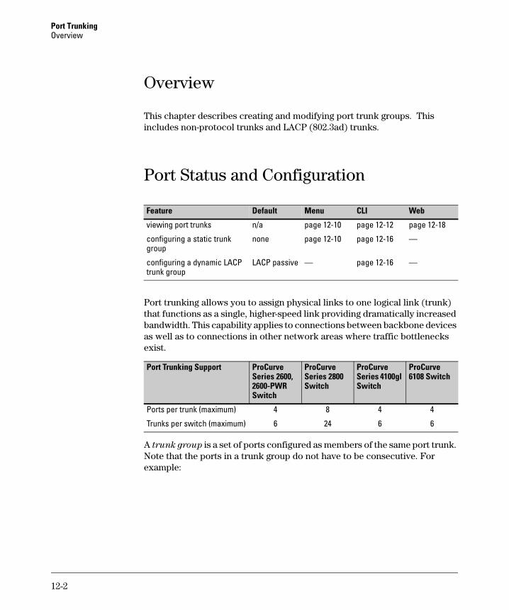
Port Trunking Overview
Overview
This chapter describes creating and modifying port trunk groups. This includes non-protocol trunks and LACP (802.3ad) trunks.
Port Status and Configuration
Feature Default Menu CLI Web
viewing port trunks n/a page 12-10 page 12-12 page 12-18
configuring a static trunk none page 12-10 page 12-16 — group
configuring a dynamic LACP LACP passive — page 12-16 — trunk group
Port trunking allows you to assign physical links to one logical link (trunk) that functions as a single, higher-speed link providing dramatically increased bandwidth. This capability applies to connections between backbone devices as well as to connections in other network areas where traffic bottlenecks exist.
Port Trunking Support ProCurve Series 2600, 2600-PWR Switch
ProCurve Series 2800 Switch
ProCurve Series 4100gl Switch
ProCurve 6108 Switch
Ports per trunk (maximum) 4 8 4 4
Trunks per switch (maximum) 6 24 6 6
A trunk group is a set of ports configured as members of the same port trunk. Note that the ports in a trunk group do not have to be consecutive. For example:
12-2
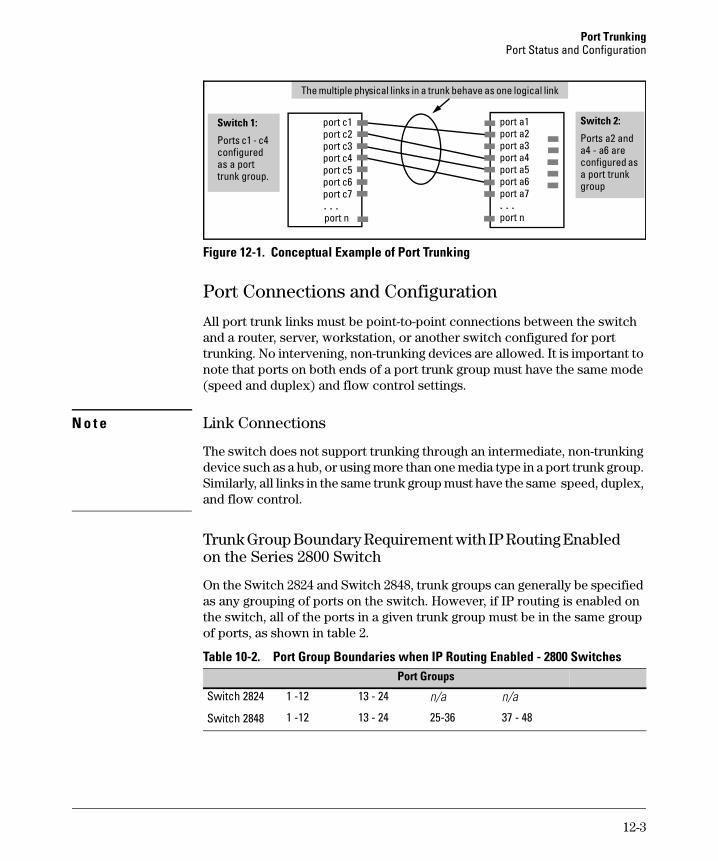
Port Trunking Port Status and Configuration
Switch 1:
l l
. . . . . .
Switch 2:
Ports c1 - c4 configured as a port trunk group.
The multiple physica links in a trunk behave as one logica link
port c1 port c2 port c3 port c4 port c5 port c6 port c7
port n
port a1 port a2 port a3 port a4 port a5 port a6 port a7
port n
Ports a2 and a4 - a6 are configured as a port trunk group
Figure 12-1. Conceptual Example of Port Trunking
Port Connections and Configuration
All port trunk links must be point-to-point connections between the switch and a router, server, workstation, or another switch configured for port trunking. No intervening, non-trunking devices are allowed. It is important to note that ports on both ends of a port trunk group must have the same mode (speed and duplex) and flow control settings.
N o t e Link Connections
The switch does not support trunking through an intermediate, non-trunking device such as a hub, or using more than one media type in a port trunk group. Similarly, all links in the same trunk group must have the same speed, duplex, and flow control.
Trunk Group Boundary Requirement with IP Routing Enabled on the Series 2800 Switch
On the Switch 2824 and Switch 2848, trunk groups can generally be specified as any grouping of ports on the switch. However, if IP routing is enabled on the switch, all of the ports in a given trunk group must be in the same group of ports, as shown in table 2.
Table 10-2. Port Group Boundaries when IP Routing Enabled - 2800 Switches Port Groups
Switch 2824 1 -12 13 - 24 n/a n/a
Switch 2848 1 -12 13 - 24 25-36 37 - 48
12-3
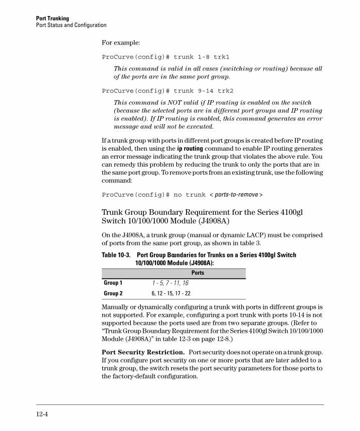
Port Trunking Port Status and Configuration
For example:
ProCurve(config)# trunk 1-8 trk1
This command is valid in all cases (switching or routing) because all
of the ports are in the same port group.
ProCurve(config)# trunk 9-14 trk2
This command is NOT valid if IP routing is enabled on the switch
(because the selected ports are in different port groups and IP routing
is enabled). If IP routing is enabled, this command generates an error
message and will not be executed.
If a trunk group with ports in different port groups is created before IP routing is enabled, then using the ip routing command to enable IP routing generates an error message indicating the trunk group that violates the above rule. You can remedy this problem by reducing the trunk to only the ports that are in the same port group. To remove ports from an existing trunk, use the following command:
ProCurve(config)# no trunk < ports-to-remove >
Trunk Group Boundary Requirement for the Series 4100gl Switch 10/100/1000 Module (J4908A)
On the J4908A, a trunk group (manual or dynamic LACP) must be comprised of ports from the same port group, as shown in table 3.
Table 10-3. Port Group Boundaries for Trunks on a Series 4100gl Switch 10/100/1000 Module (J4908A):
Ports
Group 1 1 - 5, 7 - 11, 16
Group 2 6, 12 - 15, 17 - 22
Manually or dynamically configuring a trunk with ports in different groups is not supported. For example, configuring a port trunk with ports 10-14 is not supported because the ports used are from two separate groups. (Refer to “Trunk Group Boundary Requirement for the Series 4100gl Switch 10/100/1000 Module (J4908A)” in table 12-3 on page 12-8.)
Port Security Restriction. Port security does not operate on a trunk group. If you configure port security on one or more ports that are later added to a trunk group, the switch resets the port security parameters for those ports to the factory-default configuration.
12-4
Port Trunking Port Status and Configuration
C a u t i o n To avoid broadcast storms or loops in your network while configuring a trunk, first disable or disconnect all ports you want to add to or remove from the trunk. After you configure the trunk, enable or re-connect the ports.
Port Trunk Options and Operation The switch offers these options for port trunking:
■ LACP (IEEE 802.3ad—page 12-18)
■ Trunk (non-protocol—page 12-25)
The switch supports six trunk groups of up to four ports each. (Using the Link Aggregation Control Protocol—LACP—option, you can include standby trunked ports in addition to the maximum of four actively trunking ports.)
L A C P N o t e LACP operation requires full-duplex (FDx) links. For most installations, HP recommends that you leave the port Mode settings at Auto (the default). LACP also operates with Auto-10, Auto-100, and Auto-1000 (if negotiation selects FDx); 10FDx, 100FDx, and 1000FDx settings.
Fault Tolerance: If a link in a port trunk fails, the switch redistributes traffic originally destined for that link to the remaining links in the trunk. The trunk remains operable as long as there is at least one link in operation. If a link is restored, that link is automatically included in the traffic distribution again. The LACP option also offers a standby link capability, which enables you to keep links in reserve for service if one or more of the original active links fails. See “Trunk Group Operation Using LACP” on page 12-18.)
Trunk Configuration Methods Dynamic LACP Trunk: The switch automatically negotiates trunked links between LACP-configured ports on separate devices, and offers one dynamic trunk option: LACP. To configure the switch to initiate a dynamic LACP trunk with another device, use the interface ethernet command in the CLI to set the default LACP option to Active on the ports you want to use for the trunk. For example, the following command configures ports C1-C4 to LACP active:
ProCurve(config) int c1-c4 lacp active
Note that the above example works if the ports are not already operating in a trunk. To change the LACP option on ports already operating as a trunk, you must first disable the trunked ports that you want to reconfigure. For example, if ports C1 - C4 were LACP-active and operating in a trunk with another device, you would do the following to change them to LACP-passive:
1. Go to the port context for ports c1 - c4 and disable these ports.
12-5
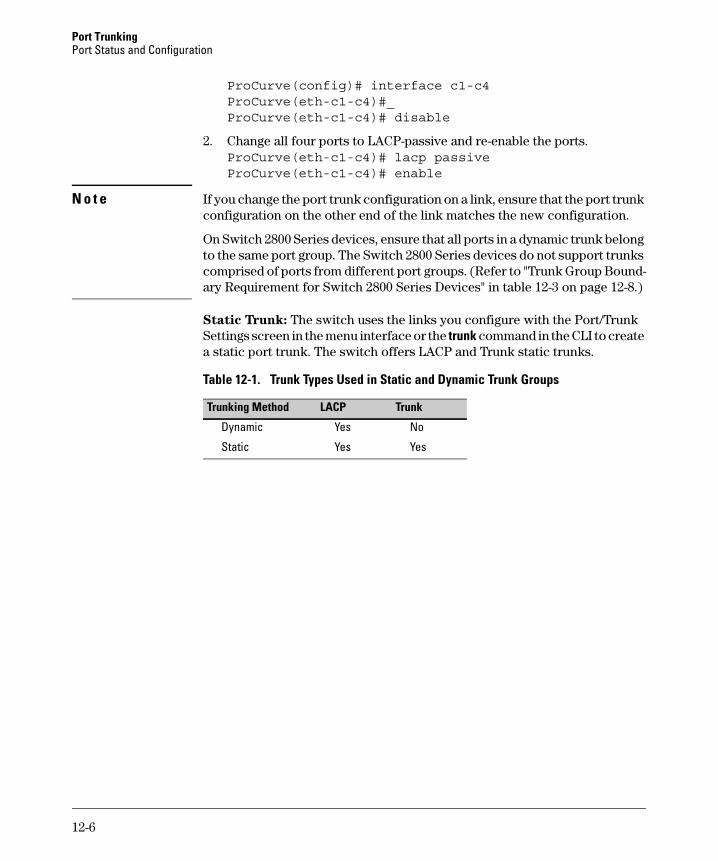
Port Trunking Port Status and Configuration
ProCurve(config)# interface c1-c4ProCurve(eth-c1-c4)#_ProCurve(eth-c1-c4)# disable
2. Change all four ports to LACP-passive and re-enable the ports. ProCurve(eth-c1-c4)# lacp passiveProCurve(eth-c1-c4)# enable
N o t e If you change the port trunk configuration on a link, ensure that the port trunk configuration on the other end of the link matches the new configuration.
On Switch 2800 Series devices, ensure that all ports in a dynamic trunk belong to the same port group. The Switch 2800 Series devices do not support trunks comprised of ports from different port groups. (Refer to "Trunk Group Boundary Requirement for Switch 2800 Series Devices" in table 12-3 on page 12-8.)
Static Trunk: The switch uses the links you configure with the Port/Trunk Settings screen in the menu interface or the trunk command in the CLI to create a static port trunk. The switch offers LACP and Trunk static trunks.
Table 12-1. Trunk Types Used in Static and Dynamic Trunk Groups
Trunking Method LACP Trunk
Dynamic Yes No
Static Yes Yes
12-6
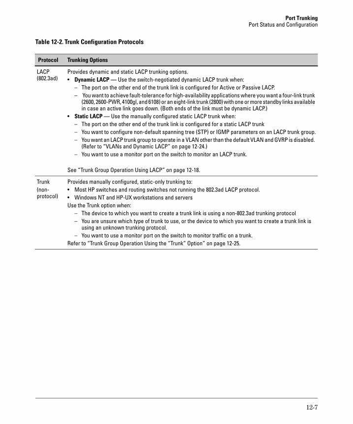
Port Trunking Port Status and Configuration
Table 12-2. Trunk Configuration Protocols
Protocol Trunking Options
LACP Provides dynamic and static LACP trunking options.(802.3ad) • Dynamic LACP — Use the switch-negotiated dynamic LACP trunk when:
– The port on the other end of the trunk link is configured for Active or Passive LACP. – You want to achieve fault-tolerance for high-availability applications where you want a four-link trunk
(2600, 2600-PWR, 4100gl, and 6108) or an eight-link trunk (2800) with one or more standby links available in case an active link goes down. (Both ends of the link must be dynamic LACP.)
• Static LACP — Use the manually configured static LACP trunk when: – The port on the other end of the trunk link is configured for a static LACP trunk – You want to configure non-default spanning tree (STP) or IGMP parameters on an LACP trunk group. – You want an LACP trunk group to operate in a VLAN other than the default VLAN and GVRP is disabled.
(Refer to “VLANs and Dynamic LACP” on page 12-24.) – You want to use a monitor port on the switch to monitor an LACP trunk.
See “Trunk Group Operation Using LACP” on page 12-18.
Trunk Provides manually configured, static-only trunking to:(non- • Most HP switches and routing switches not running the 802.3ad LACP protocol.protocol) • Windows NT and HP-UX workstations and servers
Use the Trunk option when: – The device to which you want to create a trunk link is using a non-802.3ad trunking protocol – You are unsure which type of trunk to use, or the device to which you want to create a trunk link is
using an unknown trunking protocol. – You want to use a monitor port on the switch to monitor traffic on a trunk.
Refer to “Trunk Group Operation Using the “Trunk” Option” on page 12-25.
12-7
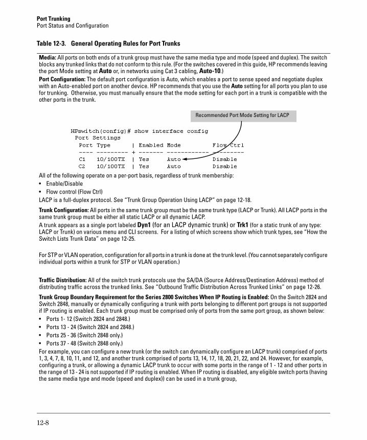
Port Trunking Port Status and Configuration
Table 12-3. General Operating Rules for Port Trunks
Media: All ports on both ends of a trunk group must have the same media type and mode (speed and duplex). The switch blocks any trunked links that do not conform to this rule. (For the switches covered in this guide, HP recommends leaving the port Mode setting at Auto or, in networks using Cat 3 cabling, Auto-10.) Port Configuration: The default port configuration is Auto, which enables a port to sense speed and negotiate duplex with an Auto-enabled port on another device. HP recommends that you use the Auto setting for all ports you plan to use for trunking. Otherwise, you must manually ensure that the mode setting for each port in a trunk is compatible with the other ports in the trunk.
Recommended Port Mode Setting for LACP
All of the following operate on a per-port basis, regardless of trunk membership: • Enable/Disable • Flow control (Flow Ctrl)LACP is a full-duplex protocol. See “Trunk Group Operation Using LACP” on page 12-18.
Trunk Configuration: All ports in the same trunk group must be the same trunk type (LACP or Trunk). All LACP ports in the same trunk group must be either all static LACP or all dynamic LACP.A trunk appears as a single port labeled Dyn1 (for an LACP dynamic trunk) or Trk1 (for a static trunk of any type: LACP or Trunk) on various menu and CLI screens. For a listing of which screens show which trunk types, see “How theSwitch Lists Trunk Data” on page 12-25.
For STP or VLAN operation, configuration for all ports in a trunk is done at the trunk level. (You cannot separately configureindividual ports within a trunk for STP or VLAN operation.)
Traffic Distribution: All of the switch trunk protocols use the SA/DA (Source Address/Destination Address) method of distributing traffic across the trunked links. See “Outbound Traffic Distribution Across Trunked Links” on page 12-26.
Trunk Group Boundary Requirement for the Series 2800 Switches When IP Routing is Enabled: On the Switch 2824 andSwitch 2848, manually or dynamically configuring a trunk with ports belonging to different port groups is not supportedif IP routing is enabled. Each trunk group must be comprised only of ports from the same port group, as shown below:• Ports 1- 12 (Switch 2824 and 2848.)• Ports 13 - 24 (Switch 2824 and 2848.)• Ports 25 - 36 (Switch 2848 only.)• Ports 37 - 48 (Switch 2848 only.)For example, you can configure a new trunk (or the switch can dynamically configure an LACP trunk) comprised of ports 1, 3, 4, 7, 8, 10, 11, and 12, and another trunk comprised of ports 13, 14, 17, 18, 20, 21, 22, and 24. However, for example, configuring a trunk, or allowing a dynamic LACP trunk to occur with some ports in the range of 1 - 12 and other ports in the range of 13 - 24 is not supported if IP routing is enabled. When IP routing is disabled, any eligible switch ports (havingthe same media type and mode (speed and duplex)) can be used in a trunk group,
12-8
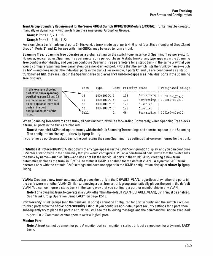
Port Trunking Port Status and Configuration
Trunk Group Boundary Requirement for the Series 4100gl Switch 10/100/1000 Module (J4908A): Trunks must be created, manually or dynamically, with ports from the same group, Group1 or Group2.
Group1: Ports 1-5, 7-11, 16 Group2: Ports 6, 12-15, 17-22
For example, a trunk made up of ports 3 - 5 is valid; a trunk made up of ports 4 - 6 is not (port 6 is a member of Group2, not Group 1. Ports 21 and 22, for use with mini-GBICs, may be used to form a trunk.
Spanning Tree: Spanning Tree operates as a global setting on the switch (one instance of Spanning Tree per switch). However, you can adjust Spanning Tree parameters on a per-port basis. A static trunk of any type appears in the Spanning Tree configuration display, and you can configure Spanning Tree parameters for a static trunk in the same way that you would configure Spanning Tree parameters on a non-trunked port. (Note that the switch lists the trunk by name—such as Trk1—and does not list the individual ports in the trunk.) For example, if ports C1 and C2 are configured as a static trunk named Trk1, they are listed in the Spanning Tree display as Trk1 and do not appear as individual ports in the Spanning Tree displays.
l
i
In this examp e showing part of the show spanning-tree listing, ports C1 and C2 are members of TRK1 and do not appear as ind vidual ports in the port configuration part of the listing.
When Spanning Tree forwards on a trunk, all ports in the trunk will be forwarding. Conversely, when Spanning Tree blocks a trunk, all ports in the trunk are blocked.
Note: A dynamic LACP trunk operates only with the default Spanning Tree settings and does not appear in the Spanning Tree configuration display or show ip igmp listing.
If you remove a port from a static trunk, the port retains the same Spanning Tree settings that were configured for the trunk.
IP Multicast Protocol (IGMP): A static trunk of any type appears in the IGMP configuration display, and you can configure IGMP for a static trunk in the same way that you would configure IGMP on a non-trunked port. (Note that the switch lists the trunk by name—such as Trk1—and does not list the individual ports in the trunk.) Also, creating a new trunk automatically places the trunk in IGMP Auto status if IGMP is enabled for the default VLAN. A dynamic LACP trunk operates only with the default IGMP settings and does not appear in the IGMP configuration display or show ip igmp listing.
VLANs: Creating a new trunk automatically places the trunk in the DEFAULT_VLAN, regardless of whether the ports in the trunk were in another VLAN. Similarly, removing a port from a trunk group automatically places the port in the default VLAN. You can configure a static trunk in the same way that you configure a port for membership in any VLAN.
Note: For a dynamic trunk to operate in a VLAN other than the default VLAN (DEFAULT_VLAN), GVRP must be enabled. See “Trunk Group Operation Using LACP” on page 12-18.
Port Security: Trunk groups (and their individual ports) cannot be configured for port security, and the switch excludes trunked ports from the show port-security listing. If you configure non-default port security settings for a port, then subsequently try to place the port in a trunk, you will see the following message and the command will not be executed:
< port-list > Command cannot operate over a logical port.
Monitor Port: Note: A trunk cannot be a monitor port. A monitor port can monitor a static trunk but cannot monitor a dynamic LACP trunk.
12-9
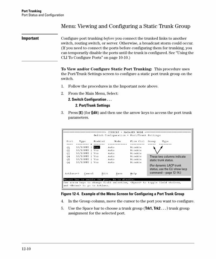
Port Trunking Port Status and Configuration
Menu: Viewing and Configuring a Static Trunk Group
Important Configure port trunking before you connect the trunked links to another switch, routing switch, or server. Otherwise, a broadcast storm could occur. (If you need to connect the ports before configuring them for trunking, you can temporarily disable the ports until the trunk is configured. See “Using the CLI To Configure Ports” on page 10-10.)
To View and/or Configure Static Port Trunking: This procedure uses the Port/Trunk Settings screen to configure a static port trunk group on the switch.
1. Follow the procedures in the Important note above.
2. From the Main Menu, Select:
2. Switch Configuration . . . 2. Port/Trunk Settings
3. Press [E] (for Edit) and then use the arrow keys to access the port trunk parameters.
These two columns indicate static trunk status.
(For dynamic LACP trunk status, use the CLI show lacp command—page 12-14.)
Figure 12-4. Example of the Menu Screen for Configuring a Port Trunk Group
4. In the Group column, move the cursor to the port you want to configure.
5. Use the Space bar to choose a trunk group (Trk1, Trk2 . . . ) trunk group assignment for the selected port.
12-10
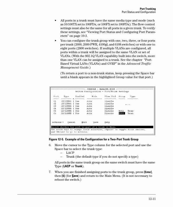
Port Trunking Port Status and Configuration
• All ports in a trunk must have the same media type and mode (such as 10/100TX set to 100FDx, or 100FX set to 100FDx). The flow control settings must also be the same for all ports in a given trunk. To verify these settings, see “Viewing Port Status and Configuring Port Parameters” on page 10-3.
• You can configure the trunk group with one, two, three, or four ports per trunk (2600, 2600-PWR, 4100gl, and 6108 switches) or with one to eight ports (2800 switches). If multiple VLANs are configured, all ports within a trunk will be assigned to the same VLAN or set of VLANs. (With the 802.1Q VLAN capability built into the switch, more than one VLAN can be assigned to a trunk. See the chapter “Port-Based Virtual LANs (VLANs) and GVRP” in the Advanced Traffic
Management Guide.)
(To return a port to a non-trunk status, keep pressing the Space bar until a blank appears in the highlighted Group value for that port.)
Figure 12-5. Example of the Configuration for a Two-Port Trunk Group
6. Move the cursor to the Type column for the selected port and use the Space bar to select the trunk type:
– LACP – Trunk (the default type if you do not specify a type)
All ports in the same trunk group on the same switch must have the same Type (LACP or Trunk).
7. When you are finished assigning ports to the trunk group, press [Enter], then [S] (for Save) and return to the Main Menu. (It is not necessary to reboot the switch.)
12-11
Port Trunking Port Status and Configuration
During the Save process, traffic on the ports configured for trunking will be delayed for several seconds. If the Spanning Tree Protocol is enabled, the delay may be up to 30 seconds.
8. Connect the trunked ports on the switch to the corresponding ports on the opposite device. If you previously disabled any of the trunked ports on the switch, enable them now. (See “Viewing Port Status and Configuring Port Parameters” on page 10-3.)
Check the Event Log (“Using Logging To Identify Problem Sources” on page C-23) to verify that the trunked ports are operating properly.
CLI: Viewing and Configuring a Static or Dynamic Port Trunk Group
Trunk Status and Configuration Commands
show trunks below
show lacp page 12-14
trunk page 12-16
interface lacp page 12-16
Using the CLI To View Port Trunks
You can list the trunk type and group for all ports on the switch or for selected ports. You can also list LACP-only status information for LACP-configured ports.
Listing Static Trunk Type and Group for All Ports or Selected Ports.
Syntax: show trunks [<port-list>]
Omitting the < port-list > parameter results in a static trunk data listing for all LAN ports in the switch. For example, in a switch where ports A4 and A5 belong to Trunk 1 and ports A7 and A8 belong to Trunk 2, you have the options shown in figures 12-6 and 12-7 for displaying port data for ports belonging to static trunks.
12-12
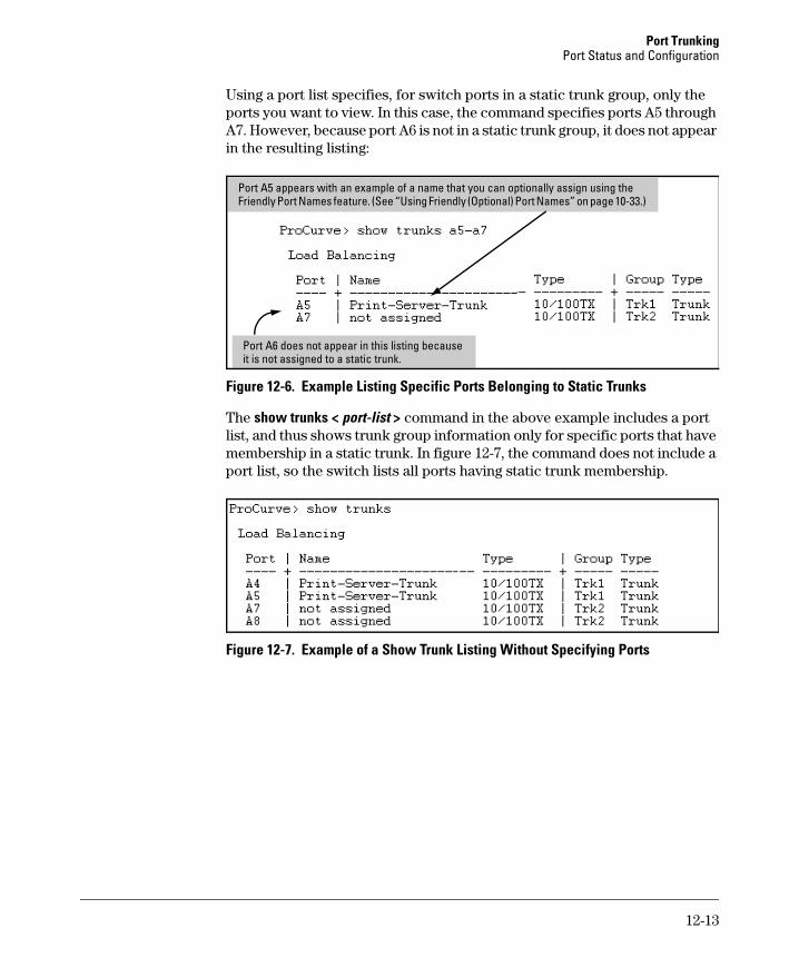
Port Trunking Port Status and Configuration
Using a port list specifies, for switch ports in a static trunk group, only the ports you want to view. In this case, the command specifies ports A5 through A7. However, because port A6 is not in a static trunk group, it does not appear in the resulting listing:
lii
Port A5 appears with an example of a name that you can optionally assign using the Friendly Port Names feature. (See “Using Friendly (Optional) Port Names” on page 10-33.)
Port A6 does not appear in this sting because t is not assigned to a static trunk.
Figure 12-6. Example Listing Specific Ports Belonging to Static Trunks
The show trunks < port-list > command in the above example includes a port list, and thus shows trunk group information only for specific ports that have membership in a static trunk. In figure 12-7, the command does not include a port list, so the switch lists all ports having static trunk membership.
Figure 12-7. Example of a Show Trunk Listing Without Specifying Ports
12-13
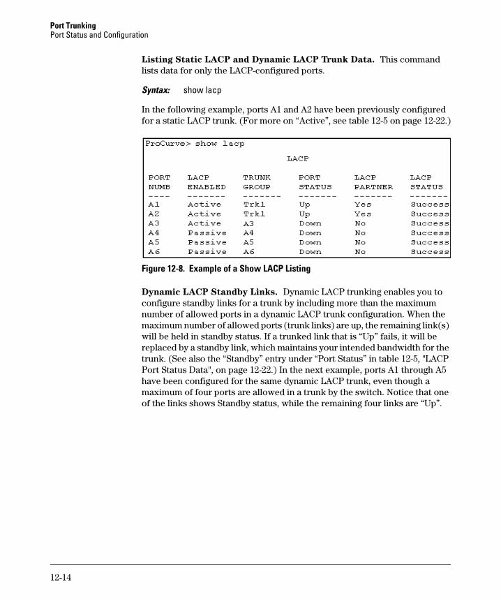
Port Trunking Port Status and Configuration
Listing Static LACP and Dynamic LACP Trunk Data. This command lists data for only the LACP-configured ports.
Syntax: show lacp
In the following example, ports A1 and A2 have been previously configured for a static LACP trunk. (For more on “Active”, see table 12-5 on page 12-22.)
Figure 12-8. Example of a Show LACP Listing
Dynamic LACP Standby Links. Dynamic LACP trunking enables you to configure standby links for a trunk by including more than the maximum number of allowed ports in a dynamic LACP trunk configuration. When the maximum number of allowed ports (trunk links) are up, the remaining link(s) will be held in standby status. If a trunked link that is “Up” fails, it will be replaced by a standby link, which maintains your intended bandwidth for the trunk. (See also the “Standby” entry under “Port Status” in table 12-5, "LACP Port Status Data", on page 12-22.) In the next example, ports A1 through A5 have been configured for the same dynamic LACP trunk, even though a maximum of four ports are allowed in a trunk by the switch. Notice that one of the links shows Standby status, while the remaining four links are “Up”.
12-14
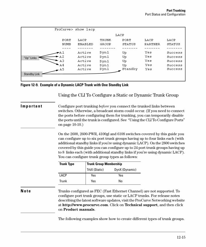
Port Trunking Port Status and Configuration
“Up” Links
Standby Link
Figure 12-9. Example of a Dynamic LACP Trunk with One Standby Link
Using the CLI To Configure a Static or Dynamic Trunk Group
I m p o r t a n t Configure port trunking before you connect the trunked links between switches. Otherwise, a broadcast storm could occur. (If you need to connect the ports before configuring them for trunking, you can temporarily disable the ports until the trunk is configured. See “Using the CLI To Configure Ports” on page 10-10.)
On the 2600, 2600-PWR, 4100gl and 6108 switches covered by this guide you can configure up to six port trunk groups having up to four links each (with additional standby links if you’re using dynamic LACP). On the 2800 switches covered by this guide you can configure up to 24 port trunk groups having up to 8 links each (with additional standby links if you’re using dynamic LACP). You can configure trunk group types as follows:
Trunk Type Trunk Group Membership
TrkX (Static) DynX (Dynamic)
LACP Yes Yes
Trunk Yes No
N o t e Trunks configured as FEC (Fast Ethernet Channel) are not supported. To configure port trunk groups, use static or LACP trunks. For release notes describing the latest software updates, visit the ProCurve Networking website at http://www.procurve.com. Click on Technical support, and then click on Product manuals.
The following examples show how to create different types of trunk groups.
12-15
Port Trunking Port Status and Configuration
Configuring a Static Trunk or Static LACP Trunk Group.
For 2600, 2600-PWR, 4100gl, and 6108 switches:
Syntax: trunk <port-list> < trk1 | trk2 | trk3 | trk4 | trk5 | trk6 > < trunk | lacp >
For 2800 switches:
Syntax: trunk <port-list> < trk1 ... trk24 > < trunk | lacp >
The following example uses ports C4 - C6 to create a non-protocol static trunk group with the group name of Trk2.
ProCurve(config)# trunk c4-c6 trk2 trunk
Removing Ports from a Static Trunk Group. This command removes one or more ports from an existing Trkx trunk group.
C a u t i o n Removing a port from a trunk can result in a loop and cause a broadcast storm. When you remove a port from a trunk where STP is not in use, HP recommends that you first disable the port or disconnect the link on that port.
Syntax: no trunk < port-list >
This example removes ports C4 and C5 from an existing trunk group.
ProCurve(config)# no trunk c4-c5
Enabling a Dynamic LACP Trunk Group. In the default port configuration, all ports on the switch are set to LACP Passive. However, to enable the switch to automatically form a trunk group that is dynamic on both ends of the link, the ports on one end of a set of links must be LACP Active. The ports on the other end can be either LACP Active or LACP Passive. This command enables the switch to automatically establish a dynamic LACP trunk group when the device ports on the other end of the link are configured for LACP Passive.
12-16
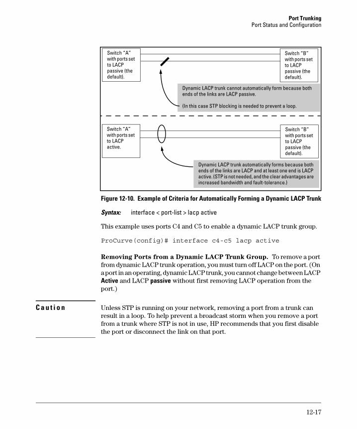
Port Trunking Port Status and Configuration
passive (the default).
i
with ports set with ports set
passive (the default).
i
)
Switch “A” with ports set to LACP passive (the default).
Switch “B” with ports set to LACP
Dynamic LACP trunk cannot automatically form because both ends of the l nks are LACP passive.
(In this case STP blocking is needed to prevent a loop.
Switch “A”
to LACP active.
Switch “B”
to LACP
Dynamic LACP trunk automatically forms because both ends of the links are LACP and at least one end s LACP active. (STP is not needed, and the clear advantages are increased bandwidth and fault-tolerance.
Figure 12-10. Example of Criteria for Automatically Forming a Dynamic LACP Trunk
Syntax: interface < port-list > lacp active
This example uses ports C4 and C5 to enable a dynamic LACP trunk group.
ProCurve(config)# interface c4-c5 lacp active
Removing Ports from a Dynamic LACP Trunk Group. To remove a port from dynamic LACP trunk operation, you must turn off LACP on the port. (On a port in an operating, dynamic LACP trunk, you cannot change between LACP Active and LACP passive without first removing LACP operation from the port.)
C a u t i o n Unless STP is running on your network, removing a port from a trunk can result in a loop. To help prevent a broadcast storm when you remove a port from a trunk where STP is not in use, HP recommends that you first disable the port or disconnect the link on that port.
12-17
Port Trunking Port Status and Configuration
Syntax: no interface <port-list> lacp
In this example, port C6 belongs to an operating, dynamic LACP trunk. To remove port C6 from the dynamic trunk and return it to passive LACP, you would do the following:
ProCurve>(config)# no interface c6 lacpProCurve>(config)# interface c6 lacp passive
Note that in the above example, if the port on the other end of the link is configured for active LACP or static LACP, the trunked link will be reestablished almost immediately.
Web: Viewing Existing Port Trunk Groups
While the web browser interface does not enable you to configure a port trunk group, it does provide a view of an existing trunk group.
To view any port trunk groups:
Click on the Status tab.
Click on Port Status.
Trunk Group Operation Using LACP
The switch can automatically configure a dynamic LACP trunk group or you can manually configure a static LACP trunk group.
N o t e LACP requires full-duplex (FDx) links of the same media type (10/100Base-T, 100FX, etc.) and the same speed, and enforces speed and duplex conformance across a trunk group.
LACP trunk status commands include:
Trunk Display Method Static LACP Trunk Dynamic LACP Trunk
CLI show lacp command Included in listing. Included in listing.
CLI show trunk command Included in listing. Not included.
Port/Trunk Settings screen in menu interface Included in listing. Not included
Thus, to display a listing of dynamic LACP trunk ports, you must use the show lacp command.
12-18
Port Trunking Port Status and Configuration
N o t e Dynamic LACP trunks operate only in the default VLAN (unless GVRP is enabled and Forbid is used to prevent the trunked ports from joining the default VLAN). Thus, if an LACP dynamic trunk forms using ports that are not in the default VLAN, the trunk will automatically move to the default VLAN unless GVRP operation is configured to prevent this from occurring. In some cases, this can create a traffic loop in your network. For more on this topic, refer to “VLANs and Dynamic LACP” on page 12-24.
In most cases, trunks configured for LACP operate as described in table 12-4 on the next page.
12-19
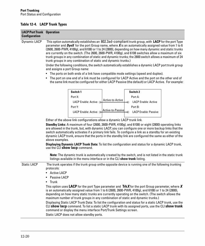
Port Trunking Port Status and Configuration
Table 12-4. LACP Trunk Types
Configuration LACP Port Trunk Operation
Dynamic LACP This option automatically establishes an 802.3ad-compliant trunk group, with LACP for the port Type parameter and DynX for the port Group name, where X is an automatically assigned value from 1 to 6 (2600, 2600-PWR, 4100gl, and 6108) or 1 to 24 (2800), depending on how many dynamic and static trunks are currently on the switch. (The 2600, 2600-PWR, 4100gl, and 6108 switches allow a maximum of six trunk groups in any combination of static and dynamic trunks; the 2800 switch allows a maximum of 24 trunk groups in any combination of static and dynamic trunks.) Under the following conditions, the switch automatically establishes a dynamic LACP port trunk group and assigns a port Group name: • The ports on both ends of a link have compatible mode settings (speed and duplex). • The port on one end of a link must be configured for LACP Active and the port on the other end of
the same link must be configured for either LACP Passive (the default) or LACP Active. For example:
Port X:
l
Port Y:
l
Switch 2
:
:
le: ii i
Switch 1
LACP Enab e: Active
LACP Enab e: Active
Port A
LACP Enable: Active
Port B
LACP Enab Pass ve
Active-to-Active
Act ve-to-Pass ve
Either of the above link configurations allow a dynamic LACP trunk link.Standby Links: A maximum of four (2600, 2600-PWR, 4100gl, and 6108) or eight (2800) operating links are allowed in the trunk, but, with dynamic LACP, you can configure one or more backup links that the switch automatically activates if a primary link fails. To configure a link as a standby for an existing dynamic LACP trunk, ensure that the ports in the standby link are configured the same as either of the above examples.Displaying Dynamic LACP Trunk Data: To list the configuration and status for a dynamic LACP trunk, use the CLI show lacp command.
Note: The dynamic trunk is automatically created by the switch, and is not listed in the static trunk listings available in the menu interface or in the CLI show trunk listing.
Static LACP The trunk operates if the trunk group on the opposite device is running one of the following trunking protocols: • Active LACP • Passive LACP • Trunk This option uses LACP for the port Type parameter and TrkX for the port Group parameter, where X is an automatically assigned value from 1 to 6 (2600, 2600-PWR, 4100gl, and 6108) or 1 to 24 (2800), depending on how many static trunks are currently operating on the switch. (The switch allows the maximum number of trunk groups in any combination of static and dynamic trunks.)Displaying Static LACP Trunk Data: To list the configuration and status for a static LACP trunk, use the CLI show lacp command. To list a static LACP trunk with its assigned ports, use the CLI show trunkcommand or display the menu interface Port/Trunk Settings screen.Static LACP does not allow standby ports.
12-20
Port Trunking Port Status and Configuration
Default Port Operation
In the default configuration, all ports are configured for passive LACP. However, if LACP is not configured, the port will not try to detect a trunk configuration and will operate as a standard, untrunked port.
N o t e Passive and active LACP port will pause and listen for LACP packets once a link is established. Once this pause is complete then the port, if a trunk is not detected, will be placed in forwarding mode. Some end-node applications have been found to be sensitive to this pause and may require LACP to be disabled on the port.
The following table describes the elements of per-port LACP operation. To display this data for a particular switch, execute the following command in the CLI:
ProCurve> show lacp
12-21
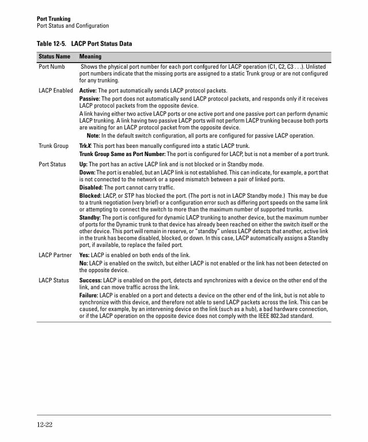
Port Trunking Port Status and Configuration
Table 12-5. LACP Port Status Data
Status Name Meaning
Port Numb Shows the physical port number for each port configured for LACP operation (C1, C2, C3 . . .). Unlisted port numbers indicate that the missing ports are assigned to a static Trunk group or are not configured for any trunking.
LACP Enabled Active: The port automatically sends LACP protocol packets. Passive: The port does not automatically send LACP protocol packets, and responds only if it receives LACP protocol packets from the opposite device.A link having either two active LACP ports or one active port and one passive port can perform dynamic LACP trunking. A link having two passive LACP ports will not perform LACP trunking because both ports are waiting for an LACP protocol packet from the opposite device.
Note: In the default switch configuration, all ports are configured for passive LACP operation.
Trunk Group TrkX: This port has been manually configured into a static LACP trunk. Trunk Group Same as Port Number: The port is configured for LACP, but is not a member of a port trunk.
Port Status Up: The port has an active LACP link and is not blocked or in Standby mode. Down: The port is enabled, but an LACP link is not established. This can indicate, for example, a port that is not connected to the network or a speed mismatch between a pair of linked ports.Disabled: The port cannot carry traffic.Blocked: LACP, or STP has blocked the port. (The port is not in LACP Standby mode.) This may be due to a trunk negotiation (very brief) or a configuration error such as differing port speeds on the same link or attempting to connect the switch to more than the maximum number of supported trunks. Standby: The port is configured for dynamic LACP trunking to another device, but the maximum number of ports for the Dynamic trunk to that device has already been reached on either the switch itself or the other device. This port will remain in reserve, or “standby” unless LACP detects that another, active link in the trunk has become disabled, blocked, or down. In this case, LACP automatically assigns a Standby port, if available, to replace the failed port.
LACP Partner Yes: LACP is enabled on both ends of the link. No: LACP is enabled on the switch, but either LACP is not enabled or the link has not been detected on the opposite device.
LACP Status Success: LACP is enabled on the port, detects and synchronizes with a device on the other end of the link, and can move traffic across the link.Failure: LACP is enabled on a port and detects a device on the other end of the link, but is not able to synchronize with this device, and therefore not able to send LACP packets across the link. This can be caused, for example, by an intervening device on the link (such as a hub), a bad hardware connection, or if the LACP operation on the opposite device does not comply with the IEEE 802.3ad standard.
12-22
Port Trunking Port Status and Configuration
LACP Notes and Restrictions
802.1X (Port-Based Access Control) Configured on a Port. To maintain security, LACP is not allowed on ports configured for 802.1X authenticator operation. If you configure port security on a port on which LACP (active or passive) is configured, the switch removes the LACP configuration, displays a notice that LACP is disabled on the port(s), and enables 802.1X on that port.
ProCurve(config)# aaa port-access authenticator e b1LACP has been disabled on 802.1X port(s).
The switch will not allow you to configure LACP on a port on which port access (802.1X) is enabled. For example:
ProCurve(config)# int b1 lacp passiveError configuring port < port-number >: LACP and 802.1X cannot be runtogether.
To restore LACP to the port, you must first remove the port’s 802.1X configuration and then re-enable LACP active or passive on the port.
Port Security Configured on a Port. To maintain security, LACP is not allowed on ports configured for port security. If you configure port security on a port on which LACP (active or passive) is configured, the switch removes the LACP configuration, displays a notice that LACP is disabled on the port(s), and enables port security on that port. For example:
ProCurve(config)# port-security a17 learn-mode static address-limit 2LACP has been disabled on secured port(s).
The switch will not allow you to configure LACP on a port on which port security is enabled. For example:
ProCurve(config)# int a17 lacp passiveError configuring port A17: LACP and port security cannot be run together.
To restore LACP to the port, you must remove port security and re-enable LACP active or passive.
Changing Trunking Methods. To convert a trunk from static to dynamic, you must first eliminate the static trunk.
12-23
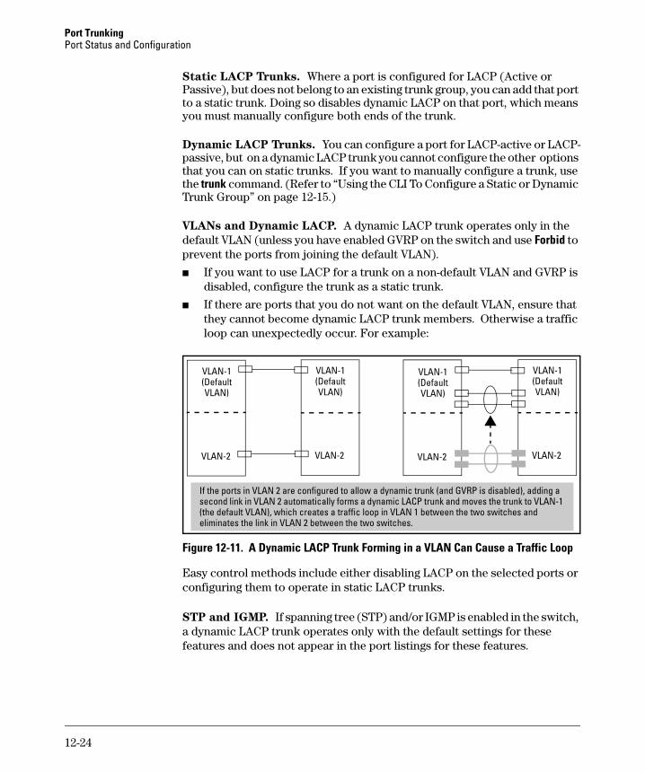
Port Trunking Port Status and Configuration
Static LACP Trunks. Where a port is configured for LACP (Active or Passive), but does not belong to an existing trunk group, you can add that port to a static trunk. Doing so disables dynamic LACP on that port, which means you must manually configure both ends of the trunk.
Dynamic LACP Trunks. You can configure a port for LACP-active or LACP-passive, but on a dynamic LACP trunk you cannot configure the other options that you can on static trunks. If you want to manually configure a trunk, use the trunk command. (Refer to “Using the CLI To Configure a Static or Dynamic Trunk Group” on page 12-15.)
VLANs and Dynamic LACP. A dynamic LACP trunk operates only in the default VLAN (unless you have enabled GVRP on the switch and use Forbid to prevent the ports from joining the default VLAN).
■ If you want to use LACP for a trunk on a non-default VLAN and GVRP is disabled, configure the trunk as a static trunk.
■ If there are ports that you do not want on the default VLAN, ensure that they cannot become dynamic LACP trunk members. Otherwise a traffic loop can unexpectedly occur. For example:
(Default
VLAN-2
VLAN) (Default
VLAN-2
(Default
VLAN-2
ll isabl
VLAN-1
VLAN)
VLAN-1 (Default
VLAN-2
VLAN-1
VLAN)
VLAN-1
VLAN)
If the ports in VLAN 2 are configured to a ow a dynamic trunk (and GVRP is d ed), adding a second link in VLAN 2 automatically forms a dynamic LACP trunk and moves the trunk to VLAN-1 (the default VLAN), which creates a traffic loop in VLAN 1 between the two switches and eliminates the link in VLAN 2 between the two switches.
Figure 12-11. A Dynamic LACP Trunk Forming in a VLAN Can Cause a Traffic Loop
Easy control methods include either disabling LACP on the selected ports or configuring them to operate in static LACP trunks.
STP and IGMP. If spanning tree (STP) and/or IGMP is enabled in the switch, a dynamic LACP trunk operates only with the default settings for these features and does not appear in the port listings for these features.
12-24
Port Trunking Port Status and Configuration
Half-Duplex and/or Different Port Speeds Not Allowed in LACP
Trunks. The ports on both sides of an LACP trunk must be configured for the same speed and for full-duplex (FDx). The 802.3ad LACP standard specifies a full-duplex (FDx) requirement for LACP trunking.
A port configured as LACP passive and not assigned to a port trunk can be configured to half-duplex (HDx). However, in any of the following cases, a port cannot be reconfigured to an HDx setting:
■ If a port is set to LACP Active, you cannot configure it to HDx.
■ If a port is already a member of a static or dynamic LACP trunk, you cannot configure it to HDx.
■ If a port is already set to HDx, the switch does not allow you to configure it for a static or dynamic LACP trunk.
Dynamic/Static LACP Interoperation: A port configured for dynamic LACP can properly interoperate with a port configured for static (TrkX) LACP, but any ports configured as standby LACP links will be ignored.
Trunk Group Operation Using the “Trunk” Option
This method creates a trunk group that operates independently of specific trunking protocols and does not use a protocol exchange with the device on the other end of the trunk. With this choice, the switch simply uses the SA/DA method of distributing outbound traffic across the trunked ports without regard for how that traffic is handled by the device at the other end of the trunked links. Similarly, the switch handles incoming traffic from the trunked links as if it were from a trunked source.
Use the Trunk option when you are trying to establish a trunk group between the switch and another device, but the other device’s trunking operation fails to interoperate properly with LACP trunking configured on the switch itself.
How the Switch Lists Trunk Data
Static Trunk Group: Appears in the menu interface and the output from the CLI show trunk and show interfaces commands.
Dynamic LACP Trunk Group: Appears in the output from the CLI show lacp command.
12-25
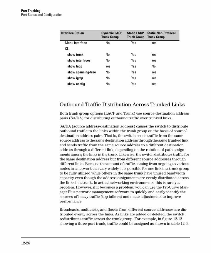
Port Trunking Port Status and Configuration
Interface Option Dynamic LACP Static LACP Trunk Group Trunk Group
Static Non-Protocol Trunk Group
Menu Interface No Yes Yes
CLI:
show trunk No Yes Yes
show interfaces No Yes Yes
show lacp Yes Yes No
show spanning-tree No Yes Yes
show igmp No Yes Yes
show config No Yes Yes
Outbound Traffic Distribution Across Trunked Links
Both trunk group options (LACP and Trunk) use source-destination address pairs (SA/DA) for distributing outbound traffic over trunked links.
SA/DA (source address/destination address) causes the switch to distribute outbound traffic to the links within the trunk group on the basis of source/ destination address pairs. That is, the switch sends traffic from the same source address to the same destination address through the same trunked link, and sends traffic from the same source address to a different destination address through a different link, depending on the rotation of path assignments among the links in the trunk. Likewise, the switch distributes traffic for the same destination address but from different source addresses through different links. Because the amount of traffic coming from or going to various nodes in a network can vary widely, it is possible for one link in a trunk group to be fully utilized while others in the same trunk have unused bandwidth capacity even though the address assignments are evenly distributed across the links in a trunk. In actual networking environments, this is rarely a problem. However, if it becomes a problem, you can use the ProCurve Manager Plus network management software to quickly and easily identify the sources of heavy traffic (top talkers) and make adjustments to improve performance.
Broadcasts, multicasts, and floods from different source addresses are distributed evenly across the links. As links are added or deleted, the switch redistributes traffic across the trunk group. For example, in figure 12-12 showing a three-port trunk, traffic could be assigned as shown in table 12-6.
12-26
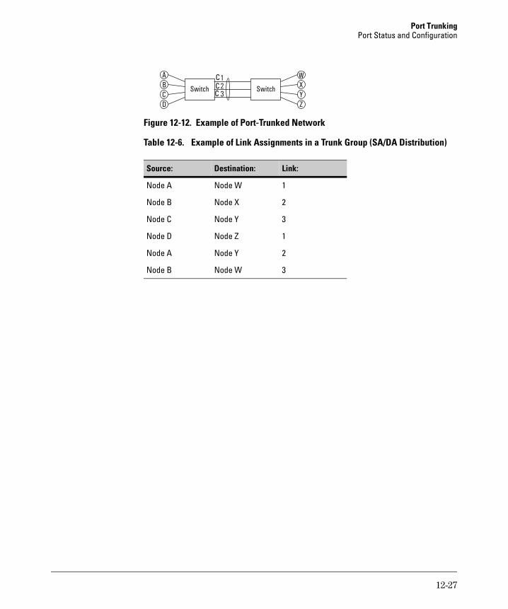
Port Trunking Port Status and Configuration
A W
C Y
B X
D Z
1
2
3
C C CSwitch Switch
Figure 12-12. Example of Port-Trunked Network
Table 12-6. Example of Link Assignments in a Trunk Group (SA/DA Distribution)
Source: Destination: Link:
1Node A Node W
Node B Node X 2
Node C Node Y 3
Node D Node Z 1
Node A Node Y 2
Node B Node W 3
12-27

Port Trunking Port Status and Configuration
— This page is intentionally unused. —
12-28

13
Configuring for Network Management Applications
Contents Using SNMP Tools To Manage the Switch . . . . . . . . . . . . . . . . . . . . . . . . . 13-3
Overview . . . . . . . . . . . . . . . . . . . . . . . . . . . . . . . . . . . . . . . . . . . . . . . . . . 13-3
SNMP Management Features . . . . . . . . . . . . . . . . . . . . . . . . . . . . . . . . . 13-4
Configuring for SNMP Access to the Switch . . . . . . . . . . . . . . . . . . . . 13-4
Configuring for SNMP Version 3 Access to the Switch . . . . . . . . . . . 13-5
SNMP Version 3 Commands . . . . . . . . . . . . . . . . . . . . . . . . . . . . . . . . . 13-6SNMPv3 Enable . . . . . . . . . . . . . . . . . . . . . . . . . . . . . . . . . . . . . . . . 13-7
SNMP Version 3 Users . . . . . . . . . . . . . . . . . . . . . . . . . . . . . . . . . . . . . . 13-8Group Access Levels . . . . . . . . . . . . . . . . . . . . . . . . . . . . . . . . . . . 13-11
SNMP Communities . . . . . . . . . . . . . . . . . . . . . . . . . . . . . . . . . . . . . . . 13-12Menu: Viewing and Configuring non-SNMP version 3 Communities . . . . . . . . . . . . . . . . . . . . . . . . . . . . . . . . . . . . . . . . . . 13-14CLI: Viewing and Configuring SNMP Community Names . . . . 13-16
SNMP Notification and Traps . . . . . . . . . . . . . . . . . . . . . . . . . . . . . . . 13-18Trap Features . . . . . . . . . . . . . . . . . . . . . . . . . . . . . . . . . . . . . . . . . 13-20Using the CLI To Enable Authentication Traps . . . . . . . . . . . . . 13-23
Advanced Management: RMON . . . . . . . . . . . . . . . . . . . . . . . . . . . . . . 13-24
LLDP (Link-Layer Discovery Protocol) . . . . . . . . . . . . . . . . . . . . . . . . . . . 13-25
Introduction . . . . . . . . . . . . . . . . . . . . . . . . . . . . . . . . . . . . . . . . . . . . . . 13-25
LLDP Terminology . . . . . . . . . . . . . . . . . . . . . . . . . . . . . . . . . . . . . . . . 13-26
General LLDP Operation . . . . . . . . . . . . . . . . . . . . . . . . . . . . . . . . . . . 13-27Packet Boundaries in a Network Topology . . . . . . . . . . . . . . . . 13-27
LLDP Configuration Options . . . . . . . . . . . . . . . . . . . . . . . . . . . . . . . . 13-27
Options for Reading LLDP Information Collected by the Switch . . 13-30
LLDP Standards Compatibility . . . . . . . . . . . . . . . . . . . . . . . . . . . . . . 13-30
LLDP Operating Rules . . . . . . . . . . . . . . . . . . . . . . . . . . . . . . . . . . . . . 13-31
13-1
Configuring for Network Management Applications Contents
LLDP Operation and Commands . . . . . . . . . . . . . . . . . . . . . . . . . . . . . 13-32Viewing the Current LLDP Configuration . . . . . . . . . . . . . . . . . . 13-32Configuring Global LLDP Packet Controls . . . . . . . . . . . . . . . . . 13-34Configuring SNMP Notification Support . . . . . . . . . . . . . . . . . . . 13-37Configuring Per-Port LLDP Transmit and Receive Modes . . . . 13-39Configuring LLDP Per-Port Advertisement Content . . . . . . . . . 13-39
Displaying Advertisement Data . . . . . . . . . . . . . . . . . . . . . . . . . . . . . . 13-41Displaying Switch Information Available for Outbound Advertisements . . . . . . . . . . . . . . . . . . . . . . . . . . . . . . . . . . . . . . . . 13-42Displaying LLDP Statistics . . . . . . . . . . . . . . . . . . . . . . . . . . . . . . 13-46
LLDP Operating Notes . . . . . . . . . . . . . . . . . . . . . . . . . . . . . . . . . . . . . 13-49
LLDP and CDP Data Management . . . . . . . . . . . . . . . . . . . . . . . . . . . 13-50LLDP and CDP Neighbor Data . . . . . . . . . . . . . . . . . . . . . . . . . . . 13-50CDP Operation and Commands . . . . . . . . . . . . . . . . . . . . . . . . . . 13-52
13-2
Configuring for Network Management Applications Using SNMP Tools To Manage the Switch
Using SNMP Tools To Manage the Switch
Overview
You can manage the switch via SNMP from a network management station running an application such as ProCurve Manager (PCM) or ProCurve Manager Plus (PCM+). For more on PCM and PCM+, visit the ProCurve web site at:
http://www.procurve.com
Click on products index in the sidebar, then click on the appropriate link appearing under the Network Management heading.
This section includes:
■ An overview of SNMP management for the switch
■ Configuring the switches for:
• SNMP Communities (page 13-12)
• Trap Receivers and Authentication Traps (page 13-18)
■ Information on advanced management through RMON Support (page 13-24)
To implement SNMP management, the switch must have an IP address, configured either manually or dynamically (using DHCP or Bootp). If multiple VLANs are configured, each VLAN interface should have its own IP address. For DHCP use with multiple VLANs, see the chapter on VLANs in the Advanced Traffic Management Guide.
N o t e If you use the switch’s Authorized IP Managers and Management VLAN features, ensure that the SNMP management station and/or the choice of switch port used for SNMP access to the switch are compatible with the access controls enforced by these features. Otherwise, SNMP access to the switch will be blocked. For more on Authorized IP Managers, refer to the Access
Security Guide on the Documentation CD-ROM shipped with your switch. (For the latest version of this guide, visit the ProCurve web site.) For information on the Management VLAN feature, see the chapter on VLANs in the Advanced Traffic Management Guide.
13-3
Configuring for Network Management Applications Using SNMP Tools To Manage the Switch
SNMP Management Features
SNMP management features on the switch include:
■ SNMP version 1, version 2c or version 3 over IP
■ Security via configuration of SNMP communities (page 13-4)
■ Security via authentication and privacy for SNMP Version 3 access
■ Event reporting via SNMP
• Version 1 traps
• RMON
■ ProCurve Manager/Plus support
■ Flow sampling using either EASE or sFlow
■ Standard MIBs, such as the Bridge MIB (RFC 1493), Ethernet MAU MIB (RFC 1515), and others
The switch SNMP agent also uses certain variables that are included in a Hewlett-Packard proprietary MIB (Management Information Base) file. To ensure that you have the latest version in the database of your SNMP network management tool, you can copy the MIB file from the ProCurve Networking web site at:
http://www.procurve.com
Click on software, then MIBs.
Configuring for SNMP Access to the Switch
SNMP access requires an IP address and subnet mask configured on the switch. For managed switches, ProCurve recommends permanent IP addressing. (Refer to “IP Configuration” on page 8-3.)
Once an IP address has been configured, the main steps for configuring SNMP version 1 and version 2c access management features are:
1. Configure the appropriate SNMP communities. (Refer to “SNMP Communities” on page 13-12.)
2. Configure the appropriate trap receivers. (Refer to “SNMP Notification and Traps” on page 13-18.)
In some networks, authorized IP manager addresses are not used. In this case, all management stations using the correct community name may access the switch with the View and Access levels that have been set for that community.
13-4
Configuring for Network Management Applications Using SNMP Tools To Manage the Switch
If you want to restrict access to one or more specific nodes, you can use the switch’s IP Authorized Manager feature. (Refer to the Access Security Guide
for your switch.)
C a u t i o n The “public” community exists by default and is used by ProCurve’s network management applications. Deleting the “public” community disables many network management functions (such as auto-discovery, traffic monitoring, SNMP trap generation, and threshold setting). If security for network management is a concern, it is recommended that you change the write access for the “public” community to “Restricted”.
Configuring for SNMP Version 3 Access to the Switch
SNMP version 3 (SNMPv3) access requires an IP address and subnet mask configured on the switch. (See “IP Configuration” on page 8-3.) If you are using DHCP/Bootp to configure the switch, ensure that the DHCP/Bootp process provides the IP address. (See “DHCP/Bootp Operation” on page 8-12.)
Once an IP address has been configured, the main steps for configuring SNMP version 3 access management features are:
1. Enable SNMPv3 for operation on the switch (Refer to “SNMP Version 3 Commands” on page 13-6).
2. Configure the appropriate SNMP users. (Refer to “SNMP Version 3 Users” on page 13-8).
3. Configure the appropriate SNMP communities. (Refer to “SNMP Communities” on page 13-12.)
4. Configure the appropriate trap receivers. (Refer to “SNMP Notification and Traps” on page 13-18.)
In some networks, authorized IP manager addresses are not used. In this case, all management stations using the correct User and community name may access the switch with the View and Access levels that have been set for that community. If you want to restrict access to one or more specific nodes, you can use the switch’s IP Authorized Manager feature. (Refer to the Access
Security Guide for your switch.)
13-5
Configuring for Network Management Applications Using SNMP Tools To Manage the Switch
SNMP Version 3 Commands
SNMP version 3 (SNMPv3) adds new commands to the CLI for configuring SNMPv3 functions. You can:
■ Enable SNMPv3 with the snmpv3 enable command. An initial user entry will be generated with MD5 authentication and DES privacy.
■ Restrict access to only SNMPv3 agents with the snmpv3 only command.
■ Restrict write access to only SNMPv3 agents with the snmpv3 restricted-access command
C a u t i o n Restricting access to only version 3 messages will make the community named “public” inaccessible to network management applications (such as auto-discovery, traffic monitoring, SNMP trap generation, and threshold setting).
Syntax: [no] snmpv3 enable
Enable and disable the switch for access from SNMPv3
agents. This includes the creation of the initial user record.
[no] snmpv3 only
Enables or disables restrictions to access from only SNMPv3
agents. When enabled, the switch rejects all non-SNMPv3
messages.
[no] snmpv3 restricted-access
Enables or disables restrictions from all non- SNMPv3 agents
to read only access.
show snmpv3 enable
Displays the operating status of SNMPv3.
show snmpv3 only
Displays the status of message reception of non-SNMPv3
messages.
show snmpv3 restricted-access
Displays the status of write messages of non-SNMPv3
messages.
13-6
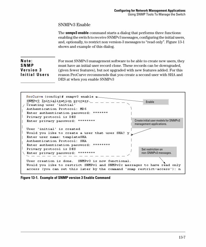
Configuring for Network Management Applications Using SNMP Tools To Manage the Switch
N o t e : S N M P V e r s i o n 3 I n i t i a l U s e r s
SNMPv3 Enable
The snmpv3 enable command starts a dialog that performs three functions: enabling the switch to receive SNMPv3 messages, configuring the initial users, and, optionally, to restrict non version-3 messages to “read only”. Figure 13-1 shows and example of this dialog.
For most SNMPv3 management software to be able to create new users, they must have an initial user record clone. These records can be downgraded, (given fewer features), but not upgraded with new features added. For this reason ProCurve recommends that you create a second user with SHA and DES at when you enable SNMPv3
i
Enable
Create initial user models for SNMPv3 management applications.
Set restr ction on non-SNMPv3 messages.
Figure 13-1. Example of SNMP version 3 Enable Command
13-7
Configuring for Network Management Applications Using SNMP Tools To Manage the Switch
SNMP Version 3 Users
The second step to using SNMPv3 on the switch is to configure the users that you assign to different groups. To establish users on the switch:
a. Add the users to the User table. This is done with the snmpv3 user command. To view the users in the list you use the show snmpv3 user command.
b. Assign users to Security Groups based on their security model.
C a u t i o n When stacking is enabled, SNMPv3 provides security only between an SNMPv3 management station and the stack manager. Communications between the stack commander and stack members is not secure.
Syntax: [no] snmpv3 user user_name [auth <md5 | sha><auth_pass>] [priv priv_pass]
Add or Deletes an user entry for snmpv3. Authorization
and Privacy are optional, but to use privacy you must
use authorization. When deleting a user only the
user_name is required
[auth <md5 | sha> <auth_pass>]
With authorization you can select either md5
authentication or sha authentication. The auth_pass
must be 6-32 characters in length and must be included
when authentication is included. (Default: None)
[priv priv_pass]
With privacy the switch only supports DES (56-bit)
encryption. The privacy password priv_pass must be
6-32 characters in length and must be included when
priv is included. (Default: None)
[no] snmpv3 group group_name user user_name sec-model <ver1| ver2c | ver3>
This command assigns or removes a user to a security
group for access right to the with. To delete a entry all
fields must be used.
group group_name
This is the group privileges that will be assigned to the
user. For more details see “Group Access Levels” on
page 13-11.
13-8
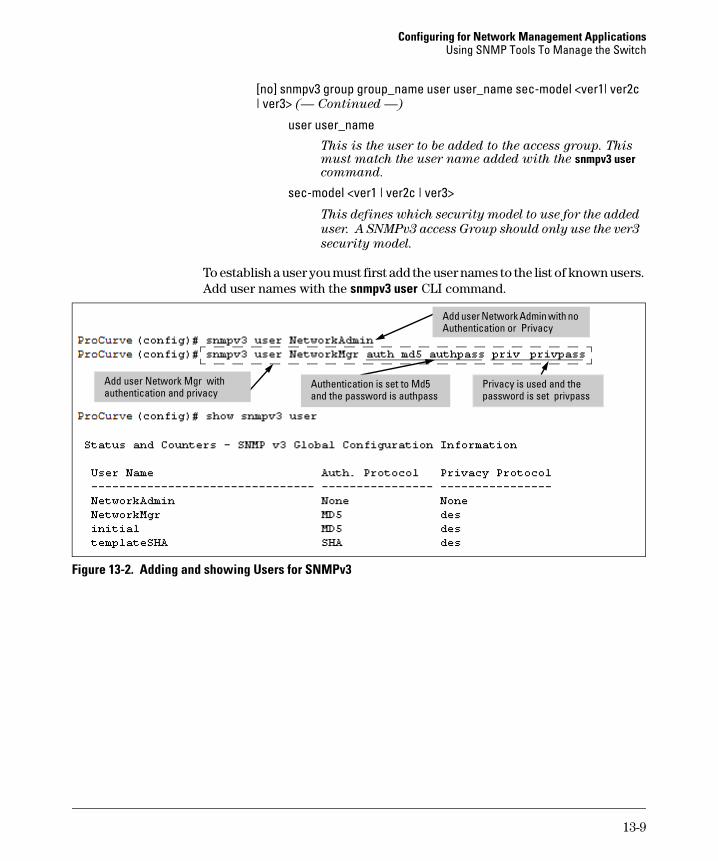
Configuring for Network Management Applications Using SNMP Tools To Manage the Switch
[no] snmpv3 group group_name user user_name sec-model <ver1| ver2c | ver3> (— Continued —)
user user_name This is the user to be added to the access group. This must match the user name added with the snmpv3 user command.
sec-model <ver1 | ver2c | ver3>
This defines which security model to use for the added
user. A SNMPv3 access Group should only use the ver3
security model.
To establish a user you must first add the user names to the list of known users. Add user names with the snmpv3 user CLI command.
iPrivacy
i
Add user Network Admin w th no Authentication or
Add user Network Mgr with authent cation and privacy
Privacy is used and the password is set privpass
Authentication is set to Md5 and the password is authpass
Figure 13-2. Adding and showing Users for SNMPv3
13-9
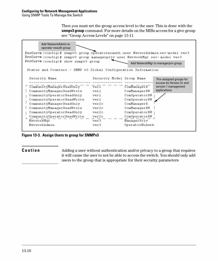
Configuring for Network Management Applications Using SNMP Tools To Manage the Switch
Then you must set the group access level to the user. This is done with the snmpv3 group command. For more details on the MIBs access for a give group see “Group Access Levels” on page 13-11.
Add NetworkAdmin to operator noauth group
Add NetwrokMgr to managerpriv group
Pre-assigned groups for access by Version 2c and version 1 management applications
Figure 13-3. Assign Users to group for SNMPv3
C a u t i o n Adding a user without authentication and/or privacy to a group that requires it will cause the user to not be able to access the switch. You should only add users to the group that is appropriate for their security parameters
13-10
Configuring for Network Management Applications Using SNMP Tools To Manage the Switch
Group Access Levels
The switch supports eight predefined group access levels. There are four levels for use with version 3 users and four are used for access by version 2c or version 1 management applications.
Group Name Group Access Type Group Read View Group Write View
managerpriv Ver3 Must have Authentication and Privacy
ManagerReadView ManagerWriteView
managerauth Ver3 Must have Authentication ManagerReadView ManagerWriteView
operatorauth Ver3 Must have Authentication OperatorReadView DiscoveryView
operatornoauth Ver3 No Authentication OperatorReadView DiscoveryView
commanagerrw Ver2c or Ver1 ManagerReadView ManagerWriteView
commanagerr Ver2c or Ver1 ManagerReadView DiscoveryView
comoperatorrw Ver2c or Ver1 OperatorReadView OperatorReadView
comoperatorr Ver2c or Ver1 OperatorReadView DiscoveryView
Each view allows you to view or modify a different set of MIBs.
■ Manager Read View – access to all managed objects
■ Manager Write View – access to all managed objects except the following: vacmContextTable, vacmAccessTable, vacmViewTreeFamilyTable
■ OperatorReadView – no access to icfSecurityMIB, ProCurveIpTftp-Mode, vacmContextTable, vacmAccessTable, vacmViewTreeFamilyTable, usmUserTable, snmpCommunityTable
■ Discovery View – Access limited to samplingProbe MIB.
N o t e All access groups and views are predefined on the switch. There is no method to modify or add groups or views to those that are pre-defined on the switch.
13-11
Configuring for Network Management Applications Using SNMP Tools To Manage the Switch
SNMP Communities
SNMP commuities are supported by the switch to allow management application that use version 2c or version 1 to access the switch. The communities are mapped to Group Access Levels that are used for version 2c or version 1 support. For more information see “Group Access Levels” on page 13-11. This mapping will happen automatically based on the communities access privileges, but special mappings can be added with the snmpv3 community command.
Syntax: [no] snmpv3 community This command maps or removes a mapping of a community name to a group access level. To remove a mapping you only need the index_name.
< index < index-name >>
This is an index number or title for the mapping. The values of 1-5 are reserved and can not be mapped.
< name < com-name >>
This is the community name that is being mapped to a group access level
< sec-name < security-name >>
This is the group level that the community is being mapped. For more information see “Group Access Levels” on page 13-11.
< tag < tag-value >>
This is used to specify which target address may have access via this index reference.
13-12
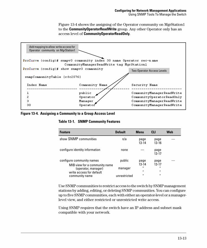
Configuring for Network Management Applications Using SNMP Tools To Manage the Switch
Figure 13-4 shows the assigning of the Operator community on MgrStation1 to the CommunityOperatorReadWrite group. Any other Operator only has an access level of CommunityOperatorReadOnly.
iity
Add mapp ng to allow write access for Operator commun on MgrStation1
Two Operator Access Levels
Figure 13-4. Assigning a Community to a Group Access Level
Table 13-1. SNMP Community Features
Feature Default Menu CLI Web
show SNMP communities n/a page page — 13-14 13-16
configure identity information none — page 13-17
configure community names public page page — MIB view for a community name
(operator, manager) write access for default
manager 13-14
“ “
13-17 “ “
community name unrestricted “ “
Use SNMP communities to restrict access to the switch by SNMP management stations by adding, editing, or deleting SNMP communities. You can configure up to five SNMP communities, each with either an operator-level or a manager-level view, and either restricted or unrestricted write access.
Using SNMP requires that the switch have an IP address and subnet mask compatible with your network.
13-13
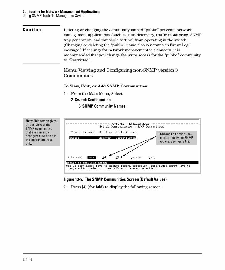
Configuring for Network Management Applications Using SNMP Tools To Manage the Switch
C a u t i o n Deleting or changing the community named “public” prevents network management applications (such as auto-discovery, traffic monitoring, SNMP trap generation, and threshold setting) from operating in the switch. (Changing or deleting the “public” name also generates an Event Log message.) If security for network management is a concern, it is recommended that you change the write access for the “public” community to “Restricted”.
Menu: Viewing and Configuring non-SNMP version 3 Communities
To View, Edit, or Add SNMP Communities:
1. From the Main Menu, Select:
2. Switch Configuration... 6. SNMP Community Names
Note: This screen gives an overview of the SNMP communities that are currently configured. All fields in this screen are read-only.
iAdd and Ed t options are used to modify the SNMP options. See figure 8-2.
Figure 13-5. The SNMP Communities Screen (Default Values)
2. Press [A] (for Add) to display the following screen:
13-14
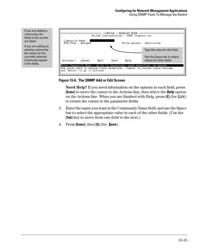
Configuring for Network Management Applications Using SNMP Tools To Manage the Switch
If you are adding a community, the fields in this screen are blank.
If you are editing an existing community, the values for the currently selected Community appear in the fields.
Type the value for this field.
Use the Space bar to select values for other fields
Figure 13-6. The SNMP Add or Edit Screen
Need Help? If you need information on the options in each field, press [Enter] to move the cursor to the Actions line, then select the Help option on the Actions line. When you are finished with Help, press [E] (for Edit) to return the cursor to the parameter fields.
3. Enter the name you want in the Community Name field, and use the Space bar to select the appropriate value in each of the other fields. (Use the [Tab] key to move from one field to the next.)
4. Press [Enter], then [S] (for Save).
13-15
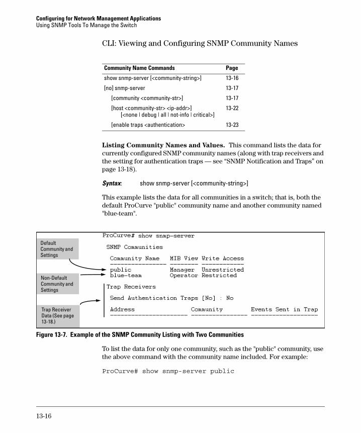
Configuring for Network Management Applications Using SNMP Tools To Manage the Switch
CLI: Viewing and Configuring SNMP Community Names
Community Name Commands Page
show snmp-server [<community-string>] 13-16
[no] snmp-server 13-17
[community <community-str>] 13-17
[host <community-str> <ip-addr>] 13-22 [<none | debug | all | not-info | critical>]
[enable traps <authentication> 13-23
Listing Community Names and Values. This command lists the data for currently configured SNMP community names (along with trap receivers and the setting for authentication traps — see “SNMP Notification and Traps” on page 13-18).
Syntax: show snmp-server [<community-string>]
This example lists the data for all communities in a switch; that is, both the default ProCurve "public" community name and another community named "blue-team".
Default
Non-Default i
Community and Settings
Commun ty and Settings
Trap Receiver Data (See page 13-18.)
Figure 13-7. Example of the SNMP Community Listing with Two Communities
To list the data for only one community, such as the "public" community, use the above command with the community name included. For example:
ProCurve# show snmp-server public
13-16
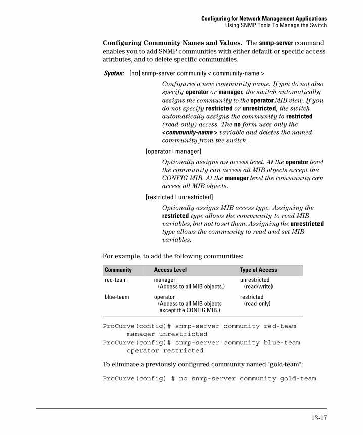
Configuring for Network Management Applications Using SNMP Tools To Manage the Switch
Configuring Community Names and Values. The snmp-server command enables you to add SNMP communities with either default or specific access attributes, and to delete specific communities.
Syntax: [no] snmp-server community < community-name >
Configures a new community name. If you do not also
specify operator or manager, the switch automatically
assigns the community to the operator MIB view. If you
do not specify restricted or unrestricted, the switch
automatically assigns the community to restricted (read-only) access. The no form uses only the
<community-name > variable and deletes the named
community from the switch.
[operator | manager]
Optionally assigns an access level. At the operator level
the community can access all MIB objects except the
CONFIG MIB. At the manager level the community can
access all MIB objects.
[restricted | unrestricted]
Optionally assigns MIB access type. Assigning the
restricted type allows the community to read MIB
variables, but not to set them. Assigning the unrestricted type allows the community to read and set MIB
variables.
For example, to add the following communities:
Community Access Level Type of Access
red-team manager unrestricted (Access to all MIB objects.) (read/write)
blue-team operator restricted (Access to all MIB objects (read-only) except the CONFIG MIB.)
ProCurve(config)# snmp-server community red-team manager unrestricted
ProCurve(config)# snmp-server community blue-team operator restricted
To eliminate a previously configured community named "gold-team":
ProCurve(config) # no snmp-server community gold-team
13-17
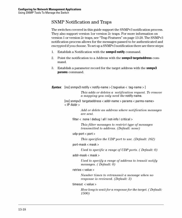
Configuring for Network Management Applications Using SNMP Tools To Manage the Switch
SNMP Notification and Traps
The switches covered in this guide support the SNMPv3 notification process. They also support version 1or version 2c traps. For more information on version 1 or version 2c traps, see “Trap Features” on page 13-20. The SNMPv3 notification process allows for the messages passed to be authenticated and encrypted if you choose. To set up a SNMPv3 notification there are three steps:
1. Establish a Notification with the snmpv3 notify command.
2. Point the notification to a Address with the snmpv3 targetaddress command.
3. Establish a parameter record for the target address with the snmpv3 params command.
Syntax: [no] snmpv3 notify < notify-name > [ tagvalue < tag-name > ] This adds or deletes a notification request. To remove a mapping you only need the notify-name.
[no] snmpv3 targetaddress < addr-name > params < parms-name> < IP-Addr >
Add or delete an address where notification messages
are sent.
filter < none | debug | all | not-info | critical >
This filter messages to restrict type of messages
transmitted to address. (Default: none)
udp-port < port >
This specifies the UDP port to use. (Default: 162)
port-mask < mask >
Used to specific a range of UDP ports. ( Default: 0)
addr-mask < mask >
Used to specify a range of address to transit notify
messages. ( Default: 0)
retries < value >
Number times to retransmit a message when no
response is reviewed. (Default: 3)
timeout < value >
How long to wait for a response for the target. ( Default:
1500)
13-18
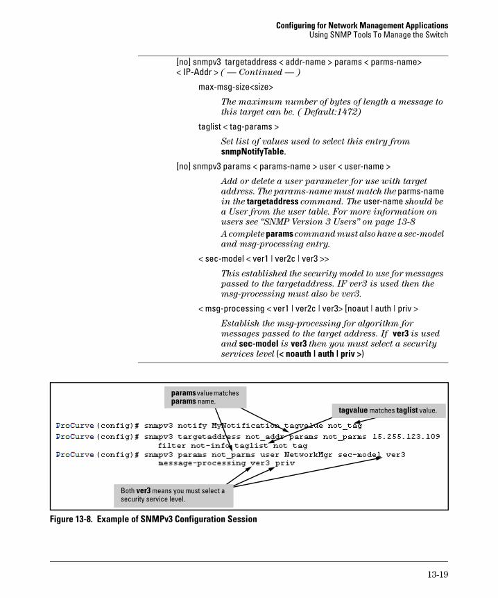
Configuring for Network Management Applications Using SNMP Tools To Manage the Switch
[no] snmpv3 targetaddress < addr-name > params < parms-name> < IP-Addr > ( — Continued — )
max-msg-size<size>
The maximum number of bytes of length a message to
this target can be. ( Default:1472)
taglist < tag-params >
Set list of values used to select this entry from
snmpNotifyTable.
[no] snmpv3 params < params-name > user < user-name >
Add or delete a user parameter for use with target
address. The params-name must match the parms-name in the targetaddress command. The user-name should be
a User from the user table. For more information on
users see “SNMP Version 3 Users” on page 13-8
A complete params command must also have a sec-model
and msg-processing entry.
< sec-model < ver1 | ver2c | ver3 >>
This established the security model to use for messages
passed to the targetaddress. IF ver3 is used then the
msg-processing must also be ver3.
< msg-processing < ver1 | ver2c | ver3> [noaut | auth | priv >
Establish the msg-processing for algorithm for
messages passed to the target address. If ver3 is used
and sec-model is ver3 then you must select a security
services level (< noauth | auth | priv >)
taglist
l
ver3
tagvalue matches value.
params va ue matches params name.
Both means you must select a security service level.
Figure 13-8. Example of SNMPv3 Configuration Session
13-19
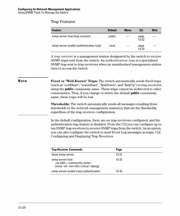
Configuring for Network Management Applications Using SNMP Tools To Manage the Switch
Trap Features
Feature Menu CLIDefault Web
snmp-server host (trap receiver) public — page — 13-22
snmp-server enable (authentication trap) none — page — 13-23
A trap receiver is a management station designated by the switch to receive SNMP traps sent from the switch. An authentication trap is a specialized SNMP trap sent to trap receivers when an unauthorized management station tries to access the switch.
N o t e Fixed or "Well-Known" Traps: The switch automatically sends fixed traps (such as "coldStart", "warmStart", "linkDown", and "linkUp") to trap receivers using the public community name. These traps cannot be redirected to other communities. Thus, if you change or delete the default public community name, these traps will be lost.
Thresholds: The switch automatically sends all messages resulting from thresholds to the network management station(s) that set the thresholds, regardless of the trap receiver configuration.
In the default configuration, there are no trap receivers configured, and the authentication trap feature is disabled. From the CLI you can configure up to ten SNMP trap receivers to receive SNMP traps from the switch. As an option, you can also configure the switch to send Event Log messages as traps. CLI: Configuring and Displaying Trap Receivers
Trap Receiver Commands Page
show snmp-server 13-21
snmp-server host 13-22 <ip-addr> <community-name> [none | all | non-info| critical | debug]
snmp-server enable traps authentication 13-22
13-20
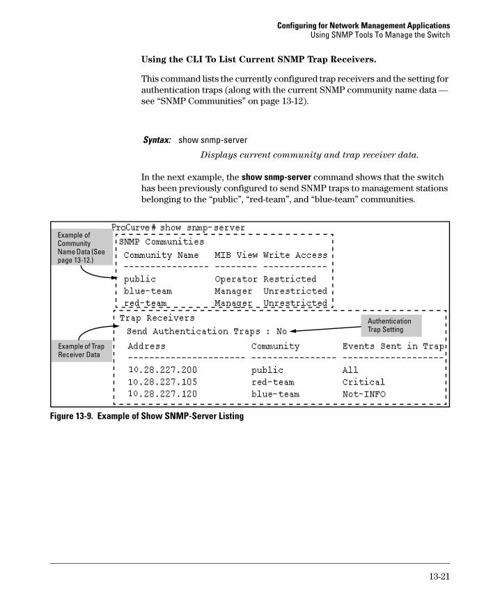
Configuring for Network Management Applications Using SNMP Tools To Manage the Switch
Using the CLI To List Current SNMP Trap Receivers.
This command lists the currently configured trap receivers and the setting for authentication traps (along with the current SNMP community name data — see “SNMP Communities” on page 13-12).
Syntax: show snmp-server
Displays current community and trap receiver data.
In the next example, the show snmp-server command shows that the switch has been previously configured to send SNMP traps to management stations belonging to the “public”, “red-team”, and “blue-team” communities.
lCommunity
Authentication
Examp e of
Name Data (See page 13-12.)
Example of Trap Receiver Data
Trap Setting
Figure 13-9. Example of Show SNMP-Server Listing
13-21
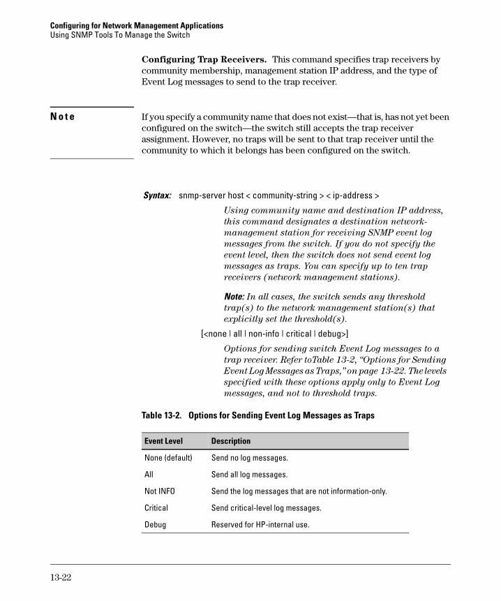
Configuring for Network Management Applications Using SNMP Tools To Manage the Switch
Configuring Trap Receivers. This command specifies trap receivers by community membership, management station IP address, and the type of Event Log messages to send to the trap receiver.
N o t e If you specify a community name that does not exist—that is, has not yet been configured on the switch—the switch still accepts the trap receiver assignment. However, no traps will be sent to that trap receiver until the community to which it belongs has been configured on the switch.
Syntax: snmp-server host < community-string > < ip-address >
Using community name and destination IP address,
this command designates a destination network-
management station for receiving SNMP event log
messages from the switch. If you do not specify the
event level, then the switch does not send event log
messages as traps. You can specify up to ten trap
receivers (network management stations).
Note: In all cases, the switch sends any threshold
trap(s) to the network management station(s) that
explicitly set the threshold(s).
[<none | all | non-info | critical | debug>]
Options for sending switch Event Log messages to a
trap receiver. Refer toTable 13-2, “Options for Sending
Event Log Messages as Traps,” on page 13-22. The levels
specified with these options apply only to Event Log
messages, and not to threshold traps.
Table 13-2. Options for Sending Event Log Messages as Traps
Event Level Description
None (default) Send no log messages.
All Send all log messages.
Not INFO Send the log messages that are not information-only.
Critical Send critical-level log messages.
Debug Reserved for HP-internal use.
13-22
Configuring for Network Management Applications Using SNMP Tools To Manage the Switch
For example, to configure a trap receiver in a community named "red-team" with an IP address of 10.28.227.130 to receive only "critical" log messages:
ProCurve(config)# snmp-server trap-receiver red-team 10.28.227.130 critical
N o t e s To replace one community name with another for the same IP address, you must use no snmp-server host < community-name> < ip-address > to delete the unwanted community name. Otherwise, adding a new community name with an IP address already in use with another community name simply creates two allowable community name entries for the same management station.
If you do not specify the event level ([<none | all | non-info | critical | debug>]) then the switch does not send event log messages as traps. "Well-Known" traps and threshold traps (if configured) will still be sent.
Using the CLI To Enable Authentication Traps
N o t e For this feature to operate, one or more trap receivers must be configured on the switch. See “Configuring Trap Receivers” on page 13-22.
Using the CLI To Enable Authentication Traps.
Syntax: [no] snmp-server enable traps authentication
Enables or disables sending an authentication trap to the
configured trap receiver(s) if an unauthorized management
station attempts to access the switch.
For example:
ProCurve(config)# snmp-server enable traps authentication
Check the Event Log in the console interface to help determine why the authentication trap was sent. (Refer to “Using Logging To Identify Problem Sources” on page C-23.)
13-23
Configuring for Network Management Applications Using SNMP Tools To Manage the Switch
Advanced Management: RMON
The switches covered in this guide support RMON (Remote Monitoring) on all connected network segments. This allows for troubleshooting and optimizing your network. The following RMON groups are supported:
■ Ethernet Statistics (except the numbers of packets of different frame sizes)
■ Alarm
■ History (of the supported Ethernet statistics)
■ Event
The RMON agent automatically runs in the switch. Use the RMON management station on your network to enable or disable specific RMON traps and events.
13-24
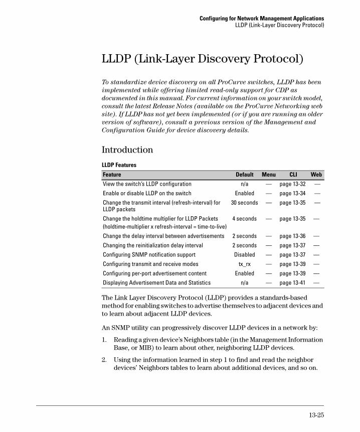
Configuring for Network Management Applications LLDP (Link-Layer Discovery Protocol)
LLDP (Link-Layer Discovery Protocol)
To standardize device discovery on all ProCurve switches, LLDP has been
implemented while offering limited read-only support for CDP as
documented in this manual. For current information on your switch model,
consult the latest Release Notes (available on the ProCurve Networking web
site). If LLDP has not yet been implemented (or if you are running an older
version of software), consult a previous version of the Management and
Configuration Guide for device discovery details.
Introduction
LLDP Features
Default MenuFeature CLI Web
View the switch’s LLDP configuration n/a — page 13-32 —
Enable or disable LLDP on the switch Enabled — page 13-34 —
Change the transmit interval (refresh-interval) for 30 seconds — page 13-35 — LLDP packets
Change the holdtime multiplier for LLDP Packets 4 seconds — page 13-35 — (holdtime-multiplier x refresh-interval = time-to-live)
Change the delay interval between advertisements 2 seconds — page 13-36 —
Changing the reinitialization delay interval 2 seconds — page 13-37 —
Configuring SNMP notification support Disabled — page 13-37 —
Configuring transmit and receive modes tx_rx — page 13-39 —
Configuring per-port advertisement content Enabled — page 13-39 —
Displaying Advertisement Data and Statistics n/a — page 13-41 —
The Link Layer Discovery Protocol (LLDP) provides a standards-based method for enabling switches to advertise themselves to adjacent devices and to learn about adjacent LLDP devices.
An SNMP utility can progressively discover LLDP devices in a network by:
1. Reading a given device’s Neighbors table (in the Management Information Base, or MIB) to learn about other, neighboring LLDP devices.
2. Using the information learned in step 1 to find and read the neighbor devices’ Neighbors tables to learn about additional devices, and so on.
13-25
Configuring for Network Management Applications LLDP (Link-Layer Discovery Protocol)
Also, by using show commands to access the switch’s neighbor database for information collected by an individual switch, system administrators can learn about other devices connected to the switch, including device type (capability) and some configuration information.
LLDP Terminology
Adjacent Device: Refer to “Neighbor or Neighbor Device”.
Advertisement: See LLDPDU.
Active Port: A port linked to another active device (regardless of whether STP is blocking the link).
LLDP: Link Layer Discovery Protocol. ProCurve switches are compatible with IEEE 802.1AB-2005.
LLDP-Aware: A device that has LLDP in its operating code, regardless of whether LLDP is enabled or disabled.
LLDP Device: A switch, server, router, or other device running LLDP.
LLDP Neighbor: An LLDP device that is either directly connected to another LLDP device or connected to that device by another, non-LLDP Layer 2 device (such as a hub) Note that an 802.1D-compliant switch does not forward LLDP data packets even if it is not LLDP-aware.
LLDPDU (LLDP Data Unit): LLDP data packets are transmitted on active links and include multiple TLVs containing global and per-port switch information. In this guide, LLDPDUs are termed “advertisements” or “packets”.
MIB (Management Information Base): An internal database the switch maintains for configuration and performance information.
Neighbor: See “LLDP Neighbor”.
Non_LLDP Device: A device that is not capable of LLDP operation.
TLV (Type-Length-Value): A data unit that includes a data type field, a data unit length field (in bytes), and a field containing the actual data the unit is designed to carry (as an alphanumeric string, a bitmap, or a subgroup of information). Some TLVs include subelements that occur as separate data points in displays of information maintained by the switch for LLDP advertisements. (That is, some TLVs include multiple data points or subelements.)
13-26
Configuring for Network Management Applications LLDP (Link-Layer Discovery Protocol)
General LLDP Operation
An LLDP packet contains data about the transmitting switch and port. The switch advertises itself to adjacent (neighbor) devices by transmitting LLDP data packets out all ports on which outbound LLDP is enabled, and reading LLDP advertisements from neighbor devices on ports that are inbound LLDP-enabled. (LLDP is a one-way protocol and does not include any acknowledgement mechanism.) An LLDP-enabled port receiving LLDP packets inbound from neighbor devices stores the packet data in a Neighbor database (MIB).
N o t e Ports can also be enabled for reading CDP packets and storing the CDP data in an LLDP-compatible version. See “LLDP and CDP Data Management” on page 13-50 for details.
Packet Boundaries in a Network Topology ■ Where multiple LLDP devices are directly connected, an outbound LLDP
packet travels only to the next LLDP device. An LLDP-capable device does not forward LLDP packets to any other devices, regardless of whether they are LLDP-capable.
■ An intervening hub or repeater forwards the LLDP packets it receives in the same manner as any other multicast packets it receives. Thus, two LLDP switches joined by a hub or repeater handle LLDP traffic in the same way that they would if directly connected.
■ Any intervening 802.1D device, or Layer-3 device that is either LLDP-unaware or has disabled LLDP operation, drops the packet.
LLDP Configuration Options
Enable or Disable LLDP on the Switch. In the default configuration, LLDP is globally enabled on the switch. To prevent transmission or receipt of LLDP traffic, you can disable LLDP operation (page 13-34).
Change the Frequency of LLDP Packet Transmission to Neighbor
Devices. On a global basis, you can increase or decrease the frequency of outbound LLDP advertisements (page 13-35).
Change the Time-To-Live for LLDP Packets Sent to Neighbors. On a global basis, you can increase or decrease the time that the information in an LLDP packet outbound from the switch will be maintained in a neighbor LLDP device (page 13-35).
13-27
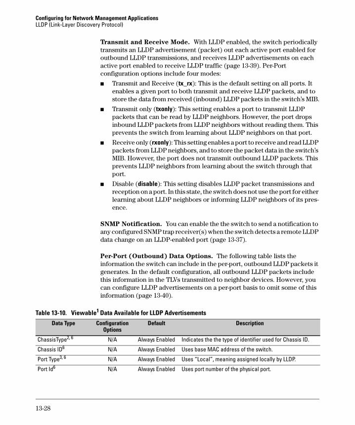
Configuring for Network Management Applications LLDP (Link-Layer Discovery Protocol)
Transmit and Receive Mode. With LLDP enabled, the switch periodically transmits an LLDP advertisement (packet) out each active port enabled for outbound LLDP transmissions, and receives LLDP advertisements on each active port enabled to receive LLDP traffic (page 13-39). Per-Port configuration options include four modes:
■ Transmit and Receive (tx_rx): This is the default setting on all ports. It enables a given port to both transmit and receive LLDP packets, and to store the data from received (inbound) LLDP packets in the switch’s MIB.
■ Transmit only (txonly): This setting enables a port to transmit LLDP packets that can be read by LLDP neighbors. However, the port drops inbound LLDP packets from LLDP neighbors without reading them. This prevents the switch from learning about LLDP neighbors on that port.
■ Receive only (rxonly): This setting enables a port to receive and read LLDP packets from LLDP neighbors, and to store the packet data in the switch’s MIB. However, the port does not transmit outbound LLDP packets. This prevents LLDP neighbors from learning about the switch through that port.
■ Disable (disable): This setting disables LLDP packet transmissions and reception on a port. In this state, the switch does not use the port for either learning about LLDP neighbors or informing LLDP neighbors of its presence.
SNMP Notification. You can enable the the switch to send a notification to any configured SNMP trap receiver(s) when the switch detects a remote LLDP data change on an LLDP-enabled port (page 13-37).
Per-Port (Outbound) Data Options. The following table lists the information the switch can include in the per-port, outbound LLDP packets it generates. In the default configuration, all outbound LLDP packets include this information in the TLVs transmitted to neighbor devices. However, you can configure LLDP advertisements on a per-port basis to omit some of this information (page 13-40).
Table 13-10. Viewable1 Data Available for LLDP Advertisements
Data Type Configuration Default Description Options
ChassisType2, 6 N/A Always Enabled Indicates the the type of identifier used for Chassis ID.
Chassis ID6 N/A Always Enabled Uses base MAC address of the switch.
Port Type3, 6 N/A Always Enabled Uses “Local”, meaning assigned locally by LLDP.
Port Id6 N/A Always Enabled Uses port number of the physical port.
13-28
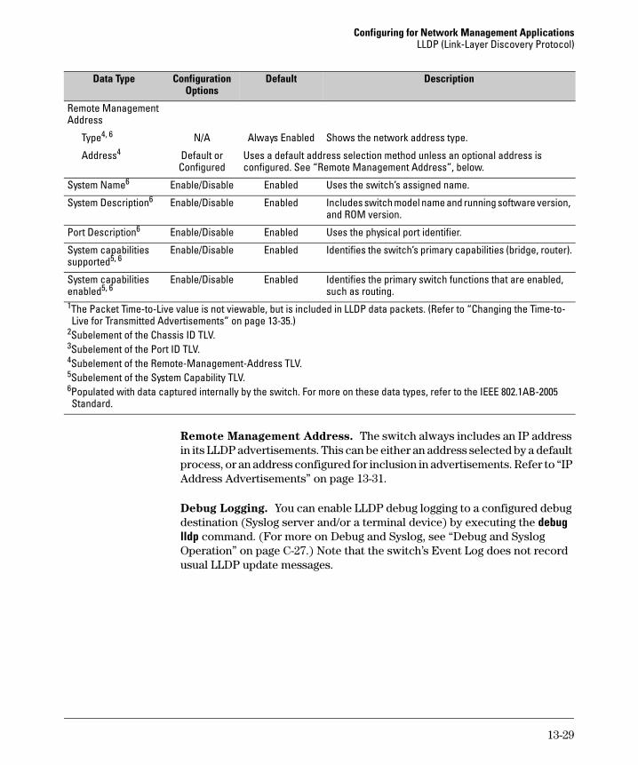
Configuring for Network Management Applications LLDP (Link-Layer Discovery Protocol)
Options DefaultData Type Configuration Description
Remote Management Address
Type4, 6 N/A Always Enabled Shows the network address type.
Address4 Default or Uses a default address selection method unless an optional address is Configured configured. See “Remote Management Address”, below.
System Name6 Enable/Disable Enabled Uses the switch’s assigned name.
System Description6 Enable/Disable Enabled Includes switch model name and running software version, and ROM version.
Port Description6 Enable/Disable Enabled Uses the physical port identifier.
System capabilities supported5, 6
Enable/Disable Enabled Identifies the switch’s primary capabilities (bridge, router).
System capabilities Enable/Disable Enabled Identifies the primary switch functions that are enabled, enabled5, 6 such as routing. 1The Packet Time-to-Live value is not viewable, but is included in LLDP data packets. (Refer to “Changing the Time-to-Live for Transmitted Advertisements” on page 13-35.)
2Subelement of the Chassis ID TLV. 3Subelement of the Port ID TLV. 4Subelement of the Remote-Management-Address TLV. 5Subelement of the System Capability TLV. 6Populated with data captured internally by the switch. For more on these data types, refer to the IEEE 802.1AB-2005 Standard.
Remote Management Address. The switch always includes an IP address in its LLDP advertisements. This can be either an address selected by a default process, or an address configured for inclusion in advertisements. Refer to “IP Address Advertisements” on page 13-31.
Debug Logging. You can enable LLDP debug logging to a configured debug destination (Syslog server and/or a terminal device) by executing the debug lldp command. (For more on Debug and Syslog, see “Debug and Syslog Operation” on page C-27.) Note that the switch’s Event Log does not record usual LLDP update messages.
13-29
Configuring for Network Management Applications LLDP (Link-Layer Discovery Protocol)
Options for Reading LLDP Information Collected by the Switch
You can extract LLDP information from the switch to identify adjacent LLDP devices. Options include:
■ Using the switch’s show lldp info command options to display data collected on adjacent LLDP devices—as well as the local data the switch is transmitting to adjacent LLDP devices (page 13-32).
■ Using an SNMP application that is designed to query the Neighbors MIB for LLDP data to use in device discovery and topology mapping. (This includes CDP data the switch has read and mapped to the LLDP counterpart.)
■ Using the walkmib command to display a listing of the LLDP MIB objects
LLDP Standards Compatibility
The features covered by this guide for the Series 2600 switches are compatible with the following LLDP-related standards:
■ IEEE 802.1AB-2005
■ RFC 2922 (PTOPO, or Physical Topology MIB)
■ RFC 2737 (Entity MIB)
■ RFC 2863 (Interfaces MIB)
13-30
Configuring for Network Management Applications LLDP (Link-Layer Discovery Protocol)
LLDP Operating Rules Port Trunking. LLDP manages trunked ports individually. That is, trunked ports are configured individually for LLDP operation, in the same manner as non-trunked ports. Also, LLDP sends separate advertisements on each port in a trunk, and not on a per-trunk basis. Similarly, LLDP data received through trunked ports is stored individually, per-port.
IP Address Advertisements. In the default operation, if a port belongs to only one static VLAN, then the port advertises the lowest-order IP address configured on that VLAN. If a port belongs to multiple VLANs, then the port advertises the lowest-order IP address configured on the VLAN with the lowest VID. If the qualifying VLAN does not have an IP address, the port advertises 127.0.0.1 as its IP address. For example, if the port is a member of the default VLAN (VID = 1), and there is an IP address configured for the default VLAN, then the port advertises this IP address. In the default operation, the IP address that LLDP uses can be an address acquired by DHCP or Bootp.
You can override the default operation by configuring the port to advertise any IP address that is manually configured on the switch, even if the port does not belong to the VLAN configured with the selected IP address (page 13-39). (Note that LLDP cannot be configured through the CLI to advertise an addresses acquired through DHCP or Bootp. However, as mentioned above, in the default LLDP configuration, if the lowest-order IP address on the VLAN with the lowest VID for a given port is a DHCP or Bootp address, then the switch includes this address in its LLDP advertisements unless another address is configured for advertisements on that port.) Also, although LLDP allows configuring multiple remote management addresses on a port, only the lowest-order address configured on the port will be included in outbound advertisements. Attempting to use the CLI to configure LLDP with an IP address that is either not configured on a VLAN, or has been acquired by DHCP or Bootp results in the following error message.
xxx.xxx.xxx.xxx: This IP address is not configured or is a DHCP address.
Spanning-Tree Blocking. Spanning tree does not prevent LLDP packet transmission or receipt on STP-blocked links.
802.1x Blocking. Ports blocked by 802.1x operation do not allow transmission or receipt of LLDP packets.
13-31
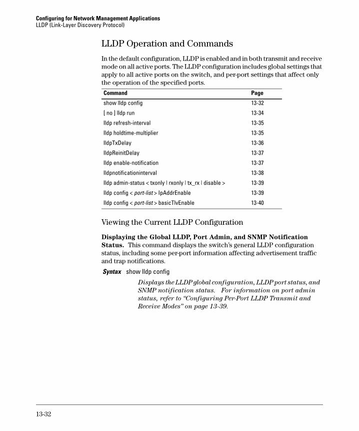
Configuring for Network Management Applications LLDP (Link-Layer Discovery Protocol)
LLDP Operation and Commands
In the default configuration, LLDP is enabled and in both transmit and receive mode on all active ports. The LLDP configuration includes global settings that apply to all active ports on the switch, and per-port settings that affect only the operation of the specified ports.
Command Page
show lldp config 13-32
13-34
13-35
13-35
13-36
13-37
13-37
13-38
[ no ] lldp run
lldp refresh-interval
lldp holdtime-multiplier
lldpTxDelay
lldpReinitDelay
lldp enable-notification
lldpnotificationinterval
lldp admin-status < txonly | rxonly | tx_rx | disable > 13-39
lldp config < port-list > IpAddrEnable 13-39
lldp config < port-list > basicTlvEnable 13-40
Viewing the Current LLDP Configuration
Displaying the Global LLDP, Port Admin, and SNMP Notification
Status. This command displays the switch’s general LLDP configuration status, including some per-port information affecting advertisement traffic and trap notifications.
Syntax show lldp config
Displays the LLDP global configuration, LLDP port status, and
SNMP notification status. For information on port admin
status, refer to “Configuring Per-Port LLDP Transmit and
Receive Modes” on page 13-39.
13-32
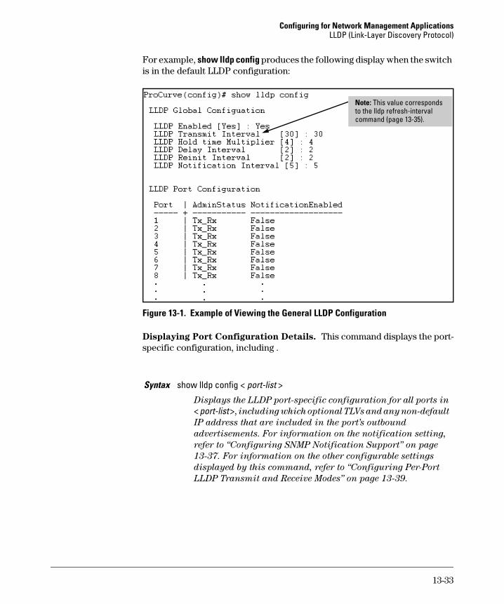
Configuring for Network Management Applications LLDP (Link-Layer Discovery Protocol)
For example, show lldp config produces the following display when the switch is in the default LLDP configuration:
Note: This value corresponds to the lldp refresh-interval command (page 13-35).
Figure 13-1. Example of Viewing the General LLDP Configuration
Displaying Port Configuration Details. This command displays the port-specific configuration, including .
Syntax show lldp config < port-list >
Displays the LLDP port-specific configuration for all ports in
< port-list >, including which optional TLVs and any non-default
IP address that are included in the port’s outbound
advertisements. For information on the notification setting,
refer to “Configuring SNMP Notification Support” on page
13-37. For information on the other configurable settings
displayed by this command, refer to “Configuring Per-Port
LLDP Transmit and Receive Modes” on page 13-39.
13-33
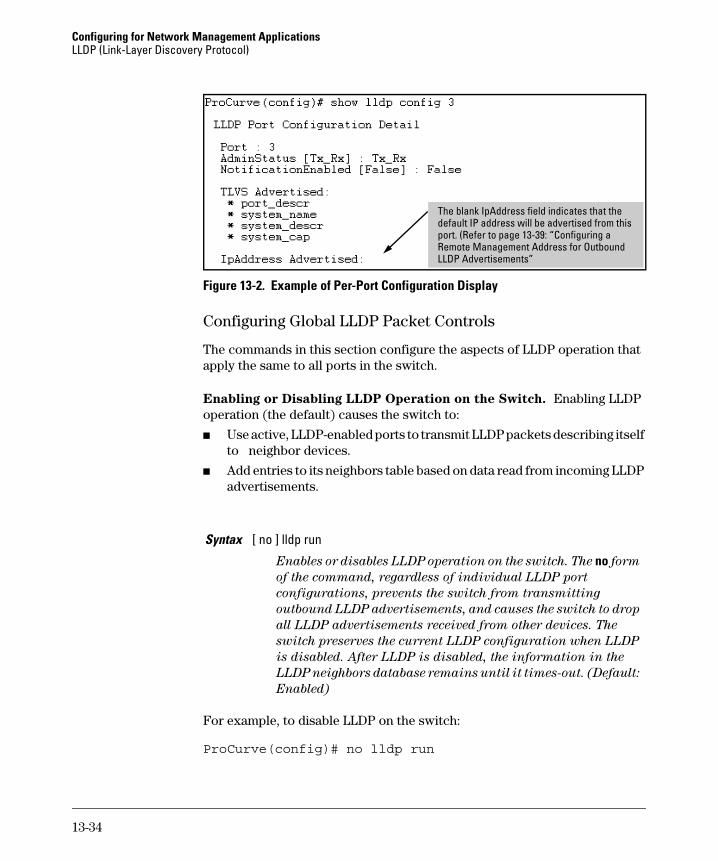
Configuring for Network Management Applications LLDP (Link-Layer Discovery Protocol)
ii
i
The blank IpAddress field ind cates that the default IP address will be advert sed from this port. (Refer to page 13-39: “Configur ng a Remote Management Address for Outbound LLDP Advertisements”
Figure 13-2. Example of Per-Port Configuration Display
Configuring Global LLDP Packet Controls
The commands in this section configure the aspects of LLDP operation that apply the same to all ports in the switch.
Enabling or Disabling LLDP Operation on the Switch. Enabling LLDP operation (the default) causes the switch to:
■ Use active, LLDP-enabled ports to transmit LLDP packets describing itself to neighbor devices.
■ Add entries to its neighbors table based on data read from incoming LLDP advertisements.
Syntax [ no ] lldp run
Enables or disables LLDP operation on the switch. The no form
of the command, regardless of individual LLDP port
configurations, prevents the switch from transmitting
outbound LLDP advertisements, and causes the switch to drop
all LLDP advertisements received from other devices. The
switch preserves the current LLDP configuration when LLDP
is disabled. After LLDP is disabled, the information in the
LLDP neighbors database remains until it times-out. (Default:
Enabled)
For example, to disable LLDP on the switch:
ProCurve(config)# no lldp run
13-34
Configuring for Network Management Applications LLDP (Link-Layer Discovery Protocol)
Changing the Transmission Interval for LLDP Packets. This interval controls how often active ports retransmit advertisements to their neighbors.
Syntax lldp refresh-interval < 5 - 32768 >
Changes the interval between consecutive transmissions of
LLDP advertisements on any given port. (Default: 30 seconds)
Note: The refresh-interval must be greater than or equal to
(4 x delay-interval). (The default delay-interval is 2). For
example, with the default delay-interval, the lowest refresh-interval you can use is 8 seconds (4 x 2 = 8). Thus, if you want
a refresh-interval of 5 seconds, you must first change the delay
interval to 1 (that is, 4 x 1 < 5). If you want to change the delay-interval, use the setmib command. (Refer to page 13-36.)
Changing the Time-to-Live for Transmitted Advertisements. The Time-to-Live value (in seconds) for all LLDP advertisements transmitted from a switch is controlled by the switch that generates the advertisement, and determines how long an LLDP neighbor retains the advertised data before discarding it. The Time-to-Live value is the result of multiplying the refresh-interval by the holdtime-multiplier described below.
Syntax lldp holdtime-multiplier < 2 - 10 >
Changes the multiplier an LLDP switch uses to calculate the
Time-to-Live for the LLDP advertisements it generates and
transmits to LLDP neighbors. When the Time-to-Live for a
given advertisement expires the advertised data is deleted from
the neighbor switch’s MIB. (Default: 4; Range: 2 - 10)
For example, if the refresh-interval on the switch is 15 seconds and the holdtime-multiplier is at the default, the Time-to-Live for advertisements transmitted from the switch is 60 seconds (4 x 15). To reduce the Time-to-Live, you could lower the holdtime-interval to 2, which would result in a Time-to-Live of 30 seconds.
ProCurve(config)# lldp holdtime-multiplier 2
13-35
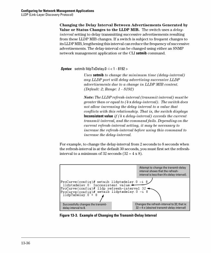
Configuring for Network Management Applications LLDP (Link-Layer Discovery Protocol)
Changing the Delay Interval Between Advertisements Generated by
Value or Status Changes to the LLDP MIB. The switch uses a delay-
interval setting to delay transmitting successive advertisements resulting from these LLDP MIB changes. If a switch is subject to frequent changes to its LLDP MIB, lengthening this interval can reduce the frequency of successive advertisements. The delay-interval can be changed using either an SNMP network management application or the CLI setmib command.
Syntax setmib lldpTxDelay.0 -i < 1 - 8192 >
Uses setmib to change the minimum time (delay-interval)
any LLDP port will delay advertising successive LLDP
advertisements due to a change in LLDP MIB content.
(Default: 2; Range: 1 - 8192)
Note: The LLDP refresh-interval (transmit interval) must be
greater than or equal to (4 x delay-interval). The switch does
not allow increasing the delay interval to a value that
conflicts with this relationship. That is, the switch displays
Inconsistent value if (4 x delay-interval) exceeds the current
transmit interval, and the command fails. Depending on the
current refresh-interval setting, it may be necessary to
increase the refresh-interval before using this command to
increase the delay-interval.
For example, to change the delay-interval from 2 seconds to 8 seconds when the refresh-interval is at the default 30 seconds, you must first set the refresh-interval to a minimum of 32 seconds (32 = 4 x 8).
ii
l( i )l
Attempt to change the transmit-delay nterval shows that the refresh-nterval is less than (4 x delay-interval).
Changes the refresh-interva to 32; that is: 32 = 4 x desired transmit-delay nterval
Successfully changes the transmit-delay interva to 8.
Figure 13-3. Example of Changing the Transmit-Delay Interval
13-36
Configuring for Network Management Applications LLDP (Link-Layer Discovery Protocol)
Changing the Reinitialization Delay Interval. In the default configuration, a port receiving a disable command followed immediately by a txonly, rxonly, or tx_rx command delays reinitializing for two seconds, during which time LLDP operation remains disabled. If an active port is subjected to frequent toggling between the LLDP disabled and enabled states, LLDP advertisements are more frequently transmitted to the neighbor device. Also, the neighbor table in the adjacent device will change more frequently, as it deletes, then replaces LLDP data for the affected port which, in turn, generates SNMP traps (if trap receivers and SNMP notification are configured). All of this can unnecessarily increase network traffic. Extending the reinitializationdelay interval delays the port’s ability to reinitialize and generate LLDP traffic following an LLDP disable/enable cycle.
Syntax setmib lldpReinitDelay.0 -i < 1 - 10 >
Uses setmib to change the minimum time (reinitialization
delay interval) an LLDP port will wait before reinitializing
after receiving an LLDP disable command followed closely by
a txonly or tx_rx command. The delay interval commences
with execution of the lldp admin-status < port-list > disable command. (Default: 2 seconds; Range: 1 - 10 seconds)
For example, the following command changes the reinitialization delay interval to five seconds:
ProCurve(config)# setmib lldpreinitdelay.0 -i 5
Configuring SNMP Notification Support
You can enable SNMP trap notification of LLDP data changes detected on advertisements received from neighbor devices, and control the interval between successive notifications of data changes on the same neighbor.
Enabling LLDP Data Change Notification for SNMP Trap Receivers.
Syntax [ no ] lldp enable-notification < port-list >
Enables or disables each port in < port-list > for sending
notification to configured SNMP trap receiver(s) if an LLDP
data change is detected in an advertisement received on the
port from an LLDP neighbor. (Default: Disabled)
For information on configuring trap receivers in the switch,
refer to the chapter titled “Configuring for Network
Management Applications” in the Management and
Configuration Guide for your switch.
13-37
Configuring for Network Management Applications LLDP (Link-Layer Discovery Protocol)
For example, this command enables SNMP notification on ports 1 - 5:
ProCurve(config)# lldp enable-notification 1-5
Changing the Minimum Interval for Successive LLDP Data Change
Notifications for the Same Neighbor.
If LLDP trap notification is enabled on a port, a rapid succession of changes in LLDP information received in advertisements from one or more neighbors can generate a high number of traps. To reduce this effect, you can globally change the interval between successive notifications of neighbor data change.
Syntax setmib lldpnotificationinterval.0 -i < 1 - 3600 >
Globally changes the interval between successive traps
generated by the switch. If multiple traps are generated in the
specified interval, only the first trap will be sent. The
remaining traps will be suppressed. (A network management
application can periodically check the switch MIB to detect any
missed change notification traps. Refer to IEEE 802.1AB-2005
or later for more information.) (Default: 5 seconds)
For example, the following command limits change notification traps from a particular switch to one per minute.
ProCurve(config)# setmib lldpnotificationinterval.0 -i 60lldpNotificationInterval.0 = 60
13-38
Configuring for Network Management Applications LLDP (Link-Layer Discovery Protocol)
Configuring Per-Port LLDP Transmit and Receive Modes
These commands control LLDP advertisement traffic inbound and outbound on active ports.
Syntax lldp admin-status < port-list > < txonly | rxonly | tx_rx | disable >
With LLDP enabled on the switch in the default LLDP
configuration, each port is configured to transmit and receive
LLDP packets. These options enable you to control which ports
participate in LLDP traffic and whether the participating
ports allow LLDP traffic in only one direction or in both
directions.
txonly: Configures the specified port(s) to transmit LLDP pack
ets, but block inbound LLDP packets from neighbor devices.
rxonly: Configures the specified port(s) to receive LLDP packets
from neighbors, but block outbound packets to neighbors.
tx_rx: Configures the specified port(s) to both transmit and
receive LLDP packets. (This is the default setting.)
disable: Disables LLDP packet transmit and receive on the
specified port(s).
Configuring LLDP Per-Port Advertisement Content
In the default LLDP configuration, outbound advertisements from each port on the switch include both the mandatory and the optional data listed in the next two subsections.
Mandatory Data. An active LLDP port on the switch always includes the mandatory data in its outbound advertisements. LLDP collects the mandatory data, and, except for the Remote Management Address, you cannot use LLDP commands to configure the actual data.
■ Chassis Type (TLV subelement)
■ Chassis ID (TLV)
■ Port Type (TLV subelement)
■ Port ID (TLV)
■ Remote Management Address (TLV; actual IP address is a subelement that can be a default address or a configured address)
Configuring a Remote Management Address for Outbound LLDP
Advertisements. This is an optional command you can use to include a specific IP address in the outbound LLDP advertisements for specific ports.
13-39
Configuring for Network Management Applications LLDP (Link-Layer Discovery Protocol)
Syntax [ no ] lldp config < port-list > ipAddrEnable < ip-address >
Replaces the default IP address for the port with an IP
address you specify. This can be any IP address configured
in a static VLAN on the switch, even if the port does not
belong to the VLAN configured with the selected IP address.
The no form of the command deletes the specified IP
address. If there are no IP addresses configured as
management addresses, then the IP address selection
method returns to the default operation. (Default: The port
advertises the primary IP address of the lowest-numbered
VLAN (VID) to which it belongs. If there is no IP address
configured on the VLAN(s) to which the port belongs, and
the port is not configured to advertise an IP address from
any other (static) VLAN on the switch, then the port
advertises an address of 127.0.0.1.)
Note: This command does not accept either IP addresses
acquired through DHCP or Bootp, or IP addresses that are
not configured in a static VLAN on the switch
For example, if port 3 belongs to a subnetted VLAN that includes a secondary IP address of 10.10.10.100 and you wanted port 3 to use this secondary address in LLDP advertisements, you would need to execute the following command:
ProCurve(config)# lldp config 3 ipAddrEnable 10.10.10.100
Optional Data. You can configure an individual port or group of ports to exclude one or more of these data types from outbound LLDP advertisements. Note that optional data types, when enabled, are populated with data internal to the switch; that is, you cannot use LLDP commands to configure their actual content.
■ Port Description (TLV)
■ System Name (TLV)
■ System Description (TLV)
■ System Capabilities (TLV)
• System Capabilities Supported (TLV subelement)
• System Capabilities Enabled (TLV subelement)
13-40
Configuring for Network Management Applications LLDP (Link-Layer Discovery Protocol)
Syntax [ no ] lldp config < port-list > basicTlvEnable < TLV-Type >
port_descr
For outbound LLDP advertisements, includes an
alphanumeric string describing the port.
system_name
For outbound LLDP advertisements, includes the system’s
assigned name.
system_descr
For outbound LLDP advertisements, includes an
alphanumeric string describing the full name and version
identification for the system’s hardware type, software
version, and networking application.
system_cap
For outbound advertisements, includes a bitmask of
system capabilities (device functions) that are supported.
Also includes information on whether the capabilities are
enabled.
For example, if you wanted to exclude the system name from the outbound LLDP advertisements for all ports on a 2626 switch, you would use this command:
ProCurve(config)# no lldp config 1-26 basicTlvEnable system_name
If you later decided to reinstate the system name on ports 1-5, you would use this command:
ProCurve(config)# lldp config 1-5 basicTlvEnable system_name
Displaying Advertisement Data
Command Page
show lldp info local-device below
show lldp info remote-device 13-43
show lldp info stats 13-46
13-41
Configuring for Network Management Applications LLDP (Link-Layer Discovery Protocol)
Displaying Switch Information Available for Outbound Advertisements
These commands display the current switch information that will be used to populate outbound LLDP advertisements.
Syntax show lldp info local-device [ port-list ]
Without the [ port-list ] option, this command displays the global
switch information and the per-port information currently
available for populating outbound LLDP advertisements.
With the [ port-list ] option, this command displays only the
following port-specific information that is currently available
for outbound LLDP advertisements on the specified ports:
• PortType • PortId • PortDesc
Note: This command displays the information available on
the switch. Use the lldp config < port-list > command to change
the selection of information that is included in actual
outbound advertisements. In the default LLDP configuration,
all information displayed by this command is transmitted in
outbound advertisements.
For example, in the default configuration, the switch information currently available for outbound LLDP advertisements appears similar to the display in figure 13-4 on page page 13-43.
13-42
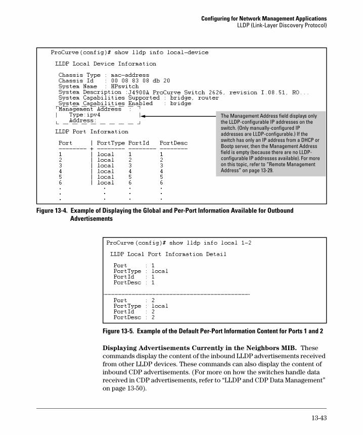
Configuring for Network Management Applications LLDP (Link-Layer Discovery Protocol)
i
)
fiell
i
The Management Address field d splays only the LLDP-configurable IP addresses on the switch. (Only manually-configured IP addresses are LLDP-configurable. If the switch has only an IP address from a DHCP or Bootp server, then the Management Address
d is empty (because there are no LLDP-configurable IP addresses availab e). For more on this top c, refer to “Remote Management Address” on page 13-29.
Figure 13-4. Example of Displaying the Global and Per-Port Information Available for Outbound Advertisements
Figure 13-5. Example of the Default Per-Port Information Content for Ports 1 and 2
Displaying Advertisements Currently in the Neighbors MIB. These commands display the content of the inbound LLDP advertisements received from other LLDP devices. These commands can also display the content of inbound CDP advertisements. (For more on how the switches handle data received in CDP advertisements, refer to “LLDP and CDP Data Management” on page 13-50).
13-43
Configuring for Network Management Applications LLDP (Link-Layer Discovery Protocol)
Syntax show lldp info remote-device [ port-list ]
Without the [ port-list ] option, this command provides a global
list of the individual devices it has detected by reading LLDP
advertisements (and also CDP advertisements). Discovered
devices are listed by the inbound port on which they were
discovered.
Multiple devices listed for a single port indicates either or both
of the following:
– A discovered device is transmitting both LLDP and CDP
packets with different chassis and port ID information.
– Multiple devices are connected to the switch through a hub.
Discovering the same device on multiple ports indicates that
the remote device may be connected to the switch in one of the
following ways:
– Through different VLANS using separate links. (This
applies to switches that use the same MAC address for all
configured VLANs.)
– Through different links in the same trunk.
– Through different links using the same VLAN. (In this
case, spanning-tree should be invoked to prevent a net
work topology loop. Note that LLDP packets travel on links
that spanning-tree blocks for other traffic types.)
With the [ port-list ] option, this command provides a listing of
the LLDP data that the switch has detected in advertisements
received on the specified ports. If neighbor data is read from
CDP advertisements, the switch remaps this information into
the switch’s LLDP neighbors MIB in addition to the CDP
Neighbors MIB.
For descriptions of the various types of information displayed
by these commands, refer to Table 13-10 on page 13-28.
13-44
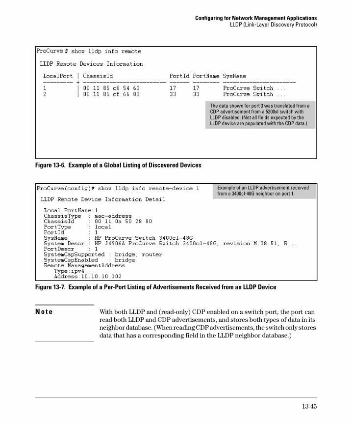
Configuring for Network Management Applications LLDP (Link-Layer Discovery Protocol)
)
The data shown for port 3 was translated from a CDP advertisement from a 5300xl switch with LLDP disabled. (Not all fields expected by the LLDP device are populated with the CDP data.
Figure 13-6. Example of a Global Listing of Discovered Devices
Example of an LLDP advertisement received from a 3400cl-48G neighbor on port 1.
Figure 13-7. Example of a Per-Port Listing of Advertisements Received from an LLDP Device
N o t e With both LLDP and (read-only) CDP enabled on a switch port, the port can read both LLDP and CDP advertisements, and stores both types of data in its neighbor database. (When reading CDP advertisements, the switch only stores data that has a corresponding field in the LLDP neighbor database.)
13-45
Configuring for Network Management Applications LLDP (Link-Layer Discovery Protocol)
Displaying LLDP Statistics
LLDP statistics are available on both a global and a per-port levels. Rebooting the switch resets the LLDP statistics counters to zero. Disabling the transmit and/or receive capability on a port “freezes” the related port counters at their current values.
Syntax show lldp info stats [ port-list ]
The global LLDP statistics command displays an overview of
neighbor detection activity on the switch, plus data on the
number of frames sent, received, and discarded per-port. The
per-port LLDP statistics command enhances the list of per-port
statistics provided by the global statistics command with some
additional per-port LLDP statistics.
Global LLDP Counters:
Neighbor Entries List Last Updated: Shows the elapsed time since
a neighbor was last added or deleted.
New Neighbor Entries Count: Shows the total of new LLDP
neighbors detected since the last switch reboot. Disconnecting,
then reconnecting a neighbor increments this counter.
Neighbor Entries Deleted Count: Shows the number of neighbor
deletions from the MIB for AgeOut Count and forced drops for
all ports. For example, if the admin status for port on a
neighbor device changes from tx_rx or txonly to disabled or
rxonly, then the neighbor device sends a “shutdown” packet out
the port and ceases transmitting LLDP frames out that port.
The device receiving the shutdown packet deletes all
information about the neighbor received on the applicable
inbound port and increments the counter .
Neighbor Entries Dropped Count: Shows the number of valid LLDP
neighbors the switch detected, but could not add. This can
occur, for example, when a new neighbor is detected when the
switch is already supporting the maximum number of
neighbors. Refer to “Neighbor Maximum” on page 13-49.
Neighbor Entries AgeOut Count: Shows the number of LLDP
neighbors dropped on all ports due to Time-to-Live expiring.
— Continued on the next page. —
13-46
Configuring for Network Management Applications LLDP (Link-Layer Discovery Protocol)
— Continued from the preceding page. —
Per-Port LLDP Counters:
NumFramesRecvd: Shows the total number of valid, inbound
LLDP advertisements received from any neighbor(s) on < port-list >. Where multiple neighbors are connected to a port through
a hub, this value is the total number of LLDP advertisements
received from all sources.
NumFramesSent: Shows the total number of LLDP
advertisements sent from < port-list >.
NumFramesDiscarded: Shows the total number of inbound LLDP
advertisements discarded by < port-list >. This can occur, for
example, when a new neighbor is detected on the port, but the
switch is already supporting the maximum number of
neighbors. Refer to “Neighbor Maximum” on page 13-49. This
can also be an indication of advertisement formatting
problems in the neighbor device.
Frames Invalid: Shows the total number of invalid LLDP
advertisements received on the port. An invalid advertisement
can be caused by header formatting problems in the neighbor
device.
TLVs Unrecognized: Shows the total number of LLDP TLVs
received on a port with a type value in the reserved range. This
could be caused by a basic management TLV from a later LLDP
version than the one currently running on the switch.
TLVs Discarded: Shows the total number of LLDP TLVs discarded
for any reason. In this case, the advertisement carrying the
TLV may be accepted, but the individual TLV was not usable.
Neighbor Ageouts: Shows the number of LLDP neighbors
dropped on the port due to Time-to-Live expiring.
13-47
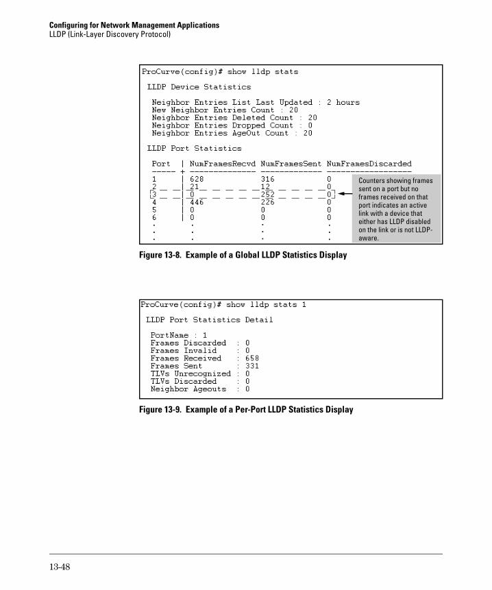
Configuring for Network Management Applications LLDP (Link-Layer Discovery Protocol)
Counters showing frames sent on a port but no frames received on that port indicates an active link with a device that either has LLDP disabled on the link or is not LLDP-aware.
Figure 13-8. Example of a Global LLDP Statistics Display
Figure 13-9. Example of a Per-Port LLDP Statistics Display
13-48
Configuring for Network Management Applications LLDP (Link-Layer Discovery Protocol)
LLDP Operating Notes
Neighbor Maximum. The neighbors table in the switch supports as many neighbors as there are ports on the switch. The switch can support multiple neighbors connected through a hub on a given port, but if the switch neighbor maximum is reached, advertisements from additional neighbors on the same or other ports will not be stored in the neighbors table unless some existing neighbors time-out or are removed.
LLDP Packet Forwarding: If CDP is globally disabled on a switch, the switch forwards CDP packets received from a neighbor CDP device instead of reading and dropping them. However, an 802.1D-compliant switch does not forward LLDP packets, regardless of whether LLDP is globally enabled or disabled on the switch.
One IP Address Advertisement Per-Port: LLDP advertises only one IP address per-port, even if multiple IP addresses are configured by lldp config < port-list > ipAddrEnable on a given port.
802.1Q VLAN Information. LLDP packets do not include 802.1Q header information, and are always handled as untagged packets.
Effect of 802.1X Operation. If 802.1X port security is enabled on a port and a connected device is not authorized, LLDP packets are not transmitted or received on that port. Any neighbor data stored in the neighbor MIB for that port prior to the unauthorized device connection remains in the MIB until it ages out. If an unauthorized device later becomes authorized, LLDP transmit and receive operation resumes.
Neighbor Data Can Remain in the Neighbor Database After the
Neighbor Is Disconnected. After disconnecting a neighbor LLDP device from the switch, the neighbor can continue to appear in the switch’s neighbor database for an extended period if the neighbor’s holdtime-multiplier is high; especially if the refresh-interval is large. Refer to “Changing the Time-to-Live for Transmitted Advertisements” on page 13-35.
13-49
Configuring for Network Management Applications LLDP (Link-Layer Discovery Protocol)
LLDP and CDP Data Management
This section describes points to note regarding LLDP (Link-Layer Discovery Protocol) and CDP (Cisco Discovery Protocol) data received by the switch from other devices. LLDP operation includes both transmitting LLDP packets to neighbor devices and reading LLDP packets received from neighbor devices. CDP operation is limited to reading incoming CDP packets from neighbor devices. (ProCurve switches do not generate CDP packets.)
LLDP and CDP Neighbor Data
With both LLDP and (read-only) CDP enabled on a switch port, the port can read both LLDP and CDP advertisements, and stores the data from both types of advertisements in its neighbor database. (The switch only stores CDP data that has a corresponding field in the LLDP neighbor database.) The neighbor database itself can be read by either LLDP or CDP methods or by using the show lldp commands. Take note of the following rules and conditions:
■ If the switch receives both LLDP and CDP advertisements on the same port from the same neighbor the switch stores this information as two separate entries if the advertisements have differences chassis ID and port ID information.
■ If the chassis and port ID information are the same, the switch stores this information as a single entry. That is, LLDP data overwrites the corresponding CDP data in the neighbor database if the chassis and port ID information in the LLDP and CDP advertisements received from the same device is the same.
■ Data read from a CDP packet does not support some LLDP fields, such as “System Descr”, “SystemCapSupported”, and “ChassisType”. For such fields, LLDP assigns relevant default values. Also:
• The LLDP “System Descr” field maps to CDP’s “Version” and “Platform” fields.
• The switch assigns “ChassisType” and “PortType” fields as “local” for both the LLDP and the CDP advertisements it receives.
• Both LLDP and CDP support the “System Capability” TLV. However, LLDP differentiates between what a device is capable of supporting and what it is actually supporting, and separates the two types of information into subelements of the System Capability TLV. CDP has only a single field for this data. Thus, when CDP System Capability data is mapped to LLDP, the same value appears in both LLDP System Capability fields.
• System Name and Port Descr are not communicated by CDP, and thus are not included in the switch’s Neighbors database.
13-50
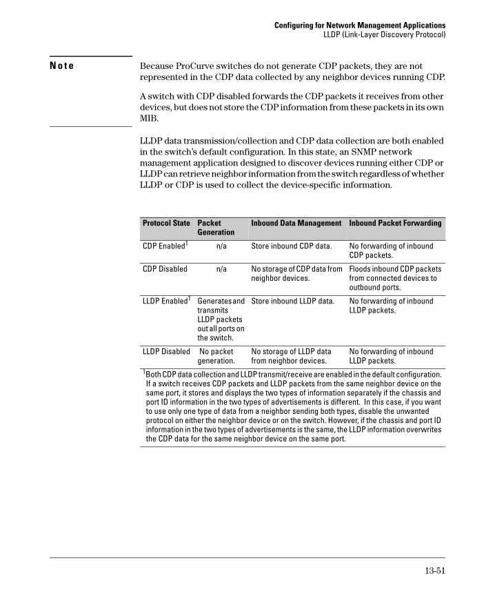
Configuring for Network Management Applications LLDP (Link-Layer Discovery Protocol)
N o t e Because ProCurve switches do not generate CDP packets, they are not represented in the CDP data collected by any neighbor devices running CDP.
A switch with CDP disabled forwards the CDP packets it receives from other devices, but does not store the CDP information from these packets in its own MIB.
LLDP data transmission/collection and CDP data collection are both enabled in the switch’s default configuration. In this state, an SNMP network management application designed to discover devices running either CDP or LLDP can retrieve neighbor information from the switch regardless of whether LLDP or CDP is used to collect the device-specific information.
Protocol State Packet Inbound Data Management
CDP Enabled1
Generation Inbound Packet Forwarding
n/a Store inbound CDP data. No forwarding of inbound CDP packets.
CDP Disabled n/a No storage of CDP data from Floods inbound CDP packets neighbor devices. from connected devices to
outbound ports.
LLDP Enabled1 Generates and Store inbound LLDP data. No forwarding of inbound transmits LLDP packets. LLDP packets out all ports on the switch.
LLDP Disabled No packet No storage of LLDP data No forwarding of inbound generation. from neighbor devices. LLDP packets.
1Both CDP data collection and LLDP transmit/receive are enabled in the default configuration. If a switch receives CDP packets and LLDP packets from the same neighbor device on the same port, it stores and displays the two types of information separately if the chassis and port ID information in the two types of advertisements is different. In this case, if you want to use only one type of data from a neighbor sending both types, disable the unwanted protocol on either the neighbor device or on the switch. However, if the chassis and port ID information in the two types of advertisements is the same, the LLDP information overwrites the CDP data for the same neighbor device on the same port.
13-51
Configuring for Network Management Applications LLDP (Link-Layer Discovery Protocol)
CDP Operation and Commands
By default the switches covered by this guide have CDP enabled on each port. This is a read-only capability, meaning that the switch can receive and store information about adjacent CDP devices but does not generate CDP packets.
When a CDP-enabled switch receives a CDP packet from another CDP device, it enters that device’s data in the CDP Neighbors table, along with the port number where the data was received (and does not forward the packet). The switch also periodically purges the table of any entries that have expired. (The hold time for any data entry in the switch’s CDP Neighbors table is configured in the device transmitting the CDP packet, and cannot be controlled in the switch receiving the packet.) A switch reviews the list of CDP neighbor entries every three seconds, and purges any expired entries.
Command Page
show cdp 13-52
show cdp neighbors [< port-list > detail] 13-53 [detail < port-list >]
[no] cdp run 13-54
[no] cdp enable < port-list > 13-54
N o t e For details on how to use an SNMP utility to retrieve information from the switch’s CDP Neighbors table maintained in the switch’s MIB (Management Information Base), refer to the documentation provided with the particular SNMP utility.
Viewing the Switch’s Current CDP Configuration. CDP is shown as enabled/disabled both globally on the switch and on a per-port basis.
Syntax: show cdp
Lists the switch’s global and per-port CDP configuration.
13-52
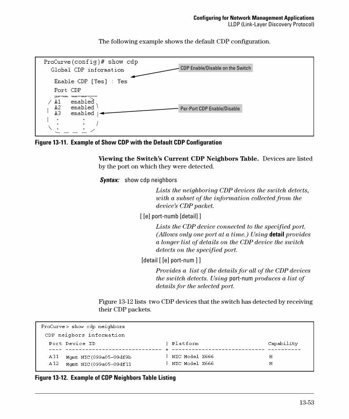
Configuring for Network Management Applications LLDP (Link-Layer Discovery Protocol)
The following example shows the default CDP configuration.
lCDP Enable/Disab e on the Switch
Per-Port CDP Enable/Disable
Figure 13-11. Example of Show CDP with the Default CDP Configuration
Viewing the Switch’s Current CDP Neighbors Table. Devices are listed by the port on which they were detected.
Syntax: show cdp neighbors
Lists the neighboring CDP devices the switch detects,
with a subset of the information collected from the
device’s CDP packet.
[ [e] port-numb [detail] ]
Lists the CDP device connected to the specified port.
(Allows only one port at a time.) Using detail provides
a longer list of details on the CDP device the switch
detects on the specified port.
[detail [ [e] port-num ] ]
Provides a list of the details for all of the CDP devices
the switch detects. Using port-num produces a list of
details for the selected port.
Figure 13-12 lists two CDP devices that the switch has detected by receiving their CDP packets.
Figure 13-12. Example of CDP Neighbors Table Listing
13-53
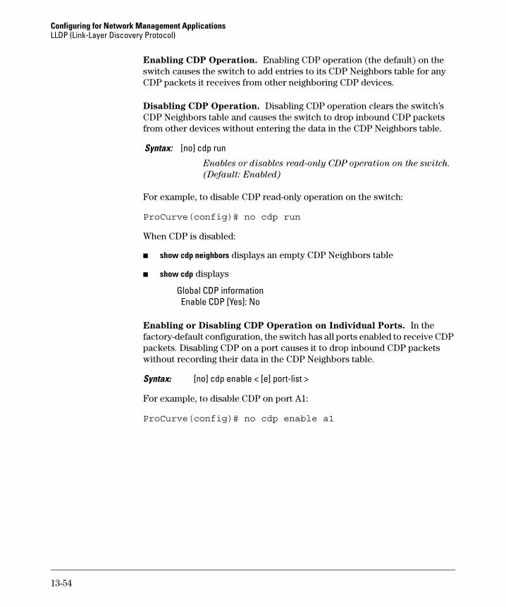
Configuring for Network Management Applications LLDP (Link-Layer Discovery Protocol)
Enabling CDP Operation. Enabling CDP operation (the default) on the switch causes the switch to add entries to its CDP Neighbors table for any CDP packets it receives from other neighboring CDP devices.
Disabling CDP Operation. Disabling CDP operation clears the switch’s CDP Neighbors table and causes the switch to drop inbound CDP packets from other devices without entering the data in the CDP Neighbors table.
Syntax: [no] cdp run
Enables or disables read-only CDP operation on the switch.
(Default: Enabled)
For example, to disable CDP read-only operation on the switch:
ProCurve(config)# no cdp run
When CDP is disabled:
■ show cdp neighbors displays an empty CDP Neighbors table
■ show cdp displays
Global CDP information Enable CDP [Yes]: No
Enabling or Disabling CDP Operation on Individual Ports. In the factory-default configuration, the switch has all ports enabled to receive CDP packets. Disabling CDP on a port causes it to drop inbound CDP packets without recording their data in the CDP Neighbors table.
Syntax: [no] cdp enable < [e] port-list >
For example, to disable CDP on port A1:
ProCurve(config)# no cdp enable a1
13-54
A
File Transfers
Contents
Overview . . . . . . . . . . . . . . . . . . . . . . . . . . . . . . . . . . . . . . . . . . . . . . . . . . . . . A-2
Downloading Switch Software . . . . . . . . . . . . . . . . . . . . . . . . . . . . . . . . . . . A-2
General Switch Software Download Rules . . . . . . . . . . . . . . . . . . . . . A-3
Using TFTP To Download Switch Software from a Server . . . . . . . . A-3Menu: TFTP Download from a Server to Primary Flash . . . . . . . A-4CLI: TFTP Download from a Server to Primary or Secondary Flash . . . . . . . . . . . . . . . . . . . . . . . . . . . . . . . . . . . . . . . . A-6
Using Secure Copy and SFTP
Using Xmodem to Download Switch Software From a PC or UNIX
. . . . . . . . . . . . . . . . . . . . . . . . . . . . . . . . A-7How It Works . . . . . . . . . . . . . . . . . . . . . . . . . . . . . . . . . . . . . . . . . . A-8The SCP/SFTP Process . . . . . . . . . . . . . . . . . . . . . . . . . . . . . . . . . . A-9Command Options . . . . . . . . . . . . . . . . . . . . . . . . . . . . . . . . . . . . . . A-9Authentication . . . . . . . . . . . . . . . . . . . . . . . . . . . . . . . . . . . . . . . . A-10SCP/SFTP Operating Notes . . . . . . . . . . . . . . . . . . . . . . . . . . . . . A-10
Workstation . . . . . . . . . . . . . . . . . . . . . . . . . . . . . . . . . . . . . . . . . . . . . . A-11Menu: Xmodem Download to Primary Flash . . . . . . . . . . . . . . . A-11CLI: Xmodem Download from a PC or Unix Workstation to Primary or Secondary Flash . . . . . . . . . . . . . . . . . . . . . . . . . . . A-12
Switch-to-Switch Download . . . . . . . . . . . . . . . . . . . . . . . . . . . . . . . . A-14Menu: Switch-to-Switch Download to Primary Flash . . . . . . . . A-14CLI: Switch-To-Switch Downloads . . . . . . . . . . . . . . . . . . . . . . . A-15
Using ProCurve Manager Plus to Update Switch Software . . . . . . . A-16
Troubleshooting TFTP Downloads . . . . . . . . . . . . . . . . . . . . . . . . . . . . . . A-17
Transferring Switch Configurations . . . . . . . . . . . . . . . . . . . . . . . . . . . . . . A-18
Copying Diagnostic Data to a Remote Host, PC, or Unix Workstation . A-21Copying Command Output to a Destination Device . . . . . . . . . A-21Copying Event Log Output to a Destination Device . . . . . . . . . A-22Copying Crash Data Content to a Destination Device . . . . . . . A-22Copying Crash Log Data Content to a Destination Device . . . . A-23
A-1
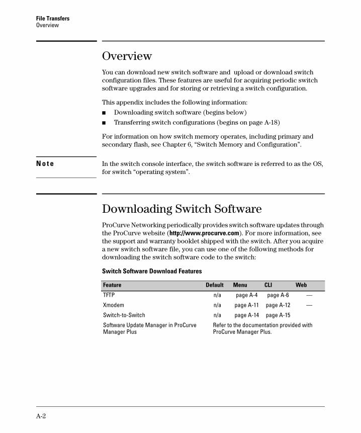
File Transfers Overview
Overview You can download new switch software and upload or download switch configuration files. These features are useful for acquiring periodic switch software upgrades and for storing or retrieving a switch configuration.
This appendix includes the following information:
■ Downloading switch software (begins below)
■ Transferring switch configurations (begins on page A-18)
For information on how switch memory operates, including primary and secondary flash, see Chapter 6, “Switch Memory and Configuration”.
N o t e In the switch console interface, the switch software is referred to as the OS, for switch “operating system”.
Downloading Switch Software ProCurve Networking periodically provides switch software updates through the ProCurve website (http://www.procurve.com). For more information, see the support and warranty booklet shipped with the switch. After you acquire a new switch software file, you can use one of the following methods for downloading the switch software code to the switch:
Switch Software Download Features
MenuFeature Default CLI Web
TFTP
Xmodem
Switch-to-Switch
Software Update Manager in ProCurve Manager Plus
n/a page A-4 page A-6 —
n/a page A-11 page A-12 —
n/a page A-14 page A-15
Refer to the documentation provided with ProCurve Manager Plus.
A-2
File Transfers Downloading Switch Software
General Switch Software Download Rules
■ A switch software image downloaded through the menu interface always goes to primary flash.
■ After a switch software download, you must reboot the switch to implement the newly downloaded code. Until a reboot occurs, the switch continues to run on the software it was using before the download started.
N o t e Downloading new switch software does not change the current switch configuration. The switch configuration is contained in separate files that can also be transferred. Refer to “Transferring Switch Configurations” on page A-18.
In most cases, if a power failure or other cause interrupts a flash image download, the switch reboots with the image previously stored in primary flash. In the unlikely event that the primary image is corrupted (which may occur if a download is interrupted by a power failure), the switch goes into boot ROM mode. In this case, use the boot ROM console to download a new switch software image to primary flash. Refer to “Restoring a Flash Image” on page C-44.
Using TFTP To Download Switch Software from a Server
This procedure assumes that:
■ An switch software file for the switch has been stored on a TFTP server accessible to the switch. (The switch software file is typically available from the ProCurve website at http://www.procurve.com.)
■ The switch is properly connected to your network and has already been configured with a compatible IP address and subnet mask.
■ The TFTP server is accessible to the switch through IP.
Before you use the procedure, do the following:
■ Obtain the IP address of the TFTP server in which the switch software file has been stored.
■ If VLANs are configured on the switch, determine the name of the VLAN in which the TFTP server is operating.
■ Determine the name of the switch software file stored in the TFTP server for the switch (for example, G0721.swi).
A-3
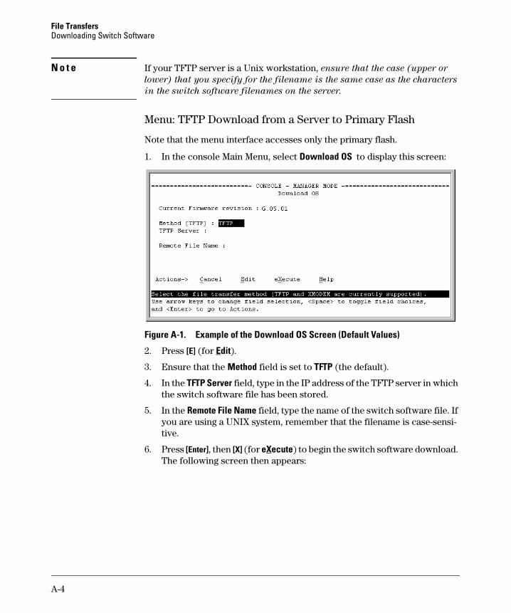
File Transfers Downloading Switch Software
N o t e If your TFTP server is a Unix workstation, ensure that the case (upper or
lower) that you specify for the filename is the same case as the characters
in the switch software filenames on the server.
Menu: TFTP Download from a Server to Primary Flash
Note that the menu interface accesses only the primary flash.
1. In the console Main Menu, select Download OS to display this screen:
Figure A-1. Example of the Download OS Screen (Default Values)
2. Press [E] (for Edit).
3. Ensure that the Method field is set to TFTP (the default).
4. In the TFTP Server field, type in the IP address of the TFTP server in which the switch software file has been stored.
5. In the Remote File Name field, type the name of the switch software file. If you are using a UNIX system, remember that the filename is case-sensi-tive.
6. Press [Enter], then [X] (for eXecute) to begin the switch software download. The following screen then appears:
A-4
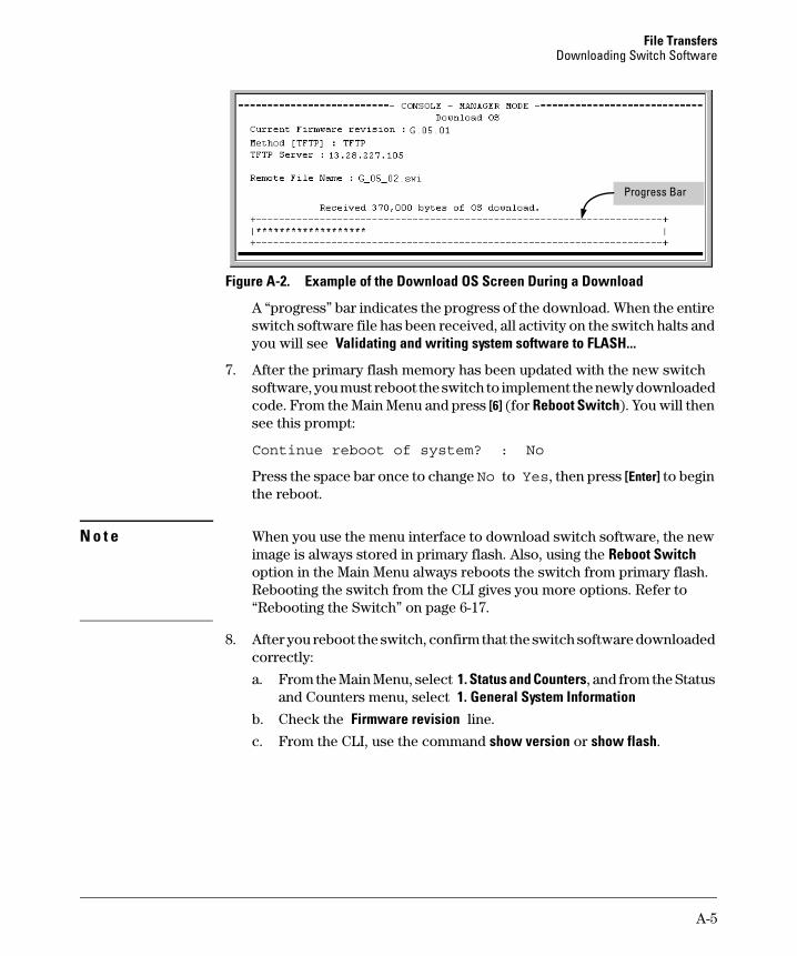
File Transfers Downloading Switch Software
Progress Bar
Figure A-2. Example of the Download OS Screen During a Download
A “progress” bar indicates the progress of the download. When the entire switch software file has been received, all activity on the switch halts and you will see Validating and writing system software to FLASH...
7. After the primary flash memory has been updated with the new switch software, you must reboot the switch to implement the newly downloaded code. From the Main Menu and press [6] (for Reboot Switch). You will then see this prompt:
Continue reboot of system? : No
Press the space bar once to change No to Yes, then press [Enter] to begin the reboot.
N o t e When you use the menu interface to download switch software, the new image is always stored in primary flash. Also, using the Reboot Switch option in the Main Menu always reboots the switch from primary flash. Rebooting the switch from the CLI gives you more options. Refer to “Rebooting the Switch” on page 6-17.
8. After you reboot the switch, confirm that the switch software downloaded correctly:
a. From the Main Menu, select 1. Status and Counters, and from the Status and Counters menu, select 1. General System Information
b. Check the Firmware revision line.
c. From the CLI, use the command show version or show flash.
A-5
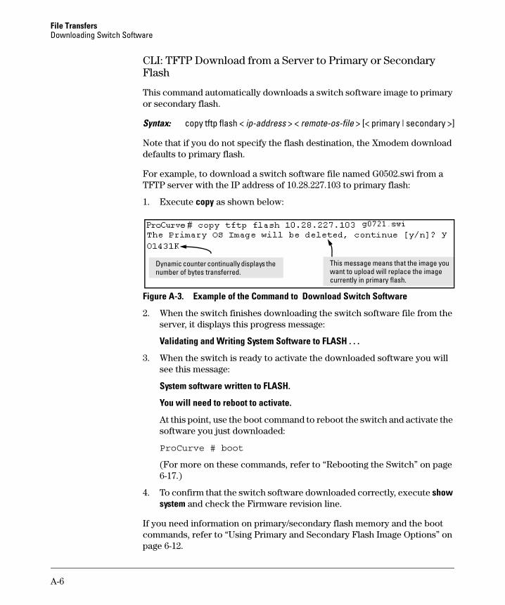
File Transfers Downloading Switch Software
CLI: TFTP Download from a Server to Primary or Secondary Flash
This command automatically downloads a switch software image to primary or secondary flash.
Syntax: copy tftp flash < ip-address > < remote-os-file > [< primary | secondary >]
Note that if you do not specify the flash destination, the Xmodem download defaults to primary flash.
For example, to download a switch software file named G0502.swi from a TFTP server with the IP address of 10.28.227.103 to primary flash:
1. Execute copy as shown below:
Dynamic counter continually displays the This message means that the image you number of bytes transferred. want to upload will replace the image
currently in primary flash.
Figure A-3. Example of the Command to Download Switch Software
2. When the switch finishes downloading the switch software file from the server, it displays this progress message:
Validating and Writing System Software to FLASH . . .
3. When the switch is ready to activate the downloaded software you will see this message:
System software written to FLASH.
You will need to reboot to activate.
At this point, use the boot command to reboot the switch and activate the software you just downloaded:
ProCurve # boot
(For more on these commands, refer to “Rebooting the Switch” on page 6-17.)
4. To confirm that the switch software downloaded correctly, execute show system and check the Firmware revision line.
If you need information on primary/secondary flash memory and the boot commands, refer to “Using Primary and Secondary Flash Image Options” on page 6-12.
A-6
File Transfers Downloading Switch Software
Using Secure Copy and SFTP
This feature is available only on the Series 2600, 2600-PWR, and 2800
Switches.
For some situations you may want to use a secure method to issue commands or copy files to the switch. By opening a secure, encrypted SSH session you can then use a third-party software application to take advantage of Secure Copy (SCP) and Secure ftp (SFTP). SCP and SFTP provide a secure alternative to TFTP for transferring information that may be sensitive (like switch configuration files) to and from the switch. Essentially you are creating a secure SSH tunnel as a way to transfer files with SFTP and SCP channels.
To use these commands you must install on the administrator workstation a third-party application software client that supports the SFTP and/or SCP functions. Some examples of software that supports SFTP and SCP are PuTTY, Open SSH, WinSCP, and SSH Secure Shell. Most of these are freeware and may be downloaded without cost or licensing from the internet. There are differences in the way these clients work, so be sure you also download the documentation.
As described earlier in this chapter you can use a TFTP client on the administrator workstation to update software images. This is a plain text mechanism and it connects to a standalone TFTP server or another ProCurve switch acting as a TFTP server to obtain the software image file(s). Using SCP and SFTP allows you to maintain your switches with greater security. You can also roll out new software images with automated scripts that make it easier to upgrade multiple switches simultaneously and securely.
SFTP (secure file transfer protocol) is unrelated to FTP, although there are some functional similarities. Once you set up an SFTP session through an SSH tunnel, some of the commands are the same as FTP commands. Certain commands are not allowed by the SFTP server on the switch, such as those that create files or folders. If you try to issue commands such as create or remove using SFTP the switch server returns an error message.
You can use SFTP just as you would TFTP to transfer files to and from the switch, but with SFTP your file transfers are encrypted and require authentication, so they are more secure than they would be using TFTP. SFTP works only with SSH version 2 (SSH v2).
A-7
File Transfers Downloading Switch Software
Note SFTP over SSH version 1 (SSH v1) is not supported. A request from either the client or the switch (or both) using SSH v1 generates an error message. The actual text of the error message differs, depending on the client software in use. Some examples are:
Protocol major versions differ: 2 vs. 1Connection closed
Protocol major versions differ: 1 vs. 2Connection closed
Received disconnect from < ip-addr >: /usr/local/ libexec/sftp-server: command not supported Connection closed
SCP (secure copy) is an implementation of the BSD rcp (Berkeley UNIX remote copy) command tunneled through an SSH connection.
SCP is used to copy files to and from the switch when security is required. SCP works with both SSH v1 and SSH v2. Be aware that the most third-party software application clients that support SCP use SSHv1.
How It Works
The general process for using SCP and SFTP involves three steps:
1. Open an SSH tunnel between your computer and the switch if you haven’t already done so. (This step assumes that you have already set up SSH on the switch.)
2. Execute ip ssh filetransfer to tell the switch that you want to enable secure file transfer.
3. Use a third-party client application for SCP and SFTP commands.
A-8
File Transfers Downloading Switch Software
The SCP/SFTP Process
To use SCP and SFTP:
1. Open an SSH session as you normally would to establish a secure encrypted tunnel between your computer and the switch. For more detailed directions on how to open an SSH session see the chapter titled “Configuring Secure Shell (SSH)” in the Access Security Guide for your switch. Please note that this is a one-time procedure for new switches or connections. If you have already done it once you should not need to do it a second time.
2. To enable secure file transfer on the switch (once you have an SSH session established between the switch and your computer), open a terminal window and type in the following command:
ProCurve(config)# ip ssh filetransfer
Command Options
If you need to enable SSH v2 (which is required for SFTP) enter this command:
ProCurve(config)# ip ssh version 2
Note As a matter of policy, administrators should not enable the SSHv1-only or the SSHv1-or-v2 advertisement modes. SSHv1 is supported on only some legacy switches (such as the ProCurve Series 2500 switches).
To confirm that SSH is enabled type in the command
ProCurve(config)# show ip ssh
3. Once you have confirmed that you have enabled an SSH session (with the show ip ssh command) you can then open your third-party software client application to begin using the SCP or SFTP commands to safely transfer files or issue commands to the switch.
If you need to disable secure file transfer:
ProCurve(config)# no ip ssh filetransfer
A-9
File Transfers Downloading Switch Software
Authentication
Switch memory allows up to ten public keys. This means the authentication and encryption keys you use for your third-party client SCP/SFTP software can differ from the keys you use for the SSH session, even though both SCP and SFTP use a secure SSH tunnel.
N o t e SSH authentication through a TACACS+ server and use of SCP or SFTP through an SSH tunnel are mutually exclusive. Thus, if the switch is configured to use TACACS+ for authenticating a secure Telnet SSH session on the switch, you cannot enable SCP or SFTP. Also, if SCP or SFTP is enabled on the switch, you cannot enable TACACS+ authentication for a secure Telnet SSH. The switch displays a message similar to the following if there is an attempt to configure either option when the other is already configured:
To provide username/password authentication on a switch providing SCP or SFTP support, use the switch’s local username/password facility. Otherwise, you can use the switch’s local public key for authentication.
Some clients such as PSCP (PuTTY SCP) automatically compare switch host keys for you. Other clients require you to manually copy and paste keys to the $HOME/.ssh/known_hosts file. Whatever SCP/SFTP software tool you use, after installing the client software you must verify that the switch host keys are available to the client.
Because the third-party software utilities you may use for SCP/SFTP vary, you should refer to the documentation provided with the utility you select before performing this process.
SCP/SFTP Operating Notes
■ When an SFTP client connects, the switch provides a file system displaying all of its available files and folders. No file or directory creation is permitted by the user. Files may only be uploaded or downloaded, according to the permissions mask. All of the necessary files the switch will need are already in place on the switch. You do not need to (nor can you create) new files.
■ The switch supports one SFTP session or one SCP session at a time.
A-10
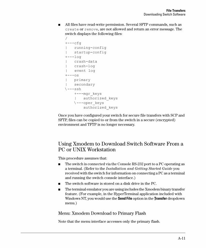
File Transfers Downloading Switch Software
■ All files have read-write permission. Several SFTP commands, such as create or remove, are not allowed and return an error message. The switch displays the following files: /+---cfg| running-config | startup-config +---log| crash-data | crash-log | event log+---os| primary | secondary \---ssh +---mgr_keys
| authorized_keys \---oper_keys
authorized_keys
Once you have configured your switch for secure file transfers with SCP and SFTP, files can be copied to or from the switch in a secure (encrypted) environment and TFTP is no longer necessary.
Using Xmodem to Download Switch Software From a PC or UNIX Workstation
This procedure assumes that:
■ The switch is connected via the Console RS-232 port to a PC operating as a terminal. (Refer to the Installation and Getting Started Guide you received with the switch for information on connecting a PC as a terminal and running the switch console interface.)
■ The switch software is stored on a disk drive in the PC.
■ The terminal emulator you are using includes the Xmodem binary transfer feature. (For example, in the HyperTerminal application included with Windows NT, you would use the Send File option in the Transfer dropdown menu.)
Menu: Xmodem Download to Primary Flash
Note that the menu interface accesses only the primary flash.
A-11
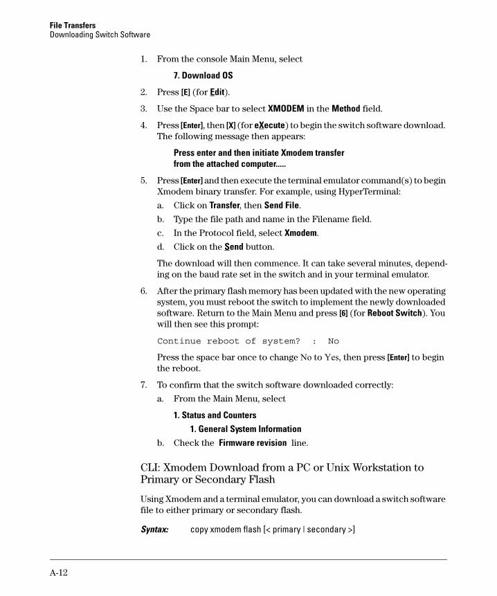
File Transfers Downloading Switch Software
1. From the console Main Menu, select
7. Download OS
2. Press [E] (for Edit).
3. Use the Space bar to select XMODEM in the Method field.
4. Press [Enter], then [X] (for eXecute) to begin the switch software download. The following message then appears:
Press enter and then initiate Xmodem transfer from the attached computer.....
5. Press [Enter] and then execute the terminal emulator command(s) to begin Xmodem binary transfer. For example, using HyperTerminal:
a. Click on Transfer, then Send File.
b. Type the file path and name in the Filename field.
c. In the Protocol field, select Xmodem.
d. Click on the Send button.
The download will then commence. It can take several minutes, depending on the baud rate set in the switch and in your terminal emulator.
6. After the primary flash memory has been updated with the new operating system, you must reboot the switch to implement the newly downloaded software. Return to the Main Menu and press [6] (for Reboot Switch). You will then see this prompt:
Continue reboot of system? : No
Press the space bar once to change No to Yes, then press [Enter] to begin the reboot.
7. To confirm that the switch software downloaded correctly:
a. From the Main Menu, select
1. Status and Counters 1. General System Information
b. Check the Firmware revision line.
CLI: Xmodem Download from a PC or Unix Workstation to Primary or Secondary Flash
Using Xmodem and a terminal emulator, you can download a switch software file to either primary or secondary flash.
Syntax: copy xmodem flash [< primary | secondary >]
A-12
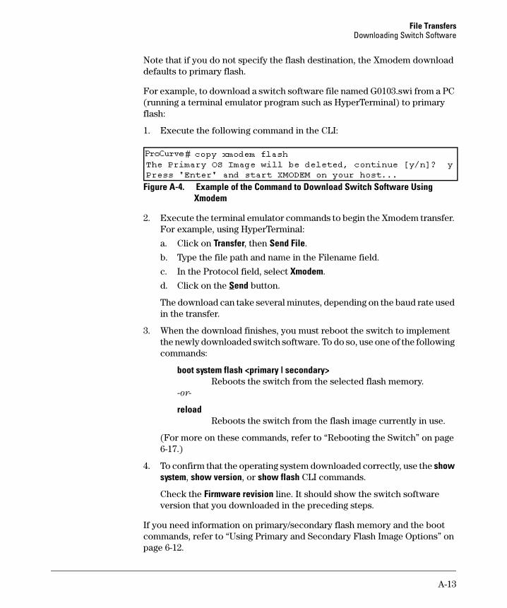
File Transfers Downloading Switch Software
Note that if you do not specify the flash destination, the Xmodem download defaults to primary flash.
For example, to download a switch software file named G0103.swi from a PC (running a terminal emulator program such as HyperTerminal) to primary flash:
1. Execute the following command in the CLI:
Figure A-4. Example of the Command to Download Switch Software Using Xmodem
2. Execute the terminal emulator commands to begin the Xmodem transfer. For example, using HyperTerminal:
a. Click on Transfer, then Send File.
b. Type the file path and name in the Filename field.
c. In the Protocol field, select Xmodem.
d. Click on the Send button.
The download can take several minutes, depending on the baud rate used in the transfer.
3. When the download finishes, you must reboot the switch to implement the newly downloaded switch software. To do so, use one of the following commands:
boot system flash <primary | secondary> Reboots the switch from the selected flash memory.
-or-
reload Reboots the switch from the flash image currently in use.
(For more on these commands, refer to “Rebooting the Switch” on page 6-17.)
4. To confirm that the operating system downloaded correctly, use the show system, show version, or show flash CLI commands.
Check the Firmware revision line. It should show the switch software version that you downloaded in the preceding steps.
If you need information on primary/secondary flash memory and the boot commands, refer to “Using Primary and Secondary Flash Image Options” on page 6-12.
A-13
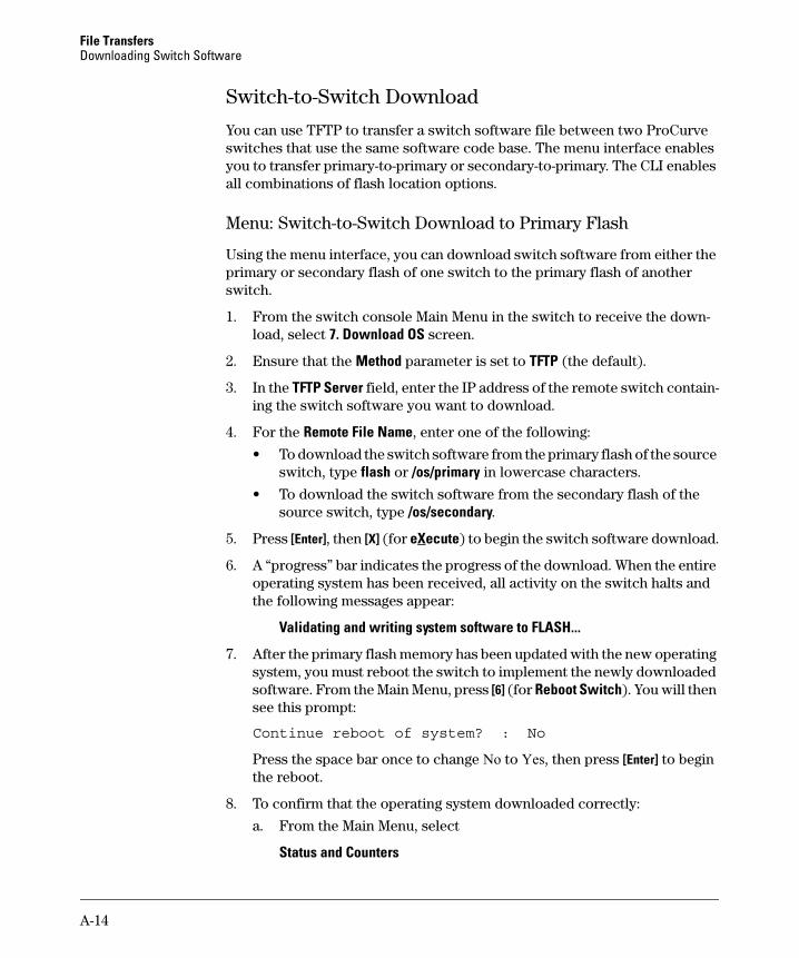
File Transfers Downloading Switch Software
Switch-to-Switch Download
You can use TFTP to transfer a switch software file between two ProCurve switches that use the same software code base. The menu interface enables you to transfer primary-to-primary or secondary-to-primary. The CLI enables all combinations of flash location options.
Menu: Switch-to-Switch Download to Primary Flash
Using the menu interface, you can download switch software from either the primary or secondary flash of one switch to the primary flash of another switch.
1. From the switch console Main Menu in the switch to receive the download, select 7. Download OS screen.
2. Ensure that the Method parameter is set to TFTP (the default).
3. In the TFTP Server field, enter the IP address of the remote switch containing the switch software you want to download.
4. For the Remote File Name, enter one of the following:
• To download the switch software from the primary flash of the source switch, type flash or /os/primary in lowercase characters.
• To download the switch software from the secondary flash of the source switch, type /os/secondary.
5. Press [Enter], then [X] (for eXecute) to begin the switch software download.
6. A “progress” bar indicates the progress of the download. When the entire operating system has been received, all activity on the switch halts and the following messages appear:
Validating and writing system software to FLASH...
7. After the primary flash memory has been updated with the new operating system, you must reboot the switch to implement the newly downloaded software. From the Main Menu, press [6] (for Reboot Switch). You will then see this prompt:
Continue reboot of system? : No
Press the space bar once to change No to Yes, then press [Enter] to begin the reboot.
8. To confirm that the operating system downloaded correctly:
a. From the Main Menu, select
Status and Counters
A-14
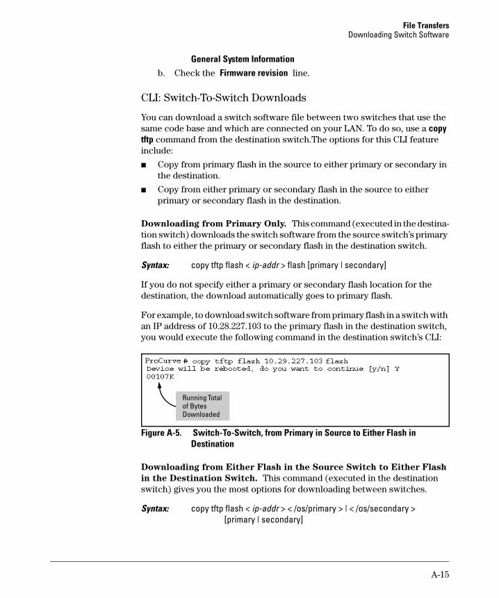
File Transfers Downloading Switch Software
General System Information b. Check the Firmware revision line.
CLI: Switch-To-Switch Downloads
You can download a switch software file between two switches that use the same code base and which are connected on your LAN. To do so, use a copy tftp command from the destination switch.The options for this CLI feature include:
■ Copy from primary flash in the source to either primary or secondary in the destination.
■ Copy from either primary or secondary flash in the source to either primary or secondary flash in the destination.
Downloading from Primary Only. This command (executed in the destination switch) downloads the switch software from the source switch’s primary flash to either the primary or secondary flash in the destination switch.
Syntax: copy tftp flash < ip-addr > flash [primary | secondary]
If you do not specify either a primary or secondary flash location for the destination, the download automatically goes to primary flash.
For example, to download switch software from primary flash in a switch with an IP address of 10.28.227.103 to the primary flash in the destination switch, you would execute the following command in the destination switch’s CLI:
of Bytes Running Total
Downloaded
Figure A-5. Switch-To-Switch, from Primary in Source to Either Flash in Destination
Downloading from Either Flash in the Source Switch to Either Flash
in the Destination Switch. This command (executed in the destination switch) gives you the most options for downloading between switches.
Syntax: copy tftp flash < ip-addr > < /os/primary > | < /os/secondary > [primary | secondary]
A-15
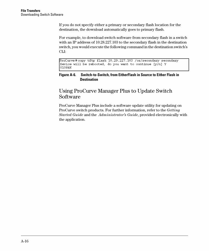
File Transfers Downloading Switch Software
If you do not specify either a primary or secondary flash location for the destination, the download automatically goes to primary flash.
For example, to download switch software from secondary flash in a switch with an IP address of 10.28.227.103 to the secondary flash in the destination switch, you would execute the following command in the destination switch’s CLI:
Figure A-6. Switch-to-Switch, from Either Flash in Source to Either Flash in Destination
Using ProCurve Manager Plus to Update Switch Software
ProCurve Manager Plus include a software update utility for updating on ProCurve switch products. For further information, refer to the Getting
Started Guide and the Administrator’s Guide, provided electronically with the application.
A-16
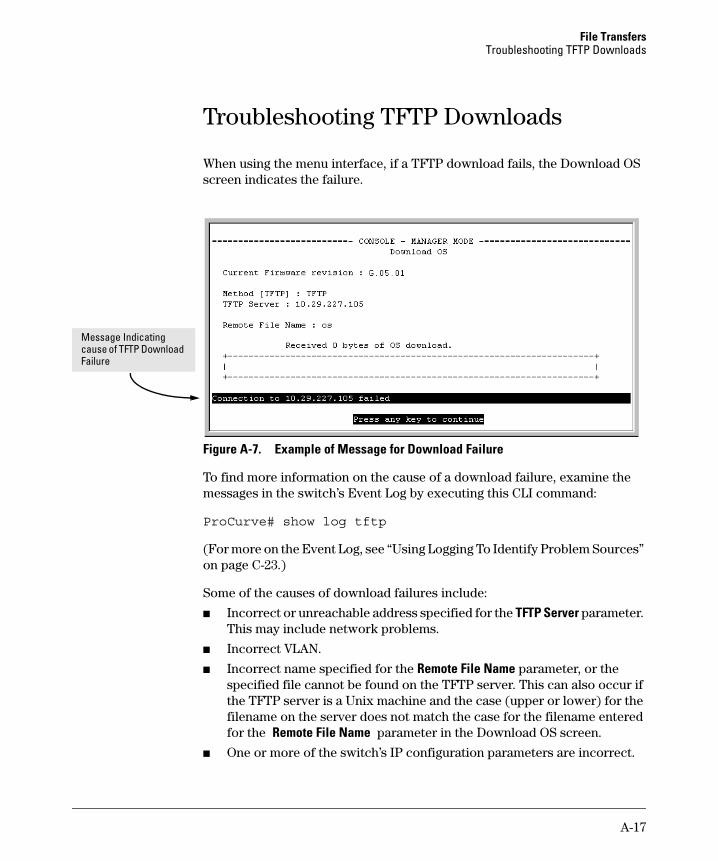
File Transfers Troubleshooting TFTP Downloads
Troubleshooting TFTP Downloads
When using the menu interface, if a TFTP download fails, the Download OS screen indicates the failure.
Message Indicating cause of TFTP Download Failure
Figure A-7. Example of Message for Download Failure
To find more information on the cause of a download failure, examine the messages in the switch’s Event Log by executing this CLI command:
ProCurve# show log tftp
(For more on the Event Log, see “Using Logging To Identify Problem Sources” on page C-23.)
Some of the causes of download failures include:
■ Incorrect or unreachable address specified for the TFTP Server parameter. This may include network problems.
■ Incorrect VLAN.
■ Incorrect name specified for the Remote File Name parameter, or the specified file cannot be found on the TFTP server. This can also occur if the TFTP server is a Unix machine and the case (upper or lower) for the filename on the server does not match the case for the filename entered for the Remote File Name parameter in the Download OS screen.
■ One or more of the switch’s IP configuration parameters are incorrect.
A-17
File Transfers Transferring Switch Configurations
■ For a Unix TFTP server, the file permissions for the switch software file do not allow the file to be copied.
■ Another console session (through either a direct connection to a terminal device or through Telnet) was already running when you started the session in which the download was attempted.
N o t e If an error occurs in which normal switch operation cannot be restored, the switch automatically reboots itself. In this case, an appropriate message is displayed after the switch reboots.
Transferring Switch Configurations
Transfer Features
Feature Default Menu CLI Web
use TFTP to copy from a remote n/a — below —host to a config file
use TFTP to copy a config file to a n/a — page A-19 —remote host
use Xmodem to copy a n/a — page A-19 —configuration from a serially connected host to a config file
Use Xmodem to copy a config file n/a — page A-20 —to a serially connected host
Using the CLI commands described in this section, you can copy switch configurations to and from a switch.
TFTP: Copying a Configuration from a Remote Host.
Syntax: copy tftp < startup-config | running-config>< ip-address > < remote-file >
This command copies a configuration from a remote host to the startup-config file in the switch. (Refer to Chapter 6, “Switch Memory and Configuration” for information on the startup-config file.)
For example, to download a configuration file named sw4100 in the configs directory on drive "d" in a remote host having an IP address of 10.28.227.105:
ProCurve# copy tftp startup-config 10.28.227.105 d:\configs\sw4100
A-18
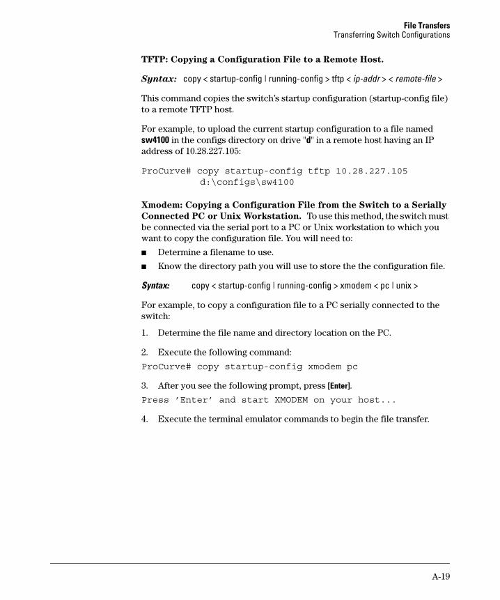
File Transfers Transferring Switch Configurations
TFTP: Copying a Configuration File to a Remote Host.
Syntax: copy < startup-config | running-config > tftp < ip-addr > < remote-file >
This command copies the switch’s startup configuration (startup-config file) to a remote TFTP host.
For example, to upload the current startup configuration to a file named sw4100 in the configs directory on drive "d" in a remote host having an IP address of 10.28.227.105:
ProCurve# copy startup-config tftp 10.28.227.105 d:\configs\sw4100
Xmodem: Copying a Configuration File from the Switch to a Serially
Connected PC or Unix Workstation. To use this method, the switch must be connected via the serial port to a PC or Unix workstation to which you want to copy the configuration file. You will need to:
■ Determine a filename to use.
■ Know the directory path you will use to store the the configuration file.
Syntax: copy < startup-config | running-config > xmodem < pc | unix >
For example, to copy a configuration file to a PC serially connected to the switch:
1. Determine the file name and directory location on the PC.
2. Execute the following command:
ProCurve# copy startup-config xmodem pc
3. After you see the following prompt, press [Enter].
Press ’Enter’ and start XMODEM on your host...
4. Execute the terminal emulator commands to begin the file transfer.
A-19
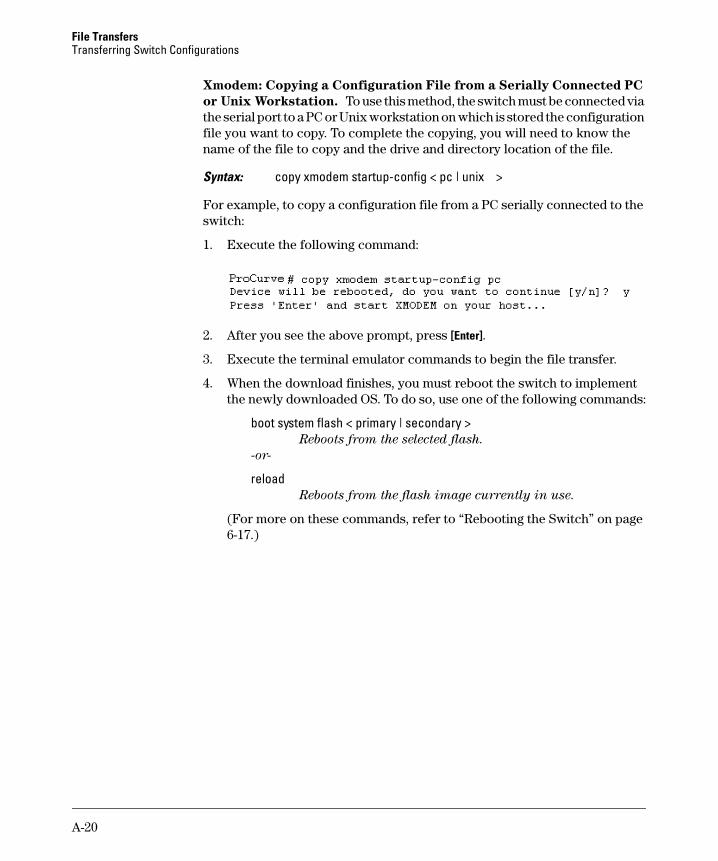
File Transfers Transferring Switch Configurations
Xmodem: Copying a Configuration File from a Serially Connected PC
or Unix Workstation. To use this method, the switch must be connected via the serial port to a PC or Unix workstation on which is stored the configuration file you want to copy. To complete the copying, you will need to know the name of the file to copy and the drive and directory location of the file.
Syntax: copy xmodem startup-config < pc | unix >
For example, to copy a configuration file from a PC serially connected to the switch:
1. Execute the following command:
2. After you see the above prompt, press [Enter].
3. Execute the terminal emulator commands to begin the file transfer.
4. When the download finishes, you must reboot the switch to implement the newly downloaded OS. To do so, use one of the following commands:
boot system flash < primary | secondary > Reboots from the selected flash.
-or-
reload Reboots from the flash image currently in use.
(For more on these commands, refer to “Rebooting the Switch” on page 6-17.)
A-20
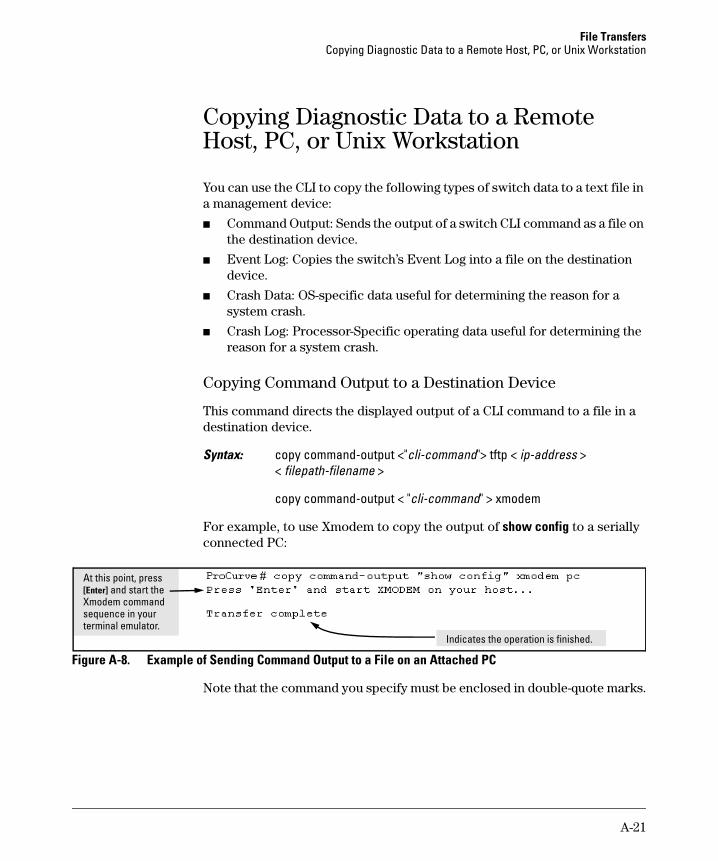
File Transfers Copying Diagnostic Data to a Remote Host, PC, or Unix Workstation
Copying Diagnostic Data to a Remote Host, PC, or Unix Workstation
You can use the CLI to copy the following types of switch data to a text file in a management device:
■ Command Output: Sends the output of a switch CLI command as a file on the destination device.
■ Event Log: Copies the switch’s Event Log into a file on the destination device.
■ Crash Data: OS-specific data useful for determining the reason for a system crash.
■ Crash Log: Processor-Specific operating data useful for determining the reason for a system crash.
Copying Command Output to a Destination Device
This command directs the displayed output of a CLI command to a file in a destination device.
Syntax: copy command-output <"cli-command"> tftp < ip-address > < filepath-filename >
copy command-output < "cli-command" > xmodem
For example, to use Xmodem to copy the output of show config to a serially connected PC:
i
l
At this po nt, press [Enter] and start the Xmodem command sequence in your termina emulator.
Indicates the operation is finished.
Figure A-8. Example of Sending Command Output to a File on an Attached PC
Note that the command you specify must be enclosed in double-quote marks.
A-21
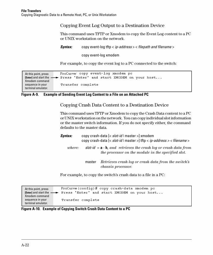
File Transfers Copying Diagnostic Data to a Remote Host, PC, or Unix Workstation
Copying Event Log Output to a Destination Device
This command uses TFTP or Xmodem to copy the Event Log content to a PC or UNIX workstation on the network.
Syntax: copy event-log tftp < ip-address > < filepath and filename >
copy event-log xmodem
For example, to copy the event log to a PC connected to the switch:
At this point, press [Enter] and start the Xmodem command sequence in your terminal emulator.
Figure A-9. Example of Sending Event Log Content to a File on an Attached PC
Copying Crash Data Content to a Destination Device
This command uses TFTP or Xmodem to copy the Crash Data content to a PC or UNIX workstation on the network. You can copy individual slot information or the master switch information. If you do not specify either, the command defaults to the master data.
Syntax: copy crash-data [< slot-id | master >] xmodem copy crash-data [< slot-id | master >] tftp < ip-address > < filename >
where: slot-id = a - h, and retrieves the crash log or crash data from
the processor on the module in the specified slot.
master Retrieves crash log or crash data from the switch’s
chassis processor.
For example, to copy the switch’s crash data to a file in a PC:
At this point, press [Enter] and start the Xmodem command sequence in your terminal emulator.
Figure A-10. Example of Copying Switch Crash Data Content to a PC
A-22
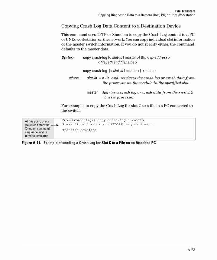
File Transfers Copying Diagnostic Data to a Remote Host, PC, or Unix Workstation
Copying Crash Log Data Content to a Destination Device
This command uses TFTP or Xmodem to copy the Crash Log content to a PC or UNIX workstation on the network. You can copy individual slot information or the master switch information. If you do not specify either, the command defaults to the master data.
Syntax: copy crash-log [< slot-id | master >] tftp < ip-address > < filepath and filename >
copy crash-log [< slot-id | master >] xmodem
where: slot-id = a - h, and retrieves the crash log or crash data from
the processor on the module in the specified slot.
master Retrieves crash log or crash data from the switch’s
chassis processor.
For example, to copy the Crash Log for slot C to a file in a PC connected to the switch:
At this point, press [Enter] and start the Xmodem command sequence in your terminal emulator.
Figure A-11. Example of sending a Crash Log for Slot C to a File on an Attached PC
A-23

File Transfers Copying Diagnostic Data to a Remote Host, PC, or Unix Workstation
— This page is intentionally unused. —
A-24
B
Monitoring and Analyzing Switch Operation
Contents
Overview . . . . . . . . . . . . . . . . . . . . . . . . . . . . . . . . . . . . . . . . . . . . . . . . . . . . . B-3
Status and Counters Data . . . . . . . . . . . . . . . . . . . . . . . . . . . . . . . . . . . . . . . B-4
Menu Access To Status and Counters . . . . . . . . . . . . . . . . . . . . . . . . . B-5
General System Information . . . . . . . . . . . . . . . . . . . . . . . . . . . . . . . . . B-6Menu Access . . . . . . . . . . . . . . . . . . . . . . . . . . . . . . . . . . . . . . . . . . . B-6CLI Access . . . . . . . . . . . . . . . . . . . . . . . . . . . . . . . . . . . . . . . . . . . . . B-6
Switch Management Address Information . . . . . . . . . . . . . . . . . . . . . . B-7Menu Access . . . . . . . . . . . . . . . . . . . . . . . . . . . . . . . . . . . . . . . . . . . B-7CLI Access . . . . . . . . . . . . . . . . . . . . . . . . . . . . . . . . . . . . . . . . . . . . . B-7
Module Information . . . . . . . . . . . . . . . . . . . . . . . . . . . . . . . . . . . . . . . . B-8Menu: Displaying Port Status . . . . . . . . . . . . . . . . . . . . . . . . . . . . . B-8CLI Access . . . . . . . . . . . . . . . . . . . . . . . . . . . . . . . . . . . . . . . . . . . . . B-8
Port Status . . . . . . . . . . . . . . . . . . . . . . . . . . . . . . . . . . . . . . . . . . . . . . . . B-9Menu: Displaying Port Status . . . . . . . . . . . . . . . . . . . . . . . . . . . . . B-9CLI Access . . . . . . . . . . . . . . . . . . . . . . . . . . . . . . . . . . . . . . . . . . . . . B-9Web Access . . . . . . . . . . . . . . . . . . . . . . . . . . . . . . . . . . . . . . . . . . . . B-9
Viewing Port and Trunk Group Statistics and Flow Control Status B-10Menu Access to Port and Trunk Statistics . . . . . . . . . . . . . . . . . B-11CLI Access To Port and Trunk Group Statistics . . . . . . . . . . . . B-12Web Browser Access To View Port and Trunk Group Statistics B-12
Viewing the Switch’s MAC Address Tables . . . . . . . . . . . . . . . . . . . . B-13Menu Access to the MAC Address Views and Searches . . . . . . B-14CLI Access for MAC Address Views and Searches . . . . . . . . . . B-16
Spanning Tree Protocol (STP) Information . . . . . . . . . . . . . . . . . . . . B-18Menu Access to STP Data . . . . . . . . . . . . . . . . . . . . . . . . . . . . . . . B-18CLI Access to STP Data . . . . . . . . . . . . . . . . . . . . . . . . . . . . . . . . . B-19
Internet Group Management Protocol (IGMP) Status . . . . . . . . . . . B-20
VLAN Information . . . . . . . . . . . . . . . . . . . . . . . . . . . . . . . . . . . . . . . . . B-21
Web Browser Interface Status Information . . . . . . . . . . . . . . . . . . . . B-23
Port and Static Trunk Monitoring Features . . . . . . . . . . . . . . . . . . . . . . . B-24
B-1
Monitoring and Analyzing Switch Operation Contents
Switch 6108 and Series 4100gl Switches . . . . . . . . . . . . . . . . . . . . . . B-24
Series 2600, 2600-PWR, and 2800 Switches . . . . . . . . . . . . . . . . . . . . B-24
Menu: Configuring Port and Static Trunk Monitoring . . . . . . . . . . . B-25
CLI: Configuring Port and Static Trunk Monitoring . . . . . . . . . . . . . B-27
Web: Configuring Port Monitoring . . . . . . . . . . . . . . . . . . . . . . . . . . . B-29
B-2
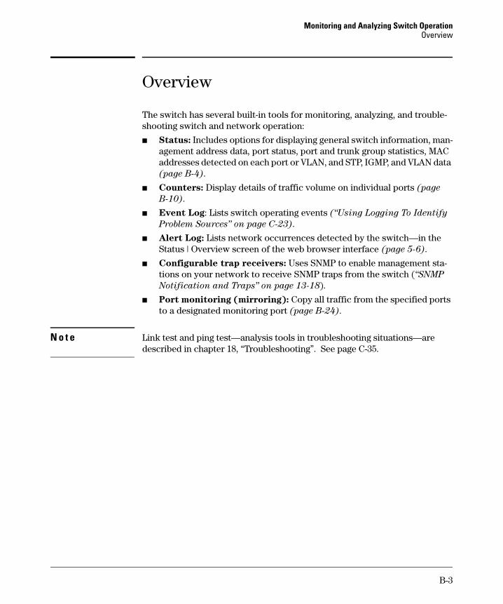
Monitoring and Analyzing Switch Operation Overview
Overview
The switch has several built-in tools for monitoring, analyzing, and troubleshooting switch and network operation:
■ Status: Includes options for displaying general switch information, management address data, port status, port and trunk group statistics, MAC addresses detected on each port or VLAN, and STP, IGMP, and VLAN data (page B-4).
■ Counters: Display details of traffic volume on individual ports (page
B-10).
■ Event Log: Lists switch operating events (“Using Logging To Identify
Problem Sources” on page C-23).
■ Alert Log: Lists network occurrences detected by the switch—in the Status | Overview screen of the web browser interface (page 5-6).
■ Configurable trap receivers: Uses SNMP to enable management stations on your network to receive SNMP traps from the switch (“SNMP
Notification and Traps” on page 13-18).
■ Port monitoring (mirroring): Copy all traffic from the specified ports to a designated monitoring port (page B-24).
N o t e Link test and ping test—analysis tools in troubleshooting situations—are described in chapter 18, “Troubleshooting”. See page C-35.
B-3
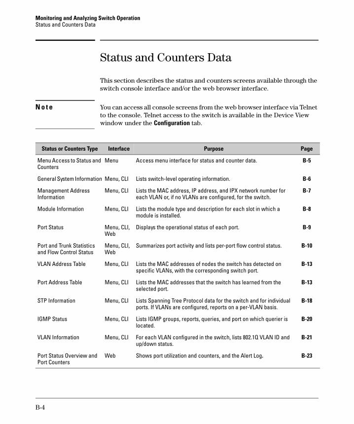
Monitoring and Analyzing Switch Operation Status and Counters Data
Status and Counters Data
This section describes the status and counters screens available through the switch console interface and/or the web browser interface.
N o t e You can access all console screens from the web browser interface via Telnet to the console. Telnet access to the switch is available in the Device View window under the Configuration tab.
Interface PageStatus or Counters Type Purpose
Menu Access to Status and Menu Counters
General System Information Menu, CLI
Management Address Information
Module Information
Port Status
Port and Trunk Statistics and Flow Control Status
VLAN Address Table
Port Address Table
STP Information
IGMP Status
VLAN Information
Port Status Overview and Port Counters
Menu, CLI
Menu, CLI
Menu, CLI, Web
Menu, CLI, Web
Menu, CLI
Menu, CLI
Menu, CLI
Menu, CLI
Menu, CLI
Web
Access menu interface for status and counter data. B-5
Lists switch-level operating information. B-6
Lists the MAC address, IP address, and IPX network number for B-7 each VLAN or, if no VLANs are configured, for the switch.
Lists the module type and description for each slot in which a B-8 module is installed.
Displays the operational status of each port. B-9
Summarizes port activity and lists per-port flow control status. B-10
Lists the MAC addresses of nodes the switch has detected on B-13 specific VLANs, with the corresponding switch port.
Lists the MAC addresses that the switch has learned from the B-13 selected port.
Lists Spanning Tree Protocol data for the switch and for individual B-18 ports. If VLANs are configured, reports on a per-VLAN basis.
Lists IGMP groups, reports, queries, and port on which querier is B-20 located.
For each VLAN configured in the switch, lists 802.1Q VLAN ID and B-21 up/down status.
Shows port utilization and counters, and the Alert Log. B-23
B-4
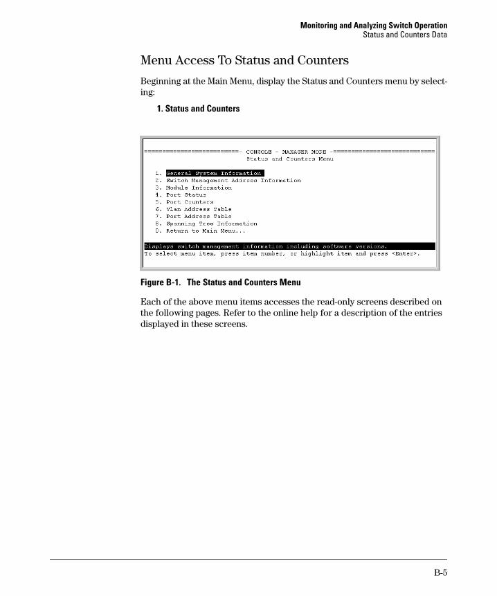
Monitoring and Analyzing Switch Operation Status and Counters Data
Menu Access To Status and Counters
Beginning at the Main Menu, display the Status and Counters menu by selecting:
1. Status and Counters
Figure B-1. The Status and Counters Menu
Each of the above menu items accesses the read-only screens described on the following pages. Refer to the online help for a description of the entries displayed in these screens.
B-5
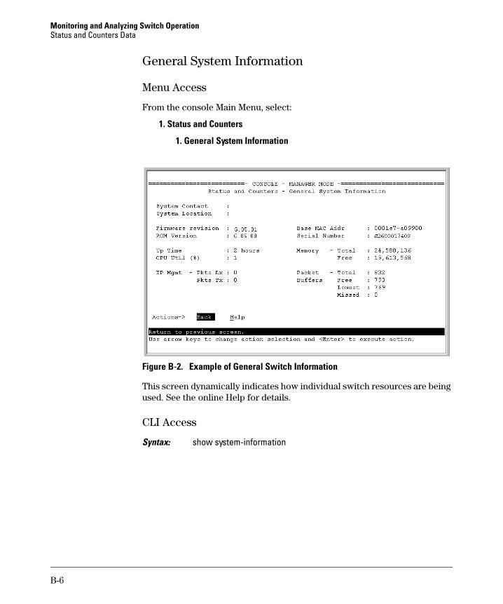
Monitoring and Analyzing Switch Operation Status and Counters Data
General System Information
Menu Access
From the console Main Menu, select:
1. Status and Counters
1. General System Information
Figure B-2. Example of General Switch Information
This screen dynamically indicates how individual switch resources are being used. See the online Help for details.
CLI Access
Syntax: show system-information
B-6
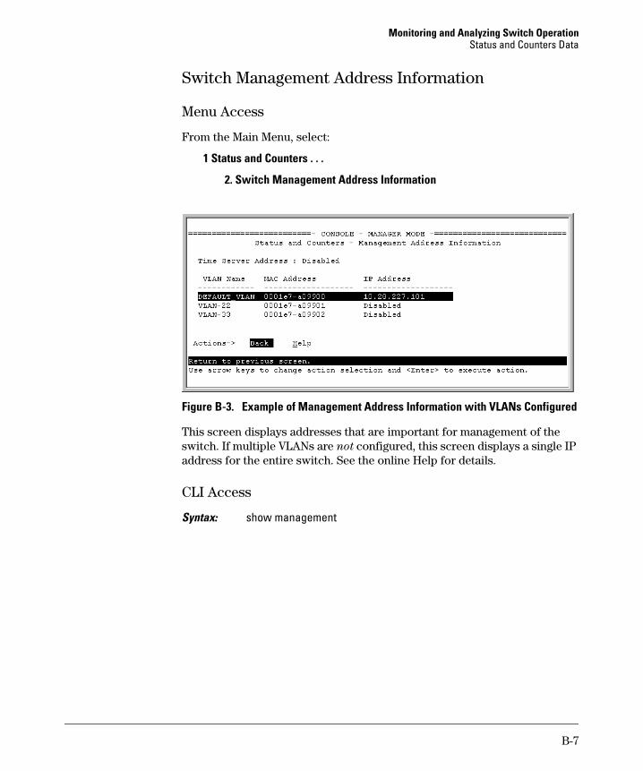
Monitoring and Analyzing Switch Operation Status and Counters Data
Switch Management Address Information
Menu Access
From the Main Menu, select:
1 Status and Counters . . .
2. Switch Management Address Information
Figure B-3. Example of Management Address Information with VLANs Configured
This screen displays addresses that are important for management of the switch. If multiple VLANs are not configured, this screen displays a single IP address for the entire switch. See the online Help for details.
CLI Access
Syntax: show management
B-7
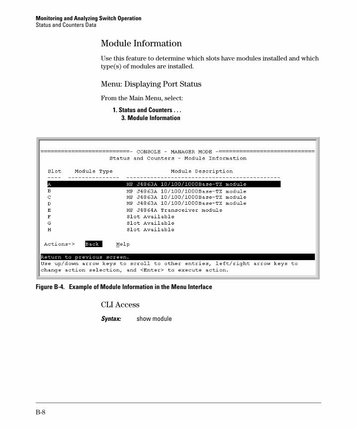
Monitoring and Analyzing Switch Operation Status and Counters Data
Module Information
Use this feature to determine which slots have modules installed and which type(s) of modules are installed.
Menu: Displaying Port Status
From the Main Menu, select:
1. Status and Counters . . . 3. Module Information
Figure B-4. Example of Module Information in the Menu Interface
CLI Access
Syntax: show module
B-8
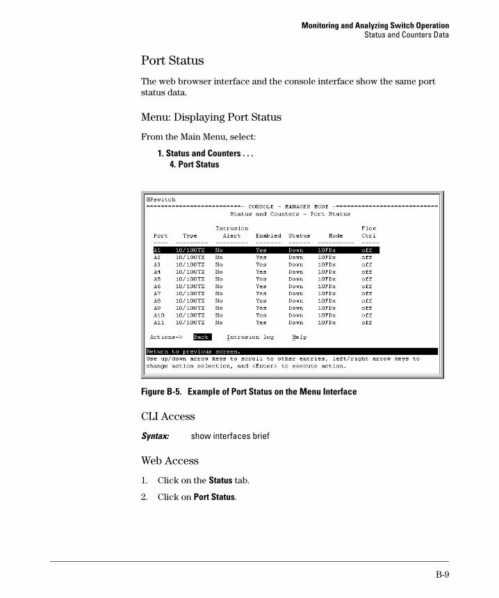
Monitoring and Analyzing Switch Operation Status and Counters Data
Port Status
The web browser interface and the console interface show the same port status data.
Menu: Displaying Port Status
From the Main Menu, select:
1. Status and Counters . . . 4. Port Status
Figure B-5. Example of Port Status on the Menu Interface
CLI Access
Syntax: show interfaces brief
Web Access
1. Click on the Status tab.
2. Click on Port Status.
B-9
Monitoring and Analyzing Switch Operation Status and Counters Data
Viewing Port and Trunk Group Statistics and Flow Control Status
Feature MenuDefault CLI Web
viewing port and trunk statistics for all n/a page B-11 page B-12 page B-12 ports, and flow control status
viewing a detailed summary for a n/a page B-11 page B-12 page B-12 particular port or trunk
resetting counters n/a page B-11 page B-12 page B-12
These features enable you to determine the traffic patterns for each port since the last reboot or reset of the switch. You can display:
■ A general report of traffic on all LAN ports and trunk groups in the switch, along with the per-port flow control status (On or Off).
■ A detailed summary of traffic on a selected port or trunk group.
You can also reset the counters for a specific port.
The menu interface and the web browser interface provide a dynamic display of counters summarizing the traffic on each port. The CLI lets you see a static “snapshot” of port or trunk group statistics at a particular moment.
As mentioned above, rebooting or resetting the switch resets the counters to zero. You can also reset the counters to zero for the current session. This is useful for troubleshooting. See the “Note On Reset”, below.
N o t e o n R e s e t The Reset action resets the counter display to zero for the current session, but does not affect the cumulative values in the actual hardware counters. (In compliance with the SNMP standard, the values in the hardware counters are not reset to zero unless you reboot the switch.) Thus, using the Reset action resets the displayed counters to zero for the current session only. Exiting from the console session and starting a new session restores the counter displays to the accumulated values in the hardware counters.
B-10
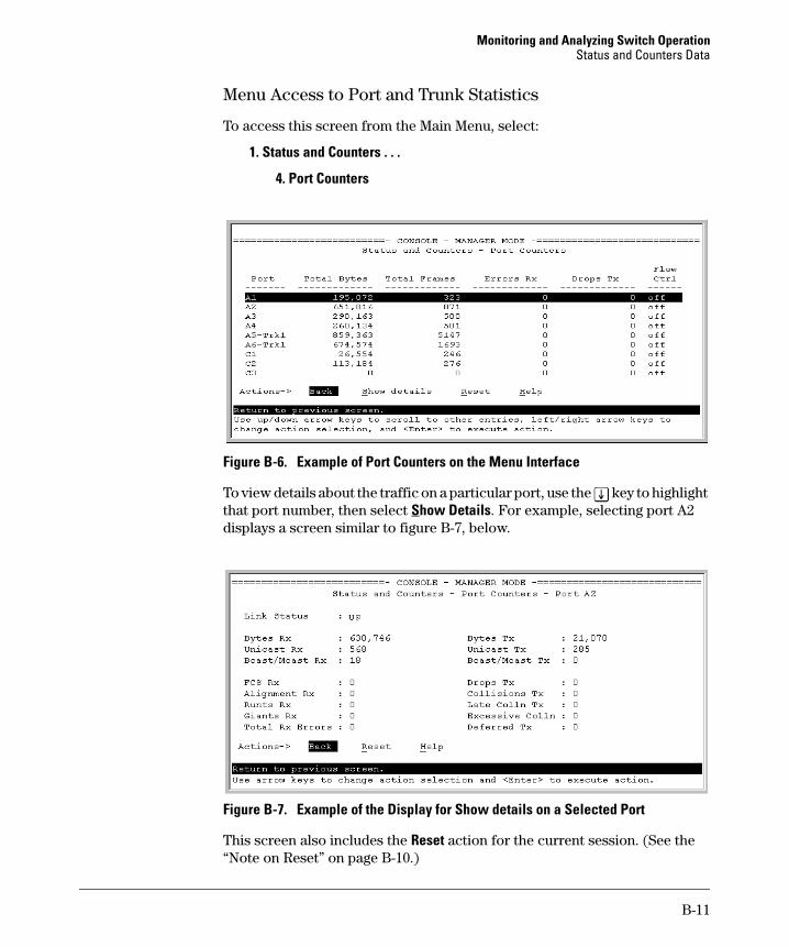
Monitoring and Analyzing Switch Operation Status and Counters Data
Menu Access to Port and Trunk Statistics
To access this screen from the Main Menu, select:
1. Status and Counters . . .
4. Port Counters
Figure B-6. Example of Port Counters on the Menu Interface
To view details about the traffic on a particular port, use the [v] key to highlight that port number, then select Show Details. For example, selecting port A2 displays a screen similar to figure B-7, below.
Figure B-7. Example of the Display for Show details on a Selected Port
This screen also includes the Reset action for the current session. (See the “Note on Reset” on page B-10.)
B-11

Monitoring and Analyzing Switch Operation Status and Counters Data
CLI Access To Port and Trunk Group Statistics
To Display the Port Counter Summary Report. This command provides an overview of port activity for all ports on the switch.
Syntax: show interfaces
To Display a Detailed Traffic Summary for Specific Ports. This command provides traffic details for the port(s) you specify.
Syntax: show interfaces [ethernet] < port-list >
To Reset the Port Counters for a Specific Port. This command resets the counters for the specified ports to zero for the current session. (See the “Note on Reset” on page B-10.)
Syntax: clear statistics < [ethernet] port-list >
Web Browser Access To View Port and Trunk Group Statistics
1. Click on the Status tab.
2. Click on Port Counters.
3. To reset the counters for a specific port, click anywhere in the row for that port, then click on Refresh.
B-12
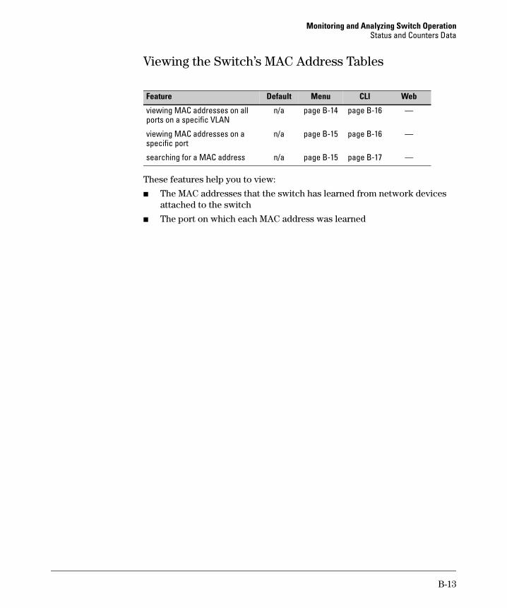
Monitoring and Analyzing Switch Operation Status and Counters Data
Viewing the Switch’s MAC Address Tables
Feature Default Menu CLI Web
viewing MAC addresses on all n/a page B-14 page B-16 — ports on a specific VLAN
viewing MAC addresses on a n/a page B-15 page B-16 — specific port
searching for a MAC address n/a page B-15 page B-17 —
These features help you to view:
■ The MAC addresses that the switch has learned from network devices attached to the switch
■ The port on which each MAC address was learned
B-13
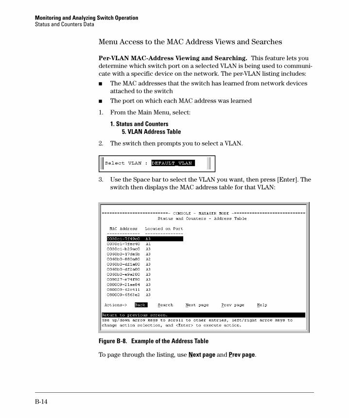
Monitoring and Analyzing Switch Operation Status and Counters Data
Menu Access to the MAC Address Views and Searches
Per-VLAN MAC-Address Viewing and Searching. This feature lets you determine which switch port on a selected VLAN is being used to communicate with a specific device on the network. The per-VLAN listing includes:
■ The MAC addresses that the switch has learned from network devices attached to the switch
■ The port on which each MAC address was learned
1. From the Main Menu, select:
1. Status and Counters 5. VLAN Address Table
2. The switch then prompts you to select a VLAN.
3. Use the Space bar to select the VLAN you want, then press [Enter]. The switch then displays the MAC address table for that VLAN:
Figure B-8. Example of the Address Table
To page through the listing, use Next page and Prev page.
B-14
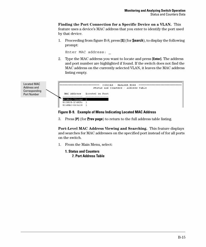
Monitoring and Analyzing Switch Operation Status and Counters Data
Finding the Port Connection for a Specific Device on a VLAN. This feature uses a device’s MAC address that you enter to identify the port used by that device.
1. Proceeding from figure B-8, press [S] (for Search), to display the following prompt:
Enter MAC address: _
2. Type the MAC address you want to locate and press [Enter]. The address and port number are highlighted if found. If the switch does not find the MAC address on the currently selected VLAN, it leaves the MAC address listing empty.
Located MAC Address and Corresponding Port Number
Figure B-9. Example of Menu Indicating Located MAC Address
3. Press [P] (for Prev page) to return to the full address table listing.
Port-Level MAC Address Viewing and Searching. This feature displays and searches for MAC addresses on the specified port instead of for all ports on the switch.
1. From the Main Menu, select:
1. Status and Counters 7. Port Address Table
B-15
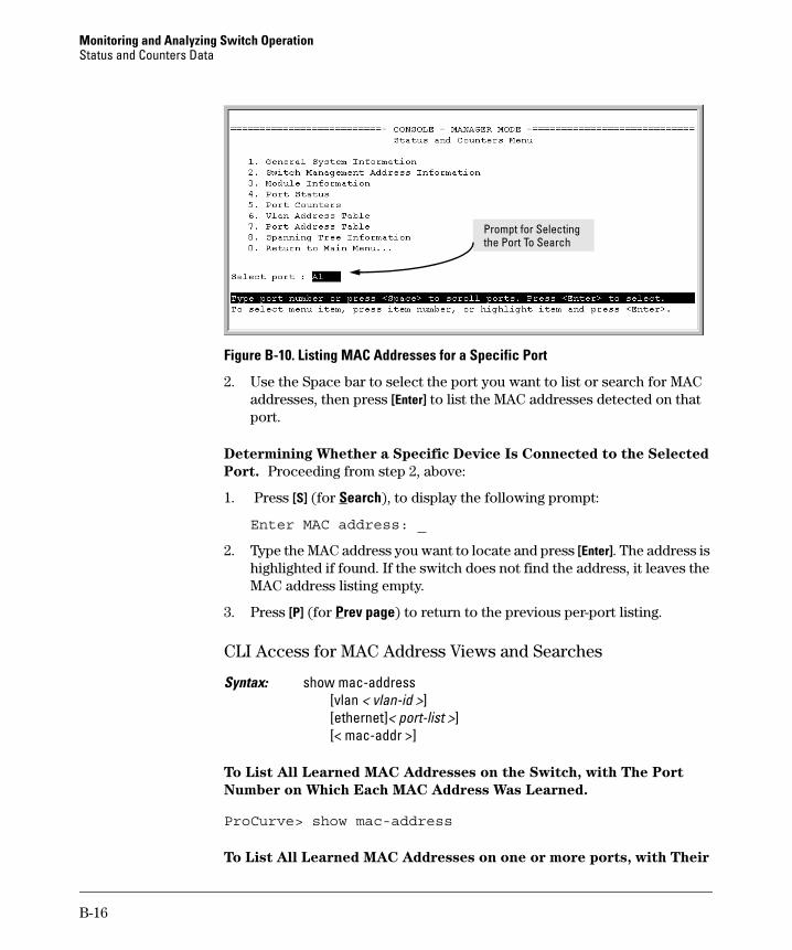
Monitoring and Analyzing Switch Operation Status and Counters Data
Prompt for Selecting the Port To Search
Figure B-10. Listing MAC Addresses for a Specific Port
2. Use the Space bar to select the port you want to list or search for MAC addresses, then press [Enter] to list the MAC addresses detected on that port.
Determining Whether a Specific Device Is Connected to the Selected
Port. Proceeding from step 2, above:
1. Press [S] (for Search), to display the following prompt:
Enter MAC address: _
2. Type the MAC address you want to locate and press [Enter]. The address is highlighted if found. If the switch does not find the address, it leaves the MAC address listing empty.
3. Press [P] (for Prev page) to return to the previous per-port listing.
CLI Access for MAC Address Views and Searches
Syntax: show mac-address [vlan < vlan-id >] [ethernet]< port-list >] [< mac-addr >]
To List All Learned MAC Addresses on the Switch, with The Port
Number on Which Each MAC Address Was Learned.
ProCurve> show mac-address
To List All Learned MAC Addresses on one or more ports, with Their
B-16
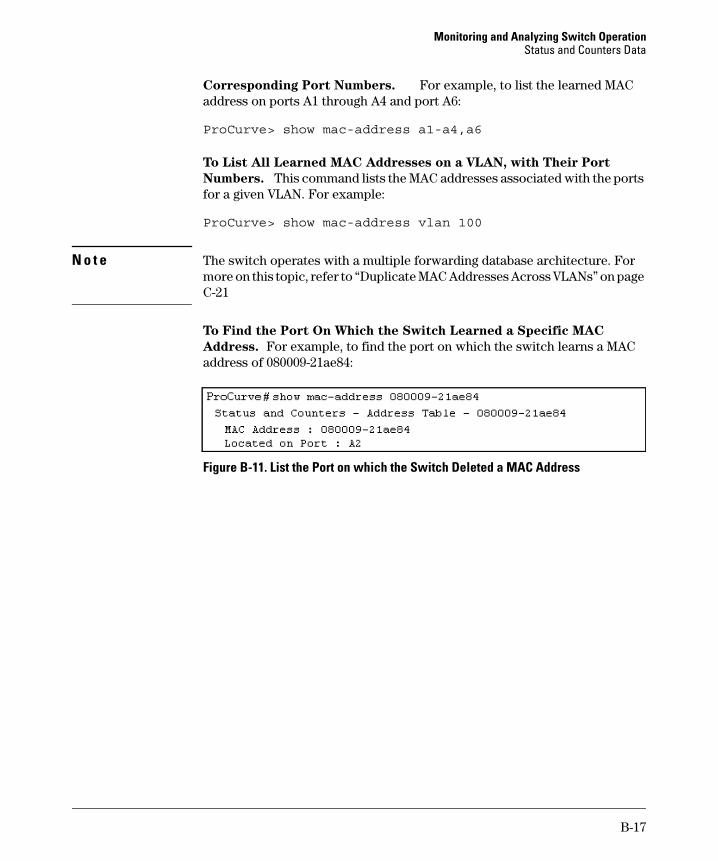
Monitoring and Analyzing Switch Operation Status and Counters Data
Corresponding Port Numbers. For example, to list the learned MAC address on ports A1 through A4 and port A6:
ProCurve> show mac-address a1-a4,a6
To List All Learned MAC Addresses on a VLAN, with Their Port
Numbers. This command lists the MAC addresses associated with the ports for a given VLAN. For example:
ProCurve> show mac-address vlan 100
N o t e The switch operates with a multiple forwarding database architecture. For more on this topic, refer to “Duplicate MAC Addresses Across VLANs” on page C-21
To Find the Port On Which the Switch Learned a Specific MAC
Address. For example, to find the port on which the switch learns a MAC address of 080009-21ae84:
Figure B-11. List the Port on which the Switch Deleted a MAC Address
B-17
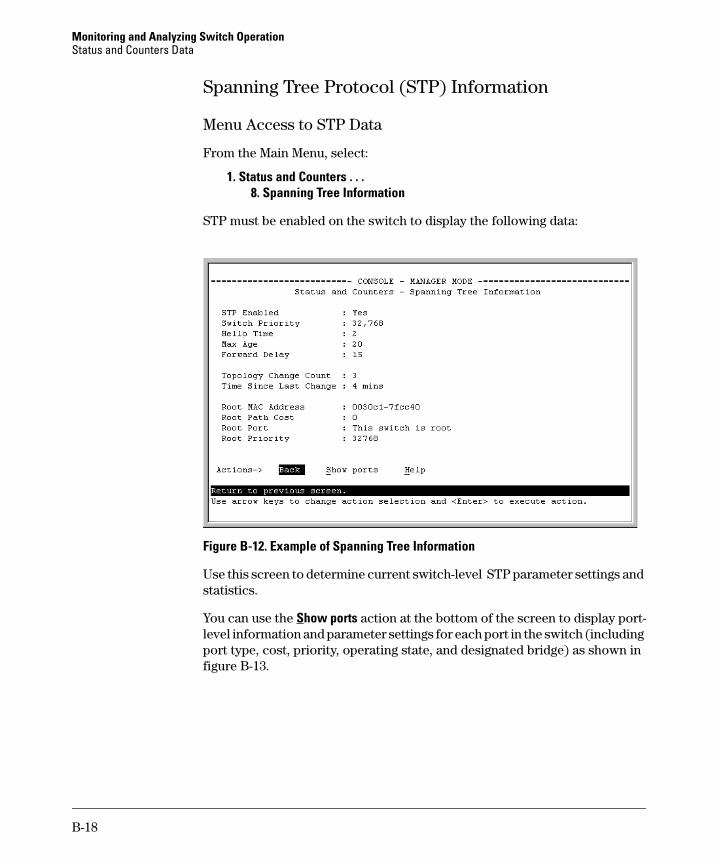
Monitoring and Analyzing Switch Operation Status and Counters Data
Spanning Tree Protocol (STP) Information
Menu Access to STP Data
From the Main Menu, select:
1. Status and Counters . . . 8. Spanning Tree Information
STP must be enabled on the switch to display the following data:
Figure B-12. Example of Spanning Tree Information
Use this screen to determine current switch-level STP parameter settings and statistics.
You can use the Show ports action at the bottom of the screen to display port-level information and parameter settings for each port in the switch (including port type, cost, priority, operating state, and designated bridge) as shown in figure B-13.
B-18
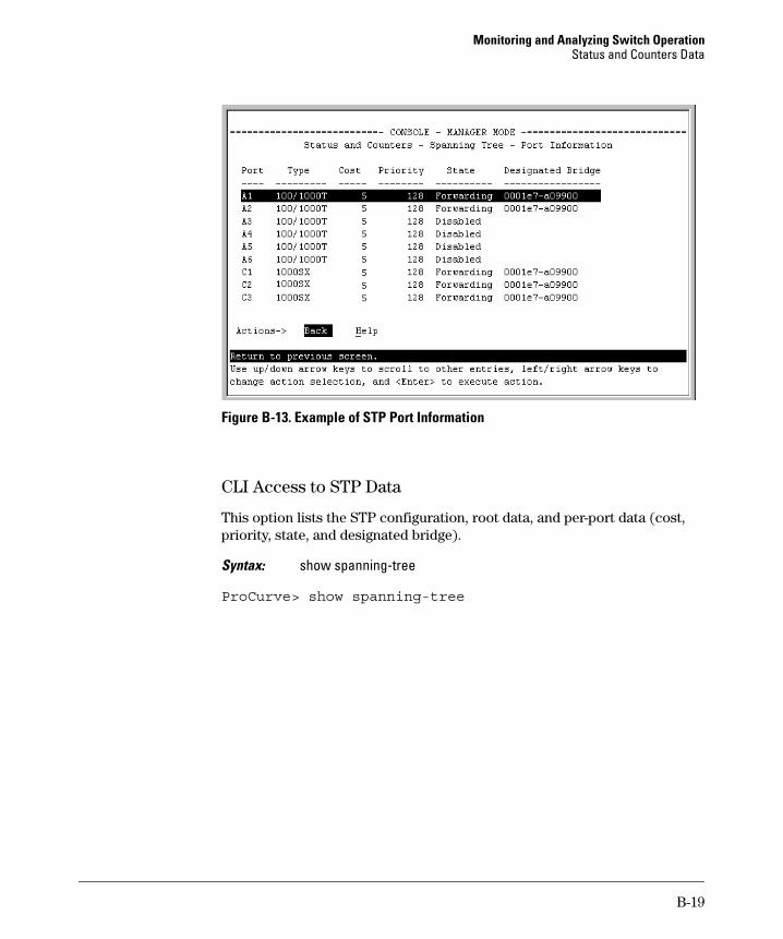
Monitoring and Analyzing Switch Operation Status and Counters Data
Figure B-13. Example of STP Port Information
CLI Access to STP Data
This option lists the STP configuration, root data, and per-port data (cost, priority, state, and designated bridge).
Syntax: show spanning-tree
ProCurve> show spanning-tree
B-19
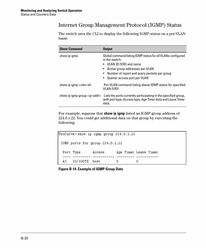
Monitoring and Analyzing Switch Operation Status and Counters Data
Internet Group Management Protocol (IGMP) Status
The switch uses the CLI to display the following IGMP status on a per-VLAN basis:
Show Command Output
show ip igmp Global command listing IGMP status for all VLANs configured in the switch: • VLAN ID (VID) and name • Active group addresses per VLAN • Number of report and query packets per group • Querier access port per VLAN
show ip igmp <vlan-id> Per-VLAN command listing above IGMP status for specified VLAN (VID)
show ip igmp group <ip-addr> Lists the ports currently participating in the specified group, with port type, Access type, Age Timer data and Leave Timer data.
For example, suppose that show ip igmp listed an IGMP group address of 224.0.1.22. You could get additional data on that group by executing the following:
Figure B-14. Example of IGMP Group Data
B-20
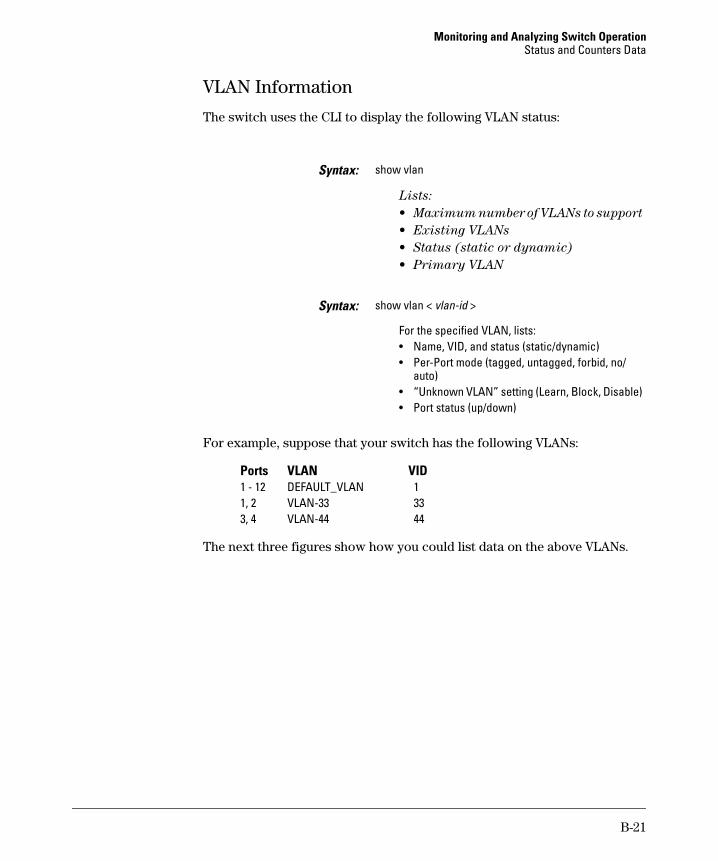
Monitoring and Analyzing Switch Operation Status and Counters Data
VLAN Information
The switch uses the CLI to display the following VLAN status:
Syntax: show vlan
Lists:
• Maximum number of VLANs to support
• Existing VLANs
• Status (static or dynamic)
• Primary VLAN
Syntax: show vlan < vlan-id >
For the specified VLAN, lists: • Name, VID, and status (static/dynamic) • Per-Port mode (tagged, untagged, forbid, no/
auto) • “Unknown VLAN” setting (Learn, Block, Disable) • Port status (up/down)
For example, suppose that your switch has the following VLANs:
Ports VLAN VID 1 - 12 DEFAULT_VLAN 11, 2 VLAN-33 333, 4 VLAN-44 44
The next three figures show how you could list data on the above VLANs.
B-21
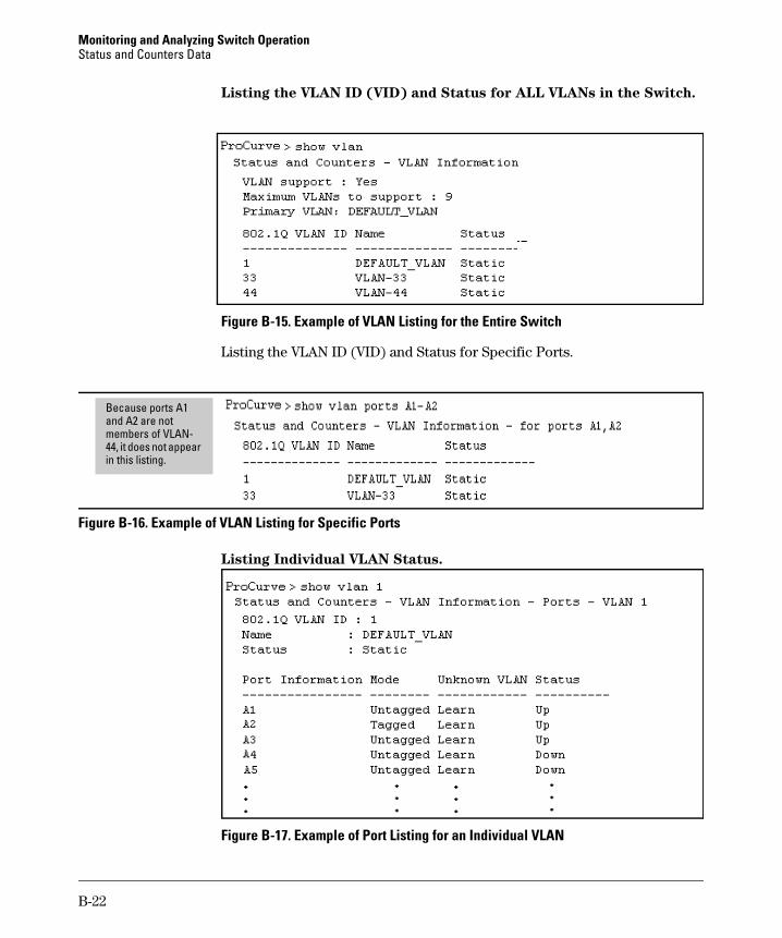
Monitoring and Analyzing Switch Operation Status and Counters Data
Listing the VLAN ID (VID) and Status for ALL VLANs in the Switch.
Figure B-15. Example of VLAN Listing for the Entire Switch
Listing the VLAN ID (VID) and Status for Specific Ports.
44, ii li
Because ports A1 and A2 are not members of VLAN
t does not appear n this sting.
Figure B-16. Example of VLAN Listing for Specific Ports
Listing Individual VLAN Status.
Figure B-17. Example of Port Listing for an Individual VLAN
B-22
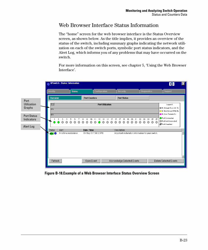
Monitoring and Analyzing Switch Operation Status and Counters Data
Web Browser Interface Status Information
The “home” screen for the web browser interface is the Status Overview screen, as shown below. As the title implies, it provides an overview of the status of the switch, including summary graphs indicating the network utilization on each of the switch ports, symbolic port status indicators, and the Alert Log, which informs you of any problems that may have occurred on the switch.
For more information on this screen, see chapter 5, ‘Using the Web Browser Interface’.
Port
Port Status
Utilization Graphs
Indicators
Alert Log
Figure B-18.Example of a Web Browser Interface Status Overview Screen
B-23
Monitoring and Analyzing Switch Operation Port and Static Trunk Monitoring Features
Port and Static Trunk Monitoring Features
Port Monitoring Features
Feature Default Menu CLI Web
display monitoring disabled configuration
configure the monitor port(s) ports: none
selecting or removing ports none selected
page B-25 page B-27 page B-29
page B-25 page B-27 page B-29
page B-25 page B-28 page B-29
Switch 6108 and Series 4100gl Switches
You can designate a port for monitoring inbound (ingress) traffic of other ports and of static trunks on the switch. The switch monitors the network activity by copying all traffic inbound on the specified interfaces to the designated monitoring port, to which a network analyzer can be attached.
Series 2600, 2600-PWR, and 2800 Switches
You can designate a port for monitoring inbound (ingress) and outbound (egress) traffic of other ports and of static trunks on the switch. The switch monitors the network activity by copying all inbound and outbound traffic on the specified interfaces to the designated monitoring port, to which a network analyzer can be attached.
All 2600 Series models will support inbound and outbound port monitoring. However, the 2650 and 2650-PWR require that the “mirror port” be within the same grouping as the monitored ports. On the 2650/2650-PWR switches, ports are grouped as follows: 1-24 + 49, and 25-48 + 50. These groupings represent the connections of ports to NetSwitch ASICs within the models.
The instructions below apply to all of the switches covered in this manual.
N o t e Port trunks cannot be used as a monitoring port.
It is possible, when monitoring multiple interfaces in networks with high traffic levels, to copy more traffic to a monitor port than the link can support. In this case, some packets may not be copied to the monitor port.
B-24
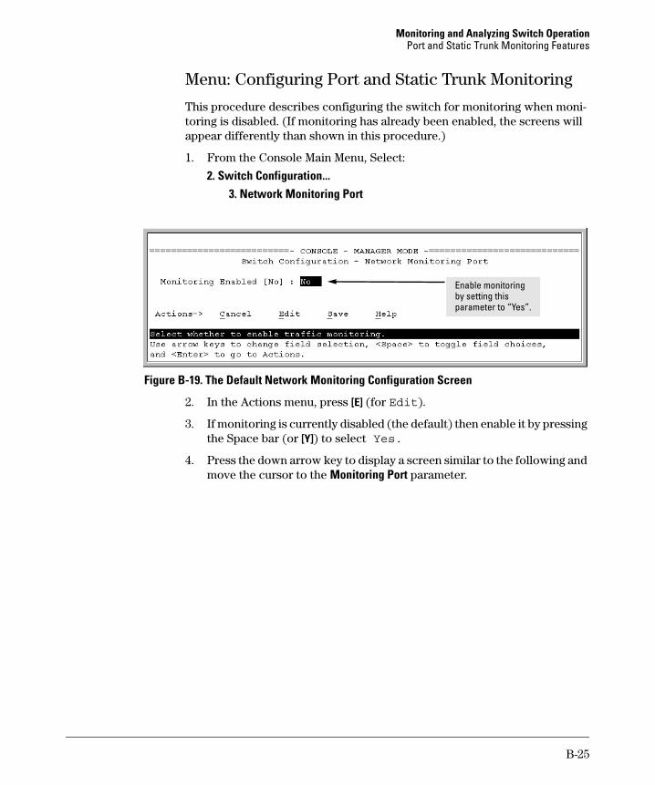
Monitoring and Analyzing Switch Operation Port and Static Trunk Monitoring Features
Menu: Configuring Port and Static Trunk Monitoring
This procedure describes configuring the switch for monitoring when monitoring is disabled. (If monitoring has already been enabled, the screens will appear differently than shown in this procedure.)
1. From the Console Main Menu, Select:
2. Switch Configuration... 3. Network Monitoring Port
ingEnable monitorby setting this parameter to “Yes”.
Figure B-19. The Default Network Monitoring Configuration Screen
2. In the Actions menu, press [E] (for Edit).
3. If monitoring is currently disabled (the default) then enable it by pressing the Space bar (or [Y]) to select Yes.
4. Press the down arrow key to display a screen similar to the following and move the cursor to the Monitoring Port parameter.
B-25
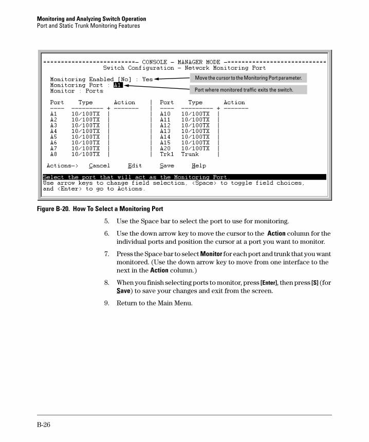
Monitoring and Analyzing Switch Operation Port and Static Trunk Monitoring Features
iMove the cursor to the Mon toring Port parameter.
Port where monitored traffic exits the switch.
Figure B-20. How To Select a Monitoring Port
5. Use the Space bar to select the port to use for monitoring.
6. Use the down arrow key to move the cursor to the Action column for the individual ports and position the cursor at a port you want to monitor.
7. Press the Space bar to select Monitor for each port and trunk that you want monitored. (Use the down arrow key to move from one interface to the next in the Action column.)
8. When you finish selecting ports to monitor, press [Enter], then press [S] (for Save) to save your changes and exit from the screen.
9. Return to the Main Menu.
B-26
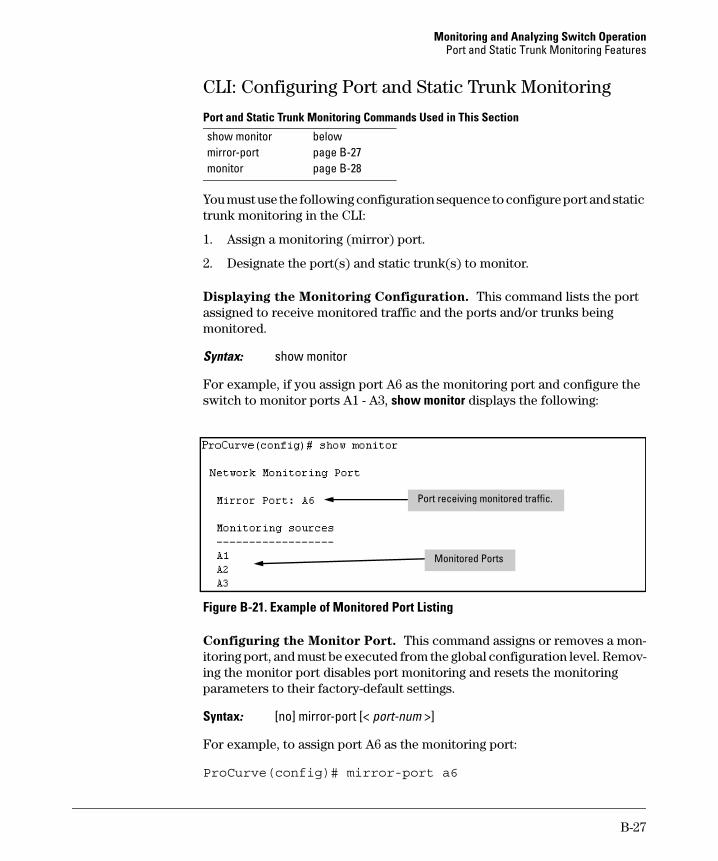
Monitoring and Analyzing Switch Operation Port and Static Trunk Monitoring Features
CLI: Configuring Port and Static Trunk Monitoring
Port and Static Trunk Monitoring Commands Used in This Section
show monitor below mirror-port page B-27 monitor page B-28
You must use the following configuration sequence to configure port and static trunk monitoring in the CLI:
1. Assign a monitoring (mirror) port.
2. Designate the port(s) and static trunk(s) to monitor.
Displaying the Monitoring Configuration. This command lists the port assigned to receive monitored traffic and the ports and/or trunks being monitored.
Syntax: show monitor
For example, if you assign port A6 as the monitoring port and configure the switch to monitor ports A1 - A3, show monitor displays the following:
Port receiving monitored traffic.
Monitored Ports
Figure B-21. Example of Monitored Port Listing
Configuring the Monitor Port. This command assigns or removes a monitoring port, and must be executed from the global configuration level. Removing the monitor port disables port monitoring and resets the monitoring parameters to their factory-default settings.
Syntax: [no] mirror-port [< port-num >]
For example, to assign port A6 as the monitoring port:
ProCurve(config)# mirror-port a6
B-27
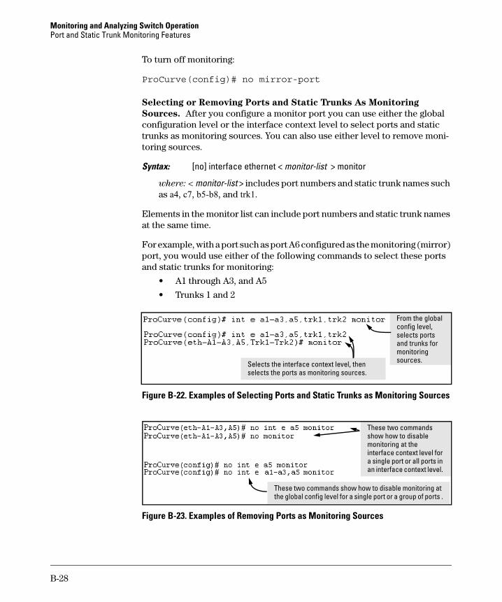
Monitoring and Analyzing Switch Operation Port and Static Trunk Monitoring Features
To turn off monitoring:
ProCurve(config)# no mirror-port
Selecting or Removing Ports and Static Trunks As Monitoring
Sources. After you configure a monitor port you can use either the global configuration level or the interface context level to select ports and static trunks as monitoring sources. You can also use either level to remove monitoring sources.
Syntax: [no] interface ethernet < monitor-list > monitor
where: < monitor-list > includes port numbers and static trunk names such as a4, c7, b5-b8, and trk1.
Elements in the monitor list can include port numbers and static trunk names at the same time.
For example, with a port such as port A6 configured as the monitoring (mirror) port, you would use either of the following commands to select these ports and static trunks for monitoring:
• A1 through A3, and A5
• Trunks 1 and 2
From the global config level,
moni
itori
selects ports and trunks for
toring sources. Selects the interface context level, then
selects the ports as mon ng sources.
Figure B-22. Examples of Selecting Ports and Static Trunks as Monitoring Sources
These two commands show how to disable monitoring at the interface context level for a single port or all ports in an interface context level.
These two commands show how to disable monitoring at the global config level for a single port or a group of ports .
Figure B-23. Examples of Removing Ports as Monitoring Sources
B-28

Monitoring and Analyzing Switch Operation Port and Static Trunk Monitoring Features
Web: Configuring Port Monitoring
To enable port monitoring:
1. Click on the Configuration tab.
2. Click on Monitor Port.
3. To monitor one or more ports.
a. Click on the radio button for Monitor Selected Ports. b. Select the port(s) to monitor.
4. Click on Apply Changes.
To remove port monitoring:
1. Click on the Monitoring Off radio button.
2. Click on Apply Changes.
For web-based Help on how to use the web browser interface screen, click on the [?] button provided on the web browser screen.
B-29

Monitoring and Analyzing Switch Operation Port and Static Trunk Monitoring Features
— This page is intentionally unused. —
B-30
C
Troubleshooting
Contents Overview . . . . . . . . . . . . . . . . . . . . . . . . . . . . . . . . . . . . . . . . . . . . . . . . . . . . . C-3
Troubleshooting Approaches . . . . . . . . . . . . . . . . . . . . . . . . . . . . . . . . . . . . C-3
Chassis Over-Temperature Detection . . . . . . . . . . . . . . . . . . . . . . . . . . . . . C-5
Browser or Telnet Access Problems . . . . . . . . . . . . . . . . . . . . . . . . . . . . . . C-6
Unusual Network Activity . . . . . . . . . . . . . . . . . . . . . . . . . . . . . . . . . . . . . . . C-8
General Problems . . . . . . . . . . . . . . . . . . . . . . . . . . . . . . . . . . . . . . . . . . C-8
Prioritization Problems . . . . . . . . . . . . . . . . . . . . . . . . . . . . . . . . . . . . . C-9
CDP Problems . . . . . . . . . . . . . . . . . . . . . . . . . . . . . . . . . . . . . . . . . . . . . C-9
IGMP-Related Problems . . . . . . . . . . . . . . . . . . . . . . . . . . . . . . . . . . . . C-10
LACP-Related Problems . . . . . . . . . . . . . . . . . . . . . . . . . . . . . . . . . . . . C-11
Port-Based Access Control (802.1X)-Related Problems . . . . . . . . . C-11
Radius-Related Problems . . . . . . . . . . . . . . . . . . . . . . . . . . . . . . . . . . . C-14
Spanning-Tree Protocol (STP) and Fast-Uplink Problems . . . . . . . C-15
SSH-Related Problems . . . . . . . . . . . . . . . . . . . . . . . . . . . . . . . . . . . . . C-16
Stacking-Related Problems . . . . . . . . . . . . . . . . . . . . . . . . . . . . . . . . . C-17
TACACS-Related Problems . . . . . . . . . . . . . . . . . . . . . . . . . . . . . . . . . C-18
TimeP, SNTP, or Gateway Problems . . . . . . . . . . . . . . . . . . . . . . . . . C-20
VLAN-Related Problems . . . . . . . . . . . . . . . . . . . . . . . . . . . . . . . . . . . . C-20
Using Logging To Identify Problem Sources . . . . . . . . . . . . . . . . . . . . . . . C-23
Event Log Operation . . . . . . . . . . . . . . . . . . . . . . . . . . . . . . . . . . . . . . . C-23Menu: Entering and Navigating in the Event Log . . . . . . . . . . . C-25CLI: . . . . . . . . . . . . . . . . . . . . . . . . . . . . . . . . . . . . . . . . . . . . . . . . . . C-26
Debug and Syslog Operation . . . . . . . . . . . . . . . . . . . . . . . . . . . . . . . . C-27
Diagnostic Tools . . . . . . . . . . . . . . . . . . . . . . . . . . . . . . . . . . . . . . . . . . . . . . C-34
Port Auto-Negotiation . . . . . . . . . . . . . . . . . . . . . . . . . . . . . . . . . . . . . . C-34
Ping and Link Tests . . . . . . . . . . . . . . . . . . . . . . . . . . . . . . . . . . . . . . . . C-35Web: Executing Ping or Link Tests . . . . . . . . . . . . . . . . . . . . . . . C-36CLI: Ping or Link Tests . . . . . . . . . . . . . . . . . . . . . . . . . . . . . . . . . C-37
C-1
Troubleshooting Contents
Displaying the Configuration File . . . . . . . . . . . . . . . . . . . . . . . . . . . . C-39CLI: Viewing the Configuration File . . . . . . . . . . . . . . . . . . . . . . C-39Web: Viewing the Configuration File . . . . . . . . . . . . . . . . . . . . . . C-39Listing Switch Configuration and Operation Details for Help inTroubleshooting . . . . . . . . . . . . . . . . . . . . . . . . . . . . . . . . . . . . . . . C-40
CLI Administrative and Troubleshooting Commands . . . . . . . . . . . C-42
Restoring the Factory-Default Configuration . . . . . . . . . . . . . . . . . . . . . . C-43Using the CLI . . . . . . . . . . . . . . . . . . . . . . . . . . . . . . . . . . . . . . . . . C-43Using the Clear/Reset Buttons . . . . . . . . . . . . . . . . . . . . . . . . . . . C-43
Restoring a Flash Image . . . . . . . . . . . . . . . . . . . . . . . . . . . . . . . . . . . . . . . C-44
C-2
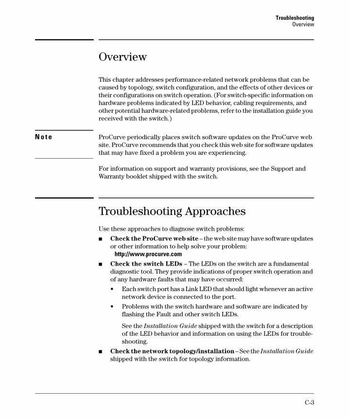
TroubleshootingOverview
Overview
This chapter addresses performance-related network problems that can be caused by topology, switch configuration, and the effects of other devices or their configurations on switch operation. (For switch-specific information on hardware problems indicated by LED behavior, cabling requirements, and other potential hardware-related problems, refer to the installation guide you received with the switch.)
N o t e ProCurve periodically places switch software updates on the ProCurve web site. ProCurve recommends that you check this web site for software updates that may have fixed a problem you are experiencing.
For information on support and warranty provisions, see the Support and Warranty booklet shipped with the switch.
Troubleshooting Approaches Use these approaches to diagnose switch problems:
■ Check the ProCurve web site – the web site may have software updates or other information to help solve your problem: http://www.procurve.com
■ Check the switch LEDs – The LEDs on the switch are a fundamental diagnostic tool. They provide indications of proper switch operation and of any hardware faults that may have occurred:
• Each switch port has a Link LED that should light whenever an active network device is connected to the port.
• Problems with the switch hardware and software are indicated by flashing the Fault and other switch LEDs.
See the Installation Guide shipped with the switch for a description of the LED behavior and information on using the LEDs for troubleshooting.
■ Check the network topology/installation – See the Installation Guide
shipped with the switch for topology information.
C-3
Troubleshooting Troubleshooting Approaches
■ Check the network cables – Cabling problems are a frequent cause of network faults. Check the cables for damage, correct type, and proper connections. You should also use a cable tester to check your cables for compliance to the relevant IEEE 802.3 specification. See the Installation
Guide shipped with the switch for correct cable types and connector pinouts.
■ Use the software tools:
• Web Browser Interface – Use the Port Utilization Graph and Alert Log in the web browser interface included in the switch to help isolate problems. See Chapter 5, “Using the Web Browser Interface” for operating information. These tools are available through the web browser interface: – Port Utilization Graph – Alert Log – Port Status and Port Counters screens – Diagnostic tools (Link test, Ping test, configuration file browser)
• Switch Console – For help in isolating problems, use the easy-to-access switch console built into the switch or Telnet to the switch console. See chapter 2, “Using the Menu Interface” and chapter 3, “Using the Command Line Interface (CLI)” for console operation information. These tools are available through the switch console: – Status and Counters screens – Event Log – Diagnostics tools (Link test, Ping test, configuration file browser,
and advanced user commands)
• ProCurve Manager / ProCurve Manager + – Use ProCurve Manager to help isolate problems and recommend solutions.
C-4
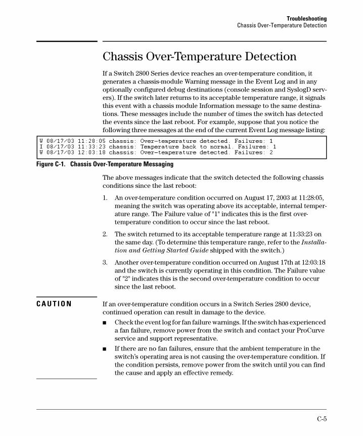
Troubleshooting Chassis Over-Temperature Detection
Chassis Over-Temperature Detection If a Switch 2800 Series device reaches an over-temperature condition, it generates a chassis-module Warning message in the Event Log and in any optionally configured debug destinations (console session and SyslogD servers). If the switch later returns to its acceptable temperature range, it signals this event with a chassis module Information message to the same destinations. These messages include the number of times the switch has detected the events since the last reboot. For example, suppose that you notice the following three messages at the end of the current Event Log message listing:
Figure C-1. Chassis Over-Temperature Messaging
The above messages indicate that the switch detected the following chassis conditions since the last reboot:
1. An over-temperature condition occurred on August 17, 2003 at 11:28:05, meaning the switch was operating above its acceptable, internal temperature range. The Failure value of "1" indicates this is the first over-temperature condition to occur since the last reboot.
2. The switch returned to its acceptable temperature range at 11:33:23 on the same day. (To determine this temperature range, refer to the Installa
tion and Getting Started Guide shipped with the switch.)
3. Another over-temperature condition occurred on August 17th at 12:03:18 and the switch is currently operating in this condition. The Failure value of "2" indicates this is the second over-temperature condition to occur since the last reboot.
C A U T I O N If an over-temperature condition occurs in a Switch Series 2800 device, continued operation can result in damage to the device.
■ Check the event log for fan failure warnings. If the switch has experienced a fan failure, remove power from the switch and contact your ProCurve service and support representative.
■ If there are no fan failures, ensure that the ambient temperature in the switch’s operating area is not causing the over-temperature condition. If the condition persists, remove power from the switch until you can find the cause and apply an effective remedy.
C-5
Troubleshooting Browser or Telnet Access Problems
Browser or Telnet Access Problems
Cannot access the web browser interface:
■ Access may be disabled by the Web Agent Enabled parameter in the switch console. Check the setting on this parameter by selecting:
2. Switch Configuration . . . 1. System Information
■ The switch may not have the correct IP address, subnet mask or gateway. Verify by connecting a console to the switch’s Console port and selecting:
2. Switch Configuration . . . 5. IP Configuration
Note: If DHCP/Bootp is used to configure the switch, the IP addressing can be verified by selecting:
1. Status and Counters . . .
2. Switch Management Address Information
also check the DHCP/Bootp server configuration to verify correct IP addressing.
■ If you are using DHCP to acquire the IP address for the switch, the IP address “lease time” may have expired so that the IP address has changed. For more information on how to “reserve” an IP address, refer to the documentation for the DHCP application that you are using.
■ If one or more IP-Authorized managers are configured, the switch allows web browser access only to a device having an authorized IP address. For more information on IP Authorized managers, see the Access Security
Guide for your switch.
■ Java™ applets may not be running on the web browser. They are required for the switch web browser interface to operate correctly. See the online Help on your web browser for how to run the Java applets.
C-6
Troubleshooting Browser or Telnet Access Problems
Cannot Telnet into the switch console from a station on the network:
■ Telnet access may be disabled by the Inbound Telnet Enabled parameter in the System Information screen of the menu interface:
2. Switch Configuration 1. System Information
■ The switch may not have the correct IP address, subnet mask, or gateway. Verify by connecting a console to the switch’s Console port and selecting:
2. Switch Configuration 5. IP Configuration
Note: If DHCP/Bootp is used to configure the switch, see the Note, above.
■ If you are using DHCP to acquire the IP address for the switch, the IP address “lease time” may have expired so that the IP address has changed. For more information on how to “reserve” an IP address, refer to the documentation for the DHCP application that you are using.
■ If one or more IP-Authorized managers are configured, the switch allows inbound telnet access only to a device having an authorized IP address. For more information on IP Authorized managers, see the Access Security
Guide for your switch.
C-7
Troubleshooting Unusual Network Activity
Unusual Network Activity
Network activity that fails to meet accepted norms may indicate a hardware problem with one or more of the network components, possibly including the switch. Such problems can also be caused by a network loop or simply too much traffic for the network as it is currently designed and implemented. Unusual network activity is usually indicated by the LEDs on the front of the switch or measured with the switch console interface or with a network management tool such as the ProCurve Manager. Refer to the Installation
Guide you received with the switch for information on using LEDs to identify unusual network activity.
A topology loop can also cause excessive network activity. The event log “FFI” messages can be indicative of this type of problem.
General Problems
The network runs slow; processes fail; users cannot access servers or
other devices. Broadcast storms may be occurring in the network. These may be due to redundant links between nodes.
• If you are configuring a port trunk, finish configuring the ports in the trunk before connecting the related cables. Otherwise you may inadvertently create a number of redundant links (i.e. topology loops) that will cause broadcast storms.
• Turn on Spanning Tree Protocol to block redundant links (i.e. topology loops)
• Check for FFI messages in the Event Log.
Duplicate IP Addresses. This is indicated by this Event Log message:
ip: Invalid ARP source: IP address on IP address
where: both instances of IP address are the same address, indicating the switch’s IP address has been duplicated somewhere on the network.
Duplicate IP Addresses in a DHCP Network. If you use a DHCP server to assign IP addresses in your network and you find a device with a valid IP address that does not appear to communicate properly with the server or other devices, a duplicate IP address may have been issued by the server. This can occur if a client has not released a DHCP-assigned IP address after the intended expiration time and the server “leases” the address to another device.
C-8
Troubleshooting Unusual Network Activity
This can also happen, for example, if the server is first configured to issue IP addresses with an unlimited duration, then is subsequently configured to issue IP addresses that will expire after a limited duration. One solution is to configure “reservations” in the DHCP server for specific IP addresses to be assigned to devices having specific MAC addresses. For more information, refer to the documentation for the DHCP server.
One indication of a duplicate IP address in a DHCP network is this Event Log message:
ip: Invalid ARP source: IP address on IP address
where: both instances of IP address are the same address, indicating the IP address that has been duplicated somewhere on the network.
The Switch Has Been Configured for DHCP/Bootp Operation, But Has
Not Received a DHCP or Bootp Reply. When the switch is first configured for DHCP/Bootp operation, or if it is rebooted with this configuration, it immediately begins sending request packets on the network. If the switch does not receive a reply to its DHCP/Bootp requests, it continues to periodically send request packets, but with decreasing frequency. Thus, if a DHCP or Bootp server is not available or accessible to the switch when DHCP/Bootp is first configured, the switch may not immediately receive the desired configuration. After verifying that the server has become accessible to the switch, reboot the switch to re-start the process.
Prioritization Problems
Ports configured for non-default prioritization (level 1 - 7) are not
performing the specified action. If the ports were placed in a trunk group after being configured for non-default prioritization, the priority setting was automatically reset to zero (the default). Ports in a trunk group operate only at the default priority setting.
IGMP-Related Problems
IP Multicast (IGMP) Traffic That Is Directed By IGMP Does Not Reach
IGMP Hosts or a Multicast Router Connected to a Port. IGMP must be enabled on the switch and the affected port must be configured for “Auto” or “Forward” operation.
IP Multicast Traffic Floods Out All Ports; IGMP Does Not Appear To
C-9
Troubleshooting Unusual Network Activity
C a u t i o n
Note
Filter Traffic. The IGMP feature does not operate if the switch or VLAN does not have an IP address configured manually or obtained through DHCP/Bootp. To verify whether an IP address is configured for the switch or VLAN, do either of the following:
■ Try Using the Web Browser Interface: If you can access the web browser interface, then an IP address is configured.
■ Try To Telnet to the Switch Console: If you can Telnet to the switch, then an IP address is configured.
■ Using the Switch Console Interface: From the Main Menu, check the Management Address Information screen by clicking on
1. Status and Counters 2. Switch Management Address Information
LACP-Related Problems
Unable to enable LACP on a port with the interface [e] < port-number > lacp command. In this case, the switch displays the following message:
Operation is not allowed for a trunked port.
You cannot enable LACP on a port while it is configured as a static Trunk port.To enable LACP on a static-trunked port:first use the no trunk [e] < port-number > command to disable the static trunk assignment, and then execute interface [e] < port-number > lacp.
Removing a port from a trunk without first disabling the port can create a traffic loop that can slow down or halt your network. Before removing a port from a trunk, ProCurve recommends that you either disable the port or disconnect it from the LAN.
Port-Based Access Control (802.1X)-Related Problems
To list the 802.1X port-access Event Log messages stored on the switch, use show log 802.
See also “Radius-Related Problems” on page C-13.
The switch does not receive a response to RADIUS authentication
requests. In this case, the switch will attempt authentication using the secondary method configured for the type of access you are using (console, Telnet, or SSH).
C-10
Troubleshooting Unusual Network Activity
There can be several reasons for not receiving a response to an authentication request. Do the following:
■ Use ping to ensure that the switch has access to the configured RADIUS servers.
■ Verify that the switch is using the correct encryption key (RADIUS secret key) for each server.
■ Verify that the switch has the correct IP address for each RADIUS server.
■ Ensure that the radius-server timeout period is long enough for network conditions.
The switch does not authenticate a client even though the RADIUS
server is properly configured and providing a response to the
authentication request. If the RADIUS server configuration for authenticating the client includes a VLAN assignment, ensure that the VLAN exists as a static VLAN on the switch. See “How 802.1X Authentication Affects VLAN Operation” in the Access Security Guide for your switch.
During RADIUS-authenticated client sessions, access to a VLAN on the
port used for the client sessions is lost. If the affected VLAN is configured as untagged on the port, it may be temporarily blocked on that port during an 802.1X session. This is because the switch has temporarily assigned another VLAN as untagged on the port to support the client access, as specified in the response from the RADIUS server. See “How 802.1X Authentication Affects VLAN Operation” in the Access Security Guide for your switch.
The switch appears to be properly configured as a supplicant, but
cannot gain access to the intended authenticator port on the switch
to which it is connected. If aaa authentication port-access is configured for Local, ensure that you have entered the local login (operator-level) username and password of the authenticator switch into the identity and secret parameters of the supplicant configuration. If instead, you enter the enable (managerlevel) username and password, access will be denied.
The supplicant statistics listing shows multiple ports with the same
authenticator MAC address. The link to the authenticator may have been moved from one port to another without the supplicant statistics having been cleared from the first port. Refer to the “Note on Supplicant Statistics” in the Access Security Guide for your switch.
The show port-access authenticator < port-list > command shows one or more
ports remain open after they have been configured with control
C-11
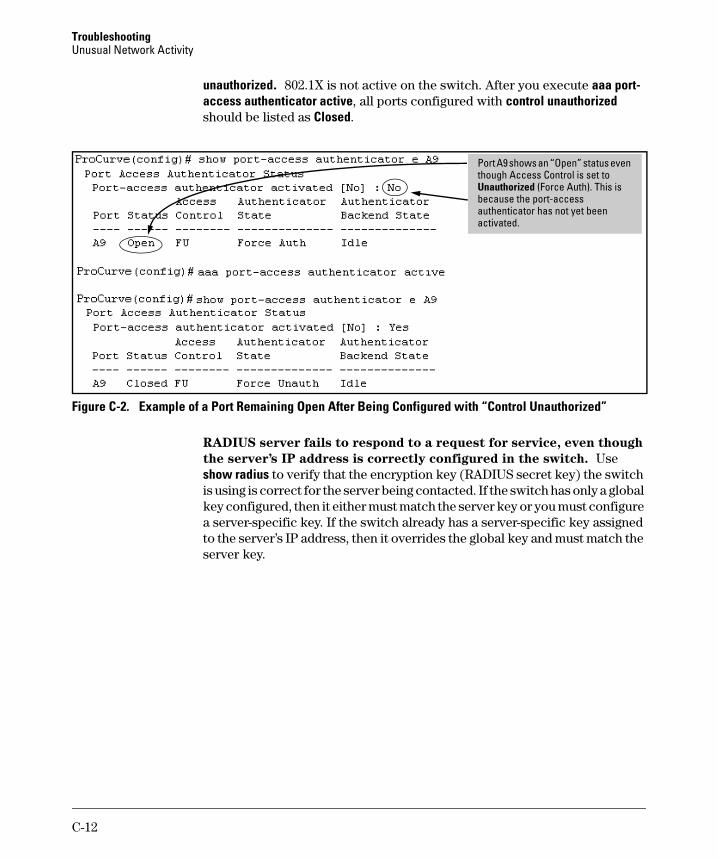
Troubleshooting Unusual Network Activity
unauthorized. 802.1X is not active on the switch. After you execute aaa port-access authenticator active, all ports configured with control unauthorized should be listed as Closed.
l is is
Port A9 shows an “Open” status even though Access Contro is set to Unauthorized (Force Auth). Thbecause the port-access authenticator has not yet been activated.
Figure C-2. Example of a Port Remaining Open After Being Configured with “Control Unauthorized”
RADIUS server fails to respond to a request for service, even though
the server’s IP address is correctly configured in the switch. Use show radius to verify that the encryption key (RADIUS secret key) the switch is using is correct for the server being contacted. If the switch has only a global key configured, then it either must match the server key or you must configure a server-specific key. If the switch already has a server-specific key assigned to the server’s IP address, then it overrides the global key and must match the server key.
C-12
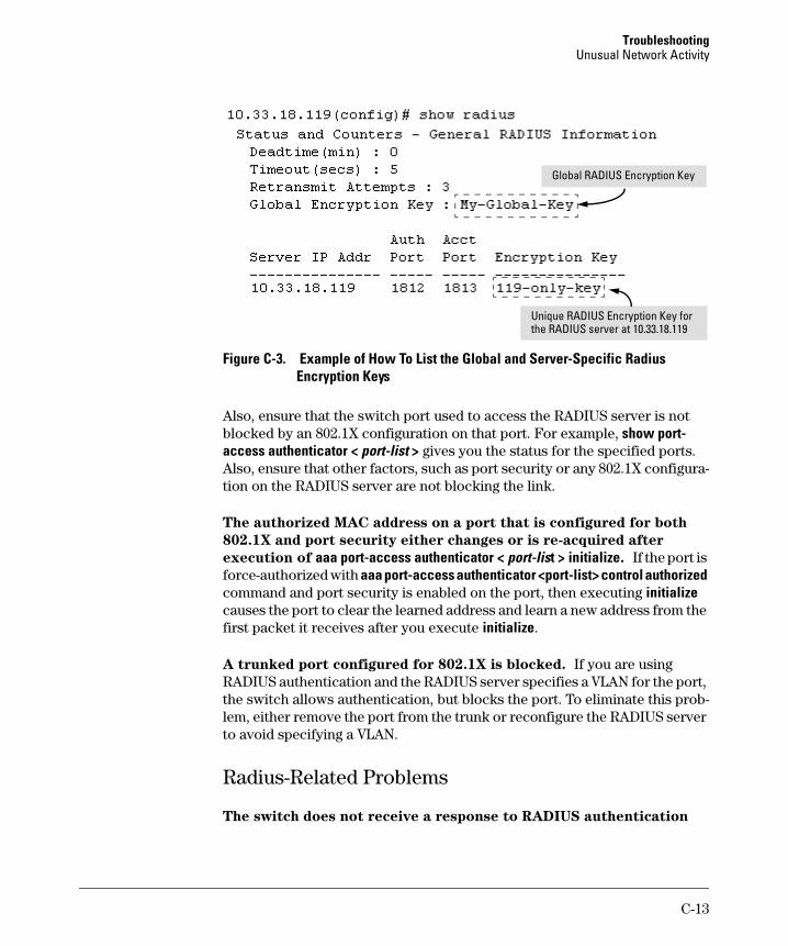
Troubleshooting Unusual Network Activity
Global RADIUS Encryption Key
Unique RADIUS Encryption Key for the RADIUS server at 10.33.18.119
Figure C-3. Example of How To List the Global and Server-Specific Radius Encryption Keys
Also, ensure that the switch port used to access the RADIUS server is not blocked by an 802.1X configuration on that port. For example, show port-access authenticator < port-list > gives you the status for the specified ports. Also, ensure that other factors, such as port security or any 802.1X configuration on the RADIUS server are not blocking the link.
The authorized MAC address on a port that is configured for both
802.1X and port security either changes or is re-acquired after
execution of aaa port-access authenticator < port-list > initialize. If the port is force-authorized with aaa port-access authenticator <port-list> control authorized command and port security is enabled on the port, then executing initialize causes the port to clear the learned address and learn a new address from the first packet it receives after you execute initialize.
A trunked port configured for 802.1X is blocked. If you are using RADIUS authentication and the RADIUS server specifies a VLAN for the port, the switch allows authentication, but blocks the port. To eliminate this problem, either remove the port from the trunk or reconfigure the RADIUS server to avoid specifying a VLAN.
Radius-Related Problems
The switch does not receive a response to RADIUS authentication
C-13
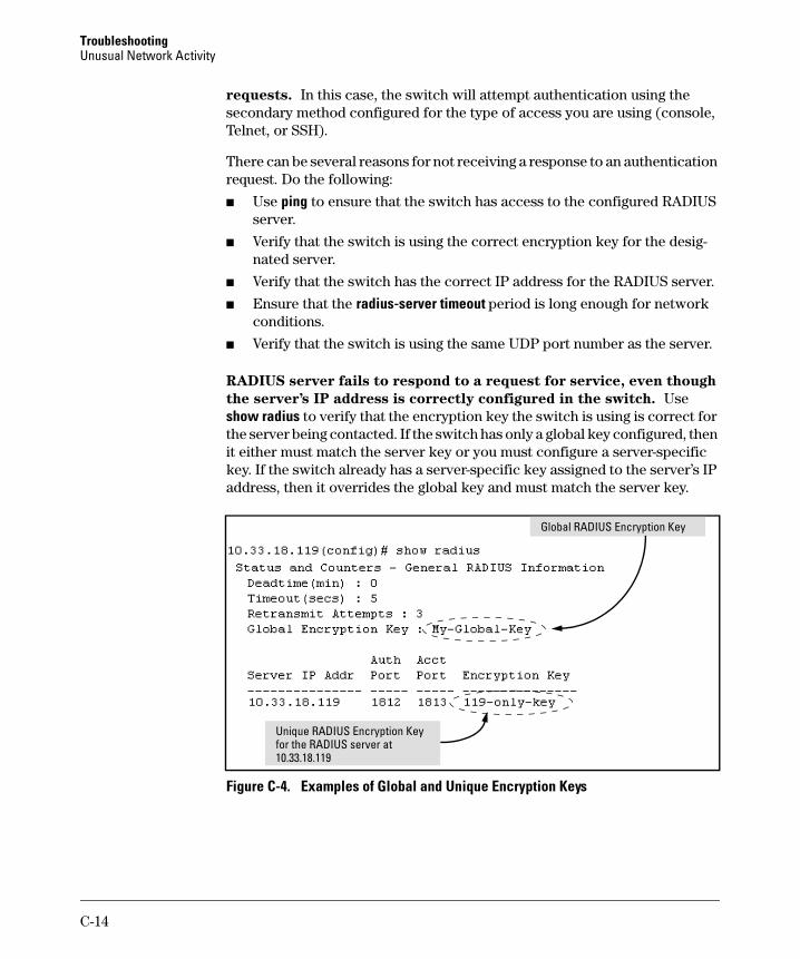
Troubleshooting Unusual Network Activity
requests. In this case, the switch will attempt authentication using the secondary method configured for the type of access you are using (console, Telnet, or SSH).
There can be several reasons for not receiving a response to an authentication request. Do the following:
■ Use ping to ensure that the switch has access to the configured RADIUS server.
■ Verify that the switch is using the correct encryption key for the designated server.
■ Verify that the switch has the correct IP address for the RADIUS server.
■ Ensure that the radius-server timeout period is long enough for network conditions.
■ Verify that the switch is using the same UDP port number as the server.
RADIUS server fails to respond to a request for service, even though
the server’s IP address is correctly configured in the switch. Use show radius to verify that the encryption key the switch is using is correct for the server being contacted. If the switch has only a global key configured, then it either must match the server key or you must configure a server-specific key. If the switch already has a server-specific key assigned to the server’s IP address, then it overrides the global key and must match the server key.
Global RADIUS Encryption Key
i
10.33.18.119
Un que RADIUS Encryption Key for the RADIUS server at
Figure C-4. Examples of Global and Unique Encryption Keys
C-14
Troubleshooting Unusual Network Activity
Spanning-Tree Protocol (STP) and Fast-Uplink Problems
C a u t i o n If you enable STP, it is recommended that you leave the remainder of the STP parameter settings at their default values until you have had an opportunity to evaluate STP performance in your network. Because incorrect STP settings can adversely affect network performance, you should avoid making changes without having a strong understanding of how STP operates. To learn the details of STP operation, refer to the IEEE 802.1D standard.
Broadcast Storms Appearing in the Network. This can occur when there are physical loops (redundant links) in the topology.Where this exists, you should enable STP on all bridging devices in the topology in order for the loop to be detected.
STP Blocks a Link in a VLAN Even Though There Are No Redundant
Links in that VLAN. In 802.1Q-compliant devices such as the switches covered by this guide, STP blocks redundant physical links even if they are in separate VLANs. A solution is to use only one, multiple-VLAN (tagged) link between the devices. Also, if ports are available, you can improve the bandwidth in this situation by using a port trunk. See the chapter on VLANs in the Advanced Traffic Management Guide..
Fast-Uplink Troubleshooting. Some of the problems that can result from incorrect usage of Fast-Uplink STP include temporary loops and generation of duplicate packets.
Problem sources can include:
■ Fast-Uplink is configured on a switch that is the STP root device.
■ Either the Hello Time or the Max Age setting (or both) is too long on one or more switches. Return the Hello Time and Max Age settings to their default values (2 seconds and 20 seconds, respectively, on a switch).
■ A “downlink” port is connected to a switch that is further away (in hop count) from the root device than the switch port on which fast-uplink STP is configured.
■ Two edge switches are directly linked to each other with a fast-uplink (Mode = Uplink) connection.
■ Fast uplink is configured on both ends of a link.
■ A switch serving as a backup STP root switch has ports configured for fast-uplink STP and has become the root device due to a failure in the original root device.
C-15
Troubleshooting Unusual Network Activity
SSH-Related Problems
Switch access refused to a client. Even though you have placed the cli-ent’s public key in a text file and copied the file (using the copy tftp pub-key-file command) into the switch, the switch refuses to allow the client to have access. If the source SSH client is an SSHv2 application, the public key may be in the PEM format, which the switch (SSHv1) does not interpret. Check the SSH client application for a utility that can convert the PEM-formatted key into an ASCII-formatted key.
Executing ip ssh does not enable SSH on the switch. The switch does not have a host key. Verify by executing show ip host-public-key. If you see the message
ssh cannot be enabled until a host key is configured(use 'crypto' command).
then you need to generate an SSH key pair for the switch. To do so, execute crypto key generate. (Refer to “2. Generating the Switch’s Public and Private Key Pair” in the Access Security Guide for your switch.)
C-16
Troubleshooting Unusual Network Activity
Switch does not detect a client’s public key that does appear in the
switch’s public key file (show ip client-public-key). The client’s public key entry in the public key file may be preceded by another entry that does not terminate with a new line (CR). In this case, the switch interprets the next sequential key entry as simply a comment attached to the preceding key entry. Where a public key file has more than one entry, ensure that all entries terminate with a new line (CR). While this is optional for the last entry in the file, not adding a new line to the last entry creates an error potential if you either add another key to the file at a later time or change the order of the keys in the file.
An attempt to copy a client public-key file into the switch has failed
and the switch lists one of the following messages.
Download failed: overlength key in key file.
Download failed: too many keys in key file.
Download failed: one or more keys is not a valid RSA public key.
The public key file you are trying to download has one of the following problems:
■ A key in the file is too long. The maximum key length is 1024 characters, including spaces. This could also mean that two or more keys are merged together instead of being separated by a <CR><LF>.
■ There are more than ten public keys in the key file.
■ One or more keys in the file is corrupted or is not a valid rsa public key.
Client ceases to respond (“hangs”) during connection phase. The switch does not support data compression in an SSH session. Clients will often have compression turned on by default, but will disable it during the negotiation phase. A client which does not recognize the compression-request FAILURE response may fail when attempting to connect. Ensure that compression is turned off before attempting a connection to prevent this problem.
Stacking-Related Problems
The Stack Commander Cannot Locate any Candidates. Stacking operates on the primary VLAN, which in the default configuration is the DEFAULT_VLAN. However, if another VLAN has been configured as the primary VLAN, and the Commander is not on the primary VLAN, then the Commander will not detect Candidates on the primary VLAN.
C-17
Troubleshooting Unusual Network Activity
TACACS-Related Problems
Event Log. When troubleshooting TACACS+ operation, check the switch’s Event Log for indications of problem areas.
All Users Are Locked Out of Access to the Switch. If the switch is functioning properly, but no username/password pairs result in console or Telnet access to the switch, the problem may be due to how the TACACS+ server and/or the switch are configured. Use one of the following methods to recover:
■ Access the TACACS+ server application and adjust or remove the configuration parameters controlling access to the switch.
■ If the above method does not work, try eliminating configuration changes in the switch that have not been saved to flash (boot-up configuration) by causing the switch to reboot from the boot-up configuration (which includes only the configuration changes made prior to the last write memory command.) If you did not use write memory to save the authentication configuration to flash, then pressing the Reset button or cycling the power reboots the switch with the boot-up configuration.
■ Disconnect the switch from network access to any TACACS+ servers and then log in to the switch using either Telnet or direct console port access. Because the switch cannot access a TACACS+ server, it will default to local authentication. You can then use the switch’s local Operator or Manager username/password pair to log on.
■ As a last resort, use the Clear/Reset button combination to reset the switch to its factory default boot-up configuration. Taking this step means you will have to reconfigure the switch to return it to operation in your network.
No Communication Between the Switch and the TACACS+ Server
Application. If the switch can access the server device (that is, it can ping the server), then a configuration error may be the problem. Some possibilities include:
■ The server IP address configured with the switch’s tacacs-server host command may not be correct. (Use the switch’s show tacacs-server command to list the TACACS+ server IP address.)
C-18
Troubleshooting Unusual Network Activity
■ The encryption key configured in the server does not match the encryption key configured in the switch (by using the tacacs-server key command). Verify the key in the server and compare it to the key configured in the switch. (Use show tacacs-server to list the global key. Use show config or show config running to list any server-specific keys.)
■ The accessible TACACS+ servers are not configured to provide service to the switch.
Access Is Denied Even Though the Username/Password Pair Is
Correct. Some reasons for denial include the following parameters controlled by your TACACS+ server application:
■ The account has expired.
■ The access attempt is through a port that is not allowed for the account.
■ The time quota for the account has been exhausted.
■ The time credit for the account has expired.
■ The access attempt is outside of the time frame allowed for the account.
■ The allowed number of concurrent logins for the account has been exceeded
For more help, refer to the documentation provided with your TACACS+ server application.
Unknown Users Allowed to Login to the Switch. Your TACACS+ application may be configured to allow access to unknown users by assigning them the privileges included in a default user profile. Refer to the documentation provided with your TACACS+ server application.
System Allows Fewer Login Attempts than Specified in the Switch
Configuration. Your TACACS+ server application may be configured to allow fewer login attempts than you have configured in the switch with the aaa authentication num-attempts command.
C-19
Troubleshooting Unusual Network Activity
TimeP, SNTP, or Gateway Problems
The Switch Cannot Find the Time Server or the Configured Gateway .
TimeP, SNTP, and Gateway access are through the primary VLAN, which in the default configuration is the DEFAULT_VLAN. If the primary VLAN has been moved to another VLAN, it may be disabled or does not have ports assigned to it.
VLAN-Related Problems
Monitor Port. When using the monitor port in a multiple VLAN environment, the switch handles broadcast, multicast, and unicast traffic output from the monitor port as follows:
■ If the monitor port is configured for tagged VLAN operation on the same VLAN as the traffic from monitored ports, the traffic output from the monitor port carries the same VLAN tag.
■ If the monitor port is configured for untagged VLAN operation on the same VLAN as the traffic from the monitored ports, the traffic output from the monitor port is untagged.
■ If the monitor port is not a member of the same VLAN as the traffic from the monitored ports, traffic from the monitored ports does not go out the monitor port.
None of the devices assigned to one or more VLANs on an 802.1Q-
compliant switch are being recognized. If multiple VLANs are being used on ports connecting 802.1Q-compliant devices, inconsistent VLAN IDs may have been assigned to one or more VLANs. For a given VLAN, the same VLAN ID must be used on all connected 802.1Q-compliant devices.
Link Configured for Multiple VLANs Does Not Support Traffic for One
or More VLANs. One or more VLANs may not be properly configured as “Tagged” or “Untagged”. A VLAN assigned to a port connecting two 802.1Q-compliant devices must be configured the same on both ports. For example, VLAN_1 and VLAN_2 use the same link between switch “X” and switch “Y”.
C-20
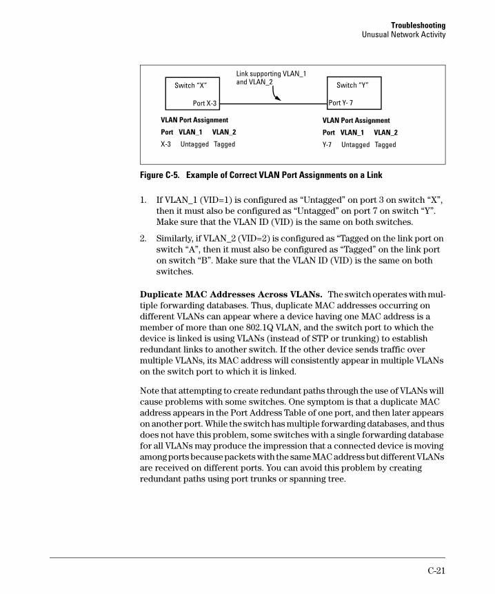
Troubleshooting Unusual Network Activity
X-3
Port X-3
Switch “Y” Switch “X”
Link supporting VLAN_1 and VLAN_2
VLAN Port Assignment
Port VLAN_1 VLAN_2
Untagged Tagged
Port Y- 7
VLAN Port Assignment
Port VLAN_1 VLAN_2
Y-7 Untagged Tagged
Figure C-5. Example of Correct VLAN Port Assignments on a Link
1. If VLAN_1 (VID=1) is configured as “Untagged” on port 3 on switch “X”, then it must also be configured as “Untagged” on port 7 on switch “Y”. Make sure that the VLAN ID (VID) is the same on both switches.
2. Similarly, if VLAN_2 (VID=2) is configured as “Tagged on the link port on switch “A”, then it must also be configured as “Tagged” on the link port on switch “B”. Make sure that the VLAN ID (VID) is the same on both switches.
Duplicate MAC Addresses Across VLANs. The switch operates with multiple forwarding databases. Thus, duplicate MAC addresses occurring on different VLANs can appear where a device having one MAC address is a member of more than one 802.1Q VLAN, and the switch port to which the device is linked is using VLANs (instead of STP or trunking) to establish redundant links to another switch. If the other device sends traffic over multiple VLANs, its MAC address will consistently appear in multiple VLANs on the switch port to which it is linked.
Note that attempting to create redundant paths through the use of VLANs will cause problems with some switches. One symptom is that a duplicate MAC address appears in the Port Address Table of one port, and then later appears on another port. While the switch has multiple forwarding databases, and thus does not have this problem, some switches with a single forwarding database for all VLANs may produce the impression that a connected device is moving among ports because packets with the same MAC address but different VLANs are received on different ports. You can avoid this problem by creating redundant paths using port trunks or spanning tree.
C-21
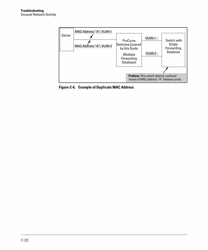
Troubleshooting Unusual Network Activity
Switches Covered
(Multiple
Database)
Single
Database
Problem:
Server ProCurve
by this Guide
Forwarding
Switch with
Forwarding
MAC Address “A”; VLAN 1
MAC Address “A”; VLAN 2
This switch detects continual moves of MAC address “A” between ports.
VLAN 1
VLAN 2
Figure C-6. Example of Duplicate MAC Address
C-22
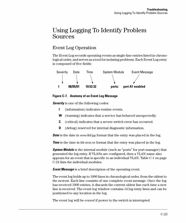
Troubleshooting Using Logging To Identify Problem Sources
I
I
Using Logging To Identify Problem Sources
Event Log Operation
The Event Log records operating events as single-line entries listed in chronological order, and serves as a tool for isolating problems. Each Event Log entry is composed of five fields:
Severity Date Time System Module Event Message
08/05/01 10:52:32 ports: port A1 enabled
Figure C-7. Anatomy of an Event Log Message
Severity is one of the following codes:
(information) indicates routine events.
W (warning) indicates that a service has behaved unexpectedly.
C (critical) indicates that a severe switch error has occurred.
D (debug) reserved for internal diagnostic information.
Date is the date in mm/dd/yy format that the entry was placed in the log.
Time is the time in hh:mm:ss format that the entry was placed in the log.
System Module is the internal module (such as “ports” for port manager) that generated the log entry. If VLANs are configured, then a VLAN name also appears for an event that is specific to an individual VLAN. Table C-1 on pageC-24 lists the individual modules.
Event Message is a brief description of the operating event.
The event log holds up to 1000 lines in chronological order, from the oldest to the newest. Each line consists of one complete event message. Once the loghas received 1000 entries, it discards the current oldest line each time a newline is received. The event log window contains 14 log entry lines and can bepositioned to any location in the log.
The event log will be erased if power to the switch is interrupted.
C-23
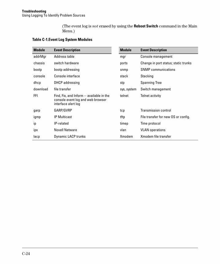
Troubleshooting Using Logging To Identify Problem Sources
(The event log is not erased by using the Reboot Switch command in the Main Menu.)
Table C-1.Event Log System Modules
Event Description Event DescriptionModule Module
addrMgr Address table mgr Console management
chassis switch hardware ports Change in port status; static trunks
bootp bootp addressing snmp SNMP communications
console Console interface stack Stacking
dhcp DHCP addressing stp Spanning Tree
download file transfer sys, system Switch management
FFI Find, Fix, and Inform -- available in the telnet Telnet activity console event log and web browser interface alert log
garp GARP/GVRP tcp Transmission control
igmp IP Multicast tftp File transfer for new OS or config.
ip IP-related timep Time protocol
ipx Novell Netware vlan VLAN operations
lacp Dynamic LACP trunks Xmodem Xmodem file transfer
C-24
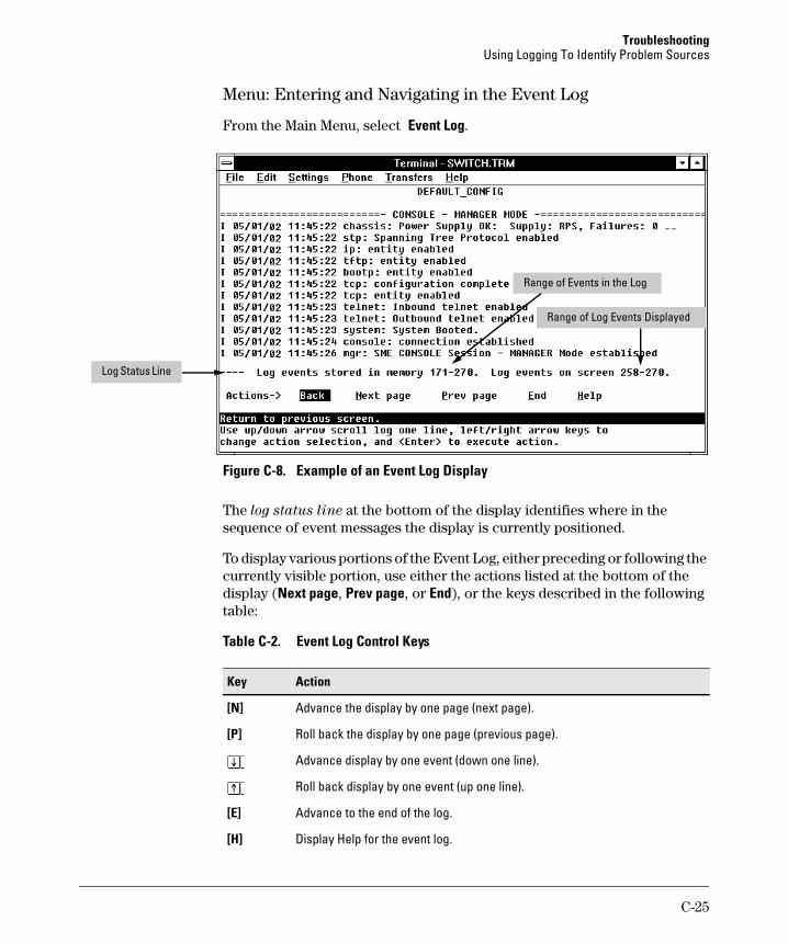
Troubleshooting Using Logging To Identify Problem Sources
Menu: Entering and Navigating in the Event Log
From the Main Menu, select Event Log.
Range of Events in the Log
Range of Log Events Displayed
Log Status Line
Figure C-8. Example of an Event Log Display
The log status line at the bottom of the display identifies where in the sequence of event messages the display is currently positioned.
To display various portions of the Event Log, either preceding or following the currently visible portion, use either the actions listed at the bottom of the display (Next page, Prev page, or End), or the keys described in the following table:
Table C-2. Event Log Control Keys
Key Action
[N] Advance the display by one page (next page).
[P] Roll back the display by one page (previous page).
[v] Advance display by one event (down one line).
[^] Roll back display by one event (up one line).
[E] Advance to the end of the log.
[H] Display Help for the event log.
C-25
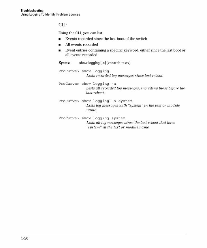
Troubleshooting Using Logging To Identify Problem Sources
CLI:
Using the CLI, you can list
■ Events recorded since the last boot of the switch
■ All events recorded
■ Event entries containing a specific keyword, either since the last boot or all events recorded
Syntax: show logging [-a] [<search-text>]
ProCurve> show loggingLists recorded log messages since last reboot.
ProCurve> show logging -aLists all recorded log messages, including those before the
last reboot.
ProCurve> show logging -a systemLists log messages with “system” in the text or module
name.
ProCurve> show logging systemLists all log messages since the last reboot that have
“system” in the text or module name.
C-26
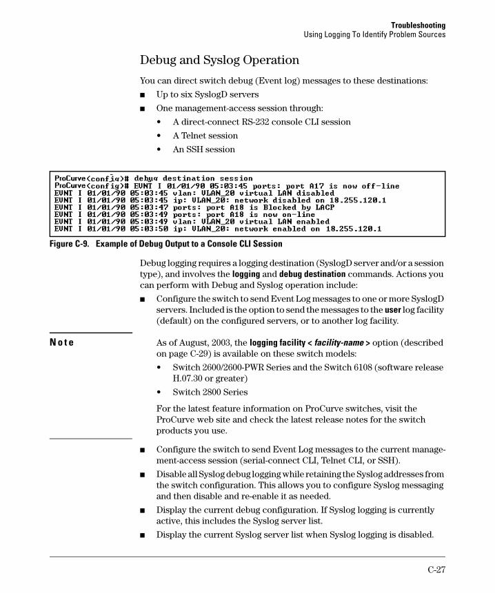
Troubleshooting Using Logging To Identify Problem Sources
Debug and Syslog Operation
You can direct switch debug (Event log) messages to these destinations:
■ Up to six SyslogD servers
■ One management-access session through:
• A direct-connect RS-232 console CLI session
• A Telnet session
• An SSH session
Figure C-9. Example of Debug Output to a Console CLI Session
Debug logging requires a logging destination (SyslogD server and/or a session type), and involves the logging and debug destination commands. Actions you can perform with Debug and Syslog operation include:
■ Configure the switch to send Event Log messages to one or more SyslogD servers. Included is the option to send the messages to the user log facility (default) on the configured servers, or to another log facility.
N o t e As of August, 2003, the logging facility < facility-name > option (described on page C-29) is available on these switch models:
• Switch 2600/2600-PWR Series and the Switch 6108 (software release H.07.30 or greater)
• Switch 2800 Series
For the latest feature information on ProCurve switches, visit the ProCurve web site and check the latest release notes for the switch products you use.
■ Configure the switch to send Event Log messages to the current manage-ment-access session (serial-connect CLI, Telnet CLI, or SSH).
■ Disable all Syslog debug logging while retaining the Syslog addresses from the switch configuration. This allows you to configure Syslog messaging and then disable and re-enable it as needed.
■ Display the current debug configuration. If Syslog logging is currently active, this includes the Syslog server list.
■ Display the current Syslog server list when Syslog logging is disabled.
C-27
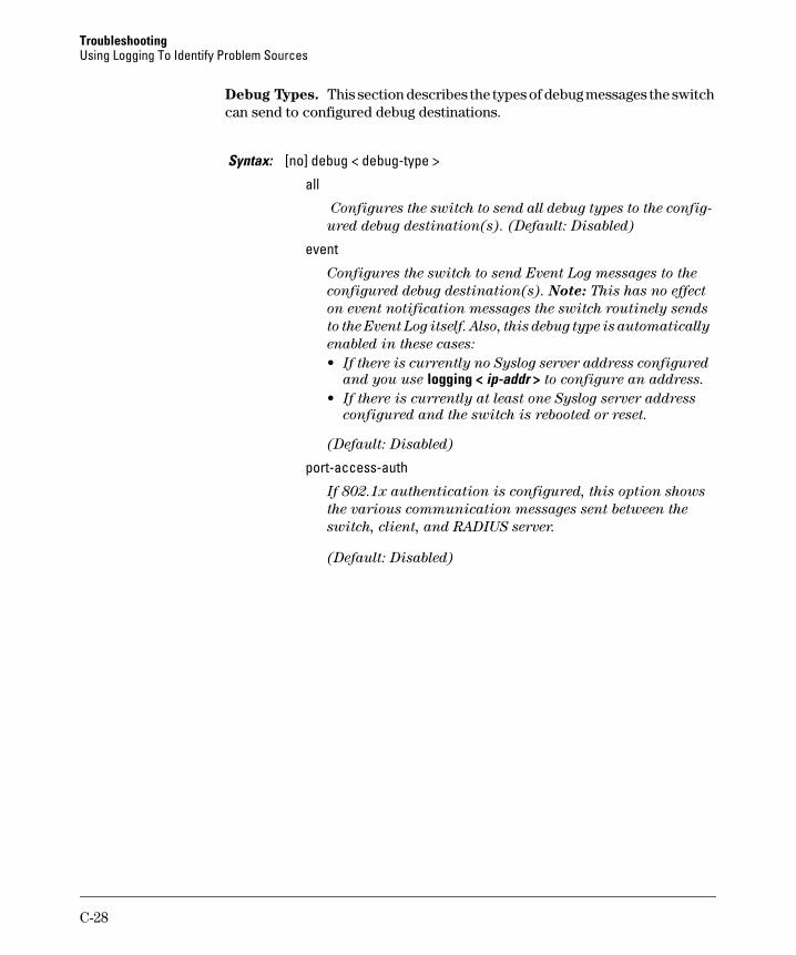
Troubleshooting Using Logging To Identify Problem Sources
Debug Types. This section describes the types of debug messages the switch can send to configured debug destinations.
Syntax: [no] debug < debug-type >
all
Configures the switch to send all debug types to the config
ured debug destination(s). (Default: Disabled)
event
Configures the switch to send Event Log messages to the
configured debug destination(s). Note: This has no effect
on event notification messages the switch routinely sends
to the Event Log itself. Also, this debug type is automatically
enabled in these cases:
• If there is currently no Syslog server address configured
and you use logging < ip-addr > to configure an address.
• If there is currently at least one Syslog server address
configured and the switch is rebooted or reset.
(Default: Disabled)
port-access-auth
If 802.1x authentication is configured, this option shows
the various communication messages sent between the
switch, client, and RADIUS server.
(Default: Disabled)
C-28
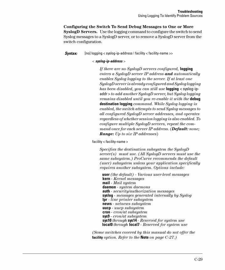
Troubleshooting Using Logging To Identify Problem Sources
Configuring the Switch To Send Debug Messages to One or More
SyslogD Servers. Use the logging command to configure the switch to send Syslog messages to a SyslogD server, or to remove a SyslogD server from the switch configuration.
Syntax: [no] logging < syslog-ip-address | facility < facility-name >>
< syslog-ip-address >
If there are no SyslogD servers configured, logging enters a SyslogD server IP address and automatically
enables Syslog logging to the server. If at least one
SyslogD server is already configured and Syslog logging
has been disabled, you can still use logging < syslog-ip-addr > to add another SyslogD server, but Syslog logging
remains disabled until you re-enable it with the debug destination logging command. While Syslog logging is
enabled, the switch attempts to send Syslog messages to
all configured SyslogD server addresses, and operates
regardless of whether session logging is also enabled. To
configure multiple SyslogD servers, repeat the com
mand once for each server IP address. (Default: none;
Range: Up to six IP addresses)
facility < facility-name >
Specifies the destination subsystem the SyslogD
server(s) must use. (All SyslogD servers must use the
same subsystem.) ProCurve recommends the default
(user) subsystem unless your application specifically
requires another subsystem. Options include:
user (the default) - Various user-level messages kern - Kernel messages mail - Mail system daemon - system daemons auth - security/authorization messages syslog - messages generated internally by Syslog lpr - line printer subsystem news - netnews subsystem uucp - uucp subsystem cron - cron/at subsystem sys9 - cron/at subsystem sys10 through sys14 - Reserved for system use local0 through local7 - Reserved for system use
(Some switches covered by this manual do not offer the
facility option. Refer to the Note on page C-27.)
C-29
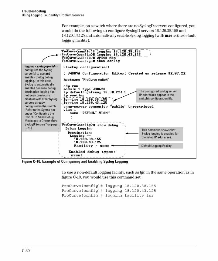
Troubleshooting Using Logging To Identify Problem Sources
For example, on a switch where there are no SyslogD servers configured, you would do the following to configure SyslogD servers 18.120.38.155 and 18.120.43.125 and automatically enable Syslog logging (with user as the default logging facility):
logging < >
and
l
di
i
i
i
syslog-ip-addrconfigures the Syslog server(s) to use enables Syslog debug ogging. (In this case, Syslog is automatically enabled because debug destination logging has not been previously
sabled with other Syslog servers already configured n the switch. (Refer to the Syntax box under “Configuring the Switch To Send Debug Messages to One or More SyslogD Servers” on page C-29.)
The configured Syslog server IP addresses appear n the switch’s configuration file.
This command shows that Syslog logg ng is enabled for the listed IP addresses.
Default Logging Facility
Figure C-10. Example of Configuring and Enabling Syslog Logging
To use a non-default logging facility, such as lpr, in the same operation as in figure C-10, you would use this command set:
ProCurve(config)# logging 18.120.38.155ProCurve(config)# logging 18.120.43.125ProCurve(config)# logging facility lpr
C-30
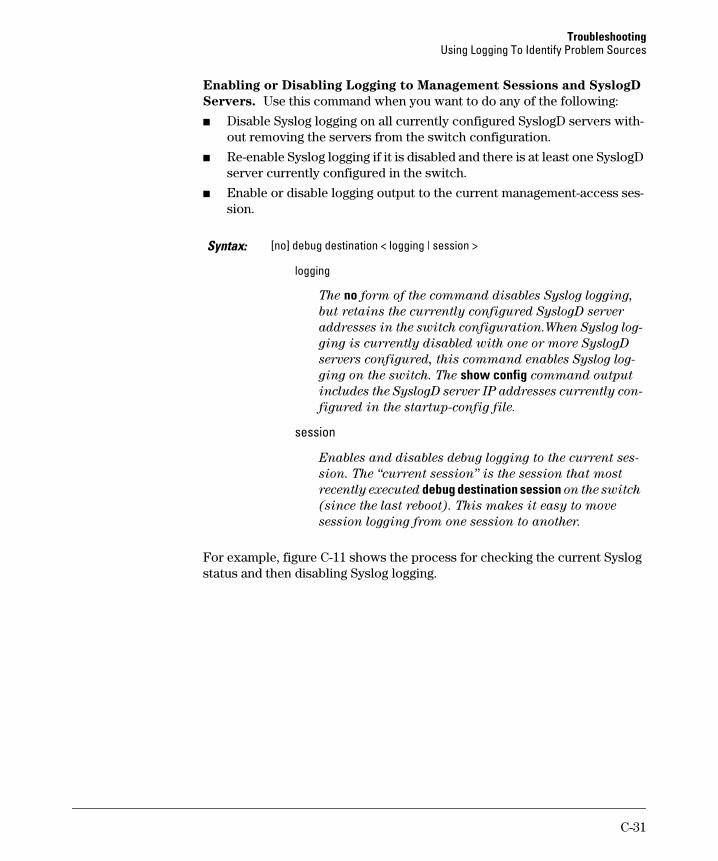
Troubleshooting Using Logging To Identify Problem Sources
Enabling or Disabling Logging to Management Sessions and SyslogD
Servers. Use this command when you want to do any of the following:
■ Disable Syslog logging on all currently configured SyslogD servers without removing the servers from the switch configuration.
■ Re-enable Syslog logging if it is disabled and there is at least one SyslogD server currently configured in the switch.
■ Enable or disable logging output to the current management-access session.
Syntax: [no] debug destination < logging | session >
logging
The no form of the command disables Syslog logging,
but retains the currently configured SyslogD server
addresses in the switch configuration.When Syslog log
ging is currently disabled with one or more SyslogD
servers configured, this command enables Syslog log
ging on the switch. The show config command output
includes the SyslogD server IP addresses currently con
figured in the startup-config file.
session
Enables and disables debug logging to the current ses
sion. The “current session” is the session that most
recently executed debug destination session on the switch
(since the last reboot). This makes it easy to move
session logging from one session to another.
For example, figure C-11 shows the process for checking the current Syslog status and then disabling Syslog logging.
C-31
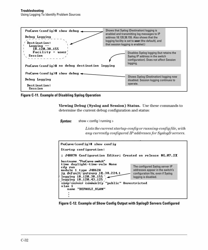
Troubleshooting Using Logging To Identify Problem Sources
lso shows that the l i
)
Shows that Syslog (Destination) logging is enabled and transmitting log messages to IP address 18.120.38.155. Aogging facil ty is set to user (the default), and that session logging is enabled.
Disabl i
i
es Syslog logg ng (but retains the Syslog IP address in the switch configuration). Does not affect Session logging.
Shows Syslog (Destination) logg ng now disabled. Session logging continues to operate.
Figure C-11. Example of Disabling Syslog Operation
Viewing Debug (Syslog and Session) Status. Use these commands to determine the current debug configuration and status:
Syntax: show < config | running >
Lists the current startup-config or running-config file, with
any currently configured IP addresses for SyslogD servers.
The configured Syslog server IP addresses appear in the switch’s configuration file, even if Syslog logging is disabled.
Figure C-12. Example of Show Config Output with SyslogD Servers Configured
C-32
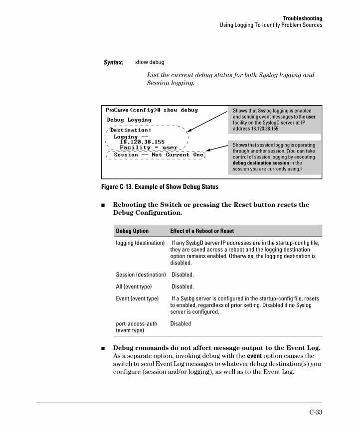
Troubleshooting Using Logging To Identify Problem Sources
Syntax: show debug
List the current debug status for both Syslog logging and
Session logging.
address 18.120.38.155.
l l in the
Shows that Syslog logging is enabled and sending event messages to the user facility on the SyslogD server at IP
Shows that session logging is operating through another session. (You can take contro of session ogging by executing debug destination sessionsession you are currently using.)
Figure C-13. Example of Show Debug Status
■ Rebooting the Switch or pressing the Reset button resets the
Debug Configuration.
Effect of a Reboot or ResetDebug Option
logging (destination) If any SyslogD server IP addresses are in the startup-config file, they are saved across a reboot and the logging destination option remains enabled. Otherwise, the logging destination is disabled.
Session (destination) Disabled.
All (event type) Disabled.
Event (event type) If a Syslog server is configured in the startup-config file, resets to enabled, regardless of prior setting. Disabled if no Syslog server is configured.
port-access-auth Disabled (event type)
■ Debug commands do not affect message output to the Event Log.
As a separate option, invoking debug with the event option causes the switch to send Event Log messages to whatever debug destination(s) you configure (session and/or logging), as well as to the Event Log.
C-33
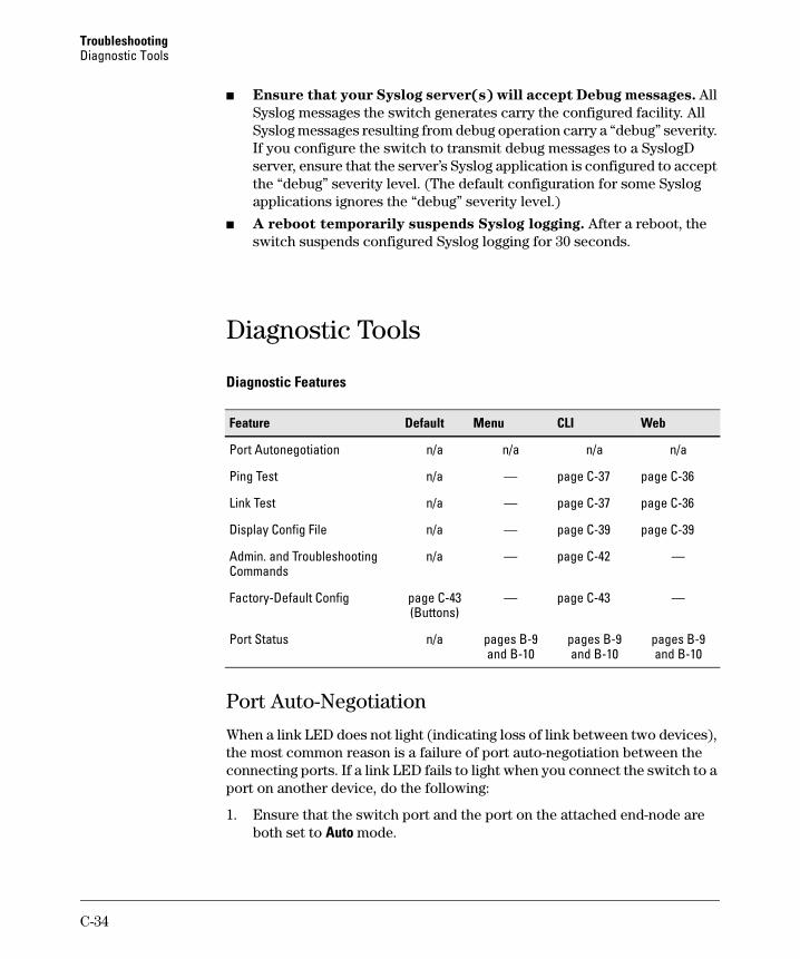
Troubleshooting Diagnostic Tools
■ Ensure that your Syslog server(s) will accept Debug messages. All Syslog messages the switch generates carry the configured facility. All Syslog messages resulting from debug operation carry a “debug” severity. If you configure the switch to transmit debug messages to a SyslogD server, ensure that the server’s Syslog application is configured to accept the “debug” severity level. (The default configuration for some Syslog applications ignores the “debug” severity level.)
■ A reboot temporarily suspends Syslog logging. After a reboot, the switch suspends configured Syslog logging for 30 seconds.
CLIFeature Default Menu Web
Diagnostic Tools
Diagnostic Features
Port Autonegotiation n/a n/a n/a n/a
Ping Test n/a — page C-37 page C-36
Link Test n/a — page C-37 page C-36
Display Config File n/a — page C-39 page C-39
Admin. and Troubleshooting n/a — page C-42 — Commands
Factory-Default Config page C-43 — page C-43 — (Buttons)
Port Status n/a pages B-9 pages B-9 pages B-9 and B-10 and B-10 and B-10
Port Auto-Negotiation
When a link LED does not light (indicating loss of link between two devices), the most common reason is a failure of port auto-negotiation between the connecting ports. If a link LED fails to light when you connect the switch to a port on another device, do the following:
1. Ensure that the switch port and the port on the attached end-node are both set to Auto mode.
C-34
Troubleshooting Diagnostic Tools
2. If the attached end-node does not have an Auto mode setting, then you must manually configure the switch port to the same setting as the end-node port. See Chapter 10, “Port Status and Basic Configuration”.
Ping and Link Tests
The Ping test and the Link test are point-to-point tests between your switch and another IEEE 802.3-compliant device on your network. These tests can tell you whether the switch is communicating properly with another device.
N o t e To respond to a Ping test or a Link test, the device you are trying to reach must be IEEE 802.3-compliant.
Ping Test. This is a test of the path between the switch and another device on the same or another IP network that can respond to IP packets (ICMP Echo Requests).
Link Test. This is a test of the connection between the switch and a designated network device on the same LAN (or VLAN, if configured). During the link test, IEEE 802.2 test packets are sent to the designated network device in the same VLAN or broadcast domain. The remote device must be able to respond with an 802.2 Test Response Packet.
C-35
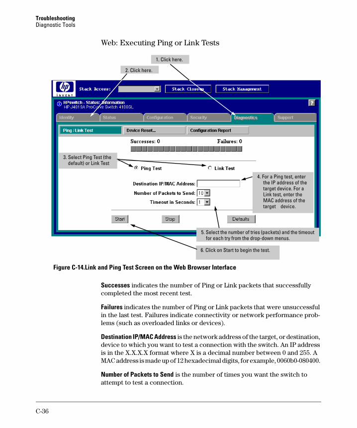
Troubleshooting Diagnostic Tools
Web: Executing Ping or Link Tests
2. Click here.
1. Click here.
the IP address of the4. For a Ping test, enter
target device. For a Link test, enter the
MAC address of the target device.
3. Select Ping Test (the default) or Link Test
5. Select the number of tries (packets) and the timeout for each try from the drop-down menus.
6. Click on Start to begin the test.
Figure C-14.Link and Ping Test Screen on the Web Browser Interface
Successes indicates the number of Ping or Link packets that successfully completed the most recent test.
Failures indicates the number of Ping or Link packets that were unsuccessful in the last test. Failures indicate connectivity or network performance problems (such as overloaded links or devices).
Destination IP/MAC Address is the network address of the target, or destination, device to which you want to test a connection with the switch. An IP address is in the X.X.X.X format where X is a decimal number between 0 and 255. A MAC address is made up of 12 hexadecimal digits, for example, 0060b0-080400.
Number of Packets to Send is the number of times you want the switch to attempt to test a connection.
C-36
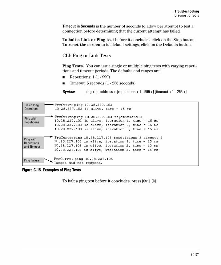
Troubleshooting Diagnostic Tools
Timeout in Seconds is the number of seconds to allow per attempt to test a connection before determining that the current attempt has failed.
To halt a Link or Ping test before it concludes, click on the Stop button. To reset the screen to its default settings, click on the Defaults button.
CLI: Ping or Link Tests
Ping Tests. You can issue single or multiple ping tests with varying repetitions and timeout periods. The defaults and ranges are:
■ Repetitions: 1 (1 - 999)
■ Timeout: 5 seconds (1 - 256 seconds)
Syntax: ping < ip-address > [repetitions < 1 - 999 >] [timeout < 1 - 256 >]
Basic Ping Operation
Ping with Repetitions
Ping with Repetitions and Timeout
Ping Failure
Figure C-15. Examples of Ping Tests
To halt a ping test before it concludes, press [Ctrl] [C].
C-37
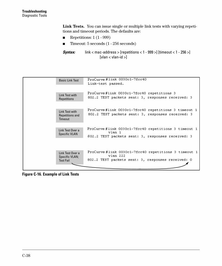
Troubleshooting Diagnostic Tools
Link Tests. You can issue single or multiple link tests with varying repetitions and timeout periods. The defaults are:
■ Repetitions: 1 (1 - 999)
■ Timeout: 5 seconds (1 - 256 seconds)
Syntax: link < mac-address > [repetitions < 1 - 999 >] [timeout < 1 - 256 >] [vlan < vlan-id >]
i
Ti
Basic Link Test
Link Test w th Repetitions
Link Test with Repetitions and
meout
Link Test Over a Specific VLAN
Link Test Over a Specific VLAN; Test Fail
Figure C-16. Example of Link Tests
C-38
Troubleshooting Diagnostic Tools
Displaying the Configuration File
The complete switch configuration is contained in a file that you can browse from either the web browser interface or the CLI. It may be useful in some troubleshooting scenarios to view the switch configuration.
CLI: Viewing the Configuration File
Using the CLI, you can display either the running configuration or the startup configuration. (For more on these topics, see appendix C, “Switch Memory and Configuration”.)
Syntax: write terminal Displays the running-config file.
show running-config Displays the running-config file.
show config Displays the startup-config file.
Web: Viewing the Configuration File
To display the running configuration, through the web browser interface:
1. Click on the Diagnostics tab.
2. Click on Configuration Report
3. Use the right-side scroll bar to scroll through the configuration listing.
C-39
Troubleshooting Diagnostic Tools
Listing Switch Configuration and Operation Details for Help in Troubleshooting
Release G.04.05 and greater includes the show tech command. This command outputs, in a single listing, switch operating and running configuration details from several internal switch sources, including:
■ Image stamp (software version data)
■ Running configuration
■ Event Log listing
■ Boot History
■ Port settings
■ Status and counters — port status
■ IP routes
■ Status and counters — VLAN information
■ GVRP support
■ Load balancing (trunk and LACP)
■ Stacking status — this switch
■ Stacking status — all
Syntax: show tech
Executing show tech outputs a data listing to your terminal emulator. However, using your terminal emulator’s text capture features, you can also save show tech data to a text file for viewing, printing, or sending to an associate. For example, if your terminal emulator is the Hyperterminal application available with Microsoft® Windows® software, you can copy the show tech output to a file and then use either Microsoft Word or Notepad to display the data. (In this case, Microsoft Word provides the data in an easier-to-read format.)
To Copy show tech output to a Text File. This example uses the Microsoft Windows terminal emulator. To use another terminal emulator application, refer to the documentation provided with that application.
C-40
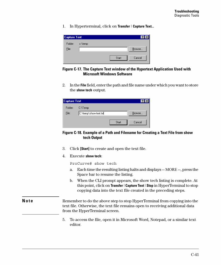
Troubleshooting Diagnostic Tools
1. In Hyperterminal, click on Transfer | Capture Text...
Figure C-17. The Capture Text window of the Hypertext Application Used with Microsoft Windows Software
2. In the File field, enter the path and file name under which you want to store the show tech output.
Figure C-18. Example of a Path and Filename for Creating a Text File from show tech Output
3. Click [Start] to create and open the text file.
4. Execute show tech:
ProCurve# show tech
a. Each time the resulting listing halts and displays -- MORE --, press the Space bar to resume the listing.
b. When the CLI prompt appears, the show tech listing is complete. At this point, click on Transfer | Capture Text | Stop in HyperTerminal to stop copying data into the text file created in the preceding steps.
N o t e Remember to do the above step to stop HyperTerminal from copying into the text file. Otherwise, the text file remains open to receiving additional data from the HyperTerminal screen.
5. To access the file, open it in Microsoft Word, Notepad, or a similar text editor.
C-41
Troubleshooting Diagnostic Tools
CLI Administrative and Troubleshooting Commands
These commands provide information or perform actions that you may find helpful in troubleshooting operating problems with the switch.
N o t e For more on the CLI, refer to “Using the Command Line Interface (CLI)” on page 4-1.
Syntax: show version Shows the software version currently running on the switch
and the flash image from which the switch booted (primary
or secondary).
show boot-history Displays the switch shutdown history.
show history Displays the current command history.
[no] page Toggles the paging mode for display commands between
continuous listing and per-page listing.
setup Displays the Switch Setup screen from the menu interface.
repeat Repeatedly executes the previous command until a key is
pressed.
kill Terminates all other active sessions.
C-42
Troubleshooting Restoring the Factory-Default Configuration
Restoring the Factory-Default Configuration
As part of your troubleshooting process, it may become necessary to return the switch configuration to the factory default settings. This process momentarily interrupts the switch operation, clears any passwords, clears the console event log, resets the network counters to zero, performs a complete self test, and reboots the switch into its factory default configuration including deleting an IP address. There are two methods for resetting to the factory-default configuration:
■ CLI
■ Clear/Reset button combination
N o t e ProCurve recommends that you save your configuration to a TFTP server before resetting the switch to its factory-default configuration. You can also save your configuration via Xmodem, to a directly connected PC.
Using the CLI
This command operates at any level except the Operator level.
Syntax: erase startup-configuration Deletes the startup-config file in flash so that the switch will
reboot with its factory-default configuration.
N o t e The erase startup-config command does not clear passwords.
Using the Clear/Reset Buttons
To execute the factory default reset, perform these steps:
1. Using pointed objects, simultaneously press both the Reset and Clear buttons on the front of the switch.
2. Continue to press the Clear button while releasing the Reset button.
3. When the Self Test LED begins to flash, release the Clear button.
The switch will then complete its self test and begin operating with the configuration restored to the factory default settings.
C-43
Troubleshooting Restoring a Flash Image
Restoring a Flash Image
The switch can lose its operating system if either the primary or secondary flash image location is empty or contains a corrupted OS file and an operator uses the erase flash command to erase a good OS image file from the opposite flash location.
To Recover from an Empty or Corrupted Flash State. Use the switch’s console serial port to connect to a workstation or laptop computer that has the following:
■ A terminal emulator program with Xmodem capability, such as the Hyper-Terminal program included in Windows PC software.
■ A copy of a good OS image file for the switch.
N o t e The following procedure requires the use of Xmodem, and copies an OS image into primary flash only.
This procedure assumes you are using HyperTerminal as your terminal emulator. If you use a different terminal emulator, you may need to adapt this procedure to the operation of your particular emulator.
1. Start the terminal emulator program.
2. Ensure that the terminal program is configured as follows:
■ Baud rate: 9600 ■ 1 stop bit
■ No parity ■ No flow control
■ 8 Bits
3. Use the Reset button to reset the switch. The following prompt should then appear in the terminal emulator:
Enter h or ? for help.
=>
C-44

Troubleshooting Restoring a Flash Image
4. Since the OS file is large, you can increase the speed of the download by changing the switch console and terminal emulator baud rates to a high speed. For example:
a. Change the switch baud rate to 115,200 Bps.
=> sp 115200
b. Change the terminal emulator baud rate to match the switch speed: i. In HyperTerminal, select Call | Disconnect. ii. Select File | Properties. iii. Click on Configure . . .. iv. Change the baud rate to 115200. v. Click on [OK]. In the next window, click on [OK] again. vi. Select Call | Connect vii. Press [Enter] one or more times to display the => prompt.
5. Start the Console Download utility by typing do at the => prompt and pressing [Enter]:
=> do
6. You will then see this prompt:
7. At the above prompt:
a. Type y (for Yes)
b. Select Transfer | File in HyperTerminal.
c. Enter the appropriate filename and path for the OS image.
d. Select the Xmodem protocol (and not the 1k Xmodem protocol).
e. Click on [Send].
If you are using HyperTerminal, you will see a screen similar to the following to indicate that the download is in progress:
C-45
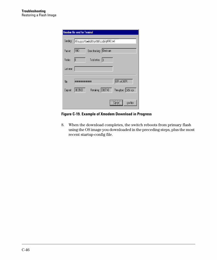
Troubleshooting Restoring a Flash Image
Figure C-19. Example of Xmodem Download in Progress
8. When the download completes, the switch reboots from primary flash using the OS image you downloaded in the preceding steps, plus the most recent startup-config file.
C-46
D
MAC Address Management
Contents
Overview . . . . . . . . . . . . . . . . . . . . . . . . . . . . . . . . . . . . . . . . . . . . . . . . . . . . . D-2
Determining MAC Addresses in the Switch . . . . . . . . . . . . . . . . . . . . . . . . D-2
Menu: Viewing the Switch’s MAC Addresses . . . . . . . . . . . . . . . . . . . . D-3
CLI: Viewing the Port and VLAN MAC Addresses . . . . . . . . . . . . . . . . D-4
Viewing the MAC Addresses of Connected Devices on Series 2600/2600-PWR, 2800 and 4100gl Switches . . . . . . . . . . . . . . . . . . . D-6
D-1
MAC Address Management Overview
Overview
The switch assigns MAC addresses in these areas:
■ For management functions:
• One Base MAC address assigned to the default VLAN (VID = 1)
• Additional MAC address(es) corresponding to additional VLANs you configure in the switch
■ For internal switch operations: One MAC address per port (See "CLI: Viewing the Port and VLAN MAC Addresses" on page D-4.)
MAC addresses are assigned at the factory. The switch automatically implements these addresses for VLANs and ports as they are added to the switch.
N o t e The switch’s base MAC address is also printed on a label affixed to the back of the switch.
Determining MAC Addresses in the Switch
MAC Address Viewing Methods
Feature Default Menu CLI Web
view switch’s base (default vlan) MAC address n/a D-3 D-4 — and the addressing for any added VLANs
view port MAC addresses (hexadecimal format) n/a — D-4 —
■ Use the menu interface to view the switch’s base MAC address and the MAC address assigned to any non-default VLAN you have configured on the switch.
N o t e The switch’s base MAC address is used for the default VLAN (VID = 1) that is always available on the switch.
D-2
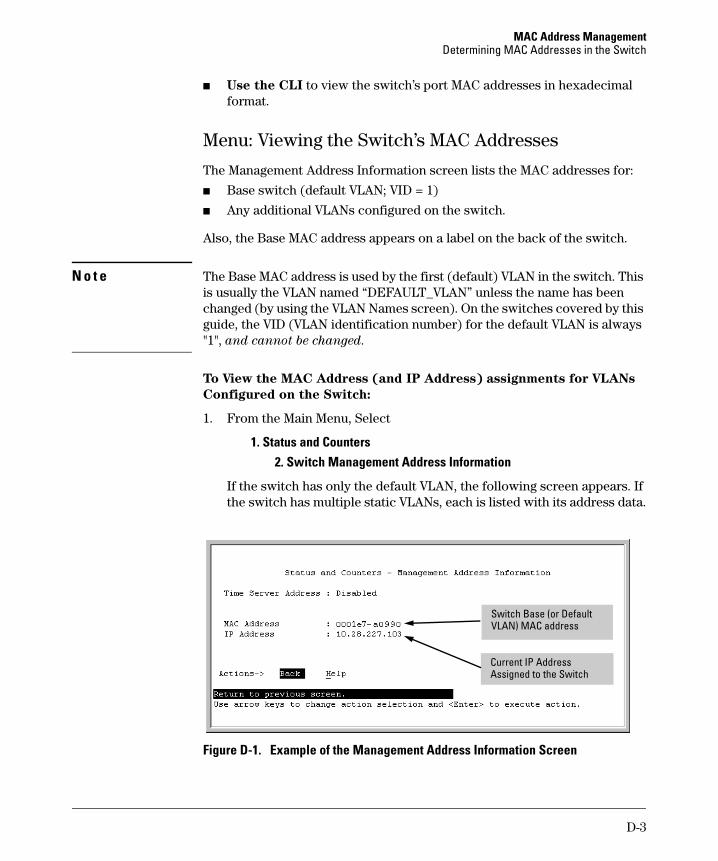
MAC Address Management Determining MAC Addresses in the Switch
■ Use the CLI to view the switch’s port MAC addresses in hexadecimal format.
Menu: Viewing the Switch’s MAC Addresses
The Management Address Information screen lists the MAC addresses for:
■ Base switch (default VLAN; VID = 1)
■ Any additional VLANs configured on the switch.
Also, the Base MAC address appears on a label on the back of the switch.
N o t e The Base MAC address is used by the first (default) VLAN in the switch. This is usually the VLAN named “DEFAULT_VLAN” unless the name has been changed (by using the VLAN Names screen). On the switches covered by this guide, the VID (VLAN identification number) for the default VLAN is always "1", and cannot be changed.
To View the MAC Address (and IP Address) assignments for VLANs
Configured on the Switch:
1. From the Main Menu, Select
1. Status and Counters 2. Switch Management Address Information
If the switch has only the default VLAN, the following screen appears. If the switch has multiple static VLANs, each is listed with its address data.
Switch Base (or Default VLAN) MAC address
Current IP Address Assigned to the Switch
Figure D-1. Example of the Management Address Information Screen
D-3
MAC Address Management Determining MAC Addresses in the Switch
CLI: Viewing the Port and VLAN MAC Addresses
The MAC address assigned to each switch port is used internally by such features as Flow Control and the Spanning Tree Protocol. Using the walkmib command to determine the MAC address assignments for individual ports can sometimes be useful when diagnosing switch operation.
The switch allots 24 MAC addresses per slot. For a given slot, if a three-port module is installed, then the switch uses the first three MAC addresses in the allotment for slot 1, and the remaining 21 MAC addresses are unused. If a six-port module is installed, the switch uses the first six MAC addresses in the allotment, and so-on. The switch’s base MAC address is assigned to VLAN (VID) 1 and appears in the walkmib listing after the MAC addresses for the ports. If multiple VLANs are configured, the MAC addresses assigned to these VLANs appear after the base MAC address.
To display the switch’s MAC addresses, use the walkmib command at the command prompt:
N o t e This procedure displays the MAC addresses for all ports and existing VLANs in the switch, regardless of which VLAN you select.
1. If the switch is at the CLI Operator level, use the enable command to enter the Manager level of the CLI.
2. Type the following command to display the MAC address for each port on the switch:
ProCurve# walkmib ifPhysAddress
(The above command is not case-sensitive.)
For example, with a six-port module in slot 1, a three-port module in slot 3, and three VLANs present:
D-4
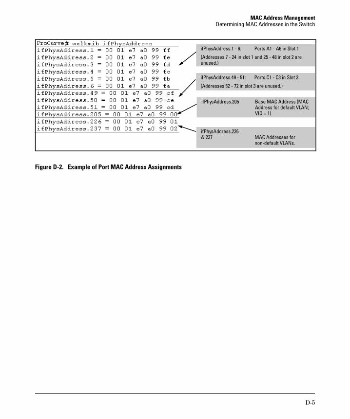
MAC Address Management Determining MAC Addresses in the Switch
& 237
l)
ifPhysAddress.226 MAC Addresses for non-default VLANs.
ifPhysAddress.1 - 6: Ports A1 - A6 in Slot 1
(Addresses 7 - 24 in slot 1 and 25 - 48 in slot 2 are unused.)
ifPhysAddress.49 - 51: Ports C1 - C3 in Slot 3
(Addresses 52 - 72 in slot 3 are unused.)
ifPhysAddress.205 Base MAC Address (MAC Address for defau t VLAN; VID = 1
Figure D-2. Example of Port MAC Address Assignments
D-5
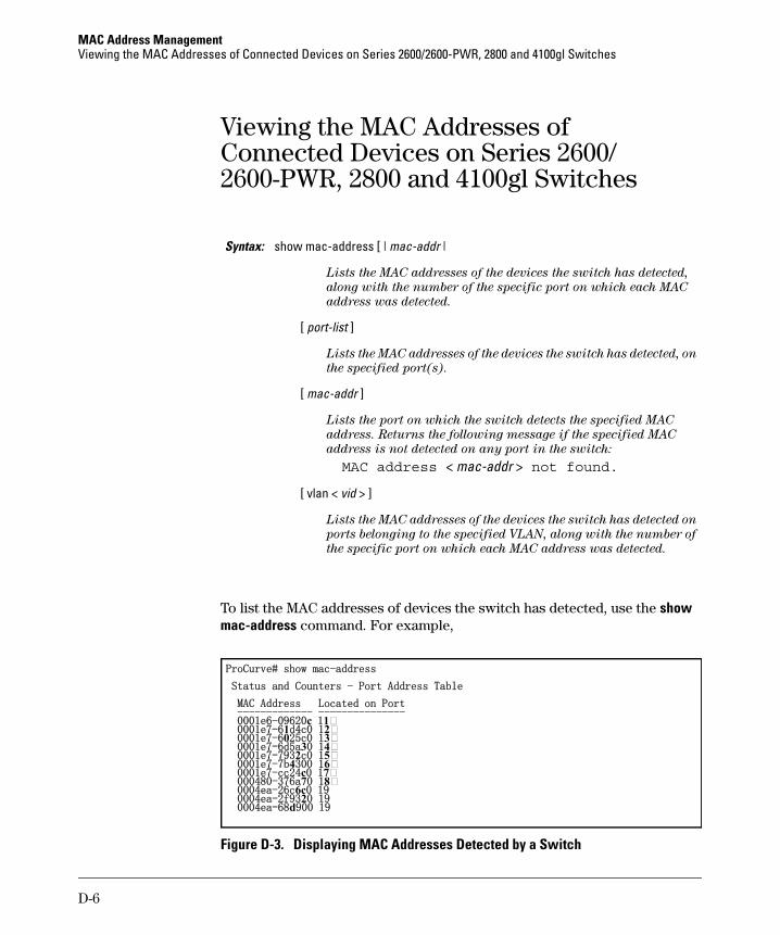
MAC Address Management Viewing the MAC Addresses of Connected Devices on Series 2600/2600-PWR, 2800 and 4100gl Switches
------------- ---------------
Viewing the MAC Addresses of Connected Devices on Series 2600/ 2600-PWR, 2800 and 4100gl Switches
Syntax: show mac-address [ | mac-addr |
Lists the MAC addresses of the devices the switch has detected,
along with the number of the specific port on which each MAC
address was detected.
[ port-list ]
Lists the MAC addresses of the devices the switch has detected, on
the specified port(s).
[ mac-addr ]
Lists the port on which the switch detects the specified MAC
address. Returns the following message if the specified MAC
address is not detected on any port in the switch:
MAC address < mac-addr > not found.
[ vlan < vid > ]
Lists the MAC addresses of the devices the switch has detected on
ports belonging to the specified VLAN, along with the number of
the specific port on which each MAC address was detected.
To list the MAC addresses of devices the switch has detected, use the show mac-address command. For example,
ProCurve# show mac-address
Status and Counters - Port Address Table
MAC Address Located on Port
0001e6-09620c 11 0001e7-61d4c0 12 0001e7-6025c0 13 0001e7-6d5a30 14 0001e7-7932c0 15 0001e7-7b4300 16 0001e7-cc24c0 17 000480-376a70 18 0004ea-26c6c0 19 0004ea-2f9320 19 0004ea-68d900 19
Figure D-3. Displaying MAC Addresses Detected by a Switch
D-6

E
Daylight Savings Time on ProCurve Switches
Configuring Daylight Savings Time
This information applies to the following ProCurve switches:
• 2512 • 3400cl • 1600M • ProCurve • 2524 • 4108gl • 2400M AdvanceStack
• 2626 • 4104gl • 2424M Switches
• 2650 • 6108 • 4000M • ProCurve AdvanceStack Routers
• 2626-PWR • 5304xl • 8000M • 2650-PWR • 5308xl • 212M • 2824 • 224M • 2848
ProCurve switches provide a way to automatically adjust the system clock for Daylight Savings Time (DST) changes. To use this feature you define the month and date to begin and to end the change from standard time. In addition to the value "none" (no time changes), there are five pre-defined settings, named:
■ Alaska
■ Canada and Continental US
■ Middle Europe and Portugal
■ Southern Hemisphere
■ Western Europe
The pre-defined settings follow these rules:
Alaska:
• Begin DST at 2am the first Sunday on or after April 24th.
• End DST at 2am the first Sunday on or after October 25th.
Canada and Continental US:
• Begin DST at 2am the first Sunday on or after April 1st.
E-1
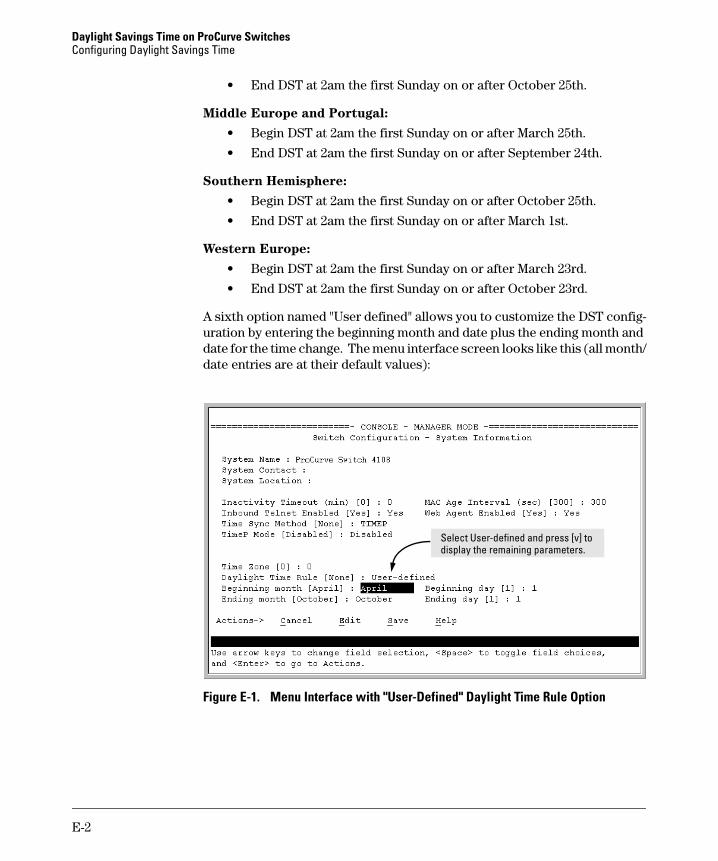
Daylight Savings Time on ProCurve Switches Configuring Daylight Savings Time
• End DST at 2am the first Sunday on or after October 25th.
Middle Europe and Portugal:
• Begin DST at 2am the first Sunday on or after March 25th.
• End DST at 2am the first Sunday on or after September 24th.
Southern Hemisphere:
• Begin DST at 2am the first Sunday on or after October 25th.
• End DST at 2am the first Sunday on or after March 1st.
Western Europe:
• Begin DST at 2am the first Sunday on or after March 23rd.
• End DST at 2am the first Sunday on or after October 23rd.
A sixth option named "User defined" allows you to customize the DST configuration by entering the beginning month and date plus the ending month and date for the time change. The menu interface screen looks like this (all month/ date entries are at their default values):
Select User-defined and press [v] to display the remaining parameters.
Figure E-1. Menu Interface with "User-Defined" Daylight Time Rule Option
E-2

Daylight Savings Time on ProCurve Switches Configuring Daylight Savings Time
Before configuring a "User defined" Daylight Time Rule, it is important to understand how the switch treats the entries. The switch knows which dates are Sundays, and uses an algorithm to determine on which date to change the system clock, given the configured "Beginning day" and "Ending day":
■ If the configured day is a Sunday, the time changes at 2am on that day.
■ If the configured day is not a Sunday, the time changes at 2am on the first Sunday after the configured day.
This is true for both the "Beginning day" and the "Ending day".
With that algorithm, one should use the value "1" to represent "first Sunday of the month", and a value equal to "number of days in the month minus 6" to represent "last Sunday of the month". This allows a single configuration for every year, no matter what date is the appropriate Sunday to change the clock.
E-3

Daylight Savings Time on ProCurve Switches Configuring Daylight Savings Time
— This page is intentionally unused. —
E-4
Index
Symbols
=> prompt … C-44
Numerics
802.1x LLDP blocked … 13-31
802.1X effect, LLDP … 13-49802.3u auto negotiation standard … 10-4
A
accessmanager … 13-13operator … 13-13
Actions line … 3-9, 3-10, 3-11location on screen … 3-9
address table, port … B-14address, network manager … 13-4, 13-5alert log … 5-19
alert types … 5-20disabling … 5-24setting the sensitivity level … 5-23sorting the entries … 5-19
applicable products … 1-iiasterisk … 3-10, 3-13authentication trap … 13-20, 13-23
See also SNMP.authentication trap, configuring … 13-23authorized IP managers
SNMP, blocking … 13-3auto MDI/MDI-X configuration, display … 10-15auto MDI/MDI-X operation … 10-15auto MDI/MDI-X port mode, display … 10-15auto negotiation … 10-4, 10-5Auto-10 … 12-5, 12-8auto-discovery … 13-5
B
bandwidthdisplaying utilization … 5-16
booteffect on configuration … 3-13
See also reboot.boot ROM console … A-3boot ROM mode … C-44Bootp
Bootp table file … 8-14Bootptab file … 8-14effect of no reply … C-8operation … 8-14using with Unix systems … 8-14
Bootp/DHCP, LLDP … 13-40broadcast limit … 10-6, 10-11broadcast storm … 12-5, C-15browser interface
See web browser interface.
C
CDPconfiguration, viewing … 13-52data collection … 13-51default CDP operation … 13-51disabled … 13-51general operation … 13-52mappings to LLDP data fields … 13-50neighbor devices … 13-51neighbors table … 13-53on individual ports … 13-54read-only operation … 13-50, 13-51
chassis over-temperatureSee temperature
Class of Servicepriority settings mapped to downstream
devices … 10-29Clear button … 5-11
restoring factory default configuration … C-43CLI
context level … 10-11command line interface
See CLI.communities, SNMP … 13-14
viewing and configuring with the CLI … 13-16viewing and configuring with the menu … 13-14
Index – 1

configuration … 3-7Bootp … 8-14comparing startup to running … 6-5console … 7-3copying … A-18download … A-3factory default … 6-8, 8-2IP … 8-3network monitoring … B-24permanent … 6-6permanent change defined … 6-4port … 10-1, 12-1port trunk groups … 10-1, 12-1quick … 3-8reboot to activate … 3-13restoring factory defaults … C-43saving from menu interface … 3-10serial link … 7-3SNMP … 13-4, 13-5, 13-12SNMP communities … 13-14, 13-16startup … 3-10system … 7-10Telnet access configuration … 7-3transferring … A-18trap receivers … 13-20viewing … 6-5web browser access … 7-3
configuration filebrowsing for troubleshooting … C-39
console … C-8configuring … 7-3ending a session … 3-5features … 2-3Main menu … 3-7navigation … 3-9, 3-10operation … 3-10starting a session … 3-4status and counters access … 3-7troubleshooting access problems … C-6
context level global config … 8-11
copyright … 1-iiCPU utilization … B-6
D
date format … C-23date, configure … 7-14
debug command"debug" severity and Syslog servers … C-34event … C-28event log … C-33syntax … C-28
debug loggingconfiguration, viewing … C-32general operation … C-27session, not current … C-33status, viewing … C-32Syslog configuration … C-29Syslog logging disabled … C-29Syslog server, view configuration … C-32Syslog, number of servers … C-27Telnet session … C-27
debug logging, LLDP … 13-29default gateway … 8-3default trunk type … 12-11Device Passwords Window … 5-8DHCP
address problems … C-8configuring DHCP relay … 8-12effect of no reply … C-8Option 82 … 8-12setting up a DHCP helper … 8-12
DHCP/Bootpoperation … 8-12process … 8-13
DHCP/Bootp, LLDP … 13-40diagnostics tools … C-34
browsing the configuration file … C-39ping and link tests … C-35
disclaimer … 1-iiDNS name … 5-4Domain Name Server … 5-4download
switch-to-switch … A-14troubleshooting … A-17Xmodem … A-11
download OS … A-14download, TFTP … A-3, A-4downstream device (QoS)
effect of priority settings … 10-29duplicate MAC address
See MAC addressDyn1
See LACP.
2 – Index

E
ending a console session … 3-5event log … 3-7, C-23
navigation … C-25PoE messages … 11-14See also debug logging.severity level … C-23temperature messages … C-5use during troubleshooting … C-23with debug … C-33
excessive packets … 10-24
F
factory default configuration restoring … 6-8, C-43
failure, OS download … A-17fan failure … C-5fault detection … 5-8
policy … 5-8setting the policy … 5-23window … 5-23
fault detection policy … 5-23fault-tolerance … 12-5filter, source-port … 10-23firmware version … B-6flash memory … 3-10, 6-2flow control … 10-5
jumbo packets … 10-18, 10-22flow control, status … B-10flow control, terminal … 7-3format, date … C-23format, time … C-23friendly port names
See port names, friendly.
G
gateway … 8-3, 8-5gateway (IP) address … 8-4, 8-6giant packets … 10-24global config level, CLI … 8-11
H
Help … 3-11, 5-13location on menu screen … 3-9online inoperable … 5-13
I
IEEE 802.1AB-2005 … 13-30IEEE 802.1d … C-15IEEE 802.3ab … 10-5IGMP
host not receiving … C-9not working … C-9statistics … B-20
inactivity timeout … 7-4Inbound Telnet Enabled parameter … C-7Inconsistent value … 13-36invalid input … 4-13IP
CLI access … 8-7configuration … 8-3DHCP/Bootp … 8-3duplicate address … C-8duplicate address, DHCP network … C-8effect when address not used … 8-11gateway … 8-3gateway (IP) address … 8-4menu access … 8-5multinetting … 8-9multiple addresses in VLAN … 8-9stacking … 8-5subnet … 8-9subnet mask … 8-3, 8-6subnetting … 8-9using for web browser interface … 5-4web access … 8-11
IP addressfor SNMP management … 13-3multiple in a VLAN … 8-9removing or replacing … 8-10
IP preserveDHCP server … 8-16overview … 8-16rules, operating … 8-16summary of effect … 8-19
IPXnetwork number … B-7
J
Java … 5-4Java applets … 5-5jumbo packets
configuration … 10-19
Index – 3
L
excessive inbound … 10-23flow control … 10-18, 10-22GVRP operation … 10-18management VLAN … 10-22maximum size … 10-17MTU … 10-17port adds and moves … 10-18port speed … 10-18security concerns … 10-23standard MTU … 10-18through non-jumbo ports … 10-24traffic sources … 10-18troubleshooting … 10-24VLAN tag … 10-17voice VLAN … 10-22
K
kill command … 7-9
LACP802.1x, not allowed … 12-23active … 12-16, 12-20CLI access … 12-12default port operation … 12-21described … 12-7, 12-18Dyn1 … 12-8dynamic … 12-20enabling dynamic trunk … 12-16full-duplex required … 10-5, 12-5, 12-18IGMP … 12-24no half-duplex … 12-25operation not allowed … C-10outbound traffic distribution … 12-26overview … 12-5passive … 12-16, 12-20removing port from active trunk … 12-17restrictions … 12-23standby link … 12-20status, terms … 12-22STP … 12-24VLANs … 12-24with 802.1x … 12-23with port security … 12-23
learning bridge … 8-2limit, broadcast … 10-11
link speed, port trunk … 12-3link test
description … C-35for troubleshooting … C-35
link, serial … 7-3LLDP
802.1D-compliant switch … 13-49802.1x blocking … 13-31802.1X effect … 13-49active port … 13-26advertisement … 13-26advertisement content … 13-39advertisement data … 13-41advertisement, mandatory data … 13-39advertisement, optional data … 13-40advertisements, delay interval … 13-36CDP neighbor data
CDP
LLDP neighbor data … 13-50chassis ID … 13-39chassis type … 13-39clear statistics counters … 13-46comparison with CDP data fields … 13-50configuration options … 13-27data options … 13-28data read options … 13-30data unit … 13-26debug logging … 13-29default … 13-51default configuration … 13-32DHCP/Bootp operation … 13-31disable, per-port … 13-39display neighbor data … 13-43enable/disable, global … 13-34general operation … 13-27global counters … 13-46holdtime multiplier … 13-35hub, packet-forwarding … 13-27IEEE 802.1AB-2005 … 13-26, 13-30Inconsistent value … 13-36information options … 13-28invalid frames … 13-47IP address advertisement … 13-31IP address subelement … 13-39IP address, advertisement … 13-49IP address, DHCP/Bootp … 13-40IP address, options … 13-39IP address, version advertised … 13-39
4 – Index

LLDP-aware … 13-26LLDPDU … 13-26MIB … 13-27, 13-30neighbor … 13-26neighbor data remaining … 13-49neighbor data, displaying … 13-43neighbor statistics … 13-46neighbor, maximum … 13-49operating rules … 13-31optional data, configuring … 13-41packet boundaries … 13-27packet dropped … 13-27packet time-to-live … 13-29packet-forwarding … 13-27packets not forwarded … 13-26per-port counters … 13-47port description … 13-40port ID … 13-39port trunks … 13-31port type … 13-39refresh interval … 13-35reinitialization delay … 13-37remote management address … 13-29remote manager address … 13-39reset counters … 13-46rxonly … 13-39setmib, delay interval … 13-36setmib, reinit delay … 13-37show advertisement data … 13-41show commands … 13-32, 13-33show outbound advertisement … 13-42SNMP notification … 13-28spanning-tree blocking … 13-31standards compatibility … 13-30statistics, displaying … 13-46system capabilities … 13-40system description … 13-40system name … 13-40terminology … 13-26time-to-live … 13-27, 13-35TLV … 13-26transmission frequency … 13-27transmission interval, change … 13-35transmit/receive modes … 13-28transmit/receive modes, per-port … 13-39trap notice interval … 13-38trap notification … 13-37trap receiver, data change notice … 13-37
TTL … 13-27, 13-29txonly … 13-39VLAN, untagged … 13-49walkmib … 13-30
LLDPDU … 13-26load balancing
See port trunk.logical port … 12-9loop, network … 12-5lost password … 5-11
M
MAC address … 8-14, B-6, D-2duplicate … C-15, C-21learned … B-13, B-14listing connected devices … D-6port … D-2, D-3switch … D-2VLAN … D-2
managementserver URL … 5-12, 5-13server URL default … 5-13
management VLAN See VLAN.
manager access … 13-13manager password … 5-8, 5-10MDI/MDI-X configuration, display … 10-15MDI/MDI-X port mode, display … 10-15media type, port trunk … 12-3memory
flash … 3-10, 6-2startup configuration … 3-10
menu interfaceconfiguration changes, saving … 3-10
MIB … 13-4MIB listing … 13-4MIB, HP proprietary … 13-4MIB, standard … 13-4mirroring
See port monitoring.monitoring traffic … B-24multinetting … 8-9multinetting, limit … 8-9multiple VLAN … 13-3multi-port bridge … 8-2
Index – 5

N
navigation, console interface … 3-9, 3-10navigation, event log … C-25network management functions … 13-5network manager address … 13-4, 13-5network monitoring
traffic overload … B-24Network Monitoring Port screen … B-24network slow … C-8Not Current One, debug session … C-33notices … 1-ii
O
online help … 5-13online help location … 5-13operation not allowed, LACP … C-10operator access … 13-13operator password … 5-8, 5-10OS
version … A-5, A-12, A-15OS download
failure indication … A-17switch-to-switch download … A-14troubleshooting … A-17using TFTP … A-3
out-of-band … 2-3over-temperature
See temperature
P
password … 5-8, 5-10creating … 5-8delete … 3-7, 5-11if you lose the password … 5-11lost … 5-11manager … 5-8operator … 5-8set … 3-7setting … 5-9using to access browser and console … 5-10
ping testdescription … C-35for troubleshooting … C-35
PoECLI commands … 11-7configuring … 11-7
disabling a port … 11-8event log messages … 11-14operation on ProCurve switches … 11-2planning and implementation … 11-13port priority … 11-5power supplies … 11-3pre-802.3af-standard devices … 11-9priority class … 11-3viewing power status … 11-10
portaddress table … B-14auto negotiation … 10-4, 10-5broadcast limit … 10-11CLI access … 10-7context level … 10-11control configuration … 10-1, 12-1counters … B-10counters, reset … B-10fiber-optic … 10-5full-duplex, LACP … 10-5MAC address … D-3, D-4menu access … 10-6queues
See port-based priority.traffic patterns … B-10trunk
See port trunk.utilization … 5-16
web browser interface … 5-16web browser access … 10-17
port names, friendlyconfiguring … 10-34displaying … 10-36summary … 10-33
port securityport trunk restriction … 12-4trunk restriction … 12-9
port trunk … 12-2caution … 12-5, 12-10, 12-17CLI access … 12-12default trunk type … 12-11enabling dynamic LACP … 12-16IGMP … 12-9LACP … 10-5LACP, full duplex required … 12-5link requirements … 12-3logical port … 12-9media requirements … 12-8
6 – Index
media type … 12-3menu access to static trunk … 12-10monitor port restrictions … 12-9nonconsecutive ports … 12-2number of trunks … 12-5port groups for Series 2800 … 12-3, 12-4, 12-8port groups for Series 4100 10/100/1000
Module … 12-9port security restriction … 12-9removing port from static trunk … 12-16requirements … 12-8SA/DA … 12-26See also LACP.Series 2800 boundary … 12-3, 12-4, 12-8Series 4100 10/100/1000 Module
boundary … 12-9spanning tree protocol … 12-9static trunk … 12-8static trunk, overview … 12-5STP … 12-9STP operation … 12-8traffic distribution … 12-8Trk1 … 12-8trunk (non-protocol) option … 12-7trunk option described … 12-25types … 12-7VLAN … 12-9VLAN operation … 12-8web browser access … 12-18
port trunk group interface access … 10-1, 12-1
port, active … 13-26port-based access control
event log … C-10LACP not allowed … 12-23troubleshooting … C-10
port-based priority802.1q VLAN tagging … 10-28configuring … 10-31messages … 10-32outbound port queues … 10-29overview … 10-28priority/queue table … 10-29requirement for continuity … 10-30rules of operation … 10-30troubleshooting … 10-32viewing configuration … 10-31
power interruption, effect on event log … C-23
power over ethernet See PoE.
ProCurve Networking support URL … 5-13
prompt, => … C-44public SNMP community … 13-5publication data … 1-ii
Q
quick configuration … 3-8quick start … 1-6, 8-4
R
reboot … 3-8, 3-10, 3-12reboot, actions causing … 6-3reboot, effect on configuration … 3-13reconfigure … 3-10remote session, terminate … 7-9reset … 3-12, 6-10Reset button
restoring factory default configuration … C-43reset port counters … B-10resetting the switch
factory default reset … C-43restricted access … 13-14restricted write access … 13-13RFC
See MIB.RFC 1493 … 13-4RFC 1515 … 13-4RFC 2922 … 13-30RFC2737 … 13-30RFC2863 … 13-30RMON … 13-4router
gateway … 8-6RS-232 … 2-3 running-config, viewing … 6-5
See also configuration.
S
SCP/SFTPsession limit … A-10
secure copySee SCP/SFTP.
Index – 7

secure FTP broadcast mode … 9-2, 9-9 See SCP/SFTP. broadcast mode, requirement … 9-3
security … 5-11, 7-3 configuration … 9-4 Self Test LED disabling … 9-11
behavior during factory default reset … C-43 enabling and disabling … 9-9 serial number … B-6 event log messages … 9-24 session menu interface operation … 9-24
See debug logging. operating modes … 9-2 setmib, delay interval … 13-36 poll interval … 9-12 setmib, reinit delay … 13-37 See also TimeP. setting fault detection policy … 5-23 selecting … 9-3 setup screen … 1-6, 8-4 unicast mode … 9-3, 9-10 severity code, event log … C-23 unicast time polling … 9-21 show tech … C-40 unicast, address priority … 9-22 slow network … C-8 unicast, deleting addresses … 9-23 SNMP … 13-3 unicast, replacing servers … 9-23
CLI commands … 13-13 viewing … 9-4, 9-8 communities … 13-4, 13-5, 13-12, 13-13, 13-14 software version … B-6 configure … 13-4, 13-5 sorting alert log entries … 5-19 IP … 13-3 source-port filter … 10-23 notification, LLDP spanning tree
SNMP notification … 13-28 configuration … 10-10 public community … 13-5, 13-14 fast-uplink restricted access … 13-14 troubleshooting … C-15 thresholds … 13-20 global information … B-18 traps … 13-4, 13-20 information screen … B-18 traps, well-known … 13-20 problems related to … C-15
SNMP communities show tech, copy output … C-40 configuring with the CLI … 13-16 statistics … B-18 configuring with the menu … 13-14 using with port trunking … 12-9
SNMP trap, LLDP … 13-37 viewing port operating statistics … 10-10 SNMPv3 SSH
"public" community access caution … 13-6 debug logging … C-27 access … 13-5 TACACS exclusion … A-10 assigning users to groups … 13-8 troubleshooting … C-16 communities … 13-12 standard MIB … 13-4 enable command … 13-7 starting a console session … 3-4 enabling … 13-6 startup-config, viewing … 6-5 group access levels … 13-11, 13-12 See also configuration. groups … 13-10 statistics … 3-7, B-4 network management problems with snmpv3 statistics, clear counters … 3-12, 6-10
only … 13-6 status and counters notification … 13-18 access from console … 3-7 restricted-access option … 13-6 status and counters menu … B-5 set up … 13-5 status overview screen … 5-6 traps … 13-18 subnet … 8-9 users … 13-5 subnet mask … 8-5, 8-6
SNTP … 9-3 See also IP.
8 – Index

subnetting … 8-9support
changing default URL … 5-13URL … 5-12URL Window … 5-12
switch consoleSee console.
switch setup menu … 3-8switch software
See OS.switch-to-switch download … A-14Syslog
facility, user … C-34See debug logging.severity, "debug" … C-34
system configuration screen … 7-10System Name parameter … 7-11
T
TACACSSSH exclusion … A-10
Telnet … 3-4terminate session, kill command … 7-9
Telnet, enable/disable … 7-4Telnet, outbound … 7-6Telnet, problem … C-7temperature
fan failure … C-5messages … C-5
terminal access, lose connectivity … 7-6terminal mode, changing dynamically … 7-8terminal type … 7-3 terminate remote session … 7-9TFTP
download … A-4OS download … A-3
threshold setting … 13-5thresholds, SNMP … 13-20time format … C-23time protocol
selecting … 9-3time server … 8-3time, configure … 7-14TimeP … 8-4, 8-5
assignment methods … 9-2disabling … 9-20enabling and disabling … 9-18
poll interval … 9-20selecting … 9-3viewing and configuring, menu … 9-15viewing, CLI … 9-17
timesync, disabling … 9-20Time-To-Live … 8-4, 8-5time-to-live, LLDP … 13-27traffic monitoring … 13-5, B-24traffic, port … B-10transceiver, fiber-optic … 10-5trap … 5-24
authentication … 13-20authentication trap … 13-23CLI access … 13-20event levels … 13-22limit … 13-20receiver … 13-20SNMP … 13-20
trap notification … 13-37trap receiver … 13-4, 13-5
configuring … 13-20, 13-22troubleshooting
approaches … C-3browsing the configuration file … C-39console access problems … C-6diagnosing unusual network activity … C-8diagnostics tools … C-34fast-uplink … C-15OS download … A-17ping and link tests … C-35restoring factory default configuration … C-43spanning tree … C-15SSH … C-16switch won’t reboot, shows => prompt … C-44unusual network activity … C-8using the event log … C-23web browser access problems … C-6
trunkSee port trunk.
TTL … 8-4, 8-5TTL, LLDP … 13-27types of alert log entries … 5-20
U
unauthorized access … 13-23undersize packets … 10-24Unix, Bootp … 8-14
Index – 9

V
unrestricted write access … 13-13unusual network activity … C-8up time … B-6URL
browser interface online help location … 5-13management … 5-13management server … 5-12, 5-13ProCurve Networking … 5-13support … 5-12, 5-13
user name, using for browser or console access … 5-8, 5-10
users, SNMPv3See SNMPv3.
using the passwords … 5-10utilization, port … 5-16
version, OS … A-5, A-12, A-15VLAN … 8-4, C-21, D-2
address … 13-3Bootp … 8-14configuring Bootp … 8-14device not seen … C-20event log entries … C-23link blocked … C-15management and jumbo packets … 10-22management VLAN, SNMP block … 13-3monitoring … B-3multinetting … 8-9multiple … 13-3multiple IP addresses … 8-9OS download … A-3port configuration … C-20primary … 8-4reboot required … 3-8subnet … 8-9support enable/disable … 3-8tagging broadcast, multicast, and unicast
traffic … C-20VLAN ID … 4-15
See also VLAN.VT-100 terminal … 7-3
W
walkmib … 13-30warranty … 1-ii
web agent advantages … 2-5enabled … 5-2
web browser access configuration … 7-3web browser enable/disable … 7-4web browser interface
access parameters … 5-8alert log … 5-6, 5-19alert log details … 5-20bandwidth adjustment … 5-17bar graph adjustment … 5-17disable access … 5-2enabling … 5-4error packets … 5-16fault detection policy … 5-8, 5-23fault detection window … 5-23features … 2-5first-time install … 5-7first-time tasks … 5-7main screen … 5-15online help … 5-13online help location specifying … 5-13online help, inoperable … 5-13overview … 5-15Overview window … 5-15password lost … 5-11password, setting … 5-9port status … 5-18port utilization … 5-16port utilization and status displays … 5-16screen elements … 5-15security … 5-2, 5-8standalone … 5-4status bar … 5-22status indicators … 5-22status overview screen … 5-6system requirements … 5-4troubleshooting access problems … C-6URL default … 5-13URL, management server … 5-14URL, support … 5-14
web site, ProCurve Networking … 13-4write access … 13-13write memory, effect on menu interface … 3-13
X
Xmodem OS download … A-11
10 – Index

— This page is intentionally unused. —

Technical information in this document is subject to change without notice.
© Copyright 2000-2005 Hewlett-Packard Development Company, L.P. All rights reserved. Reproduction, adaptation, or translation without prior written permission is prohibited except as allowed under the copyright laws.
September 2005
Manual Part Number 5990-8867