switch actuator reg-k/12x230/10 with manual …€¦ · as of 01/07 2 chapter 7: switch actuators...
TRANSCRIPT
As of 01/07 1
Chapter 7: Switch actuators
7.6 Switch actuator, 12-gang Switch actuator REG-K/12x230/10 with manual mode
Art. No. 649212
Switch actuator REG-K/12x230/10 with manual modeChapter 7:Switch actuatorsArt. No.649212As of 01/077.6Switch actuator, 12-gang
1. Function 12. Installation 23. Operation 34. Recognising and rectifying faults 45. Technical data 56. Settings in the EIB Tool Software (ETS) 67.1 Switch Logic Time Scene Dis. Prio. Init. 4820/
1.1 7Introduction 7Switching settings 8Device functions 20Parameters and settings 27
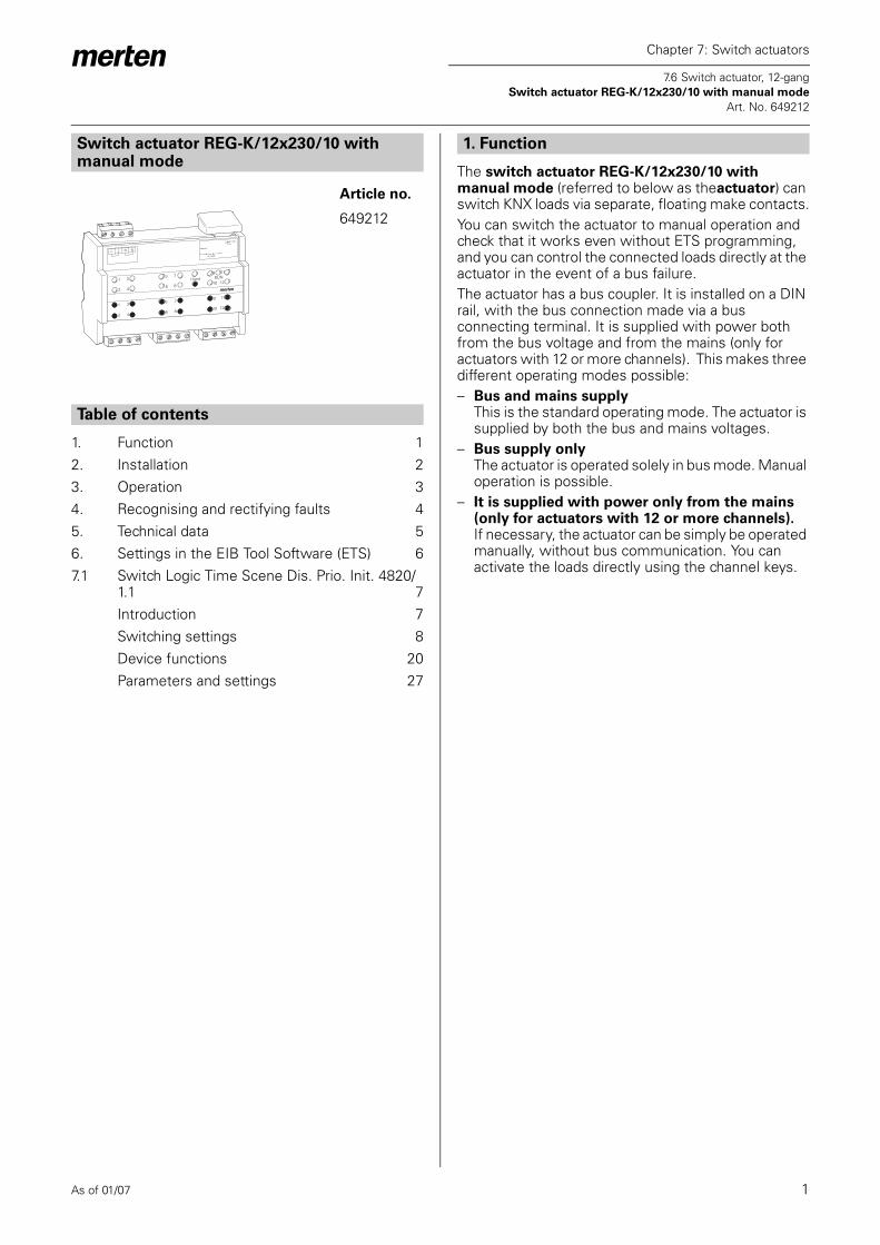
The switch actuator REG-K/12x230/10 with manual mode (referred to below as theactuator) can switch KNX loads via separate, floating make contacts.You can switch the actuator to manual operation and check that it works even without ETS programming, and you can control the connected loads directly at the actuator in the event of a bus failure.The actuator has a bus coupler. It is installed on a DIN rail, with the bus connection made via a bus connecting terminal. It is supplied with power both from the bus voltage and from the mains (only for actuators with 12 or more channels). This makes three different operating modes possible:– Bus and mains supply
This is the standard operating mode. The actuator is supplied by both the bus and mains voltages.
– Bus supply onlyThe actuator is operated solely in bus mode. Manual operation is possible.
– It is supplied with power only from the mains (only for actuators with 12 or more channels). If necessary, the actuator can be simply be operated manually, without bus communication. You can activate the loads directly using the channel keys.
Switch actuator REG-K/12x230/10 with manual mode
Article no.
649212
Table of contents
Hand RUN
address:
0A 5090
BUS LEDProg.
L L N N
1 3 5 79 11
2 4 6 810 12
1 3 5 79 11
2 4 6 810 12
1. Function
As of 01/07 2
Chapter 7: Switch actuators
7.6 Switch actuator, 12-gang Switch actuator REG-K/12x230/10 with manual mode
Art. No. 649212
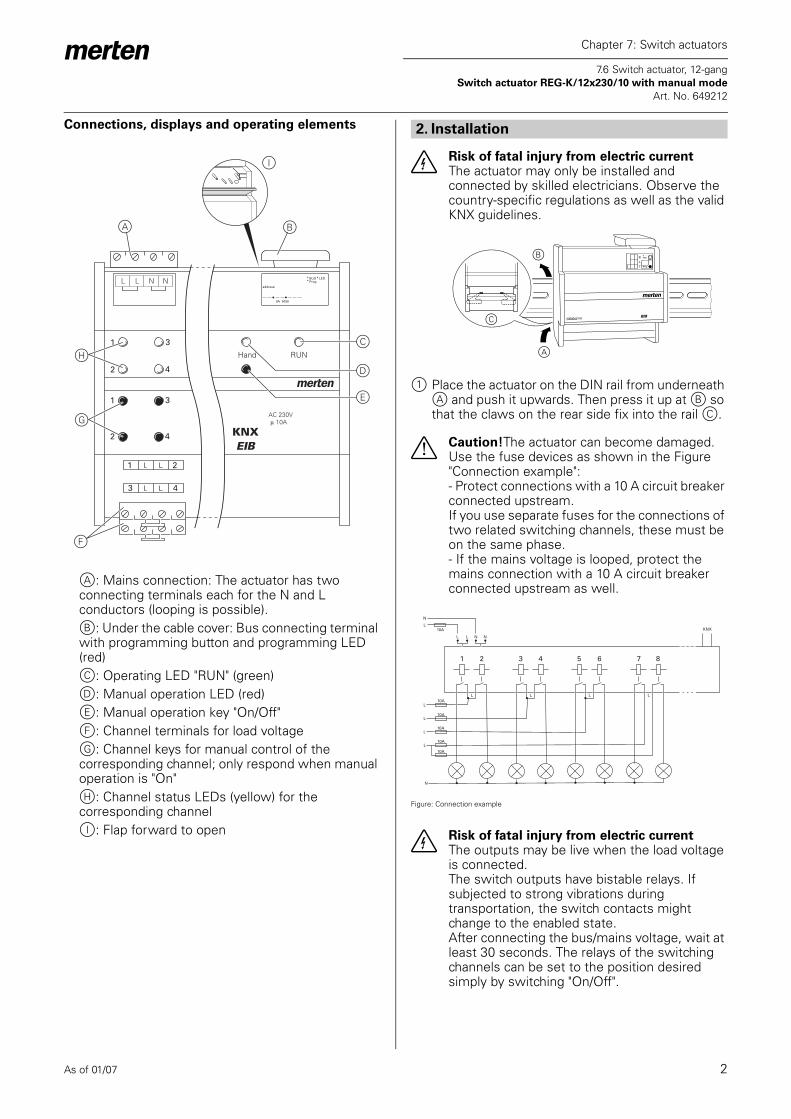
Connections, displays and operating elements
A: Mains connection: The actuator has two connecting terminals each for the N and L conductors (looping is possible).B: Under the cable cover: Bus connecting terminal with programming button and programming LED (red)C: Operating LED "RUN" (green)D: Manual operation LED (red)E: Manual operation key "On/Off"F: Channel terminals for load voltageG: Channel keys for manual control of the corresponding channel; only respond when manual operation is "On"H: Channel status LEDs (yellow) for the corresponding channelI: Flap forward to open
¼ Risk of fatal injury from electric currentThe actuator may only be installed and connected by skilled electricians. Observe the country-specific regulations as well as the valid KNX guidelines.
1 Place the actuator on the DIN rail from underneath A and push it upwards. Then press it up at B so that the claws on the rear side fix into the rail C.
½ Caution!The actuator can become damaged. Use the fuse devices as shown in the Figure "Connection example":- Protect connections with a 10 A circuit breaker connected upstream.If you use separate fuses for the connections of two related switching channels, these must be on the same phase.- If the mains voltage is looped, protect the mains connection with a 10 A circuit breaker connected upstream as well.
Figure: Connection example
¼ Risk of fatal injury from electric currentThe outputs may be live when the load voltage is connected.The switch outputs have bistable relays. If subjected to strong vibrations during transportation, the switch contacts might change to the enabled state.After connecting the bus/mains voltage, wait at least 30 seconds. The relays of the switching channels can be set to the position desired simply by switching "On/Off".
Hand RUN
KNXEIB
L L N N
1 2
3 4
1 3
2 4
1 3
2 4
A B
C
D
E
H
I
G
F
address:
0A 5090
BUS LEDProg.
2. Installation
A
B
C
L
L
L
L10A
10A
N
N
N
KNX
L
L
L
L
N
L
10A
L L
10A
10A
10A
1 2 3 4 5 6 7 8
As of 01/07 3
Chapter 7: Switch actuators
7.6 Switch actuator, 12-gang Switch actuator REG-K/12x230/10 with manual mode
Art. No. 649212
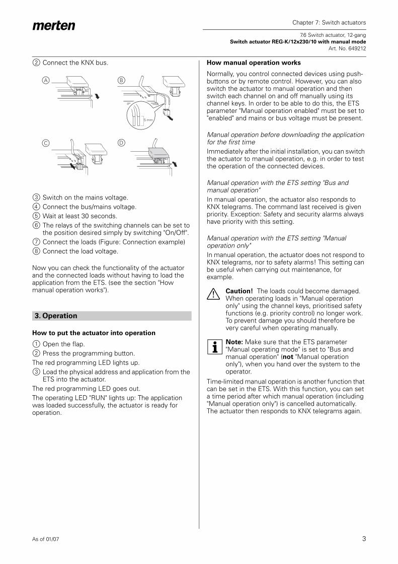
2 Connect the KNX bus.
3 Switch on the mains voltage.4 Connect the bus/mains voltage.5 Wait at least 30 seconds.6 The relays of the switching channels can be set to
the position desired simply by switching "On/Off".7 Connect the loads (Figure: Connection example)8 Connect the load voltage.
Now you can check the functionality of the actuator and the connected loads without having to load the application from the ETS. (see the section "How manual operation works").
How to put the actuator into operation
1 Open the flap.2 Press the programming button.The red programming LED lights up.3 Load the physical address and application from the
ETS into the actuator.The red programming LED goes out.The operating LED "RUN" lights up: The application was loaded successfully, the actuator is ready for operation.
How manual operation works
Normally, you control connected devices using push-buttons or by remote control. However, you can also switch the actuator to manual operation and then switch each channel on and off manually using its channel keys. In order to be able to do this, the ETS parameter "Manual operation enabled" must be set to "enabled" and mains or bus voltage must be present.
Manual operation before downloading the application for the first timeImmediately after the initial installation, you can switch the actuator to manual operation, e.g. in order to test the operation of the connected devices.
Manual operation with the ETS setting "Bus and manual operation"In manual operation, the actuator also responds to KNX telegrams. The command last received is given priority. Exception: Safety and security alarms always have priority with this setting.
Manual operation with the ETS setting "Manual operation only"In manual operation, the actuator does not respond to KNX telegrams, nor to safety alarms! This setting can be useful when carrying out maintenance, for example.
½ Caution! The loads could become damaged. When operating loads in "Manual operation only" using the channel keys, prioritised safety functions (e.g. priority control) no longer work. To prevent damage you should therefore be very careful when operating manually.
| Note: Make sure that the ETS parameter "Manual operating mode" is set to "Bus and manual operation" (not "Manual operation only"), when you hand over the system to the operator.
Time-limited manual operation is another function that can be set in the ETS. With this function, you can set a time period after which manual operation (including "Manual operation only") is cancelled automatically. The actuator then responds to KNX telegrams again.
3. Operation
5 mm
A B
C D
As of 01/07 4
Chapter 7: Switch actuators
7.6 Switch actuator, 12-gang Switch actuator REG-K/12x230/10 with manual mode
Art. No. 649212
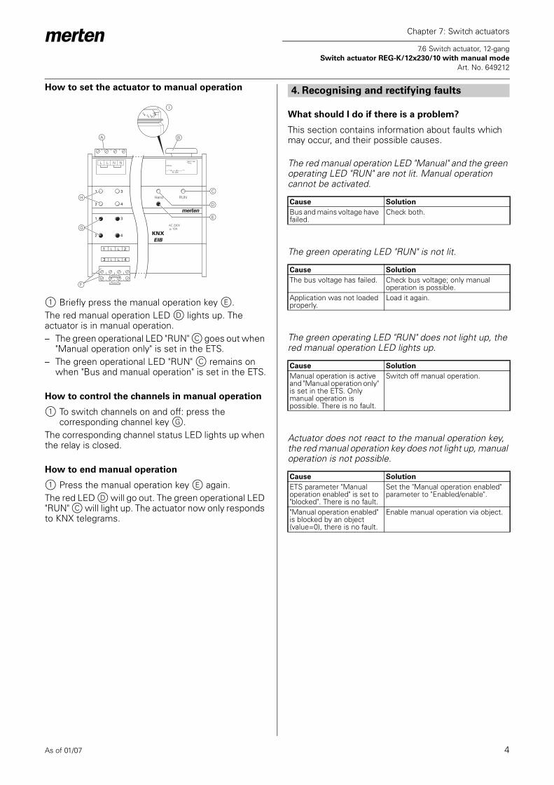
How to set the actuator to manual operation
1 Briefly press the manual operation key E.The red manual operation LED D lights up. The actuator is in manual operation.– The green operational LED "RUN" C goes out when
"Manual operation only" is set in the ETS.– The green operational LED "RUN" C remains on
when "Bus and manual operation" is set in the ETS.
How to control the channels in manual operation
1 To switch channels on and off: press the corresponding channel key G.
The corresponding channel status LED lights up when the relay is closed.
How to end manual operation
1 Press the manual operation key E again.The red LED D will go out. The green operational LED "RUN" C will light up. The actuator now only responds to KNX telegrams.
What should I do if there is a problem?
This section contains information about faults which may occur, and their possible causes.
The red manual operation LED "Manual" and the green operating LED "RUN" are not lit. Manual operation cannot be activated.
The green operating LED "RUN" is not lit.
The green operating LED "RUN" does not light up, the red manual operation LED lights up.
Actuator does not react to the manual operation key, the red manual operation key does not light up, manual operation is not possible.
Hand RUN
KNXEIB
L L N N
1 2
3 4
1 3
2 4
1 3
2 4
A B
C
D
E
H
I
G
F
address:
0A 5090
BUS LEDProg.
4. Recognising and rectifying faults
Cause Solution
Bus and mains voltage have failed.
Check both.
Cause Solution
The bus voltage has failed. Check bus voltage; only manual operation is possible.
Application was not loaded properly.
Load it again.
Cause Solution
Manual operation is active and "Manual operation only" is set in the ETS. Only manual operation is possible. There is no fault.
Switch off manual operation.
Cause Solution
ETS parameter "Manual operation enabled" is set to "blocked". There is no fault.
Set the "Manual operation enabled" parameter to "Enabled/enable".
"Manual operation enabled" is blocked by an object (value=0), there is no fault.
Enable manual operation via object.

As of 01/07 5
Chapter 7: Switch actuators
7.6 Switch actuator, 12-gang Switch actuator REG-K/12x230/10 with manual mode
Art. No. 649212
In manual operation, the actuator does not react to the activation of the channel keys, the red manual operation LED lights up, manual mode is not possible.
In manual operation, the actuator controls connected loads without a channel key being pressed.
When and how the LEDs light up
Statuses of the LEDs relative to the supply voltage
Cause Solution
The green operational LED "RUN" is still lit:The ETS parameter "Manual operating mode" is set to "Bus and manual operation", a prioritised function (e.g. lock) is activated, there is no fault.
Wait until the higher-level function has been completed, or switch the ETS parameter "Manual operation type" to "Manual operation only". Observe the safety note in the section "How manual operation works".
The green operating LED "RUN" is not lit:The bus voltage has failed and the ETS parameter "Manual operation when bus voltage fails" is set to "blocked".
Check the bus voltage.
Cause Solution
ETS parameter "Manual operating mode" is set to "Bus and manual operation". The control command for the actuator came via a KNX telegram. There is no fault.
Switch the ETS parameter "Manual operating mode" to "Manual operation only". Observe the safety note in the section "How manual operation works".
RUN(green)
Manual(red)
Channel status(yellow)
On - - Normal operation
- On - Manual operation (ETS: manual operation only)
On On - Manual operation (ETS: Bus and manual operation)
RUN(green)
Manual(red)
Channel status(yellow)
On lights up on manual operation
lights up when activated
Mains and bus voltage or bus voltage only
- lights up on manual operation
lights up when activated
mains voltage only
5. Technical data
External auxiliary voltage:
AC 110–240 V, 50–60 Hz, max. 2 VA
Supply from KNX:DC 24 V, max. 17.5 mA
Nominal voltage: AC 230 V
For each switch output
Nominal current: 10 A, ohmic load cos ϕ = 110 A, inductive load cosϕ = 0.6
Capacitive load: 10 A, max. 105 μFIncandescent lamps: AC 230 V, max. 2000 WHalogen lamps: AC 230 V, max. 1700 WLV halogen lamps with wound transformer: AC 230 V, 250 VAFluorescent lamps: AC 230 V, max. 1800 W,
uncompensatedAC 230 V, max. 1000 W parallel-compensated
Motor load: AC 230 V, max. 1000 W
Switching frequency:
max. 15x per minute at nominal load
Fuse: connected upstream in each channel, a 10 A circuit breaker;only one live conductor may be used per connecting terminal
Ambient temperatureOperation: -5 to +45 °CStorage: -25 to +55 °CTransport: -25 to +70 °C
Environment: can be used at up to 2000 m above sea level (MSL)
Max. humidity: 93%, no moisture condensationOperating elements: 1 programming button
1 "hand" manual operation key1 channel key per channel
Display elements: 1 red LED: Programming control1 green LED: Ready for operation, "RUN"1 red LED: Manual operation status1 yellow status LED per channel
KNX connection: two 1 mm pins for bus connecting terminal
Mains connection: 4-gang screw terminals for max. 2.5 mm2 2 x L / 2 x N
As of 01/07 6
Chapter 7: Switch actuators
7.6 Switch actuator, 12-gang Switch actuator REG-K/12x230/10 with manual mode
Art. No. 649212
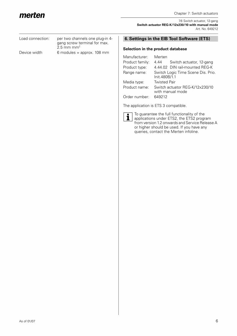
Selection in the product database
The application is ETS 3 compatible.
| To guarantee the full functionality of the applications under ETS2, the ETS2 program from version 1.2 onwards and Service Release A or higher should be used. If you have any queries, contact the Merten infoline.
Load connection: per two channels one plug-in 4-gang screw terminal for max. 2.5 mm mm2
Device width 6 modules = approx. 108 mm
6. Settings in the EIB Tool Software (ETS)
Manufacturer: MertenProduct family: 4.44 Switch actuator, 12-gangProduct type: 4.44.02 DIN rail-mounted REG-KRange name: Switch Logic Time Scene Dis. Prio.
Init.480B/1.1Media type: Twisted PairProduct name: Switch actuator REG-K/12x230/10
with manual modeOrder number: 649212

As of 01/07 7
Chapter 7: Switch actuators
7.6 Switch actuator, 12-gang Switch actuator REG-K/12x230/10 with manual mode
Switch Logic Time Scene Dis. Prio. Init. 4820/1.1 Art. No. 649212
Introduction
● General information
This software application enables you to program switch actuators using manual mode (referred to below as actuator), which switch loads via separate, floating make contacts.You can also operate the actuator using the push-buttons on the front. For more information see the section "Operation".All the settings described refer to ETS version 3, but you can use all the settings and functions with ETS version 2 as well.Maximum number of group addresses: 254Associations: 255
½ Caution!If you switch back to the preset values in either ETS 2 or ETS 3 (by clicking "Standard"), then all the values that you have changed so far will be deleted!
| Note: Due to the fact that various functions depend on other functions, these dependant functions are only visible and selectable in the ETS when the preceding function has been enabled. If you de-select functions or parameters, group addresses that have already been connected may be removed.
| Note: The application files (vd2 and vd3) are configured in such a way that the application loading time is considerably reduced. When you convert an ETS 2 project to ETS 3, you lose this time saving. It therefore makes sense to load the vd3 file when using ETS 3.
7. Application overview
Application Vers. Functions
Switch Link Delay Scene Block Priority Init.4820/1.1
1 Switching settings:Outputs switch in the make contact or break contact relay modesCentral functionTime functions (on/off delay, staircase lighting function)Scene function for switch outputsHigher-level functions (logic operation function, priority control)Disable function for switch outputsDevice functions:
Manual operation on the device with disable function for manual operation optionsStatus responseOperating display
7.1 Switch Logic Time Scene Dis. Prio. Init. 4820/1.1

As of 01/07 8
Chapter 7: Switch actuators
7.6 Switch actuator, 12-gang Switch actuator REG-K/12x230/10 with manual mode
Switch Logic Time Scene Dis. Prio. Init. 4820/1.1 Art. No. 649212
● Application functions
The software application for the actuator provides you with numerous functions. The description of the functions specifies and explains the parameters that are relevant for these functions. You will find an overview of all the parameters of the ETS application for the actuator in the last section "Parameters and settings“. The description is divided into:
Switching settings
Basic functionThese functions allow you to commission the device and equip it with simple functionality.– Switching outputs
Advanced functions– Central function– Time function (on/off delay, staircase lighting
function)– Scene function
Higher-level functionsHigher-level functions are executed before the basic function and advanced functions:– Logic operation function or priority control– Disable function
Device functions
In this chapter you will find explanations about:– Status messages– Manual operation and status displays– Behaviour after failure and recovery of supply
voltage– Behaviour after application download
Parameters and settings
– Overview of all parameters of the application
Switching settings
To switch electronic loads on and off, you can set the output channels of the actuator to the "Switching" operating mode. You can select the operating mode for each channel in the "Channel config" tab:
The descriptions below relate only to the settings for "Channel 1" and "Channel 2", but they are representative of all channels. If you select the operating mode "Switch" for two output channels, these output contacts are enabled. To enable you to control these two outputs, the "Switch object - channel 1" and "Switch object - channel 2" communication objects (1 bit) appear. You can use the "Channel 1" and "Channel 2" tabs to perform individual settings for each channel.
● Basic function:Switching outputs
You can specify the relay characteristic (make contact or break contact) for each output channel in the "Relay operation" parameter:
Output contacts 1 and 2 are controlled using the "Switching object - channel 1" and "Switching object - channel 2" communication objects. Telegram values have different effects, depending on the relay operating mode set:
"Make contact" relay operation
If the "Switching object" receives a telegram with the value "0", the contact is opened.If a telegram value of "1" is received, the contact is closed.Term definition:The setting values "activated" and "not activated" are used for the different switching states of the output contacts when the parameters are set. In "Make contact" relay operation, the following relationship exists:– activated = contact closed– not activated= contact open
Tab Parameter
Channel config Channel 1 and channel 2 operating modeChannel 3 and channel 4 operating modeChannel
Tab Parameter
Channel 1Channel 2
Relay operation

As of 01/07 9
Chapter 7: Switch actuators
7.6 Switch actuator, 12-gang Switch actuator REG-K/12x230/10 with manual mode
Switch Logic Time Scene Dis. Prio. Init. 4820/1.1 Art. No. 649212
"Break contact" relay operation
If the "Switching object" receives a telegram with the value "0", the contact is closed. If a telegram value of "1" is received, the contact is opened.Term definition:The setting values "activated" and "not activated" are used for the different switching states of the output contacts when the parameters are set. In "Break contact" relay operation, the following relationship exists:– activated = contact open– not activated = contact closed
Set the following parameters for this function in the ETS:
Communication objects
The switching commands for the output relay are received via the "Switch object" communication object:
● Advanced functions:Central function
You can use the central function to switch or dim several output channels simultaneously with a telegram command. This function is useful, for example, when you wish to switch off all lights at the touch of a button before going to bed in the evening, or when you leave your apartment.
Enabling the central function
In order to be able to use the central function for the individual switching channels, you first have to enable the function for the device once:
Tab Parameter
Channel 1Channel 2
Relay operation
Function Object name Type Prio Flags Behaviour
Channel 1Channel 2
Switch object 1 bit Low WC Receive
Telegram value
Output channel
"not activated"
"activated"
Telegram value
Output channel
"not activated"
"activated"
Tab Parameter
General Central function, general
Bus+ -
ON
Prog.
Hand RUN
Office
Office
CellarCorridorToiletKitchen
Kitchen
Toilet
Corridor
Cellar
Central switching
station
Bus+ -
ON
Prog.
Hand RUN
Office
Office
CellarCorridorToiletKitchen
Kitchen
Toilet
Corridor
Cellar
Central switching
station
As of 01/07 10
Chapter 7: Switch actuators
7.6 Switch actuator, 12-gang Switch actuator REG-K/12x230/10 with manual mode
Switch Logic Time Scene Dis. Prio. Init. 4820/1.1 Art. No. 649212
After the function has been enabled, the "Central object" communication object appears, which can now be used to receive the central control telegrams.Now you can activate the central function for each switching channel individually:
After the "Central function" parameter has been enabled, an output is switched on and off by the "Central object" when a telegram is received.
Priority
The central function has the same priority as the normal switching function. When a new object value is received via the "Central object", the effect is the same as when a new object value is received for the "Switching object" of the channel. Accordingly, all the assigned channel functions (e.g. time functions, logic operation function) are also executed.
Parameter settings in the ETS
Communication objects
The central control telegrams can be received via the "Central object" communication object:
● Advanced functions:Time functions
The software application provides different functions which enable you to switch the connected loads dependant on time. These are:– ON delay– OFF delay– Staircase lighting function
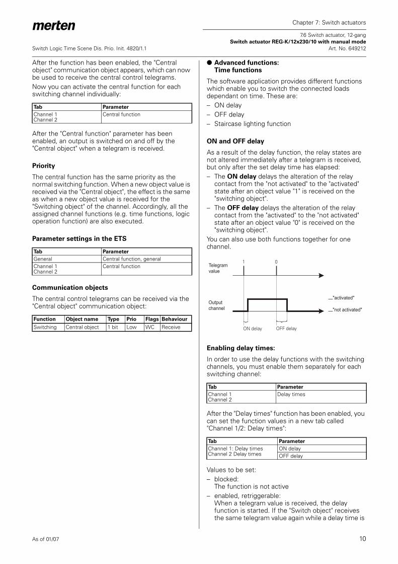
ON and OFF delay
As a result of the delay function, the relay states are not altered immediately after a telegram is received, but only after the set delay time has elapsed:– The ON delay delays the alteration of the relay
contact from the "not activated" to the "activated" state after an object value "1" is received on the "switching object".
– The OFF delay delays the alteration of the relay contact from the "activated" to the "not activated" state after an object value "0" is received on the "switching object".
You can also use both functions together for one channel.
Enabling delay times:
In order to use the delay functions with the switching channels, you must enable them separately for each switching channel:
After the "Delay times" function has been enabled, you can set the function values in a new tab called "Channel 1/2: Delay times":
Values to be set:– blocked:
The function is not active– enabled, retriggerable:
When a telegram value is received, the delay function is started. If the "Switch object" receives the same telegram value again while a delay time is
Tab Parameter
Channel 1Channel 2
Central function
Tab Parameter
General Central function, generalChannel 1Channel 2
Central function
Function Object name Type Prio Flags Behaviour
Switching Central object 1 bit Low WC Receive
Tab Parameter
Channel 1Channel 2
Delay times
Tab Parameter
Channel 1: Delay timesChannel 2 Delay times
ON delayOFF delay
ON delay OFF delay
1 0Telegram value
Output channel "not activated"
"activated"

As of 01/07 11
Chapter 7: Switch actuators
7.6 Switch actuator, 12-gang Switch actuator REG-K/12x230/10 with manual mode
Switch Logic Time Scene Dis. Prio. Init. 4820/1.1 Art. No. 649212
running, the delay time is re-started from the beginning.
– enabled, not retriggerable:When a telegram value is first received, the delay function is started. After the delay time has elapsed, the delay relay is switched, regardless of whether further telegrams with the same value have been received during the delay time.
The active time delays are each calculated by multiplying their setting values for the time basis x factor. Accordingly, with the standard values, a value of 1 s x 3 = 3 s, results, with a value of 1 s x 120 = 120 s for the OFF delay.
Interrupting the delay function
If a delay function has been started when a new object value is received, and if the output channel receives a telegram with the opposite object value while the delay time is running, the delay function is interrupted. The relay is not switched:– When the object value "0" is received, any ON delay
that is running is interrupted.
– When the object value "1" is received, any OFF delay that is running is interrupted.
Delay functions and staircase lighting function
The combination of an ON delay with the staircase lighting function results in the delayed start of the staircase lighting function.The way in which the staircase lighting function is combined with an OFF delay depends on how you have defined the staircase lighting function:– With the staircase lighting function with manual
OFF option ("with manual OFF"), the OFF delay is started on the "Switch object" when a manual OFF telegram is received. The output is switched off once the OFF delay has expired (not activated).
– With the staircase lighting function without manual OFF option ("without manual OFF"), the receipt of a manual OFF telegram has no effect on the "Switch object". The staircase lighting function runs through to the end and switches the output relay directly into the "not activated" state. An OFF delay cannot be set.
Parameter settings in the ETS
Set the following parameters for the delay function in the ETS:
Tab Parameter
Channel 1: Delay timesChannel 2 Delay times
Time base for ON delayFactor for ON delay (1-255)Time base for OFF delayFactor for OFF delay (1-255)
1 1 0 0Telegram value
Output channel "not activated"
"activated"
1 1 0 0Telegram value
Output channel "not activated"
"activated"
Tab Parameter
Channel 1Channel 2
Delay time
Channel 1: Delay timesChannel 2 Delay times
ON delayTime base for ON delayFactor for ON delay (1-255)OFF delayTime base for OFF delayFactor for OFF delay (1-255)
1 0 1 0 1 0Telegram value
Output channel "not activated"
"activated"

As of 01/07 12
Chapter 7: Switch actuators
7.6 Switch actuator, 12-gang Switch actuator REG-K/12x230/10 with manual mode
Switch Logic Time Scene Dis. Prio. Init. 4820/1.1 Art. No. 649212
Staircase lighting function
As well as the switching delays, the staircase lighting function also provides a third time function for the switch outputs. As the name already suggests, this function is used to switch on a load, such as the light in a staircase, via a bus telegram, and then to switch it back off after an adjustable period of time has elapsed. Switching off therefore requires no manually or automatically generated bus telegram. The actuator conducts the OFF procedure independently.
Enabling the staircase lighting function
In order to use the staircase lighting function with the switching channels, you must enable it separately for each switching channel:
After the staircase lighting function has been enabled, you can set the function values in a new tab called "Channel 1/2: Staircase lighting function":
Manually interrupting the staircase lighting function
If the "Switch object" receives a new telegram with the object value "0" while a staircase timer is running, the reaction of the switching channel will depend on your setting for the "staircase timer function" parameter:– with manual OFF: After the object value "0" is
received, the output is switched to the "not activated" position. In this case, an active OFF delay
delays the transfer of the relay states from "activated" to "not activated".
– without manual OFF: A telegram with the object value "0" has no effect. The staircase timer set continues to run normally until the end. An OFF delay cannot be set.
Restarting the staircase lighting function
If the "Switch object" receives a new telegram with the object value "1" while a staircase timer is running, the reaction of the switching channel will depend on your setting for the "staircase timer" parameter:– not retriggerable: A new telegram received with the
object value "1" has no effect. The function continues to run normally.
Tab Parameter
Channel 1Channel 2
Staircase lighting function
Tab Parameter
Channel 1: Staircase lighting functionChannel 2 Staircase lighting function
Staircase lighting functionStaircase timerTime base, staircase timerFactor for staircase timer (1-255)Pre-warning at the end of the staircase timePre-warning time (1-255), factor x 1 s
1
Staircase timer
Telegram value
Output channel "not activated"
"activated"
1 0
Staircase timer
Telegram value
Output channel "not activated"
"activated"
1 0
Staircase timer
Telegram value
Output channel "not activated"
"activated"
1 1
Staircase timer
Telegram value
Output channel "not activated"
"activated"

As of 01/07 13
Chapter 7: Switch actuators
7.6 Switch actuator, 12-gang Switch actuator REG-K/12x230/10 with manual mode
Switch Logic Time Scene Dis. Prio. Init. 4820/1.1 Art. No. 649212
– retriggerable: After a new telegram has been received with the object value "1", the staircase timer is restarted.
Setting the staircase timer
If the "Switch object" receives a new telegram with the object value "1" when a staircase timer function is active, the output relay of the switching channel is switched to the "activated" position. After the set staircase lighting time has expired, the actuator automatically switches the output relay to the "not activated" position without a new telegram.The length of the staircase lighting time is calculated by multiplying your set values for the "Time basis for staircase lighting time" parameter x "Staircase lighting time factor (1-255)". A running time of 3 minutes (1 min x 3 = 3 mins.) results with the standard values.
Warning given before switching off
With the warning time before switching off, the user can be informed that the function is due to end soon when the lighting system switches off briefly. The user can restart (retrigger) the staircase lighting function with a push-button action. If they do nothing the function will continue to run normally.You can use the "Pre-warning at end of staircase lighting time" parameter to disable or release the OFF pre-warning. If the OFF pre-warning has been enabled, you can specify whether one, two or three pre-warning impulses should be given. The first pre-warning begins according to the set pre-warning time prior to the normal expiry of the current staircase lighting time. For each pre-warning, the output contact for the fixed time frame of 500 ms is switched to the "not activated" state. If you have activated more than one pre-warning, a wait time of 5 seconds is maintained between the pre-warning impulses.If a running staircase lighting function is interrupted by a manual OFF function, no pre-warning is given.
Parameter settings in the ETS
Set the following parameters for the staircase lighting function in the ETS:
1 1
Staircase timer
Telegram value
Output channel "not activated"
"activated"
Tab Parameter
Channel 1Channel 2
Staircase lighting function
Channel 1: Staircase lighting functionChannel 2 Staircase lighting function
Staircase lighting functionStaircase timerTime base, staircase timerFactor for staircase timer (1-255)Pre-warning at the end of the staircase timePre-warning time (1-255), factor x 1 s
As of 01/07 14
Chapter 7: Switch actuators
7.6 Switch actuator, 12-gang Switch actuator REG-K/12x230/10 with manual mode
Switch Logic Time Scene Dis. Prio. Init. 4820/1.1 Art. No. 649212
● Advanced functions: Scene function
The scene function can be used when room functions for different utilities (e.g. lighting, heating, roller shutters) need to be changed simultaneously with a push-button action or an operating command. Retrieving a scene allows you, for example, to switch or dim the room lighting to a desired value, move the blinds into a desired position and turn the slats, switch heating control to daytime operation and switch on the power supply to the socket-outlets in a room. The telegrams of these functions may not have only different formats, but also values with a different meaning (e.g. "0" for lighting OFF and blinds OPEN). Without the scene functions, you need to send a separate telegram to each actuator in order to achieve the same setting.The scene function allows you to integrate the channels into scene control. There are up to five different scenes for each output channel. Each of these scenes can be assigned one of 64 possible scene addresses (which correspond to telegram values 0 to 63). You can enter the relay states (activated or not activated) for the output channels as scene values.When the actuator receives a telegram with the retrieval of a scene address, the output relay is switched to the stored setting. The scene values that you save on commissioning can be replaced later by users if they wish to make an alteration.
Telegram format
Telegrams for the scene function have the following data format: L X D D D D D D.– L = learning bit– X = is not used– DDDDDD = scene address retrievedIf the learn bit in a telegram has the value "0", the relay states stored for this scene address are retrieved and set.If the learn bit has the value "1", then the current output states are saved as new scene values for the scene address.Examples:– Telegram value 57
Binary 0011 1101Hexadecimal 39Retrieve scene address 57
– Telegram value 29Binary 0001 1101Hexadecimal 1DRetrieve scene address 29
– Telegram value 157Binary 1001 1101Hexadecimal 9DLearn scene address 29
– Telegram value 141Binary 10001101Hexadecimal 8DLearn scene address 13
Activating the scene function
In order to be able to use the scene function for the individual switching channels, you first have to enable the function for the device once:
After you enable the function, the communication object "Scene object" appears. This object is now able to receive the scene telegrams.Now you can activate the function for each switching channel individually:
After you enable the "Scenes" parameter, the "Channel 1: Scenes" or "Channel 2: Scenes" tab appears, in which you can specify the switching state of the output relay when a scene is retrieved. You can activate each of the five scenes independently of each other.
Retrieving and storing scenes
The "Scene object" object allows you to retrieve scene values for the output relay. After a scene telegram is received, the actuator evaluates the transmitted scene address and switches the outputs to the stored scene values.If the "Scene object" receives a scene telegram with learn bit "1", then the current relay state is saved as the new scene value in all those scenes allocated the scene number received.
| Note: If a scene address is assigned to several scenes within a channel, only the scene first found with this scene address is retrieved or stored. You can avoid this by issuing different scene addresses within a channel.
Example - State after downloading:– Channel 1
Scene 1 active with scene address 10 with relay state OFFScene 2 active with scene address 20 with relay state ON
– Channel 2Scene 3 active with scene address 20 with relay state ON
Tab Parameter
General Scenes general
Tab Parameter
Channel 1Channel 2
Scenes
As of 01/07 15
Chapter 7: Switch actuators
7.6 Switch actuator, 12-gang Switch actuator REG-K/12x230/10 with manual mode
Switch Logic Time Scene Dis. Prio. Init. 4820/1.1 Art. No. 649212
– Scene object receives "Retrieve scene address 20" telegramChannel 1 switches ONChannel 2 switches ON
– Scene object receives "Retrieve scene address 10" telegramChannel 1 switches OFFChannel 2 remains ON
– Switch object channel 2 receives "OFF" telegramChannel 1 remains OFFChannel 2 switches OFF
– Scene object receives "Learn scene address 20" telegram
– Scene object receives "Retrieve scene address 20" telegramChannel 1 does not react, because the relay state is already "OFF"Channel 2 does not react, because the relay state is already "OFF"
If you enabled the parameter "Replace scene values in the actuator on download", then the scene values saved in the device are replaced with your default values on download. If you don't want to replace the values in the device, then you must disable this parameter. In this case, only those scene values for which the parameters were set during the first download are written into the device memory. If an application is then downloaded, the scene values will remain in the device memory.
Parameter settings in the ETS
Set the following parameters for the scene function in the ETS:
Priority
The scene function has the same priority as the normal switching function via the "Switch object". This should be taken into account with regard to the priority of the higher-level functions.
Communication objects
The scene telegrams can be received via the "Scene object" communication object:
Tab Parameter
General Scenes generalChannel 1Channel 2
Scenes
Channel 1: ScenesChannel 2 Scenes
Replace scene values in the actuator on downloadScene 1Scene 1 scene address (0-63)Scene 1 relay stateScene 2Scene 2 scene address (0-63)Scene 2 relay stateScene 3Scene 3 scene address (0-63)Scene 3 relay stateScene 4Scene 4 scene address (0-63)Scene 4 relay stateScene 5Scene 5 scene address (0-63)Scene 5 relay state
Function Object name Type Prio Flags Behaviour
Scenes Scene object 8 bit Low WC Receive

As of 01/07 16
Chapter 7: Switch actuators
7.6 Switch actuator, 12-gang Switch actuator REG-K/12x230/10 with manual mode
Switch Logic Time Scene Dis. Prio. Init. 4820/1.1 Art. No. 649212
● Higher-level functions
Higher-level functions (blocking, logic operation, priority control) have a higher priority than the basic functions (switching) and the advanced functions (central function, time functions, scene function).The priority sequence is as follows:1. Disable function2. Logic operation / priority control3. Switching, central function, time function, scenes
You can enable the "Disable function" via:
For the disable function, the parameter card "Channel 1/2: Disable function" appears.
A parameter enables you to activate one of the two higher-level functions, "Logic operation" or "Priority control" for each switching channel:
Depending on which higher-level functions you select, new parameter cards appear in which you can complete the additional function settings.For the logic function, the parameter card "Channel 1/2: Logic operation" appears. To set the priority control function, the new parameter card "Channel 1/2: priority control" appears.
● Higher-level function:logic operation
If you activate the logic operation function, a new object is available called the "logic object". The value of the logic object is logically operated with the current value of the switch object. The state of the output relay is determined by the logic result, if no disable function with a higher priority is active.
The logical functions AND, OR and XOR are possible as logic operations:
The output relay is switched to the "activated" or "not activated" state, depending on the logical result.
* a running staircase lighting timer function corresponds to object value 1
Example:
A permanent ON or permanent OFF function can be realised, for example, using the logic operation function:– Permanent ON function: OR logic operation and
logic object = "1"The output is always activated, regardless of the operation on site. If the logic object receives the value "0", the output can be operated normally again on site.
– Permanent OFF function: AND logic operation and logic object = "0" The output remains permanently not activated until the logic object receives the value "1". Only then can the output also be switched on site. In this way, the light in a school classroom can be enabled and blocked using a timer switch, for example.
| A logic operation is only effective if no disable function with a higher priority is active.
Tab Parameter
Channel 1Channel 2
Disable function
Tab Parameter
Channel 1Channel 2
Priority function
Tab Parameter
Channel 1: Logic operationChannel 2 Logic operation
Type of logic operation
Switch object channel 1
Logic object channel 1
Type of logic operation
Switching state, output relay channel 1
Logic operation type = AND
object Switch object*
object logic operation
Relay status
0 0 not actuated0 1 not actuated1 0 not actuated1 1 actuated
Logic operation type = OR
object Switch object*
object logic operation
Relay status
0 0 not actuated0 1 actuated1 0 actuated1 1 actuated
Logic operation type = XOR
object Switch object*
object logic operation
Relay status
0 0 not actuated0 1 actuated1 0 actuated1 1 not actuated
As of 01/07 17
Chapter 7: Switch actuators
7.6 Switch actuator, 12-gang Switch actuator REG-K/12x230/10 with manual mode
Switch Logic Time Scene Dis. Prio. Init. 4820/1.1 Art. No. 649212
Logic operation function following bus voltage recovery and downloading
The initial value of the logic object after a bus voltage recovery and downloading is applied at the logic operation function input.After the bus voltage recovery, the logic object can adopt the following values:– „0“– „1“The relay is directly switched in the specified direction via the logic operation function and the object values, if no disable function is active.
After downloading, the logic operation function is also reinstated after a bus voltage recovery. The "Relay state after downloading" parameter in the "Channel 1/2: Failure behaviour" tab determines whether the relay is switched or not in this case.If the "Relay state after downloading" parameter is set to "No reaction", the logic operation function is activated as described, although the relay is not switched.If the "Relay state after downloading" parameter is set to "As for bus voltage recovery", the logic operation function is activated as described, and the relay is switched accordingly.
You will find further information on this subject in the chapter "Operating behaviour on failure and recovery of supply voltage".
Parameter settings in the ETS
Set the following parameters for this function in the ETS:
Communication objects
The logic operation telegrams can be received via the "Logic operation object" communication object:
● Higher-level functions:Priority control
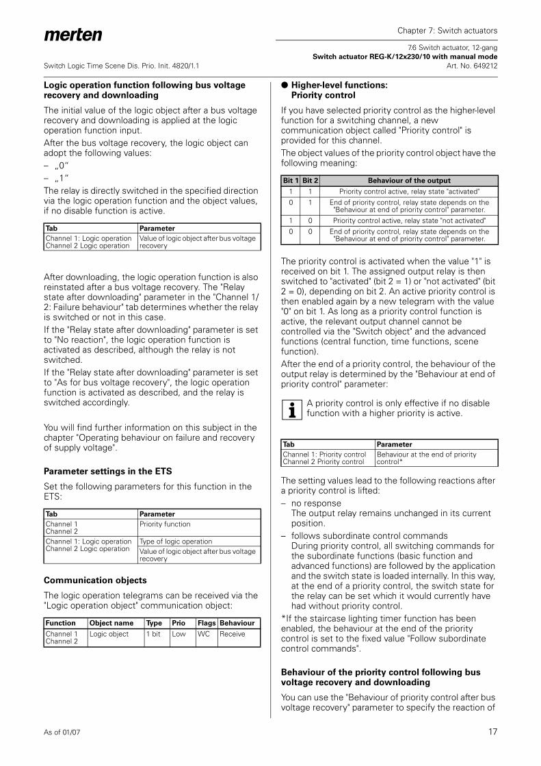
If you have selected priority control as the higher-level function for a switching channel, a new communication object called "Priority control" is provided for this channel.The object values of the priority control object have the following meaning:
The priority control is activated when the value "1" is received on bit 1. The assigned output relay is then switched to "activated" (bit 2 = 1) or "not activated" (bit 2 = 0), depending on bit 2. An active priority control is then enabled again by a new telegram with the value "0" on bit 1. As long as a priority control function is active, the relevant output channel cannot be controlled via the "Switch object" and the advanced functions (central function, time functions, scene function). After the end of a priority control, the behaviour of the output relay is determined by the "Behaviour at end of priority control" parameter:
| A priority control is only effective if no disable function with a higher priority is active.
The setting values lead to the following reactions after a priority control is lifted:– no response
The output relay remains unchanged in its current position.
– follows subordinate control commandsDuring priority control, all switching commands for the subordinate functions (basic function and advanced functions) are followed by the application and the switch state is loaded internally. In this way, at the end of a priority control, the switch state for the relay can be set which it would currently have had without priority control.
*If the staircase lighting timer function has been enabled, the behaviour at the end of the priority control is set to the fixed value "Follow subordinate control commands".
Behaviour of the priority control following bus voltage recovery and downloading
You can use the "Behaviour of priority control after bus voltage recovery" parameter to specify the reaction of
Tab Parameter
Channel 1: Logic operationChannel 2 Logic operation
Value of logic object after bus voltage recovery
Tab Parameter
Channel 1Channel 2
Priority function
Channel 1: Logic operationChannel 2 Logic operation
Type of logic operationValue of logic object after bus voltage recovery
Function Object name Type Prio Flags Behaviour
Channel 1Channel 2
Logic object 1 bit Low WC Receive
Bit 1 Bit 2 Behaviour of the output
1 1 Priority control active, relay state "activated"0 1 End of priority control, relay state depends on the
"Behaviour at end of priority control" parameter.1 0 Priority control active, relay state "not activated"0 0 End of priority control, relay state depends on the
"Behaviour at end of priority control" parameter.
Tab Parameter
Channel 1: Priority controlChannel 2 Priority control
Behaviour at the end of priority control*
As of 01/07 18
Chapter 7: Switch actuators
7.6 Switch actuator, 12-gang Switch actuator REG-K/12x230/10 with manual mode
Switch Logic Time Scene Dis. Prio. Init. 4820/1.1 Art. No. 649212
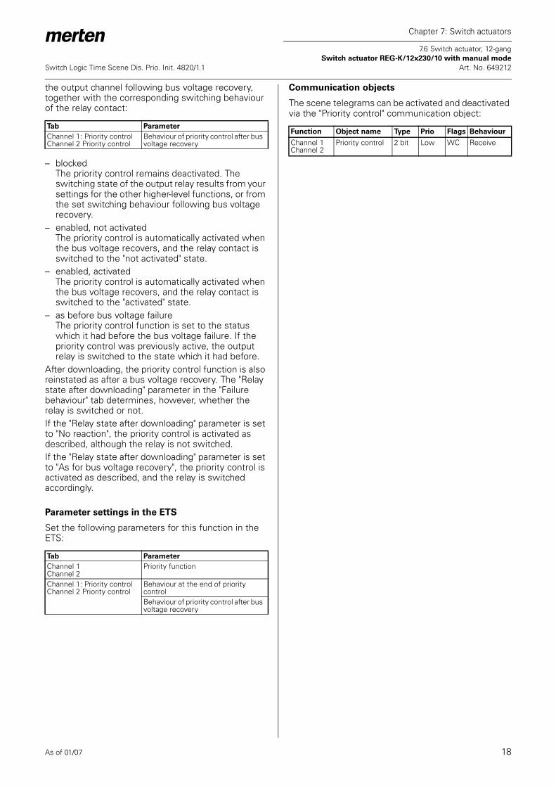
the output channel following bus voltage recovery, together with the corresponding switching behaviour of the relay contact:
– blockedThe priority control remains deactivated. The switching state of the output relay results from your settings for the other higher-level functions, or from the set switching behaviour following bus voltage recovery.
– enabled, not activatedThe priority control is automatically activated when the bus voltage recovers, and the relay contact is switched to the "not activated" state.
– enabled, activatedThe priority control is automatically activated when the bus voltage recovers, and the relay contact is switched to the "activated" state.
– as before bus voltage failureThe priority control function is set to the status which it had before the bus voltage failure. If the priority control was previously active, the output relay is switched to the state which it had before.
After downloading, the priority control function is also reinstated as after a bus voltage recovery. The "Relay state after downloading" parameter in the "Failure behaviour" tab determines, however, whether the relay is switched or not.If the "Relay state after downloading" parameter is set to "No reaction", the priority control is activated as described, although the relay is not switched.If the "Relay state after downloading" parameter is set to "As for bus voltage recovery", the priority control is activated as described, and the relay is switched accordingly.
Parameter settings in the ETS
Set the following parameters for this function in the ETS:
Communication objects
The scene telegrams can be activated and deactivated via the "Priority control" communication object:
Tab Parameter
Channel 1: Priority controlChannel 2 Priority control
Behaviour of priority control after bus voltage recovery
Tab Parameter
Channel 1Channel 2
Priority function
Channel 1: Priority controlChannel 2 Priority control
Behaviour at the end of priority controlBehaviour of priority control after bus voltage recovery
Function Object name Type Prio Flags Behaviour
Channel 1Channel 2
Priority control 2 bit Low WC Receive

As of 01/07 19
Chapter 7: Switch actuators
7.6 Switch actuator, 12-gang Switch actuator REG-K/12x230/10 with manual mode
Switch Logic Time Scene Dis. Prio. Init. 4820/1.1 Art. No. 649212
● Higher-level function:Disable function
You can use the disable function to systematically activate/not activate an output channel, and to disable it in this position. The state of the output channel cannot be changed by other control commands as long as the block is active. You can activate the disable function for each switching channel individually:
After the disable function is released, a new communication object called "Disable object" is provided for the switching channel, together with a new parameter card called "Channel 1/2: Disable function". You can use "Disable object" to activate and deactivate a channel block.First choose the object value at which the output should be blocked:
If the "Disable object" receives a telegram with the object value which you have specified for the "Block" parameter, then all other channel functions are blocked. You can define the reaction of the output relay via the "Behaviour at start of block" parameter:
The set values lead to the following reactions:– no reaction
The output relay remains unchanged in its current position.
– actuatedThe output relay switches to the "activated" state.
– not actuatedThe output relay switches to the "not activated" state.
If the disable object receives a telegram with the opposite object value to the activation, the block is removed and the output relay takes on the state which you have specified in the "Behaviour at end of block" parameter:
The set values lead to the following reactions:– no reaction
The output relay remains unchanged in its current position.
– follows subordinate control commandsDuring the disable function, all switching commands for the subordinate functions are followed by the application and the switch state is
loaded internally. In this way, at the end of the block, the switch state for the relay can be set which it would currently have had without the block.
If one of the higher-level functions, logic operation or priority control is active after the block has ended, the "Behaviour after the block has ended" parameter is ineffective. The state of the output relay is immediately controlled by the active function.*If the staircase lighting timer function has been enabled, the behaviour at the end of the disable function is set to the fixed value "Follow subordinate control commands".
Disable function following bus voltage recovery and downloading
The "Behaviour of the block following bus voltage recovery" parameter allows you to specify how you want the disable function to respond after the bus voltage returns:
Values to be set:– inactive
After bus voltage has been recovered, the disable function is deactivated, regardless of its status prior to bus voltage failure.
– activeAfter a bus voltage recovery, the disable function is activated and the output is switched back into the state which you have specified in the "Behaviour at the start of block" parameter. If you have set the "no reaction" value here, the output is blocked in its current state.
– as before bus voltage failure The disable function is switched to the state which was active before the bus voltage failure. If the disable function was active, the output is controlled by its settings in the "Behaviour at start of block" parameter.
After downloading, the disable function is also set as it was after a bus voltage recovery. The "Relay state after downloading" parameter in the parameter card "Channel 1/2: Failure behaviour" determines whether the relay is switched or not in this case.If the "Relay state after downloading" parameter is set to "No reaction", the block is activated as was previously set, but the output relay is not switched.If the "Relay state after downloading" parameter is set to the value "As for bus voltage recovery", the disable function is activated as previously specified, and the relay is switched accordingly.
Tab Parameter
Channel 1Channel 2
Disable function
Tab Parameter
Channel 1: Disable functionChannel 2 Disable function
Block
Tab Parameter
Channel 1: Disable functionChannel 2 Disable function
Behaviour at start of block
Tab Parameter
Channel 1: Disable functionChannel 2 Disable function
Behaviour at end of block*
Tab Parameter
Channel 1: Disable functionChannel 2 Disable function
Behaviour of the block after bus voltage recovery

As of 01/07 20
Chapter 7: Switch actuators
7.6 Switch actuator, 12-gang Switch actuator REG-K/12x230/10 with manual mode
Switch Logic Time Scene Dis. Prio. Init. 4820/1.1 Art. No. 649212
Parameter settings in the ETS
Set the following parameters for the disable function in the ETS:
Communication objects
The disable function can be activated and deactivated via the "Disable object" communication object:
Device functions
● Status messages/status feedback
The software application provides you with options to report the current device status and the status of output channels via communication objects. Depending on these status messages, you can trigger certain control processes or enable and disable functions in the system.In addition, status messages are also suitable for displaying current operating statuses by means of visualisation software.The status messages of the output channels are made available through communication objects. You can set the transmission characteristics of these status objects to one of the following values using parameters:– blocked
The status object is not active.– active status feedback object
After a change is made, the new values are automatically transmitted (position height, angle of rotation of the slat, relay closed or open)
– passive status objectThe status object does not transmit its values. However, the current status is available and can be read out by other bus devices.
Transmission behaviour of the status messages in time
You can prioritise the interval between two status telegrams for the device. This setting applies for the transmission behaviour of all status messages.
If there is only one pending transmission job, then the signal is sent immediately. If there are several status messages pending, then the first one is sent immediately and the remainder are staggered according to the delay time specified in the "Minimum interval between status messages" parameter.
Tab Parameter
Channel 1Channel 2
Disable function
Channel 1: Disable functionChannel 2 Disable function
BlockBehaviour at start of blockBehaviour at end of blockBehaviour of the block after bus voltage recovery
Function Object name Type Prio Flags Behaviour
Channel 1Channel 2
Disable object 1 bit Low WC Receive
Tab Parameter
General Minimum interval between status messages
Status messages
Telegrams
Minimum distance
S1 S2 S3 S4 S5 S6 S7
S1 S2 S3 S4 S5 S6 S7
As of 01/07 21
Chapter 7: Switch actuators
7.6 Switch actuator, 12-gang Switch actuator REG-K/12x230/10 with manual mode
Switch Logic Time Scene Dis. Prio. Init. 4820/1.1 Art. No. 649212
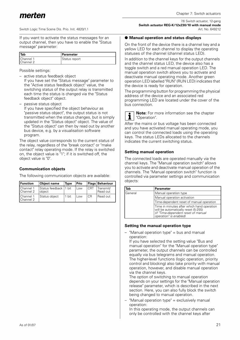
If you want to activate the status messages for an output channel, then you have to enable the "Status message" parameter:
Possible settings:– active status feedback object
If you have set the "Status message" parameter to the "Active status feedback object" value, the switching status of the output relay is transmitted each time the status is changed via the "Status feedback object" object.
– passive status objectIf you have specified the object behaviour as "passive status object", the output status is not transmitted when the status changes, but is simply updated in the "Status object" object. The value of the "Status object" can then by read out by another bus device, e.g. by a visualisation software program.
The object value corresponds to the current status of the relay, regardless of the "break contact" or "make contact" relay operating mode. If the relay is switched on, the object value is "1"; if it is switched off, the object value is "0".
Communication objects
The following communication objects are available:
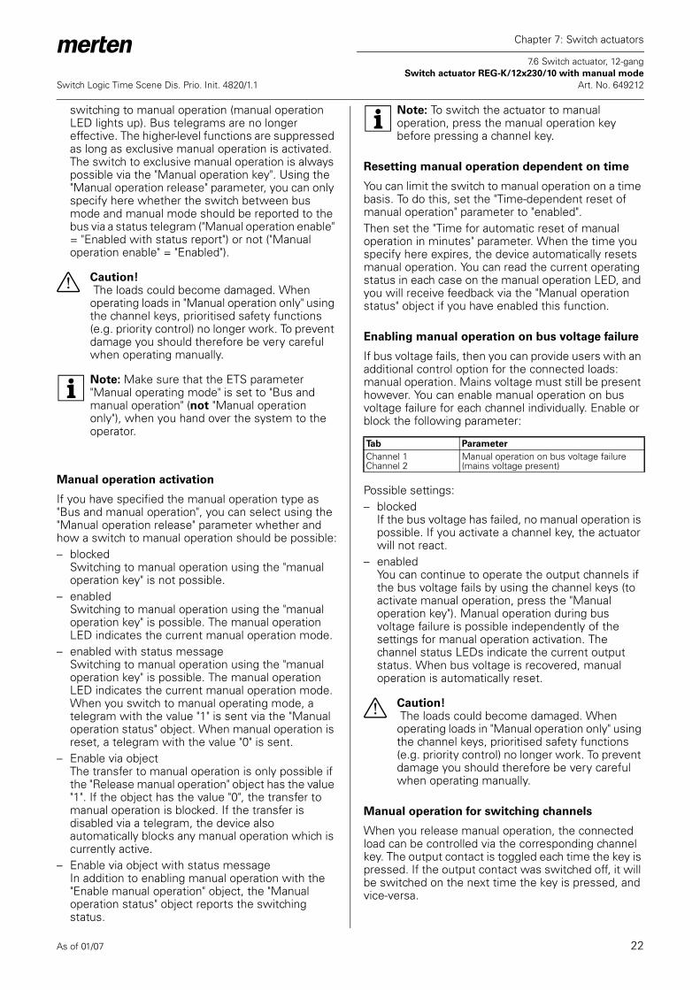
● Manual operation and status displays
On the front of the device there is a channel key and a yellow LED for each channel to display the operating statuses of the channel (channel status LED).In addition to the channel keys for the output channels and the channel status LED, the device also has a toggle switch and a red manual operation LED. The manual operation switch allows you to activate and deactivate manual operating mode. Another green operation LED labelled "RUN" (RUN LED) indicates that the device is ready for operation.The programming button for programming the physical address of the device and an associated red programming LED are located under the cover of the bus connection.
| Note: For more information see the chapter "Operation".
After the mains or bus voltage has been connected and you have activated manual operating mode, you can control the connected loads using the operating keys. The status LEDs allocated to the channels indicates the current switching status.
Setting manual operation
The connected loads are operated manually via the channel keys. The "Manual operation switch" allows you to activate and deactivate manual operation of the channels. The "Manual operation switch" function is controlled via parameter settings and communication objects:
Setting the manual operation type
– "Manual operation type" = bus and manual operation:If you have selected the setting value "Bus and manual operation" for the "Manual operation type" parameter, the output channels can be controlled equally via bus telegrams and manual operation. The higher-level functions (logic operation, priority control and blocking) also take priority with manual operation, however, and disable manual operation via the channel keys.The option of switching to manual operation depends on your settings for the "Manual operation release" parameter, which is described in the next section. Here, you can also fully block the switch being changed to manual operation.
– "Manual operation type" = exclusively manual operation:In this operating mode, the output channels can only be controlled with the channel keys after
Tab Parameter
Channel 1Channel 2
Status report
Function Object name Type Prio Flags Behaviour
Channel 1Channel 2
Status feedback object
1 bit Low CRT Transmit/Read out
Channel 1Channel 2
Status object 1 bit Low CR Read out
Tab Parameter
General Manual operation typeManual operation activationTime-dependent reset of manual operationTime in minutes after which hand operation will be automatically reset (5-255)(if "Time-dependent reset of manual operation" is enabled)
As of 01/07 22
Chapter 7: Switch actuators
7.6 Switch actuator, 12-gang Switch actuator REG-K/12x230/10 with manual mode
Switch Logic Time Scene Dis. Prio. Init. 4820/1.1 Art. No. 649212
switching to manual operation (manual operation LED lights up). Bus telegrams are no longer effective. The higher-level functions are suppressed as long as exclusive manual operation is activated.The switch to exclusive manual operation is always possible via the "Manual operation key". Using the "Manual operation release" parameter, you can only specify here whether the switch between bus mode and manual mode should be reported to the bus via a status telegram ("Manual operation enable" = "Enabled with status report") or not ("Manual operation enable" = "Enabled").
½ Caution! The loads could become damaged. When operating loads in "Manual operation only" using the channel keys, prioritised safety functions (e.g. priority control) no longer work. To prevent damage you should therefore be very careful when operating manually.
| Note: Make sure that the ETS parameter "Manual operating mode" is set to "Bus and manual operation" (not "Manual operation only"), when you hand over the system to the operator.
Manual operation activation
If you have specified the manual operation type as "Bus and manual operation", you can select using the "Manual operation release" parameter whether and how a switch to manual operation should be possible:– blocked
Switching to manual operation using the "manual operation key" is not possible.
– enabledSwitching to manual operation using the "manual operation key" is possible. The manual operation LED indicates the current manual operation mode.
– enabled with status messageSwitching to manual operation using the "manual operation key" is possible. The manual operation LED indicates the current manual operation mode. When you switch to manual operating mode, a telegram with the value "1" is sent via the "Manual operation status" object. When manual operation is reset, a telegram with the value "0" is sent.
– Enable via objectThe transfer to manual operation is only possible if the "Release manual operation" object has the value "1". If the object has the value "0", the transfer to manual operation is blocked. If the transfer is disabled via a telegram, the device also automatically blocks any manual operation which is currently active.
– Enable via object with status messageIn addition to enabling manual operation with the "Enable manual operation" object, the "Manual operation status" object reports the switching status.
| Note: To switch the actuator to manual operation, press the manual operation key before pressing a channel key.
Resetting manual operation dependent on time
You can limit the switch to manual operation on a time basis. To do this, set the "Time-dependent reset of manual operation" parameter to "enabled".Then set the "Time for automatic reset of manual operation in minutes" parameter. When the time you specify here expires, the device automatically resets manual operation. You can read the current operating status in each case on the manual operation LED, and you will receive feedback via the "Manual operation status" object if you have enabled this function.
Enabling manual operation on bus voltage failure
If bus voltage fails, then you can provide users with an additional control option for the connected loads: manual operation. Mains voltage must still be present however. You can enable manual operation on bus voltage failure for each channel individually. Enable or block the following parameter:
Possible settings: – blocked
If the bus voltage has failed, no manual operation is possible. If you activate a channel key, the actuator will not react.
– enabledYou can continue to operate the output channels if the bus voltage fails by using the channel keys (to activate manual operation, press the "Manual operation key"). Manual operation during bus voltage failure is possible independently of the settings for manual operation activation. The channel status LEDs indicate the current output status. When bus voltage is recovered, manual operation is automatically reset.
½ Caution! The loads could become damaged. When operating loads in "Manual operation only" using the channel keys, prioritised safety functions (e.g. priority control) no longer work. To prevent damage you should therefore be very careful when operating manually.
Manual operation for switching channels
When you release manual operation, the connected load can be controlled via the corresponding channel key. The output contact is toggled each time the key is pressed. If the output contact was switched off, it will be switched on the next time the key is pressed, and vice-versa.
Tab Parameter
Channel 1Channel 2
Manual operation on bus voltage failure (mains voltage present)
As of 01/07 23
Chapter 7: Switch actuators
7.6 Switch actuator, 12-gang Switch actuator REG-K/12x230/10 with manual mode
Switch Logic Time Scene Dis. Prio. Init. 4820/1.1 Art. No. 649212
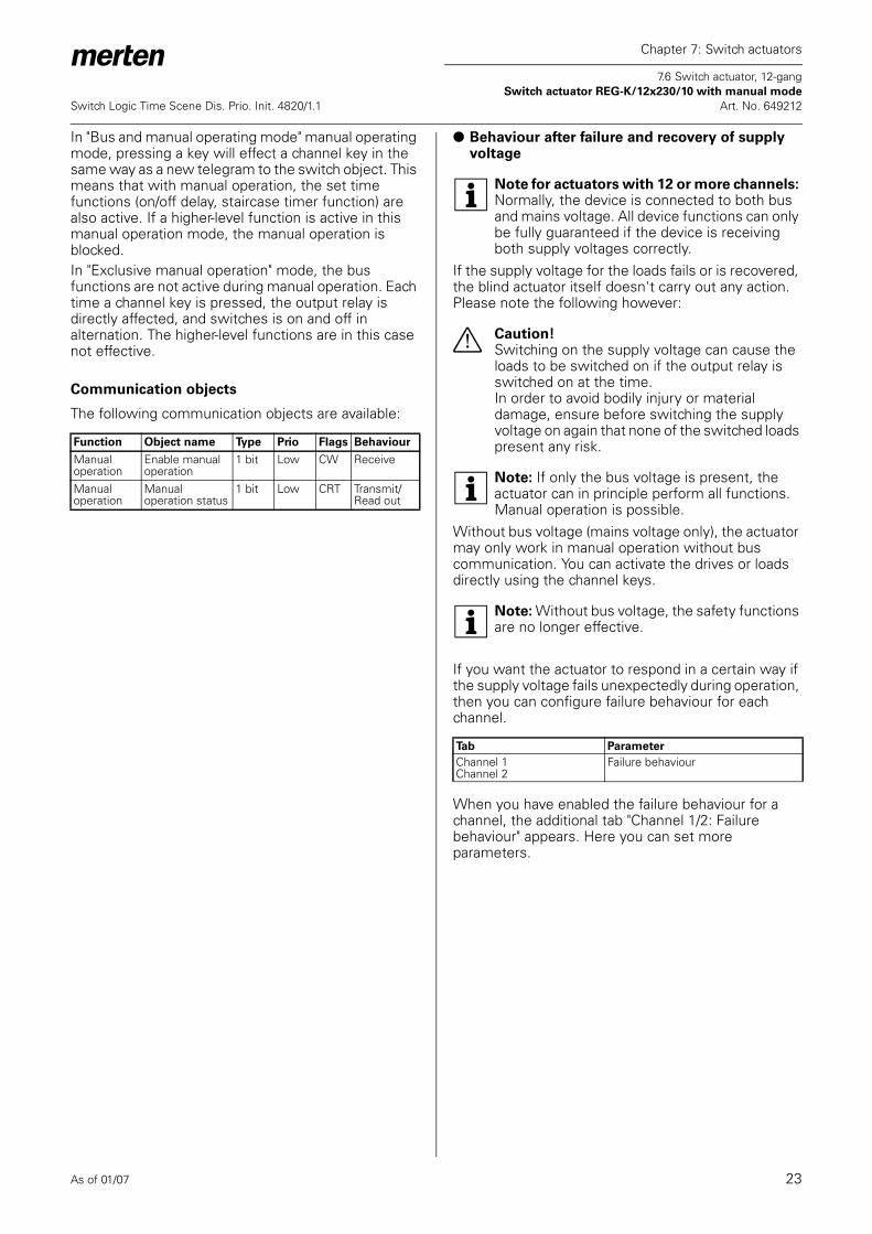
In "Bus and manual operating mode" manual operating mode, pressing a key will effect a channel key in the same way as a new telegram to the switch object. This means that with manual operation, the set time functions (on/off delay, staircase timer function) are also active. If a higher-level function is active in this manual operation mode, the manual operation is blocked.In "Exclusive manual operation" mode, the bus functions are not active during manual operation. Each time a channel key is pressed, the output relay is directly affected, and switches is on and off in alternation. The higher-level functions are in this case not effective.
Communication objects
The following communication objects are available:
● Behaviour after failure and recovery of supply voltage
| Note for actuators with 12 or more channels: Normally, the device is connected to both bus and mains voltage. All device functions can only be fully guaranteed if the device is receiving both supply voltages correctly.
If the supply voltage for the loads fails or is recovered, the blind actuator itself doesn't carry out any action. Please note the following however:
½ Caution!Switching on the supply voltage can cause the loads to be switched on if the output relay is switched on at the time. In order to avoid bodily injury or material damage, ensure before switching the supply voltage on again that none of the switched loads present any risk.
| Note: If only the bus voltage is present, the actuator can in principle perform all functions. Manual operation is possible.
Without bus voltage (mains voltage only), the actuator may only work in manual operation without bus communication. You can activate the drives or loads directly using the channel keys.
| Note: Without bus voltage, the safety functions are no longer effective.
If you want the actuator to respond in a certain way if the supply voltage fails unexpectedly during operation, then you can configure failure behaviour for each channel.
When you have enabled the failure behaviour for a channel, the additional tab "Channel 1/2: Failure behaviour" appears. Here you can set more parameters.
Function Object name Type Prio Flags Behaviour
Manual operation
Enable manual operation
1 bit Low CW Receive
Manual operation
Manual operation status
1 bit Low CRT Transmit/Read out
Tab Parameter
Channel 1Channel 2
Failure behaviour
As of 01/07 24
Chapter 7: Switch actuators
7.6 Switch actuator, 12-gang Switch actuator REG-K/12x230/10 with manual mode
Switch Logic Time Scene Dis. Prio. Init. 4820/1.1 Art. No. 649212
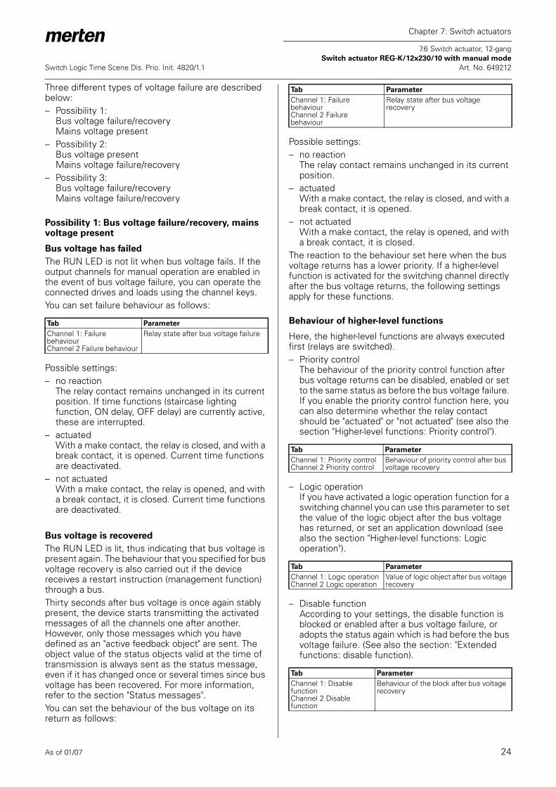
Three different types of voltage failure are described below:– Possibility 1:
Bus voltage failure/recoveryMains voltage present
– Possibility 2:Bus voltage presentMains voltage failure/recovery
– Possibility 3:Bus voltage failure/recoveryMains voltage failure/recovery
Possibility 1: Bus voltage failure/recovery, mains voltage present
Bus voltage has failed
The RUN LED is not lit when bus voltage fails. If the output channels for manual operation are enabled in the event of bus voltage failure, you can operate the connected drives and loads using the channel keys.You can set failure behaviour as follows:
Possible settings:– no reaction
The relay contact remains unchanged in its current position. If time functions (staircase lighting function, ON delay, OFF delay) are currently active, these are interrupted.
– actuated With a make contact, the relay is closed, and with a break contact, it is opened. Current time functions are deactivated.
– not actuatedWith a make contact, the relay is opened, and with a break contact, it is closed. Current time functions are deactivated.
Bus voltage is recovered
The RUN LED is lit, thus indicating that bus voltage is present again. The behaviour that you specified for bus voltage recovery is also carried out if the device receives a restart instruction (management function) through a bus.Thirty seconds after bus voltage is once again stably present, the device starts transmitting the activated messages of all the channels one after another. However, only those messages which you have defined as an "active feedback object" are sent. The object value of the status objects valid at the time of transmission is always sent as the status message, even if it has changed once or several times since bus voltage has been recovered. For more information, refer to the section "Status messages".You can set the behaviour of the bus voltage on its return as follows:
Possible settings:– no reaction
The relay contact remains unchanged in its current position.
– actuated With a make contact, the relay is closed, and with a break contact, it is opened.
– not actuatedWith a make contact, the relay is opened, and with a break contact, it is closed.
The reaction to the behaviour set here when the bus voltage returns has a lower priority. If a higher-level function is activated for the switching channel directly after the bus voltage returns, the following settings apply for these functions.
Behaviour of higher-level functions
Here, the higher-level functions are always executed first (relays are switched).– Priority control
The behaviour of the priority control function after bus voltage returns can be disabled, enabled or set to the same status as before the bus voltage failure. If you enable the priority control function here, you can also determine whether the relay contact should be "actuated" or "not actuated" (see also the section "Higher-level functions: Priority control").
– Logic operationIf you have activated a logic operation function for a switching channel you can use this parameter to set the value of the logic object after the bus voltage has returned, or set an application download (see also the section "Higher-level functions: Logic operation").
– Disable functionAccording to your settings, the disable function is blocked or enabled after a bus voltage failure, or adopts the status again which is had before the bus voltage failure. (See also the section: "Extended functions: disable function).
Tab Parameter
Channel 1: Failure behaviourChannel 2 Failure behaviour
Relay state after bus voltage failure
Tab Parameter
Channel 1: Failure behaviourChannel 2 Failure behaviour
Relay state after bus voltage recovery
Tab Parameter
Channel 1: Priority controlChannel 2 Priority control
Behaviour of priority control after bus voltage recovery
Tab Parameter
Channel 1: Logic operationChannel 2 Logic operation
Value of logic object after bus voltage recovery
Tab Parameter
Channel 1: Disable functionChannel 2 Disable function
Behaviour of the block after bus voltage recovery
As of 01/07 25
Chapter 7: Switch actuators
7.6 Switch actuator, 12-gang Switch actuator REG-K/12x230/10 with manual mode
Switch Logic Time Scene Dis. Prio. Init. 4820/1.1 Art. No. 649212
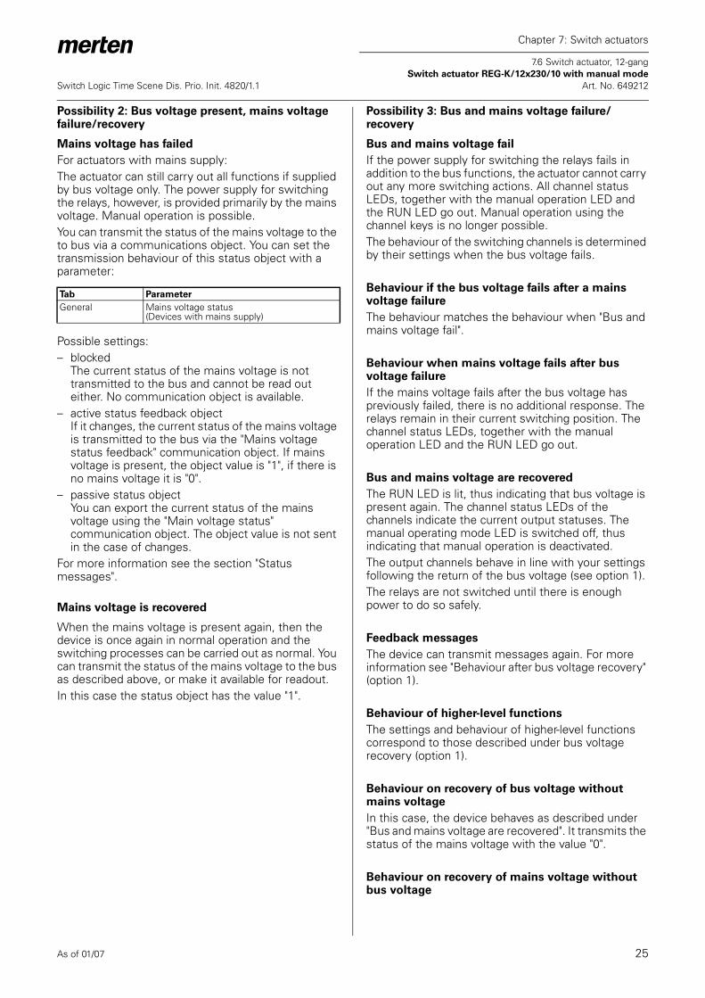
Possibility 2: Bus voltage present, mains voltage failure/recovery
Mains voltage has failed
For actuators with mains supply: The actuator can still carry out all functions if supplied by bus voltage only. The power supply for switching the relays, however, is provided primarily by the mains voltage. Manual operation is possible.You can transmit the status of the mains voltage to the to bus via a communications object. You can set the transmission behaviour of this status object with a parameter:
Possible settings:– blocked
The current status of the mains voltage is not transmitted to the bus and cannot be read out either. No communication object is available.
– active status feedback objectIf it changes, the current status of the mains voltage is transmitted to the bus via the "Mains voltage status feedback" communication object. If mains voltage is present, the object value is "1", if there is no mains voltage it is "0".
– passive status objectYou can export the current status of the mains voltage using the "Main voltage status" communication object. The object value is not sent in the case of changes.
For more information see the section "Status messages".
Mains voltage is recovered
When the mains voltage is present again, then the device is once again in normal operation and the switching processes can be carried out as normal. You can transmit the status of the mains voltage to the bus as described above, or make it available for readout.In this case the status object has the value "1".
Possibility 3: Bus and mains voltage failure/recovery
Bus and mains voltage fail
If the power supply for switching the relays fails in addition to the bus functions, the actuator cannot carry out any more switching actions. All channel status LEDs, together with the manual operation LED and the RUN LED go out. Manual operation using the channel keys is no longer possible.The behaviour of the switching channels is determined by their settings when the bus voltage fails.
Behaviour if the bus voltage fails after a mains voltage failure
The behaviour matches the behaviour when "Bus and mains voltage fail".
Behaviour when mains voltage fails after bus voltage failure
If the mains voltage fails after the bus voltage has previously failed, there is no additional response. The relays remain in their current switching position. The channel status LEDs, together with the manual operation LED and the RUN LED go out.
Bus and mains voltage are recovered
The RUN LED is lit, thus indicating that bus voltage is present again. The channel status LEDs of the channels indicate the current output statuses. The manual operating mode LED is switched off, thus indicating that manual operation is deactivated. The output channels behave in line with your settings following the return of the bus voltage (see option 1).The relays are not switched until there is enough power to do so safely.
Feedback messages
The device can transmit messages again. For more information see "Behaviour after bus voltage recovery" (option 1).
Behaviour of higher-level functions
The settings and behaviour of higher-level functions correspond to those described under bus voltage recovery (option 1).
Behaviour on recovery of bus voltage without mains voltage
In this case, the device behaves as described under "Bus and mains voltage are recovered". It transmits the status of the mains voltage with the value "0".
Behaviour on recovery of mains voltage without bus voltage
Tab Parameter
General Mains voltage status(Devices with mains supply)

As of 01/07 26
Chapter 7: Switch actuators
7.6 Switch actuator, 12-gang Switch actuator REG-K/12x230/10 with manual mode
Switch Logic Time Scene Dis. Prio. Init. 4820/1.1 Art. No. 649212
If mains voltage is recovered without bus voltage, the device behaves as described under bus voltage failure with mains voltage present (option 1).
Communication objects
The following communication objects are available:
● Behaviour after application download
Before the first download after commissioning, all relays are switched off (default setting). Manual operation is deactivated; the manual operation LED is switched off.You can specify the download behaviour of the output channels:
Possible settings:– no response
After a download, the relays remain in their current status. The status of active, higher-level functions is set again. This does not result in the relays being switched.
– as for bus voltage recoveryThe relays behave in line with your settings for a return of bus voltage for this channel. If a higher-level function (logic operation, priority control or lock) is active, the behaviour is executed which you have specified for these functions.
If an internal error or a defective download results in a status in which the application is no longer operational, the device does not respond. The output relays remain in their last position. All LEDs are switched off.
Function Object name Type Prio Flags Behaviour
Status Mains voltage status feedback
1 bit Low KÜL Transmit
Status Mains voltage status
1 bit Low CR Transmit/Read out
Tab Parameter
Channel 1Channel 2
Failure behaviour
Channel 1: Failure behaviourChannel 2 Failure behaviour
Relay status after download

As of 01/07 27
Chapter 7: Switch actuators
7.6 Switch actuator, 12-gang Switch actuator REG-K/12x230/10 with manual mode
Switch Logic Time Scene Dis. Prio. Init. 4820/1.1 Art. No. 649212
Parameters and settings
This section lists all the parameters of the ETS application with their settings and default settings.
If "Channel X and channel Y operating mode" in "Channel config" tab = switching:
General
Parameter Setting
Manual operation type Bus and manual operation
Manual operation onlyManual operation activation(if "Manual operation type" = bus and manual operation)
blockedenabled
enabled with status message=> "Manual operation status" objectEnable via object=> "Manual operation enable" objectEnable via object with status message=> "Manual operation status" object=> "Manual operation enable" object
Manual operation activation(if "Manual operation type" = exclusively manual operation)
enabled
enabled with status message=> "Manual operation status" object
Time-dependent reset of manual operation(if "Enable manual operation" is enabled)
blocked
enabled
Time for automatic reset of manual operation mode in minutes (5-255) (if "time-dependent reset of manual operation mode" enabled)
60, 5 to 255
Scenes general blocked
enabled=> "Scene object" object
Mains voltage status(Devices with mains supply)
blocked
active status feedback object=> "Mains voltage feedback" objectpassive status object=> "Mains voltage status" object
Minimum interval between status messages
100 ms, 200 ms, 500 ms, 1 s, 1.5 s, 2 s
Central object blocked
enabled=> "Central object" object
Channel config
Parameter Setting
Channel 1 and channel 2 operating mode
blockedSwitching
Channel 3 and channel 4 operating mode
blocked
SwitchingChannel 5 and channel 6 operating mode
blocked
SwitchingChannel 7 and channel 8 operating mode
blocked
SwitchingChannel 9 and channel 10 operating mode
blocked
SwitchingChannel 11 and channel 12 operating mode
blocked
SwitchingSwitching=> Tab "Channel X"=> Tab "Channel Y"=> Object "Switch object" channel X=> Object "Switch object" channel Y
Channel XChannel Y
Parameter Setting
Relay operation make contact
break contactStaircase lighting function blocked
enabled=> Tab "Channel X/Y" Staircase lighting function"
Delay times blocked
enabled=> Tab "Channel X/Y" Delay times"
Scenes blocked
enabled=> Tab "Channel X/Y" Scenes"
Central function blocked
enabledPriority function blocked
Logic operation=> Tab "Channel X/Y: Logic operation"=> Object "Logic object" (for channel X, Y)Priority control=> Tab "Channel X/Y" Priority control"=> Object "Priority control" (for channel X/Y)
Disable function blocked
Logic operation=> Tab "Channel X/Y: Disable function"=> Object "Disable object" (for channel X/Y)
Failure behaviour blocked
enabled=> Tab "Channel X/Y" Failure behaviour"
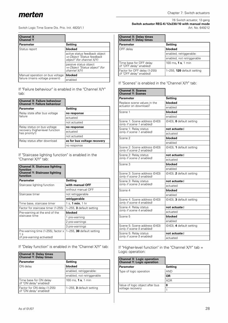
As of 01/07 28
Chapter 7: Switch actuators
7.6 Switch actuator, 12-gang Switch actuator REG-K/12x230/10 with manual mode
Switch Logic Time Scene Dis. Prio. Init. 4820/1.1 Art. No. 649212
If "Failure behaviour" is enabled in the "Channel X/Y" tab:
If "Staircase lighting function" is enabled in the "Channel X/Y" tab:
If "Delay function" is enabled in the "Channel X/Y" tab:
If "Scenes" is enabled in the "Channel X/Y" tab:
If "Higher-level function" in the "Channel X/Y" tab = Logic operation:
Status report blocked
active status feedback object=> Object "Status feedback object" (for channel X/Y)passive status object=> Object "Status object" (for channel X/Y)
Manual operation on bus voltage failure (mains voltage present)
blocked
enabled
Channel X: Failure behaviourChannel Y: Failure behaviour
Parameter Setting
Relay state after bus voltage failure
no response
actuatednot actuated
Relay status on bus voltage recovery (higher-level function has priority!)
no response
actuatednot actuated
Relay status after download as for bus voltage recovery
no response
Channel X: Staircase lighting functionChannel Y: Staircase lighting function
Parameter Setting
Staircase lighting function with manual OFF
without manual OFFStaircase timer not retriggerable
retriggerable
Time base, staircase timer 1 s, 1 min, 1 hrFactor for staircase timer (1-255) 1–255, 3 default settingPre-warning at the end of the staircase time
blocked
1 pre-warning2 pre-warnings3 pre-warnings
Pre-warning time (1-255), factor x 1 s(if pre-warning activated)
1–255, 30 default setting
Channel X: Delay timesChannel Y: Delay times
Parameter Setting
ON delay blocked
enabled, retriggerable:enabled, not retriggerable
Time base for ON delay(if "ON delay" enabled)
100 ms, 1 s, 1 min
Factor for ON delay (1-255) (if "ON delay" enabled)
1–255, 3 default setting
Channel XChannel Y
Parameter Setting
OFF delay blocked
enabled, retriggerable:enabled, not retriggerable
Time base for OFF delay(if "OFF delay" enabled)
100 ms, 1 s, 1 min
Factor for OFF delay (1-255) (if "OFF delay" enabled)
1–255, 120 default setting
Channel X: ScenesChannel Y: Scenes
Parameter Setting
Replace scene values in the actuator on download?
blocked
enabledScene 1 blocked
enabledScene 1: Scene address (0-63) (only if scene 1 enabled)
(0-63), 0 default setting
Scene 1: Relay status (only if scene 1 enabled)
not actuatedactuated
Scene 2 blocked
enabledScene 2: Scene address (0-63) (only if scene 2 enabled)
(0-63), 1 default setting
Scene 2: Relay status (only if scene 2 enabled)
not actuatedactuated
Scene 3 blocked
enabledScene 3: Scene address (0-63) (only if scene 3 enabled)
(0-63), 2 default setting
Scene 3: Relay status (only if scene 3 enabled)
not actuatedactuated
Scene 4 blocked
enabledScene 4: Scene address (0-63) (only if scene 4 enabled)
(0-63), 3 default setting
Scene 4: Relay status (only if scene 4 enabled)
not actuatedactuated
Scene 5 blocked
enabledScene 5: Scene address (0-63) (only if scene 5 enabled)
(0-63), 4 default setting
Scene 5: Relay status (only if scene 5 enabled)
not actuatedactuated
Channel X: Logic operationChannel Y: Logic operation
Parameter Setting
Type of logic operation ANDOR
XORValue of logic object after bus voltage recovery
0
1
Channel X: Delay timesChannel Y: Delay times
Parameter Setting

As of 01/07 29
Chapter 7: Switch actuators
7.6 Switch actuator, 12-gang Switch actuator REG-K/12x230/10 with manual mode
Switch Logic Time Scene Dis. Prio. Init. 4820/1.1 Art. No. 649212
If "Higher-level function" in the "Channel X/Y" tab = Priority control:
If "Disable function" is enabled in the "Channel X/Y" tab:
Channel X: Priority controlChannel Y: Priority control
Parameter Setting
Behaviour at the end of priority control(if "staircase lighting function" blocked)
no response
follows subordinate control commands
Behaviour at the end of priority control(if "staircase lighting function" enabled)
follows subordinate control commands
Behaviour of priority control after bus voltage recovery
blocked
enabled, not activatedenabled, activatedas before bus voltage failure
Channel X: Disable functionChannel Y: Disable function
Parameter Setting
Block for object value "0"for object value "1"
Behaviour at start of block no response
actuatednot actuated
Behaviour at end of block (higher-level function has priority!)(if "staircase lighting function" blocked)
no response
follows subordinate control commands
Behaviour at end of block(higher-level function has priority!)(if "staircase lighting function" enabled)
follows subordinate control commands
Behaviour of the block after bus voltage recovery
inactive
activeas before bus voltage failure