switch basics · 2-3, 5-4 connected 8-9, 11-10 connected 2-1, 5-4 connected 8-7, 11-10 connected....
TRANSCRIPT

Switch Basics

Basic Structure of a Switch

Electrical Circuit

Poles and Schematics
Single Pole Double Pole Three Pole Four Pole
Pole - Number of circuits the switch can control at one time
Footprint
Bottom View of Switch

Throw
Single Throw SwitchON-NONE-OFF
Double Throw SwitchON-NONE-ON
Throw - Number of electrical circuits within a pole
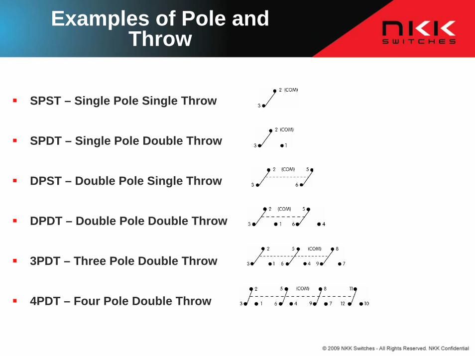
Examples of Pole and Throw
SPST – Single Pole Single Throw
SPDT – Single Pole Double Throw
DPST – Double Pole Single Throw
DPDT – Double Pole Double Throw
3PDT – Three Pole Double Throw
4PDT – Four Pole Double Throw
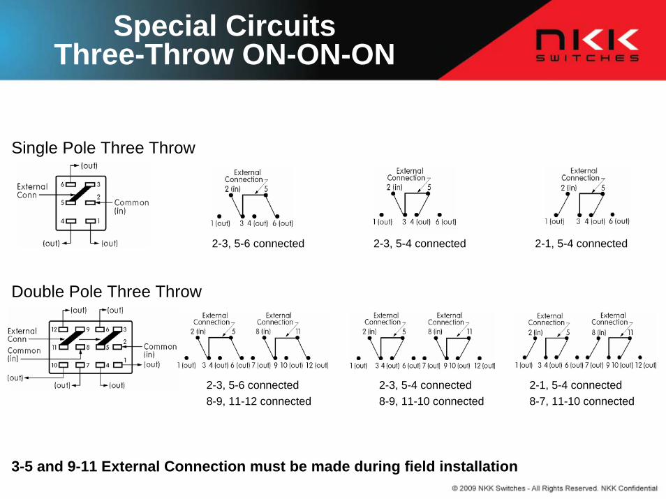
Special Circuits Three-Throw ON-ON-ON
3-5 and 9-11 External Connection must be made during field installation
Single Pole Three Throw
Double Pole Three Throw
2-3, 5-6 connected 2-1, 5-4 connected2-3, 5-4 connected
2-3, 5-6 connected8-9, 11-12 connected
2-3, 5-4 connected8-9, 11-10 connected
2-1, 5-4 connected8-7, 11-10 connected

Alternate and Momentary
Alternate with No Latchdown
Alternate with Latchdown
Momentary

N/O and N/C
N/O = Normally Open N/C = Normally Closed

Lever Position and Circuits
(ON) is momentaryNote: There is a distinction between “throw” and “position”. Among two position switches there are single throw ON-NONE-OFF and double throw ON-NONE-ON.
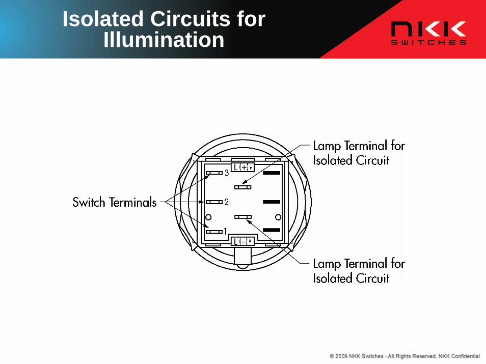
Isolated Circuits for Illumination

Types of Terminals
Solder Lug Straight PC Straight PC with Bracket
Right Angle PC Vertical PCWire-wrap
SMD SMD with Bracket
Solder Lug/ Quick Connect
Right Angle SMD with Bracket
Screw Lug Quick Connect Solder Lug
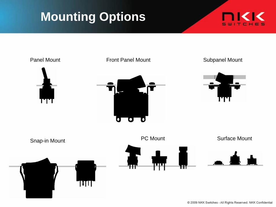
Mounting Options
Panel Mount Subpanel MountFront Panel Mount
Snap-in Mount Surface MountPC Mount

Type of Actuators
Toggles
Rockers
Standard Flat Locking Lever Cone Large Bat
Pushbuttons
Paddles
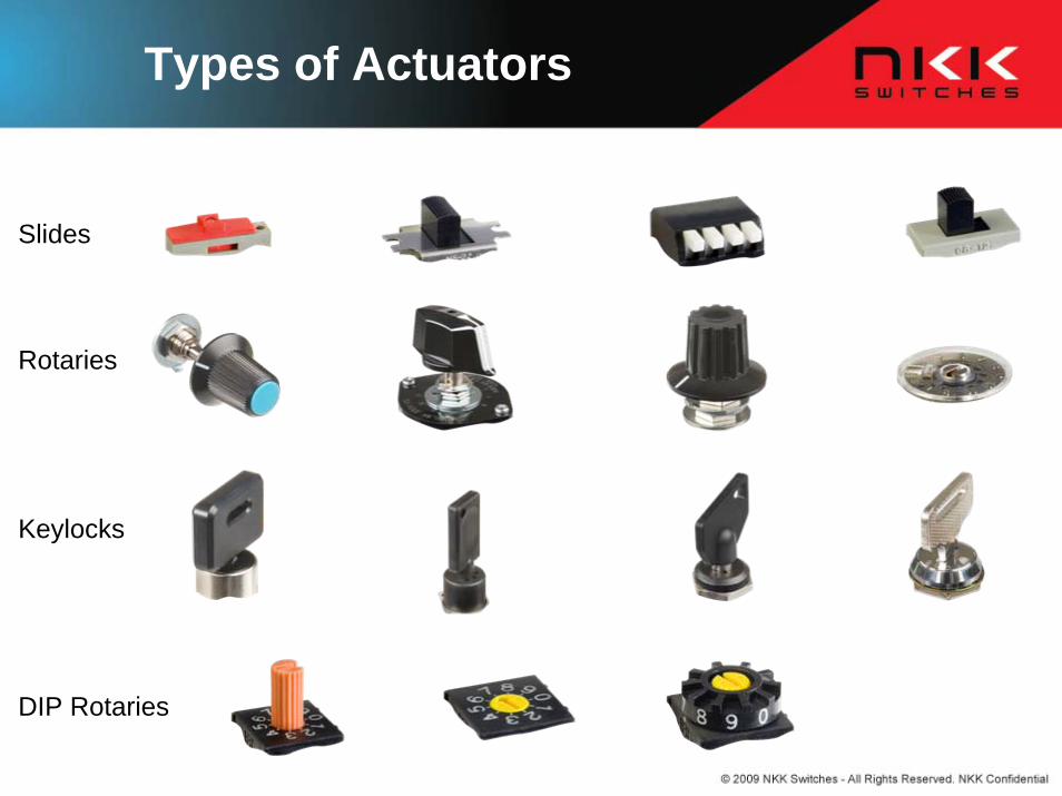
Types of Actuators
DIP Rotaries
Rotaries
Slides
Keylocks
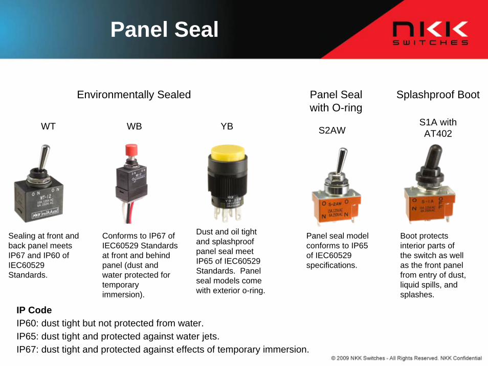
Panel Seal
Environmentally Sealed Splashproof BootPanel Seal with O-ring
Conforms to IP67 of IEC60529 Standards at front and behind panel (dust and water protected for temporary immersion).
Dust and oil tight and splashproofpanel seal meet IP65 of IEC60529 Standards. Panel seal models come with exterior o-ring.
Sealing at front and back panel meets IP67 and IP60 of IEC60529 Standards.
Panel seal model conforms to IP65 of IEC60529 specifications.
IP CodeIP60: dust tight but not protected from water.IP65: dust tight and protected against water jets.IP67: dust tight and protected against effects of temporary immersion.
Boot protects interior parts of the switch as well as the front panel from entry of dust, liquid spills, and splashes.
WT WB YB S2AWS1A with AT402
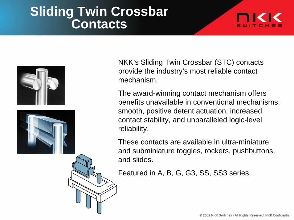
Sliding Twin Crossbar Contacts
NKK’s Sliding Twin Crossbar (STC) contacts provide the industry’s most reliable contact mechanism.
The award-winning contact mechanism offers benefits unavailable in conventional mechanisms: smooth, positive detent actuation, increased contact stability, and unparalleled logic-level reliability.
These contacts are available in ultra-miniature and subminiature toggles, rockers, pushbuttons, and slides.
Featured in A, B, G, G3, SS, SS3 series.
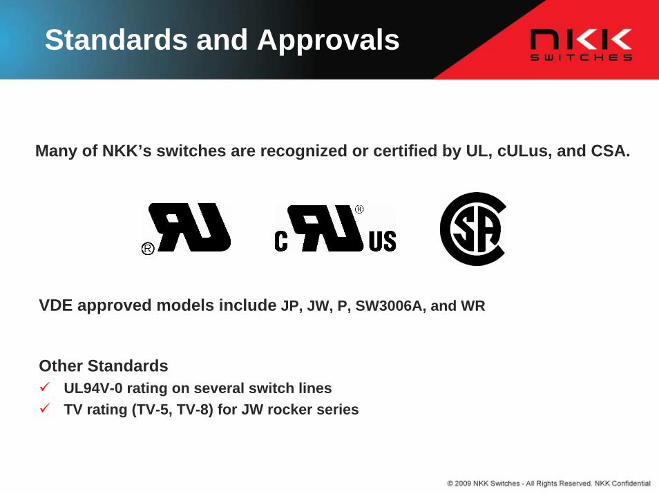
Standards and Approvals
Many of NKK’s switches are recognized or certified by UL, cULus, and CSA.
Other StandardsUL94V-0 rating on several switch linesTV rating (TV-5, TV-8) for JW rocker series
VDE approved models include JP, JW, P, SW3006A, and WR
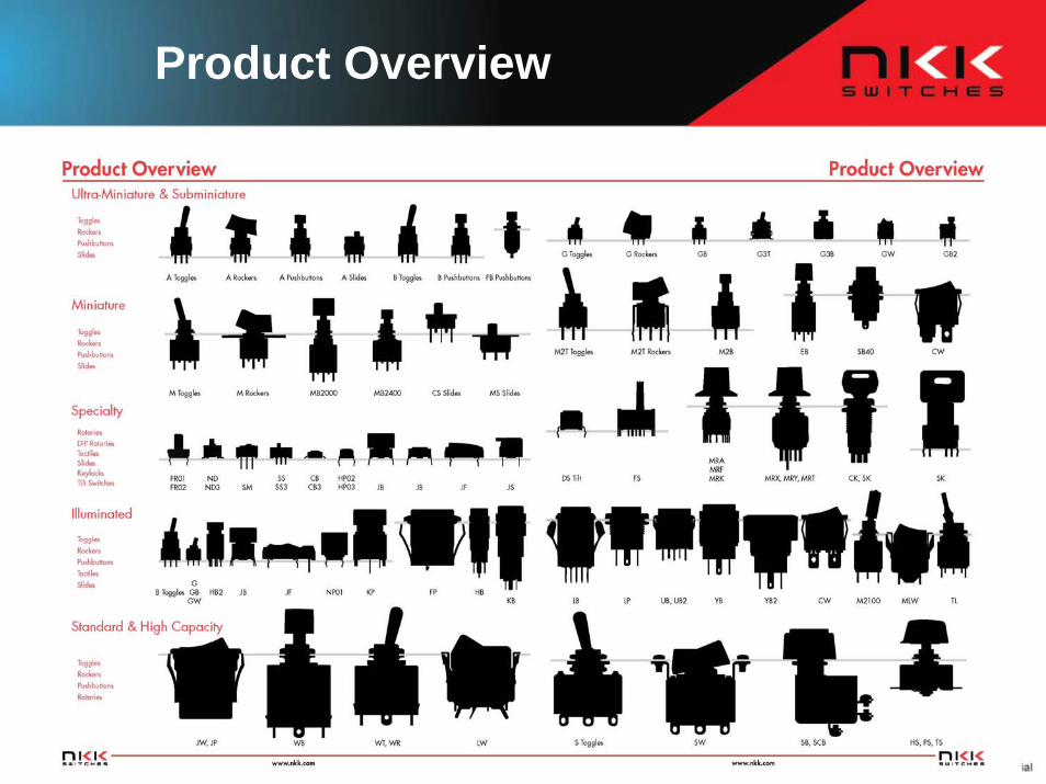
Product Overview