switchgear type simosec, up to 24 kv, air-insulated ... · switchgear type simosec, up to 24 kv,...
TRANSCRIPT
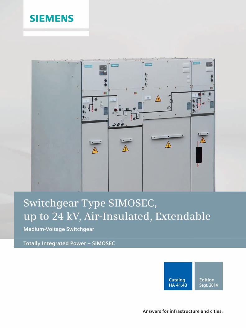
Totally Integrated Power – SIMOSEC
Switchgear Type SIMOSEC, up to 24 kV, Air-Insulated, ExtendableMedium-Voltage Switchgear
Edition Sept. 2014
Catalog HA 41.43
Answers for infrastructure and cities.
Neue Bilder von Jens Weibert
Gibt es ein chinesisches Beispiel?
R-H
A41
-05
5 e
ps
R-H
A4
0-1
11.t
if
R-H
A4
0-1
12.t
if
R-H
A41
-115
.tif
2 Switchgear Type SIMOSEC, up to 24 kV, Air-Insulated, Extendable · Siemens HA 41.43 · Sept. 2014
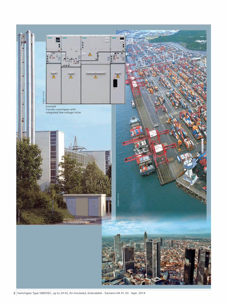
Example Transfer switchgear with integrated low-voltage niche
Utilities transfer substation for industrial plants
3Switchgear Type SIMOSEC, up to 24 kV, Air-Insulated, Extendable · Siemens HA 41.43 · Sept. 2014
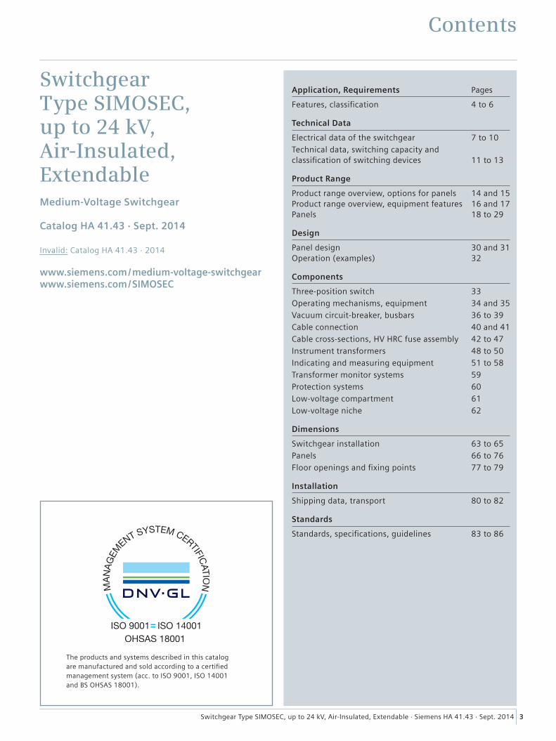
Contents
Application, Requirements Pages
Features, classification 4 to 6
Technical Data
Electrical data of the switchgear 7 to 10Technical data, switching capacity and classification of switching devices 11 to 13
Product Range
Product range overview, options for panels 14 and 15 Product range overview, equipment features 16 and 17 Panels 18 to 29
Design
Panel design 30 and 31 Operation (examples) 32
Components
Three-position switch 33Operating mechanisms, equipment 34 and 35Vacuum circuit-breaker, busbars 36 to 39Cable connection 40 and 41Cable cross-sections, HV HRC fuse assembly 42 to 47Instrument transformers 48 to 50Indicating and measuring equipment 51 to 58Transformer monitor systems 59Protection systems 60Low-voltage compartment 61Low-voltage niche 62
Dimensions
Switchgear installation 63 to 65Panels 66 to 76Floor openings and fixing points 77 to 79
Installation
Shipping data, transport 80 to 82
Standards
Standards, specifications, guidelines 83 to 86
Switchgear Type SIMOSEC, up to 24 kV, Air-Insulated, ExtendableMedium-Voltage Switchgear
Catalog HA 41.43 · Sept. 2014 Invalid: Catalog HA 41.43 · 2014
www.siemens.com/medium-voltage-switchgear www.siemens.com/SIMOSEC
The products and systems described in this catalogare manufactured and sold according to a certifiedmanagement system (acc. to ISO 9001, ISO 14001and BS OHSAS 18001).
4 Switchgear Type SIMOSEC, up to 24 kV, Air-Insulated, Extendable · Siemens HA 41.43 · Sept. 2014
Features
Application, Requirements
*) For standards, see page 83
SIMOSEC switchgear is a factory-assembled, type-tested, three-phase, metal-enclosed, indoor switchgear according to IEC 62271-200 *) and GB 3906 *) for single busbars.
Typical uses
SIMOSEC switchgear is used for power distribution in distri-bution systems with busbar currents up to 1250 A.
Modular space-saving design allows use in
• Substations, customer transfer substations, distribution substations and switching substations of power supply and public utilities
• Public buildings, such as high-rise buildings, railway stations, hospitals
• Industrial plants.
Typical applications
• Wind power stations• High-rise buildings• Airports• Underground railway stations• Sewage treatment plants• Port facilities• Traction power supply systems• Automobile industry• Petroleum industry• Chemical industry• Unit-type heating power stations• Textile, paper and food industries• Emergency power supply installations• Shopping centers and data centers.
Modular design
• Individual panels, for free combination and extension• Option: Low-voltage compartments can be supplied in
two overall heights• Circuit-breaker panels for various applications.
Reliability
• Type and routine-tested *)
• No cross insulation between phases• Standardized and manufactured using numerically
controlled machines• Quality management system according to
DIN EN ISO 9001• More than 100,000 switchgear components in operation
worldwide for many years.
Personal safety
• All switching operations can be performed with closed panel front
• Metal-enclosed LSC 2 panels• HV HRC fuses and cable sealing ends are only accessible
when the outgoing feeders are earthed• Logical mechanical interlocking• Capacitive voltage detecting system for verification of safe
isolation from supply• Earthing of outgoing feeders by means of make-proof
earthing switches• Partition class: PM (partition of metal).
Compact design
Thanks to the use of gas-insulated switching-device vessel compact dimensions are possible. Thus
• Existing switchgear rooms can be used effectively• New constructions cost little• Costly city-area space is saved.
Security of operation
• Components, e.g. operating mechanisms, three-position switches, vacuum circuit-breakers proven for years
• LSC 2 panels: – Panels with metallic partition (metal-clad) between busbar and switching device and between switching device and cable compartment (R, T, L)
– Panels with metallic partition between switching device and busbar compartment
• Metal-enclosed switching-device vessel with three-position switch, gas-insulated
– Welded sealed-for-life switching-device vessel – No cross insulation between phases – With welded-in rotary bushings for operation – Three-position switch-disconnector with gas-insulated switching functions
– Three-position disconnector, gas-insulated – Switching functions CLOSE-OPEN-EARTH
• Operating mechanisms of switching devices accessible outside the switching-device vessel
• Maintenance-free operating mechanism parts (IEC 62271-1/ VDE 0671-1 *) and GB 11022 *))
• Mechanical position indication integrated in mimic diagram
• Switchgear interlocking system with logical mechanical interlocks
• Partition class: PM (partition of metal).
Reavailability
• Three-position switch-disconnector with gas-insulated, maintenance-free quenching principle
• Metallic partition between busbar compartment, switch-ing devices and cable compartment
• Separate pressure relief for each compartment• Cable testing without the need to isolate the busbar• Mounting location of three-phase current transformer for
selective disconnection of circuit-breaker feeders.
5Switchgear Type SIMOSEC, up to 24 kV, Air-Insulated, Extendable · Siemens HA 41.43 · Sept. 2014
Features
Application, Requirements
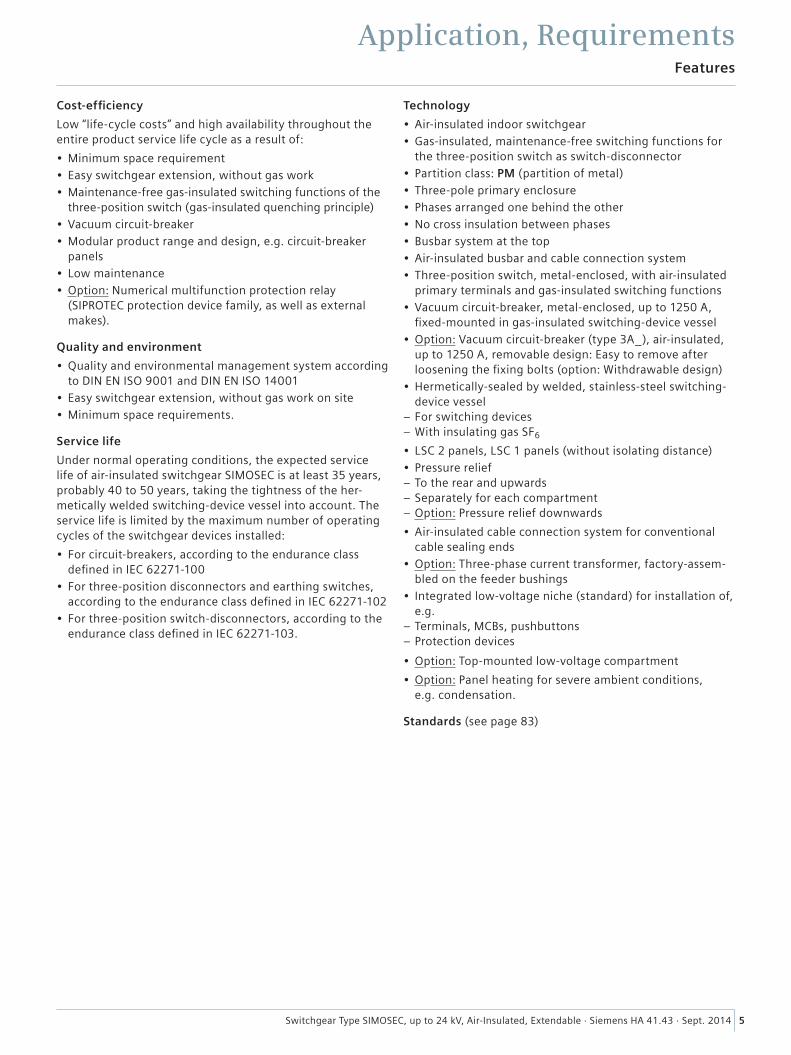
Cost-efficiency
Low “life-cycle costs” and high availability throughout the entire product service life cycle as a result of:
• Minimum space requirement• Easy switchgear extension, without gas work• Maintenance-free gas-insulated switching functions of the
three-position switch (gas-insulated quenching principle)• Vacuum circuit-breaker• Modular product range and design, e.g. circuit-breaker
panels• Low maintenance• Option: Numerical multifunction protection relay
(SIPROTEC protection device family, as well as external makes).
Quality and environment
• Quality and environmental management system according to DIN EN ISO 9001 and DIN EN ISO 14001
• Easy switchgear extension, without gas work on site• Minimum space requirements.
Service life
Under normal operating conditions, the expected service life of air-insulated switchgear SIMOSEC is at least 35 years, probably 40 to 50 years, taking the tightness of the her-metically welded switching-device vessel into account. The service life is limited by the maximum number of operating cycles of the switchgear devices installed:
• For circuit-breakers, according to the endurance class defined in IEC 62271-100
• For three-position disconnectors and earthing switches, according to the endurance class defined in IEC 62271-102
• For three-position switch-disconnectors, according to the endurance class defined in IEC 62271-103.
Technology
• Air-insulated indoor switchgear• Gas-insulated, maintenance-free switching functions for
the three-position switch as switch-disconnector• Partition class: PM (partition of metal)• Three-pole primary enclosure• Phases arranged one behind the other• No cross insulation between phases• Busbar system at the top• Air-insulated busbar and cable connection system• Three-position switch, metal-enclosed, with air-insulated
primary terminals and gas-insulated switching functions• Vacuum circuit-breaker, metal-enclosed, up to 1250 A,
fixed-mounted in gas-insulated switching-device vessel• Option: Vacuum circuit-breaker (type 3A_), air-insulated,
up to 1250 A, removable design: Easy to remove after loosening the fixing bolts (option: Withdrawable design)
• Hermetically-sealed by welded, stainless-steel switching-device vessel
– For switching devices – With insulating gas SF6
• LSC 2 panels, LSC 1 panels (without isolating distance)• Pressure relief
– To the rear and upwards – Separately for each compartment – Option: Pressure relief downwards
• Air-insulated cable connection system for conventional cable sealing ends
• Option: Three-phase current transformer, factory-assem-bled on the feeder bushings
• Integrated low-voltage niche (standard) for installation of, e.g.
– Terminals, MCBs, pushbuttons – Protection devices
• Option: Top-mounted low-voltage compartment
• Option: Panel heating for severe ambient conditions, e.g. condensation.
Standards (see page 83)
6 Switchgear Type SIMOSEC, up to 24 kV, Air-Insulated, Extendable · Siemens HA 41.43 · Sept. 2014
Features, classification
Application, Requirements
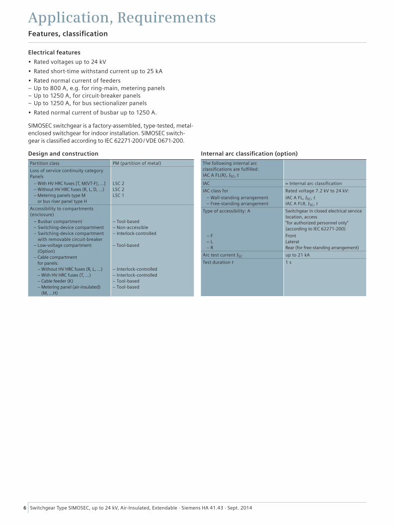
Electrical features
• Rated voltages up to 24 kV
• Rated short-time withstand current up to 25 kA
• Rated normal current of feeders – Up to 800 A, e.g. for ring-main, metering panels – Up to 1250 A, for circuit-breaker panels – Up to 1250 A, for bus sectionalizer panels
• Rated normal current of busbar up to 1250 A.
SIMOSEC switchgear is a factory-assembled, type-tested, metal-enclosed switchgear for indoor installation. SIMOSEC switch-gear is classified according to IEC 62271-200 / VDE 0671-200.
Design and construction
Partition class PM (partition of metal)
Loss of service continuity category Panels
– With HV HRC fuses [T, M(VT-F), ...] – Without HV HRC fuses (R, L, D, ...) – Metering panels type M
or bus riser panel type H
LSC 2 LSC 2 LSC 1
Accessibility to compartments (enclosure)
– Busbar compartment – Switching-device compartment – Switching-device compartment
with removable circuit-breaker – Low-voltage compartment
(Option) – Cable compartment
for panels: – Without HV HRC fuses (R, L, ...) – With HV HRC fuses (T, ...) – Cable feeder (K) – Metering panel (air-insulated)
(M, ...H)
– Tool-based – Non-accessible – Interlock-controlled – Tool-based – Interlock-controlled – Interlock-controlled – Tool-based – Tool-based
Internal arc classification (option)
The following internal arc classifications are fulfilled: IAC A FL(R), ISC, t
IAC = Internal arc classification
IAC class for
– Wall-standing arrangement – Free-standing arrangement
Rated voltage 7.2 kV to 24 kV:
IAC A FL, ISC, t IAC A FLR, ISC, t
Type of accessibility: A
– F – L – R
Switchgear in closed electrical service location, access “for authorized personnel only” (according to IEC 62271-200)
Front Lateral Rear (for free-standing arrangement)
Arc test current ISC up to 21 kA
Test duration t 1 s
7Switchgear Type SIMOSEC, up to 24 kV, Air-Insulated, Extendable · Siemens HA 41.43 · Sept. 2014
Electrical data of the switchgear
Technical Data
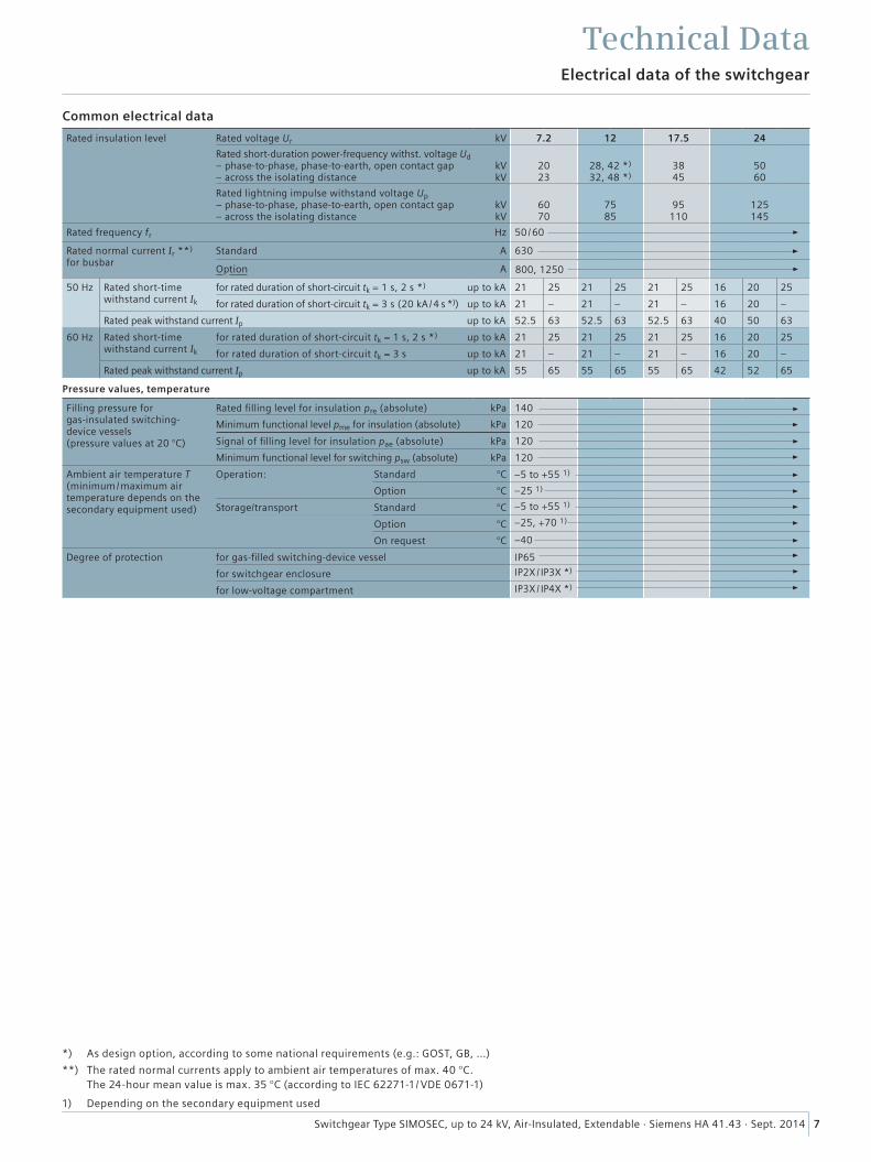
1) Depending on the secondary equipment used
*) As design option, according to some national requirements (e.g.: GOST, GB, …)
**) The rated normal currents apply to ambient air temperatures of max. 40 °C. The 24-hour mean value is max. 35 °C (according to IEC 62271-1/ VDE 0671-1)
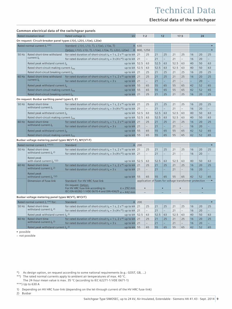
Common electrical data
Rated insulation level Rated voltage Ur kV 7.2 12 17.5 24
Rated short-duration power- frequency withst. voltage Ud – phase-to-phase, phase-to-earth, open contact gap– across the isolating distance
kV kV
2023
28, 42 *) 32, 48 *)
3845
50 60
Rated lightning impulse withstand voltage Up – phase-to-phase, phase-to-earth, open contact gap– across the isolating distance
kVkV
6070
7585
95
110
125145
Rated frequency fr Hz 50 /60
Rated normal current Ir **)
for busbarStandard A 630
Option A
50 Hz Rated short-time withstand current Ik
for rated duration of short-circuit tk = 1 s, 2 s *) up to kA 21 25 21 25 21 25 16 20 25
for rated duration of short-circuit tk = 3 s (20 kA /4 s *)) up to kA 21 – 21 – 21 – 16 20 –
Rated peak withstand current Ip up to kA 52.5 63 52.5 63 52.5 63 40 50 63
60 Hz Rated short-time withstand current Ik
for rated duration of short-circuit tk = 1 s, 2 s *) up to kA 21 25 21 25 21 25 16 20 25
for rated duration of short-circuit tk = 3 s up to kA 21 – 21 – 21 – 16 20 –
Rated peak withstand current Ip up to kA 55 65 55 65 55 65 42 52 65
Pressure values, temperature
Filling pressure for gas-insulated switching- device vessels (pressure values at 20 °C)
Rated filling level for insulation pre (absolute) kPa 140
Minimum functional level pme for insulation (absolute) kPa 120
Signal of filling level for insulation pae (absolute) kPa 120
Minimum functional level for switching psw (absolute) kPa 120
Ambient air temperature T (minimum/maximum air temperature depends on the secondary equipment used)
Operation: Standard °C
Option °C
Storage/transport Standard °C
Option °C
On request °C
Degree of protection for gas-filled switching-device vessel IP65
for switchgear enclosure
for low-voltage compartment
IP2X / IP3X *)
IP3X / IP4X *)
800, 1250
–40
–25, +70 1)
–25 1)
–5 to +55 1)
–5 to +55 1)
8 Switchgear Type SIMOSEC, up to 24 kV, Air-Insulated, Extendable · Siemens HA 41.43 · Sept. 2014
Electrical data of the switchgear
Technical Data
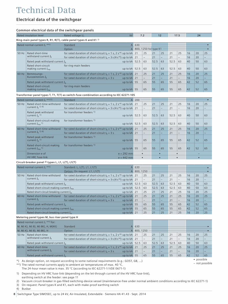
1) Depending on HV HRC fuse-link (depending on the let-through current of the HV HRC fuse-link), earthing switch at the feeder: see page 11 2) Vacuum circuit-breaker in gas-filled switching-device vessel (maintenance-free under normal ambient conditions according to IEC 62271-1) 3) On request: Panel types K and K1, each with make-proof earthing switch 4) Busbar
*) As design option, on request according to some national requirements (e.g.: GOST, GB, …) **) The rated normal currents apply to ambient air temperatures of max. 40 °C. The 24-hour mean value is max. 35 °C (according to IEC 62271-1/ VDE 0671-1)
Common electrical data of the switchgear panels
Rated insulation level Rated voltage Ur kV 7.2 12 17.5 24
Ring-main panel types R, R1, R(T), cable panel types K and K1 3)
Rated normal current Ir **) Standard A 630
Option A
50 Hz Rated short-time withstand current Ik
for rated duration of short-circuit tk = 1 s, 2 s *) up to kA 21 25 21 25 21 25 16 20 25
for rated duration of short-circuit tk = 3 s (4 s *)) up to kA 21 – 21 – 21 – 16 20 –
Rated peak withstand current Ip up to kA 52.5 63 52.5 63 52.5 63 40 50 63
Rated short-circuit making current Ima
for ring-main feeders up to kA
52.5
63
52.5
63
52.5
63
40
50
63
60 Hz Bemessungs- Kurzzeitstrom Ik
for rated duration of short-circuit tk = 1 s, 2 s *) up to kA 21 25 21 25 21 25 16 20 25
for rated duration of short-circuit tk = 3 s up to kA 21 – 21 – 21 – 16 20 –
Rated peak withstand current Ip up to kA 55 65 55 65 55 65 42 52 65
Rated short-circuit making current Ima
for ring-main feeders up to kA
55
65
55
65
55
65
42
52
65
Transformer panel types T, T1, T(T) as switch-fuse combination according to IEC 62271-105
Rated normal current Ir **)1) Standard A 200
50 Hz Rated short-time withstand current Ik
1) 4)for rated duration of short-circuit tk = 1 s, 2 s *) up to kA 21 25 21 25 21 25 16 20 25
for rated duration of short-circuit tk = 3 s (4 s *)) up to kA 21 – 21 – 21 – 16 20 –
Rated peak withstand current Ip
1)for transformer feeders 1) up to kA
52.5
63
52.5
63
52.5
63
40
50
63
Rated short-circuit making current Ima
1)for transformer feeders 1) up to kA
52.5
63
52.5
63
52.5
63
40
50
63
60 Hz Rated short-time withstand current Ik
1) 4)for rated duration of short-circuit tk = 1 s, 2 s *) up to kA 21 25 21 25 21 25 16 20 25
for rated duration of short-circuit tk = 3 s up to kA 21 – 21 – 21 – 16 20 –
Rated peak withstand current Ip
1)for transformer feeders 1) up to kA
55
65
55
65
55
65
42
52
65
Rated short-circuit making current Ima
1)for transformer feeders 1) up to kA
55
65
55
65
55
65
42
52
65
Dimension e ofHV HRC fuse-link
e = 292 mm • • • –
e = 442 mm • • • •
Circuit-breaker panel 2) types L, L1, L(T), L1(T)
Rated normal current Ir **) Standard: L, L(T), L1, L1(T) A 630
Option: On request: L1, L1(T) A 800, 1250
50 Hz Rated short-time withstand current Ik
for rated duration of short-circuit tk = 1 s, 2 s *) up to kA 21 25 21 25 21 25 16 20 25
for rated duration of short-circuit tk = 3 s (4 s *)) up to kA 21 – 21 – 21 – 16 20 –
Rated peak withstand current Ip up to kA 52.5 63 52.5 63 52.5 63 40 50 63
Rated short-circuit making current Ima up to kA 52.5 63 52.5 63 52.5 63 40 50 63
Rated short-circuit breaking current Isc up to kA 21 25 21 25 21 25 16 20 25
60 Hz Rated short-time withstand current Ik
for rated duration of short-circuit tk = 1 s, 2 s *) up to kA 21 25 21 25 21 25 16 20 25
for rated duration of short-circuit tk = 3 s up to kA 21 – 21 – 21 – 16 20 –
Rated peak withstand current Ip up to kA 55 65 55 65 55 65 42 52 65
Rated short-circuit making current Ima up to kA 55 65 55 65 55 65 42 52 65
Rated short-circuit breaking current Isc up to kA 21 25 21 25 21 25 16 20 25
Metering panel types M, bus riser panel type H
Rated normal current Ir **) for:
M, M(-K), M(-B), M(-BK), H, M(KK) Standard A 630
M, M(-K), M(-B), M(-BK), H Option A 800, 1250
50 Hz Rated short-time withstand current Ik
for rated duration of short-circuit tk = 1 s, 2 s *) up to kA 21 25 21 25 21 25 16 20 25
for rated duration of short-circuit tk = 3 s (4 s *)) up to kA 21 – 21 – 21 – 16 20 –
Rated peak withstand current Ip up to kA 52.5 63 52.5 63 52.5 63 40 50 63
60 Hz Rated short-time withstand current Ik
for rated duration of short-circuit tk = 1 s, 2 s *) up to kA 21 25 21 25 21 25 16 20 25
for rated duration of short-circuit tk = 3 s up to kA 21 – 21 – 21 – 16 20 –
Rated peak withstand current Ip up to kA 55 65 55 65 55 65 42 52 65
800, 1250 for type K1
• possible – not possible
9Switchgear Type SIMOSEC, up to 24 kV, Air-Insulated, Extendable · Siemens HA 41.43 · Sept. 2014
Electrical data of the switchgear
Technical Data
Common electrical data of the switchgear panels
Rated insulation level Rated voltage Ur kV 7.2 12 17.5 24
On request: Circuit-breaker panel types L1(r), L2(r), L1(w), L2(w)
Rated normal current Ir **) Standard: L1(r), L1(r, T), L1(w), L1(w, T) A 630
Option: L1(r), L1(r, T), L1(w), L1(w, T), L2(r), L2(w) A 800, 1250
50 Hz Rated short-time withstand current Ik
for rated duration of short-circuit tk = 1 s, 2 s *) up to kA 21 25 21 25 21 25 16 20 25
for rated duration of short-circuit tk = 3 s (4 s *)) up to kA 21 – 21 – 21 – 16 20 –
Rated peak withstand current Ip up to kA 52.5 63 52.5 63 52.5 63 40 50 63
Rated short-circuit making current Ima up to kA 52.5 63 52.5 63 52.5 63 40 50 63
Rated short-circuit breaking current Isc up to kA 21 25 21 25 21 25 16 20 25
60 Hz Rated short-time withstand current Ik
for rated duration of short-circuit tk = 1 s, 2 s *) up to kA 21 25 21 25 21 25 16 20 25
for rated duration of short-circuit tk = 3 s up to kA 21 – 21 – 21 – – 20 –
Rated peak withstand current Ip up to kA 55 65 55 65 55 65 42 52 65
Rated short-circuit making current Ima up to kA 55 65 55 65 55 65 42 52 65
Rated short-circuit breaking current Isc up to kA 21 25 21 25 21 25 16 20 25
On request: Busbar earthing panel types E, E1
50 Hz Rated short-time withstand current Ik
for rated duration of short-circuit tk = 1 s, 2 s *) up to kA 21 25 21 25 21 25 16 20 25
for rated duration of short-circuit tk = 3 s (4 s *)) up to kA 21 – 21 – 21 – 16 20 –
Rated peak withstand current Ip up to kA 52.5 63 52.5 63 52.5 63 40 50 63
Rated short-circuit making current Ima up to kA 52.5 63 52.5 63 52.5 63 40 50 63
60 Hz Rated short-time withstand current Ik
for rated duration of short-circuit tk = 1 s, 2 s *) up to kA 21 25 21 25 21 25 16 20 25
for rated duration of short-circuit tk = 3 s up to kA 21 – 21 – 21 – 16 20 –
Rated peak withstand current Ip up to kA 55 65 55 65 55 65 42 52 65
Rated short-circuit making current Ima up to kA 55 65 55 65 55 65 42 52 65
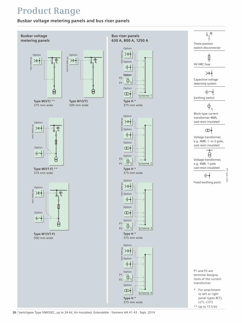
Busbar voltage metering panel types M(VT-F), M1(VT-F)
Rated normal current Ir **)1) Standard A 200
50 Hz Rated short-time withstand current Ik
2)for rated duration of short-circuit tk = 1 s, 2 s *) up to kA 21 25 21 25 21 25 16 20 25
for rated duration of short-circuit tk = 3 s (4 s *)) up to kA 21 – 21 – 21 – 16 20 –
Rated peak with-stand current Ip
1)2) up to kA
52.5
63
52.5
63
52.5
63
40
50
63
60 Hz Rated short-time withstand current Ik
2)for rated duration of short-circuit tk = 1 s, 2 s *) up to kA 21 25 21 25 21 25 16 20 25
for rated duration of short-circuit tk = 3 s up to kA 21 – 21 – 21 – 16 20 –
Rated peak withstand current Ip
1)2) up to kA
55
65
55
65
55
65
42
52
65
Dimension of fuse-link Standard: For HV HRC fuse-link
On request: Option: For HV HRC fuse-link according to IEC /EN 60282-1 /VDE 0670-4 and DIN 43625
•
•
•
•
– – – –
Busbar voltage metering panel types M(VT), M1(VT)
Rated normal current Ir **) for: Standard A 200
50 Hz Rated short-time withstand current Ik
2)for rated duration of short-circuit tk = 1 s, 2 s *) up to kA 21 25 21 25 21 25 16 20 25
for rated duration of short-circuit tk = 3 s (4 s *)) up to kA 21 – 21 – 21 – 16 20 –
Rated peak withstand current Ip 2) up to kA 52.5 63 52.5 63 52.5 63 40 50 63
60 Hz Rated short-time withstand current Ik
2)for rated duration of short-circuit tk = 1 s, 2 s *) up to kA 21 25 21 25 21 25 16 20 25
for rated duration of short-circuit tk = 3 s up to kA 21 – 21 – 21 – 16 20 –
Rated peak withstand current Ip 2) up to kA 55 65 55 65 55 65 42 52 65
application of fuses for voltage transformer protection
e = 292 mm
e = 442 mm
• possible – not possible
1) Depending on HV HRC fuse-link (depending on the let-through current of the HV HRC fuse-link) 2) Busbar
*) As design option, on request according to some national requirements (e.g.: GOST, GB, …) **) The rated normal currents apply to ambient air temperatures of max. 40 °C. The 24-hour mean value is max. 35 °C (according to IEC 62271-1/ VDE 0671-1) ***) Up to 630 A
10 Switchgear Type SIMOSEC, up to 24 kV, Air-Insulated, Extendable · Siemens HA 41.43 · Sept. 2014
Electrical data of the switchgear
Technical Data
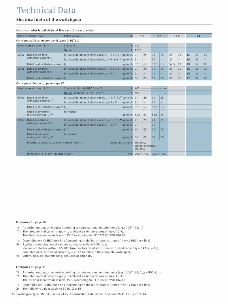
Footnotes for page 10
*) As design option, on request according to some national requirements (e.g.: GOST, GB, …) **) The rated normal currents apply to ambient air temperatures of max. 40 °C. The 24-hour mean value is max. 35 °C (according to IEC 62271-1/ VDE 0671-1)
1) Depending on HV HRC fuse-link (depending on the let-through current of the HV HRC fuse-link) 3) Applies to combination of vacuum contactor with HV HRC fuses: Vacuum contactor without HV HRC fuse reaches rated short-time withstand current Ik = 8 kA (tk = 1 s) and rated peak withstand current Ip = 20 kA (applies to the complete switchgear) 4) Extension tube (150 mm long) required additionally
Footnotes for page 11
*) As design option, on request according to some national requirements (e.g.: GOST, GB, Iload = 800 A, ...) **) The rated normal currents apply to ambient air temperatures of max. 40 °C. The 24-hour mean value is max. 35 °C (according to IEC 62271-1/ VDE 0671-1)
1) Depending on HV HRC fuse-link (depending on the let-through current of the HV HRC fuse-link) 2) The following values apply to 60 Hz: 2 or E1
Common electrical data of the switchgear panels
Rated insulation level Rated voltage Ur kV 7.2 12 17.5 24
On request: Disconnector panel types D, D(T), D1
Rated normal current Ir **) Standard A 630
Option A 1250
50 Hz Rated short-time withstand current Ik
for rated duration of short-circuit tk = 1 s, 2 s *) up to kA 21 25 21 25 21 25 16 20 25
for rated duration of short-circuit tk = 3 s (4 s *)) up to kA 21 – 21 – 21 – 16 20 –
Rated peak withstand current Ip up to kA 52.5 63 52.5 63 52.5 63 40 50 63
60 Hz Rated short-time withstand current Ik
for rated duration of short-circuit tk = 1 s, 2 s *) up to kA 21 25 21 25 21 25 16 20 25
for rated duration of short-circuit tk = 3 s up to kA 21 – 21 – 21 – 16 20 –
Rated peak withstand current Ip up to kA 55 65 55 65 55 65 42 52 65
On request: Contactor panel type VC
Rated normal current Ir **) Standard: With HV HRC fuses 1) A 400
Option: Without HV HRC fuses 3) A 400
50 Hz Rated short-time withstand current Ik
3)for rated duration of short-circuit tk = 1 s 3), 2 s *) up to kA 21 25 21 25
for rated duration of short-circuit tk = 3 s 3) up to kA 21 – 21 –
Rated peak withstand current Ip 1) up to kA 52.5 63 52.5 63
Rated short-circuit making current Ima
1) for feeder up to kA
52.5
63
52.5
63
60 Hz Rated short-time withstand current Ik 3)
for rated duration of short-circuit tk = 1 s 3), 2 s *) up to kA 21 25 21 25
for rated duration of short-circuit tk = 3 s 3) up to kA 21 – 21 –
Rated peak withstand current Ip 1) up to kA 55 65 55 65
Rated short-circuit making current Ima
1) for feeder up to kA
55
65
55
65
Electrical endurance at rated normal current: operating cycles n
Dimension “e” of HV HRC fuse-links 4) mm 292 4), 442 292 4), 442
100,000, option on request: 500,000
11Switchgear Type SIMOSEC, up to 24 kV, Air-Insulated, Extendable · Siemens HA 41.43 · Sept. 2014
Technical data, switching capacity and classification of switching devices
Technical Data
For footnotes, see page 10
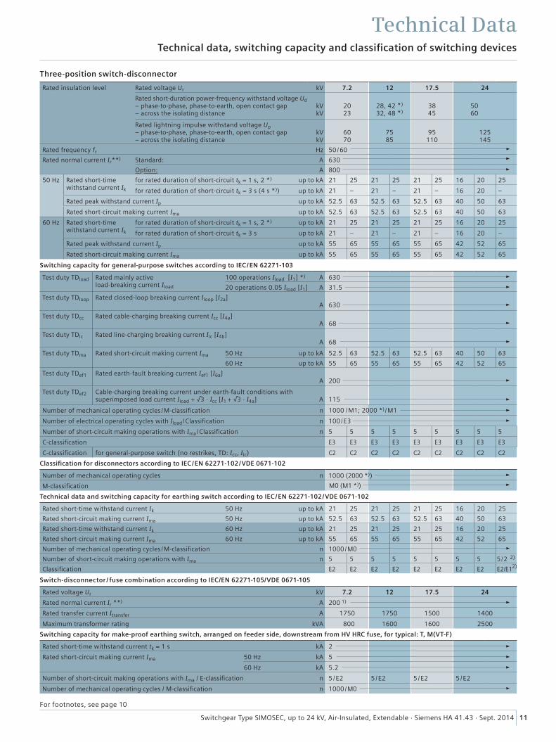
Three-position switch-disconnector
Rated insulation level Rated voltage Ur kV 7.2 12 17.5 24
Rated short-duration power- frequency withstand voltage Ud – phase-to-phase, phase-to-earth, open contact gap– across the isolating distance
kVkV
20 23
28, 42 *)
32, 48 *)
38 45
5060
Rated lightning impulse withstand voltage Up – phase-to-phase, phase-to-earth, open contact gap– across the isolating distance
kV kV
60 70
75 85
95
110
125 145
Rated frequency fr Hz 50 /60
Rated normal current Ir**) Standard: A 630
Option: A 800
50 Hz Rated short-time withstand current Ik
for rated duration of short-circuit tk = 1 s, 2 *) up to kA 21 25 21 25 21 25 16 20 25
for rated duration of short-circuit tk = 3 s (4 s *)) up to kA 21 – 21 – 21 – 16 20 –
Rated peak withstand current Ip up to kA 52.5 63 52.5 63 52.5 63 40 50 63
Rated short-circuit making current Ima up to kA 52.5 63 52.5 63 52.5 63 40 50 63
60 Hz Rated short-time withstand current Ik
for rated duration of short-circuit tk = 1 s, 2 *) up to kA 21 25 21 25 21 25 16 20 25
for rated duration of short-circuit tk = 3 s up to kA 21 – 21 – 21 – 16 20 –
Rated peak withstand current Ip up to kA 55 65 55 65 55 65 42 52 65
Rated short-circuit making current Ima up to kA 55 65 55 65 55 65 42 52 65
Switching capacity for general-purpose switches according to IEC /EN 62271-103
Test duty TDload Rated mainly active load-breaking current Iload
100 operations Iload [I1] *) A 630
20 operations 0.05 Iload [I1] A 31.5
Test duty TDloop Rated closed-loop breaking current Iloop [I2a] A
630
Test duty TDcc Rated cable-charging breaking current Icc [I4a] A
68
Test duty TDlc Rated line-charging breaking current Ilc [I4b] A
68
Test duty TDma Rated short-circuit making current Ima 50 Hz up to kA 52.5 63 52.5 63 52.5 63 40 50 63
60 Hz up to kA 55 65 55 65 55 65 42 52 65
Test duty TDef1 Rated earth-fault breaking current Ief1 [I6a] A
200
Test duty TDef2 Cable-charging breaking current under earth-fault conditions with superimposed load current Iload + √3 · Icc [I1 + √3 · I4a]
A
115
Number of mechanical operating cycles /M-classification n
Number of electrical operating cycles with Iload/Classification n 100/E3
Number of short-circuit making operations with Ima/Classification n 5 5 5 5 5 5 5 5 5
C-classification E3 E3 E3 E3 E3 E3 E3 E3 E3
C-classification for general-purpose switch (no restrikes, TD: Icc, Ilc) C2 C2 C2 C2 C2 C2 C2 C2 C2
Classification for disconnectors according to IEC /EN 62271-102 /VDE 0671-102
Number of mechanical operating cycles n
M-classification
Technical data and switching capacity for earthing switch according to IEC /EN 62271-102 /VDE 0671-102
Rated short-time withstand current Ik 50 Hz up to kA 21 25 21 25 21 25 16 20 25
Rated short-circuit making current Ima 50 Hz up to kA 52.5 63 52.5 63 52.5 63 40 50 63
Rated short-time withstand current Ik 60 Hz up to kA 21 25 21 25 21 25 16 20 25
Rated short-circuit making current Ima 60 Hz up to kA 55 65 55 65 55 65 42 52 65
Number of mechanical operating cycles /M-classification n 1000/M0
Number of short-circuit making operations with Ima n 5 5 5 5 5 5 5 5 5/2
Classification E2 E2 E2 E2 E2 E2 E2 E2 E2/E1
1000 /M1; 2000 *)/M1
1000 (2000 *))
M0 (M1 *))
Switch-disconnector / fuse combination according to IEC/EN 62271-105/VDE 0671-105
Rated voltage Ur kV 7.2 12 17.5 24
Rated normal current Ir **) A 200 1)
Rated transfer current Itransfer A 1750 1750 1500 1400
Maximum transformer rating kVA 800 1600 1600 2500
Switching capacity for make-proof earthing switch, arranged on feeder side, downstream from HV HRC fuse, for typical: T, M(VT-F)
Rated short-time withstand current tk = 1 s kA 2
Rated short-circuit making current Ima 50 Hz kA 5
60 Hz kA 5.2
Number of short-circuit making operations with Ima / E-classification n 5 /E2 5 /E2 5 /E2 5 /E2
Number of mechanical operating cycles / M-classification n 1000 /M0
2)
2)
12 Switchgear Type SIMOSEC, up to 24 kV, Air-Insulated, Extendable · Siemens HA 41.43 · Sept. 201412
Technical data, switching capacity and classification of switching devices
Technical Data
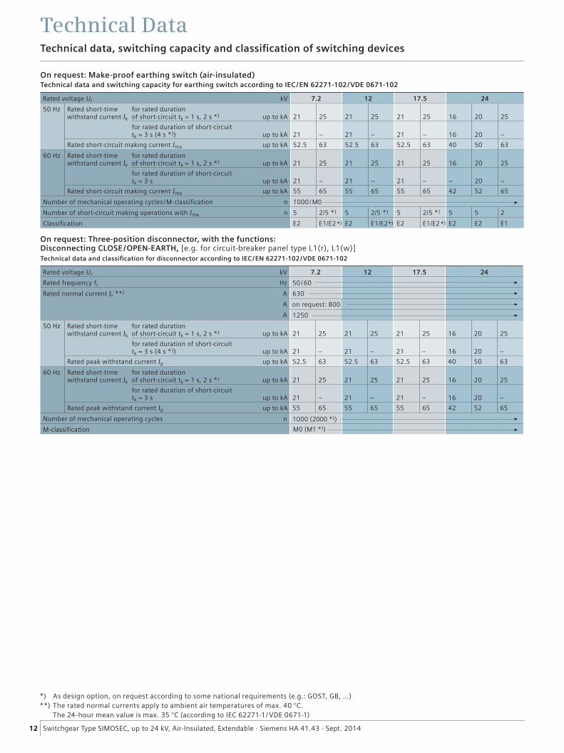
*) As design option, on request according to some national requirements (e.g.: GOST, GB, …) **) The rated normal currents apply to ambient air temperatures of max. 40 °C.
The 24-hour mean value is max. 35 °C (according to IEC 62271-1/ VDE 0671-1)
On request: Make-proof earthing switch (air-insulated) Technical data and switching capacity for earthing switch according to IEC /EN 62271-102 /VDE 0671-102
Rated voltage Ur kV 7.2 12 17.5 24
50 Hz Rated short-time withstand current Ik
for rated duration of short-circuit tk = 1 s, 2 s *) up to kA
21
25
21
25
21
25
16
20
25
for rated duration of short-circuit tk = 3 s (4 s *)) up to kA
21
–
21
–
21
–
16
20
–
Rated short-circuit making current Ima up to kA 52.5 63 52.5 63 52.5 63 40 50 63
60 Hz Rated short-time withstand current Ik
for rated duration of short-circuit tk = 1 s, 2 s *) up to kA
21
25
21
25
21
25
16
20
25
for rated duration of short-circuit tk = 3 s up to kA
21
–
21
–
21
–
–
20
–
Rated short-circuit making current Ima up to kA 55 65 55 65 55 65 42 52 65
Number of mechanical operating cycles /M-classification n 1000/M0
Number of short-circuit making operations with Ima n 5 2/5 *) 5 2/5 *) 5 2/5 *) 5 5 2
Classification E2 E1/E2 E2 E1/E2 E2 E1/E2 E2 E2 E1
On request: Three-position disconnector, with the functions: Disconnecting CLOSE/OPEN-EARTH, [e.g. for circuit-breaker panel type L1(r), L1(w)]Technical data and classification for disconnector according to IEC /EN 62271-102 /VDE 0671-102
Rated voltage Ur kV 7.2 12 17.5 24
Rated frequency fr Hz 50 /60
Rated normal current Ir **) A 630
A
A 1250
50 Hz Rated short-time withstand current Ik
for rated duration of short-circuit tk = 1 s, 2 s *) up to kA
21
25
21
25
21
25
16
20
25
for rated duration of short-circuit tk = 3 s (4 s *)) up to kA
21
–
21
–
21
–
16
20
–
Rated peak withstand current Ip up to kA 52.5 63 52.5 63 52.5 63 40 50 63
60 Hz Rated short-time withstand current Ik
for rated duration of short-circuit tk = 1 s, 2 s *) up to kA
21
25
21
25
21
25
16
20
25
for rated duration of short-circuit tk = 3 s up to kA
21
–
21
–
21
–
16
20
–
Rated peak withstand current Ip up to kA 55 65 55 65 55 65 42 52 65
Number of mechanical operating cycles n
M-classification
on request: 800
*)*)*)
1000 (2000 *))
M0 (M1 *))
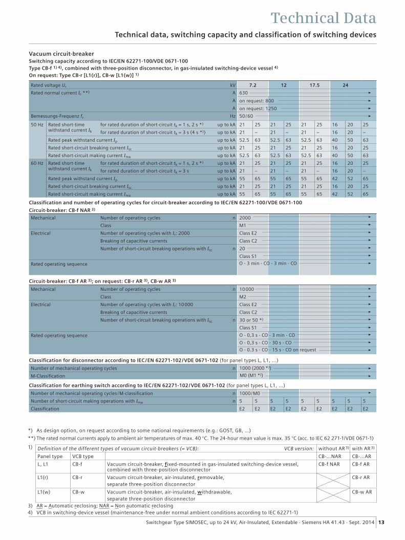
13Switchgear Type SIMOSEC, up to 24 kV, Air-Insulated, Extendable · Siemens HA 41.43 · Sept. 2014 13
Technical data, switching capacity and classification of switching devices
Technical Data
*) As design option, on request according to some national requirements (e.g.: GOST, GB, …)
**) The rated normal currents apply to ambient air temperatures of max. 40 °C. The 24-hour mean value is max. 35 °C (acc. to IEC 62 271-1/VDE 0671-1)
1) Definition of the different types of vacuum circuit-breakers (= VCB): VCB version: without AR 3) with AR 3)
Panel type VCB type CB-...NAR CB-...AR
L, L1 CB-f Vacuum circuit-breaker, fixed-mounted in gas-insulated switching-device vessel, combined with three-position disconnector
CB-f NAR CB-f AR
L1(r) CB-r Vacuum circuit-breaker, air-insulated, removable, separate three-position disconnector
CB-r AR
L1(w) CB-w Vacuum circuit-breaker, air-insulated, withdrawable, separate three-position disconnector
CB-w AR
3) AR = Automatic reclosing; NAR = Non automatic reclosing 4) VCB in switching-device vessel (maintenance-free under normal ambient conditions according to IEC 62271-1)
Vacuum circuit-breakerSwitching capacity according to IEC/EN 62271-100/VDE 0671-100Type CB-f 1) 4), combined with three-position disconnector, in gas-insulated switching-device vessel 4)
On request: Type CB-r [L1(r)], CB-w [L1(w)] 1)
Rated voltage Ur kV 7.2 12 17.5 24
Rated normal current Ir **) A 630
A
A
Bemessungs-Frequenz fr Hz 50 /60
50 Hz Rated short-time withstand current Ik
for rated duration of short-circuit tk = 1 s, 2 s *) up to kA 21 25 21 25 21 25 16 20 25
for rated duration of short-circuit tk = 3 s (4 s *)) up to kA 21 – 21 – 21 – 16 20 –
Rated peak withstand current Ip up to kA 52.5 63 52.5 63 52.5 63 40 50 63
Rated short-circuit breaking current Isc up to kA 21 25 21 25 21 25 16 20 25
Rated short-circuit making current Ima up to kA 52.5 63 52.5 63 52.5 63 40 50 63
60 Hz Rated short-time withstand current Ik
for rated duration of short-circuit tk = 1 s, 2 s *) up to kA 21 25 21 25 21 25 16 20 25
for rated duration of short-circuit tk = 3 s up to kA 21 – 21 – 21 – 16 20 –
Rated peak withstand current Ip up to kA 55 65 55 65 55 65 42 52 65
Rated short-circuit breaking current Isc up to kA 21 25 21 25 21 25 16 20 25
Rated short-circuit making current Ima up to kA 55 65 55 65 55 65 42 52 65
Classification and number of operating cycles for circuit-breaker according to IEC /EN 62271-100 /VDE 0671-100
Circuit-breaker: CB-f NAR 3)
Mechanical Number of operating cycles n 2000
Class M1
Electrical Number of operating cycles with Ir: 2000 Class E2
Breaking of capacitive currents Class C2
Number of short-circuit breaking operations with Isc n 20
Class S1
Rated operating sequence
Circuit-breaker: CB-f AR 3); on request: CB-r AR 3), CB-w AR 3)
Mechanical Number of operating cycles n 10000
Class M2
Electrical Number of operating cycles with Ir: 10000 Class E2
Breaking of capacitive currents Class C2
Number of short-circuit breaking operations with Isc n
Class S1
Rated operating sequence
Classification for disconnector according to IEC / EN 62271-102 /VDE 0671-102 (for panel types L, L1, ...)
Number of mechanical operating cycles n
M-Classification
Classification for earthing switch according to IEC /EN 62271-102 /VDE 0671-102 (for panel types L, L1, ...)
Number of mechanical operating cycles /M-classification n 1000/M0
Number of short-circuit making operations with Ima n 5 5 5 5 5 5 5 5 5
Classification E2 E2 E2 E2 E2 E2 E2 E2 E2
on request: 800
on request: 1250
O - 3 min - CO - 3 min - CO
O - 0,3 s - CO - 3 min - CO
O - 0,3 s - CO - 30 s - CO
O - 0.3 s - CO - 15 s - CO on request
30 or 50 *)
1000 (2000 *))
M0 (M1 *))
14 Switchgear Type SIMOSEC, up to 24 kV, Air-Insulated, Extendable · Siemens HA 41.43 · Sept. 2014
R-H
A41
-117
a.ti
f
Application as:
Panel designation Panel type
Panel width mm
Rated current
R-H
A41
-116
a.ti
f
*) Auf Anfrage
R-H
A41
-13
7a.e
ps
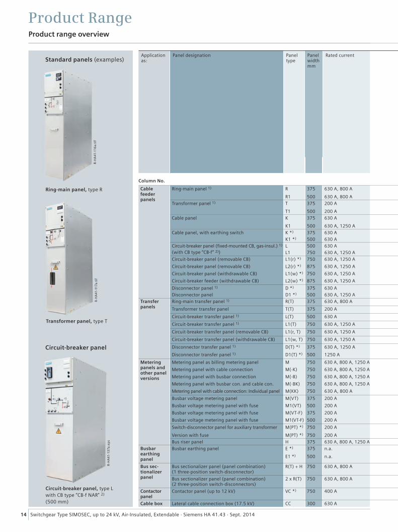
Column No. 1 2 3 4 5 6 7 8 9 10 11 Panel type
Cable feeder panels
Ring-main panel 1) R 375 630 A, 800 A l l*) l l (up to 17.5 kV) – l (up to 17.5 kV)LSC 2
24 kV R
R1 500 630 A, 800 A l l*) l l l l – l 24 kV R1
Transformer panel 1) T 375 200 A l – l – – – –LSC 2
24 kV T
T1 500 200 A l – l – – – – 24 kV T1
Cable panel K 375 630 A l l l (up to 17.5 kV) – l (up to 17.5 kV)LSC 1
24 kV K
K1 500 630 A, 1250 A l l l l l – l 24 kV K1
Cable panel, with earthing switch K *) 375 630 A i.p. l l l (up to 17.5 kV) – l (up to 17.5 kV)LSC 1
24 kV K *)
K1 *) 500 630 A i.p. l l l l l – l 24 kV K1 *)
Circuit-breaker panel (fixed-mounted CB, gas-insul.) 1)
(with CB type “CB-f” 2))L 500 630 A l l l l l l l
LSC 224 kV L
L1 750 630 A, 1250 A i.p.: 1250 A l l l l l l*) l 24 kV L1
Circuit-breaker panel (removable CB) L1(r) *) 750 630 A, 1250 A i.p. l l l l l – l
LSC 2
24 kV L1(r) *)
Circuit-breaker panel (removable CB) L2(r) *) 875 630 A, 1250 A i.p. l l l l l – l 24 kV L2(r) *)
Circuit-breaker panel (withdrawable CB) L1(w) *) 750 630 A, 1250 A i.p. l l l l l – l 24 kV L1(w) *)
Circuit-breaker feeder (withdrawable CB) L2(w) *) 875 630 A, 1250 A i.p. l l l l l l l 24 kV L2(w) *)
Disconnector panel 1) D *) 375 630 A i.p. l l l l –LSC 2
24 kV D *)
Disconnector panel D1 *) 500 630 A, 1250 A i.p. l l l l – 24 kV D1 *)
Transfer panels
Ring-main transfer panel 1) R(T) 375 630 A, 800 A l l – – – LSC 2 24 kV R(T)
Transformer transfer panel T(T) 375 200 A l – – – – – – LSC 2 24 kV T(T)
Circuit-breaker transfer panel 1) L(T) 500 630 A l l l – l l – – LSC 2 24 kV L(T)
Circuit-breaker transfer panel 1) L1(T) 750 630 A, 1250 A i.p.: 1250 A l l – l l – – LSC 2 24 kV L1(T)
Circuit-breaker transfer panel (removable CB) L1(r, T) 750 630 A, 1250 A i.p. l l – l l – – LSC 2 24 kV L1(r, T)
Circuit-breaker transfer panel (withdrawable CB) L1(w, T) 750 630 A, 1250 A i.p. l l – l – – LSC 2 24 kV L1(w, T)
Disconnector transfer panel 1) D(T) *) 375 630 A, 1250 A i.p. l – l – – LSC 2 24 kV D(T) *)
Disconnector transfer panel 1) D1(T) *) 500 1250 A i.p. l – – – LSC 2 24 kV D1(T) *)
Metering panels and other panel versions
Metering panel as billing metering panel M 750 630 A, 800 A, 1250 A l – l – l – –
LSC 1
24 kV M
Metering panel with cable connection M(-K) 750 630 A, 800 A, 1250 A l – l l – 24 kV M(-K)
Metering panel with busbar connection M(-B) 750 630 A, 800 A, 1250 A l – l – l – – 24 kV M(-B)
Metering panel with busbar con. and cable con. M(-BK) 750 630 A, 800 A, 1250 A l – l l – 24 kV M(-BK)
Metering panel with cable connection: Individual panel M(KK) 750 630 A, 800 A l – l l l – 24 kV M(KK)
Busbar voltage metering panel M(VT) 375 200 A l – – – l – –
LSC 2
17.5 kV M(VT)
Busbar voltage metering panel with fuse M1(VT) 500 200 A l – – – l – – 24 kV M1(VT)
Busbar voltage metering panel with fuse M(VT-F) 375 200 A l – – – l – – 17.5 kV M(VT-F)
Busbar voltage metering panel with fuse M1(VT-F) 500 200 A l – – – l – – 24 kV M1(VT-F)
Switch-disconnector panel for auxiliary transformer M(PT) *) 750 200 A i.p. – – – l l – –LSC 2
12 kV M(PT) *)
Version with fuse M(PT) *) 750 200 A i.p. – – – l l – – 12 kV M(PT) *)
Bus riser panel H 375 630 A, 800 A, 1250 A l – l – l – – LSC 1 24 kV HBusbar earthing panel
Busbar earthing panel E *) 375 n.a. i.p. – – – l l – –LSC 1
24 kV E *)
E1 *) 500 n.a. i.p. – – – l l – – 24 kV E1 *)
Bus sec-tionalizer panel
Bus sectionalizer panel (panel combination) (1 three-position switch-disconnector)
R(T) + H 750 630 A, 800 Al l l – l l – –
24 kV R(T) + H
Bus sectionalizer panel (panel combination) (2 three-position switch-disconnectors)
2 x R(T) 750 630 A, 800 Al l l – l – –
24 kV 2 x R(T)
Contactor panel
Contactor panel (up to 12 kV) VC *) 750 400 Ai.p. l *) l l – –
LSC 2 12 kV VC *)
Cable box Lateral cable connection box (17.5 kV) CC 300 630 A i.p. – – – – – – – – LSC 1 12 kV CC
Product range overview
Product Range
Transformer panel, type T
Circuit-breaker panel
Circuit-breaker panel, type Lwith CB type “CB-f NAR” 2)
(500 mm)
Standard panels (examples)
Ring-main panel, type R
15Switchgear Type SIMOSEC, up to 24 kV, Air-Insulated, Extendable · Siemens HA 41.43 · Sept. 2014
LSC
cate
gory
(Los
s of
ser
vice
con
tinui
ty c
ateg
ory)
2nd
cab
le
Rate
d vo
ltage
3rd c
able
Surg
e ar
rest
er in
stea
d of
2nd
cab
le
Thre
e-ph
ase
CTCT
as
cast
-resi
n CT
(e.g
. typ
e 4M
A)
CT a
s ca
ble-
type
CT
VT (1
-pol
e) a
s ca
st-re
sin
VT
VT (2
-pol
e) a
s ca
st-re
sin
VT
P
anel
s in
pre
para
tion
(i.p.
)
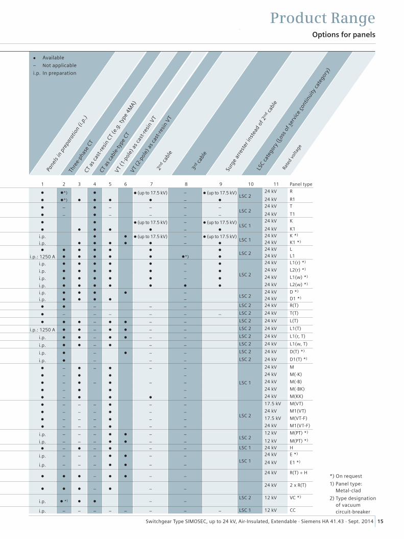
Column No. 1 2 3 4 5 6 7 8 9 10 11 Panel type
Cable feeder panels
Ring-main panel 1) R 375 630 A, 800 A l l*) l l (up to 17.5 kV) – l (up to 17.5 kV)LSC 2
24 kV R
R1 500 630 A, 800 A l l*) l l l l – l 24 kV R1
Transformer panel 1) T 375 200 A l – l – – – –LSC 2
24 kV T
T1 500 200 A l – l – – – – 24 kV T1
Cable panel K 375 630 A l l l (up to 17.5 kV) – l (up to 17.5 kV)LSC 1
24 kV K
K1 500 630 A, 1250 A l l l l l – l 24 kV K1
Cable panel, with earthing switch K *) 375 630 A i.p. l l l (up to 17.5 kV) – l (up to 17.5 kV)LSC 1
24 kV K *)
K1 *) 500 630 A i.p. l l l l l – l 24 kV K1 *)
Circuit-breaker panel (fixed-mounted CB, gas-insul.) 1)
(with CB type “CB-f” 2))L 500 630 A l l l l l l l
LSC 224 kV L
L1 750 630 A, 1250 A i.p.: 1250 A l l l l l l*) l 24 kV L1
Circuit-breaker panel (removable CB) L1(r) *) 750 630 A, 1250 A i.p. l l l l l – l
LSC 2
24 kV L1(r) *)
Circuit-breaker panel (removable CB) L2(r) *) 875 630 A, 1250 A i.p. l l l l l – l 24 kV L2(r) *)
Circuit-breaker panel (withdrawable CB) L1(w) *) 750 630 A, 1250 A i.p. l l l l l – l 24 kV L1(w) *)
Circuit-breaker feeder (withdrawable CB) L2(w) *) 875 630 A, 1250 A i.p. l l l l l l l 24 kV L2(w) *)
Disconnector panel 1) D *) 375 630 A i.p. l l l l –LSC 2
24 kV D *)
Disconnector panel D1 *) 500 630 A, 1250 A i.p. l l l l – 24 kV D1 *)
Transfer panels
Ring-main transfer panel 1) R(T) 375 630 A, 800 A l l – – – LSC 2 24 kV R(T)
Transformer transfer panel T(T) 375 200 A l – – – – – – LSC 2 24 kV T(T)
Circuit-breaker transfer panel 1) L(T) 500 630 A l l l – l l – – LSC 2 24 kV L(T)
Circuit-breaker transfer panel 1) L1(T) 750 630 A, 1250 A i.p.: 1250 A l l – l l – – LSC 2 24 kV L1(T)
Circuit-breaker transfer panel (removable CB) L1(r, T) 750 630 A, 1250 A i.p. l l – l l – – LSC 2 24 kV L1(r, T)
Circuit-breaker transfer panel (withdrawable CB) L1(w, T) 750 630 A, 1250 A i.p. l l – l – – LSC 2 24 kV L1(w, T)
Disconnector transfer panel 1) D(T) *) 375 630 A, 1250 A i.p. l – l – – LSC 2 24 kV D(T) *)
Disconnector transfer panel 1) D1(T) *) 500 1250 A i.p. l – – – LSC 2 24 kV D1(T) *)
Metering panels and other panel versions
Metering panel as billing metering panel M 750 630 A, 800 A, 1250 A l – l – l – –
LSC 1
24 kV M
Metering panel with cable connection M(-K) 750 630 A, 800 A, 1250 A l – l l – 24 kV M(-K)
Metering panel with busbar connection M(-B) 750 630 A, 800 A, 1250 A l – l – l – – 24 kV M(-B)
Metering panel with busbar con. and cable con. M(-BK) 750 630 A, 800 A, 1250 A l – l l – 24 kV M(-BK)
Metering panel with cable connection: Individual panel M(KK) 750 630 A, 800 A l – l l l – 24 kV M(KK)
Busbar voltage metering panel M(VT) 375 200 A l – – – l – –
LSC 2
17.5 kV M(VT)
Busbar voltage metering panel with fuse M1(VT) 500 200 A l – – – l – – 24 kV M1(VT)
Busbar voltage metering panel with fuse M(VT-F) 375 200 A l – – – l – – 17.5 kV M(VT-F)
Busbar voltage metering panel with fuse M1(VT-F) 500 200 A l – – – l – – 24 kV M1(VT-F)
Switch-disconnector panel for auxiliary transformer M(PT) *) 750 200 A i.p. – – – l l – –LSC 2
12 kV M(PT) *)
Version with fuse M(PT) *) 750 200 A i.p. – – – l l – – 12 kV M(PT) *)
Bus riser panel H 375 630 A, 800 A, 1250 A l – l – l – – LSC 1 24 kV HBusbar earthing panel
Busbar earthing panel E *) 375 n.a. i.p. – – – l l – –LSC 1
24 kV E *)
E1 *) 500 n.a. i.p. – – – l l – – 24 kV E1 *)
Bus sec-tionalizer panel
Bus sectionalizer panel (panel combination) (1 three-position switch-disconnector)
R(T) + H 750 630 A, 800 Al l l – l l – –
24 kV R(T) + H
Bus sectionalizer panel (panel combination) (2 three-position switch-disconnectors)
2 x R(T) 750 630 A, 800 Al l l – l – –
24 kV 2 x R(T)
Contactor panel
Contactor panel (up to 12 kV) VC *) 750 400 Ai.p. l *) l l – –
LSC 2 12 kV VC *)
Cable box Lateral cable connection box (17.5 kV) CC 300 630 A i.p. – – – – – – – – LSC 1 12 kV CC
Options for panels
Product Range
*) On request
1) Panel type: Metal-clad
2) Type designation of vacuum circuit-breaker
l Available
– Not applicable
i.p. In preparation
R-H
A41
-119
a.ti
f
R-H
A41
-141
.tif
R-H
A41
-13
9a.
tif
Bus riser paneltype H
16 Switchgear Type SIMOSEC, up to 24 kV, Air-Insulated, Extendable · Siemens HA 41.43 · Sept. 2014
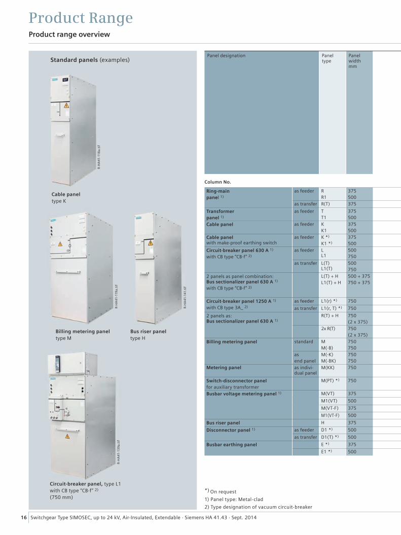
Column No. 1 2 3 4 5 6 7 8 9 10 11 12 13 14 15 16 17 18 19 20 21 22 23 24 25 26 Panel type
Ring-mainpanel 1)
as feeder RR1
375500
l l – l l – l – – – – – –RR1
as transfer R(T) 375 l l – – l – l – – – – – – – – – R(T)
Transformerpanel 1)
as feeder TT1
375500 l l – l l l – l l – – – –
TT1
Cable panel as feeder KK1
375500 – – l l l – – – – – – – – – – – – – –
KK1
Cable panel with make-proof earthing switch
as feeder K *)
K1 *)
375500 l l l l l – l – – – – – – – – l –
K *)
K1 *)
Circuit-breaker panel 630 A 1)
with CB type “CB-f” 2)
as feeder L L1
500750 l l – l l l l – – –
LL1
as transfer L(T) L1(T)
500750 l l – – l l l – – – – – –
L(T)L1(T)
2 panels as panel combination: Bus sectionalizer panel 630 A 1)
with CB type “CB-f” 2)
L(T) + HL1(T) + H
500 + 375750 + 375
l l l – l l l – – – – – –
L(T) + HL1(T) + H
Circuit-breaker panel 1250 A 1)
with CB type 3A_ 2)
as feeder L1(r) *) 750 l l – l l l l – – L1(r) *)
as transfer L1(r, T) *) 750 l l – – l l l – – – – – – L1(r, T) *)
2 panels as: Bus sectionalizer panel 630 A 1)
R(T) + H 750(2 x 375) l l l – l l – – – – – – – – –
R(T) + H
2x R(T) 750(2 x 375) l l – – l – l – – – – – – – – –
2x R(T)
Billing metering panel standard MM(-B)
750 750 – – l – l – – – – – – – – – – – – – – – –
MM(-B)
asend panel
M(-K)M(-BK)
750750 – – l l l – – – – – – – – – – – – – – –
M(-K)M(-BK)
Metering panel as indivi-dual panel
M(KK) 750– – l l l – – – – – – – – – – – – – – –
M(KK)
Switch-disconnector panelfor auxiliary transformer
M(PT) *) 750– – l – l – – – – – – – – – – – – – – – –
M(PT) *)
Busbar voltage metering panel 1) M(VT) 375 l l – – l – – – – – – – – – – M(VT)
M1(VT) 500 l l – – l – – – – – – – – – – M1(VT)
M(VT-F) 375 l l – – l – – – – – – – – – M(VT-F)
M1(VT-F) 500 l l – – l – – – – – – – – – M1(VT-F)
Bus riser panel H 375 – – l – l – – – – – – – – – – – – – – – – – H
Disconnector panel 1) as feeder D1 *) 500 l l – l l – l – – – – – – D1 *)
as transfer D1(T) *) 500 l l – – l – l – – – – – – – – – D1(T) *)
Busbar earthing panel E *) 375 l – l – l – – – – – – – – – – – – – – E *)
E1 *) 500 l – l – l – – – – – – – – – – – – – – E1 *)
1 2 3 4 5 6 7 8 9 10 11 12 13 14 15 16 17 18 19 20 21 22 23 24 25 26 Panel type
Panel designation Panel type
Panel width mm
Product range overview
Product Range
Standard panels (examples)
R-H
A41
-118
a.ti
f
Cable paneltype K
Circuit-breaker panel, type L1 with CB type “CB-f” 2)
(750 mm)
Billing metering paneltype M
*) On request
1) Panel type: Metal-clad
2) Type designation of vacuum circuit-breaker
17Switchgear Type SIMOSEC, up to 24 kV, Air-Insulated, Extendable · Siemens HA 41.43 · Sept. 2014
Man
ual o
pera
ting
mec
hani
sm fo
r thr
ee-p
ositi
on sw
itch
1) 2
) (or e
arth
ing
switc
h)
Inte
rlock
for c
able
com
part
men
t cov
er
Cabl
e co
mpa
rtm
ent c
over
lock
ed in
pla
ce
C-ra
il as
cab
le b
rack
et
Low
-vol
tage
nic
he a
s te
rmin
al c
ompa
rtm
ent
Rele
ase
as s
hunt
rele
ase
Mec
hani
cal r
eady
-for-
serv
ice
indi
cato
r for
thre
e-po
sitio
n sw
itch
Sign
alin
g sw
itch
(1N
O) f
or re
mot
e el
ectr
ical
re
ady-
for-
serv
ice
indi
catio
n fo
r thr
ee-p
ositi
on s
witc
h 1)
Auxi
liary
switc
h fo
r thr
ee-p
ositi
on sw
itch
and
mak
e-pr
oof e
arth
ing
switc
h
Sw
itch-
disc
onne
ctor
and
EAR
THIN
G: For
CLO
SED a
nd O
PEN 2
NO+2
NC ea
ch
Mot
or o
pera
ting
mec
hani
sm fo
r thr
ee-p
ositi
on s
witc
h 1)
2)
Loca
l-rem
ote
switc
h fo
r mot
or o
pera
ting
mec
hani
sm o
f thr
ee-p
ositi
on sw
itch
1) 2
)
Inte
rlock
in c
ircui
t-br
eake
r pan
el b
etw
een
th
ree-
posi
tion
switc
h 1) a
nd v
acuu
m c
ircui
t-br
eake
r
Sprin
g ch
arge
d in
dica
tor (
for s
tore
d-en
ergy
“ON
”/“O
FF”)
Clos
ing
lock
-out
for t
hree
-pos
ition
sw
itch
1)
De-ea
rthi
ng lo
ck-o
ut fo
r mak
e-pr
oof e
arth
ing
switc
h
Insp
ectio
n w
indo
w in
the
conn
ectio
n / c
able
com
part
men
t cov
er
Low
-vol
tage
com
part
men
t or c
over
Mot
or o
pera
ting
mec
hani
sm fo
r vac
uum
circ
uit-
brea
ker
Rele
ase
as c
.t.-o
pera
ted
rele
ase
in v
acuu
m c
ircui
t-br
eake
r 3)
Lock
ing
devi
ce fo
r thr
ee-p
ositi
on s
witc
h 1)
2) o
r ear
thin
g sw
itch
Shor
t-ci
rcui
t or e
arth
-faul
t ind
icat
or
Seco
ndar
y eq
uipm
ent
Floo
r cov
er 4
)Pa
nel h
eatin
g (w
ired
on te
rmin
al)
Lock
ing
devi
ce fo
r sw
itch
posit
ion
“C
LOSE
D” of 3
A_ V
CB w
ith e
arth
ed
thr
ee-p
ositi
on sw
itch
2)
Prem
ount
ed c
able
cla
mps
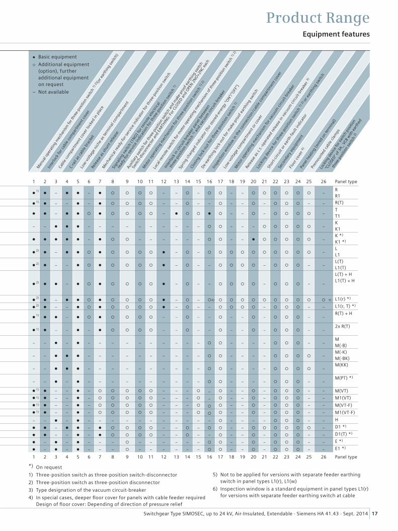
l Basic equipment
Additional equipment (option), further additional equipment on request
– Not available
Column No. 1 2 3 4 5 6 7 8 9 10 11 12 13 14 15 16 17 18 19 20 21 22 23 24 25 26 Panel type
Ring-mainpanel 1)
as feeder RR1
375500
l l – l l – l – – – – – –RR1
as transfer R(T) 375 l l – – l – l – – – – – – – – – R(T)
Transformerpanel 1)
as feeder TT1
375500 l l – l l l – l l – – – –
TT1
Cable panel as feeder KK1
375500 – – l l l – – – – – – – – – – – – – –
KK1
Cable panel with make-proof earthing switch
as feeder K *)
K1 *)
375500 l l l l l – l – – – – – – – – l –
K *)
K1 *)
Circuit-breaker panel 630 A 1)
with CB type “CB-f” 2)
as feeder L L1
500750 l l – l l l l – – –
LL1
as transfer L(T) L1(T)
500750 l l – – l l l – – – – – –
L(T)L1(T)
2 panels as panel combination: Bus sectionalizer panel 630 A 1)
with CB type “CB-f” 2)
L(T) + HL1(T) + H
500 + 375750 + 375
l l l – l l l – – – – – –
L(T) + HL1(T) + H
Circuit-breaker panel 1250 A 1)
with CB type 3A_ 2)
as feeder L1(r) *) 750 l l – l l l l – – L1(r) *)
as transfer L1(r, T) *) 750 l l – – l l l – – – – – – L1(r, T) *)
2 panels as: Bus sectionalizer panel 630 A 1)
R(T) + H 750(2 x 375) l l l – l l – – – – – – – – –
R(T) + H
2x R(T) 750(2 x 375) l l – – l – l – – – – – – – – –
2x R(T)
Billing metering panel standard MM(-B)
750 750 – – l – l – – – – – – – – – – – – – – – –
MM(-B)
asend panel
M(-K)M(-BK)
750750 – – l l l – – – – – – – – – – – – – – –
M(-K)M(-BK)
Metering panel as indivi-dual panel
M(KK) 750– – l l l – – – – – – – – – – – – – – –
M(KK)
Switch-disconnector panelfor auxiliary transformer
M(PT) *) 750– – l – l – – – – – – – – – – – – – – – –
M(PT) *)
Busbar voltage metering panel 1) M(VT) 375 l l – – l – – – – – – – – – – M(VT)
M1(VT) 500 l l – – l – – – – – – – – – – M1(VT)
M(VT-F) 375 l l – – l – – – – – – – – – M(VT-F)
M1(VT-F) 500 l l – – l – – – – – – – – – M1(VT-F)
Bus riser panel H 375 – – l – l – – – – – – – – – – – – – – – – – H
Disconnector panel 1) as feeder D1 *) 500 l l – l l – l – – – – – – D1 *)
as transfer D1(T) *) 500 l l – – l – l – – – – – – – – – D1(T) *)
Busbar earthing panel E *) 375 l – l – l – – – – – – – – – – – – – – E *)
E1 *) 500 l – l – l – – – – – – – – – – – – – – E1 *)
1 2 3 4 5 6 7 8 9 10 11 12 13 14 15 16 17 18 19 20 21 22 23 24 25 26 Panel type
Equipment features
Product Range
*) On request
1) Three-position switch as three-position switch-disconnector
2) Three-position switch as three-position disconnector
3) Type designation of the vacuum circuit-breaker
4) In special cases, deeper floor cover for panels with cable feeder required Design of floor cover: Depending of direction of pressure relief
5) Not to be applied for versions with separate feeder earthing switch in panel types L1(r), L1(w)
6) Inspection window is a standard equipment in panel types L1(r) for versions with separate feeder earthing switch at cable
1)
1)
2)
2)
2)
6) 5)2)
2)
1)
1)
1)
1)
1)
1)
���
����
������
��
��
���
����
������
��
��
��
���
����
������
�
�����
��
��
��
���
����
������
��
18 Switchgear Type SIMOSEC, up to 24 kV, Air-Insulated, Extendable · Siemens HA 41.43 · Sept. 2014
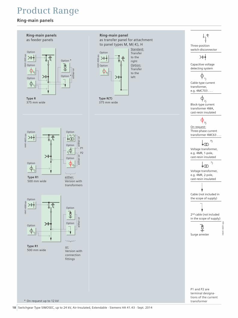
Ring-main panels
Product Range
Ring-main panelsas feeder panels
Type R 375 mm wide
Type R1 500 mm wide
Type R1 500 mm wide
either: Version with transformers
or: Version with connection fittings
Type R(T) 375 mm wide
Standard: Transfer to the rightOption: Transfer to the left
Ring-main panelas transfer panel for attachment to panel types M, M(-K), H
* On request up to 12 kV
Option
Option
Option Option
Option
Option
Option
Option *
Option
OptionOption *
Option
Option
OptionOption
eith
er-o
rei
ther
-or
eith
er-o
r
eith
er-o
r
Option
��
��
��
��
��
HA
41-4
051
ep
s
Capacitive voltage detecting system
Cable-type current transformer, e.g. 4MC703 . . .
Block-type current transformer 4MA, cast-resin insulated
On request: Three-phase current transformer 4MC63 . . .
Voltage transformer, e.g. 4MR, 1-pole, cast-resin insulated
Voltage transformer, e.g. 4MR, 2-pole, cast-resin insulated
Cable (not included in the scope of supply)
2nd cable (not included in the scope of supply)
Surge arrester
P1 and P2 are terminal designa- tions of the current transformer
Three-position switch-disconnector
19Switchgear Type SIMOSEC, up to 24 kV, Air-Insulated, Extendable · Siemens HA 41.43 · Sept. 2014
���
����
����
����
��
���
����
����
����
���
����
����
����
��
���
����
����
����
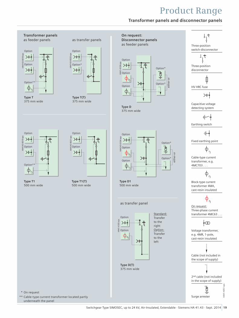
Transformer panels and disconnector panels
Product Range
* On request
** Cable-type current transformer located partly underneath the panel
Transformer panelsas feeder panels as transfer panels
Type T375 mm wide
Type T(T)375 mm wide
Type T1500 mm wide
Type T1(T)500 mm wide
Option
Option
Option
Option
Option
Option**
Option*
Option Option
Option**
Three-position switch-disconnector
��
On request: Three-phase current transformer 4MC63 . . .
��
��
HA
41-4
051
ep
s
HV HRC fuse
Capacitive voltage detecting system
Earthing switch
Fixed earthing point
Cable-type current transformer, e.g. 4MC703 . . .
Block-type current transformer 4MA, cast-resin insulated
Voltage transformer, e.g. 4MR, 1-pole, cast-resin insulated
Cable (not included in the scope of supply)
2nd cable (not included in the scope of supply)
Surge arrester
���
����
������
��
��
On request: Disconnector panelsas feeder panels
Type D 375 mm wide
Option
Option
OptionOption*
Option*
eith
er-o
r
��
���
����
������
Type D(T)375 mm wide
Option
Option
Standard: Transfer to the rightOption: Transfer to the left
as transfer panel
Three-position disconnector
��
��
���
����
����
����
Type D1500 mm wide
Option
Option
OptionOption*
Option*
eith
er-o
r
20 Switchgear Type SIMOSEC, up to 24 kV, Air-Insulated, Extendable · Siemens HA 41.43 · Sept. 2014
���
����
������
��
���
����
������
��
��
��
HA
41-4
051
ep
s
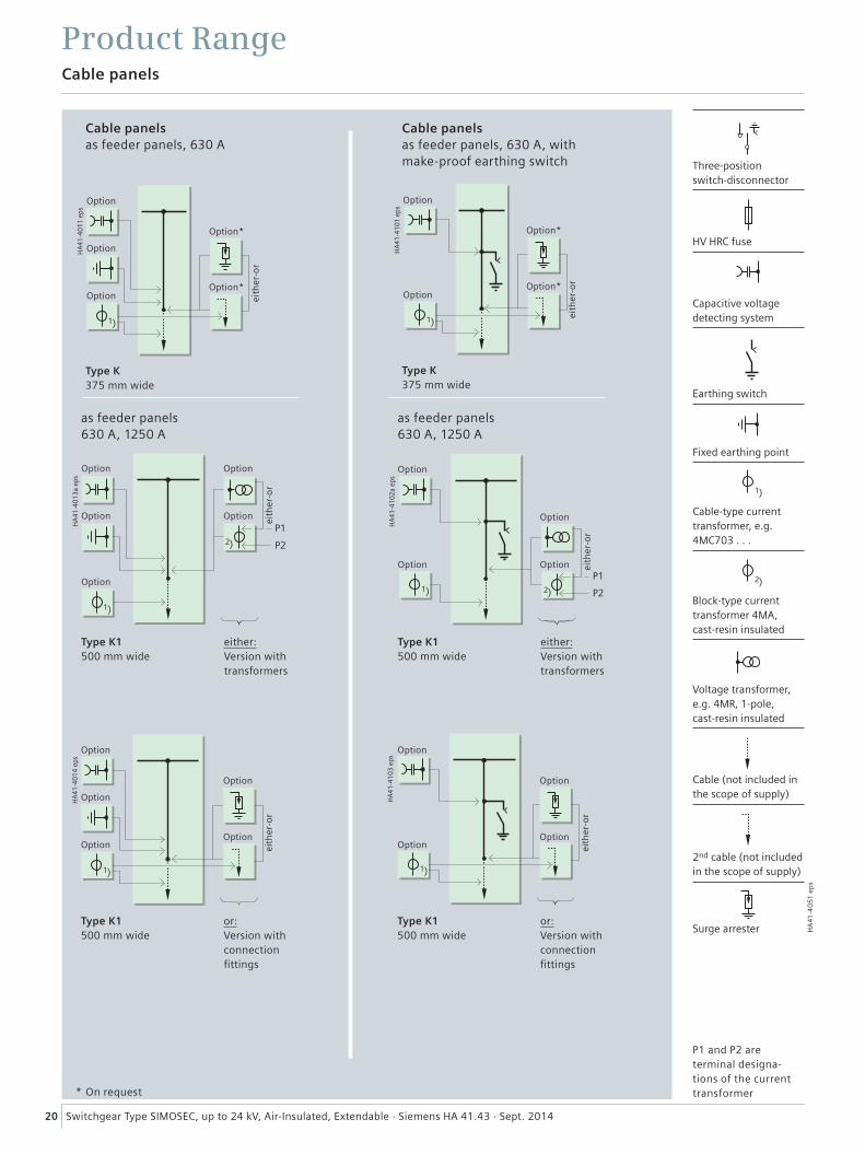
Cable panels
Product Range
* On request
Cable panelsas feeder panels, 630 A
Type K 375 mm wide
Type K1500 mm wide
or:Version withconnectionfittings
Three-position switch-disconnector
HV HRC fuse
Capacitive voltage detecting system
Earthing switch
Fixed earthing point
Cable-type current transformer, e.g. 4MC703 . . .
Block-type current transformer 4MA, cast-resin insulated
Voltage transformer, e.g. 4MR, 1-pole, cast-resin insulated
Cable (not included in the scope of supply)
2nd cable (not included in the scope of supply)
Surge arrester
Option
Option
Option
Option
Option
OptionOption
Option
Option*
Option*
eith
er-o
rei
ther
-or
��
���
����
������
��
���
����
������
Cable panelsas feeder panels, 630 A, with make-proof earthing switch
Type K 375 mm wide
Type K1500 mm wide
or:Version withconnectionfittings
Option
Option
Option
OptionOption
Option
Option*
Option*
eith
er-o
r
���
����
������
�
��
�� ��
��
as feeder panels630 A, 1250 A
Type K1500 mm wide
either:Version withtransformers
Option Option
OptionOption
Option
eith
er-o
r
��
���
����
������
�
�� ��
��
as feeder panels630 A, 1250 A
Type K1500 mm wide
either:Version withtransformers
Option
Option
OptionOption eith
er-o
rei
ther
-or
P1 and P2 are terminal designa- tions of the current transformer
Earthing switch
21Switchgear Type SIMOSEC, up to 24 kV, Air-Insulated, Extendable · Siemens HA 41.43 · Sept. 2014
HA
41-4
051
ep
s
���
����
����
����
���
����
������
�
���
����
����
���
���
����
����
���
���
����
����
����
���
����
������
���
����
����
����
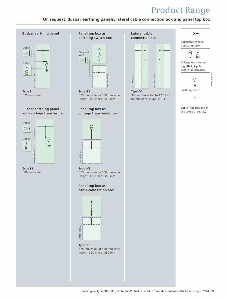
On request: Busbar earthing panels, lateral cable connection box and panel top box
Product Range
Busbar earthing panel with voltage transformer
Panel top box as voltage transfomer box
Panel top box as cable connection box
Busbar earthing panel Panel top box as earthing switch box
Lateral cable connection box
Type E375 mm wide
Type -EB375 mm wide, or 500 mm wide Height: 350 mm or 550 mm
Type CC300 mm wide (up to 17.5 kV) for end panels type: R, T, L
Type E1500 mm wide
Type -VB375 mm wide, or 500 mm wide Height: 350 mm or 550 mm
Type -KB375 mm wide, or 500 mm wide Height: 350 mm or 550 mm
Capacitive voltage detecting system
Voltage transformer, e.g. 4MR, 1-pole, cast-resin insulated
Cable (not included in the scope of supply)
Option
Option
Standard: With
Option
Option
��
���
����
������
��
��
��
��
��
�����
��
���
����
������
��
��
��
��
��
�����
4
��
��
��
��
��
��
HA
41-4
051
ep
s
��
���
����
������
��
��
��
��
�����
��
���
����
������
��
��
��
��
�����
22 Switchgear Type SIMOSEC, up to 24 kV, Air-Insulated, Extendable · Siemens HA 41.43 · Sept. 2014
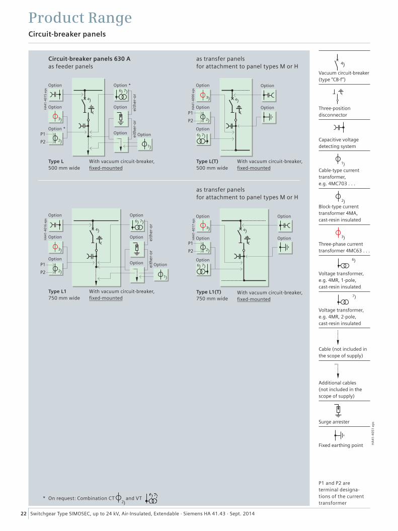
Circuit-breaker panels 630 A as feeder panels
Vacuum circuit-breaker (type “CB-f”)
Three-position disconnector
Capacitive voltage detecting system
Cable-type current transformer, e.g. 4MC703 . . .
Block-type current transformer 4MA, cast-resin insulated
Three-phase current transformer 4MC63 . . .
Voltage transformer, e.g. 4MR, 1-pole, cast-resin insulated
Voltage transformer, e.g. 4MR, 2-pole, cast-resin insulated
Cable (not included in the scope of supply)
Additional cables (not included in the scope of supply)
Surge arrester
Fixed earthing point
Circuit-breaker panels
Product Range
Type L 500 mm wide
Type L1 750 mm wide
With vacuum circuit-breaker,fixed-mounted
With vacuum circuit-breaker,fixed-mounted
Option Option *
Option Option
Option *
Option Option
Option
Option
as transfer panels for attachment to panel types M or H
Type L1(T) 750 mm wide
With vacuum circuit-breaker,fixed-mounted
Option
Option
Option
Option
Option
Option
Option
Option
Option
Option
Option
Option
Option
Option Optioneith
er-o
r
eith
er-o
rei
ther
-or
eith
er-o
r
P1 and P2 are terminal designa- tions of the current transformer
as transfer panels for attachment to panel types M or H
Type L(T) 500 mm wide
With vacuum circuit-breaker,fixed-mounted
* On request: Combination CT and VT
4
���
����
������
����
����
������
���
����
����
�
��
��
��
��
��
�����
��
��
��
HA
41-4
051
ep
s
��
���
����
������
��
��
����
��
�����
���
����
������
��
��
��
��
��
�����
23Switchgear Type SIMOSEC, up to 24 kV, Air-Insulated, Extendable · Siemens HA 41.43 · Sept. 2014
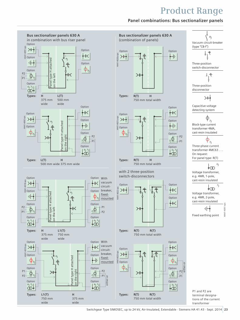
Bus sectionalizer panels 630 A(combination of panels)
with 2 three-position switch-disconnectors
Vacuum circuit-breaker (type “CB-f”)
Three-position switch-disconnector
Three-position disconnector
Block-type current transformer 4MA, cast-resin insulated
Three-phase current transformer 4MC63 . . . On request: For panel type: R(T)
Voltage transformer, e.g. 4MR, 1-pole, cast-resin insulated
Voltage transformer, e.g. 4MR, 2-pole, cast-resin insulated
Fixed earthing point
P1 and P2 are terminal designa- tions of the current transformer
Panel combinations: Bus sectionalizer panels
Product Range
R(T) H 750 mm total width
R(T) R(T)750 mm total width
R(T) R(T)750 mm total width
R(T) H 750 mm total width
Bus sectionalizer panels 630 Ain combination with bus riser panel
Option Option
Option
Option
Option
Option
Option
Option
Option
Option
Option
Option
���
����
������
�
��
��
��
��
�����
Option
Option
Option
Option
Option
OptionOption
Option
Option
Option
Option
Option
Option
Option
Option
Option
Option
���
����
������
��
��
��
��
��
��
��
��
����� �����
With vacuum circuit- breaker, fixed- mounted
L1(T)750 mm wide
H375 mm wide
OptionOption
OptionOption
OptionOption
���
����
������
��
��
��
��
��
��
��
��
����� �����Pan
el t
ype
H a
ttac
hed
on
th
e le
ft
Pan
el t
ype
H a
ttac
hed
on
th
e ri
gh
t
Pan
el t
ype
H a
ttac
hed
on
th
e le
ft
Pan
el t
ype
H a
ttac
hed
on
th
e ri
gh
t
With vacuum circuit- breaker, fixed- mounted
H375 mm wide
L1(T)750 mm wide
Option Option
Option Option
Option Option
Option Option
OptionOption
eith
er-o
r
eith
er-o
r
Capacitive voltage detecting system
L(T) 500 mm wide
H 375 mm wide
H 375 mm wide
L(T) 500 mm wide
Types: Types:
Types:
Types:
Types:
Types:
Types:
Types:
��
���
����
������
��
�� �����
����
������
��
����
��
���
����
����
�
����
��
��
��
��
���
����
������
��
�� ��
���
����
������
��
��
��
��
���
����
������
����
��
��
��
��
���
����
������
��
�� ��
���
����
������
��
��
��
��
���
����
������
����
��
��
��
��
���
����
������
��
�� ��
���
����
������
��
����
��
���
����
������
����
��
��
��
�� ��
��
HA
41-4
051
ep
s
On request:
24 Switchgear Type SIMOSEC, up to 24 kV, Air-Insulated, Extendable · Siemens HA 41.43 · Sept. 2014
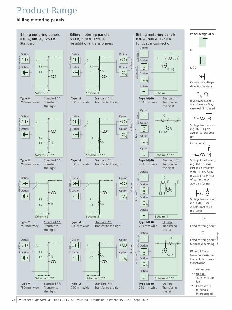
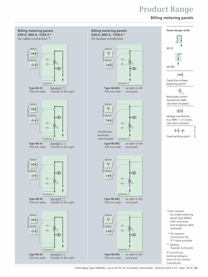
Billing metering panels 630 A, 800 A, 1250 AStandard
Billing metering panels 630 A, 800 A, 1250 Afor additional transformers
Billing metering panels 630 A, 800 A, 1250 Afor busbar connection
Scheme 1 Scheme 1 Scheme 1
Scheme 2 *** Scheme 2 *** Scheme 2 ***
Scheme 3 Scheme 3 Scheme 3
Scheme 4 *** Scheme 4 *** Scheme 4 ***
Capacitive voltage detecting system
Block-type current transformer 4MA, cast-resin insulated
Voltage transformer, e.g. 4MR, 1-pole, cast-resin insulated or:
Voltage transformer, e.g. 4MR, 1-pole, cast-resin insulated, with HV HRC fuse, instead of a 2nd set of current or volt-age transformers
Voltage transformer, e.g. 4MR, 1- or 2-pole, cast-resin insulated
Fixed earthing point
Fixed earthing point for busbar earthing
Panel design of M:
M
M(-B)
P1 and P2 are terminal designa-tions of the current transformer
* On request
** Option: Transfer to the left
*** Transformer terminals interchanged
Billing metering panels
Product Range
Type M 750 mm wide
Type M 750 mm wide
Type M(-B) 750 mm wide
Type M 750 mm wide
Type M 750 mm wide
Type M(-B) 750 mm wide
Type M 750 mm wide
Type M 750 mm wide
Type M(-B) 750 mm wide
Type M 750 mm wide
Type M 750 mm wide
Type M(-B) 750 mm wide
Standard **:Transfer to the right
Standard **:Transfer to the right
Standard **:Transfer to the right
Standard **:Transfer to the right
Standard **:Transfer to the right
Standard **:Transfer to the right
Standard **:Transfer to the right
Standard **:Transfer to the right
Option:Transfer to the left
Standard **:Transfer to the right
Standard **:Transfer to the right
Option:Transfer to the left
Option Option Option
Option Option Option eith
er-o
rei
ther
-or
eith
er-o
rei
ther
-or
Option
Option
Option
Option
Option
Option
Option Option
Option
Option
Option
Option
Option
Option
Option
Option
Option
Option Option
Option
Option
Option
Option
Option
Option
Option
Option Option
Option
Option
Option Option
Option
Option
eith
er-o
r *ei
ther
-or *
eith
er-o
r *ei
ther
-or *
��
���
����
������
��
�� ��
���
����
������
��
��
��
���
����
������
��
�� ��
���
����
������
��
��
��
���
����
������
��
�� ��
���
����
������
��
��
��
���
����
������
��
�� ��
���
����
������
��
��
��
HA
41-4
051
ep
s
25Switchgear Type SIMOSEC, up to 24 kV, Air-Insulated, Extendable · Siemens HA 41.43 · Sept. 2014
P1 and P2 are terminal designa-tions of the current transformer
* On request: Connection for 2nd cable possible
** Option: Transfer to the left
1) On request: As single metering panel type M(KK) with incoming and outgoing cable terminals
Scheme 1 Scheme 1
Scheme 2 Scheme 2
Transformerterminalsinterchanged
Scheme 3 Scheme 3
Scheme 4 Scheme 4
Capacitive voltage detecting system
Block-type current transformer 4MA, cast-resin insulated
Voltage transformer, e.g. 4MR, 1- or 2-pole, cast-resin insulated
Fixed earthing point
Billing metering panels
Product Range
Billing metering panels 630 A, 800 A, 1250 A * for cable connection 1)
Billing metering panels 630 A, 800 A, 1250 A * for busbar connection
Type M(-K) 750 mm wide
Type M(-BK) 750 mm wide
Type M(-K) 750 mm wide
Type M(-BK) 750 mm wide
Type M(-K) 750 mm wide
Type M(-BK) 750 mm wide
Type M(-K) 750 mm wide
Type M(-BK) 750 mm wide
Standard **:Transfer to the right
as right or leftend panel
as right or leftend panel
as right or leftend panel
as right or leftend panel
Standard **:Transfer to the right
Standard **:Transfer to the right
Standard **:Transfer to the right
Option
Option
Option
Option Option
Option
Option
Option
Option
Option
Option
Option Option
Option
Option
Option
M(-K)
M(-BK)
Panel design of M:
���
����
������
��
��
��
���
����
������
��
��
��
���
����
������
��
��
��
���
����
������
��
��
��
��
HA
41-4
051
ep
s
26 Switchgear Type SIMOSEC, up to 24 kV, Air-Insulated, Extendable · Siemens HA 41.43 · Sept. 2014
Busbar voltage metering panels and bus riser panels
Product Range
P1 and P2 are terminal designa-tions of the current transformer
* For attachment to left or right panel types R(T), L(T), L1(T)
** Up to 17.5 kV
Scheme 2
Scheme 3
Scheme 4
Busbar voltage metering panels
Bus riser panels 630 A, 800 A, 1250 A
Type M(VT) **375 mm wide
Type H * 375 mm wide
Type H * 375 mm wide
Type H * 375 mm wide
Type H * 375 mm wide
Scheme 1
Three-position switch-disconnector
HV HRC fuse
Capacitive voltage detecting system
Earthing switch
Block-type current transformer 4MA, cast-resin insulated
Voltage transformer, e.g. 4MR, 1- or 2-pole, cast-resin insulated
Voltage transformer, e.g. 4MR, 1-pole cast-resin insulated
Fixed earthing point
���
����
������
�
Type M(VT-F) ** 375 mm wide
Option
Option
���
����
������
�
Type M1(VT-F) 500 mm wide
Option
Option
Option
Option
Option
Option
Option
Option
Option
Option
OptionOption
Option
Option
Option
Option
Option
Option
Option
���
����
������
���
����
����
����
Type M1(VT)500 mm wide
Option Option
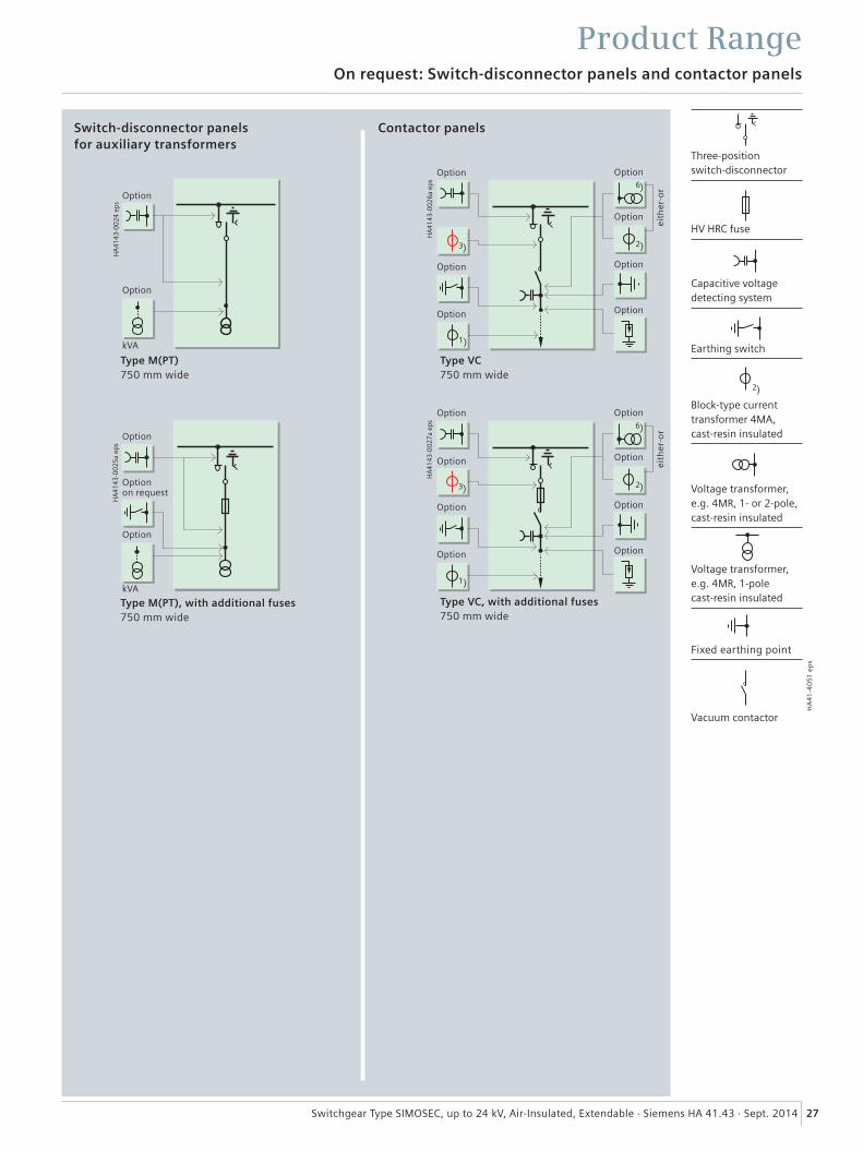
���
����
����
����
���
����
����
����
�
��
��
��
��
���
����
����
����
�
��
��
��
��
��
HA
41-4
051
ep
s
On request: Switch-disconnector panels and contactor panels
Product Range
27Switchgear Type SIMOSEC, up to 24 kV, Air-Insulated, Extendable · Siemens HA 41.43 · Sept. 2014
Switch-disconnector panels for auxiliary transformers
Contactor panels
Type M(PT)750 mm wide
Type VC 750 mm wide
Type VC, with additional fuses 750 mm wide
Three-position switch-disconnector
HV HRC fuse
Capacitive voltage detecting system
Earthing switch
Block-type current transformer 4MA, cast-resin insulated
Voltage transformer, e.g. 4MR, 1- or 2-pole, cast-resin insulated
Voltage transformer, e.g. 4MR, 1-pole cast-resin insulated
Vacuum contactor
Fixed earthing point
Option
Option
Option
Option
Option
Option
Option
Option
Option
Option
Option
Option
Option
Option
Option
Option
Option
kVA
���
����
����
����
�
Type M(PT), with additional fuses 750 mm wide
Option
Option
Option on request
kVA
eith
er-o
rei
ther
-or
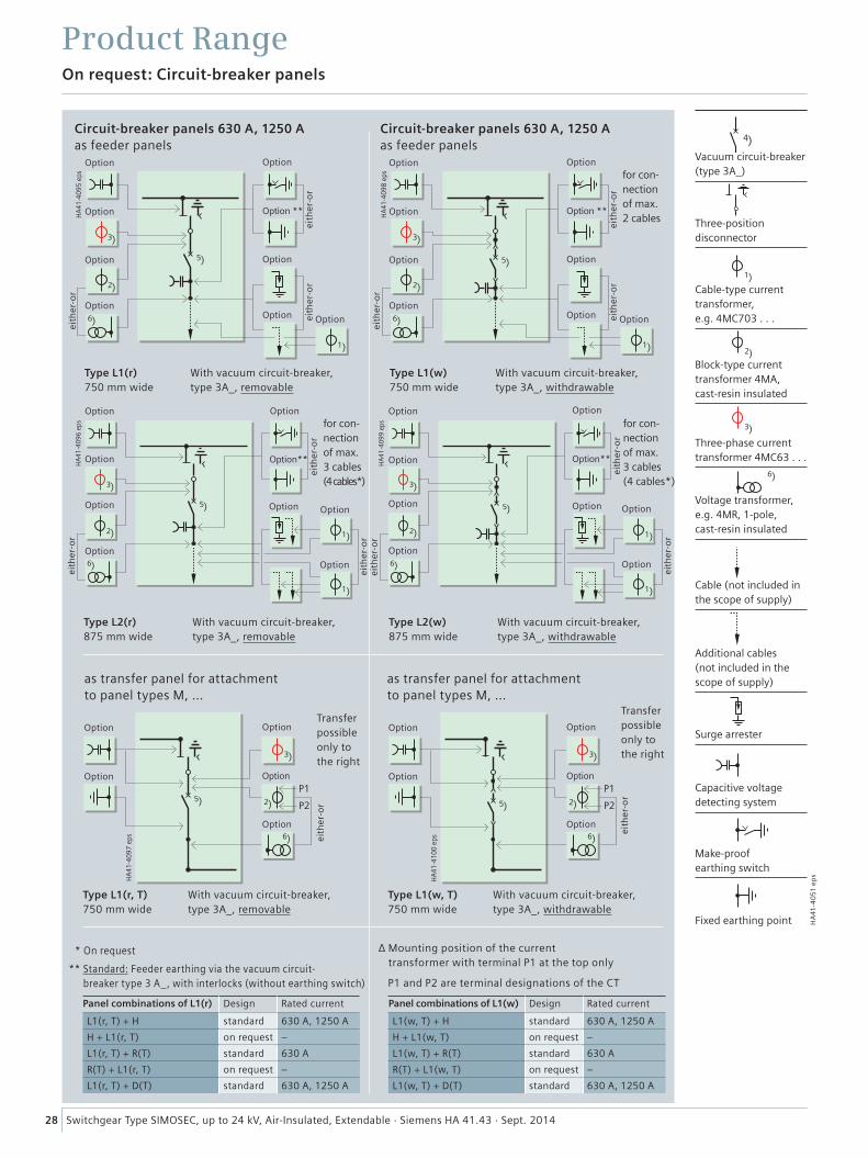
28 Switchgear Type SIMOSEC, up to 24 kV, Air-Insulated, Extendable · Siemens HA 41.43 · Sept. 2014
On request: Circuit-breaker panels
Product Range
Circuit-breaker panels 630 A, 1250 A as feeder panels
as transfer panel for attachment to panel types M, ...
Circuit-breaker panels 630 A, 1250 A as feeder panels
as transfer panel for attachment to panel types M, ...
Type L1(r)750 mm wide
Type L1(w)750 mm wide
Type L1(r, T)750 mm wide
Type L1(w, T)750 mm wide
With vacuum circuit-breaker, type 3A_, removable
With vacuum circuit-breaker, type 3A_, withdrawable
With vacuum circuit-breaker, type 3A_, removable
With vacuum circuit-breaker, type 3A_, withdrawable
��
��
��
��
��
���
����
������
��
��
��
��
��
���
����
������
��
��
��
�� ��
��
���
����
������
����
��
��
��
��
���
����
������
��
��
�� ��
��
���
����
������
��
��
��
��
��
��
��
���
����
������
Panel combinations of L1(r) Design Rated current
L1(r, T) + H standard 630 A, 1250 A
H + L1(r, T) on request –
L1(r, T) + R(T) standard 630 A
R(T) + L1(r, T) on request –
L1(r, T) + D(T) standard 630 A, 1250 A
Panel combinations of L1(w) Design Rated current
L1(w, T) + H standard 630 A, 1250 A
H + L1(w, T) on request –
L1(w, T) + R(T) standard 630 A
R(T) + L1(w, T) on request –
L1(w, T) + D(T) standard 630 A, 1250 A
4
��
��
��
��
HA
41-4
051
ep
s
Vacuum circuit-breaker (type 3A_)
Three-position disconnector
Cable-type current transformer, e.g. 4MC703 . . .
Block-type current transformer 4MA, cast-resin insulated
Three-phase current transformer 4MC63 . . .
Voltage transformer, e.g. 4MR, 1-pole, cast-resin insulated
Cable (not included in the scope of supply)
Additional cables (not included in the scope of supply)
Surge arrester
Capacitive voltage detecting system
Make-proof earthing switch
Fixed earthing point
* On request
** Standard: Feeder earthing via the vacuum circuit- breaker type 3 A_, with interlocks (without earthing switch)
∆ Mounting position of the current transformer with terminal P1 at the top only
P1 and P2 are terminal designations of the CT
eith
er-o
r
eith
er-o
r
eith
er-o
rei
ther
-or
eith
er-o
r
eith
er-o
rei
ther
-or
eith
er-o
r
eith
er-o
rei
ther
-or
eith
er-o
r
eith
er-o
r
eith
er-o
r
eith
er-o
r
Option
Option Option
OptionOption OptionOption
Option Option
Option Option
Option
Option
Option Option
OptionOption
Option
Option Option
Option
Option
Option
Option
Option Option
Option
OptionOption **
Option**
Option Option
Option**
Option **
Option
Option
Option Option
Option
OptionOption
Option
Option Option
Option
Optionfor con-nection of max. 2 cables
for con-nection of max. 3 cables (4 cables*)
Transfer possible only to the right
Transfer possible only to the right
for con-nection of max. 3 cables (4 cables*)
Type L2(r)875 mm wide
Type L2(w)875 mm wide
With vacuum circuit-breaker, type 3A_, removable
With vacuum circuit-breaker, type 3A_, withdrawable
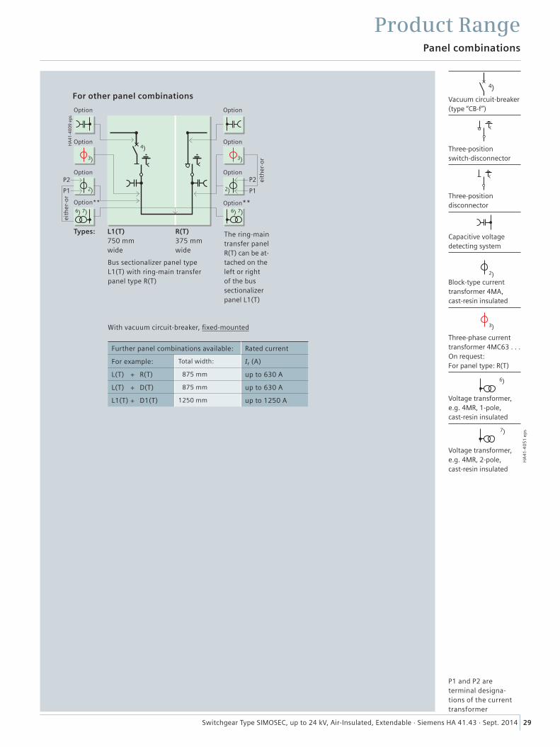
Panel combinations
Product Range
29Switchgear Type SIMOSEC, up to 24 kV, Air-Insulated, Extendable · Siemens HA 41.43 · Sept. 2014
���
����
������
����
��
��
��
��
��
�� ��
����������
For other panel combinations
L1(T) 750 mm wide
R(T) 375 mm wide
The ring-main transfer panel R(T) can be at-tached on the left or right of the bus sectio nalizer panel L1(T)
Bus sectionalizer panel type L1(T) with ring-main transfer panel type R(T)
With vacuum circuit-breaker, fixed-mounted
eith
er-o
r
eith
er-o
r
Option Option
Option Option
Option Option
Option** Option**
4
��
��
��
��
HA
41-4
051
ep
s
Vacuum circuit-breaker (type “CB-f”)
Three-position switch-disconnector
Three-position disconnector
Capacitive voltage detecting system
Block-type current transformer 4MA, cast-resin insulated
Three-phase current transformer 4MC63 . . . On request: For panel type: R(T)
Voltage transformer, e.g. 4MR, 1-pole, cast-resin insulated
Voltage transformer, e.g. 4MR, 2-pole, cast-resin insulated
P1 and P2 are terminal designa-tions of the current transformer
Further panel combinations available: Rated current
For example: Total width: Ir (A)
L(T) + R(T) 875 mm up to 630 A
L(T) + D(T) 875 mm up to 630 A
L1(T) + D1(T) 1250 mm up to 1250 A
Types:
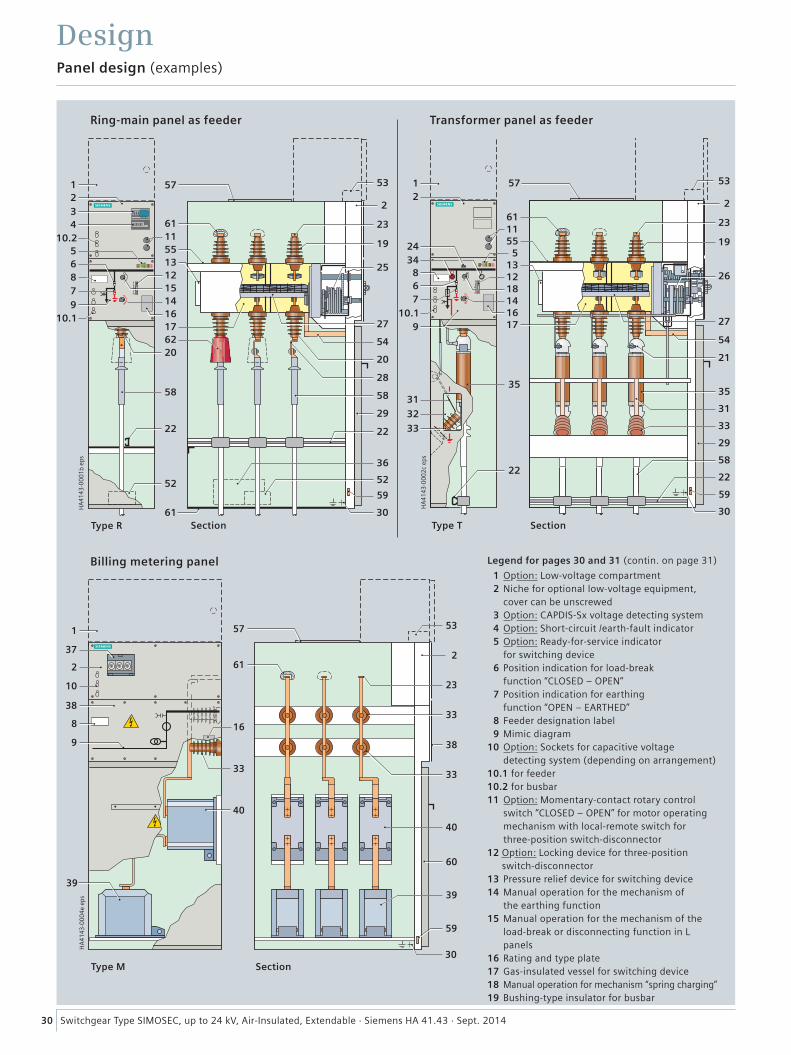
59 59
59
30 Switchgear Type SIMOSEC, up to 24 kV, Air-Insulated, Extendable · Siemens HA 41.43 · Sept. 2014
Legend for pages 30 and 31 (contin. on page 31)
1 Option: Low-voltage compartment 2 Niche for optional low-voltage equipment, cover can be unscrewed 3 Option: CAPDIS-Sx voltage detecting system 4 Option: Short-circuit /earth-fault indicator 5 Option: Ready-for-service indicator for switching device 6 Position indication for load-break function “CLOSED – OPEN” 7 Position indication for earthing function “OPEN – EARTHED” 8 Feeder designation label 9 Mimic diagram 10 Option: Sockets for capacitive voltage detecting system (depending on arrangement) 10.1 for feeder 10.2 for busbar 11 Option: Momentary-contact rotary control switch “CLOSED – OPEN” for motor operating mechanism with local-remote switch for three-position switch-disconnector12 Option: Locking device for three-position
switch-disconnector 13 Pressure relief device for switching device 14 Manual operation for the mechanism of the earthing function 15 Manual operation for the mechanism of the
load-break or disconnecting function in L panels
16 Rating and type plate 17 Gas-insulated vessel for switching device 18 Manual operation for mechanism “spring charging” 19 Bushing-type insulator for busbar
Panel design (examples)
Design
Ring-main panel as feeder Transformer panel as feeder
Billing metering panel
Type R Section Type T Section
Type M Section
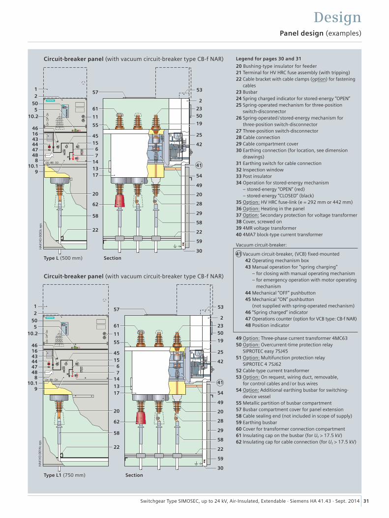
Panel design (examples)
Design
Circuit-breaker panel (with vacuum circuit-breaker type CB-f NAR)
Circuit-breaker panel (with vacuum circuit-breaker type CB-f NAR)
Type L (500 mm)
Type L1 (750 mm)
Section
Section
Legend for pages 30 and 31
20 Bushing-type insulator for feeder21 Terminal for HV HRC fuse assembly (with tripping)22 Cable bracket with cable clamps (option) for fastening
cables23 Busbar24 Spring charged indicator for stored-energy “OPEN”25 Spring-operated mechanism for three-position
switch-disconnector26 Spring-operated / stored-energy mechanism for
three-position switch-disconnector27 Three-position switch-disconnector28 Cable connection29 Cable compartment cover30 Earthing connection (for location, see dimension
drawings)31 Earthing switch for cable connection32 Inspection window33 Post insulator34 Operation for stored-energy mechanism
– stored-energy “OPEN” (red) – stored-energy “CLOSED” (black)
35 Option: HV HRC fuse-link (e = 292 mm or 442 mm)36 Option: Heating in the panel37 Option: Secondary protection for voltage transformer38 Cover, screwed on39 4MR voltage transformer40 4MA7 block-type current transformer
Vacuum circuit-breaker:
41 Vacuum circuit-breaker, (VCB) fixed-mounted42 Operating mechanism box43 Manual operation for "spring charging"
– for closing with manual operating mechanism – for emergency operation with motor operating mechanism
44 Mechanical “OFF” pushbutton45 Mechanical “ON” pushbutton
(not supplied with spring-operated mechanism)46 “Spring charged” indicator47 Operations counter (option for VCB type: CB-f NAR)48 Position indicator
49 Option: Three-phase current transformer 4MC6350 Option: Overcurrent-time protection relay
SIPROTEC easy 7SJ4551 Option: Multifunction protection relay
SIPROTEC 4 7SJ62 52 Cable-type current transformer53 Option: On request, wiring duct, removable,
for control cables and / or bus wires54 Option: Additional earthing busbar for switching-
device vessel55 Metallic partition of busbar compartment57 Busbar compartment cover for panel extension58 Cable sealing end (not included in scope of supply) 59 Earthing busbar 60 Cover for transformer connection compartment61 Insulating cap on the busbar (for Ur > 17.5 kV)62 Insulating cap for cable connection (for Ur > 17.5 kV)
59
59
31Switchgear Type SIMOSEC, up to 24 kV, Air-Insulated, Extendable · Siemens HA 41.43 · Sept. 2014
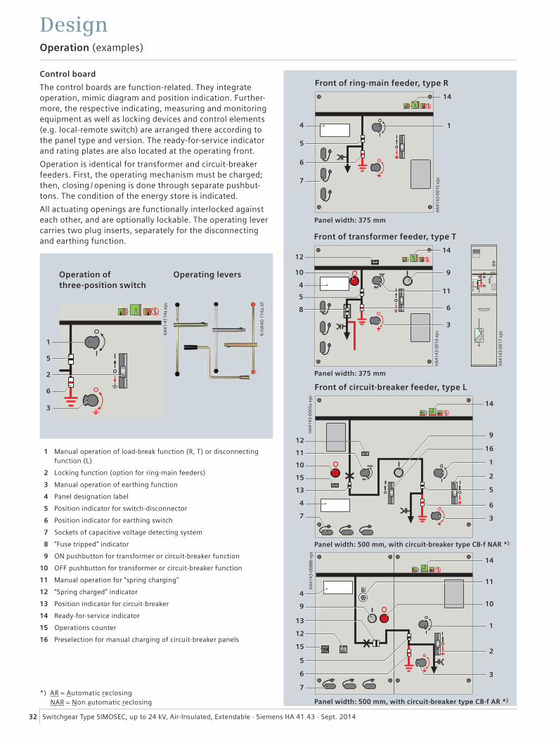
���
����
����
����
�
��
�
�
�
��
��
��
�
�
32 Switchgear Type SIMOSEC, up to 24 kV, Air-Insulated, Extendable · Siemens HA 41.43 · Sept. 2014
Operation (examples)
Design
Control board
The control boards are function-related. They integrate operation, mimic diagram and position indication. Further-more, the respective indicating, measuring and monitoring equipment as well as locking devices and control elements (e.g. local-remote switch) are arranged there according to the panel type and version. The ready-for-service indicator and rating plates are also located at the operating front.
Operation is identical for transformer and circuit-breaker feeders. First, the operating mechanism must be charged; then, closing / opening is done through separate pushbut-tons. The condition of the energy store is indicated.
All actuating openings are functionally interlocked against each other, and are optionally lockable. The operating lever carries two plug inserts, separately for the disconnecting and earthing function.
1 Manual operation of load-break function (R, T) or disconnecting function (L)
2 Locking function (option for ring-main feeders)
3 Manual operation of earthing function
4 Panel designation label
5 Position indicator for switch-disconnector
6 Position indicator for earthing switch
7 Sockets of capacitive voltage detecting system
8 “Fuse tripped” indicator
9 ON pushbutton for transformer or circuit-breaker function
10 OFF pushbutton for transformer or circuit-breaker function
11 Manual operation for "spring charging"
12 “Spring charged” indicator
13 Position indicator for circuit-breaker
14 Ready-for-service indicator
15 Operations counter
16 Preselection for manual charging of circuit-breaker panels
���
����
����
����
�
�
�
�
��
�
���
����
����
����
�
�� ��
��
��
��
��
�
�
�
�
�
�
�
���
���
����
����
����
�
��
��
����
��
�
�
�
��
�
�
�
��
Front of ring-main feeder, type R
Front of transformer feeder, type T
Front of circuit-breaker feeder, type L
���
����
������
�
�
�
�
�
�
Operation of three-position switch
Operating levers
R-H
A4
0-1
14a.
tif
Panel width: 375 mm
Panel width: 375 mm
Panel width: 500 mm, with circuit-breaker type CB-f NAR *)
Panel width: 500 mm, with circuit-breaker type CB-f AR *)
���
����
����
����
*) AR = Automatic reclosing NAR = Non automatic reclosing
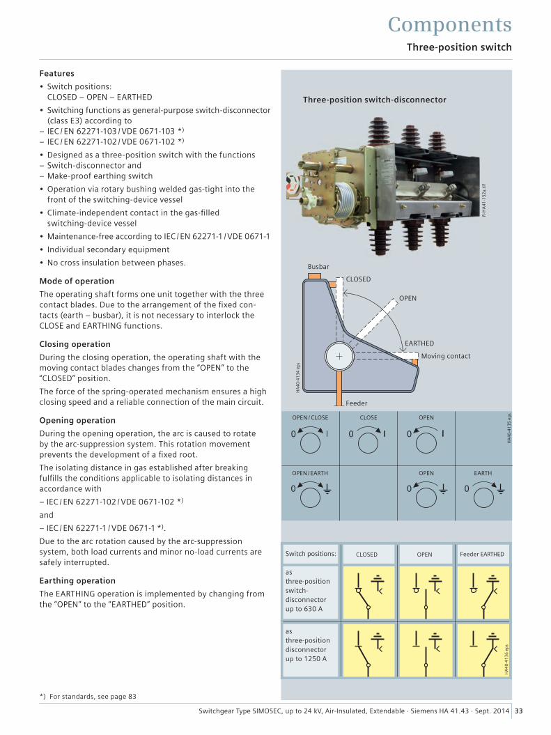
���
����
������
���
����
������
���
����
������
R-H
A41
-13
2a.
tif
33Switchgear Type SIMOSEC, up to 24 kV, Air-Insulated, Extendable · Siemens HA 41.43 · Sept. 2014
Three-position switch
Components
Three-position switch-disconnector
Features
• Switch positions: CLOSED – OPEN – EARTHED
• Switching functions as general-purpose switch-disconnector (class E3) according to
– IEC / EN 62271-103 / VDE 0671-103 *)
– IEC / EN 62271-102 / VDE 0671-102 *)
• Designed as a three-position switch with the functions – Switch-disconnector and – Make-proof earthing switch
• Operation via rotary bushing welded gas-tight into the front of the switching-device vessel
• Climate-independent contact in the gas-filled switching-device vessel
• Maintenance-free according to IEC / EN 62271-1 / VDE 0671-1
• Individual secondary equipment
• No cross insulation between phases.
Mode of operation
The operating shaft forms one unit together with the three contact blades. Due to the arrangement of the fixed con-tacts (earth – busbar), it is not necessary to interlock the CLOSE and EARTHING functions.
Closing operation
During the closing operation, the operating shaft with the moving contact blades changes from the “OPEN” to the “CLOSED” position.
The force of the spring-operated mechanism ensures a high closing speed and a reliable connection of the main circuit.
Opening operation
During the opening operation, the arc is caused to rotate by the arc-suppression system. This rotation movement prevents the development of a fixed root.
The isolating distance in gas established after breaking fulfills the conditions applicable to isolating distances in accordance with
– IEC / EN 62271-102 / VDE 0671-102 *)
and
– IEC / EN 62271-1 / VDE 0671-1 *).
Due to the arc rotation caused by the arc-suppression system, both load currents and minor no-load currents are safely interrupted.
Earthing operation
The EARTHING operation is implemented by changing from the “OPEN” to the “EARTHED” position.
Moving contact
EARTHED
OPEN
CLOSED
Busbar
Feeder
OPEN / CLOSE CLOSE OPEN
OPEN
CLOSED OPEN Feeder EARTHED
OPEN/EARTH EARTH
*) For standards, see page 83
Switch positions: as three-position switch- disconnector up to 630 A
asthree-position disconnector up to 1250 A
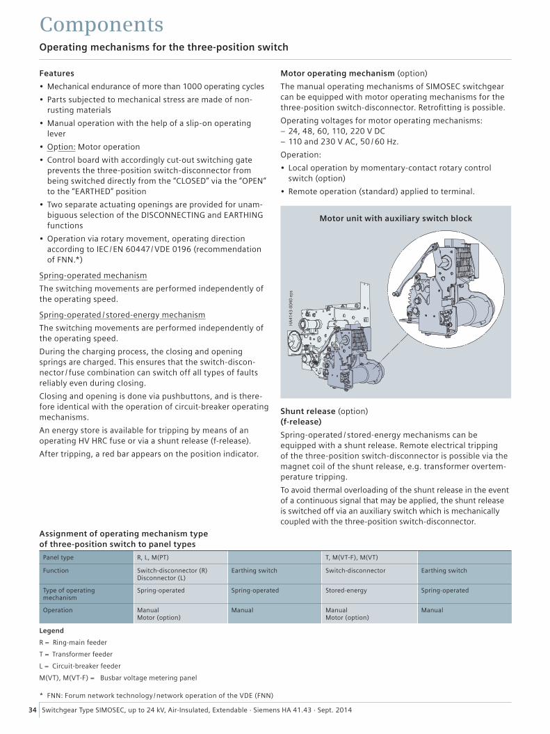
34 Switchgear Type SIMOSEC, up to 24 kV, Air-Insulated, Extendable · Siemens HA 41.43 · Sept. 2014
Operating mechanisms for the three-position switch
Components
Assignment of operating mechanism type of three-position switch to panel types
Panel type R, L, M(PT) T, M(VT-F), M(VT)
Function Switch-disconnector (R) Disconnector (L)
Earthing switch Switch-disconnector Earthing switch
Type of operating mechanism
Spring-operated Spring-operated Stored-energy Spring-operated
Operation Manual Motor (option)
Manual Manual Motor (option)
Manual
Features
• Mechanical endurance of more than 1000 operating cycles
• Parts subjected to mechanical stress are made of non-rusting materials
• Manual operation with the help of a slip-on operating lever
• Option: Motor operation
• Control board with accordingly cut-out switching gate prevents the three-position switch-disconnector from being switched directly from the “CLOSED” via the “OPEN” to the “EARTHED” position
• Two separate actuating openings are provided for unam-biguous selection of the DISCONNECTING and EARTHING functions
• Operation via rotary movement, operating direction according to IEC / EN 60447/ VDE 0196 (recommendation of FNN.*)
Spring-operated mechanism
The switching movements are performed independently of the operating speed.
Spring-operated / stored-energy mechanism
The switching movements are performed independently of the operating speed.
During the charging process, the closing and opening springs are charged. This ensures that the switch-discon-nector / fuse combination can switch off all types of faults reliably even during closing.
Closing and opening is done via pushbuttons, and is there-fore identical with the operation of circuit-breaker operating mechanisms.
An energy store is available for tripping by means of an operating HV HRC fuse or via a shunt release (f-release).
After tripping, a red bar appears on the position indicator.
Motor operating mechanism (option)
The manual operating mechanisms of SIMOSEC switchgear can be equipped with motor operating mechanisms for the three-position switch-disconnector. Retrofitting is possible.
Operating voltages for motor operating mechanisms: – 24, 48, 60, 110, 220 V DC – 110 and 230 V AC, 50 / 60 Hz.
Operation:
• Local operation by momentary-contact rotary control switch (option)
• Remote operation (standard) applied to terminal.
Shunt release (option) (f-release)
Spring-operated / stored-energy mechanisms can be equipped with a shunt release. Remote electrical tripping of the three-position switch-disconnector is possible via the magnet coil of the shunt release, e.g. transformer overtem-perature tripping.
To avoid thermal overloading of the shunt release in the event of a continuous signal that may be applied, the shunt release is switched off via an auxiliary switch which is mechanically coupled with the three-position switch-disconnector.
���
����
����
����
Motor unit with auxiliary switch block
* FNN: Forum network technology /network operation of the VDE (FNN)
Legend
R = Ring-main feeder
T = Transformer feeder
L = Circuit-breaker feeder
M(VT), M(VT-F) = Busbar voltage metering panel
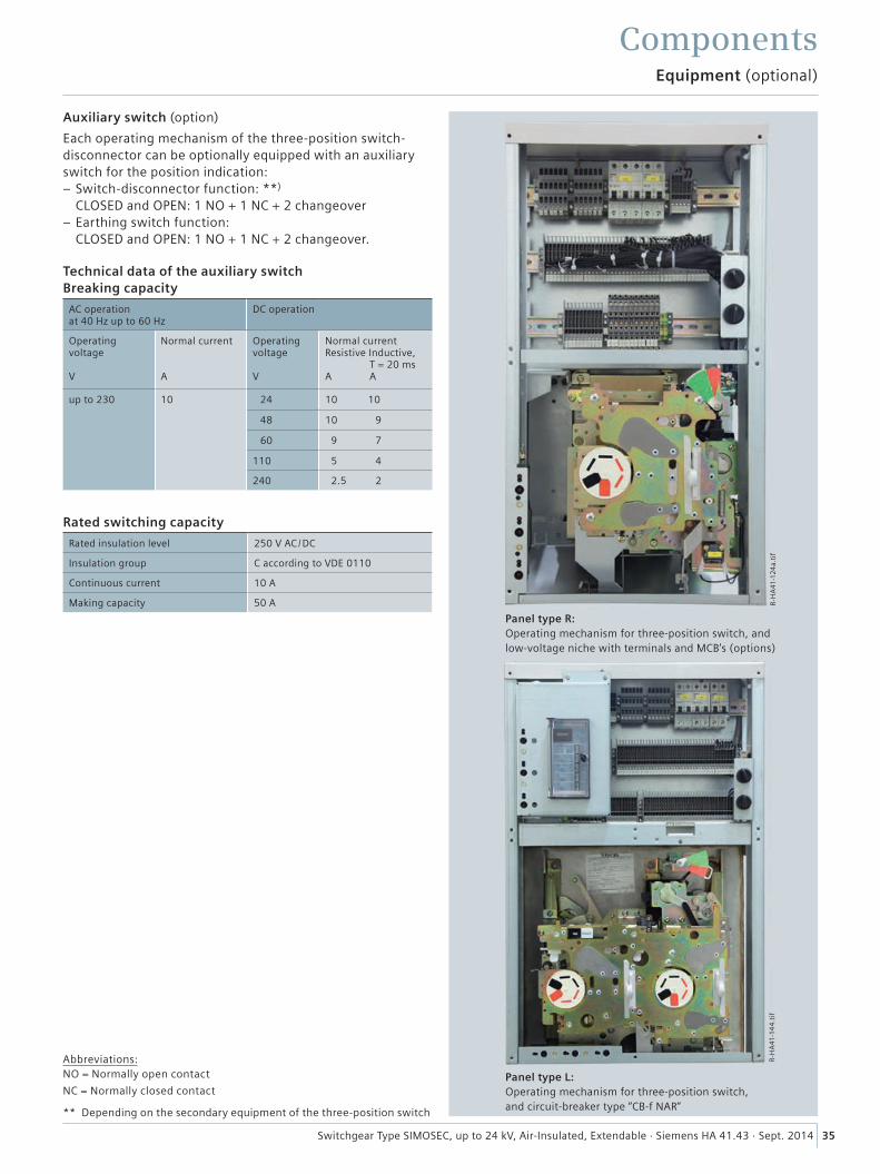
35Switchgear Type SIMOSEC, up to 24 kV, Air-Insulated, Extendable · Siemens HA 41.43 · Sept. 2014
Equipment (optional)
Components
Auxiliary switch (option)
Each operating mechanism of the three-position switch-disconnector can be optionally equipped with an auxiliary switch for the position indication:
– Switch-disconnector function: **) CLOSED and OPEN: 1 NO + 1 NC + 2 changeover
– Earthing switch function: CLOSED and OPEN: 1 NO + 1 NC + 2 changeover.
Technical data of the auxiliary switch Breaking capacity
AC operation at 40 Hz up to 60 Hz
DC operation
Operating voltage V
Normal current A
Operating voltage V
Normal current Resistive Inductive, T = 20 ms A A
up to 230 10 24 10 10
48 10 9
60 9 7
110 5 4
240 2.5 2
Rated switching capacity
Rated insulation level 250 V AC /DC
Insulation group C according to VDE 0110
Continuous current 10 A
Making capacity 50 A
Abbreviations: NO = Normally open contact
NC = Normally closed contact
R-H
A41
-124
a.ti
fR
-HA
41-1
44
.tif
Panel type R:Operating mechanism for three-position switch, and low-voltage niche with terminals and MCB's (options)
Panel type L:Operating mechanism for three-position switch, and circuit-breaker type “CB-f NAR“** Depending on the secondary equipment of the three-position switch
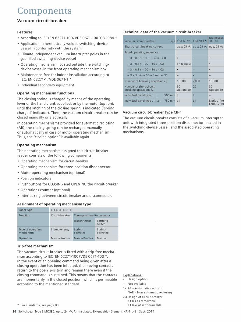
36 Switchgear Type SIMOSEC, up to 24 kV, Air-Insulated, Extendable · Siemens HA 41.43 · Sept. 2014
Vacuum circuit-breaker
Components
Technical data of the vacuum circuit-breaker
Vacuum circuit-breaker Type
CB-f AR *)
CB-f NAR *)
On request: 3AE )
Short-circuit breaking current up to 25 kA up to 25 kA up to 25 kA
Rated operating sequence:
– O – 0.3 s – CO – 3 min – CO • – –
– O – 0.3 s – CO – 15 s – CO on request – •
– O – 0.3 s – CO – 30 s – CO • – •
– O – 3 min – CO – 3 min – CO – • –
Number of breaking operations Ir 10000 2000 10000
Number of short-circuit breaking operations ISC
30 Option: 50
20 30 Option: 50
Individual panel type L ...: 500 mm L L –
Individual panel type L1 ...: 750 mm L1 L1 L1(r), L1(w) L2(r), L2(w)
Features
• According to IEC / EN 62271-100 / VDE 0671-100 / GB 1984 *
• Application in hermetically welded switching-device vessel in conformity with the system
• Climate-independent vacuum interrupter poles in the gas-filled switching-device vessel
• Operating mechanism located outside the switching- device vessel in the front operating mechanism box
• Maintenance-free for indoor installation according to IEC / EN 62271-1 / VDE 0671-1 *
• Individual secondary equipment.
Operating mechanism functions
The closing spring is charged by means of the operating lever or the hand crank supplied, or by the motor (option), until the latching of the closing spring is indicated (“spring charged” indicator). Then, the vacuum circuit-breaker can be closed manually or electrically.
In operating mechanisms provided for automatic reclosing (AR), the closing spring can be recharged manually or automatically in case of motor operating mechanism. Thus, the “closing option” is available again.
Operating mechanism
The operating mechanism assigned to a circuit-breaker feeder consists of the following components:
• Operating mechanism for circuit-breaker
• Operating mechanism for three-position disconnector
• Motor operating mechanism (optional)
• Position indicators
• Pushbuttons for CLOSING and OPENING the circuit-breaker
• Operations counter (optional)
• Interlocking between circuit-breaker and disconnector.
Trip-free mechanism
The vacuum circuit-breaker is fitted with a trip-free mecha-nism according to IEC / EN 62271-100 / VDE 0671-100 *. In the event of an opening command being given after a closing operation has been initiated, the moving contacts return to the open position and remain there even if the closing command is sustained. This means that the contacts are momentarily in the closed position, which is permissible according to the mentioned standard.
Vacuum circuit-breaker type CB-f
The vacuum circuit-breaker consists of a vacuum interrupter unit with integrated three-position disconnector located in the switching-device vessel, and the associated operating mechanisms.
Assignment of operating mechanism type
Panel type L, L1, L(T), L1(T)
Function Circuit-breaker Three-position disconnector
Disconnector Earthing switch
Type of operating mechanism
Stored-energy Spring- operated
Spring- operated
Operation Manual / motor Manual / motor Manual
* For standards, see page 83
Explanations: • Design option
– Not available
*) AR = Automatic reclosing NAR = Non automatic reclosing
) Design of circuit-breaker: • CB-r as removable • CB-w as withdrawable
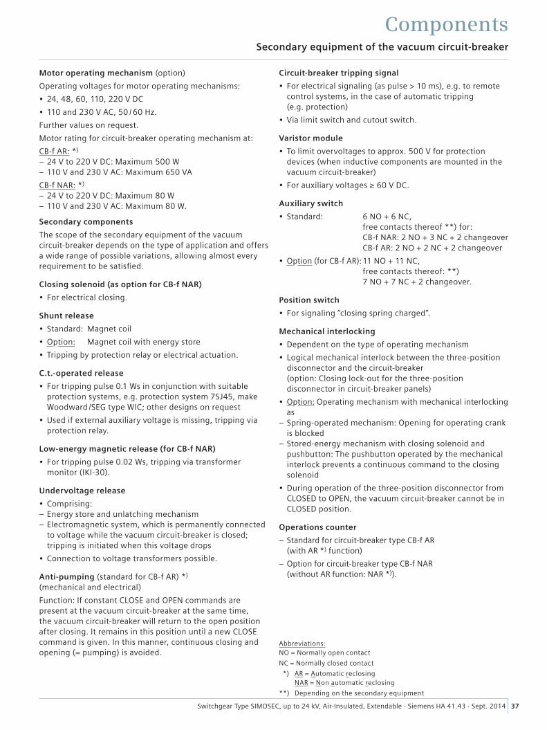
37Switchgear Type SIMOSEC, up to 24 kV, Air-Insulated, Extendable · Siemens HA 41.43 · Sept. 2014
Secondary equipment of the vacuum circuit-breaker
Components
Motor operating mechanism (option)
Operating voltages for motor operating mechanisms:
• 24, 48, 60, 110, 220 V DC
• 110 and 230 V AC, 50 / 60 Hz.
Further values on request.
Motor rating for circuit-breaker operating mechanism at:
CB-f AR: *)
– 24 V to 220 V DC: Maximum 500 W – 110 V and 230 V AC: Maximum 650 VA
CB-f NAR: *)
– 24 V to 220 V DC: Maximum 80 W – 110 V and 230 V AC: Maximum 80 W.
Secondary components
The scope of the secondary equipment of the vacuum circuit-breaker depends on the type of application and offers a wide range of possible variations, allowing almost every requirement to be satisfied.
Closing solenoid (as option for CB-f NAR)
• For electrical closing.
Shunt release
• Standard: Magnet coil
• Option: Magnet coil with energy store
• Tripping by protection relay or electrical actuation.
C.t.-operated release
• For tripping pulse 0.1 Ws in conjunction with suitable protection systems, e.g. protection system 7SJ45, make Woodward /SEG type WIC; other designs on request
• Used if external auxiliary voltage is missing, tripping via protection relay.
Low-energy magnetic release (for CB-f NAR)
• For tripping pulse 0.02 Ws, tripping via transformer monitor (IKI-30).
Undervoltage release
• Comprising: – Energy store and unlatching mechanism – Electromagnetic system, which is permanently connected to voltage while the vacuum circuit-breaker is closed; tripping is initiated when this voltage drops
• Connection to voltage transformers possible.
Anti-pumping (standard for CB-f AR) *) (mechanical and electrical)
Function: If constant CLOSE and OPEN commands are present at the vacuum circuit-breaker at the same time, the vacuum circuit-breaker will return to the open position after closing. It remains in this position until a new CLOSE command is given. In this manner, continuous closing and opening (= pumping) is avoided.
Circuit-breaker tripping signal
• For electrical signaling (as pulse > 10 ms), e.g. to remote control systems, in the case of automatic tripping (e.g. protection)
• Via limit switch and cutout switch.
Varistor module
• To limit overvoltages to approx. 500 V for protection devices (when inductive components are mounted in the vacuum circuit-breaker)
• For auxiliary voltages ≥ 60 V DC.
Auxiliary switch
• Standard: 6 NO + 6 NC, free contacts thereof **) for: CB-f NAR: 2 NO + 3 NC + 2 changeover CB-f AR: 2 NO + 2 NC + 2 changeover
• Option (for CB-f AR): 11 NO + 11 NC, free contacts thereof: **) 7 NO + 7 NC + 2 changeover.
Position switch
• For signaling “closing spring charged”.
Mechanical interlocking
• Dependent on the type of operating mechanism
• Logical mechanical interlock between the three-position disconnector and the circuit-breaker (option: Closing lock-out for the three-position disconnector in circuit-breaker panels)
• Option: Operating mechanism with mechanical interlocking as
– Spring-operated mechanism: Opening for operating crank is blocked
– Stored-energy mechanism with closing solenoid and pushbutton: The pushbutton operated by the mechanical interlock prevents a continuous command to the closing solenoid
• During operation of the three-position disconnector from CLOSED to OPEN, the vacuum circuit-breaker cannot be in CLOSED position.
Operations counter
– Standard for circuit-breaker type CB-f AR (with AR *) function)
– Option for circuit-breaker type CB-f NAR (without AR function: NAR *)).
Abbreviations: NO = Normally open contact
NC = Normally closed contact
*) AR = Automatic reclosing NAR = Non automatic reclosing
**) Depending on the secondary equipment
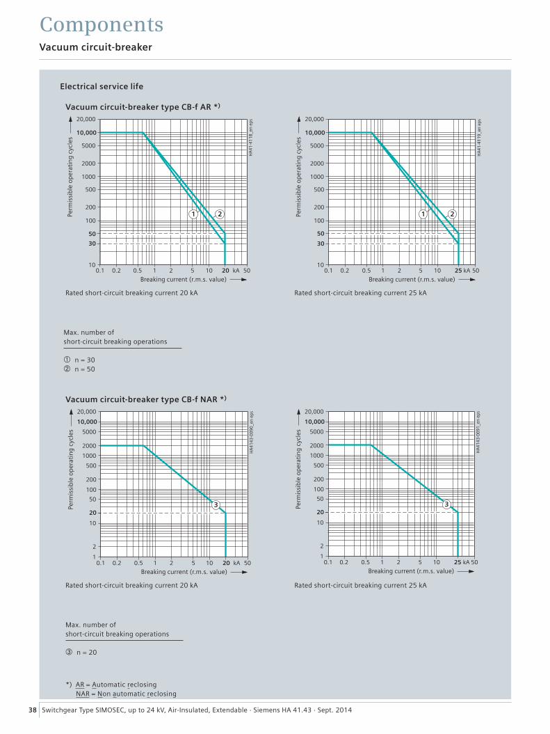
38 Switchgear Type SIMOSEC, up to 24 kV, Air-Insulated, Extendable · Siemens HA 41.43 · Sept. 2014
Vacuum circuit-breaker
Components
����
������
����
����
����
������
���� ����������������������
����
���
��
���
������
������ � � ����
����
���
������
���
����
��
�� �
���
����
����
����
�
��
���
����
����
����
���
����
���� �
����
��
����
������
����������������������������
����
���
��
�
���
������
��
����� � � �����
��
����
����
������
���
����
�
��� �
�
����
������
����
����
����
������
���� ����������������������
����
���
��
���
������
������ � � ����
����
���
������
���
����
��
�� �
���
����
����
����
�
��
���
����
����
����
���
����
���� �
����
��
����
������
����������������������������
����
���
��
�
���
������
��
����� � � �����
��
����
����
������
���
����
�
��� �
�
Electrical service life
Vacuum circuit-breaker type CB-f AR *)
Vacuum circuit-breaker type CB-f NAR *)
Rated short-circuit breaking current 20 kA
Rated short-circuit breaking current 20 kA
Rated short-circuit breaking current 25 kA
Rated short-circuit breaking current 25 kA
Max. number of short-circuit breaking operations n = 30 n = 50
Max. number of short-circuit breaking operations n = 20
*) AR = Automatic reclosing NAR = Non automatic reclosing
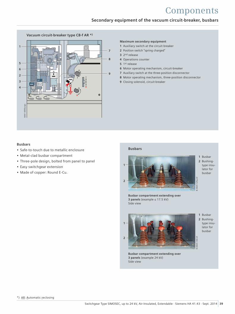
39Switchgear Type SIMOSEC, up to 24 kV, Air-Insulated, Extendable · Siemens HA 41.43 · Sept. 2014
Secondary equipment of the vacuum circuit-breaker, busbars
Components
Vacuum circuit-breaker type CB-f AR *)
Maximum secondary equipment
1 Auxiliary switch at the circuit-breaker
2 Position switch “spring charged”
3 2nd release
4 Operations counter
5 1st release
6 Motor operating mechanism, circuit-breaker
7 Auxiliary switch at the three-position disconnector
8 Motor operating mechanism, three-position disconnector
9 Closing solenoid, circuit-breaker
Busbars
• Safe-to-touch due to metallic enclosure
• Metal-clad busbar compartment
• Three-pole design, bolted from panel to panel
• Easy switchgear extension
• Made of copper: Round E-Cu.
Busbars
R-H
A41
-12
5a.
tif
R-H
A41
-14
0.t
if
1
1
2
2
1 Busbar
2 Bushing-type insu-lator for busbar
1 Busbar
2 Bushing-type insu-lator for busbar
Busbar compartment extending over 3 panels (example ≤ 17.5 kV) Side view
Busbar compartment extending over 3 panels (example 24 kV) Side view
*) AR: Automatic reclosing
HA
41-4
093a
eps
7
9
3
2
5
4
8
1
6
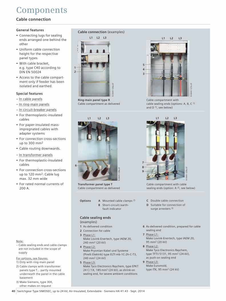
12
40 Switchgear Type SIMOSEC, up to 24 kV, Air-Insulated, Extendable · Siemens HA 41.43 · Sept. 2014
R-H
A41
-12
6a.
tif
R-H
A41
-12
7a.t
if
L1 L2 L3
5
4
3
L1 L2 L3
R-H
A41
-12
9a.
tif
R-H
A41
-12
8a.
tif
L1
6
L2 L3
7
8
9
L2 L3L1
ComponentsCable connection
General features
• Connecting lugs for sealing ends arranged one behind the other
• Uniform cable connection height for the respective panel types
• With cable bracket, e.g. type C40 according to DIN EN 50024
• Access to the cable compart-ment only if feeder has been isolated and earthed.
Special features
– In cable panels
– In ring-main panels
– In circuit-breaker panels
• For thermoplastic-insulated cables
• For paper-insulated mass- impregnated cables with adapter systems
• For connection cross-sections up to 300 mm2
• Cable routing downwards.
– In transformer panels
• For thermoplastic-insulated cables
• For connection cross-sections up to 120 mm2: Cable lug max. 32 mm wide
• For rated normal currents of 200 A.
Cable connection (examples)
Ring-main panel type RCable compartment as delivered
Cable compartment with cable sealing ends (options: A, B, C 1) and D 1), see below)
Transformer panel type TCable compartment as delivered
Cable compartment with cablesealing ends (option: A 2), see below)
A Mounted cable clamps 2)
B Short-circuit / earth- fault indicator
Options C Double cable connection
D Suitable for connection of surge arresters 3)
Cable sealing ends (examples)1 As-delivered condition
2 Connection for cable
3 Phase L1: Make Lovink-Enertech, type IAEM 20, 240 mm2 (20 kV)
4 Phase L2: Make Prysmian Kabel und Systeme (Pirelli Elektrik) type ELTI mb-1C-2h-C-T3, 240 mm2 (24 kV)
5 Phase L3: Make Tyco Electronics Raychem, type EPKT 24 C / 1X, 185 mm2 (24 kV), as shrink-on sealing end, for severe ambient conditions
6 As-delivered condition, prepared for cable sealing end
7 Phase L1: Make Lovink-Enertech, type IAEM 20, 95 mm2 (20 kV)
8 Phase L2: Make Tyco Electronics Raychem, type TFTI / 5131, 95 mm2 (24 kV), as push-on sealing end
9 Phase L3: Make Euromold, type ITK, 95 mm2 (24 kV)
For options, see figures: 1) Only with ring-main panel
2) Cable clamps with transformer panels type T... partly mounted underneath the panel in the cable basement
3) Make Siemens, type 3EK, other makes on request
Note: – Cable sealing ends and cable clamps
are not included in the scope of supply
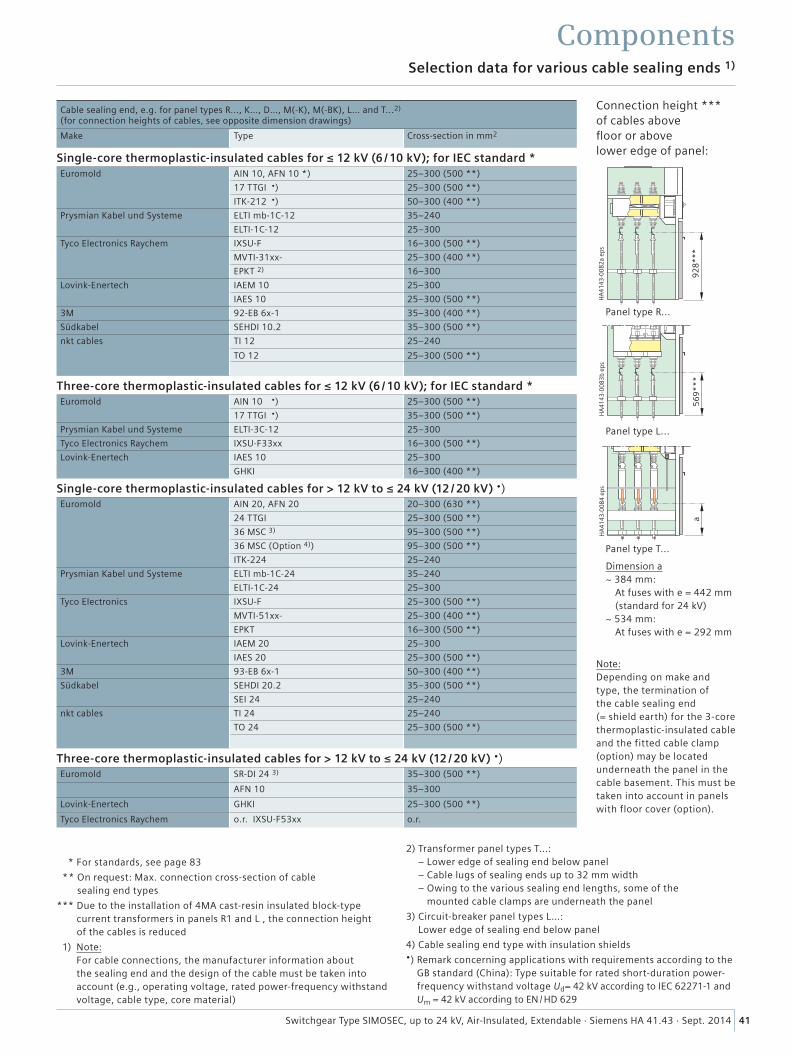
41Switchgear Type SIMOSEC, up to 24 kV, Air-Insulated, Extendable · Siemens HA 41.43 · Sept. 2014
����
��
���
����
����
����
�
�
���
����
����
����
* For standards, see page 83
** On request: Max. connection cross-section of cable sealing end types
*** Due to the installation of 4MA cast-resin insulated block-type current transformers in panels R1 and L , the connection height of the cables is reduced
1) Note: For cable connections, the manufacturer information about the sealing end and the design of the cable must be taken into account (e.g., operating voltage, rated power-frequency withstand voltage, cable type, core material)
2) Transformer panel types T...: – Lower edge of sealing end below panel – Cable lugs of sealing ends up to 32 mm width – Owing to the various sealing end lengths, some of the
mounted cable clamps are underneath the panel
3) Circuit-breaker panel types L…: Lower edge of sealing end below panel
4) Cable sealing end type with insulation shields•) Remark concerning applications with requirements according to the
GB standard (China): Type suitable for rated short-duration power-frequency withstand voltage Ud= 42 kV according to IEC 62271-1 and Um = 42 kV according to EN / HD 629
Connection height *** of cables above floor or above lower edge of panel:
Panel type R...
Panel type L...
Panel type T...
Dimension a ~ 384 mm: At fuses with e = 442 mm (standard for 24 kV)~ 534 mm: At fuses with e = 292 mm
Note: Depending on make and type, the termination of the cable sealing end (= shield earth) for the 3-core thermoplastic-insulated cable and the fitted cable clamp (option) may be located underneath the panel in the cable basement. This must be taken into account in panels with floor cover (option).
Selection data for various cable sealing ends 1)
Components
Cable sealing end, e.g. for panel types R..., K…, D…, M(-K), M(-BK), L… and T...2) (for connection heights of cables, see opposite dimension drawings)
Make Type Cross-section in mm2
Single-core thermoplastic-insulated cables for ≤ 12 kV (6 / 10 kV); for IEC standard *Euromold AIN 10, AFN 10 *) 25–300 (500 **)
17 TTGI •) 25–300 (500 **)
ITK-212 •) 50–300 (400 **)
Prysmian Kabel und Systeme ELTI mb-1C-12 35–240
ELTI-1C-12 25–300
Tyco Electronics Raychem IXSU-F 16–300 (500 **)
MVTI-31xx- 25–300 (400 **)
EPKT 2) 16–300
Lovink-Enertech IAEM 10 25–300
IAES 10 25–300 (500 **)
3M 92-EB 6x-1 35–300 (400 **)
Südkabel SEHDI 10.2 35–300 (500 **)
nkt cables TI 12 25–240
TO 12 25–300 (500 **)
Three-core thermoplastic-insulated cables for ≤ 12 kV (6 / 10 kV); for IEC standard *Euromold AIN 10 •) 25–300 (500 **)
17 TTGI •) 35–300 (500 **)
Prysmian Kabel und Systeme ELTI-3C-12 25–300
Tyco Electronics Raychem IXSU-F33xx 16–300 (500 **)
Lovink-Enertech IAES 10 25–300
GHKI 16–300 (400 **)
Single-core thermoplastic-insulated cables for > 12 kV to ≤ 24 kV (12 / 20 kV) •)Euromold AIN 20, AFN 20 20–300 (630 **)
24 TTGI 25–300 (500 **)
36 MSC 3) 95–300 (500 **)
36 MSC (Option 4)) 95–300 (500 **)
ITK-224 25–240
Prysmian Kabel und Systeme ELTI mb-1C-24 35–240
ELTI-1C-24 25–300
Tyco Electronics IXSU-F 25–300 (500 **)
MVTI-51xx- 25–300 (400 **)
EPKT 16–300 (500 **)
Lovink-Enertech IAEM 20 25–300
IAES 20 25–300 (500 **)
3M 93-EB 6x-1 50–300 (400 **)
Südkabel SEHDI 20.2 35–300 (500 **)
SEI 24 25–240
nkt cables TI 24 25–240
TO 24 25–300 (500 **)
Three-core thermoplastic-insulated cables for > 12 kV to ≤ 24 kV (12 / 20 kV) •)Euromold SR-DI 24 3) 35–300 (500 **)
AFN 10 35–300
Lovink-Enertech GHKI 25–300 (500 **)
Tyco Electronics Raychem o.r. IXSU-F53xx o.r.
���
����
����
����
�
����
��
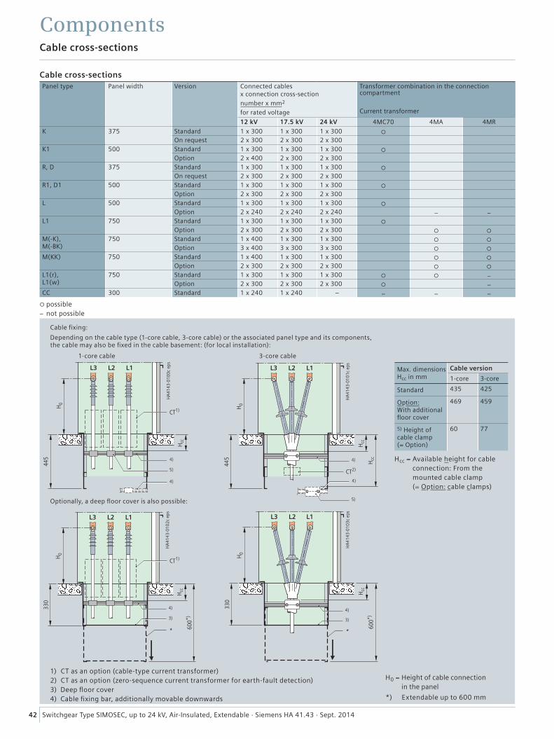
possible – not possible
42 Switchgear Type SIMOSEC, up to 24 kV, Air-Insulated, Extendable · Siemens HA 41.43 · Sept. 2014
Cable cross-sections
Components
Cable cross-sectionsPanel type Panel width Version Connected cables
x connection cross-sectionnumber x mm2
for rated voltage
Transformer combination in the connection compartment
Current transformer
12 kV 17.5 kV 24 kV 4MC70 4MA 4MR
K 375 Standard 1 x 300 1 x 300 1 x 300
On request 2 x 300 2 x 300 2 x 300K1 500 Standard 1 x 300 1 x 300 1 x 300
Option 2 x 400 2 x 300 2 x 300R, D 375 Standard 1 x 300 1 x 300 1 x 300
On request 2 x 300 2 x 300 2 x 300R1, D1 500 Standard 1 x 300 1 x 300 1 x 300
Option 2 x 300 2 x 300 2 x 300L 500 Standard 1 x 300 1 x 300 1 x 300
Option 2 x 240 2 x 240 2 x 240 – –L1 750 Standard 1 x 300 1 x 300 1 x 300
Option 2 x 300 2 x 300 2 x 300
M(-K), M(-BK)
750 Standard 1 x 400 1 x 300 1 x 300
Option 3 x 400 3 x 300 3 x 300
M(KK) 750 Standard 1 x 400 1 x 300 1 x 300
Option 2 x 300 2 x 300 2 x 300
L1(r), L1(w)
750 Standard 1 x 300 1 x 300 1 x 300 –Option 2 x 300 2 x 300 2 x 300 –
CC 300 Standard 1 x 240 1 x 240 – – – –
Cable fixing:
Depending on the cable type (1-core cable, 3-core cable) or the associated panel type and its components, the cable may also be fixed in the cable basement: (for local installation):
1-core cable
Optionally, a deep floor cover is also possible:
1) CT as an option (cable-type current transformer)2) CT as an option (zero-sequence current transformer for earth-fault detection)3) Deep floor cover4) Cable fixing bar, additionally movable downwards
H0 = Height of cable connection in the panel
*) Extendable up to 600 mm
Hcc = Available height for cable connection: From the mounted cable clamp (= Option: cable clamps)
3-core cable
Max. dimensions Hcc in mm
Cable version
1-core 3-core
Standard 435 425
Option: With additional floor cover
469 459
5) Height of cable clamp (= Option)
60 77
���
�� �� ��
���
����
����
����
�
��
���
����
��
��
��
�� �� ��
����
�
���
����
����
����
�
���
����
�
��
��
���
��
���
�� �� ��
����
���
����
����
����
�
��
���
���
��
��
��
�� �� ��
���
����
����
����
�
����
�
���
�
��
��
���
��
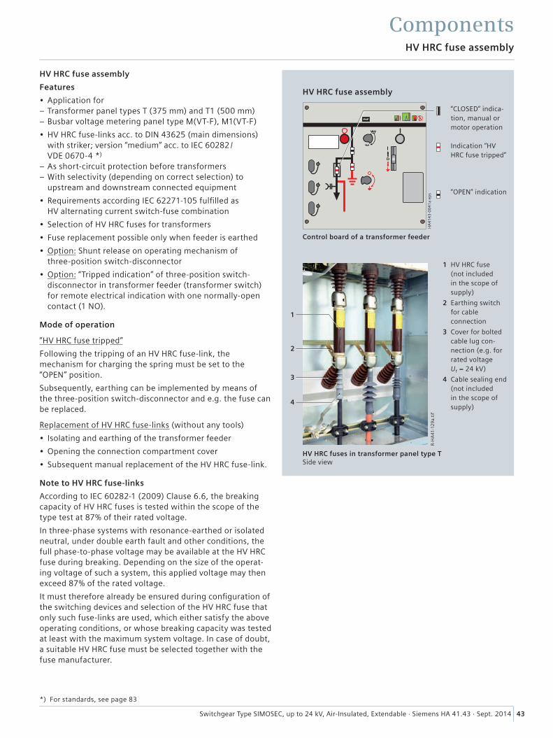
1
2
3
4
R-H
A41
-12
9a.
tif
HA
41
43
-00
41
a ep
s
43Switchgear Type SIMOSEC, up to 24 kV, Air-Insulated, Extendable · Siemens HA 41.43 · Sept. 2014
HV HRC fuse assembly
Features
• Application for – Transformer panel types T (375 mm) and T1 (500 mm) – Busbar voltage metering panel type M(VT-F), M1(VT-F)
• HV HRC fuse-links acc. to DIN 43625 (main dimensions) with striker; version “medium” acc. to IEC 60282 / VDE 0670-4 *)
– As short-circuit protection before transformers – With selectivity (depending on correct selection) to upstream and downstream connected equipment
• Requirements according IEC 62271-105 fulfilled as HV alternating current switch-fuse combination
• Selection of HV HRC fuses for transformers
• Fuse replacement possible only when feeder is earthed
• Option: Shunt release on operating mechanism of three-position switch-disconnector
• Option: “Tripped indication” of three-position switch-disconnector in transformer feeder (transformer switch) for remote electrical indication with one normally-open contact (1 NO).
Mode of operation
“HV HRC fuse tripped”
Following the tripping of an HV HRC fuse-link, the mechanism for charging the spring must be set to the “OPEN” position.
Subsequently, earthing can be implemented by means of the three-position switch-disconnector and e.g. the fuse can be replaced.
Replacement of HV HRC fuse-links (without any tools)
• Isolating and earthing of the transformer feeder
• Opening the connection compartment cover
• Subsequent manual replacement of the HV HRC fuse-link.
Note to HV HRC fuse-links
According to IEC 60282-1 (2009) Clause 6.6, the breaking capacity of HV HRC fuses is tested within the scope of the type test at 87% of their rated voltage.
In three-phase systems with resonance-earthed or isolated neutral, under double earth fault and other conditions, the full phase-to-phase voltage may be available at the HV HRC fuse during breaking. Depending on the size of the operat-ing voltage of such a system, this applied voltage may then exceed 87% of the rated voltage.
It must therefore already be ensured during configuration of the switching devices and selection of the HV HRC fuse that only such fuse-links are used, which either satisfy the above operating conditions, or whose breaking capacity was tested at least with the maximum system voltage. In case of doubt, a suitable HV HRC fuse must be selected together with the fuse manufacturer.
HV HRC fuse assembly
“CLOSED” indica-tion, manual or motor operation
Indication “HV HRC fuse tripped”
“OPEN” indication
1 HV HRC fuse (not included in the scope of supply)
2 Earthing switch for cable connection
3 Cover for bolted cable lug con-nection (e.g. for rated voltage Ur = 24 kV)
4 Cable sealing end (not included in the scope of supply)
Control board of a transformer feeder
HV HRC fuses in transformer panel type T Side view
*) For standards, see page 83
HV HRC fuse assembly
Components
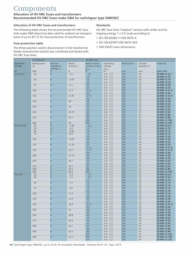
44 Switchgear Type SIMOSEC, up to 24 kV, Air-Insulated, Extendable · Siemens HA 41.43 · Sept. 2014
ComponentsAllocation of HV HRC fuses and transformersRecommended HV HRC fuses make SIBA for switchgear type SIMOSEC
Operating voltage kV
Transformer HV HRC fuse
Rated power SN kVA
Relativeimpedance voltage uk %
Rated current I1 A
Rated normal current of fuse Ifuse A
Operating voltage Ufuse kV
Dimension e mm
Outside diameter d mm
Order No. Make SIBA
3.3 to 3.6 20 4 3.5 6.3 3 to 7.2 292 53 30 098 13.6,3 10 3 to 7.2 292 53 30 098 13.10
50 4 8.75 16 3 to 7.2 292 53 30 098 13.16 20 3 to 7.2 292 53 30 098 13.20
75 4 13.1 20 3 to 7.2 292 53 30 098 13.20 25 3 to 7.2 292 53 30 098 13.25
100 4 17.5 31.5 3 to 7.2 292 53 30 098 13.31,5 40 3 to 7.2 292 53 30 098 13.40
125 4 21.87 31.5 3 to 7.2 292 53 30 098 13.31,5 40 3 to 7.2 292 53 30 098 13.40
160 4 28 40 3 to 7.2 292 53 30 098 13.40 50 3 to 7.2 292 53 30 098 13.50
200 4 35 50 3 to 7.2 292 53 30 098 13.50 63 3 to 7.2 292 67 30 099 13.63
250 4 43.74 63 3 to 7.2 292 67 30 099 13.63 80 3 to 7.2 292 67 30 099 13.80
315 4 55.1 80 3 to 7.2 292 67 30 099 13.80100 3 to 7.2 292 67 30 099 13.100
400 4 70 100 3 to 7.2 292 67 30 099 13.1004.16 to 4.8 20 4 2.78 6.3 3 to 7.2 292 53 30 098 13.6,3
30 4 4.2 10 3 to 7.2 292 53 30 098 13.1050 4 6.93 16 3 to 7.2 292 53 30 098 13.1675 4 10.4 16 3 to 7.2 292 53 30 098 13.16
20 3 to 7.2 292 53 30 098 13.20100 4 13.87 20 3 to 7.2 292 53 30 098 13.20
25 3 to 7.2 292 53 30 098 13.25125 4 17.35 25 3 to 7.2 292 53 30 098 13.25
31.5 3 to 7.2 292 53 30 098 13.31,5160 4 22.2 31.5 3 to 7.2 292 53 30 098 13.31,5
40 3 to 7.2 292 53 30 098 13.40200 4 27.75 40 3 to 7.2 292 53 30 098 13.40
50 3 to 7.2 292 53 30 098 13.50250 4 34.7 50 3 to 7.2 292 53 30 098 13.50
63 3 to 7.2 292 67 30 099 13.63315 4 43.7 63 3 to 7.2 292 67 30 099 13.63400 4 55.5 80 3 to 7.2 292 67 30 099 13.80500 4 69.4 100 3 to 7.2 292 67 30 099 13.100
5 to 5.5 20 4 2.3 6.3 3 to 7.2 292 53 30 098 13.6,330 4 3.2 6.3 3 to 7.2 292 53 30 098 13.6,3
10 3 to 7.2 292 53 30 098 13.1050 4 5.7 10 3 to 7.2 292 53 30 098 13.10
16 3 to 7.2 292 53 30 098 13.1675 4 8.6 16 3 to 7.2 292 53 30 098 13.16
20 3 to 7.2 292 53 30 098 13.20100 4 11.5 16 3 to 7.2 292 53 30 098 13.16
20 3 to 7.2 292 53 30 098 13.20125 4 14.4 20 3 to 7.2 292 53 30 098 13.20
25 3 to 7.2 292 53 30 098 13.25160 4 18.4 31.5 3 to 7.2 292 53 30 098 13.31,5
40 3 to 7.2 292 53 30 098 13.40200 4 23 40 3 to 7.2 292 53 30 098 13.40
50 3 to 7.2 292 53 30 098 13.50250 4 28.8 40 3 to 7.2 292 53 30 098 13.40
50 3 to 7.2 292 53 30 098 13.50315 4 36.3 50 3 to 7.2 292 53 30 098 13.50
63 3 to 7.2 292 67 30 099 13.63400 4 46.1 63 3 to 7.2 292 67 30 099 13.63
80 3 to 7.2 292 67 30 099 13.80500 4 52.5 80 3 to 7.2 292 67 30 099 13.80
100 3 to 7.2 292 67 30 099 13.100630 4 72.7 100 3 to 7.2 292 67 30 099 13.100
125 3 to 7.2 292 67 30 099 13.125
Allocation of HV HRC fuses and transformers
The following table shows the recommended HV HRC fuse-links make SIBA (electrical data valid for ambient air tempera-tures of up to 40 °C) for fuse protection of transformers.
Fuse protection table
The three-position switch-disconnector in the transformer feeder (transformer switch) was combined and tested with HV HRC fuse-links.
Standards
HV HRC fuse-links “medium” version with striker and for tripping energy 1 ± 0.5 Joule according to
• IEC / EN 60282-1/ VDE 0670-4
• IEC / EN 60787/ VDE 0670-402
• DIN 43625 main dimensions.
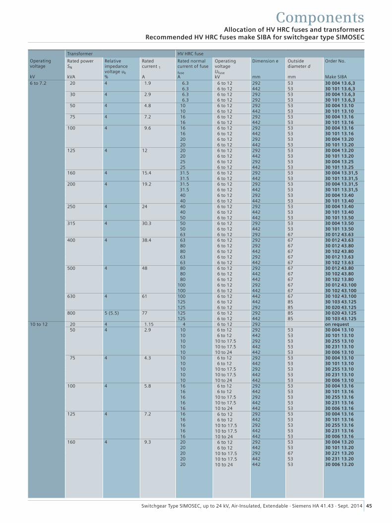
45Switchgear Type SIMOSEC, up to 24 kV, Air-Insulated, Extendable · Siemens HA 41.43 · Sept. 2014
Allocation of HV HRC fuses and transformersRecommended HV HRC fuses make SIBA for switchgear type SIMOSEC
Components
Operating voltage kV
Transformer HV HRC fuse
Rated power SN kVA
Relativeimpedance voltage uk %
Rated current 1 A
Rated normal current of fuse fuse A
Operating voltage Ufuse kV
Dimension e mm
Outside diameter d mm
Order No. Make SIBA
6 to 7.2 20 4 1.9 6.3 6 to 12 292 53 30 004 13.6,3 6.3 6 to 12 442 53 30 101 13.6,3
30 4 2.9 6.3 6 to 12 292 53 30 004 13.6,3 6.3 6 to 12 292 53 30 101 13.6,3
50 4 4.8 10 6 to 12 292 53 30 004 13.1010 6 to 12 442 53 30 101 13.10
75 4 7.2 16 6 to 12 292 53 30 004 13.1616 6 to 12 442 53 30 101 13.16
100 4 9.6 16 6 to 12 292 53 30 004 13.1616 6 to 12 442 53 30 101 13.1620 6 to 12 292 53 30 004 13.2020 6 to 12 442 53 30 101 13.20
125 4 12 20 6 to 12 292 53 30 004 13.2020 6 to 12 442 53 30 101 13.2025 6 to 12 292 53 30 004 13.2525 6 to 12 442 53 30 101 13.25
160 4 15.4 31.5 6 to 12 292 53 30 004 13.31,5 31.5 6 to 12 442 53 30 101 13.31,5
200 4 19.2 31.5 6 to 12 292 53 30 004 13.31,5 31.5 6 to 12 442 53 30 101 13.31,5
40 6 to 12 292 53 30 004 13.4040 6 to 12 442 53 30 101 13.40
250 4 24 40 6 to 12 292 53 30 004 13.4040 6 to 12 442 53 30 101 13.4050 6 to 12 442 53 30 101 13.50
315 4 30.3 50 6 to 12 292 53 30 004 13.5050 6 to 12 442 53 30 101 13.5063 6 to 12 292 67 30 012 43.63
400 4 38.4 63 6 to 12 292 67 30 012 43.6380 6 to 12 292 67 30 012 43.8080 6 to 12 442 67 30 102 43.8063 6 to 12 292 67 30 012 13.6363 6 to 12 442 67 30 102 13.63
500 4 48 80 6 to 12 292 67 30 012 43.8080 6 to 12 442 67 30 102 43.8080 6 to 12 442 67 30 102 13.80
100 6 to 12 292 67 30 012 43.100100 6 to 12 442 67 30 102 43.100
630 4 61 100 6 to 12 442 67 30 102 43.100125 6 to 12 442 85 30 103 43.125125 6 to 12 292 85 30 020 43.125
800 5 (5.5) 77 125 6 to 12 292 85 30 020 43.125125 6 to 12 442 85 30 103 43.125
10 to 12 20 4 1.15 4 6 to 12 292 on request50 4 2.9 10 6 to 12 292 53 30 004 13.10
10 6 to 12 442 53 30 101 13.1010 10 to 17.5 292 53 30 255 13.1010 10 to 17.5 442 53 30 231 13.1010 10 to 24 442 53 30 006 13.10
75 4 4.3 10 6 to 12 292 53 30 004 13.1010 6 to 12 442 53 30 101 13.1010 10 to 17.5 292 53 30 255 13.1010 10 to 17.5 442 53 30 231 13.1010 10 to 24 442 53 30 006 13.10
100 4 5.8 16 6 to 12 292 53 30 004 13.1616 6 to 12 442 53 30 101 13.1616 10 to 17.5 292 53 30 255 13.1616 10 to 17.5 442 53 30 231 13.1616 10 to 24 442 53 30 006 13.16
125 4 7.2 16 6 to 12 292 53 30 004 13.1616 6 to 12 442 53 30 101 13.1616 10 to 17.5 292 53 30 255 13.1616 10 to 17.5 442 53 30 231 13.1616 10 to 24 442 53 30 006 13.16
160 4 9.3 20 6 to 12 292 53 30 004 13.2020 6 to 12 442 53 30 101 13.2020 10 to 17.5 292 67 30 221 13.2020 10 to 17.5 442 53 30 231 13.2020 10 to 24 442 53 30 006 13.20
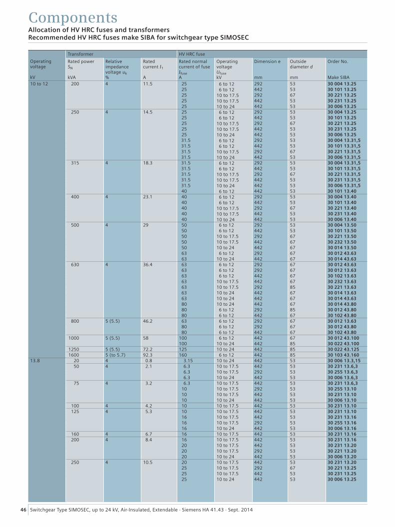
46 Switchgear Type SIMOSEC, up to 24 kV, Air-Insulated, Extendable · Siemens HA 41.43 · Sept. 2014
ComponentsAllocation of HV HRC fuses and transformersRecommended HV HRC fuses make SIBA for switchgear type SIMOSEC
Operating voltage kV
Transformer HV HRC fuse
Rated power SN kVA
Relativeimpedance voltage uk %
Rated current I1 A
Rated normal current of fuse Ifuse A
Operating voltage Ufuse kV
Dimension e mm
Outside diameter d mm
Order No. Make SIBA
10 to 12 200 4 11.5 25 6 to 12 292 53 30 004 13.2525 6 to 12 442 53 30 101 13.2525 10 to 17.5 292 67 30 221 13.2525 10 to 17.5 442 53 30 231 13.2525 10 to 24 442 53 30 006 13.25
250 4 14.5 25 6 to 12 292 53 30 004 13.2525 6 to 12 442 53 30 101 13.2525 10 to 17.5 292 67 30 221 13.2525 10 to 17.5 442 53 30 231 13.2525 10 to 24 442 53 30 006 13.25
31.5 6 to 12 292 53 30 004 13.31,5 31.5 6 to 12 442 53 30 101 13.31,5 31.5 10 to 17.5 292 67 30 221 13.31,5 31.5 10 to 24 442 53 30 006 13.31,5
315 4 18.3 31.5 6 to 12 292 53 30 004 13.31,5 31.5 6 to 12 442 53 30 101 13.31,5 31.5 10 to 17.5 292 67 30 221 13.31,5 31.5 10 to 17.5 442 53 30 231 13.31,5 31.5 10 to 24 442 53 30 006 13.31,5
40 6 to 12 442 53 30 101 13.40400 4 23.1 40 6 to 12 292 53 30 004 13.40
40 6 to 12 442 53 30 101 13.4040 10 to 17.5 292 67 30 221 13.4040 10 to 17.5 442 53 30 231 13.4040 10 to 24 442 53 30 006 13.40
500 4 29 50 6 to 12 292 53 30 004 13.5050 6 to 12 442 53 30 101 13.5050 10 to 17.5 292 67 30 221 13.5050 10 to 17.5 442 67 30 232 13.5050 10 to 24 442 67 30 014 13.5063 6 to 12 292 67 30 012 43.6363 10 to 24 442 67 30 014 43.63
630 4 36.4 63 6 to 12 292 67 30 012 43.6363 6 to 12 292 67 30 012 13.6363 6 to 12 442 67 30 102 13.6363 10 to 17.5 442 67 30 232 13.6363 10 to 17.5 292 85 30 221 13.6363 10 to 24 442 67 30 014 13.6363 10 to 24 442 67 30 014 43.6380 10 to 24 442 67 30 014 43.8080 6 to 12 292 85 30 012 43.8080 6 to 12 442 67 30 102 43.80
800 5 (5.5) 46.2 63 6 to 12 292 67 30 012 13.6380 6 to 12 292 67 30 012 43.8080 6 to 12 442 67 30 102 43.80
1000 5 (5.5) 58 100 6 to 12 442 67 30 012 43.100100 10 to 24 442 85 30 022 43.100
1250 5 (5.5) 72.2 125 10 to 24 442 85 30 022 43.1251600 5 (to 5.7) 92.3 160 6 to 12 442 85 30 103 43.160
13.8 20 4 0.8 3.15 10 to 24 442 53 30 006 13.3,1550 4 2.1 6.3 10 to 17.5 442 53 30 231 13.6,3
6.3 10 to 17.5 292 53 30 255 13.6,3 6.3 10 to 24 442 53 30 006 13.6,3
75 4 3.2 6.3 10 to 17.5 442 53 30 231 13.6,310 10 to 17.5 292 53 30 255 13.1010 10 to 17.5 442 53 30 231 13.1010 10 to 24 442 53 30 006 13.10
100 4 4.2 10 10 to 17.5 442 53 30 231 13.10125 4 5.3 10 10 to 17.5 442 53 30 231 13.10
16 10 to 17.5 442 53 30 231 13.1616 10 to 17.5 292 53 30 255 13.1616 10 to 24 442 53 30 006 13.16
160 4 6.7 16 10 to 17.5 442 53 30 231 13.16200 4 8.4 16 10 to 17.5 442 53 30 231 13.16
20 10 to 17.5 442 53 30 231 13.2020 10 to 17.5 292 53 30 221 13.2020 10 to 24 442 53 30 006 13.20
250 4 10.5 20 10 to 17.5 442 53 30 231 13.2025 10 to 17.5 292 67 30 221 13.2525 10 to 17.5 442 53 30 231 13.2525 10 to 24 442 53 30 006 13.25
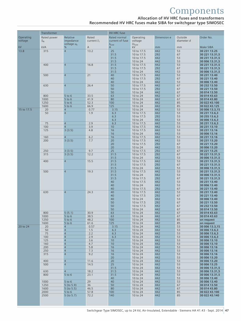
47Switchgear Type SIMOSEC, up to 24 kV, Air-Insulated, Extendable · Siemens HA 41.43 · Sept. 2014
ComponentsAllocation of HV HRC fuses and transformers
Recommended HV HRC fuses make SIBA for switchgear type SIMOSEC
Operating voltage kV
Transformer HV HRC fuse
Rated power SN kVA
Relativeimpedance voltage uk %
Rated current I1 A
Rated normal current of fuse Ifuse A
Operating voltage Ufuse kV
Dimension e mm
Outside diameter d mm
Order No. Make SIBA
13.8 315 4 13.2 25 10 to 17.5 442 53 30 231 13.25 31.5 10 to 17.5 292 67 30 221 13.31,5 31.5 10 to 17.5 442 53 30 231 13.31,5 31.5 10 to 24 442 53 30 006 13.31,5
400 4 16.8 31.5 10 to 17.5 442 53 30 231 13.31,5 31.5 10 to 17.5 292 67 30 221 13.31,5 31.5 10 to 24 442 53 30 006 13.31,5
500 4 21 40 10 to 17.5 442 53 30 231 13.40 40 10 to 17.5 292 67 30 221 13.4040 10 to 24 442 53 30 006 13.40
630 4 26.4 50 10 to 17.5 442 67 30 232 13.50 50 10 to 17.5 292 67 30 221 13.5050 10 to 24 442 67 30 014 13.50
800 5 to 6 33.5 63 10 to 24 442 67 30 014 43.631000 5 to 6 41.9 80 10 to 24 442 67 30 014 43.801250 5 to 6 52.3 100 10 to 24 442 85 30 022 43.1001600 5 to 6 66.9 125 10 to 24 442 85 30 022 43.125
15 to 17.5 20 4 0.77 3.15 10 to 24 442 53 30 006 13.3,1550 4 1.9 6.3 10 to 17.5 442 53 30 231 13.6,3
6.3 10 to 17.5 292 53 30 255 13.6,3 6.3 10 to 24 442 53 30 006 13.6,3
75 4 2.9 6.3 10 to 17.5 442 53 30 231 13.6,3100 4 3.9 10 10 to 17.5 442 53 30 231 13.10125 3 (3.5) 4.8 16 10 to 17.5 442 53 30 231 13.16
16 10 to 24 442 53 30 006 13.16160 4 6.2 16 10 to 17.5 442 53 30 231 13.16200 3 (3.5) 7.7 20 10 to 17.5 442 53 30 231 13.20
20 10 to 17.5 292 67 30 221 13.2020 10 to 24 442 53 30 006 13.20
250 3 (3.5) 9.7 25 10 to 17.5 292 67 30 221 13.25315 3 (3.5) 12.2 31.5 10 to 17.5 292 67 30 221 13.31,5
31.5 10 to 24 442 53 30 006 13.31,5400 4 15.5 31.5 10 to 17.5 442 53 30 231 13.31,5
31.5 10 to 17.5 292 67 30 221 13.31,5 31.5 10 to 24 442 53 30 006 13.31,5
500 4 19.3 31.5 10 to 17.5 442 53 30 231 13.31,5 31.5 10 to 24 442 53 30 006 13.31,5 31.5 10 to 17.5 292 67 30 221 13.31,5
40 10 to 17.5 442 53 30 231 13.4040 10 to 24 442 53 30 006 13.4040 10 to 17.5 292 67 30 221 13.40
630 4 24.3 40 10 to 17.5 442 53 30 231 13.4040 10 to 17.5 292 67 30 221 13.4040 10 to 24 442 53 30 006 13.4050 10 to 17.5 292 67 30 221 13.5050 10 to 17.5 442 67 30 232 13.5050 10 to 24 442 67 30 014 13.50
800 5 (5.1) 30.9 63 10 to 24 442 67 30 014 43.631000 5 to 6 38.5 63 10 to 24 442 67 30 014 43.631250 5 to 6 48.2 100 10 to 24 442 85 on request1600 5 to 6 61.6 125 10 to 24 442 85 on request
20 to 24 20 4 0.57 3.15 10 to 24 442 53 30 006 13.3,1550 4 1.5 6.3 10 to 24 442 53 30 006 13.6,375 4 2.2 6.3 10 to 24 442 53 30 006 13.6,3
100 4 2.9 6.3 10 to 24 442 53 30 006 13.6,3125 4 3.6 10 10 to 24 442 53 30 006 13.10160 4 4.7 10 10 to 24 442 53 30 006 13.10200 4 5.8 16 10 to 24 442 53 30 006 13.16250 4 7.3 16 10 to 24 442 53 30 006 13.16315 4 9.2 16 10 to 24 442 53 30 006 13.16
20 10 to 24 442 53 30 006 13.20400 4 11.6 20 10 to 24 442 53 30 006 13.20500 4 14.5 25 10 to 24 442 53 30 006 13.25
31.5 10 to 24 442 53 30 006 13.31,5630 4 18.2 31.5 10 to 24 442 53 30 006 13.31,5800 5 to 6 23.1 31.5 10 to 24 442 53 30 006 13.31,5
40 10 to 24 442 53 30 006 13.401000 5 to 6 29 40 10 to 24 442 53 30 006 13.401250 5 (to 5.9) 36 50 10 to 24 442 67 30 014 13.501600 5 (to 5.5) 46.5 80 10 to 24 442 67 30 014 43.802000 5 to 6 57.8 100 10 to 24 442 85 30 022 43.1002500 5 (to 5.7) 72.2 140 10 to 24 442 85 30 022 43.140
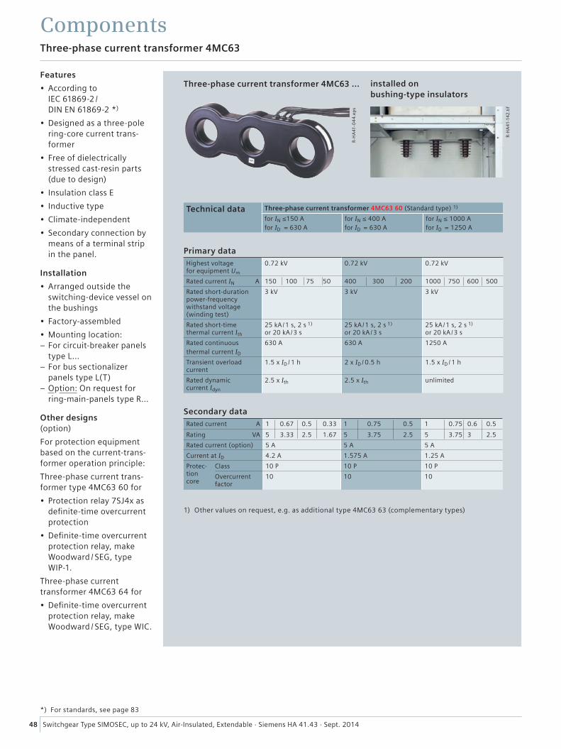
R-H
A41
-04
4.e
ps
R-H
A41
-142
.tif
48 Switchgear Type SIMOSEC, up to 24 kV, Air-Insulated, Extendable · Siemens HA 41.43 · Sept. 2014
ComponentsThree-phase current transformer 4MC63
Features
• According to IEC 61869-2 / DIN EN 61869-2 *)
• Designed as a three-pole ring-core current trans-former
• Free of dielectrically stressed cast-resin parts (due to design)
• Insulation class E
• Inductive type
• Climate-independent
• Secondary connection by means of a terminal strip in the panel.
Installation
• Arranged outside the switching-device vessel on the bushings
• Factory-assembled
• Mounting location: – For circuit-breaker panels type L...
– For bus sectionalizer panels type L(T)
– Option: On request for ring-main-panels type R...
Other designs (option)
For protection equipment based on the current-trans-former operation principle:
Three-phase current trans-former type 4MC63 60 for
• Protection relay 7SJ4x as definite-time overcurrent protection
• Definite-time overcurrent protection relay, make Woodward / SEG, type WIP-1.
Three-phase current transformer 4MC63 64 for
• Definite-time overcurrent protection relay, make Woodward / SEG, type WIC.
Three-phase current transformer 4MC63 ...
Technical data Three-phase current transformer 4MC63 60 (Standard type) 1)
for IN ≤150 A for ID = 630 A
for IN ≤ 400 A for ID = 630 A
for IN ≤ 1000 A for ID = 1250 A
Primary dataHighest voltage for equipment Um
0.72 kV 0.72 kV 0.72 kV
Rated current IN A 150 100 75 50 400 300 200 1000 750 600 500
Rated short-duration power-frequency withstand voltage (winding test)
3 kV 3 kV 3 kV
Rated short-time thermal current Ith
25 kA /1 s, 2 s 1) or 20 kA /3 s
25 kA /1 s, 2 s 1) or 20 kA /3 s
25 kA /1 s, 2 s 1) or 20 kA /3 s
Rated continuousthermal current ID
630 A 630 A 1250 A
Transient overload current
1.5 x ID / 1 h 2 x ID / 0.5 h 1.5 x ID / 1 h
Rated dynamic current Idyn
2.5 x Ith 2.5 x Ith unlimited
Secondary dataRated current A 1 0.67 0.5 0.33 1 0.75 0.5 1 0.75 0.6 0.5
Rating VA 5 3.33 2.5 1.67 5 3.75 2.5 5 3.75 3 2.5
Rated current (option) 5 A 5 A 5 A
Current at ID 4.2 A 1.575 A 1.25 A
Protec-tion core
Class 10 P 10 P 10 P
Overcurrent factor
10 10 10
1) Other values on request, e.g. as additional type 4MC63 63 (complementary types)
*) For standards, see page 83
installed on bushing-type insulators
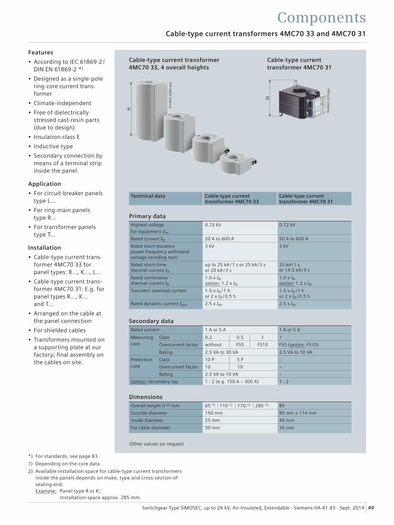
H
H
R-H
A41
-02
5 e
ps
R-H
A41
-024
a ep
s
49Switchgear Type SIMOSEC, up to 24 kV, Air-Insulated, Extendable · Siemens HA 41.43 · Sept. 2014
ComponentsCable-type current transformers 4MC70 33 and 4MC70 31
Features
• According to IEC 61869-2 / DIN EN 61869-2 *)
• Designed as a single-pole ring-core current trans-former
• Climate-independent
• Free of dielectrically stressed cast-resin parts (due to design)
• Insulation class E
• Inductive type
• Secondary connection by means of a terminal strip inside the panel.
Application
• For circuit-breaker panels type L...
• For ring-main panels type R...
• For transformer panels type T...
Installation
• Cable-type current trans-former 4MC70 33 for panel types: R..., K..., L...
• Cable-type current trans-former 4MC70 31: E.g. for panel types R..., K... and T...
• Arranged on the cable at the panel connection
• For shielded cables
• Transformers mounted on a supporting plate at our factory; final assembly on the cables on site.
Cable-type current transformer 4MC70 33, 4 overall heights
Cable-type current transformer 4MC70 31
Technical data Cable-type current transformer 4MC70 33
Cable-type current transformer 4MC70 31
Primary dataHighest voltage
for equipment Um
0.72 kV 0.72 kV
Rated current IN 20 A to 600 A 50 A to 600 A
Rated short-duration power-frequency withstand voltage (winding test)
3 kV 3 kV
Rated short-time thermal current Ith
up to 25 kA / 1 s or 25 kA /3 s or 20 kA / 3 s
25 kA /1 s, or 14.5 kA /3 s
Rated continuous thermal current ID
1.0 x IN option: 1.2 x IN
1.0 x IN option: 1.2 x IN
Transient overload current 1.5 x ID / 1 h or 2 x ID / 0.5 h
1.5 x ID / 1 h or 2 x ID / 0.5 h
Rated dynamic current Idyn 2.5 x Ith 2.5 x Ith
Secondary dataRated current 1 A or 5 A 1 A or 5 A
Measuring
core
Class 0.2 0.5 1 1
Overcurrent factor without FS5 FS10 FS5 (option: FS10)
Rating 2.5 VA to 30 VA 2.5 VA to 10 VA
Protection
core
Class 10 P 5 P –
Overcurrent factor 10 10 –
Rating 2.5 VA to 10 VA –
Option: Secondary tap 1 : 2 (e.g. 150 A – 300 A) 1 : 2
DimensionsOverall height H 2) mm 65 1) 110 1) 170 1) 285 1) 89
Outside diameter 150 mm 85 mm x 114 mm
Inside diameter 55 mm 40 mm
For cable diameter 50 mm 36 mm
Other values on request
*) For standards, see page 83
1) Depending on the core data
2) Available installation space for cable-type current transformers inside the panels depends on make, type and cross-section of sealing end. Example: Panel type R or K: Installation space approx. 285 mm
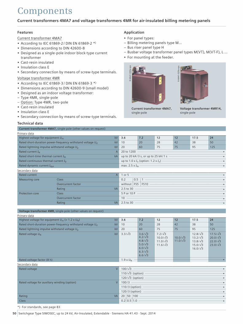
R-H
A41
-03
0a
eps
R-H
A41
-02
9a
eps
50 Switchgear Type SIMOSEC, up to 24 kV, Air-Insulated, Extendable · Siemens HA 41.43 · Sept. 2014
Technical dataCurrent transformer 4MA7, single-pole (other values on request)
Primary data
Highest voltage for equipment Um kV 3.6 7.2 12 12 17.5 24
Rated short-duration power-frequency withstand voltage Ud kV 10 20 28 42 38 50
Rated lightning impulse withstand voltage Up kV 20 60 75 75 95 125
Rated current IN A 20 to 1200
Rated short-time thermal current Ith kA up to 20 kA / 3 s, or up to 25 kA / 1 s
Rated continuous thermal current ID up to 1.0 x In (option: 1.2 x In)
Rated dynamic current Idyn max. 2.5 x Ith
Secondary data
Rated current A 1 or 5
Measuring core Class 0.2 0.5 1
Overcurrent factor without FS5 FS10
Rating VA 2.5 to 30
Protection core Class 5 P or 10 P
Overcurrent factor 10
Rating VA 2.5 to 30
Voltage transformer 4MR, single-pole (other values on request)
Primary data
Highest voltage for equipment Um (= 1.2 x UN) kV 3.6 7.2 12 12 17.5 24
Rated short-duration power-frequency withstand voltage Ud kV 10 20 28 42 38 50
Rated lightning impulse withstand voltage Up kV 20 60 75 75 95 125
Rated voltage UN kV 3.3 / √3 3.6 / √3 4.2 / √34.8 / √35.0 / √36.0 / √36.3 / √36.6 / √3
7.2 / √310.0 / √311.0 / √311.6 / √3
10.0 / √3 11.0 / √3
12.8 / √313.2 / √313.8 / √315.0 / √316.0 / √3
17.5 / √320.0 / √322.0 / √323.0 / √3
Rated voltage factor (8 h) 1.9 x UN
Secondary data
Rated voltage V 100 / √3
110 / √3 (option)
120 / √3 (option)
Rated voltage for auxiliary winding (option) V 100 / 3
110 / 3 (option)
120 / 3 (option)
Rating VA 20 50 100
Class 0.2 0.5 1.0
Current transformers 4MA7 and voltage transformers 4MR for air-insulated billing metering panels
Features
Current transformer 4MA7• According to IEC 61869-2 / DIN EN 61869-2 *)
• Dimensions according to DIN 42600-8• Designed as a single-pole indoor block-type current
transformer• Cast-resin insulated• Insulation class E• Secondary connection by means of screw-type terminals.
Voltage transformer 4MR• According to IEC 61869-3 / DIN EN 61869-3 *)
• Dimensions according to DIN 42600-9 (small model)• Designed as an indoor voltage transformer:
– Type 4MR, single-pole – Option: Type 4MR, two-pole
• Cast-resin insulated• Insulation class E• Secondary connection by means of screw-type terminals.
Current transformer 4MA7,single-pole
Voltage transformer 4MR14,single-pole
Application
• For panel types: – Billing metering panels type M... – Bus riser panel type H – Busbar voltage transformer panel types M(VT), M(VT-F), L …
• For mounting at the feeder.
*) For standards, see page 83
Components
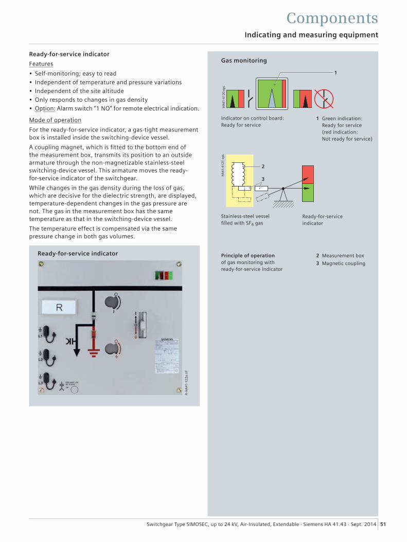
�
�
���
����
������
���
����
������
�
R-H
A41
-12
2a.
tif
51Switchgear Type SIMOSEC, up to 24 kV, Air-Insulated, Extendable · Siemens HA 41.43 · Sept. 2014
ComponentsIndicating and measuring equipment
Ready-for-service indicator
Features
• Self-monitoring; easy to read• Independent of temperature and pressure variations• Independent of the site altitude• Only responds to changes in gas density• Option: Alarm switch “1 NO” for remote electrical indication.
Mode of operation
For the ready-for-service indicator, a gas-tight measurement box is installed inside the switching-device vessel.
A coupling magnet, which is fitted to the bottom end of the measurement box, transmits its position to an outside armature through the non-magnetizable stainless-steel switching-device vessel. This armature moves the ready- for-service indicator of the switchgear.
While changes in the gas density during the loss of gas, which are decisive for the dielectric strength, are displayed, temperature-dependent changes in the gas pressure are not. The gas in the measurement box has the same temperature as that in the switching-device vessel.
The temperature effect is compensated via the same pressure change in both gas volumes.
Gas monitoring
Indicator on control board: Ready for service
Stainless-steel vessel filled with SF6 gas
Principle of operation of gas monitoring with ready-for-service indicator
2 Measurement box
3 Magnetic coupling
Ready-for-service indicator
1 Green indication: Ready for service (red indication: Not ready for service)
Ready-for-service indicator
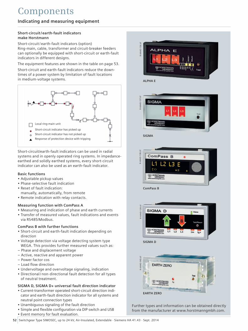
52 Switchgear Type SIMOSEC, up to 24 kV, Air-Insulated, Extendable · Siemens HA 41.43 · Sept. 2014
R-H
A4
0-1
37.
tif
R-H
A4
0-1
38
.tif
SIGMA
ALPHA E
ComPass B
R-H
A4
0-1
40
.tif
SIGMA D
EARTH ZERO
R-H
A4
0-1
39.
tif
R-H
A4
0-1
36
.tif
Indicating and measuring equipment
Components
Local ring-main unit
Short-circuit indicator has picked up
Short-circuit indicator has not picked up
Response of protection device with tripping
Further types and information can be obtained directly from the manufacturer at www.horstmanngmbh.com.
Short-circuit / earth-fault indicators make Horstmann
Short-circuit / earth-fault indicators (option) Ring-main, cable, transformer and circuit-breaker feeders can optionally be equipped with short-circuit or earth-fault indicators in different designs.
The equipment features are shown in the table on page 53.
Short-circuit and earth-fault indicators reduce the down-times of a power system by limitation of fault locations in medium-voltage systems.
Short-circuit/earth-fault indicators can be used in radial systems and in openly operated ring systems. In impedance-earthed and solidly earthed systems, every short-circuit indicator can also be used as an earth-fault indicator.
Basic functions• Adjustable pickup values• Phase-selective fault indication• Reset of fault indication:
manually, automatically, from remote• Remote indication with relay contacts.
Measuring function with ComPass A• Measuring and indication of phase and earth currents• Transfer of measured values, fault indications and events
via RS485/Modbus.
ComPass B with further functions• Short-circuit and earth-fault indication depending on
direction• Voltage detection via voltage detecting system type
WEGA. This provides further measured values such as: – Phase and displacement voltage – Active, reactive and apparent power – Power factor cos φ – Load flow direction
• Undervoltage and overvoltage signaling, indication• Directional / non-directional fault detection for all types
of neutral treatment.
SIGMA D, SIGMA D+ universal fault direction indicator• Current-transformer operated short-circuit direction indi-
cator and earth-fault direction indicator for all systems and neutral point connection types
• Unambiguous signaling of the fault direction• Simple and flexible configuration via DIP switch and USB• Event memory for fault evaluation.
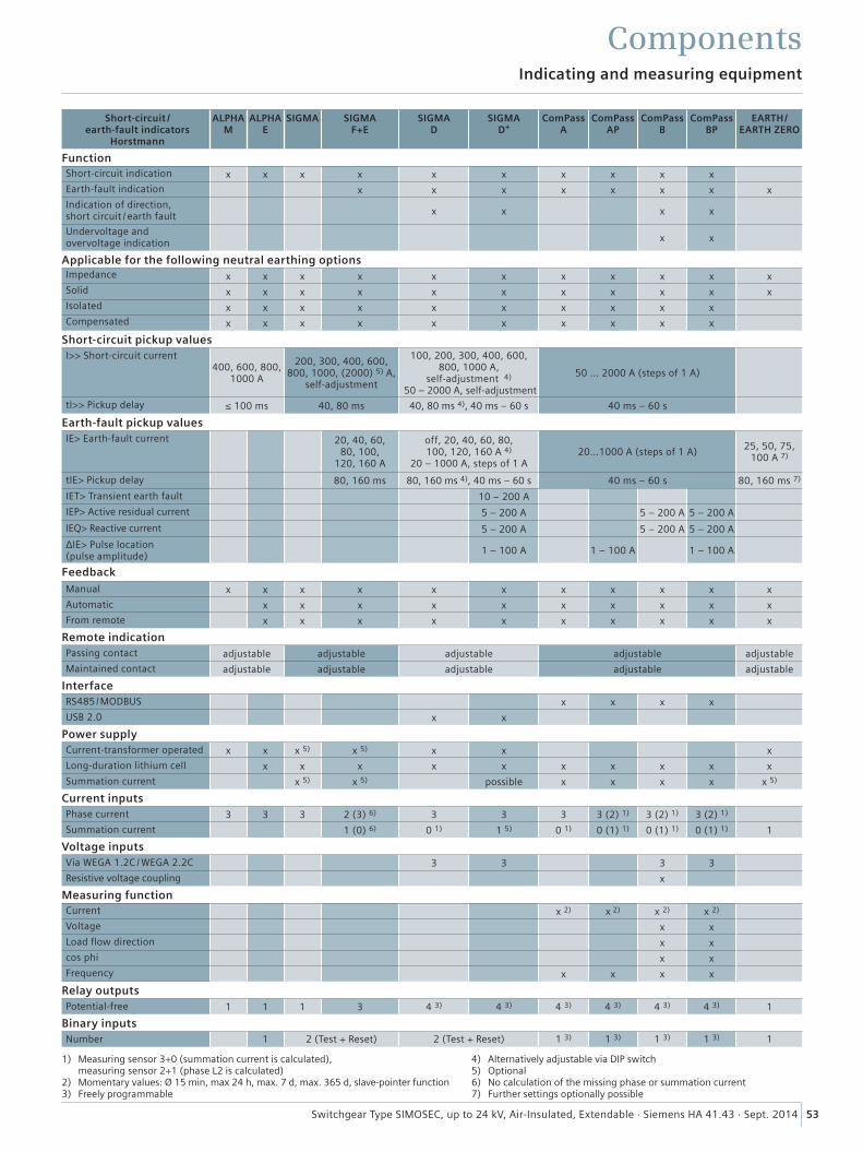
53Switchgear Type SIMOSEC, up to 24 kV, Air-Insulated, Extendable · Siemens HA 41.43 · Sept. 2014
Indicating and measuring equipment
Components
Short-circuit / earth-fault indicators
Horstmann
ALPHA M
ALPHA E
SIGMA SIGMA F+E
SIGMA D
SIGMA D+
ComPass A
ComPass AP
ComPass B
ComPass BP
EARTH/ EARTH ZERO
FunctionShort-circuit indication x x x x x x x x x x
Earth-fault indication x x x x x x x x
Indication of direction, short circuit / earth fault x x x x
Undervoltage and overvoltage indication x x
Applicable for the following neutral earthing optionsImpedance x x x x x x x x x x xSolid x x x x x x x x x x xIsolated x x x x x x x x x xCompensated x x x x x x x x x x
Short-circuit pickup valuesI>> Short-circuit current
400, 600, 800, 1000 A
200, 300, 400, 600, 800, 1000, (2000) 5) A,
self-adjustment
100, 200, 300, 400, 600, 800, 1000 A,
self-adjustment 4)
50 – 2000 A, self-adjustment
50 … 2000 A (steps of 1 A)
tI>> Pickup delay ≤ 100 ms 40, 80 ms 40, 80 ms 4), 40 ms – 60 s 40 ms – 60 s
Earth-fault pickup valuesIE> Earth-fault current 20, 40, 60,
80, 100, 120, 160 A
off, 20, 40, 60, 80, 100, 120, 160 A 4)
20 – 1000 A, steps of 1 A20…1000 A (steps of 1 A)
25, 50, 75, 100 A 7)
tIE> Pickup delay 80, 160 ms 80, 160 ms 4), 40 ms – 60 s 40 ms – 60 s 80, 160 ms 7)
IET> Transient earth fault 10 – 200 A
IEP> Active residual current 5 – 200 A 5 – 200 A 5 – 200 A
IEQ> Reactive current 5 – 200 A 5 – 200 A 5 – 200 A
ΔIE> Pulse location (pulse amplitude)
1 – 100 A 1 – 100 A 1 – 100 A
FeedbackManual x x x x x x x x x x x
Automatic x x x x x x x x x x
From remote x x x x x x x x x x
Remote indicationPassing contact adjustable adjustable adjustable adjustable adjustable
Maintained contact adjustable adjustable adjustable adjustable adjustable
InterfaceRS485/MODBUS x x x x
USB 2.0 x x
Power supplyCurrent-transformer operated x x x 5) x 5) x x x
Long-duration lithium cell x x x x x x x x x x
Summation current x 5) x 5) possible x x x x x 5)
Current inputsPhase current 3 3 3 2 (3) 6) 3 3 3 3 (2) 1) 3 (2) 1) 3 (2) 1)
Summation current 1 (0) 6) 0 1) 1 5) 0 1) 0 (1) 1) 0 (1) 1) 0 (1) 1) 1
Voltage inputsVia WEGA 1.2C / WEGA 2.2C 3 3 3 3
Resistive voltage coupling x
Measuring functionCurrent x 2) x 2) x 2) x 2)
Voltage x x
Load flow direction x x
cos phi x x
Frequency x x x x
Relay outputsPotential-free 1 1 1 3 4 3) 4 3) 4 3) 4 3) 4 3) 4 3) 1
Binary inputsNumber 1 2 (Test + Reset) 2 (Test + Reset) 1 3) 1 3) 1 3) 1 3) 1
1) Measuring sensor 3+0 (summation current is calculated),
measuring sensor 2+1 (phase L2 is calculated)2) Momentary values: Ø 15 min, max 24 h, max. 7 d, max. 365 d, slave-pointer function3) Freely programmable
4) Alternatively adjustable via DIP switch5) Optional6) No calculation of the missing phase or summation current7) Further settings optionally possible
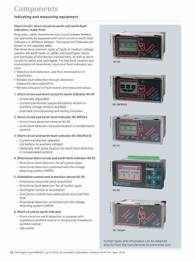
54 Switchgear Type SIMOSEC, up to 24 kV, Air-Insulated, Extendable · Siemens HA 41.43 · Sept. 2014
R-H
A4
0-1
41.t
ifR
-HA
40
-142
.tif
R-H
A4
0-1
43.t
ifR
-HA
40
-14
4.t
ifR
-HA
40
-14
5.t
if
IKI-20
IKI-20CPULS
IKI-22
IKI-50
IKI-10light
Indicating and measuring equipment
Components
Short-circuit / short-circuit-to-earth and earth-fault indicators, make Kries
Ring-main, cable, transformer and circuit-breaker feeders can optionally be equipped with short-circuit or earth-fault indicators in different designs. The equipment features are shown in the opposite table.The three most common types of faults in medium-voltage systems are earth faults in cables and switchgear, faults and overloads of distribution transformers, as well as short circuits in cables and switchgear. For fast fault location and minimization of downtimes, electronic fault indicators are used:• Selective fault detection, and thus minimization of
downtimes
• Reliable fault detection through electronic measured-value acquisition
• Remote indication of fault events and measured values.
1. Short-circuit and short-circuit-to-earth indicator IKI-20
– Universally adjustable
– Current-transformer supported battery version or auxiliary voltage versions available
– Extended commissioning and testing functions.
2. Short-circuit and earth-fault indicator IKI-20PULS
– Short-circuit detection same as IKI-20
– Earth-fault detection via pulse location in compensated systems.
3. Short-circuit and earth-fault indicator IKI-20C(PULS)
– Current-transformer operated (no battery no auxiliary voltage)
– Optionally with pulse location for earth-fault detection in compensated systems.
4. Directional short-circuit and earth-fault indicator IKI-22
– Directional fault detection for all system types
– Directional detection combined with the voltage detecting system CAPDIS.
5. Substation control and protection device IKI-50
– Directional measured-value acquisition
– Directional fault detection for all system types
– Switchgear control or automation
– One device controls two cable panels plus load flow total
– Directional detection combined with the voltage detecting system CAPDIS.
6. Short-circuit-to-earth indicator
– Short-circuit-to-earth detection in systems with impedance-earthed neutral or temporarily impedance earthed-neutral
– Adjustable.
Further types and information can be obtained directly from the manufacturer at www.kries.com.
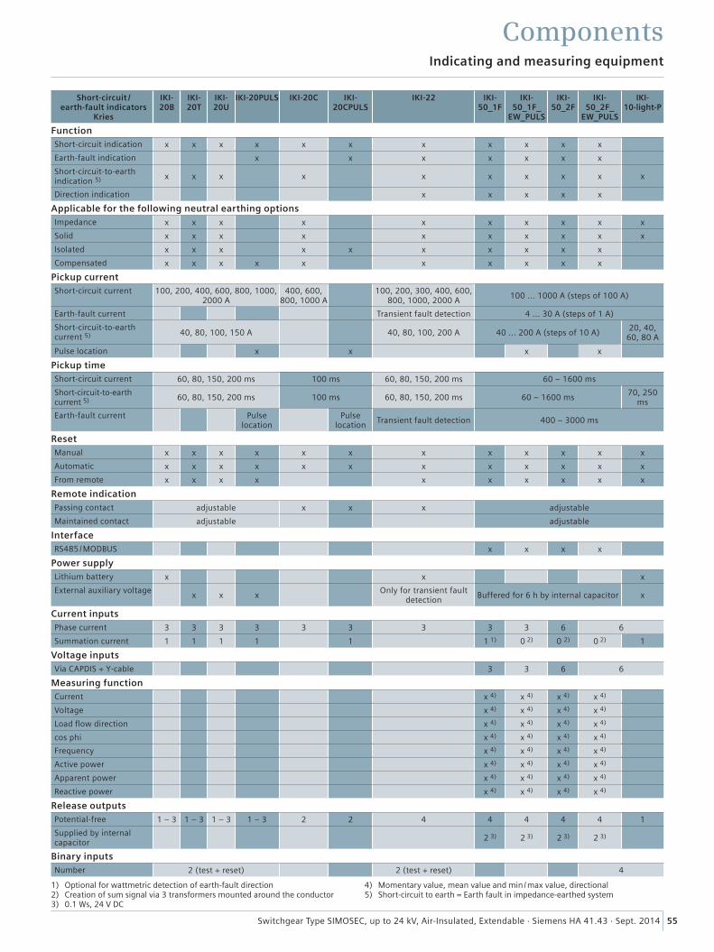
55Switchgear Type SIMOSEC, up to 24 kV, Air-Insulated, Extendable · Siemens HA 41.43 · Sept. 2014
Indicating and measuring equipment
Components
1) Optional for wattmetric detection of earth-fault direction2) Creation of sum signal via 3 transformers mounted around the conductor3) 0.1 Ws, 24 V DC
4) Momentary value, mean value and min / max value, directional5) Short-circuit to earth = Earth fault in impedance-earthed system
Short-circuit / earth-fault indicators
Kries
IKI- 20B
IKI- 20T
IKI- 20U
IKI-20PULS IKI-20C IKI-20CPULS
IKI-22 IKI- 50_1F
IKI- 50_1F_
EW_PULS
IKI- 50_2F
IKI- 50_2F_
EW_PULS
IKI-10-light-P
FunctionShort-circuit indication x x x x x x x x x x x
Earth-fault indication x x x x x x x
Short-circuit-to-earth indication 5) x x x x x x x x x x
Direction indication x x x x x
Applicable for the following neutral earthing optionsImpedance x x x x x x x x x x
Solid x x x x x x x x x x
Isolated x x x x x x x x x x
Compensated x x x x x x x x x x
Pickup currentShort-circuit current 100, 200, 400, 600, 800, 1000,
2000 A400, 600,
800, 1000 A100, 200, 300, 400, 600,
800, 1000, 2000 A100 ... 1000 A (steps of 100 A)
Earth-fault current Transient fault detection 4 ... 30 A (steps of 1 A)
Short-circuit-to-earth current 5) 40, 80, 100, 150 A 40, 80, 100, 200 A 40 ... 200 A (steps of 10 A)
20, 40, 60, 80 A
Pulse location x x x x
Pickup timeShort-circuit current 60, 80, 150, 200 ms 100 ms 60, 80, 150, 200 ms 60 – 1600 ms
Short-circuit-to-earth current 5) 60, 80, 150, 200 ms 100 ms 60, 80, 150, 200 ms 60 – 1600 ms
70, 250 ms
Earth-fault current Pulse location
Pulse location
Transient fault detection 400 – 3000 ms
ResetManual x x x x x x x x x x x x
Automatic x x x x x x x x x x x x
From remote x x x x x x x x x x
Remote indicationPassing contact adjustable x x x adjustable
Maintained contact adjustable adjustable
InterfaceRS485/MODBUS x x x x
Power supplyLithium battery x x x
External auxiliary voltagex x x
Only for transient fault detection
Buffered for 6 h by internal capacitor x
Current inputsPhase current 3 3 3 3 3 3 3 3 3 6 6
Summation current 1 1 1 1 1 1 1) 0 2) 0 2) 0 2) 1
Voltage inputsVia CAPDIS + Y-cable 3 3 6 6
Measuring functionCurrent x 4) x 4) x 4) x 4)
Voltage x 4) x 4) x 4) x 4)
Load flow direction x 4) x 4) x 4) x 4)
cos phi x 4) x 4) x 4) x 4)
Frequency x 4) x 4) x 4) x 4)
Active power x 4) x 4) x 4) x 4)
Apparent power x 4) x 4) x 4) x 4)
Reactive power x 4) x 4) x 4) x 4)
Release outputsPotential-free 1 – 3 1 – 3 1 – 3 1 – 3 2 2 4 4 4 4 4 1
Supplied by internal capacitor
2 3) 2 3) 2 3) 2 3)
Binary inputsNumber 2 (test + reset) 2 (test + reset) 4
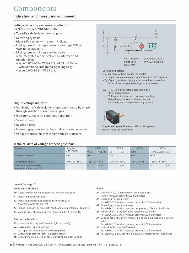
56 Switchgear Type SIMOSEC, up to 24 kV, Air-Insulated, Extendable · Siemens HA 41.43 · Sept. 2014
Indicating and measuring equipment
Components
���
����
������
�
���
��� ��� ��
����
��
Voltage indicationvia capacitive voltage divider (principle)– C1 Capacitive coupling electrode integrated into bushing– C2 Capacity of the coupling unit (as well as connection
leads of the voltage detecting system) to earth
ULE = UN / 3 during rated operation in the three-phase system
U2 Voltage at the interface (for plug-in voltage detecting system) or at the test socket (for integrated voltage detecting system)
Volt. indicatorplugged in (HR, LRM)
CAPDIS-Sx+, VOIS+ or WEGA installed
Voltage detecting systems according to IEC / EN 61243-5 or VDE 0682-415
• To verify safe isolation from supply
• Detecting systems – HR or LRM system with plug-in indicator – LRM system with integrated indicator, type VOIS+, VOIS R+, WEGA ZERO
– LRM system with integrated indicator, with integrated repeat test of the interface and function test: – type CAPDIS-S1+, WEGA 1.2, WEGA 1.2 Vario; with additional integrated signaling relay – type CAPDIS-S2+, WEGA 2.2.
Plug-in voltage indicator
• Verification of safe isolation from supply phase by phase through insertion in each socket pair
• Indicator suitable for continuous operation
• Safe-to-touch
• Routine-tested
• Measuring system and voltage indicator can be tested
• Voltage indicator flashes if high voltage is present.
Plug-in voltage indicator (as HR or LRM system) per phase at the panel front
R-H
A4
0-1
35
.tif
Technical data of voltage detecting systemsVersion HR system,
LRM systemVOIS CAPDIS WEGA WEGA
VOIS+ VOIS R+ -S1+ -S2+ ZERO 1.2 /1.2 Vario 2.2
Degree of protection IP54 IP67 IP54 IP54 IP54
Temperature range –40 °C to +55 °C –25 °C to +55 °C –25 °C to +55 °C –25 °C to +55 °C –25 °C to +55 °C
Integrated signaling relays (auxiliary voltage required)
– – with – with – – with
Legend for page 57
VOIS+ and CAPDIS-Sx
A0 Operating voltage not present. Active zero indication
A1 Operating voltage present
A2 Operating voltage not present. For CAPDIS-S2+: Auxiliary power not present
A3 Failure in phase L1, e.g. earth fault, operating voltage at L2 and L3
A4 Voltage present, appears in the range from 0.10...0.45 x Un
Test button function
A5 Indication “Display Test” passed (lights up briefly)
A6 CAPDIS-S2+: ERROR indication, e.g. open circuit or missing auxiliary power
A7 Overvoltage present (lights up permanently)A8 "ERROR" indication, e.g. in case of missing auxiliary voltage
WEGA
A0 For WEGA 2.2: Operating voltage not present, auxiliary power present, LCD illuminated
A1 Operating voltage present For WEGA 2.2: Auxiliary power present, LCD illuminated
A2 Operating voltage not present For WEGA 2.2: Auxiliary power not present, LCD not illuminated
A3 Failure in phase L1, operating voltage at L2 and L3 For WEGA 2.2: Auxiliary power present, LCD illuminated
A4 Voltage present, current monitoring of coupling section below limit value For WEGA 2.2: Auxiliary power present, LCD illuminated
A5 Indication "Display Test" passed For WEGA 2.2: Auxiliary power present, LCD illuminated
A6 For WEGA 2.2: LCD for missing auxiliary voltage is not illuminated
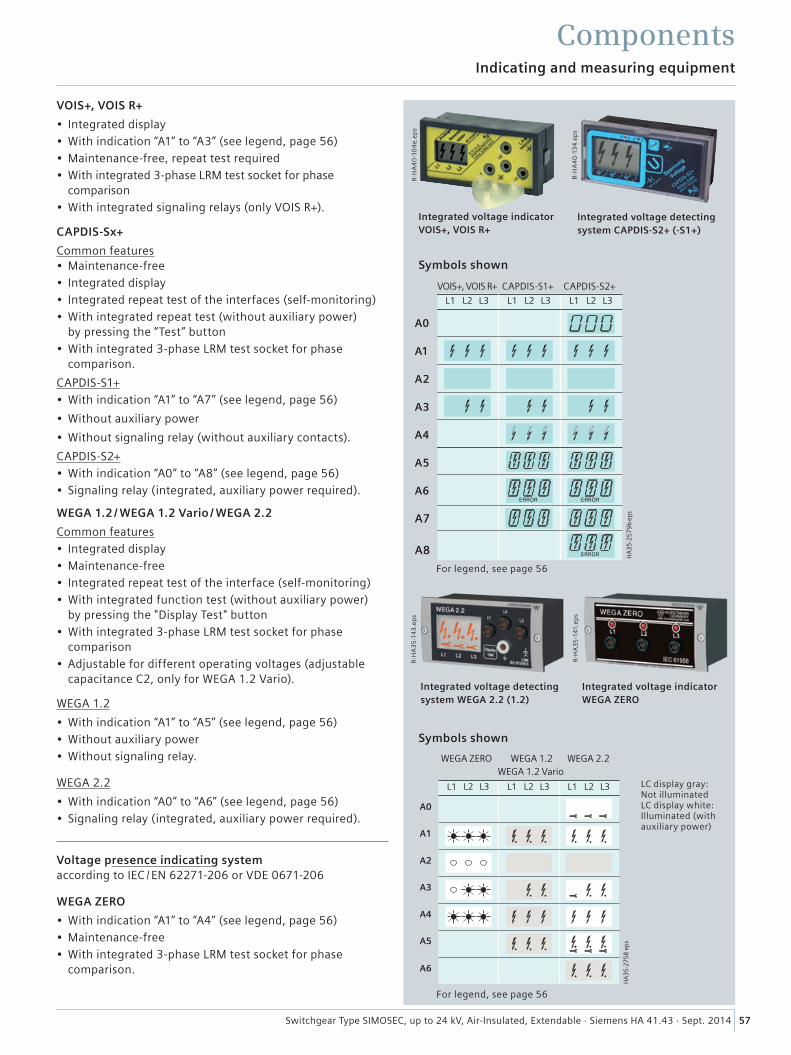
57Switchgear Type SIMOSEC, up to 24 kV, Air-Insulated, Extendable · Siemens HA 41.43 · Sept. 2014
Indicating and measuring equipment
Components
VOIS+, VOIS R+
• Integrated display• With indication “A1” to “A3” (see legend, page 56)• Maintenance-free, repeat test required• With integrated 3-phase LRM test socket for phase
comparison• With integrated signaling relays (only VOIS R+).
CAPDIS-Sx+
Common features• Maintenance-free• Integrated display• Integrated repeat test of the interfaces (self-monitoring)• With integrated repeat test (without auxiliary power)
by pressing the “Test” button• With integrated 3-phase LRM test socket for phase
comparison.
CAPDIS-S1+• With indication “A1” to “A7” (see legend, page 56)
• Without auxiliary power
• Without signaling relay (without auxiliary contacts).
CAPDIS-S2+• With indication “A0” to “A8” (see legend, page 56)• Signaling relay (integrated, auxiliary power required).
WEGA 1.2 / WEGA 1.2 Vario / WEGA 2.2
Common features• Integrated display• Maintenance-free• Integrated repeat test of the interface (self-monitoring)• With integrated function test (without auxiliary power)
by pressing the "Display Test" button• With integrated 3-phase LRM test socket for phase
comparison• Adjustable for different operating voltages (adjustable
capacitance C2, only for WEGA 1.2 Vario).
WEGA 1.2
• With indication “A1” to “A5” (see legend, page 56)• Without auxiliary power• Without signaling relay.
WEGA 2.2
• With indication “A0” to “A6” (see legend, page 56)• Signaling relay (integrated, auxiliary power required).
Voltage presence indicating system according to IEC / EN 62271-206 or VDE 0671-206
WEGA ZERO
• With indication “A1” to “A4” (see legend, page 56)• Maintenance-free• With integrated 3-phase LRM test socket for phase
comparison.
R-H
A4
0-1
34
.ep
s
Integrated voltage detecting system CAPDIS-S2+ (-S1+)
R-H
A4
0-1
04
e.ep
s
Integrated voltage indicator VOIS+, VOIS R+
Symbols shown
VOIS+, VOIS R+ CAPDIS-S1+ CAPDIS-S2+
For legend, see page 56
Symbols shown
LC display gray: Not illuminated LC display white: Illuminated (with auxiliary power)
For legend, see page 56
R-H
A3
5-1
41.e
ps
Integrated voltage indicator WEGA ZERO
R-H
A3
5-1
43.e
ps
Integrated voltage detecting system WEGA 2.2 (1.2)
A0
A1
A2
A3
A4
A5
A6
A7
A8
WEGA ZERO WEGA 1.2 WEGA 2.2 WEGA 1.2 Vario
���� �� ���� ������ ��
��
��
��
��
��
��
��
���
����
������
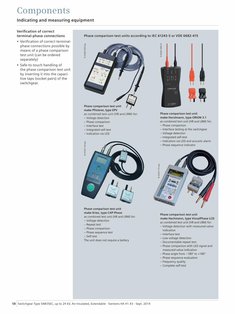
58 Switchgear Type SIMOSEC, up to 24 kV, Air-Insulated, Extendable · Siemens HA 41.43 · Sept. 2014
Indicating and measuring equipment
Components
R-H
A4
0-0
59
ep
sR
-HA
35
-124
.ep
s
Phase comparison test units according to IEC 61243-5 or VDE 0682-415Verification of correct terminal-phase connections
• Verification of correct terminal-phase connections possible by means of a phase comparison test unit (can be ordered separately)
• Safe-to-touch handling of the phase comparison test unit by inserting it into the capaci-tive taps (socket pairs) of the switchgear.
Phase comparison test unit make Pfisterer, type EPVas combined test unit (HR and LRM) for: – Voltage detection – Phase comparison – Interface test– Integrated self-test– Indication via LED
Phase comparison test unit make Kries, type CAP-Phase as combined test unit (HR and LRM) for:– Voltage detection– Repeat test– Phase comparison– Phase sequence test– Self-testThe unit does not require a battery
R-H
A3
5-1
75
.ep
s
Phase comparison test unit make Hachmann, type VisualPhase LCD as combined test unit (HR and LRM) for: – Voltage detection with measured-value
indication– Interface test – Low voltage detection – Documentable repeat test – Phase comparison with LED signal and
measured-value indication– Phase angle from –180° to +180°– Phase sequence evaluation – Frequency quality – Complete self-test
R-H
A4
0-0
89.
tif
Phase comparison test unit make Horstmann, type ORION 3.1 as combined test unit (HR and LRM) for: – Phase comparison – Interface testing at the switchgear – Voltage detection – Integrated self-test – Indication via LED and acoustic alarm – Phase sequence indicator
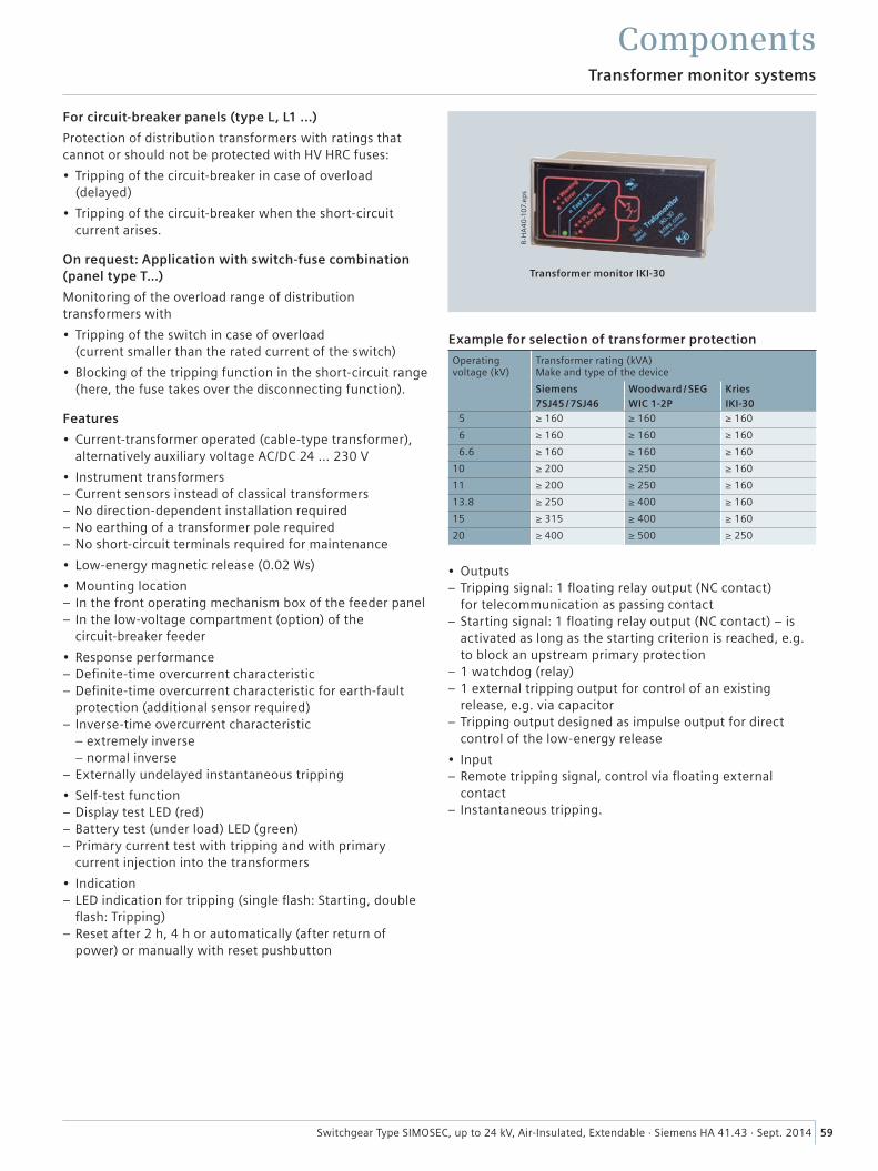
59Switchgear Type SIMOSEC, up to 24 kV, Air-Insulated, Extendable · Siemens HA 41.43 · Sept. 2014
For circuit-breaker panels (type L, L1 ...)
Protection of distribution transformers with ratings that cannot or should not be protected with HV HRC fuses:
• Tripping of the circuit-breaker in case of overload (delayed)
• Tripping of the circuit-breaker when the short-circuit current arises.
On request: Application with switch-fuse combination (panel type T…)
Monitoring of the overload range of distribution transformers with
• Tripping of the switch in case of overload (current smaller than the rated current of the switch)
• Blocking of the tripping function in the short-circuit range (here, the fuse takes over the disconnecting function).
Features
• Current-transformer operated (cable-type transformer), alternatively auxiliary voltage AC/DC 24 ... 230 V
• Instrument transformers – Current sensors instead of classical transformers – No direction-dependent installation required – No earthing of a transformer pole required – No short-circuit terminals required for maintenance
• Low-energy magnetic release (0.02 Ws)
• Mounting location – In the front operating mechanism box of the feeder panel – In the low-voltage compartment (option) of the circuit-breaker feeder
• Response performance – Definite-time overcurrent characteristic – Definite-time overcurrent characteristic for earth-fault protection (additional sensor required)
– Inverse-time overcurrent characteristic – extremely inverse – normal inverse
– Externally undelayed instantaneous tripping
• Self-test function – Display test LED (red) – Battery test (under load) LED (green) – Primary current test with tripping and with primary c urrent injection into the transformers
• Indication – LED indication for tripping (single flash: Starting, double flash: Tripping)
– Reset after 2 h, 4 h or automatically (after return of power) or manually with reset pushbutton
• Outputs – Tripping signal: 1 floating relay output (NC contact) for telecommunication as passing contact
– Starting signal: 1 floating relay output (NC contact) – is activated as long as the starting criterion is reached, e.g. to block an upstream primary protection
– 1 watchdog (relay) – 1 external tripping output for control of an existing release, e.g. via capacitor
– Tripping output designed as impulse output for direct control of the low-energy release
• Input – Remote tripping signal, control via floating external contact
– Instantaneous tripping.
Example for selection of transformer protection
Operating voltage (kV)
Transformer rating (kVA) Make and type of the device
Siemens Woodward / SEG Kries7SJ45 / 7SJ46 WIC 1-2P IKI-30
5 ≥ 160 ≥ 160 ≥ 160
6 ≥ 160 ≥ 160 ≥ 160
6.6 ≥ 160 ≥ 160 ≥ 160
10 ≥ 200 ≥ 250 ≥ 160
11 ≥ 200 ≥ 250 ≥ 160
13.8 ≥ 250 ≥ 400 ≥ 160
15 ≥ 315 ≥ 400 ≥ 160
20 ≥ 400 ≥ 500 ≥ 250
Transformer monitor systems
Components
R-H
A4
0-1
07.
eps
Transformer monitor IKI-30
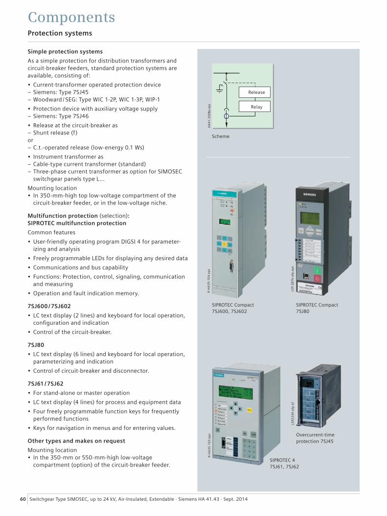
60 Switchgear Type SIMOSEC, up to 24 kV, Air-Insulated, Extendable · Siemens HA 41.43 · Sept. 2014
Protection systems
Components
����
����
������
R-H
A3
5-1
04
.ep
s
LSP
28
74-a
fp.e
ps
R-H
A3
5-1
03
.ep
s
Simple protection systems
As a simple protection for distribution transformers and circuit-breaker feeders, standard protection systems are available, consisting of:
• Current-transformer operated protection device – Siemens: Type 7SJ45 – Woodward / SEG: Type WIC 1-2P, WIC 1-3P, WIP-1
• Protection device with auxiliary voltage supply – Siemens: Type 7SJ46
• Release at the circuit-breaker as – Shunt release (f)
or – C.t.-operated release (low-energy 0.1 Ws)
• Instrument transformer as – Cable-type current transformer (standard) – Three-phase current transformer as option for SIMOSEC switchgear panels type L…
Mounting location• In 350-mm-high top low-voltage compartment of the
circuit-breaker feeder, or in the low-voltage niche.
Multifunction protection (selection): SIPROTEC multifunction protection
Common features
• User-friendly operating program DIGSI 4 for parameter-izing and analysis
• Freely programmable LEDs for displaying any desired data
• Communications and bus capability
• Functions: Protection, control, signaling, communication and measuring
• Operation and fault indication memory.
7SJ600 / 7SJ602
• LC text display (2 lines) and keyboard for local operation, configuration and indication
• Control of the circuit-breaker.
7SJ80
• LC text display (6 lines) and keyboard for local operation, parameterizing and indication
• Control of circuit-breaker and disconnector.
7SJ61 / 7SJ62
• For stand-alone or master operation
• LC text display (4 lines) for process and equipment data
• Four freely programmable function keys for frequently performed functions
• Keys for navigation in menus and for entering values.
Other types and makes on request
Mounting location• In the 350-mm or 550-mm-high low-voltage
compartment (option) of the circuit-breaker feeder.
Scheme
SIPROTEC Compact7SJ600, 7SJ602
SIPROTEC Compact7SJ80
LSP2
33
9-a
fp.t
if
Overcurrent-timeprotection 7SJ45
SIPROTEC 47SJ61, 7SJ62
Release
Relay
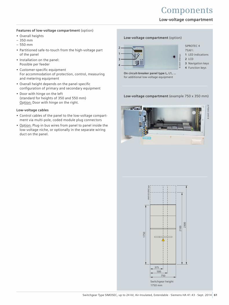
61Switchgear Type SIMOSEC, up to 24 kV, Air-Insulated, Extendable · Siemens HA 41.43 · Sept. 2014
Low-voltage compartment
Components
R-H
A41
-05
8 e
ps
����
����
����
���
����
����
����
���
���
���
R-H
A41
-04
0a
tif
2
1
3
4
Features of low-voltage compartment (option)
• Overall heights – 350 mm – 550 mm
• Partitioned safe-to-touch from the high-voltage part of the panel
• Installation on the panel: Possible per feeder
• Customer-specific equipment For accommodation of protection, control, measuring and metering equipment
• Overall height depends on the panel-specific configuration of primary and secondary equipment
• Door with hinge on the left (standard for heights of 350 and 550 mm) Option: Door with hinge on the right.
Low-voltage cables
• Control cables of the panel to the low-voltage compart-ment via multi-pole, coded module plug connectors
• Option: Plug-in bus wires from panel to panel inside the low-voltage niche, or optionally in the separate wiring duct on the panel.
Low-voltage compartment (example 750 x 350 mm)
Low-voltage compartment (option)
SIPROTEC 4
7SJ61:
1 LED indications
2 LCD
3 Navigation keys
4 Function keys
On circuit-breaker panel type L, L1, …for additional low-voltage equipment
Switchgear height1750 mm
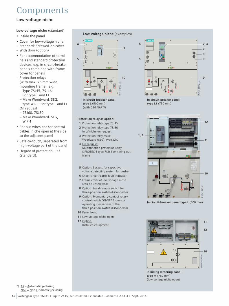
62 Switchgear Type SIMOSEC, up to 24 kV, Air-Insulated, Extendable · Siemens HA 41.43 · Sept. 2014
Low-voltage niche
Components
Low-voltage niche (standard)
• Inside the panel
• Cover for low-voltage niche: – Standard: Screwed-on cover – With door (option)
• For accommodation of termi-nals and standard protection devices, e.g. in circuit-breaker panels combined with frame cover for panels
– Protection relays (with max. 75 mm wide mounting frame), e.g. – Type 7SJ45, 7SJ46: For type L and L1 – Make Woodward / SEG,
type WIC1: For type L and L1 On request: – 7SJ60, 7SJ80 – Make Woodward / SEG,
WIP-1
• For bus wires and / or control cables; niche open at the side to the adjacent panel
• Safe-to-touch, separated from high-voltage part of the panel
• Degree of protection IP3X (standard).
Low-voltage niche (examples)
���
����
����
����
��
��
��
In billing metering panel type M (750 mm) (low-voltage niche open)
���
����
����
����
�
�����
�
�
�
��
�
In circuit-breaker panel type L (500 mm)(with CB-f NAR*))
���
����
����
����
�
�
�
��
In circuit-breaker panel type L1 (750 mm)
In circuit-breaker panel type L (500 mm)
Protection relay as option:
1 Protection relay type 7SJ45
2 Protection relay type 7SJ80 in LV niche on request
3 Protection relay make Woodward (SEG), type WIC
4 On request: Multifunction protection relay SIPROTEC 4 type 7SJ61 on swing-out frame
5 Option: Sockets for capacitive voltage detecting system for busbar
6 Short-circuit /earth-fault indicator
7 Frame cover of low-voltage niche (can be unscrewed)
8 Option: Local-remote switch for three- position switch-disconnector
9 Option: Momentary-contact rotary control switch ON-OFF for motor operating mechanism of the three-position switch-disconnector
10 Panel front
11 Low-voltage niche open
12 Option: Installed equipment
*) AR = Automatic reclosing NAR = Non automatic reclosing
12
11
10
1, 3
R-H
A41
-143
tif
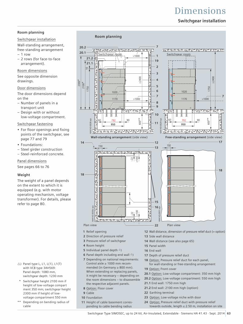
�����
��
���
����
����
����
���
����
���
���
����
���
��
��
��
��
��
��
���
����
����
����
�
���
����
���
����
�����
���� �����
����
����
�
����� ��
��
���
����
�
�
�
�
�
�
�
�
�
��
��
�
�
����
����
��
����
����
���
����
����
���
���
��
����� ��
����
�
�����
����
����
���
����
�
���
����
����
����
Dimensions
Room planning
Switchgear installation
Wall-standing arrangement, free-standing arrangement
– 1 row – 2 rows (for face-to-face arrangement).
Room dimensions
See opposite dimension drawings.
Door dimensions
The door dimensions depend on the
– Number of panels in a transport unit
– Design with or without low-voltage compartment.
Switchgear fastening
• For floor openings and fixing points of the switchgear, see page 77 and 79
• Foundations: – Steel girder construction – Steel-reinforced concrete.
Panel dimensions
See pages 66 to 76
Weight
The weight of a panel depends on the extent to which it is equipped (e.g. with motor operating mechanism, voltage transformer). For details, please refer to page 80.
Room planning
Switchgear room Switchgear room
) Panel type L, L1, L(1), L1(T) with VCB type 3AH569: Panel depth: 1080 mm, switchgear depth: 1230 mm
* Switchgear height 2100 mm if height of low-voltage compart ment 350 mm; switchgear height 2300 mm if height of low- voltage compartment 550 mm
** Depending on bending radius of cable
Wall-standing arrangement (side view)
Plan view
Free-standing arrangement (side view)
Plan view
1 Relief opening
2 Direction of pressure relief
3 Pressure relief of switchgear
4 Room height
5 Individual panel depth )
6 Panel depth including end wall )
7 Depending on national requirements: Control aisle ≥ 1000 mm recom- mended (in Germany ≥ 800 mm). When extending or replacing panels, it might be necessary – depending on the room dimensions – to disassemble the respective adjacent panels.
8 Option: Floor cover
9 Cable
10 Foundation
11 Height of cable basement corres- ponding to cable bending radius
12 Wall distance, dimension of pressure relief duct (= option)
13 Side wall distance
14 Wall distance (see also page 65)
15 Panel width
16 End wall
17 Depth of pressure relief duct
18 Option: Pressure relief duct for each panel, for wall-standing or free-standing arrangement
19 Option: Front cover
20.1 Option: Low-voltage compartment: 350 mm high
20.2 Option: Low-voltage compartment: 550 mm high
21.1 End wall: 1750 mm high
21.2 End wall: 2100 mm high (option)
22 Earthing terminal
23 Option: Low-voltage niche with door
24 Option: Pressure relief duct with pressure relief towards outside, length ≤ 2.50 m, installation on site
Switchgear installation
63Switchgear Type SIMOSEC, up to 24 kV, Air-Insulated, Extendable · Siemens HA 41.43 · Sept. 2014
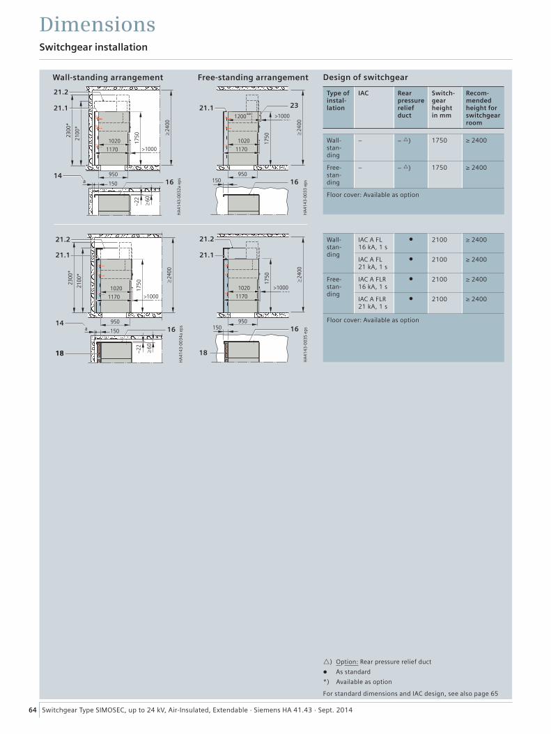
DimensionsSwitchgear installation
���
��
����
���
���
�����
����
�
����
�
��������
���� ��� ��
����
����
�����
����
����
���
� ���
���
��
�����
����
��������
����
�����
���� ��
���
����
����
����
���
��
����
���
���
�����
����
�
����
�
��������
���� ��� ��
����
����
��
��
���
����
����
���
�
��
���
���
��
�����
����
��������
���
��
��
����
����
���
����
����
����
Wall-standing arrangement Free-standing arrangement
64 Switchgear Type SIMOSEC, up to 24 kV, Air-Insulated, Extendable · Siemens HA 41.43 · Sept. 2014
Design of switchgear
Type of instal-lation
IAC Rear pressure relief duct
Switch- gear height in mm
Recom-mended height for switchgear room
Wall-stan-ding
– – ) 1750 ≥ 2400
Free-stan-ding
– – ) 1750 ≥ 2400
Floor cover: Available as option
Wall-stan-ding
IAC A FL 16 kA, 1 s
l 2100 ≥ 2400
IAC A FL 21 kA, 1 s
l 2100 ≥ 2400
Free-stan-ding
IAC A FLR 16 kA, 1 s
l 2100 ≥ 2400
IAC A FLR 21 kA, 1 s
l 2100 ≥ 2400
Floor cover: Available as option
) Option: Rear pressure relief duct
l As standard
*) Available as option
For standard dimensions and IAC design, see also page 65
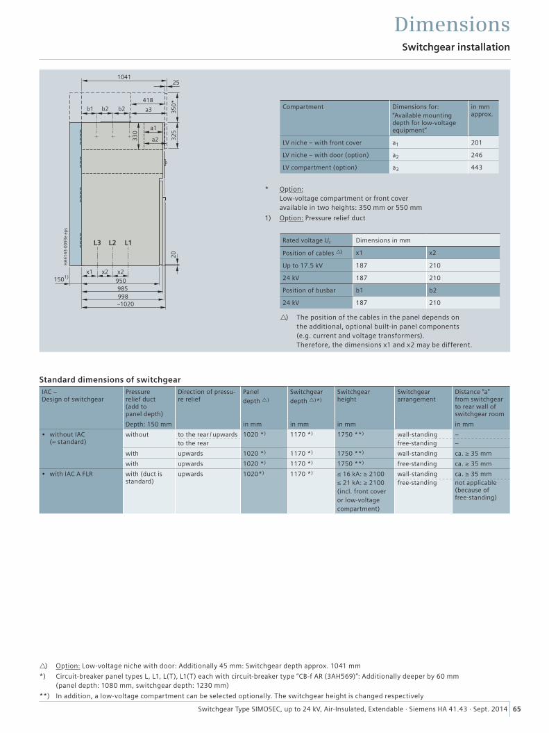
DimensionsSwitchgear installation
���
����
����
����
�
�� �� ��
��
�� �� �����
�����
����
�
��
���
��
������
�����
�� �� ��
���
����
���
��
65Switchgear Type SIMOSEC, up to 24 kV, Air-Insulated, Extendable · Siemens HA 41.43 · Sept. 2014
Standard dimensions of switchgearIAC – Design of switchgear
Pressure relief duct (add to panel depth)
Direction of pressu-re relief
Panel
depth )
Switchgear
depth )*)
Switchgear height
Switchgear arrangement
Distance “a” from switchgear to rear wall of switchgear room
Depth: 150 mm in mm in mm in mm in mm
• without IAC (= standard)
without to the rear / upwardsto the rear
1020 *) 1170 *) 1750 **) wall-standingfree-standing
––
with upwards 1020 *) 1170 *) 1750 **) wall-standing ca. ≥ 35 mm
with upwards 1020 *) 1170 *) 1750 **) free-standing ca. ≥ 35 mm
• with IAC A FLR with (duct is standard)
upwards 1020*) 1170 *) ≤ 16 kA: ≥ 2100≤ 21 kA: ≥ 2100(incl. front coveror low-voltagecompartment)
wall-standingfree-standing
ca. ≥ 35 mm not applicable (because of free-standing)
) Option: Low-voltage niche with door: Additionally 45 mm: Switchgear depth approx. 1041 mm
*) Circuit-breaker panel types L, L1, L(T), L1(T) each with circuit-breaker type “CB-f AR (3AH569)”: Additionally deeper by 60 mm (panel depth: 1080 mm, switchgear depth: 1230 mm)
**) In addition, a low-voltage compartment can be selected optionally. The switchgear height is changed respectively
* Option: Low-voltage compartment or front cover available in two heights: 350 mm or 550 mm
1) Option: Pressure relief duct
Compartment Dimensions for: “Available mounting depth for low-voltage equipment”
in mm approx.
LV niche – with front cover a1 201
LV niche – with door (option) a2 246
LV compartment (option) a3 443
Rated voltage Ur Dimensions in mm
Position of cables ) x1 x2
Up to 17.5 kV 187 210
24 kV 187 210
Position of busbar b1 b2
24 kV 187 210
) The position of the cables in the panel depends on the additional, optional built-in panel components (e.g. current and voltage transformers). Therefore, the dimensions x1 and x2 may be different.
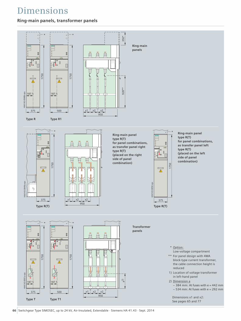
���
����
����
����
�
�� �� ��
���
����
���
��
� ��
� �
�� ��
�
� ��
���
�� ��
�
��
����
���
�
���
����
����
����
�
�� � �
���
�� �� ��
���
���
����
����
����
�
���
���
�����
����
����
���
�����
Type R(T) Type R(T)
Type R Type R1
���
����
����
����
����
���
�
66 Switchgear Type SIMOSEC, up to 24 kV, Air-Insulated, Extendable · Siemens HA 41.43 · Sept. 2014
Ring-main panels, transformer panels
Dimensions
Type T Type T1
Ring-main panel type R(T)for panel combinations, as transfer panel right type R(T) (placed on the right side of panel combination)
Ring-main panel type R(T) for panel combinations, as transfer panel left type R(T) (placed on the left side of panel combination)
Transformerpanels
* Option: Low-voltage compartment
** For panel design with 4MA block-type current transformer, the cable connection height is reduced
1) Location of voltage transformer in left-hand panel
2) Dimension a ~ 384 mm: At fuses with e = 442 mm ~ 534 mm: At fuses with e = 292 mm
Dimensions x1 and x2: See pages 65 and 77
Ring-mainpanels
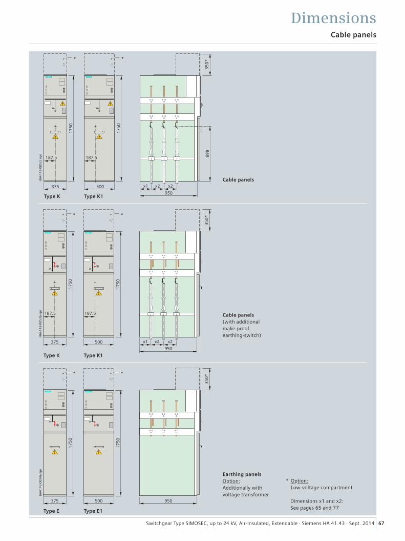
67Switchgear Type SIMOSEC, up to 24 kV, Air-Insulated, Extendable · Siemens HA 41.43 · Sept. 2014
* Option: Low-voltage compartment
Dimensions x1 and x2: See pages 65 and 77
Cable panels
Dimensions
Type K Type K1
Cable panels
Type K
Type E
Type K1
Type E1
Cable panels (with additional make-proof earthing-switch)
Earthing panels Option: Additionally with voltage transformer H
A41
43-0
094a
eps
17
50
375
*
17
50
500
*
35
0*
950
HA
4143
-005
2c e
ps
35
0*
x1 x2 x2
950
89
8
*
375 500
17
50
17
50
187.5 187.5
*
HA
4143
-005
3b e
ps
17
50
375
187.5
*
17
50
500
187.5
*
35
0*
x1 x2 x2
950
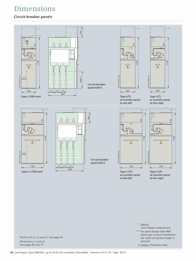
���
����
����
����
�
����
���
�
���
����
����
����
�
�
����
���
���
����
����
����
�
����
���
�
���
����
����
����
�
�
����
���
���
����
����
����
�
�
����
���
��
�� �� ��
���
� �
���
����
����
����
�
����
��� �� �� ��
���
���
��
�
��
68 Switchgear Type SIMOSEC, up to 24 kV, Air-Insulated, Extendable · Siemens HA 41.43 · Sept. 2014
Circuit-breaker panels
Dimensions
Type L (500 mm) Type L(T) as transfer panel to the left
Type L(T) as transfer panel to the right
Type L1(T) as transfer panel to the right
Type L1 (750 mm) Type L1(T) as transfer panel to the left
Circuit-breaker panel 630 A
Circuit-breaker panel 630 A
* Option: Low-voltage compartment
** For panel design with 4MA block-type current transformer, the cable connection height is reduced
∆ Option: Protection relay
Position of L1, L2 and L3: See page 65
Dimensions x1 and x2: See pages 65 and 77
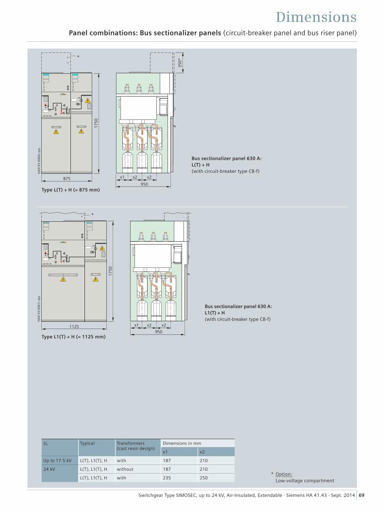
���
����
����
����
�
�� �� ��
����
���
�����
�
���
����
����
����
�
�
�� �� ��
����
���� ��
69Switchgear Type SIMOSEC, up to 24 kV, Air-Insulated, Extendable · Siemens HA 41.43 · Sept. 2014
* Option: Low-voltage compartment
Type L(T) + H (= 875 mm)
Bus sectionalizer panel 630 A: L(T) + H(with circuit-breaker type CB-f)
Type L1(T) + H (= 1125 mm)
Bus sectionalizer panel 630 A: L1(T) + H (with circuit-breaker type CB-f)
Panel combinations: Bus sectionalizer panels (circuit-breaker panel and bus riser panel)
Dimensions
Ur Typical Transformers (cast resin design)
Dimensions in mm
x1 x2
Up to 17.5 kV L(T), L1(T), H with 187 210
24 kV L(T), L1(T), H without 187 210
L(T), L1(T), H with 235 250
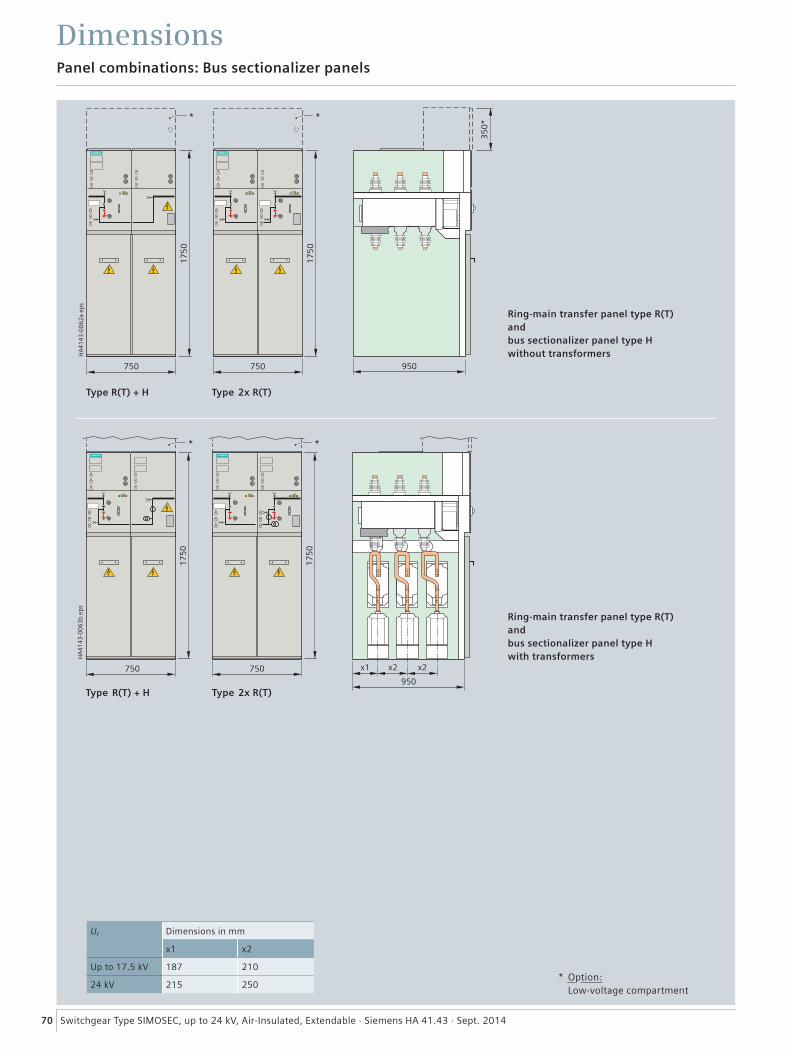
���
����
����
����
�
�� �� ��
�
����
���
�
����
��� ��
���
����
����
����
�
����
���
����
�
����
���
�
���
70 Switchgear Type SIMOSEC, up to 24 kV, Air-Insulated, Extendable · Siemens HA 41.43 · Sept. 2014
Panel combinations: Bus sectionalizer panels
Dimensions
Type R(T) + H
Type R(T) + H
Type 2x R(T)
Type 2x R(T)
Ring-main transfer panel type R(T) and bus sectionalizer panel type Hwithout transformers
Ring-main transfer panel type R(T) and bus sectionalizer panel type Hwith transformers
* Option: Low-voltage compartment
Ur Dimensions in mm
x1 x2
Up to 17.5 kV 187 210
24 kV 215 250
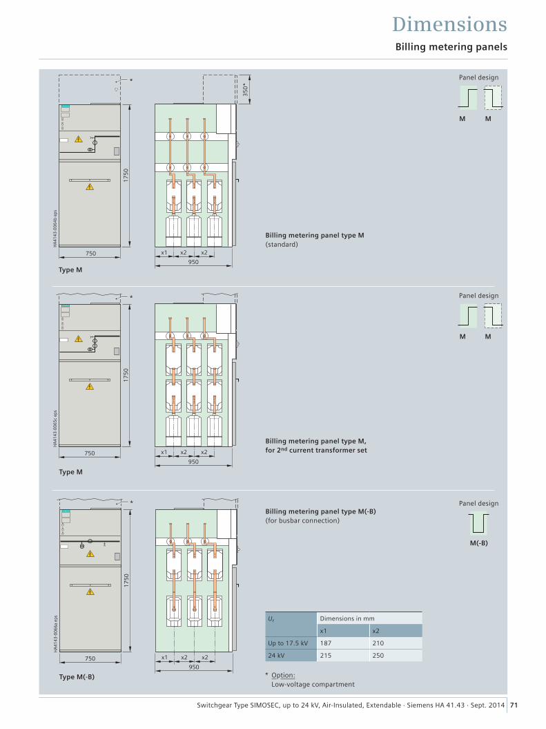
���
����
����
����
�
����
������
����
�
�� � �
���
����
����
����
�
�
����
������
�� � �
71Switchgear Type SIMOSEC, up to 24 kV, Air-Insulated, Extendable · Siemens HA 41.43 · Sept. 2014
Dimensions
Type M
M M
M M
M(-B)
Billing metering panel type M (standard)
Billing metering panels
Panel design
Type M
Billing metering panel type M, for 2nd current transformer set
Panel design
���
����
����
����
�
�
����
������
�� � �
Type M(-B)
Billing metering panel type M(-B) (for busbar connection)
Panel design
* Option: Low-voltage compartment
Ur Dimensions in mm
x1 x2
Up to 17.5 kV 187 210
24 kV 215 250
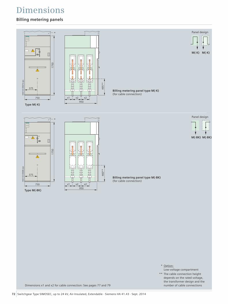
72 Switchgear Type SIMOSEC, up to 24 kV, Air-Insulated, Extendable · Siemens HA 41.43 · Sept. 2014
Billing metering panels
Dimensions
Billing metering panel type M(-K) (for cable connection)
Panel design
Panel design
Type M(-K)
M(-K) M(-K)
M(-BK) M(-BK)
Type M(-BK)
Billing metering panel type M(-BK) (for cable connection)
Dimensions x1 and x2 for cable connection: See pages 77 and 79
* Option: Low-voltage compartment
** The cable connection height depends on the rated voltage, the transformer design and the number of cable connections
���
����
����
����
�
���
�
����
���
���
�� �
����
�
�
���
����
����
����
�
���
�
����
���
���
� �
����
�
�
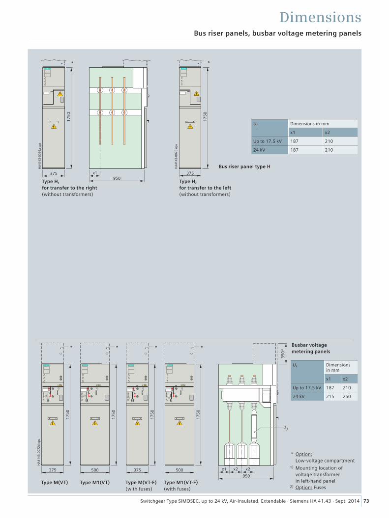
73Switchgear Type SIMOSEC, up to 24 kV, Air-Insulated, Extendable · Siemens HA 41.43 · Sept. 2014
Bus riser panels, busbar voltage metering panels
Dimensions
Type M(VT) Type M1(VT) Type M(VT-F) (with fuses)
Type M1(VT-F) (with fuses)
���
����
����
����
�
���
��
������
��
Type H, for transfer to the left (without transformers)
Bus riser panel type H ���
����
����
����
�
����
���
Type H, for transfer to the right (without transformers)
Ur Dimensions in mm
x1 x2
Up to 17.5 kV 187 210
24 kV 187 210
17
50
375950
17
50
500
*
35
0**
17
50
375
*
HA
4143
-007
2d e
ps
2)
x1 x2 x2
17
50
500
*
* Option: Low-voltage compartment 1) Mounting location of voltage transformer in left-hand panel 2) Option: Fuses
Busbar voltage metering panels
Ur Dimensions in mm
x1 x2
Up to 17.5 kV 187 210
24 kV 215 250
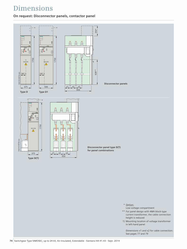
74 Switchgear Type SIMOSEC, up to 24 kV, Air-Insulated, Extendable · Siemens HA 41.43 · Sept. 2014
On request: Disconnector panels, contactor panel
Dimensions���
����
����
����
�
�� �� ��
���
���
��
�
����
���
�����
����
���
�����
��
����
���
�
���
����
����
����
�
���
�� � �
Type D
Type D(T)
Type D1
Disconnector panel type D(T)for panel combinations
Disconnector panels
* Option: Low-voltage compartment
** For panel design with 4MA block-type current transformer, the cable connection height is reduced
1) Mounting location of voltage transformer in left-hand panel
Dimensions x1 and x2 for cable connection: See pages 77 and 79
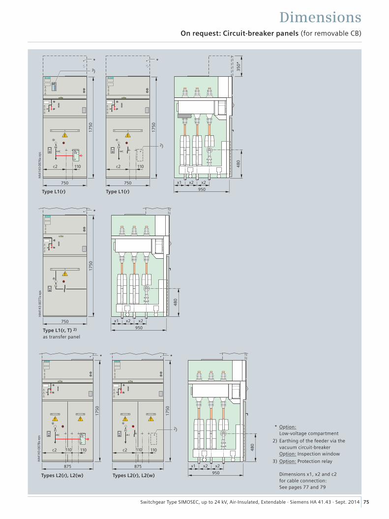
75Switchgear Type SIMOSEC, up to 24 kV, Air-Insulated, Extendable · Siemens HA 41.43 · Sept. 2014
On request: Circuit-breaker panels (for removable CB)
Dimensions���
����
����
����
�
����
���
�
����
���
����� �������� ���
�
� � �
���
���
��
Types L2(r), L2(w)
���
����
����
����
�
�� �� ��
���
� �
����
����
���
�
����
���
�
����� �����
�
�
���
����
����
����
�
����
���
�
�� �� ��
���
� �
Type L1(r, T) 2) as transfer panel
Type L1(r)
* Option: Low-voltage compartment
2) Earthing of the feeder via the vacuum circuit-breaker Option: Inspection window
3) Option: Protection relay
Dimensions x1, x2 and c2 for cable connection: See pages 77 and 79
Type L1(r)
Types L2(r), L2(w)
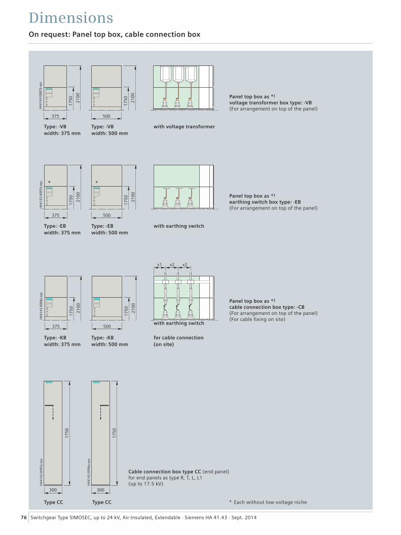
76 Switchgear Type SIMOSEC, up to 24 kV, Air-Insulated, Extendable · Siemens HA 41.43 · Sept. 2014
On request: Panel top box, cable connection box
Dimensions���
����
����
����
�
����
���
����
����
���
����
Type: -VB width: 375 mm
Type: -VB width: 500 mm
with voltage transformer
with earthing switch
for cable connection (on site)
with earthing switch
Panel top box as *) voltage transformer box type: -VB (For arrangement on top of the panel)
���
����
����
����
�
����
���
����
����
���
����
���
����
����
����
�
����
���
����
����
���
����
�� �� ��
Type: -EB width: 375 mm
Type: -KB width: 375 mm
Type: -EB width: 500 mm
Type: -KB width: 500 mm
Panel top box as *) earthing switch box type: -EB (For arrangement on top of the panel)
Panel top box as *) cable connection box type: -CB (For arrangement on top of the panel) (For cable fixing on site)
���
����
����
����
�
����
���
���
����
����
����
�
����
���
Type CC Type CC
Cable connection box type CC (end panel) for end panels as type R, T, L, L1 (up to 17.5 kV)
* Each without low-voltage niche
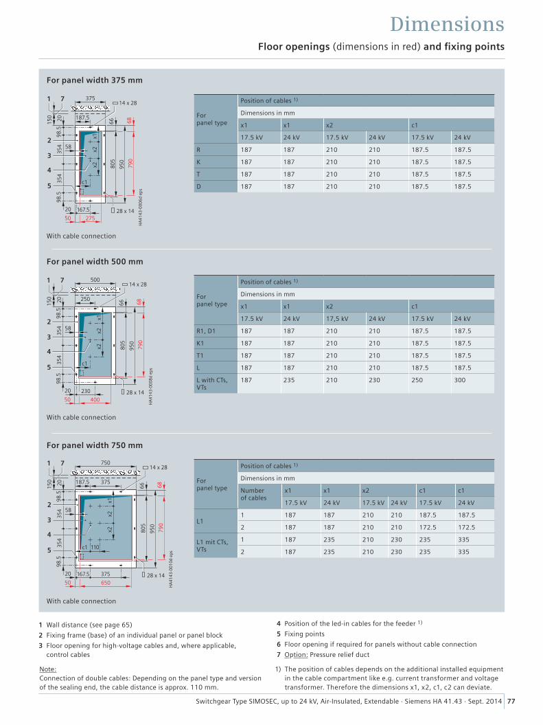
77Switchgear Type SIMOSEC, up to 24 kV, Air-Insulated, Extendable · Siemens HA 41.43 · Sept. 2014
4 Position of the led-in cables for the feeder 1)
5 Fixing points
6 Floor opening if required for panels without cable connection
7 Option: Pressure relief duct
Note: Connection of double cables: Depending on the panel type and version of the sealing end, the cable distance is approx. 110 mm.
1 Wall distance (see page 65)
2 Fixing frame (base) of an individual panel or panel block
3 Floor opening for high-voltage cables and, where applicable, control cables
DimensionsFloor openings (dimensions in red) and fixing points
1) The position of cables depends on the additional installed equipment in the cable compartment like e.g. current transformer and voltage transformer. Therefore the dimensions x1, x2, c1, c2 can deviate.
���
����
����
����
�
�������
�����
��
���
��
�
� ���
���
�� ���
������
� �����
���
� ���
����
�
��
���
��
��
� ��
�
�
�
�
� �
���
����
����
����
�
�����
��
���
���
���
��
��
���
���
�� ���
�������
�������
��
������
����
�
����
����
��
���
�
�
�
�
��
���
����
����
����
�
���
�������
��
���
��
���
��
�
� ���
���
�� ���
������
� �����
���
� ���
����
�
����
� ��
���
��
���
���
�
�
�
�
� �
For panel width 375 mm
For panel width 500 mm
For panel width 750 mm
With cable connection
With cable connection
With cable connection
For panel type
Position of cables 1)
Dimensions in mm
x1 x1 x2 c1
17.5 kV 24 kV 17.5 kV 24 kV 17.5 kV 24 kV
R 187 187 210 210 187.5 187.5
K 187 187 210 210 187.5 187.5
T 187 187 210 210 187.5 187.5
D 187 187 210 210 187.5 187.5
For panel type
Position of cables 1)
Dimensions in mm
x1 x1 x2 c1
17.5 kV 24 kV 17,5 kV 24 kV 17.5 kV 24 kV
R1, D1 187 187 210 210 187.5 187.5
K1 187 187 210 210 187.5 187.5
T1 187 187 210 210 187.5 187.5
L 187 187 210 210 187.5 187.5
L with CTs, VTs
187 235 210 230 250 300
For panel type
Position of cables 1)
Dimensions in mm
Number of cables
x1 x1 x2 c1 c1
17.5 kV 24 kV 17.5 kV 24 kV 17.5 kV 24 kV
L11 187 187 210 210 187.5 187.5
2 187 187 210 210 172.5 172.5
L1 mit CTs, VTs
1 187 235 210 230 235 335
2 187 235 210 230 235 335

4 Position of the led-in cables for the feeder 1)
5 Fixing points
6 Floor opening if required for panels without cable connection
7 Option: Pressure relief duct
Note: Connection of double cables: Depending on the panel type and version of the sealing end, the cable distance is approx. 110 mm.
1 Wall distance (see page 65)
2 Fixing frame (base) of an individual panel or panel block
3 Floor opening for high-voltage cables and, where applicable, control cables
DimensionsFloor openings (dimensions in red) and fixing points
78 Switchgear Type SIMOSEC, up to 24 kV, Air-Insulated, Extendable · Siemens HA 41.43 · Sept. 2014
1) The position of cables depends on the additional installed equipment in the cable compartment like e.g. current transformer and voltage transformer. Therefore the dimensions x1, x2, c1, c2 can deviate.
���
����
����
����
�
������
�
�������
��
��
��
���
��
�
� ���
���
�� ���
������
� �����
���
� ���
����
�
����
� ��
���
��
���
��
���
�
�
�
�
�
���
����
����
����
�
���
�
�������
��
���
��
���
��
�
� ���
���
�� ���
������
� �����
���
� ���
����
�
����
� ��
���
��
���
��
���
�
�
�
�
�
On request: For panel type L1(r), L1(w), width 750 mm
On request: For panel type L2(r), L2(w), width 875 mm
With cable connection
With cable connection (up to 3 cables)
For panel type
Position of cables 1)
Dimensions in mm
Number of cables
x1 x1 x2 c2 c2
17.5 kV 24 kV 17.5 kV 24 kV 17.5 kV 24 kV
L1(r)1 187 235 210 230 390 390
2 187 235 210 230 390 390
L1(w)1 187 235 210 230 390 390
2 187 235 210 230 390 390
For panel type
Position of cables 1)
Dimensions in mm
Number of cables
x1 x1 x2 c2 c2
17.5 kV 24 kV 17.5 kV 24 kV 17.5 kV 24 kV
L1(r)
1 187 235 210 230 390 390
2 187 235 210 230 390 390
3 187 235 210 230 390 390
L1(w)
1 187 235 210 230 390 390
2 187 235 210 230 390 390
3 187 235 210 230 390 390
���
����
����
����
�
���
�������
��
���
��
���
��
�
� ���
���
�� ���
������
� �����
���
� ���
����
�
����
� ��
���
��
���
���
�
�
�
�
� �
For panel width 750 mm
With cable connection
For panel type
Position of cables 1)
Dimensions in mm
Number of cables
x1 x1 x2 c1 c1
17.5 kV 24 kV 17.5 kV 24 kV 17.5 kV 24 kV
M(-K) 1 187 215 210 250 375 375
M(-BK) 1 187 215 210 250 375 375
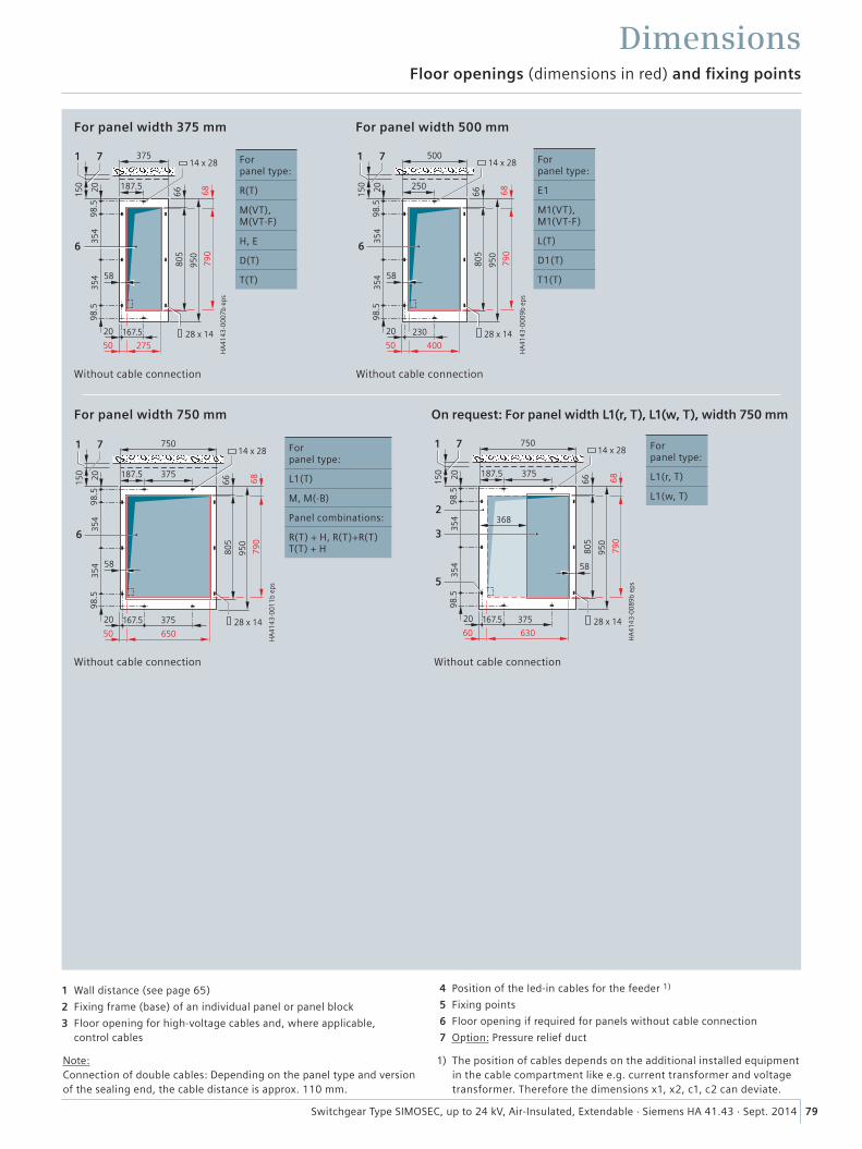
4 Position of the led-in cables for the feeder 1)
5 Fixing points
6 Floor opening if required for panels without cable connection
7 Option: Pressure relief duct
Note: Connection of double cables: Depending on the panel type and version of the sealing end, the cable distance is approx. 110 mm.
1 Wall distance (see page 65)
2 Fixing frame (base) of an individual panel or panel block
3 Floor opening for high-voltage cables and, where applicable, control cables
Dimensions
For panel width 375 mm For panel width 500 mm
Floor openings (dimensions in red) and fixing points
���
����
����
����
�
�������
���
���
��
��
��
�����
���
�� ���
�������
�������
� �
���� �
����
� �
��
���
�
��
Without cable connection
For panel type:
R(T)
M(VT), M(VT-F)
H, E
D(T)
T(T)
���
����
����
����
�
�����
���
���
���
��
��
���
���
�� ���
�������
�������
��
������
����
���
��
���
�
��
Without cable connection
For panel type:
E1
M1(VT), M1(VT-F)
L(T)
D1(T)
T1(T)���
����
����
����
�
�������
���
���
��
��
��
�����
���
�� ���
�������
�������
� �
���� �
����
� �
��
���
���
���
�
� �
Without cable connection
For panel type:
L1(T)
M, M(-B)
Panel combinations:
R(T) + H, R(T)+R(T) T(T) + H
���
����
����
����
�
�
����� �
���
���
���
��
��
�����
���
�� ���
����� �
��������
��� �
����
���
����
���
���
���
���
�
�
�
�
Without cable connection
For panel width 750 mm On request: For panel width L1(r, T), L1(w, T), width 750 mm
For panel type:
L1(r, T)
L1(w, T)
79Switchgear Type SIMOSEC, up to 24 kV, Air-Insulated, Extendable · Siemens HA 41.43 · Sept. 2014
1) The position of cables depends on the additional installed equipment in the cable compartment like e.g. current transformer and voltage transformer. Therefore the dimensions x1, x2, c1, c2 can deviate.
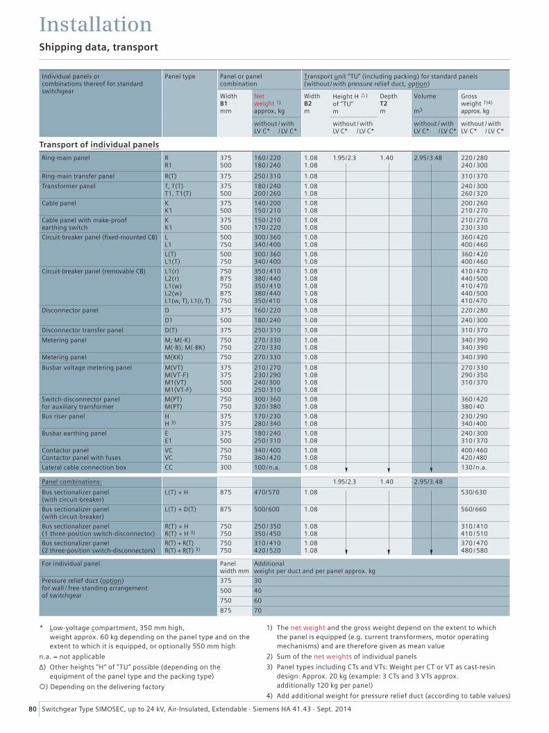
80 Switchgear Type SIMOSEC, up to 24 kV, Air-Insulated, Extendable · Siemens HA 41.43 · Sept. 2014
Individual panels or combinations thereof for standard switchgear
Panel type Panel or panel combination
Transport unit “TU” (including packing) for standard panels (without /with pressure relief duct, option)
Width B1 mm
Net weight 1) approx. kg
Width B2 m
Height H ) of “TU“ m
Depth T2 m
Volume m3
Gross weight 1)4) approx. kg
without / with LV C* / LV C*
without / with LV C* / LV C*
without / with LV C* / LV C*
without / with LV C* / LV C*
Transport of individual panels
Ring-main panel R R1
375 500
160 / 220 180 / 240
1.08 1.08
1.95 / 2.3 1.40 2.95 / 3.48 220 / 280 240 / 300
Ring-main transfer panel R(T) 375 250 / 310 1.08 310 / 370
Transformer panel T, T(T) T1, T1(T)
375 500
180 / 240 200 / 260
1.08 1.08
240 / 300 260 / 320
Cable panel K K1
375 500
140 / 200 150 / 210
1.08 1.08
200 / 260 210 / 270
Cable panel with make-proof earthing switch
K K1
375 500
150 / 210 170 / 220
1.08 1.08
210 / 270 230 / 330
Circuit-breaker panel (fixed-mounted CB) L L1
500 750
300 / 360 340 / 400
1.08 1.08
360 / 420 400 / 460
L(T) L1(T)
500 750
300 / 360 340 / 400
1.08 1.08
360 / 420 400 / 460
Circuit-breaker panel (removable CB) L1(r) L2(r) L1(w) L2(w) L1(w, T), L1(r, T)
750 875 750 875 750
350 / 410 380 / 440 350 / 410 380 / 440 350 /410
1.08 1.08 1.08 1.08 1.08
410 / 470 440 / 500 410 / 470 440 / 500 410 /470
Disconnector panel D 375 160 / 220 1.08 220 / 280
D1 500 180 / 240 1.08 240 / 300
Disconnector transfer panel D(T) 375 250 / 310 1.08 310 / 370
Metering panel M; M(-K) M(-B); M(-BK)
750 750
270 / 330 270 / 330
1.08 1.08
340 / 390 340 / 390
Metering panel M(KK) 750 270 / 330 1.08 340 / 390
Busbar voltage metering panel M(VT) M(VT-F) M1(VT) M1(VT-F)
375 375 500 500
210 / 270 230 / 290 240 /300 250 / 310
1.08 1.08 1.08 1.08
270 / 330 290 / 350 310 / 370
Switch-disconnector panel for auxiliary transformer
M(PT) M(PT)
750 750
300 / 360 320 / 380
1.08 1.08
360 / 420 380 / 40
Bus riser panel H H 3)
375 375
170 / 230 280 / 340
1.08 1.08
230 / 290 340 / 400
Busbar earthing panel E E1
375 500
180 / 240 250 / 310
1.08 1.08
240 / 300 310 / 370
Contactor panel Contactor panel with fuses
VC VC
750 750
340 / 400 360 / 420
1.08 1.08
400 / 460 420 / 480
Lateral cable connection box CC 300 100/n.a. 1.08 130/n.a.
Panel combinations: 1.95 / 2.3 1.40 2.95/3.48
Bus sectionalizer panel (with circuit-breaker)
L(T) + H 875 470/570 1.08 530/630
Bus sectionalizer panel (with circuit-breaker)
L(T) + D(T) 875 500/600 1.08 560/660
Bus sectionalizer panel (1 three-position switch-disconnector)
R(T) + H R(T) + H 3)
750 750
250 / 350 350 / 450
1.08 1.08
310 / 410 410 / 510
Bus sectionalizer panel (2 three-position switch-disconnectors)
R(T) + R(T) R(T) + R(T) 3)
750 750
310 / 410 420 / 520
1.08 1.08
370 / 470 480 / 580
For individual panel Panel width mm
Additional weight per duct and per panel approx. kg
Pressure relief duct (option) for wall / free-standing arrangement of switchgear
375 30
500 40
750 60
875 70
InstallationShipping data, transport
1) The net weight and the gross weight depend on the extent to which the panel is equipped (e.g. current transformers, motor operating mechanisms) and are therefore given as mean value
2) Sum of the net weights of individual panels
3) Panel types including CTs and VTs: Weight per CT or VT as cast-resin design: Approx. 20 kg (example: 3 CTs and 3 VTs approx. additionally 120 kg per panel)
4) Add additional weight for pressure relief duct (according to table values)
* Low-voltage compartment, 350 mm high, weight approx. 60 kg depending on the panel type and on the extent to which it is equipped, or optionally 550 mm high
n.a. = not applicable
∆) Other heights “H“ of “TU“ possible (depending on the equipment of the panel type and the packing type)
) Depending on the delivering factory
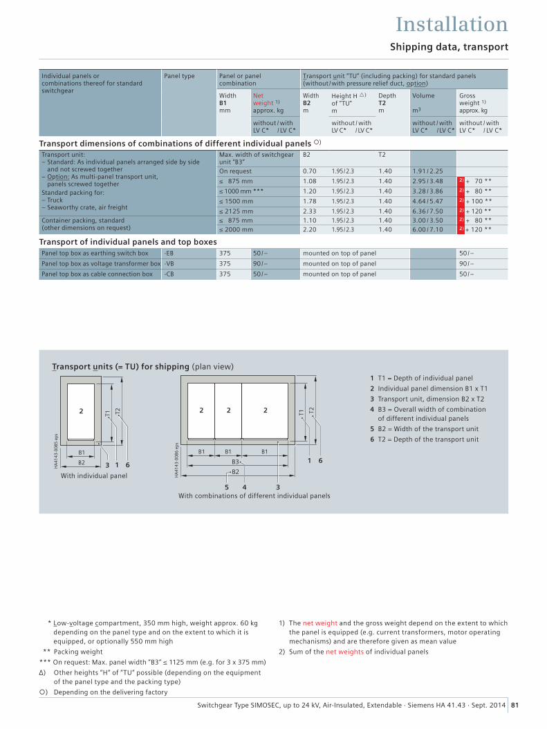
81Switchgear Type SIMOSEC, up to 24 kV, Air-Insulated, Extendable · Siemens HA 41.43 · Sept. 2014
1) The net weight and the gross weight depend on the extent to which the panel is equipped (e.g. current transformers, motor operating mechanisms) and are therefore given as mean value
2) Sum of the net weights of individual panels
* Low-voltage compartment, 350 mm high, weight approx. 60 kg depending on the panel type and on the extent to which it is equipped, or optionally 550 mm high
** Packing weight
*** On request: Max. panel width “B3“ ≤ 1125 mm (e.g. for 3 x 375 mm)
∆) Other heights “H“ of “TU“ possible (depending on the equipment of the panel type and the packing type)
) Depending on the delivering factory
Transport dimensions of combinations of different individual panels )
Transport unit: – Standard: As individual panels arranged side by side
and not screwed together– Option: As multi-panel transport unit,
panels screwed togetherStandard packing for: – Truck – Seaworthy crate, air freight
Max. width of switchgear unit “B3”
B2 T2
On request 0.70 1.95 / 2.3 1.40 1.91 / 2.25
≤ 875 mm 1.08 1.95 / 2.3 1.40 2.95 / 3.48 2) + 70 **
≤ 1000 mm *** 1.20 1.95 / 2.3 1.40 3.28 / 3.86 2) + 80 **
≤ 1500 mm 1.78 1.95 / 2.3 1.40 4.64 / 5.47 2) + 100 **
≤ 2125 mm 2.33 1.95 / 2.3 1.40 6.36 / 7.50 2) + 120 **
Container packing, standard (other dimensions on request)
≤ 875 mm 1.10 1.95 / 2.3 1.40 3.00 / 3.50 2) + 80 **
≤ 2000 mm 2.20 1.95 / 2.3 1.40 6.00 / 7.10 2) + 120 **
InstallationShipping data, transport
���
����
����
����
��
�� �
� �� ��
� �
1 T1 = Depth of individual panel
2 Individual panel dimension B1 x T1
3 Transport unit, dimension B2 x T2
4 B3 = Overall width of combination of different individual panels
5 B2 = Width of the transport unit
6 T2 = Depth of the transport unit
Transport units (= TU) for shipping (plan view)
���
����
����
����
�� ��
��
��
�� ��
��
�
�
�
��
��
�
With combinations of different individual panels
With individual panel
Transport of individual panels and top boxesPanel top box as earthing switch box -EB 375 50/– mounted on top of panel 50 /–
Panel top box as voltage transformer box -VB 375 90/– mounted on top of panel 90 /–
Panel top box as cable connection box -CB 375 50/– mounted on top of panel 50 /–
Individual panels or combinations thereof for standard switchgear
Panel type Panel or panel combination
Transport unit “TU” (including packing) for standard panels (without /with pressure relief duct, option)
Width B1 mm
Net weight 1) approx. kg
Width B2 m
Height H ) of “TU“ m
Depth T2 m
Volume m3
Gross weight 1) approx. kg
without / with LV C* / LV C*
without / with LV C* / LV C*
without / with LV C* / LV C*
without / with LV C* / LV C*
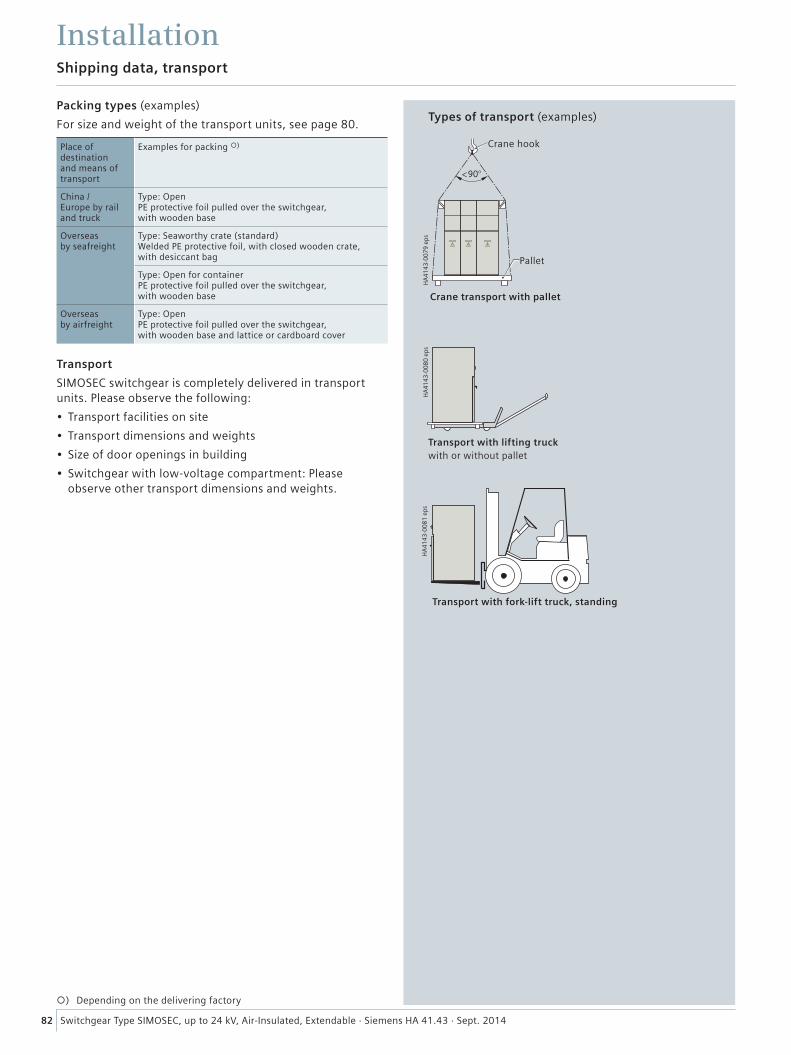
82 Switchgear Type SIMOSEC, up to 24 kV, Air-Insulated, Extendable · Siemens HA 41.43 · Sept. 2014
Shipping data, transport
Installation
Place ofdestinationand means oftransport
Examples for packing )
China /Europe by railand truck
Type: OpenPE protective foil pulled over the switchgear,with wooden base
Overseasby seafreight
Type: Seaworthy crate (standard)Welded PE protective foil, with closed wooden crate,with desiccant bag
Type: Open for containerPE protective foil pulled over the switchgear,with wooden base
Overseasby airfreight
Type: OpenPE protective foil pulled over the switchgear,with wooden base and lattice or cardboard cover
Packing types (examples)
For size and weight of the transport units, see page 80.
Transport
SIMOSEC switchgear is completely delivered in transport units. Please observe the following:
• Transport facilities on site
• Transport dimensions and weights
• Size of door openings in building
• Switchgear with low-voltage compartment: Please observe other transport dimensions and weights.
����
���
����
����
����
���
����
����
����
���
����
����
����
Types of transport (examples)
Crane hook
Pallet
Crane transport with pallet
Transport with lifting truckwith or without pallet
Transport with fork-lift truck, standing
) Depending on the delivering factory
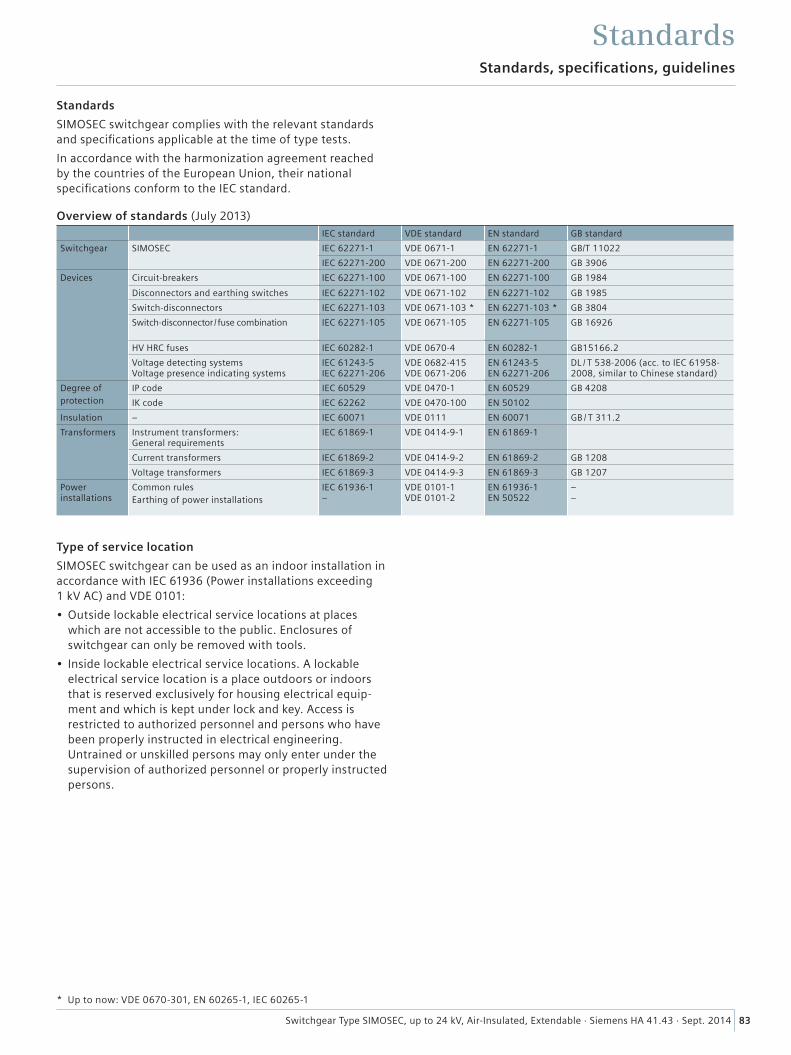
83Switchgear Type SIMOSEC, up to 24 kV, Air-Insulated, Extendable · Siemens HA 41.43 · Sept. 2014
Standards
SIMOSEC switchgear complies with the relevant standards and specifications applicable at the time of type tests.
In accordance with the harmonization agreement reached by the countries of the European Union, their national specifications conform to the IEC standard.
Type of service location
SIMOSEC switchgear can be used as an indoor installation in accordance with IEC 61936 (Power installations exceeding 1 kV AC) and VDE 0101:
• Outside lockable electrical service locations at places which are not accessible to the public. Enclosures of switchgear can only be removed with tools.
• Inside lockable electrical service locations. A lockable electrical service location is a place outdoors or indoors that is reserved exclusively for housing electrical equip-ment and which is kept under lock and key. Access is restricted to authorized personnel and persons who have been properly instructed in electrical engineering. Untrained or unskilled persons may only enter under the supervision of authorized personnel or properly instructed persons.
Standards, specifications, guidelines
Standards
* Up to now: VDE 0670-301, EN 60265-1, IEC 60265-1
Overview of standards (July 2013)IEC standard VDE standard EN standard GB standard
Switchgear SIMOSEC IEC 62271-1 VDE 0671-1 EN 62271-1 GB/T 11022
IEC 62271-200 VDE 0671-200 EN 62271-200 GB 3906
Devices Circuit-breakers IEC 62271-100 VDE 0671-100 EN 62271-100 GB 1984
Disconnectors and earthing switches IEC 62271-102 VDE 0671-102 EN 62271-102 GB 1985
Switch-disconnectors IEC 62271-103 VDE 0671-103 * EN 62271-103 * GB 3804
Switch-disconnector / fuse combination IEC 62271-105 VDE 0671-105 EN 62271-105 GB 16926
HV HRC fuses IEC 60282-1 VDE 0670-4 EN 60282-1 GB15166.2
Voltage detecting systems Voltage presence indicating systems
IEC 61243-5 IEC 62271-206
VDE 0682-415 VDE 0671-206
EN 61243-5 EN 62271-206
DL / T 538-2006 (acc. to IEC 61958- 2008, similar to Chinese standard)
Degree ofprotection
IP code IEC 60529 VDE 0470-1 EN 60529 GB 4208
IK code IEC 62262 VDE 0470-100 EN 50102
Insulation – IEC 60071 VDE 0111 EN 60071 GB / T 311.2
Transformers Instrument transformers: General requirements
IEC 61869-1 VDE 0414-9-1 EN 61869-1
Current transformers IEC 61869-2 VDE 0414-9-2 EN 61869-2 GB 1208
Voltage transformers IEC 61869-3 VDE 0414-9-3 EN 61869-3 GB 1207
Power installations
Common rulesEarthing of power installations
IEC 61936-1 –
VDE 0101-1 VDE 0101-2
EN 61936-1 EN 50522
– –
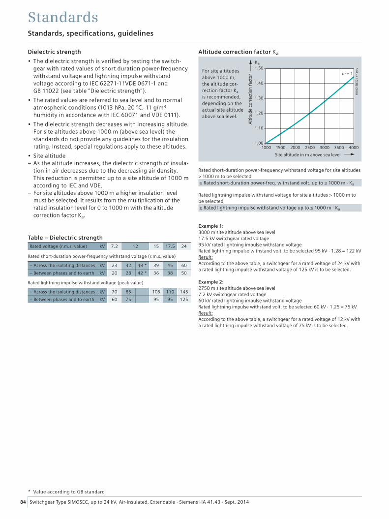
84 Switchgear Type SIMOSEC, up to 24 kV, Air-Insulated, Extendable · Siemens HA 41.43 · Sept. 2014
Table – Dielectric strengthRated voltage (r.m.s. value) kV 7.2 12 15 17.5 24
Rated short-duration power-frequency withstand voltage (r.m.s. value)
– Across the isolating distances kV 23 32 48 * 39 45 60
– Between phases and to earth kV 20 28 42 * 36 38 50 Rated lightning impulse withstand voltage (peak value)
– Across the isolating distances kV 70 85 105 110 145
– Between phases and to earth kV 60 75 95 95 125
Rated short-duration power-frequency withstand voltage for site altitudes > 1000 m to be selected ≥ Rated short-duration power-freq. withstand volt. up to ≤ 1000 m · Ka
Rated lightning impulse withstand voltage for site altitudes > 1000 m to be selected ≥ Rated lightning impulse withstand voltage up to ≤ 1000 m · Ka
Example 1:3000 m site altitude above sea level 17.5 kV switchgear rated voltage 95 kV rated lightning impulse withstand voltageRated lightning impulse withstand volt. to be selected 95 kV · 1.28 = 122 kVResult:According to the above table, a switchgear for a rated voltage of 24 kV with a rated lightning impulse withstand voltage of 125 kV is to be selected.
Example 2:2750 m site altitude above sea level 7.2 kV switchgear rated voltage 60 kV rated lightning impulse withstand voltageRated lightning impulse withstand volt. to be selected 60 kV · 1.25 = 75 kVResult:According to the above table, a switchgear for a rated voltage of 12 kV with a rated lightning impulse withstand voltage of 75 kV is to be selected.
Dielectric strength
• The dielectric strength is verified by testing the switch-gear with rated values of short duration power-frequency withstand voltage and lightning impulse withstand voltage according to IEC 62271-1 / VDE 0671-1 and GB 11022 (see table “Dielectric strength”).
• The rated values are referred to sea level and to normal atmospheric conditions (1013 hPa, 20 °C, 11 g/m3 humidity in accordance with IEC 60071 and VDE 0111).
• The dielectric strength decreases with increasing altitude. For site altitudes above 1000 m (above sea level) the standards do not provide any guidelines for the insulation rating. Instead, special regulations apply to these altitudes.
• Site altitude – As the altitude increases, the dielectric strength of insula-tion in air decreases due to the decreasing air density. This reduction is permitted up to a site altitude of 1000 m according to IEC and VDE.
– For site altitudes above 1000 m a higher insulation level must be selected. It results from the multiplication of the rated insulation level for 0 to 1000 m with the altitude correction factor Ka.
* Value according to GB standard
Altitude correction factor Ka
For site altitudes above 1000 m, the altitude cor-rection factor Ka is recommended, depending on the actual site altitude above sea level.
Standards, specifications, guidelines
Standards
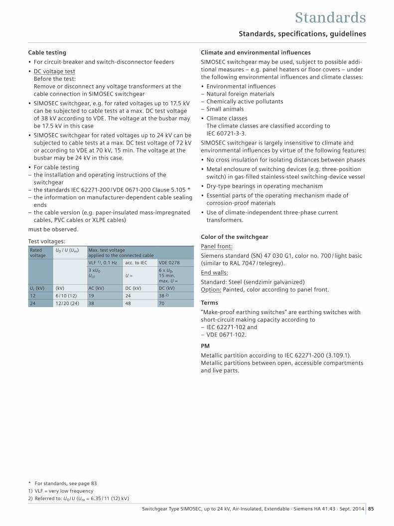
85Switchgear Type SIMOSEC, up to 24 kV, Air-Insulated, Extendable · Siemens HA 41.43 · Sept. 2014
Standards, specifications, guidelines
Standards
Cable testing
• For circuit-breaker and switch-disconnector feeders
• DC voltage test Before the test: Remove or disconnect any voltage transformers at the cable connection in SIMOSEC switchgear
• SIMOSEC switchgear, e.g. for rated voltages up to 17.5 kV can be subjected to cable tests at a max. DC test voltage of 38 kV according to VDE. The voltage at the busbar may be 17.5 kV in this case
• SIMOSEC switchgear for rated voltages up to 24 kV can be subjected to cable tests at a max. DC test voltage of 72 kV or according to VDE at 70 kV, 15 min. The voltage at the busbar may be 24 kV in this case.
• For cable testing – the installation and operating instructions of the switchgear
– the standards IEC 62271-200 / VDE 0671-200 Clause 5.105 * – the information on manufacturer-dependent cable sealing ends
– the cable version (e.g. paper-insulated mass-impregnated cables, PVC cables or XLPE cables)
must be observed.
Test voltages:Rated voltage
U0 / U (Um) Max. test voltage applied to the connected cable
VLF 1), 0.1 Hz acc. to IEC VDE 0278
3 xU0 ULF
U =
6 x U0, 15 min. max. U =
Ur (kV) (kV) AC (kV) DC (kV) DC (kV)
12 6 / 10 (12) 19 24 38 2)
24 12 /20 (24) 38 48 70
Climate and environmental influences
SIMOSEC switchgear may be used, subject to possible addi-tional measures – e.g. panel heaters or floor covers – under the following environmental influences and climate classes:
• Environmental influences – Natural foreign materials – Chemically active pollutants – Small animals
• Climate classes The climate classes are classified according to IEC 60721-3-3.
SIMOSEC switchgear is largely insensitive to climate and environmental influences by virtue of the following features:
• No cross insulation for isolating distances between phases
• Metal enclosure of switching devices (e.g. three-position switch) in gas-filled stainless-steel switching-device vessel
• Dry-type bearings in operating mechanism
• Essential parts of the operating mechanism made of corrosion-proof materials
• Use of climate-independent three-phase current transformers.
Color of the switchgear
Panel front:
Siemens standard (SN) 47 030 G1, color no. 700 / light basic (similar to RAL 7047 / telegrey).
End walls:
Standard: Steel (sendzimir galvanized) Option: Painted, color according to panel front.
Terms
“Make-proof earthing switches” are earthing switches with short-circuit making capacity according to
– IEC 62271-102 and – VDE 0671-102.
PM
Metallic partition according to IEC 62271-200 (3.109.1). Metallic partitions between open, accessible compartments and live parts.
* For standards, see page 83
1) VLF = very low frequency
2) Referred to: U0 / U (Um = 6.35 / 11 (12) kV)
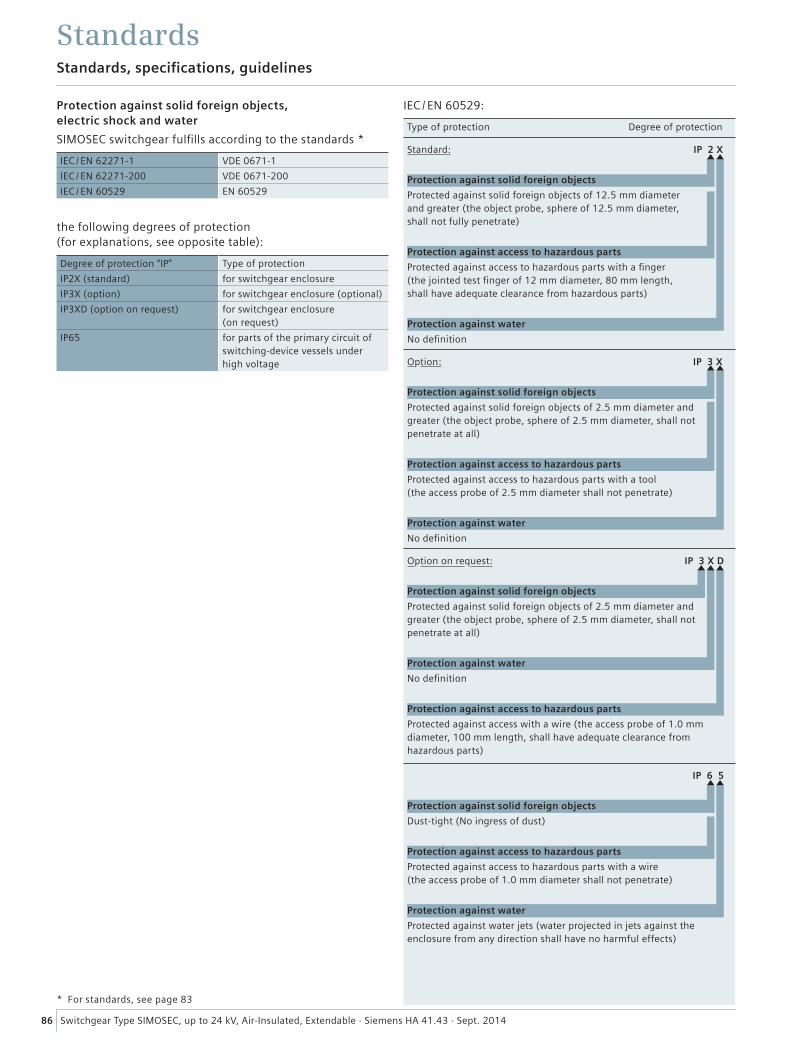
86 Switchgear Type SIMOSEC, up to 24 kV, Air-Insulated, Extendable · Siemens HA 41.43 · Sept. 2014
IEC / EN 60529:
Type of protection Degree of protection
Standard: IP 2 X
Protection against solid foreign objects
Protected against solid foreign objects of 12.5 mm diameter and greater (the object probe, sphere of 12.5 mm diameter, shall not fully penetrate)
Protection against access to hazardous parts
Protected against access to hazardous parts with a finger (the jointed test finger of 12 mm diameter, 80 mm length, shall have adequate clearance from hazardous parts)
Protection against water
No definition
Option: IP 3 X
Protection against solid foreign objects
Protected against solid foreign objects of 2.5 mm diameter and greater (the object probe, sphere of 2.5 mm diameter, shall not penetrate at all)
Protection against access to hazardous parts
Protected against access to hazardous parts with a tool (the access probe of 2.5 mm diameter shall not penetrate)
Protection against water
No definition
Option on request: IP 3 X D
Protection against solid foreign objects
Protected against solid foreign objects of 2.5 mm diameter and greater (the object probe, sphere of 2.5 mm diameter, shall not penetrate at all)
Protection against water
No definition
Protection against access to hazardous parts
Protected against access with a wire (the access probe of 1.0 mm diameter, 100 mm length, shall have adequate clearance from hazardous parts)
IP 6 5
Protection against solid foreign objects
Dust-tight (No ingress of dust)
Protection against access to hazardous parts
Protected against access to hazardous parts with a wire (the access probe of 1.0 mm diameter shall not penetrate)
Protection against water
Protected against water jets (water projected in jets against the enclosure from any direction shall have no harmful effects)
Protection against solid foreign objects, electric shock and water
SIMOSEC switchgear fulfills according to the standards *
IEC / EN 62271-1 VDE 0671-1
IEC / EN 62271-200 VDE 0671-200
IEC / EN 60529 EN 60529
the following degrees of protection (for explanations, see opposite table):
Degree of protection “IP” Type of protection
IP2X (standard) for switchgear enclosure
IP3X (option) for switchgear enclosure (optional)
IP3XD (option on request) for switchgear enclosure (on request)
IP65 for parts of the primary circuit of switching-device vessels under high voltage
* For standards, see page 83
Standards, specifications, guidelines
Standards

Siemens AG
Infrastructure & Cities Sector
Low and Medium Voltage Division
Medium Voltage & Systems
Postfach 3240
91050 Erlangen, Germany
E-Mail: [email protected]
www.siemens.com/medium-voltage-switchgear
www.siemens.com/SIMOSEC
Order No. IC1000-K1441-A431-A4-7600
SIMC-0000-44014
Printed in Germany
KG 09.14 0.0 88 De | 7400 / 59441
Subject to change without prior notice.
© 2014 Siemens. All rights reserved.
The information in this document contains general descriptions of the technical options available, which may not apply in all cases.
The required technical options should therefore be specified in the contract for the individual case.