switching connectors / moebius mc-card / rp-mcx series · pdf file 6-4 switching connectors...
TRANSCRIPT

switching connectors / Moebius Mc-card / rP-Mcx series
r199 / r299
6

www.radiall.com
6-3
CONTENTS
SWIT
CHIN
G CO
NNEC
TORS
Introduction . . . . . . . . . . . . . . . . . . . . . . . . . . . . . . . . . . . . . . . . . . . . . . . . . . . . . . . . . . . . . . . . . . . . . . . . . . . . . . . . . . . . . . . . . . . . . . . . . . . . . . . . . . . . . . . . . . . . . . . . . . . . . . . . . . . . . . . . . . . . . . . . . . . 6-4 to 6-5
MOEBIUSCharacteristics . . . . . . . . . . . . . . . . . . . . . . . . . . . . . . . . . . . . . . . . . . . . . . . . . . . . . . . . . . . . . . . . . . . . . . . . . . . . . . . . . . . . . . . . . . . . . . . . . . . . . . . . . . . . . . . . . . . . . . . . . . . . . . . . . . . . . . . . . . . . . . . . . . . . . . . . 6-6
Receptacles . . . . . . . . . . . . . . . . . . . . . . . . . . . . . . . . . . . . . . . . . . . . . . . . . . . . . . . . . . . . . . . . . . . . . . . . . . . . . . . . . . . . . . . . . . . . . . . . . . . . . . . . . . . . . . . . . . . . . . . . . . . . . . . . . . . . . . . . . . . . . . . . . . . . . . . . . . . . 6-7
Switching connectors . . . . . . . . . . . . . . . . . . . . . . . . . . . . . . . . . . . . . . . . . . . . . . . . . . . . . . . . . . . . . . . . . . . . . . . . . . . . . . . . . . . . . . . . . . . . . . . . . . . . . . . . . . . . . . . . . . . . . . . . . . . . . . . . . . . . . . . . . . . . . . . 6-7
Plugs . . . . . . . . . . . . . . . . . . . . . . . . . . . . . . . . . . . . . . . . . . . . . . . . . . . . . . . . . . . . . . . . . . . . . . . . . . . . . . . . . . . . . . . . . . . . . . . . . . . . . . . . . . . . . . . . . . . . . . . . . . . . . . . . . . . . . . . . . . . . . . . . . . . . . . . . . . . . . . . . . . . . . 6-8
Adapters . . . . . . . . . . . . . . . . . . . . . . . . . . . . . . . . . . . . . . . . . . . . . . . . . . . . . . . . . . . . . . . . . . . . . . . . . . . . . . . . . . . . . . . . . . . . . . . . . . . . . . . . . . . . . . . . . . . . . . . . . . . . . . . . . . . . . . . . . . . . . . . . . . . . . . . . . . . . . . . . . 6-8
PCB mounting pattern . . . . . . . . . . . . . . . . . . . . . . . . . . . . . . . . . . . . . . . . . . . . . . . . . . . . . . . . . . . . . . . . . . . . . . . . . . . . . . . . . . . . . . . . . . . . . . . . . . . . . . . . . . . . . . . . . . . . . . . . . . . . . . . . . . . . . . . . . . . . . . . 6-8
MC-CARDCharacteristics . . . . . . . . . . . . . . . . . . . . . . . . . . . . . . . . . . . . . . . . . . . . . . . . . . . . . . . . . . . . . . . . . . . . . . . . . . . . . . . . . . . . . . . . . . . . . . . . . . . . . . . . . . . . . . . . . . . . . . . . . . . . . . . . . . . . . . . . . . . . . . . . . . . . . . . . 6-9
Plugs . . . . . . . . . . . . . . . . . . . . . . . . . . . . . . . . . . . . . . . . . . . . . . . . . . . . . . . . . . . . . . . . . . . . . . . . . . . . . . . . . . . . . . . . . . . . . . . . . . . . . . . . . . . . . . . . . . . . . . . . . . . . . . . . . . . . . . . . . . . . . . . . . . . . . . . . . . . . . . . . . . . . 6-10
SMT Receptacle . . . . . . . . . . . . . . . . . . . . . . . . . . . . . . . . . . . . . . . . . . . . . . . . . . . . . . . . . . . . . . . . . . . . . . . . . . . . . . . . . . . . . . . . . . . . . . . . . . . . . . . . . . . . . . . . . . . . . . . . . . . . . . . . . . . . . . . . . . . . . . . . . . . . . . 6-10
Switches . . . . . . . . . . . . . . . . . . . . . . . . . . . . . . . . . . . . . . . . . . . . . . . . . . . . . . . . . . . . . . . . . . . . . . . . . . . . . . . . . . . . . . . . . . . . . . . . . . . . . . . . . . . . . . . . . . . . . . . . . . . . . . . . . . . . . . . . . . . . . . . . . . . . . . . . . . . . . . . 6-10
Adapters . . . . . . . . . . . . . . . . . . . . . . . . . . . . . . . . . . . . . . . . . . . . . . . . . . . . . . . . . . . . . . . . . . . . . . . . . . . . . . . . . . . . . . . . . . . . . . . . . . . . . . . . . . . . . . . . . . . . . . . . . . . . . . . . . . . . . . . . . . . . . . . . . . . . . . . . . . . . . . . . 6-11
Receptacle . . . . . . . . . . . . . . . . . . . . . . . . . . . . . . . . . . . . . . . . . . . . . . . . . . . . . . . . . . . . . . . . . . . . . . . . . . . . . . . . . . . . . . . . . . . . . . . . . . . . . . . . . . . . . . . . . . . . . . . . . . . . . . . . . . . . . . . . . . . . . . . . . . . . . . . . . . . . . 6-11
Assembly instructions . . . . . . . . . . . . . . . . . . . . . . . . . . . . . . . . . . . . . . . . . . . . . . . . . . . . . . . . . . . . . . . . . . . . . . . . . . . . . . . . . . . . . . . . . . . . . . . . . . . . . . . . . . . . . . . . . . . . . . . . . . . . . . . . . . . . . . . . . . . . . . 6-12
RP-MCXInterface . . . . . . . . . . . . . . . . . . . . . . . . . . . . . . . . . . . . . . . . . . . . . . . . . . . . . . . . . . . . . . . . . . . . . . . . . . . . . . . . . . . . . . . . . . . . . . . . . . . . . . . . . . . . . . . . . . . . . . . . . . . . . . . . . . . . . . . . . . . . . . . . . . . . . . . . . . . . . . . . 6-13
Receptacles . . . . . . . . . . . . . . . . . . . . . . . . . . . . . . . . . . . . . . . . . . . . . . . . . . . . . . . . . . . . . . . . . . . . . . . . . . . . . . . . . . . . . . . . . . . . . . . . . . . . . . . . . . . . . . . . . . . . . . . . . . . . . . . . . . . . . . . . . . . . . . . . . . . . . . . . . . . . 6-13
RF power switching connectorsQMA type . . . . . . . . . . . . . . . . . . . . . . . . . . . . . . . . . . . . . . . . . . . . . . . . . . . . . . . . . . . . . . . . . . . . . . . . . . . . . . . . . . . . . . . . . . . . . . . . . . . . . . . . . . . . . . . . . . . . . . . . . . . . . . . . . . . . . . . . . . . . . . . . . . . . . . . . . . . . . . . 6-14
N type . . . . . . . . . . . . . . . . . . . . . . . . . . . . . . . . . . . . . . . . . . . . . . . . . . . . . . . . . . . . . . . . . . . . . . . . . . . . . . . . . . . . . . . . . . . . . . . . . . . . . . . . . . . . . . . . . . . . . . . . . . . . . . . . . . . . . . . . . . . . . . . . . . . . . . . . . . . . . . . . . . . 6-15
SMA type . . . . . . . . . . . . . . . . . . . . . . . . . . . . . . . . . . . . . . . . . . . . . . . . . . . . . . . . . . . . . . . . . . . . . . . . . . . . . . . . . . . . . . . . . . . . . . . . . . . . . . . . . . . . . . . . . . . . . . . . . . . . . . . . . . . . . . . . . . . . . . . . . . . . . . . . . . . . . . . . 6-16
QN type . . . . . . . . . . . . . . . . . . . . . . . . . . . . . . . . . . . . . . . . . . . . . . . . . . . . . . . . . . . . . . . . . . . . . . . . . . . . . . . . . . . . . . . . . . . . . . . . . . . . . . . . . . . . . . . . . . . . . . . . . . . . . . . . . . . . . . . . . . . . . . . . . . . . . . . . . . . . . . . . . . 6-17
TNC type . . . . . . . . . . . . . . . . . . . . . . . . . . . . . . . . . . . . . . . . . . . . . . . . . . . . . . . . . . . . . . . . . . . . . . . . . . . . . . . . . . . . . . . . . . . . . . . . . . . . . . . . . . . . . . . . . . . . . . . . . . . . . . . . . . . . . . . . . . . . . . . . . . . . . . . . . . . . . . . . 6-18
Pages

www.radiall.com
6-4
SWIT
CHIN
G CO
NNEC
TORS INTRODUCTION
Radiall offers a complete range of switching connectors that consists of four families: Microminiature, Moebius, for high life cycle mobile applications Microminiature, MC-Card, for mobile applications Reverse polarity MCX Power, for infrastructure applications
Microminiature Moebius: Designed for lifeWe chose Moebius in reference to the Möbius strip as the origin of the infinity symbol. A Möbius band (or strip) is an intriguing shape having a continuous looped surface with ONLY ONE SIDE and ONE EDGE. A strip with a non-orientable surface. The Moebius interface is designed to be used as an antenna connection for handheld and mobile computing devices. The switching connector provides high RF performance and it is extremely durable and reliable as a snap-on connection.
Microminiature MC-CardThe MC-Card series are micro miniature, 50Ω connectors that feature snap-on mating and a frequency range of –8 GHz.The MC-Card series was designed by Radiall in the 90's. With the success of the switching version, it made the MC-Card an excellent alternative to MMCX connectors for numerous wireless and telecom applications.In addition, the MC-Card series offer the similar performance as the MMCX by featuring quick snap-on mating and unmating withstanding a minimum of 5,000 mating cycles.
The globally adopted switching connector version consists in a female edge card receptacle with an integrated switch for SMT assembly. It allows for automatic switching between two RF signal paths. This connector is mainly used for wireless PCMCIA-Cards or GPS devices to switch between the internal antenna and a higher-gain external antenna. In addition to the standard MC-Card series, Radiall also offers a 3mm dia. MC-Card. With this version, wireless equipment can be differentiated and protected against wrong antenna connections.
APPLICATIONSWireless communication (Bluetooth, WLAN, WiFi, WiMax, ZigBee).
Handheld, Notebook, PCMCIA Card, Express Card, PDA, GPS, and any low power wireless equipment requiring transmission re-direction.
www.radiall.com
6-5
SWIT
CHIN
G CO
NNEC
TORSINTRODUCTION
Reverse Polarity MCXA range of reverse polarity MCX connectors is available for handheld devices. Additional standard or reverse polarity switching connectors can be developed upon request.
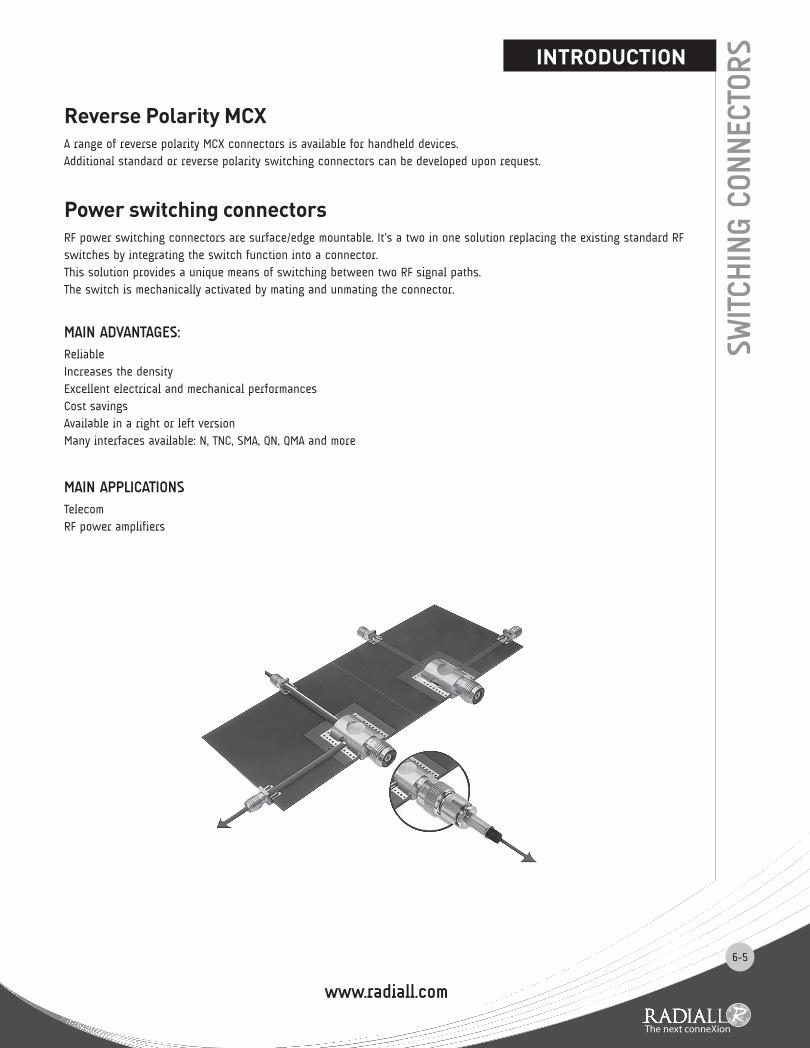
Power switching connectorsRF power switching connectors are surface/edge mountable. It’s a two in one solution replacing the existing standard RF switches by integrating the switch function into a connector. This solution provides a unique means of switching between two RF signal paths. The switch is mechanically activated by mating and unmating the connector.
MAIN ADvANTAGES:Reliable Increases the density Excellent electrical and mechanical performances Cost savings Available in a right or left version Many interfaces available: N, TNC, SMA, QN, QMA and more
MAIN APPLICATIONSTelecom RF power amplifiers

www.radiall.com
6-6
Not mated MatedOperating temperature range -40°C to + 110°C Rated power 10 W / 900 MHzDC Current Withstanding 1 A maxFrequency range DC to 6 GHz
V.S.W.R. 1.20 max DC to 3 GHz 1.50 max 3 to 6 GHz
1.15 max DC to 3 GHz 1.25 max 3 GHz to 6 GHz
Insertion loss 0.15 dB max DC to 2 GHz
0.20 dB max 2 GHz to 3 GHz 0.40 dB max 3 GHz to 6 GHz
0.10 dB max DC to 2 GHz 0.15 dB max 2 GHz to 3 GHz 0.20 dB max 3 GHz to 6 GHz
Isolation loss---
35 dB minDC to 1 GHz 25 dB min 1 GHz to 3 GHz 25 dB min 3 GHz to 6 GHz
Item Specification Conditions Contact resistance 200 mΩ max 100 mA Insulation resistance 3000 MΩ min 250 V DC
Withstanding voltage No flashover or insulation breakdown 250 V rms
Vibration No discontinuities > 1µs under 100mA
Sinus: 5-500Hz / displacement 0.75 peak / acceleration 10 g duration 2h in each direction
Random: 5-1000Hz / displacement 0.75 peak / acceleration 3.3 g duration 1h in each direction 25 dB min 3 GHz to 6 GHz
Shock No discontinuities > 1µs under 100mA
Acceleration 50 g / duration pulse 11 ms / waveform pulse half sinus / number
of shocks 3 per direction
Free fallCenter contact resistance
RF measurements No discontinuities > 1 ms under 100mA
NFC 20732 method 1 Test area concrete / fall height 1 m / duration 2*2 falls
Temperature life Center contact resistance RF measurements T + 90°C / duration 1000 h / 40% HR
Thermal shock Center contact resistance RF measurements
T - 40°C to + 90°C Exposure 15mn / transfert time < 10 s / 100 cycles
Damp heat Center contact resistance RF measurements 40°C / 93% / 21 days
Retention Force Insertion Force - mating Extraction Force - unmating
9N 12N
Initial
DurabilityMating – unmating force
Center contact resistance RF measurements
25.000 cycles
MATERIALS AND PLATINg Material Plating
Body Brass NPGR Center contact Brass NPGR Outer contact Brass NPGR Insulator PTFE / ncOthers parts Beryllium copper NPGR
MOE
BIUS CHARACTERISTICS

6-7
RECEPTACLE
SWITCHINg CONNECTOR
Part number Packaging RoHSR199 006 413 100 pieces/reel yes
Part number Packaging RoHSR199 006 813 100 pieces/reel yes
MOE
BIUS
To download data sheets and assembly instructions, visit www.radiall.com & enter the part number in the Search box.Bold part numbers represent products typically in stock & available for immediate shipment.See page 8 and 9 for packaging information.
RECEPTACLE AND SWITCHINg CONNECTOR

6-8
MOE
BIUS PLUgS, ADAPTER
PCb PATTERN
To download data sheets and assembly instructions, visit www.radiall.com & enter the part number in the Search box.Bold part numbers represent products typically in stock & available for immediate shipment.
See page 8 and 9 for packaging information.
STRAIgHT AND RIgHT ANgLE PLUgS
SMA ADAPTER
Fig. 1 Fig. 2
Fig. 3 Fig. 4
Cable group Cable group dia. Part number Fig. Packaging RoHS
RG178/RG196 2/50/S R199 006 203 1
100/Box yesR199 006 213 2
RG174/RG316 2.6/50/S R199 006 263 3R199 006 273 4
Part number Packaging RoHSR191 857 000 Unit yes
Receptacles Switching Connectors
P01
www.radiall.com
6-9
MC-
CARDCHARACTERISTICS
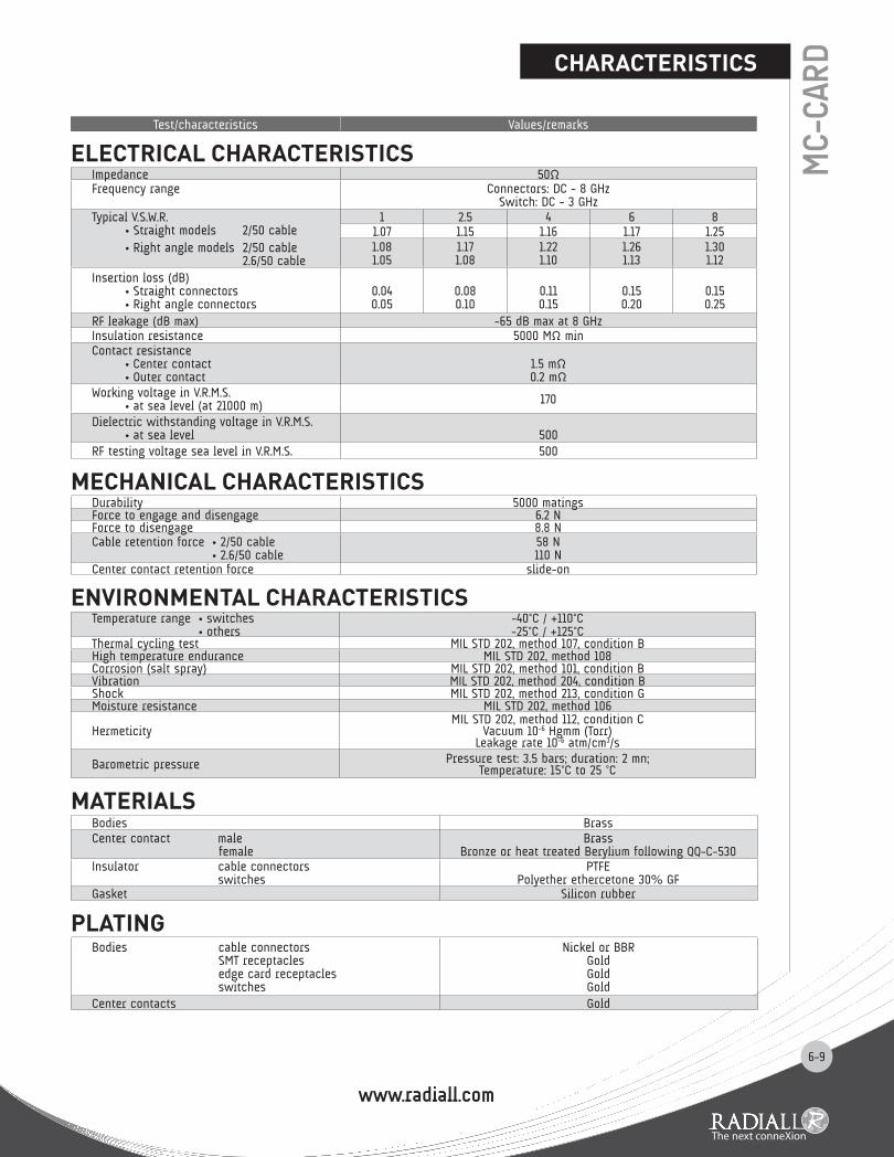
ELECTRICAL CHARACTERISTICS Impedance 50ΩFrequency range Connectors: DC - 8 GHz
Switch: DC - 3 GHzTypical V.S.W.R.
• Straight models 2/50 cable• Right angle models 2/50 cable
2.6/50 cable
1 2.5 4 6 81.07 1.15 1.16 1.17 1.251.081.05
1.171.08
1.221.10
1.261.13
1.301.12
Insertion loss (dB)• Straight connectors• Right angle connectors
0.040.05
0.080.10
0.110.15
0.150.20
0.150.25
RF leakage (dB max) -65 dB max at 8 GHzInsulation resistance 5000 MΩ minContact resistance
• Center contact• Outer contact
1.5 mΩ0.2 mΩ
Working voltage in V.R.M.S.• at sea level (at 21000 m) 170
Dielectric withstanding voltage in V.R.M.S.• at sea level 500
RF testing voltage sea level in V.R.M.S. 500
MECHANICAL CHARACTERISTICSDurability 5000 matingsForce to engage and disengage 6.2 NForce to disengage 8.8 NCable retention force • 2/50 cable
• 2.6/50 cable58 N110 N
Center contact retention force slide-on
ENVIRONMENTAL CHARACTERISTICS Temperature range • switches
• others-40°C / +110°C-25°C / +125°C
Thermal cycling test MIL STD 202, method 107, condition BHigh temperature endurance MIL STD 202, method 108Corrosion (salt spray) MIL STD 202, method 101, condition BVibration MIL STD 202, method 204, condition BShock MIL STD 202, method 213, condition GMoisture resistance MIL STD 202, method 106
HermeticityMIL STD 202, method 112, condition C
Vacuum 10-6 Hgmm (Torr)Leakage rate 10-6 atm/cm3/s
Barometric pressure Pressure test: 3.5 bars; duration: 2 mn;Temperature: 15°C to 25 °C
MATERIALSBodies Brass Center contact male female
BrassBronze or heat treated Berylium following QQ-C-530
Insulator cable connectors switches
PTFE Polyether ethercetone 30% GF
Gasket Silicon rubber
PLATINgBodies cable connectors
SMT receptacles edge card receptacles switches
Nickel or BBRGold Gold Gold
Center contacts Gold
Test/characteristics Values/remarks

6-10
RIgHT ANgLE PLUgS
Cable group Cable group dia. Part number Fig. Captive center
contact Finish Note Packaging
RG178/RG196 2/50/S R199 005 200 1no nickel crimp type 100 pieces
RG174/RG316 2.6/50/S R199 005 010 2
Cable group Cable group dia. Part number Dimensions (mm) Captive center
contact Finish Note Packaging
RG178/RG196 2/50/S R199 005 240 2.57 0.96yes nickel crimp type 100 pieces
RG174/RG316 2.6/50/S R199 005 250 3.25 1.63
Fig. 1 Fig. 2
MC-
CARD PLUgS, SMT RECEPTACLE AND SWITCHES
To download data sheets and assembly instructions, visit www.radiall.com & enter the part number in the Search box.Bold part numbers represent products typically in stock & available for immediate shipment.
See page 8 and 9 for packaging information.
Part number Fig. Captive center contact Assembly instructions PCB pattern Finish Packaging
R199 005 800 1yes
M01 P02gold
400 pieces/reelR199 005 523 2 1 piece
Part number Fig Dimension A (mm)
Captive center contact
Assembly instructions
PCB pattern Finish Packaging Note
R199 005 890 1yes M01 P01 Gold 500 pieces/reel
R299 794 800* 2 0.93 MC-CARD 3mm dia.
Electrical diagram on "M01"*Specific 3 mm interface = not compatible with standard interface plug
Fig. 1 Fig. 2
STRAIgHT PLUgS
SMT SWITCHES
Fig. 1
SMT RECEPTACLE
Fig. 2

6-11
MC-
CARDADAPTERS
To download data sheets and assembly instructions, visit www.radiall.com & enter the part number in the Search box.Bold part numbers represent products typically in stock & available for immediate shipment.See page 8 and 9 for packaging information.
Part number Fig. Series Body and finishR191 366 071 1 SMA female / MC CARD male
passivated stainless steelR191 366 091 2 SMA female / MC CARD female
bETWEEN SERIES ADAPTERS
Fig. 1 Fig. 2
Part number
R199 005 890R299 794 800
VIEW A
Part number
R199 005 800
RECEPTACLE PACkAgINg
ACCORDING TO IEC 286-3 STANDARDMATERIALS Reel: polyester Carrier tape: antistatic PETG (polyester) Cover tape: polyester
www.radiall.com
6-12
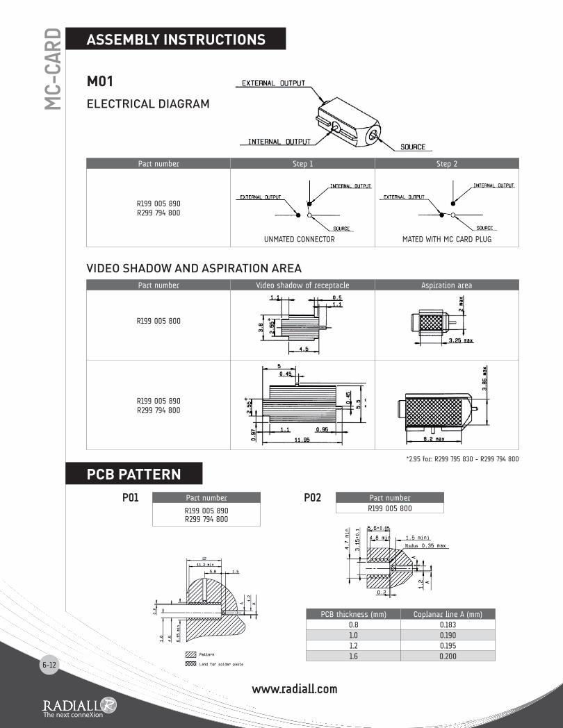
ElECTRICAl DIAGRAmMC-
CARD ASSEMbLY INSTRUCTIONS
PCb PATTERN
M01
Part number Step 1 Step 2
R199 005 890R299 794 800
UNMATED CONNECTOR MATED WITH MC CARD PLUG
Part number
R199 005 890R299 794 800
Part numberR199 005 800
PCB thickness (mm) Coplanar line A (mm)0.8 0.1831.0 0.1901.2 0.1951.6 0.200
VIDEO ShADOW AND ASpIRATION AREAPart number Video shadow of receptacle Aspiration area
R199 005 800
R199 005 890R299 794 800
*2.95 for: R299 795 830 - R299 794 800
P01 P02

6-13
RP-M
CXINTERFACE
SMT SWITCHES
Part number Fig. Packaging Note
R299 137 8001
Reel of 200R299 137 801 Reel of 900R299 142 822 2 Reel of 100 compact version
Fig. 1 Fig. 2
JACkPLUg
Letter mm inch min. max. min. max.
A DIA 0.1 3.20 .124 .126B DIA 0.48 2.84 .108 .112C DIA 3.42 0.60 .0205 .0235D DIA 3.80 0E DIA 3.60 1.40 .045 .055
F 4.00 0.41 .014 .016G 0.75 3.68 .139 .145H 0J 0 18° 22° 18° 22° 43° 47° 43° 47°
Letter mm inch min. max. min. max.
A DIA 3.80 .150B DIA 3.60 .142C DIA 3.00 .118D DIA 3.40 .134
E 0 0 .004F 0 0 .008G 2.60 .110H 4.15 .163
To download data sheets and assembly instructions, visit www.radiall.com & enter the part number in the Search box.Bold part numbers represent products typically in stock & available for immediate shipment.See page 8 and 9 for packaging information.

6-14
RF P
OWER
SW
ITCH
ING
CONNEC
TORS
ELECTRICAL CHARACTERISTICS QMA
Impedance 50ΩFrequency range DC - 3 GHzTypical V.S.W.R. 1.1 + 0.1000 x F (GHz) Maxi
Isolation at • DC to 1 GHz • 1 to 2 GHz • 2 to 3 GHz
-47 dB typical -43 dB typical -40 dB typical
Insertion Loss at • DC to 1 GHz • 1 to 2 GHz • 2 to 3 GHz
0.1 dB maxi 0.15 dB maxi 0.2 dB maxi
RF leakage NAVoltage rating 300 Veff maxiDielectric withstanting voltage 500 Veff miniInsulation resistance 5000 MΩ miniPower withstanding 110 W (at 2 GHz)
Test/characteristics Values/remarks
QMA RF POWER SWITCHINg CONNECTORS
Part number TypeR123 422 801 right
QMA TYPE
To download data sheets and assembly instructions, visit www.radiall.com & enter the part number in the Search box.Bold part numbers represent products typically in stock & available for immediate shipment.
See page 8 and 9 for packaging information.
m1 freq=1.0 GHz VSWR = 1.087 m2 freq =2.0 GH z VSWR = 1.165 m3 freq =3.0 GH z VSWR = 1.275
m1 freq= 1.0 GH z VSWR = 1.048 m2 freq=2.0 GHz VSWR = 1.070 m3 freq=3.0 GHz VSWR = 1.137

6-15
RF P
OWER
SW
ITCH
ING
CONNEC
TORSN RF POWER SWITCHINg CONNECTORS
To download data sheets and assembly instructions, visit www.radiall.com & enter the part number in the Search box.Bold part numbers represent products typically in stock & available for immediate shipment.See page 8 and 9 for packaging information.
ELECTRICAL CHARACTERISTICS N
Impedance 50ΩFrequency range DC - 3 GHzTypical V.S.W.R. 1.1 + 0.1000 x F (GHz) Maxi
Isolation at • DC to 1 GHz • 1 to 2 GHz • 2 to 3 GHz
-47 dB typical -43 dB typical -40 dB typical
Insertion Loss at • DC to 1 GHz • 1 to 2 GHz • 2 to 3 GHz
0.1 dB maxi 0.15 dB maxi 0.2 dB maxi
RF leakage NAVoltage rating 300 Veff maxiDielectric withstanting voltage 500 Veff miniInsulation resistance 5000 MΩ miniPower withstanding 100 W (at 0.9 GHz and 1.8 GHz)
Test/characteristics Values/remarks
m1 freq=1. 0 GHz VSWR = 1.084 m2 freq= 2.0 GH z VSWR= 1.097 m3 freq= 3.0 GH z V SWR= 1.212 m4 freq= 0.52 GHz VSWR= 1.054
m1 freq=1. 0 GHz VSWR = 1.027 m2 freq= 2.0 GHz VSWR = 1.043
m3 freq= 3.0 GHz VSWR = 1.137 m4 freq= 1.6 GHz VSWR = 1.020
N TYPE
Part number TypeR161 428 223 leftR161 428 233 right
6-16
RF P
OWER
SW
ITCH
ING
CONNEC
TORS
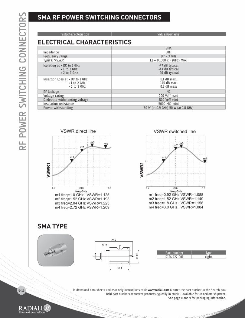
SMA TYPE
ELECTRICAL CHARACTERISTICS SMA
Impedance 50ΩFrequency range DC - 3 GHzTypical V.S.W.R. 1.1 + 0.1000 x F (GHz) Maxi
Isolation at • DC to 1 GHz • 1 to 2 GHz • 2 to 3 GHz
-47 dB typical -43 dB typical -40 dB typical
Insertion Loss at • DC to 1 GHz • 1 to 2 GHz • 2 to 3 GHz
0.1 dB maxi 0.15 dB maxi 0.2 dB maxi
RF leakage NAVoltage rating 300 Veff maxiDielectric withstanting voltage 500 Veff miniInsulation resistance 5000 MΩ miniPower withstanding 80 W (at 0.9 GHz) 50 W (at 1.8 GHz)
Test/characteristics Values/remarks
SMA RF POWER SWITCHINg CONNECTORS
Part number TypeR124 422 001 right
To download data sheets and assembly instructions, visit www.radiall.com & enter the part number in the Search box.Bold part numbers represent products typically in stock & available for immediate shipment.
See page 8 and 9 for packaging information.

6-17
RF P
OWER
SW
ITCH
ING
CONNEC
TORSQN RF POWER SWITCHINg CONNECTORS
To download data sheets and assembly instructions, visit www.radiall.com & enter the part number in the Search box.Bold part numbers represent products typically in stock & available for immediate shipment.See page 8 and 9 for packaging information.
ELECTRICAL CHARACTERISTICS QN
Impedance 50ΩFrequency range DC - 3 GHzTypical V.S.W.R. 1.1 + 0.09 x F (GHz) Maxi
Isolation at • DC to 1 GHz • 1 to 2 GHz • 2 to 3 GHz
-47 dB typical -43 dB typical -40 dB typical
Insertion Loss at • DC to 1 GHz • 1 to 2 GHz • 2 to 3 GHz
0.1 dB maxi 0.15 dB maxi 0.2 dB maxi
RF leakage NAVoltage rating 300 Veff maxiDielectric withstanting voltage 500 Veff miniInsulation resistance 5000 MΩ miniPower withstanding 110 W (at 2 GHz)
QN TYPE
Test/characteristics Values/remarks
Part number TypeR164 428 823 leftR164 428 833 right
m1 freq=1. 0 GHz VSWR = 1.084 m2 freq= 2.0 GH z VSWR= 1.097 m3 freq= 3.0 GH z V SWR= 1.212 m4 freq= 0.52 GHz VSWR= 1.054
m1 freq=1. 0 GHz VSWR = 1.027m2 freq= 2.0 GHz VSWR = 1.043
m3 freq= 3.0 GHz VSWR = 1.137m4 freq= 1.6 GHz VSWR = 1.020
6-18
RF P
OWER
SW
ITCH
ING
CONNEC
TORS
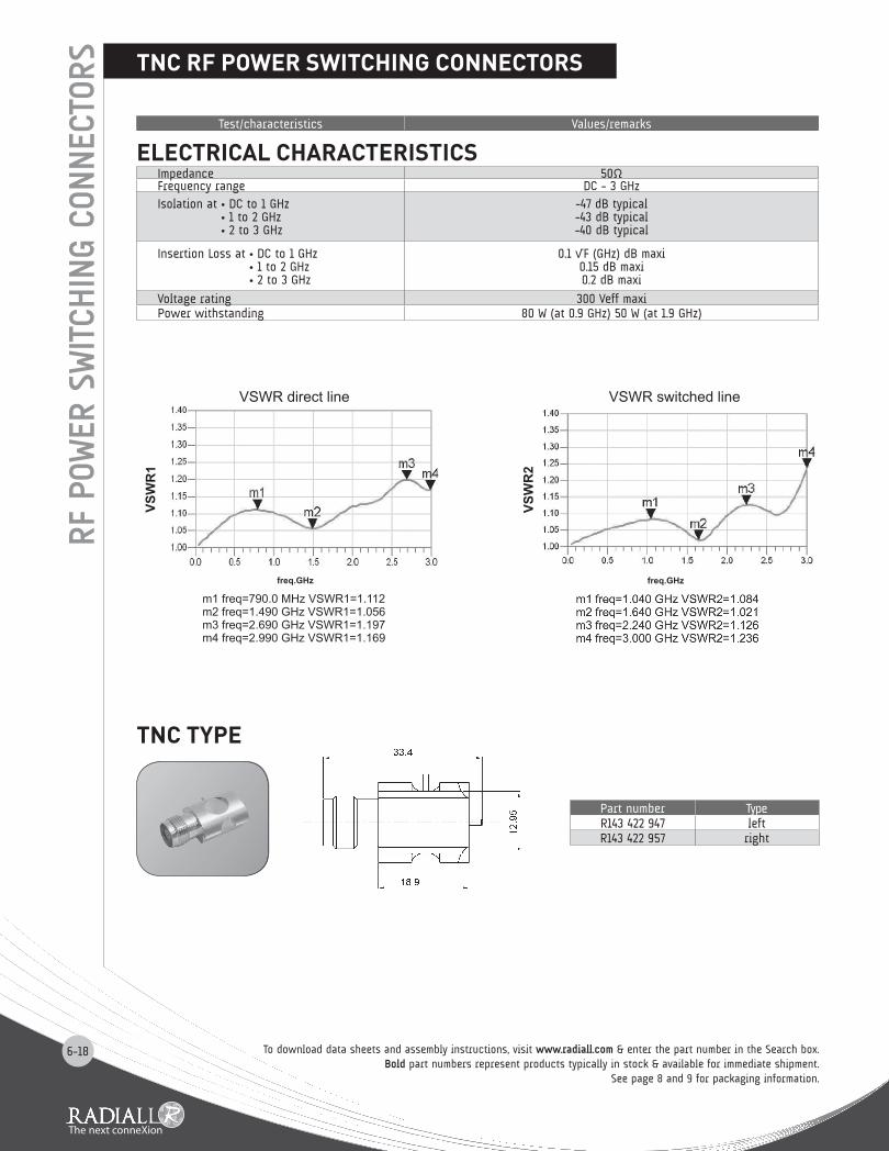
ELECTRICAL CHARACTERISTICS Impedance 50ΩFrequency range DC - 3 GHzIsolation at • DC to 1 GHz
• 1 to 2 GHz • 2 to 3 GHz
-47 dB typical -43 dB typical -40 dB typical
Insertion Loss at • DC to 1 GHz • 1 to 2 GHz • 2 to 3 GHz
0.1 √F (GHz) dB maxi 0.15 dB maxi 0.2 dB maxi
Voltage rating 300 Veff maxiPower withstanding 80 W (at 0.9 GHz) 50 W (at 1.9 GHz)
Test/characteristics Values/remarks
TNC TYPE
TNC RF POWER SWITCHINg CONNECTORS
To download data sheets and assembly instructions, visit www.radiall.com & enter the part number in the Search box.Bold part numbers represent products typically in stock & available for immediate shipment.
See page 8 and 9 for packaging information.
Part number TypeR143 422 947 leftR143 422 957 right

COAXIAL, RF & MICROWAVE
2011 COMPANY PROFILESimply Your Best ConnectionRadiall is a global leader in the design, development and
manufacturing of leading edge interconnect solutions. Dedicated
to understanding its customers’ needs since 1952, Radiall has
earned the reputation of being “the best of the best” in engineering
ingenuity by providing a constant flow of creative system solutions
serving the telecommunications, aerospace, defense, instrumentation,
automotive, industrial, medical and broadcast markets.
The Best End-to-End Interconnect SolutionsWe offer an extensive range of solutions that supports the most demanding signal transmission applications.
4G wireless infrastructure, active array radars, IED’s detection, electrical wiring in aircrafts, soldier tactical radios,
in-vehicle communications networks, and magnetic resonance imaging systems are just a few of the complex
applications that we support.
Best Value-added Services• Collaboration: We work closely with your engineers to understand your business, your technical needs, and your
budgetary issues;
• Wide Product Range: We manage our product lines thru the entire lifecycle in order to offer you a wide selection of
standard products at an affordable cost;
• Custom Products: We can tailor products to specific equipment and application needs;
• Global Presence: We’re everywhere you need us, with worldwide sales, engineering support, R&D in North America,
Europe, and Asia, and manufacturing facilities strategically located in the United States, Mexico, France, India, and China;
• Responsive Support and Service: From the design stage, planning to post-installation support, we’re with you at every
step, whether you need sales support or engineering expertise;
• On-time Delivery: We support your logistical needs so you get the products when and where you need them;
• Warranty: We proudly stand behind our products.
Certifications and EnvironmentalRadiall is ISO 9001: 2008 certified and dedicated to continuous improvement
programs that have resulted in also being AS9100, TS16949 and ISO 14001
certified. In addition, Radiall is committed to investing in its people, future
technologies and the environment, such as being RoHS (Restriction of Hazardous Substances) and REACH (Registration,
Evaluation, Authorization and Restriction of Chemical substances) compliant.
• RF coaxial connectors• Fiber optic connectors and transceivers• Coaxial and fiber optic cable assemblies and harnesses• High frequency microwave components• Coaxial switches, including the smallest and most reliable SPDT relay
• Multipin rectangular connectors• Rack and panel connectors• Antennas for tactical networks, aerospace and instrumentation
Technical information and sales contacts are available at : www.radiall.com
www.radiall.com
COAXIAL, RF & MICROWAVEFull Line Catalog
www.radiall.com
Cable designation
Cable Group / Ω
Imp.Ω
Cable dimensions mm (inch) Radiall cable if applicable
Core type Core Insulator Screen Outer P/N RemarkRG 174 A/U 2.6 / 50 S 50 7 x 0.16 0.48 (.019) 1.52 (.060) S 2.79 (.110) C291 150 000 PVC jacketRG 178 B/U 2 / 50 S 50 7 x 0.1 0.30 (.012) 0.84 (.033) S 1.78 (.070) C291 145 007 FEP jacketRG 178 B/U 2 / 50 S 50 7 x 0.1 0.30 (.012) 0.84 (.033) S 1.83 (.072) C291 145 060 PVC jacketRG 178 non m. 2 / 50 S 50 7 x 0.1 0.29 (.011) 0.84 (.033) S 1.80 (.071) C291 140 087 non magnetic / FEP jacketRG 179 B/U 2.6 / 75 S 75 7 x 0.1 0.30 (.012) 1.60 (.063) S 2.54 (.010) C291 210 007 FEP jacketRG 187 A/U 2.6 / 75 S 75 7 x 0.1 0.30 (.012) 1.60 (.063) S 2.79 (.110) C291 211 006 PTFE jacketRG 188 A/U 2.6 / 50 S 50 7 x 0.17 0.51 (.020) 1.52 (.060) S 2.79 (.110) C291 160 006 PTFE jacketRG 196 A/U 2 / 50 S 50 7 x 0.1 0.30 (.012) 0.86 (.034) S 2.03 (.080) C291 110 006 PTFE jacketRG 212 /U 8 / 50 D 50 solid 1.41 (.056) 4.70 (.185) D 8.43 (.331) naRG 213 /U 10 / 50 S 50 7 x 0.75 2.26 (.089) 7.24 (.285) S 10.30 (.406) C291 510 000 PVC jacketRG 214 /U 11 / 50 D 50 7 x 0.75 2.25 (.089) 7.24 (.285) D 10.80 (.425) C291 600 000 PVC jacket
RG 215 10 / 50 S 50 7 x 0.75 2.25 (.089) 7.25 (.285) S 10.29 (.405) naRG 216 /U 11 / 75 D 75 7 x 0.4 1.21 (.048) 7.24 (.285) D 10.80 (.425) C291 610 000 PVC jacketRG 217 /U 14 / 50 D 50 solid 2.69 (.106) 9.40 (.370) D 13.84 (.545) C291 620 000 PVC jacketRG 218 /U 22 / 50 S 50 solid 4.95 (.195) 17.27 (.680) S 22.10 (.870) C291 630 000 PVC jacketRG 223 /U 5 / 50 D 50 solid 0.89 (.035) 2.95 (.116) D 5.38 (.212) C291 330 000 PVC jacketRG 225 /U 11 / 50 D 50 7 x 0.8 2.38 (.094) 7.24 (.285) D 10.90 (.429) C291 605 007 glass fiber jacketRG 303 /U 5 / 50 S 50 solid 0.94 (.037) 2.95 (.116) S 4.32 (.170) naRG 316 /U 2.6 / 50 S 50 7 x 0.17 0.53 (.021) 1.52 (.060) S 2.49 (.098) C291 170 007 FEP jacket
RD 316 2.6 / 50 D 50 7 x 0.17 0.53 (.021) 1.52 (.060) D 2.80 (.110) C291 185 067 FEP jacketRG 393 10 / 50 D 50 7 x 0.81 2.39 (.094) 7.24 (.285) D 9.91 (.390) C291 511 007 FEP jacketRG 400 5 / 50 / D 50 19 x 0.19 0.98 (.039) 2.95 (.116) D 4.95 (.195) C291 324 007 FEP jacket
Flexible cable BT approvedRD 179 2.6 / 75 D 75 7 x 0.10 0.30 (.012) 1.6 (.063) D 3.07 (.121) C291 230 080 LSOH jacketBT 3002 3.6 / 75 D 75 solid 0.31 (.012) 1.95 (.077) D 3.55 (.140) C291 246 046 FEP jacketBT 2002 5 / 75 D 75 7 x 0.20 0.60 (.024) 2.5 (.098) D 5.1 (.200) C291 333 080 FEP jacket
Semi rigid cables MIL-C-17 standardRG 401 /U .250" 50 solid 1.63 (.064) 5.31 (.209) -- 6.35 (.250) C291 870 001 copper tubingRG 401 alu .250" 50 solid 1.63 (.064) 5.31 (.209) -- 6.35 (.250) C291 874 187 tinned alu tubingRG 402 /U .141" 50 solid 0.92 (.036) 2.98 (.117) -- 3.58 (.141) C291 860 001 copper tubingRG 402 tin .141" 50 solid 0.92 (.036) 2.98 (.117) -- 3.58 (.141) C291 862 005 tinned copper tubingRG 402 silver .141" 50 solid 0.92 (.036) 2.98 (.117) -- 3.58 (.141) C291 861 066 silvered copper tubingRG 402 alu .141" 50 solid 0.92 (.036) 2.98 (.117) -- 3.58 (.141) C291 864 187 tinned alu tubing
RG 402 non m. .141" 50 solid 0.92 (.036) 2.98 (.117) -- 3.58 (.141) C291 861 061 non magnetic / copper tubingRG 405 /U .085" 50 solid 0.51 (.020) 1.68 (.066) -- 2.20 (.087) C291 850 001 copper tubingRG 405 tin .085" 50 solid 0.51 (.020) 1.68 (.066) -- 2.20 (.087) C291 850 005 tinned copper tubingRG 405 alu .085" 50 solid 0.51 (.020) 1.68 (.066) -- 2.20 (.087) C291 844 187 tinned alu tubing
RG 405 non m. .085" 50 solid 0.51 (.020) 1.68 (.066) -- 2.20 (.087) C291 851 001 non magnetic / copper tubing.047" .047" 50 solid 0.29 (.011) 0.94 (.037) -- 1.19 (.047) C291 855 001 copper tubing
.047" tin .047" 50 solid 0.29 (.011) 0.94 (.037) -- 1.19 (.047) C291 855 065 tinned copper tubingHand-formable cable
Hand-formable .085" 50 solid 0.51 (.020) 1.63 (.064) -- 2.21 (.087) C291 844 065 tin soaked braidHand-formable .141" 50 solid 0.92 (.036) 2.95 (.116) -- 3.50 (.138) C291 864 065 tin soaked braidHand-formable .141" 50 solid 0.92 (.036) 2.98 (.117) -- 4.05 (.159) C291 866 378 FEP jacketHand-formable .141" 50 solid 0.92 (.036) 2.98 (.117) -- 4.50 (.177) C291 866 270 LSZH jacket
Corrugated cables (with helical or ringed/annular copper tube)Flexible 1/4" 50 solid 2.38 (.094) 6.40 (.252) -- 8.70 (.343) na ringed/annular tubeFlexible 1/2" 50 solid 4.80 (.189) 11.6 (.457) -- 16.35 (.644) C291 972 085 ringed/annular tubeFlexible 7/8" 50 solid 9.13 (.359) 22.5 (.866) -- 27.7 (1.091) na ringed/annular tubeFlexible 1 1/4" 50 solid 12.7 (.500) 32.5 (1.28) -- 39.5 (1.55) na ringed/annular tubeFlexible 1 5/8" 50 solid 17.3 (.681) 43.5 (1.71) -- 50.5 (1.99) na ringed/annular tube
Super flexible 1/4" 50 solid 1.90 (.075) 4.70 (.185) -- 7.40 (.291) C291 993 080 helical tubeSuper flexible 3/8" 50 solid 2.60 (.102) 6.30 (.248) -- 10.8 (.425) C291 996 070 helical tubeSuper flexible 1/2" 50 solid 3.60 (.142) 8.70 (.343) -- 13.2 (.520) C291 994 080 helical tubeSuper flexible 7/8" 50 tube 9.04 (.356) 23.62 (.930) -- 27.48 (1.082) C291 996 580 helical tube
Note: S = single braid. D = dual braid. For more information about cables manufactured by Radiall, please consult our online catalog.
www.radiall.com
D1C
004X
E -
2010
Nov
embe
r Ed
ition
AEROspace AUTOMOTIVE DEFENSE INDUSTRIAL INSTRUMENTATION SPACE TELECOMMEDICAL
India - RADIALL India Pvt. Ltd
S.A.
.
.
.
.
Poi
ntVi
rgul
e +3
3 3
44 2
3 48
48