swz operators manual 03226 rev 2 w-spanish scag approved attachments and accessories 32 caster...
TRANSCRIPT

PART NO. 03226 Rev. 2PRINTED 1/2009PRINTED IN USA
© 2009Scag Power EquipmentDivision of Metalcraft of Mayville, Inc.
Congratulations on owning a Scag mower! This manual contains the operating instructions and safety information for your Scag mower. Reading this manual can provide you with assistance in maintenance and adjustment procedures to keep your mower performing to maximum efficiency. The specific models that this book covers are listed on the inside cover. Before operating your machine, please read all the information enclosed.
SWZWalk-BehindModel: SWZ36A-16KAI SWZ36A-17KAI SWZ48V-17KAI SWZ52V-17KAI SWZ52V-19KAI SWZ-19KAI SWZ-21KAE
OPERATOR’S MANUAL

WARNING
FAILURE TO FOLLOW SAFE OPERATING PRACTICES MAY RESULT IN SERIOUS INJURY OR DEATH.
Read this manual completely as well as other manuals that came with your mower.•
ALWAYS FOLLOW OSHA APPROVED OPERATION.•
DO NOT operate on steep slopes. •
Always travel across slopes.•
DO NOT mow on wet grass. Wet grass reduces traction and steering control.•
Keep all shields in place, especially the grass discharge chute.•
Before performing any maintenance or service, stop the machine and remove the •spark plug wire and ignition key.
If a mechanism becomes clogged, stop the engine before cleaning.•
Keep hands, feet and clothing away from power-driven parts.•
Keep others off the mow• er (only one person at a time)
REMEMBER - YOUR MOWER IS ONLY AS SAFE AS THE OPERATOR!
HAzARD CONTROL AND ACCIDENT PREvENTION ARE DEPENDENT UPON THE AWARENESS, CONCERN, PRUDENCE, AND PROPER TRAINING OF THE PERSONNEL INvOLvED IN THE OPERATION, TRANSPORT, MAINTENANCE, AND STORAGE OF THE EqUIPMENT.
This manual covers the operating instructions and illustrated parts list for:
SWz36A-16KAI with a serial number of D4500001 to D4599999
SWz36A-17KAI with a serial number of E6100001 to E6199999
SWz48v-17KAI with a serial number of D4600001 to D4699999
SWz52v-17KAI with a serial number of D4700001 to D4799999
SWz52v-19KAI with a serial number of D4800001 to D4899999
SWz-19KAI with a serial number of D5100001 to D5199999
SWz-21KAE with a serial number of D5200001 to D5299999
SWM-52v with a serial number of D5400001 to D5499999
SWM-61v with a serial number of D5500001 to D5599999
Always use the entire serial number listed on the serial number tag when referring to this product.

I
RTable of Contents
Table of ContentsGENERAL INFORMATIONSECTION 1 - ...................................................................................1
1.1 INTRODUCTION ...........................................................................................................................................1
1.2 DIRECTION REFERENCE ...........................................................................................................................1
1.3 SERvICING THE ENGINE AND DRIvE TRAIN COMPONENTS .................................................................1
1.4 SYMBOLS ....................................................................................................................................................2
SAFETY INFORMATIONSECTION 2 - ......................................................................................32.1 INTRODUCTION ...........................................................................................................................................3
2.2 SIGNAL WORDS ..........................................................................................................................................3
2.3 BEFORE OPERATION CONSIDERATIONS ................................................................................................3
2.4 OPERATION CONSIDERATIONS ................................................................................................................4
2.5 MAINTENANCE CONSIDERATIONS & STORAGE ....................................................................................5
2.6 USING A SPARK ARRESTOR .....................................................................................................................6
2.7 SAFETY AND INSTRUCTIONAL DECALS .................................................................................................7
SPECIFICATIONSSECTION 3 - ................................................................................................83.1 ENGINE ........................................................................................................................................................8
3.2 ELECTRICAL ...............................................................................................................................................8
3.3 ENGINE DECK .............................................................................................................................................8
3.4 CUTTER DECK ............................................................................................................................................9
3.5 WEIGHTS AND DIMENSIONS .....................................................................................................................9
3.6 PRODUCTIvITY ...........................................................................................................................................9
OPERATING INSTRUCTIONSSECTION 4 - ...........................................................................104.1 CONTROLS AND INSTRUMENT IDENTIFICATION ................................................................................10
4.2 SAFETY INTERLOCK SYSTEM ................................................................................................................11
4.3 INITIAL RUN-IN PROCEDURES ................................................................................................................11
4.4 STARTING THE ENGINE ...........................................................................................................................11
4.5 GROUND TRAvEL AND STEERING .........................................................................................................11
4.6 ENGAGING THE DECK DRIvE (CUTTER BLADES) ................................................................................12
4.7 HILLSIDE OPERATION ..............................................................................................................................13
4.8 PARKING THE MOWER .............................................................................................................................13
4.9 AFTER OPERATION ..................................................................................................................................13
4.10 REMOvING CLOGGED MATERIAL ........................................................................................................13
4.11 MOvING MOWER WITH ENGINE STOPPED ..........................................................................................14
4.12 RECOMMENDATIONS FOR MOWING ....................................................................................................14
TROUBLESHOOTING CUTTING CONDITIONSSECTION 5 - ...............................................15

II
R Table of Contents
ADJUSTMENTSSECTION 6 - .................................................................................................186.1 PARKING BRAKE ADJUSTMENT ............................................................................................................18
6.2 NEUTRAL ADJUSTMENT .........................................................................................................................18
6.3 STEERING CONTROL ROD ADJUSTMENTS ..........................................................................................18
6.4 TRACKING ADJUSTMENT ........................................................................................................................19
6.5 THROTTLE CONTROL AND CHOKE ADJUSTMENTS ............................................................................19
6.6 CUTTER DECK BELT ADJUSTMENTS ....................................................................................................19
6.7 BELT ALIGNMENT .....................................................................................................................................20
6.8 ADJUSTING CUTTING HEIGHT ................................................................................................................20
6.9 ELECTRIC CLUTCH ADJUSTMENT .........................................................................................................23
MAINTENANCESECTION 7 - ..................................................................................................247.1 MAINTENANCE CHART - RECOMMENDED SERvICE INTERvALS ......................................................24
7.2 LUBRICATION ............................................................................................................................................25
7.3 HYDRAULIC SYSTEM ...............................................................................................................................27
7.4 ENGINE OIL ...............................................................................................................................................28
7.5 ENGINE FUEL SYSTEM ............................................................................................................................28
7.6 ENGINE AIR CLEANER .............................................................................................................................29
7.7 BATTERY - ELECTRIC START MODELS..................................................................................................29
7.8 CUTTER BLADES ......................................................................................................................................30
7.9 TIRES ..........................................................................................................................................................31
ILLUSTRATED PARTS LISTSECTION 8 - ..............................................................................328.1 SCAG APPROvED ATTACHMENTS AND ACCESSORIES. .....................................................................32
CASTER ASSEMBLY .......................................................................................................................................33
36A CUTTER DECK .........................................................................................................................................34
48v & 52v CUTTER DECKS ...........................................................................................................................36
61v CUTTER DECK .........................................................................................................................................38
ENGINE DECK - MANUAL START ..................................................................................................................40
ENGINE DECK - ELECTRIC START ...............................................................................................................42
DRIvE AND BRAKE COMPONENTS ..............................................................................................................44
HANDLE ASSEMBLY - 16" SMALL FRAME ..................................................................................................46
HANDLE ASSEMBLY - 20" LARGE FRAME ..................................................................................................48
HYDRAULIC ASSEMBLY.................................................................................................................................50
HYDRAULIC PUMP ASSEMBLY .....................................................................................................................52
WIRE HARNESSES .........................................................................................................................................54
WIRE HARNESSES .........................................................................................................................................55
WIRE HARNESSES .........................................................................................................................................56
REPLACEMENT DECALS AND INFORMATION PLATES .............................................................................57
LIMITED WARRANTY - COMMERCIAL EqUIPMENT .........................Following Section 8

1
RSection 1
INTRODUCTION1.1
Your mower was built to the highest standards in the industry. However, the prolonged life and maximum efficiency of your mower depends on you following the operating, maintenance and adjustment instructions in this manual.
If additional information or service is needed, contact your Scag Power Equipment Dealer.
We encourage you to contact your dealer for repairs. All Scag dealers are informed of the latest methods to service this equipment and provide prompt and efficient service in the field or at their service shop. They carry a full line of Scag service parts.
- IMPORTANT -
The replacement of any part on this product by other than the manufacturer's authorized replacement part may adversely affect the performance, durability or safety of this product.
Use of other than original Scag replacement parts will void the warranty.
When ordering parts, always give the model and serial number of your mower. The serial number plate is located on the frame of the machine between the engine and transmission were shown in Figure 1-1.
R
MODEL
SERIAL
Division of M
etalcraft o
f Mayv
ille, In
c.
Mayville
, Wisc
onsin 5
3050
Patents Iss
ued and Pending
SERIAL NUMBERPLATE LOCATION
Mower Serial Number Plate LocationFigure 1-1.
GENERAL INFORMATIONUSE ONLY SCAG APPROvED ATTACHMENTS AND ACCESSORIES.
Attachments and accessories manufactured by companies other than Scag Power Equipment are not approved for use on this machine. See Section 8-1.
WARNINGFor pictorial clarity, some illustrations and figures in this manual may show shields, guards or plates open or removed. Under no circumstances should your mower be operated without these devices in place.
All information is based upon product information available at the time of approval for printing. Scag Power Equipment reserves the right to make changes at any time without notice and without incurring any obligation.
DIRECTION REFERENCE1.2
The “Right” and “Left”, “Front” and “Rear” of the machine are referenced from the operator’s right and left when in the normal operating position and facing the forward travel direction.
SERvICING THE ENGINE AND DRIvE 1.3 TRAIN COMPONENTS
The detail servicing and repair of the engine and transmission are not covered in this manual; only routine maintenance and general service instructions are provided. For service of these components during the limited warranty period, it is important to contact your Scag dealer or find a local authorized servicing agent of the component manufacturer. Any unauthorized work done on these components during the warranty period may void your warranty.

2
R Section 1
SYMBOLS1.4
SYMBOL DESCRIPTION SYMBOL DESCRIPTION
Choke
Transmission
Parking Brake
48071S
Spinning Blade
On/Start
Spring Tension on Idler
Off/Stop
Oil
Falling Hazard
Thrown Object Hazard
Fast
Slow
Continuously Variable - Linear
Cutting Element - Basic Symbol
481039S
Pinch Point
Cutting Element - Engage
Hour meter/Elapsed Operating Hours
Cutting Element - Disengage
STT MODELS
Seat must be installed under the seat hold down bracket during installation. Failure to secure the seat under the hold down bracket could result in serious injury or death in a roll over.
CE Mark
Thrown Object HazardKeep Bystanders Away
Read Operator's Manual

3
RSection 2
INTRODUCTION2.1
Your mower is only as safe as the operator. Carelessness or operator error may result in serious bodily injury or death. Hazard control and accident prevention are dependent upon the awareness, concern, prudence, and proper training of the personnel involved in the operation, transport, maintenance and storage of the equipment. Make sure every operator is properly trained and thoroughly familiar with all of the controls before operating the mower. The owner/user can prevent and is responsible for accidents or injuries occurring to themselves, other people or property.
READ THIS OPERATOR’S MANUAL BEFORE ATTEMPTING TO START YOUR MOWER.
A replacement manual is available from your authorized Scag Service Dealer or by contacting Scag Power Equipment, Service Department at P.O. Box 152, Mayville, WI 53050 or contact us via the Internet at www.scag.com. The manual for this machine can be downloaded by using the model and serial number or use the contact form to make your request. Please indicate the complete model and serial number of your Scag product when requesting replacement manuals.
SIGNAL WORDS2.2
This symbol means “Attention! Become Alert! Your Safety is Involved!" The symbol is used with the following signal words to attract your attention to safety messages found on the decals on the machine and throughout this manual. The message that follows the symbol contains important information about safety. To avoid injury and possible death, carefully read the message! Be sure to fully understand the causes of possible injury or death.
SIGNAL WORD:
It is a distinctive word found on the safety decals on the machine and throughout this manual that alerts the viewer to the existence and relative degree of the hazard.
DANGER
The signal word “DANGER” denotes that an extremely hazardous situation exists on or near the machine that could result in high probability of death or irreparable injury if proper precautions are not taken.
WARNING
The signal word “WARNING” denotes that a hazard exists on or near the machine that can result in injury or death if proper precautions are not taken.
CAUTION
The signal word “CAUTION” is a reminder of safety practices on or near the machine that could result in personal injury if proper precautions are not taken.
Your safety and the safety of others depends significantly upon your knowledge and understanding of all correct operating practices and procedures of this machine.
BEFORE OPERATION 2.3 CONSIDERATIONS
NEVER allow children to operate this mower. Do not 1. allow adults to operate this machine without proper instructions.
Do not mow when children and/or others are 2. present. Keep children out of the mowing area and in the watchful care of a responsible adult other than the operator. Be alert and turn machine off if a child enters the area.
DO NOT allow children to ride or play on the 3. machine, it is not a toy.
Clear the area to be mowed of objects that could be 4. picked up and thrown by the cutter blades.
DO NOT carry passengers.5.
DO NOT operate the machine under the influence of 6. alcohol or drugs.
SAFETY INFORMATION

4
R Section 2
If the operator(s) or mechanic(s) cannot read English 7. or Spanish, it is the owner's responsibility to explain this material to them.
DO NOT wear loose fitting clothing. Loose clothing, 8. jewelry or long hair could get tangled in moving parts. Do not operate the machine wearing shorts; always wear adequate protective clothing including long pants. Wearing safety glasses, safety shoes and a helmet is advisable and is required by some local ordinances and insurance regulations.
WARNINGAlways wear hearing protection. Operating this machine over prolonged periods of time can cause loss of hearing.
Keep the machine and attachments in good 9. operating condition. Keep all shields and safety devices in place. If a shield, safety device or decal is defective or damaged, repair or replace it before operating the machine.
WARNINGThis machine is equipped with an interlock system intended to protect the operator and others from injury. This is accomplished by preventing the engine from starting unless the deck drive is disengaged and the transmission is in neutral. The system shuts off the engine if the operator releases the operator pressence levers with the deck drive engaged and/or the transmission is not in neutral. Never operate equipment with the interlock system disconnected or malfunctioning.
Be sure the interlock switches are functioning 10. correctly.
Fuel is flammable; handle it with care. Fill the fuel 11. tank outdoors. Never fill it indoors. Use a funnel or spout to prevent spillage. Clean up any spillage before starting the engine.
DO NOT add fuel to a running or hot engine. Allow 12. the engine to cool for several minutes before adding fuel. Never fuel indoors or inside enclosed trailers.
Keep flammable objects (cigarettes, matches, etc.), 13. open flames and sparks away from the fuel tank and fuel container. Use only approved containers.
Equipment must comply with the latest requirements 14. per SAE J137 and/or ANSI/ASAE S279 when driven on public roads.
Do not operate without the side discharge chute 15. installed and in the down position or with an optional grass catcher or mulch plate completely installed.
Check the blade mounting bolts at frequent intervals 16. for proper tightness.
OPERATION CONSIDERATIONS2.4
Know the function of all controls and how to stop 1. quickly.
WARNINGDO NOT operate on steep slopes. ALWAYS FOLLOW OSHA APPROvED OPERATION.
Reduce speed and exercise extreme caution on 2. slopes and in sharp turns to prevent tipping or loss of control. Be especially cautious when changing directions on slopes.
To prevent tipping or loss of control, start and stop 3. smoothly, avoid unnecessary turns and travel at reduced speed.
When using any attachment, never direct the 4. discharge of material toward bystanders or allow anyone near the machine while in operation.
Start the engine when the neutral latches are in 5. the neutral lock position, the cutter blades are disengaged, parking brake is engaged and the speed control lever is in neutral.
If the mower discharge ever plugs, shut off the 6. engine, remove the ignition key, and wait for all movement to stop before removing the obstruction.

5
RSection 2
WARNINGDO NOT use your hand to dislodge the clogged discharge chute. Use a stick or other device to remove clogged material after the engine has stopped running and the blades have stopped turning.
Be alert for holes, rocks, roots and other hidden 7. hazards in the terrain. Keep away from any drop-offs. Beware of overhead obstructions (low limbs, etc.), underground obstacles (sprinklers, pipes, tree roots, etc.). Cautiously enter a new area. Be alert for hidden hazards.
Disengage power to cutter deck before backing up. 8. Do not mow in reverse unless absolutely necessary and then only after observation of the entire area behind the mower. If you must mow in reverse, maintain a constant lookout to the rear of the machine and mow slowly.
DO NOT turn sharply. Use care when backing up.9.
Disengage power to cutter deck before crossing 10. roads, walks or gravel drives.
Mow only in daylight or good artificial light.11.
NEVER raise the deck with the blades engaged.12.
Take all possible precautions when leaving the 13. machine unattended, such as disengaging the mower, stopping the engine, and removing the key.
Disengage power to the attachments when 14. transporting or when not in use.
The machine and attachments should be stopped 15. and inspected for damage after striking a foreign object, and damage should be repaired before restarting and operating the machine.
CAUTIONDo not touch the engine or the muffler while the engine is running or immediately after stopping. These areas may be hot enough to cause a burn.
DANGERDO NOT run the engine inside a building or a confined area without proper ventilation. Exhaust fumes are hazardous and contain carbon monoxide which can cause brain injury and death.
Keep hands and feet away from cutter blades and 16. moving parts. Contact can injure.
Transport the mower using a heavy duty trailer 17. or truck. Insure the trailer or truck has all of the necessary lighting and markings as required by laws, codes, and ordinances. Secure a trailer with a safety chain.
Be cautious when loading and unloading onto 18. trailers or trucks. Use only a full width ramp.
When transporting the mower, make sure the speed 19. control lever is in neutral, the neutral latches are in the neutral lock position, the engine is off with the key removed, the parking brake is engaged and the wheels have been blocked.
Tie the mower down securely using straps, chains, 20. cable, or ropes. Both front and rear straps must be directed down and outward from machine.
Use care when approaching blind corners, shrubs, 21. trees, or other objects that may obscure vision.
NEVER leave the machine running unattended.22.
MAINTENANCE CONSIDERATIONS & 2.5 STORAGE
Never make adjustments to the machine with the 1. engine running unless specifically instructed to do so. If the engine is running, keep hands, feet, and clothing away from moving parts.
Place the speed control lever in neutral, engage the 2. parking brake, neutral latches in the neutral lock position, stop engine and remove key or disconnect spark plug wire to prevent accidental starting of the engine when servicing or adjusting the machine. Wait for all movement to stop before adjusting, cleaning or repairing.

6
R Section 2
Remove spark plug wire before making any repairs. 3.
Keep all nuts, bolts and screws tight, to ensure the 4. machine is in safe working condition. Check blade mounting bolts frequently to be sure they are tight.
Do not change the engine governor settings or 5. overspeed the engine. See the engine operator's manual for information on engine settings.
To reduce fire hazard, keep the cutting units, drives, 6. muffler and engine free of grass, leaves, excessive grease, oil and dirt.
Park the machine on level ground.7.
NEVER allow untrained personnel to service the 8. machine.
Use care when checking blades. Use a Blade Buddy, 9. wrap the blade(s) or wear gloves and USE CAUTION when servicing blades. Only replace blades. NEVER straighten or weld blades.
Keep all parts in good working condition. Replace all 10. worn or damaged decals.
Use jack stands to support components when 11. required.
Carefully release pressure from components with 12. stored energy.
Let the engine cool before storing.13.
DO NOT store the machine near an open flame.14.
Shut off fuel while storing or transporting.15.
DO NOT store fuel near flames or drain indoors.16.
USING A SPARK ARRESTOR2.6
The engine in this machine is not equipped with a spark arrestor muffler. It is in violation of California Public Resource Code Section 4442 to use or operate this engine on or near any forest covered, brush covered or grass covered land unless the exhaust system is equipped with a spark arrestor meeting any applicable local or state laws. Other states or federal areas may have similar laws. Check with your state or local authorities for regulations pertaining to these requirements.

7
RSection 2
SAFETY AND INSTRUCTIONAL DECALS2.7
483402
483406
2009 SFW Safety Decals
Molded in Fuel Tank
!Avoid injury from burns.Shut off engine beforeremoving fuel tank cap.
WARNINGINSTALL BELT COvER BEFORE
OPERATING MACHINEREAD OPERATOR'S MANUAL
WARNINGFALLING HAzARD
USE ONLY SCAG APPROvEDRIDING ATTACHMENTS
SEE OPERATOR'S MANUAL 483404
MOUNT RIDINGATTACHMENT
HERE
WARNINGDO NOT OPERATE WITHOUT DISCHARGE CHUTE, MULCHING
KIT, OR ENTIRE GRASS CATCHER INSTALLED483405
WARNING
* Keep hands, feet & clothing clear* Keep all guards in place* Shut off engine & disengage blade clutch before servicing* Use caution in directing discharge* Read instruction manual before operating
ROTATING BLADES AND BELTS
DO NOT OPERATE UNLESS GRASS CATCHER, MULCHING KIT ORDISCHARGE CHUTE IS INSTALLED 483406
483404
SPINNING BLADESKEEP CLEAR
BLADE CONTACT & THROWNOBJECTS CAN INJURE
483505
483405
483505
WARNINGOperation of this equipmentmay create sparks that canstart �res around dry vegetation. A spark arrestor may be required.The operator should contact local �re agencies for laws or regulations relating to�re prevention requirements.
483900
483900(supplied with California models only)
CAUTION
BEFORE OPERATING
483907
*Read operator's manual
*Solicite etiquetas en espanol a un distribuidor Scag
*Make sure guards, shields & safety devices are in place & working
*Clear area of children, bystanders & debris
*Mow across face of slopes
*Trained operators only
WARNING
483907

8
R Section 3
SPECIFICATIONSENGINE3.1
General Type ................................................................................................Heavy Duty Industrial/Commercial GasolineBrand ..................................................................................................................................................................KawasakiHorsepower:
(Scag Model SWZ36A-16KAI) .................................................................................16 HP (Spec. # FH480V-BS24-R)(Scag Model SWZ36A-17KAI, SWZ48V-17KAI, SWZ52V-17KAI) ...........................17 HP (Spec.# FH541V-BS38-R)(Scag Model SWZ52V-19KAI, SWZ-19KAI) .............................................................19 HP (Spec.# FH580V-BS34-R)(Scag Model SWZ-21KAE) ......................................................................................21 HP (Spec. # FH641V-GS06-R)
Cylinders ...................................................................................................................2 with Cast-Iron Sleeves - KawasakiGovernor ................................................Mechanical Type with Variable Speed Control Set At 3600 RPM (+/- 100 RPM)Idle Speed:
Kawasaki ............................................................................................................................. 1550 RPM (+/- 150 RPM)Fuel ...................................................................................... Non-Leaded Gasoline with a Minimum Octane Rating of 87Oil Pump ...............................................................................................varies - see engine manufacturer's specificationsStarter:
Kawasaki ................................................................................................................................................ Recoil Starter
ELECTRICAL3.2
Starter ...................................................................................................................... Electrical Ignition with Recoil StarterInterlock Switches ................................................Operator Presence, Mower Engagement (BBC), Transmission NeutralInstrument Panel ................................................................................................Key Switch, Throttle Lever, PTO Switch,
ENGINE DECK3.3
Drive System .... Hydraulic Drive with Two Variable Displacement Pumps and Two Cast-Iron High Torque Wheel MotorsHydraulic Pumps ............................................................. Two Hydro-Gear model PG Series 10 cc. Hydraulic Pumps
with Dump Valves for movement without the engine runningHydraulic Drive Motors ...........................................Two Parker Model TE Series 12 cu. inch Cast-Iron Wheel Motors
Steering/Travel Control ..........................................Independent Handle Controls for each wheel, squeeze to move from forward to neutral to reverse, neutral lock lever, speed range controlled with single lever (patented design), in-field tracking adjustment with tool providedParking Brake ............................................................................................... 7.5" Drum, Band Brake, one on each wheelWheels:
(2) Front Caster ....................................................................................................9 X 3.5 Flat-Free w/Roller Bearings(2) Drive - .............................................................................. 16 x 6.5-8 Four-Ply Pneumatic Tubeless, Radius Edge
Tire Pressure:Front Caster....................................................................................................................................................Flat-FreeDrive .................................................................................................................................................................. 12 PSI
Fuel Tank ........................................................ 6-Gallon Seamless Polyethylene Tank with Large Opening and Fuel CapTravel Speed:
Forward .....................................................................................................................................................0 - 7.4 MPHReverse .....................................................................................................................................................0 - 3.0 MPH-NOTE- The machine will travel at 7.4 mph for transport purposes. For best cutting performance the forward travel speed should be adjusted depending upon the cutting conditions.

9
RSection 3
CUTTER DECK3.4
Type ......................................................................................................................Out-Front design with anti-scalp rollersConstruction ................ 36 / 48 = 7-Gauge Deck Top w/10-Gauge Reinforced Spindle Area, 7-gauge (3/16") Deck Skirt 52 / 61 = 10-Gauge Deck Top w/10-Gauge Reinforced Spindle Area, 7-Gauge (3/16") Deck SkirtTrue Cutting Width:
36 .........................................................................................................................................................35.5" (90.2 cm)48 ..........................................................................................................................................................48" (122.0 cm)52 ..........................................................................................................................................................52" (132.0 cm)61 ..........................................................................................................................................................61" (155.0 cm)
Cutting Height Adjustment ................................................................ Adjustment from, 1-3/4" to 4-1/4" in 1/4"incrementsCutter Blades ............................................................................. 0.197 in. Thick, Milled Edge, Wear Resistant Marbain™Blade Engagement ............................................................Electric Blade Engagement Clutch with Control Panel Switch Connected to the Cutter Deck through a Belt.Discharge Opening ...............................................Extra Wide Discharge Opening with Spring-Loaded Discharge ChuteDischarge Chute ...................................................................................................Black, Polypropylene (Plastic), FlexibleSpindles ............................................................................. Cast-Iron Housing, Tapered Roller Bearings with Top Access Grease Fitting and Grease Overfill Relief PoppetSpindle Pulleys ........................................................................................................Split Steel with Tapered Locking Hub Cutter Deck Belts ................................................................................................................... B-section with Kevlar CordsElectric Clutch Type ................................................................................................Ogura Heavy Duty PTO Clutch Brake
WEIGHTS AND DIMENSIONS 36A / 48v 52v 61v3.5
Length..................................................................................... 72" / 76" ............................ 76" ....................................78"Tracking Width ........................................................................ 37" / 37" ............................37"* ....................................41"Overall Width w/chute down ..................................................47" / 60.5" ..........................64.5" ................................73.5"Overall Width w/chute up ........................................................ 37" / 49" ............................ 53" ....................................62"Overall Height ...................................................................... 40.5" / 40.5" ........................40.5" ................................. 40.5Operating Weight ..................................................................515# / 565# ....................... 585#* ............................... 717#
PRODUCTIvITY 36 / 48 52 613.6
Cutting Width .......................................................................... 36" / 48" ............................ 52" ....................................61"Acres Per Day .........................................................................9.3 / 12.4 .......................... 13.5 .................................. 15.8The preceding chart will aid you in determining how many acres your Scag mower will cut per day. The chart is an estimate based on 8 hours per day cutting time at 4 MPH with a 20% allowance for overlap and turns.* Large Frame = Tracking Width - 41", Weight - 605#

10
R Section 4
CAUTIONDo not attempt to operate this mower unless you have read this manual. Learn the location and purpose of all controls and instruments before you operate this mower.
CONTROLS AND INSTRUMENT 4.1 IDENTIFICATION
Before operating the mower, familiarize yourself with all mower and engine controls. Knowing the location, function and operation of these controls is important for safe and efficient operation of the mower.
Ignition Switch (Figure 4-1).1. The ignition switch is used to start the engine. Turn the key to the on position before pulling the recoil starter.
OPERATING INSTRUCTIONSMower Deck Switch (Figure 4-1). 2. Used to engage and disengage the mower drive system. Pulling up on the switch will engage the deck drive. Pushing down on the switch will disengage the deck drive.
Engine Choke Control (Figure 4-1).3. Used to start a cold engine.
Engine Throttle Control (Figure 4-1).4. Used to control the engine speed. Pushing the lever forward increases engine speed. Pulling the lever back decreases engine speed. Full back position is the IDLE position. Full forward is the cutting position.
Left Steering Control (Figure 4-1). 5. Used to control the mower's left wheel when traveling forward or reverse. Pull upward for neutral and reverse.
Right Steering Control (Figure 4-1).6. Used to control the mower's right wheel when traveling forward or reverse. Pull upward for neutral and reverse.
LEFT STEERINGCONTROL
IGNITIONSWITCH
MOWERDECK
SWITCH
ENGINE THROTTLE CONTROL
RIGHT STEERINGCONTROL
NEUTRAL LATCH
NEUTRAL LATCH
OPERATOR PRESSENCECONTROL
OPERATOR PRESSENCECONTROL
BRAKE LEVERSPEED CONTROLLEVER
ENGINE CHOKECONTROL
Controls and InstrumentsFigure 4-1.

11
RSection 4
Speed Control Lever (Figure 4-1). 7. Used to select the forward speed.
Neutral Latch (Figure 4-1). 8. Used to secure the belt drive system in neutral. Apply neutral latches when parking the machine.
Operator Pressence Control (Figure 4-1)9. The operator pressence control levers must be depressed before the transmission is shifted out of neutral or engaging the mower deck.
Parking Brake Lever (Figure 4-1) 10. Used to engage and disengage the parking brake. Pull the lever back to engage the parking brake. Push the lever forward to disengage the parking brake.
SAFETY INTERLOCK SYSTEM4.2
The mower is equipped with a safety interlock system that shuts off the engine if the operator releases the operator presence levers with the deck drive engaged and/or the speed control lever not in neutral or the parking brake disengaged. Never operate equipment with the interlock system disconnected or malfunctioning..
WARNINGNever operate the mower with the interlock system disconnected or malfunctioning. Do not disengage or bypass any switch; injury to yourself and others or property damage could result.
INITIAL RUN-IN PROCEDURES4.3
FIRST DAY OF USE OR APPROxIMATELY 20 HOURS
Check all belts for proper alignment and wear at 2, 4 1. and 8 hours.
Change the engine oil and oil filter after the first 20 2. hours of operation. (See Section 7.4.)
Check for loose hardware. Tighten as needed.3.
Check interlock system for proper operation. (See 4. Section 4.2.)
Check tire pressure. Adjust pressure if necessary. 5. (See Section 7.10.)
STARTING THE ENGINE4.4
CAUTIONDO NOT USE STARTING FLUIDS. Use of starting fluids in the air intake system may be potentially explosive or cause a “runaway” engine condition that could result in engine damage and/or personal injury.
Be sure the fuel shutoff valve, located by the fuel 1. tank, is completely open. (See Section 7.5.)
Apply the neutral latch levers.2.
Shift the speed control lever into neutral.3.
Place the PTO switch in the disengaged position.4.
Apply the parking brake.5.
If the engine is cold, choke the engine as needed.6.
Move the engine throttle control to about half engine 7. speed.
Turn the ignition key to the ON position.8.
Pull the recoil starter on the engine.9.
Allow engine to warm before operating the mower.10.
GROUND TRAvEL AND STEERING4.5
- IMPORTANT -
If you are not familiar with the operation of a walk behind mower with a hydrostatic transmission, the steering and ground speed operations should be learned and practiced in an open area, away from buildings, fences, or obstructions.
Learn the operation on flat ground before operating on slopes.
Start practicing with a slow engine speed and slow forward travel.
Learn to feather the steering controls to obtain a smooth operating action.
Practice operating the mower until you are comfortable with the controls before proceeding to mow.

12
R Section 4
FORWARD TRAvEL
To travel forward with the mower, release the parking brake, select the desired speed using the speed control lever, pull steering control levers upward, release the neutral latch for both sides and slowly release both the left and right steering control levers. The higher the notch selected using the speed control lever, the faster the machine will travel.
To stop the forward travel, pull upward on the steering control levers, lock the neutral latches, shift the speed control lever into neutral and apply the parking brake.
To steer the mower left while traveling forward, pull upward on the left steering control lever. The further the lever is pulled upward, the quicker the mower will turn left.
To steer the mower right while traveling forward, pull upward on the right steering control lever. The further the lever is pulled upward, the quicker the mower will turn right.
- NOTE -
Smooth operation of the steering control levers will produce smooth mower operation. While learning the operation of the steering controls, keep the travel speed low.
REvERSE TRAvEL
CAUTIONDisengage power to the mower before backing up. Do not mow in reverse unless absolutely necessary and then only after observation of the entire area behind the mower.
CAUTIONBefore backing up, observe the rear for persons and obstructions. Clear the area before backing up. Possible injury or property damage could occur.
To travel in reverse, pull steering control levers upward. Keep the travel speed low while traveling in reverse.
- NOTE -
The mower may not travel straight in reverse.
To steer left while traveling in reverse, pull upward on the left steering control lever. The further the lever is pulled upward, the quicker the mower will turn left.
To steer right while traveling in reverse, pull upward on the right steering control lever. The further the lever is pulled upward, the quicker the mower will turn right.
ENGAGING THE DECK DRIvE (CUTTER 4.6 BLADES)
Set the throttle at about 3/4 speed. Do not attempt to 1. engage the deck drive at high speed as this shortens the electric clutch life — use only moderate engine speed when engaging the deck drive.
Engage the deck drive by pulling out on the yellow 2. switch, located on the instrument panel, to the engage position. See Figure 4-2.
390S0138
PULL UP TO ENGAGE
PUSH DOWN TO DISENGAGE
Cutter Engage SwitchFigure 4-2.
- NOTE -
A squealing noise may be heard when engaging or disengaging the deck drive. It is caused by the electric clutch plates meshing as the mower comes up to speed. This is normal.
To disengage the deck drive, push the switch in to 3. the disengage position.
Always operate the engine at full throttle to properly 4. maintain cutting speed. If the engine starts to lug down, reduce the forward speed and allow the engine to operate at maximum RPM.
13
RSection 4
HILLSIDE OPERATION4.7
WARNINGDO NOT operate on steep slopes. ALWAYS FOLLOW OSHA APPROvED OPERATION.
This mower has been designed for good traction and 1. stability under normal mowing conditions. However, caution must be used when traveling on slopes, especially when the grass is wet. Wet grass reduces traction and steering control.
To prevent tipping or loss of control, do not start or 2. stop suddenly, avoid unnecessary turns and travel at reduced speed. If tires lose traction, disengage blades and proceed slowly off the slope.
Avoid sudden starts when mowing on slopes.3.
Travel across the slope whenever possible. Never up 4. and down the slope.
Keep tires properly inflated.5.
PARKING THE MOWER4.8
Park the machine on a flat, level surface only. Do not 1. park the machine on an incline.
Disengage the cutter blades.2.
Shift the speed control lever into the neutral position, 3. lock the neutral latches and apply the parking brake.
Slow the engine to idle speed.4.
Turn the ignition key to the OFF position and remove 5. the key.
AFTER OPERATION4.9
Wash the entire mower after each use. Do not 1. use high pressure spray or direct the spray onto electrical components.
- IMPORTANT -
Do not wash a hot or running engine. Cold water will damage the engine. Use compressed air to clean the engine if it is hot.
Keep the entire mower clean to inhibit serious heat 2. damage to the engine or hydraulic oil circuit.
Check the drive belts for proper alignment and any 3. signs of wear. Correct and adjust if necessary.
DANGERTo avoid injury from burns, allow the mower to cool before removing the fuel tank cap and refueling.
After the mower has cooled down, fill the fuel tank 4. with fresh, clean fuel at the end of every day of operation. See Engine Owner's Manual for proper octane requirements.
Check the tire pressure. Adjust pressure if 5. necessary.
REMOvING CLOGGED MATERIAL4.10
DANGERROTATING BLADES
NEvER PUT YOUR HANDS INTO THE DISCHARGE CHUTE FOR ANY REASON!
Shut off the engine and remove the key and only then use a stick or similar object to remove material if clogging has occurred.
If the discharge chute becomes clogged, shut off 1. the engine and remove the ignition key. Using a stick or similar item, dislodge the clogged material. Then resume normal mowing.
14
R Section 4
MOvING MOWER WITH ENGINE 4.11 STOPPED
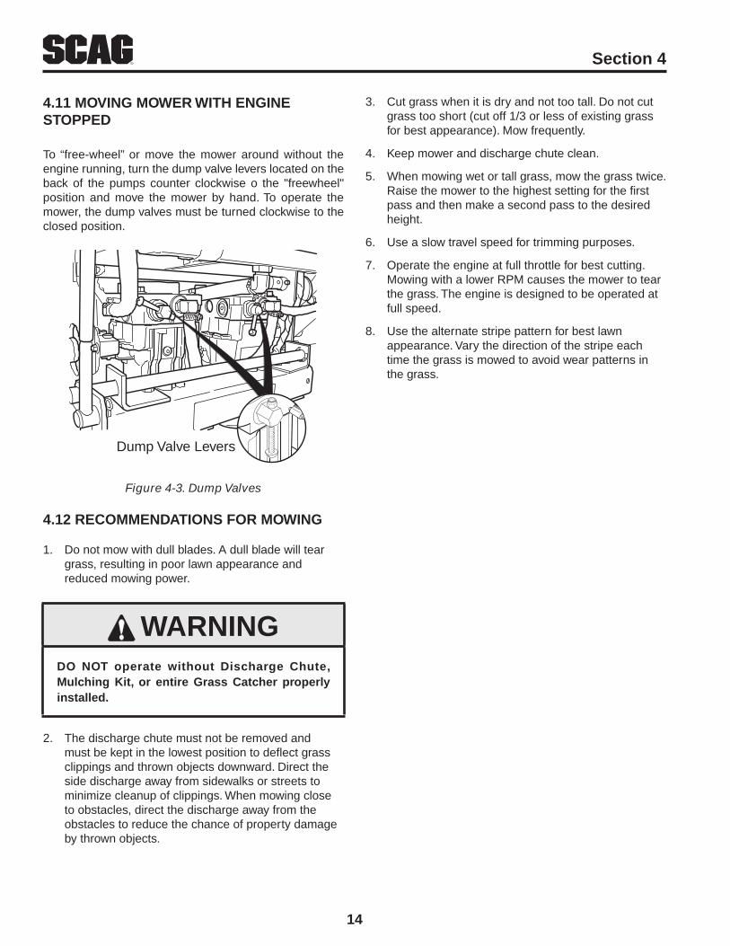
To “free-wheel” or move the mower around without the engine running, turn the dump valve levers located on the back of the pumps counter clockwise o the "freewheel" position and move the mower by hand. To operate the mower, the dump valves must be turned clockwise to the closed position.
Dump Valve Levers
Dump ValvesFigure 4-3.
RECOMMENDATIONS FOR MOWING4.12
Do not mow with dull blades. A dull blade will tear 1. grass, resulting in poor lawn appearance and reduced mowing power.
WARNINGDO NOT operate without Discharge Chute, Mulching Kit, or entire Grass Catcher properly installed.
The discharge chute must not be removed and 2. must be kept in the lowest position to deflect grass clippings and thrown objects downward. Direct the side discharge away from sidewalks or streets to minimize cleanup of clippings. When mowing close to obstacles, direct the discharge away from the obstacles to reduce the chance of property damage by thrown objects.
Cut grass when it is dry and not too tall. Do not cut 3. grass too short (cut off 1/3 or less of existing grass for best appearance). Mow frequently.
Keep mower and discharge chute clean.4.
When mowing wet or tall grass, mow the grass twice. 5. Raise the mower to the highest setting for the first pass and then make a second pass to the desired height.
Use a slow travel speed for trimming purposes.6.
Operate the engine at full throttle for best cutting. 7. Mowing with a lower RPM causes the mower to tear the grass. The engine is designed to be operated at full speed.
Use the alternate stripe pattern for best lawn 8. appearance. Vary the direction of the stripe each time the grass is mowed to avoid wear patterns in the grass.

15
RSection 5
CONDITION CAUSE CURE
STRINGERS - OCCASIONAL BLADES OF UNCUT GRASS
Width of Deck
SGB020
Low engine RPM Run engine at full RPM
Ground speed too fast Slow speed to adjust for conditions
Wet grass Cut grass after it has dried out
Dull blades, incorrect sharpening Sharpen blades
Deck plugged, grass accumulation Clean underside of deck
Belts slipping Adjust belt tension
STREAKING - STRIPS OF UNCUT GRASS IN CUTTING PATH
Width of Deck
SGB018
Dull, worn blades Sharpen blades
Incorrect blade sharpening Sharpen blades
Low engine RPM Run engine at full RPM
Belt slipping Adjust belt tension
Deck plugged, grass accumulation Clean underside of deck
Ground speed too fast Slow speed to adjust for conditions
Wet grass Cut grass after it has dried out
Bent blades Replace blades
STREAKING - STRIPS OF UNCUT GRASS BETWEEN CUTTING PATHS
Width of
Deck
Width of
DeckSGB019
Not enough overlapping between rows Increase the overlap of each pass
TROUBLESHOOTING CUTTING CONDITIONS
16
R Section 5
CONDITION CAUSE CURE
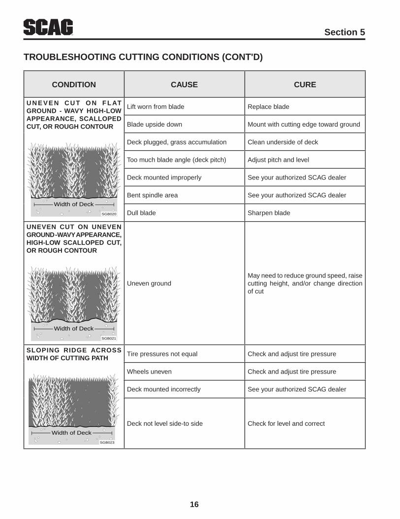
U N E v E N C U T O N F L AT GROUND - WAvY HIGH-LOW APPEARANCE, SCALLOPED CUT, OR ROUGH CONTOUR
Width of Deck
SGB020
Lift worn from blade Replace blade
Blade upside down Mount with cutting edge toward ground
Deck plugged, grass accumulation Clean underside of deck
Too much blade angle (deck pitch) Adjust pitch and level
Deck mounted improperly See your authorized SCAG dealer
Bent spindle area See your authorized SCAG dealer
Dull blade Sharpen blade
UNEvEN CUT ON UNEvEN GROUND - WAvY APPEARANCE, HIGH-LOW SCALLOPED CUT, OR ROUGH CONTOUR
Width of Deck
SGB021
Uneven groundMay need to reduce ground speed, raise cutting height, and/or change direction of cut
SLOPING RIDGE ACROSS WIDTH OF CUTTING PATH
Width of Deck
SGB023
Tire pressures not equal Check and adjust tire pressure
Wheels uneven Check and adjust tire pressure
Deck mounted incorrectly See your authorized SCAG dealer
Deck not level side-to side Check for level and correct
TROUBLESHOOTING CUTTING CONDITIONS (CONT'D)

17
RSection 5
CONDITION CAUSE CURE
SCALPING - BLADES HITTING DIRT OR CUTTING vERY CLOSE TO THE GROUND
Width of Deck
SGB022
Low tire pressures Check and adjust pressures
Ground speed too fast Slow speed to adjust for conditions
Cutting too lowMay need to reduce ground speed, raise cutting height, change direction of cut, and/or change pitch and level
Rough terrainMay need to reduce ground speed, raise cutting height, and/or change direction of cut
Ground speed too fast Slow speed to adjust for conditions
Wet grass Cut grass after it has dried out
STEP CUT - RIDGE IN CENTER OF CUTTING PATH
Width of Deck
SGB024
Blades not mounted evenly Adjust pitch and level
Bent blade Replace blade
Internal spindle failure See your authorized SCAG dealer
Mounting of spindle incorrect See your authorized SCAG dealer
SLOPE CUT - SLOPING RIDGES ACROSS WIDTH OF CUTTING PATH
Width of Deck
SGB025
Bent spindle mounting area See your authorized SCAG dealer
Internal spindle failure See your authorized SCAG dealer
Bent deck housing See your authorized SCAG dealer
TROUBLESHOOTING CUTTING CONDITIONS (CONT'D)

18
R Section 6
PARKING BRAKE ADJUSTMENT6.1
Adjust the parking brake so that when the brake 1. hand lever is against the stop on the handle bar, the brake levers on the brake shaft weldment are against the stops on the engine deck.
CAUTIONAdjust the brake only enough to hold the machine. Excessive force may cause damage to the machine or brake components.
Adjust the brake actuator rod on either side of the 2. machine to obtain proper brake adjustment.
NEUTRAL ADJUSTMENT6.2
-NOTE-
Neutral has been set by your Scag dealer at the time of set up and normally does not need to be adjusted. If, however, you find that the neutral has come out of adjustment, follow the procedure below.
Raise the drive wheels off the ground and block the 1. caster wheels to prevent the machine from moving.
Make sure the speed control lever is in neutral, 2. the steering control levers are in the neutral latch position, and the parking brake is on. Start the engine.
Release the parking brake and note if the tires are 3. rotating.
Start on the left side of the machine, using the 4. adjustment wrench located on the left side of the machine. Rotate the tracking adjustment nut counter clockwise just until the LH wheel starts to creep forward. Make note of the position of the adjustment nut. Repeat on the right side as needed. See Figure 6-1.
Turn the adjustment nut clockwise just until the 5. wheel turns rearward. Make note of the position of the adjustment nut. To adjust neutral, split the difference between the two noted positions of the adjustment nut. Repeat on the right side as needed.
Place the wrench in the holder on the left side of the 6. machine and turn the engine off.
ADJUSTMENTS
Neutral AdjustmentFigure 6-1.
STEERING CONTROL ROD 6.3 ADJUSTMENTS
-NOTE-
This adjustment is made to allow the steering control levers to be moved out of the neutral latch without engaging reverse
Before making this adjustment be sure that the speed control bearing is just touching the speed control cam and that the bellcrank bearing is resting in the center groove of the neutral cam.
Remove the speed control spring. Remove the 1. steering control rod swivel hair pin. Check the location of the swivel in the slotted hole in the bellcrank.
Turn the swivel joint on the steering control rods 2. until the swivel joint is centered in the slot in the bellcrank..
SLOW
FAST
TRACKING
ADJUSTMENT
SEE OPERATOR'S
MANUAL
390s0198-1
Control Rod AdjustmentFigure 6-2.
Reinstall the speed control spring onto the swivel. 3. Install the hair pin onto the swivel. See Figure 6-2.
19
RSection 6
TRACKING ADJUSTMENT6.4
-NOTE-
Before proceeding with this adjustment, be sure that the tire pressures are correct and the neutral adjustment and the steering control rod adjustment have been completed.
With the machine on a flat level surface, start the 1. engine, release the parking brake and place the speed control lever into the speed that will most often be used.
Squeeze the steering control levers and release the 2. neutral latch. Slowly release the steering control levers, allowing the machine to move forward.
WARNINGBefore attempting to make any tracking adjustments, move the speed control lever to the neutral position, place the blade engagement switch in the off position, apply the parking brake, and move the steering control levers into the neutral position.
If the machine pulls to one side, stop the mower 3. by placing the steering control levers in the neutral position. Using the adjustment wrench located on the left side of the machine, turn the tracking adjustment nut on the slower side counter clockwise until the machine tracks straight.
Bring the steering control levers back to the neutral 4. lock position and check to see that the machine does not creep forward on the adjusted wheel.
If the machine creeps in neutral, you have moved out 5. of the neutral band and will have to turn the tracking adjustment nut clockwise until the machine does not creep.
Repeat steps 1 and 2. If the machine continues 6. to pull to one side, stop the mower by placing the steering control levers in the neutral position. Turn the tracking adjustment nut on the faster side clockwise until the machine tracks straight.
If tracking cannot be acheived, contact your Scag 7. servicing dealer.
Tracking AdjustmentFigure 6-3.
THROTTLE CONTROL AND CHOKE 6.5 ADJUSTMENTS
These adjustments must be performed by your Scag dealer to ensure proper and efficient running of the engine. Should either need adjustment, contact your authorized Scag service center.
CUTTER DECK BELT ADJUSTMENTS6.6
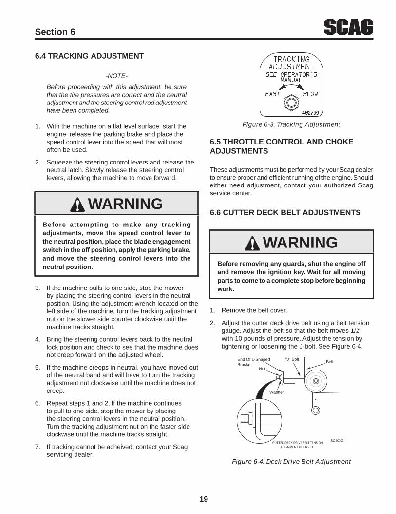
WARNINGBefore removing any guards, shut the engine off and remove the ignition key. Wait for all moving parts to come to a complete stop before beginning work.
Remove the belt cover.1.
Adjust the cutter deck drive belt using a belt tension 2. gauge. Adjust the belt so that the belt moves 1/2" with 10 pounds of pressure. Adjust the tension by tightening or loosening the J-bolt. See Figure 6-4.
Nut
"J" BoltBeltEnd Of L-Shaped
Bracket
Washer
SC400GCUTTER DECK DRIVE BELT TENSIONALIGNMENT IDLER - L.H.
Deck Drive Belt AdjustmentFigure 6-4.

20
R Section 6
-NOTE-
Due to initial belt stretch and to prevent the belt from slipping, check this adjustment after the first 2 hours, 4 hours and 8 hours of operation.
Adjust the RH blade drive belt using a belt tension 3. gauge. Adjust the belt so that the belt moves 1/2" with 10 pounds of pressure. Adjust the tension by tightening or loosening the J-bolt. See Figure 6-5 and Figure 6-6.
WASHER
NUT
SC401G
BELT
Cutter Deck Belt Adjustment R.H.Figure 6-5.
DISCHARGEAREA
BELT TENSIONADJUSTMENT IDLER
SC402G Rev.2
CHECK BLADE DRIVEBELT TENSION HERE
Cutter Deck BeltFigure 6-6.
BELT ALIGNMENT6.7
Belt alignment is important for proper performance of your Scag mower. If you experience frequent belt wear or breakage, see your authorized Scag service center for belt adjustment.
ADJUSTING CUTTING HEIGHT6.8
The mower deck can be adjusted from a height of 1-3/4 inches to 4-1/4 inches at 1/4-inch intervals.
Due to many cutting conditions that exist, it is difficult to suggest a cutter deck setting that will work for every lawn. There are two adjustments that can be made to the cutter deck, pitch and height.
PITCH is the angle of the blades (comparing front to rear).
HEIGHT is the nominal distance the blade is off of the ground. This measurement is made with the blades pointed side to side and distance is measured between the cutting tip and ground. (Also see Blade Height Adjustment).
Changes to the cutting height can be acheived by repositioning the cutter deck. (This adjustment will also effect the pitch of the deck). There are three available positions. See Figure 6-7.
Caster spacers also can be repositioned to change the cutting heights and to change the pitch of the cutter deck. See Figure 6-8.
SC405G-08
LOW CUT (1-3/4" to 3")
HIGH CUT (3-1/4" to 4-1/2")
MID RANGE(2-1/2" to 3-3/4")
Adjusting Cutting HeightFigure 6-7.
Pin
Spacers
2003SGB005
Caster Wheel SpacersFigure 6-8.

21
RSection 6
BLADE HEIGHT ADJUSTMENT
Adjusting the blade height can be done by moving any number of the five smaller 1/4" spacers on the blade mounting bolts to the top of the spindle shaft or below the spindle shaft.
-NOTE-
All blades should be positioned equally.
WARNINGBlades have a sharp cutting edge. Wear proper eye protection and protective gloves or wrap the blades with protective material when removing, sharpening and installing blades.
For best cut and discharge, a minimum of three spacers should be installed between the blade and the spindle. See Figure 6-9.
2002 SC407G
Blade SpacersFigure 6-9.
CUSTOM-CUT BAFFLE ADJUSTMENT
The Custom-Cut Baffle is designed to deliver optimum airflow and superior cutting performance in any type of grass. The Custom-Cut Baffle can be raised or lowered to precisely tailor the deck's performance for the type of grass being cut. The baffle can be set in seven (7) different positions for optimum performance.
A. 3-1/2" or 3-3/4" Position - (See Figure 6-10). For very tall, wiry or tough-to-cut grass.
B. 4" (factory setting), 4-1/4" or 4-1/2" Position - (See Figure 6-10). For general purpose cutting. This gives the best mix of cutting performance in all types of grass.
C. 4-3/4" or 5-1/4" Position - (See Figure 6-10). Placing the baffle in either the 4-3/4" or 5-1/4" setting will enhance fall cutting (leaf pickup) and reduce cutter deck "blowout".
To adjust the Custom-Cut Baffle height:
Place the cutter deck in the transport position.1.
Remove the hardware securing the Custom-Cut 2. Baffle to the cutter deck.
- NOTE -
Hardware location used in the illustrations are for reference only. Location of hardware may vary depending on cutter deck size.
Move the Custom-Cut Baffle to desired position. 3. (See Figures 6-10).
Reinstall the mounting hardware. Torque hardware to 4. 39 ft-lbs.

22
R Section 6
1 234
AB
1 23 4
AB
Custom-Cut Baffle Adjustment
Mounting Slot Selected Mounting Hardware LocationSlot “A” Hole 1 Hole 2 Hole 3 Hole 4Height (inches) 3-3/4” 4-1/4” 4-3/4” 5-1/4”
Slot “B” Hole 2 Hole 3 Hole 4Height (inches) 3-1/2” 4” 4-1/2”
Custom-Cut Baffle AdjustmentFigure 6-10.
23
RSection 6
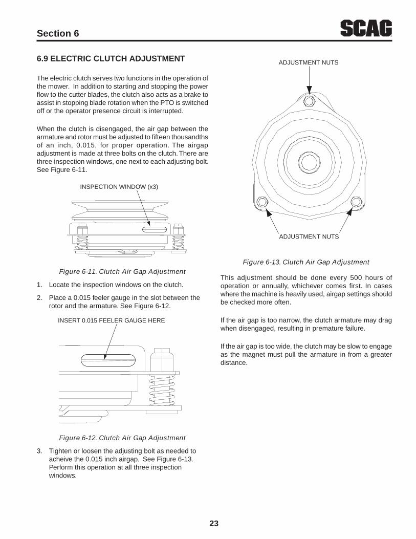
ELECTRIC CLUTCH ADJUSTMENT6.9
The electric clutch serves two functions in the operation of the mower. In addition to starting and stopping the power flow to the cutter blades, the clutch also acts as a brake to assist in stopping blade rotation when the PTO is switched off or the operator presence circuit is interrupted.
When the clutch is disengaged, the air gap between the armature and rotor must be adjusted to fifteen thousandths of an inch, 0.015, for proper operation. The airgap adjustment is made at three bolts on the clutch. There are three inspection windows, one next to each adjusting bolt. See Figure 6-11.
INSPECTION WINDOW (x3)
Clutch Air Gap AdjustmentFigure 6-11.
Locate the inspection windows on the clutch.1.
Place a 0.015 feeler gauge in the slot between the 2. rotor and the armature. See Figure 6-12.
INSERT 0.015 FEELER GAUGE HERE
Clutch Air Gap AdjustmentFigure 6-12.
Tighten or loosen the adjusting bolt as needed to 3. acheive the 0.015 inch airgap. See Figure 6-13.Perform this operation at all three inspection windows.
ADJUSTMENT NUTS
ADJUSTMENT NUTS
Clutch Air Gap AdjustmentFigure 6-13.
This adjustment should be done every 500 hours of operation or annually, whichever comes first. In cases where the machine is heavily used, airgap settings should be checked more often.
If the air gap is too narrow, the clutch armature may drag when disengaged, resulting in premature failure.
If the air gap is too wide, the clutch may be slow to engage as the magnet must pull the armature in from a greater distance.

24
R Section 7
MAINTENANCE CHART - RECOMMENDED SERvICE INTERvALS7.1
HOURS
PROCEDURE COMMENTSBREAK-IN (FIRST 10)
8 20 40 100 200 500
X Check all hardware for tightness
XCheck a l l be l t s fo r p rope r alignment
See paragraph 7.6
X Check engine oil level See paragraph 7.3
X *Clean mower
X Check tire pressure See paragraph 7.8
X *Clean air filter element See paragraph 7.5
X Check condition of blades See paragraph 7.7
X Sharpen cutter blades See paragraph 7.7
X Check tire pressure See paragraph 7.10
X Check belt tension See paragraph 6.3
XCheck the operator inter lock system
See paragraph 4.2
X Change engine oil and filter See paragraph 7.3
XGrease spindle bearings
XCheck belts for proper alignment See paragraph 7.6
XCheck a l l be l t s fo r p rope r alignment
X*Replace engine air filter See eng ine opera to r ' s
manual
X Grease caster wheel bearings See paragraph 7.2
X Check hydraulic system oil level See paragraph 7.3
X Check all hardware for tightness
X Change engine oil See paragraph 7.4
XGrease brake lever and brake actuator levers
See paragraph 7.2
X *Clean air cleaner element See paragraph 7.5
* Perform these maintenance procedures more frequently under extreme dusty or dirty conditions
MAINTENANCE

25
RSection 7
MAINTENANCE CHART - RECOMMENDED SERvICE INTERvALS (CONT'D)
HOURS
PROCEDURE COMMENTSBREAK-IN (FIRST 10)
8 40 100 200 500
X Check hardware for tightness
X Change engine oil filter See paragraph 7.4
X Replace engine fuel filter See paragraph 7.5
XGrease caster wheel pivot shafts
See paragraph 7.2
XDrain hydraulic system and replace oil and filter
See paragraph 7.3
X Adjust electric PTO clutch See paragraph 6.6
LUBRICATION7.2
GREASE FITTING LUBRICATION CHART
LOCATION LUBRICATION INTERvAL LUBRICANTNO. OF
PLACES
1 - Caster Wheel Pivot 100 Hours / Bi-Weekly Chassis Grease 2
2 - Caster Wheel Bearings 100 Hours / Monthly Chassis Grease 2
3 - Brake Actuator Levers 100 Hours / Bi-Weekly Chassis Grease 2
4 - Cutter Deck Spindles 40 Hours / Weekly + US Lithium MP White Grease 2 / 3
5 - Pump Control Pivot 100 Hours / Monthly Chassis Grease 2
6 - Brake Lever 100 Hours / Bi-Weekly Chassis Grease 1
7 - Neutral Cam Pivot 200 Hours / Monthly Chassis Grease 2

26
R Section 7
Lubrication Fitting Points Figure 7-1. 390S0177
GREASE FITTING LUBRICATION
LUBRICANT / INTERVAL
LITHIUM MP WHITE GREASE 2125( 40 HOURS / WEEKLY )
CHASSIS GREASE( 100 HOURS / BI-MONTHLY )
CHASSIS GREASE( 200 HOURS / MONTHLY )
4
4
1
23
7
6
7
1
2 3
5
5

27
RSection 7
Hydraulic OilDrain Cap
2003SWZ-Oil Drain
Filter Head
Hydraulic OilFilter
Hydraulic Oil Filter and Drain PlugFigure 7-2.
Re-install the drain plug into the tee fitting and be 3. sure it is tight.
- NOTE -
Before refilling the hydraulic oil reservoir the hydraulic oil filter should be changed as outlined in Procedure C "Changing Hydraulic Oil Filter Element".
Fill the reservoir to 2" inches from the top of the filler 4. neck with 20W50 motor oil.
Replace the reservoir fill cap. Start the engine and 5. drive forward and backward for two minutes. Check the oil level in the reservoir. If necessary, add oil to the reservoir.
C. CHANGING HYDRAULIC OIL FILTER ELEMENT
The hydraulic oil filter should be changed after every 500 hours of operation or annually, whichever occurs first.
Remove the oil filter element and properly discard it. 1. See Figure 7-2. Fill the new filter with clean oil and install the filter. Hand tighten only.
Run the engine at idle speed with the speed control 2. lever in neutral for five minutes.
Check the oil level in the hydraulic tank. It must be 3. 2" inches from the top of the filler neck. If necessary, add SAE 20W50 motor oil.
HYDRAULIC SYSTEM7.3
A. CHECKING HYDRAULIC OIL LEvEL
The hydraulic oil level should be checked after the first 8 hours of operation. Thereafter, check the oil after every 200 hours of machine operation or monthly, whichever occurs first.
- IMPORTANT -
If the oil level is consistently low, check for leaks and correct immediately.
Wipe dirt and contaminants from around the 1. reservoir cap. Remove the cap from the hydraulic oil reservoir.
Visually check the level of hydraulic oil. Hydraulic 2. oil must be at least 2" inches from top of the filler neck. If the level cannot be determined visually, use a clean tape measure to check the level. If the fluid is low, add 20W50 motor oil. DO NOT overfill; (overfilling the oil reservoir may cause oil seepage around the cap area).
Clean the fill cap and install it onto the reservoir.3.
B. CHANGING HYDRAULIC OIL
The hydraulic oil should be changed after every 500 hours or annually, whichever occurs first. The oil should also be changed if the color of the fluid has become black or milky. A black color and/or a rancid odor usually indicates possible overheating of the oil, and a milky color usually indicates water in the hydraulic oil.
- IMPORTANT -
The hydraulic oil should be changed if you notice the presence of water or a rancid odor to the hydraulic oil.
Park the mower on a level surface and stop the 1. engine.
Place a suitable container under the hydraulic oil 2. drain. Remove the fill cap from the reservoir. Remove the drain cap from the tee fitting located on the hydraulic system filter head. See Figure 7-2. Allow the fluid to drain into the container and properly discard it.
28
R Section 7
Extinguish all cigarettes, cigars, pipes and other 1. sources of ignition.
Use only an approved gasoline container.2.
Never remove the gas cap or add fuel with the 3. engine running. Allow the engine to completely cool before fueling.
Never fuel the machine indoors or in an enclosed 4. trailer.
Never store the machine or fuel container where 5. there is an open flame, spark or pilot light such as on a water heater or other appliances.
Never fill containers inside a vehicle or on a truck 6. or trailer bed with a plastic liner. Always place containers on the ground away from your vehicle before filling.
Remove the machine from the truck or trailer and 7. fuel on the ground. If this is not possible, then refuel the machine with a portable container, rather than from a gasoline dispenser nozzle.
Keep the nozzle in contact with the rim of fuel tank 8. or container opening at all times until fueling is complete. Do not use a nozzle lock-open device.
If fuel is spilled on clothing, change clothing 9. immediately and wash affected skin.
Replace gas cap and tighten securely.10.
B. REPLACING IN-LINE FUEL FILTER ELEMENTS
The engine fuel filter should be replaced after every 500 hours of operation or annually, whichever occurs first.
Close the shut-off valve.1.
Remove and replace the engine fuel filter. Open the 2. fuel shut-off valve.
ENGINE OIL7.4
A. CHECKING ENGINE CRANKCASE OIL LEvEL
The engine oil level should be checked after every 8 hours of operation or daily as instructed in the Engine Operator’s Manual furnished with this mower.
B. CHANGING ENGINE CRANKCASE OIL
After the first 20 hours of operation, change the engine crankcase oil and replace the oil filter. Thereafter, change the engine crankcase oil after every 100 hours of operation or bi-weekly, whichever occurs first. Refer to the Engine Operator’s Manual furnished with this mower for instructions.
C. CHANGING ENGINE OIL FILTER
After the first 20 hours of operation, replace the engine oil filter. Thereafter, replace the oil filter after every 200 hours of operation or every month, whichever occurs first. Refer to Engine Operator’s Manual for instructions.
ENGINE FUEL SYSTEM7.5
DANGERTo avoid injury from burns, allow the mower to cool before removing the fuel tank cap and refueling.
A. FILLING THE FUEL TANK
Fill the fuel tank at the beginning of each operating day to within one (1) inch below the bottom of the filler neck. Do not overfill. Use clean, fresh unleaded gasoline with a minimum octane rating of 87 and a maximum of 10% Ethanol.
DO NOT use E85 Fuel. Using E85 Fuel will cause severe damage to the engine.
To avoid personal injury or property damage, use extreme care in handling gasoline. Gasoline is extremely flammable and the vapors are explosive.

29
RSection 7
ENGINE AIR CLEANER7.6
A. CLEANING AND/OR REPLACING AIR CLEANER ELEMENT
For any air cleaner, the operating environment dictates the air cleaner service periods. Inspect and clean the air cleaner element after every 100 hours of operation or bi-weekly, whichever occurs first and replace the element if required.
- NOTE -
In extremely dusty conditions it may be necessary to check the element once or twice daily to prevent engine damage.
Remove the air cleaner cover. Set aside.1.
Remove the air cleaner and inspect.2.
Clean or replace the air cleaner and foam 3. pre-cleaner as recommended by the engine manufacturer.
Replace the air cleaner cover and secure.4.
BATTERY - ELECTRIC START MODELS7.7
WARNINGLead-acid batteries produce flammable and explosive gases. To avoid personal injury when checking, testing or charging batteries, DO NOT use smoking materials near batteries. Keep arcs, sparks and flames away from batteries. Provide proper ventilation and wear safety glasses.
WARNINGBattery posts, terminals, and related accessories contain lead and lead compounds, chemicals known to cause cancer and reproductive harm. Wash hands after handling.
WARNINGElectric storage battery fluid contains sulfuric acid which is POISON and can cause SEvERE CHEMICAL BURNS. Avoid contact of fluid with eyes, skin, or clothing. Use proper protective gear when handling batteries. DO NOT tip any battery beyond 45° angle in any direction. If fluid contact does occur, follow first aid suggestions below.
BATTERY ELECTROLYTE FIRST AID
External Contact — Flush with water.
Eyes — Flush with water for at least 15 minutes and get medical attention immediately.
Internal — Drink large quantities of water. Follow with Milk Of Magnesia, beaten egg, or vegetable oil. Get medical attention immediately. In case of internal contact, DO NOT give fluids that would induce vomiting.
A. CHARGING THE BATTERY
Refer to the battery charger’s manual for specific instructions.
Under normal conditions the engine’s alternator will have no problem keeping a charge on the battery. If the battery has been completely discharged for a long period of time, the alternator may not be able to recharge the battery, and a battery charger will be required.
DO NOT charge a frozen battery. It may explode and cause injury. Let the battery warm before attaching a charger.
Whenever possible, remove the battery from the mower before charging and make sure the electrolyte covers the plates in all cells.
WARNINGBATTERIES PRODUCE ExPLOSIvE GASES. Charge the battery in a well ventilated space so gases produced while charging can dissipate.

30
R Section 7
Charging rates between 3 and 50 amperes are satisfactory if excessive gassing or spewing of electrolyte does not occur or the battery does not feel excessively hot (over 125°F). If spewing or gassing occurs or the temperature exceeds 125°F, the charging rate must be reduced or temporarily stopped to permit cooling.
B. JUMP STARTING
The booster battery must be a 12 volt type. If a 1. vehicle is used for jump starting, it must have a negative ground system.
When connecting the jumper cables, connect the 2. positive cable to the positive battery post, then connect the negative cable to the negative battery post.
CUTTER BLADES7.8
A. BLADE INSPECTION
Remove the ignition key before servicing the blades.1.
Raise the mower deck to the highest position. Place 2. the lanyard pin in the highest cutting height position to prevent the cutter deck from falling.
WARNINGAlways wear proper hand and eye protection when working with cutter blades.
Check the cutter blades for straightness. If the cutter 3. blades appear bent, they will need to be replaced.
WARNINGDo not attempt to straighten a bent blade, and never weld a broken or cracked blade. Always replace it with a new blade to assure safety.
If a blade cutting edge is dull or nicked, it should be 4. sharpened. Remove the blades for sharpening. See "Blade Replacement."
- NOTE -
Keep the blades sharp. Cutting with dull blades not only yields a poor mowing job, but slows the cutting speed of the mower and causes extra wear on the engine and the blade drive by pulling hard.
B. BLADE SHARPENING
- NOTE -
If possible, use a file to sharpen the blade. Using a wheel grinder may burn the blade.
- NOTE -
DO NOT sharpen the blades beyond 1/3 of the width of the blade. See Figure 7-3.
Sharpen the cutting edge at the same bevel as the 1. original. See Figure 7-3. Sharpen only the top of the cutting edge to maintain sharpness.
SGB033
Angle Blade Back
Do Not Cut In
X Must NOT Exceed1/3 Blade Width
x
30
Blade SharpeningFigure 7-3.
Check the balance of the blade. If the blades are out 2. of balance, vibration and premature wear can occur. See your authorized Scag dealer for blade balancing or special tools, if you choose to balance your own blades.

31
RSection 7
C. BLADE REPLACEMENT
WARNINGAlways wear proper hand and eye protection when working with cutter blades.
Remove the ignition key before replacing the blades.1.
Remove the belt cover.2.
Secure the cutter blades to prevent them from 3. rotating, (use the optional Blade Buddy tool P/N 9212, to assist in securing the cutter blades), remove the blade attaching bolt. Remove the cutter blade, bolt, lockwasher and flatwasher from the spindle shaft. See Figure 7-4.
- NOTE -
Be sure that the blade is installed with the lift wing towards the top of the cutter deck.
Install the cutter blade on to the cutter spindle shaft. 4. Secure the blades from rotating and torque to 75 ft/lbs. See Figure 7-4.
Install the belt cover.5.
WASHERHEX HEAD BOLT
CUTTERBLADE
SPINDLE ASSEMBLY
CUTTER BLADESPACERS
HEX HEADBOLT / NUT
CUTTERDECK
SPINDLESHAFT
HEX NUT-TORQUETO 75 LB-FT
Blade ReplacementFigure 7-4.
TIRES7.9
Check the tire pressures after every 8 hours of operation or daily.
Caster Wheels Flat-Free Drive Wheels 12 PSI

32
R Section 8
SCAG APPROvED ATTACHMENTS AND ACCESSORIES.8.1
Attachments and accessories manufactured by companies other than Scag Power Equipment are not approved for use on this machine.
Scag approved attachments and accessories:
Mulch Plate (p/n 9258, 9286, 9287)•
Hurricane Mulch (p/n 9263, 9283, 9284)•
GC-4D (p/n 9054)•
GC-F4 (p/n 9055)•
Blade Buddy (p/n 9212)•
Hour Meter (p/n 48023•
Turbo Baffle (p/n 424208)•
ILLUSTRATED PARTS LIST
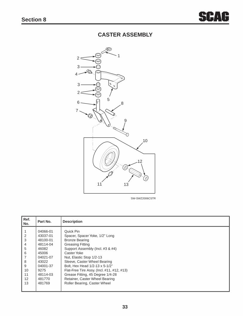
33
RSection 8
Ref. No.
Part No. Description
CASTER ASSEMBLY
1 04066-01 Quick Pin2 43037-01 Spacer, Spacer Yoke, 1/2" Long3 48100-01 Bronze Bearing4 48114-04 Greasing Fitting5 46082 Support Assembly (Incl. #3 & #4)6 45006 Caster Yoke7 04021-07 Nut, Elastic Stop 1/2-138 43022 Sleeve, Caster Wheel Bearing9 04001-37 Bolt, Hex Head 1/2-13 x 5-1/2"10 9275 Flat-Free Tire Assy. (Incl. #11, #12, #13)11 48114-03 Grease Fitting, 45 Degree 1/4-2812 481770 Retainer, Caster Wheel Bearing13 481769 Roller Bearing, Caster Wheel
1 2
3
4
3
2
6 5
8
9
7
10
SW-SWZ2006CSTR
12
1311
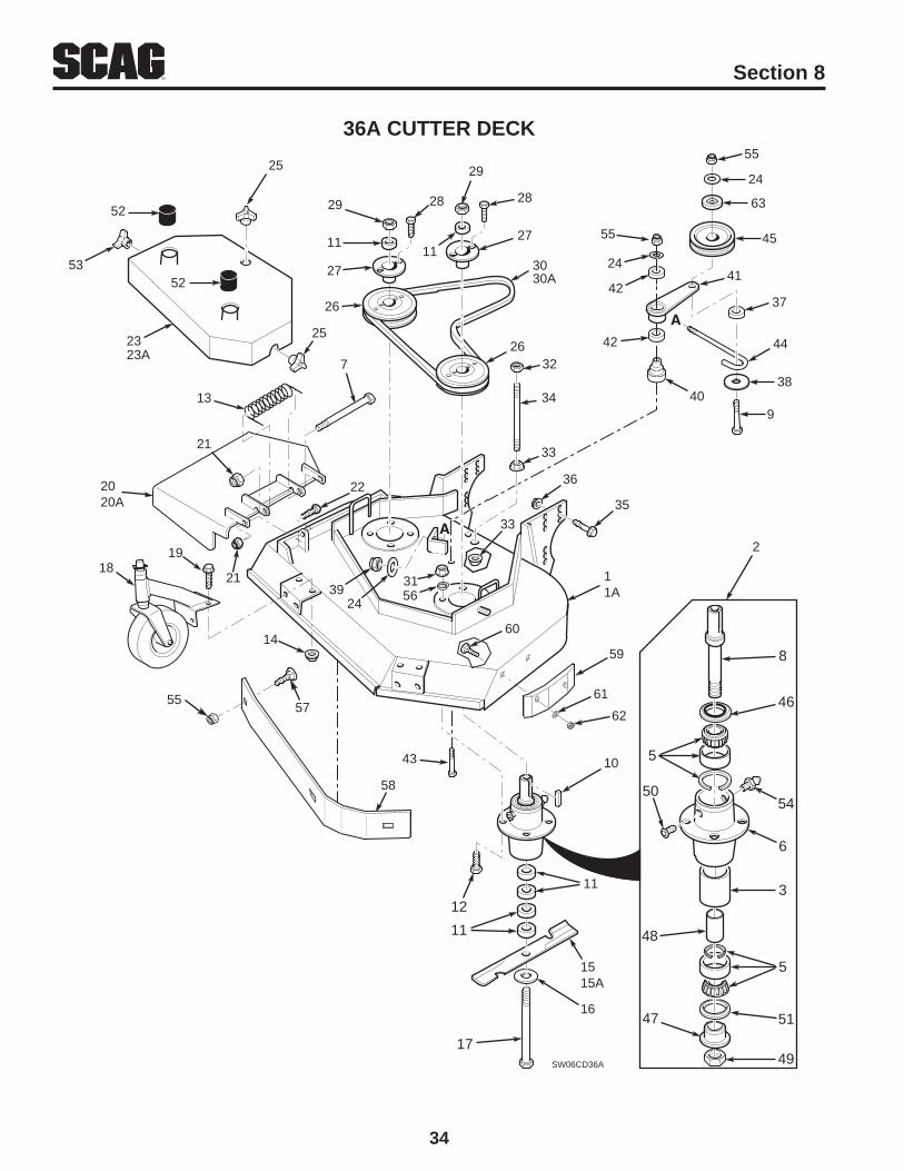
34
R Section 8
36A CUTTER DECK
2118
14
11A
2020A
22
29
11
27
26
28
29
27
30
28
11
32
31
26
34
36
35
33
33
SW06CD36A
2325
53
2
8
46
5
54
3
49
47
6
50
51
48
5
A
2439
11
10
17
16
1515A
12
11
13
21
7
30A
23A
52
52
19
5755
58
56
25
43
59
60
61
62
42
24
42
A
9
44
41
38
37
45
24
55
40
63
55

35
RSection 8
36A CUTTER DECK
Ref. No.
Part No. DescriptionRef. No.
Part No. Description
1235678910111213141515A161718192021222323A242526272829303132333435363738394041424344
461848461663433124810224364404001-1544358904001-5104063-084359204001-17548224504019-0348170748171104043-0604001-4146102304017-1646129504021-1004001-0946170946203004043-0404029-034827444892604001-17204020-094820404021-2204021-0504019-0404004-0204017-3604112-054327704041-1204021-09436814618414822404001-6244078
Cutter Deck w/DecalsCutter Spindle AssemblySpacer, OutsideBearing, TaperedSpindle HousingBolt, 5/16-18 x 4-3/4"Spindle ShaftBolt, 3/8-16 x 3-3/4" Hex HeadKey, 1/4 x 1/4 x 2"Spacer, Cutter Blade - SmallBolt, 5/16-18 x 1-1/2" Hex Head Grade 8Spring, Chute ReturnNut 5/16-18 Serrated FlangeCutter Blade, 18"Cutter Blade, 18 Hi-LiftFlatwasher, 5/8 WHex Hd. Bolt, 5/8-11 x 9-1/2"Caster AssemblyCpscrw,5/16-18 x 3/4" Ser.Flg. Hex HeadDischarge ChuteHex Nut, 5/16-18 Elastic StopHex Hd Bolt, 5/16-18 x 1"Belt Cover Assy (Incl. Decal)Belt Cover Assy (Incl. Decal)Flat Washer, 3/8" SpecialWing Nut, 3/8-16PulleyTapered HubHex Hd. Bolt, 1/4-20 x 1"Hex Nut, 5/8-11Belt, Blade DriveElastic Stop Nut, 5/16-18 Grade 8Hex Nut, 3/8-16 Center LocknutNut, 3/8-16 Serrated FlangeSupport, Belt CoverCpscrw, 1/2-13 x 1"Ser.Flg. HHNut, 1/2-13 SpiralockSpacer, J-HookFlatwasher, 3/8 x 1-1/2 x 16 GAElastic Stop Nut, 3/8-16Idler PivotIdler Arm Assy. (Inc. 42)BearingCpscrw, 3/8-16 x 3-1/4" Hex HeadJ-Hook
45464748495051525354555657585960616263
4832154810244329743296481035486774810254809804029-0448114-0404021-0904030-0304003-2342378348317404003-1204040-0404021-04424367
Idler Pulley, Belt ClutchSeal, Cutter SpindleSpindle BushingSpacer, InsideNut,1.06-18Relief Fitting, Cutter SpindleSeal, Cutter SpindleSpindle ShieldWing Nut, 3/8-16 (Small) RH sideGrease FittingNut, Hex Elastic Stop 3/8-16Lock Washer, 5/16"Bolt, Carriage 3/8-16 x 1"Baffle WeldmentPad, Deck WearBolt, Carriage 5/16-18 x 3/4"Flatwasher, 5/16"Hex Nut, 5/16-18 Center LocknutDust Shield
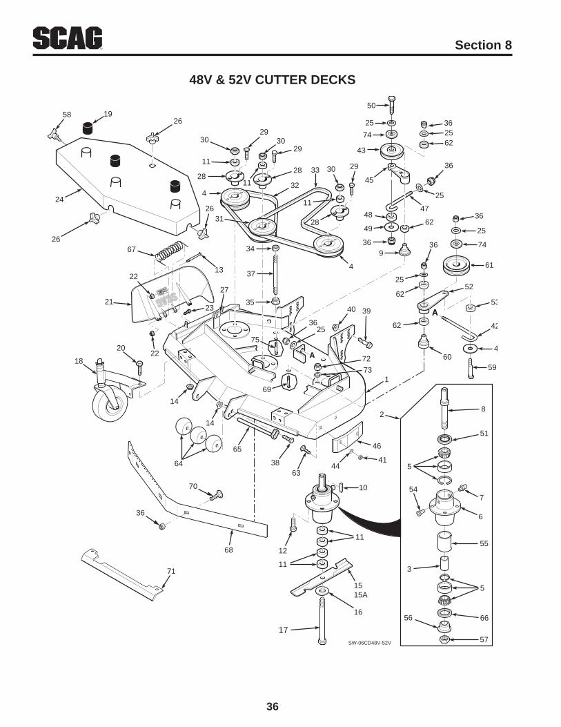
36
R Section 8
48v & 52v CUTTER DECKS
SW-06CD48V-52V
7
55
57
56
54
66
5
3
51
8
6
5
10
16
1515A
11
64
65
11
12
17
38
71
14
14
18 22
1
24
2634
37
35 40 39
30
11
28
4
2930
28
32
29
11
33
11
2930
28
4
49
36
62
45
2562
36
47
25
9
2536
2648
25
43
21
67
2213
A 72
31
2619
23
20
50
73
2
74
62
25
62
36
A
59
42
52
49
53
61
25
36
60
74
36
75
69
58
27
6344
41
46
68
70
36

37
RSection 8
48v & 52v CUTTER DECKS
Ref. No.
Part No. Description 48 52Ref. No.
Part No. Description 48 52
1
23456789101112
13
1415
15A
16
17
18192021
22
23
24
2526272829
303132
33
343536373839
4041
42
4344
461852461855461663432964827444810224364448114-04435894368204063-084359204001-175
04001-154
04019-0348170648170748171048171104043-06
04001-41
4610234809804017-1646184446184504021-10
04001-11
46186646186704043-0404029-0304110-034892604001-172
04020-0948274848087482854808948351804021-0504019-0404021-0904004-0204001-0904017-36
04112-0504021-04
44078430284818104040-04
Cutter Deck w/DecalsCutter Deck w/DecalsSpindle AssemblySpacer, InsidePulleyTapered BearingSpindle HousingGrease Fitting Str. 5/16"Spindle ShaftIdler PivotKey, 1/4 x 1/4 x 2"Spacer, Cutter Blade - SmallBolt, 5/16-18 x 1-1/2" Hex Head Gr. 8Bolt, 5/16-18 x 4-3/4" Hex HeadSerr. Flange Nut, 5/16-18Cutter Blade 16-1/2"Cutter Blade 18"Cutter Blade 16-1/2 Hi-LiftCutter Blade 18 Hi-LiftFlatwasher,5/8" (.688 x 1.75 x .134)Hex Head Bolt, 5/8-11 x 9-1/2"Caster AssemblySpindle ShieldCapscrew, 5/16-18 x 3/4"Discharge Chute 48VDischarge Chute 52VNut, 5/16-18 Elastic Elastic StopBolt, 5/16-18 x 1-1/2" Hex HeadBelt Cover (Incl. decals)Belt Cover (Incl. decals)Flat Washer, 3/8" SpecialWing Nut, 3/8-16 (Large)U-Nut, 3/8-16Tapered HubBolt, 1/4-20 x 1" Hex Head Grade 8Nut, 5/8-11 HexPulley, DoubleBelt, RH Blade DriveBelt, RH Blade DriveBelt, Blade DriveBelt, Blade DriveNut, 3/8-16, Nut CenterlockNut, 3/8-16, Serrated FlangeNut, 3/8-16 Elastic StopBolt, 5/16-18 x 1" Hex HeadBolt, 5/16-18 x 1" Hex HeadCpscrw, 1/2-13 x 1" Ser.Flg. HHNut, 1/2-13 SpiralockHex Nut, 5/16-18 Center LocknutJ-Hook, 48VJ-Hook, 52VIdler Pulley, “V” GrooveFlatwasher, 5/16"
x
xxxxxxxxxxx
x
xx
x
x
x
xxxx
x
x
x
xxxxx
xxx
x
xxxxxx
xx
x
xx
xxxxxxxxxxxx
x
x
x
xx
x
xxx
xx
x
xxxxxx
xx
x
xxxxxxx
xx
xxx
454647484950
5152535455
56575859
606162636465666768
69
707172737475
461091483176430284307704041-1204001-31
481024461841432774867743312
43297481035481625-0104001-51
436814832154822404003-124822954594448102548337842483942484004001-62
04003-2342397204021-2204030-0342436704001-22
Idler Arm Assy. (Incl. 62)Pad, Deck WearJ-Rod, Idler PulleySpacer, J-RodWasher, 3/8 x 1-1/2 x 16 ga.Bolt, 3/8-16 x 2-1/2" Hex HeadSeal, Cutter SpindleIdler Arm Assy (Includes 62)Spacer, J-Rod Reiief Fitting, Cutter SpindleSpacer, Outside, Cutter SpindleSpindle BushingNut, Cutter SpindleKnob, w/studBolt, 3/8-16 x 3-3/4" Hex HeadIdler PivotIdler Pulley, Belt ClutchBearingBolt, Carriage 5/16-18 x 3/4"Guide RollerRoller ShaftSeal, Cutter SpindleSpring, Chute ReturnBaffle Weldment 48VBaffle Weldment 52VBolt, 3/8-16 x 3-1/4" Hex HeadBolt, Carriage 3/8-16 x 1"HeatshieldNut, Hex Lock 5/16-18Lock Washer 5/16"Dust ShieldBolt, 3/8-16 x 2-3/4" Hex Head
xxxxxx
xxxxx
xxxx
xxxxxxxxx
x
xxxxxx
xxxxxx
xxxxx
xxxx
xxxxxxxx
xx
xxxxxx
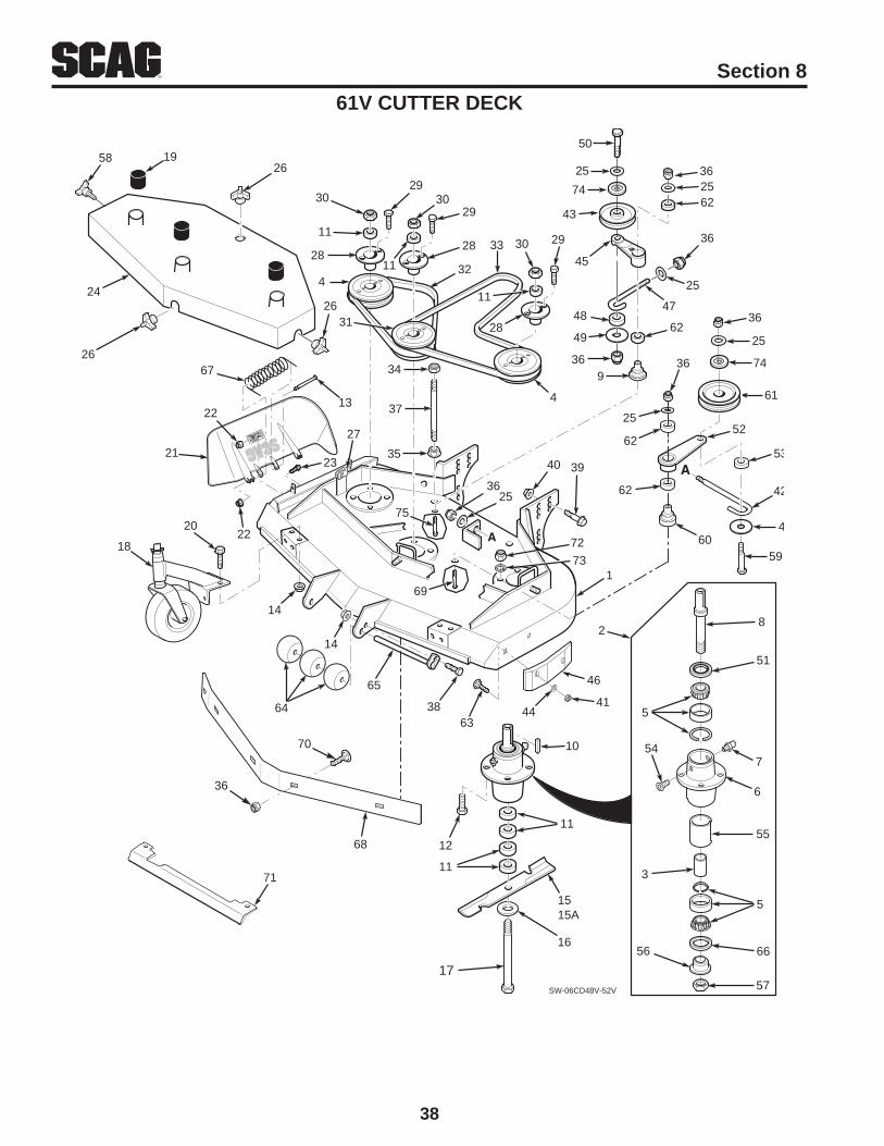
38
R Section 8
61v CUTTER DECK
SW-06CD48V-52V
7
55
57
56
54
66
5
3
51
8
6
5
10
16
1515A
11
64
65
11
12
17
38
71
14
14
18 22
1
24
2634
37
35 40 39
30
11
28
4
2930
28
32
29
11
33
11
2930
28
4
49
36
62
45
2562
36
47
25
9
2536
2648
25
43
21
67
2213
A 72
31
2619
23
20
50
73
2
74
62
25
62
36
A
59
42
52
49
53
61
25
36
60
74
36
75
69
58
27
6344
41
46
68
70
36

39
RSection 8
61v CUTTER DECK
Ref. No.
Part No. DescriptionRef. No.
Part No. Description
12345678910111213141515A1617181920212223242526272829303132333435363738394041424344
461860461663432964827454810224364448114-04435894368204063-084359204001-17504001-15404019-0348170848171204043-0604001-414610234809804017-1646184604021-1004001-1146186804043-0404029-0304110-034892604001-17204020-0948940482654808804021-0504019-0404021-0904004-0204001-0904017-3604112-0504021-04440784818104040-04
Cutter Deck w/DecalsSpindle AssemblySpacer, InsidePulleyTapered BearingSpindle HousingGrease Fitting Str. 5/16"Spindle ShaftIdler PivotKey, 1/4 x 1/4 x 2"Spacer, Cutter Blade - SmallBolt, 5/16-18 x 1-1/2" Hex Head Gr. 8Bolt, 5/16-18 x 4-3/4" Hex HeadSerr. Flange Nut, 5/16-18Cutter Blade 21"Cutter Blade 21" Hi-LiftFlatwasher,5/8" (.688 x 1.75 x .134)Hex Head Bolt, 5/8-11 x 9-1/2"Caster AssemblySpindle ShieldCapscrew, 5/16-18 x 3/4"Discharge Chute 61VNut, 5/16-18 Elastic Elastic StopBolt, 5/16-18 x 1-1/2" Hex HeadBelt Cover (Incl. decals)Flat Washer, 3/8" SpecialWing Nut, 3/8-16 (Large)U-Nut, 3/8-16Tapered HubBolt, 1/4-20 x 1" Hex Head Grade 8Nut, 5/8-11 HexPulley, DoubleBelt, RH Blade DriveBelt, Blade DriveNut, 3/8-16, Nut CenterlockNut, 3/8-16, Serrated FlangeNut, 3/8-16 Elastic StopBolt, 5/16-18 x 1" Hex HeadBolt, 5/16-18 x 1" Hex HeadCpscrw, 1/2-13 x 1" Ser.Flg. HHNut, 1/2-13 SpiralockHex Nut, 5/16-18 Center LocknutJ-Hook, 61VIdler Pulley, “V” GrooveFlatwasher, 5/16"
45464748495051525354555657585960616263646566676869707172737475
461091483176430284307704041-1204001-3148102446184143277486774331243297481035481625-0104001-51436814832154822404003-124822954594448102548337842484104001-6204003-2342397204021-2204030-0342436704001-22
Idler Arm Assy. (Incl. 62)Pad, Deck WearJ-Rod, Idler PulleySpacer, J-RodWasher, 3/8 x 1-1/2 x 16 ga.Bolt, 3/8-16 x 2-1/2" Hex HeadSeal, Cutter SpindleIdler Arm Assy (Includes 62)Spacer, J-Rod Reiief Fitting, Cutter SpindleSpacer, Outside, Cutter SpindleSpindle BushingNut, Cutter SpindleKnob, w/studBolt, 3/8-16 x 3-3/4" Hex HeadIdler PivotIdler Pulley, Belt ClutchBearingBolt, Carriage 5/16-18 x 3/4"Guide RollerRoller ShaftSeal, Cutter SpindleSpring, Chute ReturnBaffle Weldment 61VBolt, 3/8-16 x 3-1/4" Hex HeadBolt, Carriage 3/8-16 x 1"HeatshieldNut, Hex Lock 5/16-18Lock Washer 5/16"Dust ShieldBolt, 3/8-16 x 2-3/4" Hex Head

40
R Section 8
ENGINE DECK - MANUAL STARTENGINE DECK - MANUAL START
SWZ 08 EDMAN
10
8
9
6
87
5
4
2020A
25
14
13
1819
2121A
23
11
1212A
15
17
26
19
1
19
1616A
24
2
15
3
27
16 KAI17 KAI19 KAIONLY
22
24
28
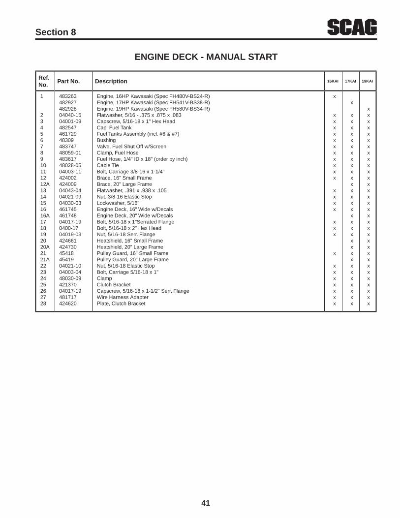
41
RSection 8
ENGINE DECK - MANUAL START
Ref. No.
Part No. Description 16KAI 17KAI 19KAI
1
2345678910111212A1314151616A1718192020A2121A22232425262728
48326348292748292804040-1504001-094825474617294830948374748059-0148361748028-0504003-1142400242400904043-0404021-0904030-0346174546174804017-190400-1704019-03424661424730454184541904021-1004003-0448030-0942137004017-19481717424620
Engine, 16HP Kawasaki (Spec FH480V-BS24-R)Engine, 17HP Kawasaki (Spec FH541V-BS38-R)Engine, 19HP Kawasaki (Spec FH580V-BS34-R)Flatwasher, 5/16 - .375 x .875 x .083Capscrew, 5/16-18 x 1" Hex HeadCap, Fuel TankFuel Tanks Assembly (incl. #6 & #7)BushingValve, Fuel Shut Off w/ScreenClamp, Fuel HoseFuel Hose, 1/4" ID x 18" (order by inch)Cable Tie Bolt, Carriage 3/8-16 x 1-1/4"Brace, 16" Small FrameBrace, 20" Large FrameFlatwasher, .391 x .938 x .105Nut, 3/8-16 Elastic StopLockwasher, 5/16"Engine Deck, 16" Wide w/DecalsEngine Deck, 20" Wide w/DecalsBolt, 5/16-18 x 1"Serrated FlangeBolt, 5/16-18 x 2" Hex HeadNut, 5/16-18 Serr. FlangeHeatshield, 16" Small FrameHeatshield, 20" Large FramePulley Guard, 16" Small FramePulley Guard, 20" Large FrameNut, 5/16-18 Elastic StopBolt, Carriage 5/16-18 x 1"ClampClutch BracketCapscrew, 5/16-18 x 1-1/2" Serr. FlangeWire Harness AdapterPlate, Clutch Bracket
x
xxxxxxxxxxx
xxxx
xxx
x
xxxxxxx
x
xxxxxxxxxxxxxxxxxxxxxxxxxxxxxxx
xxxxxxxxxxxxxxxxxxxxxxxxxxxxxxxx

42
R Section 8
ENGINE DECK - ELECTRIC STARTENGINE DECK - ELECTRIC STARTSWz-21KAE
SWZ 08 EDELCT
39
10
12
13
11
14
15
19
18
1626
38
17
36
34
37
35RED BLK8
9
6
87
5
4
3
41
2
2526
33
30
31
23 2229
28
20
21
41
40
27
32
26
1
26
24
30
28
30
42

43
RSection 8
ENGINE DECK - ELECTRIC START
Ref. No.
Part No. Description
123456789101112131415161718192021222324252627282930313233343536373839404142
48196404040-1504001-094825474617294830948374748059-0148361748028-05**04001-4404020-02480994239204029-014237464866104003-0104003-1142400904043-0404021-0946174804001-1704019-0304001-0804021-1004003-0448030-0942137004017-194541948029-0248029-144233084812604003-1242473004017-1904030-03424620
Engine, 21KAE Kawasaki (Spec FH641V-GS06-R) Flatwasher, 5/16-.375 x 875 x .083Capscrew, 5/16-18 x 1" Hex HeadCap, Fuel TankFuel Tank Assy. (incl. 6, 7)BushingValve, Fuel Shut Off w/ScreenClamp, Fuel HoseFuel Hose, 1/4 ID x 20" (order by inch)Cable TieBattery (Not Available Through Scag)Bolt, 1/4-20 x 1/2"Nut, 1/4-20PadBattery CoverWing Nut, 1/4-20Battery SupportPad, RubberBolt, 1/4-20 x 6" CarriageCarriage Bolt, 3/8-16 X 1-1/4"Brace, 20" Large FrameFlat Washer .391 x .938 x .105Nut, 3/8-16 Elastic StopEngine Deck, 20" Wide, w/decalsBolt, 5/16-18 x 2" Hex HeadNut, 5/16-18 Serr. FlangeHex Head Bolt, 5/16-18 x .75"Nut, 5/16-18 Elastic StopCarriage Bolt, 5/16-18 x 1"ClampClutch BracketCapScrw, 5/16-18 x 1.50" Serrated Flg.Pulley Guard, 20" FrameBattery Cable, 31.5" RedBattery Cable, 31.5" BlackBattery BoxRubber BootCarriage Bolt, 5/16-18 x .75"Heatshield, 20" Large FrameBolt, 5/16-18 x 1" Serrated Flg. Hex HeadLock Washer 5/16"Plate, Clutch Bracket

44
R Section 8
DRIvE AND BRAKE COMPONENTSDRIvE AND BRAKE COMPONENTS
50
47
50
24 24A
25
34 36
37 41
1
39
38
38
51
42
42
46
47
53
44
35
SWZ05D&BC
3, 3A
43
2
78
A
4
6
26
27
28
33
31
32
2930
2322
B5
B
54 55
56
57
58
59
60
56
17
12
13
15
14
16
20
1819
21
49
452
A
2
11
710, 10A
9
492
37
61
48
40

45
RSection 8
DRIvE AND BRAKE COMPONENTS
Ref. No.
Part No. Description 16KAI 17KAI 19KAI 21KAE
1233A4567891010A111213141516171819202122232424A25262728293031323334353637383940414243444546474849505152535455565758596061
48187604001-19458424585404062-0104003-124412604019-044341548114-05458604586104001-464816184818904222144867904028-0248150242221504008-014692848147004063-07481416485534858746139704041-2804030-0504102-0542253448030-0904021-1048171642253304001-1248275504001-1304021-054822446178304001-17248183504019-0304050-0204063-2904041-0748321348264948208504030-0404063-14435044303242271304001-5404001-16104043-0448187304001-5904021-0904019-0204001-151
Ring, SplitBolt, 3/8-16 x 1" Hex HeadBrake Shaft Assembly Weldment, 16" Small FrameBrake Shaft Assembly Weldment, 20" Large FrameHair Pin Cotter, .094 x 1.62Carrage Bolt, 5/16-18 x .75"Rod, Brake LowerNut, 3/8-16 Serr. FlangeBushing, BrakeGrease FittingBrake Actuator Weldment-LHBrake Actuator Weldment-RHBolt, 3/8-16 x 2-1/4"Tire, 16 x 6.50, 4 plyRim AssyLock Washer, Wheel MotorHex Castle Nut, 3/4-28 UNEFNut, LugWheel Assy., (incl. 12,13)Brake Drum1/2-20 Serrated BoltHub, WheelBrake Band, 7.5"Key, 3/16 X .75 WoodruffWheel MotorBelt, Pump Drive, 16" Small FrameBelt, Pump Drive, 20" Large FrameElectric ClutchFlat Washer .469 x 1.75 x .25Lock Washer, 7/16"Hex Head Bolt, 7/16-20 x 2-3/4"Plate, BackingClampNut, 5/16-18 Elastic StopRubber Pad, Clutch StopRetainer, Clutch StopHex Head Bolt, 5/16-18 x 1.75"Pulley, Pump Drive EngineHex Head Bolt, 5/16-18 x 2.75"Nut, 3/8-16 Center LockBall BearingsIdler Arm Weldment, Pump (incl. 38)Bolt, Hex Head 1/4-20 x 1" Grd 8Spring, Pump Belt IdlerNut, 5/16-18 Serr. FlangeRetaining Ring, 3/4" Ext. "E"Key, 1/4x1/4 x 3.75"Flat Washer, 3/8"Pulley, Idler 4.5"Pulley, Pump ShaftTapered HubLockwasher, 3/8"Key, 5.0 x 5.0 x 25mmPivot, Idler (Long)Swivel JointBase, Idler PivotBolt, Hex Head 3/8-16 x 3"Bolt, Hex Head 3/8-16 x 2.75"Flatwasher 3/8" ChainBolt, Hex Head 1/4-20 x 1.25"Nut, Hex Elastic Stop 3/8-16Nut, Serrated Flange 1/4-20Bolt, Hex Head 3/8-16 x 2.63"
xxx
xxxxxxxxxxxxxxxxxxxxxx
xxxxxxxxxxxxxxxxxxxxxxxxxxxxxxxxxxxxx
xxx
xxxxxxxxxxxxxxxxxxxxxx
xxxxxxxxxxxxxxxxxxxxxxxxxxxxxxxxxxxxx
xxxxxxxxxxxxxxxxxxxxxxxxxxxxxxxxxxxxxxxxxxxxxxxxxxxxxxxxxxxxxxxx
xx
xxxxxxxxxxxxxxxxxxxxxx
xxxxxxxxxxxxxxxxxxxxxxxxxxxxxxxxxxxxxx

46
R Section 8
HANDLE ASSEMBLY - 16" SMALL FRAME
87
15
8
2
76
5
34
1
20
2324
26
30
34
3432
3
37
36
61
39
67
38
37
35
40
37
38
3
11 27
9
2119
17
14
13
11
18
19
28
10
42
12
40
SWZ08SFHAN
40
60
75
82
61
86
8580
81
8879
B
76
99
65
98
73
93
78
79B
95
58
63
48
61
88
37
66
52
8266
6
73
46
43
70
4445
51
42
4749
11
24
72
C
3
C33
78
53
97
84
57
92
100
64
9610
4154
77
58
65
74
91
7183
50
60
59
62
45 11
56
5529
94
69
44
45
89
90
15
16
16
11
68
A
22
16
24
25
31
A
SCAG
PO
WER E
QU
IPM
EN
T
101

47
RSection 8
HANDLE ASSEMBLY - 16" SMALL FRAME
Ref. No.
Part No. DescriptionRef. No.
Part No. Description
12345678910111213141516
17181920
2122232425262728293031323334353637383940414243444546474849505152
4619764267504062-02452824308604001-2048493-014809204014-0104021-0804021-1004010-014894604019-01483142451917451915483957482686486094612424612414871748316104032-0104040-1504021-1004001-1704001-5348316004030-044414148304004017-2748347004019-044414245156204012-02463354316604063-1304060-0604021-104822304017-1704019-03422795435364840904001-6948494-024352204041-08
Upper Handle Wlmt. W/DecalsQuadrant, Speed ControlHairpin, .094 x 1.19Lever, Speed AdjustmentBushing, Speed Adjustment LeverHex Head Bolt, 3/8-16 x 1.5"Ball PlungerKnob, Speed AdjustmentCapscrew, 1/4-20 x 3/4" FHHSNut, 1/4-20 Elastic StopNut, 5/16-18 Elastic StopScrew, #10-32 x 1/2" PW HDThrottle ControlNut, #10-32 Serr. FlangeBushingHandle, Oper. Presence-RHHandle, Oper. Presence-LHSwitch, Electric Clutch EngageWire Harness, Manual StartKey Switch, Manual Srt. (inc. Hdw)Neutral Latch-RHNeutral Latch-LHSwitch, Neutral InterlockPlug, HandlebarWasher, Curved SpringFlat WasherNut, 5/16-18 Elastic StopHex Head Bolt, 5/16-18 x 2"Hex Hd. Bolt, 5/16-18 x 2.5"Lever, Steering ControlLockwasher, 3/8 SpringRod, Steering ControlSpring, Operator PresenceCapscr., 3/8-16 x 1" Ser. FlangeSpringNut, 3/8-16 Serr. FlangeRod Speed ControlBellcrank, Speed ControlSetscrew, 1/4-28 x .25"Cam, Speed Control (incl. 37)Jackshaft, Speed ControlKey, 1/8 x 1/2" WoodruffRoll Pin, 3/16-.75Nut, Elastic Stop 3/8-16Flange, BearingCapscrew, 5/16-18 x 1" Serr. Flg.Nut, 5/16-18 Serrated FlangePlate, SideSpacer, Neutral BearingBearing, Speed Ctrl. BellcrankHex Head Bolt, 5/16-18 x 1-3/4"Spring, ReturnSpacer, Side PlateFlatwasher, .766 x 1.25 x .035
535455565758596061626364656667686970717273747576
7778798081828384858687888990919293949596979899100101
04063-0704001-5904001-194341504050-02482244674748114-0504050-0104001-0948341404017-0548243104041-0746174504001-1048231404001-1524223734352048100-064414448154546196446196504030-02430324414304001-454846404021-0904010-1204001-01432864616054871704020-144238764238754834242120304062-014241134412642227345111348187904021-0948829462069483609
Key, Woodruff, 3/16 x .75Bolt, Hex Head, 1/4-20 x 1.25"Bolt, Hex Head, 3/8-16 x 1"Bushing, BrakeClip, Retaining .750 diameterBearing, Ball Neutral ReturnCam, Neutral (incl. grease ftng.)Grease Fitting, 1/4-28 UNFRetaining Ring, 5/8"Hex Head Bolt, 5/16-18 x 1"Lever, Speed ControlBolt, Hex Head 1/4-20 x.75"Linkage AssemblyFlat Wshr., 15/16 x .3906 x 12 gaDeck, Engine 16" WideHex Head Bolt, 5/16-18 x 1.25"Choke ControlBolt, Hex Head 3/8-16 x 4.25"Plate, ThreadedSwivel Joint, Steering RodBushingRod, OffsetSwitch, Parking BrakeControl, LH (inc. bush. & decal)Control, RH (inc. bush. & decal)Lockwasher, 1/4"Swivel JointRod, Brake LeverHex Hd. Bolt, 3/8-16 x 2"Ball Joint, RH ThreadNut, 3/8-16 Elastic StopScrew #10-32 Sltd Hex Wshr HdBolt, 1/4-20 x .75"SpacerParking Brake Lever with GripSwitch, SafetyNut, 3/8-24Mounting Bracket, WrenchWrenchGrip, Parking BrakePlate, ThreadedHairpin, .094 x 1.62"Bracket, Choke Mtg.Rod, Lower BrakePlate, CouplerShaft, Pump ControlSpringNut, 3/8-16 Elastic StopBlock, Pump ControlKey Chain with KeysKey with Shroud

48
R Section 8
HANDLE ASSEMBLY - 20" LARGE FRAME
87
15
16
16
15
8
2
76
5
34
1
22
20
2324
26
30
34
3432
3
37
36
61
39
67
38
37
35
40
37
38
3
11 27
11
68
9
2119
17
14
13
11
18
19
28
16
24
25
31
10
42
12
40
SWZ 08 LFHAN
75
76
74
71
40
60
101
82
A
A
61
86
8580
81
8879
B
100
98
65
97
73
93
78
79B
94
58
63
48
61
88
37
66
52
8266
6
73
46
43
70
4445
51
42
4749
11
24
72
C
3
C33
78
53
96
84
57
92
99
64
9510
4154
77
58
65
102
91
10383
50
60
59
62
45 11
56
5529
4489
90
69
SCAG
PO
WER E
QU
IPM
EN
T
104

49
RSection 8
HANDLE ASSEMBLY - 20" LARGE FRAME
Ref. No.
Part No. DescriptionRef. No.
Part No. Description
12345678910111213141516
1718
19
20
2122232425262728293031323334353637383940414243444546474849505152
4619774267504062-02452824308604001-2048493-014809204014-0104021-0804021-1004010-014894604019-0148314245191745191648395748268648268748609487984612424612414871748316104032-0104040-1504021-1004001-1704001-5348316004030-044414148304004017-2748347004019-044414245156204012-02463354315504063-1304060-0604021-104822304017-1704019-03422795435364840904001-6948494-024352204041-08
Upper Handle Wlmt. W/DecalsQuadrant, Speed ControlHairpin, .094 x 1.19Lever, Speed AdjustmentBushing, Speed Adjustment LeverHex Head Bolt, 3/8-16 x 1.5"Ball PlungerKnob, Speed AdjustmentCapscrew, 1/4-20 x 3/4" FHHSNut, 1/4-20 Elastic StopNut, 5/16-18 Elastic StopScrew, #10-32 x 1/2" PW HDThrottle ControlNut, #10-32 Serr. FlangeBushingHandle, Oper. Presence-RHHandle, Oper. Presence-LHSwitch, Electric Clutch EngageWire Harness, Manual StartWire Harness, Electric StartKey Switch, Manual Srt. (inc. Hdw)Key Switch, Electric Srt. (inc. Hdw)Neutral Latch-RHNeutral Latch-LHSwitch, Neutral InterlockPlug, HandlebarWasher, Curved SpringFlat WasherNut, 5/16-18 Elastic StopHex Head Bolt, 5/16-18 x 2"Hex Hd. Bolt, 5/16-18 x 2.5"Lever, Steering ControlLockwasher, 3/8 SpringRod, Steering ControlSpring, Operator PresenceCapscr., 3/8-16 x 1" Ser. FlangeSpringNut, 3/8-16 Serr. FlangeRod Speed ControlBellcrank, Speed ControlSetscrew, 1/4-28 x .25"Cam, Speed Control (incl. 37)Jackshaft, Speed ControlKey, 1/8 x 1/2" WoodruffRoll Pin, 3/16-.75Nut, Elastic Stop 3/8-16Flange, BearingCapscrew, 5/16-18 x 1" Serr. Flg.Nut, 5/16-18 Serrated FlangePlate, SideSpacer, Neutral BearingBearing, Speed Ctrl. BellcrankHex Head Bolt, 5/16-18 x 1-3/4"Spring, ReturnSpacer, Side PlateFlatwasher, .766 x 1.25 x .035
5354555657585960616263646566676869707172737475767778798081828384858687888990919293949596979899100
101102103104
04063-0704001-5904001-194341504050-02482244674748114-0504050-0104001-0948341404017-0548243104041-0746174804001-1048231404001-152424134352048100-064829804021-0104010-0304030-02430324414304001-454846404021-0904010-1204001-01432864616054871704020-144238764238754834242120304062-014412642227345111348187904021-094882946196446196548154544144422373462069483609
Key, Woodruff, 3/16 x .75Bolt, Hex Head, 1/4-20 x 1.25"Bolt, Hex Head, 3/8-16 x 1"Bushing, BrakeClip, Retaining .750 diameterBearing, Ball Neutral ReturnCam, Neutral (incl. grease ftng.)Grease Fitting, 1/4-28 UNFRetaining Ring, 5/8"Hex Head Bolt, 5/16-18 x 1"Lever, Speed ControlBolt, Hex Head 1/4-20 x.75"Linkage AssemblyFlat Wshr., 15/16 x .3906 x 12 gaDeck, Engine 20" WideHex Head Bolt, 5/16-18 x 1.25"Choke ControlBolt, Hex Head 3/8-16 x 4.25"Fuse Holder - 21KAESwivel Joint, Steering RodBushingBlade Fuse, 20A - 21KAENut, #10-32 Elastic Stop - 21KAEScrew, #10-32 x 1.5" Phillips - 21KAELockwasher, 1/4"Swivel JointRod, Brake LeverHex Hd. Bolt, 3/8-16 x 2"Ball Joint, RH ThreadNut, 3/8-16 Elastic StopScrew #10-32 Sltd Hex Wshr HdBolt, 1/4-20 x .75"SpacerParking Brake Lever with GripSwitch, SafetyNut, 3/8-24Mounting Bracket, WrenchWrenchGrip, Parking BrakePlate, ThreadedHairpin, .094 x 1.62"Rod, Lower BrakePlate, CouplerShaft, Pump ControlSpringNut, 3/8-16 Elastic StopBlock, Pump ControlControl, LH (inc. bush. & decal)Control, RH (inc. bush. & decal)Switch, Parking BrakeRod, OffsetPlate, ThreadedKey Chain with KeysKey with Shroud

50
R Section 8
HYDRAULIC ASSEMBLY
HYDRAULIC ASSEMBLY
B
ED
F G
3
5
13
2018
12
B
5
6
7
29
22
25
1010
1919
21
27
26
2810
10
G
F
23
23
23
11
6 6
11
ED
22
23
13
12
15
32
C
1
2
3
5
9
4
14
2005SWZ-HA
24
11
1128
11
11
11
23
23
20
12
6
C
23A
A
3129
4
23
12
8
JH
30
33
16
1010
1919
17
33
30
2810
11
10
J
H
28

51
RSection 8
Ref. No.
Part No. Description
1 481164 Cap, Oil Reservoir2 461428 Oil Reservoir (With Fittings)3 482266-01 Elbow, 9/16 O-Ring x 3/8" Hose4 48811 Hose, 3/8" ID - 10-1/4" Long (Order By The Inch)5 48811 Hose, 3/8" ID - 7" Long (Order By The Inch)6 48603-06 O-Ring7 483097 Pump, PG-1JQQ-DY1X-XXXX (R.H.)8 483098 Pump, PG-1GQQ-DY1X-XXXX (L.H.)9 04003-11 Bolt, Carriage, 3/8-16 x 1.25"10 481265 Hose, Pump to Wheel Motor11 48603-02 O-Ring12 482266-03 Elbow, 7/16-20 O-Ring x 3/8" Hose 13 48811 Hose, 3/8" ID - 11" Long (Order By The Inch)14 482417 Oil Filter Base 15 482477 Tee, 3/8 O-Ring x JIC x 1/2" Hose 16 422794 Strap, Hydraulic Tank17 422793 Bracket, Hydraulic Tank18 04017-16 Capscrew, 5/16-18 x .75" Serr. Flange19 48603-04 O-Ring20 482266-01 Elbow, 9/16 O-Ring x 3/8" Hose21 04019-03 Nut, 5/16-18 Serr. Flange22 482305 Hose, Formed 1/2" ID23 48136-13 Clamp, .69 max dia.24 481507 Tube, Filler Neck25 461745 Engine Deck (16" Wide) with Decals - Small Frame 461748 Engine Deck (20" Wide) with Decals - Large Frame26 04019-04 Nut, 3/8-16 Serr. Flange27 48462-01 Oil Filter28 48485-01 Elbow, 45 Deg.-3/4-16 JIC Male x Male 3/4-16 O-Ring 29 48136-05 Clamp, .87 max di.30 04021-08 Nut, 1/4-2031 482202 Elbow, 3/4-16 O-Ring x 1/2" Hose32 48571-02 Cap, 3/4-1633 04010-10 Screw, 1/4-20 x 2.0" Round Head Phillips
HYDRAULIC ASSEMBLY

52
R Section 8
HYDRAULIC PUMP ASSEMBLY
Overhaul Seal K
it
1
2
3
4
5
67
8
9
10
28
24
26
11
12
1314
1522
23
20
21
1817
16
19
27
29
25
24
PORT "A"SIDE
PORT "B"SIDE

53
RSection 8
Ref. No.
Part No. Description
1 HG 70516 Housing Kit2 HG 70573 End Cap Kit3 HG 50641 Straight Headless Pin4 HG 50969 Hex Flange Bolt, M8-1.25 x 60mm5 HG 51232 Housing O-Ring6 HG 2513027 Charge Pump Kit7 HG 50273 Gerotor Assembly8 HG 9004101-1340 O-Ring9 HG 50095 Socket Head Screw, M6 x 1.0-20mm10 HG 2513030 Bypass Valve Kit11 HG 70521 Pumpshaft Kit12 HG 50315 Ball Bearing, 17 x 40 x 1213 HG 51161 Lip Seal14 HG 50329 Retaining Ring15 HG 50951 Spacer16 HG 70331 Cylinder Block Kit 17 HG 2003014 Block Spring18 HG 2003017 Block Thrust Washer19 HG 51444 Valve Plate20 HG 2003087 Swash Plate21 HG 50551 Ball Thrust Bearing 22 HG 2003005 Trunnion Arm23 HG 2000015 Slot Guide24 HG 2510062 Check Valve Kit (.024” Orfice) port “A” on Left Hand Pump, port “B” on Right Hand Pump25 HG 70403 Charge Relief Kit26 HG 2513043 Trunnion Seal with Retainer 27 HG 9005110-4400 Straight Thread Plug28 HG 50408 Straight Headless Pin29 HG 70525 Overhaul Seal Kit
HYDRAULIC PUMP ASSEMBLY
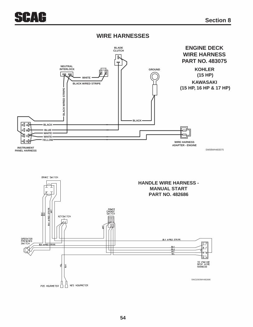
54
R Section 8
HANDLE WIRE HARNESS -MANUAL STARTPART NO. 482686
SWZ2003WH482686
SW08WH483075
WIRE HARNESSADAPTER - ENGINE
BLADECLUTCH
GROUND
BLACK
KOHLER (15 HP)
ENGINE DECKWIRE HARNESSPART NO. 483075
E A
F B
G C
H D
INSTRUMENTPANEL HARNESS
BLACK
BLUE
WHITEWHITE
YELLOW
NEUTRAL INTERLOCK
BL
AC
K W
/RE
D S
TR
IPE
BLACK W/RED STRIPE
WHITE
KAWASAKI (15 HP, 16 HP & 17 HP)
WIRE HARNESSES

55
RSection 8
WIRE HARNESSES
ENGINE DECKWIRING HARNESSKAWASAKI ELECTRIC START PART NUMBER: 483076
BLACK W/RED STRIPE
WHITE
TRANSMISSION
INSTRUMENTCONNECTOR
RED W/YEL STRIPE
RED
GREEN
BLACK
BLK W/RED STRIPE
WHITE
WHITE
BLUE
YELLOW
ENGINEGROUND
TO ENGINE
ELECTRICCLUTCH
SOLENOIDSTARTER
SOLENOID
BLACK
HANDLE WIRING HARNESSKAWASAKI ELECTRIC START PART NO. 482687

56
R Section 8
WIRE HARNESS ADAPTERPART NO. 481717
KAWASAKI(15 HP, 16 HP & 17 HP)
SW2006WH481717
WIRE HARNESSES

57
RSection 8
REPLACEMENT DECALS AND INFORMATION PLATES
1 2
3
9
5
WARNINGDO NOT OPERATE WITHOUT DISCHARGE CHUTE, MULCHING
KIT, OR ENTIRE GRASS CATCHER INSTALLED483405
SPINNING BLADESKEEP CLEAR
BLADE CONTACT & THROWNOBJECTS CAN INJURE
483407
WARNINGFALLING HAzARD
USE ONLY SCAG APPROvEDRIDING ATTACHMENTS
SEE OPERATOR'S MANUAL 483404
MOUNT RIDINGATTACHMENT
HERE WARNING
READ OPERATOR'S MANUAL 483402
INSTALL BELT COvERBEFORE OPERATING MACHINE
7
6
BEFORE OPERATING
483441
Read operator's manual
Solicite etiquetas en espanola un distribuidor Scag
Make sure guards, shields& safety devices are in place & working
Clear area of children,bystanders & debris
Mow across face of slopes
Trained operators only
WARNING
MANUFACTURED UNDER ONE OR MOREOF THE FOLLOWING PATENTS:
4,487,006 4,885,903 4,920,733 4,967,5434,991,382 4,998,948 5,042,239 5,117,6175,133,176 5,826,416 5,832,708 5,865,0186,192,666 6,766,633 6,892,519 6,996,9627,065,946 7,197,863 7,237,374 7,373,768
PATENTS PENDING
WARNING
* Keep hands, feet & clothing clear* Keep all guards in place* Shut off engine & disengage blade clutch before servicing* Use caution in directing discharge* Read instruction manual before operating
ROTATING BLADES AND BELTS
DO NOT OPERATE UNLESS GRASS CATCHER, MULCHING KIT ORDISCHARGE CHUTE IS INSTALLED
483406
4
48404
8

58
R Section 8
11
12
14
482297
13
Heavy-DutyCommercial
481971
15
REPLACEMENT DECALS AND INFORMATION PLATES
10
481423
SPEEDCONTROL
SLOW
FAST
NEUTRALN
481124

59
RSection 8
REPLACEMENT DECALS AND INFORMATION PLATES
Ref.No.
Part No. Description
1 483405 Decal, Discharge Chute2 48314 Decal, Scag Logo3 483407 Decal, Danger-Spinning Blades4 483406 Decal, Warning-Rotating Blades5 483044 Decal, Patents6 48404 Decal, Metalcraft - Made in USA7 483441 Decal, Instrument Panel - Rear8 483404 Decal, Sulky Attachment9 483402 Decal, Belt Cover10 481423 Decal, Instrument Panel - Front (SWZ-19KAI & SWZ-21KAE only)11 481483 Decal, Instrument Panel - Front12 482297 Decal, 36 Advantage13 483199 Decal, 48 Velocity Plus 483200 Decal, 52 Velocity Plus 483201 Decal, 61 Velocity Plis14 481971 Decal, Heavy Duty Commercial15 481124 Decal, Speed Control16 481942 Decal, Scag Zero Turn17 481425 Decal, Oil18 482799 Decal, Tracking Adjustment19 482816 Decal, Height of Cut** 461986 Spanish Decal Kit, Walk-Behinds (Not Shown)
482816 CUTTING HEIGHT ADJUSTMENT
TOP MIDDLE MIDDLEBOTTOMBOTTOMBOTTOM
NUMBER OF SPACERS ABOVE CUTTER BLADES 0 1 2 3 4 5
001234
- - - - -4-3/8
- - - - 44-1/8
2-3/82-5/82-3/4 -3-3/43-7/8
2-1/82-3/82-1/2 -3-1/23-5/8
1-7/82-1/82-1/42-7/83-1/43-3/8
1-5/81-7/8 22-5/8 33-1/8
DECK MOUNTING HOLE POSITIONNUMBER OF CASTER SPACERS (BELOW SUPPORT)
16
1918
SEEOPERATOR’S
MANUALOIL
17

LIMITED WARRANTY - COMMERCIAL EqUIPMENTAny part of the Scag commercial mower manufactured by Scag Power Equipment and found, in the reasonable judgment of Scag, to be defective in materials or workmanship, will be repaired or replaced by an Authorized Scag Service Dealer without charge for parts and labor during the periods specified below. This warranty is limited to the original purchaser and is not transferable. Proof of purchase will be required by the dealer to substantiate any warranty claims. All warranty work must be performed by an Authorized Scag Service Dealer.
This warranty is limited to the following specified periods from the date of the original retail purchase for defects in materials or workmanship:
Wear items including drive belts, blades, hydraulic hoses and tires are warranted for ninety (90) days.•Batteries are covered for ninety (90) days.•Frame and structural components including oil reservoir and oil coolers are warranted for 2 years (Parts and labor).•Cutter decks are warranted against cracking for a period of three (3) years. (Parts and labor 1st and 2nd year; Parts •
only 3rd year.) The repair or replacement of the cutter deck will be at the option of Scag Power Equipment. We reserve the right to request components for evaluation. This warranty does not cover any mower that has been subject to mis-use, neglect, negligence, or accident, or that has been operated in any way contrary to the operating instructions as specified in the Operator’s Manual.
Engines and electric starters are covered by the engine manufacturer’s warranty period.•Major drive system components are warranted for two (2) years by Scag Power Equipment. (Parts and labor) (Two •
year warranty exclude fittings, hoses, drive belts). The repair or replacement of the hydraulic pump or hydraulic mo-tor will be at the option of Scag Power Equipment. This warranty does not cover any mower that has been subject to misuse, neglect, negligence, or accident, or that has been operated in any way contrary to the operating instructions as specified in the Operator’s Manual.
Electric clutches have a Limited Warranty for 2 year (Parts and labor).•Spindle assemblies have a Limited Warranty for three years (Parts and labor 1st year and 2nd; Parts only 3rd year).•Any Scag product used for rental purposes is covered by a 90 day warranty.•
The Scag mower, including any defective part must be returned to an Authorized Scag Service Dealer within the warranty period. The expense of delivering the mower to the dealer for warranty work and the expense of returning it to the owner after repair will be paid for by the owner. Scag’s responsibility is limited to making the required repairs and no claim of breach of warranty shall be cause for cancellation or rescission of the contract of sale of any Scag mower.
This warranty does not cover any mower that has been subject to misuse, neglect, negligence, or accident, or that has been operated in any way contrary to the operating instructions as specified in the Operator’s Manual. The warranty does not apply to any damage to the mower that is the result of improper maintenance, or to any mower or parts that have not been assembled or installed as specified in the Operator’s Manual and Assembly Manual. The warranty does not cover any mower that has been altered or modified, changing performance or durability. In addition, the warranty does not extend to repairs made necessary by normal wear, or by the use of parts or accessories which, in the reasonable judgment of Scag, are either incompatible with the Scag mower or adversely affect its operation, performance or durability.
Scag Power Equipment reserves the right to change or improve the design of any mower without assuming any obligation to modify any mower previously manufactured. All other implied warranties are limited in duration to the two (2) year warranty period or ninety (90) days for mowers used for rental purpose. Accordingly, any such implied warranties including merchantability, fitness for a particular purpose, or otherwise, are disclaimed in their entirety after the expiration of the appropriate two year or ninety day warranty period. Scag’s obligation under this warranty is strictly and exclusively limited to the repair or replacement of defective parts and Scag does not assume or authorize anyone to assume for them any other obligation. Some states do not allow limitations on how long an implied warranty lasts, so the above limitation may not apply to you.
Scag assumes no responsibility for incidental, consequential or other damages including, but not limited to, expense for gasoline, expense of delivering the mower to an Authorized Scag Service Dealer and expense of returning it to the owner, mechanic’s travel time, telephone or telegram charges, rental of a like product during the time warranty repairs are being performed, travel, loss or damage to personal property, loss of revenue, loss of use of the mower, loss of time or inconvenience. Some states do not allow the exclusion or limitation of incidental or consequential damages, so the above limitation or exclusion may not apply to you. This warranty gives you specific legal rights, and you may also have other rights which vary from state to state.

GARANTÍA LIMITADA - EQUIPO COMERCIALToda pieza del cortacésped comercial Scag fabricada por Scag Power Equipment que, según criterio razonable de Scag, presentemateriales o mano de obra defectuosos será reparada o reemplazada por un distribuidor autorizado Scag sin cargo por las piezas ni manode obra durante los períodos especificados abajo. Esta garantía se limita al comprador original y no es transferible. Para acceder acualquier reclamo de garantía, el distribuidor requerirá el comprobante de compra. Todo trabajo bajo garantía debe realizarlo un distribuidorautorizado Scag.
Con respecto a materiales o mano de obra defectuosos, esta garantía se limita a los siguientes períodos especificados a partir de la fechade compra original:
* Los artículos desgastables, incluyendo correas de transmisión, cuchillas, mangueras hidráulicas y llantas, están garantizadospor noventa (90) días.* Las baterías están garantizadas por noventa (90) días.* El bastidor y los componentes estructurales, incluyendo el depósito de aceite y los enfriadores de aceite, tienen una garantía de2 años (Piezas y mano de obra).* Las plataformas de corte están garantizadas contra grietas por un período de tres (3) años. (Piezas y mano de obra, primer ysegundo año; piezas solamente, tercer año). La reparación o el reemplazo de la plataforma de corte estarán sujetos a discreciónde Scag Power Equipment. Nos reservamos el derecho de solicitar componentes para su evaluación. Esta garantía no cubreningún cortacésped que haya sido sometido a uso indebido, descuido, negligencia o accidente, o que se haya operado de maneradistinta a la especificada en el manual del operador.* Los motores eléctricos y los arrancadores están cubiertos por el período de garantía del fabricante de motor.* Los componentes principales del sistema de transmisión están garantizados por Scag Power Equipment por dos (2) años.(Piezas y mano de obra) (La garantía de dos años no incluye las conexiones, mangueras, las correas de transmisión). Lareparación o el reemplazo de la bomba hidráulica o el motor hidráulico estarán sujetos a discreción de Scag Power Equipment.Esta garantía no cubre ningún cortacésped que haya sido sometido a uso indebido, descuido, negligencia o accidente, o que sehaya operado de manera distinta a la especificada en el manual del operador.* Los embragues eléctricos tienen una Garantía limitada de 2 años (Piezas y mano de obra).* Los ensambles del eje tienen una Garantía limitada de 3 años (Piezas y mano de obra, primer y segundo año; piezassolamente, tercer año).* Cualquier producto Scag que se utilice para alquiler está cubierto por una garantía de 90 días.
El cortacésped Scag, incluida cualquier pieza defectuosa, debe ser llevado a un distribuidor autorizado de Scag dentro del período degarantía. Los gastos incurridos en la entrega del cortacésped al distribuidor para que se realice el trabajo bajo garantía, así como losgastos de devolución del cortacésped al propietario después de la reparación, estarán a cargo del propietario. La responsabilidad de Scagse limita a la realización de las reparaciones requeridas y ninguna reclamación por incumplimiento de las obligaciones de garantía serácausa de cancelación o revocación del contrato de venta del cortacésped Scag.
Esta garantía no cubre ningún cortacésped que haya sido sometido a uso indebido, descuido, negligencia o accidente, o quese haya operado de manera distinta a la especificada en el manual del operador. La garantía no será de aplicación en ningún casode daño ocasionado al cortacésped como consecuencia de mantenimiento inadecuado o a cualquier cortacésped o piezas que no se hayanensamblado o instalado de acuerdo con las especificaciones del manual del operador o el manual de montaje. La garantía no cubre ningúncortacésped que haya sufrido alteraciones o modificaciones que hayan afectado su funcionamiento o durabilidad. Asimismo, la garantía nose extiende a reparaciones necesarias por el desgaste normal o por el uso de piezas o accesorios que, según criterio razonable de Scag,sean incompatibles con el cortacésped Scag o afecten la operación, funcionamiento o durabilidad de éste.
Scag Power Equipment se reserva el derecho de modificar o mejorar el diseño de cualquier cortacésped sin tener por elloobligación alguna de modificar cualquier cortacésped fabricado con anterioridad. Cualquier otra garantía implícita se limita a unperíodo de garantía de dos (2) años o noventa (90) días en el caso de cortacéspedes destinados a alquiler. Por consiguiente, se rechaza ensu totalidad cualquier garantía implícita, incluidas las garantías de comerciabilidad, adecuación para un fin determinado, o de otro tipo,después de la finalización del correspondiente período de garantía de dos años o noventa días. La obligación de Scag en virtud de lapresente garantía se limita estricta y exclusivamente a la reparación o el reemplazo de piezas defectuosas, y Scag no asume ni autoriza aningún otro a asumir en su lugar ninguna otra obligación. La limitación antes mencionada no será de aplicación en aquellos estados en losque no esté permitida la limitación del período de validez de una garantía implícita.
Scag no asume responsabilidad alguna por daños incidentales, consecuentes ni de cualquier otro tipo, incluyendo, pero sin limitarse a, gastode gasolina, gasto de entrega del cortacésped a un distribuidor autorizado Scag y gasto de su devolución al propietario, tiempo de viaje delmecánico, cargos por comunicaciones telefónicas o telegramas, alquiler de un producto similar durante el período en que se llevan a cabolas reparaciones bajo garantía, viajes, pérdida o daño de bienes personales, lucro cesante, daños ocasionados por la pérdida del usodel cortacésped, daños por la pérdida de tiempo o cualquier otro inconveniente. La limitación o exclusión antesmencionada no será de aplicación en aquellos estados en los que no esté permitida la exclusión o limitación de dañosincidentales o consecuentes. La presente garantía le otorga derechos legales específicos, aparte de los derechos de losque usted goza, según el estado.

23
Rango de velocidad hacia adelante: 0 a 7.4 mph (11.8 Kph)Rango de velocidad en reversa: 0 a 3.0 mph (4.8 Kph)
PLATAFORMAS DE CORTESWM 36 Advantage, SWM 48 Velocity Plus,Velocity Plus SWM 52, Velocity Plus SWM 61
Tipo:Diseño delantero con rodillos amortiguadores del corte rasanteConstrucción:SWM36A, 48V: Acero calibre 7 con faldón de calibre 7 (3/16")
SWM52V, 61V: Acero calibre 10 con faldón calibre 7 (3/16")Ancho de corte:35.5" (90.2 cm), 48.0 (122.0 cm), 52.0 “ (132.0 cm),
61.0 “ (155.0 cm).Ajuste de altura de corteAjustable desde 1-3/4" a 4-1/4" en incrementos de 1/4"Cuchillas de corte:Marbain , .197 de grosor
SWM 36: Dos (2) 18"; SWM 48: Tres (3) 16.5"SWM 52: Tres (3) 18"
Accionamiento de las cuchillas:Embrague eléctrico de freno de cuchilla con interruptor de panel deinstrumentos
Abertura de descarga:Abertura de descarga extra ancha con tolva de descarga articuladaRuedas locas:Llantas macizas de 9 x 3.5 con flotación de la banda de rodadurasuave,rodamientos de rodillos y retiro rápido del pinEjes:Cuerpo fundido, rodamiento de rodillos cónicos, bajo mantenimiento
con conexión de grasa en la parte superior y cabezal móvil de aliviode exceso de grasa
Poleas del eje:Acero partido con cubos cónicos de fácil desmontajePolea guía:Polea de 5" de diámetro, de fabricación soldada y remachada,
Rodamientos OD de 1-3/8"Brazo de la polea:Brazo de polea para servicio pesado de canal de acero de 1/4"Correas de la plataforma de corte:Sección B, de Kevlar
ESPECIFICACIONES ADICIONALESARTÍCULOS/ACCESORIOS OPCIONALESRecogedor de césped de tela:Recogedor de césped GC-F4 con capacidad de 4 pies cúbicosRecogedor de césped de metal:Recogedor de césped GC-4D con capacidad de 4 pies cúbicos y
descarga por tirón de una cuerda o tipo recoger y descargar
Deflector turboDeflector de descarga de alta velocidad. Mejora la calidad del cortey la distribución de la descarga.
Equipo mezclador de paja Hurricane:El exclusivo sistema mezclador de paja Hurricane emplea lasplacas tipo “ojo de la tormenta” (eye of the hurricane) combinadocon deflectores en V empernados, directores de flujo, cuchillaseliminadoras y una placa de cierre de descarga lateral.
Sujetavasos:Permite al operador llevar en forma segura y práctica una bebida.
DIMENSIONES APROXIMADASSWZ-36ASWZ-48VSWZ-52VSWZ-61VLongitud:74.0"74"76"78.0"Longitud con el recogedor de césped:74.0"74"76"78.0"Ancho de alineación:37.0"37.0"37.0"41.0"Ancho:47.0"60.5"64.5"73.5"Ancho (con la tolva de descarga arriba):37.0"49.0"52"62.0"Ancho con recogedor de césped:55.0"69.0"71"80.0"Altura:40.5"40.5"40.5"40.5"Altura con recogedor de césped:40.5"40.5"40.5"40.5"Peso:515 lbs.565 lbs.585 lbs.717 lbs.Peso con recogedor de césped:555 lbs.605 lbs.625 lbs.757 lbs.Radio de giro:CeroCeroCeroCero
TM
ESPECIFICACIONES TÉCNICAS (CONTINUACIÓN)
TM
*Bastidor grande = Ancho de alineación - 41.0" Peso - 605 lbs.
Peso con recogedor de césped - 645 lbs.
*
Fecha de publicación: Abril de 2007
Especificaciones sujetas a cambio sin previo aviso
**

22
MODELOSSWZ36A-16KAI, SWZ48V-17KAI, SWZ52V-17KAI,SWZ52V-19KAI, SWZ-19KAI, SWZ-21KAE
MOTORESTipo general:Industrial de servicio pesado/ComercialMarca / Modelos:Kawasaki FH480V (16HP), FH541V (17HP), FH580V (19HP),
FH641V (21HP)Potencia:Kawasaki 16HP, 17HP, 19HP & 21HPTipo:Motores de eje vertical, 4 ciclos, gasolinaDesplazamiento:Kawasaki: 16HP=472cc, 17HP=585cc, 19HP=585cc,
21HP=675ccCilindros:V-TwinControlador:Controlador tipo mecánico con control de velocidad variable.Ajustes:Kawasaki 16HP, 17HP & 19HP = 3600 rpm (+/-100 rpm),
marcha en vacío puesa a 1550 rpm (+/-150 rpm),21HP= 3600 rpm (+/-75 rpm),marcha en vacío puesta a1550 rpm (+/-75 rpm)
Grupo de escape:Silenciador de tubo de escapeConjunto de bomba de combustible:Consulte las especificaciones del fabricanteConjunto de bomba de aceite:Consulte las especificaciones del fabricanteGrupo de válvula:Consulte las especificaciones del fabricanteArrancador/Sistema eléctrico:Encendido electrónico con arrancador de retroceso o batería
de 12 voltios con alternador, encendido de estado sólido conllave de arranque
Sistema de carga:Variado - Consulte las especificaciones del fabricante
PLATAFORMA DEL MOTOREspesor:Acero calibre 7Tanque de combustible:Polietileno sin costuras, 6 galones (19.0 litros) con sujetavasos.Ruedas motrices/Llantas:6x6.50-8 sin cámara neumática, de cuatro capas, borde radialFrenos:Frenado dinámico mediante sistema de transmisión hidráulicaEjes:1" cónicoBarras del mango:1-1/4" diámetro
SISTEMA DE TRANSMISIÓNTipo:Transmisión hidráulica con dos bombas de desplazamiento
variable y dos motores de hierro fundido y alto torque
Hidro bombas:Dos bombas Hydro-Gear BDP 10A con válvulas de descargapara el desplazamiento sin operación del motor
Motores de la rueda motriz:Dos motores de alto torque, hierro fundido, 12 pulgadas cúbicasGrupo de refrigeración de fluido hidráulico:depósito de refrigeración de nylon, con capacidad de 4 cuartos,
usa fluido SAE 20W50 y filtro de 10 micrones
Control de dirección/desplazamiento:Mangos de control independiente para cada rueda, apriete paramoverlo desde adelante a neutral y a reversa, palanca de bloqueode neutral, rango de velocidad controlado con palanca simple (dediseño patentado), ajuste de alineación en el campo conherramienta suministrada
Frenos de estacionamiento:Tambor de 7.5", freno de banda, uno en cada ruedaVálvulas de descarga:Permite el movimiento sin funcionamiento del motorEjes:ejes cónicos de motor de 1"Mazo de cables:Alambre calibre 14Grupo de seguridad:Sistema de presencia del operador de actuación manual (diseño
patentado), con embrague/cuchilla y bloqueo de transmisión paraapagar el motor
ESPECIFICACIONES TÉCNICAS
Fecha de publicación: Abril de 2007
Especificaciones sujetas a cambio sin previo aviso
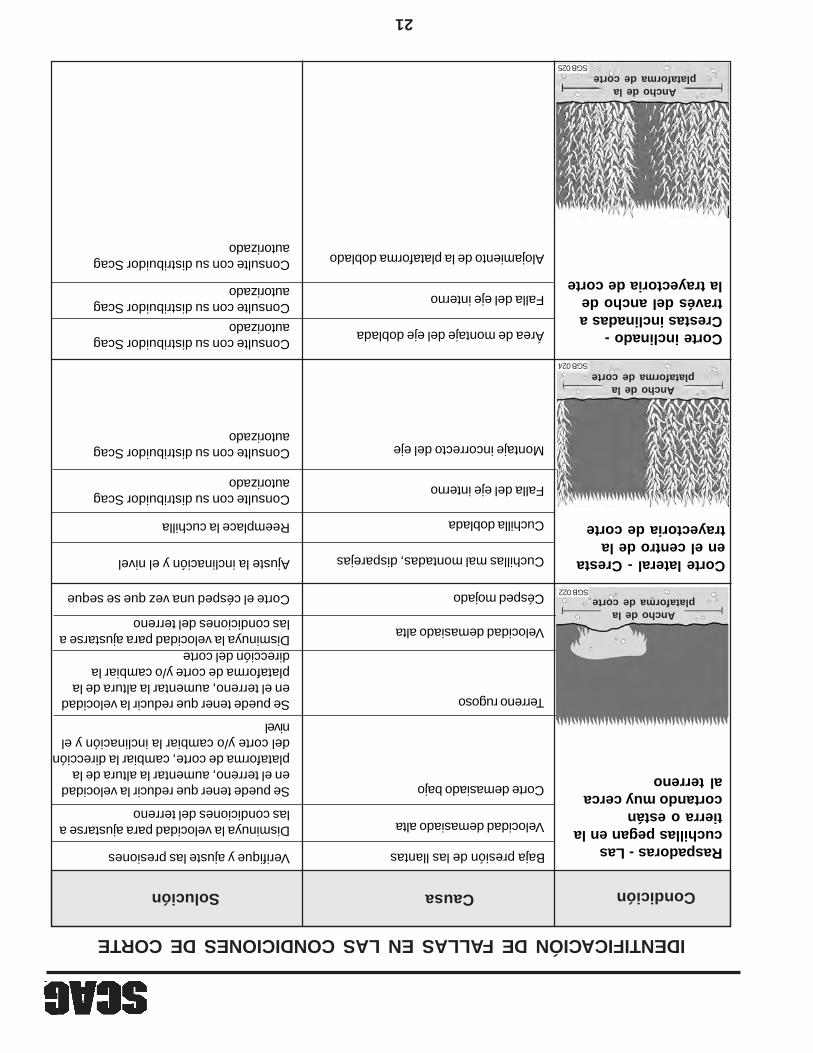
21
IDENTIFICACIÓN DE FALLAS EN LAS CONDICIONES DE CORTE
CondiciónCausaSolución
Raspadoras - Lascuchillas pegan en latierra o estáncortando muy cercaal terreno
Baja presión de las llantasVerifique y ajuste las presiones
Velocidad demasiado altaDisminuya la velocidad para ajustarse alas condiciones del terreno
Se puede tener que reducir la velocidaden el terreno, aumentar la altura de laplataforma de corte, cambiar la direccióndel corte y/o cambiar la inclinación y elnivel
Corte demasiado bajo
Se puede tener que reducir la velocidaden el terreno, aumentar la altura de laplataforma de corte y/o cambiar ladirección del corte
Terreno rugoso
Velocidad demasiado altaDisminuya la velocidad para ajustarse alas condiciones del terreno
Césped mojadoCorte el césped una vez que se seque
Corte lateral - Crestaen el centro de latrayectoria de corte
Cuchillas mal montadas, disparejasAjuste la inclinación y el nivel
Cuchilla dobladaReemplace la cuchilla
Falla del eje internoConsulte con su distribuidor Scagautorizado
Montaje incorrecto del ejeConsulte con su distribuidor Scagautorizado
Corte inclinado -Crestas inclinadas através del ancho dela trayectoria de corte
Área de montaje del eje dobladaConsulte con su distribuidor Scagautorizado
Falla del eje internoConsulte con su distribuidor Scagautorizado
Alojamiento de la plataforma dobladoConsulte con su distribuidor Scagautorizado
Ancho de laplataforma de corte
SGB 022
Ancho de laplataforma de corte
SGB 024
Ancho de laplataforma de corte
SGB 025

20
Condición
IDENTIFICACIÓN DE FALLAS EN LAS CONDICIONES DE CORTE
CausaSolución
Consulte con su distribuidor Scagautorizado
Salientes inclinadas a loancho de la trayectoriade corte
Llantas con presión desigualRevise y ajuste la presión de lasllantas
Revise y ajuste la presión de las llantas Ruedas disparejas
Plataforma de corte montadaincorrectamente
Consulte con su distribuidor Scagautorizado
Corte disparejo enterreno disparejo -Apariencia baja y altaondulada, cortevolado o perfilirregular
Se puede tener que reducir la velocidaden el terreno, aumentar la altura de laplataforma de corte y/o cambiar ladirección del corte
Terreno disparejo
Corte disparejo enterreno plano -Apariencia baja y altaondulada, corte voladoo perfil irregular
Levantador de la cuchilla desgastadoReemplace la cuchilla
Cuchilla montada invertidaMonte la cuchilla con el filo hacia elterreno
Césped acumulado debajo de laplataforma de corte
Limpie la parte de abajo de laplataforma
Demasiado ángulo en la cuchilla(inclinación de la plataforma de corte)Ajuste la inclinación y el nivel
Plataforma de corte montadaincorrectamente
Consulte con su distribuidor Scagautorizado
Área del eje doblada
Cuchilla desafiladaAfile la cuchilla
Ancho de laplataforma de corte
SGB 020
Ancho de laplataforma de corte
SGB 021
Ancho de laplataforma de corte
SGB 023
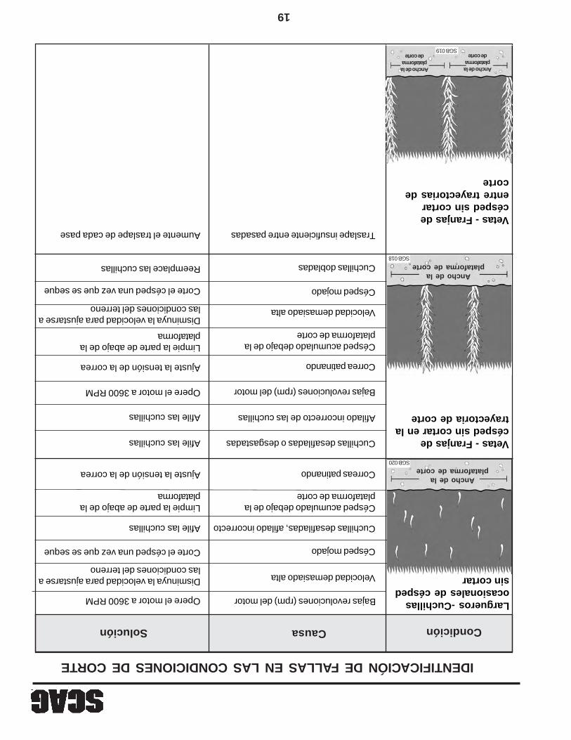
19
CondiciónCausaSolución
IDENTIFICACIÓN DE FALLAS EN LAS CONDICIONES DE CORTE
Largueros -Cuchillasocasionales de céspedsin cortar
Bajas revoluciones (rpm) del motorOpere el motor a 3600 RPM
Velocidad demasiado altaDisminuya la velocidad para ajustarse alas condiciones del terreno
Césped mojadoCorte el césped una vez que se seque
Cuchillas desafiladas, afilado incorrectoAfile las cuchillas
Césped acumulado debajo de laplataforma de corte
Limpie la parte de abajo de laplataforma
Correas patinandoAjuste la tensión de la correa
Vetas - Franjas decésped sin cortar en latrayectoria de corte
Cuchillas desafiladas o desgastadasAfile las cuchillas
Afilado incorrecto de las cuchillasAfile las cuchillas
Bajas revoluciones (rpm) del motorOpere el motor a 3600 RPM
Correa patinandoAjuste la tensión de la correa
Césped acumulado debajo de laplataforma de corte
Limpie la parte de abajo de laplataforma
Velocidad demasiado altaDisminuya la velocidad para ajustarse alas condiciones del terreno
Césped mojadoCorte el césped una vez que se seque
Cuchillas dobladasReemplace las cuchillas
Vetas - Franjas decésped sin cortarentre trayectorias decorte
Traslape insuficiente entre pasadasAumente el traslape de cada pase
Ancho de laplataforma de corte
SGB 020
Ancho de laplataforma de corte
SGB 018
Ancho de laplataforma
de corte
Ancho de laplataforma
de corteSGB 019

18
El líquido de la batería contiene ácido sulfúricoque es TÓXICO y puede causar GRAVESQUEMADURAS QUÍMICAS. Evite el contacto dellíquido con los ojos, la piel, o con la ropa. Useequipo de protección apropiado cuandomanipule baterías. NO INCLINE ninguna bateríamás de 45° en ninguna dirección. Si ocurrecontacto con el líquido, siga primero lassugerencias de primeros auxilios.
PRIMEROS AUXILIOS PARA ELECTROLITO DEBATERÍA
CONTACTO EXTERNO — Enjuague con agua.
OJOS — Enjuague con agua al menos durante 15minutos y obtenga atención médicainmediatamente.
INTERNO — Beba grandes cantidades de agua.Continúe con leche de magnesia, huevosbatidos, o aceite vegetal. Obtenga atenciónmédica inmediatamente. En caso de contactointerno, NO PROPORCIONE líquidos queinduzcan al vómito.
Carga de la batería
NO cargue una batería congelada. Puede estallar ycausar lesiones. Permita que la batería se entibie antesde conectar un cargador.
Siempre que sea posible, retire la batería del cortacéspedantes de cargarla.
Use ropa de protección y herramientas aisladas.
Desenchufe el cargador antes de conectarlo odesconectarlo de la batería. Consulte el manual delcargador de batería para instrucciones específicas.
Bajo condiciones normales el alternador del motor notendrá problemas para mantener la carga de la batería. Sila batería se ha descargado completamente por unperíodo largo de tiempo, el alternador puede no ser capazde recargarla, y se necesitará un cargador de baterías.
Las tasas de carga entre 3 y 50 amperios sonsatisfactorias si no provocan excesivos gases, si noarrojan demasiado electrolito o si la batería no está muycaliente (encima de 125º F). Si se produce derrame deelectrolito o excesiva producción de gas, o si latemperatura excede 52°C (125°F), la tasa de carga debereducirse o detenerse temporalmente para permitir elenfriamiento.
Arranque por puente
LAS BATERÍAS PRODUCEN GASES EXPLOSIVOS.Cargue la batería en un espacio bien ventiladode modo que se puede disipar los gasesproducidos durante la carga.
1.La batería auxiliar de arranque debe ser de 12 voltios.Si se usa un vehículo para el arranque por puente, debetener un sistema de tierra negativo.
2.Cuando conecte los cables del puente, conecte el cablepositivo al poste positivo de la batería y luego el cablenegativo al poste negativo de la batería.
LIMPIEZA DE LA MÁQUINA
1.Después que cada uso, lave el cortacésped y laplataforma de corte. Use agua fría y limpiadoresautomotrices. No use limpiadores a presión.
2.No rocíe los componentes eléctricos.
3.Repare las superficies de metal dañadas con la pinturade retoque Scag (N/P 48521) disponible en sudistribuidor autorizado Scag. Encere el cortacésped conuna cera automotriz para una máxima protección de lapintura.
No lave ninguna parte del equipo mientras estácaliente. No lave el motor; use aire comprimido.
ADVERTENCIA:ADVERTENCIA:
PRECAUCIÓN:

17
BATERÍA (SÓLO UNIDADES DE ARRANQUEELÉCTRICO)
Verificación del nivel de electrolito ylimpieza de Batería
Esta máquina viene equipada de fábrica con una bateríasellada. No se requiere mantenimiento para conservar elnivel de electrolito. La suciedad y el líquido acumuladossobre la batería pueden causar que la batería sedescargue. La corrosión de los terminales de la batería olas conexiones flojas ocasionarán un mal funcionamientode la misma.
1.Afloje las dos tuercas de mariposa plásticas y luegoretire la cubierta de la batería.
2.Limpie los extremos del cable y los postes de la bateríacon estropajo de acero. Use una solución de bicarbonatode soda y agua para limpiar la batería. No permita quela solución se introduzca a las celdas de la batería.
3.Apriete firmemente las conexiones del cable y apliqueuna capa ligera de grasa dieléctrica de silicona a losterminales para evitar la corrosión.
4.Instale la cubierta de la batería.
Las baterías plomo-ácido producen gasesinflamables y explosivos. Para evitar lesionespersonales al revisar, probar o cargar baterías, NOUSE materiales que produzcan humo cerca de lasbaterías. Mantenga los arcos, las chispas y lasllamas lejos de las baterías. Proporcioneventilación apropiada y use gafas de seguridad.
Los postes de la batería, los terminales y losaccesorios relacionados contienen plomo ycompuestos de plomo; el Estado de Californiaidentifica a estas sustancias químicas comocausantes de cáncer y daño a los órganosreproductivos. Lávese las manos después demanipular baterías.
SISTEMA HIDRÁULICO(CONTINUACIÓN)Verificación del nivel de aceite del cárter
El nivel del aceite del motor se debe verificar después decada 8 horas de operación o diariamente como se indicaen el manual del operador del motor proporcionado coneste cortacésped.
Cambio de aceite del cárter
Después de las 20 primeras horas de operación, cambieel aceite del cárter y reemplace el filtro de aceite.Después, cambie el aceite después de cada 100 horas deoperación o cada dos semanas, lo que ocurra primero.Consulte el manual del operador del motor proporcionadocon este cortacésped para instrucciones.
Cambio de filtro de aceite del motor
Después de las primeras 20 horas de operación,reemplace el filtro de aceite del motor. Luego, reemplaceel filtro de aceite cada 100 horas de operación o cadames, lo que ocurra primero. Consulte el manual deloperador del motor para instrucciones.
Filtro de aire del motor
Para cualquier filtro de aire, el ambiente de operacióndetermina los períodos de servicio del filtro de aire.Consulte el manual del operador del motor proporcionadocon este cortacésped para instrucciones.
En condiciones de mucho polvo, puede sernecesario dar servicio al filtro de airediariamente para prevenir daños al motor.
-NOTA-
ADVERTENCIA:
ADVERTENCIA:

16
2.Opere el motor a la velocidad de vacío con lapalanca de control de velocidad en neutro durantecinco minutos.
3.Verifique el nivel de aceite en el tanque hidráulico.Debe estar a 2" (pulgadas) desde la parte superiordel cuello del rellenador. Si es necesario, agregueaceite para motor SAE 20W50.
1.Quite el elemento del filtro de aceite (Figura 15,Página 16) y deséchelo adecuadamente. Llene elnuevo filtro con aceite limpio de motor e instálelo.Apriételo a mano solamente.
SISTEMA HIDRÁULICO
-IMPORTANTE-
Si el nivel de aceite se encuentra bajo de maneraconstante, revise si existen pérdidas y corríjalasinmediatamente.
1. Limpie la suciedad y las sustancias contaminantes de alrededor de la tapa del depósito. Quite la tapa del depósito de aceite hidráulico.
2.Verifique visualmente el nivel de aceite hidráulico. Elaceite hidráulico debe estar por lo menos a 2"(pulgadas) de la parte superior del cuello delrellenador. Si el nivel no se puede determinarvisualmente, use una cinta de medición limpia paraverificar el nivel. Si el fluido está bajo, agregue aceitepara motor 20W50. NO llene demasiado; (llenardemasiado el depósito de aceite puede causarpérdidas de aceite alrededor del área de la tapa).
3.Limpie la tapa de relleno y tape el depósito.
El nivel del aceite hidráulico se debe verificar después delas primeras 8 horas de operación. Después, verifique elaceite cada 100 horas de operación de la máquina o cadados semanas, lo que ocurra primero.
Cambio de aceite hidráulico
El aceite hidráulico se debe cambiar cada 500 horas o enforma anual, lo que ocurra primero. El aceite también sedebe cambiar si se ha vuelto de color negro o lechoso.Un color negro y/o un olor rancio indican generalmenteun posible recalentamiento del aceite, y un color lechosoindica habitualmente la presencia de agua.
3.Reinstale la tapa de drenaje en el accesorio en T yasegúrese que esté apretado.
Figura 15 Tapa de drenaje de aceite hidráulico
1.Estacione el cortacésped en una superficie plana ydetenga el motor.
2.Coloque un recipiente adecuado debajo del drenajede aceite hidráulico. Quite la tapa del depósito deaceite hidráulico. Retire la tapa de drenaje delaccesorio en T ubicado en el cabezal del filtro delsistema hidráulico. (Vea la Figura 15). Permitadrenar el fluido en el recipiente y desécheloapropiadamente.
Cambio del elemento del filtro de aceitehidráulico
El filtro de aceite se debe cambiar después de cada 500horas de operación o anualmente, lo que ocurra primero.
-NOTA-
El aceite hidráulico se debe cambiar si senota la presencia de agua o se percibe unolor rancio.
-NOTA-Antes de rellenar el depósito de aceitehidráulico, cambie también el filtro. Consultelas instrucciones más abajo.
4.Llene el depósito a 2" de la parte superior delrellenador con aceite para motor SAE 20W50.
5.Reemplace la tapa de relleno del depósito. Arranqueel motor y conduzca hacia adelante y hacia atrásdurante dos minutos. Verifique el nivel de aceite en eldepósito. Si es necesario, agregue aceite al depósito.
Verificar el nivel de aceite hidráulico
Tapa dedrenaje deaceite hidráulico
2003SWZ-Oil Drain SP
Cabezal del filtro
Filtro de aceitehidráulico

15
LUBRICACIÓN Y MANTENIMIENTO
XVerifique que toda la tornillería esté bien ajustada XVerifique la correcta alineación de todas las correas
XVerifique el nivel de aceite del motorVea el manual del operador del motor X*Limpie el elemento del filtro de aireVea el manual del operador del motor XRevise el sistema de presencia del operadorVea la página 5 XRevise la presión de las llantasVea la página 8 XVerifique la tensión de la correaVea la página 10 XAfile las cuchillas de corteVea la página 11 XVerifique el nivel del aceite hidráulicoVea la página 16 X*Limpie el cortacéspedVea la página 18
XCambie el aceite del motor y el filtroVea el manual del operador del motor XEngrase los rodamientos del eje+ Grasa blanca de litio US MP 2125 XRevise el nivel de la bateríaAjuste como lo considere necesario
XVerifique el nivel del aceite hidráulicoVea la página 16XCambie el aceite del motorVea el manual del operador del motorXVerifique la correcta alineación de todas las correasX*Reemplace el elemento del filtro de aireVea el manual del operador del motorXEngrase los rodamientos de la rueda locaGrasa de chasisXVerifique que toda la tornillería esté bien ajustadaCon mayor frecuencia si es necesarioXEngrase la palanca del freno de manoGrasa de chasisXEngrase las palancas de los accionadores de frenoGrasa de chasis
XDrene el sistema hidráulico y reemplace el aceite y Vea la página 16el filtro
XEngrase los ejes del pivote de la rueda locaGrasa de chasisXReemplace el filtro de combustible del motorVea el manual del operador del motorXAjuste el entrehierro en el embrague eléctricoContacte con su distribuidor Scag para obtener
información sobre este procedimiento demantenimiento.
USO INICIAL
8 HORAS (DIARIAMENTE)
20 HORAS
40 HORAS/SEMANALMENTE
100 HORAS (CADA DOS SEMANAS)
500 HORAS O ANUALMENTE
OBSERVACIONES PROCEDIMIENTO
+ Engrase el eje hasta que la grasa salga por la válvula de alivio.
Grasas compatibles:Lidok EP #2 (encontrada en almacenes industriales)Ronex MP (estaciones de servicio Exxon)Shell Alvania (estaciones de servicio Shell)Mobilux #2 (estaciones de servicio Mobil)SuperLub M EP #2 (estaciones de servicio Conoco)
* Realice con más frecuencia estos procedimientos de mantenimiento bajo condiciones extremas de polvoo suciedad.

14
Sección 3
AJUSTE DE LA VARILLA DECONTROL DE DIRECCIÓN(CONTINUACIÓN)
FRENO DE ESTACIONAMIENTO
1.Ajuste el freno de estacionamiento de modo quecuando la palanca del freno de mano esté contra eltope de la barra del mango, las palancas de freno dela ensambladura soldada del eje del freno quedencontra los topes de la plataforma del motor.
2.Ajuste la varilla del accionador de freno en cualquierlado de la máquina para obtener un ajuste adecuadode freno.
Figura 14. Ajuste de alineación
Ajuste el freno sólo lo suficiente para detenerla máquina. Una fuerza excesiva puede dañarla máquina o los componentes del freno.
6.Repita los pasos 1 y 2. Si la máquina continúatirando a un lado, detenga el cortacésped colocandolas palancas de control de dirección en la posiciónneutral. Gire la tuerca de ajuste de alineación en ellado más rápido en el sentido de las agujas del relojhasta que la máquina se alinee derecha.
7.Si no puede obtener la alineación, contacte con sudistribuidor autorizado Scag.
3.Reinstale el resorte de control de velocidad en laplataforma giratoria. Instale la horquilla en laplataforma giratoria. (Vea la Figura 13).
2.Apriete las palancas de control de dirección y libereel seguro neutral. Libere lentamente las palancas decontrol de dirección, permitiendo que la máquina semueva hacia adelante.
ANTES DE TRATAR DE REALIZARCUALQUIER AJUSTE DE ALINEACIÓN:
1. Mueva la palanca de ajuste develocidad a la posición neutral.
2. Coloque el interruptor deaccionamiento de la cuchilla en laposición OFF.
3. Aplique el freno de estacionamiento.4. Mueva las palancas de control de
dirección a la posición neutral.
AJUSTE DE ALINEACIÓN
-NOTA-
Antes de realizar este ajuste, asegúrese que lapresión de las llantas sea correcta, (Vea lapágina 8) y que el ajuste neutral y el ajuste de lavarilla de control de dirección se hayancompletado.
1.Con la máquina sobre una superficie plana ynivelada, arranque el motor y ponga la palanca deajuste de velocidad en la velocidad que se usará mása menudo.
4.Lleve las palancas de control de dirección otra vez ala posición neutral de bloqueo y verifique que lamáquina no se arrastre hacia adelante en la ruedaajustada.
5.Si la máquina avanza lentamente en neutral usted seha movido fuera de la banda neutral y tendrá quegirar la tuerca de ajuste de alineación en el sentidodel reloj hasta que la máquina cese de avanzar.
3.Si la máquina se tira a un lado. Detenga elcortacésped colocando las palancas de control dedirección en la posición neutral. Usando la llave deajuste ubicada en el lado izquierdo de la máquina,gire la tuerca de ajuste de alineación del lado máslento contra el sentido de las agujas del reloj hastaque la máquina se alinee derecha. (Vea la Figura14).
ADVERTENCIA:
PRECAUCIÓN:

13
AJUSTE NEUTRAL-NOTA-
AJUSTE DE LA VARILLA DECONTROL DE DIRECCIÓN
-NOTA-
Este ajuste se realiza para permitir que laspalancas de control de dirección se muevanfuera del seguro neutral sin accionar la reversa.
Antes de realizar este ajuste, asegúrese de que elrodamiento del control de velocidad esté apenastocando la leva del control de velocidad y que elrodamiento del codo multiplicador estédescansando en el canal central de la levaneutral.
1.Retire el resorte del control de velocidad. Retire lahorquilla de la plataforma giratoria de la varilla decontrol de dirección. Verifique la ubicación de lahorquilla en el orificio ranurado del codomultiplicador.
2.Gire la unión de la plataforma giratoria en las varillasde control de dirección hasta que la misma estécentrada en la ranura en el codo multiplicador.
Figura 11. Posición del deflector de cortepersonalizado de 4"
Ajuste del deflector de cortepersonalizado (Continuacion)
Figura 10. Posición del deflector de cortepersonalizado de 3-1/2"
Figura 12. Ajuste neutral
5.Gire la tuerca de ajuste en el sentido de las agujasdel reloj justo hasta que la rueda gire hacia atrás.Anote la posición de la tuerca de ajuste. Para ajusteneutral, divida la diferencia entre las dos posicionesanotadas de la tuerca de ajuste. Repita elprocedimiento en el lado derecho si es necesario.
6.Coloque la llave en el sujetador del lado izquierdo dela máquina y apague el motor.
La posición neutral ha sido fijada por sudistribuidor Scag en el momento de laconfiguración y normalmente no necesita sermodificada. Sin embargo, si observa que laposición neutral se ha desajustado, siga elsiguiente procedimiento.
1.Levante las ruedas motrices del terreno y bloqueelas ruedas locas para evitar que la maquina semueva.
2.Asegúrese de que la palanca de control de velocidadesté en neutral, las palancas de control de direcciónen la posición de seguro neutral y el freno deestacionamiento accionado. Arranque el motor.
3.Libere el freno de estacionamiento y fíjese si lasllantas están girando.
4.Comenzando en el lado izquierdo de la máquina,usando la llave de ajuste ubicada en el lado izquierdode la máquina. Gire la perilla de ajuste de alineacióncontra el sentido del reloj justo hasta que la ruedadel lado izquierdo comience a arrastrarse haciaadelante. Anote la posición de la tuerca de ajuste.(Vea la Figura 12)Figura 13. Ajuste de la varilla de control
SLOW
FAST
TRACKING
ADJUSTMENT
SEE OPERATOR'S
MANUAL
390s0198-1 SP
2004 CCB - 3-1/2" Setting SP
PERNO DEL CARROCONJUNTO CENTRAL DEAGUJEROS PARA ELAJUSTE DE 3 ½"
ARANDELAPLANA
TUERCA ELÁSTICADE TOPE
2004 CCB - 4" Setting SP
PERNO DEL CARROCONJUNTO INFERIOR DE AGUJEROS PARA AJUSTE DE 4"
ARANDELAPLANA
TUERCA ELÁSTICADE TOPE

12
2.Mueva el deflector de corte personalizado a la posicióndeseada. (Vea las Figuras 9 hasta 11 para la ubicación).
3.Vuelva a instalar los accesorios de montaje como semuestra. (Vea las Figuras 9 hasta 11). Apriete lostornillos con un torque de 39 pies-lb.
-NOTA-
La ubicación de los accesorios usados en lasilustraciones es sólo para referencia. La ubicaciónde los accesorios puede variar de acuerdo con eltamaño de la plataforma de corte.
CUCHILLAS DE CORTE (CONTINUACION)
Ajuste del deflector de cortepersonalizadoEl deflector de corte personalizado está diseñado paraentregar un óptimo flujo de aire y un desempeño de cortesuperior en cualquier tipo de césped. El deflectorpersonalizado puede levantarse o bajarse parapersonalizar en forma precisa el desempeño de laplataforma para el tipo de césped que se está cortando.El deflector se puede colocar en tres (3) posicionesdiferentes para el desempeño óptimo.
A.Posición 3" - el deflector se instala usando el conjuntosuperior de agujeros en el deflector frontal soldadodentro de la plataforma de corte. (Vea la Figura 9).Las plataformas de corte Velocity-Plus y Advantageentregarán la mejor calidad de corte en césped muyalto, tieso y difícil de cortar.
B.Posición 3-1/2" (ajuste de fábrica para las plataformasde corte Advantage) - el deflector se instala usando elconjunto central de agujeros en el deflector frontalsoldado dentro de la plataforma de corte. (Vea la Figura10). Para cortes de propósito general, coloque eldeflector de corte personalizado en la posición de 3-1/2". Esto le da la mejor combinación de desempeño decorte en todos los tipos de césped.
-NOTA-Afile la cuchilla con una lima. Si usa unaesmeriladora, puede quemar la cuchilla.Revise el balance de la cuchilla. Si las cuchillasestán desbalanceadas, puede producirsevibración y desgaste prematuro del conjunto deleje. Consulte con su distribuidor autorizado Scagpara balancear la cuchilla o por herramientasespeciales si prefiere balancear sus cuchillasusted mismo.
Figura 7. Afilado de las cuchillas
Figura 8. Deflector de corte personalizado
C.Posición 4" (ajuste de fábrica para las plataformas decorte Velocity-Plus) - el deflector se instala usando elconjunto inferior de agujeros en el deflector frontalsoldado dentro de la plataforma de corte. (Vea la Figura11). La colocación del deflector en el ajuste de 4"mejorará el corte en otoño (recogida de hojas) y reducirálos “soplos” en la plataforma de corte.
Para ajustar la altura del deflector de cortepersonalizado:
1.Quite los accesorios que aseguran el deflector de cortepersonalizado a la plataforma de corte (Vea la Figura8).
Figura 9. Posición del deflector de cortepersonalizado de 3"
SGB033 SP
Mantenga el ángulo de la cuchilla
No corte
X NO debe exceder 1/3del ancho de la cuchilla
X
30
2004 CCB - 3" Setting SP
PERNO DEL CARROCONJUNTO SUPERIOR DE AGUJEROS PARA AJUSTE DE 3"
ARANDELAPLANA
TUERCA ELÁSTICA DE TOPE
2004 CCB SP
TORNILLERÍA DE MONTAJETORNILLERÍA
DE MONTAJE
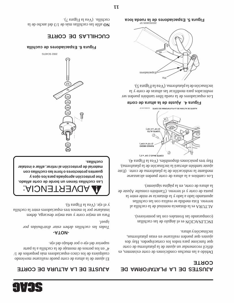
11
Los espaciadores de la rueda libre también pueden serreubicados para modificar las alturas de corte y lainclinación de la plataforma. (Vea la Figura 5).
Figura 5. Espaciadores de la rueda loca
AJUSTE DE LA ALTURA DE CORTE
El ajuste de la altura de corte puede realizarse moviendocualquiera de los cinco espaciadores más pequeños de 1/4" en los pernos de montaje de la cuchilla a la partesuperior del eje o por debajo del eje.
-NOTA-Todas las cuchillas deben estar distribuidas porigual.
Para un mejor corte y una mejor descarga, debeninstalarse por lo menos tres espaciadores entre la cuchillay el eje. (Vea la Figura 6).
CUCHILLAS DE CORTE
NO afile las cuchillas más de 1/3 del ancho de lacuchilla. (Vea la Figura 7).
Figura 6. Espaciadores de cuchilla
2002 SC407G
Las cuchillas tienen un borde de corte afilado.Use protección apropiada para los ojos yguantes protectores o forre las cuchillas conmaterial de protección al retirar, afilar e instalarcuchillas.
AJUSTES DE LA PLATAFORMA DECORTE
Debido a las muchas condiciones de corte existentes, esdifícil recomendar un ajuste de la plataforma de corteque funcione para todos los cortacéspedes. Hay dosajustes que pueden realizarse en estas plataformas,inclinación y altura.
INCLINACIÓN es el ángulo de las cuchillas(comparando las frontales con las posteriores).
ALTURA es la distancia nominal de la cuchilla alterreno. Esta medida se realiza con las cuchillasapuntando lado a lado y la distancia se mide entre lapunta de corte y el terreno. (También consulte Ajuste dela altura de corte, en la página siguiente).
Los cambios a la altura de corte pueden alcanzarsemediante la reubicación de la plataforma de corte. (Esteajuste también afectará la inclinación de la plataforma).Hay tres posiciones disponibles. (Vea la Figura 4).
Figura 4. Ajuste de la altura de corte
ADVERTENCIA:
Pin
Espaciadores
2003SGB005 SP
SC405G-06 SP
CORTE BAJO (1 3/4" a 3")
CORTE ALTO (3 1/4" a 4 1/2")
RANGO MEDIO(2 1/2"a 3 3/4")
AJUSTE DE ALTURA DE LA PLATAFORMA DE CORTE

10
-NOTA-La correa de transmisión hidráulica es cargadapor resortes y no necesita ajuste.
Para ajustar la transmisión de la plataforma de corte ylas correas de las cuchillas:
1.Retire la cubierta de la correa.
TENSIÓN DE LA CORREA
Correa
Perno "J"
ArandelaTuerca
Plataforma
Figura 3. Ajuste de la correa de la plataforma decorte a mano derecha
Detenga el motor y quite la llave del encendidoantes de realizar cualquier ajuste. Espere que todaslas partes móviles se detengan antes de comenzara trabajar.
9.PARA DETENERSE, apriete ambas palancas,bloquee los seguros de neutral y ponga la palanca deajuste de velocidad en posición neutral.
10.Para mover la máquina en reversa, apriete ambaspalancas de control de dirección.
11.Para “rodar libremente” o mover la máquina con elmotor apagado, gire contra el sentido del reloj laspalancas de la válvula de descarga ubicadas en laparte posterior de las bombas, a las posiciones de“rodar libremente”. Para operar la máquina, laspalancas de la válvula de descarga deben girarse enel sentido del reloj hasta las posiciones de cerrado. (Vea la Figura 1).
Figura 1. Válvulas de descarga
Figura 2. Ajuste de la correa de transmisión de la platforma
2.Ajuste la correa de transmisión de la plataforma decorte con un calibrador de tensión. Ajuste la correade modo que la misma se mueva 1/2" con 10 librasde presión. Ajuste la tensión apretando o aflojando latuerca del perno tipo J. (Vea la Figura 2).
-NOTA-Debido al estiramiento inicial de la correa, y paraevitar que la correa patine, verifique este ajustedespués de las primeras 2, 4, y 8 horas de operación.
3.Ajuste la correa de transmisión de la cuchilla a manoderecha con un calibrador de tensión. Ajuste lacorrea de modo que la misma se mueva 1/2" con 10libras de presión. Ajuste la tensión apretando oaflojando la tuerca del perno tipo J. (Vea la Figura3).
4.Vuelva a colocar la cubierta de la correa.
PRECAUCIÓN:
SWZ05DMPVLV SP Palancas de válvula de descarga(posición cerrada)
TUERCAPERNO"J"CORREA
EXTREMO DE SOPORTE EN L
ARANDELA
SC400G SP
TENSIÓN DE LA CORREA DE TRANSMISIÓN DE LAPLATAFORMA DE CORTE
POLEA DE ALINEACIÓN - LADO IZQUIERDO

9
OPERACIÓN DEL CORTACÉSPED(CONTINUACIÓN)
2.Antes de arrancar el motor:
*Verifique el nivel de aceite en el motor y en eldepósito hidráulico
*Llene el tanque de combustible con gasolinalimpia, reciente y sin plomo.
*Abra la válvula de combustible que está al fondodel tanque.
-NOTA-
Use gasolina con un octanaje no menor de 87 yun máximo de 10% de Etanol.
NO use combustible E85. El uso del combustible E85dañará severamente el motor.
* La palanca de ajuste de velocidad debe estar enposición NEUTRAL.
* El interruptor de embrague de las cuchillas debe estaren la posición OFF.
* Los seguros de neutral deben estar en la posiciónneutral de bloqueo.
* Las palancas de presencia del operador deben estarliberadas.
* El interruptor de encendido debe estar en ON.
* El freno de estacionamiento debe estar en ON.
3.Arranque el motor:
* Estrangule según sea necesario. Si el motor estáfrío, tire de la perilla de estrangulación. Cuando elmotor arranque, lentamente empuje elestrangulador. Si el motor se ahoga, repita laoperación de arriba. Cuando el motor está tibio,puede no ser necesario el uso delestrangulador.
4.Accione las cuchillas de corte presionando laspalancas de operador y tirando el interruptor delembrague de la cuchilla hacia la posición ON.Presione el interruptor a la posición OFF paradesconectar las cuchillas de corte.
* Arranque en frío. En la primavera y el otoño,cuando las temperaturas en la mañana son frías,puede ser difícil arrancar la máquina debido a lacarga paraestática de la transmisión hidráulica.Para liberar esta carga, tire hacia afuera y haciaarriba la cadena de.
desembrague ubicada en el lado derecho de la máquinadetrás de la llanta. Esto permitirá que arranque elmotor fácilmente. Cuando el motor está caliente, liberelentamente la cadena de desembrague para conectar elsistema hidráulico.
Si no está familiarizado con la operación de latransmisión hidrostática y la característica de girocero, practique girando y maniobrando con loscontroles manuales antes de accionar las cuchillasde corte.
5.Accione las cuchillas de corte tirando del interruptorde embrague de la cuchilla a la posición ON.Presione el interruptor a la posición OFF paradesconectar las cuchillas de corte.
-NOTA-Cuando el PTO está accionado o (posiblemente)desconectado, es normal escuchar un chirrido desdela parte inferior de la máquina. Es causado por elengrane de los platos del embrague eléctricosmientras el cortacésped adquiere velocidad. Paraalcanzar una mayor vida del equipo, accione elembrague con el motor a 3/4 de aceleración, no bajocarga completa.
7.Mientras está apretando las palancas del freno dedirección con ambas manos, libere ambos seguros dela posición neutral.
-NOTA-¡Sólo se recomienda la velocidad máxima paratransporte!
6.Libere el freno de estacionamiento. Mueva lapalanca de ajuste de velocidad hasta la velocidad decorte deseada.
8. Cuando las palancas del freno de dirección se liberan, la máquina se desplazará en línea recta. Para realizar un giro a la derecha, apriete la palanca derecha. Para girar a la izquierda, apriete la palanca izquierda.
ADVERTENCIA:
390S0138 SP
TIRE HACIA ARRIBA PARA ACCIONAR
PRESIONE HACIA ABAJO PARADESCONECTAR

8
MANTENIMIENTO Y ALMACENAMIENTO(CONTINUACIÓN)
PROCEDIMIENTOS DE ARRANQUE INICIAL(PRIMER DÍA DE USO OAPROXIMADAMENTE 10 HORAS)
17.Desconecte la batería o retire el cable de la bujíaantes de hacer cualquier reparación. Desconecteprimero el terminal negativo y el terminal positivodespués. Al terminar la reparación, vuelva aconectar el terminal positivo primero y el negativodespués.
5.Si el cortacésped debe ser inclinado para practicarlemantenimiento o ajuste, retire la batería y drene lagasolina del tanque de combustible y el aceite delcárter.
6.Mantenga apretados todos los pernos, tuercas, ytornillos, para asegurar que la máquina esté encondiciones seguras de trabajo. Verifiquefrecuentemente los pernos de montaje de la cuchillapara asegurarse que estén ajustados. Reemplacetodas las calcomanías desgastadas o dañadas.
7.Retire la grasa y los desechos de las unidades de corte,de la transmisión, del silenciador y del motor paraprevenir incendios. Limpie cualquier derrame de aceiteo combustible.
8.El motor debe estar apagado antes de revisar el nivelde aceite o de agregarlo al cárter.
9.Permita que el motor se enfríe antes de almacenarlo.
10.NO almacene la máquina cerca de un fuego abierto.
11.Corte el combustible durante el almacenamiento o eltransporte.
12.Siempre almacene la gasolina en un recipiente rojo,aprobado para seguridad.
13.Use soportes de gato para apoyar componentescuando sea necesario.
14.Libere cuidadosamente la presión de loscomponentes que tengan energía almacenada.
15.Tenga cuidado al revisar las cuchillas. Forre lascuchillas o use guantes y tenga cuidado al darservicio a las cuchillas. Sólo reemplace o afile lascuchillas. NUNCA enderece ni suelde las cuchillas.
16.Tenga cuidado cuando dé servicio a la batería, yaque contiene ácido, el cual es corrosivo y podríacausar quemaduras a la piel y a la ropa.
Las baterías plomo-ácido producen gasesinflamables y explosivos. Para evitar lesionespersonales al revisar, probar o cargar baterías, NOUSE materiales que produzcan humo cerca de lasbaterías. Mantenga los arcos, las chispas y lasllamas lejos de las baterías. Proporcioneventilación apropiada y use gafas de seguridad.
ADVERTENCIA:
Los postes de la batería, los terminales y losaccesorios relacionados contienen plomo ycompuestos de plomo; el Estado de Californiaidentifica a estas sustancias químicas comocausantes de cáncer y daño a los órganosreproductivos. Lávese las manos después demanipular baterías.
ADVERTENCIA:
1.Verifique la correcta tensión de las correas a las 2, 4y 8 horas. Ajuste como lo considere necesario.
2.Verifique el ajuste neutral de las varillas de control dedirección (Consulte la sección Ajustes, página 13).
3.Verifique la presión adecuada de las llantas.Ruedas locasLlantas macizasRuedas motrices12 PSI
4.Revise que no haya tornillería floja. Apriete segúnsea necesario.
5.Verifique el ajuste adecuado de los interruptores deseguridad:
*En máquinas de arranque eléctrico, el motor debehacer girar el cigüeñal y arrancar si la máquina estáen neutro, el interruptor PTO de accionamientoapagado (OFF) y el freno de estacionamientoaccionado (ON).
6.Aplique lubricante a todas las conexiones.El lubricante se aplicó en fábrica. Esto sólo es unarevisión preventiva para asegurarse de que todas lasconexiones hayan sido lubricadas.
OPERACIÓN DEL CORTACÉSPED
1.Lea y entienda las instrucciones de seguridad antes
de tratar de operar esta máquina.
7
CONSIDERACIONES DE OPERACIÓN(CONTINUACIÓN)
7.Desconecte la potencia a la plataforma de corteantes de retroceder. No corte en reversa a menosque sea absolutamente necesario y sólo después deobservar toda el área detrás del cortacésped. Si debecortar en reversa, mantenga la vista constantementehacia la parte posterior de la máquina y cortelentamente.
8.Desconecte la potencia a la plataforma de corte antesde cruzar carreteras, caminos o caminos de grava.Detenga las cuchillas si no está cortando el césped.
9.Apague el motor y espere hasta que las cuchillas sedetengan completamente antes de retirar elrecipiente del recogedor de césped.
10.Nunca levante la plataforma de corte mientras lascuchillas estén girando.
11.Mantenga las manos y pies lejos de las cuchillas decorte y las partes móviles. El contacto puede causardaños.
12.NO opere sin la tolva de descarga lateral instalada yen la posición baja.
13.NO dirija la descarga del material hacia otras personas,ni permita que haya nadie cerca a la máquina mientrasestá en funcionamiento.
14.Si las cuchillas de corte golpean un objeto sólido o siel equipo comienza a vibrar en forma anormal,detenga el motor, desconecte los cables de bujía, ybusque inmediatamente la causa. Generalmente, lavibración es una advertencia de alguna falla. Busquesi hay daños o piezas defectuosas en la máquina.Repare cualquier daño antes de arrancar el motor ode operar la plataforma de corte. Asegúrese de quelas cuchillas estén en buen estado y que sus pernosestén ajustados.
15.Tome toda precaución posible cuando deje lamáquina sin atención, como desconectar elcortacésped, detener el motor y quitar la llave.
NO toque el motor ni el silenciadormientras el motor está funcionando, niinmediatamente después de detenerlo.Estas zonas pueden estar losuficientemente calientes como paracausar una quemadura.
PRECAUCIÓN:
16.NO opere el equipo bajo la influencia de alcohol odrogas.
17.Tenga cuidado al cargar o descargar la máquina en unremolque o un camión.
18.Tenga cuidado al aproximarse a esquinas ciegas,arbustos, árboles, u otros objetos que puedan disminuirla visibilidad.
19.No cambie los ajustes del controlador del motor niopere a mayor velocidad de la nominal. Vea elmanual del operador del motor para obtenerinformación sobre los ajustes del motor.
20.Nunca deje la máquina funcionando sin atención.
MANTENIMIENTO YALMACENAMIENTO
1.Sólo permita que personal entrenado dé servicio a lamáquina.
2.Estacione la máquina en terreno plano.
3.Nunca realice ajustes a la máquina con el motor enoperación a menos que se le indique específicamentehacerlo así. Si el motor está funcionando, mantengalas manos, los pies, y la ropa lejos de las piezas móviles.
4.Desconecte la transmisión, baje los implementos,detenga el motor y quite la llave o desconecte los cablesde bujía para evitar un arranque accidental del motorcuando esté dando servicio o ajuste a la máquina.Espere que todo movimiento cese antes de realizarcualquier ajuste, limpieza o reparación.
¡NUNCA PONGA LAS MANOS EN LA TOLVA DEDESCARGA POR NINGÚN MOTIVO!
CUCHILLAS GIRATORIASPELIGRO:
PELIGRO: NO opere el motor dentro de un edificio ni enun área encerrada sin ventilación apropiada.Los gases de escape son peligrosos ycontienen monóxido de carbono que puedencausar daño cerebral y la muerte.

6
CONSIDERACIONES PREVIAS A LAOPERACIÓN (CONTINUACIÓN)
B.Preste atención a agujeros, piedras, raíces yotros peligros ocultos en el terreno. Manténgasealejado de toda pendiente vertical. Tengacuidado con las obstrucciones presentes arribade su cabeza (ramas bajas, etc.), obstáculossubterráneos (aspersores, tubos, raíces deárboles, etc.) Ingrese con precaución a un áreanueva. Preste atención a posibles peligrosocultos.
9.Siempre debe estar instalada la tolva de descarga y enla posición baja en la plataforma de corte de la descargalateral, excepto cuando el recogedor de césped opcionalo la placa de mezcla de paja Scag estén correctamenteinstalados.
10.Si la descarga del cortacésped se tapona, apague elmotor, quite la llave de encendido y espere que cesetodo movimiento antes de quitar la obstrucción.
NO use la mano para desatascar la tolva dedescarga. Use una varilla u otro dispositivopara retirar el material atascado después deapagar el motor y que las cuchillas paren degirar.
ADVERTENCIA:
11.Verifique a intervalos frecuentes que los pernos demontaje de la cuchilla estén correctamente ajustados.
12.Asegúrese de que todas las conexiones hidráulicasestén apretadas y que todas las mangueras hidráulicasy las líneas estén en buen estado antes de arrancar lamáquina.
CONSIDERACIONES DEOPERACIÓN1.Antes de operar el cortacésped, debe familiarizarse
con todos los controles del cortacésped y el motor.Es importante conocer la ubicación, función yoperación de estos controles para la operación seguray eficiente del cortacésped.
2. Arranque el motor cuando los seguros de neutralestán en la posición neutral de bloqueo, las hojas decorte desconectadas, el freno de estacionamientoaccionado y la palanca de ajuste de velocidad en laposición neutral.
3.Asegúrese que los conmutadores de bloqueofuncionen correctamente.
4.NO corte cuando niños y/o otras personas esténpresentes. Mantenga a los niños fuera del área decorte y al cuidado atento de un adulto responsabledistinto del operador. Esté atento y apague la máquinasi un niño ingresa al área.
5.NO LLEVE pasajeros.
NO OPERE en pendientes empinadas. Para probarsi puede trabajar en una cuesta, trate de retroceder(con la plataforma de corte baja). Si la máquinano puede retroceder en una pendiente sin que lasruedas resbalen, no la opere en dicha pendiente.
SIEMPRE desplácese a través de la pendientecuando sea posible. Nunca suba y baje lapendiente.
Reduzca la velocidad y tenga cuidado al girar o aloperar en pendientes, o en superficies húmedaso resbaladizas. Permita una distancia adicionalpara detenerse.
Opere la máquina suavemente, sin girosrepentinos, ni arranques o paradas en unapendiente.
SIEMPRE mantenga el equilibrio. Mantengafirmemente las asas y camine—no corra.
NO corte cerca de pendientes verticales, zanjasni terraplenes. La máquina podría volcarserepentinamente si una rueda pasa encima de unborde o si el borde se derrumba.
NO permita que personal sin entrenamiento operela máquina.
SIEMPRE CUMPLA CON LAS OPERACIONESAPROBADAS POR OSHA
ADVERTENCIA:
6.El uso de la máquina requiere atención. Paraevitar la pérdida de control:
A.Corte el césped sólo con luz de día o buena luzartificial.
5
CONSIDERACIONES PREVIAS A LA OPERACIÓN(CONTINUACIÓN)
B.Use solamente un recipiente aprobado paragasolina.
C. NO agregue combustible a un motor enoperación ni a un motor caliente. Permita queel motor se enfríe por varios minutos antes deagregar el combustible.
D. Nunca abastezca de combustible alcortacésped bajo techo ni en un remolquecerrado.
E. Nunca almacene el cortacésped o elrecipiente de combustible donde haya unallama abierta, chispa o luz piloto, como de uncalentador de agua u otros aparatos.
F. Nunca llene recipientes dentro de un vehículoni en un camión o remolque que tenga forrode material plástico. Siempre coloque losrecipientes en el terreno lejos de su vehículoantes de abastecerlos de combustible.
G. Retire la máquina del camión o del remolquey abastézcala de combustible en el terreno. Siesto no es posible, añada el combustible conun recipiente portátil en lugar de usar unaboquilla de un dispensador de gasolina.
H. Mantenga la boquilla en contacto con elborde del tanque de combustible o con laabertura del recipiente hasta terminar dellenar el combustible. No utilice undispositivo que bloquee la boquilla enposición abierta.
I. Si derrama combustible en la ropa,cámbiesela inmediatamente.
J. Coloque nuevamente la tapa de gasolina yapriete firmemente.
5.Siempre use ropa apropiada. La ropa holgada, elcabello largo o las joyas podrían enredarse en partesmóviles. No opere la máquina llevando pantalonescortos; siempre lleve ropa de protección adecuada,incluyendo pantalones largos. Es recomendable llevargafas de seguridad, zapatos de seguridad y un casco,pues es requerido por algunos reglamentos locales ynormas del seguro.
6.Mantenga la máquina y los accesorios en buenascondiciones de operación. Mantenga todas las guardasy dispositivos de seguridad en su lugar. Si una guarda,un dispositivo de seguridad o una calcomanía, estándefectuosos o dañados, repárelos o reemplácelos antesde operar la máquina.
7.Llene el tanque de combustible con gasolina limpia yreciente con un octanaje mínimo de 87 y hasta unmáximo de 10% de Etanol. Para evitar lesionespersonales o daños a la propiedad, tenga muchocuidado al manipular gasolina. La gasolina esextremadamente inflamable y los vapores sonexplosivos.
NO use combustible E85. El uso del combustible E85dañará severamente el motor.
Siempre use protectores auditivos. El operaresta máquina por períodos prolongados detiempo puede causar pérdida de la audición.
ADVERTENCIA:
A. Mantenga los objetos inflamables (cigarrillos,fósforos o cerillos, etc.), las llamas abiertas ychispas, lejos del tanque y el recipiente decombustible.
Esta máquina está equipada con un sistema debloqueo diseñado para evitar lesiones personalesal operador y a terceros. Esto se logra evitando queel motor arranque a menos que la transmisión deplataforma esté desconectada, el freno deestacionamiento accionado y la palanca de ajustede velocidad en la posición neutral. El sistemaapaga el motor si el operador libera las palancasde presencia del operador con la transmisión deplataforma accionada y/o la palanca de ajuste develocidad en una posición diferente de la neutral yel freno de estacionamiento no accionado. Nuncaopere el equipo con el sistema de bloqueodesconectado ni funcionando defectuosamente.
ADVERTENCIA:
NO OPERE SIN EL EQUIPO MEZCLADOR DE PAJA DE LA TOLVA DEDESCARGA, O SIN EL RECOGEDOR DE CÉSPED INSTALADOS.
ADVERTENCIA
8.Antes de intentar arrancar el motor, mueva lapalanca de ajuste de velocidad a la posición neutral,mueva el interruptor de accionamiento de la cuchilla ala posición OFF, aplique el freno de estacionamientoy mueva los seguros de neutral a neutro.

4
INFORMACIÓN DE SEGURIDADINFORMACIÓN GENERAL DE SEGURIDADSu cortacésped es tan seguro como el operador. El error odescuido del operador puede ocasionar lesiones personalesgraves o la muerte. El control de riesgos y la prevención deaccidentes dependen del conocimiento, el interés, laprudencia, y el entrenamiento apropiado del personalrelacionado con la operación, el transporte, mantenimientoy almacenamiento del equipo. Cerciórese de que cadaoperador esté entrenado apropiadamente y completamentefamiliarizado con todos los controles antes de operar elcortacésped. El propietario/usuario puede evitar y esresponsable de los accidentes o heridas que les ocurran aellos mismos, a otras personas o a la propiedad.
LEA ESTE MANUAL DEL OPERADOR ANTES DETRATAR DE ARRANCAR SU CORTACÉSPED.
Si el operador o mecánico no puede leer inglés o español,es responsabilidad del propietario explicarles este material.
Hay disponible un manual de reemplazo en su distribuidorautorizado Scag o contactándose con Scag PowerEquipment, Service Department en P.O. Box 152, Mayville,WI 53050, o visitando su sitio web en www. scag.com.Puede descargar el manual para su máquina utilizando elmodelo y el número de serie o mediante el formulario decontacto para hacer su pedido. Indique el modelo y el númerode serie completos de su producto de Scag cuando solicitemanuales de reemplazo.
PALABRAS DE SEÑALIZACIÓN
Este símbolo significa “¡Atención! ¡Alerta! ¡Hay unriesgo para su seguridad!” El símbolo se usa con lassiguientes palabras de señalización para llamar su atenciónsobre mensajes de seguridad localizados en las calcomaníasdel equipo y a través de este manual. El mensaje que sigueal símbolo contiene información importante sobre seguridad.¡Para evitar posibles lesiones o la muerte, leadetalladamente el mensaje! Cerciórese de entendercompletamente las causas que pueden ocasionar lesioneso la muerte.
Palabra de señalización:
La palabra de señalización es distintiva y se encuentra enlas calcomanías de seguridad del equipo y a través de estemanual para alertar sobre la existencia y el grado de unacondición de peligro.
La palabra de señalización “DANGER” (PELIGRO) indicaque existe una situación extremadamente peligrosa en ocerca de la máquina, que tiene altas probabilidades deocasionar la muerte o una lesión irreparable si no se tomanlas precauciones apropiadas.
La palabra de señalización “WARNING”(ADVERTENCIA) indica que existe un riesgo en o cercade la máquina que puede ocasionar lesiones o la muerte sino se toman las precauciones debidas.
La palabra de señalización “CAUTION”(PRECAUCIÓN) es un recordatorio de que se debenseguir prácticas seguras en o cerca de la máquina y quede no seguirse, se pueden ocasionar lesiones personales.
Su seguridad y la de los demás dependen en gran parte deque usted conozca y comprenda todos los procedimientosy las prácticas de operación correcta de esta máquina.
CONSIDERACIONES PREVIAS A LAOPERACIÓN
1.Familiarícese con la operación segura del equipo, loscontroles del operador y las señales de seguridad.
2.NUNCA permita que niños o personas no calificadasoperen o den servicio a esta máquina.
3.NO PERMITA que los niños se suban o jueguen enla máquina, no es un juguete.
4.Retire del área que debe ser cortada todos los objetosque pudieran ser recogidos y arrojados por las cuchillas.
PELIGRO:
ADVERTENCIA:
PRECAUCIÓN:
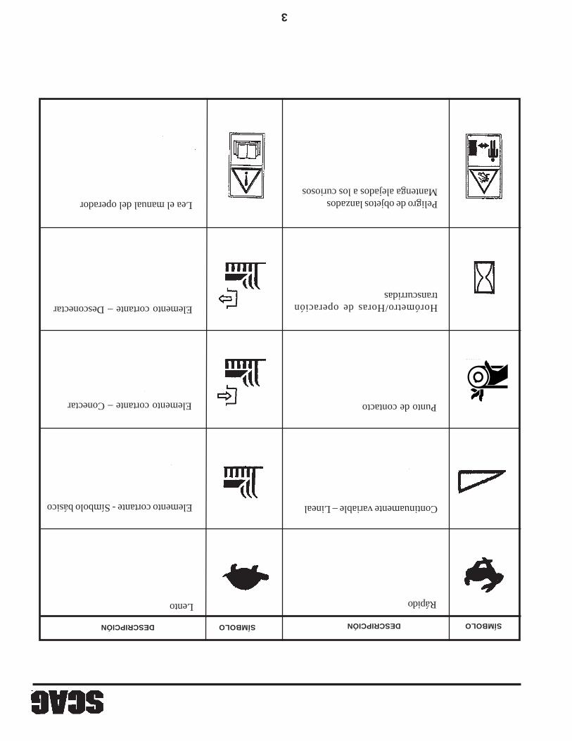
3
Lento Rápido
Elemento cortante – Conectar
Elemento cortante - Símbolo básico
Elemento cortante – Desconectar
Continuamente variable – Lineal
Lea el manual del operador Peligro de objetos lanzadosMantenga alejados a los curiosos
Punto de contacto
481039S
Horómetro/Horas de operacióntranscurridas
SÍMBOLODESCRIPCIÓN SÍMBOLODESCRIPCIÓN

2
Transmisión Ahogador
Encendido/ArranqueTensión del resorte en la polea
Aceite Apagado/Parada
SÍMBOLODESCRIPCIÓN SÍMBOLODESCRIPCIÓN
Símbolos ISO
Cuchilla giratoria
48071S
Freno de estacionamiento
Riesgo de caídaObjetos lanzados

1
INFORMACIÓN GENERALSÓLO USE DISPOSITIVOS APROBADOS PORSCAG.
Los accesorios y aditamentos fabricados por compañíasque no sean la propia Scag Power Equipment no estánaprobados para usarlos en esta máquina. El uso dedispositivos no aprobados, (especialmente los dispositivosde conducción “verticales”) puede ser peligroso.
ACCESORIOS Y ADITAMENTOSAPROBADOS POR SCAG:
GC-F4 (n/p 9055)GC-4D (n/p 9054)Placa desmenuzadora (n/p 9258, 9286, 9287)Sistema mezclador de paja Hurricane(n/p 9263, 9283, 9284)Sujetavasos (n/p 9240)Horómetro (n/p 48023)Deflector turbo (n/p 424208, 424209)Blade Buddy (n/p 9212)
SERVICIO AL MOTOR Y A LOSCOMPONENTES DEL TREN DE TRANSMISIÓN
Los detalles sobre servicio y reparación del motor y lasbombas hidráulicas no están cubiertos en este manual;sólo se proporcionan instrucciones de mantenimiento derutina y de servicio general. Para dar servicio a estoscomponentes durante el período de garantía limitada, esimportante contactar con su distribuidor Scag o encontrara un agente local de servicio autorizado del fabricante delcomponente. Cualquier trabajo no autorizado realizado enestos componentes durante el período de garantía puedeanularla.
REFERENCIA DE INSTRUCCIONES
Los lados “derecho” e “izquierdo”, “frontal” y “posterior”de la máquina se refieren a la izquierda y derecha deloperador cuando se encuentra en posición de operaciónnormal y de cara a la dirección de desplazamiento haciaadelante.
INTRODUCCIÓN
Su cortacésped se fabricó según las normas másexigentes de la industria. Sin embargo, la duración de lavida útil y el logro de la máxima eficiencia de sucortacésped dependen de que se sigan las instruccionesde operación, mantenimiento y ajuste indicadas en estemanual.
Si requiere información o servicio adicionales, contactecon su distribuidor de Scag Power Equipment.
Le sugerimos que se ponga en contacto con sudistribuidor cuando necesite reparaciones. Todos losdistribuidores Scag están informados de los últimosmétodos para dar servicio a este equipo y paraproporcionar un servicio oportuno y eficiente en el sitiode trabajo o en el taller de servicio. Ellos cuentan con lalínea completa de piezas de repuesto Scag.
EL REEMPLAZO DE CUALQUIER PARTE DEESTE PRODUCTO POR OTRA PIEZA DEREPUESTO QUE NO ESTÉ AUTORIZADA POREL FABRICANTE PUEDE PERJUDICAR ELRENDIMIENTO, DURABILIDAD OSEGURIDAD DE ESTE PRODUCTO.
EL USO DE PIEZAS DE REPUESTO QUE NOSEAN SCAG ORIGINALES ANULARÁ LAGARANTÍA.
Para una mejor visualización, algunas ilustraciones y lasfiguras en este manual pueden mostrar las protecciones,las guardas o los platos, abiertos o retirados. Bajoninguna circunstancia su cortacésped debe operarse sinestos accesorios colocados en su lugar.
Toda la información está basada sobre lainformación disponible del producto al momento deaprobarse la impresión. Scag Power Equipment sereserva el derecho de realizar cambios en cualquiermomento sin previo aviso y sin contraer ningunaobligación.
TM
RIESGO DE CAÍDASÓLO USE DISPOSITIVOS DE
CONDUCCIÓN APROBADOS POR SCAGLEA EL MANUAL DEL OPERADOR481109 SP
ADVERTENCIA

TABLA DE CONTENIDO(CONTINUACIÓN)
TEMA PÁGINA
Cambio del elemento del filtro de aceite hidráulico.....................................16Mantenimiento del aceite del motor.............................................................17Mantenimiento del filtro de aire del motor....................................................17Verificación del nivel de electrolito y limpieza de batería............................17Carga de la batería......................................................................................18Arranque por puente....................................................................................18Limpieza de la máquina..............................................................................18Identificación de fallas en las condiciones de corte.....................................19-21Especificaciones técnicas...........................................................................22-23
II
Notas..........................................................................................................24Conjunto de la rueda libre.............................................................................25SWM-36".....................................................................................................26-27Plataforma de corte SWM-48", 52", 61".......................................................28-29Plataforma del motor - Arranque manual.....................................................30-31Plataforma del motor - Arranque eléctrico (SWZ-21KAE)............................32-33Componentes de transmisión y freno..........................................................34-35Conjunto del mango - Bastidor pequeño (16").............................................36-37Conjunto del mango - Bastidor grande (20")...............................................38-39Conjunto hidráulico.....................................................................................40-41Conjunto de bomba hidráulica.....................................................................42-43Mazo de cables de la plataforma del motor (arranque manual)...................44Mazo de cables del mango (arranque manual)...........................................44Mazo de cables de la plataforma del motor - Arranque eléctrico(SWZ-21KAE)..............................................................................................45Mazo de cables del mango - Arranque eléctrico (SWZ-21KAE)....................45Adaptador del mazo de cables-Kawasaki (16 HP, 17 HP y 19 HP).............46Calcomanías de repuesto............................................................................47-49Notas..........................................................................................................50Declaración de garantía ...................................... Dentro de la cubierta posterior
Lista de partes ilustrada

TABLA DE CONTENIDO
TEMA PÁGINA
Introducción.................................................................................................1Referencia de instrucciones........................................................................1Servicio al motor y a los componentes del tren de transmisión...................1Símbolos.....................................................................................................2-3Instrucciones generales de seguridad.........................................................4Palabras de señalización............................................................................4Consideraciones previas a la operación.....................................................4-6Consideraciones de operación....................................................................6-7Mantenimiento y Almacenamiento..............................................................7-8Procedimientos de arranque inicial.............................................................8Operación del cortacésped.........................................................................8-9Tensión de la correa....................................................................................10Ajustes de la plataforma de corte................................................................11Ajuste de la altura de corte..........................................................................11Cuchillas de corte........................................................................................11Ajuste del deflector de corte personalizado.................................................12Ajuste neutral...............................................................................................13Ajuste de la varilla de control de dirección..................................................13Ajuste de alineación....................................................................................14Freno de estacionamiento...........................................................................14Tabla de Lubricación y Mantenimiento........................................................15Verificar el nivel de aceite hidráulico...........................................................16Cambio de aceite hidráulico........................................................................16
I
WE SUPPORT OPE
TECHNICIANCERTIFICATION

EL INCUMPLIMIENTO DE LAS PRÁCTICAS SEGURAS DEOPERACIÓN PUEDE RESULTAR EN LESIONES GRAVES.*Mantenga todas las guardas en su posición, especialmente la de la
tolva de descarga de césped.*Antes de realizar cualquier mantenimiento o servicio, detenga la
máquina y quite el cable de la bujía y la llave de encendido.*Si un mecanismo se atasca, detenga el motor antes de limpiar.*Mantenga las manos, los pies y la ropa lejos de las partes móviles.*Lea este manual completamente así como cualquier otro manual
proporcionado con su cortacésped.*Mantenga a otras personas alejadas del tractor (sólo una persona debe
usarlo a la vez).*NO OPERE en pendientes empinadas. Para probar si puede trabajar
en una cuesta, trate de retroceder (con la plataforma de corte baja).Si la máquina puede retroceder por la pendiente sin que las ruedas seresbalen, reduzca la velocidad y opere con extremo cuidado.SIEMPRE CUMPLA CON LAS OPERACIONES APROBADAS POR
OSHA.*NO corte en césped mojado. El césped mojado reduce la tracción y el
control de dirección.
Este manual cubre las instrucciones de operacióny la lista de partes ilustradas para:
Cuando se refiera a este producto siempre use el número de seriecompleto que aparece en la etiqueta de número de serie.
SWZ36A-16KAIcon número de serie de D4500001 a D4599999SWZ48V-17KAIcon número de serie de D4600001 a D4699999SWZ52V-17KAIcon número de serie de D4700001 a D4799999SWZ52V-19KAIcon número de serie de D4800001 a D4899999SWZ-19KAIcon número de serie de D5100001 a D5199999SWZ-21KAEcon número de serie de D5200001 a D5299999SWM-52Vcon número de serie de D5400001 a D5499999SWM-61Vcon número de serie de D5500001 a D5599999
RECUERDE - ¡SU CORTACÉSPED ES TAN SEGURO COMO ELOPERADOR!El control de riesgos y la prevención de accidentes dependen del conocimiento, elinterés, la prudencia, y el entrenamiento apropiado del personal relacionado con laoperación, el transporte, mantenimiento y almacenamiento del equipo.
ADVERTENCIA:

MODELO SWZ
MA
NU
AL
DE
L O
PE
RA
DO
R
ESTE MANUAL CONTIENE LASINSTRUCCIONES DE OPERACIÓN Y LAINFORMACIÓN DE SEGURIDAD PARA SUCORTACÉSPED SCAG. LA LECTURA DE ESTEMANUAL LE PUEDE AYUDAR EN ELMANTENIMIENTO Y LOS PROCEDIMIENTOSDE AJUSTE A FIN DE MANTENER SUCORTACÉSPED TRABAJANDO A LA MÁXIMAEFICIENCIA. LOS MODELOS ESPECÍFICOSCUBIERTOS POR ESTE MANUAL ESTÁNINDICADOS EN LA CUBIERTA INTERIOR.ANTES DE OPERAR SU MÁQUINA, LEA TODALA INFORMACIÓN INCLUIDA.
© 2007SCAG POWER EQUIPMENTDIVISION OF METALCRAFT OF MAYVILLE, INC.
PARTE Nº 03226IMPRESO EN
ABRIL DE 2007IMPRESO EN
EE.UU.