sx 2003 owner’s manual manuale d’uso manuel · pdf file65 art.nr. 3.210.47 04/2002...
TRANSCRIPT

Art
.Nr.
3.21
0.47
04/2
002
65
SX
OW
NER
’S M
AN
UA
L M
AN
UA
LE D
’USO
MA
NU
EL D
’UTI
LISA
TIO
NM
AN
UA
L D
E IN
STR
UC
CIO
NES
2003
BED
IEN
UN
GSA
NLE
ITU
NG

EN
GLIS
H
1
Please insert the serial numbers of your motorcycle in the boxes below
PLEASE INSERT BELOW THE SERIES NUMBERS OF THE MOTORCYCLE
FRAME NUMBER
ENGINE NUMBER
STAMPOF DEA-
LER
IMPORTANT
PLEASE READ THIS MANUAL THOROUGHLY BEFORE LETTING YOURYOUNGSTER RIDE THE MOTORCYCLE FOR THE FIRST TIME. THIS MANUALCONTAINS IMPORTANT INFORMATION AND RECOMMENDATIONS THATWILL HELP YOU AND YOUR YOUNGSTER TO OPERATE AND HANDLE THEMOTORCYCLE PROPERLY.
IN THE INTEREST OF EVERYBODY INVOLVED, WE URGE YOU TO PAY PARTI-CULAR ATTENTION TO INSTRUCTIONS AND INFORMATION MARKED ASFOLLOWS:
� WARNING �IGNORING THESE INSTRUCTIONS CAN BE DANGEROUS TO LIFEAND LIMB.
! CAUTION !IGNORING THESE INSTRUCTIONS MAY DAMAGE PARTS OF THEMOTORCYCLE OR IMPAIR THE MOTORCYCLE’S TRAFFICSAFETY.
Chassis number
Engine number
Stamp of dealer
KTM SPORTMOTORCYCLE AG RESERVES THE RIGHT TO MODIFY ANY EQUIPMENT, TECHNICAL SPECIFICATIONS, COLORS,MATERIALS, SERVICES OFFERED AND RENDERED, AND THE LIKE SO AS TO ADAPT THEM TO LOCAL CONDITIONS WITHOUT
PRIOR NOTICE AND WITHOUT GIVING REASONS, OR TO CANCEL ANY OF THE ABOVE ITEMS WITHOUT SUBSTITUTING THEM
WITH OTHERS. IT SHALL BE ACCEPTABLE TO STOP MANUFACTURING A CERTAIN MODEL WITHOUT PREVIOUS ANNOUNCE-MENT. IN THE EVENT OF SUCH MODIFICATIONS, PLEASE ASK YOUR LOCAL KTM DEALER FOR INFORMATION.

EN
GLIS
H
2
Introduction
Now you own a modern motorcycle that you and your youngster will certainly enjoy,provided that you service and maintain it properly. This manual contains importantinformation on the operation and maintenance of your new KTM motorcycle. It wentto press describing your model’s latest state of development. Nevertheless, the descrip-tions may deviate slightly from the current design as our motorcycles are permanentlyimproved.The Owner's Manual is an integral part of the motorcycle and must be han-ded over to the new owner when the motorcycle is sold.
We expressly point out that work marked with an asterisk in the chapter "Maintenancework on the chassis and engine" must be performed by a KTM workshop. If mainten-ance work should become necessary during a competition, it must be performed by atrained mechanic.
Please strictly observe the prescribed running-in periods and inspection and maintenan-ce intervals. Compliance with these instructions will significantly prolong the life of yourmotorcycle.Be sure to have the maintenance work carried out by a KTM workshop to avoid losingyour right to claim under the warranty.
For the safety of your child, only use spare parts and accessories approved by KTM.KTM shall not assume any liability for other products or consequential damage resul-ting from the use of such products.
When special needs arise, please contact a KTM dealer, who will seek the assistance ofthe KTM importer if necessary.
PARENTS SHOULD KEEP IN MIND that the safety of their youngsters always dependson the efforts made by the parents to ensure that the motorcycle is kept in good wor-king order and only used on safe terrains. Nevertheless, driving the motorcycle, like dri-ving any other vehicle, involves a potential risk. Therefore, please make sure that all fun-damental precautions are taken. Please also read the „INFORMATION ON SAFE DRI-VING FOR PARENTS“ on page 4.
Riding an off-highway motorcycle is a wonderful form of outdoor recreation and wecertainly hope that you and your youngsters will enjoy it to the full. However, thisenjoyable outdoor activity can cause environmental problems or lead to conflicts withother people. Responsible use of the motorcycle will prevent such problems and con-flicts. You can contribute to securing the future of motorcycling by making sure that youand your youngsters only use the motorcycle within the limits established by the appli-cable laws, making environmental protection one of your top priorities and never viola-ting other people’s rights.
In this spirit, we hope that you and your youngsters will always safely enjoy yourmotorcycle!
KTM SPORTMOTORCYCLE AG5230 MATTIGHOFEN, AUSTRIA
Attachments: 1 spare parts manual chassis & engine
ALL RIGHTS RESERVED TO MAKE ALTERATIONS TO DESIGN AND MODEL.© by KTM SPORTMOTORCYCLE AG, AUSTRIA All rights reserved

EN
GLIS
H
3
IMPORTANT WARRANTY ANDGUARANTEE INFORMATIONE
KTM mini-sports motorcycles are designed and constructed to resist the usualwear and tear of normal use in competitions.The motorcycles comply with the regulations and categories currently in effectwith the leading international motorcycle associations.
Observance of the service, maintenance and tuning instructions for the engi-ne and chassis specified in the Owner's Manual is a prerequisite for faultlessoperation and the avoidance of premature wear. An improperly tuned chassiscan lead to damage and breakage of the chassis components (see chapter onchecking the basic chassis setting).
The service work specified in the "Lubrication and Maintenance Schedule"must be performed by a KTM workshop and recorded in the service manualotherwise claims under the warranty shall become void.
The fuels and lubricants specified in the Owner's Manual or automotive fluidswith equivalent specifications must be used in accordance with the mainten-ance schedule.
No claims can be filed under the warranty for damage or consequential dama-ge caused by manipulations or conversions to the motorcycle.
The use of the motorcycle under extreme conditions, e.g. on extremelymuddy and wet terrain, can lead to higher than average wear on componentssuch as the drive train or the brakes. In this case it may become necessary toservice or replace wear parts before the service limit specified in the mainten-ance schedule has been reached.
In accordance with the international quality managementISO 9001 standard, KTM uses quality assurance processesthat lead to the highest possible product quality.

EN
GLIS
H
4The 65 SX mini motorcycles are off-road motorcycles designed for one person only. They are not allowed onpublic roads.
The vehicle dimensions and components are designed for children from 6 to 10 years of age with a maximumweight of. 50 kg (22,65 lb) and a maximum height of 160 cm.(63,04 in)
– Have your youngster wear proper protective gear whenever he or she rides the motorcycle: helmet, eye protection, chest, back, arm and leg protectors, gloves and boots. To set a good example, be sure to wearprotective gear yourself whenever riding a motorcycle!
– Adjust the clutch lever and hand brake lever to match your child's hand size (with gloves).– Adjust the basic setting of the foot brake pedal to your child's seating position.– Before your youngster takes his or her first ride, explain how each of the controls works and check if your
youngster has understood what you explained. We recommend to review the entire owner’s manual withyour youngster item by item, paying particular attention to the specially marked warnings and pointing outthe danger of injury.
– Instruct your youngster about riding and falling techniques, explain how the motorcycle will respond to shifting of the rider’s weight, etc.
– Before starting the motorcycle for the first time check whether the basic fork and shock absorber settings aresuitable for your child's weight (see chapter on checking the basic chassis setting)
– Before using the motorcycle you should always check all components for proper operation (see maintenance schedule). Have your youngster perform these technical checks himself / herself as well.
– Whenever you go for a ride with your youngster, keep in mind that the speed should be adjusted to youryoungster and not the other way around.
– Your youngster must understand that all instructions he or she receives from you or any other supervisingadult must be followed.
– Your child must be physically ready to ride a motorcycle. This means that he or she must at least be able toride a bicycle. Being good at sports that require fast reactions is an additional advantage. Your youngstershould be strong enough to pick up the motorcycle after a fall.
– Never demand too much of your youngster. Give him or her time to get used to the motorcycle and toimprove his / her riding skills. Do not even consider letting your youngster participate in a race before his /her physical condition, riding skills and motivation have sufficiently developed.
– Explain to your youngster that he / she should always adjust his / her riding speed to the local conditions aswell as to his / her own riding skills and that excessive speed can cause falls and severe injuries. Always keepin mind that youngsters tend to underestimate dangers or fail to recognize them altogether. The riding speedmust be reduced, in particular, on unknown terrain.
– Never let your youngster ride the motorcycle without supervision. An adult should always be present.– The motorcycle is designed for one rider only. Your youngster is not allowed to transport a passenger.– When you go for a ride, somebody at home should always know where you are going and when you will
be back. This makes it easier to send you help, should problems occur.
IMPORTANT INFORMATION FOR PARENTS ABOUT SAFE DRIVING

EN
GLIS
H
5
TABLE OF CONTENTS
Page
SERIAL NUMBER LOCATIONS . . . . . . . . . . . . . . . . . . . . .6
Chassis number . . . . . . . . . . . . . . . . . . . . . . . . . . . . . .6
Engine number . . . . . . . . . . . . . . . . . . . . . . . . . . . . . .6
OPERATION INSTRUMENTS . . . . . . . . . . . . . . . . . . . . . .6
Clutch lever . . . . . . . . . . . . . . . . . . . . . . . . . . . . . . . .6
Hand brake lever . . . . . . . . . . . . . . . . . . . . . . . . . . . .6
Short circuit button . . . . . . . . . . . . . . . . . . . . . . . . . . .6
Filler cap . . . . . . . . . . . . . . . . . . . . . . . . . . . . . . . . . . .7
Fuel tap . . . . . . . . . . . . . . . . . . . . . . . . . . . . . . . . . . .7
Choke . . . . . . . . . . . . . . . . . . . . . . . . . . . . . . . . . . . .7
Shift lever . . . . . . . . . . . . . . . . . . . . . . . . . . . . . . . . . .7
Kickstarter . . . . . . . . . . . . . . . . . . . . . . . . . . . . . . . . .8
Foot brake pedal . . . . . . . . . . . . . . . . . . . . . . . . . . . . .8
Compression damping of shock absorber . . . . . . . . . . .8
Rebound damping function of the shock absorber . . . .8
Plugin-Stand . . . . . . . . . . . . . . . . . . . . . . . . . . . . . . . .8
GENERAL TIPS AND WARNINGS FOR STARTING THE
MOTORCYCLE . . . . . . . . . . . . . . . . . . . . . . . . . . . . . . .10
Instructions for the first ride . . . . . . . . . . . . . . . . . . . .10
Running in . . . . . . . . . . . . . . . . . . . . . . . . . . . . . . . .10
DRIVING INSTRUCTIONS . . . . . . . . . . . . . . . . . . . . . . .11
What you should check before each start . . . . . . . . . .11
Starting when engine is cold . . . . . . . . . . . . . . . . . . .12
Starting when engine is warm . . . . . . . . . . . . . . . . . .12
What to do when the engine is “flooded“ . . . . . . . . .12
Starting off . . . . . . . . . . . . . . . . . . . . . . . . . . . . . . . .12
Shifting, Riding . . . . . . . . . . . . . . . . . . . . . . . . . . . . .12
Braking . . . . . . . . . . . . . . . . . . . . . . . . . . . . . . . . . . .13
Stopping . . . . . . . . . . . . . . . . . . . . . . . . . . . . . . . . . .13
Refueling, fuel . . . . . . . . . . . . . . . . . . . . . . . . . . . . .13
PERIODIC MAINTENANCE SCHEDULE . . . . . . . . . . . . .14
MAINTENANCE WORK ON CHASSIS AND ENGINE . . . .16
Checking and adjusting the steering head bearing . . .16
Basic suspension setup for the weight of the driver . . .17
To determine the sag of the shock absorber . . . . . . . .17
To determine the sag of the telescopic fork . . . . . . . .17
Breather plug front fork . . . . . . . . . . . . . . . . . . . . . . .18
Cleaning the dust scrabbers of the telescopic fork . . . .18
How to change the handlebar position . . . . . . . . . . . .18
Page
Changing the spring preloading of the shock absorber .19
Checking the chain tension . . . . . . . . . . . . . . . . . . . .19
Correcting the chain tension . . . . . . . . . . . . . . . . . . .19
Chain maintenance . . . . . . . . . . . . . . . . . . . . . . . . . .19
General information about KTM disc brakes . . . . . . . .20
Adjusting of free travel at the hand brake lever . . . . .20
Checking of brake fluid level - front brake . . . . . . . . .21
Refilling the front brake fluid reservoir . . . . . . . . . . . .21
Checking the front brake pads . . . . . . . . . . . . . . . . . .21
Replacing the front brake pads . . . . . . . . . . . . . . . . .22
Changing the basic position of the brake pedal . . . . . .22
Check the rear brake fluid level . . . . . . . . . . . . . . . . .23
Refilling the rear brake fluid reservoir . . . . . . . . . . . . .23
Checking the rear brake pads . . . . . . . . . . . . . . . . . . . . .23
Replacing the rear brake pads . . . . . . . . . . . . . . . . . .23
Removing and installing the front wheel . . . . . . . . . . .24
Removing and installing the rear wheel . . . . . . . . . . .25
Tires, air pressure . . . . . . . . . . . . . . . . . . . . . . . . . . .25
Checking the spoke tension . . . . . . . . . . . . . . . . . . . .25
Removing the seat . . . . . . . . . . . . . . . . . . . . . . . . . .26
Cleaning the air filter . . . . . . . . . . . . . . . . . . . . . . . . .26
Exhaust system . . . . . . . . . . . . . . . . . . . . . . . . . . . . .27
Checking the oil level of the hydraulic clutch . . . . . . .27
Bleeding of the hydraulic clutch . . . . . . . . . . . . . . . . .27
Changing the original position of the clutch lever . . . .28
Cooling system . . . . . . . . . . . . . . . . . . . . . . . . . . . . .28
Checking the coolant level . . . . . . . . . . . . . . . . . . . . .28
Adjusting the throttle cable . . . . . . . . . . . . . . . . . . . .28
Carburetor adjustment . . . . . . . . . . . . . . . . . . . . . . .29
Draining the float chamber of the carburetor . . . . . . .30
Checking the gear oil level . . . . . . . . . . . . . . . . . . . . .30
Changing the gear oil . . . . . . . . . . . . . . . . . . . . . . . .30
TROUBLE SHOOTING . . . . . . . . . . . . . . . . . . . . . . . . . .31
CLEANING . . . . . . . . . . . . . . . . . . . . . . . . . . . . . . . . . .33
STORAGE . . . . . . . . . . . . . . . . . . . . . . . . . . . . . . . . . . .33
TECHNICAL DATA - CHASSIS . . . . . . . . . . . . . . . . . . . .34
TECHNICAL DATA - ENGINE . . . . . . . . . . . . . . . . . . . . .35
INDEX . . . . . . . . . . . . . . . . . . . . . . . . . . . . . . . . . . . . .37

EN
GLIS
H
6
Chassis numberThe chassis number is stamped on the right side of the steering head tube.Enter this number in the field on page no 1.
Engine numberThe engine number is stamped into the engine housing underneath the carburetor. Enter this number in the field on page no 1.
Clutch lever The clutch lever 1 is located on the left side of the handlebar. The adjustingscrew A is used to change the original position of the clutch lever (seemaintenance work on chassis and engine).
Hand brake leverThe hand brake lever 2 is mounted on the handle bars on the right andactuates the front wheel brake.
Short circuit buttonThe short circuit button 3 turns off the engine. When pressing this button,the ignition circuit is short-circuited.
SERIAL NUMBER LOCATIONS
OPERATION INSTRUMENTS1
3
2
A

EN
GLIS
H
7
Filler capTo open it: turn filler cap counter-clockwise.To close it: put filler cap back on and tighten it by turning it clockwise.Install tank breather hose 1 without kinks.
Fuel tapThe fuel tap 2 is located on the left side of the tank.Opening the fuel tap:Turn the knob all the way to the left.Closing the fuel tap: Turn the knob all the way to the right.
ChokeThe choke button 3 is located on the left side of the carburetor. Pulling thechoke button 3 all the way out opens a bore in the carburetor throughwhich the engine can take in additional fuel, thus achieving the "rich" fuelair mixture needed for cold starting.Pushing the choke button back in closes the bore in the carburetor.
Shift leverThe shift lever is mounted on the left side of the engine. The position of thegears is shown in the illustration. Neutral, or the idle speed, is located bet-ween first and second gear.
2,3,4,5,6
1
N
2
3
1
EN
GLIS
H
8
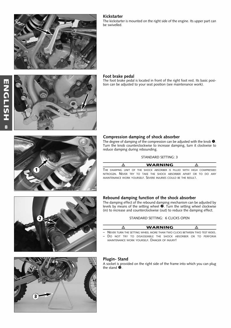
KickstarterThe kickstarter is mounted on the right side of the engine. Its upper part canbe swivelled.
Foot brake pedalThe foot brake pedal is located in front of the right foot rest. Its basic posi-tion can be adjusted to your seat position (see maintenance work).
Compression damping of shock absorberThe degree of damping of the compression can be adjusted with the knob 1.Turn the knob counterclockwise to increase damping, turn it clockwise toreduce damping during rebounding.
STANDARD SETTING: 3
� WARNING �THE DAMPING UNIT OF THE SHOCK ABSORBER IS FILLED WITH HIGH COMPRESSEDNITROGEN. NEVER TRY TO TAKE THE SHOCK ABSORBER APART OR TO DO ANYMAINTENANCE WORK YOURSELF. SEVERE INJURIES COULD BE THE RESULT.
Rebound damping function of the shock absorberThe damping effect of the rebound damping mechanism can be adjusted bylevels by means of the setting wheel 2. Turn the setting wheel clockwise(in) to increase and counterclockwise (out) to reduce the damping effect.
STANDARD SETTING: 6 CLICKS OPEN
� WARNING �– NEVER TURN THE SETTING WHEEL MORE THAN TWO CLICKS BETWEEN TWO TEST RIDES. – DO NOT TRY TO DISASSEMBLE THE SHOCK ABSORBER OR TO PERFORM
MAINTENANCE WORK YOURSELF. DANGER OF INJURY!
Plugin- StandA socket is provided on the right side of the frame into which you can plugthe stand 3.
2
3
1

EN
GLIS
H
9

EN
GLIS
H
10
GENERAL TIPS AND WARNINGS FOR STARTING THE MOTORCYCLE
� WARNING �– HAVE YOUR YOUNGSTER WEAR PROPER PROTECTIVE GEAR WHENEVER
HE OR SHE RIDES THE MOTORCYCLE: HELMET, EYE PROTECTION, CHEST,BACK, ARM AND LEG PROTECTORS, GLOVES AND BOOTS. TO SET AGOOD EXAMPLE, BE SURE TO WEAR PROTECTIVE GEAR YOURSELFWHENEVER RIDING A MOTORCYCLE!
– ONLY USE ACCESSORY PARTS RECOMMENDED BY KTM.– THE FRONT AND REAR WHEEL ARE ONLY ALLOWED TO BE TIRED WITH
TIRES THAT HAVE THE SAME PROFILE TYPE.– YOUR YOUNGSTER'S DRIVING SPEED SHOULD ALWAYS BE ADJUSTED TO
HIS/HER DRIVING SKILLS AS WELL AS TO THE TERRAIN.– YOUR YOUNGSTER SHOULD NEVER BE ALLOWED TO RIDE THE
MOTORCYCLE WITHOUT SUPERVISION.– REPLACE THE HELMET VISOR OR GOGGLE GLASSES EARLY ENOUGH.
WHEN LIGHT SHINES DIRECTLY ON A SCRATCHED VISOR OR GOGGLES,YOU WILL BE PRACTICALLY BLIND.
– NEVER LEAVE YOUR MOTORCYCLE WITHOUT SUPERVISION AS LONG ASTHE ENGINE IS RUNNING.
� WARNING �– SX MODELS ARE DESIGNED FOR ONE PERSON ONLY. PASSENGERS ARE
NOT ALLOWED.– THESE MODELS DO NOT COMPLY WITH THE REGULATIONS AND SAFETY
STANDARDS ESTABLISHED BY THE LAW. THEREFORE, THEY ARE NOT PER-MITTED ON PUBLIC ROADS.
– ALWAYS KEEP IN MIND THAT OTHER PEOPLE FEEL MOLESTED BY EXCES-SIVE NOISE.
Instructions for the first ride– Verify that your KTM dealer performed the PREPARATION
OF VEHICLE jobs (see Customer Service Manual).– Before your youngster takes his or her first ride, explain how
each of the controls works and check if your youngster hasunderstood what you explained. We recommend to reviewthe entire owner’s manual with your youngster item by item,paying particular attention to the specially marked warningsand pointing out the danger of injury.
– Adjust the clutch lever, hand lever and foot brake pedal soyour child can operate them easily!
– To prevent injury, teach your youngster the basic riding skillson soft ground, e.g. on a meadow or in the garden. Be surethat there is room enough to maneuver, and that no otherriders are close.
– To ensure that your youngster gets the feel of the handbrake, have your youngster operate the hand brake whileyou push the motorcycle. Do not start the engine beforeyour youngster has learned to apply hand brake with appro-priate pressure.
– To familiarize your youngster with the operation of the handbrake let him or her practice to operate the hand brake whileyou are pushing the motorcycle. Do not start the enginebefore he or she is thoroughly familiar with the use of thehand brake.
– Initially, your youngster should ride back and forth betweentwo persons who help the young rider to stop the motorcy-cle. However, you should also teach your youngster how tostop the motorcycle himself/herself.
– To improve his/her riding skills, your youngster should prac-tise riding the motorcycle standing on the footpegs or toriding at the slowest possible speed. Additionally, you canarrange a series of obstacles and have your youngster drivearound them, etc.
– Pay attention to the running-in procedure.
Running in– Even very precisely machined sections of engine components
have rougher surfaces than components which have beensliding across one another for quite some time. Therefore,every engine needs to be broken in. For this reason, duringits first 30 minutes the engine must not be revved up to itsperformance limits.
– Apply low but changing loads for running-in. – DO NOT DRIVE AT FULL LOAD FOR THE FIRST 30 MINUTES!

EN
GLIS
H
11
DRIVING INSTRUCTIONS
What you should check before each startWhen you start off, the motorcycle must be in a perfect technical condition.For safety reasons, you should make it a habit to perform an overall check ofyour motorcycle before each start.The following checks should be performed:
1 CHECK TRANSMISSION OIL LEVEL.A lack of gear oil leads to premature wear and finally results in destruc-tion of the gear wheels.
2 FUELCheck that there is sufficient fuel in the tank; when closing the filler cap,check that the tank venting hose is free of kinks.
3 CHAINA loose chain was fall off the chain wheels; an extremely worn chain maytear, and insufficient lubrication may result in unnecessary wear of thechain and chain wheels.
4 TIRESCheck for damaged tires. Tires showing cuts or dents must be replaced.Also check the air pressure. Insufficient tread and incorrect air pressuredeteriorate the driving performance.
5 BRAKESCheck the correct functioning of the braking system. Verify that there issufficient brake fluid in the reservoir. The reservoirs have been designedin such a way that brake fluid does not need to be refilled even when thebrake pads are worn. If the level of brake fluid falls below the minimumvalue, this indicates a leak in the braking system or completely worn outbrake pads. Always have the brake system checked by a KTM workshopto avoid brake failure.Also check the state of the brake hose and the thickness of the brakelinings.Check free travel at the hand brake lever and foot brake lever.
� WARNING �IF THE RESISTANCE IN THE HAND BRAKE LEVER FEELS “SPONGY” (TOO MUCH PLAY),THIS IS AN INDICATION THAT SOMETHING IS WRONG WITH THE BRAKE SYSTEM. DON’TLET YOUR CHILD RIDE THE MOTORCYCLE ANYMORE WITHOUT FIRST HAVING THE BRAKESYSTEM LOOKED OVER BY A KTM DEALER.
6 CABLESCheck correct setting and easy running of all control cables.
7 COOLING FLUIDCheck the level of cooling fluid when the engine is cold.
EN
GLIS
H
12
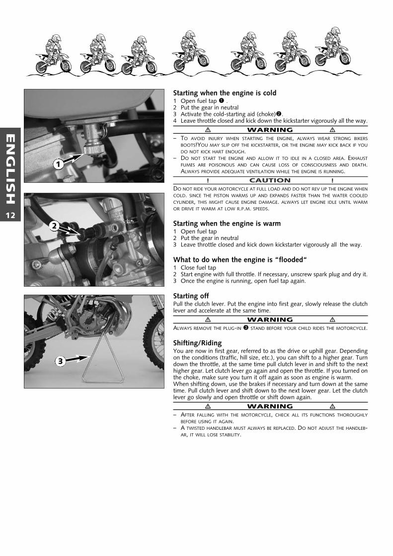
Starting when the engine is cold1 Open fuel tap 1 .2 Put the gear in neutral3 Activate the cold-starting aid (choke)2.4 Leave throttle closed and kick down the kickstarter vigorously all the way.
� WARNING �– TO AVOID INJURY WHEN STARTING THE ENGINE, ALWAYS WEAR STRONG BIKERS
BOOTS!YOU MAY SLIP OFF THE KICKSTARTER, OR THE ENGINE MAY KICK BACK IF YOUDO NOT KICK HART ENOUGH.
– DO NOT START THE ENGINE AND ALLOW IT TO IDLE IN A CLOSED AREA. EXHAUSTFUMES ARE POISONOUS AND CAN CAUSE LOSS OF CONSCIOUSNESS AND DEATH.ALWAYS PROVIDE ADEQUATE VENTILATION WHILE THE ENGINE IS RUNNING.
! CAUTION !DO NOT RIDE YOUR MOTORCYCLE AT FULL LOAD AND DO NOT REV UP THE ENGINE WHENCOLD. SINCE THE PISTON WARMS UP AND EXPANDS FASTER THAN THE WATER COOLEDCYLINDER, THIS MIGHT CAUSE ENGINE DAMAGE. ALWAYS LET ENGINE IDLE UNTIL WARMOR DRIVE IT WARM AT LOW R.P.M. SPEEDS.
Starting when the engine is warm1 Open fuel tap2 Put the gear in neutral3 Leave throttle closed and kick down kickstarter vigorously all the way.
What to do when the engine is “flooded“1 Close fuel tap2 Start engine with full throttle. If necessary, unscrew spark plug and dry it.3 Once the engine is running, open fuel tap again.
Starting offPull the clutch lever. Put the engine into first gear, slowly release the clutchlever and accelerate at the same time.
� WARNING �ALWAYS REMOVE THE PLUG-IN 3 STAND BEFORE YOUR CHILD RIDES THE MOTORCYCLE.
Shifting/RidingYou are now in first gear, referred to as the drive or uphill gear. Dependingon the conditions (traffic, hill size, etc.), you can shift to a higher gear. Turndown the throttle, at the same time pull clutch lever in and shift to the nexthigher gear. Let clutch lever go again and open the throttle. If you turned onthe choke, make sure you turn it off again as soon as engine is warm.When shifting down, use the brakes if necessary and turn down at the sametime. Pull clutch lever and shift down to the next lower gear. Let the clutchlever go slowly and open throttle or shift down again.
� WARNING �– AFTER FALLING WITH THE MOTORCYCLE, CHECK ALL ITS FUNCTIONS THOROUGHLY
BEFORE USING IT AGAIN.– A TWISTED HANDLEBAR MUST ALWAYS BE REPLACED. DO NOT ADJUST THE HANDLEB-
AR, IT WILL LOSE STABILITY.
1
2
3
EN
GLIS
H
13
! CAUTION !– DRIVING A COLD ENGINE AT HIGH SPEED WILL REDUCE THE LIFE OF THE
ENGINE. WE RECOMMEND TO WARM THE ENGINE UP AT A MEDIUMENGINE SPEED FOR SEVERAL MINUTES BEFORE SWITCHING TO FULLLOAD.
– NEVER HAVE THE THROTTLE WIDE OPEN WHEN CHANGING DOWN TO ALOWER GEAR. THE ENGINE WILL OVERREV, DAMAGING THE VALVES. INADDITION, THE REAR WHEEL BLOCKS SO THAT THE MOTORCYCLE CANEASILY GET OUT OF CONTROL.
– IF THE ENGINE RUNS WITHOUT THROTTLE DURING LONGER DOWNHILLTRAVEL, THE ENGINE SHOULD BE ACCELERATED OCCASIONALLY TOENSURE THAT IT IS SUPPLIED WITH SUFFICIENT LUBRICANT WHICH ISMIXED IN THE FUEL.
– IN THE EVENT THAT, WHILE YOUR CHILD IS RIDING ON THE MOTORCY-CLE, YOU NOTICE ANY UNUSUAL OPERATION-RELATED NOISE, YOURCHILD SHOULD STOP IMMEDIATELY, TURN THE ENGINE OFF, ANDCONTACT AN AUTHORIZED KTM DEALER.
BrakingTurn off the gas and apply the hand and foot brakes at thesame time. When driving on sandy, wet or slippery ground usemainly the rear wheel brake. Always brake with feeling,blocking wheels can cause you to skid or fall. Also change downto lower gears depending on your speed.
� WARNING �– IN CASE OF RAIN, AFTER WASHING THE MOTORCYCLE, AFTER RIDES
THROUGH WATER AND IN CASE OF RIDES ON WET OFF-ROAD TRACKS,HUMID OR DIRTY BRAKE DISCS CAN DELAY THE BRAKING EFFECT. THEBRAKES MUST BE PULLED UNTIL THEY ARE DRY OR CLEAN.
– DIRTY BRAKE DISCS CAUSE INCREASED TEAR OF BRAKE PADS AND BRAKEDISCS.
– WHEN YOU BRAKE, THE BRAKE DISCS, BRAKE PADS, BRAKE CALIPER ANDBRAKE FLUID HEAT UP. THE HOTTER THESE PARTS GET, THE WEAKER THEBREAKING EFFECT. IN EXTREME CASES, THE ENTIRE BRAKING SYSTEM CANFAIL.
StoppingBrake motorcycle and shift gears to idling. To switch off theengine, depress short circuit switch until the engine stops. Closefuel tap.
� WARNING �MOTORCYCLE ENGINES PRODUCE A GREAT AMOUNT OF HEAT WHILERUNNING. THE ENGINE, EXHAUST PIPE, MUFFLER, BRAKE ROTORS, ANDSHOCK ABSORBERS CAN BECOME VERY HOT. DO NOT TOUCH ANY OFTHESE PARTS AFTER STARTING THE MOTORCYCLE, AND TAKE CARE TO PARKIT WHERE PEDESTRIANS ARE NOT LIKELY TO TOUCH IT AND GET BURNED.
! CAUTION !
– CLOSE THE FUEL TAP WHEN LEAVING YOUR VEHICLE. OTHERWISE THECARBURETOR MAY GET FLOODED AND FUEL WILL ENTER THE ENGINE.
– THE PLUGIN- STAND IS ONLY DESIGNED FOR THE WEIGHT OF THEMOTORCYCLE. IF YOU GET ON YOUR MOTOR-CYCLE AND THUS PUTADDITIONAL WEIGHT ON THE MOTORCYCLE, THE PLUGIN- STAND ORTHE FRAME CAN BE DAMAGED OR THE MOTORCYCLE MAY FALL ON THESIDE.
Refueling, fuelOil (high-grade two-stroke engine oil; i.e. Shell Advance Racing X)must be mixed with the fuel (ROZ 95) at a mixing ratio of 1:40.
� WARNING �GASOLINE IS HIGHLY FLAMMABLE AND POISONOUS. EXTREME CAUTIONSHOULD BE USED WHEN HANDLING GASOLINE. NEVER REFUEL THEMOTORCYCLE NEAR OPEN FLAMES OR BURNING CIGARETTES. ALWAYSSWITCH OFF THE ENGINE BEFORE REFUELING. BE CAREFUL NOT TO SPILLGASOLINE ON THE ENGINE OR EXHAUST PIPE WHILE THE ENGINE IS HOT.WIPE UP SPILLS PROMPTLY. IF GASOLINE IS SWALLOWED OR SPLASHED INTHE EYES, SEEK A DOCTOR’S ADVICE IMMEDIATELY.
! CAUTION !– ONLY USE PREMIUM-GRADE GASOLINE ROZ 95 MIXED WITH HIGH-
GRADE TWO-STROKE ENGINE OIL. OTHER TYPES OF GASOLINE CANCAUSE ENGINE FAILURE.
– ONLY USE KNOWN BRANDS OF HIGH-GRADE 2-STROKE ENGINE OIL(SHELL ADVANCE RACING X).
– NOT ENOUGH OIL OR LOW-GRADE OIL CAN CAUSE EROSION OF THEPISTON. WHEN USING TOO MUCH OIL, THE ENGINE MAY START SMO-KING AND FOUL THE SPARK PLUG.
– FUEL EXPANDS WHEN ITS TEMPERATURE RISES. THEREFORE DO NOT FILLTHE TANK TO THE TOP. (SEE FIG.)
40 mm

EN
GLIS
H
14
PERIODIC MAINTENANCE SCHEDULEServiceevery
20 hoursonce a year
MAINTENANCE WORK DONE BY KTM AUTHORISED WORKSHOPS IS NOT A SUBSTITUTE FOR CARE AND CHECKS DONE BY THE RIDER!
A clean motorcycle can be checked more quickly which saves money!
Check transmission oil level ●
Change transmission oil ●
Check spark plug, change it if necessary, set electrode gap ●
Check carburetor for a tight fit at intake flange ●
Check the intake flange and carburetor connection boot for cracks and tightness ●
Check idle setting when engine is warm ●
Check the bleeder hose for damage, kinkless installation and passage ●
Check cooling system for leaks, antifreeze protection ●
Check exhaust system for leaks and suspension ●
Check actuating cables for damage, smooth operation, and kinkless ●
arrangement, and adjust and lubricateCheck oil level of the clutch master cylinder ●
Clean air filter and air filter box ●
Check brake fluid level, lining thickness, brake discs ●
Check brake lines for damage and leaks ●
Check functiuon/adjust smooth operation, free travel of handbrake levers ●
Check screws of brake system for a tight fit ●
Check suspension strut and fork for leaks and a proper function ●
Clean dust bellows ●
Bleed fork legs ●
Check swinging-fork pivot ●
Check/adjust steering-head bearing ●
Check all chassis screws for a tight fit (fork plates, axle nuts, ●
swinging-fork pivot, suspension strut)Check spoke tension and rim joint ●
Check tire condition and inflation pressure ●
Check chain, chain wheels, chain wheel, chain joint guides for wear, tight fit, and tension ●
Lubricate chain ●
Check wheel bearings for play ●
IMPORTANT RECOMMENDED MAINTENANCE PROCEDURES TO BE PERFORMED BASED ON A SEPARATE SUPPLEMENTARY ORDER
Perform complete fork maintenance ●
Perform complete suspension strut maintenance ●
Clean and lubricate the swinging-arm bearing ●
Clean and lubricate the steering-head bearing and sealing elements ●
Clean and adjust carburator ●
Change hydrulic clutch fluid ●
Change brake fluid ●
WH
EELS
CH
ASS
ISBR
EAK
SAD
D-O
N-P
ARTS
ENG
INE
65 SX
once a year
CARB
URET
OR

EN
GLIS
H
15
VITAL CHECKS AND CARE PROCEDURES TO BE CONDUCTED BY THE OWNER OR THE MECHANIC
Check transmission oil level ●
Check coolant level ●
Check brake fluid level ●
Check brake pads for wear ●
Check brake performance ● ●
Lubricate and adjust actuating ga scable and nipples ●
Remove and clean dust sleeves of telescopic fork at regular intervals ●
Bleed fork legs regularly ●
Clean and lubricate chain, check tension and readjust it if necessary ● ●
Clean air filter and filter box ●
Check tire inflation pressure and wear ●
Check fuel line for leaks ●
Drain and clean float chamber ●
Verify smooth operation of all controls ●
Treat exposed metal components (except for the brake and exhaust systems) ●
with wax-based anti-corrosion agentsTreat all electric plug-in connections with contact spray ●
Check all screws, nuts, and hose clamps for their tight fit at regular intervals ●
for
cros
sco
untr
y us
e
once
a y
ear
afte
r ev
ery
clea
ning
befo
re e
ach
star
t
as of 03.2002
RECOMMENDED INSPECTION OF THE 65 SX ENGINE BY YOUR KTM WORKSHOP(ADDITIONAL ORDER FOR THE KTM’S WORKSHOP)
Check the reed-type intake valve for wear ● ● ● ● ● ●
Check the clutch shoes for wear ● ● ● ● ● ●
Check the length of the clutch springs ● ● ● ● ● ●
Check the cylinder and piston for wear ● ● ● ● ● ●
Check the eccentricity of the crankshaft journal ● ● ● ● ● ●
Check the radial clearance of the conrod bearings ● ● ●
Check the radial clearance of the piston pin main bearing ● ● ●
Check the crankshaft main bearing for wear ● ● ●
Replace the crankshaft bearings and conrod bearings ● ● ●
Check the entire transmission including roller and bearings for wear ● ● ●
30hours
45hours
60hours
90hours
120hours
135hours
NOTE: IF THE INSPECTION ESTABLISHES THAT PERMISSIBLE TOLERANCES ARE EXCEEDED, THE RESPECTIVE COMPONENTS MUST BE REPLACED.

EN
GLIS
H
16
Checking and adjusting the steering head bearing *Check steering head bearing for play periodically. To check, put motorcycleon the stand so that the front wheel is off the ground. Now try to move thefork forward and backward. For readjusting, loosen the three clamp screws1of the top triple clamp and turn steering stem bolt clockwise 2 until there isno more play. Don’t tighten the steering stem bolt all the way, otherwise thebearings will be damaged. With a plastic hammer, lightly rap on the tripleclamp to release tension. Retighten the three clamp screws to 20 Nm.
� WARNING �IF THE STEERING HEAD BEARING IS NOT ADJUSTED TO BE FREE OF PLAY, THE MOTORCYCLEWILL EXHIBIT UNSTEADY DRIVING CHARACTERISTICS AND CAN GET OUT OF CONTROL.
! CAUTION !IF YOU DRIVE WITH PLAY IN THE STEERING HEAD BEARING FOR LONGER PERIODS, THEBEARINGS AND SUBSEQUENTLY THE BEARING SEATS IN THE FRAME WILL BE DESTROYED.
The steering head bearings should be regreased at least once a year (i.e. Shell Advance Grease).
� WARNING �ALL MAINTENANCE AND ADJUSTMENT OPERATIONS THAT ARE MARKED WITH AN ASTERISK * REQUIRE SPECIALIST KNOWLEDGE. FOR YOUR OWN SECURITY, LET THESE TASKS BE CARRIED OUT BY A KTM-DEALERWHERE YOUR MOTORCYCLE WILL BE OPTIMALLY SERVICED BY APPROPRIATELY QUALIFIED, SKILLED STAFF.
! CAUTION !– WHEN CLEANING THE MOTORCYCLE, DO NOT USE A HIGH PRESSURE CLEANING UNIT IF POSSIBLE, OTHERWISE WATER WILL PENETRATE THE BEARINGS, CAR-
BURETOR, ELECTRIC CONNECTORS, ETC.– WHEN TRANSPORTING YOUR KTM, ENSURE THAT IT IS HELD UPRIGHT WITH RESTRAINING STRAPS OR OTHER MECHANICAL FASTENING DEVICES AND THAT
THE FUEL TAP IS IN THE OFF POSITION - IF THE MOTORCYCLE SHOULD FALL OVER, NO FUEL CAN LEAK FROM THE CARBURETOR OR FUEL TANK– ONLY USE SPECIAL SCREWS WITH AN APPROPRIATE THREAD LENGTH SUPPLIED BY KTM TO FIX THE SPOILERS ON THE TANK. USING OTHER SCREWS OR
LONGER SCREWS CAN CAUSE LEAKS IN THE TANK THROUGH WHICH FUEL CAN FLOW OUT.– DO NOT USE TOOTHED WASHERS OR SPRING RINGS WITH THE ENGINE FASTENING SCREWS, AS THESE WORK INTO THE FRAME PARTS AND KEEP WORKING
LOOSE. INSTEAD, USE SELF-LOCKING NUTS.– LET YOUR MOTORCYCLE COOL DOWN BEFORE BEGINNING ANY MAINTENANCE WORK IN ORDER TO AVOID GETTING BURNED.– DISPOSE OF OILS, FATTY MATTERS, FILTERS, FUELS, WASHING DETERGENTS, ETC. PROPERLY.– UNDER NO CIRCUMSTANCES MAY USED OIL BE DISPOSED OF IN THE SEWAGE SYSTEM OR IN THE OPEN COUNTRYSIDE. 1 LITER OF USED OIL CONTAMINA-
TES 1,000,000 LITERS OF WATER.
MAINTENANCE WORK ON CHASSIS AND ENGINE
2
1

EN
GLIS
H
17
Basic suspension setup for the weight of the driverTo achieve maximum handling performance and to prevent the telescopicfork and shock absorber from being damaged, the basic setup of the sus-pension components must be suitable for your child's weight. At delivery,KTM's 65 SX motorcycles are set to accommodate a driver weighing 35 – 45kg (wearing full protective clothing). If your child's weight exceeds or fallsshort of this range, you will need to adjust the spring preload for the teles-copic fork and shock absorber accordingly.To adjust, check the sag of the shock absorber and telescopic fork. Themotorcycle should be filled up and your child should be wearing full protec-tive clothing.
To determine the sag of the shock absorber– Jack up the motorcycle until the rear wheel no longer touches the ground.– Measure the vertical distance between the rear wheel axle and a fixed
point (e.g. a mark on the side cover) and write it down as dimension A.– Place the motorcycle on the ground again.– Have your child sit on the motorcycle in a normal seating position (feet on
the footrests) wearing full protective clothing and bounce up and down afew times to allow the rear wheel suspension to become level.
– Holding your child and the bike, have another person measure thedistance between the same two points with the load on the motorcycle toestablish dimension B.
– The sag is the difference between dimensions A and B.
EXAMPLE:Motorcycle jacked up (dimension A) . . . . . . . . . . . . . . . . . . . . . . .430 mmMotorcycle on ground with driver seated (dimension B) . . . . . . .– 340 mmSag . . . . . . . . . . . . . . . . . . . . . . . . . . . . . . . . . . . . . . . . . . . . . . . .90 mm
The sag should be 90 mm (± 5 mm)If the sag is lower, the spring preload of the shock absorber must be redu-ced, if the sag is higher, the spring preload must be increased..
To determine the sag of the telescopic fork – Jack up the motorcycle until the rear wheel no longer touches the ground.– Measure the distance between the upper edge of the slider tube and the
triple clamp and write it down as dimension C.– Have your child sit on the motorcycle in a normal seating position (feet on
the footrests) wearing full protective clothing, and bounce up and downa few times to allow the telescopic fork to become level.
– Holding your child and the bike, have another person measure thedistance between the same two points with the load on the motorcycle toestablish dimension D.
– The sag is the difference between dimensions C and D.
EXAMPLE:Motorcycle jacked up (dimension C) . . . . . . . . . . . . . . . . . . . . . . .200 mmMotorcycle on ground with driver seated (dimension D) . . . . . . .– 160 mmSag . . . . . . . . . . . . . . . . . . . . . . . . . . . . . . . . . . . . . . . . . . . . . . . .40 mm
The sag should be 45 mm (± 5 mm). If the sag is lower, the spring preload of the telescopic fork must be reduced,if the sag is higher, the spring preload must be increased.The preload on the fork spring is determined by the length of preload spa-cer 1. If an adjustment is necessary, demount the fork legs, remove theplugs and shorten the pretensioning sleeves or replace with longer ones.
A
B
C
D
1

EN
GLIS
H
18
Breather plug front forkThe telescopic fork should be ventilated at regular intervals. Jack up themotorcycle until the front wheel no longer touches the ground. Unscrewvent screws 1 several turns to let any excess pressure escape from the inside of the fork.
! CAUTION !EXCESSIVE PRESSURE IN THE INTERIOR OF THE FORK CAN CAUSE LEAKS IN THE FORK. IFYOUR FORK IS LEAKING, IT IS RECOMMENDED TO OPEN THE BREATHER PLUGS BEFOREHAVING THE SEALS REPLACED.
Cleaning the dust sleeves of the telescopic forkThe dust-protection bellows 2 are to remove dust and coarse dirt particlesfrom the fork tube. However, after some time, dirt may also get in behindthe dust-protection bellows. If this dirt is not removed, the oil sealing ringslocated behind it may start to leak.Use a screwdriver to lift the dust-protection bellows out of the outer tubesand slide them downward.
Clean dust-protection bellows, outer tubes, and fork tubes thoroughly, andoil them thoroughly with silicone spray or engine oil. Then, push dust-pro-tection bellows into the outer tubes by hand.
How to change the handlebar positionThe handlebar position can be readjusted by 22 mm. Thus, you can put thehandlebar in the position that is the most convenient for you. The upper tri-ple clamp 3 includes 2 bores arranged at a distance of 15 mm (0.6 in) fromone another. The bores at the handlebar support 4 are offset from the cen-ter by 3.5 mm (0.13 in). Accordingly, you can mount the handlebar in 4 different positions.
For this purpose, remove screws 5 of the handlebar clamps and screws 6of the handlebar support. Position handlebar support, and tighten screws 6to 40 Nm. Mount handlebar and handlebar clamps, and tighten screws 5to 20 Nm. The gap between the handlebar support and handlebar clampsshould be the same size in the front and in the rear.
� WARNING �THE SCREWS 6 MUST BE SECURED WITH LOCTITE 243.
2
1
3
4
5
6
15 mm 3,5 mm

EN
GLIS
H
19
Changing spring preloading of the shock absorberThis is easily done.NOTE:Before changing the spring preload note down the basic setting, e.g. howmany threads are visible above the adjusting ring.
Loosen the locking ring 1 with the hook spanner. Change the spring preload with the adjusting ring 2 and re-tighten the locking ring 1.
BASIC SETTING – SPRING PRELOAD7 mm (0.3 in)
Checking chain tensionSet the motorcycle on the plug-in stand.Press the chain down on the upper end of the chain sliding component.The distance between the chain and the swing arm should be approx. 3mm.The lower part of the chain should be tightened.
� WARNING �– IF THE CHAIN IS TOO TIGHT THE SECONDARY TRANSMISSION COMPONENTS (CHAIN,
SPROCKETS, BEARINGS OF THE TRANSMISSION AND OF THE REAR WHEEL) WILL BE PUTUNDER ADDITIONAL STRAIN THAT CAN, IN ADDITION TO PREMATURE WEAR, ALSOCAUSE CHAIN BREAKAGE.
– IF THE CHAIN IS NOT TIGHT ENOUGH IT CAN SLIP OFF THE SPROCKETS AND BLOCK THEREAR WHEEL OR DAMAGE THE ENGINE.
– IN BOTH CASES THE RIDER IS VERY LIKELY TO LOSE CONTROL OF THE MOTORCYCLE.
Correcting chain tensionUndo the hexagon nut 3, then undo both counter nuts 4 and turn the leftand the right tensioning screws 5 equally far. Then retighten the counternuts 4.Before tightening the hexagon nut 3 make sure that the chain adjuster6 is properly resting against the tensioning screws 5 and that the rearwheel is properly aligned with the front wheel.Tighten the hexagon nut 3 to 50 Nm.
� WARNING �– IF YOU DON’T HAPPEN TO HAVE A TORQUE WRENCH AT HAND, MAKE SURE YOU HAVE
THE TIGHTENING TORQUE CORRECTED BY A KTM DEALER AS SOON AS POSSIBLE. ALOOSE AXLE MAY LEAD TO AN UNSTABLE DRIVING BEHAVIOR OF YOUR MOTORCYCLE.
– TIGHTEN THE HEXAGON NUT TO THE REQUIRED TORQUE. A LOOSE WHEEL SPINDLEMAY LEAD TO AN UNSTABLE BEHAVIOR OF YOUR MOTORCYCLE.
Chain maintenanceFor long chain life, good maintenance is very important. The chain shouldbe cleaned in fireproof solvent regularly and afterwards treated with hotgrease or chain spray ( Shell Advance Bio Chain).
� WARNING �NO LUBRICATION IS ALLOWED TO REACH THE REAR TIRE OR THE BRAKE DISKS, OTHER-WISE THE ROAD ADHERENCE AND THE REAR WHEEL BRAKING EFFECTS WOULD BESTRONGLY REDUCED AND THE MOTORCYCLE COULD EASILY LOSE CONTROL.
! CAUTION !WHEN MOUNTING THE CHAIN MASTERLINK CLIP, THE CLOSED SIDE OF THE MASTERLINKCLIP MUST POINT IN RUNNING DIRECTION.
Also check sprockets and chain guides for wear, and replace if necessary.
✓
4
34
3 mm
1
2
5
6
5
6

EN
GLIS
H
20
General information about KTM disc brakes
BRAKE CALIPERS:If the front brake caliper is removed, the screws must be secured withLoctite 243 when mounted and tightened to 20 Nm.
BRAKE FLUID RESERVOIRS:The brake fluid reservoirs on front and rear wheel brakes have been designed in such a way that even if the brake pads are worn it is not neces-sary to top up the brake fluid. If the brake fluid level drops below the mini-mum level either the brake system has a leak or the brake pads are com-pletely worn. In this case, consult an authorized KTM dealer immediately.
BRAKE FLUID:KTM fills the brake system with ”Shell Advance Brake DOT 5.1”, one of thebest brake fluids currently available. We recommend that you continue touse it. DOT 5.1 brake fluid is based on glycol ether and of an amber color.If you do not have any DOT 5.1 for refilling, you may use DOT 4 brakefluid. DOT 4 shown on the lid means minimum standard. However, youshould replace it as soon as possible by DOT 5.1.
� WARNING �HAVE THE BRAKE FLUID CHANGED AT LEAST ONCE ANNUALLY. IF YOU WASH YOURMOTORCYCLE OFTEN, THE BRAKE FLUID SHOULD BE CHANGED EVEN MORE FREQUENTLY.BRAKE FLUID TENDS TO ABSORB WATER. THEREFORE, VAPOR POCKETS MAY FORM IN"OLD" BRAKE FLUIDS EVEN AT LOW TEMPERATURES, CAUSING THE BRAKE SYSTEM TOFAIL.
BRAKE DISCS:Due to wear, the thickness of the brake disc in the area of the contact face 1 of the brake pads decreases. At their thinnest point A, the brakediscs must not be more than 0.40 mm (0.016 in) thinner than the pad'snominal thickness. Measure the nominal thickness in a location B outsidethe contact face. Check wear in several locations.
� WARNING �– BRAKE DISCS SUFFERING FROM WEAR GREATER THAN 0.40 MM (0.016 IN) CONSTI-
TUTE A SAFETY RISK. HAVE THE BRAKE DISCS REPLACED IMMEDIATELY AS SOON ASTHEY REACH THE WEAR LIMIT.
– HAVE ANY REPAIRS ON THE BRAKE SYSTEM BE PERFORMED BY A KTM DEALER.
Adjusting free travel of the hand brake leverFree travel of the hand brake lever may be readjusted by using the adjust-ment screw 2. In this way, the position of the point of pressure (i.e. theresistance you feel on the hand brake lever when the brake pads are pressed against the brake disc) can be adjusted for any hand size.
! CAUTION !AT THE HAND BRAKE LEVER, FREE TRAVEL MUST AT LEAST BE 3 MM (0.1 IN). ONLY THENMAY THE PISTON IN THE HAND BRAKE CYLINDER BE MOVED (TO BE RECOGNIZED BY THEGREATER RESISTANCE OF THE HAND BRAKE LEVER). IF THIS FREE TRAVEL IS NOTPROVIDED, PRESSURE WILL BUILD UP IN THE BRAKING SYSTEM, AND THE FRONT-WHEELBRAKE MAY FAIL DUE TO OVERHEATING.
min. 3 mm
�
DOT5.1
DOT5
✓ ✕
2
A
B
1

EN
GLIS
H
21
Checking brake fluid level - front brakeThe brake fluid reservoir is combined with the hand brake cylinder on thehandlebar and provided with an inspection glass. When the brake fluidreservoir is in a horizontal position, the brake fluid level should not dropbelow the "MIN" mark on the inspection glass.
� WARNING �DROPPING OF THE BRAKE FLUID LEVEL BELOW THE "MIN" MARK INDICATES LEAKS INTHE BRAKE SYSTEM OR TOTALLY WORN BRAKE PADS. IN THIS CASE, CONTACT ALICENSED KTM DEALER IMMEDIATELY.
Refilling front brake fluid reservoir *When the brake fluid falls to the middle of the inspection glass, new brakefluid has to be added.Loosen screws 1 and remove lid 2 and membrane 3. Place hand brake cylinder in a horizontal position and fill the brake fluidreservoir to 5 mm (0.2 in) below the rim with clean brake fluid DOT 5.1(Shell Advance Brake DOT 5.1). Replace membrane and lid, tighten screws.Rinse off spilled or overflowing brake fluid with water.
� WARNING �– NEVER USE DOT 5 BRAKE FLUID! IT IS BASED ON SILICONE OIL AND OF A PURPLE
COLOR. SEALS AND BRAKE HOSES MUST BE ESPECIALLY ADAPTED TO IT.– STORE BRAKE FLUID OUT OF REACH OF CHILDREN.– BRAKE FLUID CAN CAUSE SKIN IRRITATION. AVOID CONTACT WITH SKIN AND EYES. IF
YOU GET BRAKE FLUID IN YOUR EYES, RINSE WITH PLENTY OF WATER AND CONSULT ADOCTOR !
! CAUTION !– DON’T LET BRAKE FLUID GET IN CONTACT WITH PAINT, IT IS AN EFFECTIVE PAINT
REMOVER.– USE ONLY CLEAN BRAKE FLUID TAKEN FROM A TIGHTLY SEALED CONTAINER.
Checking the front brake padsThe brake pads can be inspected from below. The linings nust be at least1 mm (0.04 in) thick.
� WARNING �AT THEIR MOST WORN POINT BRAKE PAD LININGS SHOULD NOT BE THINNER THAN 1 MM,OTHERWISE THEY COULD LEAD TO BRAKE FAILURE. FOR YOUR OWN SAFETY DON’T PUTOFF HAVING YOUR BRAKE PADS CHANGED.
! CAUTION !IF THE BRAKE PADS ARE REPLACED TOO LATE SO THAT THE LINING IS PARTLY OR ENTIRE-LY WORN, THE STEEL COMPONENTS OF THE BRAKE PAD WILL RUB AGAINST THE BRAKEDISC, THEREBY IMPARING THE BRAKING EFFECT AND DESTROYING THE BRAKE DISC.
5 mm
min.1 mm
1 1
2
3

EN
GLIS
H
22
Replacing the front brake pades*Remove the front wheel (see front wheel chapter).Press brake shoes apart with a suitable screwdriver to put the brake pistonsin their basic position.
Remove the lock washer 1 from the screw as well as fixing screw 2 andtake the brake shoes out of the brake caliper. Clean brake caliper thoroughly with compressed air.
Mount the right brake shoe and fix with screw. Mount the left brake shoeand tighten the screw to 10 Nm. Mount the lock washer. Align brake shoes,mount front wheel (see chapter: Mounting the front wheel).
� WARNING �– IT IS VERY IMPORTANT TO KEEP THE BRAKE DISK FREE FROM OIL AND FATTY MATTERS.
OTHERWISE, THE BRAKING EFFECT WOULD BE STRONGLY REDUCED.– AFTER ASSEMBLY, CHECK IF CIRCLIPS HAVE BEEN FITTED CORRECTLY.– HAVING PERFORMED ANY WORK ON THE BRAKING SYSTEM, ONE MUST ALWAYS
ACTUATE THE HAND BRAKE LEVER OR FOOT BRAKE LEVER, RESPECTIVELY SO AS TO ENSU-RE THAT THE BRAKE PADS WILL LIE AGAINST THE BRAKE DISK AND THE PRESSURE POINTIS ESTABLISHED.
– DO NOT UNSCREW ANY OTHER SCREWS ON THE BRAKE CALIPER OR YOU WILL HAVETO BLEED THE BRAKE SYSTEM.
Changing basic position of the brake pedal *The basic setting of the foot brake pedal can be changed by turning the endstop roller 3. Using the push rod 4, the free play on the foot brake pedalmust be set.Measured on the outside, the foot brake pedal must have 3-5 mm of freeplay before the push rod can move the piston in the brake cylinder (to berecognised from the resistance on the foot brake pedal).
! CAUTION !IF THIS CLEARANCE IS MISSING, PRESSURE ACCUMULATES IN THE BRAKING SYSTEM ANDTHE BRAKE PADS BEGIN TO RUB. THE BRAKING SYSTEM OVERHEATS AND CAN FAILCOMPLETELY IN EXTREME CASES.
1 2
3-5mm
3
4

EN
GLIS
H
23
Check rear brake fluid level The reservoir for the rear disc brake is located above the carburator. Thelevel of brake fluid may not fall below the “MIN” mark when the vehiclehas been left standing upright
� WARNING �IF THE BRAKE FLUID LEVEL DROPS BELOW MINIMUM EITHER THE BRAKE SYSTEM HAS A LEAKOR THE BRAKE PADS ARE COMPLETELY WORN. IN THIS CASE, CONSULT ANAUTHORIZED KTM DEALER IMMEDIATELY.
Refilling the rear brake fluid reservoir *For this purpose, it is recommended to remove the screw and to pull thebrake fluid reservoir outwards. Now the screw cap 1 and the rubber boot2 can be removed. Add brake fluid DOT 5.1 (Shell Advance Brake DOT5.1) until the brake fluid level reaches the ”MAX” mark, then mount thescrew cap together with the rubber boot. Restore the brake fluid reservoirto its original position and fix it with the screw. The connecting hose bet-ween the reservoir and the foot brake cylinder must be carefully positioned,preventing kinks and keeping a safe distance between the hose and theexhaust pipe. Spilled brake fluid must be rinsed off with water.
� WARNING �– NEVER USE DOT5 BRAKE FLUID! IT IS BASED ON SILICONE OIL IS OF A PURPLE
COLOR. SEALS AND BRAKE HOSES MUST BE ESPECIALLY ADAPTED TO IT.– STORE BRAKE FLUID OUT OF REACH OF CHILDREN.– BRAKE FLUID CAN CAUSE SKIN IRRITATION. AVOID CONTACT WITH SKIN AND EYES. IF
YOU GET BRAKE FLUID IN YOUR EYES, RINSE WITH PLENTY OF WATER AND CONSULTA DOCTOR.
! CAUTION !– DON’T LET BRAKE FLUID GET IN CONTACT WITH PAINT, IT IS AN EFFECTIVE PAINT
REMOVER.– USE ONLY CLEAN BRAKE FLUID TAKEN FROM A TIGHTLY SEALED CONTAINER.
Checking rear brake padsThe brake pads can be inspected from the rear. The thickness of the liningsmay not be less than 1 mm (0.04 in).
� WARNING �AT THEIR MOST WORN POINT BRAKE PAD LININGS SHOULD NOT BE THINNER THAN1 MM, OTHERWISE THEY COULD LEAD TO BRAKE FAILURE. FOR YOUR OWN SAFETYDON’T PUT OFF HAVING YOUR BRAKE PADS CHANGED.
! CAUTION !IF THE BRAKE PADS ARE REPLACED TOO LATE SO THAT THE LINING IS PARTLY OR ENTIRE-LY WORN, THE STEEL COMPONENTS OF THE BRAKE PAD WILL RUB AGAINST THE BRAKEDISC, THEREBY IMPARING THE BRAKING EFFECT AND DESTROYING THE BRAKE DISC.
Replacing rear brake pads *Remove the cover 3 and the locking ring 4. Using a punch, press the bolt 5 out of the brake caliper in an outward direction and remove ittogether with the leaf spring 6.Pull the brake pads upwards and out of the brake caliper. Clean the brakecaliper thoroughly with compressed air.Before installing the new brake pads push the brake pistons backwards withan appropriate screwdriver.
1
2
3 4
min.1 mm

EN
GLIS
H
24
Insert the new brake pads 1 into the brake caliper, position the leaf spring6, and secure it with the bolt 5. By tapping on the bolt, drive it into thebrake caliper up to the stop. Reattach locking ring 4 and cover 3.
� WARNING �– IT IS VERY IMPORTANT TO KEEP THE BRAKE DISK FREE FROM OIL AND FATTY MATTERS.
OTHERWISE, THE BRAKING EFFECT WOULD BE STRONGLY REDUCED.– AFTER ASSEMBLY, CHECK IF CIRCLIPS HAVE BEEN FITTED CORRECTLY.– HAVING PERFORMED ANY WORK ON THE BRAKING SYSTEM, ONE MUST ALWAYS
ACTUATE THE HAND BRAKE LEVER OR FOOT BRAKE LEVER, RESPECTIVELY SO AS TO ENSU-RE THAT THE BRAKE PADS WILL LIE AGAINST THE BRAKE DISK AND THE PRESSURE POINTIS ESTABLISHED.
Removing and installing front wheelTo remove the front wheel, jack the motorcycle up on its frame so that thefront wheel no longer touches the ground.Loosen the collar screw 7.Loosen the 2 clamping screws 8 on the fork fists.Hold the front wheel, pull out the wheel spindle 9.NOTICE: the wheel spindle can be pulled out more easily if you slide anopen-end wrench (17 mm) on to the flat portion A of the wheel spindle.Remove front wheel carefully from the fork.
! CAUTION !– DO NOT OPERATE THE HAND BRAKE WHEN THE FRONT WHEEL HAS BEEN
DISMOUNTED.– MAKE SURE THE BRAKE DISC IS ALWAYS ON TOP WHEN YOU LAY DOWN THE WHEEL,
OTHERWISE THE BRAKE DISC CAN BE DAMAGED.
Insert the front wheel in the fork and adjust to the right position.Mount the wheel spindle 9 and tighten the clamping screws on the rightfork leg slightly.Degrease the thread on the collar screw and apply Loctite 243.Mount the collar nut and tighten to 30 Nm.Take the motorcycle off the stand and bounce the fork hard a few times toalign the fork legs.Then tighten clamping screws to a max. torque of 10 Nm.
� WARNING �– IF YOU DON’T HAPPEN TO HAVE A TORQUE WRENCH AT HAND, MAKE SURE YOU HAVE
THE TIGHTENING TORQUE CORRECTED BY A KTM DEALER AS SOON AS POSSIBLE. ALOOSE AXLE MAY LEAD TO AN UNSTABLE DRIVING BEHAVIOR OF YOUR MOTORCYCLE.
– AFTER MOUNTING THE FRONT WHEEL, KEEP OPERATING THE HAND BRAKE UNTIL THEPRESSURE POINT RETURNS.
– IT IS VERY IMPORTANT TO KEEP THE BRAKE DISK FREE FROM OIL AND FATTY MATTERS,OTHERWISE THE BRAKING EFFECTS WOULD BE STRONGLY REDUCED.
– TIGHTEN THE HEXAGON NUT WITH THE REQUIRED TORQUE. A LOOSE WHEELSPINDLE MAY LEAD TO AN UNSTABLE BEHAVIOR OF YOUR MOTORCYCLE.
2
35
6
1
7
8
A
9

EN
GLIS
H
25
Removing and installing the rear wheelJack the motorcycle up by the frame.Remove the hexagon nut 1 of the wheel spindle together with the washer2 and remove the chain adjuster 3.Hold the rear wheel and pull out the wheel spindle.
Turn the rear wheel forwards and take the chain off the rear sprocket.Pull the rear wheel backwards.
To install the rear wheel reverse the procedure described above.Slightly grease the wheel spindle.Before tightening the hexagon nut 1 make sure that the chain adjusters 3are properly resting against the tensioning screws. Additionally, make surethat the rear wheel is properly aligned with the front wheel.Mount the hexagon nut and tighten to 50 Nm.
! CAUTION !– DO NOT OPERATE THE REAR BRAKE WHEN THE REAR WHEEL HAS BEEN DISMOUNTED.– MAKE SURE THE BRAKE DISC IS ALWAYS ON TOP WHEN YOU LAY DOWN THE WHEEL,
OTHERWISE THE BRAKE DISC CAN BE DAMAGED.– IF THE AXLE IS DISMOUNTED, CLEAN THE THREAD OF THE WHEEL SPINDLE AND COLLAR
NUT THOROUGHLY AND APPLY A NEW COAT OF GREASE TO PREVENT THE THREADFROM JAMMING.
� WARNING �– IF YOU DON’T HAPPEN TO HAVE A TORQUE WRENCH AT HAND, MAKE SURE YOU HAVE
THE TIGHTENING TORQUE CORRECTED BY A KTM DEALER AS SOON AS POSSIBLE. ALOOSE AXLE MAY LEAD TO AN UNSTABLE DRIVING BEHAVIOR OF YOUR MOTORCYCLE.
– AFTER MOUNTING THE REAR WHEEL, KEEP OPERATING THE REAR BRAKE UNTIL THEPRESSURE POINT RETURNS.
– IT IS VERY IMPORTANT TO KEEP THE BRAKE DISK FREE FROM OIL AND FATTY MATTERS,EITHERWISE THE BRAKING EFFECTS WOULD BE STRONGLY REDUCED.
– TIGHTEN THE HEXAGON NUT TO THE REQUIRED TORQUE. A LOOSE WHEEL SPINDLEMAY LEAD TO AN UNSTABLE BEHAVIOR OF YOUR MOTORCYCLE.
Tires, air pressureTire type, tire condition, and air pressure level affect the way your motorcy-cle rides, and they must therefore be checked whenever you are gettingready to go anywhere on your motorcycle.Tire size can be found in the technical specificationsTire condition has to be checked every time you want to ride your motorcy-cle. Before leaving, check tires for punctures and nails or other sharp objects that might have become embedded in them.Tire pressure should be checked regularly on a “cold” tire. Proper pressure(1.0 bar) ensures optimum driving comfort and extends the life of your tires.
� WARNING �– DAMAGED TIRES MUST BE REPLACED IMMEDIATELY TO PROTECT YOUR YOUNGSTER.– WORN TIRES CAN HAVE A NEGATIVE EFFECT ON HOW THE MOTORCYCLE PERFORMS,
ESPECIALLY ON WET SURFACES– TIRE PRESSURE BELOW THE NORMAL LEVEL WILL LEAD TO PREMATURE TIRE WEAR.
Checking spoke tensionThe correct spoke tension is very important for the stability of the wheelsand thus for riding safety. A loose spoke causes the wheel to become unbalanced and before long other spokes will have come loose. Checkspoke tension, especially on a new motorcycle, at regular intervals. Forchecking, tap on each spoke with the blade of a screwdriver (see photo). Aclear tone must be the result. Dull tones are indicators of loose spokes. Ifnecessary, have the spokes retightened and the wheel centered by a KTMdealer.
� WARNING �– SPOKES CAN TEAR IF YOU CONTINUE TO RIDE WITH THEM LOOSE. THIS MAY LEAD TO
AN UNSTABLE HANDLING OF YOUR MOTORCYCLE.– EXCESSIVELY TENSIONED SPOKES MAY RUPTURE DUE TO LOCAL OVERLOADING. THE
SPOKES MUST BE TENSIONED TO 3-4 NM.
3 12
EN
GLIS
H
26
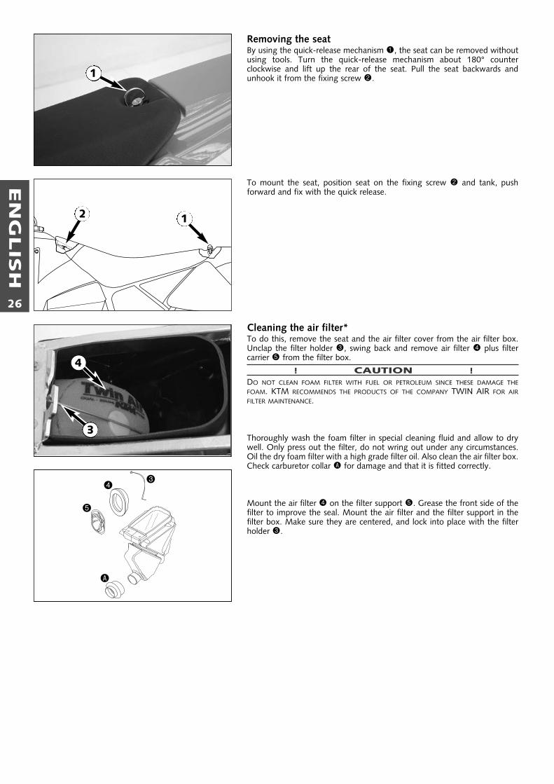
Removing the seatBy using the quick-release mechanism 1, the seat can be removed withoutusing tools. Turn the quick-release mechanism about 180° counter clockwise and lift up the rear of the seat. Pull the seat backwards andunhook it from the fixing screw 2.
To mount the seat, position seat on the fixing screw 2 and tank, push forward and fix with the quick release.
Cleaning the air filter*To do this, remove the seat and the air filter cover from the air filter box.Unclap the filter holder 3, swing back and remove air filter 4 plus filter carrier 5 from the filter box.
! CAUTION !DO NOT CLEAN FOAM FILTER WITH FUEL OR PETROLEUM SINCE THESE DAMAGE THEFOAM. KTM RECOMMENDS THE PRODUCTS OF THE COMPANY TWIN AIR FOR AIRFILTER MAINTENANCE.
Thoroughly wash the foam filter in special cleaning fluid and allow to drywell. Only press out the filter, do not wring out under any circumstances.Oil the dry foam filter with a high grade filter oil. Also clean the air filter box.Check carburetor collar A for damage and that it is fitted correctly.
Mount the air filter 4 on the filter support 5. Grease the front side of thefilter to improve the seal. Mount the air filter and the filter support in the filter box. Make sure they are centered, and lock into place with the filterholder 3.
34
5
A
4
3
1
12

EN
GLIS
H
27
Exhaust systemThe silencer is filled with glass-fiber yarn for damping. When in use, theglass-fiber yarn becomes loose or coked with oil carbon. This can lead to apower loss and a reduction of the silencer damping. The glass-fiber yarnpacking can be replaced in a few easy steps.To replace, remove the silencer from the vehicle and mark the position ofthe outer tube 1 to the inner tube 2. Remove screws 3 and the end cap4. Pull of the outer tube and remove the old glass-fiber yarn packing 5from the inner tube. Thoroughly clean all parts.
To assemble, mount a new glass-fiber yarn packing onto the inner tube (seeillustration) and slide into the outer tube. Mount end cap and fix withscrews 1. Before tightening the screws, turn the outer tube until theymatch the positions you marked. Mount the silencer and check the exhaustsystem for tightness.
NOTE: Glass fiber yarn packages are offered by your licensed KTM dealer.
� WARNING �THE EXHAUST SYSTEM BECOMES VERY HOT WHILE THE MOTORCYCLE IS RUNNING. TOAVOID BURNS DO NOT START WORK ON THE EXHAUST SYSTEM UNTIL IT HAS PROPERLYCOOLED DOWN.
Checking the oil level of the hydraulic clutch To check the oil level in the master cylinder of the clutch remove thecover. For this purpose, remove screws 6 and cover 7 together withthe rubber boot 8. The oil level in the horizontal-positioned mastercylinder should be 4 mm below the upper edge. If necessary, fill up with biodegradable hydraulic oil SAE 10 (e.g. ShellNaturelle HF-E15).Biodegradable hydraulic oil is available from yourKTM dealer (50ml).
! CAUTION !KTM USES BIODEGRADABLE HYDRAULIC OIL FOR THE HYDRAULIC CLUTCH CONTROL.NEVER MIX BIODEGRADABLE HYDRAULIC OILS WITH MINERAL OILS.ALWAYS USE BIODEGRADABLE HYDRAULIC OIL SAE 10 (e.g. Shell Naturelle HF-E15) TO FILL UP THE MASTER CYLINDER. NEVER REFILL WITH MINERAL HYDRAULICOIL OR BRAKE FLUID.
Bleeding of the hydraulic clutchTo bleed, the cover of the master cylinder of the clutch needs to be removed. For this purpose, remove screws 6 and take off the cover7together with the rubber bellows 8. At the slave cylinder of the clutch,remove the bleeder nipple bk. In its place, mount the bleeder syringe 9which is filled with SAE 10 hydraulic oil. Refill oil, until oil is discharged fromthe bore bl of the master cylinder in a bubble-free state. Make sure that theoil does not overflow. The bleeder syringe can be purchased from your KTMdealer.Having completed the bleeding procedure, you have to verify thatthe oil level in the master cylinder is correct.If necessary, fill up with biodegradable hydraulic oil SAE 10 (e.g. Shell Naturelle HF-15).Biodegradable hydraulic oil is available from your KTM dealer (50ml).
! CAUTION !KTM USES BIODEGRADABLE HYDRAULIC OIL FOR THE HYDRAULIC CLUTCH CONTROL.NEVER MIX BIODEGRADABLE HYDRAULIC OILS WITH MINERAL OILS.ALWAYS USE BIODEGRADABLE HYDRAULIC OIL SAE 10 (e.g. Shell Naturelle HF-E15)TO FILL UP THE MASTER CYLINDER. NEVER REFILL WITH MINERAL HYDRAULIC OIL ORBRAKE FLUID.
3
5
4
2
1
67
8
11
10
9

EN
GLIS
H
28
Changing the original position of the clutch leverThe adjusting screw 1 can be used for individual adjustment of the originalposition of the clutch lever, thus allowing adjustment to an optimal positionfor every hand size.Turning the adjusting screw clockwise reduces the distance between theclutch lever and the handlebar. Turning the adjusting screw counterclock-wise increases the distance between the clutch lever and the handlebar.
! CAUTION !ADJUSTMENT OF THE CLUTCH LEVER POSITION IS ONLY POSSIBLE WITHIN CERTAIN LIMITS.ONLY TURN THE ADJUSTING SCREW MANUALLY AND NEVER APPLY EXCESSIVE FORCE.
Cooling systemThe water pump 2 in the engine keeps the cooling liquid in circulation. The cooling liquid is cooled by the air stream. Therefore, the cooling effectis reduced when the traveling speed is reduced. Dirty radiators additionallyreduce the cooling effect.
The cooling liquid can be drained by removing the screw 3 on the water-pump cover.
� WARNING �DO NOT REMOVE ANY COOLER HOSES OR THE DRAIN SCREW WHEN THE ENGINE IS HOT.
A mixture of 40% antifreeze liquid and 60% water is used as coolant. However, the antifreeze protection must be at least -25° C (-13° F). Thismixture offers antifreeze protection but also good corrosion protection andshould therefore not be replaced by pure water.
! CAUTION !FOR THE COOLING SYSTEM, USE ONLY WITH HIGH-GRADE ANTIFREEZE (SHELL ADVANCECOOLANT). USING LOWER-GRADE ANTIFREEZE AGENTS CAN CAUSE CORROSION ANDCOOLANT FOAMING.
Pressure induced by heating of the coolant in the system is controlled by avalve in the radiator cap 4; a water temperature rising up to 120° C (248° F)is admissible, without fear of problems.
Checking coolant levelThe coolant should be 10 mm (0.4 in) above the radiator fins when theengine is cold (see illustr.). In the event of the coolant being drained, alwaysfill and bleed the system.
� WARNING �IF POSSIBLE, ALWAYS CHECK THE LEVEL OF THE COOLING LIQUID WHEN THE ENGINE ISCOLD. IF YOU HAVE TO OPEN THE RADIATOR CAP WHEN THE ENGINE IS HOT, USE A RAGTO COVER THE CAP AND OPEN SLOWLY TO RELEASE PRESSURE.
Adjusting the throttle cable*There must always be a 3-5 mm (0.1-0.2 in) play in the throttle cable. Tocheck this, move back the protective cover 5 on the throttle grip. You mustbe able to lift the outer covering of the cable 3-5 mm from the adjustingscrew 6 until resistance is felt.To adjust, loosen the counternut 7 and turn the adjusting screw accordingly. Finally tighten the counternut and slide the protective coverback on.
To check the correctness of this setting, start the engine, turn the handlebar left and right, in both cases as far as it will go. This must not causeany changes in idling speed. Otherwise, you will have to increase the backlash of the throttle cable.
when engine is cold
10 mm
3-5 mm
5 6
1
4
7
2
3

EN
GLIS
H
29
Carburetor adjustment *Basic information on the original carburetor settingThe original carburetor setting was adapted for an altitude of approx. 500 meters (1600 ft.) above sea level, and the ambient temperature of approx. 20° C (68° F), mainly for off-road use and central European premium-grade fuel (ROZ 95). Mixing ratio 2-stroke motor oil : super fuel 1:40 .Basic information of changing the carburetor settingAlways start out from the original carburetor setting. Essential requirements are a clean air filter system, air-tight exhaust system andan intact carburetor. Experience has shown that adjusting the main jet, the idling jet and the jet needle is sufficient and that changesto other parts of the carburetor will not greatly affect engine performance.RULE OF THUMB: high altitude or high temperatures ➞ choose leaner carburetor adjustment
low altitude or low temperatures ➞ choose richer carburetor adjustment
� WARNING �– ONLY USE PREMIUM-GRADE GASOLINE ROZ 95 MIXED WITH HIGH-GRADE TWO-STROKE ENGINE OIL. OTHER TYPES OF GASOLINE CAN CAUSE ENGINE
FAILURE, AND THEIR USE WILL VOID YOUR WARRANTY.– ONLY USE HIGH-GRADE 2-STROKE ENGINE OIL OF KNOWN BRANDS (I. E. SHELL ADVANCE RACING X).– NOT ENOUGH OIL OR LOW-GRADE OIL CAN CAUSE EROSION OF THE PISTON. IF YOU USE TOO MUCH OIL, THE ENGINE CAN START SMOKING AND FOUL
THE SPARK PLUG.– IN THE CASE OF A LEANER ADJUSTMENT OF THE CARBURETOR PROCEED CAUTIOUSLY. ALWAYS REDUCE THE JET SIZE IN STEPS OF ONE NUMBER TO AVOID
OVERHEATING AND PISTON SEIZURE.
NOTE: If the engine does not run properly, despite a changed adjustment look for mechanical faults and check the ignition system.
Basic information on carburetor wearAs a result of engine vibrations, the throttle valve, jet needle, and needle jet are subjected to increased wear. This wear may cause carburetor malfunction (e.g. overly rich mixture). Therefore, these parts should be replaced after 1000 hours of using.
Idling range – A, Adjusting the idle speedOperation with closed throttle valve. This range is influenced by the idleadjusting screw 1. Only make adjustments when the engine is hot.The idling speed can be changed by turning the idle adjusting screw.Turning it clockwise produces a higher idling speed and turning the screwcounterclockwise produces a lower idling speed.
Opening up – BEngine behavior when the throttle opens. The idle jet and the shape of thethrottle valve influences this range. If, despite good idling-speed and part-throttle setting, the engine sputters and smokes when the throttle isfully opened and develops its full power not smoothly but suddenly at high engine speeds, the mixture to the carburetor will be too rich, the fuel leveltoo high or the float needle is leaking.
Part-throttle range – COperation with partly open throttle valve. This range is only influenced bythe jet needle (shape and position). The optimum part-throttle setting is controlled by the idling setting in the lower range and by the main jet in theupper range. If the engine runs on a four-stroke cycle or with reduced powerwhen it is accelerated with the throttle partly open, the jet needle must belowered by one notch. If the engine pings, especially when acceleratingunder full power at maximum engine revs, the jet needle should be raised.If these faults should occur at the lower end of the part throttle range at afour-stroke running, make the idling range leaner; if the engine pings, adjustthe idling range richer.
Full throttle range – DOperation with the throttle fully open (flat out). This range is influenced bythe main jet and the jet needle. If the porcelain of the new spark plug isfound to have a very bright or white coating or if the engine rings, after ashort distance of riding flat out, a larger main jet is required. If the porcelainis dark brown or black with soot the main jet must be replaced by a smallerone.
B
C
D
A
main jetjet needle
jet needle
idling jet
idling jetthrottle valve
1

EN
GLIS
H
30
Draining the float chamber of the carburetorFollowing every wet-cleaning procedure, the float chamber of the carburetor should be drained in order to remove any water that may havepenetrated into it. Water in the float chamber leads to engine malfunction.Make sure you do this while the engine is cold. Close the fuel tap and placea cloth under the carburetor which is capable of absorbing the leaking fuel.Unscrew the plug 1 and clean it with compressed air. Then, mount the plugtogether with the gasket, open fuel tap, and check the float chamber forleaks.
� WARNING �FUEL IS EASILY FLAMMABLE AND TOXIC. WHEN HANDLING FUEL, BE SURE TO EXERCISETHE UTMOST CAUTION. NEVER PERFORM ANY WORK ON THE FUEL SYSTEM NEAR OFOPEN FLAMES OR BURNING CIGARETTES. ALWAYS ALLOW THE ENGINE TO COOL OFFFIRST. IMMEDIATELY CLEAN UP ANY FUEL WHICH MAY HAVE BEEN SPILLED. MATERIALSSATURATED WITH FUEL ARE ALSO EASILY FLAMMABLE. IN CASE YOU INGESTED FUEL ORFUEL SPLASHED INTO YOUR EYES, CONSULT A DOCTOR IMMEDIATELY.DISPOSE OF THE FUEL PROPERLY!
Checking gear oil levelAn inspection glass 2 on the left side of the engine allows easy checking ofthe gear oil level.Warm up the engine, then turn it off and wait two minutes until the oil hasflown back into the gearbox case.Park the motorcycle straight on a horizontal surface and check the oil level.The oil level must not drop below the "MIN" mark of the inspection glass.Note: If the motorcycle is not parked properly for the oil level inspection itwill not be possible to achieve a reliable result.If necessary add gear oil 20W30 (e.g. Shell Advance Ultra 4).
! CAUTION !NOT ENOUGH OIL OR A POOR OIL QUALITY LEAD TO PREMATURE WEAR OF THETRANSMISSION. THEREFORE, USE ONLY HIGH-QUALITY OILS (E.G. SHELL ADVANCE ULTRA 4).
Changing gear oil *Before changing the gear oil warm up the engine and park the motorcycleon a horizontal surface. Remove the oil drain plug 3 and drain the used oilinto an appropriate container. Clean the sealing surface. Mount the oil drainplug together with its gasket and tighten to 15 Nm.
Remove the filler plug 4 and add 0.30 l gear oil 20W30 (e.g. Shell AdvanceUltra 4). Mount the filler plug and check the engine for leaks.
! CAUTION !NOT ENOUGH OIL OR A POOR OIL QUALITY LEAD TO PREMATURE WEAR OF THETRANSMISSION. THEREFORE, USE ONLY HIGH-QUALITY OILS (E.G. SHELL ADVANCE ULTRA 4).
2
1
3
4

EN
GLIS
H
31
CAUSE
Operating error
Fuel supply interrupted
Electrode distance too great
Plug fouled by oil, wet or bridged
Ignition wire or spark plug connec-tor damaged
Kill button wire or short-circuit switch faulty
Loose ignition cable connectors
Spark too weak
Water in the carburetor and jetsblocked
Idle adjusting screw out of adjustment
Ignition system damaged
Wear
Charred glass fiber yarn in silencer
Air filter obstructed
Fuel supply partly interrupted orblocked
Loss of compression through loosespark plug
Exhaust system damaged
Engine has not enough preignition
REMEDY
Open fuel tap, replenish fuel, do not use choke
Close fuel tap, loosen fuel hose at carburettor, lead into abasin and open fuel tap,– if fuel leaks out, clean carburettor– if no fuel leaks out, check tank ventilation, i.e. clean fuel tap
Reduce electrode distance (0.60 mm)
Clean spark plug or renew
Dismount spark plug, connect ignition cable, hold to ground(blank place on engine) and actuate kickstarter, a strong sparkmust be produced at the spark plug– If no spark is produced, loosen spark plug cap from ignition
cable, hold about 5 mm from ground and actuate kickstarter– If a spark now occurs, replace spark plug cap– If no spark is produced, control ignition system
Disconnect black coloured cable from short circuit button atignition coil and check ignition spark. If the spark is O.K. repairdefective part of cable or ignition switch
Inspect cable connectors
Examine ignition system
Dismantle and clean carburetor
Readjust idle running or replace idle adjusting screw
Examine ignition system
Overhaul engine
Renew filling
Clean or renew airfilter
Blow through fuel pipe and clean carburetor
Tighten spark plug
Check exhaust system for damage
Check and adjust ignition
TROUBLE
Engine fails to start
Engine without idle running
Engine has not enoughpower
TROUBLE SHOOTING
If you let the specified maintenance work on your motorcycle be carried out, disturbances can hardly be expected. Should an error occurnevertheless, we advise you to use the trouble shooting chart in order to find the cause of error.We would like to point out that many operations cannot be performed by oneself. In case of uncertainty, please contact a KTM-dealer.

EN
GLIS
H
32
TROUBLE
Engine has not enoughpower
Engine revs not up andrunning in four strokecycle
High rpm misfiring
Engine spluters into thecarburetor
Engine overheating
Emission of white smoke(steam)
Excessive oil escapes fromtransmission breather tube
Water in transmission oil
CAUSE
Reed paddles tensionless or damaged,surface of reed valve housing damaged
Wear
Carburetor overflows if level adjusttoo high, float needle seating isdirty or enlarged
Loose carburetor jets
Incorrect heat range spark plug or low quality spark plug
Loose, corroded or non conductiveignition socket connector
Lack of fuel
Spark plug with incorrect heat value(Ignition by incandescence)
Engine takes air out of control
Insufficient liquid in cooling system
Radiator fins clogged
Frothing in cooling system
Pinched or kinked water hoses
Incorrect ignition timing because ofloose stator screws
Incorrect compression ratio
Cylinder head or O-ring of cylinderhead gasket leaks
Excessive oil quantity in transmissi-on
Shaft seal ring of the water pumpdefect
REMEDY
Replace reed paddles or reed valve housing
Overhaul engine
Clean carburetor, if necessary replace float needle and adjustlevel
Tighten jets
Refer to technical data section
Check and seal with silicon
Clean fuel pipes, examine tank aeration and clean
Fit correct spark plug
Check intake flange and carburettor if firmly setted
Top up coolant and bleed cooling system check coolingsystem for leaks
Clean radiatar fins with water jet
Renew coolant using branded anti-freeze/anti-corrosive (ShellAdvance Coolant)
Replace with correct routed hoses
Readjust to correct ignition timing specifications, secure scr-ews with Loctite 243
Measure and adjust compression ratio
Check cylinder head, replace O-ring
Correct transmission oil level
Replace shaft seal ring of the water pump.

EN
GLIS
H
33
Clean your motorcycle regularly in order to keep its painted finish looking shiny and new.The best manner would be to use warm water that has been mixed with a commercially available washing detergent and a sponge.The hard dirt can be removed before with the help of a soft water jet.
! CAUTION !NEVER CLEAN YOUR MOTORCYCLE WITH A HIGH-PRESSURED CLEANER OR A HIGH-PRESSURED WATER JET. OTHERWISE THE WATER MIGHT RUN INTO THEELECTRICAL COMPONENTS, CONNECTORS, SHEATHED CABLES, BEARINGS, CARBURETOR ETC. AND CAUSE MAILFUNCTIONS, I.E., LEAD TO THE PREMATUREDESTRUCTION OF THESE PARTS.
– You should use commercially available detergents to clean the motorcycle. Heavily soiled parts should also be cleaned with the helpof a paint brush.
– Before cleaning with water, plug the exhaust pipe to prevent water ingress.– After the motorcycle has been rinsed with a soft water jet, it should be dried by air pressure and a cloth. Then take a short drive until
the engine has reached its operating temperature, and also operate the brakes. The heat also causes the water at the inaccessibleparts of the engine and the brakes to evaporate.
– Slide back the protective covers on the handlebar-mounted instruments so that any water that may have seeped into this part of themotorcycle is allowed to evaporate.
– After the motorcycle has cooled down, oil and grease all the gliding bearing parts. Also treat the chain with a chain spray.– To prevent failures in the electric system, you should treat the short circuit button with a contact spray.
If you want to put your motorcycle away for longer periods of time, please observe the following instructions:
– Clean motorcycle thoroughly (see chapter: CLEANING)– Change engine oil (old engine oil contains aggressive contaminations).– Check antifreeze and amount of cooling liquid.– Let the engine warm up again, close fuel tap and wait until the engine dies off by itself. In this way, the carburetor jets are
prevented from becoming resin-clogged by the old fuel.– Remove spark plug and fill in approx. 5 ccm of engine oil into the cylinder through the opening. Actuate kickstarter 10 times in order
to distribute the oil onto the cylinder walls and mount the spark plug.– Let fuel flow out of tank into an appropriate basin.– Correct tire pressure.– Lubricate bearing points of the control levers, footrests, etc. as well as the chain.– The storage place should be dry and not be subjected to overly great temperature fluctuations.– Cover the motorcycle with an air permeable tarpaulin or blanket. Do not use airtight materials, as possible humidity might not be
able to escape and thereby cause corrosion.
� WARNING �IT WOULD BE VERY BAD TO LET THE ENGINE RUN FOR A SHORT TIME DURING THE STORAGE PERIOD. THE ENGINE WOULD NOT GET WARMED UP ENOUGH ANDTHE THUS DEVELOPED STEAM WOULD CONDENSE DURING THE COMBUSTION PROCESS AND CAUSE THE EXHAUST TO RUST.
USE AFTER PERIOD OF STORAGE– Fill up tank with fresh fuel.– Check motorcycle as before each start (see driving instructions).– Take a short, careful test ride first.
NOTE: Before you put your motorcycle away for the winter, you should check all parts for their function and wear. Should any service jobs, repairs, or any refitting be necessary, you should have them carried out during the off-season (lower workload at mechanics' shops). This way, you can avoid the long waiting times at your shop at the beginning of the next biking season.
CLEANING
STORAGE

EN
GLIS
H
34
Spring 3,14 N/mm
Preload bushing - length 10 mm
Oil capacity per fork leg 210 ccm
Fork oil SAE 7.5
STANDARD ADJUSTMENT – FORK
WP 0318X713
Compression adjuster 3
Rebound adjuster 6
Spring 40-220
Spring preload 7mm (0.3 in)
STANDARD ADJUSTMENT - SHOCK ABSORBER
Frame Central chrome-moly-steel frame
Fork telescopic fork (Marzocchi USD Ø 35)
Wheel travel front/rear 220 mm (8.7 in) / 270 mm (10.7 in)
Rear suspension central shock absorber (White Power)
Front brake Disc brake Ø 200 mm (7.9 in), 1 piston
Rear brake Disc brake Ø 160 mm (6.3 in), 1 piston
Tires front: 60/100-14“ rear: 80/100-12“
Air pressure front / rear: 1.0 bar (14 psi) / 1.0 bar (14 psi)
Fuel tank capacity 3.4 liter (0.92 USgal)
Final drive ratio 14 : 50 t
Chain 1/2 x 1/4" (415) 108 rolls
Steering angle 63.8 °
Wheel base 1137 mm (44.7 in)
Seat height, unloaded 750 mm (30 in)
Ground clearance 290 mm (11.5 in)
Dead weight without fuel 55 kg (121.4 lbs)
Rider’s body height max. 160 cm (63 in)
Rider’s body weight max 50 kg (22.7 lbs)
Recommended age of rider 8 to 12 years
Engine CR65
TECHNICAL SPECIFICATIONS – CHASSIS 65 SX 2003
Hexagon screw - brake caliper M 8 Loctite 243 + 20 Nm
Flat head screw - brake discs M6 Loctite 243 + 10 Nm
Hexagon nut - front wheel spindle M 10 30 Nm
Hexagon nut - rear wheel spindle M 12x1 50 Nm
Hexagon nut - swingarm bolt M 12x1 40 Nm
Clamping screws - upper fork bridge M 8 20 Nm
Clamping screws - lower fork bridge M 8 15 Nm
AH screw - handlebar clamp M 8 20 Nm
Spoke nipple M 3,5 3-4 Nm
Other chassis screws M 5 6 Nm
M 6 10 Nm
M 8 25 Nm
M 10 40 Nm
TIGHTENING TORQUES

EN
GLIS
H
35
Engine CR-65
Design Liquid cooled single cylinder two-stroke engine with reed valve intake
Displacement 64,85 ccm
Bore/stroke 45 / 40,8 mm (1.77/1.6 in)
Compression ratio 9.1 : 1
Fuel SUPER fuel, research octane no 95, mixed with high grade two-stroke oil
Oil/gasoline ratio 1 : 40 when using high grade two-stroke oil (e.g. Shell Advance Racing X), when in doubt, please contact our importer
Lubrication mixture lubrication
Crankshaft bearing 2 deep-groove ball bearing
Connecting rod bearing needle bearing
Piston pin bearing needle bearing
Piston rings 1 compression ring
Primary drive straight cut spur gears, 23:75 t
Clutch multiple disc clutch in oil bath, hydraulic operated (Shell HF-E15)
Transmission 6 speed, claw actuated
Gear ratio 1st gear 13 : 372nd gear 16 : 343rd gear 18 : 314th gear 21 : 305th gear 23 : 286th gear 24 : 26
Transmission oil 0.30 liter (0.0792 USgal) gear oil 20W30 (e.g. Shell Advance Ultra 4)
Ignition system Moric Digital 2M1
Spark plug NGK BR 8 ECM
Electrode gap 0.60 mm (0.0236 in)
Carburetor Mikuni VM 24
Coolant 0.55 liter (0.145 Usgal), mixture coolant : water = 2 : 1, at least -25° C (-13° F)
Air filter wet foam type air filter insert
TECHNICAL SPECIFICATIONS - ENGINE 65 SX 2003
Carburetor Mikuni VM 24
Main jet 200
Needle jet N-8
Idling jet 30
Jet needle 5114-3
Needle position from top III
Throttle valve 2.0
Starting jet 20
BASIC CARBURETOR SETTING
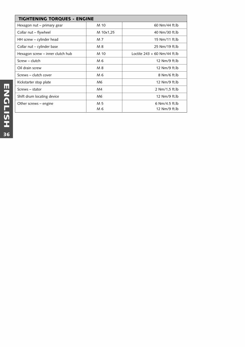
EN
GLIS
H
36
Hexagon nut – primary gear M 10 60 Nm/44 ft.lb
Collar nut – flywheel M 10x1,25 40 Nm/30 ft.lb
HH screw – cylinder head M 7 15 Nm/11 ft.lb
Collar nut – cylinder base M 8 25 Nm/19 ft.lb
Hexagon screw – inner clutch hub M 10 Loctite 243 + 60 Nm/44 ft.lb
Screw – clutch M 6 12 Nm/9 ft.lb
Oil drain screw M 8 12 Nm/9 ft.lb
Screws – clutch cover M 6 8 Nm/6 ft.lb
Kickstarter stop plate M6 12 Nm/9 ft.lb
Screws – stator M4 2 Nm/1,5 ft.lb
Shift drum locating device M6 12 Nm/9 ft.lb
Other screws – engine M 5 6 Nm/4.5 ft.lbM 6 12 Nm/9 ft.lb
TIGHTENING TORQUES - ENGINE

EN
GLIS
H
37
Page
Adjusting of free travel at the hand brake lever..................20
Adjusting the throttle cable ................................................28
Basic suspension setup for the weight of the driver ............17
Bleeding of the hydraulic clutch..........................................27
Braking ...............................................................................13
Breather plug front fork......................................................18
Carburetor adjustment........................................................29
Chain maintenance.............................................................19
Changing the basic position of the brake pedal ..................22
Changing the gear oil .........................................................30
Changing the original position of the clutch lever...............28
Changing the spring preloading of the shock absorber.......19
Chassis number ....................................................................6
Check the rear brake fluid level ..........................................23
Checking and adjusting the steering head bearing..............16
Checking of brake fluid level - front brake .........................21
Checking the chain tension.................................................19
Checking the coolant level..................................................28
Checking the front brake pads............................................21
Checking the gear oil level..................................................30
Checking the oil level of the hydraulic clutch......................27
Checking the rear brake pads .............................................23
Checking the spoke tension................................................25
Choke...................................................................................7
Cleaning .............................................................................33
Cleaning the air filter ..........................................................26
Cleaning the dust scrabbers of the telescopic fork ..............18
Clutch lever ..........................................................................6
Compression damping of shock absorber .............................8
Cooling system ...................................................................28
Correcting the chain tension...............................................19
Draining the float chamber of the carburetor .....................30
Driving instructions.............................................................11
Engine number .....................................................................6
Exhaust system ...................................................................27
Filler cap ...............................................................................7
Foot brake pedal...................................................................8
Fuel tap ................................................................................7
Page
General information about KTM disc brakes.......................20
General tips and warnings for starting the motorcYcle .......10
Hand brake lever ..................................................................6
How to change the handlebar position...............................18
INDEX.................................................................................37
Instructions for the first ride................................................10
Kickstarter.............................................................................8
Maintenance work on chassis and engine...........................16
Operation instruments..........................................................6
Periodic maintenance schedule ...........................................14
Plugin-Stand.........................................................................8
Rebound damping function of the shock absorber ...............8
Refilling the front brake fluid reservoir................................21
Refilling the rear brake fluid reservoir .................................23
Refueling, fuel ....................................................................13
Removing and installing the front wheel ............................24
Removing and installing the rear wheel ..............................25
Removing the seat..............................................................26
Replacing the front brake pads ...........................................22
Replacing the rear brake pads.............................................23
Running in..........................................................................10
Serial number locations.........................................................6
Shift lever .............................................................................7
Shifting, Riding ...................................................................12
Short circuit button...............................................................6
Starting off .........................................................................12
Starting when engine is cold...............................................12
Starting when engine is warm ............................................12
Stopping.............................................................................13
Storage ...............................................................................33
Technical data - chassis ......................................................34
Technical data - engine ......................................................35
Tires, air pressure................................................................25
To determine the sag of the shock absorber.......................17
To determine the sag of the telescopic fork........................17
Trouble shooting ................................................................31
What to do when the engine is “flooded“ .........................12
What you should check before each start...........................11
INDEX

EN
GLIS
H
38

KTM
SP
OR
TM
OTO
RC
YC
LE
AG
5230
Mat
tigho
fen
Aus
tria
Inte
rnet
: ww
w.k
tm.a
t
321047