sx-40 sx-50 photovoltaic modules - trichord inc · 2005-02-09 · sx-40 sx-50 photovoltaic modules...
TRANSCRIPT

630 Solarex Court Frederick
Maryland 21703 www.solarex.com
Phone: (301) 698-4200Fax: (301) 698-4201
© Solarex 1999
Specifications subject to change without notice
6047-1 4/99
SX-40 SX-50
Photovoltaic Modules
Typical commercial applications of these modules,which generate peak power of 40 watts and 50 wattsrespectively, include remote telemetry, instrumenta-tion systems, security sensors, and land-basednavigation aids. They are also well-suited to provid-ing subsistence power to homes in remote areaswithout utility (mains) service. They are available inthree configurations: the M configuration, which in-cludes the versatile MultiMount™ frame and a15-foot output cable; the D configuration, whichmounts directly to many surfaces without additionalhardware; and the U configuration, which includesthe heavy-duty Universal frame and a high-volumejunction box with dual-voltage output.
The SX-40M and SX-50MThe SX-40M and -50M are general-purpose PV mod-ules suitable for applications compatible with theMultiMount™ frame and the modules’ electrical characteristics. They are for use in single-module applications with DC system voltage not exceeding30 volts.
MultiMount™ FrameThe MultiMount™ frame of the SX-40M and -50Mprovides tremendous flexibility in mounting approach.Oriented parallel to the edge and back of the module,its dual channels accept the heads of 5⁄16" or 8mmhex bolts, allowing the module to be mounted fromthe side or back. Bolts may be located anywherealong the channels (shown at left with end capsremoved), a configuration which prevents them fromturning during tightening and allows installation withjust one wrench.
Complete, Factory-WiredOutput of the M configuration is via a 15-foot (4.6m)PVC-jacketed AWG 14-2 cable which terminates ina low-profile junction box on the module back.Epoxy-potted in the box, module electrical connec-tions are sealed against corrosion and effectivelystrain-relieved. Output voltage is compatible with12VDC systems.
SX-40 and SX-50 photovoltaic modules are part of Solarex’snew SX™ module series, providing cost-effective photovoltaicpower for DC loads with many energy requirements. With 36 polycrystalline cells in series, they charge batteries effi-ciently in virtually any climate. Their materials, design andconstruction reflect Solarex’s quarter-century of experience.
SX-50U
The Natural Source for Electricity™Solarex SX-40 and SX-50 modules are ideallysuited for modest power requirements in remoteareas such as this home lighting system in Nepal.
Top: DirectMount™ frame.
Center: MultiMount™ frame.
Bottom: Universal frame.
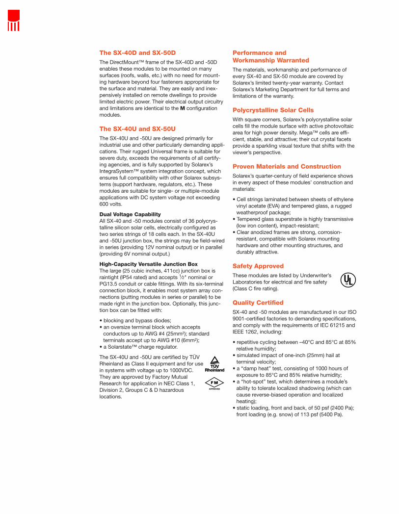
The SX-40D and SX-50DThe DirectMount™ frame of the SX-40D and -50Denables these modules to be mounted on many surfaces (roofs, walls, etc.) with no need for mount-ing hardware beyond four fasteners appropriate forthe surface and material. They are easily and inex-pensively installed on remote dwellings to providelimited electric power. Their electrical output circuitryand limitations are identical to the M configurationmodules.
The SX-40U and SX-50UThe SX-40U and -50U are designed primarily for industrial use and other particularly demanding appli-cations. Their rugged Universal frame is suitable forsevere duty, exceeds the requirements of all certify-ing agencies, and is fully supported by Solarex’sIntegraSystem™ system integration concept, whichensures full compatibility with other Solarex subsys-tems (support hardware, regulators, etc.). Thesemodules are suitable for single- or multiple-moduleapplications with DC system voltage not exceeding 600 volts.
Dual Voltage CapabilityAll SX-40 and -50 modules consist of 36 polycrys-talline silicon solar cells, electrically configured astwo series strings of 18 cells each. In the SX-40Uand -50U junction box, the strings may be field-wiredin series (providing 12V nominal output) or in parallel(providing 6V nominal output.)
High-Capacity Versatile Junction BoxThe large (25 cubic inches, 411cc) junction box israintight (IP54 rated) and accepts 1⁄2" nominal orPG13.5 conduit or cable fittings. With its six-terminalconnection block, it enables most system array con-nections (putting modules in series or parallel) to bemade right in the junction box. Optionally, this junc-tion box can be fitted with:
• blocking and bypass diodes;• an oversize terminal block which accepts
conductors up to AWG #4 (25mm2); standardterminals accept up to AWG #10 (6mm2);
• a Solarstate™ charge regulator.
The SX-40U and -50U are certified by TÜVRheinland as Class II equipment and for usein systems with voltage up to 1000VDC.They are approved by Factory MutualResearch for application in NEC Class 1,Division 2, Groups C & D hazardous locations.
Performance and Workmanship WarrantedThe materials, workmanship and performance ofevery SX-40 and SX-50 module are covered bySolarex’s limited twenty-year warranty. ContactSolarex’s Marketing Department for full terms andlimitations of the warranty.
Polycrystalline Solar CellsWith square corners, Solarex’s polycrystalline solarcells fill the module surface with active photovoltaicarea for high power density. Mega™ cells are effi-cient, stable, and attractive; their cut crystal facetsprovide a sparkling visual texture that shifts with theviewer’s perspective.
Proven Materials and ConstructionSolarex’s quarter-century of field experience showsin every aspect of these modules’ construction andmaterials:
• Cell strings laminated between sheets of ethylenevinyl acetate (EVA) and tempered glass, a ruggedweatherproof package;
• Tempered glass superstrate is highly transmissive(low iron content), impact-resistant;
• Clear anodized frames are strong, corrosion-resistant, compatible with Solarex mountinghardware and other mounting structures, anddurably attractive.
Safety ApprovedThese modules are listed by Underwriter’sLaboratories for electrical and fire safety(Class C fire rating).
Quality CertifiedSX-40 and -50 modules are manufactured in our ISO9001-certified factories to demanding specifications,and comply with the requirements of IEC 61215 andIEEE 1262, including:
• repetitive cycling between –40°C and 85°C at 85%relative humidity;
• simulated impact of one-inch (25mm) hail atterminal velocity;
• a “damp heat” test, consisting of 1000 hours ofexposure to 85°C and 85% relative humidity;
• a “hot-spot” test, which determines a module’sability to tolerate localized shadowing (which cancause reverse-biased operation and localizedheating);
• static loading, front and back, of 50 psf (2400 Pa);front loading (e.g. snow) of 113 psf (5400 Pa).

Typical Electrical Characteristics(1)
SX-40 SX-50Maximum power (Pmax) 40W 50WVoltage at Pmax (Vmp) 16.8V 16.8VCurrent at Pmax (Imp) 2.37A 2.97AGuaranteed minimum Pmax 36W 45WShort-circuit current (Isc) 2.58A 3.23AOpen-circuit voltage (Voc) 21.0V 21.0VTemperature coefficient
of Isc (0.065±0.015)%/°CTemperature coefficient
of Voc –(80±10)mV/°C Temperature coefficient
of power –(0.5±0.05)%/°C NOCT2 47±2°C
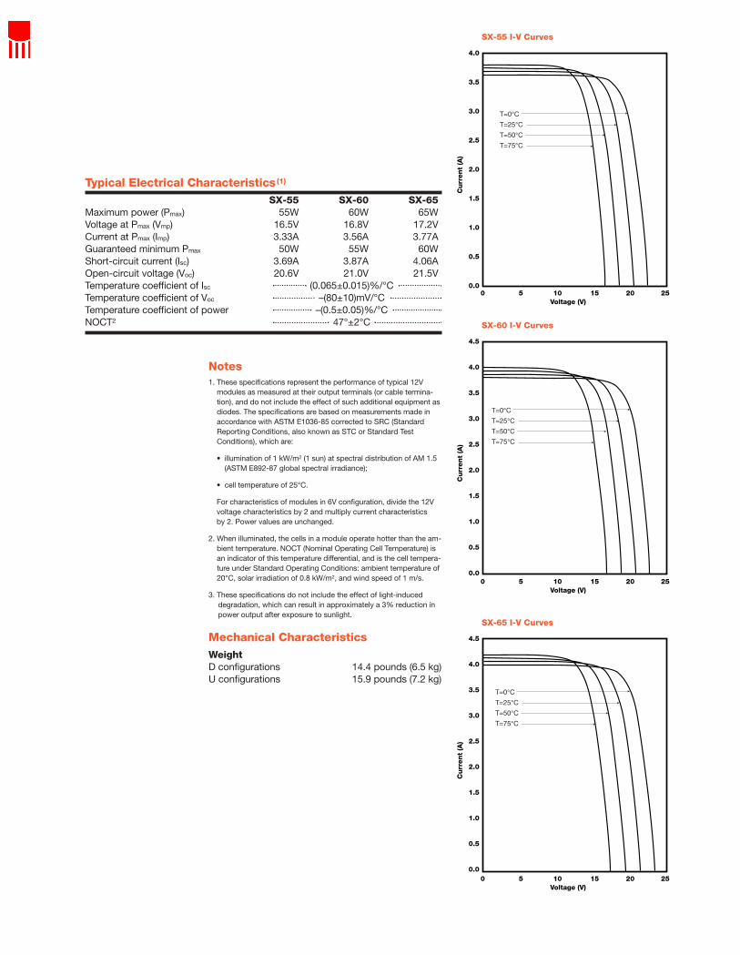
Notes1. These specifications represent the performance of typical 12V
modules as measured at their output terminals (or cable termina-tion), and do not include the effect of such additional equipment asdiodes. The specifications are based on measurements made inaccordance with ASTM E1036-85 corrected to SRC (StandardReporting Conditions, also known as STC or Standard TestConditions), which are:
• illumination of 1 kW/m2 (1 sun) at spectral distribution of AM 1.5(ASTM E892-87 global spectral irradiance);
• cell temperature of 25°C.
For characteristics of modules in 6V configuration, divide the 12Vvoltage characteristics by 2 and multiply current characteristics by 2. Power values are unchanged.
2. When illuminated, the cells in a module operate hotter than the am-bient temperature. NOCT (Nominal Operating Cell Temperature) isan indicator of this temperature differential, and is the cell tempera-ture under Standard Operating Conditions: ambient temperature of20°C, solar irradiation of 0.8 kW/m2, and wind speed of 1 m/s.
3. These specifications do not include the effect of light-induceddegradation, which can result in approximately a 3% reduction inpower output after exposure to sunlight.
Mechanical CharacteristicsWeightSX-40M, SX-40D 10.6 pounds (4.9 kg)SX-40U 11.8 pounds (5.4 kg)SX-50M, SX-50D 12.5 pounds (5.7 kg)SX-50U 13.9 pounds (6.3 kg)
3
2.5
2
1.5
1
0.5
0
Cu
rren
t (A
)
Voltage (V)0 5 10 15 20 25
SX-40 I-V Curves
T=0°CT=25°CT=50°CT=75°C
3.5
3.0
2.5
2.0
1.5
1.0
0.5
0.0
Cu
rren
t (A
)
Voltage (V)0 5 10 15 20 25
SX-50 I-V Curves
T=0°CT=25°CT=50°CT=75°C
30.20*
[767]
O* L* A B C
36.97*
[939]
36.77*
[934]
30.00*
[762]
SX–50U
SX–40U
0.69
[17]
7.00
[178]
6.39
[162]
15.00
[381]
24.00
[610]
0.100 [2.54] maxscrew head
projection, typ.
19.75 [502]
X X
O* C L*
Junction box
0.38 [9.6] dia.mtg. holes, typ.
0.69 [17] 18.37 [467]
A typ.
B
Grounding hole,2 places.
Front View
Back View
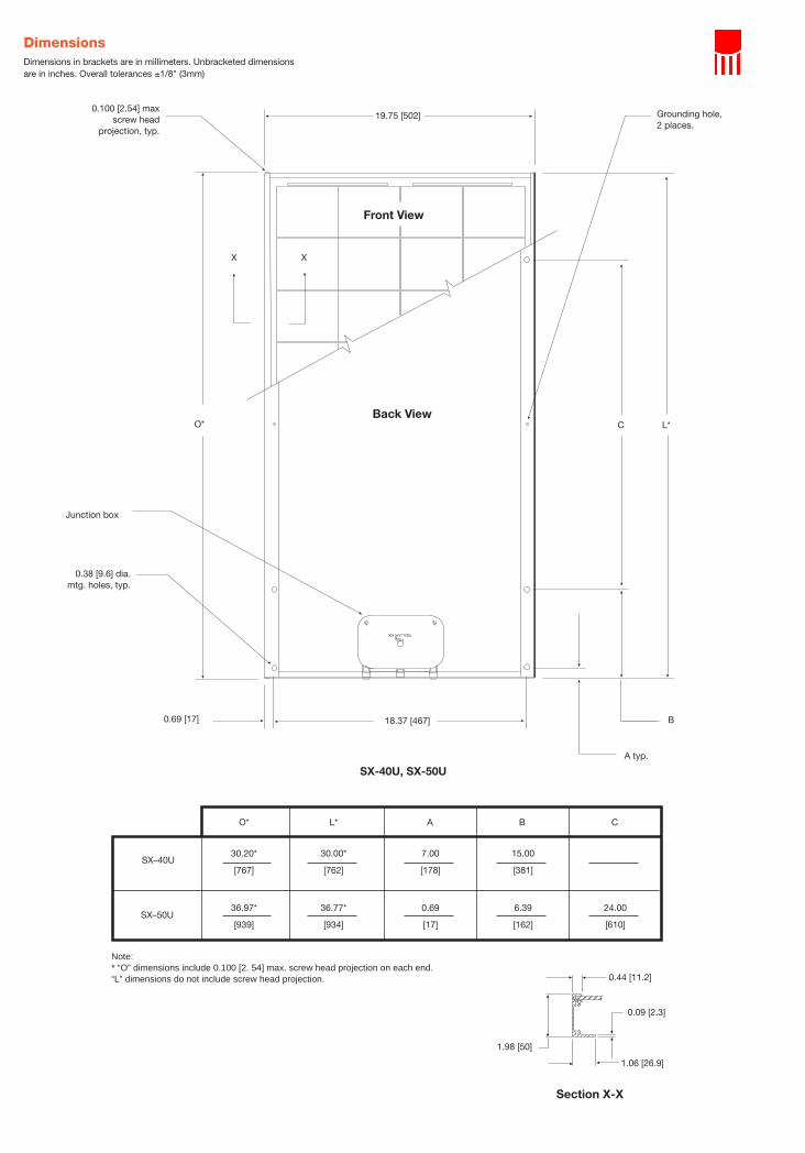
SX-40U, SX-50U
Note:* “O” dimensions include 0.100 [2. 54] max. screw head projection on each end. “L” dimensions do not include screw head projection. 0.44 [11.2]
0.09 [2.3]
1.06 [26.9]
1.98 [50]
Section X-X
DimensionsDimensions in brackets are in millimeters. Unbracketed dimensionsare in inches. Overall tolerances ±1/8" (3mm)

30.08*
[764]
O* L*
36.93*
[938]
36.73*
[933]
29.88*
[759]
SX–50M
SX–40M
19.72 [501]
Y Y
0.100 [2.54] maxscrew head
projection, typ.
Cable,15 feet lg.
Enclosure
0.67 [17] 18.38 [467]
O* L*Back View
Front View
SX-40M, SX-50M
Note:* “O” dimensions include 0.100 [2. 54] max. screw head projection on each end. “L” dimensions do not include screw head projection.
0.38 [9.7]
0.31 [7.9]0.33 [8.4]
0.67 [17]
0.33 [8.4]
0.31 [7.9]
0.89 [22.6]
0.30 [7.6]
Section Y-Y
DimensionsDimensions in brackets are inmillimeters. Unbracketeddimensions are in inches.Overall tolerances ±1/8" (3mm)

30.11*
[765]
O* L* A B C
36.95*
[938]
36.75*
[934]
29.91*
[760]
SX–50D
SX–40D
0.68
[17]
6.96
[177]
6.38
[162]
14.96
[380]
24.00
[610]
0.100 [2.54] maxscrew head
projection, typ.
Cable,15 feet lg.
Enclosure
0.38 [9.6] dia.mtg. holes, typ.
0.44 [11] 20.72 [526]
A typ
B
CO* L*
Grounding hole,2 places.
21.60 [549]
Z Z
Front View
Back View
SX-40D, SX-50D
Note:* “O” dimensions include 0.100 [2. 54] max. screw head projection on each end. “L” dimensions do not include screw head projection.
1.50 [38.1]
0.05 [1.3]
0.43 [10.8]
0.99 [25.1]
Section Z-Z

SX-55, SX-60 and SX-65
Photovoltaic Modules
Applications of these modules, which generate peakpower of 55 watts, 60 watts and 65 watts respec-tively, encompass virtually all applications wherephotovoltaics are a feasible energy source, includingtelecommunication systems, pumping and irrigation,cathodic protection, remote villages and homes, andland-based navigation aids. They are available in twoconfigurations: the D configuration, which mounts di-rectly to many surfaces without additional hardware;and the U configuration, which includes the heavy-duty Universal frame and a high-volume junction boxwith dual-voltage output.
The SX-55D, SX-60D and SX-65DThe DirectMount™ frame of the SX-55D, -60D, and -65D enables these modules to be mounted on manysurfaces (roofs, walls, etc.) with no need for mount-ing hardware beyond fasteners appropriate for thesurface and material. They are easily and inexpen-sively installed on remote dwellings to provide limitedelectric power.
Complete, Factory-WiredOutput of the D configuration is via a 15-foot (4.6m)PVC-jacketed AWG 14-2 cable which terminates in alow-profile junction box on the module back. Epoxy-potted in the box, module electrical connections aresealed against corrosion and effectively strain-re-lieved. Output voltage is compatible with 12VDCsystems, and the module is suitable for use in sys-tems with system DC voltage up to 30 volts.
The SX-55U, SX-60U and SX-65UThe U configuration modules are designed primarilyfor industrial use and other particularly demandingapplications. Their rugged Universal frame is suitablefor severe duty, exceeds the requirements of all certi-fying agencies, and is fully supported by Solarex’sIntegraSystem™ system integration concept, whichensures full compatibility with other Solarex subsys-tems (support hardware, regulators, etc.). Thesemodules are suitable for single- or multiple-moduleapplications with system DC voltage not exceeding600V (U.S. NEC rating) or 1000V (per TÜVRheinland.)
SX-55, SX-60 and SX-65 photovoltaic modules are part ofSolarex’s new SX™ module series, providing cost-effectivephotovoltaic power for general use. They operate DC loadsdirectly or, in an inverter-equipped system, AC loads. Theyare suitable for single or multiple-module systems and, with36 polycrystalline cells in series, charge batteries efficientlyin virtually any climate. Their materials, design andconstruction reflect Solarex’s quarter-century of experience.
630 Solarex Court Frederick
Maryland 21703 www.solarex.com
Phone: (301) 698-4200Fax: (301) 698-4201
© Solarex 1999
Specifications subject to change without notice
6048-1 4/99
SX-60U
The Natural Source for Electricity™Solarex’s polycrystalline silicon modules requiremuch less energy to manufacture than com-parable monocrystalline products, giving asignificantly faster energy payback and largerlifetime contribution of green energy.
Top: DirectMount™ frame.
Bottom: Universal frame.
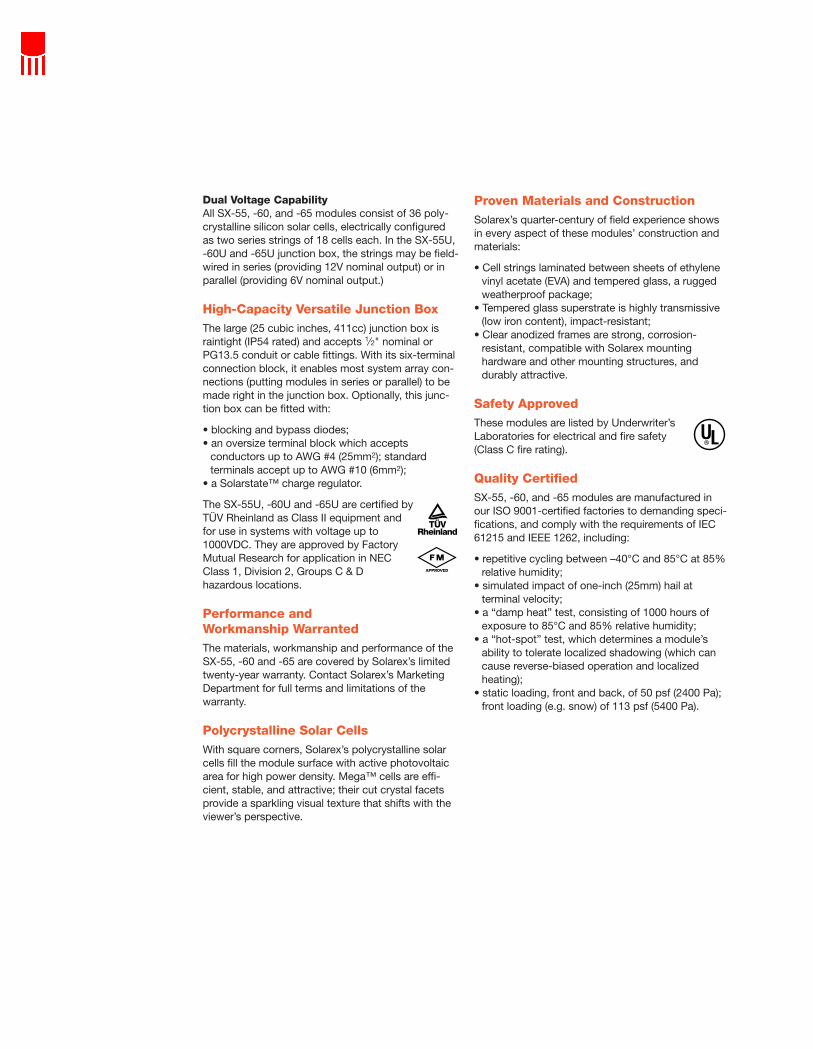
Dual Voltage CapabilityAll SX-55, -60, and -65 modules consist of 36 poly-crystalline silicon solar cells, electrically configuredas two series strings of 18 cells each. In the SX-55U,-60U and -65U junction box, the strings may be field-wired in series (providing 12V nominal output) or inparallel (providing 6V nominal output.)
High-Capacity Versatile Junction BoxThe large (25 cubic inches, 411cc) junction box israintight (IP54 rated) and accepts 1⁄2" nominal orPG13.5 conduit or cable fittings. With its six-terminalconnection block, it enables most system array con-nections (putting modules in series or parallel) to bemade right in the junction box. Optionally, this junc-tion box can be fitted with:
• blocking and bypass diodes;• an oversize terminal block which accepts
conductors up to AWG #4 (25mm2); standardterminals accept up to AWG #10 (6mm2);
• a Solarstate™ charge regulator.
The SX-55U, -60U and -65U are certified byTÜV Rheinland as Class II equipment andfor use in systems with voltage up to1000VDC. They are approved by FactoryMutual Research for application in NECClass 1, Division 2, Groups C & D hazardous locations.
Performance and Workmanship WarrantedThe materials, workmanship and performance of theSX-55, -60 and -65 are covered by Solarex’s limitedtwenty-year warranty. Contact Solarex’s MarketingDepartment for full terms and limitations of the warranty.
Polycrystalline Solar CellsWith square corners, Solarex’s polycrystalline solarcells fill the module surface with active photovoltaicarea for high power density. Mega™ cells are effi-cient, stable, and attractive; their cut crystal facetsprovide a sparkling visual texture that shifts with theviewer’s perspective.
Proven Materials and ConstructionSolarex’s quarter-century of field experience showsin every aspect of these modules’ construction andmaterials:
• Cell strings laminated between sheets of ethylenevinyl acetate (EVA) and tempered glass, a ruggedweatherproof package;
• Tempered glass superstrate is highly transmissive(low iron content), impact-resistant;
• Clear anodized frames are strong, corrosion-resistant, compatible with Solarex mountinghardware and other mounting structures, anddurably attractive.
Safety ApprovedThese modules are listed by Underwriter’sLaboratories for electrical and fire safety(Class C fire rating).
Quality CertifiedSX-55, -60, and -65 modules are manufactured inour ISO 9001-certified factories to demanding speci-fications, and comply with the requirements of IEC61215 and IEEE 1262, including:
• repetitive cycling between –40°C and 85°C at 85%relative humidity;
• simulated impact of one-inch (25mm) hail atterminal velocity;
• a “damp heat” test, consisting of 1000 hours ofexposure to 85°C and 85% relative humidity;
• a “hot-spot” test, which determines a module’sability to tolerate localized shadowing (which cancause reverse-biased operation and localizedheating);
• static loading, front and back, of 50 psf (2400 Pa);front loading (e.g. snow) of 113 psf (5400 Pa).
Notes1. These specifications represent the performance of typical 12V
modules as measured at their output terminals (or cable termina-tion), and do not include the effect of such additional equipment asdiodes. The specifications are based on measurements made inaccordance with ASTM E1036-85 corrected to SRC (StandardReporting Conditions, also known as STC or Standard TestConditions), which are:
• illumination of 1 kW/m2 (1 sun) at spectral distribution of AM 1.5(ASTM E892-87 global spectral irradiance);
• cell temperature of 25°C.
For characteristics of modules in 6V configuration, divide the 12Vvoltage characteristics by 2 and multiply current characteristics by 2. Power values are unchanged.
2. When illuminated, the cells in a module operate hotter than the am-bient temperature. NOCT (Nominal Operating Cell Temperature) isan indicator of this temperature differential, and is the cell tempera-ture under Standard Operating Conditions: ambient temperature of20°C, solar irradiation of 0.8 kW/m2, and wind speed of 1 m/s.
3. These specifications do not include the effect of light-induceddegradation, which can result in approximately a 3% reduction inpower output after exposure to sunlight.
Mechanical CharacteristicsWeightD configurations 14.4 pounds (6.5 kg)U configurations 15.9 pounds (7.2 kg)
Typical Electrical Characteristics(1)
SX-55 SX-60 SX-65Maximum power (Pmax) 55W 60W 65WVoltage at Pmax (Vmp) 16.5V 16.8V 17.2VCurrent at Pmax (Imp) 3.33A 3.56A 3.77AGuaranteed minimum Pmax 50W 55W 60WShort-circuit current (Isc) 3.69A 3.87A 4.06AOpen-circuit voltage (Voc) 20.6V 21.0V 21.5VTemperature coefficient of Isc (0.065±0.015)%/°C Temperature coefficient of Voc –(80±10)mV/°CTemperature coefficient of power –(0.5±0.05)%/°C NOCT2 47°±2°C
4.0
3.5
3.0
2.5
2.0
1.5
1.0
0.5
0.0
Cu
rren
t (A
)
Voltage (V)0 5 10 15 20 25
SX-55 I-V Curves
T=0°CT=25°CT=50°CT=75°C
4.5
4.0
3.5
3.0
2.5
2.0
1.5
1.0
0.5
0.0
Cu
rren
t (A
)
Voltage (V)0 5 10 15 20 25
SX-60 I-V Curves
T=0°CT=25°CT=50°CT=75°C
4.5
4.0
3.5
3.0
2.5
2.0
1.5
1.0
0.5
0.0
Cu
rren
t (A
)
Voltage (V)0 5 10 15 20 25
SX-65 I-V Curves
T=0°CT=25°CT=50°CT=75°C
SH
OR
TPA
GE
—tr
im t
his
port
ion
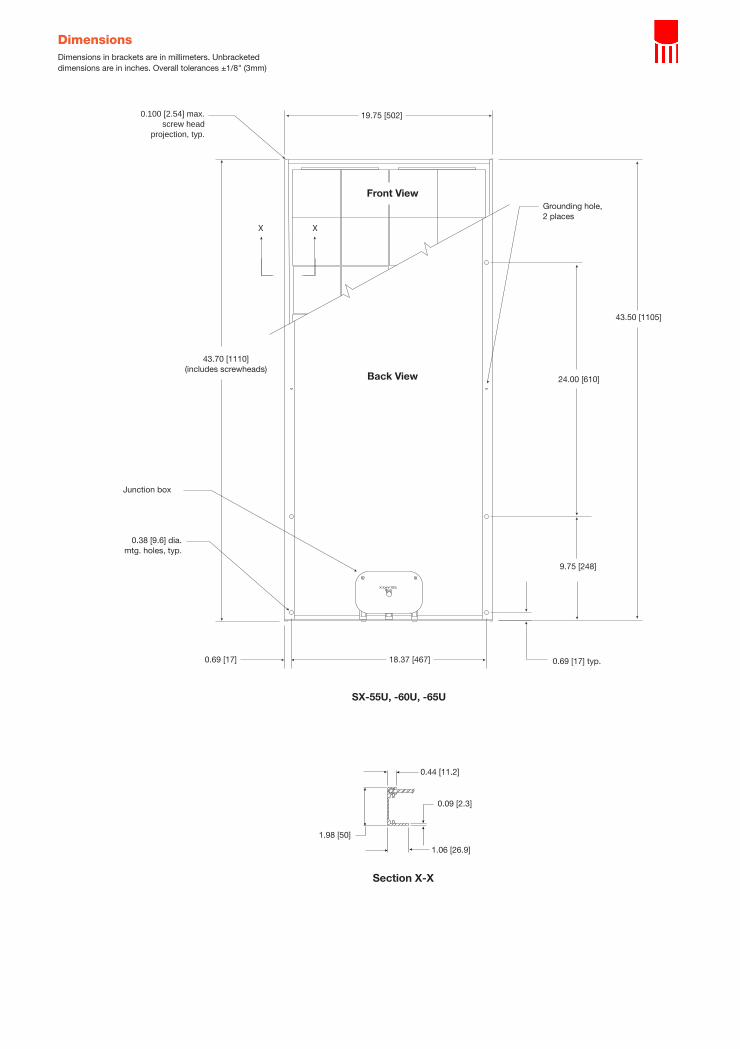
19.75 [502]
43.70 [1110](includes screwheads)
Junction box
0.38 [9.6] dia.mtg. holes, typ.
0.100 [2.54] max.screw head
projection, typ.
Grounding hole,2 places
43.50 [1105]
24.00 [610]
9.75 [248]
0.69 [17] typ.18.37 [467]0.69 [17]
Front View
Back View
SX-55U, -60U, -65U
XX
0.44 [11.2]
0.09 [2.3]
1.06 [26.9]
1.98 [50]
Section X-X
DimensionsDimensions in brackets are in millimeters. Unbracketeddimensions are in inches. Overall tolerances ±1/8" (3mm)

SH
OR
TPA
GE
—tr
im t
his
port
ion
0.100 [2.54] max.screw head
projection, typ.
Front View
Back View
SX-55D, -60D, -65D
21.60 [549]
43.68 [1110](includes screwheads)
Cable 15 feet lg.
Enclosure
0.38 [9.6] dia.mtg. holes, typ.
0.44 [11] 20.72 [526] 0.68 [17] typ.
9.74 [247]
24.00 [610]
43.48 [1104]
Grounding hole,2 places.
ZZ
1.50 [38.1]
0.05 [1.3]
0.43 [10.8]
0.99 [25.1]
Section Z-Z
DimensionsDimensions in brackets are in millimeters. Unbracketeddimensions are in inches. Overall tolerances ±1/8" (3mm)

SX-75, SX-80 and SX-85
Photovoltaic Modules
Applications of these modules, which generate peakpower of 75 watts, 80 watts and 85 watts respec-tively, encompass virtually all applications wherephotovoltaics are a feasible energy source, includingtelecommunication systems, pumping and irrigation,cathodic protection, remote villages and homes, andland-based navigation aids. They are engineeredunder Solarex’s IntegraSystem™ system integrationconcept, which ensures compatibility with otherSolarex subsystems and components (support hard-ware, regulators, etc.) and easy system assembly.Their rugged Universal frame is suitable for industrialuse, and exceeds the requirements of all certifyingagencies.
Dual Voltage CapabilityThese modules consist of 36 polycrystalline siliconsolar cells, electrically configured as two seriesstrings of 18 cells each. Shipped in 12V nominal con-figuration, with cell strings series-wired, the modulesmay easily be switched to 6V nominal output in thefield by moving leads in the junction box.
High-Capacity Versatile Junction BoxThe large (25 cubic inches, 411cc) junction box israintight (IP54 rated) and accepts 1⁄2" nominal orPG13.5 conduit or cable fittings. With its six-terminalconnection block, it enables most system array con-nections (putting modules in series or parallel) to bemade right in the junction box. Optionally, this junc-tion box can be fitted with:
• blocking and bypass diodes;• an oversize terminal block which accepts
conductors up to AWG #4 (25mm2); standardterminals accept up to AWG #10 (6mm2);
• a Solarstate™ charge regulator.
SX-75, SX-80 and SX-85 photovoltaic modules are the largestof Solarex’s new SX™ module series, providing cost-effectivephotovoltaic power for general use. They operate DC loadsdirectly or, in an inverter-equipped system, AC loads. Theyare suitable for single or multiple-module systems and, with36 polycrystalline cells in series, charge batteries efficientlyin virtually any climate. Their materials, design and con-struction reflect Solarex’s quarter-century of experience.
630 Solarex Court Frederick
Maryland 21703 www.solarex.com
Phone: (301) 698-4200Fax: (301) 698-4201
© Solarex 1999
Specifiications subject to change without notice
6049-1 4/99
Universal frame.
SX-80
The Natural Source for Electricity™Solarex’s polycrystallinesilicon modules requiremuch less energy tomanufacture thancomparable mono-crystalline products,giving a significantlyfaster energy paybackand larger lifetimecontribution of greenenergy.

Performance and Workmanship WarrantedThe materials, workmanship and performance of theSX-75, -80 and -85 are covered by Solarex’s limitedtwenty-year warranty. Contact Solarex’s MarketingDepartment for full terms and limitations of the warranty.
Polycrystalline Solar CellsWith square corners, Solarex’s polycrystalline solarcells fill the module surface with active photovoltaicarea for high power density. Mega™ cells are effi-cient, stable, and attractive; their cut crystal facetsprovide a sparkling visual texture that shifts with theviewer’s perspective.
Proven Materials and ConstructionSolarex’s quarter-century of field experience showsin every aspect of these modules’ construction andmaterials:
• Cell strings laminated between sheets of ethylenevinyl acetate (EVA) and tempered glass, a ruggedweatherproof package;
• Tempered glass superstrate is highly transmissive(low iron content), impact-resistant;
• Clear anodized frames are strong, corrosion-resistant, compatible with Solarex mountinghardware and other mounting structures, anddurably attractive.
Safety ApprovedThese modules are listed by Underwriter’sLaboratories for electrical and fire safety(Class C fire rating), certified by TÜVRheinland as Class II equipment and foruse in systems with voltage up to1000VDC, and approved by FactoryMutual Research for application in NECClass 1, Division 2, Groups C & D hazardous locations.
Quality CertifiedSX-75, -80, and -85 modules are manufactured inour ISO 9001-certified factories to demanding speci-fications, and comply with the requirements of IEC61215 and IEEE 1262, including:
• repetitive cycling between –40°C and 85°C at 85%relative humidity;
• simulated impact of one-inch (25mm) hail atterminal velocity;
• a “damp heat” test, consisting of 1000 hours ofexposure to 85°C and 85% relative humidity;
• a “hot-spot” test, which determines a module’sability to tolerate localized shadowing (which cancause reverse-biased operation and localizedheating);
• static loading, front and back, of 50 psf (2400 Pa);front loading (e.g. snow) of 113 psf (5400 Pa).
Typical Electrical Characteristics(1)
Notes1. These specifiications represent the performance of typical 12
modules as measured at their output terminals, and do not includethe effect of such additional equipment as diodes or cables. Thespecifiications are based on measurements made in accordancwith ASTM E1036-85 corrected to SRC (Standard ReportingConditions, also known as STC or Standard Test Conditions),which are:
• illumination of 1 kW/m2 (1 sun) at spectral distribution of AM 1.5(ASTM E892-87 global spectral irradiance);
• cell temperature of 25°C.
For characteristics of modules in 6V confiiguration, divide the 12voltage characteristics by 2 and multiply current characteristics by 2. Power values are unchanged.
2. U.S. NEC rating.
3. When illuminated, the cells in a module operate hotter than the am-bient temperature. NOCT (Nominal Operating Cell Temperature) isan indicator of this temperature differential, and is the cell tempera-ture under Standard Operating Conditions: ambient temperature of20°C, solar irradiation of 0.8 kW/m2, and wind speed of 1 m/s.
4. These specifiications do not include the effect of light-inducedegradation, which can result in approximately a 3% reduction inpower output after exposure to sunlight.
SX-75 SX-80 SX-85Maximum power (Pmax) 75W 80W 85WVoltage at Pmax (Vmp) 16.5V 16.8V 17.1VCurrent at Pmax (Imp) 4.54A 4.75A 4.97AGuaranteed minimum Pmax 70W 75W 80WShort-circuit current (Isc) 4.97A 5.17A 5.30AOpen-circuit voltage (Voc) 20.7V 21.0V 21.3VMaximum system voltage(2) 600VTemperature coefficient of Isc (0.065±0.015)%/°CTemperature coefficient of Voc –(80±10)mV/°C Temperature coefficient of power –(0.5±0.05)%/°C NOCT(3) 47±2°C

6.0
5.0
4.0
3.0
2.0
1.0
0
Cu
rren
t (A
)
Voltage (V)0 5 10 15 20 25
SX-75 I-V Curves
T=0°CT=25°CT=50°CT=75°C
6.0
5.0
4.0
3.0
2.0
1.0
0
Cu
rren
t (A
)
Voltage (V)0 5 10 15 20 25
SX-80 I-V Curves
T=0°CT=25°CT=50°CT=75°C
6.0
5.0
4.0
3.0
2.0
1.0
0
Cu
rren
t (A
)
Voltage (V)0 5 10 15 20 25
SX-85 I-V Curves
T=0°CT=25°CT=50°CT=75°C
Mechanical CharacteristicsWeight20.9 pounds (9.5 kg)

0.38 [9.6] X 0.50 [12.7] dia.mtg. holes, typ.
0.100 [2.54] max.screw head
projection, typ.
SX-75, -80, -85
Back view
Front view
Junction box
18.37 [467]0.69 [17]
Grounding hole,2 places.
57.51 [1461](includes screwheads)
X X
19.75 [502]
57.31 [1456]
38.00 [965]
9.66 [245]
0.69 [17] typ.
0.44 [11.2]
0.09 [2.3]
1.06 [26.9]
1.98 [50]
Section X-X
DimensionsDimensions in bracketsare in millimeters.Unbracketed dimensionsare in inches. Overalltolerances ±1/8" (3mm)


IntegraSystem hardware is adaptable, reliable, easyto use, and uses a standardized complement ofwell-tested components. Its modular design allowsit to precisely match your array support require-ments and the characteristics of your site. It meetsstringent specifications in any of its approved con-figurations.
Complete Integrated KitsIntegraSystem hardware kits are complete andfully compatible with Solarex modules, panels andwiring kits. The interfaces between each kit andother array components are clearly identified inthis brochure.
A Pre-engineered Support SystemIntegraSystem kits are fully documented, easy toassemble, and compatible with other indicatedSolarex products. Assembled arrays will withstandwinds in excess of 125 mph (200 km/hr).
Engineered for Severe EnvironmentsAll kit materials are selected for corrosion resis-tance in severe climates. The largest mounting kit,
the HPF1 rack structure, uses galvanized steelstructural members. The structural members ofsmaller kits are fabricated from corrosion-resistantaluminum alloys and assembled with stainlesssteel fasteners.
Tested in the Real WorldTwenty years of real-world testing and designdevelopment means IntegraSystem array hardwareperforms well anywhere. Solarex’ rigorous materi-al specifications ensure consistent quality.
Adjustable for Any LatitudeIntegrasystem kits allow arrays to be adjusted toand securely fixed at the optimum tilt angle forsites at any latitude. The tilt angle range (indegrees of variance from horizontal) is shown inthe kit specifications which follow.
The IntegraSystem Concept
The key to the IntegraSystemTM concept is pre-engineering. Every IntegraSystem PV compo-nent or subsystem is electrically and mechani-cally pre-engineered for reliability, compatibili-ty with other IntegraSystem components, easeof installation and compliance with code andsafety requirements. This pre-engineeringprocess includes:
• identifying the subsystem’s interfaceswith other components and ensuringcompatibility;
• applying design and selection criteriathat assure compliance with NECrequirements and efficient, safe, reli-able system operation;
• applying economies of scale to theprocess of system design and compo-nent selection and procurement.
IntegraSystem enables a customer toselect PV components with confidencethat they will assemble easily into an effi-cient, reliable, cost-effective power system.
630 So l a rex Cour t , F rede r i ck , Mary l and 21703 USA • PHONE (301) 698 -4200• FAX (301) 698 -4201
This publication describes Solarex’s IntegraSystemphotovoltaic array support hardware. This hard-ware is offered in a range of types, capable ofmounting arrays as small as one module and aslarge as several dozen kilowatts to buildings,poles, and ground-based foundations.
R
Solarex IntegraSystemTM Photovoltaic Array Support Systems

GENERAL SPECIFICATIONSWind loading Minimum 125 mph (200 km/hr)
Materials Hot-dip galvanized Schedule 40steel pipe
5052 or 6061 (as appropriate) clearanodized structural aluminum alloy
Type 316 stainless steel fasteners
SINGLE-MODULE MOUNTINGHARDWAREIntegraSystem kits are available for mounting sin-gle modules to cylindrical or square poles ormasts and horizontal, vertical or sloping structuralsurfaces. These kits include all necessary hard-ware and fasteners with the exception of the fasteners that attach the completed assembly tothe mounting surface; fasteners required for thisfunction vary greatly since mount-ing surfaces vary greatly.The kits include com-plete installationinstructions and recommendations forattachment hardware
(e.g., hose clamps, U-bolts, lag screws,etc.) for use oncommon surfaces.
Some of Solarex’ssmall PV modules are
available with twostyles of frame: the
“Universal” frame and the Multimount™ frame.Mounting kits for each frame style are available.
Mounting Kits for Small Module withUniversal FrameThese kits consist of a mounting bracket, a mod-ule bracket and required assembly fasteners. Theymount one MSX-10, -18, -30 or -40 with universalframe to a vertical pole (cylindrical or square) or aflat structural surface.
• Continuous adjustment of module tilt angle from0º to 90º.
• Heavy-duty aluminum alloy brackets with clearanodized finish.
• Fits poles with outside diameter 2-7/8" to 12"using hose clamps, 1" to 4" using U-bolts.
Module Mounting KitMSX-18, -30, and -40 HPM18-30MSX-10 HPM10U
Mounting Kit for Small Module withMultimount FrameThese kits mount one MSX-5, -10, -18, or -30 withMultimount™ frame to a vertical pole (cylindricalor square) or a flat structural surface.
• Continuous adjustment of module to any desiredtilt; tilt angles are imprinted on the bracket.
• Fits poles with outside diameter 1" to 4"
Module Mounting KitMSX-18 and 30 HPM18-30MMSX-5 and 10 HPM5-10
Multimount
Universal

Large Module Flat-surface Mounting Kits
These kits attach a single large module to a horizontal, vertical, or sloping flat sur-
face. Each kit consists of two heavy-duty type aluminum alloy brackets,
two aluminum alloy angle brack-ets, and assembly fasteners.
• Continuous adjustment oftilt angle from 0º to 90º
Module Mounting KitMSX-50, -53, -56, -60, and -64 HFMH60MSX-77, -83 HFMH80
Mounting Kits for Large Module withLong Axis HorizontalThese kits consist of a crossarm bracket, two feet,two angle brackets, and required fasteners. Theymount a single large Solarex module to a verticalpole or other flat vertical, horizontal or slopingsurface, supporting the module with its long axishorizontal.
• Continuous adjustment of tilt angle from 0º to90º
• Fits poles with outside diameter 2" to 12-3/4"
Module Mounting KitMSX-50, -53, -56, -60, and -64 HPMH53-60MSX-77, -83 HPMH80
Mounting Kit for Large Module withLong Axis Vertical, Item HPMV53-60This kit consists of six brackets, a two-sectionadjustable leg assembly, and assembly fasteners. Itmounts a single large Solarex module to a verticalpole or other flat vertical surface, supporting themodule with its long axis vertical.
• Applicability: Single MSX-50, -53, -56, -60 or -64module
• Incremental adjustment of tilt angle from 15º to70º.
• Fits poles with outside diameter 1" to 4"

Mounting Kit for Marine ModulesThese kits consist of two brackets and assemblyhardware, and mount an MSX-20MM or -38 MM toa vertical or horizontal beam or a flat structuralsurface.
• Continuous adjustment of tilt anglefrom 0º to 90º.
• Fits poles with outside diameter 1" to 2-1/2"
Module Mounting Kit Vertical Beam Horizontal Beam
MSX-20MM HPMV20MM HPMH20MMMSX-38MM HPMV38MM HPMH38MM
MOUNTING HARDWARE FOR MULTIPLE-MODULE ARRAYSThe IntegraSystem modular approach to mountinga multiple-module array considers the support system as three subassemblies, which aredescribed in the remainder of this brochure.When ordering IntegraSystem hardware for a site,ensure that all three hardware categories are considered in your design.
Panel assembly kits which combine modulesinto panels ranging in size from 1 module (a 1Xpanel) to 6 modules (a 6X panel).
Leg kits which hold panels at the appropriate tiltangle
Site structural interface. This must accept themounting feet of the leg kits and be able to withstand mechanical loading transferred by thearray. It may be provided by Solarex or theCustomer. Typical Customer-furnished interfacesinclude poured concrete pads, roof-mountedexternal beams, and horizontal or vertical poles.
Panel Assembly Kits, Items HPKIntegraSystem panel assembly kits assemble multi-ple modules into panels, using longitudinal beamswhich mechanically integrate the modules, addrigidity to the panel, and accept mounting feet
and legs. Each panelassembly kit consists of
two beams fabricatedfrom angle stock and
the fasteners neces-sary to attach
modules to thebeams.
Kits applica-ble to
MSX-40, -50, -53,
-56, -60
HPMH KIts
HPMV KIts
HPK KIts

and -64 modules are identified by item numbersranging from HPK2X (for a 2-module panel)through HPK6X (for a 6-module panel). The itemnumbers of most kits for MSX-77, -83, and -120modules include a module designator suffix, asshown in Table 1.
Table 1HPK Panel Assembly Kits forMSX-77, -83 and -120 Modules
Panel Configuration HPK ItemNumber
2 MSX-77 or -83 modules HPK2X-804 MSX-77 or -83 modules HPK4X-80
1 MSX-120 module HPK1X-1202 MSX-120 modules HPK4X3 MSX-120 modules HPK3X-120
Adjustable Leg kits, Items HAFMSEach leg kit consists of two adjustable two-sectionlegs (adjustable in 4-inch increments), four “feet”,and required assembly hardware. The kits securelysupport a panel at the desired tilt angle on hori-zontal, vertical and sloping surfaces. Table 2 pro-vides guidance in selecting the correct leg kit forsupporting a panel on a Customer-supplied hori-
zontal foundation or mounting surface. Table 3 (over) provides guidance in
selecting the correct legkit for supporting a
panel on a verticalmounting
surface.
Note that these kits do not include hardware forattaching the feet to the supporting surface.
Table 2Selecting HAFMS Leg Kits for
Mounting Panels on Horizontal Surfaces
Panel Configuration Leg Kit Tilt Range
2 or 3 MSX-40, -50, -60 (series) modules HAFMS12 12° to 30°2 MSX-77 or -83 modules HAFMS20 24° to 63°1 MSX-120 module HAFMS28 35° to 88°
HAFMS12 10° to 22°4 MSX-40, -50, -60 (series) modules HAFMS20 19° to 42°2 MSX-120 modules HAFMS28 28° to 68°
HAFMS36 36° to 89°
HAFMS12 7° to 14°5 or 6 MSX-40, -50, -60 (series) modules HAFMS20 8° to 26°4 MSX-77 or -83 modules HAFMS28 10° to 38°3 MSX-120 modules HAFMS36 19° to 50°
HAFMS36 plus36” extension 43° to 77°
HAFMS KIts
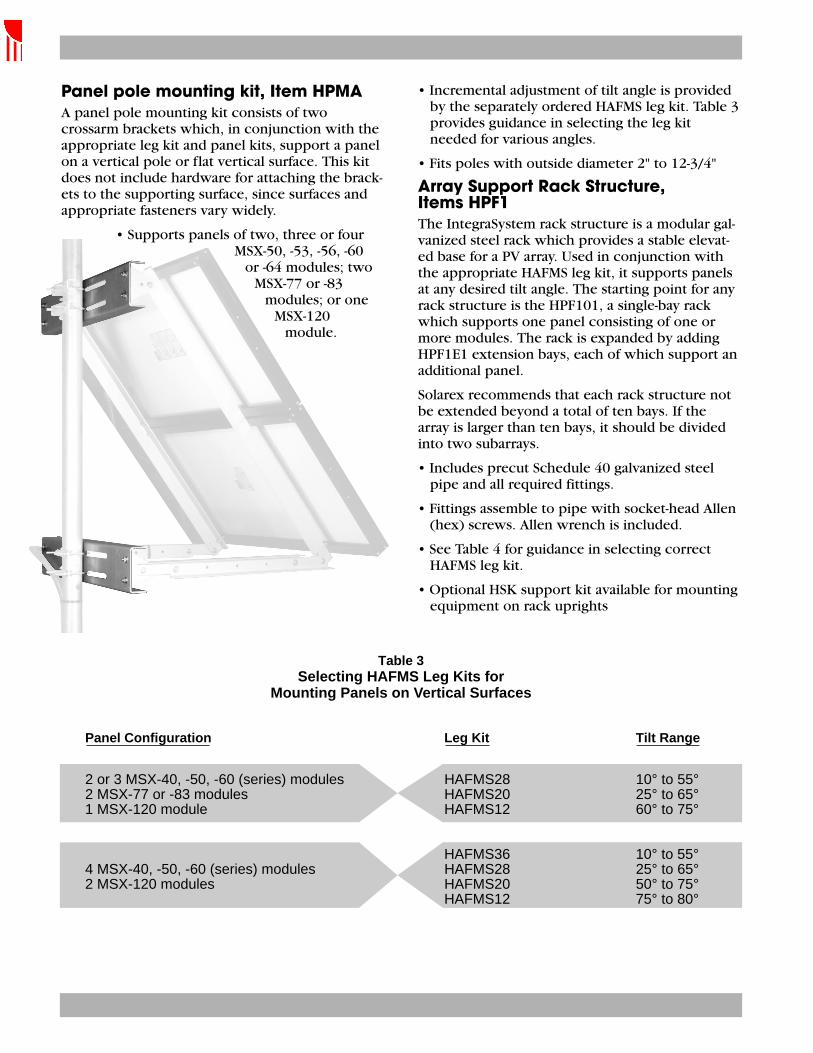
Table 3Selecting HAFMS Leg Kits for
Mounting Panels on Vertical Surfaces
Panel pole mounting kit, Item HPMAA panel pole mounting kit consists of twocrossarm brackets which, in conjunction with theappropriate leg kit and panel kits, support a panelon a vertical pole or flat vertical surface. This kitdoes not include hardware for attaching the brack-ets to the supporting surface, since surfaces andappropriate fasteners vary widely.
• Supports panels of two, three or fourMSX-50, -53, -56, -60
or -64 modules; twoMSX-77 or -83
modules; or oneMSX-120
module.
• Incremental adjustment of tilt angle is providedby the separately ordered HAFMS leg kit. Table 3provides guidance in selecting the leg kit needed for various angles.
• Fits poles with outside diameter 2" to 12-3/4"
Array Support Rack Structure, Items HPF1The IntegraSystem rack structure is a modular gal-vanized steel rack which provides a stable elevat-ed base for a PV array. Used in conjunction withthe appropriate HAFMS leg kit, it supports panelsat any desired tilt angle. The starting point for anyrack structure is the HPF101, a single-bay rackwhich supports one panel consisting of one ormore modules. The rack is expanded by addingHPF1E1 extension bays, each of which support anadditional panel.
Solarex recommends that each rack structure notbe extended beyond a total of ten bays. If thearray is larger than ten bays, it should be dividedinto two subarrays.
• Includes precut Schedule 40 galvanized steelpipe and all required fittings.
• Fittings assemble to pipe with socket-head Allen(hex) screws. Allen wrench is included.
• See Table 4 for guidance in selecting correctHAFMS leg kit.
• Optional HSK support kit available for mountingequipment on rack uprights
2 or 3 MSX-40, -50, -60 (series) modules HAFMS28 10° to 55°2 MSX-77 or -83 modules HAFMS20 25° to 65°1 MSX-120 module HAFMS12 60° to 75°
HAFMS36 10° to 55°4 MSX-40, -50, -60 (series) modules HAFMS28 25° to 65°2 MSX-120 modules HAFMS20 50° to 75°
HAFMS12 75° to 80°
Panel Configuration Leg Kit Tilt Range
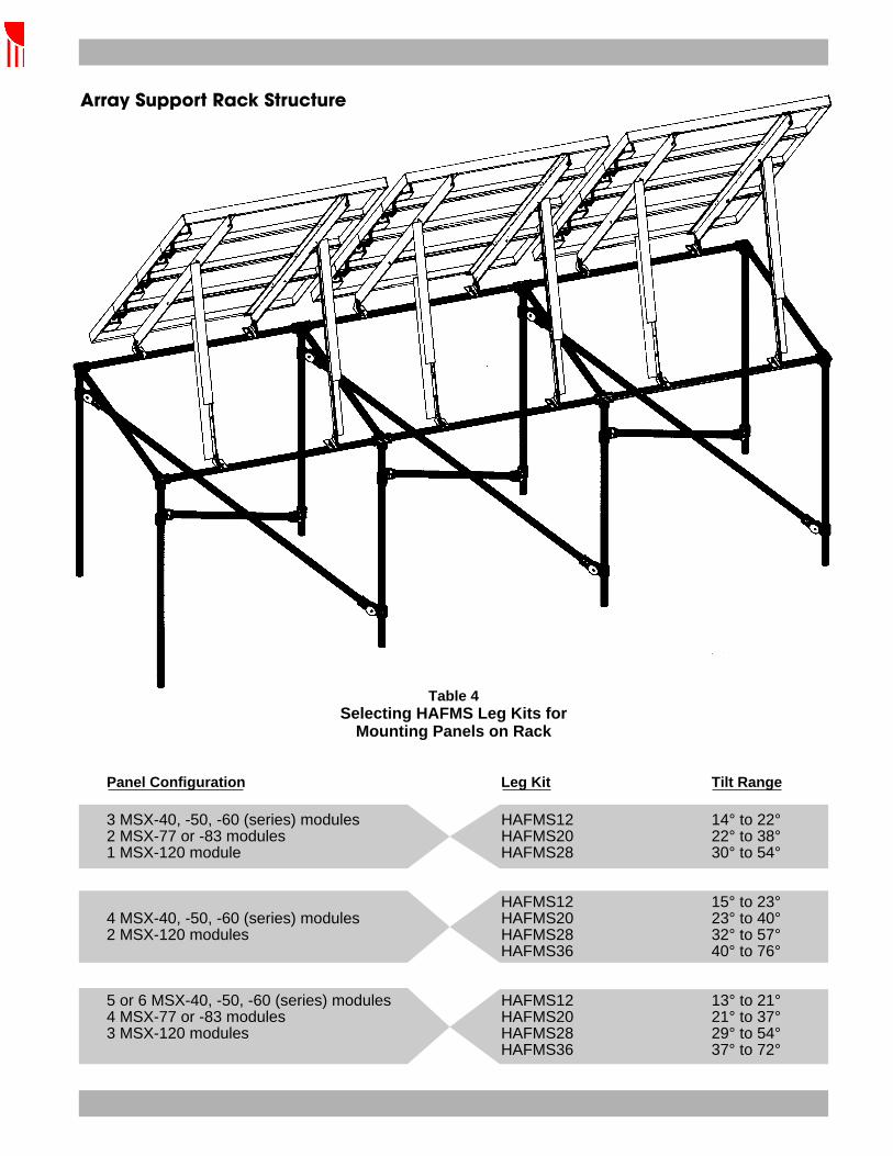
3 MSX-40, -50, -60 (series) modules HAFMS12 14° to 22°2 MSX-77 or -83 modules HAFMS20 22° to 38°1 MSX-120 module HAFMS28 30° to 54°
HAFMS12 15° to 23°4 MSX-40, -50, -60 (series) modules HAFMS20 23° to 40°2 MSX-120 modules HAFMS28 32° to 57°
HAFMS36 40° to 76°
5 or 6 MSX-40, -50, -60 (series) modules HAFMS12 13° to 21°4 MSX-77 or -83 modules HAFMS20 21° to 37°3 MSX-120 modules HAFMS28 29° to 54°
HAFMS36 37° to 72°
Table 4Selecting HAFMS Leg Kits for
Mounting Panels on Rack
Array Support Rack Structure
Panel Configuration Leg Kit Tilt Range

The HSK12 kit includes channel brackets 12" long;the HSK24 kit includes 24" channel brackets.
Selecting a Fixed Tilt AngleThe angle at which an array is tilted affects its abil-ity to collect solar energy. Some arrays are contin-uously or periodically adjusted to account for thesun’s daily or seasonal movement, but at remotesites it is usually more cost-effective for the arrayto be installed at a fixed angle. This angle varieswith site latitude, load characteristics and otherfactors, and must be known to enable orderingsome of the support hardware in this publication.
Accurate design of a PV power system is a com-plex process, requiring a computer simulation ofthe on-site interaction between the load and thepower system. The optimum array tilt angle is oneproduct of this process, which can be performedby Solarex representatives.
Table 5 provides approximate tilt angle recom-mendations, by site latitude, for typical installa-tions. These recommendations are based on certain assumptions, most importantly that theelectrical load on the system is the same every dayof the year. This table is not intended to replace acomprehensive system design process.
Tilt angle is not critical: variations of up to 5º usu-ally make little difference in an array’s ability tosupport a given load.
If modules are not cleaned regularly, it is recom-mended that they not be mounted at an angle flatter than 15º. Flatter angles cannot take fulladvantage of the cleansing action of rainfall.
Table 5Approximate Array Tilt for Loads
with Consistent Daily Energy Requirements
Latitude of Site Recommended Tilt Angle
0-4° 10°5-20° Add 5° to local latitude21-45° Add 10° to local latitude46-65° Add 15° to local latitude66-75° 80°
For more information, contact:
© 1993 Solarex Corporation SPECIFICATIONS SUBJECT TO CHANGE WITHOUT NOTICE 6086-2 8/95Printed on Recycled Paper
HSK Enclosure Attachment KitsHSK attachment kits are designed to supportequipment (typically an enclosure containingswitchgear or a controller) on a vertical memberof the HPF rack base. Each kit con-sists of two channel brackets, clampsand other hardware to mount thebrackets to the rack.

Atlantic Solar Products, Inc., offers the following Side of Pole Mounts:
HPM 5-10U HPM 5-10 Hinge/ HPM 18-30 HPMH 60
Model FitsHPM 5/10 U SX-5-M, SX-10 -MHPM 5/10 Hinge SX-5, SX-10 Both U and M SeriesHPM 18/30 SX-20, 30,40 Both U and M SeriesHPMH-60 SX-50,55,60,65
UniRac Model
Number
Sch.40Pole Size (in.)
BP Solar Kyocera Siemens UniSolar270 275 585 590
SX75TU
SX55SX60SX65
SX75SX80SX85
SX110SX120
MST 43
MSX 120
2150 3160 4160 5170
SX150
KC60KC70KC80
KC120 SM100SM110
SP65SP70SP75
SP130SP140SP150
SR90 SR100 US64
U-11 and U-PS Series Side of Pole Racks
U-11/20M 2.5 - 1 - - - - - - - - - - - -
U-11/20XL 2.5 - - 1 - - - - - - - - - - -
U-11/24M 2.5 1 - - - - - - - - - 1 - 1 -
U-11/24L 2.5 - - - - - - - - - - - - - -
U-11/28M 2.5 - - - - - - - 1 - 1 - - - -
U-11/28L 2.5 - - - - - - - - - - - - - -
U-PS/24M 2.5 - - - - - - - - - - - - 1 -
U-PS/26M 2.5 - - - - 1 - - - - 1 - - - -
U-PS/26XXL
2.5 - - - - - - - - 1 - - - - -
U-PS/28L 2.5 - - - - - - - - - - - - - -
U-PS/30XL 2.5 - - - - - - - - - - - - - 1
U-PS/30XXL
2.5 - - - 1 - - - - - - - - - -
U-PS/32M 2.5 - - - - - - - - - - - 1 - -
U-PS/32XL 2.5 - - - - - - 1 - - - - - - -
U-PS/40M 2.5 - 2 - - - 1 - - - - - - - -
U-PS/40XL 2.5 - - 2 - - - - - - - - - - -
U-PS/44M 2.5 2 - - - - - - - - - 2 - - -
U-PS/44L 2.5 - - - - - - - - - - - - - -
3
Page 1 of 2Side of Pole Mounts - Wiring & Mounts - Atlantic Solar Products, Inc.
10/27/2003
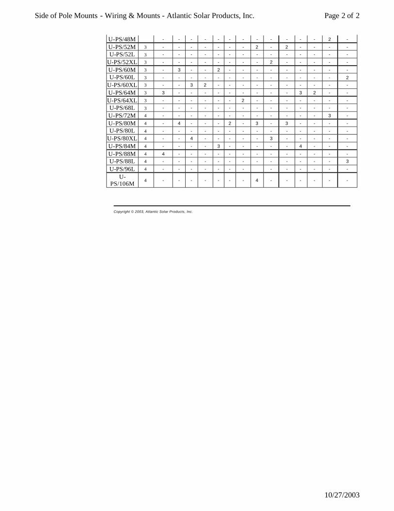
U-PS/48M - - - - - - - - - - - - 2 -
U-PS/52M 3 - - - - - - - 2 - 2 - - - -
U-PS/52L 3 - - - - - - - - - - - - - -
U-PS/52XL 3 - - - - - - - - 2 - - - - -
U-PS/60M 3 - 3 - - 2 - - - - - - - - -
U-PS/60L 3 - - - - - - - - - - - - - 2
U-PS/60XL 3 - - 3 2 - - - - - - - - - -
U-PS/64M 3 3 - - - - - - - - - 3 2 - -
U-PS/64XL 3 - - - - - - 2 - - - - - - -
U-PS/68L 3 - - - - - - - - - - - - - -
U-PS/72M 4 - - - - - - - - - - - - 3 -
U-PS/80M 4 - 4 - - - 2 - 3 - 3 - - - -
U-PS/80L 4 - - - - - - - - - - - - - -
U-PS/80XL 4 - - 4 - - - - - 3 - - - - -
U-PS/84M 4 - - - - 3 - - - - - 4 - - -
U-PS/88M 4 4 - - - - - - - - - - - - -
U-PS/88L 4 - - - - - - - - - - - - - 3
U-PS/96L 4 - - - - - - - - - - - - -
U-PS/106M
4 - - - - - - - 4 - - - - - -
Copyright © 2003, Atlantic Solar Products, Inc.
Page 2 of 2Side of Pole Mounts - Wiring & Mounts - Atlantic Solar Products, Inc.
10/27/2003

SOLAR CONTROLLERSOLAR CONTROLLERSUNSAVERTM
Morningstar’s SunSaver is the world’s leadingsmall solar controller for both professional andconsumer applications.
SunSaver’s technology provides:• Exceptional Reliability• PWM Battery Charging• Consistent High Quality
The SunSaver’s advanced design delivers outstanding performance and value. TheSunSaver’s low cost is made possible byMorningstar’s unique approach to design and manufacturing:
• Automated production• ISO 9002 quality programs• Latest power electronic technologies• Latest control and logic technologies• High volume manufacturing
Features:• Eight versions available (see back)
12 and 24 volts6, 10 and 20 amps
• 100% solid state
• Series design (not shunt)
• True 0 to 100% PWM duty cycle
• Setpoint accuracy to 35 mV
• Rated for 25% overloads
• Fully encapsulated in epoxy potting
• Marine rated terminals / anodized case
• Temperature compensation
• Sealed / Flooded battery select
• No need to derate
• Parallel for 40 amps or more
• Green charging / Red LVD indicators

WARRANTY: Five year warranty period. Contact Morningstar or your authorized distributor for complete terms.
1098 Washington Crossing RoadWashington Crossing, PA 18977 USATel: 215-321-4457 Fax: 215-321-4458E-mail: [email protected]: www.morningstarcorp.com
PRINTED IN USA 204E-R1-2/99
AUTHORIZED MORNINGSTAR DISTRIBUTOR:
SUNUNSAAVERVERTMTM T E C H N I C A L S P E C I F I C A T I O N S
Mechanical SpecificationsWire size #10 AWG (5.2 mm2)Anodized aluminum caseMarine rated terminalsEpoxy encapsulatedWeight is 8 oz (0.23 kg)
Electrical Specifications12 Volt 24 Volt
Rated Solar Input 6.5 /10/20 ARated Load 6/10/20 A25% Current Overload 5 min. 5 min.Regulation Voltage:
Sealed Battery 14.1 V 28.2 VFlooded Battery 14.4 V 28.8 V
Load Disconnect 11.5 V 23.0 VLVD Reconnect 12.6 V 25.2 VTemp. Comp. (mV/˚C) –28 –56Self-consumption 6 to 10 mAOperating Temp. –40 to +85ºC
SunSaver Model Selection Chart
MODELNUMBER
• SS-6
• SS-6L
• SS-10
• SS-10L
• SS-10-24V
• SS-10L-24V
• SS-20L
• SS-20L-24V
SOLAR RATING (Amps) LOAD RATING (Amps) LVD 12V 24V0 10 20 0 10 20
BATTERYBATTERYBATTERY
PV
PV +
PV –
DAYNIGHT PWM LOGIC LVD
LOAD +
LOAD –
B + B –
+ –
BATTERYSOLAR LOAD
+ – + – {
LOADDISCONNECTCHARGING
RemoveJumperWire forFloodedBattery
TEMP. SENSE
SEALEDOR
FLOODEDSELECT
0.50(13)
1.32(34)
2.18(55)
1.00(25)
6.00 (152)
5.50 (140)
inches (mm)
12 V4 3 2 1 6 5
S O L A R C O N T R O L L E R SS-10L
Nominal Rating12 Volts dcSolar In 10ALoad 10ASee Operator’s Manual
MORNINGSTAR
Made in Singapore
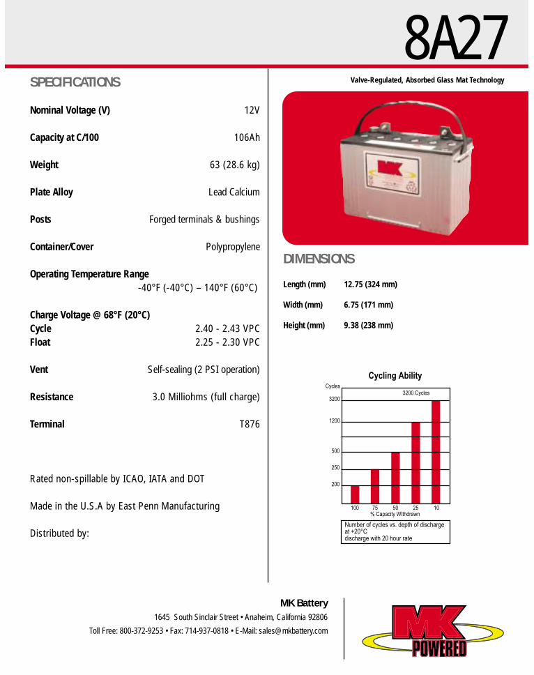
8A27
MK Battery1645 South Sinclair Street • Anaheim, California 92806
Toll Free: 800-372-9253 • Fax: 714-937-0818 • E-Mail: [email protected]
Valve-Regulated, Absorbed Glass Mat Technology
100% Capacity WIthdrawn
Number of cycles vs. depth of dischargeat +20°Cdischarge with 20 hour rate
75
200
250
500
1200
3200
Cycles3200 Cycles
50 25 10
Cycling Ability
Length (mm) 12.75 (324 mm)
Width (mm) 6.75 (171 mm)
Height (mm) 9.38 (238 mm)
Nominal Voltage (V) 12V
Capacity at C/100 106Ah
Weight 63 (28.6 kg)
Plate Alloy Lead Calcium
Posts Forged terminals & bushings
Container/Cover Polypropylene
Operating Temperature Range-40°F (-40°C) – 140°F (60°C)
Charge Voltage @ 68°F (20°C)Cycle 2.40 - 2.43 VPCFloat 2.25 - 2.30 VPC
Vent Self-sealing (2 PSI operation)
Resistance 3.0 Milliohms (full charge)
Terminal T876
Rated non-spillable by ICAO, IATA and DOT
Made in the U.S.A by East Penn Manufacturing
Distributed by:
SPECIFICATIONS
DIMENSIONS


Atlantic Solar Products, Inc., offers the following Concorde Batteries:
MAINTENANCE-FREE, VALVE-REGULATED, SEALED LEAD-ACID BATTERIES
DESIGNED FOR DEEP CYCLE / BACK-UP POWER PHOTOVOLTAIC APPLICATIONS
SPECIFICATIONS
Click Here For Battery Service Instructions
Part Number Volts
Overall DimensionsUnit Wt lbs (kg)
Nominal Capacity Ampere Hours @
L in (mm)
W in (mm)
H in (mm)
8 Hr Rate
24 Hr Rate
48 Hr Rate
120 Hr Rate
PVX -340T 12 7.71 (196) 5.18 (132) 6.89 (175) 25 (11.4) 30 34 36 38
PVX -420T 12 7.71 (196) 5.18 (132) 8.05 (204) 30 (13.6) 36 42 43 45
PVX -490T 12 8.99 (228) 5.45 (138) 8.82 (224) 36 (16.4) 43 49 52 55
PVX -560T 12 8.99 (228) 5.45 (138) 8.82 (224) 40 (18.2) 49 56 60 63
PVX -690T 12 10.22 (260) 6.60 (168) 8.93 (227) 51 (23.2) 60 69 73 79
PVX -840T 12 10.22 (260) 6.60 (168) 8.93 (227) 57 (25.9) 74 84 90 97
PVX-1080T 12 12.90 (328) 6.75 (172) 8.96 (228) 70 (31.8) 97 108 118 126
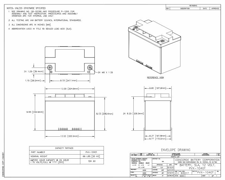
PVX-1040T 12 12.03 (306) 6.77 (172) 8.93 (227) 66 (30.0) 93 104 112 120
PVX -890T 12 12.90 (328) 6.75 (172) 8.96 (228) 62 (28.2) 79 89 95 102
PVX-2120L 12 20.75 (528) 8.71 (222) 10.42 (265) 138 (62.7) 194 212 235 253
PVX-2580L 12 20.76 (527) 10.89 (277) 9.65 (245) 165 (75) 236 258 285 305
PVX -1040HT 12 12.03 (306) 6.77 (172) 8.93 (227) 66 (30.0) 93 104 112 120
PVX-1380T 6 10.22 (260) 6.77 (172) 8.92 (227) 51 (23.2) 120 138 146 158
PVX-1680T 6 10.22 (260) 6.77 (172) 8.92 (227) 57 (25.9) 148 168 180 194
PVX-1780T 6 12.90 (328) 6.75 (171) 8.96 (228) 62 (28.2) 158 178 190 204
PVX-2080T 6 12.03 (306) 6.77 (172) 8.93 (227) 66 (30.0) 186 208 224 240
PVX-2160T 6 12.90 (328) 6.75 (171) 8.96 (228) 70 (31.8) 194 216 236 252
PVX-2240T 6 10.27 (261) 7.12 (181) 10.24 (260) 67 (30.4) 204 224 246 263
Standard Terminals: All "T" batteries now incorporate copper alloy M8 terminals except the PVX -340T & PVX-420T which are M6. All batteries supplied with silicon bronze bolts, nuts, and washers as required for installation. No exposed lead terminals. This change was made to improve environmental safety and health. Optional Terminals: L Blade or Automotive post type terminals are available installed by adding the appropriate suffix: "L"
Page 1 of 2Concorde Batteries - Atlantic Solar Products, Inc.
10/27/2003

for L Blade or "A" for automotive post. Handles: All part numbers include lifting handles except the PVX-490T, PVX-560T, and PVX-2240L. Ratings: Capacity ratings are stated at 77F (25 C) to 1.75 volts per cell. Drawings: Click on the part number in the table above or contact the factory.
SUN-EXTENDER® BATTERY DESIGN FEATURES
? Copper Alloy Terminals for improved electrical connections. ? No exposed lead terminals. This change was incorporated to improve environmental safety and health. ? Threaded insert terminals are recessed to prevent short circuits across battery connections.1
? New cover is flat top design. No protruding or exposed vent valves.1 ? Built in lifting handles, except PVX-490T, PVX-560T, and PVX-2240L. ? Reinforced container walls to reduce bulging. ? High Impact Strength Copolymer Polypropylene Case and Cover. ? Completely Sealed Valve Regulated Construction. ? Immobilized Electrolyte Non-Spillable. ? Maintenance Free Design Never Requires Watering. ? Absorbed Glass Mat (AGM) Micro-porous Glass Separators retain electrolyte. ? Flame Arresting Pressure Regulated Safety Valves. ? UL Recognized Systems Component. ? Positive Plates - Proprietary Lead Calcium Alloy- Negatives Plates - Lead Calcium. ? Low Self Discharge Rate Approximately 1 % per month at 25 C (77 F). ? Operate over a Wide Range of Temperatures from -40 C (-40 F) to +72 C (+160 F). ? Classified as "Non-Spillable Battery" for Transport. ? Most Part Numbers comply with DOT HMR49, Non-Hazardous Materials.
1 Threaded Insert "T" type Features.
CHARGING INSTRUCTIONS Initial charge or recharge: 2.37 to 2.40 volts per cell at 25 C (77 F). Float charge: 2.23 volts per cell at 25 C (77
F). Equalize charge: 2.40 volts per cell at 25 C (77 F). Temperature compensation = ±3.75 mV. per cell per degree C [Reference to 25 C (77 F)]. This is for battery temperature (not ambient temperature) and is useful for battery temperatures from O C (32 F) to 40 C (104 F). Contact Concorde Battery Corporation for temperatures
that exceed this range.
Specifications subject to change without notice.
Copyright © 2003, Atlantic Solar Products, Inc.
Page 2 of 2Concorde Batteries - Atlantic Solar Products, Inc.
10/27/2003

Atlantic Solar Products 9351-J Philadelphia Rd., P.O. Box 70060, Baltimore, MD 21237-6060 Phone 410-686-2500 Fax 410-686-6221
BE 26208 Battery EnclosureFits up to two 105Ah Batteries end to end
Mounts on 2”- 4” Schedule 40 Pole16” Centers
For larger poles use pipe strapping w/Optional Adapter

Sweeping Pulse Technology Every year millions of lead-acid batteries are prematurely discarded. Sulfation is the leading cause of these disposals and is the most destructive process determining the life of lead-acid batteries. Eight out of ten batteries are discarded as "dead", yet only suffer from this costly problem, a problem that can now be fully reversed and completely prevented.
During the normal discharge of a lead-acid battery, lead sulfate forms on the battery's plates. When recharged, this soft spongy material is converted back into the battery's electrolyte solution. When this material fails to release from the battery's plates, it begins to harden and crystallize. This destructive process is known as sulfation. Equalizing or over charging the battery was the only way, in the past, to remove the sulfation from the battery's plates. The very material that enables lead-acid batteries to release their energy and its out dated cure is what causes most batteries to fail.
Using Sweeping Pulse Technology will enable weak and dead batteries to provide a longer service life.
WHAT IS SWEEPING PULSE TECHNOLOGY?
Sweeping Pulse Technology is a patented, variable frequency, variable boost voltage process guaranteed to dissolve sulfate crystals back into the battery's electrolyte solution. All lead-acid batteries are adversely affected by the buildup of these deposits. As they collect on battery plates they restrict the flow of electrons and "lock away" active material required for normal operation. As this barrier becomes thicker and thicker, the battery's ability to accept a charge or deliver energy is drastically diminished, resulting in the perception that the battery is no longer usable.
Sweeping Pulse Technology allows the user to electronically dissolve sulfation formations back into the electrolyte solution without taking the battery out of service. Most importantly, if a new battery is equipped with Sweeping Pulse Technology it will always remain free and clean of sulfate crystals allowing it to operate unhampered at full capacity. This remarkable process generates no heat and can in no way harm the battery itself.
BENEFITS OF SWEEPING PULSE TECHNOLOGY
The principal benefit of Sweeping Pulse Technology is that it prevents the buildup of sulfate crystals on battery plates. Eliminating the number one cause of battery failure,
Page 1 of 3DeSulfator - Atlantic Solar Products, Inc.
10/27/2003

Sweeping Pulse Technology will significantly extend battery life.
Since the amount of exposed active plate surface is critical for determining battery output, a battery with clean plates and an unimpeded flow of electrons will accept a full charge and release all of its stored energy. Use of this leading edge technology will maintain battery efficiency.
Sweeping Pulse Technology can save money by reversing the capacity robbing effects of existing sulfation on batteries already in use and save even more by reducing man hours performing routine battery maintenance. Continual use of this technology will reduce battery disposal volumes, increase equipment readiness, and allow long term storage of batteries in a usable condition.
Whether you're a vehicle fleet manager, a solar system owner, or just a weekend marine enthusiast, use of Sweeping Pulse Technology will provide battery owners alike with these wide ranging benefits.
? Revert existing sulfate deposits ? Increase battery efficiency ? Prevent future sulfation ? Eliminate harmful overcharging ? Extend battery life ? Reduce hazardous material
disposal ? Eliminate battery capacity loss ? Equalize battery using no heat
? Increase battery dependability ? Quicker recharge times ? Offset battery self discharge ? Increase freeze protection ? Reduce routine battery
maintenance ? Decrease internal resistance ? Allow for long term battery storage ? Eliminate erroneous replacement
Model Number Description
DS-500
Self-powered conditioner suitable for any type of battery set that is regularly recharged. The unit can be attached to the battery or the charging source output. Unit consumes only 4.8 watts a day. Specify unit voltage when ordering, 12, 24, 36, 48 or 72 volts. Up to 350 Amps Hours.
DS-1000
High output, self-powered conditioner suitable for any type of battery set (with battery capacities higher than 350 amp hours) that is regularly recharged. The unit can be attached to the battery or the charging source output. Unit consumes only 9.6 watts a day. Specify voltage when ordering, 12, 24, 36, or 48 volts. Up to 1000 Amp Hours.
T-360
AC powered, portable unit with heavy duty battery clips; maximum power 200 milliamps. Standard 120V input. 220V, 50Hz export unit available Suitable for RV's, fishing and sport boats.
DP-5000 120 volt AC input; up to 600 volts output. Suitable for high capacity battery banks.(220V, 50Hz export unit available)
S-100 12 volt solar powered conditioner/trickle charger. 1 watt solar charger will maintain up to 100 amp hours of battery capacity.Solar powered conditioner/trickle charger. 2.8 watt solar charger will maintain up to 180 amp hours of battery
Page 2 of 3DeSulfator - Atlantic Solar Products, Inc.
10/27/2003

S-280 capacity. Works with 12, 24 & 36 volt battery sets. Suitable or all mobile equipment.
S-550 Solar powered conditioner/trickle charger. 5.5 watt solar charger will maintain up to 360 amp hours of battery capacity. Works with 12 volt battery sets.
S-1000 Solar powered conditioner/charger. 10 watt solar charger will produce an average of 2.3 amp hours per day, maintaining up to 690 amp hours of battery capacity.
VC-4 High output solar charger. 10 watt, 12 volt solar charger will produce an average of 3.76 amp hours per day.
VC-5 High output solar charger. 10 watt, 24 volt solar charger will produce an average of 1.88 amp hours per day.
Copyright © 2003, Atlantic Solar Products, Inc.
Page 3 of 3DeSulfator - Atlantic Solar Products, Inc.
10/27/2003