syllabus for b. tech. electrical engineering b.tech...
TRANSCRIPT
Dr. A.P.J. Abdul Kalam Technical UniversityUttar
Pradesh,Lucknow
Syllabus
for
B. Tech. Electrical Engineering
B.Tech. Electrical & Electronics Engg.
Third Year
(Effective from the Session: 2018-19)
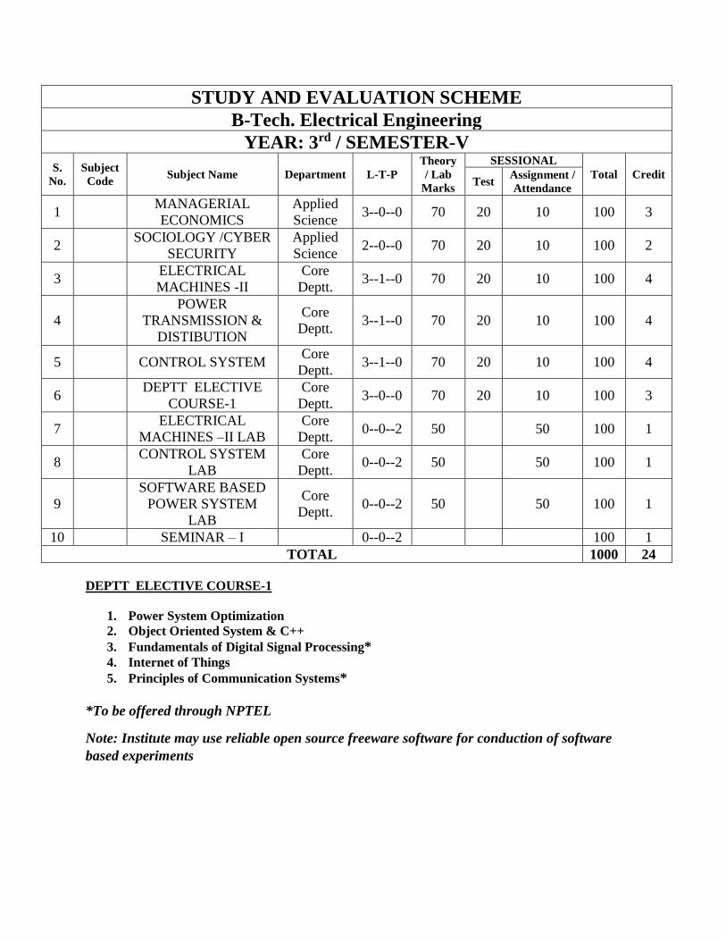
STUDY AND EVALUATION SCHEME
B-Tech. Electrical Engineering
YEAR: 3rd / SEMESTER-V
S.
No.
Subject
Code Subject Name Department L-T-P
Theory
/ Lab
Marks
SESSIONAL
Total Credit Test
Assignment /
Attendance
1 MANAGERIAL
ECONOMICS
Applied
Science 3--0--0 70 20 10 100 3
2 SOCIOLOGY /CYBER
SECURITY
Applied
Science 2--0--0 70 20 10 100 2
3 ELECTRICAL
MACHINES -II
Core
Deptt. 3--1--0 70 20 10 100 4
4
POWER
TRANSMISSION &
DISTIBUTION
Core
Deptt. 3--1--0 70 20 10 100 4
5 CONTROL SYSTEM Core
Deptt. 3--1--0 70 20 10 100 4
6 DEPTT ELECTIVE
COURSE-1
Core
Deptt. 3--0--0 70 20 10 100 3
7 ELECTRICAL
MACHINES –II LAB
Core
Deptt. 0--0--2 50 50 100 1
8 CONTROL SYSTEM
LAB
Core
Deptt. 0--0--2 50 50 100 1
9
SOFTWARE BASED
POWER SYSTEM
LAB
Core
Deptt. 0--0--2 50 50 100 1
10 SEMINAR – I 0--0--2 100 1
TOTAL 1000 24
DEPTT ELECTIVE COURSE-1
1. Power System Optimization
2. Object Oriented System & C++
3. Fundamentals of Digital Signal Processing*
4. Internet of Things
5. Principles of Communication Systems*
*To be offered through NPTEL
Note: Institute may use reliable open source freeware software for conduction of software
based experiments
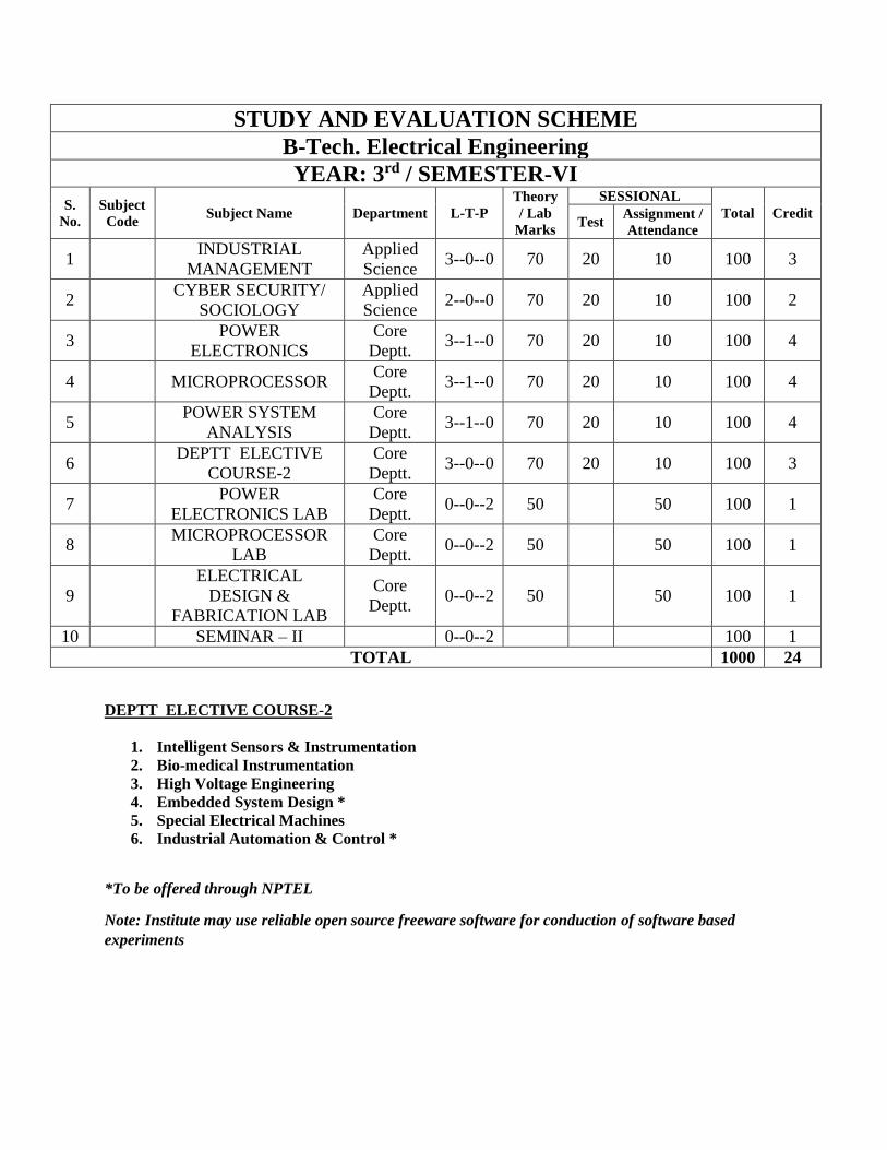
STUDY AND EVALUATION SCHEME
B-Tech. Electrical Engineering
YEAR: 3rd / SEMESTER-VI
S.
No.
Subject
Code Subject Name Department L-T-P
Theory
/ Lab
Marks
SESSIONAL
Total Credit Test
Assignment /
Attendance
1 INDUSTRIAL
MANAGEMENT
Applied
Science 3--0--0 70 20 10 100 3
2 CYBER SECURITY/
SOCIOLOGY
Applied
Science 2--0--0 70 20 10 100 2
3 POWER
ELECTRONICS
Core
Deptt. 3--1--0 70 20 10 100 4
4 MICROPROCESSOR Core
Deptt. 3--1--0 70 20 10 100 4
5 POWER SYSTEM
ANALYSIS
Core
Deptt. 3--1--0 70 20 10 100 4
6 DEPTT ELECTIVE
COURSE-2
Core
Deptt. 3--0--0 70 20 10 100 3
7 POWER
ELECTRONICS LAB
Core
Deptt. 0--0--2 50 50 100 1
8 MICROPROCESSOR
LAB
Core
Deptt. 0--0--2 50 50 100 1
9
ELECTRICAL
DESIGN &
FABRICATION LAB
Core
Deptt. 0--0--2 50 50 100 1
10 SEMINAR – II 0--0--2 100 1
TOTAL 1000 24
DEPTT ELECTIVE COURSE-2
1. Intelligent Sensors & Instrumentation
2. Bio-medical Instrumentation
3. High Voltage Engineering
4. Embedded System Design *
5. Special Electrical Machines
6. Industrial Automation & Control *
*To be offered through NPTEL
Note: Institute may use reliable open source freeware software for conduction of software based
experiments
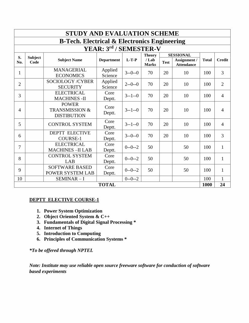
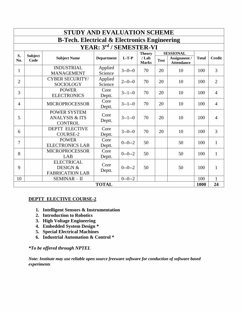
STUDY AND EVALUATION SCHEME
B-Tech. Electrical & Electronics Engineering
YEAR: 3rd / SEMESTER-V
S.
No.
Subject
Code Subject Name Department L-T-P
Theory
/ Lab
Marks
SESSIONAL
Total Credit Test
Assignment /
Attendance
1 MANAGERIAL
ECONOMICS
Applied
Science 3--0--0 70 20 10 100 3
2 SOCIOLOGY /CYBER
SECURITY
Applied
Science 2--0--0 70 20 10 100 2
3 ELECTRICAL
MACHINES -II
Core
Deptt. 3--1--0 70 20 10 100 4
4
POWER
TRANSMISSION &
DISTIBUTION
Core
Deptt. 3--1--0 70 20 10 100 4
5 CONTROL SYSTEM Core
Deptt. 3--1--0 70 20 10 100 4
6 DEPTT ELECTIVE
COURSE-1
Core
Deptt. 3--0--0 70 20 10 100 3
7 ELECTRICAL
MACHINES –II LAB
Core
Deptt. 0--0--2 50 50 100 1
8 CONTROL SYSTEM
LAB
Core
Deptt. 0--0--2 50 50 100 1
9 SOFTWARE BASED
POWER SYSTEM LAB
Core
Deptt. 0--0--2 50 50 100 1
10 SEMINAR – I 0--0--2 100 1
TOTAL 1000 24
DEPTT ELECTIVE COURSE-1
1. Power System Optimization
2. Object Oriented System & C++
3. Fundamentals of Digital Signal Processing *
4. Internet of Things
5. Introduction to Computing
6. Principles of Communication Systems *
*To be offered through NPTEL
Note: Institute may use reliable open source freeware software for conduction of software
based experiments
STUDY AND EVALUATION SCHEME
B-Tech. Electrical & Electronics Engineering
YEAR: 3rd / SEMESTER-VI
S.
No.
Subject
Code Subject Name Department L-T-P
Theory
/ Lab
Marks
SESSIONAL
Total Credit Test
Assignment /
Attendance
1 INDUSTRIAL
MANAGEMENT
Applied
Science 3--0--0 70 20 10 100 3
2 CYBER SECURITY/
SOCIOLOGY
Applied
Science 2--0--0 70 20 10 100 2
3 POWER
ELECTRONICS
Core
Deptt. 3--1--0 70 20 10 100 4
4 MICROPROCESSOR Core
Deptt. 3--1--0 70 20 10 100 4
5
POWER SYSTEM
ANALYSIS & ITS
CONTROL
Core
Deptt. 3--1--0 70 20 10 100 4
6 DEPTT ELECTIVE
COURSE-2
Core
Deptt. 3--0--0 70 20 10 100 3
7 POWER
ELECTRONICS LAB
Core
Deptt. 0--0--2 50 50 100 1
8 MICROPROCESSOR
LAB
Core
Deptt. 0--0--2 50 50 100 1
9
ELECTRICAL
DESIGN &
FABRICATION LAB
Core
Deptt. 0--0--2 50 50 100 1
10 SEMINAR – II 0--0--2 100 1
TOTAL 1000 24
DEPTT ELECTIVE COURSE-2
1. Intelligent Sensors & Instrumentation
2. Introduction to Robotics
3. High Voltage Engineering
4. Embedded System Design *
5. Special Electrical Machines
6. Industrial Automation & Control *
*To be offered through NPTEL
Note: Institute may use reliable open source freeware software for conduction of software based
experiments
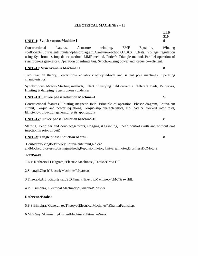
ELECTRICAL MACHINES – II
LTP
310
UNIT–I: Synchronous Machine I 9
Constructional features, Armature winding, EMF Equation, Winding
coefficients,Equivalentcircuitandphasordiagram,Armaturereaction,O.C.&S. C.tests, Voltage regulation
using Synchronous Impedance method, MMF method, Potier's Triangle method, Parallel operation of
synchronous generators, Operation on infinite bus, Synchronizing power and torque co-efficient.
UNIT–II: Synchronous Machine II 8
Two reaction theory, Power flow equations of cylindrical and salient pole machines, Operating
characteristics.
Synchronous Motor- Starting methods, Effect of varying field current at different loads, V- curves,
Hunting & damping, Synchronous condenser.
UNIT–III: Three phaseInduction Machine–I 9
Constructional features, Rotating magnetic field, Principle of operation, Phasor diagram, Equivalent
circuit, Torque and power equations, Torque-slip characteristics, No load & blocked rotor tests,
Efficiency, Induction generator & its applications
UNIT–IV: Three phase Induction Machine-II 8
Starting, Deep bar and doublecagerotors, Cogging &Crawling, Speed control (with and without emf
injection in rotor circuit)
UNIT–V: Single phase Induction Motor 8
Doublerevolvingfieldtheory,Equivalentcircuit,Noload
andblockedrotortests,Startingmethods,Repulsionmotor, Universalmotor,BrushlessDCMotors
TextBooks:
1.D.P.Kothari&I.J.Nagrath,"Electric Machines", TataMcGraw Hill
2.SmarajitGhosh"ElectricMachines",Pearson
3.Fitzerald,A.E.,KingsleyandS.D.Umans"ElectricMachinery",MCGrawHill.
4.P.S.Bimbhra,"Electrical Machinery",KhannaPublisher
ReferenceBooks:
5.P.S.Bimbhra,"GeneralizedTheoryofElectricalMachines",KhannaPublishers
6.M.G.Say,"AlternatingCurrentMachines",Pitman&Sons

POWER TRANSMISSON & DISTRIBUTION
L T P
3 1 0
Unit – I: Power System Components:
Single line diagram of Power system,
Brief description of power system Elements: Synchronous machine, transformer, transmission line, bus
bar, circuit breaker and isolator.
Supply System: Different kinds of supply system and their comparison, choice of transmission voltage.
Transmission Lines:
Configurations, types of conductors, resistance of line, skin effect, Kelvin’s law, Proximity effect.
Unit – II: Over Head Transmission Lines
Calculation of inductance and capacitance of single phase, three phase, single circuit and double circuit
transmission lines
Representation and performance of short, medium and long transmission lines, Ferranti effect, Surge
impedance loading.
Unit – III: Corona and Interference:
Phenomenon of corona, corona formation, calculation of potential gradient, corona loss, factors affecting
corona, methods of reducing corona and interference
Electrostatic and electromagnetic interference with communication lines.
Overhead line Insulators:
Type of insulators and their applications, potential distribution over a string of insulators, methods of
equalizing the potential, string efficiency.
Unit – IV: Mechanical Design of transmission line:
Catenary curve, calculation of sag & tension, effects of wind and ice loading, sag template, vibration
dampers.
Insulated cables:
Type of cables and their construction, dielectric stress, grading of cables, insulation resistance,
capacitance of single phase and three phase cables, dielectric loss, heating of cables.
Unit – V: Neutral grounding:
Necessity of neutral grounding, various methods of neutral grounding, earthing transformer, grounding
practices.
Distribution Systems:
Distribution system layout, Introduction of Distribution System, Primary & Secondary distribution,
Design consideration, distribution system losses, Classification of Distributed system- Radial Ring
interconnected systems, Stepped distribution.
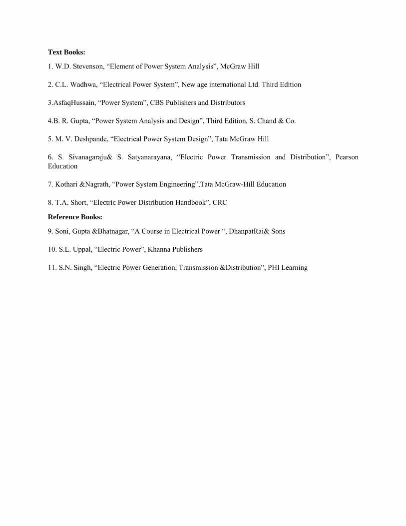
Text Books:
1. W.D. Stevenson, “Element of Power System Analysis”, McGraw Hill
2. C.L. Wadhwa, “Electrical Power System”, New age international Ltd. Third Edition
3.AsfaqHussain, “Power System”, CBS Publishers and Distributors
4.B. R. Gupta, “Power System Analysis and Design”, Third Edition, S. Chand & Co.
5. M. V. Deshpande, “Electrical Power System Design”, Tata McGraw Hill
6. S. Sivanagaraju& S. Satyanarayana, “Electric Power Transmission and Distribution”, Pearson
Education
7. Kothari &Nagrath, “Power System Engineering”,Tata McGraw-Hill Education
8. T.A. Short, “Electric Power Distribution Handbook”, CRC
Reference Books:
9. Soni, Gupta &Bhatnagar, “A Course in Electrical Power “, DhanpatRai& Sons
10. S.L. Uppal, “Electric Power”, Khanna Publishers
11. S.N. Singh, “Electric Power Generation, Transmission &Distribution”, PHI Learning
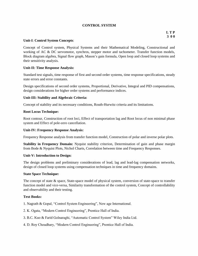
CONTROL SYSTEM
L T P
3 0 0
Unit-I: Control System Concepts:
Concept of Control system, Physical Systems and their Mathematical Modeling, Constructional and
working of AC & DC servomotor, synchros, stepper motor and tachometer. Transfer function models,
Block diagram algebra, Signal flow graph, Mason’s gain formula, Open loop and closed loop systems and
their sensitivity analysis.
Unit-II: Time Response Analysis:
Standard test signals, time response of first and second order systems, time response specifications, steady
state errors and error constants.
Design specifications of second order systems, Proportional, Derivative, Integral and PID compensations,
design considerations for higher order systems and performance indices.
Unit-III: Stability and Algebraic Criteria:
Concept of stability and its necessary conditions, Routh-Hurwitz criteria and its limitations.
Root Locus Technique:
Root contour, Construction of root loci, Effect of transportation lag and Root locus of non minimal phase
system and Effect of pole-zero cancellation.
Unit-IV: Frequency Response Analysis:
Frequency Response analysis from transfer function model, Construction of polar and inverse polar plots.
Stability in Frequency Domain: Nyquist stability criterion, Determination of gain and phase margin
from Bode & Nyquist Plots, Nichol Charts, Correlation between time and Frequency Responses.
Unit-V: Introduction to Design:
The design problems and preliminary considerations of lead, lag and lead-lag compensation networks,
design of closed loop systems using compensation techniques in time and frequency domains.
State Space Technique:
The concept of state & space, State-space model of physical system, conversion of state-space to transfer
function model and vice-versa, Similarity transformation of the control system, Concept of controllability
and observability and their testing.
Text Books:
1. Nagrath & Gopal, “Control System Engineering”, New age International.
2. K. Ogata, “Modern Control Engineering”, Prentice Hall of India.
3. B.C. Kuo & Farid Golnaraghi, “Automatic Control System” Wiley India Ltd.
4. D. Roy Choudhary, “Modern Control Engineering”, Prentice Hall of India.
Reference Books:
5. Norman S. Mise, Control System Engineering , Wiley Publishing Co.
6. Ajit K Mandal, “Introduction to Control Engineering” New Age International.
7. R.T. Stefani, B.Shahian, C.J.Savant and G.H. Hostetter, “Design of Feedback Control Systems” Oxford
University Press.
8. Samarjit Ghosh, “ Control Systems theory and Applications”, Pearson Education
ELECTRICAL MACHINES – II LABORATORY
L T P
0 0 2
Note: Minimum ten experiments are to be performed from the following list, out of which
there should be at least two software based experiments.
1. To perform no load and blocked rotor tests on a three phase squirrel cage induction motor and
determine equivalent circuit.
2. To perform load test on a three phase induction motor and draw Torque -speed characteristics
3. To perform no load and blocked rotor tests on a single phase induction motor and determine equivalent
circuit.
4. To study speed control of three phase induction motor by varying supply voltage and by keeping V/f
ratio constant.
5. To perform open circuit and short circuit tests on a three phase alternator and determine voltage
regulation at full load and at unity, 0.8 lagging and leading power factors by (i) EMF method (ii) MMF
method.
6. To determine V-curves and inverted V-curves of a three phase synchronous motor.
7. To determine Xd and Xq of a three phase salient pole synchronous machine using the slip test and to
draw the power-angle curve.
8. To study synchronization of an alternator with the infinite bus by using: (i) dark lamp method (ii) two
bright and one dark lamp method.
9. To determine speed-torque characteristics of three phase slip ring induction motor and study the effect
of including resistance, or capacitance in the rotor circuit.
10.To determine speed-torque characteristics of single phase induction motor and study the effect of
voltage variation.
11. To determine speed-torque characteristics of a three phase induction motor by (i) keeping v/f ratio
constant (ii) increasing frequency at the rated voltage.
12. To draw O.C. and S.C. characteristics of a three phase alternator from the experimental data and
determine voltage regulation at full load, and unity, 0.8 lagging and leading power factors.
13. To determine steady state performance of a three phase induction motor using equivalent circuit.
*For Software based experiments (Develop Computer Program in ‘C’ language or use
MATLAB or Equivalent open source freeware software)
CONTROL SYSTEM LABORATORY
L T P
0 0 2
Note: The minimum of 10 experiments are to be performed from the following, out of which at least
three should be software based.
1. To determine response of first order and second order systems for step input for various
values of constant ’K’ using linear simulator unit and compare theoretical and practical
results.
2. To study P, PI and PID temperature controller for an oven and compare their performance.
3. To study and calibrate temperature using resistance temperature detector (RTD)
4. To design Lag, Lead and Lag-Lead compensators using Bode plot.
5. To study DC position control system
6. To study synchro-transmitter and receiver and obtain output vs input characteristics
7. To determine speed-torque characteristics of an ac servomotor.
8. To study performance of servo voltage stabilizer at various loads using load bank.
9. To study behavior of separately excited dc motor in open loop and closed loop conditions atvarious
loads.
10. To study characteristics of positional error detector by angular displacement of two servo potentio-
meters.
Software based experiments (Use MATLAB, LABVIEW etc. or equivalent open source freeware
software like Scilab)
11. To simulate PID controller for transportation lag.
12. To determine time domain response of a second order system for step input and obtain
performance parameters.
13. To convert transfer function of a system into state space form and vice-versa.
14. To plot root locus diagram of an open loop transfer function and determine range of gain ‘k’
fir stability.
15. To plot a Bode diagram of an open loop transfer function.
16. To draw a Nyquist plot of an open loop transfers functions and examine the stability of the
closed loop system.
Reference Books:
1. K.Ogata,“Modern Control Engineering” Prentice Hall of India.
2. Norman S.Nise, “Control System Engineering”, John Wiley & Sons.
3. M.Gopal, “Control Systems: Principles & Design” Tata McGraw Hill.
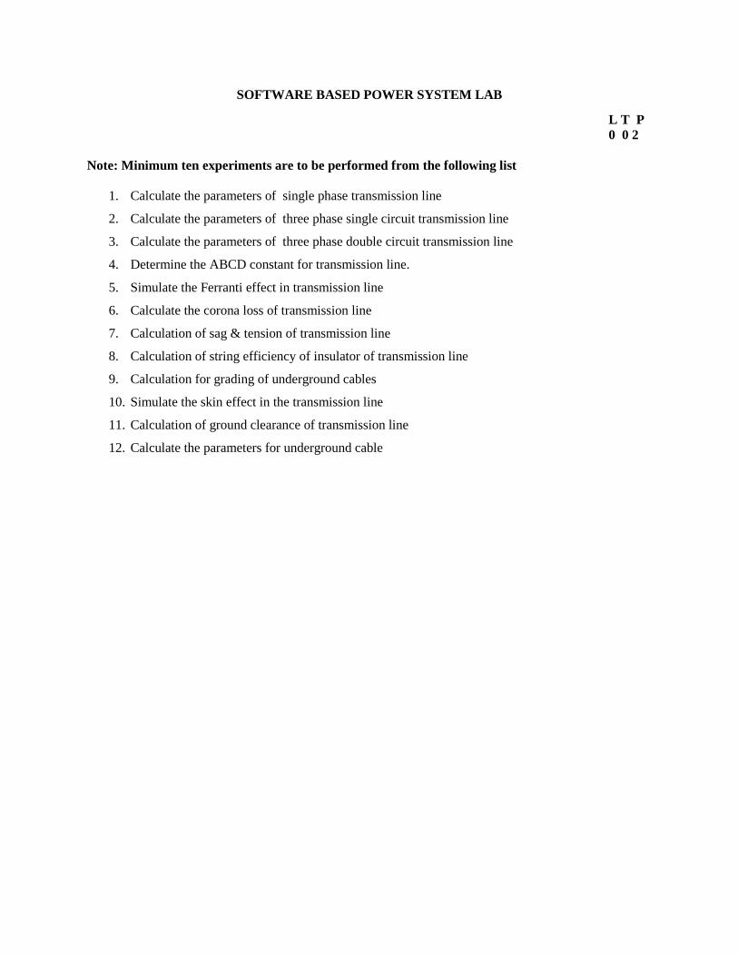
SOFTWARE BASED POWER SYSTEM LAB
L T P
0 0 2
Note: Minimum ten experiments are to be performed from the following list
1. Calculate the parameters of single phase transmission line
2. Calculate the parameters of three phase single circuit transmission line
3. Calculate the parameters of three phase double circuit transmission line
4. Determine the ABCD constant for transmission line.
5. Simulate the Ferranti effect in transmission line
6. Calculate the corona loss of transmission line
7. Calculation of sag & tension of transmission line
8. Calculation of string efficiency of insulator of transmission line
9. Calculation for grading of underground cables
10. Simulate the skin effect in the transmission line
11. Calculation of ground clearance of transmission line
12. Calculate the parameters for underground cable
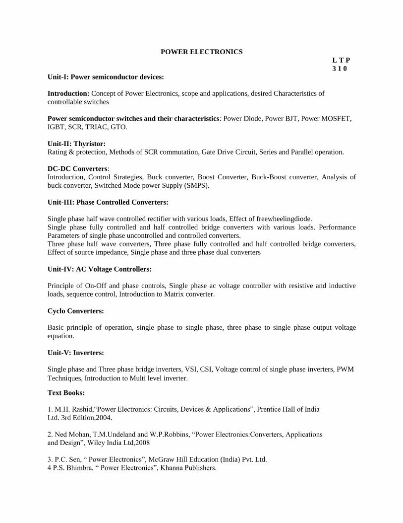
POWER ELECTRONICS
L T P
3 1 0
Unit-I: Power semiconductor devices:
Introduction: Concept of Power Electronics, scope and applications, desired Characteristics of
controllable switches
Power semiconductor switches and their characteristics: Power Diode, Power BJT, Power MOSFET,
IGBT, SCR, TRIAC, GTO.
Unit-II: Thyristor: Rating & protection, Methods of SCR commutation, Gate Drive Circuit, Series and Parallel operation.
DC-DC Converters:
Introduction, Control Strategies, Buck converter, Boost Converter, Buck-Boost converter, Analysis of
buck converter, Switched Mode power Supply (SMPS).
Unit-III: Phase Controlled Converters:
Single phase half wave controlled rectifier with various loads, Effect of freewheelingdiode.
Single phase fully controlled and half controlled bridge converters with various loads. Performance
Parameters of single phase uncontrolled and controlled converters.
Three phase half wave converters, Three phase fully controlled and half controlled bridge converters,
Effect of source impedance, Single phase and three phase dual converters
Unit-IV: AC Voltage Controllers:
Principle of On-Off and phase controls, Single phase ac voltage controller with resistive and inductive
loads, sequence control, Introduction to Matrix converter.
Cyclo Converters:
Basic principle of operation, single phase to single phase, three phase to single phase output voltage
equation.
Unit-V: Inverters:
Single phase and Three phase bridge inverters, VSI, CSI, Voltage control of single phase inverters, PWM
Techniques, Introduction to Multi level inverter.
Text Books:
1. M.H. Rashid,“Power Electronics: Circuits, Devices & Applications”, Prentice Hall of India
Ltd. 3rd Edition,2004.
2. Ned Mohan, T.M.Undeland and W.P.Robbins, “Power Electronics:Converters, Applications
and Design”, Wiley India Ltd,2008
3. P.C. Sen, “ Power Electronics”, McGraw Hill Education (India) Pvt. Ltd.
4 P.S. Bhimbra, “ Power Electronics”, Khanna Publishers.
Reference Books:
5. M.S. Jamil Asghar, “Power Electronics” Prentice Hall of India Ltd., 2004
6. Chakrabarti&Rai, “Fundamentals of Power Electronics &Drives”DhanpatRai& Sons.
7. V.R. Moorthy, “ Power Electronics : Devices, Circuits and Industrial Applications” Oxford
University Press,2007
8. S.N.Singh, “A Text Book of Power Electronics” DhanpatRai& Sons
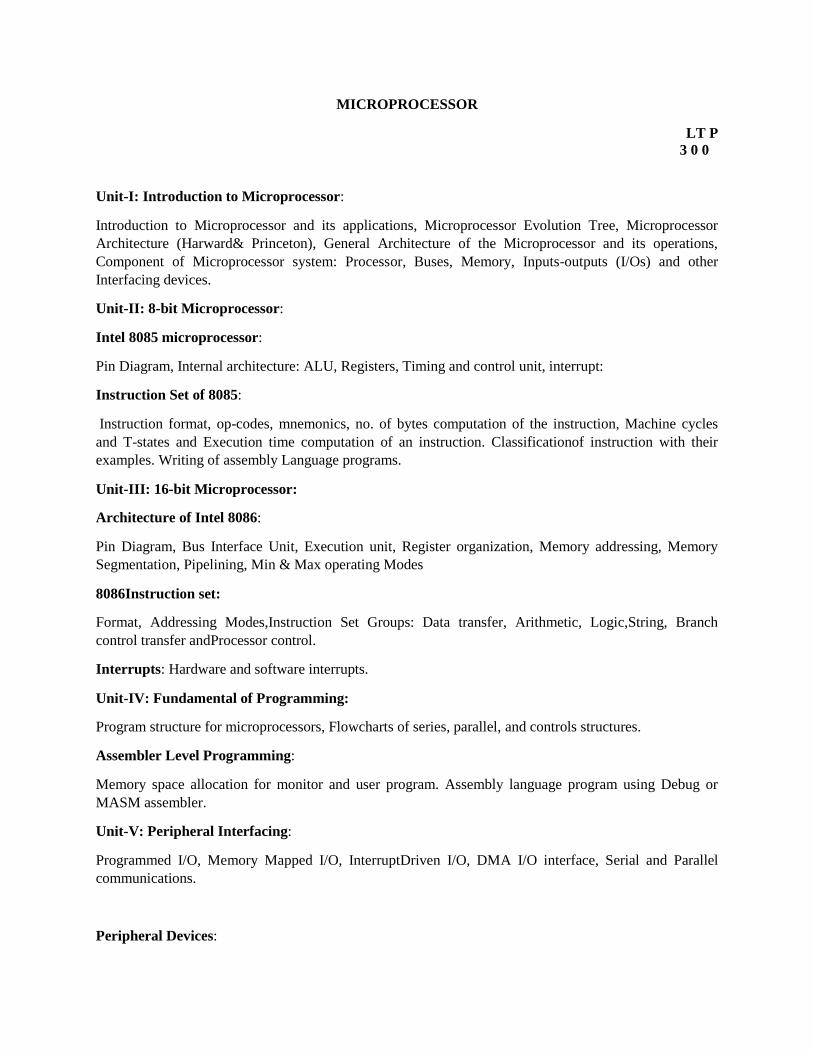
MICROPROCESSOR
LT P
3 0 0
Unit-I: Introduction to Microprocessor:
Introduction to Microprocessor and its applications, Microprocessor Evolution Tree, Microprocessor
Architecture (Harward& Princeton), General Architecture of the Microprocessor and its operations,
Component of Microprocessor system: Processor, Buses, Memory, Inputs-outputs (I/Os) and other
Interfacing devices.
Unit-II: 8-bit Microprocessor:
Intel 8085 microprocessor:
Pin Diagram, Internal architecture: ALU, Registers, Timing and control unit, interrupt:
Instruction Set of 8085:
Instruction format, op-codes, mnemonics, no. of bytes computation of the instruction, Machine cycles
and T-states and Execution time computation of an instruction. Classificationof instruction with their
examples. Writing of assembly Language programs.
Unit-III: 16-bit Microprocessor:
Architecture of Intel 8086:
Pin Diagram, Bus Interface Unit, Execution unit, Register organization, Memory addressing, Memory
Segmentation, Pipelining, Min & Max operating Modes
8086Instruction set:
Format, Addressing Modes,Instruction Set Groups: Data transfer, Arithmetic, Logic,String, Branch
control transfer andProcessor control.
Interrupts: Hardware and software interrupts.
Unit-IV: Fundamental of Programming:
Program structure for microprocessors, Flowcharts of series, parallel, and controls structures.
Assembler Level Programming:
Memory space allocation for monitor and user program. Assembly language program using Debug or
MASM assembler.
Unit-V: Peripheral Interfacing:
Programmed I/O, Memory Mapped I/O, InterruptDriven I/O, DMA I/O interface, Serial and Parallel
communications.
Peripheral Devices:
DMA controller (Intel 8237), Programmable peripheral interface (Intel 8255), Programmable
timer/counter (Intl 8253/8254),Programmable Interrupt Controller (Intel 8259).
Text Books:
1. Gaonkar, Ramesh S, “Microprocessor Architecture, programming and applications with the 8085”
Pen ram International Publishing 5th Ed.
2. Avtar Singh& Walter A. Triebel“8088 & 8086 Microprocessor” Pearson Education.
3. Ray, A.K. &Burchandi, K.M., “Advanced Microprocessors and Peripherals: Architecture,
Programaming and Interfacing” Tata Mc. Graw Hill.
Reference Books:
4. Brey, Barry B. “INTEL Microprocessors” Prentice Hall ( India)
5. Aditya P Mathur, “Introduction to Microprocessor” Tata McGraw Hill
6. M. Rafiquzzaman, “Microprocessors- Theory and applications” PHI
7. B. Ram, “Advanced Microprocessor & Interfacing” Tata McGraw Hill
8. Renu Singh &B.P.Singh, “Microprocessor and Interfacing and applications” New Age International
9. Liu and Gibson G.A., “Microcomputer Systems: The 8086/8088 Family” Prentice Hall (India)
POWER SYSTEM ANALYSIS
L T P
3 1 0
Unit-I: Representation of Power System Components:
Synchronous machines, Transformers, Transmission lines, One line diagram, Impedance and reactance
diagram, per unit system.
Symmetrical Components:
Symmetrical Components of unbalanced phasors, power in terms of symmetrical components, sequence
impedances and sequence networks.
Unit-II: Symmetrical Fault Analysis:
Transient if R-L series circuit, calculation of 3-phase short circuit current and reactance of Synchronous
machine, internal voltage of loaded machines under transient conditions.
Unsymmetrical Faults:
Analysis of single line to ground fault, line-to-line fault and Double Line to ground fault on an unloaded
generators and power system network with and without fault impedance.
Formation of Z bus using singular transformation and algorithm, computer method for short circuit
calculations.
Unit-III: Load Flows:
Introduction, bus classifications, nodal admittance matrix (YBUS), development of load flow equations,
load flow solution using Gauss Siedel and Newton-Raphson method, approximation to N-R method, line
flow equation sand fast decoupled method.
Unit-IV: Power System Stability:
Stability and Stability limit, Steady state stability study, derivation of Swing equation, transient stability
studies by equal area criterion and step-by-step method. Factors affecting steady state and transient
stability and methods of improvement.
Unit-V: Traveling Waves:
Wave Equation for uniform Transmission lines, velocity of propagation, surge impedance, reflection and
transmission of traveling waves under different line loadings. Bewlay’s lattice diagram, protection of
equipments and line against traveling waves.
Text Book:
1. W.D. Stevenson, Jr. “Elements of Power System Analysis”,McGraw Hill
2. C.L. Wadhwa, “Electrical Power System”, New Age International
3. Chakraborthy, Soni, Gupta &Bhatnagar, “Power System Engineering”, DhanpatRai& Co.
4. T.K. Nagsarkar& M.S. Sukhija, “Power System Analysis” Oxford University Press, 2007
Reference Books:
5. O.I. Elgerd, “Electric Energy System Theory” Tata McGraw Hill
6. Hadi Sadat, “Power System Analysis”, Tata McGraw Hill
7. D.Das, “Electrical Power Systems” New Age International
8. J.D. Glover, M. S. Sharma & T.J. Overbye, “Power System Analysis and Design” Thomson
9. P.S.R. Murthy “Power System Analysis” B.S. Publications.
10. Stagg and E1- Abiad, “Computer Methods in Power System Analysis” Tata McGraw Hill
11. Kothari &Nagrath, “Modern Power System Analysis” Tata McGraw Hill
12. A.J. wood, B.F. Wollenberg, ”Power Generation, Operation and Control” John Wiley & Sons

POWER ELECTRONICS LABORATORY
L T P
0 0 3
Note: The minimum of 10 experiments is to be performed out of which at least three should be
software based.
1. To study triggering of (i) IGBT (ii) MOSFET (iii) power transistor
2. To study V-I characteristics of SCR and measure latching and holding currents.
3. To compare the R, RC &UJT trigger circuit for SCR.
4. To study the commutation circuit for SCR.
5. To study single phase fully controlled bridge rectifiers with resistive and inductive loads.
6. To study single phase fully controlled bridge rectifiers with DC motor load.
7. To study three-phase fully controlled bridge rectifier with resistive and inductive loads.
8. To study single-phase ac voltage regulator with resistive and inductive loads.
9. To study single phase cyclo-converter
10. To study the four quadrant operation of chopper circuit
11. To study MOSFET/IGBT based single-phase bridge inverter.
Software based experiments (PSPICE/MATLAB or equivalent open source freeware software like
Scilab)
12. To obtain the simulation of single phase half wave controlled rectifier with R and RL load and plot
load voltage and load current waveforms.
13. To obtain simulation of single phase fully controlled bridge rectifier and plot load voltage
and load current waveform for inductive load.
14. To obtain simulation of single phase full wave ac voltage controller and draw load voltage andload
current waveforms for inductive load.
15. To obtain simulation of step down dc chopper with L-C output filter for inductive load and
determine steady-state values of output voltage ripples in output voltage and load current.
Text/Reference Books:
1. M.H.Rashid, “Power Electronics: Circuits, Devices and Applications”, 3rd Edition, prentice
Hall of India.
2. D.W. Hart, “Introduction to power Electronics” Prentice hall Inc.
MICROPROCESSOR LABORATORY
L T P
0 0 2
A. Study Experiments (any two):
1. To study 8085 based microprocessor system
2. To study 8086 and 8086A based microprocessor system
3. To study Pentium Processor
B. Programming based Experiments (any four):
4. To develop and run a program for finding out the largest/smallest number from a given set of
numbers.
5. To develop and run a program for arranging in ascending/descending order of a set of
Numbers
6. To perform multiplication/division of given numbers
7. To perform conversion of temperature from 0F to 0C and vice-versa
8. To perform computation of square root of a given number
9. To perform floating point mathematical operations (addition, subtraction, multiplication and
division)
C. Interfacing based Experiments (any four):
10. To obtain interfacing of RAM chip to 8085/8086 based system
11. To obtain interfacing of keyboard controller
12. To obtain interfacing of DMA controller
13. To obtain interfacing of PPI
14. To obtain interfacing of UART/USART
15. To perform microprocessor based stepper motor operation through 8085 kit
16. To perform microprocessor based traffic light control
17. To perform microprocessor based temperature control of hot water
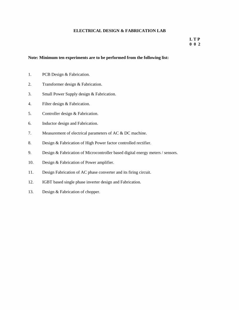
ELECTRICAL DESIGN & FABRICATION LAB
L T P
0 0 2
Note: Minimum ten experiments are to be performed from the following list:
1. PCB Design & Fabrication.
2. Transformer design & Fabrication.
3. Small Power Supply design & Fabrication.
4. Filter design & Fabrication.
5. Controller design & Fabrication.
6. Inductor design and Fabrication.
7. Measurement of electrical parameters of AC & DC machine.
8. Design & Fabrication of High Power factor controlled rectifier.
9. Design & Fabrication of Microcontroller based digital energy meters / sensors.
10. Design & Fabrication of Power amplifier.
11. Design Fabrication of AC phase converter and its firing circuit.
12. IGBT based single phase inverter design and Fabrication.
13. Design & Fabrication of chopper.
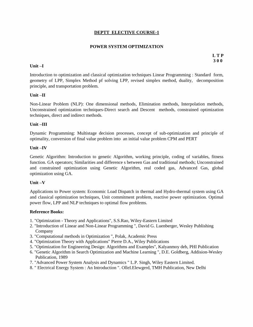
DEPTT ELECTIVE COURSE-1
POWER SYSTEM OPTIMIZATION
L T P
3 0 0
Unit –I
Introduction to optimization and classical optimization techniques Linear Programming : Standard form,
geometry of LPP, Simplex Method pf solving LPP, revised simplex method, duality, decomposition
principle, and transportation problem.
Unit –II
Non-Linear Problem (NLP): One dimensional methods, Elimination methods, Interpolation methods,
Unconstrained optimization techniques-Direct search and Descent methods, constrained optimization
techniques, direct and indirect methods.
Unit –III
Dynamic Programming: Multistage decision processes, concept of sub-optimization and principle of
optimality, conversion of final value problem into an initial value problem CPM and PERT
Unit –IV
Genetic Algorithm: Introduction to genetic Algorithm, working principle, coding of variables, fitness
function. GA operators; Similarities and difference s between Gas and traditional methods; Unconstrained
and constrained optimization using Genetic Algorithm, real coded gas, Advanced Gas, global
optimization using GA.
Unit –V
Applications to Power system: Economic Load Dispatch in thermal and Hydro-thermal system using GA
and classical optimization techniques, Unit commitment problem, reactive power optimization. Optimal
power flow, LPP and NLP techniques to optimal flow problems.
Reference Books:
1. "Optimization - Theory and Applications", S.S.Rao, Wiley-Eastern Limited
2. "Introduction of Linear and Non-Linear Programming ", David G. Luenberger, Wesley Publishing
Company
3. "Computational methods in Optimization ", Polak, Academic Press
4. "Optimization Theory with Applications" Pierre D.A., Wiley Publications
5. "Optimization for Engineering Design: Algorithms and Examples", Kalyanmoy deb, PHI Publication
6. "Genetic Algorithm in Search Optimization and Machine Learning ", D.E. Goldberg, Addision-Wesley
Publication, 1989
7. "Advanced Power System Analysis and Dynamics " L.P. Singh, Wiley Eastern Limited.
8. " Electrical Energy System : An Introduction ". OlleI.Elewgerd, TMH Publication, New Delhi
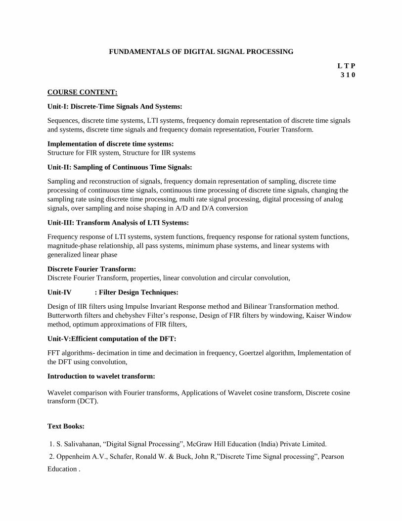
FUNDAMENTALS OF DIGITAL SIGNAL PROCESSING
L T P
3 1 0
COURSE CONTENT:
Unit-I: Discrete-Time Signals And Systems:
Sequences, discrete time systems, LTI systems, frequency domain representation of discrete time signals
and systems, discrete time signals and frequency domain representation, Fourier Transform.
Implementation of discrete time systems:
Structure for FIR system, Structure for IIR systems
Unit-II: Sampling of Continuous Time Signals:
Sampling and reconstruction of signals, frequency domain representation of sampling, discrete time
processing of continuous time signals, continuous time processing of discrete time signals, changing the
sampling rate using discrete time processing, multi rate signal processing, digital processing of analog
signals, over sampling and noise shaping in A/D and D/A conversion
Unit-III: Transform Analysis of LTI Systems:
Frequency response of LTI systems, system functions, frequency response for rational system functions,
magnitude-phase relationship, all pass systems, minimum phase systems, and linear systems with
generalized linear phase
Discrete Fourier Transform:
Discrete Fourier Transform, properties, linear convolution and circular convolution,
Unit-IV : Filter Design Techniques:
Design of IIR filters using Impulse Invariant Response method and Bilinear Transformation method.
Butterworth filters and chebyshev Filter’s response, Design of FIR filters by windowing, Kaiser Window
method, optimum approximations of FIR filters,
Unit-V:Efficient computation of the DFT:
FFT algorithms- decimation in time and decimation in frequency, Goertzel algorithm, Implementation of
the DFT using convolution,
Introduction to wavelet transform:
Wavelet comparison with Fourier transforms, Applications of Wavelet cosine transform, Discrete cosine
transform (DCT).
Text Books:
1. S. Salivahanan, “Digital Signal Processing”, McGraw Hill Education (India) Private Limited.
2. Oppenheim A.V., Schafer, Ronald W. & Buck, John R,”Discrete Time Signal processing”, Pearson
Education .
Reference Books:
3. Proakis, J.G. &Manolakis, D.G.,” Digital Signal Processing: Principles Algorithms and Applications”,
Prentice Hall of India.
4. Rabiner, L.R. and Gold B., “Theory and applications of DSP”, Prentice Hall of India.
5. Oppenheim, Alan V. &Willsky, Alan S. , “Signals and Systems” , Prentice Hall of India, 2nd Edition
6. Johnson, J.R. , “Introduction to Digital Signal Processing”, Prentice Hall of India.
DEPTT ELECTIVE COURSE-2
INTELLIGENT SENSORS & INSTRUMENTATION
L T P
3 0 0
Unit-I: Intelligent Sensors:
Integrated, smart and intelligent sensors, General Structure of smart sensors& its components,
Characteristic of smart sensors: Self calibration, Self testing&self communicating, Applications of smart
sensors.
Unit-II: Data Acquisition Methods:
Analog and Digital IO, Counters, Timers, Basics ADC designs, Interfacing methods of DAQ hardware,
Software structure, Use of simple and intermediate VIs Use of Data Sockets for Networked
Communication and Controls.
Unit-III: PC Hardware Review & Instrumentation Buses:
Structure, Timing, Interrupts, DMA, Operating system, ISA, PCI, USB, PCMCIA buses. Parallel
Interfaces: IEEE488.1 & 488.2, Serial Interfacing: RS232C, RS422, RS423, RS485; USB, VXI, SCXI,
PXI.
Unit-IV: Introduction:
Introduction to Intelligent Instrumentation:
Historical Perspective, current status, software based instruments.
Virtual Instrumentation:
Introduction to graphical programming, Data flow & graphical programming techniques, Advantage of VI
techniques, VIs and sub-VIs loops and charts , Arrays, Clusters and graphs, Case and sequence structures,
Formula nodes, String and file I/O, Code Interface Nodes and DLL links.
References:
1. G.C. Barney / Intelligent Instrumentation / Prentice Hall, 195.
2. A.S. Moris / Principles of Measurement & Instrumentation / Prentice Hall, 1993.
3. S. Gupta, J.P. Gupta / PC interfacing for Data Acquisition & Process Control, 2nd ED /
Instrument Society of America, 1994.
4. Gary Johnson / Lab VIEW Graphical Programing II Edition / McGraw Hill 1997.
BIO-MEDICAL INSTRUMENTATION
L T P
3 0 0
Unit-I: Introduction to Biomedical Instrumentation:
Problems encountered in measurements of living systems, Block diagram of Biomedical Instrumentation
System & its components and Biomaterials for medical instrument applications. Transducers for
biomedical applications.
Bio electric potential: Genesis, Propagation and Distribution (ECG, EEG and EMG).
Unit-II: Bio-potential Electrodes:
Basic types : Micro, Skin surface and needle electrodes and Biochemical transducers: Blood gas,PH and
specific ions electrodes.
The cardiovascular system and measurements:
Heart and cardiovascular system and its block diagram, Blood pressure, Blood flow &Heart sound
characteristics and their measurements.
Electrocardiography, ECG lead configurations and recordings of ECG.
Unit-III: The Nervous System:
The anatomy of nervous system, Neuronal communication, EPSP & IPSP.
Electroencephalogram characteristic features, Measurement scheme for EEG and 10-20 electrode
configuration system.
Human Body & Skin Temperature Measurement:
Temperature measurements using infrared sensors and other sensors, Ultrasonic measurements and its
applications in Blood flow measurement and soft tissue imaging.
Unit-IV: Automation of biochemical tests, Instrumentation for X-Ray Machine, CAT, Interfacing of
computer with medical instrument, MRI imaging and its applications in biomedical engineering.
Unit-V: Patient care monitoring:
Elements of intensive care unit, Organization of the Hospital for patient-care monitoring, Pace-maker
systems, their types and modes, Defibrillators and their types.
Shock hazards from electrical equipments and safety measures.
Bio-telemetry and its applications in patient care and sports.
Text Book:
1. T. Cromwell, F.J. Weibell&F.A.Pfieffer, “Biomedical Instrumentation & Measurements” Prentice
Hall International
Reference Books:
1. R.S. Khanpur, “Handbook of Biomedical Instrumentation” Tata McGraw Hill
2. H.E. Thomas, “Handbook of Biomedical Instrumentation and Measurement” Restone Publishing
Company
3. J.G. Webester, “Medical Instrumentation”, Houghton Mifflin.
HIGH VOLTAGE ENGINEERING
L T P
3 1 0
UNIT-I: Electrostatic Field and Field Stress Control:
Electric field stresses, Numerical methods for Electric field computation, Finite Element Method, Charge
simulation method.
Conduction and Break Down In Gases:
Ionization processes, Townsend’s criterion, breakdown in electronegative gases, time lags for breakdown,
streamer theory, Paschen’s law, break down in non-uniform field, and corona discharge.
Break Down In Liquid Dielectrics:
Conduction and breakdown in pure liquid and commercial liquid.
Break Down In Solid Dielectrics:
Intrinsic breakdown, electromechanical breakdown, breakdown of solid, dielectric and composite
dielectrics.
UNIT-II: Generation of High Voltages and Currents:
Generation of high direct current voltages, generation of high alternating voltages, generation of impulse
voltages, generation of impulse currents, tripping and control of impulse generators.
UNIT –III: Measurement of High Voltages and Currents:
Measurement of high direct current voltages, measurement of high alternating and impulse voltages,
measurement of high direct, alternating and impulse currents, Cathode Ray Oscillographs for impulse
voltage and current measurements.
Insulation Coordination in Electric Power Systems:
Principle of Isolation Coordination in High-Voltage & Extra-High Voltage Power System.
UNIT-IV: Non-Destructive Testing:
Measurement of direct current resistively, measurement of dielectric constant and loss factor, partial
discharge measurements
High Voltage Testing:
Testing of insulators and bushings, testing of isolators and circuit breakers, testing of cables, testing of
transformers, testing of surge arresters, radio interference measurements.
Text Books:
1. M. S. Naidu and V. Kamaraju, “High Voltage Engineering, Tata Mc-Graw Hill.
2. C. L. Wadhwa, “High Voltage Engineering”, Wiley Eastern Ltd.
Reference Books:
3. E. Kuffel and W. S. Zacngal, High Voltage Engineering”, Pergamon Press.
4. M. P. Chaurasia , “High Voltage Engineering”, Khanna Publishers
5. R. S. Jha, “High Voltage Engineering”, DhanpatRai& sons
6. M. Khalifa,’ High Voltage Engineering Theory and Practice,’ Marcel Dekker.
7. Subir Ray,’ An Introduction to High Voltage Engineering’ Prentice Hall of India

EMBEDDED SYSTEM DESIGN
LT P
3 1 0
Unit-I
Introduction: Embedded systems and its applications, Embedded Operating system, Design parameters of
an embedded system and its significance, design life cycle, tools introduction, hardware and software
partitioning and co-design
Hardware Fundamentals for the embedded developers Digital circuit parameters:Open collector outputs
Tristate outputs I/O sinking and Sourcing, PLD’s, Watchdog Timers, Hardware design and development.
Custom Single Purpose Processors: Optimizing program, FSMD, Data path & FSM.
General purpose processors and ASIP’s (Application Specific Instruction set Programming): Software
and operation of general purpose processors-Programmers View Development Environment-ASIPs
Microcontrollers-DSP Chips.
Unit-II & III
Introduction to Microcontrollers and Microprocessors, Embedded versus external memory devices, CISC
and RISC processors, Harvard and Von Neumann Architectures.
8051 Microcontrollers-Assembly language, architecture, registers, Addressing modes, Instruction set, I/O
ports and memory organization Interrupts Timer/counter and serial communication.
Unit-IV
RTOS-Tasks, states, Data, Semaphores and shared data, Operating system services, Message queues,
Mailboxes.
Advanced Processor-(only architectures) 80386, 80486 and ARM (References)
Unit-V
Communication basics, Microprocessor Interfacing I/O Addressing, Direct memory access, Arbitration,
multilevel bus architecture, Serial protocols, Parallel protocols and wireless protocols.
Real world interfacing: LCD, Stepping Motor, ADC, DAC, LED, Push Buttons, Key board, Latch
Interconnection, PPI.
Text Books: 1. Embedded System Design-Frank Vahid/Tony Givargis, John Willey@2005.
2. Microcontroller (Theory and Applications) Ajay V Deshmukh,Tata McGraw- Hill@2005.
3. An Embedded Software Primer-David E.Simon, Pearson Education @ 1999.
References:
1. The 8051 Microcontroller and embedded systems-Muhammad Ali Mazidi and Janice Gillispie.
2. Microcontrollers (Architecture, Implementation & Programming) Kenneth Hintz, Daniel Tabak, Tata
McGraw-Hill@2005.
3. 8051 Microcontrollers & Embedded Systems 2nd Edition-Sampath Kr, Katson Books@2006.
SPECIAL ELECTRICAL MACHINES
L T P
3 1 0
Unit-I: Poly-phase AC Machines:
Construction and performance of double cage and deep bar three phase induction motors; e.m.f. injection
in rotor circuit of slip ring induction motor, concept of constant torque and constant power controls, static
slip power recovery control schemes (constant torque and constant power),
Unit-II: Induction Generator:
SEIG, DFIG: Operating Principle, Equivalent Circuit, Characteristics, Application
Two Phase AC Servomotors:Construction, torque-speed characteristics, performance and applications.
Unit-III: Stepper Motors:
Principle of operation, variable reluctance, permanent magnet and hybrid stepper motors, characteristics,
drive circuits and applications.
Switched Reluctance Motors:Construction; principle of operation; torque production, modes of operation,
drive circuits.
Unit-IV: Permanent Magnet Machines:
Types of permanent magnets and their magnetization characteristics, demagnetizing effect,
permanent magnet dc motors, sinusoidal PM A C motors, brushless dc motors and their important
features and applications, PCB motors.
Single phase synchronous motor; construction, operating principle and characteristics of reluctance and
hysteresis motors; introduction to permanent magnet generators and applications
UNIT-V: Single Phase Commutator Motors:
Construction, principle of operation, characteristics of universal and repulsion motors ; Linear
Induction Motors. Construction, principle of operation, Linear force, and applications.
Text Books:
1. P.S. Bimbhra "Generalized Theory of Electrical Machines" Khanna Publishers.
2. P.C. Sen "Principles of Electrical Machines and Power Electronics" John willey&
Sons, 2001
Reference Books:
3. Cyril G. Veinott "Fractional and Sub-fractional horse power electric motors" McGraw Hill
International, 1987
4. M.G. Say "Alternating current Machines" Pitman & Sons.