symbolic trajectory description in mobile robotics
TRANSCRIPT

HAL Id: hal-00341323https://hal.archives-ouvertes.fr/hal-00341323
Submitted on 16 Jul 2009
HAL is a multi-disciplinary open accessarchive for the deposit and dissemination of sci-entific research documents, whether they are pub-lished or not. The documents may come fromteaching and research institutions in France orabroad, or from public or private research centers.
L’archive ouverte pluridisciplinaire HAL, estdestinée au dépôt et à la diffusion de documentsscientifiques de niveau recherche, publiés ou non,émanant des établissements d’enseignement et derecherche français ou étrangers, des laboratoirespublics ou privés.
Symbolic trajectory description in mobile roboticsGilbert Pradel, Philippe Hoppenot
To cite this version:Gilbert Pradel, Philippe Hoppenot. Symbolic trajectory description in mobile robotics. Journal ofIntelligent and Robotic Systems, Springer Verlag, 2006, 45, pp.157–180. �hal-00341323�

Symbolic trajectory description in mobile robotics
Gilbert Pradel ([email protected])Laboratoire Systemes Complexes,Universite d’Evry Val d’EssonneCNRS FRE 249440,rue du Pelvoux, CE 1455 Courcouronnes91020 Evry cedex. FRANCE
Philippe Hoppenot ([email protected])Laboratoire Systemes Complexes,Universite d’Evry Val d’EssonneCNRS FRE 249440,rue du Pelvoux, CE 1455 Courcouronnes91020 Evry cedex. FRANCE
Abstract. Autonomous mobile robot navigation systems are based on three prin-cipal kinds of techniques: map-based navigation, map-building-based navigationand mapless navigation. We propose a method for symbolic trajectory descriptionin unknown indoor environments. The chosen form uses a panoramic descriptioncalled fresco. The method uses distance measurements from a 2D laser range finder,digitises the robot’s visibility area, eliminates superfluous data and reorients theirpresentation. The landmarks are then extracted and organised into the fresco whichis validated by means of neighbourhood rules. As the robot moves in the environ-ment, the frescoes are created and both the amount of new information a frescocarries out and its position in relation to the preceding ones are evaluated by meansof two criteria. Only frescoes selected as enough informative are stored to describethe robot’s route.
Keywords: Autonomous mobile robot, environment symbolic description, symbolicnavigation
c© 2004 Kluwer Academic Publishers. Printed in the Netherlands.
jirs.tex; 22/03/2004; 9:00; p.1
2 G. Pradel
1. Introduction
One main issue for mobile robots is their capacity to go from one pointto another autonomously. It is based on three concepts: i) planningwhich computes a trajectory between the two points, ii) navigationwhich gives motion orders to the robot to follow the computed tra-jectory and iii) environment representation which permits the robotto know if it goes in the right direction. Works presented here areinterested in point iii). We want to define an open method to solvethe human-like problem of the high level description of a travel in astructured environment by a mobile robot. Many works are conductedin the neurosciences domain to better understand the mental movingprocess of human beings. Without considering the motivation of themove, a mental scheme is built before and during the move mainlybased on visual landmarks and on acoustic stimuli. An anticipationphenomenon, guided by his(her) own perspectives, is also made by ahuman being.
The application field of our work is a middle-cost mobile robot thatis sent in an apartment to do works for, for example, a physicallyhandicapped person. Hence, the environment is of a structured indoortype. The robot is intended to supply services while other people arenot in time to do them: the disabled person is alone in its appartment,nurse or relatives are absent. . . The environment is therefore consideredas static and unknown because objects can have been moved. At thispoint, the problem is two-fold. Firstly, through the Human-MachineInterface (HMI), the mission must be entered and its development mustbe explained to the user. Secondly, the robot has to be programmed toexecute the mission. Building a description of the travel as close as ahuman could do it has at least two advantages. This description, on onehand, is requested by the HMI between the robot and the handicappedperson and, on the other hand, at the execution level, it can be a way totake into account the stumbling blocks highlighted by the conventionalnavigation systems. Wheel slippage, localisation error introduced byintegration of data from wheel encoders, drift of inertial systems arethree examples among others. Finally, beacons could be deployed inthe environment with known locations but the works described in thispaper consider not engineered environments.
As the environment in which the robot will travel is known, it seemsnot necessary to use simultaneous localisation and mapping (SLAM)methods introduced by Leonard and Durrant-Whyte (Leonard andDurrant-Whyte, 1991) and (Smith and Leonard, 1997). Nevertheless,we believe that it is possible to associate the topological and geometricstructure of an environment and its symbolic description. Kuipers (Kuipers
jirs.tex; 22/03/2004; 9:00; p.2
3
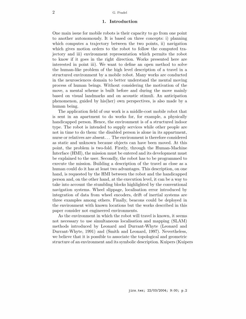
and Byan, 1991) defined symbols as distinct places situated at equaldistances from the nearby obstacles. Connections between these placeslink symbols and represent free path (Choset and Nagatani, 2001).Figure 1 shows the Voronoii graph of an environment. In this figure,the labelled vertices represent the symbols while edges connecting thesymbols are the path the robot can use.
2
3
1
5 69
874
Figure 1.: Voronoii diagram whith numbers label symbols
SensorSymbolic
Description
Builder
Pertinence
Evaluation
Symbolic
ComparatorDescriptionSymbolic
Saver
EnvironmentSymbolic descriptions
Voronoii verticescorresponding to
VoronoiiGraph
BuilderEnvironment
DescriptionSymbolic
Saver
SymbolicDescription
Builder
Moving processRobot
Navigator
Simulator
Mental moving process
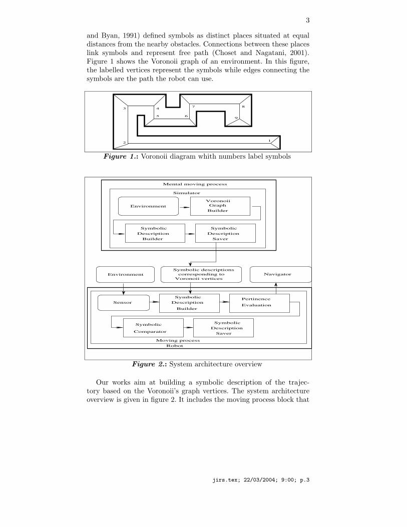
Figure 2.: System architecture overview
Our works aim at building a symbolic description of the trajec-tory based on the Voronoii’s graph vertices. The system architectureoverview is given in figure 2. It includes the moving process block that
jirs.tex; 22/03/2004; 9:00; p.3

4 G. Pradel
simulates the mental process by which a human being foresees a movein an environment. Assuming that the real environment is known, theVoronoii diagram is built by the Voronoii Graph Builder and for allthe vertices situated on the robot’s route, a symbolic description of theenvironment is made by the Symbolic Description Builder and saved.The set of these descriptions constitutes a high level description of therobot’s route that will be used by the robot to symbolically localise inthe environment. When the real robot is launched in the environmenton a trajectory, a symbolic description is built from the sensor raw dataevery time a measurement is made. Their pertinence is evaluated andcompared with the mental process output to drive the navigator.
Thus, the problem is building the symbolic description of the routefollowed by the robot. In fact, the question is three-fold: how to buildthe qualitative descriptions in accordance with the robot’s sensors, howto describe the route by a sequence of the most pertinent descriptionsand how to use these descriptions with the control-command levelof the robot. The symbolic builder architecture is fully developpedin (Pradel and al., 2000). This paper is focussed on the evaluationof what new information is brought up by a new symbolic descrip-tion. Since the approach is mainly qualitative, we do not need precisescalar quantities to denote the position of a landmark insofar the robotdoes not hit it. We choose to describe the surrounding environmentby means of landmarks such as ”Opening, Closure, End of Closure,Angle of Closures,...” organised into ordered series called frescoes ac-cording to the data delivered by the sensors. These landmarks arethe most perceivable (consistent) and the most easily distinguishable(distinctive) whatever the sensor used. One immediately thinks to thememorisation of the frescoes describing the parts of the environmentsthat the robot chronologically covers during a journey leading to thesymbolic description of the trajectory.
2. Related works
Related works can be found in the fields of Image Based Navigationsystems, shape understanding using sensor data, vision based homing.Vision for mobile robot navigation did have specific development duringthe last twenty years. (DeSouza and Kak, 2002) gives a complete surveyof the different approaches. For indoor navigation, systems are classi-fied in three groups: map-based navigation using predefined geometricand/or topological models, map-building-based navigation construct-ing by themeselves geometric and/or topological models, and mapless
jirs.tex; 22/03/2004; 9:00; p.4
5
navigation using only object recognition and actions associated to theseobjects (Gaussier and al., 1997).
In Image Based Navigation systems, several great classes of sys-tems can be identified from the literature. The first one uses con-ventional telemeters and vision to find and identify objects in theenvironment (Wichert, 1996). The second one is the class of the systemscoupling more or less directly sensor data to motor control thanks toa supervised learning process. Among them neural networks systemsused as classifiers are noticeable. These systems begin to classify theenvironment into global classes such as ”corridor, corner, room, crossing...” (Al Allan, 1996) (Pomerleau, 1993) are often followed by a secondprocessing unit that outputs a navigation command. In addition torestrictions related to the supervised learning, these classes give only aglobal description and are of least interest in cluttered and complexenvironments. The third class includes the systems which comparecurrent sensor data and predefined models both at a low level (edges,planes ...) (Kim and Neviata, 1994) and at a high level (door, room,object ...). These systems use mainly vision sensors (cameras) thatprovide a huge amount of data that must be reduced to be processedin real time. The elements extracted from the data are compared toreference models known a priori. The fourth class evoked here includesthe systems trying to geometrically build environment models beforedeciding an optimised path plan (Crosnier, 1999).
In the field of shape understanding using sensor data, environmentinterpretation stresses the use of natural landmarks to ease the naviga-tion and the pose estimation of a mobile robot. Among other works, onecan pinpoint (Simhon and Dudek, 1998) which is interested in definingislands of reliability for exploration. He proposes strategies to couplenavigation and sensing algorithms through hybrid topological metricmaps. (Oore and al., 1997) considers the problem of locating a robotin an initially unfamiliar environment from visual input. In the sameway, (MacKenzie and Dudek, 1994) involves a methodology to bindraw noisy sensor data to a map of object models and an abstract mapmade of discrete places of interest.
Several implementations of vision based homing systems are pre-sented in (Franz and al., 1997). A method aiming at highlighting salientfeatures, as for example landmarks, between these two views and deriv-ing a decision is used in (Hong, 1991). In these works, a homing systemextracts landmarks from the view and allows a robot to move to homelocation using sequence target locations situated en route between itscurrent location and home. Other works are biologically inspired. (Juddand Collett, 1998) showed that ants store series of snapshots at differentdistances from their goal to use them for navigating during subsequent
jirs.tex; 22/03/2004; 9:00; p.5

6 G. Pradel
journeys. Judd and Collett experimented their theory with a mobilerobot navigating through a corridor, homing successive target loca-tions. (Weber and al, 1999) proposes an approach using the bearingsof the features extracted of the panoramic view leading to a robusthoming algorithm. This algorithm pairs two landmarks situated intotwo snapshots to derive the homing direction. The bearings pairingprocess uses a list of preferences similar to neighbourhood rules.
Symbolic processing methods are described in Tedder’s works (Ted-der and Hall, 2001). This formal approach is often called structuralor syntactic description and recognition. The general method for per-ception and interpretation proposes to symbolically represent and ma-nipulate data in a mapping process. (Tedder and Hall, 2001) solve theproblem in modelling the 3D environment as symbolic data and inprocessing all data input on this symbolic level. The results of obstacledetection and avoidance experiments demonstrate that the robot cansuccessfully navigate the obstacle course using symbolic processing con-trol. These works use a laser range finder. A way for defining suitablelandmarks from an enviuronment as the robot travels is a researchproblem pointed out by Fleisher and al. in (Fleisher and al., 2003).An automatic landmark selection algorithm chooses as landmarks anyplaces where a trained sensory anticipation model makes poor predic-tions. The landmark detection system consists of a sensory anticipationnetwork and a method of detecting when the difference between theprediction of the next sensor values and the current measured valuescan reveal the presence of a landmark. This model has been appliedto the navigation of a mobile robot. An evaluation has been madeaccording to how well landmarks align between different runs on thesame route. These works show that the robot is able to navigate reliablyusing only odometric and landmark category information.
In (Lamon and al., 2001), a method is proposed for creating uniqueidentifiers called fingerprint sequences for visually distinct significantfeatures in panoramic images. This localisation system proves that theactual position of a robot in an environment can be recovered by con-structing a fingerprint sequence and comparing it wit a database ofknown fingerprints.
The proposed work goes on the way proposed by (Tedder and Hall,2001) and (Lamon and al., 2001). According to these works, our contri-bution applies mainly on a method to extract clues of interest amongraw distance data delivered by a 2D panoramic laser range finder in-stalled on the robot. These clues of interest, i.e. the landmarks, aregathered in a sequence that we call a fresco. We consider that thetrajectory of the robot can be described by the set of the frescoes. Todo that, we have to select the frescoes that bring new information. The
jirs.tex; 22/03/2004; 9:00; p.6

7
originality of this work stays in the simple but efficient criteria used forthe construction and the validation of the fresco baut mainly to selectthe most pertinent frescoes along the route of the robot. In addition tothis qualitative approach, one must consider that the system will haveto be embarked on a vehicle, which vibrates, runs at variable speeds on anon-uniform ground. This leads to constraints of speed, size, robustness,compactness and cost, implying various choices both at the design andat the development levels of the system. The methods used have beenchosen as simple as possible to reduce the cost and the complexityof the processing. Nevertheless the method must be robust comparedwith the robot movements, the sensor accuracy and the variations ofthe complexity of the environment.
The paper firstly presents the landmarks used (section 3 and thecriteria used to select the relevant frescoes (sections 3.1 and 3.2). Sec-tion 4 briefly explains the fresco construction (section 4.1). Section 4.2shows and discusses the experimental results in simple environmentand section 4.3 examplifies the behaviour of the system in a complexenvironment. We conclude with ways to improve the method.
3. Criteria used to detect relevant changes in theenvironment evaluation
As told in the introduction, environments are described using a frescomade of ordered series of landmarks. An example of fresco is given infigure 4f. The robot is situated in the middle of the environment. Theenvironment is divided in four quadrants. In each quadrant appears avariable number of landmarks. The set of landmarks is shown in table 3.
To each landmark are associated three qualitative attributes rep-resenting three properties of landmarks. The off-sight attribute is setwhen the landmark stands close to or beyond the end of the sensorrange. The position attribute can take the following values: crosswise,diagonal or lengthwise according its position related to the lenghtwiseand crosswise robot axis. The certainty attribute is introduced to takeinto account landmarks whose evolution can be forecast. It is false forevery landmark (for instance, diagonal ”End of Closure”, ”45o angles”)that could come from a possible noise introduced in the digitisationprocess and whose evolution cannot be known.
Every time the laser range finder scans the environment, a frescois built. In our case, the fresco built-in period is 300ms. Hence, if allfrescoes are stored, one, their number grows quickly and, second, someof them are not useful. Storing all the frescoes when the robot runs ina corridor is a trivial example. All frescoes are very similar excepted
jirs.tex; 22/03/2004; 9:00; p.7

8 G. Pradel
Table I. Landmark language used in the fresco construction
Symbol Landmark Position Off-sight Certainty
Angle of Closure true
End of Closure lengthwise true
End of Closure lengthwise off sight false
End of Closure crosswise true
End of Closure crosswise off sight false
End of Closure diagonal1 false
End of Closure diagonal1 off sight false
End of Closure diagonal2 false
End of Closure diagonal2 off sight false
45oAngle lengthwise false
45oAngle crosswise false
Opening lengthwise true
Breakthrough lengthwise true
15 Opening crosswise true
Breakthrough crosswise true
at both ends. If only few frescoes are useful, how then is it possible toselect them? Is a specific sequence of frescoes able to describe a partof the environment? Answering, at least partially, to these questions isthe aim of this paper. Two criteria, called barycentre and resemblance,are proposed to evaluate a kind of distance between frescoes. A newfresco is kept only if its distance to the previous stored one regardingone of the criteria is greater than a threshold. The two next sections
jirs.tex; 22/03/2004; 9:00; p.8

9
describe these criteria. A systematic study gives an evaluation of thethresholds to use to make the criteria effective.
3.1. Resemblance evaluation between two frescoes
This criterion uses a nearby principle of that presented in (Hong, 1991).A correlation function allows to calculate the resemblance between twofrescoes. This criterion has been tested in the same environment asthat used for the construction and the validation of the frescoes. Theuse of this criterion shows that the landmarks that are not certainmake very difficult the evaluation of the resemblance so only the certainelements were kept. The resemblance between two consecutive frescoesis calculated by taking into account the difference between the numberof certain landmarks in the respective quadrants of two consecutivefrescoes. The comparison of this difference with a reference thresh-old indicates if the current fresco should be kept or rejected becausenot bringing enough information. The algorithm used to compute theresemblance is (Algorithm 1):
Function Resemblance( Fi,Fj : fresco) : pertinent : boolean
Compute Ni[0], Ni[1], Ni[2], Ni[3]
the number of certain landmarks in quadrants
0, 1, 2, 3 respectively in fresco Fi;
Compute Nj [0], Nj [1],Nj [2],Nj [3]
the number of certain landmarks in quadrants
0, 1, 2, 3 respectively in fresco Fj ;
Compute the resemblance between frescoes Fi and Fj :
rij = |N0i −N0j |+ |N1i −N1j |+|N2i −N2j |+ |N3i −N3j |;
End
Algorithm 1: Resemblance algorithm
3.2. Barycentre evaluation between two frescoes
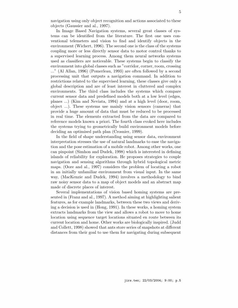
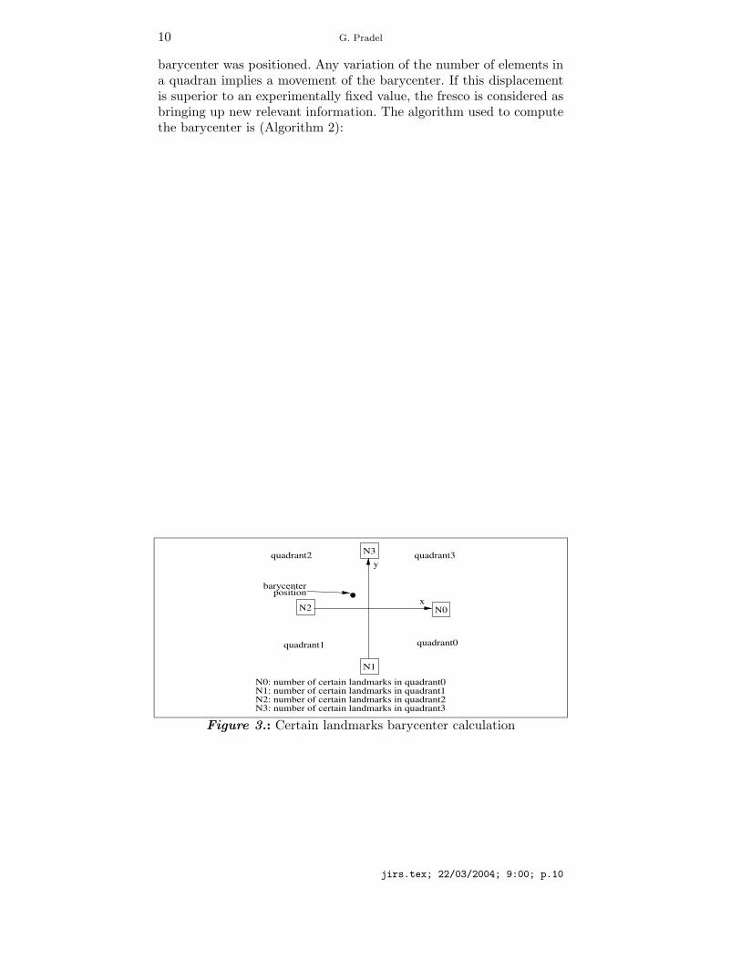
This criterion is inspired by the distance of Hausdorff which measuresthe distance between two sets (Ahuactzin and al., 1995) and (Hut-tenlocher, Klanderman and al., 1993). In our case, this notion wasvery simplified to respect real-time constraints. It takes into accountonly the number of certain landmarks in every quadrant. This num-ber of landmarks was positioned as indicated on the figure 3 and the
jirs.tex; 22/03/2004; 9:00; p.9
10 G. Pradel
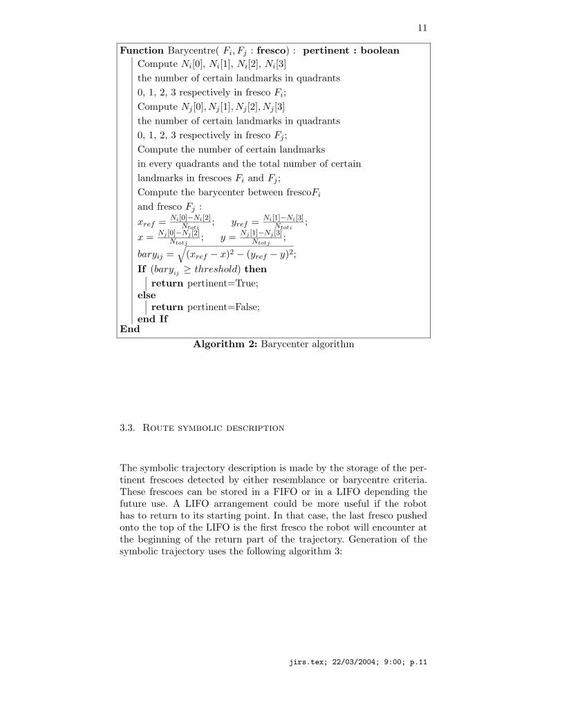
barycenter was positioned. Any variation of the number of elements ina quadran implies a movement of the barycenter. If this displacementis superior to an experimentally fixed value, the fresco is considered asbringing up new relevant information. The algorithm used to computethe barycenter is (Algorithm 2):
N1
N2
N3
N0
N1: number of certain landmarks in quadrant1N2: number of certain landmarks in quadrant2N3: number of certain landmarks in quadrant3
N0: number of certain landmarks in quadrant0
quadrant0quadrant1
quadrant2
positionbarycenter
quadrant3
x
y
Figure 3.: Certain landmarks barycenter calculation
jirs.tex; 22/03/2004; 9:00; p.10
11
Function Barycentre( Fi, Fj : fresco) : pertinent : boolean
Compute Ni[0], Ni[1], Ni[2], Ni[3]
the number of certain landmarks in quadrants
0, 1, 2, 3 respectively in fresco Fi;
Compute Nj [0], Nj [1], Nj [2], Nj [3]
the number of certain landmarks in quadrants
0, 1, 2, 3 respectively in fresco Fj ;
Compute the number of certain landmarks
in every quadrants and the total number of certain
landmarks in frescoes Fi and Fj ;
Compute the barycenter between frescoFi
and fresco Fj :
xref = Ni[0]−Ni[2]Ntoti
; yref = Ni[1]−Ni[3]Ntoti
;
x =Nj [0]−Nj [2]
Ntotj; y =
Nj [1]−Nj [3]Ntotj
;
baryij =√
(xref − x)2 − (yref − y)2;
If (baryij ≥ threshold) then
return pertinent=True;else
return pertinent=False;end If
End
Algorithm 2: Barycenter algorithm
3.3. Route symbolic description
The symbolic trajectory description is made by the storage of the per-tinent frescoes detected by either resemblance or barycentre criteria.These frescoes can be stored in a FIFO or in a LIFO depending thefuture use. A LIFO arrangement could be more useful if the robothas to return to its starting point. In that case, the last fresco pushedonto the top of the LIFO is the first fresco the robot will encounter atthe beginning of the return part of the trajectory. Generation of thesymbolic trajectory uses the following algorithm 3:
jirs.tex; 22/03/2004; 9:00; p.11

12 G. Pradel
Function SymbolicTrajectory() :
Fi, Fj : fresco
i : integer
Create a fresco from sensory data
Fi=Create fresco(sensory data);
Store the 1st fresco in the LIFO
Push Fresco(Fi);
While (!End trajectory) do
The robot moves and another fresco can be built
Create a fresco from sensory data
doneFj=Create fresco(sensory data);
If (criteria(Fi,Fj) == True) then
Push Fresco(FJ );end IfFi=Fj ;
End
Algorithm 3: Symbolic trajectory algorithm
4. Experimental results
4.1. Symbolic description
To build the fresco, the ”Opening, Closure, End of Closure, Angle of Closures”landmarks have to be extracted from the raw distance data givenby the panoramic laser range finder. Three steps are necessary. Thefirst one consists of environment perception. It is realised with a laserrange finder. The second step builds the digital representation of theenvironment. The third one extracts the landmarks. More details canbe found in (Pradel and al., 2000). The size of the non holonomousrobot is (width x length) 0.50m x 0.75m. Its linear and angular speedsare up to 1m/s and 2.45rad/s. The robot is placed at the geometricalcentre of the environment captured bt the panoramic telemeter. Sizesof the environment are 6m x 6m. Experiments in the following havebeen made with measurements coming from both a simulated laserrange finder and the real telemeter. Figure 4 examplifies the symbolicdescription process. Figure 4a shows the environment detected by the
jirs.tex; 22/03/2004; 9:00; p.12

13
sensor. When the laser beam hits an obstacle the corresponding cellwill appear in black in the cellular space. Elimination of the noise intro-duced by the oblique walls needs a reorientation and a filtering process(figures 4b and 4c) (Bras and al., 1995). Extraction of the landmarks(”End of Closure”, ”Closure” and ”Angle of Closures”) from the grid ismade by a set of laws similar to those used in cellular automata (Pradeland al., 2000). Figures 4d and 4e examplify the landmark extractionprocess for the ”Angle of Closures” and ”End of Closure” landmarks.Finally, figure 4f shows the corresponding fresco.
a(upper left): real world from raw measurements,b(upper centre): reoriented cellular space,c(upper right): refined space after superfluous data elimination,d(lower left): Angles of Closure extraction,e(lower centre): End of Closure extraction,f(lower right): Constructed fresco.
Figure 4.: Example of the digitised constructions:
Building the fresco uses the language presented in table 3 whichgathers landmarks identity and attributes. This operation aims mainlyat eliminating the notion of distance to the profit of a spatial seriesand highlights the qualitative representation of the environment. Everytime a fresco is built, a validation checking is made thanks to strict lawsof neighbourhood (for example, the neighbours of an Angle of Closurecan only be Angle of Closures or End of Closures) and either the frescois saved or lost with only slight effects on the mission of the robot.
jirs.tex; 22/03/2004; 9:00; p.13

14 G. Pradel
Moreover, the disturbance introduced by this loss is very attenuatedbecause the process of transitions detection and environment memori-sation eliminates a great part of the frescoes. When it is validated, thefresco appears as shown in figure 4f. A fresco will contain at most 64landmarks symbols. At this point, a certainty attribute is introduced toreflect the evolution of the landmarks when the robot is moving. Thisevolution is well defined for the certain landmarks while it is not forthe other ones (e.g.: an End of closure off-sight can transform in itselfor End of closure or Angle).
4.2. Application of the criteria in simple environment
The two criteria apply only on the certain landmarks and have beentested in two types of environments. In a first step, experiments insimple environments led us to point out the thresholds relevant ranges.In a second step, a complex environment has been used to validatethese thresholds.
The problem is to find the right threshold for each criterion. Arepresentative panel of situations is first established and systematictests are made on each situation in which the frescoes are listed fordifferent thresholds of the two criteria. Then a reference threshold foreach criterion is fixed taking into account firstly the ratio of kept fres-coes and secondly the position of these frescoes with respect to theirsituation along the robot’s route in the considered environment. Finally,thresholds that have been defined are tested in a complex environment.
4.2.1. Choice of different types of environmentIndoor environments can be described using a limited number of situa-tions (Al Allan, 1996): openings, walls, angles, room, corridor, dead-endand crossings. So far, tested situations are listed in table 4.2.1.
Figure 5 shows the example of the ”opening on the left situation”.Numbers on the left of the figure show the different positions wherefrescoes have been constructed. In this example, frescoes are built fromposition 1 to position 31 (only one of five is drawn to make the figurereadable).
jirs.tex; 22/03/2004; 9:00; p.14

15
Figure 5.: Example of situation: Opening on the left
In the different situations, the initial numbers of frescoes are different(Table 4.2.1).
Table II. Initial number of built frescoes
Situation Abbrev. Number of frescoes
Angle to the left AL 31
Angle to the right AR 31
Opening on the left OL 31
Opening on the right OR 31
X-crossing CX 42
4.2.2. Number of pertinent frescoes vs. criterionIt is firstly interesting to observe the number of frescoes kept for dif-ferent values of thresholds. For barycenter criterion, values between 0and 2 with a step of 0.05 are tested. For resemblance criterion, valuesbetween 0 and 12 with a step of 0.5 are tested. Beyond these limits, onlyfresco number one is kept. As the initial number of frescoes is differentin all situations, the ratio between the number of frescoes kept and
jirs.tex; 22/03/2004; 9:00; p.15
16 G. Pradel
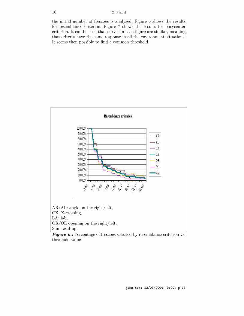
the initial number of frescoes is analysed. Figure 6 shows the resultsfor resemblance criterion. Figure 7 shows the results for barycentercriterion. It can be seen that curves in each figure are similar, meaningthat criteria have the same response in all the environment situations.It seems then possible to find a common threshold.
AR/AL: angle on the right/left,CX: X-crossing,LA: lab,OR/OL opening on the right/left,Sum: add up.
Figure 6.: Percentage of frescoes selected by resemblance criterion vs.threshold value
jirs.tex; 22/03/2004; 9:00; p.16

17
AR/AL: angle on the right/left,CX: X-crossing,LA: lab,OR/OL opening on the right/left,Sum: add up.
Figure 7.: Percentage of frescoes selected by barycenter criterion vs.threshold value
It also can be noted that curves fall quickly for low thresholds val-ues. In figure 5, frescoes between 1 and 10 represent the same partof the environment with very slight differences. The objective is tokeep a reasonable part of frescoes between 10% and 20% in the firstapproximation. For resemblance criterion, that means thresholds valuesbetween 5 and 7 and between 0.4 to 0.6 for barycenter criterion.
4.2.3. Positions of pertinent frescoesFor both criteria, it is interesting to visualise which frescoes are con-sidered as pertinent. For the barycenter criterion applied to the ”angleon the left” situation, figures 8, 9, 10, 11 and 12 show the positions ofthe pertinent frescoes vs. the threshold value.
jirs.tex; 22/03/2004; 9:00; p.17

18 G. Pradel
Figure 8.: Pertinent frescoes vs barycenter criterion; threshold=0.40
Figure 9.: Pertinent frescoes vs barycenter criterion; threshold=0.45.
jirs.tex; 22/03/2004; 9:00; p.18

19
Figure 10.: Pertinent frescoes vs barycenter criterion; threshold=0.50(AL situation).
Figure 11.: Pertinent frescoes vs barycenter criterion; threshold=0.55(AL situation).
jirs.tex; 22/03/2004; 9:00; p.19

20 G. Pradel
Figure 12.: Pertinent frescoes vs barycenter criterion; threshold=0.60(AL situation).
Frescos number 1 and 31 represent the beginning and the end of thetrajectory: they appear for all the thresholds. Frescoes 9, 11, 13 and24 represent the heart of the turning. They are very close consideringEuclidean distance but they differ in term of orientation. Fresco number24 disappears for thresholds equal to 0.55 or 0.60. The value 0.50 isthe central threshold value for barycenter criterion. A similar analy-sis has been conducted for all other situations. In the same way, theresemblance criterion leads to the same conclusion with 6.0 as centralthreshold.
4.2.4. DiscussionIf only the number of the frescoes considered as pertinent to describethe travel of the robot is taken into account, we firstly see that theresponse for each criterion is similar for every situations and, secondly,that for every criterion the thresholds values giving the best resultsare very close. It is then possible to evaluate an acceptable thresholdwhatever the situation. This number is not significant of the efficiencyof the criteria. The position of selected frescoes plays an important role.The pertinent frescoes must be positionned as close as possible of thelabels of the Voronoii vertices. The visualisation of the selected frescoesfor all the combinations of situations and criteria shows that retainedfrescoes are well situated in the environment to have a satisfying rep-resentation. Figures 13 and 14 show the positions of pertinent frescoesvs. the criterion used. Resemblance criterion keeps 3 frescoes situatedbefore the opening, in the middle of the opening and after the opening.It is the best representation of the changes in the environment in terms
jirs.tex; 22/03/2004; 9:00; p.20

21
of concision and precision. In other situations, the barycenter criteriongives the best result.
Figure 13.: Position of pertinent frescoes with barycenter criteria (ALsituation).
Figure 14.: Position of kept frescoes with resemblance criteria (ALsituation).
jirs.tex; 22/03/2004; 9:00; p.21

22 G. Pradel
4.3. Complex environments
Figure 15.: Comparison of percentage of frescoes selected by resem-blance criterion in complex (LA) and simple environments vs threshold.
Figure 16.: Comparison of percentage of frescoes selected by barycen-ter criterion in complex (LA) and simple environments vs threshold.
A complete trajectory has been studied in a complex environment(figure 17). The two criteria have been applied. The variations of thethresholds have been limited to the range determined by the testsin simple environments: 5 to 7 for resemblance and 0.4 to 0.6 forbarycenter. Figures 15 and 16 show the percentage of kept frescoes for
jirs.tex; 22/03/2004; 9:00; p.22

23
desks
Robot
cupboards
5
10
1525
20
30
35
Robot’s position on its route
Figure 17.: Test environment: the lab
both criteria. For barycenter criterion, there is no significant differencebetween the complex and the simple environments. For resemblancecriterion, the ratio is greater in the complex environment than in thesimple ones. Nevertheless, for a threshold equal to 7.0, the ratio be-comes close to the ratio obtained in simple environments. Figure 18shows pertinent frescoes for the resemblance criterion with a thresholdequal to 7.0. Figure 19 shows pertinent frescoes for the barycentercriterion with a threshold equal to 0.4.
jirs.tex; 22/03/2004; 9:00; p.23

24 G. Pradel
Figure 18.: Position of pertinent frescoes with resemblance criterionin the complex environment.
Figure 19.: Position of pertinent frescoes with barycenter criterion inthe complex environment.
jirs.tex; 22/03/2004; 9:00; p.24

25
5. Conclusion and perpectives
Human beings, as well as insects (Collett and al., 1992), use resem-blance (or dissimilarity) to compare views of the environment rejectingthose that do not bring up new elements without using metrics, only us-ing the occurence of landmarks. In this paper, we present a qualitativemethod inspired of homing methods (Weber and al, 1999) to con-struct the environment surrounding an indoor mobile robot equippedwith a 2D telemetry sensor. Every times distance measurements aremade, landmarks are extracted and organised into series called frescoes.From this point, distance information are not more used. In order toderive the pertinent frescoes that can describe the trajectory of therobot, we plan to use a pairing-like method. The first criterion thatis primarily being investigated uses a resemblance between two fres-coes. The landmarks are bounded and a correlation function measuresthe difference between consecutives frescoes. The second criterion isbased on the difference between the barycentre positions of consecu-tive frescoes(Huttenlocher, Klanderman and al., 1993). Those frescoesseparated by a difference higher than a threshold are considered aspertinent to describe the robot’s route. In both cases the differencesare compared with thresholds that are experimentally set up. Despitethe criteria simplicity, the results in the very changing test environment(figure 17) show that the thresholds experimentally trimmed in simpleenvironments are well fitted to a complex environment.
Depending the environment, it has to be noticed that the behaviourof the two criteria can differ and one can be a bit more efficient than theother. An improvement of the method will introduce a global informa-tion situation in the choice of the best criterion. A neural classifier willoutput the class of the situation of environment. According this class,the most efficient criteria, resemblance or barycentre, will be chosen.Another direction should be the use of more sophisticated criteria suchas, for example, Lievenshtein distance. A good evaluation of the criteriacould be their use in a return journey. Remember that the applicationfield of the robot is supplying services for a handicapped person. Therobot has to go in the flat and move back to the user. If it is able to goback to its starting point, we do consider that the method is validated.
References
J. Ahuactzin and E. Mazer and P. Bessiere. L’algorithme fil d’Ariane, Revued’intelligence artificielle, 9(1):7-34, 1995.
jirs.tex; 22/03/2004; 9:00; p.25
26 G. Pradel
S. Al Allan. Reconnaissance d’environnement et navigation ractive d’un robot mo-bile autonome par rseaux de neurones, Universite d’Evry-Val d’Essonne, France,PhD, feb, 1996.
F. Bras and G. Pradel and Z. Jin. Cellular Automata Applied to the Path Generationand Environment Representation for a Mobile Robot, IFAC Motion ControlConference, Munich, Germany, 395-402, oct, 1995.
T. Collett and E. Dillmann and A. Giger and R. Wehner. Visual landmarks androute following in desert ants, Journal of Comparative Physiology A SpringlerVerlag, 170:435-442, 1992.
A. Crosnier. Modelisation geometrique des environnements en robotique mobile,French Workshop on Robotic Resarch (Journees Nationales de la Recherche enRobotique), Montpellier, France, 83-91, sep, 1999.
M. Franz and B. Scholkopf and H. Bulthoff. Image-based Homing, Proceedings ofthe European Conference on Artificial Life, 236-245, 1997.
P. Gaussier and C. Joulain and S. Zrehen and A. Revel. Image-based Homing,Proceedings of the IEEE International Conference on Intelligent Robots systems,545-550, sep, 1997.
G. N. DeSouza and A. C. Kak. Vision for mobile robot navigation: a survey, IEEETransaction on pattern analysis and machine intelligence, 24(2):237-267, feb,2002.
J. Hong. Image-based Homing, Proceedings of the IEEE International Conferenceon Robotics and Automation,Sacramento, USA, 620-625, apr, 1991.
D. Huttenlocher and G. Klanderman and W. Rucklidge. Comparing images us-ing Hausdorff distance, IEEE Transactions on pattern analysis and machineintelligence, 15(9):850-863, 1993.
S. Judd and T. Collett. A Mobile Robot That Learns Its Place, Nature, 392:710-714,apr, 1998.
D. Kim and R. Neviata. A method for recognition and localization of generic objectsfor indoor navigation, Proceedings of ARPA Image Understanding Workshop,Monterey, USA, 13-16, nov, 1994.
P. MacKenzie and G. Dudek. Precise Positioning using Model-Based Maps, Proceed-ings of IEEE International Conference on Robotics and Automation, San Diego,USA, 1615-1621, may, 1994.
S. Oore and G. Hinton and G. Dudek. A Mobile Robot That Learns Its Place,Neural Computation, MIT Press, 9(3):683-699, 1997.
D. A. Pomerleau. Neural Network Perception for Mobile Robot Guidance, KluwerAcademic Publishers, 1993.
G. Pradel and F. Bras and Z. Jin. 2D laser telemetry-based path trend generationand real time environment symbolic representation for an autonomous mobilerobot, Proceedings of the IFAC-IEEE International Conference on MachineAutomation,Tampere, Finland, 122-134, feb, 1994.
G. Pradel and S. Avrillon and L. Garbuio. Landmark interpretation by means offrescoes in mobile robotics, Proceedings of the 6th Int. Conf. On Methods andModels in Automation and Robotics, Miedzyzdroye, Poland, 585-592, aug, 2000.
G. Pradel and F. Bras. Qualitative environment description by means of frescoes inmobile robotics, Journal europeen des systemes automatises, 9(35):1105-1128,2001.
S. Simhon and G. Dudek. A global Topological Map formed by Local MetricMaps, Proceedings of IEEE/RSJ International Conference on Intelligent RoboticSystems, Victoria, B.C., Canada, 1708–1714, oct, 1998.
jirs.tex; 22/03/2004; 9:00; p.26

27
S. Simhon. Islands of Reliability for Dual Topological-Metric Mapping, Depart-ment of Computer Science,Sep 1998, Centre for Intelligent Machines, McGillUniversity, Montreal, Canada, PhD, sep, 1998.
K. Weber and S. Venkatesh and M. V. Srinivasan. Insect Inspired Robotic Homing,Adaptive Behavior, 1:65-98, 1999.
G. Wichert. Selforganizing Visual Perception for MobileRobot Navigation, available at url = www.rt.e-technik.th-darmstadt.degeorg/pubs/EUROBOTS96/paper.html”, 1996.
M. Tedder and L. E. Hall. Symbolic processing methods for 3D visual preocessing,available at url = www.robotics.uc.edu/papers2001/Maurice2001d.pdf, 2001.
J. Fleisher and S. Marshland and J. Shapiro. Sensory anticipationfor autonomous selection of robot landmarks, available at url =http://www.cs.man.ac.ukfleischj/research.html, Foundations, Theories, andSystems, Lecture Notes in Artificial Intelligence, 2664, 2003.
J. J. Leonard and H. F. Durrant-Whyte. Simultaneous map building and localizationfor an autonomous mobile robot, Proceedings of the IEEE/RSJ Int. Workshop onIntelligent Robots and Systems IROS’91, New York, NY, USA,1442-1447, may1991.
C. M. Smith and J. J. Leonard. Proceedings of International Conference on Field andService Robotics, Canberra, Australia, 249-256dec, 1997. A multiple-hypothesisapproach to concurrent mapping and localization for autonomous underwatervehicles,
B. Kuipers and Y. T. Byan. A robot exploration and mapping strategy basedon a semantic hierarchy of spatial representation, Int. Journal of AutonomousSystems, 8:47-63, 1991.
H. Choset and K. Nagatani. Topological Simultaneous localization and Map-ping (SLAM): Toward Exact Localization without Explicit Localization, IEEETransaction on Robotics and Automation, 2(17):125-137, 2001.
P. Lamon and I. Nourbakhsh and B. Jensen and R. Siegwart. Deriving and Match-ing Image Fingerprint Sequences for Mobile Robot Localization, available aturl = citeseer.nj.nec.com/445679.html, Proceedings of the IEEE InternationalConference on Robotics and Automation, Seoul, Korea, may, 2001.
jirs.tex; 22/03/2004; 9:00; p.27

jirs.tex; 22/03/2004; 9:00; p.28