symcom model 777 / 777-lr / 777-575 overload relays · 777 manual remote reset kit the manual...
TRANSCRIPT
Recordable voltage, current, last 4 faults, KWh usage, and powerfactor is available whenusing communications package.
Digitally programmablefor precise customizing.
Sixteen set points can be programmed for maximum protection.
Last fault memory provides instant trouble-shooting diagnostics.
UL and cUL listed as anoverload relay.
RS485 communicationport for use with computerized systemsusing Modbus protocol.
Features
Applications
Description
The Model 777 can be used on any 3-phase motor drawing 2-800 amps. Applications includeCONVEYOR SYSTEMS, HVAC EQUIPMENT, PUMPS, SAWS, GRINDERS AND OTHER 3-PHASEELECTRIC MOTORS.
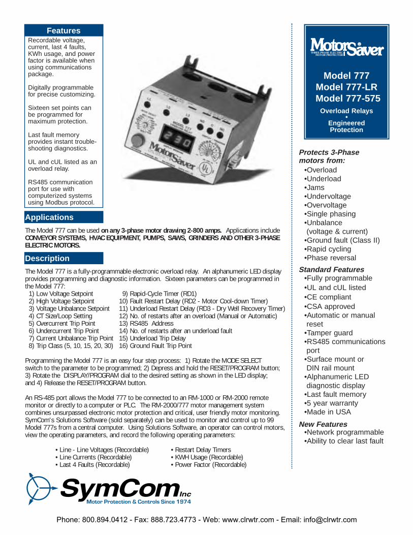
The Model 777 is a fully-programmable electronic overload relay. An alphanumeric LED displayprovides programming and diagnostic information. Sixteen parameters can be programmed inthe Model 777:
1) Low Voltage Setpoint 9) Rapid-Cycle Timer (RD1)2) High Voltage Setpoint 10) Fault Restart Delay (RD2 - Motor Cool-down Timer)3) Voltage Unbalance Setpoint 11) Underload Restart Delay (RD3 - Dry Well Recovery Timer)4) CT Size/Loop Setting 12) No. of restarts after an overload (Manual or Automatic)5) Overcurrent Trip Point 13) RS485 Address6) Undercurrent Trip Point 14) No. of restarts after an underload fault7) Current Unbalance Trip Point 15) Underload Trip Delay8) Trip Class (5, 10, 15, 20, 30) 16) Ground Fault Trip Point
Programming the Model 777 is an easy four step process: 1) Rotate the MODE SELECT switch to the parameter to be programmed; 2) Depress and hold the RESET/PROGRAM button; 3) Rotate the DISPLAY/PROGRAM dial to the desired setting as shown in the LED display; and 4) Release the RESET/PROGRAM button.
An RS-485 port allows the Model 777 to be connected to an RM-1000 or RM-2000 remote monitor or directly to a computer or PLC. The RM-2000/777 motor management system combines unsurpassed electronic motor protection and critical, user friendly motor monitoring.SymCom's Solutions Software (sold separately) can be used to monitor and control up to 99Model 777s from a central computer. Using Solutions Software, an operator can control motors,view the operating parameters, and record the following operating parameters:
• Line - Line Voltages (Recordable) • Restart Delay Timers• Line Currents (Recordable) • KWH Usage (Recordable)• Last 4 Faults (Recordable) • Power Factor (Recordable)
Model 777 Model 777-LRModel 777-575
Overload Relays •
EngineeredProtection
•Overload•Underload•Jams•Undervoltage•Overvoltage•Single phasing•Unbalance (voltage & current)
•Ground fault (Class II)•Rapid cycling•Phase reversal
•Fully programmable•UL and cUL listed•CE compliant•CSA approved•Automatic or manual reset
•Tamper guard•RS485 communications port
•Surface mount orDIN rail mount
•Alphanumeric LEDdiagnostic display
•Last fault memory•5 year warranty•Made in USA
•Network programmable•Ability to clear last fault
Protects 3-Phase motors from:
Standard Features
New Features
Phone: 800.894.0412 - Fax: 888.723.4773 - Web: www.clrwtr.com - Email: [email protected]
777 • 777-LR • 777-575Overload Relays
A B C
CONTACTOR
H1
X1
H1
X1
H1
X1
12 - 16 AWGStranded Wire
3 0MOTOR
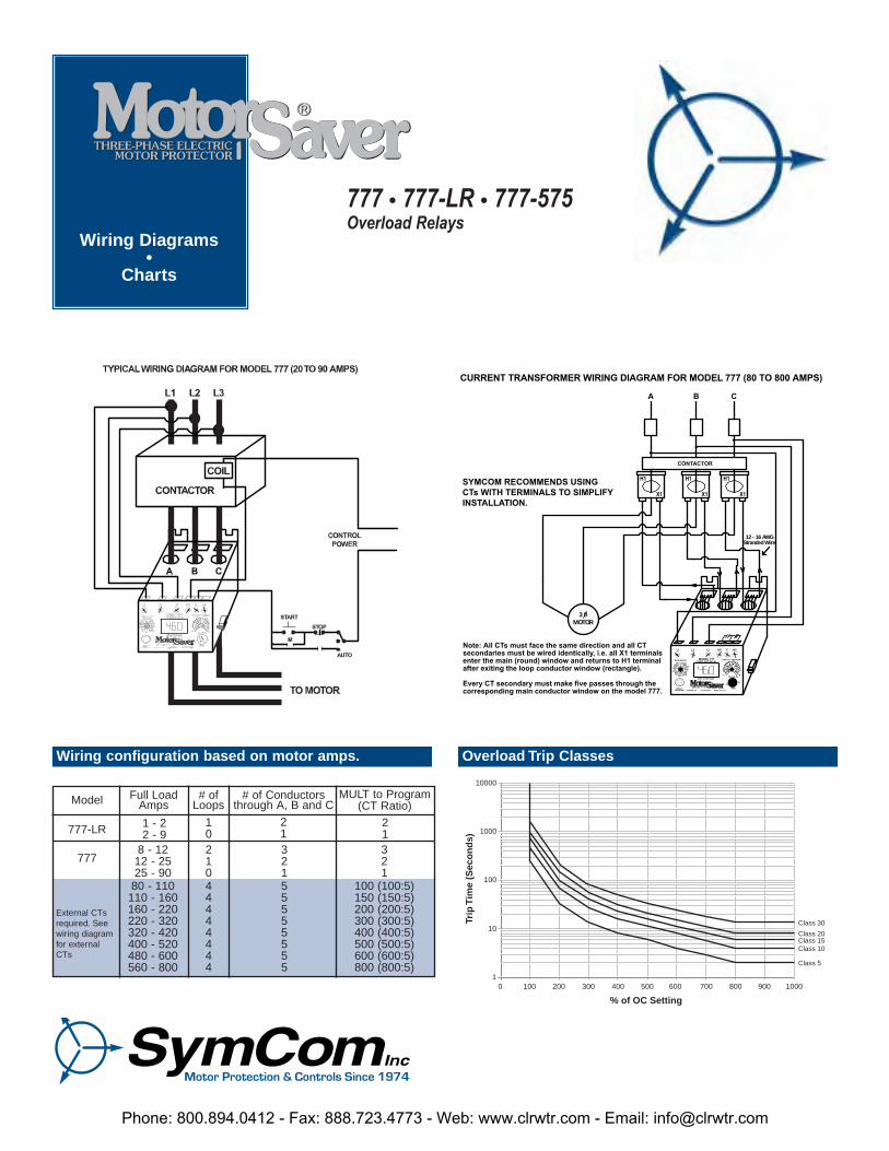
CURRENT TRANSFORMER WIRING DIAGRAM FOR MODEL 777 (80 TO 800 AMPS)
SYMCOM RECOMMENDS USING CTs WITH TERMINALS TO SIMPLIFYINSTALLATION.
Note: All CTs must face the same direction and all CTsecondaries must be wired identically, i.e. all X1 terminalsenter the main (round) window and returns to H1 terminalafter exiting the loop conductor window (rectangle).
Every CT secondary must make five passes through thecorresponding main conductor window on the model 777.
DISPLAY / PROGRAM
L3-L1L3-L1L B E
+
OV AVGAVG
T
L1-L2L1-L2
L2-L3L2-L3 C
N
T
CEAA
G AVGAVG
R
R
U
RD2 UCTD
CUB LV
MULTUCOC
HVVUB
RD1TC
GFRUN
#RU / ADDRRD3 #RF
MODE SELECT
L1 L2 L3 NO C NC
MODEL 777OVERLOAD RELAY
DISPLAY MESSAGE
RESET/PROGRAM 800-843-8848SYMCOM, INC. RAPID CITY, SD
Wiring configuration based on motor amps. Overload Trip Classes
777
External CTsrequired. Seewiring diagramfor externalCTs
777-LR
Model
1 - 22 - 9
Full LoadAmps
# ofLoops
10
# of Conductorsthrough A, B and C
21
MULT to Program(CT Ratio)
21
8 - 1212 - 2525 - 9080 - 110110 - 160160 - 220220 - 320320 - 420400 - 520480 - 600560 - 800
21044444444
32155555555
321
100 (100:5)150 (150:5)200 (200:5)300 (300:5)400 (400:5)500 (500:5)600 (600:5)800 (800:5)
10000
1000
100
10
0 300 400 500
% of OC Setting
Trip
Tim
e (S
eco
nd
s)
600 700 800 900 1000
Class 10
Class 30
Class 20Class 15
Class 5
2001001
Wiring Diagrams•
Charts
Phone: 800.894.0412 - Fax: 888.723.4773 - Web: www.clrwtr.com - Email: [email protected]
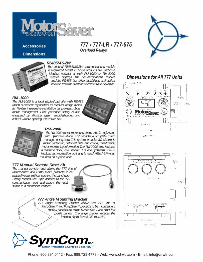
777 Manual Remote Reset KitThe manual remote reset allows the 777 line ofMotorSaver® and PumpSaver® products to be manually reset without opening the panel door.Simply connect the 9-pin adapter to the 777communication port and mount the resetswitch in a convenient location.
RM-1000The RM-1000 is a local display/controller with RS-485Modbus network capabilities. Its modular design allowsfor flexible, inexpensive installation yet provides robustmotor management. Plant personnel safety is alsoenhanced by allowing system troubleshooting and control without opening the starter box.
Dimensions for All 777 Units
777 • 777-LR • 777-575Overload Relays
4.5"
4.0"
3.3"
777 Angle Mounting Bracket777 Angle Mounting Bracket allows the 777 line of
MotorSaver® and PumpSaver® products to be mounted intoshallow panels such as the Furnas Size 1 and other low
profile panels. The angle bracket reduces theinstalled depth from 5.05" to 4.25".
RS485MS-2WThe optional RS485MS-2W communications moduleis required if Model 777-type products are used on aModbus network or with RM-1000 or RM-2000remote displays. The communications module provides RS-485 bus drive capabilities and opticalisolation from the overload electronics and powerline.
Accessories•
Dimensions
RM-2000The RM-2000 motor monitoring device used in conjunctionwith SymCom’s Model 777 provides a complete motor
management system. This system provides full electronicmotor protection, historical data and critical, user-friendly
motor-monitoring information.The RM-2000 also featuresa real-time clock, 2x20 backlit LCD, one upstream RS-485Modbus communication port and is rated NEMA-3R whenmounted on a panel door.
Phone: 800.894.0412 - Fax: 888.723.4773 - Web: www.clrwtr.com - Email: [email protected]
NOTES: SymCom's 777 & 777-LR can be preprogrammed prior to installation by applying 120 VAC between the L1 and L2 terminals.* 575 volt Model (MS 777-575)** If J prefix is displayed in trip class setting, jam protection is enabled.*** If "oc" is disabled in the #RF setting, the overcurrent will be included as a normal fault and the relay will automatically
restart after RD2 expires,otherwise, manual reset is required after an overcurrent fault.
SpecificationsModel 777, Model 777-LR & Model 777-575
7/04
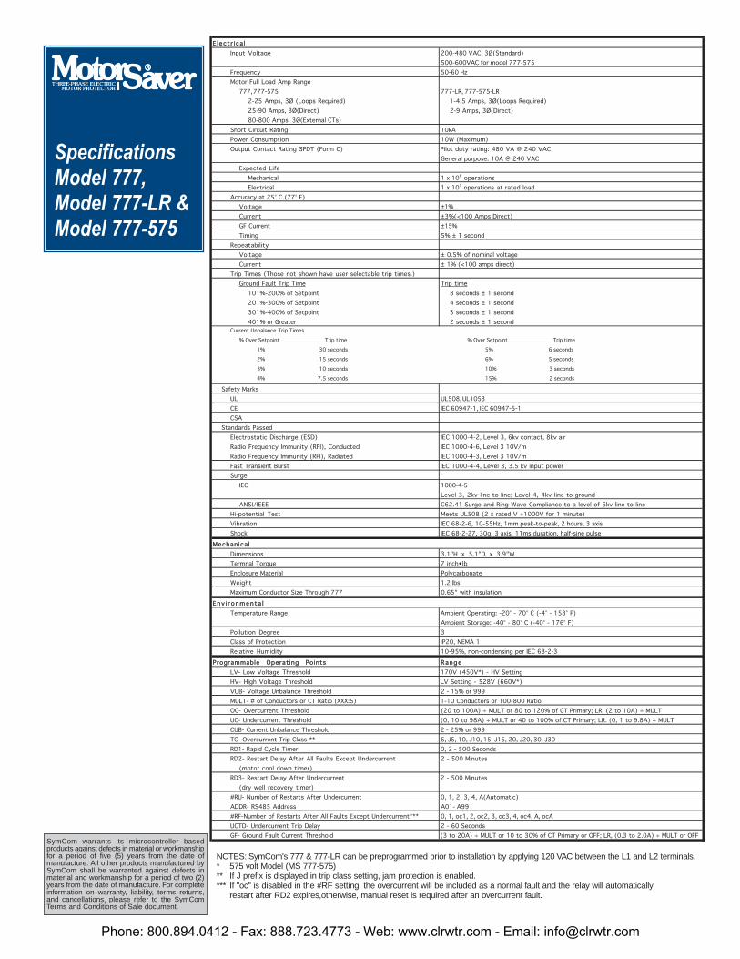
EE lleecctt rr ii ccaa llInput Voltage 200-480 VAC, 3Ø(Standard)
500-600VAC for model 777-575Frequency 50-60 HzMotor Full Load Amp Range
777, 777-575 777-LR, 777-575-LR2-25 Amps, 3Ø (Loops Required) 1-4.5 Amps, 3Ø(Loops Required)25-90 Amps, 3Ø(Direct) 2-9 Amps, 3Ø(Direct)80-800 Amps, 3Ø(External CTs)
Short Circuit Rating 10kAPower Consumption 10W (Maximum)Output Contact Rating SPDT (Form C) Pilot duty rating: 480 VA @ 240 VAC
General purpose: 10A @ 240 VACExpected Life
Mechanical 1 x 10⁶ operationsElectrical 1 x 10⁵ operations at rated load
Accuracy at 25° C (77° F)Voltage ±1%Current ±3%(<100 Amps Direct)GF Current ±15%Timing 5% ± 1 second
RepeatabilityVoltage ± 0.5% of nominal voltageCurrent ± 1% (<100 amps direct)
Trip Times (Those not shown have user selectable trip times.)Ground Fault Trip Time Trip time
101%-200% of Setpoint 8 seconds ± 1 second201%-300% of Setpoint 4 seconds ± 1 second301%-400% of Setpoint 3 seconds ± 1 second401% or Greater 2 seconds ± 1 second
Current Unbalance Trip Times
% Over Setpoint Trip time % Over Setpoint Trip time
1% 30 seconds 5% 6 seconds
2% 15 seconds 6% 5 seconds
3% 10 seconds 10% 3 seconds
4% 7.5 seconds 15% 2 seconds
Safety MarksUL UL508, UL1053CE IEC 60947-1, IEC 60947-5-1CSA
Standards PassedElectrostatic Discharge (ESD) IEC 1000-4-2, Level 3, 6kv contact, 8kv airRadio Frequency Immunity (RFI), Conducted IEC 1000-4-6, Level 3 10V/mRadio Frequency Immunity (RFI), Radiated IEC 1000-4-3, Level 3 10V/mFast Transient Burst IEC 1000-4-4, Level 3, 3.5 kv input powerSurge
IEC 1000-4-5Level 3, 2kv line-to-line; Level 4, 4kv line-to-ground
ANSI/IEEE C62.41 Surge and Ring Wave Compliance to a level of 6kv line-to-lineHi-potential Test Meets UL508 (2 x rated V +1000V for 1 minute)Vibration IEC 68-2-6, 10-55Hz, 1mm peak-to-peak, 2 hours, 3 axisShock IEC 68-2-27, 30g, 3 axis, 11ms duration, half-sine pulse
MMeecchhaanniiccaa llDimensions 3.1"H x 5.1"D x 3.9"WTermnal Torque 7 inch•lbEnclosure Material PolycarbonateWeight 1.2 lbsMaximum Conductor Size Through 777 0.65" with insulation
EEnnvv ii rr oonnmmeennttaa llTemperature Range Ambient Operating: -20° - 70° C (-4° - 158° F)
Ambient Storage: -40° - 80° C (-40° - 176° F)Pollution Degree 3Class of Protection IP20, NEMA 1Relative Humidity 10-95%, non-condensing per IEC 68-2-3
PPrrooggrraammmmaabbllee OOppeerraattiinngg PPooiinnttss RRaannggeeLV- Low Voltage Threshold 170V (450V*) - HV SettingHV- High Voltage Threshold LV Setting - 528V (660V*)VUB- Voltage Unbalance Threshold 2 - 15% or 999MULT- # of Conductors or CT Ratio (XXX:5) 1-10 Conductors or 100-800 RatioOC- Overcurrent Threshold (20 to 100A) ÷ MULT or 80 to 120% of CT Primary; LR, (2 to 10A) ÷ MULTUC- Undercurrent Threshold (0, 10 to 98A) ÷ MULT or 40 to 100% of CT Primary; LR. (0, 1 to 9.8A) ÷ MULTCUB- Current Unbalance Threshold 2 - 25% or 999TC- Overcurrent Trip Class ** 5, J5, 10, J10, 15, J15, 20, J20, 30, J30RD1- Rapid Cycle Timer 0, 2 - 500 SecondsRD2- Restart Delay After All Faults Except Undercurrent 2 - 500 Minutes
(motor cool down timer)RD3- Restart Delay After Undercurrent 2 - 500 Minutes
(dry well recovery timer)#RU- Number of Restarts After Undercurrent 0, 1, 2, 3, 4, A(Automatic)ADDR- RS485 Address A01- A99#RF-Number of Restarts After All Faults Except Undercurrent*** 0, 1, oc1, 2, oc2, 3, oc3, 4, oc4, A, ocAUCTD- Undercurrent Trip Delay 2 - 60 SecondsGF- Ground Fault Current Threshold (3 to 20A) ÷ MULT or 10 to 30% of CT Primary or OFF; LR, (0.3 to 2.0A) ÷ MULT or OFF
SymCom warrants its microcontroller based products against defects in material or workmanshipfor a period of five (5) years from the date of manufacture. All other products manufactured bySymCom shall be warranted against defects in material and workmanship for a period of two (2)years from the date of manufacture. For completeinformation on warranty, liability, terms returns,and cancellations, please refer to the SymComTerms and Conditions of Sale document.
Phone: 800.894.0412 - Fax: 888.723.4773 - Web: www.clrwtr.com - Email: [email protected]