sympress - gc america | together towards the best dental ... · sympress. nr. 6000-0000 / -1000 /...
TRANSCRIPT

Renfert GmbH • Industriegebiet • 78247 Hilzingen / GermanyTel. +49 7731 8208-0 • Fax +49 7731 [email protected] • www.renfert.comMade in Germany 21
-652
0 D
040
8
Rev
. 05
SYMPRESSNr. 6000-0000 / -1000 / -2000
Bedienungsanleitung Instruction manual • Mode d´emploi
Istruzioni d’uso • Instrucciones para el servicio
Seriennummer, Herstelldatum und Geräte-Version befinden sich auf dem Geräte-Typenschild.Serial number, date of manufacturing and unit version are shown on the type plate of the unit.Le numéro de série, la date de fabrication et la version se trouvent sur la plaque signalétique de l’appareil.Il numero di serie, la data di costruzione e la versione si trovano sulla targhetta dell’apparecchio.El número de serie, la fecha de fabricación y la versión del aparato están indicados en la placa identificadora del aparato.
1 32
4 5 6
7 8 9
10 11 12
14 15
16 17
13
18
19
- 9 - EN
IntroductionThe SYMPRESS unit for mixing impression materials facilitates extrusion and mixing of 2-component den-tal impression materials.5:1 cartridges or foil bags in cartridge holders from different manufacturers can be used in the unit.The mixer spindle allows the use of dynamic mixing tips with a hexagonal connection.A material sensor automatically retracts the plunger to the start position so that the cartridges can be exchanged quickly.
using these operating instructions as a starting point, instruct all operators of the unit with regard to the area of application, the possible hazards during operation, and the proper operation of the unit.
Observe the information on risks and ha-zards in section B.
Please have these operating instructions readily avai-lable for the operators.Additional information can be found in the Section, “Information for Operators”, at the end of these in-structions.
symbologyThe following symbols are employed in these instructions and on the unit itself:
On the unit: Adhere to the operating instructions!
In these instructions: caution serious risk of injury!
Electrical current this indicates a hazard due to electrical current.
Attention Failure to observe the associated informati-on can result in damage to the unit.
Note This provides the operator with useful infor-mation to make working with the unit easier.
Please observe the operating time. After no more than 2 minutes of operation, you must pause for at least 5 minutes.
SYMPRESSNo. 6000-0000 / -1000 / -2000
ENGLIsh
contentIntroduction ........................................................9Symbology .........................................................9Operating Instructions1. Setup and Commissioning .......................101.1 Benchtop Unit ................................................. 101.2 Wall Mounting ................................................. 101.3 Setup Recommendations ............................... 101.4 Connection and Starting ................................. 101.5 Shipping Restraint .......................................... 102. Operation .................................................102.1 Operating Elements ........................................ 102.2 Cartridge Installation and Replacement ......... 112.3 Extrusion ........................................................ 112.4 Timer Function ............................................... 112.4.1 Timer Function ON/OFF ................................. 122.5 Fill Level Indicator and Remaining Amount .... 122.5.1 Fill Level Indicator .......................................... 122.5.2 Remaining Amount Detection ......................... 123. Cleaning / Maintenance ...........................123.1 Cleaning the Interior ....................................... 123.2 Disinfection ..................................................... 123.3 Pressure Disc Replacement ........................... 123.4 Unit Cover Replacement ................................ 123.5 Fuse Replacement ......................................... 134. Spare Parts ..............................................135. Standard Delivery.....................................136. Delivery Versions .....................................137. Accessories ..............................................138. Troubleshooting .......................................13Information for OperatorsA. Application Area .......................................14A.1 Proper Use ..................................................... 14A.2 Ambient conditions for safe operation ............ 14A3. Ambient conditions for storage and transport . 14B. Hazard and Warning Information .............15C. Authorised Individuals ..............................15D. Preparations Prior to Starting ...................15E. Maintenance / Repair ...............................15F. Disposal Information ................................15F.1 Disposing of Consumables ............................. 15F.2 Instrument Disposal ........................................ 15F.2.1 Disposal Information for EU Nations .............. 15F.2.2 Information of Particular Relevance to
German Customers ........................................ 15G. Technical Specifications ...........................15H. EU Conformity ..........................................16I. Liability Exclusion .....................................16K. Warranty ...................................................16

- 10 -EN
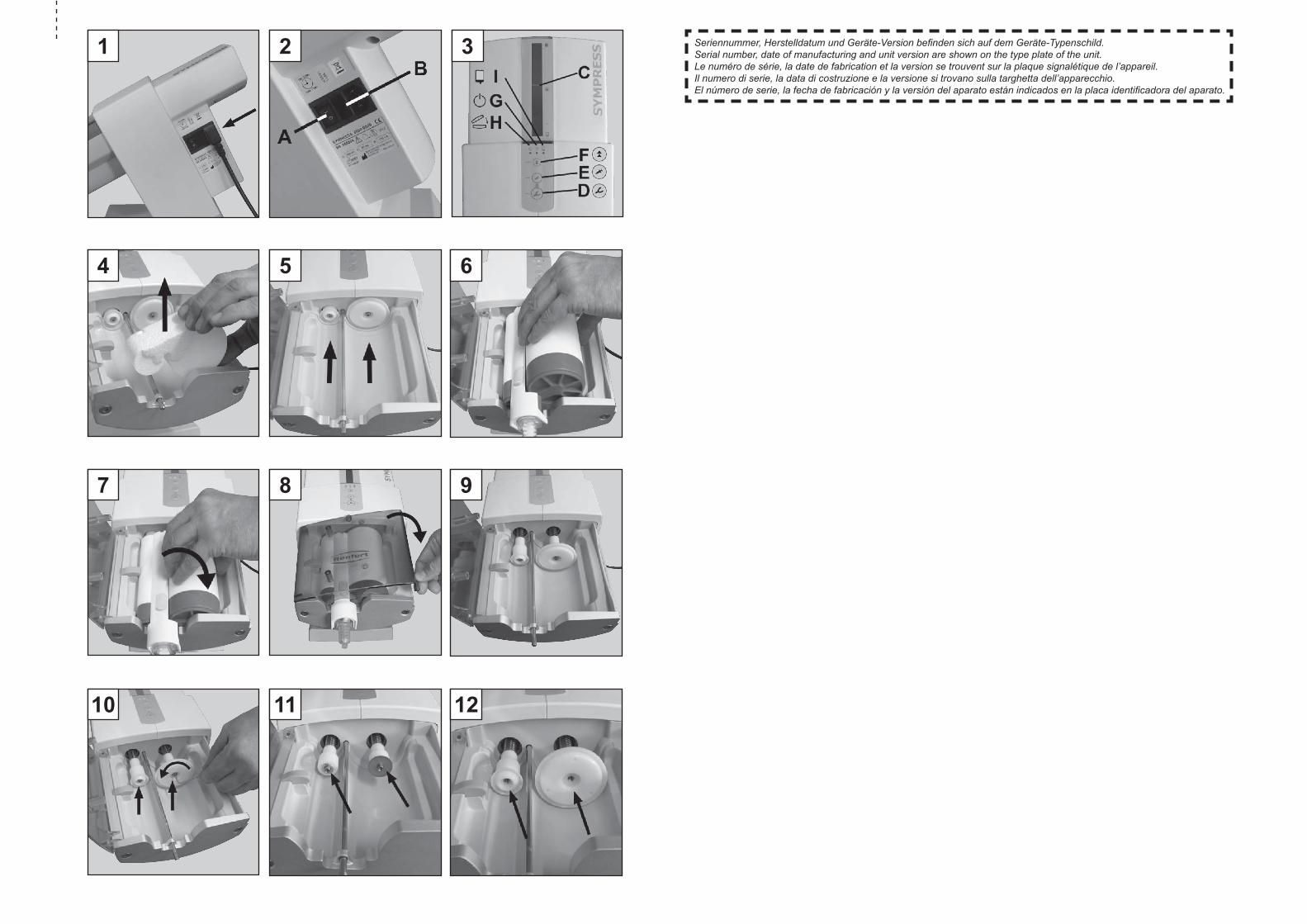
1.5 Shipping RestraintThe shipping restraint must be removed before the unit may be operated:• The unit has been connected and switched on as
described in Section 1.4.• Close the unit cover.• Press the retract key (F, Figure 3):
- The pistons retract to their home position where
they stop.• Open the unit cover.• Remove the shipping restraint (Figure 4).The unit is now ready for use.
2. Operation
2.1 Operating ElementsSee figure 2 and 3.
(A) ON / OFF switch
(B) Device fuse
(C) Fill level indicator
(D) “Impression tray” advance key (fast)
(E) “Dispenser” advance key (slow)
(F) Retract key
(G) Green LED, unit ON
(H) Red LED, unit cover
(I) Yellow LED, remaining amount
Operating Instructions
Only intended for indoor use.
Before opening the unit, disconnect it from the mains power supply by unplugging the power cord from the wall outlet.
1. setup and commissioning
The SYMPRESS can be used as a benchtop unit, although it is also suitable for wall mounting.
1.1 Benchtop UnitSelect a stable underlay on which to set the unit up.
1.2 Wall MountingWith the aid of the wall mounting kit (refer to the ac-cessories), the SYMPRESS can be securely mounted on a wall. The mounting instructions are included in the moun-ting kit.
1.3 Setup RecommendationsOperate the unit at room temperature 18 - 24ºC [64 – 75.2ºF].When setting up the unit, please note the following:• Do not place the unit under a heat source.• Do not place the unit in front of open windows.• Do not set the unit up where it will be subjected to
direct sunlight.• Do not subject the unit to high humidity.
1.4 Connection and Starting Before connecting the unit to the wall out-
let, make sure the voltage information on the nameplate corresponds to your local power supply.
• Connect the provided power cord to the mains con-nection socket (Figure 1).
• Plug the power cord into the wall outlet.• Switch the unit on at the main power switch (A, Fi-
gure 2).
the unit complies with current Eu directi-ves (see section h).
Other symbols are explained as they occur.
- 11 - EN
The threading of the mixer shaft into the mixing nozzle produces an audible noise. This is perfectly normal.
• The pistons advance at high speed until the pressure discs reach the impression material.
• Once the pressure discs contact the impression material, the unit automatically switches to the desired extrusion speed.
4. Fill the impression tray or dispenser. The first 5 cm of material from a newly
installed cartridge or from an again inserted used cartridge should be discarded. Please note the material manufacturer’s recommendations!
5. Release the advance key as soon as the desired amount of material has been extruded.• The pistons retract with a short relief stroke to
prevent any additional impression material from being extruded.
• If the timer is activated, a short audible signal will indicate timer start (refer to Sec. 2.4).
The yellow LED (I) goes on when there is only a small amount of material left in the cartridge (sufficient to fill approx. one more casting spoon) (refer to Sec. 2.5.2).
If the cartridge is emptied during an extru-sion, the pistons automatically return to their home position so that a new cartridge can be quickly installed and the extrusion process can be continued.
2.4 Timer FunctionThe SYMPRESS has an integrated timer.On delivery of the unit the timer is not activated. To activate the timer, see 2.4.1.The activated timer starts automatically at the end of the press cycle. Timer start is indicated by a brief audible signal.
The timer will not start if the advance keys are briefly pressed and released without any impression material being extruded.
The timer employs three different audible signal lengths to indicate the end of three predefined time periods:• After 3 min.: 1 signal• After 4 min.: 2 signals• After 5 min.: 3 signalsThe timer can be stopped by simultaneously pressing both advance keys.
Timer stop is confirmed by a brief audible signal.
2.2 Cartridge Installation and Replacement
A cartridge can only be installed or replaced if both pistons are in their home position (Figure 5).1. Close the unit cover and retract the pistons.
(F, Figure 3)
The pistons return to their home position at high speed and automatically stop.
The pistons will also retract automatically if a cartridge is completely emptied during extrusion.
Simultaneously with the pistons reaching their home position, the mixer shaft is with-drawn from the mixing nozzle so that the cartridge can be removed.
If the piston retract motion is interrupted, either by pressing one of the advance keys or by opening the unit cover, it will not resume automatically. To resume the retract motion you must again press the retract key (F).
2. Install and lock the mixing nozzle in place on the cartridge in accordance with the material manufacturer’s instructions.
3. Open the unit cover.4. Install the cartridge (Figure 6; 7).5. Close the unit cover (Figure 8).
The cover will only close if the cartridge has been properly installed. The red “Unit cover” LED (H) will remain on until the unit cover has been proper-ly closed.
use only mixing nozzles recommended by the material manufacturer. the use of other mixing nozzles may cause the mixing nozz-le to burst.
2.3 Extrusion The pistons will only move if the unit cover
is closed.1. Install a cartridge as described in Sec. 2.2.2. Press and hold down the advance key
(depending on the desired speed or function):• Impression tray
or
• Dispenser
The key with the casting spoon symbol can
be used to fill the impression tray more quickly. The key with the syringe symbol is more suitable for a slower filling, e.g., of a syringe.
3. The mixer shaft is activated in order to allow the hexagonal end to thread itself into the mixing noz-zle.

- 12 -EN
3.2 Disinfection Never use superheated steam for disinfec-
tion!The following products can be used for disinfection:• Incidur Spray (Ecolab)• Incides N wipes (Ecolab)Ensure adequate ventilation following disinfection to prevent an explosion-prone area.
3.3 Pressure Disc ReplacementThe pressure discs are subject to wear as a result of their rubbing against the inner cartridge wall.Highly abraded pressure plates can damage the foil bag.To replace the pressure plate:1. Move the pistons to their home position and remo-
ve the cartridge.2. Close the unit cover and advance the pistons
approx. 1/3 of their travel path (Figure 9).3. Open the unit cover and unplug the power cord
from the wall outlet.4. Loosen the fastening screw on the desired pressu-
re disc (Figure 10) and remove the pressure disc and support disc.
5. Slide support disc onto the spindle (Figure 11).6. Install a new pressure plate (Figure 12).7. Secure with a new fastening screw (including was-
her) (Figure 13).8. Close the unit cover and return the pistons to their
home position. The pressure disc screws have been coa-
ted with a special adhesive to prevent them from loosening themselves. Always use new screws when replacing a pressure disc.
3.4 Unit Cover Replacement1. Move the pistons to their home position and remo-
ve the cartridge.2. Close the unit cover and advance the pistons
approx. 1/3 of their travel path (Figure 9).3. Loosen and unscrew the pressure plate screws
approx. 5 mm (Figure 14). cAutION, Risk of Injury!
the screws have been securely tightened. there is a risk of injury by the tool when loosening the screws. Grasp the tool firmly and hold it securely.
4. Pull the pressure plate forward (Figure 15) until the unit cover can be taken out of the hinge (Figu-re 16).
5 Install a new unit cover.6. Push the pressure plate back to its home position
and retighten the screws. take care not to jam the unit cover!
7. Close the unit cover and return the pistons to their home position.
2.4.1 Timer funcTion on/offThe overall timer function can be activated or deacti-vated:To do this:• Switch the unit off.• Press and hold both advance keys.• While continuing to hold the advance keys, switch
the unit on again:• Brief audible signal: Timer function is
deactivatedor• Long audible signal: Timer function is activated
• Release both advance keys.
2.5 Fill Level Indicator and Remaining Amount
2.5.1 fill level indicATor
The fill level indicator (C, Figure 3) helps you to esti-mate the amount of impression material remaining in the cartridge. However, after installing a new cart-ridge or if the cartridge is very full, the indicator will at first not be visible. The indicator will only become visible once the pis-tons have advanced approx. 25 mm into the cart-ridge.
2.5.2 remAining AmounT deTecTion
The SYMPRESS is equipped with an electronic fill level detection. Once there is only sufficient material remaining in a cartridge to fill approx. one casting spoon, the yellow “Residual level” LED (I, Figure 3) goes on.
3. cleaning / MaintenanceTo clean the unit, merely wipe it down with a moist cloth.
Never use cleansers containing solvents.
3.1 Cleaning the InteriorWith the pistons retracted, the cartridge bed is easily accessible for cleaning.Without a cartridge installed, the pistons can be retracted to the appropriate position to permit the removal of residue from the pressure discs or the spindle covers.
NEVER clean the spindles themselves. the grease applied to spindles is necessary for the unit’s proper function.
tip:Remnants of impression material are most easily removed with a dry cloth or paper towel.
- 13 - EN
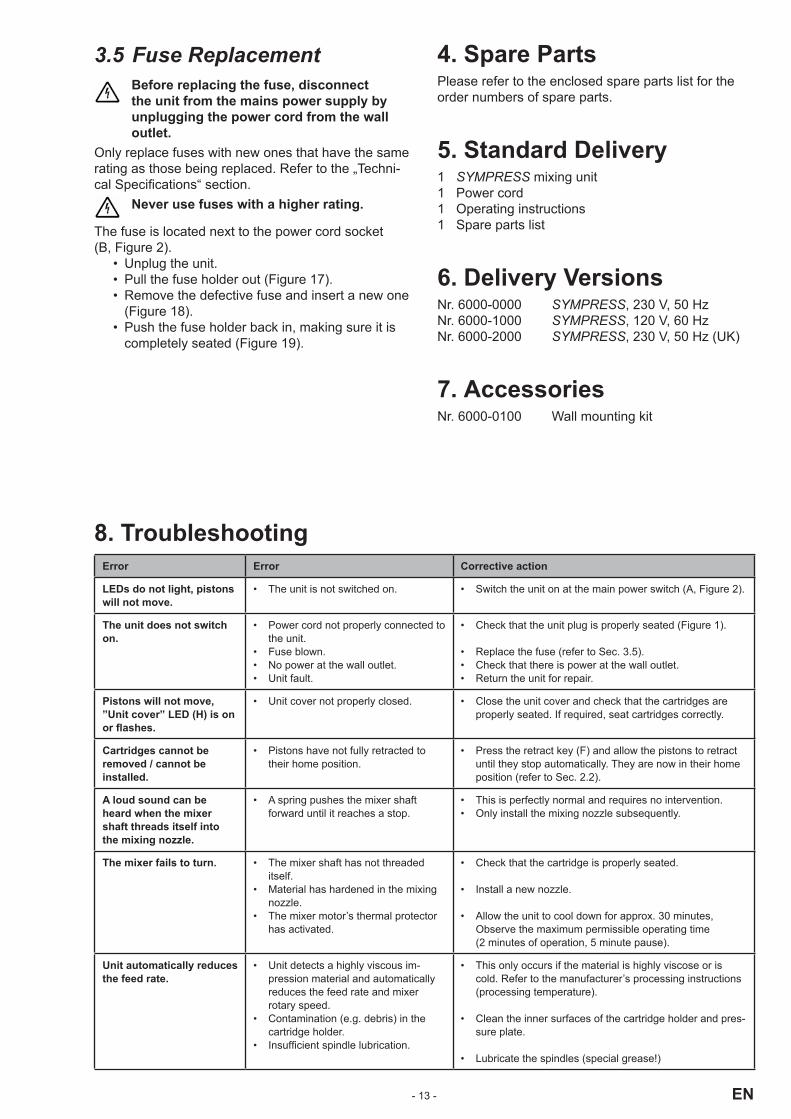
8. troubleshootingError Error corrective action
LEDs do not light, pistons will not move.
• The unit is not switched on. • Switch the unit on at the main power switch (A, Figure 2).
the unit does not switch on.
• Power cord not properly connected to the unit.
• Fuse blown.• No power at the wall outlet.• Unit fault.
• Check that the unit plug is properly seated (Figure 1).
• Replace the fuse (refer to Sec. 3.5).• Check that there is power at the wall outlet.• Return the unit for repair.
Pistons will not move, ”unit cover” LED (h) is on or flashes.
• Unit cover not properly closed. • Close the unit cover and check that the cartridges are properly seated. If required, seat cartridges correctly.
cartridges cannot be removed / cannot be installed.
• Pistons have not fully retracted to their home position.
• Press the retract key (F) and allow the pistons to retract until they stop automatically. They are now in their home position (refer to Sec. 2.2).
A loud sound can be heard when the mixer shaft threads itself into the mixing nozzle.
• A spring pushes the mixer shaft forward until it reaches a stop.
• This is perfectly normal and requires no intervention.• Only install the mixing nozzle subsequently.
the mixer fails to turn. • The mixer shaft has not threaded itself.
• Material has hardened in the mixing nozzle.
• The mixer motor’s thermal protector has activated.
• Check that the cartridge is properly seated.
• Install a new nozzle.
• Allow the unit to cool down for approx. 30 minutes, Observe the maximum permissible operating time (2 minutes of operation, 5 minute pause).
unit automatically reduces the feed rate.
• Unit detects a highly viscous im-pression material and automatically reduces the feed rate and mixer rotary speed.
• Contamination (e.g. debris) in the cartridge holder.
• Insufficient spindle lubrication.
• This only occurs if the material is highly viscose or is cold. Refer to the manufacturer’s processing instructions (processing temperature).
• Clean the inner surfaces of the cartridge holder and pres-sure plate.
• Lubricate the spindles (special grease!)
3.5 Fuse Replacement Before replacing the fuse, disconnect
the unit from the mains power supply by unplugging the power cord from the wall outlet.
Only replace fuses with new ones that have the same rating as those being replaced. Refer to the „Techni-cal Specifications“ section.
Never use fuses with a higher rating.
The fuse is located next to the power cord socket (B, Figure 2).
• Unplug the unit.• Pull the fuse holder out (Figure 17).• Remove the defective fuse and insert a new one
(Figure 18).• Push the fuse holder back in, making sure it is
completely seated (Figure 19).
4. spare PartsPlease refer to the enclosed spare parts list for the order numbers of spare parts.
5. standard Delivery1 SYMPRESS mixing unit1 Power cord1 Operating instructions1 Spare parts list
6. Delivery VersionsNr. 6000-0000 SYMPRESS, 230 V, 50 HzNr. 6000-1000 SYMPRESS, 120 V, 60 HzNr. 6000-2000 SYMPRESS, 230 V, 50 Hz (UK)
7. AccessoriesNr. 6000-0100 Wall mounting kit

- 14 -EN
The following information is intended to assist you, the operator, in safely working with the SYMPRESS in your laboratory.
using these operating instructions as a starting point, instruct all operators of the unit with regard to the area of application, the possible hazards during operation, and the proper operation of the unit.
Please have these operating instructions readily available for the operators.
A. Application Area
A.1 Proper UseThe SYMPRESS is designed solely for the extrusion of 2-component precision impression materials. The SYMPRESS is capable of working with 5:1 cart-ridges or tubular bags in reinforcing cartridges from various manufacturers.
Always comply with all safety and processing instructions provided by the manufacturer!
Impression materials are to be processed in accordance with the manufacturer’s instructions!
Dynamic mixing nozzles with hexagonal head drives can be used for mixing.
Only the mixing nozzles specified by the manufacturer may be employed.
A.2 Ambient conditions for safe operation
Safe operation of the unit can only be ensured under the following ambient conditions:• Indoors;• Up to an altitude of 2,000 m above sea level;• At an ambient temperature range between
15 - 40ºC [59 - 104ºF] *);• At a maximum relative humidity of 80% at 31ºC
[87.8ºF], dropping in a linear manner to 50% relative humidity at 40ºC [104ºF] *);
• With mains power where the voltage fluctuations do not exceed 10% of the nominal value;
• Under contamination level 2 conditions;• Under over-voltage category II conditions.*) Between 15 – 30°C [59 – 86°F], the unit can be operated at
a relative humidity of up to 80%. At temperatures between 31 – 40°C [87.8 – 104°F], the humidity must decrease proportionally in order to ensure operational readiness (e.g., at 35°C [95°F] = 65% humidity; at 40°C [104°F] = 50% humidity). The unit may not be operated at temperatures above 40°C [104°F].
A3. Ambient conditions for storage and transport
Ensure the following ambient conditions during sto-rage and transport:• Ambient temperature -20 – +60ºC [-4 – +140ºF],• Maximum relative humidity 80%
Information for Operators
Error Error corrective action
the mixing nozzle bursts. • Incorrect mixing nozzle installed.• Mixing tip/ foil bag not compatible.
• Use the mixing nozzle specified by the manufacturer.• Contact the manufacturer of the mixing tip / foil bag.
the tubular bag bursts or is damaged.
• Pressure discs are too worn or have been damaged, causing the tubular bag to be pinched between the pres-sure disc and the cartridge.
• The material has partially hardened in the cartridge.
• Replace the pressure discs (refer to Sec. 3.3).
• Replace the cartridge (refer to Sec. 2.2).
Advance stops for no apparent reason and the unit performs a short relief stroke.
• The controller has detected an over-load.
• Material has hardened in the cart-ridge.
• Insufficient spindle lubrication.
• Impression material is too cold, Refer to the manufacturer’s processing instructions.
• Use a new cartridge.
• Lubricate the spindles (special grease!)

- 15 - EN
B. hazard and Warning Information Only intended for indoor use. the unit is
only designed for dry applications and may not be operated or stored outdoors or un-der wet conditions.
the unit may only be operated with a power cord equipped with a plug appropriate to the local power supply.
Before commissioning, compare the in-formation on the nameplate with den the specifications of your local mains power supply.
Regularly inspect connecting lines and ho-ses (e.g., the power cord) for damage (e.g., kinks, cracks, porosity) or signs of aging. units exhibiting damaged connecting lines, hoses, or other defects must be taken out of service immediately.
Always unplug the unit from the wall outlet before beginning any work on the unit’s electrical components.
Do not allow the unit to be operated without supervision.
Note any hazard or warning information provided by the material manufacturer.
Do not operate in an explosion-prone area.
c. Authorised IndividualsThis product may not be used by minors under the age of 14. Only properly trained individuals may operate and service the unit.Any repairs not specifically described in these opera-ting instructions may only be performed by a qualified electrician.
D. Preparations Prior to starting Before operating the unit, make sure the
voltage information on the nameplate corresponds to your local power supply.
E. Maintenance / RepairRepairs may only be performed by qualified electrici-ans or authorized dealers.
F. Disposal Information
F.1 Disposing of ConsumablesEmpty cartridges and tubular bags as well as used mixing nozzles must be disposed of in accordance with the manufacturer’s instructions.
F.2 Instrument DisposalThe instrument must be disposed of by a specialist facility. This specialist facility must be informed of any hazardous residue in the instrument.
f.2.1 diSpoSAl informATion for eu nATionS
In order to maintain and protect the environment, to prevent environmental contamination and to improve the reutilisation of raw materials (recycling), the Euro-pean Commission has established guidelines accor-ding to which manufacturers must take back electrical and electronic devices in order to forward them to a regulated disposal or recycling system.Within the European Union, devices identified with this symbol may therefore not be disposed of with unsorted municipal solid waste:
For more information regarding proper disposal and options for returning used instruments, please go to:www.renfert.com
f.2.2 informATion of pArTiculAr relevAnce To germAn cuSTomerS
Renfert electrical instruments are devices intended for commercial use.These instruments may not be disposed of at mu-nicipal collection points for electrical and electronic equipment, but instead, are accepted directly by Renfert.For more information regarding current return opti-ons, please go to our Internet pages at:www.renfert.com
G. Technical SpecificationsMains voltage: 230 V, 50 Hz 120 V, 60 HzPower consumption: 170 WMains input fuse: 2 x 1.6 A (T) (230 V) 2 x 3.15 A (T) (120 V)Dimensions (height x width x length): 330 x 190 x 380 mm (13 x 7.5 x 15 inches)Weight (empty): 7.0 kgNoise level: < 70 dB(A)

- 16 -ENWe reserve the right to make technical changes.
h. Eu conformityRenfert GmbH hereby declares that this product:
SYMPRESSOrder no.: 6000-0000, -1000, -2000complies with the following European directives:93/42/EWG, Medical Products Directive
I. Liability ExclusionRenfert GmbH shall be absolved from all claims for damages or warranty if:• The product is employed for any purposes
other than those cited in the operating instructions;
• The product is altered in any way other than those alterations described in the operating instructions;
• The product is repaired by other than an authorised facility or if any but Renfert OEM parts are employed;
• The product continues to be employed, despite obvious safety faults or damage;
• The product is subjected to mechanical impacts or is dropped.
We do not accept any liability for damage caused by mixing tips, foil bags or cartridges splitting.
K. WarrantyProvided the unit is properly used, Renfert warrants the all components of the SYMPRESS mixing unit for a period of 3 years. Warranty claims may only be made upon presentation of the original sales receipt from the authorized dealer. Components subject to natural wear as well as consumable (e.g., fuses, pressure plates, etc. ...) are excluded from this war-ranty.The warranty is voided in case of improper use; failu-re to observe the operating, cleaning, maintenance, and connection instructions; in case of independent repairs or repairs by unauthorized personnel; if spare parts from other manufacturers are employed, or; in case of unusual influences or influences not in com-pliance with the utilization instructions.Warranty service shall not extend the original warran-ty.